Tensairity Concept Applied to Lighter-Than-Air Vehicles ...
9
1 Copyright © 2014 by ASME TENSAIRITY CONCEPT APPLIED TO LIGHTER-THAN-AIR VEHICLES FOR LIGHT- WEIGHT STRUCTURES Anna Suñol Vrije Universiteit Brussel, Department of Mechanical Engineering Brussels, Belgium Dean Vucinic Vrije Universiteit Brussel, Department of Mechanical Engineering Brussels, Belgium Lars De Laet Vrije Universiteit Brussel, Department of Architectural Engineering Brussels, Belgium ABSTRACT Airships have the intrinsic advantages of Lighter-Than-Air (LTA) vehicles: minimal energy consumption and Vertical Take-Off and Landing (VTOL) characteristics. Due to these advantages, significant efforts are being taken in order to investigate new applications and technical improvements. More specifically, there is a renewed interest in large airships for heavy payload transportation and for stratospheric airships. The design of large airships is a big challenge, especially when considering the structural point of view, since big volumes imply high loads, and since light weight is a major requirement for this type of vehicles. In this context, a light-weight structure is proposed by applying the structural Tensairity concept. A Tensairity beam consists of a rigid air beam designed on the basis of complete functional separation of the different structural elements, allowing for a maximum optimization. In this paper, the justification of the feasibility of applying Tensairity components in airships is discussed based on two criteria. The first criterion is the justification of the need of a lightweight structure by a state of the art analysis and a study of the principal characteristics of the existing types of LTA vehicles structures. The second criterion is a preliminary technical analysis, which aims to clarify if the load bearing behavior of airships is suited for the application of the Tensairity concept. Moreover, the bases for the development of the concept for the LTA vehicles structures are established. The advantages and drawbacks of the traditional rigid airships structure in comparison with a non-rigid structure has been analyzed, which conclusion is that the use of a rigid structure is convenient for large airships, since it reduces significantly the stresses of the envelope, but at the same time decreases the payload efficiency due to the addition of the structure's weight. Moreover, the analysis of the load bearing behavior suggests the technical feasibility of applying Tensairity components, since airships have to withstand high bending moments and Tensairity structures are appropriate for withstanding such loads. Finally, the principal guidelines for defining the various load cases and for modeling Tensairity beams have been defined. In order to confirm the hypothesis of the suitability of Tensairity structures on airships, extensive research on design, analysis and optimization of Tensairity beam grids in typical airship loading conditions is needed. INTRODUCTION It is well known that Lighter-than-air (LTA) vehicles, like the "zeppelin" airships, were a common transport system in the beginning of last century. Nowadays, LTA vehicles are being again intensively researched, by focusing on the use of new materials, techniques and applications for constructing a future generation of airships [1]. The reason of this renewed interest is related to the main advantage of applying the LTAs concept: LTAs vehicles fly by the presence of the buoyancy forces, which implies that the propulsive forces are very small when compared to the standard aircrafts propulsion requirements. In other words, the buoyancy forces eliminate the necessity of producing energy to generate the required lift force in order to counteract the airship weight. Another advantage intrinsic to LTA is its hovering capabilities, which enables vertical take-off and landing (VTOL). One of the main requirements in the structural LTA’s design is the minimization of weight to increase the transported payload. In this line, a new light-weight structural concept is proposed, which applies Tensairity components. Tensairity is a recent concept of a lightweight structure based on the complete functional separation of tension and compression elements, enabling a separated weight-optimization for each structural element [2]. It consists of air-beams, in combination with rigid elements for supporting compression and cables to counteract to the traction stresses. Tensairity beams are expected to reduce the structural weight significantly for identical span and maximum load requirement, when compared to the conventional girders. As an example, a Tensairity beam of 10m Proceedings of the ASME 2014 International Mechanical Engineering Congress and Exposition IMECE2014 November 14-20, 2014, Montreal, Quebec, Canada IMECE2014-38174
Transcript of Tensairity Concept Applied to Lighter-Than-Air Vehicles ...
1 Copyright © 2014 by ASME
TENSAIRITY CONCEPT APPLIED TO LIGHTER-THAN-AIR VEHICLES FOR LIGHT-WEIGHT STRUCTURES
Anna Suñol Vrije Universiteit Brussel,
Department of Mechanical Engineering
Brussels, Belgium
Dean Vucinic Vrije Universiteit Brussel,
Department of Mechanical Engineering
Brussels, Belgium
Lars De Laet Vrije Universiteit Brussel,
Department of Architectural Engineering
Brussels, Belgium
ABSTRACT Airships have the intrinsic advantages of Lighter-Than-Air
(LTA) vehicles: minimal energy consumption and Vertical
Take-Off and Landing (VTOL) characteristics. Due to these
advantages, significant efforts are being taken in order to
investigate new applications and technical improvements. More
specifically, there is a renewed interest in large airships for
heavy payload transportation and for stratospheric airships. The
design of large airships is a big challenge, especially when
considering the structural point of view, since big volumes
imply high loads, and since light weight is a major requirement
for this type of vehicles. In this context, a light-weight structure
is proposed by applying the structural Tensairity concept. A
Tensairity beam consists of a rigid air beam designed on the
basis of complete functional separation of the different
structural elements, allowing for a maximum optimization. In
this paper, the justification of the feasibility of applying
Tensairity components in airships is discussed based on two
criteria. The first criterion is the justification of the need of a
lightweight structure by a state of the art analysis and a study of
the principal characteristics of the existing types of LTA
vehicles structures. The second criterion is a preliminary
technical analysis, which aims to clarify if the load bearing
behavior of airships is suited for the application of the
Tensairity concept. Moreover, the bases for the development of
the concept for the LTA vehicles structures are established.
The advantages and drawbacks of the traditional rigid airships
structure in comparison with a non-rigid structure has been
analyzed, which conclusion is that the use of a rigid structure is
convenient for large airships, since it reduces significantly the
stresses of the envelope, but at the same time decreases the
payload efficiency due to the addition of the structure's weight.
Moreover, the analysis of the load bearing behavior suggests
the technical feasibility of applying Tensairity components,
since airships have to withstand high bending moments and
Tensairity structures are appropriate for withstanding such
loads. Finally, the principal guidelines for defining the various
load cases and for modeling Tensairity beams have been
defined. In order to confirm the hypothesis of the suitability of
Tensairity structures on airships, extensive research on design,
analysis and optimization of Tensairity beam grids in typical
airship loading conditions is needed.
INTRODUCTION It is well known that Lighter-than-air (LTA) vehicles,
like the "zeppelin" airships, were a common transport system in
the beginning of last century. Nowadays, LTA vehicles are
being again intensively researched, by focusing on the use of
new materials, techniques and applications for constructing a
future generation of airships [1]. The reason of this renewed
interest is related to the main advantage of applying the LTAs
concept: LTAs vehicles fly by the presence of the buoyancy
forces, which implies that the propulsive forces are very small
when compared to the standard aircrafts propulsion
requirements. In other words, the buoyancy forces eliminate the
necessity of producing energy to generate the required lift force
in order to counteract the airship weight. Another advantage
intrinsic to LTA is its hovering capabilities, which enables
vertical take-off and landing (VTOL).
One of the main requirements in the structural LTA’s design is
the minimization of weight to increase the transported payload.
In this line, a new light-weight structural concept is proposed,
which applies Tensairity components. Tensairity is a recent
concept of a lightweight structure based on the complete
functional separation of tension and compression elements,
enabling a separated weight-optimization for each structural
element [2]. It consists of air-beams, in combination with rigid
elements for supporting compression and cables to counteract
to the traction stresses. Tensairity beams are expected to reduce
the structural weight significantly for identical span and
maximum load requirement, when compared to the
conventional girders. As an example, a Tensairity beam of 10m
Proceedings of the ASME 2014 International Mechanical Engineering Congress and Exposition IMECE2014
November 14-20, 2014, Montreal, Quebec, Canada
IMECE2014-38174

2 Copyright © 2014 by ASME
span, slenderness γ of 10 and a distributed load of 2kN/m is by
factor of 6 lighter than a steel HEB profile beam, when
designed for similar conditions [3]. The larger the slenderness,
the larger this factor will be. Such reduction in weight, in
combination with the property of an increasing performance
with length, suggests the possibility of applying Tensairity as
primary structural components for airships, expecting to yield
similar results. Such a property makes Tensairity an interesting
alternative for building LTA structures and an attempt following
such approach has been developed and researched in this paper.
The motivation underpinning such idea of applying Tensairity
in LTA vehicles was born within the framework of the
Multibody Advanced Airship for Transport (MAAT) project,
which design involves the structural analysis of a non-
conventional large stratospheric airship [4]. Concerning the
structural design, its main challenges are its large dimensions
and its non-conventional shape. Concerning the dimensions, the
airship is 346m of length, 218m span and 66m height, as shown
in Figure 1. It is conceived as the biggest airship ever designed.
Regarding the shape, the optimal geometries for pressurization
are the sphere or the cylinder, while MAAT geometry is
ellipsoidal and with a central hole due its mission requirements.
Until today, the study of the MAAT design have comprised
different disciplines, such as the preliminary airships
specifications [5], aerodynamic studies [6], power estimations
[7] or the docking procedure [8], among others, and along the
structural analysis the application of Tensairity beams has been
proposed. Consequently, the application of Tensairity beams for
airships has been decided to be further investigated.
Figure 1: MAAT project
The first step to apply Tensairity beams in the MAAT airships is
to investigate the feasibility of Tensairity beams in airships.
Thus, a literature study of the Tensairity structural principle and
its application in the relation to the airship characteristics has
been carried out. Along this line, the section LTA
STRUCTURES explores the existing types of airships
structures and compares their advantages and drawbacks.
Secondly, the section TENSAIRITY defines the principle and
main characteristics of Tensairity beams and presents already
existing applications. In addition, a justification of the use of
light-weight structures from a state-of-the-art perspective is
presented in the section TENSAIRITY APPLIED TO LTA
VEHICLES ADVANTAGES. From a technical perspective, the
application justification can be found in the section
MODELING LTA LOADING CONDITIONS, as well as the
definition of the modeling process to characterize such loads, as
input into the FEA solver. Moreover, in the section SECURITY
FACTORS AND STRUCTURAL DESIGN CRITERIA, the
most important criteria for a structural design in airships is
presented. Finally, in the section MODELING TENSAIRITY
BEAMS, the relevant aspects of the Tensairity beams process is
defined.
In general, the aim of this paper is to investigate the possible
benefits and the feasibility of Tensairity structures in LTA
vehicles and provide the methodological basis needed for the
development of the Tensairity concept application.
LTA STRUCTURES LTA are classified in 3 groups according to their
structure: (a) non-rigid airships, (b) semi-rigid airships and (c)
rigid airships. Figure 2 shows the main structural characteristics
of the three types of airships.
Non-rigid airships, or blimps, are those LTAs, which shape is
maintained solely by the envelope overpressure: the differential
pressure between the inner lifting gas and the outer atmosphere
pushes the envelope to the desired shape, counteracting all
other involved forces. In other words, the envelope is the main
primary structure carrying all the loads: gondola loads,
aerodynamic forces… Simple structures exist in the critical
areas (as the nose cone) where otherwise the fabric would need
to be thicker, in order to withstand the loads only by itself.
Loads are transmitted to the envelope by a system of cables and
distributed by a suspension system (adjustable catenary cable
system). Due to the absence of a rigid structure, non-rigid
airships are light, easy to design, build and maintain. However,
as the volume of the airship increases, drawbacks related to
manufacturing and maximum load bearing of the membrane
appear. Consequently, non-rigid airships are suitable for small
airships [1].
Semi-rigid structures consists both of a rigid keel and a
catenary suspension system that still carries load, although
playing a much reduced load in comparison to the non-rigid
structures. The rigid keel distributes the gondola weight along
the entire length of the airship and eliminates the main function
of the catenary curtain, although the envelope still acts as a
primary structure, due to the poor fit of keel and envelope.
Thus, the envelope still carries aerodynamic bending loads.
Consequently, the envelope is still partially responsible of
maintaining the desired shape by its overpressure [1].
Rigid airships are supported by a framework, which carries all
the loads and by itself maintains the shape of the airship, while
the purpose of the envelope is solely to maintain the presence
of the lifting gas inside. Consequently, the strength requirement
is much lower, allowing the use of lighter fabrics. Rigid
airships allow gas compartmentalization, which increases
safety. Rigid airships are not appropriate for sizes below one
million cubic feet (around 28,300 m3) volume. Its major benefit

3 Copyright © 2014 by ASME
is that there is no size restriction due to the envelope fabric
strength, which allows for larger volumes dimensions [9].
Figure 2: Graphical description of non-rigid, semi-rigid and rigid airships (Source, ref. [1])
According to such definitions, the design decision of non-rigid,
semi-rigid and rigid structures depends on the volume of the
airship, being the non-rigid the most suitable for small airships.
In addition, in the case of non-conventional shape airships,
where maintaining the shape only supported by the envelope is
challenging, the use of rigid structures might also be beneficial.
TENSAIRITY Tensairity is a recent light weight structural concept
based on tensegrity or, in other words, by the complete
functional separation of its structural elements. A basic
Tensairity beam consists of a beam made of 3 elements [10]:
cables, which solely withstand traction; a strut, which solely
withstands compression; and a pressurized membrane, which
pretensions the cables and stabilizes the compression element
against buckling. Its innovation, when compared to tensegrity,
is the addition of the pressurized membrane, which provides
cohesion and rigidity to the structure by pre-tensioning its
cables. Figure 3 shows the concept of Tensairity. Cables and
strut are connected, thus transmitting the forces to each other.
They are the only elements carrying load, and the membrane
acts only for stabilization. Tensairity beams are conceived as
effective beams for withstanding bending moments.
Figure 3: A Tensairity beam consists of a tension element (cable), a compression element (strut) and stabilizing element (membrane), each of them solely carrying one type of stress. (Source, ref. [2]).
If compared to a regular beam or a truss girder, the central rigid
elements are eliminated and substituted by an air beam. Such
central rigid elements of the conventional structures are not
optimal; since stresses are concentrated in the upper and lower
areas, and since central elements must be dimensioned for
buckling instead of for yield stress. By the elimination of such
elements and substitution by an air beam, there is automatically
a significant decrease of weight, while conserving high beam
inertia.
In addition to the suppression of central elements, the
membrane increases the buckling load by acting as a
continuous elastic support [3]. In the case of a simply supported
conventional beam which withstands compression, the buckling
force is defined as described in (1). In order to increase the
buckling force, it is common to apply vertical supports, which
effect is analogue to the reduction of the beam length. Equation
(2) shows the buckling force for the simply supported beams
having n vertical supports. Tensairity beams use a membrane as
a continuous elastic support, increasing the buckling force of
the compression element as shown in equation (3), where k is
defined as shown in (4).
𝑃𝑏 = 𝜋2 ·𝐸 · 𝐼
𝐿𝑏2
(1)
𝑃𝑏 = (𝑛 + 1)2 · 𝜋2 ·𝐸 · 𝐼
𝐿𝑏2
(2)
𝑃𝑏 = 𝑘 · 𝜋2 ·𝐸 · 𝐼
𝐿𝑏2
(3)
𝑘 = 𝜋𝑝
(4)
As a consequence, by selecting a proper inertia and internal air
beam pressure, the compression element can be dimensioned to

4 Copyright © 2014 by ASME
withstand the yield stress, instead of buckling criteria. Thus, all
the elements are dimensioned for the yield stress, leading to a
weight reduction - optimal structure. Tensairity beams can be
order of magnitude lighter than the girder beams, when
considered for the same span and load conditions [10].
Moreover, as the membrane does not carry loads, but acts as a
stabilization element, its internal pressure and membrane force
are independent of the length and slenderness of the beam.
Thus, large spans can be covered with the application of such
light beams. Considering the mentioned characteristics, Tensairity has an added value, due to its significant reduction on weight, its large span, easy storage, transportation and erection (95% of its volume is air) [3],
having a high potential for being used for wide span roof structures, temporary bridges and temporary buildings. Extensive research is being conducted, aiming to improve the design of the
Tensairity structures for different loads and constraints, as well as for different applications. Indeed, some Tensairity structures have
been already designed and successfully implemented as roof, bridge, or portable hangars. Tensairity horizontal beams are being
continuously researched and optimized [2].
Figure 4 shows already existing Tensairity beams applications,
all of them in the architectural domain.
Figure 4: Tensairity has already been successfully applied as long span beams for a roof and bridge, and for portable hangars.
There is a precedent of a Tensairity in an aeronautic
application, in current development, based on the construction
of inflatable kites. The aim of applying Tensairity on inflatable
wings is to increase the small load-bearing capacity of such
structures, which limits the aspect ratio of this wing type. For
such application, the Tensairity beams were needed to be
curved in order to be able to build wings with dihedral, sweep
and twist. A prototype was made and successfully flied,
demonstrating a higher performance than conventional air
beams in terms of weight, crash resistance, buckling load and
rigidity [11].
TENSAIRITY APPLIED TO LTA VEHICLES ADVANTAGES
In the section LTA structures, from a structural point of
view, three types of airships have been presented and their main
characteristics defined. An important conclusion of such
classification is the drawbacks of the non-rigid airships
structures requiring large volumes, which is principally due to
the high stresses on the envelope. These high stresses come
from the internal over-pressure, which maintains the envelope
shape under the load conditions. The Hoop stress equation (5)
relates a linear dependence of the envelope stress in respect to
the cylinder radius. Although equation (5) does not apply to an
airship, which geometry is not perfectly cylindrical, it provides
a qualitative sense of the effect of the envelope radius on the
envelope stresses.
𝜎ℎ =𝑃 · 𝑟
𝑡
(5)
Indeed, after the state-of-the-art study, it became clear that the
biggest airships ever built were rigid. Figure 5 shows the length
of several airships that have been in use, without considering
the projects currently under development. The conclusion is
that the biggest airships that have ever flown were rigid. It is
relevant to mention that all rigid airships were from the
previous century and not active for more than 90 years. Figure
5, thus compares vehicles designed using new and old
technologies. Nowadays, the use of composite materials and
structural software is enabling the design of higher performance
rigid airships. The data in Figure 5 has been extracted from
[12], [13], [14], [15], [16] and [9].
In addition, Figure 6 shows several current airship projects,
evidencing a nowadays renewed interest for large airships,
principally focusing on heavy payloads and stratospheric high-
altitude airships. The reasons of this new interest are the
advances in the design of higher performance materials,
propulsion, solar panels, and energy storage systems, as well as
the need for a more eco-oriented approach [17]. The data
shown in Figure 6 is obtained from [18], [14], [16] and [4].
5 Copyright © 2014 by ASME
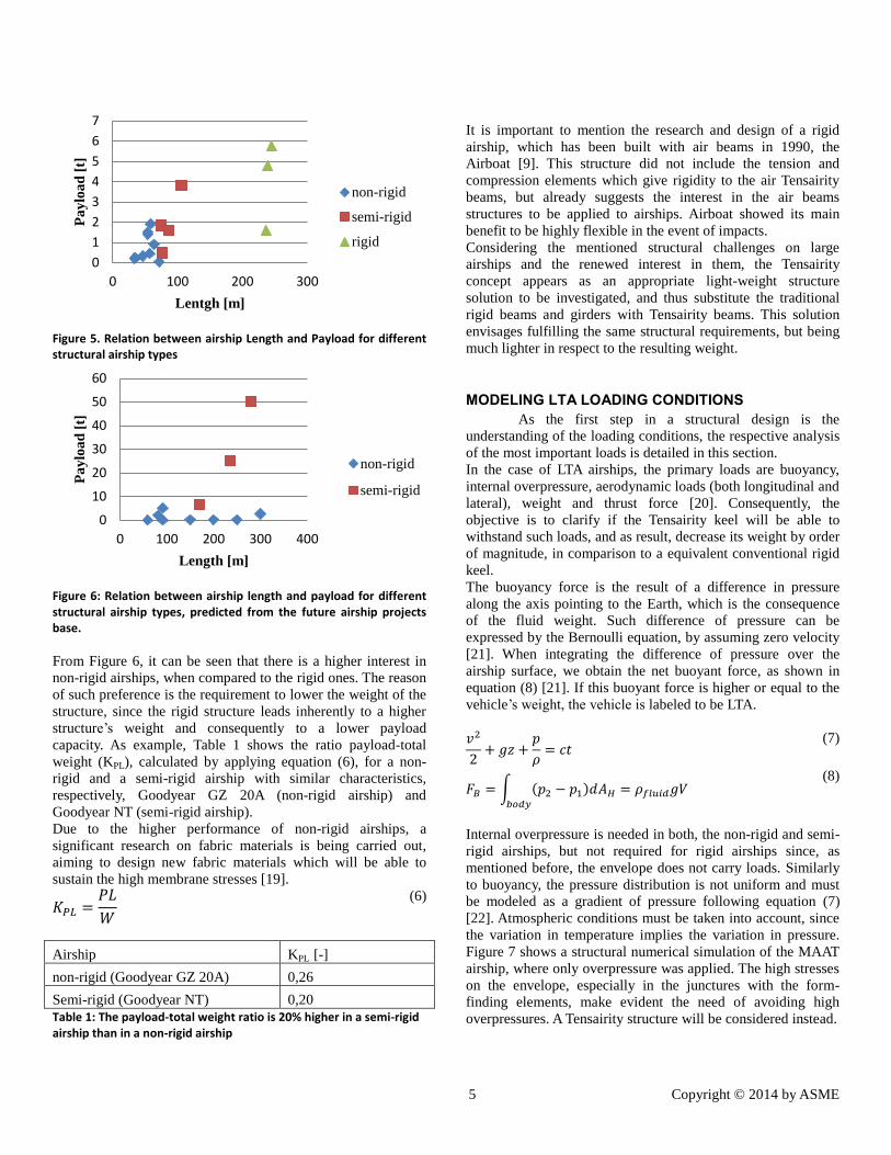
Figure 5. Relation between airship Length and Payload for different structural airship types
Figure 6: Relation between airship length and payload for different structural airship types, predicted from the future airship projects base.
From Figure 6, it can be seen that there is a higher interest in
non-rigid airships, when compared to the rigid ones. The reason
of such preference is the requirement to lower the weight of the
structure, since the rigid structure leads inherently to a higher
structure’s weight and consequently to a lower payload
capacity. As example, Table 1 shows the ratio payload-total
weight (KPL), calculated by applying equation (6), for a non-
rigid and a semi-rigid airship with similar characteristics,
respectively, Goodyear GZ 20A (non-rigid airship) and
Goodyear NT (semi-rigid airship).
Due to the higher performance of non-rigid airships, a
significant research on fabric materials is being carried out,
aiming to design new fabric materials which will be able to
sustain the high membrane stresses [19].
𝐾𝑃𝐿 =𝑃𝐿
𝑊
(6)
Airship KPL [-]
non-rigid (Goodyear GZ 20A) 0,26
Semi-rigid (Goodyear NT) 0,20
Table 1: The payload-total weight ratio is 20% higher in a semi-rigid airship than in a non-rigid airship
It is important to mention the research and design of a rigid
airship, which has been built with air beams in 1990, the
Airboat [9]. This structure did not include the tension and
compression elements which give rigidity to the air Tensairity
beams, but already suggests the interest in the air beams
structures to be applied to airships. Airboat showed its main
benefit to be highly flexible in the event of impacts.
Considering the mentioned structural challenges on large
airships and the renewed interest in them, the Tensairity
concept appears as an appropriate light-weight structure
solution to be investigated, and thus substitute the traditional
rigid beams and girders with Tensairity beams. This solution
envisages fulfilling the same structural requirements, but being
much lighter in respect to the resulting weight.
MODELING LTA LOADING CONDITIONS As the first step in a structural design is the
understanding of the loading conditions, the respective analysis
of the most important loads is detailed in this section.
In the case of LTA airships, the primary loads are buoyancy,
internal overpressure, aerodynamic loads (both longitudinal and
lateral), weight and thrust force [20]. Consequently, the
objective is to clarify if the Tensairity keel will be able to
withstand such loads, and as result, decrease its weight by order
of magnitude, in comparison to a equivalent conventional rigid
keel.
The buoyancy force is the result of a difference in pressure
along the axis pointing to the Earth, which is the consequence
of the fluid weight. Such difference of pressure can be
expressed by the Bernoulli equation, by assuming zero velocity
[21]. When integrating the difference of pressure over the
airship surface, we obtain the net buoyant force, as shown in
equation (8) [21]. If this buoyant force is higher or equal to the
vehicle’s weight, the vehicle is labeled to be LTA.
𝑣2
2+ 𝑔𝑧 +
𝑝
𝜌= 𝑐𝑡
(7)
𝐹𝐵 = ∫ (𝑝2 − 𝑝1)𝑑𝐴𝐻 = 𝜌𝑓𝑙𝑢𝑖𝑑𝑔𝑉𝑏𝑜𝑑𝑦
(8)
Internal overpressure is needed in both, the non-rigid and semi-
rigid airships, but not required for rigid airships since, as
mentioned before, the envelope does not carry loads. Similarly
to buoyancy, the pressure distribution is not uniform and must
be modeled as a gradient of pressure following equation (7)
[22]. Atmospheric conditions must be taken into account, since
the variation in temperature implies the variation in pressure.
Figure 7 shows a structural numerical simulation of the MAAT
airship, where only overpressure was applied. The high stresses
on the envelope, especially in the junctures with the form-
finding elements, make evident the need of avoiding high
overpressures. A Tensairity structure will be considered instead.
0
1
2
3
4
5
6
7
0 100 200 300
Pa
ylo
ad
[t]
Lentgh [m]
non-rigid
semi-rigid
rigid
0
10
20
30
40
50
60
0 100 200 300 400
Pa
ylo
ad
[t]
Length [m]
non-rigid
semi-rigid

6 Copyright © 2014 by ASME
Figure 7: The MAAT FEA simulation considering only the internal overpressure as load evidences the need of a rigid structure for large non-conventional airships.
Aerodynamic loads are the result of the action of the air due to
the airship’s movement or the wind presence. In order to
estimate the overall value of these forces, it is useful to utilize
the force and moment coefficients, as defined in equations (9),
(10) and (11) [20]. In the case of dynamic analyses, it is also
necessary to take into account the virtual mass, due to the
considered large airships volumes. In practice, the virtual mass
flow implies that the vehicles movement in the air must be
modeled with a larger mass, influencing the accelerations. The
virtual mass force takes into account the force needed to
accelerate a body immersed in the fluid, as the sum of
accelerations related to the involved bodies and the neighboring
flow [23], and it is not negligible for the dense fluids as water,
and also for large volumes. On the contrary, this force is
normally neglected in the airplanes analyses, where the air
density is low and the respective air volume displaced is also
small. There are some tabulated mass coefficients for certain
geometries, and for other cases a 1D transient Computational
Fluid Dynamic (CFD) simulation is needed [20].
𝐶𝐿 =𝐿
0.5𝜌𝑣∞2 𝑉
23
(9)
𝐶𝐷 =𝐷
0.5𝜌𝑣∞2 𝑉
23
(10)
𝐶𝑀 =𝑀𝑦
0.5𝜌𝑣∞2 𝑉
(11)
Such values are useful for computing the required thrust and
dimensioning the control surfaces of the considered airships.
However, it does not contribute on determining the load
distribution along the airship. The aerodynamic bending
moment estimation can be computed by applying the equation
(12) [9].
𝑀𝑚𝑎𝑥 = 0.29 [1 + (𝐿𝑎
𝐷− 4) (0.5624𝐿𝑎
0.02
− 0.5)] 𝜌𝜇𝑣∞𝑉𝐿𝑎0.25
(12)
However, in order to obtain the complete aerodynamic loading
distribution, a CFD analysis must be performed and the
pressure on the envelope computed. Figure 8 shows the
pressure coefficient distribution on the Cruiser envelope while
the feeder is approaching, 15m below its docking position.
Such simulation has been performed considering the
atmospheric conditions at 15 km altitude, and a 5 m/s flying
velocity. In non-rigid airships, where deformations are high, a
Fluid-Structure-Interaction (FSI) simulation is highly
recommended [24]. The simulation shown in Figure 8 has been
conducted using FlowVision software, found appropriate due to
its moving body capabilities, its automatic mesh generation and
its coupling with Abaqus software [25].
Figure 8: Pressure coefficient distribution on the Cruiser airship during the docking operation
The local forces, as a component weight or the thrust force, can
be modeled as point loads in their corresponding positions,
while the weight load of the structure itself can be modeled as
the gravity force. As constraint, the inertial relief will be
imposed for the simulation of in-flight conditions [26]. Inertia
relief is the load distribution required to balance the externally
applied forces which are acting on a free or partially free body.
Inertial relief is thus defined as the loads resulting from the
respective masses accelerations [27].
In the case of semi-rigid airships, the envelope is still carrying
loads and the interaction of the structure-membrane must be
included as part of the structural design and analysis [1].
Although loading conditions are not identical to the situations
where Tensairity has been applied until today, the rigid keels of
airships are primarily carrying the bending loads [20], both due
to the gondola weight and aerodynamic loads. Such similarity
envisages the benefits of integrating Tensairity technology in
airships structural design, introducing it to the semi-rigid and
rigid structures, and thus enabling these new concepts for LTA
vehicles.
Due to the envisaged advantages, Tensairity is currently being
researched in the MAAT project framework under the loading
conditions estimated in [28]. The conceptual design is a rigid
airship where the keel is made of Tensairity frames, as shown in
Figure 9. Such frames are responsible of withstanding the
different loads mentioned in the section “MODELING LTA
LOADING CONDITIONS”, preventing the need of any

7 Copyright © 2014 by ASME
internal overpressure. This decision is taken due to the envelope
shape is far from a pressure vessel, reason why it would
generate large stresses if there is an internal overpressure. In
other applications where the decision of using Tensairity beams
is related to the size and not the shape of the envelope it might
be more convenient to design a semi-rigid airship.
Figure 9: Rigid cruiser with the photovoltaic roof (1), the propulsion units (2) the cabin and docking system (3) and the Tensairity keel (4)
SECURITY FACTORS AND STRUCTURAL DESIGN CRITERIA
The criteria for designing and dimensioning the airship
structure is regulated and defined in TAR (Transport Airships
Requirements) [29]. It is relevant to mention that:
- Strength requirements are specified in terms of limit
loads (the maximum loads expected in service) and
ultimate loads (limit loads multiplied by prescribed
factors of safety).
- Unless otherwise specified, a factor of safety of 1.5
must be used.
- The structure must be able to support limit loads
without detrimental permanent deformation. At any
load up to limit loads, the deformation must not
interfere with the safe operation.
- The structure must be able to support ultimate loads
without failure for at least 3 seconds. However, when
proof of strength is shown by dynamic tests simulating
actual load conditions, the 3 second limit does not
apply.
- In membranes the safety factor is 4 to account for
fatigue.
The structural design must consider the load cases shown
in Figure 10.
Figure 10: Scenarios that must be considered during the structural design (source Ref: [29])
MODELING TENSAIRITY BEAMS The main details of modeling Tensairity beams are
detailed in [2]. Due to the Tensairity principle, which is the
complete functional separation of the different components,
each component can be modeled with the corresponding
structural element. Following this concept, the Tensairity beam
membrane can be modeled as MEMBRANE element, which
does not withstand bending moments and, consequently, only
withstands tension. Due to the fabric nature, orthotropic
characteristics must be assigned to the applied fabric material.
The Tensairity beam compression element must be modeled as
BEAM elements, if metal materials are applied; and SHELL
elements composed by orthotropic layers, if the composite
materials are applied.
The cable is the most complex in terms of FEA modeling, since
it must be placed in its initial position, which is near to its
natural position. Otherwise, the numerical simulation can
become unstable. Consequently, it is important to find the
geodesic line, which is defined as the shortest path connecting
two points on a given surface, and then place the cable on it.
The interaction between elements is also important, since the
membrane is responsible for providing the rigidity of the
structure. The compression element is connected tightly to the
membrane, while the tension element is in contact with the
membrane. This condition must be also modeled in the FEA
solver, to prevent relative movement between compression
element and membrane. On the other hand, the tension element
must be modeled in such a way that the movement of the
tension element, when moving away from the membrane, is
allowed, while the movement to the membrane is prevented. All
these mentioned boundary conditions can be modeled by
contact conditions, where the friction can also be considered for
in-plane displacements.
It is highly recommended for the future numerical
investigations related to the Tensairity structures to be
systematically validated with the adequate experimental tests.
(1)
(2)
(3)
(4)

8 Copyright © 2014 by ASME
CONCLUSIONS The application of the structural Tensairity concept is an
interesting alternative for building LTA structures. This paper
has detailed the justification of the feasibility of applying the
Tensairity components in airships constructions, and has shown
the promising advantages. The presented justification is based
on two main criteria: the justification of the need of Tensairity
airship structures and a study of the technical feasibility.
Concerning the justification of the need, a state of the art
analysis has been performed, showing a renewed interest in
large LTA vehicles. Combining this interest with the facts that
(a) large non-rigid airships are structurally challenging and (b)
semi-rigid and rigid airships can transport fewer payloads due
to the structure’s weight, the need of lightweight structures is
justified.
Concerning the technical feasibility study, the principle of
Tensairity has been presented, and the airships loads have been
analyzed. The principal Tensairity advantage is that it can be
maximally optimized due to its inherent complete functional
separation, where every element withstand one type of load: the
strut only supports compression, the cable only supports
traction and the membrane stabilizes the system. Moreover, the
compression element can be dimensioned for yield stress
instead of buckling, due to the increase of the buckling force
resulting from the stabilization provided by the membrane.
In order to provide some insights in the external loading that a
Tensairity airship structure would need to support, the main
forces acting on airships have been identified and characterized.
The conclusion of this analysis is that the airship structures
have to withstand high bending moments. Thus it came out
naturally to apply the Tensairity principle, as it is especially
suited to bear bending moments
Taking into account the main conclusions presented, the
application of the Tensairity concept in the airships structural
design appears to be a technically feasible solution. In order to
confirm such hypothesis, extensive research in design and
simulation of Tensairity beams is required, and will be pursuit.
NOMENCLATURE 𝐶𝐷 Drag coefficient
𝐶𝐿 Lift coefficient
𝐶𝑀 Pitch moment equation
CFD Computational Fluid Dynamics
𝐷 Aerodynamic drag force
𝐸 Young modulus
FSI Fluid Structure Interaction
𝑔 Gravity
𝐼 Beam longitudinal inertia
𝐾𝑃𝐿 Payload-total weight
𝐿 Aerodynamic lift force
LTA Lighter-Than-Air
𝐿𝑎 Airship length
𝐿𝑏 Beam longitude
𝑀 Aerodynamic bending moment
MAAT Multibody Advanced Airship for Transport
𝑛 Number of vertical beams
𝑝 Static pressure
𝑃 Internal overpressure
𝑃𝐿 Payload
𝑃𝑏 Buckling force
𝑟 Envelope radius
𝑡 Envelope thickness
𝑣 Air velocity
𝑉 Airship volume
VTOL Vertical Take Off and Landing
𝑣∞ Airship velocity
𝑊 Total weight
𝑧 Altitude
γ Slenderness
𝜌 Air density
𝜎ℎ Hoop pressure
ACKNOWLEDGMENTS The presented work in this paper was performed as
part of the Multibody Advanced Airship for Transport (MAAT)
project with ref. 285602, supported by European Commission
through the 7th
Framework Programme, and which is gratefully
acknowledged.
REFERENCES
[1] L. Liao and I. Pasternak, "A review of airship structural
research and development," Progress in Aerospace
Sciences, vol. 45, pp. 83-96, 2009.
[2] A.Pedretti, P.Steingruber, M.Pedretti and R.H.Luchsinger,
"The new structural concept Tensairity: FE-modeling and
applications," in Progress in Structural Engineering,
Mechanics and Computation, Zigoni, 2004.
[3] R.H.Luchsinger, A.Pedretti, M.Pedretti and P.Steinbruger,
"The new structural concept Tensairity: Basic principles,"
Progress in Structural Engineering, Mechanics and
Computation, Zigoni, 2004.
[4] "MAAT project website," 2012. [Online]. Available:
http://www.eumaat.info.
[5] A. Dumas, M. Madonia, M. Trancossi and D. Vucinic,
"Propulsion of Photovoltaic Cruiser-Feeder airships
dimensioning by Constructal Design for Efficiency
method," SAE Int. J. Aerosp. 6(1):273-285,
doi:10.4271/2013-01-2303., 2013.
[6] A. Suñol, D. Vucinic, T. Markova, A. Aksenov and I.
Moskalyov, "Experimental and Numerical Study of the
Effect of the Lateral Wind on the Feeder Airship," in
proceedings of International Conference on Fluid
Dynamics and Mechanics (ICFDM-2013),, Venice, 2013.
[7] V.Pshikhopov, M. Medvedev, R. Neydorf, V. Krukhmalev,
V. Kostjukov, A. Gaiduk and V. Voloshin, "Impact of the
Feeder Aerodynamics Characteristics on the Power of
Control Actions in Steady and Transient Regimes," SAE

9 Copyright © 2014 by ASME
Technical Paper 2012-01-2112, 2012, doi:10.4271/2012-
01-2112..
[8] G. Gaviraghi, D. Vucinic, A. Suñol, M. Trancossi, A.
Dumas and G. Gaviraghi, "MAAT Cruiser/Feeder Airship:
Connection and Passenger exchange modes," SAE
Technical Paper 2013-01-2113, 2013, doi:10.4271/2013-
01-2113..
[9] G. A. Khoury, Airship Technology, Cambridge University
Press, 2004.
[10] R.H.Luchsiner, A.Pedretti, P.Steingruber and M.Pedretti,
"Light Weight Structures with Tensairity".
[11] Joep C.M. Breuer and Rolf H. Luchsinger, "Inflatable kites
using the conceot of Tensairity," Aerospace Science and
Technology, vol. 14, no. 557-563, 2010.
[12] "http://www.goodyearblimp.com," [Online].
[13] "http://worldairship.com/aerolift.html," [Online].
[14] "http://rosaerosystems.com," [Online].
[15] "http://www.lockheedmartin.com," [Online].
[16] "http://aeroscraft.com," [Online].
[17] Casey Stockbrigde, Alessandro Ceruti and Pier Marzocca,
"Airship Research and Development in the Areas of
Design, Structures,Dynamics and Energy Systems,"
International Journal of Aeronautical and Space Sciences,
vol. 13, pp. 170-187, 2012.
[18] "http://www.hybridairvehicles.com/," [Online].
[19] W. Kang, Y. Suh, K. Woo and I. Lee, "Mechanical
property characterization of film-fabric laminate for
stratospheric airship envelope," vol. 75, no. 151-155,
2006.
[20] L. Liao, "Implementation of PATRAN/NASTRAN into the
Development of Advanced Buoyancy Air Vehicles," in
MSC Software Users Conference, 2013.
[21] F. M. White, Fluid Mechanics, McGraw-Hill, 1986.
[22] A. Frank and Jr. Smith, "Advanced Finite Element
Analysis for the Skyhook-Boeing HLV Aircraft," in
Simulia Customer Conference, 2009.
[23] Crowe, Clayton T.; , Sommerfeld, Martin; and Tsuji,
Yutaka, Multiphase flows with droplets and particles, p.93,
CRC Press, ISBN 0-8493-9469-4., 1998.
[24] N. Bessert and O. Frederich, "Nonlinear aiship
aerolasticity," Journal of Fluids and Structures, vol. 21,
pp. 731-742, 2005.
[25] A. Aksenov, D. Korenev, A. Shyshaeva, Z. Mravak and D.
Vučinić, ""Drop-Test” FSI simulation with Abaqus and
FlowVision based on the direct 2-way coupling approach,"
in Abaqus Users, Newport, Rhode Island, USA, 2007.
[26] Lin Liao, "Implementation of PATRAN/NASTRAN into
the Development of Advanced Buoyancy Air Vehicles," in
MSC Software Users Conference, 2013.
[27] D. Simulia, Abaqus manual 6.11, section 16.9.16.
[28] D. Vucinic, M. Madonia, A. Suñol, M. Trancossi and A.
Dumas, "MAAT System design – weight model of very
large lighter-than-air vehicle," in 10th International
Conferente on Heat Transfer, Fluid Dynamics and
Thermodynamics (HEFAT2014), ORLANDO, FLORIDA
(US)A, 2014.
[29] "Title 14 - Aeronautics and Space. Chapter I - Federal
Aviation Administration, Department of Transportation,
Subchapter C- Aircraft part 25- Airworthiness standards:
Transport category airplanes. Subpart C- Structure. - Flight
Maneuver and Gust".