Mechanisms for deployable Tensairity structures
12
Proceedings of the International Association for Shell and Spatial Structures (IASS) Symposium 2009, Valencia Evolution and Trends in Design, Analysis and Construction of Shell and Spatial Structures 28 September – 2 October 2009, Universidad Politecnica de Valencia, Spain Alberto DOMINGO and Carlos LAZARO (eds.) Mechanisms for deployable Tensairity structures Lars DE LAET *, Marijke MOLLAERT a , Rolf H. LUCHSINGER b , Niels DE TEMMERMAN c , Laurent GULDENTOPS c * Research Assistant, a Professor, c Research Assistant æ-lab (Research group for Architectural Engineering) Vrije Universiteit Brussel – Department of Architectural Engineering Pleinlaan 2, B-1050 Brussels, Belgium [email protected] b Head of Center, Empa – Center for Synergetic Structures, Switzerland Abstract This paper investigates suitable deployment mechanisms for Tensairity structures. Three proposals for a compression element for a deployable Tensairity structure are presented: the ‘spiral folding mechanism’ (segmented compression element), the ‘triangulated cylinder’ and the ‘foldable truss mechanism’. The concepts of the first two proposals are described and illustrated in the paper. The ‘foldable truss’ system is discussed more in detail. Keywords: Tensairity structure, membrane structure, deployable, foldable, inflatable, foldable truss. 1. Introduction Tensairity is a new lightweight structural concept. It is a synergetic combination of struts, cables and an inflated membrane (by low pressurized air), as illustrated in figure 1. The tension and compression elements are physically separated by the air inflated beam, which – when inflated – pretensions the tension element and stabilizes the compression element against buckling. The outcome of this interaction between the different elements is a structure with the load bearing capacity of conventional steel girders and the low weight of an air beam [1]. The innovative concept Tensairity provides moreover features few conventional structures have, such as a fast assembling/dismantling, and a compact storage and transport volume. This technology has obvious a great potential for temporary and mobile architectural applications. However, improvements and adaptations to the structural concept have to be identified to make the Tensairity concept suitable for deployable applications. After all, a basic Tensairity girder can not be folded or rolled together without disassembling the different parts it is constituted of. 2354
Transcript of Mechanisms for deployable Tensairity structures
Proceedings of the International Association for Shell and Spatial Structures (IASS) Symposium 2009, Valencia Evolution and Trends in Design, Analysis and Construction of Shell and Spatial Structures
28 September – 2 October 2009, Universidad Politecnica de Valencia, Spain Alberto DOMINGO and Carlos LAZARO (eds.)
Mechanisms for deployable Tensairity structures Lars DE LAET*, Marijke MOLLAERTa, Rolf H. LUCHSINGERb, Niels DE
TEMMERMANc, Laurent GULDENTOPSc
* Research Assistant, a Professor, c Research Assistant æ-lab (Research group for Architectural Engineering)
Vrije Universiteit Brussel – Department of Architectural Engineering Pleinlaan 2, B-1050 Brussels, Belgium
b Head of Center, Empa – Center for Synergetic Structures, Switzerland
Abstract This paper investigates suitable deployment mechanisms for Tensairity structures. Three proposals for a compression element for a deployable Tensairity structure are presented: the ‘spiral folding mechanism’ (segmented compression element), the ‘triangulated cylinder’ and the ‘foldable truss mechanism’. The concepts of the first two proposals are described and illustrated in the paper. The ‘foldable truss’ system is discussed more in detail. Keywords: Tensairity structure, membrane structure, deployable, foldable, inflatable, foldable truss.
1. Introduction Tensairity is a new lightweight structural concept. It is a synergetic combination of struts, cables and an inflated membrane (by low pressurized air), as illustrated in figure 1. The tension and compression elements are physically separated by the air inflated beam, which – when inflated – pretensions the tension element and stabilizes the compression element against buckling. The outcome of this interaction between the different elements is a structure with the load bearing capacity of conventional steel girders and the low weight of an air beam [1]. The innovative concept Tensairity provides moreover features few conventional structures have, such as a fast assembling/dismantling, and a compact storage and transport volume. This technology has obvious a great potential for temporary and mobile architectural applications. However, improvements and adaptations to the structural concept have to be identified to make the Tensairity concept suitable for deployable applications. After all, a basic Tensairity girder can not be folded or rolled together without disassembling the different parts it is constituted of.
2354

Proceedings of the International Association for Shell and Spatial Structures (IASS) Symposium 2009, Valencia Evolution and Trends in Design, Analysis and Construction of Shell and Spatial Structures
The current research investigates Tensairity structures which are able to deploy by developing and analyzing suitable foldable mechanisms which replace the continuous compression element from a basic Tensairity beam. First, some general design issues related to the development of a foldable compression element are discussed in this paper. Then, three proposals for a deployable Tensairity structure are presented. Results of the experimental investigation on one of the three proposals, the ‘foldable truss’ mechanism, are discussed to evaluate and optimize the proposal.
Figure 1. A basic Tensairity beam
2. Design issues Different types of solutions for a foldable Tensairity structure can be identified. When developing, various boundary conditions have to be considered. The most principal is that the compression element – for stabilizing reasons – should be attached along its length to the membrane as much and as tight as possible. The consequence is that the folding of the membrane should be compatible with the proposed foldable compression element. After all, the fabric has to be regarded as an inextensible material and can therefore not stretch when e.g. it has to bend around a hinge. Another more general boundary condition is that a durable and simple solution has to be proposed. The structure should be able to fold and unfold for a large amount of times without significant damages to the membrane. A simple solution (with the less degree of freedom as possible) guarantees a straightforward, low-tech and thus robust solution.
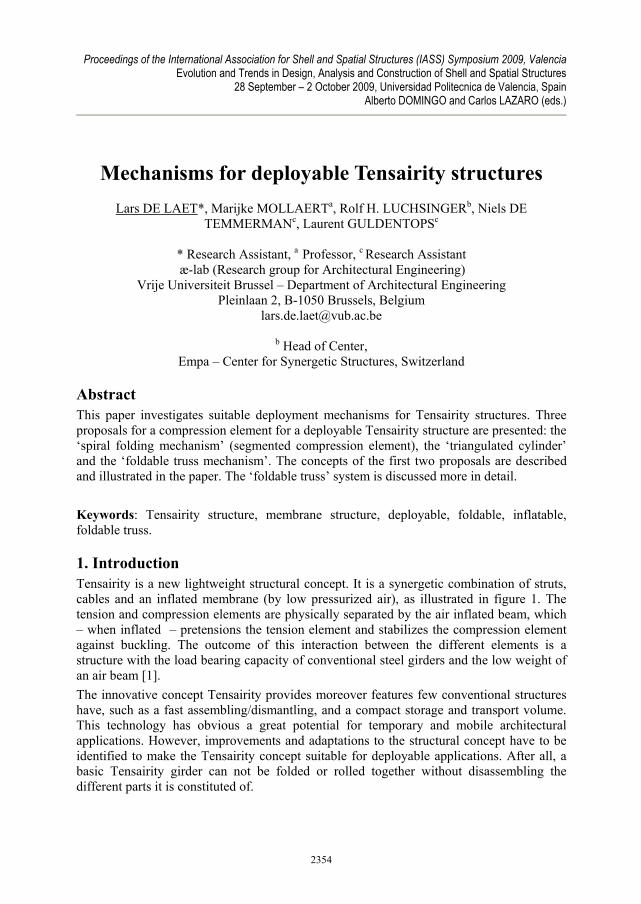
3. Mechanisms for deployable Tensairity As mentioned before, various kinds of mechanisms for a deployable Tensairity structure can be proposed. Using a compression element with low bending stiffness in deflated state is one solution. This way, the structure can be rolled or packed together as a whole when no internal overpressure is present. Such a solution is called a ‘flexible compression element’ and has already been investigated and discussed by the author in [2]. Various flexible proposals for the compression element, such as separate wooden segments, chains, hydraulic hoses etc., have been analyzed and evaluated by means of experiments on scale models (figure 2). Main conclusion of this research is that most of the investigated flexible compression elements have a poor load-bearing behaviour when placed inside the pocket of a Tensairity beam (in proportion to their complexity).
2355
Proceedings of the International Association for Shell and Spatial Structures (IASS) Symposium 2009, Valencia Evolution and Trends in Design, Analysis and Construction of Shell and Spatial Structures
Figure 2. Flexible compression element: overview of investigated proposals
Currently, three proposals for a deployable Tensairity structure are being investigated in this research, the ‘segmented compression element’, the ‘triangulated cylinder’ and the ‘foldable truss structure’. The first and second proposals are currently at conceptual stage and will be presented briefly in the next sections. The latter will be discussed more in detail further in this paper.
4. Segmented compression element
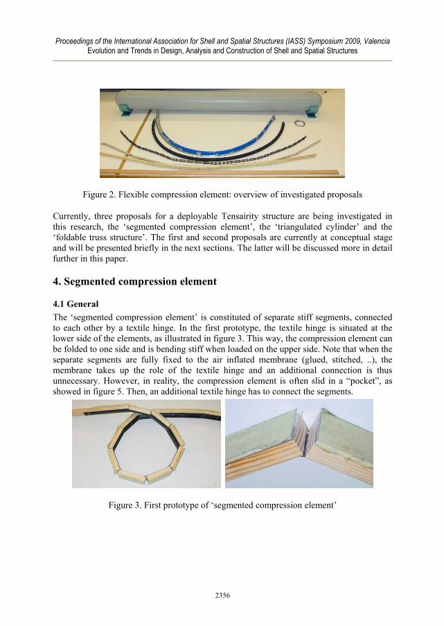
4.1 General The ‘segmented compression element’ is constituted of separate stiff segments, connected to each other by a textile hinge. In the first prototype, the textile hinge is situated at the lower side of the elements, as illustrated in figure 3. This way, the compression element can be folded to one side and is bending stiff when loaded on the upper side. Note that when the separate segments are fully fixed to the air inflated membrane (glued, stitched, ..), the membrane takes up the role of the textile hinge and an additional connection is thus unnecessary. However, in reality, the compression element is often slid in a “pocket”, as showed in figure 5. Then, an additional textile hinge has to connect the segments.
Figure 3. First prototype of ‘segmented compression element’
2356

Proceedings of the International Association for Shell and Spatial Structures (IASS) Symposium 2009, Valencia Evolution and Trends in Design, Analysis and Construction of Shell and Spatial Structures
Figure 4. Deployable Tensairity beam with the ‘segmented compression element’
Figure 5. Detail of ‘segmented compression element’ – folded and unfolded
When the Tensairity beam is loaded with a distributed load, the upper elements are in full compression. Thus, the fabric hinge is theoretically not necessary. However, previous research showed that the presence of the fabric hinge improves the load-bearing behaviour significant [2]. A first reason is that the hinge eliminates play between the elements. This way, immediate contact between the different segmented elements occurs when the structure is loaded. This is not the case when unconnected separate elements are used. A second motivation for using a (fabric) hinge is that this connection improves the ability of the compression element to take up local shear forces. If no hinge would be present, the segments would shift with respect to each other. A third argument for using a hinge is the increased bending stiffness of the ‘compression’ element when the elements are connected with each other. After all, when high deformations occur, the ‘compression element’ will bend and have a certain part of its section in tension. The fabric is able to bear the tension forces resulting from the bending stresses. The part of the segments that has to take up high compression forces is reinforced with aluminium plates. The bending stiffness increases with increasing the distance between the hinge and the aluminium plate.
4.2 Folding As mentioned before, the ‘segmented compression element’ folds only in one direction; the hinge is always situated at the side of the inflated beam (figure 5). The reason is that the membrane of the airbeam can not overstretch, as mentioned in section 2. The ‘segmented compression element’ can therefore only be positioned at one side of the Tensairity beam.
2357

Proceedings of the International Association for Shell and Spatial Structures (IASS) Symposium 2009, Valencia Evolution and Trends in Design, Analysis and Construction of Shell and Spatial Structures
This concept is thus not suitable for applications where the direction of the loading can change (e.g. wind pressure and suction), because this implies that the Tensairity beam should have compression elements at both sides of the beam, which is not the case with this solution for a deployable Tensairity structure (figure 6).
Figure 6. Compression element only at one side of the Tensairity beam
The deployable Tensairity beam with ‘segmented compression element’ can be folded in different ways, as illustrated in figure 7. One way of folding is called the ‘loop-folding’ (figure 7a). This implicates that all segments have different lengths, which is not desirable from a manufacturing point of view. This would also increase the size and amounts of segments and thus the amount of hinges, which would weaken the structure too much. Note the space between the different loops in figure 7a for ‘accommodating’ the membrane. Another way of folding is called the ‘closed-loop’ folding (figure 7b). Here, the structure is folded until one loop is reached. The advantage of this proposal is that every segment has the same length. On the other hand, the radius of the packaging becomes very large in the case of long beams. A solution for folding the Tensairity beam where all segments can have the same length and where the folding is independent of the length of the Tensairity beam is called the ‘spiral folding mechanism’. This mechanism is a modified ‘closed-loop’ folding system: the hinge between the segments is inclined. This way, the mechanism will have the shape of a spiral in folded position (figure 7c).
Figure 7. Different folding possibilities: a. loop-folding, b. closed-loop folding, c. spiral folding mechanism
The designer chooses the length of the segments, the number of sides of one loop (polygon) and the distance between two loops. (The radius of the packaging (spiral) can also be chosen instead of the length of the segments.) By then solving the equation below, one finds the angle α between the hinge and the longitudinal direction, as illustrated in figure 8.
2358

Proceedings of the International Association for Shell and Spatial Structures (IASS) Symposium 2009, Valencia Evolution and Trends in Design, Analysis and Construction of Shell and Spatial Structures
Figure 8. Determination of the angle α
In deflated state, the mechanism is folded in a spiral configuration. The stability of this packaging is guaranteed by using tapered segments and a fabric hinge at the starting point of the tapering (figure 9). This system is currently in development. No experiments have been conducted yet on this mechanism. Figure 9 shows the mechanism of the second prototype for the deployable Tensairity beam with ‘segmented compression element’.
Figure 9. left: tapered compression elements; right: detail, with fabric hinge in red
5. Triangulated cylinder A second proposal for a deployable Tensairity beam – still in conceptual design stage – is inspired by the concept of the folding of ‘triangulated cylinders’. This folding ‘system’ consists of identical triangular panels on a helical strip, which fold according to a predefined folding pattern to a compact stack of plates (figure 10). The folding properties of the cylinder are dependent of the various chosen parameters, as discussed thoroughly in [3]. The main advantage of this mechanism is the neat and controlled folding of the membrane according to a predefined folding pattern. After all, a membrane (e.g. PVC polyester) has a certain amount of bending stiffness which makes the folding difficult when it is packed together randomly to a ‘bunch’.
2359
Proceedings of the International Association for Shell and Spatial Structures (IASS) Symposium 2009, Valencia Evolution and Trends in Design, Analysis and Construction of Shell and Spatial Structures
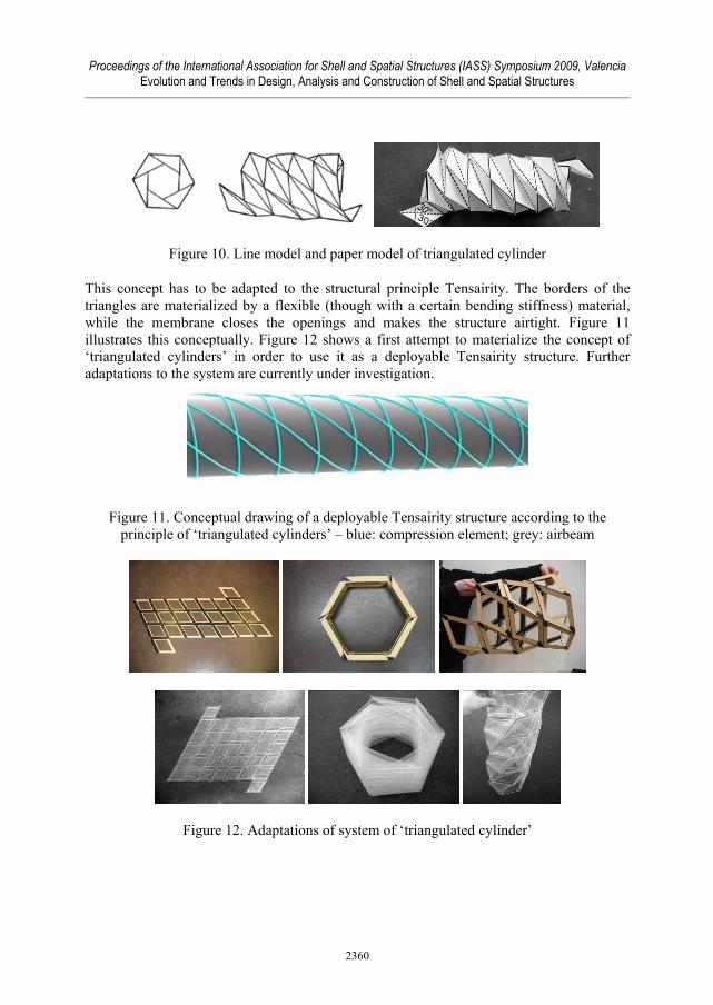
Figure 10. Line model and paper model of triangulated cylinder
This concept has to be adapted to the structural principle Tensairity. The borders of the triangles are materialized by a flexible (though with a certain bending stiffness) material, while the membrane closes the openings and makes the structure airtight. Figure 11 illustrates this conceptually. Figure 12 shows a first attempt to materialize the concept of ‘triangulated cylinders’ in order to use it as a deployable Tensairity structure. Further adaptations to the system are currently under investigation.
Figure 11. Conceptual drawing of a deployable Tensairity structure according to the principle of ‘triangulated cylinders’ – blue: compression element; grey: airbeam
Figure 12. Adaptations of system of ‘triangulated cylinder’
2360

Proceedings of the International Association for Shell and Spatial Structures (IASS) Symposium 2009, Valencia Evolution and Trends in Design, Analysis and Construction of Shell and Spatial Structures
6. Foldable truss mechanism
6.1 General The “foldable truss” is a conventional truss where the horizontal tension and compression bars are divided in two and reconnected with an intermediate hinge (figure 13). This way, the truss becomes a mechanism. The compression and tension bars are in the deployable Tensairity structure continuously attached with the hull, and this way, the truss is stable when the air beam is fully inflated. The diagonals can be included or excluded and vertical cables connecting upper and lower strut can be applied [4].
Figure 13. The foldable truss mechanism – upper: modification of a conventional truss; lower: adapted foldable truss for using it in a deployable Tensairity beam
In figure 14, a sequence of a deployable Tensairity structure with the ‘foldable truss’ mechanism is shown. It is clear that this mechanism has some potential. However, this solution can still be improved and a series of iterative optimizations have to be conducted, as well from a kinematic as from a structural point a view.
Figure 14. Folding sequence of deployable Tensairity beam with foldable truss mechanism
6.2 Experimental investigation Before improving the structural behaviour of the structure, it is important to fully understand the load-bearing behaviour of this structure. Therefore, some experiments on a two meter long statically determined deployable Tensairity beam were conducted. Various configurations are tested in order to reveal the influence of the different parameters on the load bearing behaviour, such as the presence and configuration of pretensioned cables that connect the upper and lower hinges. The investigated configurations are illustrated in figure
2361

Proceedings of the International Association for Shell and Spatial Structures (IASS) Symposium 2009, Valencia Evolution and Trends in Design, Analysis and Construction of Shell and Spatial Structures
15. In [2], the experimental set-up is described in detail and some first results were given. The final results are briefly summarized below.
Figure 15. Investigated configurations
- Load cycles When the deployable Tensairity beam is loaded, the fabric adapts to the new load condition during the first load cycle. The load-displacement responses of the second and third load cycle are almost identical (figure 16). The deflections of the third cycle are noted. The Tensairity girder shows a pronounced hysteresis indicating energy dissipation [5].
Figure 16. Load-displacement response of three load cycles
- Influence of internal pressure The internal pressure of the beam was varied during the experiments. The deflections of various configurations were measured with an internal pressure of 75, 100 and 125 mbars. The results reveal the influence of the internal pressure of Tensairity beams on the load-bearing behaviour. There can be concluded that the stiffness of the structure is increased with increasing pressure, just like it is the case for a regular Tensairity beam. After all, a higher pressure and thus a more pretensioned membrane leads to a more constant spacing between tension and compression element. Moreover, the friction between the pocket and the compression element increases with higher pressure values, which results in a stiffer structure.
2362

Proceedings of the International Association for Shell and Spatial Structures (IASS) Symposium 2009, Valencia Evolution and Trends in Design, Analysis and Construction of Shell and Spatial Structures
- Influence of (number of) hinges The load-displacement response of case 1 and 2 for a distributed load is investigated and illustrated in figure 17a. The central displacement at the tension chord is given on the X-axis, the Y-axis represents the amount of load. Both configurations have quite similar deflections under the same load and thus similar stiffness, despite the different number of hinges. The presence and influence of the middle hinge on the stiffness is thus much greater than that of the other hinges. These conclusions are valid for all three investigated load cases. - Influence of configuration of pre-stressed cables that connect the hinges on compression and tension side Figure 17a shows the load-displacement diagram under distributed load of the different deployable Tensairity beam configurations (at the third load cycle). The deflection at the middle point on the upper compression element is plotted on the X-axis; the Y-axis represents the applied load. Figure 17b represents the deflection of the upper strut of all investigated configurations. It can be seen that the configuration of internal cables has an influence on the load-bearing behaviour, since every case has a different stiffness. Case 1, the configuration without any internal cable shows the biggest deflection; case 6 is the stiffest configuration. It is remarkable that the deflections under a point load and an asymmetric load are analogue; the ‘ranking’ of the different cases is the same. Current research is analysing these results thoroughly to identify the load-transfer between the different elements of the Tensairity structure and to determine what the most optimal configuration is.
Figure 17a. Load-displacement in the middle of compression chord for the various configurations; b.Final(scaled) position of hinges of various configurations at maximal load
6.3 Optimization of the shape Not only the internal pressure and the configurations of internal prestressed cables influence the stiffness of the structure. Also the form of a Tensairity structure can be altered to change the stiffness. The cylindrical Tensairity beam consisting of a single linear
2363

Proceedings of the International Association for Shell and Spatial Structures (IASS) Symposium 2009, Valencia Evolution and Trends in Design, Analysis and Construction of Shell and Spatial Structures
compression element and two spiraled cables (figure 1) is the simplest one, but, as it turns out, not the most efficient one. Research pointed out, by means of theoretical and numerical results, that shapes with a curved compression element (spindle shapes) are more efficient than the cylindrical [6]. Figure 18 shows an evaluation of different shapes by means of a load-deflection graph. Consequently, efforts are currently made to develop a deployable spindle shaped Tensairity structure (figure 19).
Figure 18. Evaluation of different shapes by means of load-deflection graph [6]
Figure 19. Investigations on a spindle shaped deployable Tensairity beam
2364

Proceedings of the International Association for Shell and Spatial Structures (IASS) Symposium 2009, Valencia Evolution and Trends in Design, Analysis and Construction of Shell and Spatial Structures
7. Conclusions Identifying deployment mechanisms for Tensairity structures will widen the range of appli-cations where these lightweight structures will be used, especially as structural efficient solution for temporary and mobile constructions. The exploration and analysis of ideas for deployable systems by means of experiments on scale models is the recommended method to evaluate proposals and gain understanding of the influence of different parameters. Three proposals for a compression element for a deployable Tensairity structure were presented: the ‘spiral folding mechanism’ (segmented compression element), the ‘triangulated cylinder’ and the ‘foldable truss’ mechanism. The concepts of the first two proposals, which are currently being developed more in detail, are described in the paper. The ‘foldable truss’ system is investigated more thoroughly in this paper. By investigating the foldable truss system, there could be revealed that the arrangement of cables has an influence on the stiffness of the deployable Tensairity beam, just like the pretension in the cables. These results will provide the basis for a proposal of an optimised deployment mechanism for the deployable (spindle shaped) Tensairity structure. The challenge is now to improve the promising proposals by making them more efficient. An in-depth investigation on the kinematic aspects of the deployable Tensairity beam, like the hinges and the folding of the membrane, is as well an important task of current and future research.
Acknowledgement This research is funded by the Research Foundation – Flanders (FWO).
References [1] Luchsinger, R. H., et al., “The new structural concept Tensairity: Basic principles.”,
in A. Zingoni (ed.), Proceedings of the Second International Conference on Structural Engineering, Mechanics and Computation. Lisse (The Netherlands): A.A. Balkema/Swets Zeitlinger, 2004.
[2] De Laet, L. et al., “Deployable Tensairity Structures”, in J. Salinas (ed.), Proceedings of the International Symposium on New materials and technologies, new designs and innovations: IASS, Acapulco (Mexico), 2008.
[3] Guest, S. D. et al., “The Folding of Triangulated Cylinders, Part I: Geometric Considerations.” ASME Journal of Applied Mechanics, 61(4), pp. 773-777, 1994.
[4] Luchsinger, R. H. “Collapsible Pneumatically Stabilised Supports“, EP1861567. [5] Luchsinger, R. H. et al., “The role of fabrics in Tensairity.” Proceedings of the
International Symposium on New Perspectives for Shell and Spatial Structures: International Association for Shell and Spatial Structures, Beijing (China), 2006.
[6] Pedretti, A. et al., “The new structural concept Tensairity: FE-modeling and applications.”, in A. Zingoni (ed.), Proceedings of the Second International Conference on Structural Engineering, Mechanics and Computation. Lisse (The Netherlands): A.A. Balkema/Swets Zeitlinger, 2004.
2365