
technical data -...
27
air conditioning systems EEDEN09-203 technical data Air-cooled selection procedure
Transcript of technical data -...
air conditioning systems
EEDEN09-203
technical data
Air-cooled selection procedure

Air-cooled selection procedure
EEDEN09-203
air conditioning systems
technical data

• VRV® Systems • Air-cooled selection procedure 1
• Air-cooled selection procedure
1 Selection procedure VRV®III-C system based on heating load . 2Indoor unit selection . . . . . . . . . . . . . . . . . . . . . . . . . . . . . . . . . . . . . . . . . . . . . . . . . . 2Outdoor unit selection . . . . . . . . . . . . . . . . . . . . . . . . . . . . . . . . . . . . . . . . . . . . . . . . 2Actual performance data . . . . . . . . . . . . . . . . . . . . . . . . . . . . . . . . . . . . . . . . . . . . . 3Selection example based on heating load . . . . . . . . . . . . . . . . . . . . . . . . . . . 3
2 Capacity correction ratio. . . . . . . . . . . . . . . . . . . . . . . . . . . . . . . . . . . . . . . . . . . 5VRV®III-C . . . . . . . . . . . . . . . . . . . . . . . . . . . . . . . . . . . . . . . . . . . . . . . . . . . . . . . . . . . . 5
3 Integrated heating capacity . . . . . . . . . . . . . . . . . . . . . . . . . . . . . . . . . . . . . . . 9
4 Refnet pipe systems . . . . . . . . . . . . . . . . . . . . . . . . . . . . . . . . . . . . . . . . . . . . . . 10
5 Example of Refnet piping layouts . . . . . . . . . . . . . . . . . . . . . . . . . . . . . . . 20
6 Refrigerant pipe selection . . . . . . . . . . . . . . . . . . . . . . . . . . . . . . . . . . . . . . . . 21VRV®III-C . . . . . . . . . . . . . . . . . . . . . . . . . . . . . . . . . . . . . . . . . . . . . . . . . . . . . . . . . . . 21Piping thickness . . . . . . . . . . . . . . . . . . . . . . . . . . . . . . . . . . . . . . . . . . . . . . . . . . . . . 24
TABLE OF CONTENTSII Air-cooled selection procedure

• Air-cooled selection procedure
• VRV® Systems • Air cooled selection procedure2
3
1 Selection procedure VRV®III-C system based on heating load1 - 1 Indoor unit selection
Enter indoor unit capacity tables at given indoor and outdoor temperature.
Select the unit that the capacity is the nearest to and higher than the given load.
NOTE
1 Individual indoor unit capacity is subject to change by the combination. Actual capacity has to be calculated according to the combination by using outdoor units capacity table.
1 - 2 Outdoor unit selection
Allowable combinations are indicated in indoor unit combination total capacity index table.
In general, oudoor units can be selected as follows though the location of the unit, zoning and usage of the rooms should be considered.
The indoor and outdoor unit combination is determined that the sum of indoor unit capacity index is nearest to and smaller than the capacity index at 100 % combination ratio of each outdoor unit. Up to 32 indoor units can be connected to one outdoor unit. It is recommended to choose a larger outdoor unit if the installation space is large enough.
If the combination ratio is higher than 100 %, the indoor unit selection will have to be reviewed by using actual capacity of each indoor unit.
Indoor unit combination total capacity index table
Indoor unit capacity index
Outdoor unit Indoor unit combination ratio130 % 120 % 110 % 100 % 90 % 80 % 70% 60 % 50 %
RTSYQ10PY1 325 300 275 250 225 200 175 150 125RTSYQ14PY1 455 420 385 350 315 280 245 210 175RTSYQ16PY1 520 480 440 400 360 320 280 240 200RTSYQ20PY1 650 600 550 500 450 400 350 300 250
Model 20 25 32 40 50 63 71 80 100 125 200 250Capacity index 20 25 31.25 40 50 62.5 71 80 100 125 200 250

• VRV® Systems • Air cooled selection procedure 3
• Air-cooled selection procedure
3
1 Selection procedure VRV®III-C system based on heating load1 - 3 Actual performance data
Use outdoor unit capacity tables
Determine the correct table according to the outdoor unit model and combination ratio.
Enter the table at given indoor and outdoor temperature and find the outdoor capacity and power input. The individual indoor unit capacity (power input) can be calculated as follows:
ICA = OCA x INXTNX
ICA: Individual indoor unit capacity (power input)OCA: Outdoor unit capacity (power input)INX: Individual indoor unit capacity indexTNX: Total capacity index
Then, correct the indoor unit capacity according to the piping length.If the corrected capacity is smaller than the load, the size of indoor unit has to be increased. Repeat the same selection procedure.
1 - 4 Selection example based on heating load1 Given
• Design conditionheating: indoor 20°CWB, outdoor -9.5°CDB, -10.0°CWB
• heating load
• Power supply: 3-phase 380V/50Hz
2 Indoor unit selection
Select indoor type: duct, cassette, floor standing, ...
We select the roundflow cassette (FXFQ-P)
Select indoor unit size using indoor capacity tables.
Conditions: indoor 20°CWB, outdoor -9.5°CDB, -10.0°CWBSelection results are as follows:
• Calculate total indoor unit capacity index: 2 x 25 + 1 x 31.25 + 2 x 40 + 2 x 50 + 1 x 62.5 = 323.75
3 Outdoor unit selection
Select outdoor unit type: Heat Recovery, Heat Pump, ...
Here we select VRV®III-C
Total capacity index of indoor units = 323.75
Select outdoor unit where total capacity index is 375 close to 100% connection ratio.
Calculate actual connection ratio:
RTSQ10P: 250 at 100 % -> 323.75 / 250 = 129.5%
RTSQ14P: 350 at 100 % -> 323.75 / 350 = 92.5 %.
Because of the high heating capacity of the cold region VRV®, we can make a selection close to 130% connection ratio.
Calculate outdoor capacity.
RTSQ10P at 130% at design conditions: 28.4
RTSQ10P at 120% at design conditions: 28.3
Interpolate:
28.3 ? 28.4
300 323.75 325
28.3 + (28.4 - 28.3) / (325-300) x (323.75-300) = 28.395
Room A B C D E F G HLoad (kW) 2.2 2.1 5.5 4.0 3.5 2.6 3.5 4.2
Room A B C D E F G HLoad (kW) 2.2 2.1 5.5 4.0 3.5 2.6 3.5 4.2Unit size 25 25 63 50 40 32 40 50Capacity 2.4 2.4 6.1 4.8 3.8 3.1 3.8 4.8
• Air-cooled selection procedure
• VRV® Systems • Air cooled selection procedure4
3
1 Selection procedure VRV®III-C system based on heating load1 - 4 Selection example based on heating load
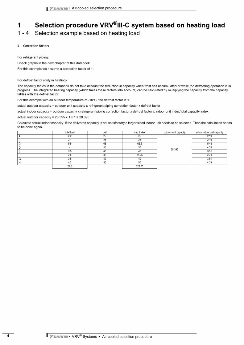
4 Correction factors
For refrigerant piping:
Check graphs in the next chapter of this databook.
For this example we assume a correction factor of 1.
For defrost factor (only in heating):
The capacity tables in the databook do not take account the reduction in capacity when frost has accumulated or while the defrosting operation is in progress. The integrated heating capacity (which takes these factors into account) can be calculated by multiplying the capacity from the capacity tables with the defrost factor.
For this example with an outdoor temperature of -10°C, the defrost factor is 1.
actual outdoor capacity = outdoor unit capacity x refrigerant piping correction factor x defrost factor
actual indoor capacity = outdoor capacity x refrigerant piping correction factor x defrost factor x indoor unit index/total capacity index
actual outdoor capacity = 28.395 x 1 x 1 = 28.395
Calculate actual indoor capacity. If the delivered capacity is not satisfactory a larger sized indoor unit needs to be selected. Than the calculation needs to be done again.
total load unit cap. Index outdoor unit capacity actual indoor unit capacityA 2.2 25 25
28.395
2.19B 2.1 25 25 2.19C 5.5 63 62.5 5.48D 4 50 50 4.39E 3.5 40 40 3.51F 2.6 32 31.25 2.74G 3.5 40 40 3.51H 4.2 50 50 4.39
27.6 323.75

• VRV® Systems • Air cooled selection procedure 5
• Air-cooled selection procedure
3
2 Capacity correction ratio2 - 1 VRV®III-C
RTSYQ10PY1
• Rate of change in cooling capacity • Rate of change in heating capacity
3D060819
NOTES
1 These figures illustrate the rate of change in capacity of a standard indoor unit system at maximum load (with the thermostat set to maximum) under standard conditions.
Moreover, under partial load conditions there is only a minor deviation from the rate of change in capacity shown in the above figures.
2 With this outdoor unit, evaporating pressure constant control when cooling, and condensing pressure constant control when heating is carried out.
3 Method of calculating A/C (cooling / heating) capacity:
The maximum A/C capacity of the system will be either the total A/C capacity of the indoor units obtained from capacity characteristics table or the maximum A/C capacity of outdoor
units as mentioned below, wichever smaller.
Calculating A/C capacity of outdoor units
• Condition: Indoor unit combination ratio does not exceed 100%
Maximum A/C capacity of outdoor units = A/C capacity of outdoor units obtained from capacity characteristic table at the 100% combination
x Capacity change rate due to piping length to the farthest indoor unit
• Condition: Indoor unit combination ratio exceeds 100%
Maximum A/C capacity of outdoor units = A/C capacity of outdoor units obtained from capacity characteristic table at the combination
x Capacity change rate due to piping length to the farthest indoor unit
4 When overall equivalent pipe length is 90m or more, the diameter of the main gas and liquid pipes (outdoor unit-branch sections) must be increased. (Consider the equivalent pipe length of
function unit as 6mm)
Diameter of above case
❈If available on the site, use this size. Otherwise, not increased.
5 Read cooling/heating capacity rate of change in the above figures based on the following equivalent length.
Overall equivalent length =
(Equivalent length to main pipe) x correction factor + (equivalent length after branching)
Choose a correction factor from the following table.
When cooling capacity is calcurated: gas pipe size
When heating capacity is calcurated: liquid pipe size.
In the above case
(Cooling) Overall equivalent length = 80mx0.5+40m=80m
(Heating) Overall equivalent length = 80mx0.2+40m=56m
The rete of change in cooling capacity when Hp=0m is thus approximatly 0.87
heating capacity when Hp=0m is thus approximatly 1.0
EXPLANATION OF SYMBOLS
Hp : Level difference (m) between indoor and outdoor units where indoor unit in inferior position
HM : Level difference (m) between indoor and outdoor units where indoor unit in superior position
L : Equivalent pipe length (m)
α : Rete of change in cooling/heating capacity
[Diameter of the main pipes (standard size)]
[Temper grade and thickness]
Model gas liquid
RTSYQ10PY1(E)ø 25.4 ❈ ø 12.7
Rate of change
(object piping)
correction factor
standard size Size increase
Cooling (gas pipe) 1.0 0.5
Heating (liquid pipe) 1.0 0.7
Model gas liquid
RTSYQ10PY1 (E) ø 22.2 ø 9.5
Temper grade 0 Type 1/2H Type
Outer diameter ø 9.5 ø 12.7 ø 22.2 ø 25.4
Minimum wall thickness 0.80 0.80 0.80 0.88
Overall equivalent pipe length
Outdoor
unit
Function
unitBranch
Indoor unit
Equivalent length Equivalent length
Outdoor
unit
Indoor unit
BranchGas pipe: size increase
liquid pipe: size increaseFunction
unit

• Air-cooled selection procedure
• VRV® Systems • Air cooled selection procedure6
3
2 Capacity correction ratio2 - 1 VRV®III-C
RTSYQ14PY1
• Rate of change in cooling capacity • Rate of change in heating capacity
3D060820
NOTES
1 These figures illustrate the rate of change in capacity of a standard indoor unit system at maximum load (with the thermostat set to maximum) under standard conditions.
Moreover, under partial load conditions there is only a minor deviation from the rate of change in capacity shown in the above figures.
2 With this outdoor unit, evaporating pressure constant control when cooling, and condensing pressure constant control when heating is carried out.
3 Method of calculating A/C (cooling / heating) capacity:
The maximum A/C capacity of the system will be either the total A/C capacity of the indoor units obtained from capacity characteristics table or the maximum A/C capacity of outdoor
units as mentioned below, wichever smaller.
Calculating A/C capacity of outdoor units
• Condition: Indoor unit combination ratio does not exceed 100%
Maximum A/C capacity of outdoor units = A/C capacity of outdoor units obtained from capacity characteristic table at the 100% combination
x Capacity change rate due to piping length to the farthest indoor unit
• Condition: Indoor unit combination ratio exceeds 100%
Maximum A/C capacity of outdoor units = A/C capacity of outdoor units obtained from capacity characteristic table at the combination
x Capacity change rate due to piping length to the farthest indoor unit
4 When overall equivalent pipe length is 90m or more, the diameter of the main gas and liquid pipes (outdoor unit-branch sections) must be increased. (Consider the equivalent pipe length of
function unit as 6mm)
Diameter of above case
5 Read cooling/heating capacity rate of change in the above figures based on the following equivalent length.
Overall equivalent length =
(Equivalent length to main pipe) x correction factor + (equivalent length after branching)
Choose a correction factor from the following table.
When cooling capacity is calcurated: gas pipe size
When heating capacity is calcurated: liquid pipe size.
In the above case
(Cooling) Overall equivalent length = 80mx1.0+40m=120m
(Heating) Overall equivalent length = 80mx0.3+40m=64m
The rete of change in cooling capacity when Hp=0m is thus approximatly 0.88
heating capacity when Hp=0m is thus approximatly 1.0
EXPLANATION OF SYMBOLS
Hp : Level difference (m) between indoor and outdoor units where indoor unit in inferior position
HM : Level difference (m) between indoor and outdoor units where indoor unit in superior position
L : Equivalent pipe length (m)
α : Rete of change in cooling/heating capacity
[Diameter of the main pipes (standard size)]
[Temper grade and thickness]
Model gas liquid
RTSYQ14PY1(E) not increased ø 15.9
Rate of change
(object piping)
correction factor
standard size Size increase
Cooling (gas pipe) 1.0 /
Heating (liquid pipe) 1.0 0.3
Model gas liquid
RTSYQ14PY1 (E) ø 28.6 ø 12.7
Temper grade 0 Type 1/2H Type
Outer diameter ø 12.7 ø 15.9 ø 28.6
Minimum wall thickness 0.80 0.99 0.99
Overall equivalent pipe length
Outdoor
unit
Function
unitBranch
Indoor unit
Equivalent length Equivalent length
Outdoor
unit
Indoor unit
BranchGas pipe: size increase
liquid pipe: size increaseFunction
unit

• VRV® Systems • Air cooled selection procedure 7
• Air-cooled selection procedure
3
2 Capacity correction ratio2 - 1 VRV®III-C
RTSYQ16PY1
• Rate of change in cooling capacity • Rate of change in heating capacity
3D060821
NOTES
1 These figures illustrate the rate of change in capacity of a standard indoor unit system at maximum load (with the thermostat set to maximum) under standard conditions.
Moreover, under partial load conditions there is only a minor deviation from the rate of change in capacity shown in the above figures.
2 With this outdoor unit, evaporating pressure constant control when cooling, and condensing pressure constant control when heating is carried out.
3 Method of calculating A/C (cooling / heating) capacity:
The maximum A/C capacity of the system will be either the total A/C capacity of the indoor units obtained from capacity characteristics table or the maximum A/C capacity of outdoor
units as mentioned below, wichever smaller.
Calculating A/C capacity of outdoor units
• Condition: Indoor unit combination ratio does not exceed 100%
Maximum A/C capacity of outdoor units = A/C capacity of outdoor units obtained from capacity characteristic table at the 100% combination
x Capacity change rate due to piping length to the farthest indoor unit
• Condition: Indoor unit combination ratio exceeds 100%
Maximum A/C capacity of outdoor units = A/C capacity of outdoor units obtained from capacity characteristic table at the combination
x Capacity change rate due to piping length to the farthest indoor unit
4 When overall equivalent pipe length is 90m or more, the diameter of the main gas and liquid pipes (outdoor unit-branch sections) must be increased. (Consider the equivalent pipe length of
function unit as 6m)
Diameter of above case
❈If available on the site, use this size. Otherwise, not increased.
5 Read cooling/heating capacity rate of change in the above figures based on the following equivalent length.
Overall equivalent length =
(Equivalent length to main pipe) x correction factor + (equivalent length after branching)
Choose a correction factor from the following table.
When cooling capacity is calcurated: gas pipe size
When heating capacity is calcurated: liquid pipe size.
In the above case
(Cooling) Overall equivalent length = 80mx0.5+40m=80m
(Heating) Overall equivalent length = 80mx0.3+40m=64m
The rete of change in cooling capacity when Hp=0m is thus approximatly 0.88
heating capacity when Hp=0m is thus approximatly 1.0
EXPLANATION OF SYMBOLS
Hp : Level difference (m) between indoor and outdoor units where indoor unit in inferior position
HM : Level difference (m) between indoor and outdoor units where indoor unit in superior position
L : Equivalent pipe length (m)
α : Rete of change in cooling/heating capacity
[Diameter of the main pipes (standard size)]
[Temper grade and thickness]
Model gas liquid
RTSYQ16PY1(E) ø 31.8 ❈ ø 15.9
Rate of change
(object piping)
correction factor
standard size Size increase
Cooling (gas pipe) 1.0 0.5
Heating (liquid pipe) 1.0 0.3
Model gas liquid
RTSYQ16PY1 (E) ø 28.6 ø 12.7
Temper grade 0 Type 1/2H Type
Outer diameter ø 12.7 ø 15.9 ø 28.6 ø 31.8
Minimum wall thickness 0.80 0.99 0.99 1.10
Overall equivalent pipe length
Outdoor
unit
Function
unitBranch
Indoor unit
Equivalent length Equivalent length
Outdoor
unit
Indoor unit
BranchGas pipe: size increase
liquid pipe: size increaseFunction
unit
• Air-cooled selection procedure
• VRV® Systems • Air cooled selection procedure8
3
2 Capacity correction ratio2 - 1 VRV®III-C
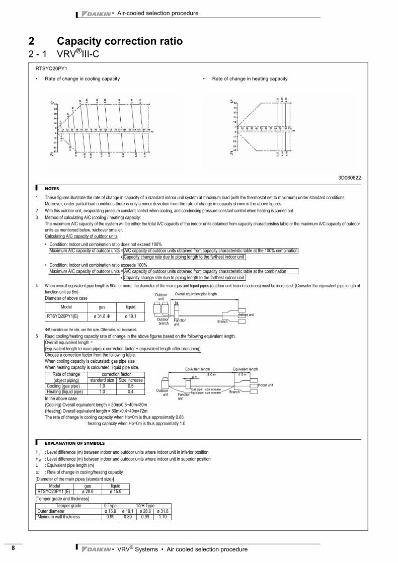
RTSYQ20PY1
• Rate of change in cooling capacity • Rate of change in heating capacity
3D060822
NOTES
1 These figures illustrate the rate of change in capacity of a standard indoor unit system at maximum load (with the thermostat set to maximum) under standard conditions.
Moreover, under partial load conditions there is only a minor deviation from the rate of change in capacity shown in the above figures.
2 With this outdoor unit, evaporating pressure constant control when cooling, and condensing pressure constant control when heating is carried out.
3 Method of calculating A/C (cooling / heating) capacity:
The maximum A/C capacity of the system will be either the total A/C capacity of the indoor units obtained from capacity characteristics table or the maximum A/C capacity of outdoor
units as mentioned below, wichever smaller.
Calculating A/C capacity of outdoor units
• Condition: Indoor unit combination ratio does not exceed 100%
Maximum A/C capacity of outdoor units = A/C capacity of outdoor units obtained from capacity characteristic table at the 100% combination
x Capacity change rate due to piping length to the farthest indoor unit
• Condition: Indoor unit combination ratio exceeds 100%
Maximum A/C capacity of outdoor units = A/C capacity of outdoor units obtained from capacity characteristic table at the combination
x Capacity change rate due to piping length to the farthest indoor unit
4 When overall equivalent pipe length is 90m or more, the diameter of the main gas and liquid pipes (outdoor unit-branch sections) must be increased. (Consider the equivalent pipe length of
function unit as 6m)
Diameter of above case
❈If available on the site, use this size. Otherwise, not increased.
5 Read cooling/heating capacity rate of change in the above figures based on the following equivalent length.
Overall equivalent length =
(Equivalent length to main pipe) x correction factor + (equivalent length after branching)
Choose a correction factor from the following table.
When cooling capacity is calcurated: gas pipe size
When heating capacity is calcurated: liquid pipe size.
In the above case
(Cooling) Overall equivalent length = 80mx0.5+40m=80m
(Heating) Overall equivalent length = 80mx0.4+40m=72m
The rete of change in cooling capacity when Hp=0m is thus approximatly 0.88
heating capacity when Hp=0m is thus approximatly 1.0
EXPLANATION OF SYMBOLS
Hp : Level difference (m) between indoor and outdoor units where indoor unit in inferior position
HM : Level difference (m) between indoor and outdoor units where indoor unit in superior position
L : Equivalent pipe length (m)
α : Rete of change in cooling/heating capacity
[Diameter of the main pipes (standard size)]
[Temper grade and thickness]
Model gas liquid
RTSYQ20PY1(E) ø 31.8 ❈ ø 19.1
Rate of change
(object piping)
correction factor
standard size Size increase
Cooling (gas pipe) 1.0 0.5
Heating (liquid pipe) 1.0 0.4
Model gas liquid
RTSYQ20PY1 (E) ø 28.6 ø 15.9
Temper grade 0 Type 1/2H Type
Outer diameter ø 15.9 ø 19.1 ø 28.6 ø 31.8
Minimum wall thickness 0.99 0.80 0.99 1.10
Branch
Overall equivalent pipe length
Outdoor
branchFunction
unit
Indoor unit
Equivalent length Equivalent length
Outdoor
unit
Indoor unit
BranchGas pipe: size increase
liquid pipe: size increaseFunction
unit
Outdoor
unit

• VRV® Systems • Air cooled selection procedure 9
• Air-cooled selection procedure
3
3 Integrated heating capacity
RTSYQ-P
INTEGRATED HEATING CAPACITY COEFFICIENT
The heating capacity tables do not take account of the reduction in capacity, when frost has accumulated or while the defrosting operation is in progress.
The capacity values, which take these factors into account, in other words, the integrated heating capacity values, can be calculated as follows:
Formula:
Integrated heating capacity = A
Value given in table of capacity characteristics = B
Integrated correction factor for frost accumulation = C
A = B x C
Integrating correction factor for finding integrated heating capacity
3TW27232-7
NOTE
1 The figure shows that the integrated heating capacity expresses the integrated capacity for a single cycle (from defrost operation to defrost
operation) in terms of time.
Please note that, when there is an accumulation of snow against the outside surface of the outdoor unit heat exchanger, there will always be a
temporary reduction in capacity, although this will of course vary in degree in accordance with a number of other factors, such as the outdoor
temperature (°CDB), relative humidity (RH) and the amount of frosting which occurs.
Outdoor Temperature° CDB (° CWB) -7 (-7.6) or less -5 (-5.6) -3 (-3.7) 0 (-0.7) 3 (2.2) 5 7 (6.0)
Correction factor defrost 0.95 0.93 0.88 0.85 0.86 0.90 1.00
Defrosting operationDefrosting operation
1 cycle
-
+
0
He
atin
g c
ap
acity
Time

• Air-cooled selection procedure
• VRV® Systems • Air cooled selection procedure10
3
4 Refnet pipe systems
1TW25799-4C
Liquid side junction Discharge gas side junction Suction gas side junction
I.D.J9.52
I.D.J12.70
I.D.J12.70I.D.J19.10
I.D.J10
I.D.J12.70
I.D.J15.90
I.D.J9.52
I.D.J15.90
I.D.J12.70
I.D.J12.70
I.D.J6.35
I.D.J6.35
I.D.J9.52
I.D.J12.70
I.D.J9.52 I.D.J6.35
I.D.J9.52
I.D.J6.35
I.D.J9.52
I.D.J6.35
I.D.J9.52
I.D.J15.90
I.D.J9.52I.D.J12.70
I.D.J12.70
I.D.J12.70
I.D.J9.52
I.D.J15.90
I.D.J12.70
I.D.J12.70
I.D.J15.90I.D.J22.20
I.D.J15.90 I.D.J12.70
I.D.J19.10
I.D.J15.90
I.D.J12.70
I.D.J19.10
I.D.J19.10
I.D.J12.70
I.D.J19.10I.D.J12.70
I.D.J9.52
I.D.J15.90
I.D.J15.90
I.D.J15.90
I.D.J15.90
I.D.J12.70
I.D.J6.35
I.D.J19.10
I.D.J9.52
I.D.J6.35I.D.J9.52
I.D.J9.52
I.D.J6.35
I.D.J9.52
I.D.J12.70
I.D.J6.35
I.D.J9.52
I.D.J9.52
I.D.J12.70
I.D.J15.90
I.D.J12.70
I.D.J31.80
I.D.J19.10I.D.J15.90
I.D.J25.40
I.D.J22.20I.D.J15.90
I.D.J12.70
I.D.J19.10I.D.J31.80 I.D.J28.60
I.D.J25.40
I.D.J38.10
I.D.J25.40
I.D.J12.70I.D.J15.90
I.D.J31.80
I.D.J19.10
I.D.J31.80
I.D.J25.40
I.D.J44.50
I.D.J25.40
I.D.J19.10 I.D.J15.90
I.D.J15.90
I.D.J31.80
I.D.J12.70
I.D.J19.10
I.D.J15.90
I.D.J22.20
I.D.J15.90
I.D.J12.70
I.D.J15.90
I.D.J12.70
I.D.J15.90I.D.J12.70
I.D.J15.90
I.D.J25.40
I.D.J38.10
I.D.J28.60
I.D.J25.40 I.D.J19.10I.D.J15.90
I.D.J38.10
I.D.J15.90
I.D.J25.40
I.D.J31.80
I.D.J31.80
I.D.J38.10
I.D.J44.50
I.D.J25.40
I.D.J31.80
I.D.J12.70
I.D.J31.80
I.D.J15.90
I.D.J12.70
I.D.J25.40
I.D.J19.10I.D.J19.10
I.D.J22.20
I.D.J9.52
I.D.J31.80
I.D.J12.70
I.D.J28.60
I.D.J29.10 I.D.J15.90
I.D.J19.10
I.D.J15.90
I.D.J12.70
I.D.J19.10
I.D.J19.10
I.D.J15.90
I.D.J25.40
I.D.J25.40
I.D.J25.40
I.D.J15.90
I.D.J12.70
I.D.J38.10
I.D.J19.10
I.D.J15.90
I.D.J31.80
I.D.J25.40
I.D.J25.40
I.D.J12.70
I.D.J15.90
I.D.J15.90
I.D.J28.60
I.D.J31.80I.D.J25.40
I.D.J25.40
I.D.J19.10
I.D.J25.40
I.D.J19.10
I.D.J12.70
I.D.J15.90
I.D.J31.80
I.D.J22.20
I.D.J9.52
I.D.J28.60
I.D.J38.10
I.D.J15.90
I.D.J22.20
I.D.J38.10
I.D.J12.70
I.D.J31.80
I.D.J25.40
I.D.J19.10
O.D.J12.70I.D.J15.90
O.D.J19.10
I.D.J6.35
I.D.J6.35
Closed pipes
KHRQ
23M
29T9
KHRQ
23M
20T8
KHRP
23M
64T8
KHRP
23M
33T8
KHRQ
22M
75T8
KHRQ
22M
64T8
KHRQ
22M
20TA
8KH
RP22
M75
T8KH
RP22
M64
T8KH
RQ22
M29
T9KH
RP23
M75
T8KH
RQ58
T7KH
RQ23
M75
T8KH
RQ23
M64
T8
I.D.J15.90
I.D.J15.90I.D.J19.10 I.D.J22.20
I.D.J19.10I.D.J15.90
I.D.J19.10
I.D.J15.90
I.D.J09.52
I.D.J19.10
I.D.J6.35I.D.J9.52I.D.J12.70
I.D.J15.90I.D.J12.70
I.D.J12.70
I.D.J15.90
I.D.J19.10I.D.J22.20
I.D.J15.90I.D.J19.10
I.D.J9.52
I.D.J6.35I.D.J9.52I.D.J12.70
I.D.J15.90I.D.J15.90
I.D.J12.70
I.D.J12.70
I.D.J12.70I.D.J15.90
I.D.J19.10
I.D.J15.90 I.D.J12.70
I.D.J22.20I.D.J15.90
I.D.J19.10
I.D.J9.52
I.D.J12.70 I.D.J9.52
I.D.J9.52
I.D.J19.10
O.D.J6.35
O.D.J15.90
O.D.J9.52 O.D.J12.70
I.D.J28.60
I.D.J25.40
I.D.J28.60
I.D.J12.70I.D.J15.90I.D.J19.10
I.D.J19.10 I.D.J15.90
I.D.J9.52I.D.J6.35
I.D.J12.70 I.D.J9.52
I.D.J15.90 I.D.J19.10
I.D.J15.90I.D.J12.70
I.D.J9.52
I.D.J12.70
I.D.J19.10
I.D.J12.70I.D.J15.90
I.D.J9.52I.D.J12.70I.D.J15.90
I.D.J25.40 I.D.J22.20
I.D.J19.10
I.D.J19.10
I.D.J15.90
I.D.J12.70I.D.J15.90I.D.J19.10
I.D.J25.40
I.D.J28.60I.D.J31.80I.D.J25.40
I.D.J19.10
I.D.J15.90
I.D.J19.10
I.D.J19.10
I.D.J15.90
I.D.J19.10
I.D.J12.70
I.D.J15.90I.D.J19.10
I.D.J12.70
I.D.J25.40
I.D.J15.90I.D.J19.10
I.D.J28.60I.D.J31.80
I.D.J25.40
I.D.J28.60 I.D.J25.40
I.D.J15.90I.D.J19.10I.D.J25.40
I.D.J31.80I.D.J31.80I.D.J38.10
I.D.J15.90
I.D.J19.10
I.D.J15.90

• VRV® Systems • Air cooled selection procedure 11
• Air-cooled selection procedure
3
4 Refnet pipe systems
1TW25799-4C
Liquid side header Discharge gas side header Suction gas side header
I.D.J6.35 (6x)I.D.J6.35 (2x)
I.D.J15.90
I.D.J9.52 (6x)
I.D.J15.90
I.D.J9.52 (6x)
I.D.J15.90
I.D.J6.35 (6x)I.D.J6.35 (6x)
I.D.J15.90
I.D.J9.52 (8x)
I.D.J19.10I.D.J19.10
I.D.J15.90
I.D.J6.35 (6x)I.D.J9.52 (6x)I.D.J6.35 (2x)
I.D.J15.90
I.D.J9.52 (6x)I.D.J6.35 (6x)
I.D.J15.90
I.D.J6.35 (2x)
I.D.J15.90
I.D.J19.10
I.D.J9.52 (8x)
I.D.J19.10
I.D.J9.52 (3x)I.D.J15.90
I.D.J9.52 I.D.J12.70
I.D.J6.35 (3x)
I.D.J9.52 (3x)
I.D.J12.70I.D.J9.52
I.D.J15.90
I.D.J9.52
I.D.J12.70
I.D.J15.90I.D.J9.52 (3x)
I.D.J6.35 (3x)
I.D.J6.35 (3x)
I.D.J9.52 (3x)
I.D.J28.60
I.D.J12.70O.D.J15.90
I.D.J12.70
I.D.J6.35 (3x)
I.D.J9.52
I.D.J9.52 (2x)
I.D.J12.70 (3x)
I.D.J12.70 (3x)
I.D.J19.10
I.D.J9.52 (3x)
I.D.J25.40I.D.J22.20
I.D.J15.90 (3x)
I.D.J12.70 (3x)
I.D.J9.52 (3x)
I.D.J12.70 (3x)I.D.J9.52 (3x)
I.D.J22.20
I.D.J9.52 (3x)
I.D.J15.90 (3x)
I.D.J25.40
I.D.J19.10
I.D.J15.90 (3x)I.D.J12.70 (3x)
I.D.J15.90 (3x)I.D.J12.70 (3x)
I.D.J25.40
I.D.J9.52 (2x)
I.D.J19.10 (3x)
I.D.J28.60
I.D.J31.80
I.D.J12.70 (2x)
O.D.J12.70
O.D.J25.40
I.D.J22.20
I.D.J31.80
O.D.J19.10
I.D.J12.70 (3x)
I.D.J12.70 (5x)
I.D.J31.80
I.D.J15.90
I.D.J19.10
I.D.J12.70 (2x)I.D.J15.90 (2x)
I.D.J15.90 (3x)I.D.J12.70 (3x)I.D.J15.90 (3x)
I.D.J15.90 (2x)
I.D.J19.10
I.D.J25.40
I.D.J22.20
I.D.J15.90
I.D.J12.70
I.D.J28.60
I.D.J12.70 (2x)
I.D.J15.90
I.D.J12.70
I.D.J19.10 (6x)I.D.J15.90 (6x)
I.D.J38.10
I.D.J12.70 (2x)
I.D.J19.10 (3x)
I.D.J19.10
I.D.J31.80
I.D.J15.90 (2x)I.D.J15.90
I.D.J19.10
I.D.J19.10 (3x)
I.D.J25.40
I.D.J22
I.D.J12.70 (5x)
I.D.J31.80
I.D.J28.60
I.D.J15.90 (6x)
I.D.J12.70 (3x)
I.D.J31.80
I.D.J12.70 (2x)I.D.J15.90 (3x)
I.D.J12.70 (2x)
I.D.J15.90 (2x)
I.D.J12.70I.D.J15.90 (2x)
I.D.J38.10
I.D.J19.10 (6x)
I.D.J15.90 (3x)
I.D.J28.60
I.D.J12.70
I.D.J19.10 (2x)
I.D.J25.40
I.D.J19.10
I.D.J15.90
I.D.J15.90
I.D.J12.70 (2x)
I.D.J19.10
I.D.J12.70 (3x)
I.D.J12.70 (3x)
O.D.J31.80
O.D.J19.10 I.D.J22.20
O.D.J12.70
I.D.J15.90
I.D.J19.10
O.D.J25.40
I.D.J6.35
KHRQ
127H
8KH
RP12
7HB8
KHRQ
250H
8KH
RQ23
M75
H8KH
RQ23
M64
H8KH
RQ23
M29
H8KH
RQ22
M75
H8KH
RQ22
M64
H8KH
RQ22
M29
H8
O.D.J9.52
I.D.J19.10O.D.J15.90
O.D.J9.52 I.D.J12.70
I.D.J12.70O.D.J15.90
I.D.J28.60
O.D.J19.10 I.D.J15.90 I.D.J12.70
O.D.J22.20 I.D.J28.60
I.D.J34.95
O.D.J9.52 I.D.J12.70
I.D.J25.40
I.D.J38.10
I.D.J6.35I.D.J9.52
O.D.J12.70
O.D.J25.4 I.D.J19.10 I.D.J15.90 I.D.J12.70
O.D.J12.70
Redu
cers
-Exp
ande
rsKH
RQ58
H7
I.D.J9.52
I.D.J15.90
I.D.J9.52
O.D.J6.35 I.D.J9.52
I.D.J41.28O.D.J31.80
I.D.J15.90 (2x)
I.D.J19.10 (2x)I.D.J28.60
I.D.J25.40
I.D.J9.52 (3x) I.D.J12.70 (3x)
I.D.J19.10I.D.J15.90
I.D.J12.70
I.D.J15.90
I.D.J41.28O.D.J38.10

• Air-cooled selection procedure
• VRV® Systems • Air cooled selection procedure12
3
4 Refnet pipe systems
4TW27239-1
Gas-s
ide ju
nction
BHFQ22P1007 BHFQ22P1517
ID Ø3
1.8ID
Ø28.6
ID Ø2
5.4ID
Ø22.2
ID Ø1
9.1
Liquid
-side
junct
ionRe
ducer
sIns
ulatio
n tub
efor
gas p
ipefor
liquid
pipe
for liq
uid pi
pefor
gas p
ipe
ID Ø2
8.6 ID Ø2
5.4
ID Ø3
1.8ID
Ø38.1
ID Ø2
5.4
ID Ø2
8.6 ID Ø3
1.8
ID Ø3
1.8ID
Ø28.6
ID Ø2
5.4
ID Ø2
2.2ID
Ø19.1
ID Ø2
8.6 ID Ø2
5.4ID
Ø15.9
ID Ø1
9.1
ID Ø1
5.9
ID Ø1
2.7 ID Ø9
.5
ID Ø1
5.9 ID Ø1
9.1ID
Ø19.1
ID Ø1
5.9
ID Ø2
2.2
ID Ø1
2.7ID
Ø9.5
ID Ø1
9.1ID Ø1
5.9
ID Ø1
5.9
ID Ø2
2.2
ID Ø3
8.1ID
Ø19.1
ID Ø1
9.1
ID Ø2
5.4ID
Ø25.4
OD Ø
25.4
OD Ø
31.8
OD Ø
25.4
ID Ø2
8.6ID
Ø28.6
ID Ø2
2.2ID
Ø22.2
ID Ø1
9.1ID
Ø19.1
ID Ø2
5.4ID
Ø25.4
OD Ø
25.4
OD Ø
25.4
(2x)
(2x)
(2x)
(2x)
(2x)
(2x)
(2x)
ID Ø2
8.6ID
Ø28.6
ID Ø2
8.6
ID Ø3
1.8
OD Ø
31.8
ID Ø2
2.2ID
Ø22.2
ID Ø4
1.3
OD Ø
31.8
OD Ø
38.1
ID Ø4
1.3ID
Ø31.8
OD Ø
31.8
OD Ø
38.1
OD Ø
28.6
ID Ø2
8.6ID
Ø22.2
ID Ø2
5.4
OD Ø
28.6
OD Ø
19.1
OD Ø
25.4
ID Ø9
.5ID
Ø9.5
ID Ø1
2.7
OD Ø
12.7
OD Ø
31.8
ID Ø1
2.7
ID Ø4
1.3
ID Ø3
4.9
ID Ø1
9.1
ID Ø1
5.9
OD Ø
38.1
OD Ø
15.9
OD Ø
15.9
OD Ø
31.8
OD Ø
15.9
ID Ø3
4.9ID
Ø9.5
ID Ø9
.5
ID Ø1
2.7ID
Ø12.7
OD Ø
12.7
OD Ø
15.9
ID Ø1
5.9
OD Ø
19.1
ID Ø1
5.9
OD Ø
12.7
ID Ø1
5.9
• VRV® Systems • Air cooled selection procedure 13
• Air-cooled selection procedure
3
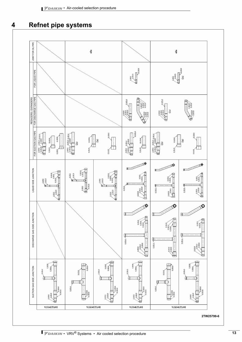
4 Refnet pipe systemsS
UC
TIO
N G
AS
SID
E J
UN
CTI
ON
DIS
CH
AR
GE
GA
S S
IDE
JU
NC
TIO
NLI
QU
ID S
IDE
JU
NC
TIO
NJO
INT
FOR
OIL
PIP
EFO
R S
UC
TIO
N G
AS
PIP
EFO
R D
ISC
HA
RG
E G
AS
PIP
EFO
R L
IQU
ID P
IPE
RE
DU
CE
RS
/ E
XPA
ND
ER
S
2TW25799-6

• Air-cooled selection procedure
• VRV® Systems • Air cooled selection procedure14
3
4 Refnet pipe systems
2TW29119-1
Gas
side
junc
tion
Liqu
idsid
eju
nctio
nFo
rgas
pipe
Forl
iqui
dpi
pe
Redu
cers
I.D.J
25.4
I.D.J
22.2
I.D.J
28.6
I.D.J
31.8
I.D.J
25.4
I.D.J
22.2
I.D.J
28.6
I.D.J
19.1
I.D.J
22.2
I.D.J
25.4
I.D.J
19.1
I.D.J
22.2
I.D.J
19.1
I.D.J
22.2
I.D.J
25.4
I.D.J
28.6
I.D.J
19.1
I.D.J
22.2
I.D.J
25.4
I.D.J
19.1
O.D.J
25.4
I.D.J
12.7
O.D.J
25.4
O.D.J
15.9
I.D.J
22.2
I.D.J
9.5
I.D.J
19.1
I.D.J
25.4
I.D.J
22.2
O.D.J
25.4
I.D.J
34.9
I.D.J
25.4
I.D.J
28.6
I.D.J
19.1
I.D.J
15.9
I.D.J
28.6
I.D.J
31.8
I.D.J
19.1
I.D.J
22.2
I.D.J
19.1
I.D.J
38.1
I.D.J
31.8
I.D.J
25.4
I.D.J
25.4
I.D.J
25.4
I.D.J
19.1
I.D.J
31.8
I.D.J
25.4
I.D.J
19.1
I.D.J
22.2
I.D.J
28.6
I.D.J
31.8
I.D.J
28.6
I.D.J
28.6
I.D.J
28.6
I.D.J
25.4
I.D.J
31.8
I.D.J
28.6
I.D.J
22.2
O.D.J
31.8
O.D.J
31.8
I.D.J
28.6
O.D.J
25.4
I.D.J
28.6
I.D.J
12.7
O.D.J
15.9
I.D.J
9.5
BHFQ23P1357BHFQ23P907
Insu
latio
ntu
be
I.D.J
28.6
I.D.J
25.4
O.D.J
12.7
I.D.J
25.4
I.D.J
15.9
I.D.J
22.2
I.D.J
15.9
I.D.J
19.1I.D
.J15
.9
O.D.J
9.5
I.D.J
25.4
O.D.J
25.4
O.D.J
25.4
I.D.J
19.1
I.D.J
19.1
Disc
harg
ega
ssid
eju
nctio
nFo
rdisc
harg
ega
spi
peFo
rliq
uid
pipe
Join
tfor
pres
sure
equa
lizat
ion
pipe
Forg
aspi
peFo
rpre
ssur
eeq
ualiz
atio
npi
pe
I.D.J
25.4
I.D.J
28.6
I.D.J
15.9
O.D.J
25.4
O.D.J
31.8
I.D.J
25.4
I.D.J
28.6
I.D.J
25.4
I.D.J
22.2
I.D.J
28.6
I.D.J
25.4
I.D.J
22.2
I.D.J
19.1
I.D.J
15.9
I.D.J
19.1
I.D.J
12.7
I.D.J
9.5
I.D.J
19.1
I.D.J
22.2
I.D.J
25.4
I.D.J
28.6
O.D.J
25.4
I.D.J
34.9
I.D.J
41.3
O.D.J
38.1
I.D.J
19.1
I.D.J
22.2
O.D.J
25.4

• VRV® Systems • Air cooled selection procedure 15
• Air-cooled selection procedure
3
4 Refnet pipe systems
1TW29479-1
Liquid side junction Discharge gas side junction Suction gas side junction
I.D.J6I.D.J10
I.D.J12 I.D.J10
I.D.J10 I.D.J6
I.D.J12 I.D.J10
I.D.J10
I.D.J10 I.D.J6
I.D.J6
I.D.J12 I.D.J10
I.D.J12 I.D.J16I.D.J16
I.D.J6I.D.J10I.D.J12
I.D.J12I.D.J16I.D.J20
I.D.J20
I.D.J12I.D.J16
I.D.J16
I.D.J20 I.D.J22
I.D.J10 I.D.J6
I.D.J12 I.D.J10
I.D.J10 I.D.J6
I.D.J10 I.D.J6
I.D.J6I.D.J10
I.D.J12 I.D.J10
I.D.J10I.D.J12
I.D.J6
I.D.J16I.D.J12 I.D.J16
I.D.J12
I.D.J12I.D.J16
I.D.J20 I.D.J22I.D.J20
I.D.J16 I.D.J12
I.D.J6
I.D.J6I.D.J10
I.D.J10
I.D.J12 I.D.J10
I.D.J10
I.D.J20
I.D.J16
I.D.J10I.D.J12
I.D.J16
I.D.J6I.D.J10I.D.J12
I.D.J16I.D.J12
I.D.J16I.D.J12
I.D.J10I.D.J12
I.D.J16
I.D.J20I.D.J12
I.D.J16I.D.J20
I.D.J12
I.D.J10I.D.J12I.D.J16
I.D.J16I.D.J20
I.D.J22I.D.J26I.D.J20
I.D.J16I.D.J20
I.D.J12I.D.J16
I.D.J26
I.D.J20
I.D.J26
I.D.J28I.D.J32
I.D.J12I.D.J16
I.D.J16
I.D.J16
I.D.J20 I.D.J22I.D.J20
I.D.J12
I.D.J10I.D.J12I.D.J16
I.D.J20
I.D.J26 I.D.J22I.D.J20
I.D.J16
I.D.J16I.D.J20
I.D.J26
I.D.J12I.D.J16I.D.J20
I.D.J32
I.D.J26
I.D.J28
I.D.J38 I.D.J32
I.D.J28 I.D.J26
I.D.J16
I.D.J32
I.D.J26 I.D.J20
I.D.J12
I.D.J16
I.D.J16
I.D.J20 I.D.J22I.D.J20
I.D.J12I.D.J16
I.D.J20
I.D.J10I.D.J12I.D.J16
I.D.J26 I.D.J22
I.D.J20
I.D.J16I.D.J20
I.D.J26
I.D.J12I.D.J16I.D.J20
I.D.J32 I.D.J28
I.D.J26
I.D.J28 I.D.J26
I.D.J32
I.D.J16I.D.J20I.D.J26
I.D.J38 I.D.J32
I.D.J16
I.D.J12I.D.J16
I.D.J16
I.D.J16
I.D.J20
O.D.J12I.D.J10
O.D.J20
O.D.J6
O.D.J16
Closed pipes
KHRQ
M58
T7KH
RQM
23M
75T8
KHRQ
M23
M64
T8KH
RQM
23M
29T8
KHRQ
M23
M20
T8KH
RQM
22M
75T8
KHRQ
M22
M64
T8KH
RQM
22M
29T8
KHRQ
M22
M20
T8

• Air-cooled selection procedure
• VRV® Systems • Air cooled selection procedure16
3
4 Refnet pipe systems
1TW29479-1
Liquid side header Discharge gas side header Suction gas side header
I.D.J6 (6x)I.D.J6 (2x)
I.D.J16
I.D.J10 (6x)
I.D.J16
I.D.J10 (6x)
I.D.J16
I.D.J6 (2x)I.D.J6 (6x)
I.D.J16
I.D.J10 (8x)
I.D.J20I.D.J20
I.D.J16
I.D.J6 (6x)I.D.J10 (6x)I.D.J6 (2x)
I.D.J16
I.D.J10 (6x)I.D.J6 (6x)
I.D.J16
I.D.J6 (2x)
I.D.J16
I.D.J20
I.D.J10 (8x)
I.D.J20
I.D.J10 (3x)I.D.J16
I.D.J10 I.D.J12
I.D.J6 (3x)
I.D.J10 (3x)
I.D.J12I.D.J10
I.D.J16
I.D.J10
I.D.J12
I.D.J16I.D.J10 (3x)
I.D.J6 (3x)
I.D.J10I.D.J12
I.D.J6
I.D.J28O.D.J26
O.D.J16
I.D.J6 (3x)
I.D.J10
I.D.J10 (2x)
I.D.J12 (3x)
I.D.J12 (3x)
I.D.J20
I.D.J10 (3x)
I.D.J26I.D.J22
I.D.J16 (3x)
I.D.J12 (3x)
I.D.J10 (3x)
I.D.J12 (3x)I.D.J10 (3x)
I.D.J22
I.D.J10 (3x)
I.D.J16 (3x)I.D.J26
I.D.J20
I.D.J16 (3x)I.D.J12 (3x)
I.D.J16 (3x)I.D.J12 (3x)
I.D.J26
I.D.J10 (2x)
I.D.J20 (3x)
I.D.J28
I.D.J32
I.D.J12 (2x)
I.D.J12
I.D.J26
I.D.J22
I.D.J32
I.D.J20
I.D.J12 (3x)
I.D.J12 (5x)
I.D.J32
I.D.J16
I.D.J20
I.D.J12 (2x)I.D.J16 (2x)
I.D.J16 (3x)I.D.J12 (3x)I.D.J16 (3x)
I.D.J16 (2x)
I.D.J20
I.D.J26
I.D.J22
I.D.J16
I.D.J12
I.D.J28
I.D.J12 (2x)
I.D.J16
I.D.J12
I.D.J20 (6x)I.D.J16 (6x)
I.D.J38
I.D.J12 (2x)
I.D.J20 (3x)
I.D.J20
I.D.J32
I.D.J16 (2x)I.D.J16
I.D.J20
I.D.J20 (3x)
I.D.J26
I.D.J22
I.D.J12 (5x)
I.D.J32
I.D.J28
I.D.J16 (6x)
I.D.J12 (3x)
I.D.J32
I.D.J12 (2x)I.D.J16 (3x)
I.D.J12 (2x)
I.D.J16 (2x)
I.D.J12I.D.J16 (2x)
I.D.J38
I.D.J20 (6x)
I.D.J16 (3x)
I.D.J26
I.D.J10 (3x)
I.D.J20 (2x)
I.D.J16I.D.J20
I.D.J16
I.D.J12 (3x)
I.D.J12
I.D.J16
I.D.J12 (3x)
I.D.J12 (3x)
O.D.J32
O.D.J20 I.D.J22
O.D.J6
I.D.J12
I.D.J10
O.D.J10
I.D.J12
KHRQ
M58
H7KH
RQM
127H
8KH
RQM
250H
8KH
RQM
23M
75H8
KHRQ
M23
M64
H8KH
RQM
23M
29H8
KHRQ
M22
M75
H8KH
RQM
22M
64H8
KHRQ
M22
M29
H8
O.D.J16
I.D.J28O.D.J22
O.D.J12 I.D.J20
I.D.J20O.D.J16
I.D.J28
I.D.J20 I.D.J16 I.D.J12
I.D.J32 I.D.J35 I.D.J42
I.D.J12 I.D.J16
I.D.J26
I.D.J38
I.D.J6I.D.J10O.D.J12
O.D.J26 I.D.J20 I.D.J16 I.D.J12
O.D.J10
Redu
cers
-Exp
ande
rs

• VRV® Systems • Air cooled selection procedure 17
• Air-cooled selection procedure
3
4 Refnet pipe systems
2TW29659-1
Gas
-sid
eju
nctio
nLi
quid
side
junc
tion
Forg
aspi
peFo
rliq
uid
pipe
Redu
cers
I.D.J
22I.D
.J20
I.D.J
32
I.D.J
28I.D
.J26
I.D.J
28
I.D.J
22
I.D.J
16
I.D.J
16
I.D.J
22
I.D.J
20
I.D.J
10I.D
.J12
I.D.J
20
I.D.J
22
I.D.J
26
I.D.J
28
I.D.J
42
O.D.J
32
I.D.J
35
I.D.J
20
O.D.J
19.1
I.D.J
22
O.D.J
32
O.D.J
22.2
I.D.J
28
O.D.J
28.6
I.D.J
16
O.D.J
9.5
I.D.J
10
O.D.J
16
I.D.J
10
I.D.J
12
O.D.J
16
I.D.J
12
O.D.J
22.2
I.D.J
22
I.D.J
20
O.D.J
19.1
O.D.J
12
O.D.J
26
I.D.J
42I.D
.J32
O.D.J
26
I.D.J
28
I.D.J
26
I.D.J
28
I.D.J
20
I.D.J
32
I.D.J
22I.D
.J20
I.D.J
26
I.D.J
38I.D
.J32
I.D.J
26
I.D.J
20
I.D.J
16
I.D.J
16
I.D.J
16I.D
.J20
I.D.J
10I.D
.J12
I.D.J
28I.D
.J32
I.D.J
28I.D
.J28
I.D.J
26
I.D. J
26I.D
.J32
I.D.J
26
I.D.J
28
O.D.J
20
O.D.J
32
O.D.J
32
I.D.J
35
O.D.J
32
I.D.J
42
I.D.J
38
O.D.J
32
I.D.J
28
O.D.J
28.6
I.D.J
16
O.D.J
12
I.D.J
10I.D
.J10
I.D.J
12
I.D.J
20
O.D.J
16
I.D.J
10
O.D.J
9.5
BHFQM22P1517ABHFQM22P1007A
Insu
latio
ntu
beG
asLi
quid
I.D.J
22I.D
.J20
O.D.J
26
I.D.J
16
I.D.J
20
I.D.J
22
I.D.J
26
O.D.J
28
I.D.J
20
I.D.J
22
I.D.J
26
I.D.J
28
O.D.J
26
I.D.J
38
O.D.J
32
I.D.J
22
O.D.J
28
O.D.J
28O.
D.J
38
I.D.J
10
I.D.J
12
O.D.J
12.7
I.D.J
16
O.D.J
15.9
I.D.J
12
O.D.J
16
I.D.J
16
O.D.J
12
I.D.J
16
O.D.J
20
I.D.J
12
O.D.J
12.7
I.D.J
16
O.D.J
15.9

• Air-cooled selection procedure
• VRV® Systems • Air cooled selection procedure18
3
4 Refnet pipe systems
2TW29679-1
Suct
ion
gas
side
junc
tion
Disc
harg
ega
ssid
eju
nctio
nLi
quid
side
junc
tion
Fors
uctio
nga
spi
peFo
rdisc
harg
ega
spi
peFo
rliq
uid
pipe
Parts
foro
ilpi
peRe
duce
rs-E
xpan
ders
I.D.J
25.40
I.D.J
32
I.D.J
28I.D
.J20
I.D.J
22
I.D.J
28I.D
.J26
I.D.J
25.40
I.D.J
22 I.D.J
26I.D
.J28
I.D.J
16
I.D.J
20I.D
.J22
I.D.J
15.90
I.D.J
22I.D
.J20
I.D.J
16I.D
.J10
I.D.J
12
I.D.J
19.10
I.D.J
25.40
I.D.J
28.60
I.D.J
22.20
O.D.J
25.40
I.D.J
35O.
D.J
32
I.D.J
19.10
I.D.J
25.40
O.D.J
25.40
I.D.J
28.60
I.D.J
22.20
I.D.J
10I.D
.J12
O.D.J
15.90
I.D.J
15.90
I.D.J
19.10
I.D.J
22.20
O.D.J
25.40
I.D.J
22.20
I.D.J
19.10
I.D.J
15.90
I.D.J
22I.D
.J20
I.D.J
16
I.D.J
22I.D
.J20
I.D.J
16I.D
.J22
I.D.J
20I.D
.J16
I.D.J
15.90
I.D.J
19.10
I.D.J
22.20
O.D.J
25.40
I.D.J
15.90
I.D.J
20I.D
.J16
I.D.J
22I.D
.J20
I.D.J
22I.D
.J26
I.D.J
28
I.D.J
15.90
I.D.J
32I.D
.J28
I.D.J
25.40
I.D. J
32I.D
.J28
I.D.J
32
I.D.J
38
I.D.J
25.40 I.D
.J25
.40
I.D.J
22 I.D.J
26I.D
.J28
I.D.J
20I.D
.J22
I.D.J
25.40
I.D.J
32
I.D.J
28I.D
.J20
I.D.J
22
I.D.J
28I.D
.J26
I.D.J
20I.D
.J16
I.D.J
10I.D
.J12
O.D.J
32I.D
.J35
I.D.J
42O.
D.J
38
I.D.J
22.20
I.D.J
19.10
I.D.J
22I.D
.J20
I.D.J
10 I.D.J
12
O.D.J
15.90
I.D.J
22I.D
.J20
I.D.J
22I.D
.J20
I.D.J
6
O.D.J
6.35
Redu
cer
Join
t
BHFQM23M1357ABHFQM23M907A

• VRV® Systems • Air cooled selection procedure 19
• Air-cooled selection procedure
3
4 Refnet pipe systems
GA
S S
IDE
JU
NC
TIO
ND
ISC
HA
RG
E G
AS
SID
E J
UN
CTI
ON
LIQ
UID
SID
E J
UN
CTI
ON
FOR
GA
S P
IPE
FOR
DIS
CH
AR
GE
GA
S P
IPE
MM
-INC
H R
ED
UC
ER
SFO
R LI
QUI
D PI
PE
RE
DU
CE
RS
JOIN
T FO
R PR
ESSU
REEQ
UALI
ZATI
ON
PIPE
FOR
GAS
PIP
EFO
R PR
ESSU
REEQ
UALI
ZATI
ON
PIPE
INS
ULA
TIO
N T
UB
E
FOR
LIQ
UID
PIPE
1TW29119-2
• Air-cooled selection procedure
• VRV® Systems • Air cooled selection procedure20
3
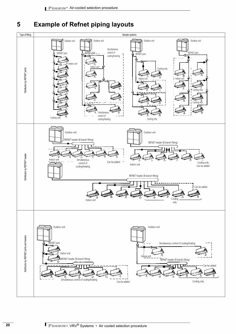
5 Example of Refnet piping layoutsType of fitting Sample systems
Distrib
ution
by R
EFNE
T join
tsDis
tributi
on by
REFN
ET he
ader
Distrib
ution
by RE
FNET
joint
s and
head
ers
Outdoor unit Outdoor unit Outdoor unit Outdoor unit
REFNET joint REFNET joint REFNET jointREFNET joint
Indoor unitIndoor unit
Indoor unit Indoor unit
Cooling only
Cooling only
Cooling only
Cooling only
Cooling only
Simultaneous control of cooling/heating
Simultaneous control of cooling/heating
Outdoor unit Outdoor unit
REFNET header (8 branch fitting)
REFNET header (8 branch fitting)
REFNET header (8 branch fitting)
Indoor unit
Indoor unit
Indoor unit
Can be added
Can be added
Simultaneous control of
cooling/heating
Cooling only
Cooling onlyCan be added
Outdoor unit
REFNET joint
Indoor unit
REFNET header (8 branch fitting)
Simultaneous control of cooling/heatingCan be added
Outdoor unit
Simultaneous control of cooling/heating
Indoor unitREFNET header (8 branch fitting)
Can be added
Cooling only

• VRV® Systems • Air cooled selection procedure 21
• Air-cooled selection procedure
3
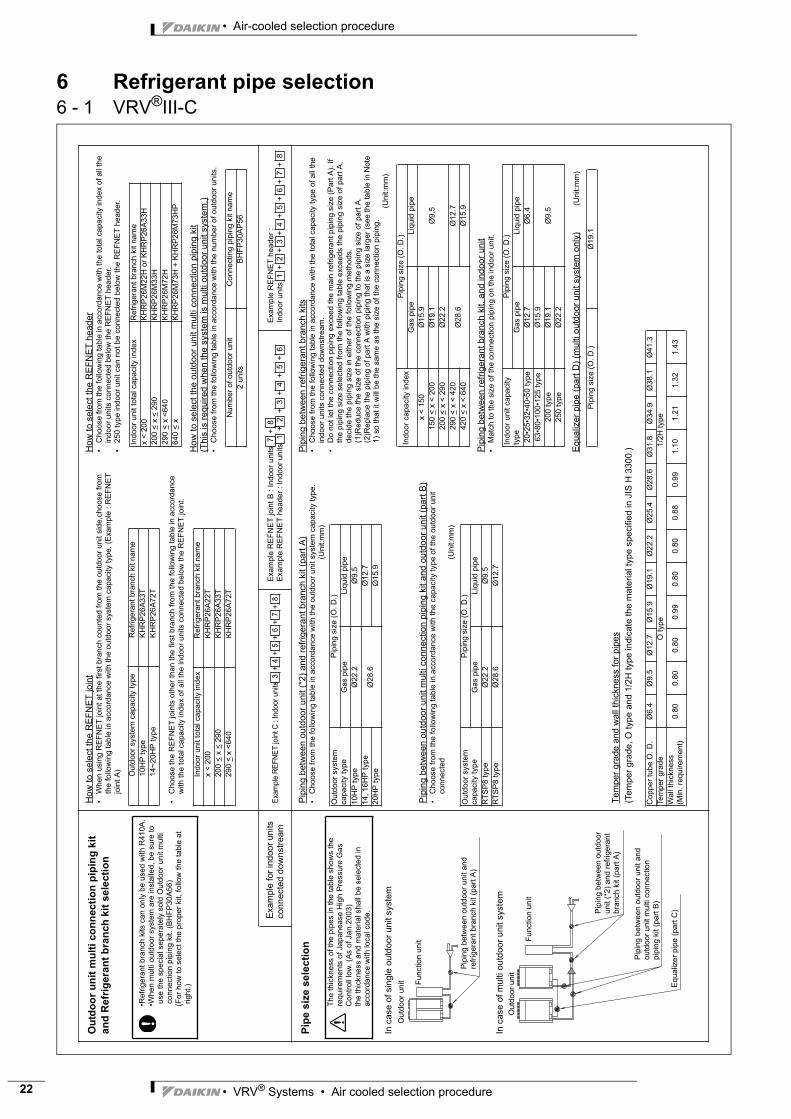
6 Refrigerant pipe selection6 - 1 VRV®III-C
1 ~
8 1
~ 8
1 ~
8
1 ~
8 1
~ 8
1 ~
8
(A, B
)a
bj
k
H2
de
fg
hi
12
34
56
78
c
H4
H1
(A~
G)
H4c
de
fg
h
ij
km
np
q
H2
H1
12
34
56
7
8
H3
ra
bs
H4
a
b
H4
H1
12
34
56
78
H2
dc
ef
gh
ij
ra
s
b
H3
AB
CD
EF
G
(A~
G)
ab
cd
ef
gh
ij
km
np
q
H2
H1
12
34
56
7
8
H4
AB
CD
EF
G
AB
H2
78
(A, B
)
k
de
fg
hi
12
34
56
c
H4
H1
j
H3
ra
b
sA
B
H1
12
34
56
78
H2
dc
ef
gh
ij
sr
a
RE
FN
ET
he
ad
er
RE
FN
ET
he
ad
er
Fu
nctio
n u
nit
Fu
nction
un
it
: In
do
or
un
it
: O
utd
oo
r u
nit
: O
utd
oo
r u
nit
Bra
nc
h w
ith
RE
FN
ET
hea
de
rB
ran
ch
wit
h R
EF
NE
T jo
int
an
d h
ead
er
: O
utd
oo
r un
itF
un
ction
un
it
: In
do
or
un
it
RE
FN
ET
jo
int
RE
FN
ET
h
ea
der
Ou
tdo
or
un
itF
unctio
n u
nit
RE
FN
ET
join
t
RE
FN
ET
he
ad
er
: In
do
or
un
it
Outd
oo
r u
nit
Fun
ction
un
it
RE
FN
ET
join
t
: In
do
or
unit
: In
do
or
unit
RE
FN
ET
join
t
Outd
oo
r u
nit
Fun
ctio
n u
nit
Bra
nch
wit
h R
EF
NE
T jo
int
Sin
gle
o
utd
oo
rs
ys
tem
Mu
lti
ou
tdo
or
sys
tem
Ma
xim
um
all
ow
ab
le
len
gth
All
ow
ab
le
he
igh
td
iffe
ren
ce
Betw
ee
n o
utd
oo
r un
it (
*2)
and
ind
oor
unit
Betw
een o
utd
oor
unit
and funct
ion u
nit
Betw
een o
utd
oor
unit
and o
utd
oor
unit
Multi
connect
ion p
ipin
g k
it
Betw
een o
utd
oor
and in
door
units
Betw
een in
door
and in
door
units
Betw
een o
utd
oor
and o
utd
oor
units
Betw
een o
utd
oor
unit
and funct
ion u
nit
Allo
wa
ble
len
gth
aft
er
the
bra
nc
h
Actu
al pip
e
len
gth
Eq
uiv
ale
nt
len
gth
Tota
l ext
entio
n le
ngth
Diff
eren
ce in
hei
ght
Diff
eren
ce in
hei
ght
Diff
eren
ce in
hei
ght
Diff
eren
ce in
hei
ght
Actu
al an
d
equ
iva
lent
len
gth
Pip
e len
gth
be
twee
n o
utd
oo
r un
it (
*2)
an
d in
do
or
un
it <
165
m
Diffe
ren
ce
in
he
igh
t b
etw
ee
n o
utd
oo
r un
it a
nd in
do
or
un
it (
H1
) <
50m
(M
ax 4
0m
if th
e o
utd
oo
r un
it is b
elo
w)
Diffe
ren
ce
in
he
igh
t b
etw
ee
n in
do
or
un
its (
H2)
<1
5m
Diffe
ren
ce
in
he
igh
t b
etw
ee
n o
utd
oo
r un
its(H
3)
<5m
Diffe
rence
in h
eig
ht b
etw
een
ou
tdo
or
un
it a
nd f
un
ction
un
it (
H4
) <
1m
Act
ual p
ipe le
ngth
fro
m first
refr
igera
nt bra
nch
kit
(eith
er
RE
FN
ET
join
t or
RE
FN
ET
header)
to in
door
unit
< 4
0m
(N
ote
2)
Exa
mp
le 8
:
c +
d +
e +
f +
g +
h +
q <
Exa
mple
6
: c +
i <
40m
, 8
: j +
<
40m
Actu
al pip
e len
gth
fro
m o
utd
oo
r u
nit t
o f
un
ctio
n u
nit,
tha
t fr
om
first
ou
tdo
or
unit m
ulti co
nn
ectio
n p
ipin
g k
it to
ou
tdo
or
unit
< 1
0m
Eq
uiv
ale
nt
pip
e len
gth
fro
m o
utd
oor
unit t
o f
unctio
n u
nit,
tha
t fr
om
first
ou
tdo
or
un
it m
ulti co
nn
ectio
n p
ipin
g k
it to
ou
tdo
or
unit <
13
m
Exa
mple
8
: j
<4
0m
Exa
mp
le
8
: a +
b +
c +
d +
e +
f +
g +
h +
q <
165
mE
xam
ple
6
: a
+ b
+ c
+ i <
16
5m
,
Tota
l pip
ing le
ng
th f
rom
ou
tdo
or
un
it (
*2)
to a
ll in
do
or
un
it <
500
m
: O
utd
oor
un
it
Fu
nctio
n u
nit
(*1
) “
”
Ind
ica
te t
he
Ou
tdoo
r u
nit m
ulti
co
nn
ectio
n p
ipin
g k
it.
(*2
) In
ca
se o
f m
ulti ou
tdo
or
syste
m, re
-rea
d “
outd
oor
un
it”
to “
Outd
oor
un
it m
ulti co
nn
ectio
n
pip
ing
kit”
as s
ee
n fro
m t
he
in
do
or
unit.
Eq
uvale
nt p
ipe
le
ng
th b
etw
ee
n o
utd
oo
r un
it (
*2)
an
d in
do
or
un
it <
190
m (
No
te 1
)
(Assum
e e
qiv
ale
nt
pip
e len
gth
of
RE
FN
ET
jo
int to
be
0.5
m, th
at
of
RE
FN
ET
hea
der
to b
e 1
m,
tha
t o
f fu
nctio
n u
nit t
o b
e 6
m f
or
ca
lcula
tio
n p
urp
oses)
a <
10m
(Eq
uiv
ale
nt
leng
th <
13
m)
r < 1
0m
(Eq
uiv
ale
nt
leng
th <
13
m)
s <
10
m(E
quiv
ale
nt
leng
th <
13
m)
Exa
mple
8
: a
+ b
+ j <
165
m8
: a
+ b
+ j +
<
165
m
Actu
al P
ipe
L
eng
th
• Air-cooled selection procedure
• VRV® Systems • Air cooled selection procedure22
3
6 Refrigerant pipe selection6 - 1 VRV®III-C
Ou
tdo
or
un
it m
ult
i co
nn
ecti
on
pip
ing
kit
an
d R
efr
igera
nt
bra
nch
kit
sele
cti
on
Ho
w t
o s
ele
ct
the
RE
FN
ET
join
t•
Wh
en
usin
g R
EF
NE
T jo
int
at th
e f
irst
bra
nch c
oun
ted
fro
m t
he
ou
tdo
or
unit s
ide,c
hoo
se f
rom
th
e fo
llow
ing tab
le in
acco
rdan
ce w
ith
th
e o
utd
oo
r syste
m c
apacity t
ype
. (E
xa
mp
le : R
EF
NE
T
join
t A
)
•C
hoo
se t
he
RE
FN
ET
join
ts o
the
r th
an t
he
fir
st b
ranch
fro
m th
e f
ollo
win
g ta
ble
in
accord
ance
w
ith
th
e t
ota
l ca
pa
city ind
ex o
f a
ll th
e ind
oor
units c
on
ne
cte
d b
elo
w th
e R
EF
NE
T jo
int.
Ho
w t
o s
ele
ct
the
RE
FN
ET
he
ad
er
•C
ho
ose
fro
m the
fo
llow
ing ta
ble
in
acco
rdan
ce w
ith
th
e tota
l ca
pacity in
de
x o
f all
the
ind
oo
r un
its c
onn
ecte
d b
elo
w t
he
RE
FN
ET
hea
der.
•2
50
typ
e ind
oo
r u
nit c
an
no
t b
e c
on
ne
cte
d b
elo
w t
he R
EF
NE
T h
ead
er.
Ho
w t
o s
ele
ct
the
outd
oor
un
it m
ulti co
nn
ectio
n p
ipin
g k
it(T
his
is r
eq
uir
ed
whe
n t
he
syste
m is m
ulti ou
tdoo
r u
nit s
yste
m.)
•C
ho
ose
fro
m t
he
follo
win
g tab
le in a
ccord
ance
with t
he
nu
mb
er
of o
utd
oo
r un
its.
•Re
frig
era
nt b
ranch
kits c
an o
nly
be u
se
d w
ith R
410
A.
•Whe
n m
ulti ou
tdo
or
syste
m a
re insta
lled
, b
e s
ure
to
u
se t
he s
pe
cia
l sep
era
tely
sold
Ou
tdo
or
unit m
ulti
co
nn
ectio
n p
ipin
g k
it. (B
HF
P3
0A
56)
(For
how
to
se
lect th
e p
rop
er
kit, fo
llow
th
e tab
le a
t ri
gh
t.)
Exa
mp
le for
indo
or
un
its
con
ne
cte
d d
ow
nstr
eam
Exa
mple
RE
FN
ET
join
t C
: Indoor
units
3 +
4 +
5 +
6 +
7 +
8
Exa
mp
le R
EF
NE
T join
t B
: I
nd
oo
r u
nits 7
+
8
Exa
mp
le R
EF
NE
T h
ead
er
: In
do
or
units
1
+
2
+
3
+
4
+
5
+
6E
xa
mp
le R
EF
NE
T h
ea
de
r :
Ind
oo
r u
nits 1 +
2
+
3
+
4
+
5 +
6
+
7
+
8
Pip
e s
ize
se
lec
tio
nP
ipin
g b
etw
een
ou
tdoo
r u
nit (
*2)
an
d r
efr
ige
ran
t b
ranch k
it (
part
A)
•C
hoo
se f
rom
the
fo
llow
ing ta
ble
in
acco
rdan
ce w
ith
th
e o
utd
oo
r un
it s
yste
m c
apacity t
ype
.(U
nit:m
m)
Pip
ing b
etw
een
ou
tdoo
r u
nit m
ulti co
nn
ectio
n p
ipin
g k
it a
nd
ou
tdo
or
unit (
pa
rt B
)•
Ch
oo
se f
rom
the
fo
llow
ing ta
ble
in
acco
rdan
ce w
ith
th
e c
apa
city typ
e o
f th
e o
utd
oor
unit
con
necte
d(U
nit:m
m)
Pip
ing
be
twe
en r
efr
ige
rant
bra
nch
kits
•C
ho
ose
fro
m t
he
follo
win
g tab
le in a
ccord
ance
with t
he
to
tal ca
pacity t
ype
of
all
the
ind
oo
r un
its c
onn
ecte
d d
ow
nstr
eam
.•
Do
no
t le
t th
e c
on
ne
ction
pip
ing e
xcee
d t
he
ma
in r
efr
igera
nt p
ipin
g s
ize
(P
art
A).
If
the p
ipin
g s
ize s
ele
cte
d f
rom
th
e f
ollo
win
g ta
ble
exce
eds t
he
pip
ing s
ize
of
part
A,
decid
e th
e p
ipin
g s
ize in
eith
er
of
the
fo
llow
ing m
eth
ods.
(1)R
ed
uce
th
e s
ize
of
the
con
ne
ction
pip
ing t
o th
e p
ipin
g s
ize o
f pa
rt A
.(2
)Rep
lace
th
e p
ipin
g o
f pa
rt A
with
pip
ing
tha
t is
a s
ize
larg
er
(se
e the
ta
ble
in N
ote
1
) so t
hat
it w
ill b
e t
he
sam
e a
s the
siz
e o
f th
e c
onn
ectio
n p
ipin
g.
(Unit:m
m)
Pip
ing
be
twe
en r
efr
ige
rant
bra
nch
kit,
and
in
do
or
un
it•
Ma
tch t
o th
e s
ize
of
the
co
nne
ction
pip
ing o
n t
he
ind
oor
unit.
Eq
ua
lize
r p
ipe
(pa
rt D
) (m
ulti o
utd
oo
r u
nit s
yste
m o
nly
)(U
nit:m
m)
Th
e t
hic
kne
ss o
f th
e p
ipes in
th
e tab
le s
ho
ws th
e
req
uir
em
en
ts o
f Japan
ea
se H
igh
Pre
ssu
re G
as
Co
ntr
oll
low
. (A
s o
f Ja
n.2
00
3)
the t
hic
kn
ess a
nd
ma
teri
al sh
all
be s
ele
cte
d in
a
ccord
ance
with lo
cal co
de.
In c
ase o
f sin
gle
outd
oo
r un
it s
yste
m
In c
ase o
f m
ulti ou
tdoo
r u
nit s
yste
m
Te
mpe
r g
rade
an
d w
all
thic
kne
ss f
or
pip
es
(Te
mpe
r g
rade
, O
typ
e a
nd
1/2
H t
yp
e in
dic
ate
th
e m
ate
rial ty
pe
sp
ecifie
d in
JIS
H 3
30
0.)
Ou
tdoo
r syste
m c
apacity t
ype
Re
frig
era
nt b
ranch
kit n
am
e
10H
P t
ype
KH
RP
26
A3
3T
14~
20
HP
typ
eK
HR
P26
A7
2T
Ind
oo
r u
nit t
ota
l ca
pa
city in
dex
Refr
ige
rant
bra
nch k
it n
am
e
x <
20
0K
HR
P2
6A
22T
20
0 <
x <
29
0K
HR
P2
6A
33T
29
0 <
x <
64
0K
HR
P2
6A
72T
Ind
oo
r u
nit t
ota
l ca
pa
city in
dex
Refr
ige
ran
t bra
nch
kit n
am
e
x <
20
0K
HR
P2
6M
22
H o
r K
HR
P26
A33
H
200
< x
< 2
90
KH
RP
26M
33
H
290
< x
<64
0K
HR
P2
6M
72
H
640
< x
KH
RP
26M
73
H +
KH
RP
26M
73
HP
Num
be
r of
outd
oor
un
itC
onn
ectin
g p
ipin
g k
it n
am
e
2 u
nits
BH
FP
30A
P56
Ou
tdoo
r syste
m
capa
city typ
e
Pip
ing s
ize
(O
. D
.)
Ga
s p
ipe
Liq
uid
pip
e
10
HP
typ
eØ
22.2
Ø9
.5
14
, 1
6H
P t
ype
Ø2
8.6
Ø1
2.7
20
HP
typ
eØ
15.9
Ou
tdoo
r syste
m
capa
city typ
e
Pip
ing s
ize
(O
. D
.)
Ga
s p
ipe
Liq
uid
pip
e
RT
SP
8 typ
eØ
22.2
Ø9
.5
RT
SP
8 typ
eØ
28.6
Ø1
2.7
Ind
oo
r ca
pacity in
de
xP
ipin
g s
ize (
O.
D.)
Gas p
ipe
Liq
uid
pip
e
x <
150
Ø1
5.9
Ø9
.5 1
50
< x
< 2
00
Ø1
9.1
200
< x
< 2
90
Ø2
2.2
290
< x
< 4
20
Ø2
8.6
Ø12
.7
420
< x
< 6
40
Ø15
.9
Ind
oo
r u
nit c
apacity
type
Pip
ing
siz
e (
O.
D.)
Gas p
ipe
Liq
uid
pip
e
20
•25
•32
•40
•50 t
ype
Ø1
2.7
Ø6
.4
63•8
0•1
00
•125
typ
eØ
15
.9
Ø9
.52
00
typ
eØ
19
.1
250
typ
eØ
22
.2
Pip
ing s
ize
(O
. D
.)Ø
19
.1
Fu
nctio
n u
nit
Pip
ing b
etw
ee
n o
utd
oor
unit a
nd
re
frig
era
nt
bra
nch
kit (
part
A)
Outd
oor
un
it
Outd
oo
r un
it
Fu
nctio
n u
nit
Pip
ing b
etw
ee
n o
utd
oor
un
it (
*2)
and
refr
ige
rant
bra
nch
kit (
pa
rt A
)
Pip
ing
be
twe
en o
utd
oor
unit a
nd
ou
tdo
or
unit m
ulti con
nectio
n
pip
ing
kit (
pa
rt B
)
Eq
ua
lize
r pip
e (
pa
rt C
)
Cop
pe
r tu
be
O.
D.
Ø6.4
Ø9
.5Ø
12
.7Ø
15
.9Ø
19.1
Ø2
2.2
Ø2
5.4
Ø28
.6Ø
31.8
Ø3
4.9
Ø3
8.1
Ø41
.3
Tem
pe
r gra
de
O t
ype
1/2
H t
ype
Wa
ll th
ickn
ess
(Min
. re
quir
em
en
t)0
.80
0.8
00.8
00.9
90
.80
0.8
00.8
80.9
91
.10
1.2
11.3
21.4
3

• VRV® Systems • Air cooled selection procedure 23
• Air-cooled selection procedure
3
6 Refrigerant pipe selection6 - 1 VRV®III-C
8
c+
d+
e+
f+g
+h
+q
≤ 9
0 m
a+
b+
c×
2+
d×
2+
e×
2+
f×2
+g
×2
+h
×2
+i+
j+k
+ +
m+
n+
p+
q≤
500
m
i, j..
.....
p, q
≤ 4
0 m
(a+
b+
c+
d+
e+
f+g
+h
+q
)-(a
+b
+i)
≤ 40
m
φ 9.
5 →
φ12
.7φ1
2.7
→ φ
15.9
φ15.
9 →
φ19
.1φ1
9.1
→ φ
22.2
φ22.
2 →
φ25
.4*
φ28.
6 →
φ31
.8*
φ34.
9 →
φ38
.1*
a
b
ij
km
np
cd
ef
hq
gA
BC
DE
FG
12
34
56
78
(A~
G)
R =
φ22.
2 φ 15.
9
φ9.5
φ19.
1 φ12.
7
φ6.4
0.37 0.
18
0.05
9
0.26 0.
12
0.02
2
R =
40
× 0
.18
+ 2
5 ×
0.1
2 +
50
× 0
.059
+ 8
0 ×
0.0
22 =
14.
91
a : φ
15.9
× 1
0mb
: φ15
.9 ×
30m
c : φ
12.7
× 2
0md
: φ6.
4 ×
10m
e : φ
6.4
× 1
0mf
: φ6.
4 ×
20m
g : φ
6.4
× 2
0mh
: φ6.
4 ×
10m
i : φ
6.4
× 1
0mj
: φ9.
5 ×
20m
k : φ
9.5
× 1
0m:φ
9.5
× 1
0m
r : φ
12.7
× 5
ms
: φ9.
5 ×
10m
a, b
c, r
j, k,
, s
d~i
14.9
kg
RTS
YQ10
PY1
RTS
YQ14
PY1
RTS
YQ16
PY1
RTS
YQ20
PY1
—
1.3k
g
2.3k
g
—
φ9.5
→ φ
12.7
φ12.
7 →
φ15
.9
φ15.
9 →
φ19
.1
φ22.
2 →
φ25
.4 (
*)
φ28.
6 →
φ31
.8 (
*)
Ma
in p
ipes
Ro
un
d o
ff in
un
its o
f 0.1
k g
: O
utd
oo
r un
it
Re
qu
ire
d C
ond
itio
ns
Exam
ple
for
refr
igera
nt b
ranch
usin
g R
EF
NE
T jo
int a
nd
RE
FN
ET
hea
der
for
the
syste
ms a
nd e
ach
pip
e le
ngth
as s
ho
wn b
elo
w.
Syste
m:
RT
SY
Q2
0P
Y1
Inde
pe
nd
ant
ou
tdo
or
un
it: R
TS
Q8P
Y1,
RT
SQ
12
PY
1
Fu
nctio
n u
nit:
BT
SQ
20P
Y1
Ou
tdo
or
un
it Fu
nctio
n u
nit
Incle
ase
ga
s a
nd
liq
uid
pip
e
siz
e b
oth
.
: In
ca
se o
f sin
gle
outd
oo
r un
it s
yste
m
Syste
m
RT
SY
Q1
0 t
ype
RT
SY
Q1
4 t
ype
RT
SY
Q1
6 t
ype
RT
SY
Q2
0 t
ype
1. It
is n
ecessa
ry to
in
cre
ase
th
e p
ipe
siz
e b
etw
een
the
first b
ranch
kit a
nd t
he
fin
al
bra
nch
kit. (R
edu
cers
must be
pro
cu
red o
n s
ite
) H
ow
eve
r, the
pip
es th
at are
sa
me
p
ipe s
ize
with m
ain
pip
e m
ust
no
t b
e in
cre
ase
d.
Tota
l len
gth
(m)
of li
quid
pip
ing
size
at
Ho
w t
o c
alc
ula
te t
he
ad
dit
ion
al
refr
ige
ran
t to
be
ch
arg
ed
Ad
ditio
nal re
frig
era
nt to
be
ch
arg
ed
: R
(kg
)R
sh
ould
be
rou
nde
d o
ff in
u
nits o
f 0
.1 k
g.
Tota
l len
gth
(m)
of li
quid
pip
ing
size
at
Tota
l len
gth
(m)
of li
quid
pip
ing
size
at
Tota
l len
gth
(m)
of li
quid
pip
ing
size
at
Tota
l len
gth
(m)
of li
quid
pip
ing
size
at
Tota
l len
gth
(m)
of li
quid
pip
ing
size
at
SY
ST
EM
NA
ME
THE
AMO
UN
T O
F R
EFR
IGER
ANT
Gas
Not
incre
ased
Liq
uid
No
te 1
.
Wh
en
th
e e
qu
iva
len
t le
ngth
be
twee
n o
utd
oo
r (*
2)
an
d
ind
oo
r u
nits is 9
0m
or
mo
re,
the
siz
e o
f m
ain
pip
es (
figu
re
on
rig
ht)
mu
st b
e in
cre
ase
d a
ccord
ing
to
th
e r
igh
t ta
ble
. In
doo
r un
it
: In
ca
se
of m
ulti o
utd
oo
r u
nit s
yste
m
Incle
ase
ga
s a
nd liq
uid
pip
e
siz
e b
oth
.
First
refr
igera
nt
bra
nch k
itF
irst
refr
igera
nt
bra
nch k
it
Indo
or
un
it
Main
pip
es
Note
2.
Allo
wa
ble
le
ng
th a
fte
r th
e fir
st re
frig
era
nt
bra
nch k
it t
o in
do
or
un
its is 4
0m
or
less, h
ow
eve
r it c
an
be
exte
nde
d u
p t
o 9
0m
if a
ll th
e f
ollo
win
g c
on
ditio
ns a
re s
atisfied
.
Exa
mp
le D
raw
ing
s (
In c
ase
of
“Bra
nc
h w
ith
RE
FN
ET
jo
int”
)
2. F
or
calc
ula
tion
of T
ota
l e
xte
nsio
n le
ngth
, th
e a
ctu
al le
ngth
of ab
ove
pip
es m
ust b
e
do
ub
led.
(exce
pt m
ain
pip
e a
nd
the
pip
es a
re n
ot
incre
ase
d).
3. In
do
or
un
it to
th
e n
eare
st b
ranch
kit <
40
m
4. T
he d
iffe
rence
be
twee
n
[Outd
oo
r un
it to
th
e fa
rthe
st
ind
oo
r u
nit]
an
d [
Outd
oo
r u
nit t
o t
he
ne
are
st
indo
or
un
it]
< 4
0m
*If
ava
ilable
on t
he
site ,
use
th
is s
ize.
Oth
erw
ise
it ca
n n
ot
be in
cre
ase
d.
: O
utd
oor
unit
Incre
ase t
he
pip
e s
ize o
f c,
d,
e ,
f ,g
, h
The
fa
rth
est
ind
oor
unit
8
The
ne
are
st
indo
or
un
it 1
: F
unctio
n u
nit
:RE
FN
ET
join
t
Ind
oo
r un
it (
1
-
8
)
: In
cre
ase
the
pip
e s
ize
as f
ollo
ws.
*If
ava
ilable
on
the
site
, u
se
th
is s
ize.
Oth
erw
ise,
it c
an
no
t b
e in
cre
ase
d.
FO
R T
HE
SY
ST
EM

• Air-cooled selection procedure
• VRV® Systems • Air cooled selection procedure24
3
6 Refrigerant pipe selection6 - 2 Piping thickness
O : annealed
1/2H : half-hard
For half hard pipes the maximum allowed tensile stress is 61 N/mm2. For this reason the 0.2% proof strength of the half hard pipe shall be minimum 61 N/mm2.
The bending radius is more than or equal to 3 times the diameter of the pipe.
Piping diameter Material Minimum thickness [mm]Ø 6.4 O 0.8Ø 9.5 O 0.8
Ø 12.7 O 0.8Ø 15.9 O 0.99Ø 19.1 1/2H 0.8Ø 22.2 1/2H 0.8Ø 25.4 1/2H 0.88Ø 28.6 1/2H 0.99Ø 31.8 1/2H 1.10Ø 34.9 1/2H 1.21Ø 38.1 1/2H 1.32Ø 41.3 1/2H 1.43

ÉEEDEN09-203^ËÍ
Daikin Europe N.V. is approved by LRQA for its QualityManagement System in accordance with the ISO9001standard. ISO9001 pertains to quality assurance regardingdesign, development, manufacturing as well as to servicesrelated to the product.
Daikin units comply with the European regulations thatguarantee the safety of the product.
EEDE
N09-
203 •
05/20
09 •
Copy
right
Daiki
nTh
e pre
sent
publi
catio
n sup
erse
des E
EDEN
08-2
03Pr
epar
ed in
Belg
ium by
Lann
oo (
www.
lanno
oprin
t.be)
, a co
mpan
y who
se co
ncer
n for
the en
viron
mont
is se
t in th
e EMA
S an
d ISO
1400
1 sys
tems.
Resp
onsib
le Ed
itor:
Daiki
n Eur
ope N
.V., Z
andv
oord
estra
at 30
0, B-
8400
Oos
tende
The present publication is drawn up by way of information only and does notconstitute an offer binding upon Daikin Europe N.V.. Daikin Europe N.V. hascompiled the content of this publication to the best of its knowledge. Noexpress or implied warranty is given for the completeness, accuracy,reliability or fitness for particular purpose of its content and the products andservices presented therein. Specifications are subject to change withoutprior notice. Daikin Europe N.V. explicitly rejects any liability for any direct orindirect damage, in the broadest sense, arising from or related to the useand/or interpretation of this publication. All content is copyrighted by DaikinEurope N.V..
VRV® products are not within the scope of the Euroventcertification programme.
Naamloze VennootschapZandvoordestraat 300B-8400 Oostende, Belgiumwww.daikin.euBE 0412 120 336RPR Oostende
Daikin’s unique position as a manufacturer of airconditioning equipment, compressors andrefrigerants has led to its close involvement inenvironmental issues. For several years Daikin hashad the intension to become a leader in the provisionof products that have limited impact on theenvironment. This challenge demands the eco designand development of a wide range of products and anenergy management system, resulting in energyconservation and a reduction of waste.
ISO14001 assures an effective environmentalmanagement system in order to help protect human healthand the environment from the potential impact of ouractivities, products and services and to assist inmaintaining and improving the quality of the environment.


![Green building solutions - daikin.mcquay.hudaikin.mcquay.hu/1_VRV/Documents/3_[Angol]_Katalógusok/Green Building Solutions...8 2. Top seasonal efficiency Both BREEAM and LEED green](https://static.fdocuments.net/doc/165x107/5e47b4df3e7d770b22519bc9/green-building-solutions-angolkatalgusokgreen-building-solutions-8-2.jpg)

![Hotel solutions - daikin.mcquay.hudaikin.mcquay.hu/1_VRV/Documents/3_[Angol]_Katalógusok/VRV Hotel megoldás ismertető...2 + Heat is recovered from refrigerated display cases and](https://static.fdocuments.net/doc/165x107/5e47b4e03e7d770b22519bca/hotel-solutions-angolkatalgusokvrv-hotel-megolds-ismertet-2-heat.jpg)
