SYSMAC CQM1H/CQM1 Series Dedicated I/O Units - OMRON · PDF fileSYSMAC CQM1H/CQM1 Series...
315
OPERATION MANUAL Cat. No. W238-E1-10 SYSMAC CQM1H/CQM1 Series Dedicated I/O Units
-
Upload
truongthien -
Category
Documents
-
view
229 -
download
3
Transcript of SYSMAC CQM1H/CQM1 Series Dedicated I/O Units - OMRON · PDF fileSYSMAC CQM1H/CQM1 Series...

Cat. No. W238-E1-10
OPERATION MANUAL
SYSMACCQM1H/CQM1 SeriesDedicated I/O Units

CQM1H/CQM1SeriesDedicated I/O UnitsOperation ManualRevised November 2003

iv

6495
Notice of Changes to Information on
Conformance to EC Directives OMRON Corporation
Applicable Manual W238-E1-10
Thank you for supporting OMRON products. The EC Directive EN 61131-2 was modified as of May 1, 2006. As a result of the modification, the EC Directive information provided in the manual is not completely accurate. Please use the information provided below.
Conformance to EC Directives Applicable Directives
• EMC Directives • Low Voltage Directive
Concepts EMC Directives
OMRON supplies electric devices that are used built into other devices or manufacturing equipment. These OMRON products are designed to conform to the related EMC standards (see note) so that the devices or equipment in which they are used can more easily conform to EMC standards. EMC-related performance of the OMRON devices that conform to EC Directives will vary depending on the configuration, wiring, and other conditions of the equipment or control panel on which the OMRON devices are installed. The customer must, therefore, perform the final check to confirm that devices and the overall machine conform to EMC standards.
Note: Applicable EMC (Electromagnetic Compatibility) standards are as follows: EN 61131-2
Low Voltage Directive Always ensure that devices operating at voltages of 50 to 1,000 V AC and 75 to 1,500 V DC meet the required safety standards for the PLC (EN 61131-2).
Conformance to EC Directives CQM1-series products conform to EC Directives (see note). However, the following precautions must be observed to ensure that the machine or device in which the CQM1 PLC is used conforms to EC Directives:
1 The CQM1 PLC must be installed within a control panel. 2 You must use reinforced insulation or double insulation for the DC power supplies connected to the
power supply terminals on PLCs that take DC power and for the DC power supplies connected to I/O Units. The DC power supply connected to the power supply terminals on PLCs using DC power must have an output hold time of at least 10 ms.
3 CQM1-series products conforming to EC Directives also conform to EN 61131-2 for EMI. Radiated emission characteristics (10-m regulations) may vary depending on the configuration of the control panel used, other devices connected to the control panel, wiring, and other conditions. You must therefore confirm that the overall machine or equipment conforms to EC Directives even when using CQM1-series products that conform to EC Directives.
Note: Of the products that appear in this manual, the following products conform to EC Directives. CQM1-LK501 I/O Link Unit CQM1-AD041 Analog Input Unit CQM1-DA021 Analog Output Unit CQM1-IPS0 Analog Power Supply Units CQM1-TC20/TC30 Temperature Control Units
Conditions for Conforming to EMC Directives The following immunity test conditions (i.e., error resulting from momentary variations in I/O data) apply to CQM1 Analog I/O Units.
Overall Accuracy CQM1-AD041 Analog Input Unit: +12%/−6% CQM1-DA021 Analog Output Unit: +12%/−6%

Notice:OMRON products are manufactured for use according to proper procedures by a qualified operatorand only for the purposes described in this manual.
The following conventions are used to indicate and classify precautions in this manual. Always heedthe information provided with them. Failure to heed precautions can result in injury to people or dam-age to property.
!DANGER Indicates an imminently hazardous situation which, if not avoided, will result in death orserious injury.
!WARNING Indicates a potentially hazardous situation which, if not avoided, could result in death orserious injury.
!Caution Indicates a potentially hazardous situation which, if not avoided, may result in minor ormoderate injury, or property damage.
OMRON Product ReferencesAll OMRON products are capitalized in this manual. The word “Unit” is also capitalized when it refers toan OMRON product, regardless of whether or not it appears in the proper name of the product.
The abbreviation “Ch,” which appears in some displays and on some OMRON products, often means“word” and is abbreviated “Wd” in documentation in this sense.
The abbreviation “PC" means Programmable Controller and is not used as an abbreviation for anythingelse.
Visual AidsThe following headings appear in the left column of the manual to help you locate different types ofinformation.
Note Indicates information of particular interest for efficient and convenient opera-tion of the product.
1,2,3... 1. Indicates lists of one sort or another, such as procedures, checklists, etc.
OMRON, 1993All rights reserved. No part of this publication may be reproduced, stored in a retrieval system, or transmitted, in any form, orby any means, mechanical, electronic, photocopying, recording, or otherwise, without the prior written permission ofOMRON.
No patent liability is assumed with respect to the use of the information contained herein. Moreover, because OMRON is con-stantly striving to improve its high-quality products, the information contained in this manual is subject to change withoutnotice. Every precaution has been taken in the preparation of this manual. Nevertheless, OMRON assumes no responsibilityfor errors or omissions. Neither is any liability assumed for damages resulting from the use of the information contained inthis publication.
v

vi

TABLE OF CONTENTS
PRECAUTIONS . . . . . . . . . . . . . . . . . . . . . . . . . . . . . . . . xv1 Intended Audience . . . . . . . . . . . . . . . . . . . . . . . . . . . . . . . . . . . . . . . . . . . . . . . . . xvi2 General Precautions . . . . . . . . . . . . . . . . . . . . . . . . . . . . . . . . . . . . . . . . . . . . . . . . xvi3 Safety Precautions. . . . . . . . . . . . . . . . . . . . . . . . . . . . . . . . . . . . . . . . . . . . . . . . . . xvi4 Operating Environment Precautions . . . . . . . . . . . . . . . . . . . . . . . . . . . . . . . . . . . . xvii5 Application Precautions . . . . . . . . . . . . . . . . . . . . . . . . . . . . . . . . . . . . . . . . . . . . . xviii
PART IB7A Interface Unit . . . . . . . . . . . . . . . . . . . . . . . . . . . . . . 1SECTION 1Features and System Configuration . . . . . . . . . . . . . . . . 3
1-1 Features . . . . . . . . . . . . . . . . . . . . . . . . . . . . . . . . . . . . . . . . . . . . . . . . . . . . . . . . . . 41-2 System Configuration . . . . . . . . . . . . . . . . . . . . . . . . . . . . . . . . . . . . . . . . . . . . . . . 51-3 Connecting Devices . . . . . . . . . . . . . . . . . . . . . . . . . . . . . . . . . . . . . . . . . . . . . . . . 51-4 Word Allocation . . . . . . . . . . . . . . . . . . . . . . . . . . . . . . . . . . . . . . . . . . . . . . . . . . . 61-5 Bit Allocation . . . . . . . . . . . . . . . . . . . . . . . . . . . . . . . . . . . . . . . . . . . . . . . . . . . . . 7
SECTION 2Nomenclature and Settings . . . . . . . . . . . . . . . . . . . . . . . 11
2-1 Nomenclature . . . . . . . . . . . . . . . . . . . . . . . . . . . . . . . . . . . . . . . . . . . . . . . . . . . . . 122-2 Switch Settings . . . . . . . . . . . . . . . . . . . . . . . . . . . . . . . . . . . . . . . . . . . . . . . . . . . . 17
SECTION 3Connections . . . . . . . . . . . . . . . . . . . . . . . . . . . . . . . . . . . . 19
3-1 Connections to B7A Link Terminals. . . . . . . . . . . . . . . . . . . . . . . . . . . . . . . . . . . . 203-2 Wiring . . . . . . . . . . . . . . . . . . . . . . . . . . . . . . . . . . . . . . . . . . . . . . . . . . . . . . . . . . . 22
AppendicesA Specifications . . . . . . . . . . . . . . . . . . . . . . . . . . . . . . . . . . . . . . . . . . . . . . . . . . . . . 25
PART IIG730 Interface Unit . . . . . . . . . . . . . . . . . . . . . . . . . . . . . 27SECTION 1Features and System Configuration . . . . . . . . . . . . . . . . 29
1-1 Features . . . . . . . . . . . . . . . . . . . . . . . . . . . . . . . . . . . . . . . . . . . . . . . . . . . . . . . . . . 301-2 System Configuration . . . . . . . . . . . . . . . . . . . . . . . . . . . . . . . . . . . . . . . . . . . . . . . 311-3 Connecting Devices . . . . . . . . . . . . . . . . . . . . . . . . . . . . . . . . . . . . . . . . . . . . . . . . 34
SECTION 2Nomenclature and Settings . . . . . . . . . . . . . . . . . . . . . . . 35
2-1 Nomenclature . . . . . . . . . . . . . . . . . . . . . . . . . . . . . . . . . . . . . . . . . . . . . . . . . . . . . 362-2 Switch Settings . . . . . . . . . . . . . . . . . . . . . . . . . . . . . . . . . . . . . . . . . . . . . . . . . . . . 39
SECTION 3Connections . . . . . . . . . . . . . . . . . . . . . . . . . . . . . . . . . . . . 43
3-1 Transmission Cables . . . . . . . . . . . . . . . . . . . . . . . . . . . . . . . . . . . . . . . . . . . . . . . . 443-2 External Output Connection Cables . . . . . . . . . . . . . . . . . . . . . . . . . . . . . . . . . . . . 45
SECTION 4Operation . . . . . . . . . . . . . . . . . . . . . . . . . . . . . . . . . . . . . . 47
4-1 Word Allocation . . . . . . . . . . . . . . . . . . . . . . . . . . . . . . . . . . . . . . . . . . . . . . . . . . . 484-2 Handling Power On. . . . . . . . . . . . . . . . . . . . . . . . . . . . . . . . . . . . . . . . . . . . . . . . . 544-3 Transmission Delay Time . . . . . . . . . . . . . . . . . . . . . . . . . . . . . . . . . . . . . . . . . . . . 54
vii
TABLE OF CONTENTS
AppendicesA Specifications . . . . . . . . . . . . . . . . . . . . . . . . . . . . . . . . . . . . . . . . . . . . . . . . . . . . 57
B Troubleshooting . . . . . . . . . . . . . . . . . . . . . . . . . . . . . . . . . . . . . . . . . . . . . . . . . . 59
PART IIII/O Link Unit . . . . . . . . . . . . . . . . . . . . . . . . . . . . . . . . . . . 63SECTION 1Features and System Configuration . . . . . . . . . . . . . . . . 65
1-1 Features . . . . . . . . . . . . . . . . . . . . . . . . . . . . . . . . . . . . . . . . . . . . . . . . . . . . . . . . . 661-2 System Configuration . . . . . . . . . . . . . . . . . . . . . . . . . . . . . . . . . . . . . . . . . . . . . . 661-3 Connecting Devices . . . . . . . . . . . . . . . . . . . . . . . . . . . . . . . . . . . . . . . . . . . . . . . . 661-4 Word Allocation. . . . . . . . . . . . . . . . . . . . . . . . . . . . . . . . . . . . . . . . . . . . . . . . . . . 67
SECTION 2Nomenclature and Settings. . . . . . . . . . . . . . . . . . . . . . . . 69
2-1 Nomenclature. . . . . . . . . . . . . . . . . . . . . . . . . . . . . . . . . . . . . . . . . . . . . . . . . . . . . 702-2 Switch Settings . . . . . . . . . . . . . . . . . . . . . . . . . . . . . . . . . . . . . . . . . . . . . . . . . . . 71
SECTION 3Connections . . . . . . . . . . . . . . . . . . . . . . . . . . . . . . . . . . . . 73
3-1 SYSMAC BUS Cable Connections . . . . . . . . . . . . . . . . . . . . . . . . . . . . . . . . . . . . 74
AppendicesA Specifications . . . . . . . . . . . . . . . . . . . . . . . . . . . . . . . . . . . . . . . . . . . . . . . . . . . . 77
PART IVAnalog Input Unit and Analog Power Supply Units . . . 79SECTION 1Features and System Configuration . . . . . . . . . . . . . . . . 81
1-1 Features . . . . . . . . . . . . . . . . . . . . . . . . . . . . . . . . . . . . . . . . . . . . . . . . . . . . . . . . . 821-2 System Configuration . . . . . . . . . . . . . . . . . . . . . . . . . . . . . . . . . . . . . . . . . . . . . . 831-3 Connecting Devices . . . . . . . . . . . . . . . . . . . . . . . . . . . . . . . . . . . . . . . . . . . . . . . . 831-4 System Construction . . . . . . . . . . . . . . . . . . . . . . . . . . . . . . . . . . . . . . . . . . . . . . . 84
SECTION 2Nomenclature and Functions . . . . . . . . . . . . . . . . . . . . . . 85
2-1 Nomenclature. . . . . . . . . . . . . . . . . . . . . . . . . . . . . . . . . . . . . . . . . . . . . . . . . . . . . 862-2 Functions . . . . . . . . . . . . . . . . . . . . . . . . . . . . . . . . . . . . . . . . . . . . . . . . . . . . . . . . 89
SECTION 3Operation . . . . . . . . . . . . . . . . . . . . . . . . . . . . . . . . . . . . . . 91
3-1 Settings . . . . . . . . . . . . . . . . . . . . . . . . . . . . . . . . . . . . . . . . . . . . . . . . . . . . . . . . . 923-2 Bit Number Allocation . . . . . . . . . . . . . . . . . . . . . . . . . . . . . . . . . . . . . . . . . . . . . 943-3 Programming and Adjustment. . . . . . . . . . . . . . . . . . . . . . . . . . . . . . . . . . . . . . . . 96
AppendicesA Specifications . . . . . . . . . . . . . . . . . . . . . . . . . . . . . . . . . . . . . . . . . . . . . . . . . . . . 103
B Troubleshooting . . . . . . . . . . . . . . . . . . . . . . . . . . . . . . . . . . . . . . . . . . . . . . . . . . 107
viii

TABLE OF CONTENTS
ix
PART VAnalog Output Unit and Analog Power Supply Units. . 109SECTION 1Features and System Configuration . . . . . . . . . . . . . . . . 111
1-1 Features of Analog Output Unit . . . . . . . . . . . . . . . . . . . . . . . . . . . . . . . . . . . . . . . 1121-2 System Configuration . . . . . . . . . . . . . . . . . . . . . . . . . . . . . . . . . . . . . . . . . . . . . . . 112
SECTION 2Nomenclature and Functions . . . . . . . . . . . . . . . . . . . . . . 115
2-1 Nomenclature . . . . . . . . . . . . . . . . . . . . . . . . . . . . . . . . . . . . . . . . . . . . . . . . . . . . . 1162-2 Functions . . . . . . . . . . . . . . . . . . . . . . . . . . . . . . . . . . . . . . . . . . . . . . . . . . . . . . . . . 117
SECTION 3Operation . . . . . . . . . . . . . . . . . . . . . . . . . . . . . . . . . . . . . . 119
3-1 Settings . . . . . . . . . . . . . . . . . . . . . . . . . . . . . . . . . . . . . . . . . . . . . . . . . . . . . . . . . . 1203-2 Bit Number Allocation . . . . . . . . . . . . . . . . . . . . . . . . . . . . . . . . . . . . . . . . . . . . . . 1223-3 Programming and Adjustment . . . . . . . . . . . . . . . . . . . . . . . . . . . . . . . . . . . . . . . . 123
AppendicesA Specifications . . . . . . . . . . . . . . . . . . . . . . . . . . . . . . . . . . . . . . . . . . . . . . . . . . . . . 127
B Troubleshooting . . . . . . . . . . . . . . . . . . . . . . . . . . . . . . . . . . . . . . . . . . . . . . . . . . . 129
PART VISensor Unit. . . . . . . . . . . . . . . . . . . . . . . . . . . . . . . . . . . . . 131SECTION 1Features and System Configuration . . . . . . . . . . . . . . . . 133
1-1 Features . . . . . . . . . . . . . . . . . . . . . . . . . . . . . . . . . . . . . . . . . . . . . . . . . . . . . . . . . . 1341-2 System Configuration . . . . . . . . . . . . . . . . . . . . . . . . . . . . . . . . . . . . . . . . . . . . . . . 1341-3 Connecting Devices . . . . . . . . . . . . . . . . . . . . . . . . . . . . . . . . . . . . . . . . . . . . . . . . 1351-4 System Construction . . . . . . . . . . . . . . . . . . . . . . . . . . . . . . . . . . . . . . . . . . . . . . . . 136
SECTION 2Nomenclature and Functions . . . . . . . . . . . . . . . . . . . . . . 137
2-1 Nomenclature . . . . . . . . . . . . . . . . . . . . . . . . . . . . . . . . . . . . . . . . . . . . . . . . . . . . . 1382-2 Switch Settings . . . . . . . . . . . . . . . . . . . . . . . . . . . . . . . . . . . . . . . . . . . . . . . . . . . . 142
SECTION 3Connections . . . . . . . . . . . . . . . . . . . . . . . . . . . . . . . . . . . . 145
3-1 Wiring Precaution . . . . . . . . . . . . . . . . . . . . . . . . . . . . . . . . . . . . . . . . . . . . . . . . . . 1463-2 Mounting and Dismounting the Sensor Module . . . . . . . . . . . . . . . . . . . . . . . . . . . 1483-3 Connection of CQM1-TU001 Remote Console . . . . . . . . . . . . . . . . . . . . . . . . . . . 1493-4 Connection of a Variety of Sensors. . . . . . . . . . . . . . . . . . . . . . . . . . . . . . . . . . . . . 149
SECTION 4Sensor Module Operation . . . . . . . . . . . . . . . . . . . . . . . . 153
4-1 Operation without CQM1-TU001 Remote Console . . . . . . . . . . . . . . . . . . . . . . . . 154
SECTION 5Remote Console Operation . . . . . . . . . . . . . . . . . . . . . . . 161
5-1 Mode Setting . . . . . . . . . . . . . . . . . . . . . . . . . . . . . . . . . . . . . . . . . . . . . . . . . . . . . . 1625-2 Sensitivity Adjustment . . . . . . . . . . . . . . . . . . . . . . . . . . . . . . . . . . . . . . . . . . . . . . 162
AppendicesA Specifications . . . . . . . . . . . . . . . . . . . . . . . . . . . . . . . . . . . . . . . . . . . . . . . . . . . . . 165

TABLE OF CONTENTS
PART VIILinear Sensor Interface Units . . . . . . . . . . . . . . . . . . . . . 175SECTION 1Features and System Configuration . . . . . . . . . . . . . . . . 1771-1 Features . . . . . . . . . . . . . . . . . . . . . . . . . . . . . . . . . . . . . . . . . . . . . . . . . . . . . . . . . 1781-2 System Configuration . . . . . . . . . . . . . . . . . . . . . . . . . . . . . . . . . . . . . . . . . . . . . . 179
SECTION 2Functions . . . . . . . . . . . . . . . . . . . . . . . . . . . . . . . . . . . . . . 181
2-1 Scaling . . . . . . . . . . . . . . . . . . . . . . . . . . . . . . . . . . . . . . . . . . . . . . . . . . . . . . . . . . 1822-2 Timing Hold. . . . . . . . . . . . . . . . . . . . . . . . . . . . . . . . . . . . . . . . . . . . . . . . . . . . . . 1832-3 Scaled Conversion Data/Comparison Result . . . . . . . . . . . . . . . . . . . . . . . . . . . . . 1862-4 Teaching. . . . . . . . . . . . . . . . . . . . . . . . . . . . . . . . . . . . . . . . . . . . . . . . . . . . . . . . . 1872-5 Forced Zero (Zero-shift) . . . . . . . . . . . . . . . . . . . . . . . . . . . . . . . . . . . . . . . . . . . . 1882-6 Voltage Monitor Output . . . . . . . . . . . . . . . . . . . . . . . . . . . . . . . . . . . . . . . . . . . . . 188
SECTION 3Nomenclature and Functions . . . . . . . . . . . . . . . . . . . . . . 191
3-1 Nomenclature. . . . . . . . . . . . . . . . . . . . . . . . . . . . . . . . . . . . . . . . . . . . . . . . . . . . . 1923-2 Terminals . . . . . . . . . . . . . . . . . . . . . . . . . . . . . . . . . . . . . . . . . . . . . . . . . . . . . . . . 193
SECTION 4Connections . . . . . . . . . . . . . . . . . . . . . . . . . . . . . . . . . . . . 195
4-1 Mounting and Wiring. . . . . . . . . . . . . . . . . . . . . . . . . . . . . . . . . . . . . . . . . . . . . . . 196
SECTION 5Basic Operation . . . . . . . . . . . . . . . . . . . . . . . . . . . . . . . . . 197
5-1 Operating Method . . . . . . . . . . . . . . . . . . . . . . . . . . . . . . . . . . . . . . . . . . . . . . . . . 1985-2 Programming Console Operation . . . . . . . . . . . . . . . . . . . . . . . . . . . . . . . . . . . . . 1995-3 Operation Mode. . . . . . . . . . . . . . . . . . . . . . . . . . . . . . . . . . . . . . . . . . . . . . . . . . . 2005-4 Scaling . . . . . . . . . . . . . . . . . . . . . . . . . . . . . . . . . . . . . . . . . . . . . . . . . . . . . . . . . . 2025-5 Comparison . . . . . . . . . . . . . . . . . . . . . . . . . . . . . . . . . . . . . . . . . . . . . . . . . . . . . . 2055-6 Monitoring . . . . . . . . . . . . . . . . . . . . . . . . . . . . . . . . . . . . . . . . . . . . . . . . . . . . . . . 207
SECTION 6Applied Operation. . . . . . . . . . . . . . . . . . . . . . . . . . . . . . . 209
6-1 Scaling Value Teaching . . . . . . . . . . . . . . . . . . . . . . . . . . . . . . . . . . . . . . . . . . . . . 2106-2 Set Value Teaching . . . . . . . . . . . . . . . . . . . . . . . . . . . . . . . . . . . . . . . . . . . . . . . . 2116-3 Forced-zero Shift . . . . . . . . . . . . . . . . . . . . . . . . . . . . . . . . . . . . . . . . . . . . . . . . . . 2126-4 BCD Value Read . . . . . . . . . . . . . . . . . . . . . . . . . . . . . . . . . . . . . . . . . . . . . . . . . . 2136-5 Monitor Output . . . . . . . . . . . . . . . . . . . . . . . . . . . . . . . . . . . . . . . . . . . . . . . . . . . 214
SECTION 7Commands . . . . . . . . . . . . . . . . . . . . . . . . . . . . . . . . . . . . . 215
7-1 Command Usage . . . . . . . . . . . . . . . . . . . . . . . . . . . . . . . . . . . . . . . . . . . . . . . . . . 2167-2 List of Commands . . . . . . . . . . . . . . . . . . . . . . . . . . . . . . . . . . . . . . . . . . . . . . . . . 2187-3 Commands and Responses . . . . . . . . . . . . . . . . . . . . . . . . . . . . . . . . . . . . . . . . . . 218
AppendicesA Specifications . . . . . . . . . . . . . . . . . . . . . . . . . . . . . . . . . . . . . . . . . . . . . . . . . . . . 229
B Block Diagram . . . . . . . . . . . . . . . . . . . . . . . . . . . . . . . . . . . . . . . . . . . . . . . . . . . 231
C Data Processing Timing . . . . . . . . . . . . . . . . . . . . . . . . . . . . . . . . . . . . . . . . . . . . 233
D Troubleshooting . . . . . . . . . . . . . . . . . . . . . . . . . . . . . . . . . . . . . . . . . . . . . . . . . . 237
x
TABLE OF CONTENTS
PART VIIITemperature Control Units . . . . . . . . . . . . . . . . . . . . . . . 239SECTION 1Temperature Control Unit Model Numbers . . . . . . . . . 241SECTION 2CQM1-TC20@/TC30@ Temperature Control Units. . . 2432-1 Features and Word Allocations . . . . . . . . . . . . . . . . . . . . . . . . . . . . . . . . . . . . . . . . 2442-2 Specifications . . . . . . . . . . . . . . . . . . . . . . . . . . . . . . . . . . . . . . . . . . . . . . . . . . . . . 2452-3 Nomenclature . . . . . . . . . . . . . . . . . . . . . . . . . . . . . . . . . . . . . . . . . . . . . . . . . . . . . 2482-4 Terminology and Function Descriptions . . . . . . . . . . . . . . . . . . . . . . . . . . . . . . . . . 2512-5 Wiring . . . . . . . . . . . . . . . . . . . . . . . . . . . . . . . . . . . . . . . . . . . . . . . . . . . . . . . . . . . 2532-6 Application . . . . . . . . . . . . . . . . . . . . . . . . . . . . . . . . . . . . . . . . . . . . . . . . . . . . . . . 2542-7 IOTC(––). . . . . . . . . . . . . . . . . . . . . . . . . . . . . . . . . . . . . . . . . . . . . . . . . . . . . . . . . 2622-8 Troubleshooting . . . . . . . . . . . . . . . . . . . . . . . . . . . . . . . . . . . . . . . . . . . . . . . . . . . 2692-9 Command Tables. . . . . . . . . . . . . . . . . . . . . . . . . . . . . . . . . . . . . . . . . . . . . . . . . . . 270
SECTION 3CQM1-TC00@/TC10@ Temperature Control Units. . . 271
3-1 Features and Word Allocations . . . . . . . . . . . . . . . . . . . . . . . . . . . . . . . . . . . . . . . . 2723-2 Specifications . . . . . . . . . . . . . . . . . . . . . . . . . . . . . . . . . . . . . . . . . . . . . . . . . . . . . 2733-3 Nomenclature . . . . . . . . . . . . . . . . . . . . . . . . . . . . . . . . . . . . . . . . . . . . . . . . . . . . . 2743-4 Wiring . . . . . . . . . . . . . . . . . . . . . . . . . . . . . . . . . . . . . . . . . . . . . . . . . . . . . . . . . . . 2763-5 Application Examples . . . . . . . . . . . . . . . . . . . . . . . . . . . . . . . . . . . . . . . . . . . . . . . 2773-6 AT (Expansion Mode) . . . . . . . . . . . . . . . . . . . . . . . . . . . . . . . . . . . . . . . . . . . . . . . 2823-7 Troubleshooting . . . . . . . . . . . . . . . . . . . . . . . . . . . . . . . . . . . . . . . . . . . . . . . . . . . 287
Revision History . . . . . . . . . . . . . . . . . . . . . . . . . . . . . . . . 289
xi

About this Manual:This manual describes the installation and operation of the CQM1H/CQM1-series Dedicated I/O Unitsand includes the parts and sections described below. The CQM1H/CQM1-series Dedicated I/O Unitsconsist of the Units listed below.
Please read this manual carefully and be sure you understand the information provided beforeattempting to install and operate the CQM1H/CQM1-series Dedicated I/O Units.
Part I: B7A Interface Units
Section 1 describes the general features, system configuration, and word allocation of the B7A Inter-face Units.
Section 2 provides the nomenclature and switch settings for the B7A Interface Units.
Section 3 describes the connections between the B7A Interface Units and B7A Link Terminals.
The Appendix provides the specifications for the Units.
Part II: G730 Interface Units
Section 1 describes the general features, system configuration, and word allocation of the G730 Inter-face Units.
Section 2 provides the nomenclature and switch settings for the G730 Interface Units.
Section 3 describes the connections between the G730 Interface Units and G730 Remote Terminals.
Section 4 provides the operational procedures for the G730 Interface Unit.
The Appendices provide the specifications, dimensions, and troubleshooting procedure for the Units.
Part III: I/O Link Unit
Section 1 describes the general features, system configuration, and word allocation of the CQM1-LK501 I/O Link Unit.
Section 2 provides the nomenclature and switch settings for the CQM1-LK501 I/O Link Unit.
Section 3 describes the SYSMAC BUS cable connections for the CQM1-LK501 I/O Link Unit.
The Appendix provides the specifications for the Unit.
Part IV: Analog Input Unit and Analog Power Supply Units
Section 1 provides the features and system configuration relating to the Analog Input Unit and AnalogPower Supply Units.
Section 2 provides the nomenclature and functions of the Analog Input Unit and Analog Power SupplyUnits.
Section 3 provides the operational procedures for the Analog Input Unit and Analog Power SupplyUnits.
The Appendices provide the specifications, internal configuration, dimensions, and troubleshootingprocedure for the Units.
Part V: Analog Output Unit and Analog Power Supply Units
Section 1 provides the features and system configuration relating to the Analog Output Unit and Ana-log Power Supply Units.
Section 2 provides the nomenclature and functions of the Analog Output Unit.
Section 3 provides the operational procedures for the Analog Output Unit.
The Appendices provide the specifications and troubleshooting procedures for the Units.
!WARNING Failure to read and understand the information provided in this manual may result in per-sonal injury or death, damage to the product, or product failure. Please read each sectionin its entirety and be sure you understand the information provided in the section andrelated sections before attempting any of the procedures or operations given.
xiii

Part VI: Sensor Unit
Section 1 provides the features and system configuration relating to the Sensor Unit and dedicatedsensor modules.
Section 2 provides the nomenclature and switch settings for the CQM1-SEN01, CQM1-TU001, E3X-MA11, E3C-MA11, and E2C-MA11.
Section 3 describes the connections between the CQM1-SEN01 and E3X-MA11, E3C-MA11, E2C-MA11, and CQM1-TU001.
Section 4 provides information on the operation of the CQM1-SEN01.
Section 5 provides information on the operation of the CQM1-TU001 Remote Console.
The Appendix provides the specifications for the Units.
Part VII: Linear Sensor Interface Units
Section 1 provides the features and system configuration relating to the Linear Sensor Interface Unit.
Section 2 provides an explanation of the scaling, timing hold, measured value, teaching, forced-zeroshift, and monitor output functions.
Section 3 provides the nomenclature, and terminal and indicator functions of the Linear Sensor Inter-face Unit.
Section 4 describes the connections of the Linear Sensor Interface Unit.
Section 5 describes the basic operation of the Linear Sensor Interface Unit using the ProgrammingConsole.
Section 6 describes the applied operation of the Linear Sensor Interface Unit using the ProgrammingConsole.
Section 7 provides details on the commands and responses of the Linear Sensor Interface Unit.
The Appendices provide the specifications, block diagram, data processing timing, and troubleshoot-ing for the Units.
Part VIII: Temperature Control Units
Section 1 lists the Temperature Control Unit model numbers and the basic specifications for each Unit.
Section 2 describes the features and operation of the CQM1-TC20@/TC30@ Temperature ControlUnits.
Section 3 describes the features and operation of the CQM1-TC00@/TC10@ Temperature ControlUnits.
The Appendix provides the specifications for the Unit.
xiv

PRECAUTIONS
This section provides general precautions for using the Programmable Controller (PC) and related devices.
The information contained in this section is important for the safe and reliable application of the ProgrammableController. You must read this section and understand the information contained before attempting to set up oroperate a PC system.
1 Intended Audience . . . . . . . . . . . . . . . . . . . . . . . . . . . . . . . . . . . . . . . . . . . . . xvi
2 General Precautions . . . . . . . . . . . . . . . . . . . . . . . . . . . . . . . . . . . . . . . . . . . . xvi
3 Safety Precautions. . . . . . . . . . . . . . . . . . . . . . . . . . . . . . . . . . . . . . . . . . . . . . xvi
4 Operating Environment Precautions . . . . . . . . . . . . . . . . . . . . . . . . . . . . . . . . xvii
5 Application Precautions . . . . . . . . . . . . . . . . . . . . . . . . . . . . . . . . . . . . . . . . . xviii
xv

Intended Audience 1
1 Intended AudienceThis manual is intended for the following personnel, who must also haveknowledge of electrical systems (an electrical engineer or the equivalent).
• Personnel in charge of installing FA systems.
• Personnel in charge of designing FA systems.
• Personnel in charge of managing FA systems and facilities.
2 General PrecautionsThe user must operate the product according to the performance specifica-tions described in the operation manuals.
Before using the product under conditions which are not described in themanual or applying the product to nuclear control systems, railroad systems,aviation systems, vehicles, combustion systems, medical equipment, amuse-ment machines, safety equipment, and other systems, machines, and equip-ment that may have a serious influence on lives and property if usedimproperly, consult your OMRON representative.
Make sure that the ratings and performance characteristics of the product aresufficient for the systems, machines, and equipment, and be sure to providethe systems, machines, and equipment with double safety mechanisms.
This manual provides information for programming and operating the Unit. Besure to read this manual before attempting to use the Unit and keep this man-ual close at hand for reference during operation.
!WARNING It is extremely important that a PC and all PC Units be used for the specifiedpurpose and under the specified conditions, especially in applications that candirectly or indirectly affect human life. You must consult with your OMRONrepresentative before applying a PC System to the above-mentioned applica-tions.
3 Safety Precautions
!WARNING Do not attempt to take any Unit apart while the power is being supplied. Doingso may result in electric shock.
!WARNING Do not touch any of the terminals or terminal blocks while the power is beingsupplied. Doing so may result in electric shock.
!WARNING Provide safety measures in external circuits, i.e., not in the ProgrammableController (CPU Unit and associated Units; referred to as “PC”), in order toensure safety in the system if an abnormality occurs due to malfunction of thePC or another external factor affecting the PC operation. Not doing so mayresult in serious accidents.
• Emergency stop circuits, interlock circuits, limit circuits, and similar safetymeasures must be provided in external control circuits.
• The PC will turn OFF all outputs when its self-diagnosis function detectsany error or when a severe failure alarm (FALS) instruction is executed.As a countermeasure for such errors, external safety measures must beprovided to ensure safety in the system.
xvi

Operating Environment Precautions 4
• The PC outputs may remain ON or OFF due to deposition or burning ofthe output relays or destruction of the output transistors. As a counter-measure for such problems, external safety measures must be providedto ensure safety in the system.
• When the 24-VDC output (service power supply to the PC) is overloadedor short-circuited, the voltage may drop and result in the outputs beingturned OFF. As a countermeasure for such problems, external safetymeasures must be provided to ensure safety in the system.
!Caution Execute online edit only after confirming that no adverse effects will becaused by extending the cycle time. Otherwise, the input signals may not bereadable.
!Caution Confirm safety at the destination node before transferring a program toanother node or editing the I/O area. Doing either of these without confirmingsafety may result in injury.
!WARNING Do not attempt to disassemble, repair, or modify any Units. Any attempt to doso may result in malfunction, fire, or electric shock.
!Caution Provide appropriate safety measures, such as overheat prevention and alarmsystems, in separate circuits to ensure safety of the entire system even whenthe Temperature Controller malfunctions.
4 Operating Environment Precautions
!Caution Do not operate the control system in the following places:
• Locations subject to direct sunlight.
• Locations subject to temperatures or humidity outside the range specifiedin the specifications.
• Locations subject to condensation as the result of severe changes in tem-perature.
• Locations subject to corrosive or flammable gases.
• Locations subject to dust (especially iron dust) or salts.
• Locations subject to exposure to water, oil, or chemicals.
• Locations subject to shock or vibration.
!Caution Take appropriate and sufficient countermeasures when installing systems inthe following locations:
• Locations subject to static electricity or other forms of noise.
• Locations subject to strong electromagnetic fields.
• Locations subject to possible exposure to radioactivity.
• Locations close to power supplies.
xvii
Application Precautions 5
!Caution The operating environment of the PC System can have a large effect on thelongevity and reliability of the system. Improper operating environments canlead to malfunction, failure, and other unforeseeable problems with the PCSystem. Be sure that the operating environment is within the specified condi-tions at installation and remains within the specified conditions during the lifeof the system.
5 Application PrecautionsObserve the following precautions when using the PC System.
!WARNING Always heed these precautions. Failure to abide by the following precautionscould lead to serious or possibly fatal injury.
• Always ground to 100 Ω or less when installing the Units. Impropergrounding may result in electric shock.
• Always turn OFF the power supply to the PC before attempting any of thefollowing. Not turning OFF the power supply may result in malfunction orelectric shock.
• Assembling the Units.
• Setting DIP switches or rotary switches.
• Connecting or wiring the cables.
• Connecting or disconnecting the connectors.
!Caution Failure to abide by the following precautions could lead to faulty operation ofthe PC or the system, or could damage the PC or PC Units. Always heedthese precautions.
• Fail-safe measures must be taken by the customer to ensure safety in theevent of incorrect, missing, or abnormal signals caused by broken signallines, momentary power interruptions, or other causes.
• Install external breakers and take other safety measures against short-cir-cuiting in external wiring. Insufficient safety measures against short-cir-cuiting may result in burning.
• Mount the Unit only after checking the terminal block completely.
• Be sure that all the mounting screws, terminal screws, and cable connec-tor screws are tightened to the torque specified in the relevant manuals.Incorrect tightening torque may result in malfunction.
• Always use the power supply voltage specified in this operation manual.An incorrect voltage may result in malfunction or burning.
• Take appropriate measures to ensure that the specified power with therated voltage and frequency is supplied. Be particularly careful in placeswhere the power supply is unstable. An incorrect power supply may resultin malfunction.
• Leave the label attached to the Unit when wiring. Removing the label mayresult in malfunction.
• Remove the label after the completion of wiring to ensure proper heat dis-sipation. Leaving the label attached may result in malfunction.
• Use crimp terminals for wiring. Do not connect bare stranded wiresdirectly to terminals. Connection of bare stranded wires may result inburning.
xviii

Application Precautions 5
• Do not apply voltages to the Input Units in excess of the rated input volt-age. Excess voltages may result in burning.
• Do not apply voltages or connect loads to the Output Units in excess ofthe maximum switching capacity. Excess voltage or loads may result inburning.
• Be sure that the terminal blocks, Memory Units, expansion cables, andother items with locking devices are properly locked into place. Improperlocking may result in malfunction.
• Disconnect the functional ground terminal when performing withstandvoltage tests. Not disconnecting the functional ground terminal may resultin burning.
• Double-check all the wiring and switch settings before turning ON thepower supply. Incorrect wiring or switch settings may result in burning.
• Check that the DIP switches and data memory (DM) are properly setbefore starting operation.
• Check the user program for proper execution before actually running it onthe Unit. Not checking the program may result in an unexpected opera-tion.
• Resume operation only after transferring to the new CPU Unit the con-tents of the DM and HR Areas required for resuming operation. Not doingso may result in an unexpected operation.
• Confirm that no adverse effect will occur in the system before attemptingany of the following. Not doing so may result in an unexpected operation.
• Changing the operating mode of the PC.
• Force-setting/force-resetting any bit in memory.
• Changing the present value of any word or any set value in memory.
• Do not pull on the cables or bend the cables beyond their natural limit.Doing either of these may break the cables.
• Do not place objects on top of the cables. Doing so may break the cables.
• When replacing parts, be sure to confirm that the rating of a new part iscorrect. Not doing so may result in malfunction or burning.
• Before touching the Unit, be sure to first touch a grounded metallic objectin order to discharge any static built-up. Not doing so may result in mal-function or damage.
• Do not turn OFF the power supply to the Unit while data is being trans-ferred.
• When transporting or storing the product, cover the PCBs with electricallyconductive materials to prevent LSIs and ICs from being damaged bystatic electricity, and also keep the product within the specified storagetemperature range.
• Install the Unit properly as specified in the operation manual. Improperinstallation of the Unit may result in malfunction.
• Provide a control circuit so that the power to the I/O circuits will turn ONafter the power to the PC turns ON. If the power to the I/O circuits turnsON before the power to the PC turns ON, the system may malfunctiontemporarily.
• If the I/O Hold Bit (SR 25212) is turned ON, the outputs from the PC willnot be turned OFF and will maintain their previous status when the PC isswitched from RUN or MONITOR mode to PROGRAM mode. Make surethat the external loads will not produce dangerous conditions when thisoccurs. (When operation stops for a fatal error, including those produced
xix

Application Precautions 5
with the FALS(07) instruction, all outputs from Output Unit will be turnedOFF and only the internal output status will be maintained.)
• When assembling the Units or mounting the end cover, be sure to lockthem securely as shown in the following illustrations. If they are not prop-erly locked, desired functionality may not be achieved.
• Be sure to mount the end cover to the rightmost Unit.
• Be sure that the connectors, terminal blocks, connection cables, andother items with locking devices are properly locked into place. Improperlocking may result in malfunction.
• Be sure to confirm the orientation and polarities when connecting terminalblocks and connectors.
• Do not touch the back side of circuit boards or the components mountedto them with your bare hands. There are sharp leads and other parts onthe boards that may cause injury if handled improperly.
• Provide sufficient clearances around the Unit and other devices to ensureproper heat dissipation. Do not cover the ventilation openings of the Unit.
• Do not allow metallic objects or conductive wires to enter the Unit.
• Set the operating settings of the Temperature Controller properly accord-ing to the system to be controlled.
• Allow at least 30 minutes after turning ON the Temperature Controller aswarmup time.
• Do not use thinner to clean the product. Use commercially availablecleaning alcohol.
xx

PART IB7A Interface Unit
CQM1-B7A02CQM1-B7A03CQM1-B7A12CQM1-B7A13CQM1-B7A21
1

SECTION 1Features and System Configuration
This section describes the general features, system configuration, and word allocation of the CQM1-B7A@@ InterfaceUnits.
1-1 Features . . . . . . . . . . . . . . . . . . . . . . . . . . . . . . . . . . . . . . . . . . . . . . . . . . . . . . 4
1-2 System Configuration . . . . . . . . . . . . . . . . . . . . . . . . . . . . . . . . . . . . . . . . . . . 5
1-3 Connecting Devices . . . . . . . . . . . . . . . . . . . . . . . . . . . . . . . . . . . . . . . . . . . . 5
1-3-1 CPU. . . . . . . . . . . . . . . . . . . . . . . . . . . . . . . . . . . . . . . . . . . . . . . . . . 5
1-3-2 B7A Link Terminal. . . . . . . . . . . . . . . . . . . . . . . . . . . . . . . . . . . . . . 5
1-4 Word Allocation . . . . . . . . . . . . . . . . . . . . . . . . . . . . . . . . . . . . . . . . . . . . . . . 6
1-5 Bit Allocation . . . . . . . . . . . . . . . . . . . . . . . . . . . . . . . . . . . . . . . . . . . . . . . . . 7
3
Features Section 1-1
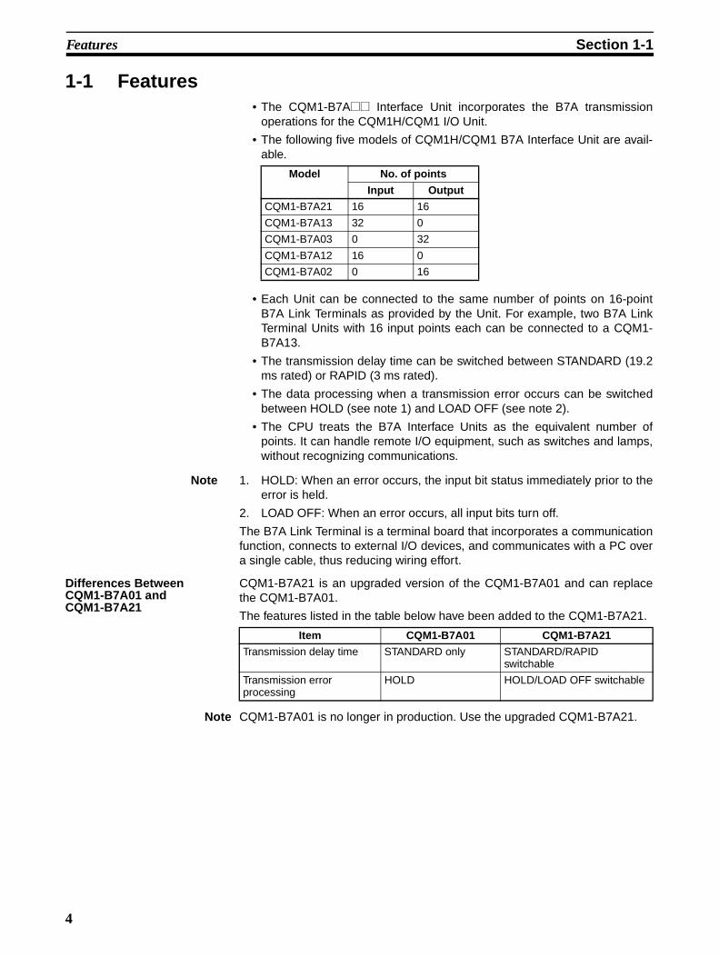
1-1 Features• The CQM1-B7A@@ Interface Unit incorporates the B7A transmission
operations for the CQM1H/CQM1 I/O Unit.
• The following five models of CQM1H/CQM1 B7A Interface Unit are avail-able.
• Each Unit can be connected to the same number of points on 16-pointB7A Link Terminals as provided by the Unit. For example, two B7A LinkTerminal Units with 16 input points each can be connected to a CQM1-B7A13.
• The transmission delay time can be switched between STANDARD (19.2ms rated) or RAPID (3 ms rated).
• The data processing when a transmission error occurs can be switchedbetween HOLD (see note 1) and LOAD OFF (see note 2).
• The CPU treats the B7A Interface Units as the equivalent number ofpoints. It can handle remote I/O equipment, such as switches and lamps,without recognizing communications.
Note 1. HOLD: When an error occurs, the input bit status immediately prior to theerror is held.
2. LOAD OFF: When an error occurs, all input bits turn off.
The B7A Link Terminal is a terminal board that incorporates a communicationfunction, connects to external I/O devices, and communicates with a PC overa single cable, thus reducing wiring effort.
Differences Between CQM1-B7A01 and CQM1-B7A21
CQM1-B7A21 is an upgraded version of the CQM1-B7A01 and can replacethe CQM1-B7A01.
The features listed in the table below have been added to the CQM1-B7A21.
Note CQM1-B7A01 is no longer in production. Use the upgraded CQM1-B7A21.
Model No. of points
Input Output
CQM1-B7A21 16 16
CQM1-B7A13 32 0
CQM1-B7A03 0 32
CQM1-B7A12 16 0
CQM1-B7A02 0 16
Item CQM1-B7A01 CQM1-B7A21
Transmission delay time STANDARD only STANDARD/RAPID switchable
Transmission error processing
HOLD HOLD/LOAD OFF switchable
4
System Configuration Section 1-2
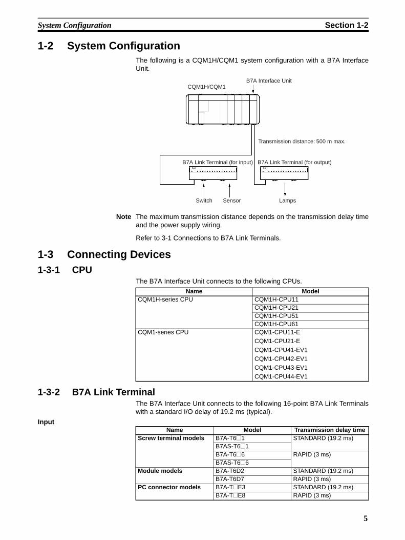
1-2 System ConfigurationThe following is a CQM1H/CQM1 system configuration with a B7A InterfaceUnit.
Note The maximum transmission distance depends on the transmission delay timeand the power supply wiring.
Refer to 3-1 Connections to B7A Link Terminals.
1-3 Connecting Devices1-3-1 CPU
The B7A Interface Unit connects to the following CPUs.
1-3-2 B7A Link TerminalThe B7A Interface Unit connects to the following 16-point B7A Link Terminalswith a standard I/O delay of 19.2 ms (typical).
Input
CQM1H/CQM1B7A Interface Unit
Transmission distance: 500 m max.
B7A Link Terminal (for input) B7A Link Terminal (for output)
Switch Sensor Lamps
Name ModelCQM1H-series CPU CQM1H-CPU11
CQM1H-CPU21CQM1H-CPU51CQM1H-CPU61
CQM1-series CPU CQM1-CPU11-ECQM1-CPU21-E
CQM1-CPU41-EV1CQM1-CPU42-EV1CQM1-CPU43-EV1
CQM1-CPU44-EV1
Name Model Transmission delay timeScrew terminal models B7A-T6@1 STANDARD (19.2 ms)
B7AS-T6@1B7A-T6@6 RAPID (3 ms)B7AS-T6@6
Module models B7A-T6D2 STANDARD (19.2 ms)B7A-T6D7 RAPID (3 ms)
PC connector models B7A-T@E3 STANDARD (19.2 ms)B7A-T@E8 RAPID (3 ms)
5
Word Allocation Section 1-4
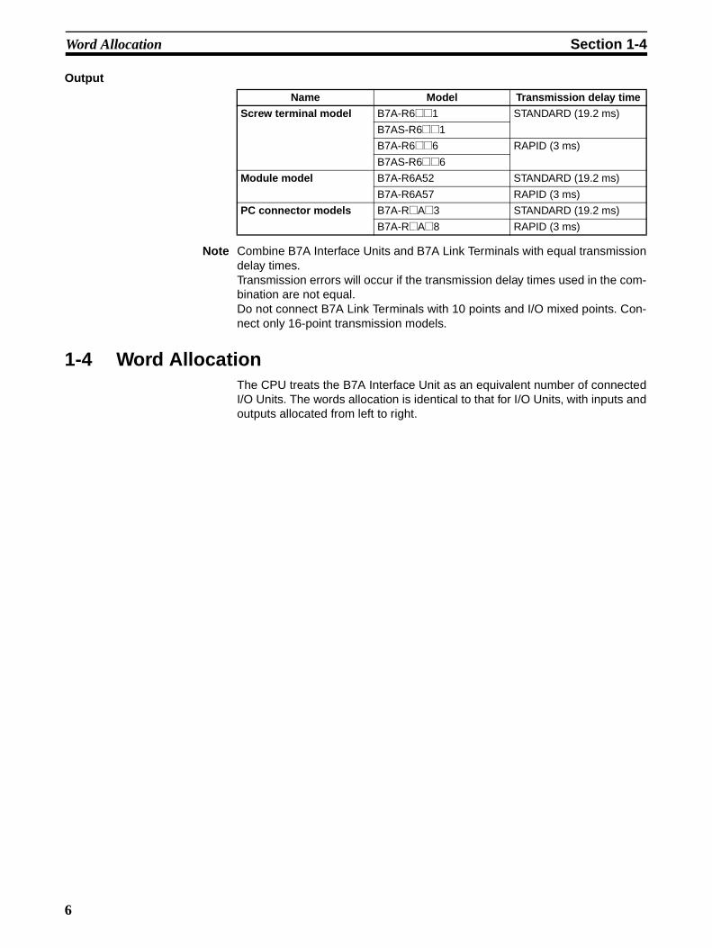
Output
Note Combine B7A Interface Units and B7A Link Terminals with equal transmissiondelay times. Transmission errors will occur if the transmission delay times used in the com-bination are not equal. Do not connect B7A Link Terminals with 10 points and I/O mixed points. Con-nect only 16-point transmission models.
1-4 Word AllocationThe CPU treats the B7A Interface Unit as an equivalent number of connectedI/O Units. The words allocation is identical to that for I/O Units, with inputs andoutputs allocated from left to right.
Name Model Transmission delay time
Screw terminal model B7A-R6@@1 STANDARD (19.2 ms)
B7AS-R6@@1
B7A-R6@@6 RAPID (3 ms)
B7AS-R6@@6
Module model B7A-R6A52 STANDARD (19.2 ms)
B7A-R6A57 RAPID (3 ms)
PC connector models B7A-R@A@3 STANDARD (19.2 ms)
B7A-R@A@8 RAPID (3 ms)
6
Bit Allocation Section 1-5
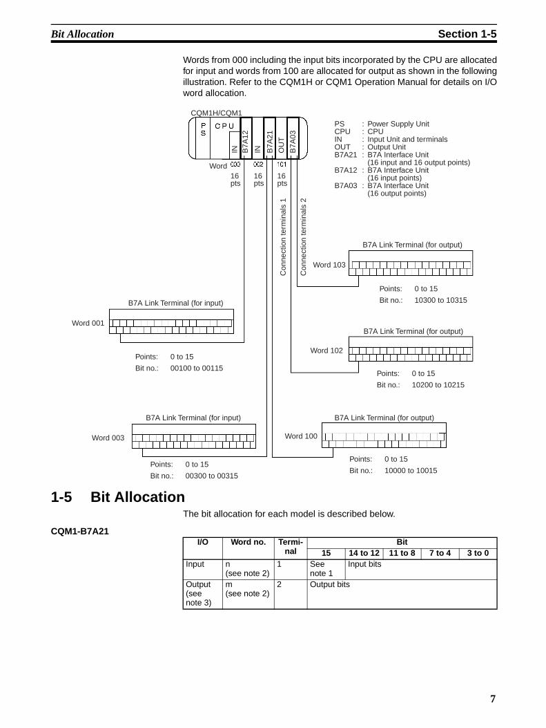
Words from 000 including the input bits incorporated by the CPU are allocatedfor input and words from 100 are allocated for output as shown in the followingillustration. Refer to the CQM1H or CQM1 Operation Manual for details on I/Oword allocation.
1-5 Bit AllocationThe bit allocation for each model is described below.
CQM1-B7A21
PS : Power Supply UnitCPU : CPUIN : Input Unit and terminalsOUT : Output UnitB7A21 : B7A Interface Unit
(16 input and 16 output points)B7A12 : B7A Interface Unit
(16 input points)B7A03 : B7A Interface Unit
(16 output points)
16 pts
B7A Link Terminal (for input)
B7A Link Terminal (for input)
B7A Link Terminal (for output)
B7A Link Terminal (for output)
B7A Link Terminal (for output)
16 pts
16 pts
IN IN OU
T
B7A
12
B7A
21
B7A
03
Word
Con
nect
ion
term
inal
s 1
Points: 0 to 15
Bit no.: 00100 to 00115
Points: 0 to 15
Bit no.: 10300 to 10315
Points: 0 to 15
Bit no.: 00300 to 00315
Points: 0 to 15
Bit no.: 10200 to 10215
Points: 0 to 15
Bit no.: 10000 to 10015
Con
nect
ion
term
inal
s 2
Word 102
Word 003
Word 103
Word 100
Word 001
CQM1H/CQM1
I/O Word no. Termi-nal
Bit15 14 to 12 11 to 8 7 to 4 3 to 0
Input n (see note 2)
1 See note 1
Input bits
Output (see note 3)
m (see note 2)
2 Output bits
7

Bit Allocation Section 1-5
CQM-B7A13
CQM1-B7A03
CQM1-B7A12
CQM1-B7A02
Note 1. Bit 15 of the input address is allocated as follows, according to the DIPswitch input mode setting.
15-point input + 1 error mode setting = transmission error bit
16-point input = input bit 15
Refer to 2-2 Switch Settings.
2. Start word address (n: input, m: output)
3. See the following caution.
!Caution The minimum input time (minimum required time to read input signal fromCPU) at output bit of the B7A Interface Unit is as follows:
When a user program is created, make sure the ON/OFF signal range fromthe CPU to the B7A Interface Unit’s output bit is larger than the above values.If smaller than the above values, data might not be correct transmitted.
Transmission Errors
Power On If the input mode is set to 15IN+ERR, the transmission error bit becomes OFFwhen the CQM1H/CQM1 power is turned on.
The transmission error bit turns ON if normal transmission with the input B7ALink Terminal is not established within 10 ms.
All input bits remain OFF from the time CQM1H/CQM1 is turned on until nor-mal transmission is established.
I/O Word no. Termi-nal
Bit15 14 to 12 11 to 8 7 to 4 3 to 0
Input n 1 See note 1
Input bits
Input n + 1 2 See note 1
Input bits
I/O Word no. Termi-nal
Bit15 to 12 11 to 8 7 to 4 3 to 0
Output (see note 3)
m 1 Output bits
Output (see note 3)
m + 1 2 Output bits
I/O Word no. Termi-nal
Bit15 14 to 12 11 to 8 7 to 4 3 to 0
Input n 1 See note 1
Input bits
I/O Word no. Termi-nal
Bit15 to 12 11 to 8 7 to 4 3 to 0
Output (see note 3)
m 1 Output bits
Transmission delay time Minimum input time
STANDARD (19.2 ms) 16 ms
RAPID (3 ms) 2.4 ms
8

Bit Allocation Section 1-5
Inputs When a transmission error occurs, the input bits are processed according tothe transmission error processing setting: HOLD or LOAD OFF.
If the input mode is set to 15IN+ERR, the transmission error bit turns ON.
The transmission error bit turns OFF when normal transmission is re-estab-lished.
The normally received signals are then input to the input bits.
Outputs A transmission error with an output B7A Link Terminal can only be detected atthe Link Terminal. Confirm the error with the Link Terminal ERR indicator anderror output.
9


SECTION 2Nomenclature and Settings
This section provides the nomenclature and switch settings for the CQM1-B7A@@ Interface Units.
2-1 Nomenclature . . . . . . . . . . . . . . . . . . . . . . . . . . . . . . . . . . . . . . . . . . . . . . . . . 12
2-2 Switch Settings . . . . . . . . . . . . . . . . . . . . . . . . . . . . . . . . . . . . . . . . . . . . . . . . 17
11

Nomenclature Section 2-1
2-1 Nomenclature
CQM1-B7A21
Front View
Indicators
Indicators (see following table)
B7A Link Terminal connection terminals 1For connection of a 16-point output B7A Link Terminal.
External power terminalsRequired for transmission with the B7A Link Terminal. Con-nect a 12- to-24 VDC power supply.
Terminal screws: M3(Optimum tightening torque: 0.5 N • m)
B7A Link Terminal connection terminals 2For connection of a 16-point Input B7A Link Terminal.
Name Color Function
RDY Unit ready Green Lit while the CQM1H/CQM1 is supplied with power.
ERR Input transmission error
Red Lit if the B7A Link Terminal for input is mal-functioning or the B7A Link Terminal for input is disconnected.
3ms Transmission delay time
Orange Lit while transmission delay time is set to RAPID (3 ms). Not lit when set to STAN-DARD (19.2 ms).
LOAD OFF
Transmission error processing
Orange Lit while transmission error processing is set to LOAD OFF. Not lit when set to HOLD.
15IN+ERR Input mode Orange Lit while input mode is set to 15IN+ERR. Not lit when set to 16IN.
12

Nomenclature Section 2-1
CQM1-B7A13
Front View
Indicators
Indicators (see following table)
B7A Link Terminal connection terminals 1For connection of a 16-point Input B7A Link Terminal. Inputs least-significant word (n) data.
External power terminalsRequired for transmission with the B7A Link Terminal. Con-nect a 12- to 24-VDC power supply.
Terminal screws: M3(Optimum tightening torque: 0.5 N • m)
B7A Link Terminal connection terminals 2For connection of a 16-point Input B7A Link Terminal. Inputs most-significant word (n+1) data.
Name Color Function
RDY Unit ready Green Lit while the CQM1H/CQM1 is supplied with power.
3ms Transmission delay time
Orange Lit while transmission delay time is set to RAPID (3 ms). Not lit when set to STAN-DARD (19.2 ms).
LOAD OFF
Transmission error processing
Orange Lit while transmission error processing is set to LOAD OFF. Not lit when set to HOLD.
15IN+ERR Input mode Orange Lit while input mode is set to 15IN+ERR. Not lit when set to 16IN.
ERR1 Input 1 transmission error
Red Lit when normal transmission with the Input B7A Link Terminal connected to connection terminals 1 is not possible or when no Input B7A Link Terminal is connected.
ERR2 Input 2 transmission error
Red Lit when normal transmission with the Input B7A Link Terminal connected to connection terminals 2 is not possible or when no Input B7A Link Terminal is connected.
13

Nomenclature Section 2-1
CQM1-B7A03
Front View
Indicators
Indicators (see following table)
B7A Link Terminal connection terminals 1For connection of a 16-point output B7A Link Terminal. outputs least-significant word (m) data.
External power terminalsRequired for transmission with the B7A Link Terminal. Con-nect a 12- to 24-VDC power supply.
Terminal screws: M3(Optimum tightening torque: 0.5 N • m)
B7A Link Terminal connection terminals 2For connection of a 16-point output B7A Link Terminal. outputs most-significant word (m+1) data.
Name Color Function
RDY Unit ready Green Lit while the CQM1H/CQM1 is supplied with power.
19ms/3ms Transmission delay time
Orange Lit while transmission delay time is set to RAPID (3 ms). Not lit when set to STAN-DARD (19.2 ms).
14

Nomenclature Section 2-1
CQM1-B7A12
Front View
Indicators
Indicators (see following table)
B7A Link Terminal connection terminals 1For connection of a 16-point Input B7A Link Terminal.
External power terminalsRequired for transmission with the B7A Link Terminal. Con-nect a 12- to-24 VDC power supply.
Terminal screws: M3(Optimum tightening torque: 0.5 N • m)
Name Color Function
RDY Unit ready Green Lit while the CQM1H/CQM1 is supplied with power.
ERR Input transmission error
Red Lit if the B7A Link Terminal for input is mal-functioning or the B7A Link Terminal for input is disconnected.
3ms Transmission delay time
Orange Lit while transmission delay time is set to RAPID (3 ms). Not lit when set to STAN-DARD (19.2 ms).
LOAD OFF
Transmission error processing
Orange Lit while transmission error processing is set to LOAD OFF. Not lit when set to HOLD.
15IN+ERR Input mode Orange Lit while input mode is set to 15IN+ERR. Not lit when set to 16IN.
15

Nomenclature Section 2-1
CQM1-B7A02
Front View
Indicators
Left-side View Common to all models.
Indicators (see following table)
B7A Link Terminal connection terminals 1For connection of a 16-point output B7A Link Terminal.
External power terminalsRequired for transmission with the B7A Link Terminal. Con-nect a 12- to 24-VDC power supply.
Terminal screws: M3(Optimum tightening torque: 0.5 N • m)
Name Color Function
RDY Unit ready Green Lit while the CQM1H/CQM1 is supplied with power.
19ms/3ms Transmission delay time
Orange Lit while transmission delay time is set to RAPID (3 ms). Not lit when set to STAN-DARD (19.2 ms).
Operation setting DIP SwitchSets to the operation of the B7A Interface Unit (see page 15). Set the switches before mounting the B7A Interface Unit in CQM1H/CQM1. To set after mounting, remove the ter-minal block and make the set-ting from the front face.
16
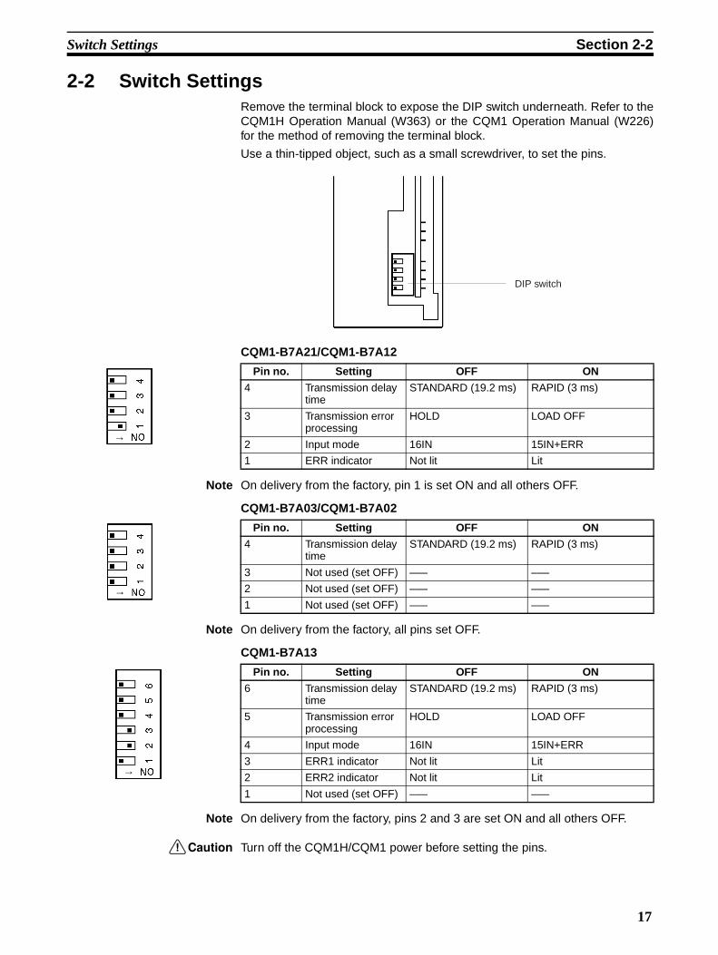
Switch Settings Section 2-2
2-2 Switch SettingsRemove the terminal block to expose the DIP switch underneath. Refer to theCQM1H Operation Manual (W363) or the CQM1 Operation Manual (W226)for the method of removing the terminal block.
Use a thin-tipped object, such as a small screwdriver, to set the pins.
CQM1-B7A21/CQM1-B7A12
Note On delivery from the factory, pin 1 is set ON and all others OFF.
CQM1-B7A03/CQM1-B7A02
Note On delivery from the factory, all pins set OFF.
CQM1-B7A13
Note On delivery from the factory, pins 2 and 3 are set ON and all others OFF.
!Caution Turn off the CQM1H/CQM1 power before setting the pins.
Pin no. Setting OFF ON
4 Transmission delay time
STANDARD (19.2 ms) RAPID (3 ms)
3 Transmission error processing
HOLD LOAD OFF
2 Input mode 16IN 15IN+ERR
1 ERR indicator Not lit Lit
DIP switch
→
Pin no. Setting OFF ON
4 Transmission delay time
STANDARD (19.2 ms) RAPID (3 ms)
3 Not used (set OFF) ––– –––
2 Not used (set OFF) ––– –––
1 Not used (set OFF) ––– –––→
Pin no. Setting OFF ON
6 Transmission delay time
STANDARD (19.2 ms) RAPID (3 ms)
5 Transmission error processing
HOLD LOAD OFF
4 Input mode 16IN 15IN+ERR
3 ERR1 indicator Not lit Lit
2 ERR2 indicator Not lit Lit
1 Not used (set OFF) ––– –––
→
17

Switch Settings Section 2-2
Transmission Delay Time Setting
Sets the transmission delay time for the B7A Interface Unit.
Set the transmission delay time to RAPID to enable transmission with high-speed B7A Link Terminals with a transmission delay time of 3 ms. Set thetransmission delay time to STANDARD to enable transmission with standardB7A Link Terminals with a transmission delay time of 19.2 ms.
Set the pin to match the transmission delay time of the type of B7A Link Ter-minal connected. A transmission error will occur if the setting does not matchthe transmission delay time of the B7A Link Terminal.
The transmission delay time setting is made for the entire Unit. It is not possi-ble to make separate settings for each word if multiple words are used.
Transmission Error Processing Setting
This setting determines whether the input bit status immediately prior to theerror is held when a transmission error occurs (HOLD) or whether all input bitsturn off (LOAD OFF).
Input Mode Setting Set the input mode (the use of bit 15) from the Input B7A Link Terminal to oneof the modes shown in the table below. Match the pin setting to the Input B7ALink Terminal.
ERR Indicator Lighting Setting
Sets whether the ERR indicator lights when an input transmission erroroccurs.
To avoid indicator lighting unnecessarily, set pin OFF if the input side of theB7A Interface Unit is not used.
Setting Transmission Delay Time
ON RAPID (3 ms)
OFF STANDARD (19.2 ms) (factory setting)
Setting Transmission error processing
ON LOAD OFF
OFF HOLD (factory setting)
Setting Input mode Description
ON 15-point input + 1 error (15IN+ERR)
Bit 15 used as transmission error bit. The bits available for input are the 15 bits from 00 to 14.
OFF 16-point input (16IN) Bit 15 also used as a normal input bit. The bits available for input are the 16 bits from 00 to 15. (factory setting)
Setting Description
ON ERR indicator lights (factory setting)
OFF ERR indicator does not light
18

SECTION 3Connections
This section describes the connections between the CQM1-B7A@@ Interface Units and B7A Link Terminals.
3-1 Connections to B7A Link Terminals. . . . . . . . . . . . . . . . . . . . . . . . . . . . . . . . 20
3-1-1 Recommended Cables . . . . . . . . . . . . . . . . . . . . . . . . . . . . . . . . . . . 20
3-1-2 Connecting Terminals . . . . . . . . . . . . . . . . . . . . . . . . . . . . . . . . . . . . 20
3-2 Wiring . . . . . . . . . . . . . . . . . . . . . . . . . . . . . . . . . . . . . . . . . . . . . . . . . . . . . . . 22
19

Connections to B7A Link Terminals Section 3-1
3-1 Connections to B7A Link Terminals
3-1-1 Recommended CablesThe B7A Interface Unit can be connected to the input and output B7A LinkTerminals using the following cables.
Standard Transmission Delay-time Type
Cabtire Cable Use a VCTF 0.75 x 3 C cabtire cable (100 m max.) if a power supply is sharedand a VCTF 0.75 x 2 C cabtire cable (500 m max.) if power is supplied inde-pendently.
Rapid Transmission Delay-time Type
Shielded Cable Use a 0.75 x 3 C shielded cable (50 m max.) if a power supply is shared and a0.75 x 2 C shielded cable (100 m max.) if power is supplied independently.
!Caution If shielded cable is not used for the high-speed transmission delay-time LinkTerminal, the transmission distance is not to exceed 10 m regardless ofwhether power supply is shared or wired separately.
3-1-2 Connecting TerminalsConnect the input and output B7A Link Terminals to the B7A Interface Unit viathe following terminals using crimp-style terminals used for CQM1H/CQM1 I/O Units.
CQM1-B7A21
CQM1-B7A13
Unused
Connect to the SIG terminal of the output B7A Link terminal.
Connect to the negative power supply ter-minal of the output B7A Link Terminal.
Connect to the SIG terminal of the input B7A Link Terminal.
Connect to the negative power supply ter-minal of the input B7A Link Terminal.
A0
A1
A2
A3
B0
B1
B2
B3
Word m
Word n
Unused
Connect to the SIG terminal of the input B7A Link terminal.
Connect to the negative power supply ter-minal of the input B7A Link Terminal.
Connect to the SIG terminal of the input B7A Link Terminal.
Connect to the negative power supply ter-minal of the input B7A Link Terminal.
A0
A1
A2
A3
B0
B1
B2
B3
Word n
Word n + 1
20

Connections to B7A Link Terminals Section 3-1
CQM1-B7A03
CQM1-B7A12
CQM1-B7A02
Connectors Crimp connectors for I/O Unit wiring should be less than 6.2 mm wide (M3),
and the wire should be AWG22 to 18 (0.3 to 0.75 mm2).
Terminal screws should be tightened with a torque of 0.5 N • m.
!Caution Forked crimp connectors are required by UL and CSA standards.
Unused
Connect to the SIG terminal of the output B7A Link terminal.
Connect to the negative power supply ter-minal of the output B7A Link Terminal.
Connect to the SIG terminal of the output B7A Link Terminal.
Connect to the negative power supply ter-minal of the output B7A Link Terminal.
A0
A1
A2
A3
B0
B1
B2
B3
Word m
Word m + 1
Unused
Connect to the SIG terminal of the input B7A Link terminal.
Connect to the negative power supply ter-minal of the input B7A Link Terminal.
A0
A1
A2
A3
B0
B1
B2
B3
Word n
Unused
Unused
Connect to the SIG terminal of the output B7A Link terminal.
Connect to the negative power supply ter-minal of the output B7A Link Terminal.
A0
A1
A2
A3
B0
B1
B2
B3
Word m
Unused
6.2 mm max.6.2 mm max.
21

Wiring Section 3-2
3-2 WiringWiring between the B7A Interface Unit, input B7A Link Terminal, and outputB7A Link Terminal sharing a single power supply differs from wiring betweenUnits using independent power supplies as shown in the following diagrams.
Standard Transmission Delay-time Link Terminal
Single Power Supply
Independent Power Supplies
Note 1. The transmission distance depends on the type of wiring used.
2. The size of terminal screw differs for the B7A Interface Unit and B7A LinkTerminal. Consider the size of the terminal screws when using crimped ter-minals.
B7A Interface Unit
B7A Link Terminal
+
12 to 24 VDC
–
–
Transmission distance: 100 m max.
Transmission cable: VCTF 0.75 mm2 min.
B7A Link Terminal
Terminal screws: M3
Terminal screws: M3.5
B7A Interface Unit
B7A Link Terminal
+
+
+
12 to 24 VDC
12 to 24 VDC
12 to 24 VDC
Transmission distance: 500 m max.
Transmission cable: VCTF 0.75 mm2 min.
–
–
B7A Link Terminal
Terminal screws: M3
Terminal screws: M3.5
22

Wiring Section 3-2
3. Locate transmission cables away from power cables and high-voltage ca-bles to eliminate the effects of noise.
Rapid Transmission Delay-time Link Terminal
Single Power Supply
Independent Power Supplies
Note 1. The transmission distance depends on the type of wiring used.
2. The size of terminal screw differs for the B7A Interface Unit and B7A LinkTerminal. Consider the size of the terminal screws when using crimped ter-minals.
3. It is recommend that the shield wire be grounded.
B7A Interface Unit
B7A Link Terminal
+
12 to 24 VDC
–
Transmission distance: 50 m max.
Transmission cable: shielded, 0.75 mm2 min.
B7A Link Terminal
Terminal screws: M3
Terminal screws: M3.5
–
Shielded cable: 0.75 mm2 min.Ground
Ground
Terminal screws: M3
Terminal screws: M3.5B7A Interface Unit
B7A Link Terminal
+
12 to 24 VDC
–
Transmission distance: 50 m max.
Transmission cable: shielded, 0.75 mm2 min.
B7A Link Terminal
– Shielded cable: 0.75 mm2 min.
Ground
Ground
+
+12 to 24 VDC
12 to 24 VDC
23

Wiring Section 3-2
4. If shielded cable is not used, the transmission distance is not to exceed10 m regardless of whether power supply is common or wired separately
(using VCTF 0.75 mm2 min.).
5. Locate transmission cables away from power cables and high-voltage ca-bles to eliminate the effects of noise.
24

Appendix ASpecifications
Standard SpecificationsThe standard specifications of the B7A Interface Unit conform to those of the CQM1H/CQM1 PC.
Performance Specifications
1. Input mode setting allows selection between 16-point input and 15-point+1 error input.
2. Input mode setting allows selection between 32-point input and 30-point+2 error input. Refer to 2-2Switch Settings.
3. The maximum transmission distance of the B7A Interface Unit varies with the transmission delay timeand the method of wiring. Refer to 3-1 Connections to B7A Link Terminals for details.
4. Minimum input time is the minimum required time to read an input signal from the CPU. The ON/OFFsignal range from the CPU to the B7A Interface Unit’s output bit should be larger than the minimuminput time.
Item Specification
I/O points B7A21: 16 input points (see note 1), 16 output pointsB7A13: 32 input points (see note 2)B7A03: 32 output points
B7A12: 16 input points (see note 1)B7A02: 16 output points
I/O word allocation B7A21: 1 word each for input and output (2 words in total)B7A13: 2 words for inputB7A03: 2 words for output
B7A12: 1 word for inputB7A02: 1 word for output
Communication method Unidirectional, time-division multiplex
Transmission distance (see note 3)
STANDARD: 500 m max.RAPID: 100 m max.
Transmission delay time STANDARD: 19.2 ms (rated delay), 31 ms max.RAPID: 3 ms (rated delay), 5 ms max.
Minimum input time(see note 4)
STANDARD: 16 msRAPID: 2.4 ms
Power consumption 100 mA at 5 VDC
External power supply 12 to 24 VDC ±10% (excluding the power required by the B7A Link Terminals)B7A21: 0.11 A min.
B7A13: 0.07 A min.B7A03: 0.10 A min.B7A12: 0.05 A min.
B7A02: 0.04 A min.
Weight 200 g max.
Dimensions 32 x 110 x 107 (W x H x D) mm
25
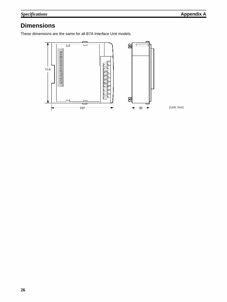
Specifications Appendix A
DimensionsThese dimensions are the same for all B7A Interface Unit models.
(Unit: mm)
26

PART IIG730 Interface Unit
CQM1-G7M21CQM1-G7N01
CQM1-G7N11
27


SECTION 1Features and System Configuration
This section describes the general features, system configuration, and word allocation of the G730 Interface Units.
1-1 Features . . . . . . . . . . . . . . . . . . . . . . . . . . . . . . . . . . . . . . . . . . . . . . . . . . . . . . 30
1-2 System Configuration . . . . . . . . . . . . . . . . . . . . . . . . . . . . . . . . . . . . . . . . . . . 31
1-3 Connecting Devices . . . . . . . . . . . . . . . . . . . . . . . . . . . . . . . . . . . . . . . . . . . . 34
1-3-1 CPU. . . . . . . . . . . . . . . . . . . . . . . . . . . . . . . . . . . . . . . . . . . . . . . . . . 34
1-3-2 G730 Remote Terminal (Slave) . . . . . . . . . . . . . . . . . . . . . . . . . . . . 34
29

Features Section 1-1
1-1 FeaturesThe CPU handles the Interface Units as I/O Units, thereby eliminating tediousprocedures. Using a G730 Interface Unit allows signals for remote I/O equip-ment, such as switches and lamps, to be handled and controlled by the G730Remote Terminal.
The G730 Remote Terminal is a terminal block with added communicationsfunctions. It is connected to remote I/O equipment and PCs. Connection tothe PC by a single pair of cables reduces wiring effort.
For more information about the G730 Remote Terminal, refer to the I/O Termi-nal Series Catalog (X044).
CQM1-G7M21 Master Switch settings on the Master allow simultaneous connection of G730Remote Terminals (Slaves) with up to 32 input points and 32 output points.
Up to two Expansion Masters can be connected to each Master (one system)to permit control of up to 128 points.
Multiple Masters can be used.
Connection of multiple Masters in separate systems permits control within therange permitted for the CPU.
The number of input points and output points can independently be switchedbetween 32 and 16.
The HOLD/HOLD OFF setting determines whether the signals into the CPUare held (HOLD) or cleared (HOLD OFF) when a transmission error occurs.
CQM1-G7N@1 Expansion Master
An Expansion Master is used if the Master alone does not allow connection ofsufficient points. The Expansion Masters are always connected in series withthe Master and up to two Expansion Masters can be connected to each Mas-ter.
Expansion Masters are available as Input Units (G7N11) and Output Units(G7N01). Switch settings allow connection of G730 Remote Terminals(Slaves) with up to 32 points.
The number of input points and output points can independently be switchedbetween 32 and 16 for both Input Units and Output Units.
30
System Configuration Section 1-2
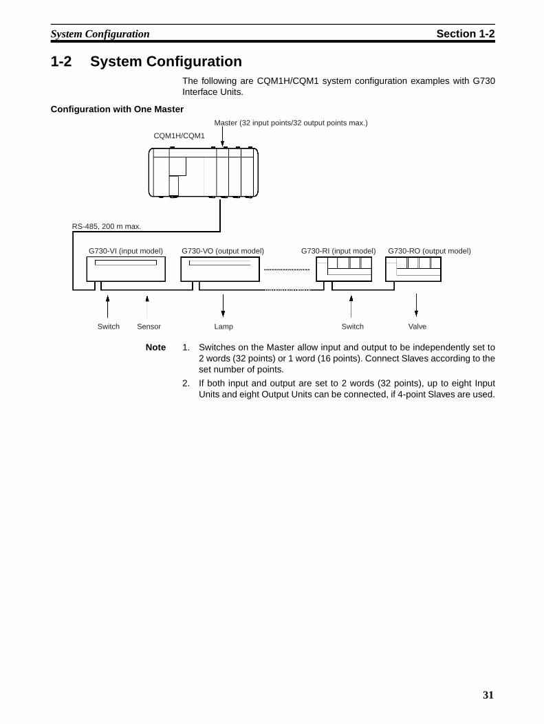
1-2 System ConfigurationThe following are CQM1H/CQM1 system configuration examples with G730Interface Units.
Configuration with One Master
Note 1. Switches on the Master allow input and output to be independently set to2 words (32 points) or 1 word (16 points). Connect Slaves according to theset number of points.
2. If both input and output are set to 2 words (32 points), up to eight InputUnits and eight Output Units can be connected, if 4-point Slaves are used.
Master (32 input points/32 output points max.)
RS-485, 200 m max.
G730-VI (input model) G730-VO (output model) G730-RI (input model) G730-RO (output model)
Switch Sensor Lamp ValveSwitch
CQM1H/CQM1
31

System Configuration Section 1-2
Configuration as a Single System with Expansion Masters
Note 1. Use one Master in any system. The systems must be separated if multipleMasters are used. (See page 33)
2. Up to two Expansion Masters can be connected to each Master.
3. When two Expansion Masters are used, set one as Unit 1 and the other asUnit 2. The Slave address for Unit 2 can only be used for an 8-point or 16-point Slave. It cannot be used for a 4-point Slave.
4. The combination of one Master with two Expansion Masters allows controlof up to 128 points.
5. The maximum number of connectable Slaves is 24 4-point Slaves and 48-point Slaves, making a total or 28 Units.
Master (32 input points/32 output points max.)Expansion Master Unit 1 (max. 32 input points or 32 output points)Expansion Master Unit 2 (max. 32 input points or 32 output points)
RS-485, 200 m max.
G730-VI (input model) G730-VO (output model) G730-RI (input model) G730-RO (output model)
Switch Sensor Lamp ValveSwitch
CQM1H/CQM1
32

System Configuration Section 1-2
Configuration as Multiple Systems
Note 1. When multiple Masters are used, allocate system numbers to them in se-quence from 1, starting from the Master nearest the CPU. The systemnumbers have no special significance. Refer to 4-1 Word Allocation.
2. Up to two Expansion Masters can be connected to each Master.
3. When two Expansion Masters are used, set one as Unit 1 and the other asUnit 2. The Slave address for Unit 2 can only be used for an 8-point or 16-point Slave. It cannot be used for a 4-point Slave.
4. Masters and Expansion Masters can be used in any combination, providedthat the maximum number of input and output points remains within therange permitted for the CPU.
Master, System 1 (32 input points/32 output points max.)Expansion Master Unit 1 (max. 32 input points or 32 output points)Expansion Master Unit 2 (max. 32 input points or 32 output points)
Master, System 2 (32 input points/32 output points max.)Expansion Master Unit 1 (max. 32 input points or 32 output points)
RS-485, 200 m max.
G730-VI (input model) G730-VO (output model) G730-RI (input model) G730-RO (output model)
Switch Sensor Lamp ValveSwitch
G730-VI (input model) G730-VO (output model) G730-RI (input model) G730-RO (output model)
Switch Sensor Lamp ValveSwitch
33

Connecting Devices Section 1-3
1-3 Connecting Devices
1-3-1 CPUThe G730 Interface Unit connects to the following CPUs.
Note The number of points includes the CPU internal 16 input points (one word).Therefore, the actual maximum numbers of points usable by the G730 Inter-face Unit are 112 points (7 words), 240 points (15 words), and 496 points (31words) respectively.
1-3-2 G730 Remote Terminal (Slave)The following G730 Remote Terminals can be connected to a G730 InterfaceUnit.
For more information about the G730 Remote Terminal, refer to the I/O Termi-nal Series Catalog (X044).
Name Model Max. I/O Points (see note)
CQM1H-series CQM1H-CPU11 256 (16 words)
CQM1H-CPU21
CQM1H-CPU51 512 (32 words)
CQM1H-CPU61
CQM1-series CQM1-CPU11-E 128 (8 words)
CQM1-CPU21-E
CQM1-CPU41-EV1 256 (16 words)
CQM1-CPU42-EV1
CQM1-CPU43-EV1
CQM1-CPU44-EV1
Model I/O type I/O points
G730-RID04 Relay input (DC) 4
G730-RIA04 Relay input (AC)
G730-ROC04 Relay output
G730-ROC04-A Relay output (with error detection function)
G730-VID04 DC input, NPN (common +)
G730-VOD04 Transistor output, NPN (common –)
G730-ROC08 Relay output 8
G730-AOM08 Relay output (power MOS FET)
G730-VID08 DC input, NPN (common +)
G730-VID08-1 DC input, PNP (common –)
G730-VOD08 Transistor output, NPN (common –)
G730-VOD08-1 Transistor output, PNP (common +)
G730-ROC16 Relay output 16
G730-AOM16 Relay output (power MOS FET)
G730-VID16 DC input, NPN (common +)
G730-VOD16 Transistor output, NPN (common –)
34

SECTION 2Nomenclature and Settings
This section provides the nomenclature and switch settings for the G730 Interface Units.
2-1 Nomenclature . . . . . . . . . . . . . . . . . . . . . . . . . . . . . . . . . . . . . . . . . . . . . . . . . 36
2-2 Switch Settings . . . . . . . . . . . . . . . . . . . . . . . . . . . . . . . . . . . . . . . . . . . . . . . . 39
35
Nomenclature Section 2-1
2-1 Nomenclature
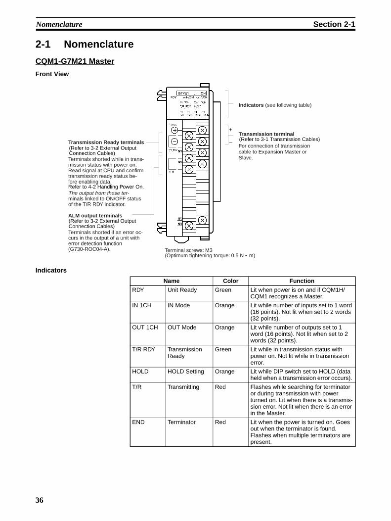
CQM1-G7M21 Master
Front View
Indicators
Terminal screws: M3(Optimum tightening torque: 0.5 N • m)
Transmission terminal
For connection of transmission cable to Expansion Master or Slave.
Indicators (see following table)
ALM output terminals
Terminals shorted if an error oc-curs in the output of a unit with error detection function (G730-ROC04-A).
Transmission Ready terminals
Terminals shorted while in trans-mission status with power on. Read signal at CPU and confirm transmission ready status be-fore enabling data.
The output from these ter-minals linked to ON/OFF status of the T/R RDY indicator.
+
–(Refer to 3-2 External Output Connection Cables)
(Refer to 3-2 External Output Connection Cables)
Refer to 4-2 Handling Power On.
(Refer to 3-1 Transmission Cables)
Name Color Function
RDY Unit Ready Green Lit when power is on and if CQM1H/CQM1 recognizes a Master.
IN 1CH IN Mode Orange Lit while number of inputs set to 1 word (16 points). Not lit when set to 2 words (32 points).
OUT 1CH OUT Mode Orange Lit while number of outputs set to 1 word (16 points). Not lit when set to 2 words (32 points).
T/R RDY Transmission Ready
Green Lit while in transmission status with power on. Not lit while in transmission error.
HOLD HOLD Setting Orange Lit while DIP switch set to HOLD (data held when a transmission error occurs).
T/R Transmitting Red Flashes while searching for terminator or during transmission with power turned on. Lit when there is a transmis-sion error. Not lit when there is an error in the Master.
END Terminator Red Lit when the power is turned on. Goes out when the terminator is found. Flashes when multiple terminators are present.
36

Nomenclature Section 2-1
Note ALM Output:The Slave address and bit address cannot be checked after a failure occurs.
It is not possible to differentiate between Open and Short modes.
For more information about the G730 Remote Terminal, refer to the I/O Termi-nal Series Catalog (X044).
CQM1-G7N11 Input Master
Front View
Indicators
NODE Slave Setting Error
Red Lit when Slave set to #28 to #30. Flashes for other address setting error (refer to Appendix B Troubleshooting for details).
ALM Slave Alarm Red Lit after error occurs with Slave output (G730-ROC04-A).
Name Color Function
Terminal screws: M3(Optimum tightening torque: 0.5 N • m)
Transmission terminal 1For connection of transmission cable from Master or Expansion Master.
Indicators (see following table)
+
–
Transmission terminal 2For connection of transmission cable to next Expansion Master or Slave.
+
–
(see page 44)
(see page 44)
Name Color Function
RDY Unit Ready Green Lit when power is on and if CQM1H/CQM1 recognizes a Master.
IN 1CH IN Mode Orange Lit while number of inputs set to 1 word (16 points). Not lit when set to 2 words (32 points).
ADR No.2 Unit 2 Orange Lit when Unit 2 set. Not lit when Unit 1 set.
T/R Transmitting Red Flashes during transmission with power turned on. Lit when there is a transmis-sion error. Not lit when there is an error in the Expansion Master.
37
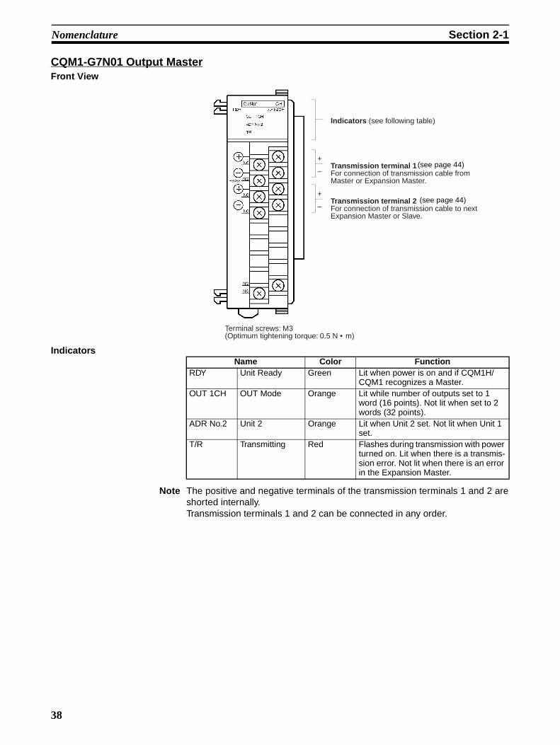
Nomenclature Section 2-1
CQM1-G7N01 Output MasterFront View
Indicators
Note The positive and negative terminals of the transmission terminals 1 and 2 areshorted internally.Transmission terminals 1 and 2 can be connected in any order.
Terminal screws: M3(Optimum tightening torque: 0.5 N • m)
Indicators (see following table)
+
–
+
–
Transmission terminal 1For connection of transmission cable from Master or Expansion Master.
Transmission terminal 2For connection of transmission cable to next Expansion Master or Slave.
(see page 44)
(see page 44)
Name Color FunctionRDY Unit Ready Green Lit when power is on and if CQM1H/
CQM1 recognizes a Master.OUT 1CH OUT Mode Orange Lit while number of outputs set to 1
word (16 points). Not lit when set to 2 words (32 points).
ADR No.2 Unit 2 Orange Lit when Unit 2 set. Not lit when Unit 1 set.
T/R Transmitting Red Flashes during transmission with power turned on. Lit when there is a transmis-sion error. Not lit when there is an error in the Expansion Master.
38
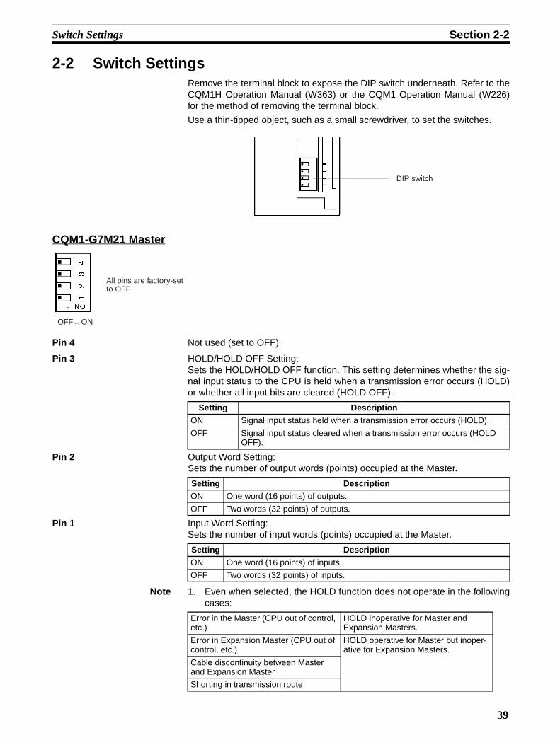
Switch Settings Section 2-2
2-2 Switch SettingsRemove the terminal block to expose the DIP switch underneath. Refer to theCQM1H Operation Manual (W363) or the CQM1 Operation Manual (W226)for the method of removing the terminal block.
Use a thin-tipped object, such as a small screwdriver, to set the switches.
CQM1-G7M21 Master
Pin 4 Not used (set to OFF).
Pin 3 HOLD/HOLD OFF Setting:Sets the HOLD/HOLD OFF function. This setting determines whether the sig-nal input status to the CPU is held when a transmission error occurs (HOLD)or whether all input bits are cleared (HOLD OFF).
Pin 2 Output Word Setting:Sets the number of output words (points) occupied at the Master.
Pin 1 Input Word Setting:Sets the number of input words (points) occupied at the Master.
Note 1. Even when selected, the HOLD function does not operate in the followingcases:
DIP switch
All pins are factory-set to OFF
OFF↔ON
→
Setting Description
ON Signal input status held when a transmission error occurs (HOLD).
OFF Signal input status cleared when a transmission error occurs (HOLD OFF).
Setting Description
ON One word (16 points) of outputs.
OFF Two words (32 points) of outputs.
Setting Description
ON One word (16 points) of inputs.
OFF Two words (32 points) of inputs.
Error in the Master (CPU out of control, etc.)
HOLD inoperative for Master and Expansion Masters.
Error in Expansion Master (CPU out of control, etc.)
HOLD operative for Master but inoper-ative for Expansion Masters.
Cable discontinuity between Master and Expansion Master
Shorting in transmission route
39

Switch Settings Section 2-2
2. Disconnection between Slaves:HOLD operative for Slaves connected to Master. Inoperative for outputSlaves after the discontinuity. These statuses determined by the outputSlave HOLD/HOLD OFF setting.
CQM1-G7N11 Input Expansion Master
Pins 3 and 4 Not used (set to OFF).
Pin 2 Expansion Master Unit # Setting:Sets the Expansion Master Unit Number
Pin 1 Input Word Setting:Sets the number of input words (points) occupied at the Expansion Master.
Note 1. Turn the CQM1H/CQM1 power off before setting the DIP switch. Theswitch settings are enabled when the CQM1H/CQM1 power is turned on.
2. Use a different Unit number for each of the two Expansion Masters usedwith a single Master.
3. Slave address for Unit 2 can only be used for an 8-point or 16-point Slave.It cannot be used for a 4-point Slave.
CQM1-G7N01 Output Expansion Master
Pins 3 and 4 Not used (set to OFF).
Pin 2 Expansion Master Unit # Setting:Sets the Expansion Master Unit Number
All pins are factory-set to OFF
OFF↔ON
→
Setting Description
ON Expansion Master is Unit 2
OFF Expansion Master is Unit 1
Setting Description
ON One word (16 points) of inputs.
OFF Two words (32 points) of inputs.
All pins are factory-set to OFF
OFF↔ON
→
Setting Description
ON Expansion Master is Unit 2
OFF Expansion Master is Unit 1
40

Switch Settings Section 2-2
Pin 1 Output Word Setting:Sets the number of output words (points) occupied at the Expansion Master.
Note 1. Turn the CQM1H/CQM1 power off before setting the DIP switch. Theswitch settings are enabled when the CQM1H/CQM1 power is turned on.
2. Use a different Unit number for each of the two Expansion Masters usedwith a single Master.
3. Slave address for Unit 2 can only be used for an 8-point or 16-point Slave.It cannot be used for a 4-point Slave.
Setting Description
ON One word (16 points) of outputs.
OFF Two words (32 points) of outputs.
41


SECTION 3Connections
This section describes the connections between the G730 Interface Units and G730 Remote Terminals.
3-1 Transmission Cables . . . . . . . . . . . . . . . . . . . . . . . . . . . . . . . . . . . . . . . . . . . . 44
3-2 External Output Connection Cables . . . . . . . . . . . . . . . . . . . . . . . . . . . . . . . . 45
43
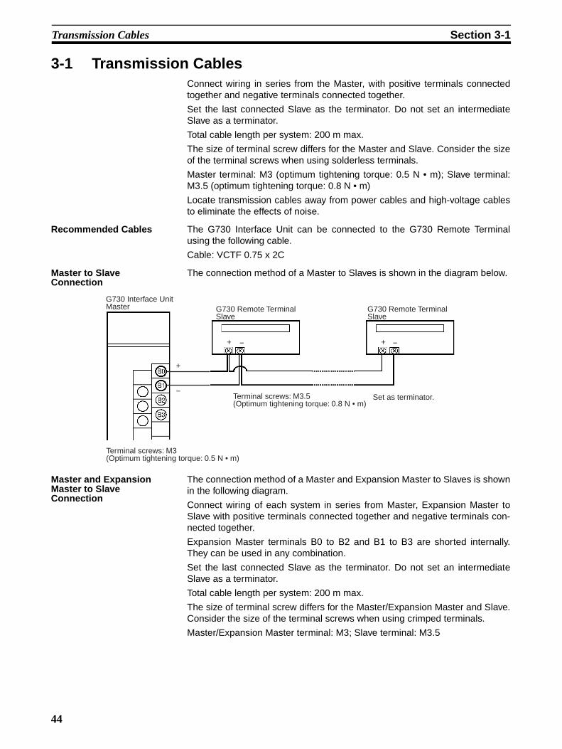
Transmission Cables Section 3-1
3-1 Transmission CablesConnect wiring in series from the Master, with positive terminals connectedtogether and negative terminals connected together.
Set the last connected Slave as the terminator. Do not set an intermediateSlave as a terminator.
Total cable length per system: 200 m max.
The size of terminal screw differs for the Master and Slave. Consider the sizeof the terminal screws when using solderless terminals.
Master terminal: M3 (optimum tightening torque: 0.5 N • m); Slave terminal:M3.5 (optimum tightening torque: 0.8 N • m)
Locate transmission cables away from power cables and high-voltage cablesto eliminate the effects of noise.
Recommended Cables The G730 Interface Unit can be connected to the G730 Remote Terminalusing the following cable.
Cable: VCTF 0.75 x 2C
Master to Slave Connection
The connection method of a Master to Slaves is shown in the diagram below.
Master and Expansion Master to Slave Connection
The connection method of a Master and Expansion Master to Slaves is shownin the following diagram.
Connect wiring of each system in series from Master, Expansion Master toSlave with positive terminals connected together and negative terminals con-nected together.
Expansion Master terminals B0 to B2 and B1 to B3 are shorted internally.They can be used in any combination.
Set the last connected Slave as the terminator. Do not set an intermediateSlave as a terminator.
Total cable length per system: 200 m max.
The size of terminal screw differs for the Master/Expansion Master and Slave.Consider the size of the terminal screws when using crimped terminals.
Master/Expansion Master terminal: M3; Slave terminal: M3.5
+
−
+ − + −
G730 Interface Unit Master G730 Remote Terminal
SlaveG730 Remote Terminal Slave
Terminal screws: M3(Optimum tightening torque: 0.5 N • m)
Terminal screws: M3.5(Optimum tightening torque: 0.8 N • m)
Set as terminator.
44

External Output Connection Cables Section 3-2
Locate transmission cables away from power cables and high-voltage cablesto eliminate the effects of noise.
3-2 External Output Connection CablesThe G730 Interface Unit Master relay contact external outputs are the Trans-mission Ready output and ALM output.
Recommended Cables The external outputs can be connected using the following cable.
Cable: AWG22 to 18 (0.3 to 0.75 mm2)
+
– +
–
+
–
+
–
+
–
+ – + –
G730 Interface Unit Master
G730 Interface Unit Ex-pansion Master
G730 Interface Unit Ex-pansion Master
G730 Remote Terminal Slave
G730 Remote Terminal Slave
Set as terminator. Terminal screws: M3.5(Optimum tightening torque: 0.8 N • m)
Terminal screws: M3(Optimum tightening torque: 0.5 N • m)
Terminal screws: M3(Optimum tightening torque: 0.5 N • m)
Terminal screws: M3(Optimum tightening torque: 0.5 N • m)
*1 *1
45

External Output Connection Cables Section 3-2
Connections Transmission Ready terminals are shorted when Transmission Ready statusoccurs.
The ALM output terminals are shorted if an error occurs in the output of a Unitwith error detection function (G730-ROC04-A).
Example of external output connections
G730 Interface Unit Master
Transmission Ready output/ALM outputMax. switching capacity: 24 VDC/2 AMin. switching capacity: 5 VDC/10 mA
Transmission Ready output
to CQM1H/CQM1 Input Unit, etc.
Power supply
Emergency stop circuit
To system control circuitALM output
Terminal screws: M3(Optimum tightening torque: 0.5 N • m)
46

SECTION 4Operation
This section provides the operational procedures for the G730 Interface Unit.
4-1 Word Allocation . . . . . . . . . . . . . . . . . . . . . . . . . . . . . . . . . . . . . . . . . . . . . . . 48
4-1-1 CQM1H/CQM1 Word Allocation . . . . . . . . . . . . . . . . . . . . . . . . . . 48
4-1-2 Precautions . . . . . . . . . . . . . . . . . . . . . . . . . . . . . . . . . . . . . . . . . . . . 49
4-1-3 G730 Remote Terminal Allocation. . . . . . . . . . . . . . . . . . . . . . . . . . 51
4-1-4 Word Allocation Example . . . . . . . . . . . . . . . . . . . . . . . . . . . . . . . . 53
4-2 Handling Power On. . . . . . . . . . . . . . . . . . . . . . . . . . . . . . . . . . . . . . . . . . . . . 54
4-3 Transmission Delay Time . . . . . . . . . . . . . . . . . . . . . . . . . . . . . . . . . . . . . . . . 54
47

Word Allocation Section 4-1
4-1 Word Allocation
4-1-1 CQM1H/CQM1 Word AllocationNumber of I/O Words The number of I/O words for the G730 Interface Unit Master and Expansion
Master can be switched between 1 word and 2 words using the DIP switch.The number of I/O words set affects the word allocations and number of con-nected Slaves. Set the required number of words to suit the Slave I/O type,number of points, and number of Units.
Unit Number of Expansion Master
Up to two Expansion Masters can be connected to each Master. Set a uniqueUnit number for each Expansion Master using the DIP switch. Either Expan-sion Master can be set as Unit 2, but a Slave address for Unit 2 can only beused for an 8-point or 16-point Slave. It cannot be used for a 4-point Slave.
If only one Expansion Master is used, set it as Unit 1.
Word Allocation Word addresses are allocated sequentially from left to right to all I/O and othermounted units, starting from 001 for inputs (000 is the CPU internal input) andfrom 100 for outputs, independent of the Master and Expansion Master Unitnumber.
In multiple systems (using multiple Masters), the word addresses are allo-cated to the inputs and outputs sequentially from the leftmost mounted unit,independent of the system number.
DIP Switch Set the DIP switch before turning the CQM1H/CQM1 power on. The switchsettings are enabled when the CQM1H/CQM1 power is turned on.
Example of Number of I/O Words and Unit No. Settings
The mounting positions of the Master and Expansion Master are not specifiedbut the wiring must be connected in the order: Master to Expansion Master toSlave. The I/O addresses are allocated sequentially in the order the Units aremounted (refer to 4-1-2 Precautions).
Master (G7M21)
Set OFF
HOLD function settingNumber of output words settingNumber of input words settingON: 1 word (16 points)OFF: 2 words (32 points)
Expansion Master (G7N11)
Set OFF
Unit # settingON: Unit 2OFF: Unit 1
Number of input words settingON: 1 word (16 points)OFF: 2 words (32 points)
Expansion Master (G7N01)
Set OFF
Unit # setting
Number of output words settingON: 1 word (16 points)OFF: 2 words (32 points)
All pins are factory-set to OFF.
ON: Unit 2OFF: Unit 1
48

Word Allocation Section 4-1
The Slave address for Unit 2 can only be used for an 8-point or 16-point Slave.It cannot be used for a 4-point Slave.
4-1-2 PrecautionsAvoid the following cases, which lead to complex word allocation and wiringconnections.
Expansion Master Unit No. Out of Mounting Order
Take care of the allocation of Expansion Master Unit 1 and Unit 2 wordaddresses.
If one Expansion Master is used for input and another for output, take carethat the Expansion Master Unit numbers and the Unit 1/Unit 2 Slave addresssettings are not reversed.
A 4-point Slave cannot be used as a Unit 2 Slave address.
System 1
Master (G7M21)
Number inputs: 2 wordsNumber of outputs: 2 words
Number of output words settingNumber of input words setting
Expansion Master (G7N01)
Set as Unit 1Number of outputs: 1 word
Unit # setting
Number of output words setting
Expansion Master (G7N11)
Set as Unit 2Number of inputs: 1 word
Unit # settingNumber of input words setting
System 2
Master (G7M21)
Number inputs: 2 wordsNumber of outputs: 1 word
Number of output words settingNumber of input words setting
Expansion Master (G7N11)
Set as Unit 1Number of inputs: 1 word
Unit # settingNumber of input words setting
CQM1H/CQM1
System 1
I/O Output
System 2
Input I/O Input
16 points
16 points
Mas
ter
Exp
ansi
on M
aste
rU
nit 1
Exp
ansi
on M
aste
rU
nit 2
Mas
ter
Exp
ansi
on M
aste
rU
nit 1
Unit
Input word
Output word
→ →
→ →
→
49

Word Allocation Section 4-1
Connect the transmission cables in series from the Master, regardless of theUnit number settings.
Expansion Masters Mounted Left of the Master
Take care of the allocation of Master, Expansion Master Unit 1 and Unit 2word addresses.
If one Expansion Master is used for input and another for output, take carethat the Expansion Master Unit numbers and the Unit 1/Unit 2 Slave addresssettings are not reversed.
A 4-point Slave cannot be used as a Unit 2 Slave address.
Connect the transmission cables in series from the Master.
I/O Input
Mas
ter
Exp
ansi
on M
aste
rU
nit 1
Exp
ansi
on M
aste
rU
nit 2
Unit
Input word
Output word
Input
16 points
16 points
CQM1H/CQM1
I/OOutput
Mas
ter
Exp
ansi
on M
aste
rU
nit 1
Exp
ansi
on M
aste
rU
nit 2
Unit
Input word
Output word
Input
16 points
16 points
CQM1H/CQM1
50

Word Allocation Section 4-1
Additional Unit Mounted Between Master and Expansion Master or Between Two Expansion Masters
Take care of the allocation of Expansion Master word addresses.
Master of Another System is Mounted Between the Master and Expansion Master or Between Two Expansion Masters of a System
Take care that the transmission cables of System 1 and System 2 are notwired together. Each system must be wired separately.
4-1-3 G730 Remote Terminal AllocationSlave Address Allocation Using one Master and two Expansion Masters in one system allows the con-
nection of up to 28 Slaves (G730 Remote Terminals).
Use the DIP switch to set the Slave address for each Slave to a value from #0to #27. Addresses #24 to #27 cannot be set for 4-point Slaves. The Masterand Expansion Masters recognize the controlled Slave by the Slave address.
I/O Output
Mas
ter
Exp
ansi
on M
aste
rU
nit 1
Exp
ansi
on M
aste
rU
nit 2
Unit
Input word
Output word
Input
16 points
16 points
16 points
CQM1H/CQM1
System 1
I/O Output
Mas
ter
Exp
ansi
on M
aste
rU
nit 1
Exp
ansi
on M
aste
rU
nit 2
Unit
Input word
Output word
Input
16 points
16 points
System 1
System 2
Mas
ter
CQM1H/CQM1
51

Word Allocation Section 4-1
Relationship Between Master/Expansion Masters and Slave Address
The Slave addresses corresponding (i.e. controlled by) each Master/Expan-sion Master are shown in the table below.
The Slave addresses corresponding to each Master and Expansion MasterUnit number are fixed.
Note 1. Addresses n,m,j,k are the start addresses allocated in CQM1H/CQM1 forthe Master or Expansion Master, as shown above.
2. Expansion Master Unit 2 is for 8-/16-point Slaves only. Do not set 4-pointSlave addresses between #24 and #27.
3. If the number of I/O words for the Master and Expansion Master is set to 1word (16 points), the corresponding Slave address (n+1), (m+1), (j+1),(k+1) (the shaded areas) are invalid. An error results if these settings areincorrect. In particular, if the Master output is set to 1 word but the outputSlave address is mistakenly set between #4 and #7, the Slave outputs thesame data as the n address. All Slave outputs corresponding to the Expan-sion Master are OFF (0).
4. The following bits are allocated as Master and Expansion Master address-es and cannot be used by the Slaves.Input bits: always OFFOutput bits: can be used as work bits
Master/Expansion
Master
I/O type Word 4-point Slave 8-point Slave 16-point Slave
Address Bit Address Bit Address Bit
Master Output n #0 00 to 03 #0 00 to 07 #0 00 to 15
#1 04 to 07
#2 08 to 11 #2 08 to 15
#3 12 to 15
n+1 #4 00 to 03 #4 00 to 07 #4 00 to 15
#5 04 to 07
#6 08 to 11 #6 08 to 15
#7 12 to 15
Input m #8 00 to 03 #8 00 to 07 #8 00 to 15
#9 04 to 07
#10 08 to 11 #10 08 to 15
#11 12 to 15
m+1 #12 00 to 03 #12 00 to 07 #12 00 to 15
#13 04 to 07
#14 08 to 11 #14 08 to 15
#15 12 to 15
Expansion Mas-ter, Unit 1
Input (Output)
j #16 00 to 03 #16 00 to 07 #16 00 to 15
#17 04 to 07
#18 08 to 11 #18 08 to 15
#19 12 to 15
j+1 #20 00 to 03 #20 00 to 07 #20 00 to 15
#21 04 to 07
#22 08 to 11 #22 08 to 15
#23 12 to 15
Expansion Mas-ter, Unit 2
Input (Output)
k Expansion Master Unit 2 is for 8-/16-point Slaves only. Do not set 4-point Slaves between #24 and #27.
#24 00 to 07 #24 00 to 15
#25 08 to 15
k+1 #26 00 to 07 #26 00 to 15
#27 08 to 15
52

Word Allocation Section 4-1
4-1-4 Word Allocation ExampleIn this example, the Master and output Expansion Master Unit 1 are set to 2words and the Slaves comprise five 16-point Units and two 4-point Units. TheSlave I/O bit addresses corresponding to Unit I/O words and Slave addressallocations are shown in the table below.
In the following example, the Slaves are connected in order of ascendingSlave address. However, the connection order is independent of the Slaveaddress. The only requirement is that they are connected in series.
Set the Slave connected at the end as the terminator, regardless of its Slaveaddress.
I/O type CPU internal input word
Master word
Slave address Expansion Master Unit 1
word
Slave address
Output --- 100 #0 (16-point output model) 102 #16, #17 (two 4-point Out-put Units)
101 #4 (16-point output model) 103 #20 (16-point Output Unit)
Input 000 001 #8 (16-point input model) ---
002 #12 (16-point input model)
Master (I/O set to 2 words)Expansion Master Unit 1 (output set to 2 words)
#0Word 100
16-point output
Bit address (OUT)10000 to 10015
RS-485 total length 200 m
Set as terminator
#4Word 101
16-point output
Bit address (OUT)10100 to 10115
#8
Word 00116-point input
#12
Word 00216-point input
#16
Word 1024-point output
#17
Word 1024-point output
#20
Word 10316-point output
Bit address (IN)00100 to 00115
Bit address (IN)00200 to 00215
Bit address (OUT)10200 to 10203
Bit address (OUT)10204 to 10207
Bit address (OUT)10300 to 10315
CQM1H/CQM1
53

Handling Power On Section 4-2
4-2 Handling Power OnAfter the power is turned on, the Master takes several seconds to recognizeall the Slaves. To start operation immediately at power on, write a program forCQM1H/CQM1 to read the Transmission Ready signal and to wait until theTransmission Ready signal turns ON.
The Master Transmission Ready signal is connected to CPU internal input bit00000 and is used as a virtual flag by the Output Ready flag in the work bits(02000).
Program Example
The contents of DM 0000 is output to the Slave at address 100 when the Out-put Ready flag and the Transmission Ready signal from the Master are ONsimultaneously.
Connection Example
Note It takes 1 s max. for the Transmission Ready output to turn OFF after a trans-mission error occurs during normal operation.
On a transmission error, the CPU input and Slave output is determined by theHOLD function setting of each Unit.
4-3 Transmission Delay TimeThe transmission delay time arises because the G730 Interface Unit commu-nications is conducted by polling from the Master to the Expansion Mastersand Slaves.
The maximum transmission delay time (Tmax) is calculated using the follow-ing formula.
Calculation of Transmission Delay Time
Maximum transmission delay time (Tmax):
Tmax = ((no. Slaves + no. Expansion Masters + 2) x 1.2 x 2) + Slave I/O ON/OFF delay time (ms)
This calculation does not include the response times between the CQM1H/CQM1 and units.
00000 02000
Transmission Ready output
Output Ready flag
MOV(21)DM0000
100
Master
Transmission Ready output
G730-VO (output type)
#0 Word 100
+
–
24 VDC
CQM1H/CQM1
54
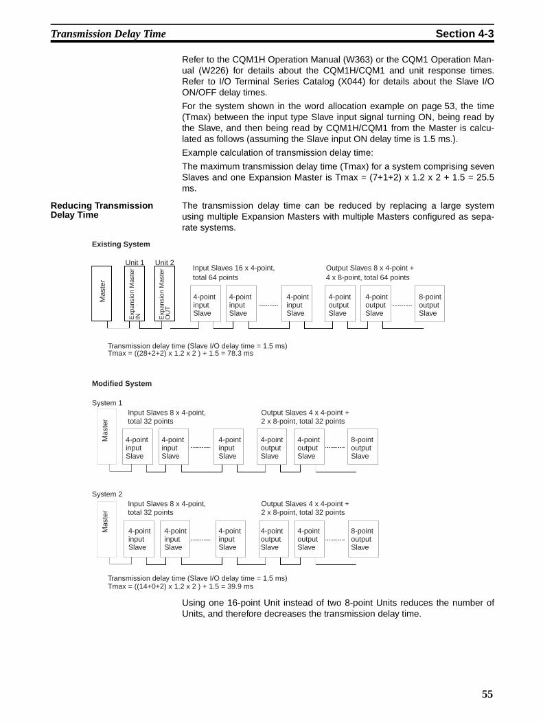
Transmission Delay Time Section 4-3
Refer to the CQM1H Operation Manual (W363) or the CQM1 Operation Man-ual (W226) for details about the CQM1H/CQM1 and unit response times.Refer to I/O Terminal Series Catalog (X044) for details about the Slave I/OON/OFF delay times.
For the system shown in the word allocation example on page 53, the time(Tmax) between the input type Slave input signal turning ON, being read bythe Slave, and then being read by CQM1H/CQM1 from the Master is calcu-lated as follows (assuming the Slave input ON delay time is 1.5 ms.).
Example calculation of transmission delay time:
The maximum transmission delay time (Tmax) for a system comprising sevenSlaves and one Expansion Master is Tmax = (7+1+2) x 1.2 x 2 + 1.5 = 25.5ms.
Reducing Transmission Delay Time
The transmission delay time can be reduced by replacing a large systemusing multiple Expansion Masters with multiple Masters configured as sepa-rate systems.
Using one 16-point Unit instead of two 8-point Units reduces the number ofUnits, and therefore decreases the transmission delay time.
Existing System
Unit 1Input Slaves 16 x 4-point, total 64 points
4-point input Slave
Output Slaves 8 x 4-point + 4 x 8-point, total 64 points
Transmission delay time (Slave I/O delay time = 1.5 ms)Tmax = ((28+2+2) x 1.2 x 2 ) + 1.5 = 78.3 ms
Modified System
System 1
Transmission delay time (Slave I/O delay time = 1.5 ms)Tmax = ((14+0+2) x 1.2 x 2 ) + 1.5 = 39.9 ms
Unit 2
Mas
ter
Exp
ansi
on M
aste
rIN E
xpan
sion
Mas
ter
OU
T
4-point input Slave
4-point input Slave
4-point output Slave
4-point output Slave
8-point output Slave
Mas
ter
4-point input Slave
4-point input Slave
4-point input Slave
4-point output Slave
4-point output Slave
8-point output Slave
Input Slaves 8 x 4-point, total 32 points
Output Slaves 4 x 4-point + 2 x 8-point, total 32 points
System 2
Mas
ter
4-point input Slave
4-point input Slave
4-point input Slave
4-point output Slave
4-point output Slave
8-point output Slave
Input Slaves 8 x 4-point, total 32 points
Output Slaves 4 x 4-point + 2 x 8-point, total 32 points
55


Appendix ASpecifications
Standard SpecificationsThe standard specifications of the G730 Interface Units conform to those of the CQM1H/CQM1 PC.
Communications Performance Specifications
Performance Specifications - Master CQM1-G7M21
Performance Specifications - Input Expansion Master CQM1-G7N11
Performance Specifications - Output Expansion Master CQM1-G7N01
Item Specification
Communications method Two-wire, semi-duplex
Synchronization method Start-stop
Transmission path 2-core cable (VCTF 0.75 X 2 C is recommended)
Interface RS-485
Transmission speed 187.5 kbps
Transmission distance 200 m max (total per system)
Item Specification
I/O points Input: 2 words (32 points)/1 word (16 points)Output: 2 words (32 points)/1 word (16 points)Set with DIP switch.
External output Transmission Ready output: G6D, SPST-NO, 24 VDC/2 A max.ALM output
Internal current consumption 250 mA at 5 VDC
Weight 250 g max.
Dimensions 32 (W) x 110 (H) x 107 (D) mm
Item Specification
I/O points Input: 2 words (32 points)/1 word (16 points)Output: 2 words (32 points)/1 word (16 points)Set with DIP switch.
Internal current consumption 80 mA at 5 VDC
Weight 200 g max.
Dimensions 32 (W) x 110 (H) x 107 (D) mm
Item Specification
I/O points Input: 2 words (32 points)/1 word (16 points)Output: 2 words (32 points)/1 word (16 points)Set with DIP switch.
Internal current consumption 80 mA at 5 VDC
Weight 200 g max.
Dimensions 32 (W) x 110 (H) x 107 (D) mm
57

Specifications Appendix A
DimensionsCommon for Master and Expansion Master.
Unit: mm
58

Appendix BTroubleshooting
Indicator Status During Normal Operation : Lit, : Flashing, X: Not lit
Any other indicator display indicates an error. Refer to the table below.
Indicator Alarm TableThe table below shows the description and remedy of an error occurring in the G730 Interface Unit.
: Lit, : Flashing, X: Not lit, “––”: Status not relevant.
Master Expansion Master
Slave Comments
RDY T/R RDY
T/R END NODE ALM RDY T/R PWR T/R
X X X All T/R indicators flash.
Error Master Expansion Master
Description Remedy
RDY T/R RDY
T/R END NODE ALM RDY T/R
Errors before or after nor-mal oper-ation
X –– –– ––
––
–
X –– Power not turned on. Turn the power on.
Units not completely connected.End cover not attached.
Refer to unit manual and correct set up.
–– X X X X X –– –– Abnormal Master. Turn power off and back on. Replace Master if same error re-occurs.
Errors before normal operation
X X –– Slave address set between #28 and #30.
Set Slave address between #0 and #27.
X
X
––
No terminator set. Set the Slave connected at the end as the terminator.
Multiple terminators exists in a system.
Only one terminator allowed per system. Wire separate systems with one Master each.
Different types of communica-tions Master exist.
Do not mix Master (G7M21) with different types of communica-tions Master.
Transmission path shorted.Transmission path discontinuity.Transmission path + and – wiring reversed.
Correctly wire the transmission path.
Expansion Masters exist with the same input/output type and duplicate unit #.
Correct settings to give unique unit # and Slave address.
Expansion Masters exist with the same input/output type and duplicate system address.
The Slave set as terminator is not turned on.
Turn on the terminator Slave.
The terminator is set to Slave address #31.
Set terminator Slave address between #0 and #27.
X X –– Multiple terminators set Set only the final Slave to termi-nator.
59

Troubleshooting Appendix B
Note The error check shown in the table above is conducted when the CQM1H/CQM1 is turned on (even if theCQM1H/CQM1 is not in RUN mode). The indicator display on the CQM1H/CQM1 CPU is unrelated tothe indicator display on the G730 Interface Unit.
System ErrorThe error shown below is a CQM1H/CQM1 error which prevents CQM1H/CQM1 operation.
Operation Flowchart and Indicator StatusThe indicator status are shown below after CQM1H/CQM1 power on, during normal operation, and after anerror.
Note *Normal operation status
Errors before normal operation
X
––
Input/output type of Master/Expansion Master differs from input/output type of the corre-sponding Slave.
Match input/output type of Mas-ter/Expansion Master to input/output type of the corresponding Slave.
Expansion Masters exist with different input/output type but duplicate unit #.
Expansion Masters exist with different input/output type but duplicate Slave address.
Correct settings to give unique unit # and Slave address.
A 4-point unit is set between #24 and #27.
The #24 to #27 area is reserved for 8-point and 16-point units. Set 4-point units between #0 and #23.
Transmission to Slaves whose addresses are set correctly is possible for this dis-play status. Slaves with errors can be identified by checking the T/R indicators, which will be lit on Slaves with errors.
The Slave address of an 8-point unit is set to an odd value between #0 and #23.The Slave address of a 16-point unit is set to an odd value between #0 and #27.
Refer to Word Allocations and correct the Slave address.
Duplicate bit addresses set for 4-, 8-, and 16-point units.
Errors after nor-mal oper-ation
X X
––
––
Transmission path shorted.Transmission path discontinuity.
Correctly wire the transmission path.
X Power off at Slave. Turn on the Slave power supply.
Slave CPU out of control Turn Slave power off and back on. Replace Slave if same error re-occurs.
X X Error occurred in the output of a Slave with error detection func-tion.
Replace defective relay or nor-mally return load line.
Error Description Cause Remedy
I/O Unit overflow An I/O overflow error occurred in the CPU.
The total number of I/O words in the system exceeds the maxi-mum I/O words of the CPU.
Correct the system, referring to 1-2 System Configuration and 4-1 Word Allocation.
Status Master Expansion Master
RDY T/R RDY
T/R END NODE ALM RDY T/R
CQM1H/CQM1 power on X X X X X X X X
CQM1H/CQM1 initial check OK X X X X
G730 transmission line check – terminator found * * * X* X* X* * *
Error Master Expansion Master
Description Remedy
RDY T/R RDY
T/R END NODE ALM RDY T/R
60

Troubleshooting Appendix B
Note Indicators shown with “**” differ from normal status.
Errors Master Expansion Master
RDY T/R RDY
T/R END NODE ALM RDY T/R
I/O word setting errorI/O unit overflowDefective CQM1H/CQM1 unit connectionNo end cover CQM1H/CQM1 initial check NG
X* –– –– –– –– –– X ––
Master unit error –– X X X X X –– ––
Slave set between #28 and #30. X** ** **(X) –– **
Incorrect transmission path setting. X** ** X –– **
Terminator not turned on. X** ** X –– **
Duplicate terminator setting. X** ** X –– **
Duplicate Expansion Master Unit #.Slave address setting error
X**
**X
X**
––
**
Transmission path shorted/discontinuity X** ** X –– –– **()
Slave power off/CPU out of control X** ** X –– –– X**
Output error from Slave with error detection function. X X **
6161


PART IIII/O Link Unit
CQM1-LK501
63


SECTION 1Features and System Configuration
This section describes the general features, system configuration, and word allocation of the CQM1-LK501 I/O Link Unit.
1-1 Features . . . . . . . . . . . . . . . . . . . . . . . . . . . . . . . . . . . . . . . . . . . . . . . . . . . . . . 66
1-2 System Configuration . . . . . . . . . . . . . . . . . . . . . . . . . . . . . . . . . . . . . . . . . . . 66
1-3 Connecting Devices . . . . . . . . . . . . . . . . . . . . . . . . . . . . . . . . . . . . . . . . . . . . 66
1-3-1 CPU. . . . . . . . . . . . . . . . . . . . . . . . . . . . . . . . . . . . . . . . . . . . . . . . . . 66
1-3-2 Remote I/O Master . . . . . . . . . . . . . . . . . . . . . . . . . . . . . . . . . . . . . . 67
1-4 Word Allocation . . . . . . . . . . . . . . . . . . . . . . . . . . . . . . . . . . . . . . . . . . . . . . . 67
1-4-1 CQM1H/CQM1 Word Allocation . . . . . . . . . . . . . . . . . . . . . . . . . . 67
1-4-2 Master Word Allocation . . . . . . . . . . . . . . . . . . . . . . . . . . . . . . . . . . 68
65

Features Section 1-1
1-1 Features• The CQM1-LK501 I/O Link Unit can communicate with other PCs via I/O
points connected to the SYSMAC BUS Wired Remote I/O System.
• The CPU treats the CQM1-LK501 I/O Link Unit as an I/O Unit with 32input and 32 output points so that the user can communicate with remotePCs with ease.
The SYSMAC BUS Wired Remote I/O System connects remote I/O devicesand PCs. The SYSMAC BUS Wired Remote I/O System saves wiring effortbecause each PC is connected over a single wire. The CQM1-LK501 I/O LinkUnit makes PC communications possible via I/O points in the SYSMAC BUSWired Remote I/O System. Refer to SYSMAC C-series Rack PCs WiredRemote System Manual (W120) for details on the SYSMAC BUS system.
1-2 System ConfigurationThe following is a CQM1H/CQM1 system configuration example with CQM1-LK501 I/O Link Units.
1-3 Connecting Devices
1-3-1 CPUThe CQM1-LK501 I/O Link Unit connects to the following CPUs
Remote I/O Master PC (Master)
2-core cable
SYSMAC BUS system 200 m max.
CQM1-LK501 I/O Link Unit
Other slave
CQM1-LK501 I/O Link Unit
CQM1H/CQM1 CQM1H/CQM1
Name Model
CQM1H-series CPU CQM1H-CPU11
CQM1H-CPU21
CQM1H-CPU51
CQM1H-CPU61
CQM1-series CPU CQM1-CPU11-ECQM1-CPU21-ECQM1-CPU41-EV1
CQM1-CPU42-EV1CQM1-CPU43-EV1CQM1-CPU44-EV1
66
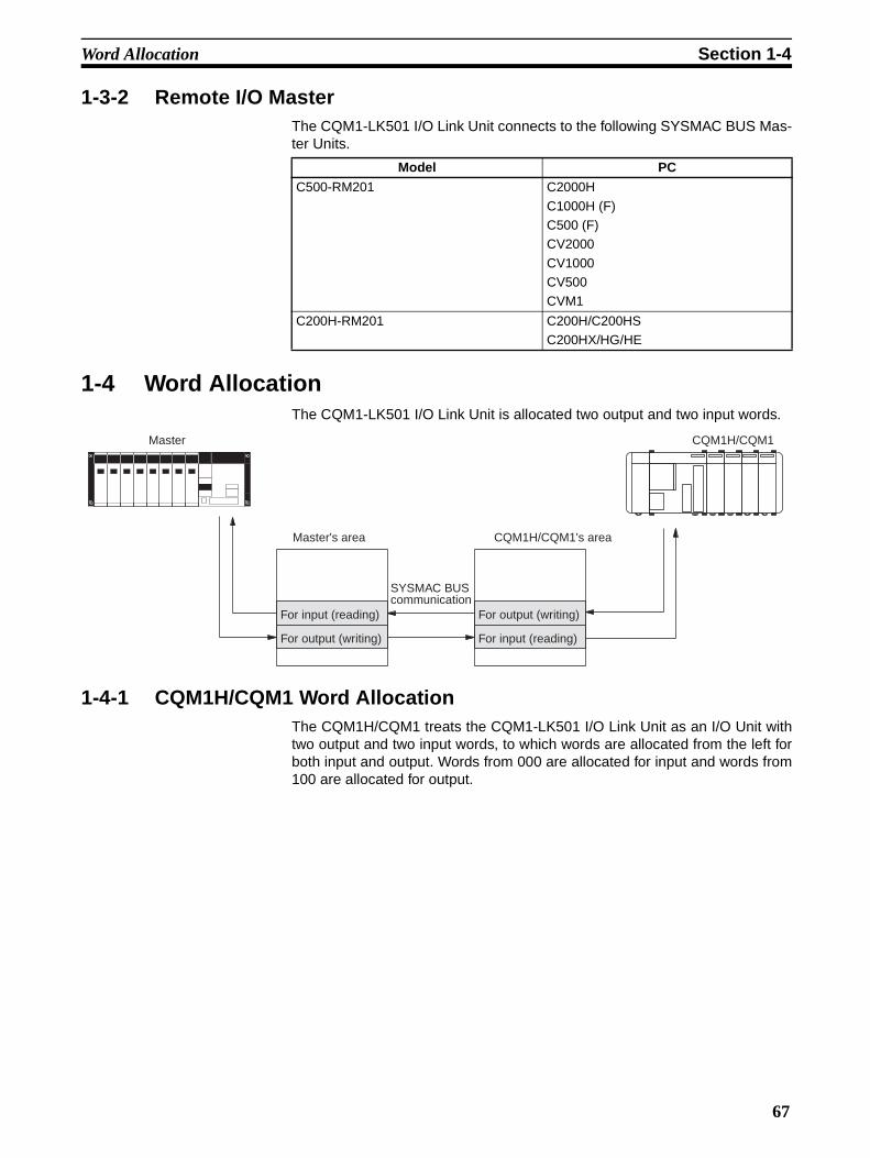
Word Allocation Section 1-4
1-3-2 Remote I/O MasterThe CQM1-LK501 I/O Link Unit connects to the following SYSMAC BUS Mas-ter Units.
1-4 Word AllocationThe CQM1-LK501 I/O Link Unit is allocated two output and two input words.
1-4-1 CQM1H/CQM1 Word AllocationThe CQM1H/CQM1 treats the CQM1-LK501 I/O Link Unit as an I/O Unit withtwo output and two input words, to which words are allocated from the left forboth input and output. Words from 000 are allocated for input and words from100 are allocated for output.
Model PC
C500-RM201 C2000H
C1000H (F)C500 (F)CV2000
CV1000CV500CVM1
C200H-RM201 C200H/C200HSC200HX/HG/HE
Master
Master's area
For input (reading)
For output (writing)
SYSMAC BUS communication
For input (reading)
For output (writing)
CQM1H/CQM1's area
CQM1H/CQM1
67

Word Allocation Section 1-4
1-4-2 Master Word AllocationThe Master treats the CQM1-LK501 I/O Link Unit as a SYSMAC BUS RemoteI/O Slave Unit. Words are allocated to the SYSMAC BUS area and specifiedby the Master in the same way as other SYSMAC BUS Remote I/O SlaveUnits. All words to be used in the SYSMAC BUS area are set using the DIPswitch of the CQM1-LK501 I/O Link Unit as shown in the following figure.
The first word of the Master’s SYSMAC BUS area varies with the model asseen in the following table.
Model SYSMAC BUS area first word
C200H/C200HSC200HX/HG/HE
Word 200
C500 (F) Word 0
C1000H (F)
C2000H
Word 32x (Master base number)
CV2000CV1000
CV500CVM1
Word 2300 + 32x (Master base number)
→
CQM1-LK501 I/O Link Unit's DIP switch
Example
First offset address 24
Master's SYSMAC BUS area
Offset address
24
23
22
Corresponds to each binary digitON = 1, OFF = 0
22 x 0 + 23 x 1 + 24 x 1 = 24
24
0
31
68

SECTION 2Nomenclature and Settings
This section provides the nomenclature and switch settings for the CQM1-LK501 I/O Link Unit.
2-1 Nomenclature . . . . . . . . . . . . . . . . . . . . . . . . . . . . . . . . . . . . . . . . . . . . . . . . . 70
2-2 Switch Settings . . . . . . . . . . . . . . . . . . . . . . . . . . . . . . . . . . . . . . . . . . . . . . . . 71
69

Nomenclature Section 2-1
2-1 Nomenclature
Indicators
The terminator setting switch and DIP switch are located under the terminalboard.
The ERR T/R indicator is lit only when there is an error is and will flash auto-matically when the transmission returns to normal.
Indicators (see table)
Transmission terminal 2
Transmission terminal 1
Operation output terminalsOperation output terminals must be short-cir-cuited if transmission is normal when the Master is in operating mode. These terminals are used to retrieve signals from the Master in operation.
Terminal screws: M3Note To satisfy the EC directives (low-voltage
directives), provide reinforced insulation or double insulation for the power supply.
(refer to 3-1 SYSMAC BUS Cable Connections.)
(refer to 3-1 SYSMAC BUS Cable Connections.)
Name Color Function
RDY Green Lit while the CQM1H/CQM1 is supplied with power.
RUN Green Lit when the Master is in operating mode.
ERR T/R
Red Lit when there is a transmission error. Flashes during normal trans-mission.
70
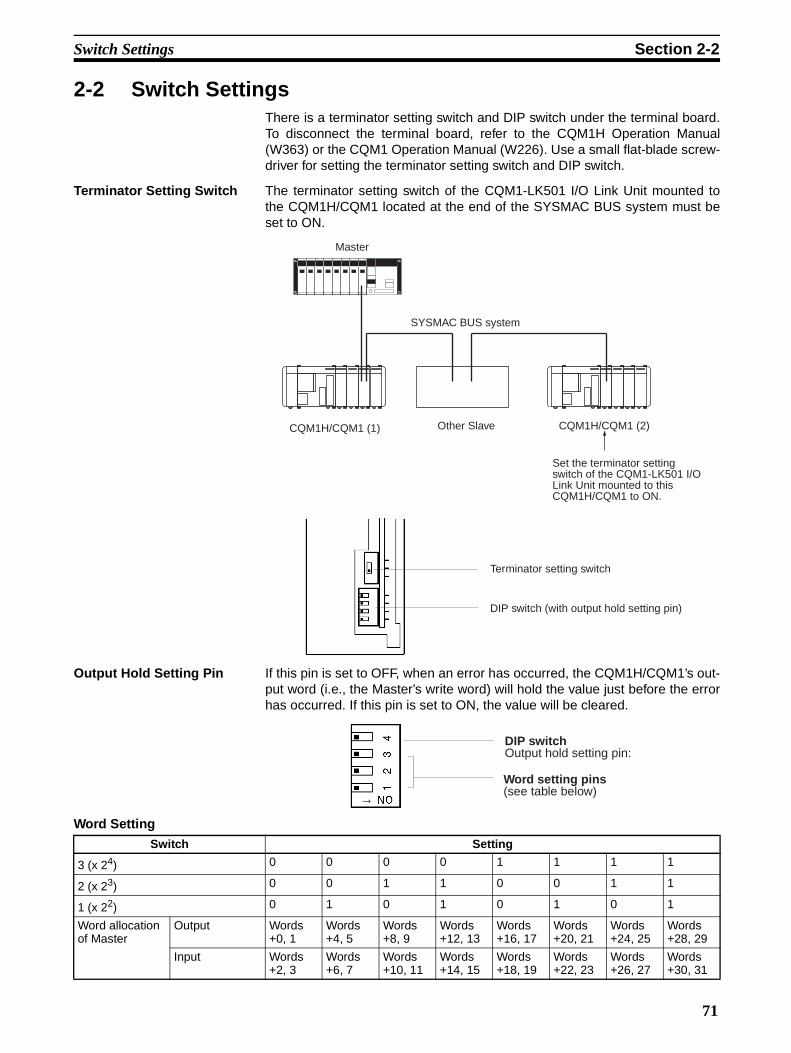
Switch Settings Section 2-2
2-2 Switch SettingsThere is a terminator setting switch and DIP switch under the terminal board.To disconnect the terminal board, refer to the CQM1H Operation Manual(W363) or the CQM1 Operation Manual (W226). Use a small flat-blade screw-driver for setting the terminator setting switch and DIP switch.
Terminator Setting Switch The terminator setting switch of the CQM1-LK501 I/O Link Unit mounted tothe CQM1H/CQM1 located at the end of the SYSMAC BUS system must beset to ON.
Output Hold Setting Pin If this pin is set to OFF, when an error has occurred, the CQM1H/CQM1’s out-put word (i.e., the Master’s write word) will hold the value just before the errorhas occurred. If this pin is set to ON, the value will be cleared.
Word Setting
Master
CQM1H/CQM1 (1) Other Slave
SYSMAC BUS system
CQM1H/CQM1 (2)
Set the terminator setting switch of the CQM1-LK501 I/O Link Unit mounted to this CQM1H/CQM1 to ON.
Terminator setting switch
DIP switch (with output hold setting pin)
→
DIP switchOutput hold setting pin:
Word setting pins(see table below)
Switch Setting
3 (x 24) 0 0 0 0 1 1 1 1
2 (x 23) 0 0 1 1 0 0 1 1
1 (x 22) 0 1 0 1 0 1 0 1
Word allocation of Master
Output Words +0, 1
Words +4, 5
Words +8, 9
Words +12, 13
Words +16, 17
Words +20, 21
Words +24, 25
Words +28, 29
Input Words +2, 3
Words +6, 7
Words +10, 11
Words +14, 15
Words +18, 19
Words +22, 23
Words +26, 27
Words +30, 31
71

Switch Settings Section 2-2
ExampleIf pins 1 and 2 are set to OFF and pin 3 is set to ON on the CQM1-LK501 I/OLink Unit, and the CQM1-LK501 I/O Link Unit is connected to the C200HRemote I/O Master, the following words will be allocated on the C200H.Output: words 216 and 217Input: words 218 and 219
72

SECTION 3Connections
This section describes the SYSMAC BUS cable connections for the CQM1-LK501 I/O Link Unit.
3-1 SYSMAC BUS Cable Connections . . . . . . . . . . . . . . . . . . . . . . . . . . . . . . . . 74
73

SYSMAC BUS Cable Connections Section 3-1
3-1 SYSMAC BUS Cable ConnectionsConnect VCTF 0.75 x 2 C SYSMAC BUS cables to the CQM1-LK501 I/O LInkUnit as shown in the following.
Note Nothing is connected to these terminals in the case of the terminator.
Connect the Master and Slaves as described in the following.The positive terminal of the Master must be connected to the positive terminalof the Slave and the negative terminal of the Master must be connected to thenegative terminal of the Slave, and between Slaves, the positive terminalsmust be connected together and the negative terminals must be connectedtogether as shown in the above diagram.The end Slave of the system must be the terminator of the system. Any otherSlave must not be the terminator.
Note 1. Connect the terminals with crimp-style terminals and M3 terminal screwsthat are also used for CQM1H/CQM1 I/O Units.
2. Terminals B0 and B2 are short-circuited internally. Terminals B1 and B3 arealso short-circuited internally.
3. Be sure to turn all the Slaves on before turning on the Master. Any Slaveturned on after the Master is turned on will not be recognized by the Mas-ter.
Connect the positive signal line from the Master.
Connect the negative signal line from the Master.
Connect the positive signal line to the next Slave (see note).
Connect the negative signal line to the next Slave (see note).
A0
A1
A2
A3
B0
B1
B2
B3
B4
Remote I/O Master CQM1-LK501 I/O LInk Unit
Other Slave
Terminator setting
+
–
+
–+
–
+ –
74

SYSMAC BUS Cable Connections Section 3-1
4. To satisfy the EC directives (low-voltage directives), provide reinforced in-sulation or double insulation for the power supply when RUN OUTPUT isused.
75


Appendix ASpecifications
Standard SpecificationsThe standard specifications of the CQM1-LK501 I/O Link Unit conform to those of the CQM1H/CQM1 PC.
SYSMAC BUS Standard Specifications
Performance Specifications
Item Specification
Transmission method Time-division multiplex cyclic
Communication method Two-wire semi-duplex
Transmission path 2-core cable (VCTF 0.75 x 2 C is recommended)
Interface RS-485
Transmission speed 187.5k bps
Transmission distance 200 m max.
Item Specification
Name I/O Link Unit
Model CQM1-LK501
Current consumption 150 mA at 5 VDC
I/O delay 8 ms/64 points
I/O points 64 points (32 input points and 32 output points)
External output Operating output: G6D, SPST-NO, 2 A max.
Diagnostic function • Transmission error check (BCC + inverted double transmission collation)
• CPU error monitor• Transmission path error check
Weight 220 g max.
Dimensions 32 x 110 x 107 (W x H x D)
77

Specifications Appendix A
DimensionsThese dimensions are the same for all G730 Interface Unit models.
(Unit: mm)
78

PART IVAnalog Input Unit and Analog Power Supply Units
CQM1-AD041CQM1-IPS01
CQM1-IPS02
79


SECTION 1Features and System Configuration
This section provides the features and system configuration relating to the Analog Input Unit and Analog Power SupplyUnits.
1-1 Features . . . . . . . . . . . . . . . . . . . . . . . . . . . . . . . . . . . . . . . . . . . . . . . . . . . . . . 82
1-1-1 Analog Input Unit . . . . . . . . . . . . . . . . . . . . . . . . . . . . . . . . . . . . . . . 82
1-1-2 Analog Power Supply Units . . . . . . . . . . . . . . . . . . . . . . . . . . . . . . . 82
1-2 System Configuration . . . . . . . . . . . . . . . . . . . . . . . . . . . . . . . . . . . . . . . . . . . 83
1-3 Connecting Devices . . . . . . . . . . . . . . . . . . . . . . . . . . . . . . . . . . . . . . . . . . . . 83
1-3-1 CPU. . . . . . . . . . . . . . . . . . . . . . . . . . . . . . . . . . . . . . . . . . . . . . . . . . 83
1-3-2 Analog Power Supply Units . . . . . . . . . . . . . . . . . . . . . . . . . . . . . . . 83
1-4 System Construction . . . . . . . . . . . . . . . . . . . . . . . . . . . . . . . . . . . . . . . . . . . . 84
1-4-1 Total Number of I/O Words . . . . . . . . . . . . . . . . . . . . . . . . . . . . . . . 84
1-4-2 Total Current Consumption . . . . . . . . . . . . . . . . . . . . . . . . . . . . . . . 84
81
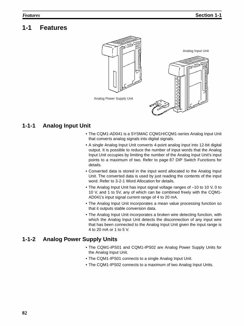
Features Section 1-1
1-1 Features
1-1-1 Analog Input Unit• The CQM1-AD041 is a SYSMAC CQM1H/CQM1-series Analog Input Unit
that converts analog signals into digital signals.
• A single Analog Input Unit converts 4-point analog input into 12-bit digitaloutput. It is possible to reduce the number of input words that the AnalogInput Unit occupies by limiting the number of the Analog Input Unit’s inputpoints to a maximum of two. Refer to page 87 DIP Switch Functions fordetails.
• Converted data is stored in the input word allocated to the Analog InputUnit. The converted data is used by just reading the contents of the inputword. Refer to 3-2-1 Word Allocation for details.
• The Analog Input Unit has input signal voltage ranges of –10 to 10 V, 0 to10 V, and 1 to 5V, any of which can be combined freely with the CQM1-AD041’s input signal current range of 4 to 20 mA.
• The Analog Input Unit incorporates a mean value processing function sothat it outputs stable conversion data.
• The Analog Input Unit incorporates a broken wire detecting function, withwhich the Analog Input Unit detects the disconnection of any input wirethat has been connected to the Analog Input Unit given the input range is4 to 20 mA or 1 to 5 V.
1-1-2 Analog Power Supply Units• The CQM1-IPS01 and CQM1-IPS02 are Analog Power Supply Units for
the Analog Input Unit.
• The CQM1-IPS01 connects to a single Analog Input Unit.
• The CQM1-IPS02 connects to a maximum of two Analog Input Units.
Analog Input Unit
Analog Power Supply Unit
82

System Configuration Section 1-2
1-2 System ConfigurationThe Analog Input Unit is mounted to the CQM1H/CQM1 CPU as shown in thefollowing illustration.
• The Analog Input Unit and Analog Power Supply Unit are mounted to theCPU, just like I/O Units.
• The Analog Input Unit can be mounted either on the left or right of theAnalog Power Supply Unit.
• Refer to 3-1 Settings for the wiring of the Analog Input Unit and AnalogPower Supply Unit.
Note Power must be supplied to the Analog Input Unit from the Analog Power Sup-ply Unit and CQM1H/CQM1, otherwise the Analog Input Unit will not operate.
1-3 Connecting Devices
1-3-1 CPUThe Analog Input Units can be mounted to the following CPUs.
1-3-2 Analog Power Supply UnitsPower can be supplied to the Analog Input Unit from the following AnalogPower Supply Units.
Power Supply Unit I/O UnitAnalog Power Supply Unit
Analog In-put Unit
I/O Unit
CPU
Sensors
Name Model
CQM1H-series CPU CQM1H-CPU11
CQM1H-CPU21
CQM1H-CPU51
CQM1H-CPU61
CQM1-series CPU CQM1-CPU11-ECQM1-CPU21-ECQM1-CPU41-EV1
CQM1-CPU42-EV1CQM1-CPU43-EV1CQM1-CPU44-EV1
Model Remarks
CQM1-IPS01 Connects to a single Analog Input Unit.
CQM1-IPS02 Connects to a maximum of two Analog input Units.
83

System Construction Section 1-4
1-4 System ConstructionThe Analog Input Unit occupies many words and consumes a large current.Therefore when constructing systems incorporating Analog Input Units, theuser should take the following into consideration.
1-4-1 Total Number of I/O WordsThe maximum number of available I/O words for each system varies with theCPU Unit. Refer to the following table.
The Analog Input Unit usually occupies four input words. On the other hand,the Analog Power Supply Unit does not use any I/O words. The total numberof words for each system must not exceed the above maximum number of I/Owords.
If the Analog Input Unit has one or two analog inputs, turn OFF pin 9 of theAnalog Input Unit’s DIP switch so that the Analog Input Unit will occupy onlytwo words.
1-4-2 Total Current ConsumptionThe following is the capacity of each available Power Supply Unit, from whichpower is supplied to a whole system.
The following table lists the current consumptions of the Analog Input Unit andAnalog Power Supply Units. Refer to the CQM1H Operation Manual (W363)or the CQM1 Operation Manual (W226) and select the most suitable PowerSupply Unit for your CQM1H/CQM1.
!Caution The total current consumption of each system must not exceed the capacity ofthe Power Supply Unit to be used.
Model Maximum number of I/O
words
CQM1H-CPU11 16
CQM1H-CPU21
CQM1H-CPU51 32
CQM1H-CPU61
CQM1-CPU11-ECQM1-CPU12-E
8
CQM1-CPU41-EV1
CQM1-CPU42-EV1CQM1-CPU43-EV1CQM1-CPU44-EV1
16
Model Capacity
CQM1-PA203 5 VDC, 3.6 A, 18 W
CQM1-PA206, CQM1-PA216
5 VDC, 6.0 A24 VDC output, 0.5 ATotal: 30 W
CQM1-PD026 5 VDC, 6 A, 30 W
Unit Unit Current consumption at 5 VDC
Analog Input Unit CQM1-AD041 80 mA
Analog Power Supply Unit
CQM1-IPS01 420 mA
CQM1-IPS02 950 mA
84

SECTION 2Nomenclature and Functions
This section provides the nomenclature and functions of the Analog Input Unit and Analog Power Supply Units.
2-1 Nomenclature . . . . . . . . . . . . . . . . . . . . . . . . . . . . . . . . . . . . . . . . . . . . . . . . . 86
2-1-1 Analog Input Unit . . . . . . . . . . . . . . . . . . . . . . . . . . . . . . . . . . . . . . . 86
2-1-2 Analog Power Supply Unit . . . . . . . . . . . . . . . . . . . . . . . . . . . . . . . . 88
2-2 Functions . . . . . . . . . . . . . . . . . . . . . . . . . . . . . . . . . . . . . . . . . . . . . . . . . . . . . 89
2-2-1 Analog Input Unit . . . . . . . . . . . . . . . . . . . . . . . . . . . . . . . . . . . . . . . 89
85

Nomenclature Section 2-1
2-1 Nomenclature
2-1-1 Analog Input Unit
Indicators
Terminals
Indicators
Input terminal 1
Input terminal 2
Input terminal 3
Input terminal 4
Protective ground terminal
Power supply cable
DIP switch
Left ViewFront View
CQM1-AD041
Terminal screws: M3
Name Color Function
RDY Green Lit while the CQM1H/CQM1 is turned on and the Analog Input Unit is operating normally.
ERR Red Lit when pins 1 to 8 of the DIP switch on the left side of the Analog Input Unit are all set to OFF (i.e., when the conver-sion of all inputs is prohibited).
BROKEN WIRE
Red Lit when an broken input wire is detected in an input range of 4 to 20 mA at 1 to 5 V.
2CH/4CH Orange Lit when there are four words occupied. Not lit when there are two words occupied.
Terminal Usage
Input terminal 1 Connect analog input for input 1.
Input terminal 2 Connect analog input for input 2.
Input terminal 3 Connect analog input for input 3.
Input terminal 4 Connect analog input for input 4.
Protective ground terminal Connect the shielded wire of the analog input cable.
86
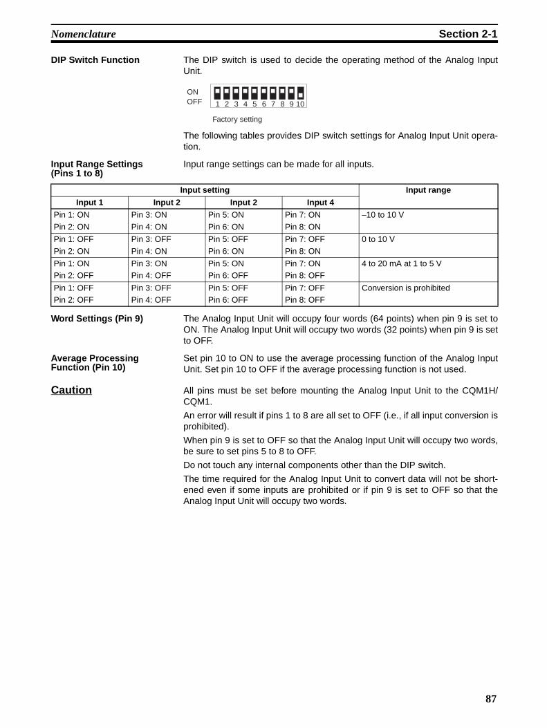
Nomenclature Section 2-1
DIP Switch Function The DIP switch is used to decide the operating method of the Analog InputUnit.
The following tables provides DIP switch settings for Analog Input Unit opera-tion.
Input Range Settings (Pins 1 to 8)
Input range settings can be made for all inputs.
Word Settings (Pin 9) The Analog Input Unit will occupy four words (64 points) when pin 9 is set toON. The Analog Input Unit will occupy two words (32 points) when pin 9 is setto OFF.
Average Processing Function (Pin 10)
Set pin 10 to ON to use the average processing function of the Analog InputUnit. Set pin 10 to OFF if the average processing function is not used.
Caution All pins must be set before mounting the Analog Input Unit to the CQM1H/CQM1.
An error will result if pins 1 to 8 are all set to OFF (i.e., if all input conversion isprohibited).
When pin 9 is set to OFF so that the Analog Input Unit will occupy two words,be sure to set pins 5 to 8 to OFF.
Do not touch any internal components other than the DIP switch.
The time required for the Analog Input Unit to convert data will not be short-ened even if some inputs are prohibited or if pin 9 is set to OFF so that theAnalog Input Unit will occupy two words.
1 3 4 5 6 7 82 9 10
Factory setting
ONOFF
Input setting Input range
Input 1 Input 2 Input 2 Input 4
Pin 1: ON
Pin 2: ON
Pin 3: ON
Pin 4: ON
Pin 5: ON
Pin 6: ON
Pin 7: ON
Pin 8: ON
–10 to 10 V
Pin 1: OFF
Pin 2: ON
Pin 3: OFF
Pin 4: ON
Pin 5: OFF
Pin 6: ON
Pin 7: OFF
Pin 8: ON
0 to 10 V
Pin 1: ONPin 2: OFF
Pin 3: ONPin 4: OFF
Pin 5: ONPin 6: OFF
Pin 7: ONPin 8: OFF
4 to 20 mA at 1 to 5 V
Pin 1: OFFPin 2: OFF
Pin 3: OFFPin 4: OFF
Pin 5: OFFPin 6: OFF
Pin 7: OFFPin 8: OFF
Conversion is prohibited
87

Nomenclature Section 2-1
2-1-2 Analog Power Supply Unit
Indicators
Note The P/S, P/S1, and P/S2 indicators are not lit when the power supply cable isdisconnected.
Cable Connections • Connect the power supply cable of the Analog Input Unit to the powersupply connector of the Analog Power Supply Unit and secure the powersupply cable connector with screws.
• The CQM1-IPS02 incorporates two power supply connectors. The powersupply cable of the Analog Input Unit can be connected to either one ofthe power supply connectors.
!Caution Be sure to turn off the Analog Power Supply Unit before connecting or discon-necting the power supply cable of the Analog Input Unit. After connecting thepower supply cable, secure the power supply cable with the lock screws.
Indicators
Connector for the power supply cable of the Analog Input Unit
CQM1-IPS01
Indicators
Connectors for the power supply cable of the Analog Input Unit
Connector 1 Connector 2
CQM1-IPS02
Name Color Function
P/S (incorporated by the CQM1-IPS01 only)
Green Lit when power is supplied to the Analog Input Unit via the CQM1-IPS01.
P/S1 (incorporated by the CQM1-IPS02 only)
Green Lit when power is supplied to the Analog Input Unit via Connector 1 of the CQM1-IPS02.
P/S2 (incorporated by the CQM1-IPS02 only)
Green Lit when power is supplied to the Analog Input Unit via Connector 2 of the CQM1-IPS02.
88
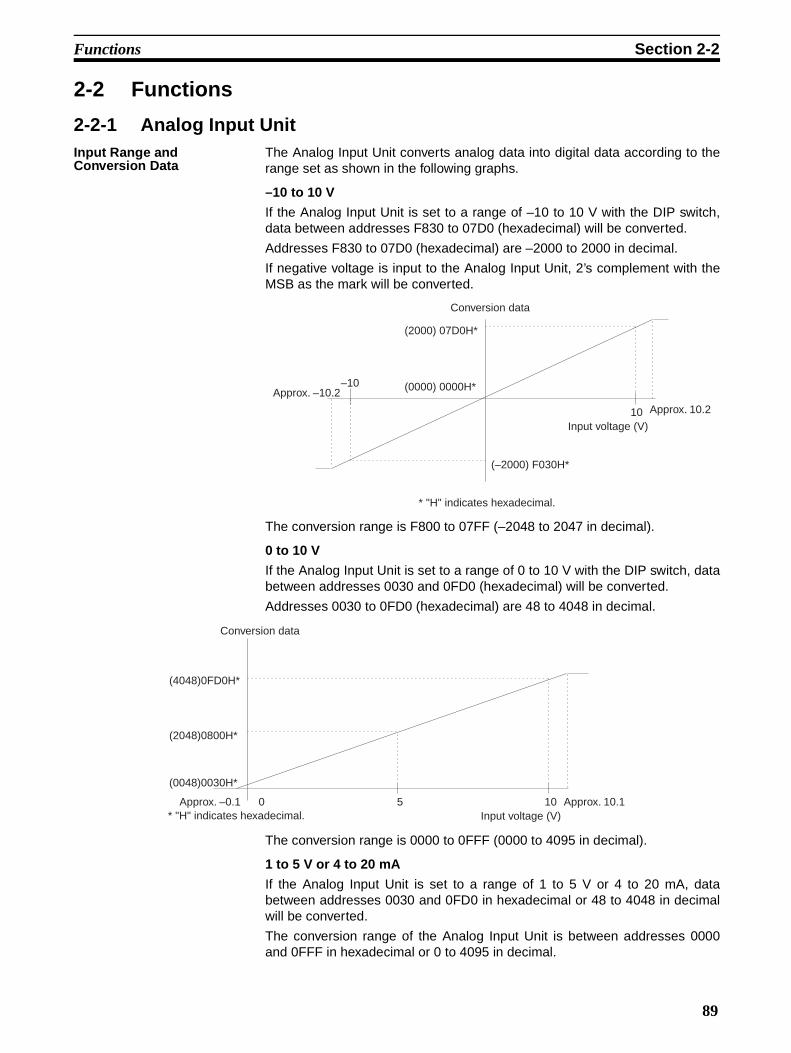
Functions Section 2-2
2-2 Functions
2-2-1 Analog Input UnitInput Range and Conversion Data
The Analog Input Unit converts analog data into digital data according to therange set as shown in the following graphs.
–10 to 10 V
If the Analog Input Unit is set to a range of –10 to 10 V with the DIP switch,data between addresses F830 to 07D0 (hexadecimal) will be converted.
Addresses F830 to 07D0 (hexadecimal) are –2000 to 2000 in decimal.
If negative voltage is input to the Analog Input Unit, 2’s complement with theMSB as the mark will be converted.
The conversion range is F800 to 07FF (–2048 to 2047 in decimal).
0 to 10 V
If the Analog Input Unit is set to a range of 0 to 10 V with the DIP switch, databetween addresses 0030 and 0FD0 (hexadecimal) will be converted.
Addresses 0030 to 0FD0 (hexadecimal) are 48 to 4048 in decimal.
The conversion range is 0000 to 0FFF (0000 to 4095 in decimal).
1 to 5 V or 4 to 20 mA
If the Analog Input Unit is set to a range of 1 to 5 V or 4 to 20 mA, databetween addresses 0030 and 0FD0 in hexadecimal or 48 to 4048 in decimalwill be converted.
The conversion range of the Analog Input Unit is between addresses 0000and 0FFF in hexadecimal or 0 to 4095 in decimal.
–10
10Input voltage (V)
Conversion data
(2000) 07D0H*
(0000) 0000H*
(–2000) F030H*
* "H" indicates hexadecimal.
Approx. –10.2
Approx. 10.2
0 10Input voltage (V)
5
Conversion data
* "H" indicates hexadecimal.
(4048)0FD0H*
(2048)0800H*
(0048)0030H*
Approx. –0.1 Approx. 10.1
89

Functions Section 2-2
If input data is below the converted range (i.e., the input voltage of the data isless than approximately 0.95 V or the input current of the data is less thanapproximately 3.8 mA), the broken wire detection function of the Analog InputUnit will be activated.
!Caution The Analog Input Unit converts inputs 1, 2, 3, 4, 1, etc., in this order. If theinput range is 1 to 5 V or 4 to 20 mA, the Analog Input Unit may be influencedby the previous input if the input has changed greatly. Avoid setting a range of–10 to 10 V as much as possible before using an input range of 1 to 5 V or 4to 20 mA.
Mean Value Processing Function
The mean value processing function of the Analog Input Unit is activated bysetting pin 10 of the Analog Input Unit’s DIP switch to ON. If the mean valueprocessing function is activated, all input values (inputs 1 to 4) will be aver-aged.
The mean value processing function enables the Analog Input Unit to converteach input value eight times, average the values, and store the results as dig-ital conversion data in the input word. The contents of the word are refreshedwith intervals of approximately 72 ms.
Note By using the AVG instruction of the CPU, only particular input values can beaveraged or the number of averaging operations can be changed.
Broken Wire Detecting Function• The broken wire detecting function of the Analog Input Unit makes it pos-
sible to detect and alarm the disconnection of any wire that has been con-nected to the Analog Input Unit.
• The broken wire detecting function of the Analog Input Unit will work whenthe input voltage and current drops to approximately 0.95 V and 3.8 mA orlower if the Analog Input Unit is set to a range of 1 to 5 V or 4 to 20 mA.
• When the Analog Input Unit detects wire disconnection, the broken wiredetecting indicator (BROKEN WIRE) will be lit and the broken wire flag ofthe input that has been disconnected will be set to 1. (Refer to 3-3-2Adjustment)
• The broken wire detecting indicator will reset to OFF automatically whenthe input returns to normal.
0
Input voltage (current)
1 V (4 mA) 3 V (12 mA) 5 V (20 mA)
Conversion data
* "H" indicates hexadecimal.
(4048) 0FD0H*
(4095) 0FFFH*
(2048) 0800H*
(0048) 0030H*(0000) 0000H*
Approx. 5.4 VApprox. 0.95 V
90

SECTION 3Operation
This section provides the operational procedures for the Analog Input Unit and Analog Power Supply Units.
3-1 Settings . . . . . . . . . . . . . . . . . . . . . . . . . . . . . . . . . . . . . . . . . . . . . . . . . . . . . . 92
3-1-1 Wiring . . . . . . . . . . . . . . . . . . . . . . . . . . . . . . . . . . . . . . . . . . . . . . . . 92
3-1-2 Wiring Precautions . . . . . . . . . . . . . . . . . . . . . . . . . . . . . . . . . . . . . . 92
3-2 Bit Number Allocation . . . . . . . . . . . . . . . . . . . . . . . . . . . . . . . . . . . . . . . . . . 94
3-2-1 Word Allocation . . . . . . . . . . . . . . . . . . . . . . . . . . . . . . . . . . . . . . . . 94
3-2-2 Bit Allocation . . . . . . . . . . . . . . . . . . . . . . . . . . . . . . . . . . . . . . . . . . 95
3-3 Programming and Adjustment . . . . . . . . . . . . . . . . . . . . . . . . . . . . . . . . . . . . 96
3-3-1 Programming . . . . . . . . . . . . . . . . . . . . . . . . . . . . . . . . . . . . . . . . . . 96
3-3-2 Adjustment . . . . . . . . . . . . . . . . . . . . . . . . . . . . . . . . . . . . . . . . . . . . 99
91

Settings Section 3-1
3-1 Settings
3-1-1 Wiring• Connect a two-conductor twisted-pair shielded cable to the Analog Input
Unit.
• The input terminals of the Analog Input Unit, to which the two-conductortwisted-pair shielded cable is connected, vary with the input range asshown in the following illustrations. In some environments, the shieldedwire of the two-conductor twisted-pair cable should be connected to theCOM terminal instead of the FG terminal of the Analog Input Unit so thatthe Analog Input Unit will not be influenced by external noise.
• The COM terminal is internally connected to the analog 0-V terminal ofthe Analog Input Unit.
Voltage Input
Current Input Short-circuit the V+ and I+ terminals for current input.
3-1-2 Wiring PrecautionsIn order to prevent noise interference, note the following when wiring the Ana-log Input Unit:
• Do not install power lines or high-tension lines along in close proximity tothe Analog Input Unit’s input lines.
• When connecting an inductive load such as a relay, solenoid, or electro-magnet valve to the Analog Input Unit, be sure to insert a surge absorp-tion diode or surge absorber to the load circuit as shown in the followingexamples. The surge absorption diode or surge absorber must be asclose as possible to the inductive load in the load circuit. The withstandvoltage of the surge absorption diode must be at least five times as largeas the circuit voltage.
V–I+
COM
FG
V+
FG
0 V
0 V
V–I+
COM
FG
V+
FG
92

Settings Section 3-1
DC Relay
AC Relay
Solenoid
If the Analog Input Unit malfunctions due to external noise through the powerline to the Analog Input Unit, insert a noise filter to the power line. The AnalogInput Unit may be influenced by noise if the Analog Input Unit and an electricwelding machine share a single power source or if the Analog Input Unit isoperated near a machine that generates high-frequency electromagneticwaves.
Use a twisted-pair cable for the input wiring to the Analog Input Unit.
RY Surge absorption diode (Fuji Den-ki's ERB44-06 or equivalent)DC
RY Surge absorber (Okaya Denki's CR-50500 or equivalent)AC
Surge absorber (Okaya Denki's CR-50500 or equivalent)
Solenoid
93

Bit Number Allocation Section 3-2
Following is the input circuit for the Analog Input Unit.
When the CQM1-IPS02 Analog Power Supply Unit is connected to the CQM1-AD021 Analog Input Unit and CQM1-DA021 Analog Output Unit, each analogground is connected.
3-2 Bit Number AllocationTwo input words or four input words can be allocated to the Analog Input Unit,which are specified with the DIP switch of the Analog Input Unit. Refer topage 87, DIP Switch Function for details.
3-2-1 Word AllocationInput words are allocated according to the mounting order (from left to right) ofthe Units. Refer to the CQM1H Programming Manual (W364), 3-2-3 I/O Allo-cation or the CQM1 Programming Manual (W228), 3-1 CQM1 Memory AreaFunctions for details on I/O word allocation.
1 MΩ
250 Ω
10 kΩ
1 MΩ
250 Ω
10 kΩ
1 MΩ250 Ω
10 kΩ
1 MΩ
250 Ω
10 kΩ
Analog ground
Inte
rnal
circ
uit
94

Bit Number Allocation Section 3-2
No word is allocated to the Analog Power Supply Unit. Mount the AnalogPower Supply Unit next to the Analog Input Unit either to the left or right.
3-2-2 Bit AllocationThe following shows how the words allocated to the Analog Input Unit areused. Any conversion data is stored in hexadecimal.
Error Flag (Bit 13 of the First Word)
Bit 13 of the first word functions as an error flag. The error flag turns ON(becomes 1) if an invalid setting is made with the DIP switch (e.g., prohibitingthe conversion of all words) and the Analog Input Unit does not operate. If theinput range of input 1 is –10 to 10 V and the conversion data of input 1 is neg-ative, however, this bit turns ON because 2’s complement is used to indicatethe negative data. If bit 15 of the first word is OFF and bit 13 is ON, it indicatesan error.
Broken Wire Detection Flag (Bit 12 of Each Word)
If the input range of the Analog Input Unit is 1 to 5 V or 4 to 20 mA and thevoltage of an input is less than approximately 0.95 V or the current of an inputis less than approximately 3.8 mA, the broken wire detecting function of theAnalog Input Unit will be activated and the bit 12 of the corresponding wordwill turn ON (the bit will become 1).
Example: Four words are occupied.Words 002 to 005 are used.
Word
CPU
000001
006100
IN 1
6 po
ints
Sensor
Sensor
Sensor
Sensor
(Input 1)
(Input 2)
(Input 3)
(Input 4)
CQM1H/CQM1
IN 1
6 po
ints
IN 1
6 po
ints
Out
16
poin
tsPS
AD
IPS
PS : Power Supply UnitCPU : CPUIN : Input Unit and terminalsOUT : Output UnitIPS : Analog Power Supply UnitAD : Analog Input Unit
BitWord
15 14 13 12 11 10 09 08 07 06 05 04 03 02 01 00
n Input 1 conversion data
n + 1 Input 2 conversion data
n + 2 Input 3 conversion data
n + 3 Input 4 conversion data
95

Programming and Adjustment Section 3-3
3-3 Programming and Adjustment
3-3-1 ProgrammingThis section provides program examples for the Analog Input Unit using fourwords in the following input ranges. The program examples are not valid forthe Analog Input Unit with its mean value processing function activated.
Refer to the SYSMAC CQM1H/CQM1 Programming Manual for details on theinstructions that are used.
Power ON It takes approximately 10 ms for the Analog Input Unit to store the first conver-sion data after the Analog Input Unit is turned on if the mean value processingfunction of the Analog Input Unit is not activated. It takes approximately 72 msfor the Analog Input Unit to store the first conversion data after the AnalogInput Unit is turned on if the mean value processing function is activated. If theuser wants to operate the Analog Input Unit immediately after turning the Ana-log Input Unit on, construct the following program so that the Analog Input Unitwill wait until the conversion data becomes effective.
When the power is ON, Timer 5 starts operating. The Up Flag of Timer 5 turnsON 100 ms later and the conversion data of input 1, which is stored in word002, will be transferred to DM 0000.
Scaling The conversion of input voltage or current in a certain range to a value in acertain range is called scaling. For example, if the user converts input voltageor current so to be displayed as a percentage, the converted value will be dis-played in the range 0 through 100.
Use the CPU instructions SCL and SCL2 for scaling.
Note The SCL2 instruction cannot be used on the CQM1-CPU11-E or CQM1-CPU21-E.
An example for the conversion of negative data in an input range of –10 to10 V into a positive value is provided.
Input Input range Word storing conversion data
Input 1 0 to 10 V Wd 002
Input 2 4 to 20 mA Wd 003
Input 3 1 to 5 V Wd 004
Input 4 –10 to 10 V Wd 005
MOV(21)
* n
DM 0000
* "n" indicates the allocated word for analog input.
TIM
n
#C0001
T005
25313 (Always ON)
96

Programming and Adjustment Section 3-3
SCLThe following is an example of SCL instruction use.
When input 00000 turns ON, the conversion data of Word 002 is scaledaccording to the parameters set in DM 0100 and DM 0102 and the result isstored in DM 0000.
Scaling is executed so that 0030 to 0FD0 (hexadecimal) will correspond to0000 to 0100 (BCD).
SCL2The following is an example of SCL2 instruction use.
When input 00000 turns ON, the conversion data of Word 002 is scaledaccording to the parameters set in DM 0100 to DM 0102 and the result isstored in DM 0000.
Scaling is executed by subtracting 30 (hexadecimal) from the conversion dataand multiplying the result by 1/40 (0001 (BCD)/0028 (hexadecimal)) so that0030 to 0FD0 (hexadecimal) will correspond to 0 to 100 (BCD).
Program Example for Scaling Conversion Data in an Input Range of –10 to 10 V into a Positive Value
The SCL2 instruction processes negative values expressed by 2’s comple-ment. On the other hand, the SCL instruction cannot process negative values.The following is an example of the scaling of negative conversion data in aninput range of –10 to 10 V into a positive value so that the positive value canbe processed by the SCL instruction.
When input 00000 turns ON, the rightmost 12 bits of the conversion data inWord 005 is obtained by the ANDW instruction and stored in DM 0200 asseen in the following program.
* " n" indicates the allocated word for analog input.
SCL(66)
* n
DM 0100
DM 0000
00000
DM 0100 0000 (BCD)DM 0101 0030 (Hexadecimal)DM 0102 0100 (BCD)DM 0103 0FD0 (Hexadecimal)
Set value
* "n" indicates the allocated word for analog input.
SCL2( )
* n
DM 0100
DM 0000
00000
DM 0100 0030 (Hexadecimal)DM 0101 0028 (Hexadecimal)DM 0102 0001 (BCD)
Set value
97

Programming and Adjustment Section 3-3
The XORW instruction is used to reverse Bit 12 of the stored value so that therange of the value will be shifted.
Scaling is executed so that F830 to 07D0 (hexadecimal) will correspond to0030 to 0FD0 (hexadecimal).
Use the SCL and SCL2 instructions to convert the range further.
Mean Value Processing Mean value processing is used to convert unstable input or shut out noiseinterference. Either the mean value processing function of the Analog InputUnit or the AVG instruction can be used.
In this section, mean value processing using the AVG instruction is explained.Refer to 2-2 Functions for details on the mean value processing function ofthe Analog Input Unit.
The AVG instruction makes it possible to average conversion data the numberof times specified by the user per scan.
!Caution The AVG instruction cannot handle 2’s complement. If the conversion data is2’s complement (i.e., the Analog Input Unit is set to a range of –10 to 10 V),use the AVG instruction with the following program.
When input 00000 turns ON, any conversion data (F830 to 07D0) in a rangeof –10 to 10 V is converted into a positive value (0030 to 0FD0) by the ANDWand XORW instructions. Then the mean value of the converted data isobtained by the AVG instruction. Ten data values in BCD are stored in DM0300 to obtain the mean value of the converted data. The mean value isstored in DM 0000.
While input 00000 is ON, the mean value of the latest 10 data values isalways stored in DM 0000.
When the AVG instruction is used, the number of words equal to the numberof data values to obtain the mean value plus two words must be secured next
* "n" indicates the allocated word for analog input.
ANDW(34)
#0FFF
n
DM 0200
XORW(36)
#0800
DM 0200
DM 0200
00000
07D0 (2000)to
0000 (0000)
07D0 (2000)to
0000 (0000)
0FFF (–0001)to
0830 (–2000)
0FD0 (4048)to
0800 (2048)
07FF (2047)to
0030 (0048)
1. ANDW instruction
Hexadecimal (decimal) Hexadecimal (decimal) Hexadecimal (decimal)
2. XORW instruction
FFFF (–0001)to
F830 (–2000)
98

Programming and Adjustment Section 3-3
to the word that stores the result. DM 0000 to DM 0011 are secured in theexample program.
3-3-2 AdjustmentThe accuracy of the Analog Input Unit is ±1% without adjustment. If this isadequate, the user need not adjust the Analog Input Unit. Fine tuning of theAnalog Input Unit is explained in this section.
The Analog Input Unit is adjusted with parameters set with the SCL instruc-tion.
0 to 10 V, 1 to 5 V, or 4 to 20 mA
If the Analog Input Unit is set to a range of 0 to 10 V, 1 to 5 V or 4 to 20 mA,follow the steps described below to adjust the Analog Input Unit.
1,2,3... 1. Refer to 3-1 Settings and connect the Analog Input Unit, CPU, and sensoror transducer.
2. Connect a peripheral device such as a Programming Console to the CPU(in any mode) and monitor the allocated word of the analog input to be ad-justed.
3. Obtain the minimum value of the sensing object. For a sensing operation,for example, set the sensing object so that the output value of the sensoror transducer will be minimum. For temperature measurement, it may bedifficult to obtain the minimum value. In that case, instead of using the sen-sor or transducer, use a reference power supply to obtain the output at thelowest temperature.
* "n" indicates the allocated word for analog input.
Input condition
ANDW(34)
#0FFF
n
DM 0200
XORW(36)
#0800
DM 0200
DM 0200
AVG( )
DM 0200
#0300
DM 0000
PS CPU OUT AD OUTIN
ADIPS
Sensor or transducerSensing object
Peripheral device
99

Programming and Adjustment Section 3-3
4. Use the peripheral device to monitor the word to which the analog inputdata to be adjusted is stored. The CQM1H/CQM1 can be in any mode. Theanalog input conversion data will be the lower-limit value.
5. Apply the same method to the analog input’s maximum value to obtain theupper-limit value.
6. Create the following program to scale values in a range between the lowerand upper-limit values and designate the lower- and upper-limit values thathave been monitored as parameters. Refer to page 96, Scaling for details.
–10 to 10 V If the Analog Input Unit is set to a range of –10 to 10 V, follow the stepsdescribed below to adjust the Analog Input Unit.
1,2,3... 1. Refer to 3-1 Settings and connect the Analog Input Unit, CPU, and sensoror transducer.
2. Connect a peripheral device such as a Programming Console to the CPUand while referring to 3-3-1 Programming, create a program to convert 2’scomplement.
* "n" indicates the allocated word for analog input.
SCL(66)
* n
DM 0100
DM 0000
00000
DM 0100DM 0101DM 0102DM 0103
0000
0100
Set value
(BCD)(Hexadecimal) Lower limit value(BCD)(Hexadecimal) Upper limit value
PS CPU OUT AD OUTIN
ADIPS
Sensor or transducerSensing object
Peripheral device
* "n" indicates the allocated word for analog input.
Input condition
ANDW(34)
#0FFF
n
DM 0200
XORW(36)
#0800
DM 0200
DM 0200
00000
100

Programming and Adjustment Section 3-3
3. Obtain the minimum value of the sensing object. For a sensing operation,for example, set the sensing object so that the output value of the sensoror transducer will be minimum. For temperature measurement, it may bedifficult to obtain the minimum value. In that case, instead of using the sen-sor or transducer, use a reference power supply to obtain the output at thelowest temperature.
4. Put the CQM1H/CQM1 into operation mode or monitor mode and use theperipheral device to monitor the word (DM0200) in which the scaled con-version data is stored. The conversion data will be the lower-limit value.
5. Apply the same method to the analog input maximum value to obtain theupper-limit value.
6. Create the following program to scale values in a range between the lower-and upper-limit values and designate the lower and upper limit values thathas been monitored as parameters. Refer to page 96, Scaling for details.
* "n" indicates the allocated word for analog input.
ANDW(34)
#0FFF
n
DM 0200
XORW(36)
#0800
DM 0200
DM 0200
SCL(66)
DM 0200
DM 0100
DM 0000
00000
DM 0101DM 0100 0000 Insert the conversion value corresponding to the minimum value.
Insert the monitor value "lower limit value."DM 0102 0100 Insert the conversion value corresponding to the maximum value.DM 0103 Insert the monitor value "upper limit value."
Set value
101


Appendix ASpecifications
Standard SpecificationsThe standard specifications of the Analog Input Unit and Analog Power Supply Units conform to those of theCQM1H/CQM1 PC.
Performance Specifications
CQM1-AD041 Analog Input Unit
Note 1. Conversion data is refreshed every 10 ms (2.5 ms x 4).
2. Analog input terminals are not insulated from one another.
Item Specification
Input signal range Voltage input –10 to 10 V
0 to 10 V
1 to 5 V
Current input 4 to 20 mA
External input impedance Voltage input 1 MΩ max.
Current input 250 ΩResolution 1/4000
Accuracy ±0.5% (25°C)±1.0% (0° to 55°C)
Conversion speed 2.5 ms/point (see note 1)
Maximum input signal Voltage input ±15 V max.
Current input ±30 mA max.
Insulation method Input terminals and PC signals are insulated with photocoupler (see note 2)
Current consumption 80 mA at 5 VDC excluding the current supplied from the Analog Power Supply Unit.
Weight 210 g
Dimensions 32 x 110 x 107 (W x H x D) mm
103
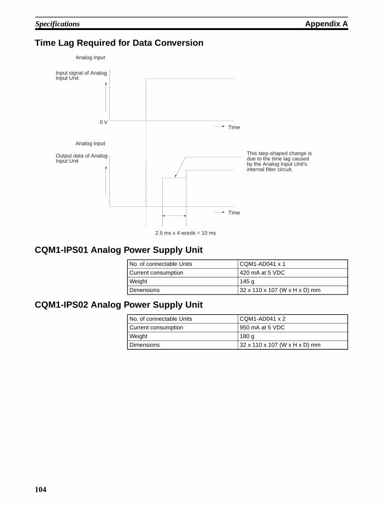
Specifications Appendix A
Time Lag Required for Data Conversion
CQM1-IPS01 Analog Power Supply Unit
CQM1-IPS02 Analog Power Supply Unit
Analog input
Input signal of Analog Input Unit
Analog input
Output data of Analog Input Unit
Time
Time
This step-shaped change is due to the time lag caused by the Analog Input Unit's internal filter circuit.
2.5 ms x 4 words = 10 ms
0 V
No. of connectable Units CQM1-AD041 x 1
Current consumption 420 mA at 5 VDC
Weight 145 g
Dimensions 32 x 110 x 107 (W x H x D) mm
No. of connectable Units CQM1-AD041 x 2
Current consumption 950 mA at 5 VDC
Weight 180 g
Dimensions 32 x 110 x 107 (W x H x D) mm
104

Specifications Appendix A
Dimensions
Analog Input Unit
Analog Power Supply Unit
10713047 284
110
32
115.7
2
122
107
Approx. 14032
115.7
2
110
105

Specifications Appendix A
106

Appendix BTroubleshooting
Analog Input Unit
Analog Power Supply Unit
Kind of error Phenomenon Cause Remedy
Indicator The RDY indicator is not lit. 1. The Unit is not connected properly.
2. No end cover is attached.
Refer to the CQM1H/CQM1 Operation Manual and reset the Analog Input Unit.
The ERR indicator is lit. The DIP switch is set to prohibit the conversion of all inputs.
Refer to 2-1 Nomenclature and set the DIP switch properly.
The BROKEN WIRE indicator is lit.
An input set to a range of 1 to 5 V or 4 to 20 mA is disconnected.
Check the wiring, terminal board, input voltage, and input current.
Unused analog input is set to a range of 1 to 5 V or 4 to 20 mA.
Set the unused analog input to any other range or set to prohibit conversion.
No. of words The Analog Input Unit can be allocated to two words only or allocated to four words.
The DIP switch setting is incor-rect.
The DIP switch setting can be monitored with the 2 CH and 4 CH indicators. Check whether the setting is proper. If not, set the DIP switch properly.
Conversion data The conversion data of the Ana-log Input Unit does not change even if the input voltage or cur-rent is changed.
The power cable is not con-nected to the Analog Power Supply Unit.
Connect the power cable.
The voltage or current input is not within the range that has been set.
Check the input voltage or cur-rent or the range that has been set.
The conversion data of the Ana-log Input Unit changes slowly when the input voltage or current is changed.
The mean value processing function is working.
Set the mean value processing switch properly.
I/O Unit over The CPU has an I/O Unit over error.
The total number words used by the Units connected exceed the maximum available words of the CPU.
Each Analog Input Unit uses four or two words. Check if the total number of words are exceeding the maximum avail-able words of the CPU.
Kind of error Phenomenon Cause Remedy
LED The P/S (P/S1, P/S2) indicator is not lit.
The power supply cable of the Analog Input Unit is not con-nected to the Analog Power Supply Unit.
Connect the power supply cable to the Analog Power Supply Unit. Turning on the Analog Power Supply Unit will not cause the P/S (P/S1, P/S2) indicator to be lit if the power supply cable of the Analog Input Unit is not con-nected to the Analog Power Supply Unit.
Power is not supplied to the sys-tem.
Supply power to the system.
107


PART VAnalog Output Unit and Analog Power Supply Units
CQM1-DA021CQM1-IPS01
CQM1-IPS02
109


SECTION 1Features and System Configuration
This section provides the features and system configuration relating to the Analog Output Unit and Analog Power SupplyUnits.
1-1 Features of Analog Output Unit . . . . . . . . . . . . . . . . . . . . . . . . . . . . . . . . . . . 112
1-2 System Configuration . . . . . . . . . . . . . . . . . . . . . . . . . . . . . . . . . . . . . . . . . . . 112
1-2-1 Analog Power Supply Units . . . . . . . . . . . . . . . . . . . . . . . . . . . . . . . 113
1-2-2 CPU. . . . . . . . . . . . . . . . . . . . . . . . . . . . . . . . . . . . . . . . . . . . . . . . . . 113
111

Features of Analog Output Unit Section 1-1
1-1 Features of Analog Output Unit
• The CQM1-DA021 is a SYSMAC CQM1H/CQM1-series Analog OutputUnit that converts digital signals into analog signals.
• The Analog Output Unit has an output signal current range of 0 to 20 mAand an output signal voltage range of –10 to 10V.
• A single Analog Output Unit allows two-point digital-to-analog conversion.
• It takes only 0.5 ms for two-point digital-to-analog conversion.
1-2 System ConfigurationThe Analog Output Unit is mounted to the CQM1H/CQM1 CPU as shown inthe following illustration.
• The CQM1-IPS01 Analog Power Supply Unit connects to a single AnalogOutput Unit.
• A single Analog Input Unit and single Analog Output Unit can be con-nected to the CQM1-IPS02 Analog Power Supply Unit. Two Analog Out-put Units cannot be connected to the CQM1-IPS02 Analog Power SupplyUnit.
• The Analog Output Unit and Analog Power Supply Unit are mounted tothe CPU, just like I/O Units.
• The Analog Output Unit can be mounted either on the left or right of theAnalog Power Supply Unit. The Analog Output Unit must be, however,adjacent to the Analog Power Supply Unit.
• Refer to 3-1 Settings for the wiring of the Analog Output Unit and AnalogPower Supply Unit.
Power Supply Unit I/O Unit I/O Unit
CPU
Controllers
112

System Configuration Section 1-2
Note Power must be supplied to the Analog Output Unit from the Analog PowerSupply Unit and CQM1H/CQM1, otherwise the Analog Output Unit will notoperate.
1-2-1 Analog Power Supply UnitsThe following table lists the current consumptions of the Analog Output Unitand Analog Power Supply Units. To select the Analog Power Supply Unit, referto the CQM1H Operation Manual (W363) or the CQM1 Operation Manual(W226) for details.
1-2-2 CPUThe Analog Output Unit occupies two I/O words. Make sure that the total I/Opoints will not exceed the I/O points of the CPU. The Power Supply Unit doesnot occupy any words.
Unit Current consumption at 5 VDC (mA)
CQM1-DA021 90 mA
CQM1-IPS01 420 mA
CQM1-IPS02 950 mA
113


SECTION 2Nomenclature and Functions
This section provides the nomenclature and functions of the Analog Output Unit.
2-1 Nomenclature . . . . . . . . . . . . . . . . . . . . . . . . . . . . . . . . . . . . . . . . . . . . . . . . . 116
2-1-1 Functions of Setting Pins . . . . . . . . . . . . . . . . . . . . . . . . . . . . . . . . . 117
2-2 Functions . . . . . . . . . . . . . . . . . . . . . . . . . . . . . . . . . . . . . . . . . . . . . . . . . . . . . 117
2-2-1 Output Characteristics . . . . . . . . . . . . . . . . . . . . . . . . . . . . . . . . . . . 117
115

Nomenclature Section 2-1
2-1 NomenclatureFront View
Left Side View
Indicator
Terminal screws: M3
I1+
I1
V1+
V1
I2+
I2
V2+
V2
DA021
Indicator
Output terminal 1
Output terminal 2
Power supply cable(Connect to Analog Power Supply Unit)
Indicator
JT1 setting pin
JT2 setting pin
Power supply cable
The green indicator of the Unit will be lit if the Unit starts normally.
116

Functions Section 2-2
Terminals
2-1-1 Functions of Setting PinsThe setting pins are used to prohibit negative voltage output.
When negative voltage output is prohibited, 0 V is output from the voltage out-put terminal if the Analog Output Unit has negative voltage output data.
Note 1. At the time of program debugging with an external device connected to theAnalog Output Unit, set the setting pins to prohibit negative voltage outputso that the wrong output will not damage the external device. Do not usethe Analog Output Unit to output negative voltage while the setting pins areset to prohibit negative voltage output.
2. If an input circuit incorporating a pull-up resistor is connected to the AnalogOutput Unit, set the setting pins to normal setting. If the setting pins are setto prohibit negative voltage output, the Analog Output Unit will be influ-enced by the synch current and no output will be ON properly.
3. Do not touch any internal components other than the setting pins.
2-2 Functions
2-2-1 Output CharacteristicsThe Analog Output Unit converts data from the CPU into voltage or currentand outputs the data to the voltage terminal or current terminal.
Voltage Output Data between 0000 and 07FF (hexadecimal) for output from the CPU are con-verted into a voltage of 0 to 10 V and output.
Negative voltage is converted to 2’s complement with the MSB. Data betweenF800 to FFFF (hexadecimal) for output from the CPU is converted into a volt-age of –10 to 0V and output. If negative voltage output is prohibited, 0 V willbe output.
Bits 11 to 14 of output data have nothing to do with output voltage. For exam-ple, 0 V is output for 0000 and 7800 (hexadecimal).
Terminal Usage
Output terminal 1 Connect analog output for output 1.
Output terminal 2 Connect analog output for output 2.
Setting pin Status
JT1 Word n: Normal setting (factory set)
Word n: Negative voltage output prohibited
JT2 Word n + 1: Normal setting (factory set)
Word n + 1: Negative voltage output prohibited
Left Right
1 2 3
Left Right
1 2 3
15 10 9 8 7 6 5 4 3 2 1 0
MSB LSB
These four bits have nothing to do with the output voltage.MSB: Most significant bit
LSB: Least significant bit
117
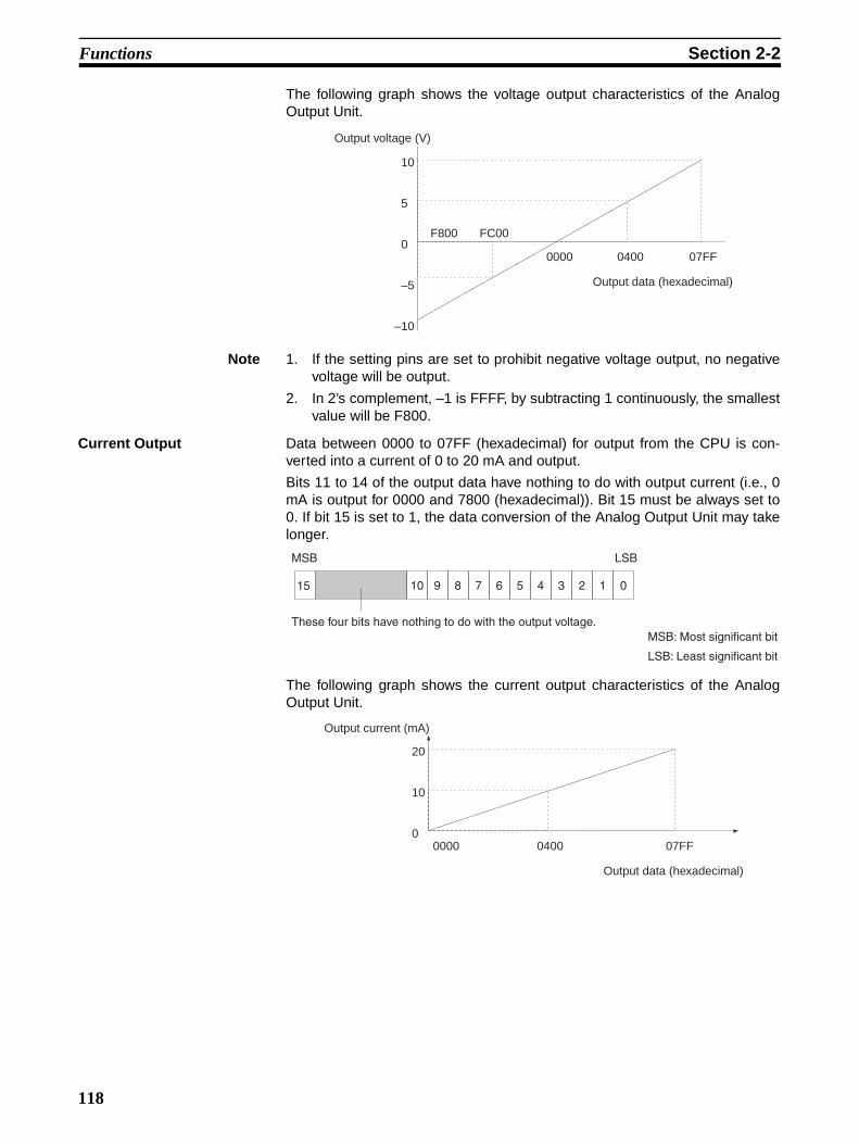
Functions Section 2-2
The following graph shows the voltage output characteristics of the AnalogOutput Unit.
Note 1. If the setting pins are set to prohibit negative voltage output, no negativevoltage will be output.
2. In 2’s complement, –1 is FFFF, by subtracting 1 continuously, the smallestvalue will be F800.
Current Output Data between 0000 to 07FF (hexadecimal) for output from the CPU is con-verted into a current of 0 to 20 mA and output.
Bits 11 to 14 of the output data have nothing to do with output current (i.e., 0mA is output for 0000 and 7800 (hexadecimal)). Bit 15 must be always set to0. If bit 15 is set to 1, the data conversion of the Analog Output Unit may takelonger.
The following graph shows the current output characteristics of the AnalogOutput Unit.
Output voltage (V)
10
5
0
–5
–10
F800 FC00
Output data (hexadecimal)
0000 0400 07FF
15 10 9 8 7 6 5 4 3 2 1 0
MSB LSB
These four bits have nothing to do with the output voltage.MSB: Most significant bit
LSB: Least significant bit
Output current (mA)
20
10
0
Output data (hexadecimal)
0000 0400 07FF
118

SECTION 3Operation
This section provides the operational procedures for the Analog Output Unit.
3-1 Settings . . . . . . . . . . . . . . . . . . . . . . . . . . . . . . . . . . . . . . . . . . . . . . . . . . . . . . 120
3-1-1 Cable Connections . . . . . . . . . . . . . . . . . . . . . . . . . . . . . . . . . . . . . . 120
3-1-2 Wiring . . . . . . . . . . . . . . . . . . . . . . . . . . . . . . . . . . . . . . . . . . . . . . . . 120
3-1-3 Terminal Arrangement . . . . . . . . . . . . . . . . . . . . . . . . . . . . . . . . . . . 122
3-2 Bit Number Allocation . . . . . . . . . . . . . . . . . . . . . . . . . . . . . . . . . . . . . . . . . . 122
3-2-1 Word Allocation . . . . . . . . . . . . . . . . . . . . . . . . . . . . . . . . . . . . . . . . 122
3-2-2 Bit Allocation . . . . . . . . . . . . . . . . . . . . . . . . . . . . . . . . . . . . . . . . . . 123
3-3 Programming and Adjustment . . . . . . . . . . . . . . . . . . . . . . . . . . . . . . . . . . . . 123
3-3-1 Programming . . . . . . . . . . . . . . . . . . . . . . . . . . . . . . . . . . . . . . . . . . 123
3-3-2 Precaution . . . . . . . . . . . . . . . . . . . . . . . . . . . . . . . . . . . . . . . . . . . . . 126
119

Settings Section 3-1
3-1 Settings
3-1-1 Cable Connections
• Connect the power supply cable of the Analog Output Unit to the powersupply connector of the Analog Power Supply Unit and secure the powersupply cable connector with screws.
• The CQM1-IPS02 incorporates two power supply connectors. The powersupply cable of the Analog Output Unit can be connected to either one ofthe power supply connectors.
• Refer to the CQM1H Operation Manual (W363) or the CQM1 OperationManual (W226) for details on connecting an Analog Output Unit and Ana-log Power Supply Unit.
Note Do not pull the power supply cable, or the power supply cable may be brokenor connector may be disconnected.
3-1-2 WiringVoltage Output
Current Output
Analog Output Unit Terminals
Analog Output Unit Terminals
120

Settings Section 3-1
• Connect a two-conductor twisted-pair shielded cable to the Analog OutputUnit.
• Do not install power lines or high-tension lines along in close proximity tothe Analog Output Unit’s output lines.
• The shielded wire must be grounded on the signal reception side.
• The negative side of each output lines are internally connected as shownin the following diagram.
If the CQM1-IPS02 is connected to the Analog Output Unit and Analog InputUnit, the analog GND terminal of the Analog Output Unit and that of the Ana-log Input Unit will be connected to each other.
Analog GND
I1+
I1–
V1+
V1–
I2+
I2–
V2+
V2–
121

Bit Number Allocation Section 3-2
3-1-3 Terminal Arrangement
3-2 Bit Number Allocation
3-2-1 Word AllocationOutput words are allocated according to the mounting order (from left to right)of the Units. Consecutive two output words are allocated to the Analog OutputUnit.
Indicators
Input terminal 1
Input terminal 2
Input terminal 3
Input terminal 4
Protective ground terminal
Power supply cable
Terminal screws: M3
Word 000Word 001
Word 100Word 101Word 102Word 103Word 104
122

Programming and Adjustment Section 3-3
3-2-2 Bit Allocation
Note The shaded parts do not have any influence on the output voltage (current) ofthe Analog Output Unit. All data is output in binary. Use a program to convertthe data from BCD.
3-3 Programming and Adjustment
3-3-1 ProgrammingData is output to the words that have been allocated to the Output Unit. Forexample, to output DM data, use the MOV (21) instruction as shown in the fol-lowing ladder diagram.
Scaling The conversion of a value in a certain range to an output voltage or current ina certain range is called scaling.
An example for the conversion of data using the SCL3 and APR instructions isprovided below. The SCL3 instruction cannot be used with the CQM1-CPU11or CQM1-CPU21.
By using the SCL3 and APR instructions, output data conversion from thePC’s data and data output can be performed simultaneously.
SCL3 Instruction The following is a program example for BCD output data stored in DM 0000.
Bit
Word15 14 13 12 11 10 09 08 07 06 05 04 03 02 01 00
n
n + 1
Output 1 Output data
Output 2 Output data
* "n" indicates the allocated word for analog output 1.
MOV(21)
DM0000
n
Input condition
* "n" indicates the allocated word for analog output 1.
CLC(41)
SCL3
DM 0000
DM 0100
n
Input condition
123

Programming and Adjustment Section 3-3
If the following DM settings are made, the scaling as shown in the followinggraph will be performed.
APR Instruction The following is a program example for BCD output data stored in DM 0000
DM 0100
DM 0101
DM 0102
DM 0103
0030
0100
0200
0400
(Hexadecimal)→ (1) Offset
(BCD) → (2) Gain (graph gradient)
(Hexadecimal)→ (3) (3)/(2)
(Hexadecimal)→ (4) Upper limit
DM 0104 FC00 (Hexadecimal)→ (5) Lower limit
Output data (Hexadecimal)
*1(4) 0400(+ 5 V)
0230
(1) 0030
100 (2)
0200 (3)
–9999 *2 0100 9999
FC00 (5)(–5 V)
Value of DM 0000(Input data)(BCD)
*1: Output data is hexadecimal.*2: By executing the STC (40) instruction instead of the CLC (41) instruction, turning the carry
(25504) ON, and executing the SLC3 instruction, the input value of the SLC3 instruction for DM 0000 will be treated as a negative value.
* "n" indicates the allocated word for analog output 1.
APR
DM0100
DM0000
n
Input condition
124

Programming and Adjustment Section 3-3
If the following DM settings are made, the scaling as shown in the followinggraph will be performed.
In this example, BCD data between 0 to 1000 will be scaled in order to outputa current of 4 to 20 mA.
It is possible to convert data into a polygonal line as shown below. Refer to thelinear approximation description for ARITHMETIC PROCESS – APR(––) inSection 5 of the CQM1/CPM1 Programming Manual (W228) for details.
It is not possible to use the APR instruction to obtain negative output (2’s com-plement). If required, execute the APR instruction in a positive range and con-vert it to negative output using a program. The following is an example of aprogram that converts data in a range of 0000 to 0FFF to data in a range of8000 to 07FF.
Polygonal coordinate points and parameter data format (Refer to the Analog Output Unit Operation Manual for details.)DM 0100
DM 0101
DM 0102DM 0103
DM 0104
4000
03E8
019A03E8
07FF
(Hexadecimal) →(Hexadecimal) → (1) X axis maximum value
(Hexadecimal) → (2) Y axis intersection(Hexadecimal) →(Hexadecimal) → Coordinate of (3)
0
07FF(20 mA)
(2) 019A(4 mA)
(3)
1000 (1)(03E8 hexadecimal)
Value of DM 0000(Input data)(BCD)
Output data (hexadecimal)
* "n" indicates the allocated word for analog output 1.
Input condition
CMP(20)
#0800
APR result
ORW(35)
#F800
APR result
n
MOV(21)
APR result
n
25505 (> flag)
25505 (> flag)
125
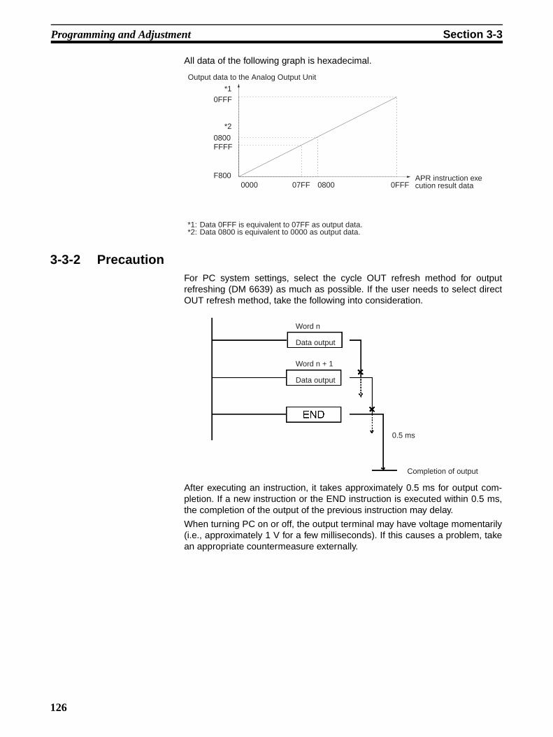
Programming and Adjustment Section 3-3
All data of the following graph is hexadecimal.
3-3-2 PrecautionFor PC system settings, select the cycle OUT refresh method for outputrefreshing (DM 6639) as much as possible. If the user needs to select directOUT refresh method, take the following into consideration.
After executing an instruction, it takes approximately 0.5 ms for output com-pletion. If a new instruction or the END instruction is executed within 0.5 ms,the completion of the output of the previous instruction may delay.
When turning PC on or off, the output terminal may have voltage momentarily(i.e., approximately 1 V for a few milliseconds). If this causes a problem, takean appropriate countermeasure externally.
Output data to the Analog Output Unit
*1
APR instruction execution result data0000 07FF 0800 0FFF
F800
FFFF0800
*2
*1: Data 0FFF is equivalent to 07FF as output data.*2: Data 0800 is equivalent to 0000 as output data.
0FFF
Word n
Data output
Word n + 1
Data output
0.5 ms
Completion of output
126
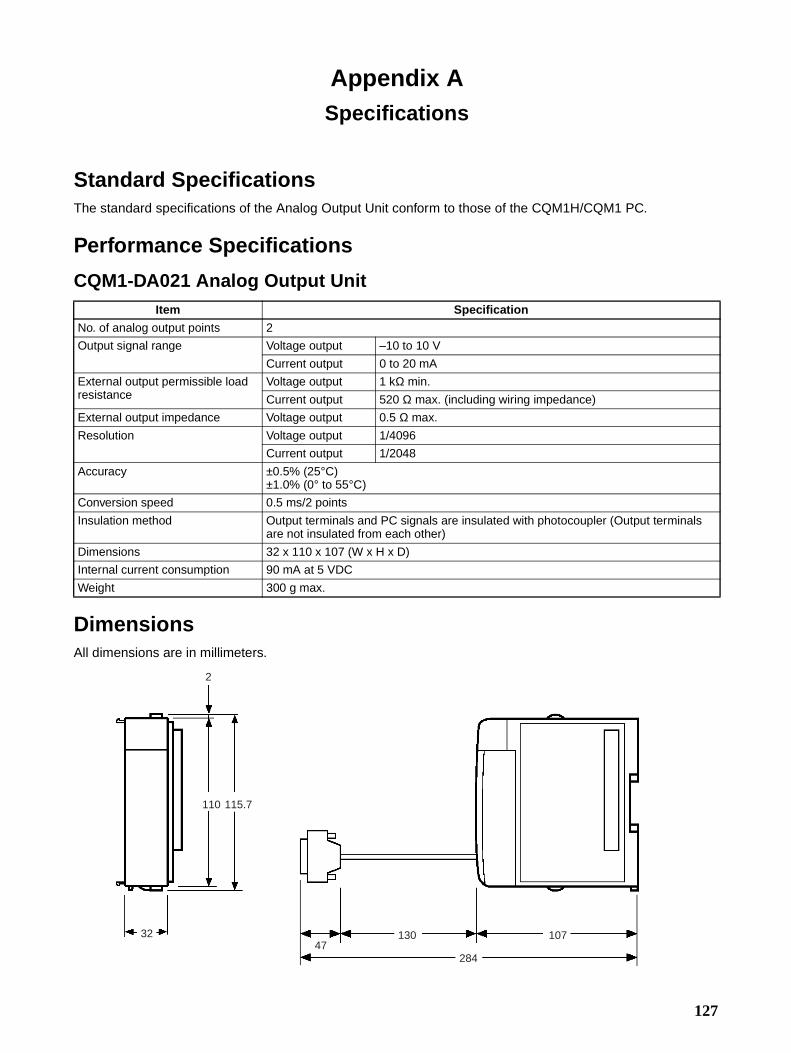
Appendix ASpecifications
Standard SpecificationsThe standard specifications of the Analog Output Unit conform to those of the CQM1H/CQM1 PC.
Performance Specifications
CQM1-DA021 Analog Output Unit
DimensionsAll dimensions are in millimeters.
Item Specification
No. of analog output points 2
Output signal range Voltage output –10 to 10 V
Current output 0 to 20 mA
External output permissible load resistance
Voltage output 1 kΩ min.
Current output 520 Ω max. (including wiring impedance)
External output impedance Voltage output 0.5 Ω max.
Resolution Voltage output 1/4096
Current output 1/2048
Accuracy ±0.5% (25°C)±1.0% (0° to 55°C)
Conversion speed 0.5 ms/2 points
Insulation method Output terminals and PC signals are insulated with photocoupler (Output terminals are not insulated from each other)
Dimensions 32 x 110 x 107 (W x H x D)
Internal current consumption 90 mA at 5 VDC
Weight 300 g max.
32
110 115.7
2
47130 107
284
127


Appendix BTroubleshooting
Analog Output UnitKind of error Phenomenon Cause Remedy
Indicator The RDY indicator is not lit. 1. The Unit is not connectedproperly.
2. No end cover is attached.
Refer to the CQM1H Operation Manual (W363) or the CQM1 Operation Manual (W226) and reset the Analog Output Unit.
Output The output voltage or current does not change when output data changes.
The power supply cable is not connected to the Analog Power Supply Unit.
Connect the power supply cable.
The output voltage or current does not match the output char-acteristics.
An external device with an impedance not within the per-missible range is connected.
Check if the impedance of the external device is within the per-missible range.
I/O Unit over The CPU has an I/O Unit over error.
The total number of words used by the Units connected exceeds the maximum available words of the CPU.
Each Analog Output Unit uses two words. Check if the total number of words is exceeding the maximum available words of the CPU.
129


PART VISensor Unit
CQM1-SEN01 Sensor UnitCQM1-TU001 Remote Console
E3X-MA11 Optical Fiber Photoelectric Module
E3C-MA11 Photoelectric ModuleE2C-MA11 Proximity Sensor Module
E39-M11 Dummy Module
131

SECTION 1Features and System Configuration
This section provides the features and system configuration relating to the Sensor Unit and dedicated sensor modules.
1-1 Features . . . . . . . . . . . . . . . . . . . . . . . . . . . . . . . . . . . . . . . . . . . . . . . . . . . . . . 134
1-2 System Configuration . . . . . . . . . . . . . . . . . . . . . . . . . . . . . . . . . . . . . . . . . . . 134
1-3 Connecting Devices . . . . . . . . . . . . . . . . . . . . . . . . . . . . . . . . . . . . . . . . . . . . 135
1-3-1 CPU Models . . . . . . . . . . . . . . . . . . . . . . . . . . . . . . . . . . . . . . . . . . . 135
1-3-2 Remote Console . . . . . . . . . . . . . . . . . . . . . . . . . . . . . . . . . . . . . . . . 135
1-3-3 Sensor Modules . . . . . . . . . . . . . . . . . . . . . . . . . . . . . . . . . . . . . . . . 135
1-3-4 Applicable Sensors . . . . . . . . . . . . . . . . . . . . . . . . . . . . . . . . . . . . . . 135
1-4 System Construction . . . . . . . . . . . . . . . . . . . . . . . . . . . . . . . . . . . . . . . . . . . . 136
133

Features Section 1-1
1-1 Features• A maximum of four sensor modules in any combination and order can be
mounted to a single CQM1-SEN01.
• Sensor modules can be connected to the CQM1-SEN01 via connectorsand the CQM1-SEN01 can supply power to the modules, thus greatly sav-ing wiring effort.
• The sensitivity of each sensor module is set by teaching. After power issupplied to sensor modules mounted to the CQM1-SEN01 and teachingis executed, the sensor modules will function properly. Teaching can beexecuted remotely by using the dedicated CQM1-TU001 Remote Console(sold separately).
• If the mode selector of each sensor module is set to SET, no signal istransmitted to the PC. Signals are transmitted according to the sensoroperation only when the mode selector is set to RUN.
• At the time of system testing, no signals from Sensor Units will beretrieved by the PC if the Programming Console connected to the PC is inprogram mode.
1-2 System ConfigurationThe CQM1-SEN01 is a four-point input unit that occupies one input word. Allbits, other than input bits, will not be used as work bits.
It is recommended that the CQM1-SEN01 be mounted to the left of theCQM1-OC@@@ Relay Contact Output Unit but not next to the CQM1-OC@@@ Relay Contact Output Unit, otherwise the sensor modules mountedto the CQM1-SEN01 will be influenced by noise that may be generated fromthe CQM1-OC@@@ Relay Contact Output Unit at the time of load switching.
The following illustration shows a CQM1H/CQM1 system configuration thatincludes the CQM1-SEN01.
A variety of sensor modules (four units max.)
CQM1-TU001 Remote Console
CQM1-SEN01 Sensor Unit
CQM1H/CQM1
134

Connecting Devices Section 1-3
1-3 Connecting Devices1-3-1 CPU Models
The Sensor Unit can be mounted to the following CPUs.
1-3-2 Remote ConsoleUse the mode setting selector of the dedicated CQM1-TU001 Remote Con-sole for the CQM1-SEN01 to set sensor modules mounted to the CQM1-SEN01 to operation monitor mode or teaching mode.
1-3-3 Sensor ModulesThe following dedicated sensor modules can be mounted to the CQM1-SEN01.
Note Mount the E39-M11 Dummy Module to any unused slot of the CQM1-SEN01for dust prevention.
1-3-4 Applicable SensorsThe following sensors can be used with the E3X-MA11 Optical Fiber Photo-electric Module.
Note The E3X-MA11 can be used with a variety of sensors in addition to thoselisted above. The E3X-MA11, however, cannot be used with the E32-DC9G,E32-DC9G4, E32-D61, or E32-D73.
Name ModelCQM1H-series CPU CQM1H-CPU11
CQM1H-CPU21
CQM1H-CPU51CQM1H-CPU61
CQM1-series CPU CQM1-CPU11-ECQM1-CPU21-ECQM1-CPU41-EV1
CQM1-CPU42-EV1CQM1-CPU43-EV1CQM1-CPU44-EV1
Name Model
Optical Fiber Photoelectric Module E3X-MA11
Photoelectric Module E3C-MA11
Proximity Sensor Module E2C-MA11
Dummy Module E39-M11
Sensing method Model
Thru-beam E32-T11L, E32-TC200, and E32-T11
Side view thru-beam E32-T14L
Heat-resistive thru-beam E32-T51
Screen thru-beam E32-T16
Reflective E32-D11L, E32-DC200, and E32-D11
Side view reflective E32-D14L
Heat-resistive reflective E32-D51
Retroreflective E32-R21
135

System Construction Section 1-4
The following sensors can be used with the E3C-MA11 Photoelectric Module.
The following sensors can be used with the E2C-MA11 Proximity SensorModule.
1-4 System ConstructionThe CQM1H/CQM1 treats the CQM1-SEN01 as a four-point Input Unit. Inputsare allocated from word 000 including the built-in input bits of the CPU of theCQM1H/CQM1.
The following is an example of word allocation. The CQM1-SEN01 occupiesone input word. Any bits without a sensor module cannot be used as workbits. Any bits connected to a dummy module is always OFF.
Example
Note Refer to 3-2-3 I/O Allocation of the CQM1H Programming Manual or 3-2 Allo-cating I/O Bits of the CQM1 Programming Manual for details on I/O word allo-cation.
Sensing method Model
Thru-beam E3C-S10, E3C-1, and E3C-2
Diffuse reflective E3C-DS5W, E3C-DS10
Convergent reflective E3C-LS3R
Mark detection reflective E3C-VS1G, E3C-VS3R, E3C-VM35R, and E3C-VS7R
• E2C-CR5B
• E2C-CR8A
• E2C-CR8B
• E2C-X1A
• E2C-C1A
• E2C-X1R5A
Word
CPU
000001
100101
IN 1
6 po
ints
CQM1H/CQM1
IN 1
6 po
ints
Out
16
poin
tsPS
PS : Power Supply UnitCPU : CPUIN : Input Unit and terminalsOUT : Output UnitSEN : Sensor UnitIN
16
poin
ts
Out
16
poin
ts
SE
N 4
poi
nts
002003
Slot no. Bit0123
00300003010030200303
136
SECTION 2Nomenclature and Functions
This section provides the nomenclature and switch settings for the CQM1-SEN01, CQM1-TU001, E3X-MA11, E3C-MA11, and E2C-MA11.
2-1 Nomenclature . . . . . . . . . . . . . . . . . . . . . . . . . . . . . . . . . . . . . . . . . . . . . . . . . 138
2-1-1 Sensor Unit . . . . . . . . . . . . . . . . . . . . . . . . . . . . . . . . . . . . . . . . . . . . 138
2-1-2 Remote Console . . . . . . . . . . . . . . . . . . . . . . . . . . . . . . . . . . . . . . . . 138
2-1-3 Optical Fiber Photoelectric Module . . . . . . . . . . . . . . . . . . . . . . . . . 140
2-1-4 Photoelectric Module . . . . . . . . . . . . . . . . . . . . . . . . . . . . . . . . . . . . 141
2-1-5 Proximity Sensor Module . . . . . . . . . . . . . . . . . . . . . . . . . . . . . . . . . 141
2-2 Switch Settings . . . . . . . . . . . . . . . . . . . . . . . . . . . . . . . . . . . . . . . . . . . . . . . . 142
2-2-1 E3X-MA11 Optical Fiber Photoelectric Module E3C-MA11
Photoelectric Module . . . . . . . . . . . . . . . . . . . . . . . . . . . . . . . . . . . . 142
2-2-2 E2C-MA11 Proximity Sensor Module . . . . . . . . . . . . . . . . . . . . . . . 143
137
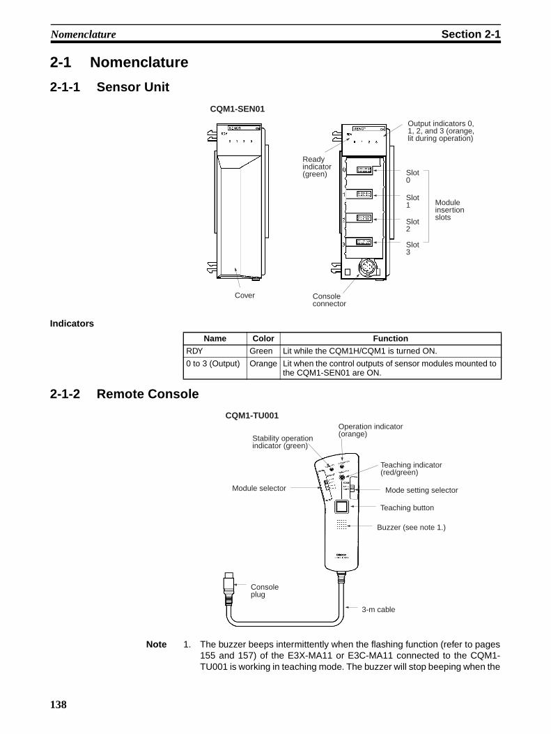
Nomenclature Section 2-1
2-1 Nomenclature
2-1-1 Sensor Unit
Indicators
2-1-2 Remote Console
Note 1. The buzzer beeps intermittently when the flashing function (refer to pages155 and 157) of the E3X-MA11 or E3C-MA11 connected to the CQM1-TU001 is working in teaching mode. The buzzer will stop beeping when the
Cover
Ready indicator (green)
Console connector
Output indicators 0, 1, 2, and 3 (orange, lit during operation)
Slot 0
Slot 1
Slot 2
Slot 3
Module insertion slots
CQM1-SEN01
Name Color Function
RDY Green Lit while the CQM1H/CQM1 is turned ON.
0 to 3 (Output) Orange Lit when the control outputs of sensor modules mounted to the CQM1-SEN01 are ON.
Console plug
3-m cable
Buzzer (see note 1.)
Teaching button
Mode setting selector
Teaching indicator (red/green)
Operation indicator (orange)Stability operation
indicator (green)
Module selector
CQM1-TU001
138
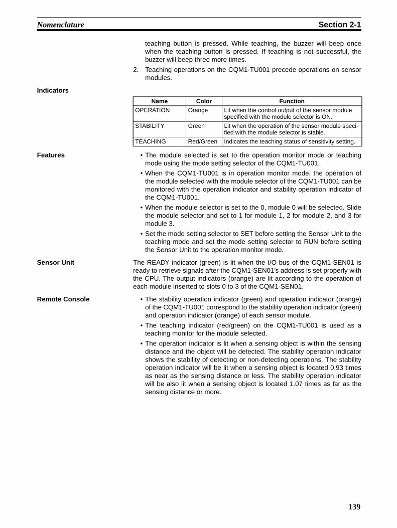
Nomenclature Section 2-1
teaching button is pressed. While teaching, the buzzer will beep oncewhen the teaching button is pressed. If teaching is not successful, thebuzzer will beep three more times.
2. Teaching operations on the CQM1-TU001 precede operations on sensormodules.
Indicators
Features • The module selected is set to the operation monitor mode or teachingmode using the mode setting selector of the CQM1-TU001.
• When the CQM1-TU001 is in operation monitor mode, the operation ofthe module selected with the module selector of the CQM1-TU001 can bemonitored with the operation indicator and stability operation indicator ofthe CQM1-TU001.
• When the module selector is set to the 0, module 0 will be selected. Slidethe module selector and set to 1 for module 1, 2 for module 2, and 3 formodule 3.
• Set the mode setting selector to SET before setting the Sensor Unit to theteaching mode and set the mode setting selector to RUN before settingthe Sensor Unit to the operation monitor mode.
Sensor Unit The READY indicator (green) is lit when the I/O bus of the CQM1-SEN01 isready to retrieve signals after the CQM1-SEN01’s address is set properly withthe CPU. The output indicators (orange) are lit according to the operation ofeach module inserted to slots 0 to 3 of the CQM1-SEN01.
Remote Console • The stability operation indicator (green) and operation indicator (orange)of the CQM1-TU001 correspond to the stability operation indicator (green)and operation indicator (orange) of each sensor module.
• The teaching indicator (red/green) on the CQM1-TU001 is used as ateaching monitor for the module selected.
• The operation indicator is lit when a sensing object is within the sensingdistance and the object will be detected. The stability operation indicatorshows the stability of detecting or non-detecting operations. The stabilityoperation indicator will be lit when a sensing object is located 0.93 timesas near as the sensing distance or less. The stability operation indicatorwill be also lit when a sensing object is located 1.07 times as far as thesensing distance or more.
Name Color Function
OPERATION Orange Lit when the control output of the sensor module specified with the module selector is ON.
STABILITY Green Lit when the operation of the sensor module speci-fied with the module selector is stable.
TEACHING Red/Green Indicates the teaching status of sensitivity setting.
139

Nomenclature Section 2-1
2-1-3 Optical Fiber Photoelectric Module
Indicators
Note When the mode selector is set to SET, the operation indicator and stabilityoperation indicator are used to monitor teaching. Refer to 2-2 Switch Settingsfor details.
Operation indica-tor (orange)
Stability operation indicator
Stable non-sensing zone
Stable sens-ing zone
OFF
ON
Setting distance x approx. 1.07
Setting distance
Setting distance x approx. 0.93
ON
OFF
ON
Fiber insertion mouth (light emitting terminal)
Fiber insertion mouth (light reception terminal)
Fiber lock leverFREE: Fiber is released.LOCK: Fiber is locked.
Teaching button
Mode selector (SET for teaching and RUN for normal operation.)
Operation indicator (orange)
Stability operation indicator (green)Front View
E3X-MA11
(Refer to 3-4-1 E3X-MA11 Optical Fiber Photoelectric Module for details.)
(Refer to 3-4-1 E3X-MA11 Optical Fiber Photoelectric Module for details.)
(Refer to 2-2 Switch Settings for details.)
Name Color Function
OPE Orange Lit when the control output is ON.
STAB Green Lit during stable light ON or dark ON, which can be selected with the operation mode selector.
Operation mode selectorL • on: Light OND • on: Dark ON
Timer selector0 ms: No timer10 ms: OFF-delay timer
Side View
(Refer to 2-2 Switch Settings for details.)
(Refer to 2-2 Switch Settings for details.)
140

Nomenclature Section 2-1
2-1-4 Photoelectric Module
Indicators
Note When the mode selector is set to SET, the operation indicator and stabilityoperation indicator are used to monitor teaching. Refer to 2-2 Switch Settingsfor details.
2-1-5 Proximity Sensor Module
Teaching button
Mode selector (SET for teaching and RUN for normal operation.)
Operation indicator (orange)
Stability operation indicator (green)Front View
E3C-MA11
Sensor code connection terminals
(Refer to 2-2 Switch Settings for details.)
(Refer to 3-4-2 E3C-MA11 Photoelectric Module for details.)
Name Color Function
OPE Orange Lit when the control output is ON.
STAB Green Lit during stable light ON or dark ON, which can be selected with the operation mode selector.
Operation mode selectorL • on: Light OND • on: Dark ON
Timer selector0 ms: No timer10 ms: OFF-delay timer
Side View
(Refer to 2-2 Switch Settings for details.)
(Refer to 2-2 Switch Settings for details.)
Sensor code connection terminals Teaching button
Mode selector (SET for teaching and RUN for normal operation)
Operation indicator (orange)
Stability operation indicator (green)Front View
E2C-MA11
(Refer to 3-4-3 E2C-MA11 Proximity Sensor Module for details.)
(Refer to 2-2-2 E2C-MA11 Proximity Sensor Module for details.)
141

Switch Settings Section 2-2
Indicators
Note When the mode selector is set to SET, the operation indicator and stabilityoperation indicator are used to monitor teaching. Refer to 4-1-1 E3X-MA11Optical Fiber Photoelectric Module for details.
2-2 Switch Settings
2-2-1 E3X-MA11 Optical Fiber Photoelectric ModuleE3C-MA11 Photoelectric Module
Operation Mode Selector
Timer Selector
Name Color Function
OPE Orange Lit when the control output is ON.
STAB Green The stability operation indicator shows the stability of detecting or non-detecting operations. The sta-bility operation indicator will be lit when a sensing object is located 0.93 times as near as the sensing distance or less. The stability operation indicator will be also lit when a sensing object is located 1.07 times as far as the sensing distance or more.
Cable length switchesTimer selector0 ms: No timer10 ms: OFF-delay timer
Side View
(Refer to 2-2-2 E2C-MA11 Proximity Sensor Module for details.)
(Refer to 2-2-2 E2C-MA11 Proximity Sensor Module for details.)
Setting Function
Light• on The control output is ON when there is light incident.
Dark• on The control output is ON when there is no light incident.
Setting Function
0 ms No timer
10 ms 10-ms OFF delay timer active
142

Switch Settings Section 2-2
Timing Charts
Note The operation mode selector and timer selector must be set before mountingthe E3X-MA11 to the Sensor Unit.
Mode Selector
2-2-2 E2C-MA11 Proximity Sensor ModuleCable Length Switches Set the switches as shown below to the length of sensor cable being used
either for standard cable lengths or after cutting the cable.
Note 1. If two cables of the same length and diameter are being attached togetherin parallel, position one of the cables 1 m above or below the other.
2. Set all switches to the right for the E2C-CR5B.
Timer Switch
Timer selector set to OFF (0ms) Timer selector set to ON (10 ms)
Operation indicator (orange)
ON
OFF
Control outputONOFF
Light receivedLight not received
Operation mode selector set to L • on (Light ON)
10 ms
Operation mode selector set to L • on (Light ON)
Operation indicator (orange)
ON
OFF
Control outputONOFF
Light receivedLight not received
Operation mode selector set to D • on (Dark ON)
Operation indicator (orange)
ON
OFF
Control outputONOFF
Light receivedLight not received
Operation mode selector set to D • on (Dark ON)
10 ms
Operation indicator (orange)
ON
OFF
Control outputONOFF
Light receivedLight not received
Setting Function
RUN Normal operation
SET Axis adjustment or sensitivity adjustment (teaching).
Sensor Cable length
0 to 1 m 1 to 2 m 2 to 3 m 3 to 4 m 4 to 5 m
E2C-CR8AE2C-CR8BE2C-X1AE2C-C1AE2C-X1R5A
Position of the switches of the Amplifier Unit
A
B
C
D
Knob position
A
B
C
D
A
B
C
D
A
B
C
D
A
B
C
D
Setting Function
0 ms No timer
10 ms 10-ms Off-delay timer active
143

Switch Settings Section 2-2
The following is an example of a sensor output operation chart.
Note Set the switches on the side panel before mounting the Module to the SensorUnit.
Mode Selector
Note 1. Refer to 3-4-1 E3X-MA11 Optical Fiber Photoelectric Module for the fiberlock lever of the E3X-MA11.
2. Refer to SECTION 4 Sensor Module Operation for details on the operationof the mode selector and teaching button.
10 msON OFF
ON OFF
Sensing distance
Approx. 107%Setting distance → 100%
hControl output (OFF-delay activated)
Control output(OFF-delay deactivated)
Operation indicator (orange)
Stability operation indicator (green)
Approx. 93%
ON OFF
ON OFF
Setting Function
RUN Normal operation
SET Sensitivity adjustment (teaching)
144

SECTION 3Connections
This section describes the connections between the CQM1-SEN01 and E3X-MA11, E3C-MA11, E2C-MA11, and CQM1-TU001.
3-1 Wiring Precaution . . . . . . . . . . . . . . . . . . . . . . . . . . . . . . . . . . . . . . . . . . . . . . 146
3-1-1 E3X-MA11 Optical Fiber Photoelectric Module . . . . . . . . . . . . . . . 146
3-1-2 Connecting Sensors to the E3C-MA11. . . . . . . . . . . . . . . . . . . . . . . 146
3-1-3 Connecting Sensors to the E2C-MA11. . . . . . . . . . . . . . . . . . . . . . . 147
3-2 Mounting and Dismounting the Sensor Module . . . . . . . . . . . . . . . . . . . . . . . 148
3-3 Connection of CQM1-TU001 Remote Console . . . . . . . . . . . . . . . . . . . . . . . 149
3-4 Connection of a Variety of Sensors. . . . . . . . . . . . . . . . . . . . . . . . . . . . . . . . . 149
3-4-1 E3X-MA11 Optical Fiber Photoelectric Module . . . . . . . . . . . . . . . 149
3-4-2 E3C-MA11 Photoelectric Module . . . . . . . . . . . . . . . . . . . . . . . . . . 152
3-4-3 E2C-MA11 Proximity Sensor Module . . . . . . . . . . . . . . . . . . . . . . . 152
145

Wiring Precaution Section 3-1
3-1 Wiring Precaution
3-1-1 E3X-MA11 Optical Fiber Photoelectric ModuleFiber Head The tightening torque applied to the fiber head of each Fiber Unit should be as
follows:
Use a proper sized wrench.
3-1-2 Connecting Sensors to the E3C-MA11 Strip the vinyl insulation off all the connection cords 12 mm from the ends forthe receiver and projector terminals and expose each conductor 6 mm fromthe end of the conductor. Due to the small terminals, be careful not to shortthe wires when wiring.
The length of the cable connected to the terminals of the E3C-MA11 must be10 m maximum without any extension terminals.
Fiber Unit Tightening torque
M3/M4 screw 0.78 N • m max.
M6 screw 0.98 N • m max.
3-mm-dia. column 0.29 N • m max.
E32-D14L 0.98 N • m max.
E32-T16 0.49 N • m max.
E32-R21 0.59 N • m max.
Retaining screw (M 3 max.)Spring mounting clip
Toothed washers
Nuts(attachment)
Screw-mounting Model Column Model
6 mm max.
12 mm max.
146

Wiring Precaution Section 3-1
3-1-3 Connecting Sensors to the E2C-MA11 Do not use excessive force when securing the nut for E2C-X-series sensors.Always use a toothed washer.
Note The above tightening torques assume that a toothed washer is being used.
Cylindrical Sensors without Screws
Use the following tightening torque when attaching a sensor with a set screw:0.2 N • m max.
Effects of Surrounding Metal
When mounting the sensor within a metal panel, ensure that the clearancesgiven in the following table are maintained.
Note Diameters (d) in parentheses are the external diameters for shielded sensors.Although the E2C-CR5B is a shielded sensor, it cannot be mounted within ametal panel.
Model Tightening torque
E2C-X1A 0.98 N • m
E2C-X1R5A 2.0 N • m
Set screw (M3) hole
Dedicated Y92E-F3R5 Mounting Bracket for 3.5 dia. screws (sold separately)
The Y92E-F5R4 for 5.4 dia. screws is sold separately.
7 to11.5 mm
Model Dimension (mm)
I d D m
E2C-CR5B 2 6 2 1.5
E2C-CR8@ 0 (3.5) 0 2.4
E2C-X1A 0 (5) 0 3
E2C-C1A 0 (5.4) 0 3
E2C-X1R5A 0 (8) 0 4.5
m
l
dia. : d
D
147
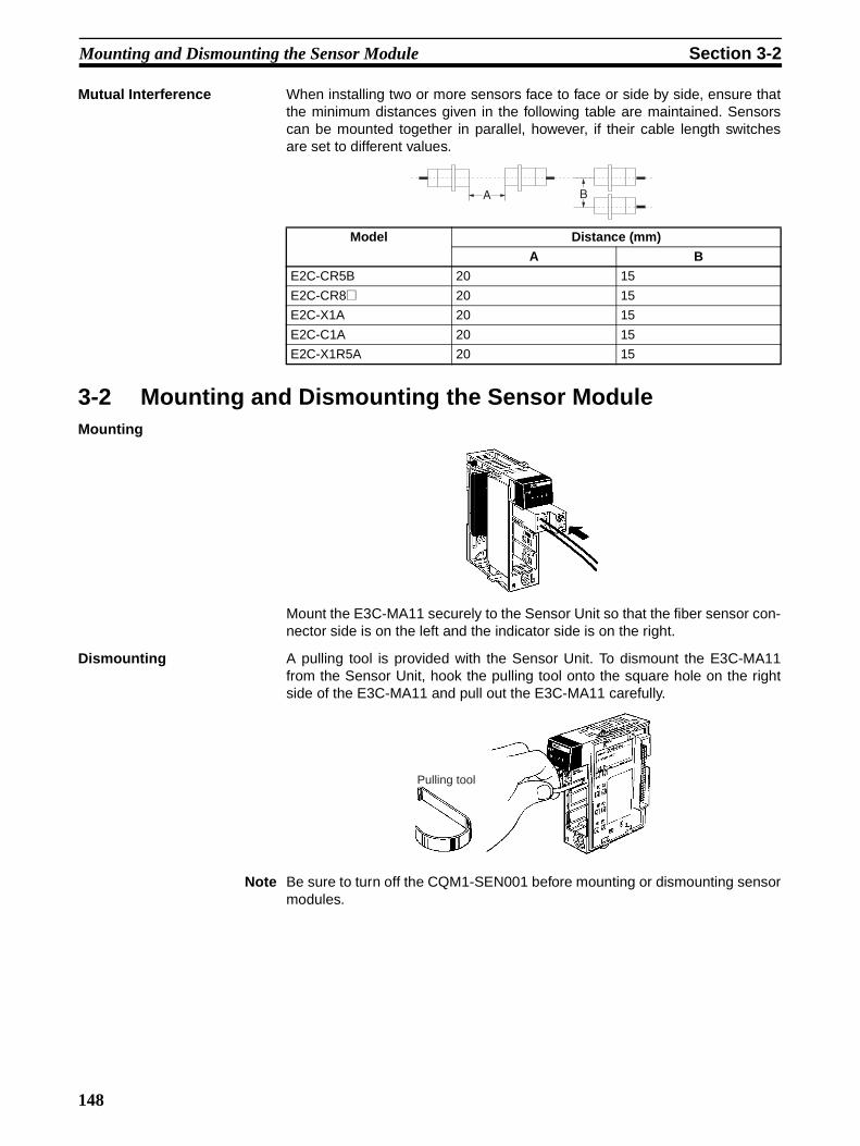
Mounting and Dismounting the Sensor Module Section 3-2
Mutual Interference When installing two or more sensors face to face or side by side, ensure thatthe minimum distances given in the following table are maintained. Sensorscan be mounted together in parallel, however, if their cable length switchesare set to different values.
3-2 Mounting and Dismounting the Sensor ModuleMounting
Mount the E3C-MA11 securely to the Sensor Unit so that the fiber sensor con-nector side is on the left and the indicator side is on the right.
Dismounting A pulling tool is provided with the Sensor Unit. To dismount the E3C-MA11from the Sensor Unit, hook the pulling tool onto the square hole on the rightside of the E3C-MA11 and pull out the E3C-MA11 carefully.
Note Be sure to turn off the CQM1-SEN001 before mounting or dismounting sensormodules.
Model Distance (mm)
A B
E2C-CR5B 20 15
E2C-CR8@ 20 15
E2C-X1A 20 15
E2C-C1A 20 15
E2C-X1R5A 20 15
A B
Pulling tool
148

Connection of CQM1-TU001 Remote Console Section 3-3
3-3 Connection of CQM1-TU001 Remote Console• Remove the cover of the Unit and insert the console plug into the console
connector of the Unit so that the polarity of the console plug and the con-sole connector will match.
• The console connector does not incorporate a lock mechanism. To dis-connect the console plug, hold the console plug and pull it straight out.
• It is not possible to mount the cover to the Unit if the console plug is con-nected to the console connector.
• The console plug can be disconnected from the console connector even ifthe Unit is turned on. Do not, however, disconnect the console plug whilethe sensitivity of the Unit is being adjusted.
3-4 Connection of a Variety of Sensors
3-4-1 E3X-MA11 Optical Fiber Photoelectric ModuleConnecting Fibers Set the fiber lock lever of the E3X-MA11 to FREE before inserting an optical
fiber cable to a fiber insertion mouth of the E3X-MA11 as shown in the follow-ing illustration.
After inserting two optical fiber cables from the Fiber Units to the fiber inser-tion mouths of the E3X-MA11, set the fiber lock lever to LOCK to secure theoptical fiber cables.
Insert the optical fiber cables into the E3X-MA11 before mounting the E3X-MA11 to the Sensor Unit.
Note If the tips of the two optical fiber cables are not inserted into the E3X-MA11 tothe insertion marks, the sensing distance may be reduced.
Disconnecting Fibers To disconnect the optical fiber cables from the E3X-MA11, hold and pull outthe optical fiber cables carefully. Before disconnecting the optical fiber cablesfrom the E3X-MA11, be sure to set the fiber lock lever to FREE.
Insertion mark
149
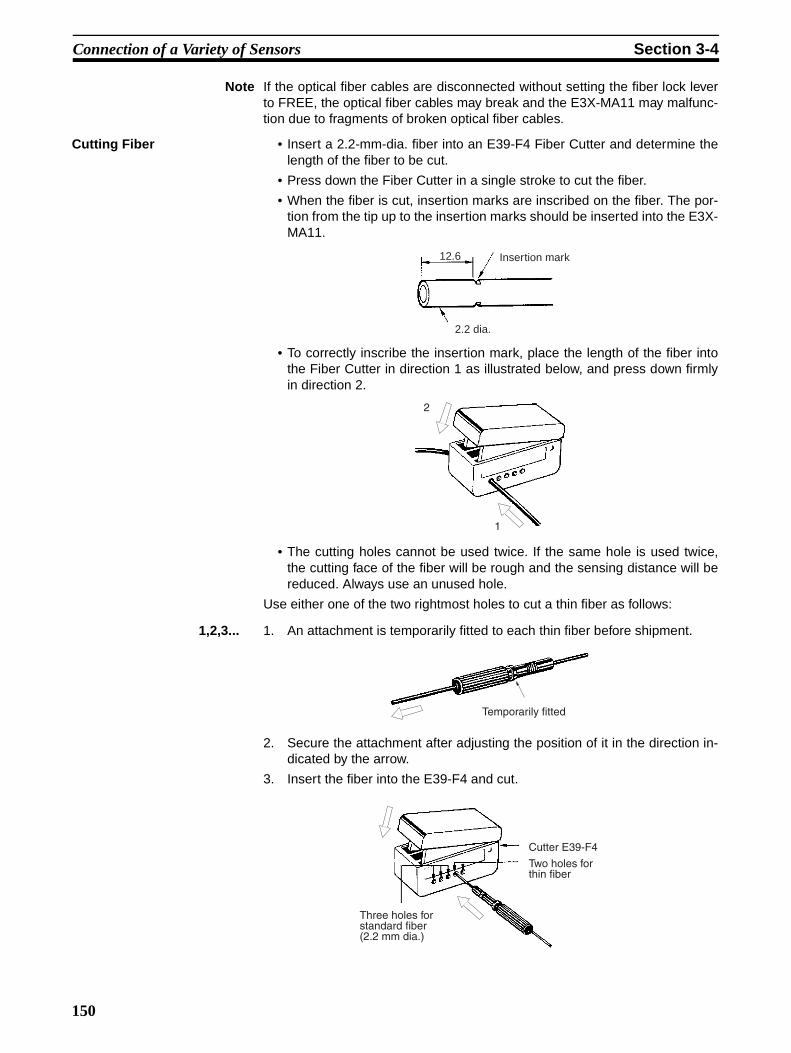
Connection of a Variety of Sensors Section 3-4
Note If the optical fiber cables are disconnected without setting the fiber lock leverto FREE, the optical fiber cables may break and the E3X-MA11 may malfunc-tion due to fragments of broken optical fiber cables.
Cutting Fiber • Insert a 2.2-mm-dia. fiber into an E39-F4 Fiber Cutter and determine thelength of the fiber to be cut.
• Press down the Fiber Cutter in a single stroke to cut the fiber.
• When the fiber is cut, insertion marks are inscribed on the fiber. The por-tion from the tip up to the insertion marks should be inserted into the E3X-MA11.
• To correctly inscribe the insertion mark, place the length of the fiber intothe Fiber Cutter in direction 1 as illustrated below, and press down firmlyin direction 2.
• The cutting holes cannot be used twice. If the same hole is used twice,the cutting face of the fiber will be rough and the sensing distance will bereduced. Always use an unused hole.
Use either one of the two rightmost holes to cut a thin fiber as follows:
1,2,3... 1. An attachment is temporarily fitted to each thin fiber before shipment.
2. Secure the attachment after adjusting the position of it in the direction in-dicated by the arrow.
3. Insert the fiber into the E39-F4 and cut.
12.6 Insertion mark
2.2 dia.
1
2
Temporarily fitted
Three holes for standard fiber (2.2 mm dia.)
Cutter E39-F4
Two holes for thin fiber
150
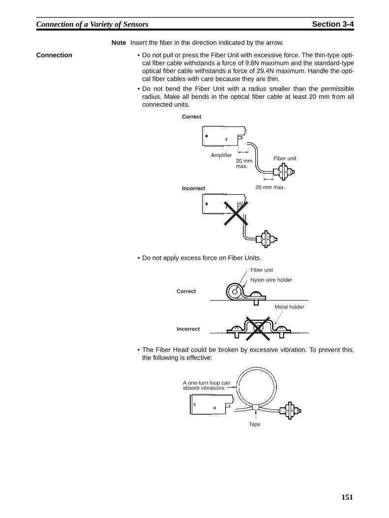
Connection of a Variety of Sensors Section 3-4
Note Insert the fiber in the direction indicated by the arrow.
Connection • Do not pull or press the Fiber Unit with excessive force. The thin-type opti-cal fiber cable withstands a force of 9.8N maximum and the standard-typeoptical fiber cable withstands a force of 29.4N maximum. Handle the opti-cal fiber cables with care because they are thin.
• Do not bend the Fiber Unit with a radius smaller than the permissibleradius. Make all bends in the optical fiber cable at least 20 mm from allconnected units.
• Do not apply excess force on Fiber Units.
• The Fiber Head could be broken by excessive vibration. To prevent this,the following is effective:
AmplifierFiber unit
20 mm max.
Correct
Incorrect
20 mm max.
Fiber unit
Nylon wire holder
Correct
Incorrect
Metal holder
A one-turn loop can absorb vibrations.
Tape
151

Connection of a Variety of Sensors Section 3-4
3-4-2 E3C-MA11 Photoelectric ModuleConnection
Note 1. Strip the vinyl insulation off all the connection cords 12 mm from the endsfor the receiver and projector terminals and expose each conductor 6 mmfrom the end of the conductor. Due to the small terminals, be careful not toshort the wires when wiring.
2. The length of the cable connected to the terminals of the E3C-MA11 mustbe 10 m maximum without any extension terminals.
3-4-3 E2C-MA11 Proximity Sensor ModuleConnection
1
2
3
4
Red
White
Thru-beam model
Shield
Shield
1
2
3
4
White
Red
Reflective model
Shield
Shield
3
4
Proximity sensor
E2C-MA11 Prox-imity Module
Shield
152

SECTION 4Sensor Module Operation
This section provides information on the operation of the CQM1-SEN01.
4-1 Operation without CQM1-TU001 Remote Console . . . . . . . . . . . . . . . . . . . . 154
4-1-1 E3X-MA11 Optical Fiber Photoelectric Module . . . . . . . . . . . . . . . 154
4-1-2 E3C-MA11 Photoelectric Module . . . . . . . . . . . . . . . . . . . . . . . . . . 156
4-1-3 E2C-MA11 Proximity Sensor Module . . . . . . . . . . . . . . . . . . . . . . . 157
153

Operation without CQM1-TU001 Remote Console Section 4-1
4-1 Operation without CQM1-TU001 Remote ConsoleWhen the CQM1-TU001 is connected to the CQM1-SEN01, operations on theCQM1-TU001 precede operations on sensor modules. Operations withoutconnecting the CQM1-TU001 is explained hereunder.
4-1-1 E3X-MA11 Optical Fiber Photoelectric ModuleSensitivity Adjustment There are three sensitivity adjustment methods. Choose the most optimum
method according to the application.
Maximum Sensitivity Setting
Use the following procedure to set for maximum sensitivity
1,2,3... 1. Set the mode selector to SET. When using a thru-beam fiber sensor, adjustthe optical axis using the flashing function of the thru-beam fiber sensor.
2. Press the teaching button for 3 s minimum. The teaching indicator will turnfrom orange to green in 3 s.
3. Set the mode selector to RUN to complete the maximum sensitivity settingof the E3X-MA11.
Note The maximum sensitivity of the Sensor Unit can be automatically set regard-less of the set distance or light reception.
Teaching without a Sensing Object (Only for Diffusive Reflective Sensor)
If any background object exerts an influence when setting the maximum sen-sitivity on the E3X-MA11, try the following method.
1,2,3... 1. Locate the sensor head in the sensing range of the sensor.
2. Set the mode selector to SET.
3. Press the teaching button. The teaching indicator (orange) will be lit.
4. Set the mode selector to RUN. If teaching is successful, the stability oper-ation indicator (green) will be lit. If teaching is unsuccessful, the stabilityoperation indicator will flash. In this case make sure that the optical fibercable of the sensor is connected securely, and then change the sensingdistance that has been set and repeat from step 2.
Note The sensitivity of the E3X-MA11 is set to maximum if teaching is performedwith very little light or if the sensor head is not located within the sensing dis-tance. If stable detection of objects is not possible after teaching, try teachingwith a sensing object as described in the following.
Teaching with a Sensing Object
Teaching with a sensing object is recommended if delicate sensing operationis required.
1,2,3... 1. Locate the sensor head in the sensing range of the sensor.
2. Set the mode selector to SET. When using a thru-beam fiber sensor, adjustthe optical axis using the flashing function of the thru-beam fiber sensor.
3. Locate the object at the sensing position and press the teaching button.
The teaching indicator will turn orange.
Light is not received.
Mark
Base
154

Operation without CQM1-TU001 Remote Console Section 4-1
4. Move the object and press the teaching button. If teaching is successful,the teaching indicator will turn from orange to green. If teaching is unsuc-cessful, the teaching indicator (orange) will flash, in which case change theposition of the object and the sensing distance that have been set and re-peat from step 3.
5. Set the mode selector to RUN to complete the sensitivity setting on theE3X-MA11.
Light Axis Adjustment with Flashing Function
• This function enables the user to easily adjust the light axis of a thru-beam fiber with the light source flashing.
• If the light projection fiber head axis and the light reception fiber head axisdo not agree with each other, and the amount of light received becomes90% of the peak value or less, the flashing function of the E3X-MA11 willoperate. The E3X-MA11 retains the peak value when the mode selector isset to SET so that the axes of the fiber heads can be easily adjusted toagree with each other. When the axes agree, the tip of the fiber for lightemission will be lit.
• If a Remote Console is connected to the Sensor Unit, the buzzer of theRemote Console will beep intermittently when the flashing function startsoperating. The buzzer will stop beeping when the axes agree and the tipof the fiber for light emission is lit.
• Teaching is possible by pressing the teaching button while the flashingfunction is operating.
Light is received.
Mark
Base
Optical input
The peak of light reception90% of the peak value
Lit in this range.
Angle of the head (θ)
Flashing Lit Flashing
Fiber for light emission Fiber for light reception
θ
155

Operation without CQM1-TU001 Remote Console Section 4-1
4-1-2 E3C-MA11 Photoelectric ModuleSensitivity Adjustment There are three sensitivity adjustment methods. Choose the most optimum
method according to the application.
Maximum Sensitivity Setting
1,2,3... 1. Set the mode selector to SET. When using a thru-beam fiber sensor, adjustthe optical axis using the flashing function of the thru-beam fiber sensor.
2. Press the teaching button for 3 s minimum. The teaching indicator will turnfrom orange to green in 3 s.
3. Set the mode selector to RUN to complete the maximum sensitivity settingof the E3C-MA11.
Note The maximum sensitivity of the Sensor Unit can be automatically set regard-less of the set distance or light reception.
Teaching without a Sensing Object (Only for Diffusive Reflective Sensor)
If any background object exerts an influence when setting the maximum sen-sitivity on the ECX-MA11, try the following method.
1,2,3... 1. Locate the sensor head in the sensing range of the sensor.
2. Set the mode selector to SET.
3. Press the teaching button. The teaching indicator (orange) will be lit.
4. Set the mode selector to RUN. If teaching is successful, the stability oper-ation indicator (green) will be lit. If teaching is unsuccessful, the stabilityoperation indicator will flash. In this case make sure that the sensor cableis connected securely, and then change the sensing distance that hasbeen set and repeat from step 2.
Note The sensitivity of the E3C-MA11 is set to maximum if teaching is performedwith very little light or if the sensor head is not located within the sensing dis-tance. If stable detection of objects is not possible after teaching, try teachingwith a sensing object as described in the following.
Teaching with a Sensing Object
Teaching with a sensing object is recommended if delicate sensing operationis required.
1,2,3... 1. Locate the sensor head in the sensing range of the sensor.
2. Set the mode selector to SET. When using a thru-beam fiber sensor, adjustthe optical axis using the flashing function of the thru-beam fiber sensor.
3. Locate the object at the sensing position and press the teaching button.
The teaching indicator will turn orange.
4. Move the object and press the teaching button. If teaching is successful,the teaching indicator will turn from orange to green. If teaching is unsuc-cessful, the teaching indicator (orange) will flash, in which case change the
Sensing objectNo sensing object
Bac
kgro
und
obje
ct
Mar
k de
tect
ion
Mark detected
156

Operation without CQM1-TU001 Remote Console Section 4-1
position of the object and the sensing distance that have been set and re-peat from step 3.
5. Set the mode selector to RUN to complete the sensitivity setting on theE3X-MA11.
Light Axis Adjustment with Flashing Function
If the light projection fiber head axis and the light reception fiber head axis donot agree with each other, and the amount of light received becomes 90% ofthe peak value or less, the flashing function of the E3C-MA11 will operate.The E3C-MA11 retains the peak value when the mode selector is set to SETso that the axes of the fiber heads can be easily adjusted to agree with eachother. When the axes agree, the indicator on the light projection fiber head willbe lit. The E3C-DS10T does not incorporate an indicator on the light projec-tion fiber head.The indicator on the light projection fiber head will work as an operation indi-cator when the E3C-MA11 is in RUN mode.
4-1-3 E2C-MA11 Proximity Sensor ModuleBe sure to perform teaching before using the E2C-MA11 Proximity SensorModule.
Sensitivity Adjustment There are three sensitivity adjustment methods. Choose the most idealmethod according to the application.
Teaching without a Sensing Object
Teaching without a sensing object is recommended when using the E2C-MA11 as a standard proximity sensor.
1,2,3... 1. Locate the sensor head in the sensing range of the sensor.
2. Set the mode selector to SET.
With sensing object
Bac
kgro
und
obje
ct
Mark not detected
Optical input
The peak of light reception90% of the peak value
Lit in this range.
Angle of the head (θ)
Flashing Lit Flashing
Indicator
Sensor head for light emission
Sensor head for light reception
157
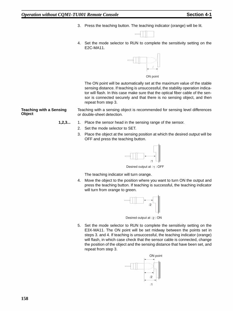
Operation without CQM1-TU001 Remote Console Section 4-1
3. Press the teaching button. The teaching indicator (orange) will be lit.
4. Set the mode selector to RUN to complete the sensitivity setting on theE2C-MA11.
The ON point will be automatically set at the maximum value of the stablesensing distance. If teaching is unsuccessful, the stability operation indica-tor will flash. In this case make sure that the optical fiber cable of the sen-sor is connected securely and that there is no sensing object, and thenrepeat from step 3.
Teaching with a Sensing Object
Teaching with a sensing object is recommended for sensing level differencesor double-sheet detection.
1,2,3... 1. Place the sensor head in the sensing range of the sensor.
2. Set the mode selector to SET.
3. Place the object at the sensing position at which the desired output will beOFF and press the teaching button.
The teaching indicator will turn orange.
4. Move the object to the position where you want to turn ON the output andpress the teaching button. If teaching is successful, the teaching indicatorwill turn from orange to green.
5. Set the mode selector to RUN to complete the sensitivity setting on theE3X-MA11. The ON point will be set midway between the points set insteps 3. and 4. If teaching is unsuccessful, the teaching indicator (orange)will flash, in which case check that the sensor cable is connected, changethe position of the object and the sensing distance that have been set, andrepeat from step 3.
ON point
l1
Desired output at l1 : OFF
l2
Desired output at l2 : ON
l1
ON point
l2
158
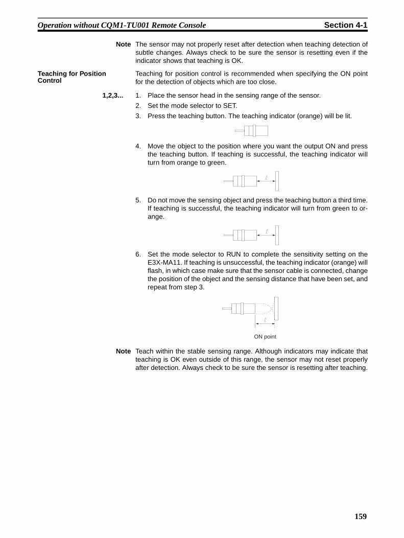
Operation without CQM1-TU001 Remote Console Section 4-1
Note The sensor may not properly reset after detection when teaching detection ofsubtle changes. Always check to be sure the sensor is resetting even if theindicator shows that teaching is OK.
Teaching for Position Control
Teaching for position control is recommended when specifying the ON pointfor the detection of objects which are too close.
1,2,3... 1. Place the sensor head in the sensing range of the sensor.
2. Set the mode selector to SET.
3. Press the teaching button. The teaching indicator (orange) will be lit.
4. Move the object to the position where you want the output ON and pressthe teaching button. If teaching is successful, the teaching indicator willturn from orange to green.
5. Do not move the sensing object and press the teaching button a third time.If teaching is successful, the teaching indicator will turn from green to or-ange.
6. Set the mode selector to RUN to complete the sensitivity setting on theE3X-MA11. If teaching is unsuccessful, the teaching indicator (orange) willflash, in which case make sure that the sensor cable is connected, changethe position of the object and the sensing distance that have been set, andrepeat from step 3.
Note Teach within the stable sensing range. Although indicators may indicate thatteaching is OK even outside of this range, the sensor may not reset properlyafter detection. Always check to be sure the sensor is resetting after teaching.
ON point
159


SECTION 5Remote Console Operation
This section provides information on the operation of the CQM1-TU001 Remote Console.
5-1 Mode Setting . . . . . . . . . . . . . . . . . . . . . . . . . . . . . . . . . . . . . . . . . . . . . . . . . . 162
5-2 Sensitivity Adjustment . . . . . . . . . . . . . . . . . . . . . . . . . . . . . . . . . . . . . . . . . . 162
5-2-1 E3X-MA11 Optical Fiber Photoelectric Module
E3C-MA11 Photoelectric Module . . . . . . . . . . . . . . . . . . . . . . . . . . 162
5-2-2 E2C-MA11 Proximity Sensor Module . . . . . . . . . . . . . . . . . . . . . . . 163
161
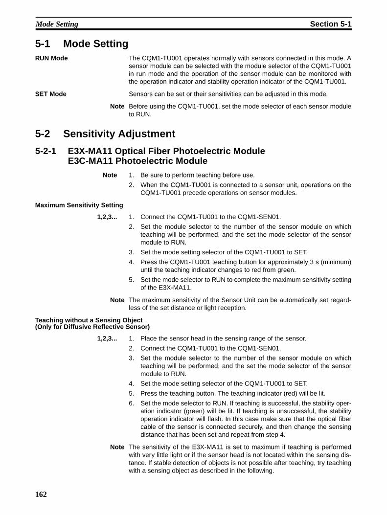
Mode Setting Section 5-1
5-1 Mode SettingRUN Mode The CQM1-TU001 operates normally with sensors connected in this mode. A
sensor module can be selected with the module selector of the CQM1-TU001in run mode and the operation of the sensor module can be monitored withthe operation indicator and stability operation indicator of the CQM1-TU001.
SET Mode Sensors can be set or their sensitivities can be adjusted in this mode.
Note Before using the CQM1-TU001, set the mode selector of each sensor moduleto RUN.
5-2 Sensitivity Adjustment
5-2-1 E3X-MA11 Optical Fiber Photoelectric ModuleE3C-MA11 Photoelectric Module
Note 1. Be sure to perform teaching before use.
2. When the CQM1-TU001 is connected to a sensor unit, operations on theCQM1-TU001 precede operations on sensor modules.
Maximum Sensitivity Setting
1,2,3... 1. Connect the CQM1-TU001 to the CQM1-SEN01.
2. Set the module selector to the number of the sensor module on whichteaching will be performed, and the set the mode selector of the sensormodule to RUN.
3. Set the mode setting selector of the CQM1-TU001 to SET.
4. Press the CQM1-TU001 teaching button for approximately 3 s (minimum)until the teaching indicator changes to red from green.
5. Set the mode selector to RUN to complete the maximum sensitivity settingof the E3X-MA11.
Note The maximum sensitivity of the Sensor Unit can be automatically set regard-less of the set distance or light reception.
Teaching without a Sensing Object(Only for Diffusive Reflective Sensor)
1,2,3... 1. Place the sensor head in the sensing range of the sensor.
2. Connect the CQM1-TU001 to the CQM1-SEN01.
3. Set the module selector to the number of the sensor module on whichteaching will be performed, and the set the mode selector of the sensormodule to RUN.
4. Set the mode setting selector of the CQM1-TU001 to SET.
5. Press the teaching button. The teaching indicator (red) will be lit.
6. Set the mode selector to RUN. If teaching is successful, the stability oper-ation indicator (green) will be lit. If teaching is unsuccessful, the stabilityoperation indicator will flash. In this case make sure that the optical fibercable of the sensor is connected securely, and then change the sensingdistance that has been set and repeat from step 4.
Note The sensitivity of the E3X-MA11 is set to maximum if teaching is performedwith very little light or if the sensor head is not located within the sensing dis-tance. If stable detection of objects is not possible after teaching, try teachingwith a sensing object as described in the following.
162

Sensitivity Adjustment Section 5-2
Teaching with a Sensing Object
1,2,3... 1. Place the sensor head in the sensing range of the sensor.
2. Connect the CQM1-TU001 to the CQM1-SEN01.
3. Set the module selector to the number of the sensor module on whichteaching will be performed, and the set the mode selector of the sensormodule to RUN.
4. Set the mode setting selector of the CQM1-TU001 to SET.
5. Place the object at the sensing position and press the teaching button. Theteaching indicator will turn red.
6. Move the object and press the teaching button. If teaching is successful,the teaching indicator will turn from red to green. If teaching is unsuccess-ful, the teaching indicator (red) will flash, in which case change the positionof the object and the sensing distance that have been set and repeat fromstep 5.
7. Set the mode selector to RUN to complete the sensitivity setting on theE3X-MA11.
5-2-2 E2C-MA11 Proximity Sensor ModuleNote 1. Be sure to perform teaching before use.
2. When the CQM1-TU001 is connected to a sensor unit, operations on theCQM1-TU001 precede operations on sensor modules.
Teaching without a Sensing Object
1,2,3... 1. Place the sensor head in the sensing range of the sensor.
2. Connect the CQM1-TU001 to the CQM1-SEN01.
3. Set the module selector to the number of the sensor module on whichteaching will be performed.
4. Set the mode setting selector of the CQM1-TU001 to SET.
5. Press the teaching button. The teaching indicator (red) will be lit.
6. Set the mode selector to RUN to complete the sensitivity setting on theE2C-MA11. If teaching is unsuccessful, the teaching indicator will flash. Inthis case make sure that the optical fiber cable of the sensor is connectedsecurely and that there is no sensing object, and then repeat from step 5.
Teaching with a Sensing Object
1,2,3... 1. Place the sensor head in the sensing range of the sensor.
2. Connect the CQM1-TU001 to the CQM1-SEN01.
3. Set the module selector to the number of the sensor module on whichteaching will be performed.
4. Set the mode setting selector of the CQM1-TU001 to SET.
5. Place the object at the sensing position at which the desired output will beOFF and press the teaching button. The teaching indicator will turn red.
6. Move the object to the position where you want to turn ON the output andpress the teaching button. If teaching is successful, the teaching indicatorwill turn from red to green.
7. Set the mode selector to RUN to complete the sensitivity setting on theE3X-MA11. If teaching is unsuccessful, the teaching indicator (red) willflash, in which case make sure that the sensor cable is connected, changethe position of the object and the sensing distance that have been set, andrepeat from step 5.
163
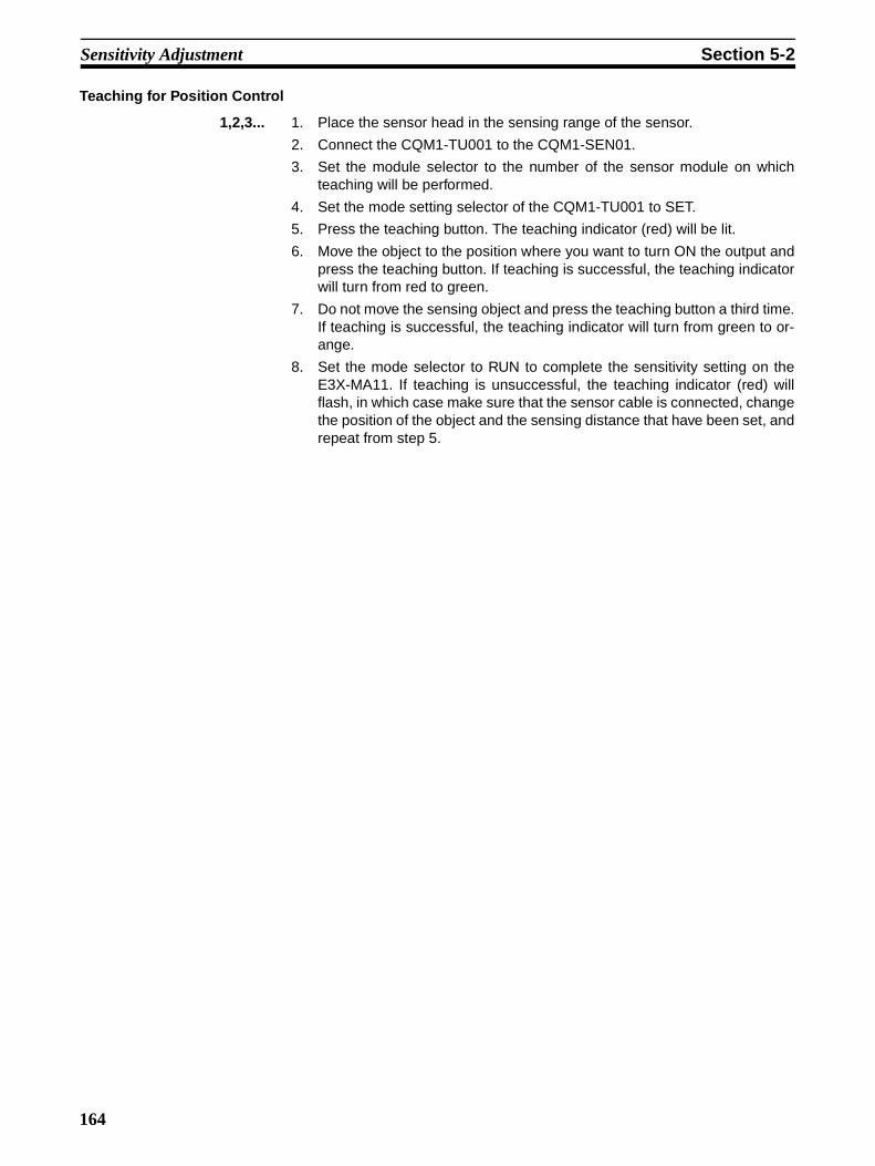
Sensitivity Adjustment Section 5-2
Teaching for Position Control
1,2,3... 1. Place the sensor head in the sensing range of the sensor.
2. Connect the CQM1-TU001 to the CQM1-SEN01.
3. Set the module selector to the number of the sensor module on whichteaching will be performed.
4. Set the mode setting selector of the CQM1-TU001 to SET.
5. Press the teaching button. The teaching indicator (red) will be lit.
6. Move the object to the position where you want to turn ON the output andpress the teaching button. If teaching is successful, the teaching indicatorwill turn from red to green.
7. Do not move the sensing object and press the teaching button a third time.If teaching is successful, the teaching indicator will turn from green to or-ange.
8. Set the mode selector to RUN to complete the sensitivity setting on theE3X-MA11. If teaching is unsuccessful, the teaching indicator (red) willflash, in which case make sure that the sensor cable is connected, changethe position of the object and the sensing distance that have been set, andrepeat from step 5.
164
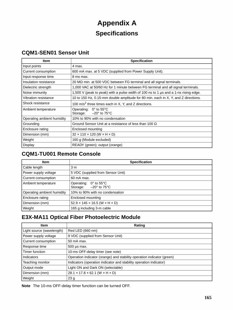
Appendix ASpecifications
CQM1-SEN01 Sensor Unit
CQM1-TU001 Remote Console
E3X-MA11 Optical Fiber Photoelectric Module
Note The 10-ms OFF-delay timer function can be turned OFF.
Item Specification
Input points 4 max.
Current consumption 600 mA max. at 5 VDC (supplied from Power Supply Unit).
Input response time 8 ms max.
Insulation resistance 20 MΩ min. at 500 VDC between FG terminal and all signal terminals.
Dielectric strength 1,000 VAC at 50/60 Hz for 1 minute between FG terminal and all signal terminals.
Noise immunity 1,500 V (peak to peak) with a pulse width of 100 ns to 1 µs and a 1-ns rising edge.
Vibration resistance 10 to 150 Hz, 0.15-mm double amplitude for 80 min. each in X, Y, and Z directions.
Shock resistance 100 m/s2 three times each in X, Y, and Z directions.
Ambient temperature Operating: 0° to 55°CStorage: –20° to 75°C
Operating ambient humidity 10% to 90% with no condensation
Grounding Ground Sensor Unit at a resistance of less than 100 ΩEnclosure rating Enclosed mounting
Dimension (mm) 32 × 110 × 120 (W × H × D)
Weight 160 g (Module excluded)
Display READY (green); output (orange)
Item Specification
Cable length 3 m
Power supply voltage 5 VDC (supplied from Sensor Unit)
Current consumption 60 mA max.
Ambient temperature Operating: 0° to 55°CStorage: –20° to 75°C
Operating ambient humidity 10% to 90% with no condensation
Enclosure rating Enclosed mounting
Dimension (mm) 52.9 × 145 × 16.5 (W × H × D)
Weight 165 g including 3-m cable
Item Rating
Light source (wavelength) Red LED (660 nm)
Power supply voltage 9 VDC (supplied from Sensor Unit)
Current consumption 50 mA max.
Response time 500 µs max.
Timer function 10-ms OFF-delay timer (see note)
Indicators Operation indicator (orange) and stability operation indicator (green)
Teaching monitor Indicators (operation indicator and stability operation indicator)
Output mode Light ON and Dark ON (selectable)
Dimension (mm) 28.1 × 17.8 × 62.1 (W × H × D)
Weight 23 g
165

Specifications Appendix A
E3C-MA11 Photoelectric Module
Note The 10-ms OFF-delay timer function can be turned OFF.
E2C-MA11 Proximity Sensor Module
Note 1. Perform positioning teaching within the stable sensing range. Even if teaching is performed success-fully outside the stable sensing range, the E2C-MA11 in operation may not reset properly. Further-more, even if teaching is performed successfully with or without a sensing object, the E2C-MA11 maynot reset properly after a delicate change is detected.
2. With no surrounding metal or background objects.
3. Off-delay timer can also be turned off with a switch.
Item Rating
Power supply voltage 9 VDC (supplied from Sensor Unit)
Current consumption 50 mA max.
Response time 1.5 ms max.
Timer function 10-ms OFF-delay timer (see note)
Indicators Operation indicator (orange) and stability operation indicator (green)
Teaching monitor Indicators (operation indicator and stability operation indicator are used)
Output mode Light ON and Dark ON (selectable)
Dimension (mm) 28.1 × 17.8 × 62.1 (W × H × D)
Weight 26 g
Item Rating
Power supply voltage 9 VDC (supplied from Sensor Unit)
Current consumption 50 mA max.
Sensing dis-tance adjust-ment range (see note 1)
Setting for Teaching without Sensing Object (see note 2)
E2C-CR5B E2C-CR8AE2C-CR8B
E2C-X1AE2C-C1A
E2C-X1R5A
0.45 mm min. 0.72 mm min. 0.9 mm min. 1.35 mm min.
Setting for Teaching with Sensing Object and Teaching for Posi-tion Control
0.1 to 0.7 mm 0.16 to 1.2 mm 0.2 to 1.5 mm 0.3 to 2 mm
Temperature influence ±25% max. of sensing distance at 23°C between 0 and 55°C
±10% max. of sensing distance at 23°C between 0 and 55°C
Differential travel 15% max. of rated sensing distance
10% max. of rated sensing distance
Response delay Refer to the response frequency for the proximity sensor
Output type NO (ON when sensing object detected)
Timer functions Off-delay timer fixed at 10 ms (see note 3)
Cable length compensation Mode set via four ganged switches
Indicators Operation indicator (orange) and stability indicator (green)
Teaching monitor Indicator (orange/green indicator: operation, using stability indicator)
Dimension (mm) 28.1 × 17.8 × 62.1 (W × H × D)
Weight 26 g
166

Specifications Appendix A
Dimensions
CQM1-SEN01 Sensor Unit
CQM1-TU001 Remote Console
110
3
3
32 120
35.4
4.5
8.5
7
16.552.9
145
15
3,000
42
40
10.2 dia.12 dia.
Module selector
Stability opera-tion indicator
Operation indicator
Teaching indicator
Mode setting selector
Teaching button
167

Specifications Appendix A
E3X-MA11 Optical Fiber Photoelectric Module
E3C-MA11 Photoelectric Module
E2C-MA11 Proximity Sensor Module
26.5 60
28.1
17.8
Fiber lock lever
Stability operation indicator
Operation indicator
Teaching button
Mode setting selector
Operation mode selector
Timer selector2.1
Operation indicator
28.1
26.5
17.8
60
2.1
Four, M2.6 x 6
Stability operation indicator
Teaching button
Mode setting selector
Timer selectorOperation mode selector
Operation indicator
28.1
26.5
17.8
60
2.1
Four, M2.6 x 6
Stability operation indicator
Teaching button
Mode setting selectorTimer selector Code length
selector
168

Specifications Appendix A
Sensor SpecificationsThe following table lists combinations of typical sensors that can be used in combination with each sensormodule.
E3X-MA11
Note 1. Values in parentheses are possible if the E39-F1 Lens Unit is used.
2. The sensing distances of the E32T16 with slits are as follows:0.5-mm wide slit: 450 mm with a minimum sensing object size of 0.2 mm dia.; 1.0-mm slit: 800 mmwith a minimum sensing object size of 0.3 mm dia.
3. The E32-T51 can be used continuously within a temperature range of –40° to 130°C.
Item Sensing method
Thru-beam model Side view thru-beam
model
Heat-resistive thru-beam
model
Screen thru-beam model
Feature Long sensing distance
Standard sensing distance
Flexible cable Long sensing distance
Resisting 150°C
Sensing a width of 10
mm
Model E32-T11L E32-TC200 E32-T11 E32-T14L E32-T51 E32-T16
Sensing distance (standard sensing object)
500 mm (1,200 mm) (see note 1) (1.4 dia. mm min. non-trans-parent object)
270 mm (2,000 mm) (see note 1) (1 dia. mm min. non-transparent object)
240 mm (1,300 mm) (see note 1) (1 dia. mm min. non-transparent object)
130 mm (1 dia. mm min. non-transpar-ent object)
300 mm (1.5 dia. mm min. non-trans-parent object)
1,000 mm (see note 2) (view: 10 mm wide) (10 dia. mm min. non-transparent object)
Minimum sensing object (non-trans-parent object)
0.2 dia. mm 0.3 dia. mm 0.4 dia. mm 0.2 dia. mm (see note 2)
Ambient operating temperature
–40° to 70°C with no icing –40° to 150°C with no icing (see note 3)
–40° to 70°C with no icing
Ambient operating humidity
35% to 85%
Permissible bending radius
25 mm min. 4 mm min. 25 mm min. 35 mm min. 25 mm min.
Cable covering Black polyethylene Vinyl chloride Black polyeth-ylene
Fluorocarbon resin
Black polyeth-ylene
Enclosure rating IEC IP67
169

Specifications Appendix A
Note The E32-D51 can be used continuously within a temperature range of –40° to 130°C.
Item Sensing method
Reflective model Side view reflective
model
Heat-resistive reflective
model
Retroreflec-tive model
Feature Long sensing distance
Standard sensing distance
Flexible cable Long sensing distance
Resisting 150°C
Sensing a transparent
object
Model E32-D11L E32-DC200 E32-D11 E32-D14L E32-D51 E32-R21 and E39-R3
Sensing distance (standard sensing object)
White paper
150 mm (20 × 20 cm)
100 mm (10 × 10 cm)
60 mm (10 × 10 cm)
40 mm (5 × 5 cm)
60 mm (10 × 10 cm)
25 to 250 mm (35 dia. mm min. non-transparent object)
Black paper
50 mm (20 × 20 cm)
20 mm (10 × 10 cm)
15 mm (10 × 10 cm)
8 mm (5 × 5 cm)
12 mm (10 × 10 cm)
---
Minimum sensing object (pure copper wire)
0.015 dia. mm 0.03 dia. mm 0.6 dia. mm
Differential distance 20% max. of the sensing distance
Ambient operating temperature
–40° to 70°C with no icing –40° to 150°C with no icing (see note)
–40° to 70°C with no icing
Ambient operating humidity
35% to 85%
Permissible bending radius
25 mm min. 4 mm min. 25 mm min. 35 mm min. 25 mm min.
Cable covering Black polyethylene vinyl chloride Black polyeth-ylene
Fluorocarbon resin
Black polyeth-ylene
Enclosure rating IEC IP67 IEC IP67
170

Specifications Appendix A
E3C-MA11Item Thru-beam model Diffuse
reflective model
Limited reflective model
E3C-S10 E3C-1 E3C-2 E3C-DS5W E3C-DS10 E3C-LS3R
Sensing distance 10 cm 1 m 2 m 5 cm 10 cm 3 ± 0.3 cm
Minimum sensing object 2-mm non-transparent object
4-mm non-transparent object
8-mm non-transparent object
---
Standard sensing object --- 10 × 10 cm white paper
5 × 5 cm white paper
1 × 1 cm white paper
Directional angle 10° to 60° 3° to 20° 3° to 15° ---
Differential distance --- 20% max. 10% max. ±3% max.
Ambient operating illumination
Incandes-cent lamp
3,000 lux max. on the surface of each sensing object 1,000 lux max.
Sunlight 10,000 lux max. on the surface of each sensing object 3,000 lux max.
Ambient operating tempera-ture
–25° to 70°C with no icing
Ambient operating humidity 35% to 85%
Vibration resistance 10 to 55 Hz, 1.5-mm double amplitude in X, Y, and Z directions for 2 hours each
10 to 500 Hz, 1.5-mm dou-ble ampli-tude in X, Y, and Z direc-tions for 2 hours each
10 to 55 Hz, 1.5-mm double amplitude in X, Y, and Z directions for 2 hours each
Shock resistance 500 m/s2 3 times each in X, Y, and Z directions
Enclosure rating IEC IP64 (drip proof)
IEC IP66 (water resistive) IEC IP50 IEC IP64 (drip proof)
Item Reflective model for mark detection
E3C-VS1G E3C-VS3R E3C-VM35R E3C-VS7R
Sensing distance 1 ± 0.2 cm 3 ± 0.5 cm 3.5 ± 0.5 cm 7 ± 1.0 cm
Minimum sensing mark (black mark on white paper)
0.9 mm at the center of the sensing distance
1.6 mm at the center of the sensing distance
0.2 mm at the center of the sensing distance
0.6 mm at the center of the sensing distance
Ambient operating illumination
Incandescent lamp
1,000 lux max. on the surface of each sensing object.
Sunlight 3,000 lux max. on the surface of each sensing object
Ambient operating temperature –10° to 70°C with no icing –25° to 70°C with no icing
–10° to 70°C with no icing
Ambient operating humidity 35% to 85%
Vibration resistance 10 to 55 Hz, 1.5-mm double amplitude in X, Y, and Z directions for 2 hours each
Shock resistance 500 m/s2
Enclosure rating IEC IP64 (drip proof) IEC IP50 (drip proof)
171

Specifications Appendix A
Model Suggested cable Substitute cable
Thru-beam model
E3C-S10E3C-1E3C-2
Reflective model
E3C-DS10E3C-VS1GE3C-VS3R
E3C-LS3R
If the shielded parallel cable with vinyl insula-tion is not available, use two single-conductor shielded vinyl cables.
Reflective model
E3C-DS5WE3C-VS7RE3C-VM35R
If the shielded parallel cable with vinyl insula-tion is not available, use two single-conductor shielded vinyl cables.
Shielded round cable with polyethylene insulation
2.4 dia.
Shield
White (polyethylene)
12-strand wire/0.18 dia.
A single shielded cable, with vinyl insulation, and conductor with a cross section of 0.3 mm2 min.
Gray (vinyl sheath)
White (vinyl)
Shield
Shielded parallel cable with vinyl insulation
2.4
4.3
Internal sheath
Sheath
Polyethylene
Conductor
Shield
12-strand wire/0.18 dia.
Shielded parallel cable with vinyl insulation
7-strand wire/0.18 dia.
Sheath
Shield
Polyethylene
Conductor
172
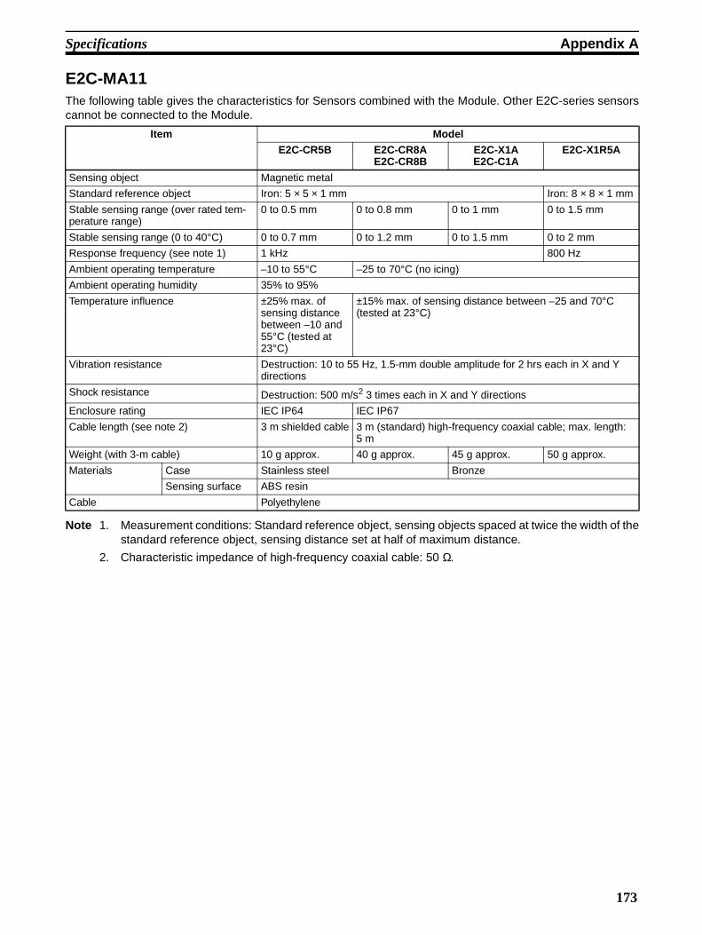
Specifications Appendix A
E2C-MA11The following table gives the characteristics for Sensors combined with the Module. Other E2C-series sensorscannot be connected to the Module.
Note 1. Measurement conditions: Standard reference object, sensing objects spaced at twice the width of thestandard reference object, sensing distance set at half of maximum distance.
2. Characteristic impedance of high-frequency coaxial cable: 50 Ω.
Item Model
E2C-CR5B E2C-CR8AE2C-CR8B
E2C-X1AE2C-C1A
E2C-X1R5A
Sensing object Magnetic metal
Standard reference object Iron: 5 × 5 × 1 mm Iron: 8 × 8 × 1 mm
Stable sensing range (over rated tem-perature range)
0 to 0.5 mm 0 to 0.8 mm 0 to 1 mm 0 to 1.5 mm
Stable sensing range (0 to 40°C) 0 to 0.7 mm 0 to 1.2 mm 0 to 1.5 mm 0 to 2 mm
Response frequency (see note 1) 1 kHz 800 Hz
Ambient operating temperature –10 to 55°C –25 to 70°C (no icing)
Ambient operating humidity 35% to 95%
Temperature influence ±25% max. of sensing distance between –10 and 55°C (tested at 23°C)
±15% max. of sensing distance between –25 and 70°C (tested at 23°C)
Vibration resistance Destruction: 10 to 55 Hz, 1.5-mm double amplitude for 2 hrs each in X and Y directions
Shock resistance Destruction: 500 m/s2 3 times each in X and Y directions
Enclosure rating IEC IP64 IEC IP67
Cable length (see note 2) 3 m shielded cable 3 m (standard) high-frequency coaxial cable; max. length: 5 m
Weight (with 3-m cable) 10 g approx. 40 g approx. 45 g approx. 50 g approx.
Materials Case Stainless steel Bronze
Sensing surface ABS resin
Cable Polyethylene
173


PART VIILinear Sensor Interface Units
CQM1-LSE01CQM1-LSE02
175


SECTION 1Features and System Configuration
This section provides the features and system configuration relating to the Linear Sensor Interface Unit.
1-1 Features . . . . . . . . . . . . . . . . . . . . . . . . . . . . . . . . . . . . . . . . . . . . . . . . . . . . . . 178
1-2 System Configuration . . . . . . . . . . . . . . . . . . . . . . . . . . . . . . . . . . . . . . . . . . . 179
177

Features Section 1-1
1-1 Features• When the Linear Sensor Interface Unit is used in a system, linear sensor
input signals received by the Unit are converted into appropriate numericvalues according to preset scaling values.
• The Linear Sensor Interface Unit compares the scaled conversion datawith the four comparison set values (HH, H, L, and LL), ensuring the easeof object discrimination.
• The four timing hold modes that are synchronized with the external signalinput allow free setting of the input data sampling point and easy retrievalor control of desired data.
• The CQM1-LSE02 can convert input data into voltage output, which canbe used as data for external monitoring.
• The teaching function enables the Linear Sensor Interface Unit to useactual input as scaling and comparison set values, thus ensuring the easyadjustment.
• The zero point (measurement standard point) can be forced, which allowsrelative object measurement.
• A ladder program can be used to enable the CQM1-LSE02 to have volt-age output. The ladder program used with the CQM1-LSE02 enables theoutput voltage to correspond to the data.
• The Programming Console can be used to easily set the Linear SensorInterface Unit to its initial values.
Linear Sensor Interface Units Model Type
CQM1-LSE01 Standard
CQM1-LSE02 With monitor output
178

System Configuration Section 1-2
1-2 System Configuration
• Use the Programming Console to write its initial values to the Unit.
• The Unit needs zero input and zero reset input for forced zero.
• The CQM1-LSE01 does not have monitor output.
Word Number The word allocations for a CQM1H/CQM1-series Dedicated I/O Unit are asfollows.
Input: 001 to 015Output: 100 to 115
The Unit uses a single input word and single output word. The CQM1-LSE01,which is not provided with the monitor output function, also uses a single out-put word.
Words are allocated in left-to-right order to the CQM1H/CQM1-series Dedi-cated I/O Units mounted to the PC. For example, if an Input Unit that occupiesone word, an Output Unit that occupies two words, and the CQM1-LSE01/LSE02 are mounted to the PC and if the Input Unit and Output Unit arelocated to the left of the CQM1-LSE01/LSE02, the input and output wordnumbers of the CQM1-LSE01/LSE02 will be 002 and 102 respectively.
Power Supply CQM1H/CQM1-series CPU
Linear Sensor Interface
Other Units
Sensor input(V INPUT/I INPUT)
Timing input (T/G)
Monitor output (OUTPUT)
to
to
Input word
Output word
Input Unit located on the left side
CPU
Output Unit located on the left side
CQM1-LSE01/LSE02
179


SECTION 2Functions
This section provides an explanation of the scaling, timing hold, data input, teaching, forced zero, and monitor outputfunctions.
2-1 Scaling. . . . . . . . . . . . . . . . . . . . . . . . . . . . . . . . . . . . . . . . . . . . . . . . . . . . . . . 182
2-2 Timing Hold . . . . . . . . . . . . . . . . . . . . . . . . . . . . . . . . . . . . . . . . . . . . . . . . . . 183
2-3 Scaled Conversion Data/Comparison Result . . . . . . . . . . . . . . . . . . . . . . . . . 186
2-4 Teaching . . . . . . . . . . . . . . . . . . . . . . . . . . . . . . . . . . . . . . . . . . . . . . . . . . . . . 187
2-5 Forced Zero (Zero-shift) . . . . . . . . . . . . . . . . . . . . . . . . . . . . . . . . . . . . . . . . . 188
2-6 Voltage Monitor Output . . . . . . . . . . . . . . . . . . . . . . . . . . . . . . . . . . . . . . . . . 188
181

Scaling Section 2-1
2-1 ScalingThe conversion of input voltage or current in a certain range to a value in acertain range is called scaling. For example, if the user converts input voltageor current so to be displayed as a percentage, the converted value will be dis-played in the range 0 through 100. The following is the scaling method.
The following graph shows the relationship between input to the Unit and thevalues converted from the input. In this graph, Y1 is converted data corre-sponding to input data X1 and Y2 is a converted data corresponding to inputdata X2.
As shown in the above graph, it is possible to obtain scaled conversion data(Y) corresponding to input data (X).
Example for Measuring Lengths Using a Sensor with an Input of 4 to 20 mA
If the output of the sensor is 4 mA when the length of the object sensed by thesensor is 10 centimeters and the output of the sensor is 15 mA when thelength of the object is 30 centimeters, the following data should be input.
X1 = 400, X2 = 1500, Y1 = 1000, Y2 = 3000
If the input from the sensor is 10 mA, a value corresponding to the input willbe 2091 (i.e., 20.91 centimeters) in this case.
X1 can be larger or smaller than X2. Therefore, Y1 can be larger or smallerthan Y2.
Scaled conversion data
Input
182

Timing Hold Section 2-2
Reference When scaling is conducted, the scaled conversion data may exceed the rangebetween 9999 and –9999 even if the input values are within the permissiblerange. The scaled conversion data that fall outside the permissible measure-ment range are treated as overflow values. The input values that fall outsidethe permissible range (over-range) are also treated as overflow values.
2-2 Timing HoldThe Unit takes samplings of input values that are input from the linear sensor,computes them, and then holds the computed values. Any of the following tim-ing hold types can be selected for the Unit.
• Normal
• Sampling hold
• Maximum hold
• Minimum hold
• Peak-to-peak hold
Normal If the timing hold is set to normal, the TIMING input is not effective, and theUnit continues sampling. The reset input is not effective.
Sampling Hold If the timing hold is set to sampling hold, the Unit samples the data at the ris-ing edge of the timing input to the Unit when the TIMING input is turned ON.
The Unit stops data sampling during the following periods. The data is“BBBB.”
[1] From the moment the Unit is turned ON until the first TIMING input isturned ON.
9999
−9999
Lower limit
Scaled conversion data
Upper limit
Input
Permissible measurement range
Overflow
183

Timing Hold Section 2-2
[2] From the moment the reset input is turned ON until the TIMING input isturned ON for the first time after the reset input is turned OFF.
Maximum Hold If the timing hold mode is set to maximum hold, the Unit continues data sam-pling while the TIMING input is ON.
• When the TIMING input is turned OFF and the measurement mode isselected using the data input function, the maximum value of the inputdata sampled between the leading and trailing edge of the timing input isstored in the input word as the scaled conversion data.
• When the TIMING input is turned OFF and the comparison mode isselected using the data input function, the comparison result flags of theinput word are turned ON or OFF according to the comparison result pro-cessed by the Unit.
The Unit stops data sampling during the following periods, The scaled conver-sion data is “BBBB.”[1] From the moment the Unit is turned ON until the first timing input is turned
ON and OFF.[2] From the moment the reset input is turned ON until the timing input is ON
and OFF for the first time after the reset input is turned OFF.
Minimum Hold If the timing hold mode is set to minimum hold, the Unit continues data sam-pling while the TIMING input is ON.
• When the TIMING input is turned OFF and the measurement mode isselected using the data input function, the minimum value of the inputdata sampled between the leading and trailing edge of the timing input isstored in the input word as the scaled conversion data.
• When the TIMING input is turned OFF and the comparison mode isselected using the data input function, the comparison result flags of theinput word are turned ON or OFF according to the comparison result pro-cessed by the Unit.
The Unit stops data sampling during the following periods, The scaled conver-sion data is “BBBB.”
TIMING input
Reset input
Power on
Input
Scaled conver-sion data[2][1]
TIMING input
Reset input
Power on
Input
Sensing sectionScaled conver-sion data[2][1]
184

Timing Hold Section 2-2
[1] From the moment the Unit is turned ON until the first timing input is turnedON and OFF.
[2] From the moment the reset input is turned ON until the timing input is ONand OFF for the first time after the reset input is turned OFF.
Peak-to-peak Hold If the timing hold mode is set to peak-to-peak hold, the Unit continues datasampling while the TIMING input is ON.
• When the TIMING input is turned OFF and the measurement mode isselected using the data input function, the difference between the maxi-mum value and minimum value of the input data sampled between theleading and trailing edge of the timing input is stored in the input word asthe scaled conversion data.
• When the TIMING input is turned OFF and the comparison mode isselected using the data input function, the comparison result flags of theinput word are turned ON or OFF according to the comparison result pro-cessed by the Unit.
The Unit stops data sampling during the following periods, The scaled conver-sion data is “BBBB.”
[1] From the moment the Unit is turned ON until the first timing input is turnedON and OFF.
[2] From the moment the reset input is turned ON until the timing input is ONand OFF for the first time after the reset input is turned OFF.
Available Commands and Functions
Power onSensing section Scaled conver-
sion data
Input
TIMING input
Reset input
[2][1]
Power onSensing section
Scaled con-version data
Input
TIMING input
Reset input
b–ac–d
[2][1]
Function (Command code) Timing HoldNormal Sampling Hold Maximum Hold Minimum Hold Peak-to-peak
HoldScaling Value Teach (C5*0) Yes Command Error (Word status: E003)Set Value Teach (C8*0) YesPresent Value Read: BCD (CC00) Yes
185

Scaled Conversion Data/Comparison Result Section 2-3
2-3 Scaled Conversion Data/Comparison ResultEither of the following is stored in the input word.
• Scaled conversion data• Result of comparison between the set value and the scaled conversion
data
Scaled Conversion Data The binary-coded scaled conversion data is stored in the input word allocatedto the Unit.
Comparison Results The comparison result of the value is obtained by comparing the preset HH,H, L, and LL comparison set values and the scaled conversion data. The fol-lowing bits will be turned ON according to the result.
• HH: The HH bit of the input word will be ON if the present scaled conver-sion data equals or is greater than the HH set value.
• H: The H bit of the input word will be ON if the present scaled conversiondata equals or is greater than the H set value.
• L: The L bit of the input word will be ON if the present scaled conversiondata equals or is less than the L set value.
• LL: The LL bit of the input word will be ON if the present scaled conver-sion data equals or is less than the LL set value.
The PASS bit of the input word will be ON in other cases.If the Unit is in normal hold mode, the hysteresis of the present scaled conver-sion data will be effective when any of the above bits is turned OFF.The following is an example of data comparison. The timing hold is set to nor-mal.
Forced-zero Shift (ZERO external control input)
Yes Yes Yes Yes Zero input will be ignored.
Hysteresis Set (CA00) Hysteresis Read (CB00)
Yes Commands are received, but the hysteresis function is invalid.
Function (Command code) Timing HoldNormal Sampling Hold Maximum Hold Minimum Hold Peak-to-peak
Hold
Comparative set value
Input word
Scaled conversion data
HysteresisHysteresis
186

Teaching Section 2-4
2-4 TeachingThe teaching function is can be set only when the timing hold in operationmode A is set to normal.
The Programming Console makes it possible to adjust the scaling and set val-ues preset on the Unit using objects.
Scaling Value Teach When the scaling value teach command is executed, the actual input valuecan be set as the X1 or X2.This allows an easy adjustment of the input error.For example, when setting the X1 value as an input value of the smallestobject, execute a scaling command while the smallest object is being sam-pled. In the same manner, the X2 value can be set as the largest object inputvalue if the scaling command is executed while the largest object is beingsampled.
Set Value Teaching By using the set value teach command, an actual input value can be set asthe HH, H, L, or LL set value. It is useful for making judgments on whetherproducts are acceptable or defective.For example, when setting the lowest set value LL, execute the set valueteach command while the smallest object is being measured. If the samecommand is executed while the largest object is being measured, the highestset value HH can be set.
Actual size
Sensor input
Smallest object
Adjustment value
X1 value
Smallest object
Sensor input
Adjustment value
Actual size LL set value
187

Forced Zero (Zero-shift) Section 2-5
2-5 Forced Zero (Zero-shift)The forced zero function enables the Unit to shift the scaled conversion datato 0 to calibrate, which allows relative object measurement with ease.The forced zero state stays in effect until ZERO RESET input signal to theUnit is turned ON.
When zero input is turned ON while the Unit is sampling data, the scaled con-version data will be shifted to zero and stored as binary data in the input word,or the comparison result flags of the input word are turned ON or OFF accord-ing to the comparison result processed by the Unit.The nonvolatile memory can store the zero shift value.While the forced-zero state stays in effect, the ZERO indicator is lit.
Note The forced zero function is not effective when the timing hold mode is set topeak-to-peak hold.
2-6 Voltage Monitor OutputThe CQM1-LSE02 has a voltage monitor output function.Scaled conversion data monitor mode or set data D/A output mode can beselected.The Unit refreshes its monitor output at 0.5-s intervals.
Scaled Conversion Data Monitor Mode
In this mode, it is possible to output voltage corresponding to the scaled con-version data.
ZERO input
ZERO RESET input
ZERO indicator
Input
Calibrated scaled conver-sion data
188
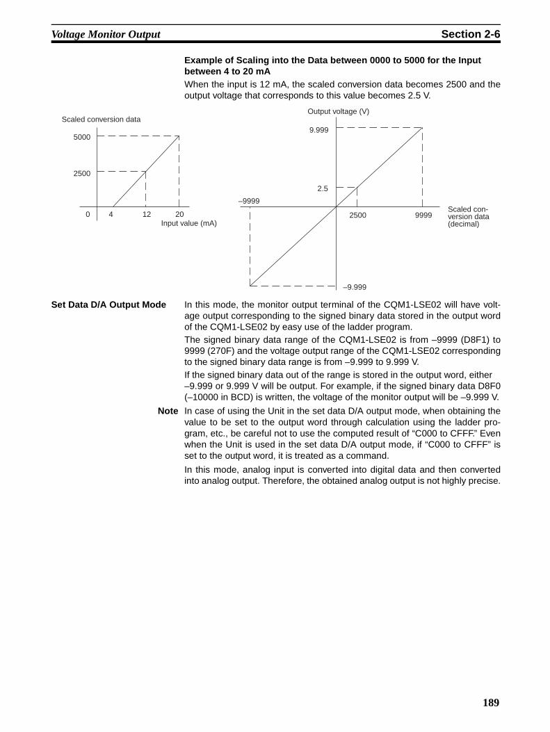
Voltage Monitor Output Section 2-6
Example of Scaling into the Data between 0000 to 5000 for the Input between 4 to 20 mAWhen the input is 12 mA, the scaled conversion data becomes 2500 and theoutput voltage that corresponds to this value becomes 2.5 V.
Set Data D/A Output Mode In this mode, the monitor output terminal of the CQM1-LSE02 will have volt-age output corresponding to the signed binary data stored in the output wordof the CQM1-LSE02 by easy use of the ladder program.The signed binary data range of the CQM1-LSE02 is from –9999 (D8F1) to9999 (270F) and the voltage output range of the CQM1-LSE02 correspondingto the signed binary data range is from –9.999 to 9.999 V.If the signed binary data out of the range is stored in the output word, either –9.999 or 9.999 V will be output. For example, if the signed binary data D8F0(–10000 in BCD) is written, the voltage of the monitor output will be –9.999 V.
Note In case of using the Unit in the set data D/A output mode, when obtaining thevalue to be set to the output word through calculation using the ladder pro-gram, etc., be careful not to use the computed result of “C000 to CFFF.” Evenwhen the Unit is used in the set data D/A output mode, if “C000 to CFFF” isset to the output word, it is treated as a command.
In this mode, analog input is converted into digital data and then convertedinto analog output. Therefore, the obtained analog output is not highly precise.
Scaled conversion data
Input value (mA)0 4 12 20
2500
5000
–9999
–9.999
2500 9999
9.999
2.5
Output voltage (V)
Scaled con-version data (decimal)
189


SECTION 3Nomenclature and Functions
This section provides the nomenclature, and terminal and indicator functions of the Linear Sensor Interface Unit.
3-1 Nomenclature . . . . . . . . . . . . . . . . . . . . . . . . . . . . . . . . . . . . . . . . . . . . . . . . . 192
3-2 Terminals. . . . . . . . . . . . . . . . . . . . . . . . . . . . . . . . . . . . . . . . . . . . . . . . . . . . . 193
191

Nomenclature Section 3-1
3-1 Nomenclature
Front View
Indicators
Side View
Indicators
Name Color Function
RDY Green Lit when the Linear Sensor Interface Unit is ready for use.
ERR Red Lit when an internal error, such as IC malfunctioning, occurs.
BROKEN-WIRE Red Lit when 1- to 5-V or 4- to 20-mA input to the Unit is dis-connected. This indicator cannot be used to detect the disconnection of ±9.999- or ±5-V input.
TIMING/GATE Orange Lit when TIMING or GATE input to the Unit is ON.
ZERO Orange Lit when the forced zero function is effective.
Slide lock
Cover
Terminals
Slide lock
192

Terminals Section 3-2
3-2 Terminals
V INPUT Connect a linear sensor with voltage output to this terminal. The available volt-age ranges of the V INPUT terminal are from –9.999 to 9.999, from –5 to 5,and from 1 to 5 V.
I INPUT Connect a linear sensor with a current output range from 4 to 20 mA to thisterminal.
COM Common terminal for the V INPUT and I INPUT terminals.
OUTPUT Monitor output terminal for the CQM1-LSE02.
T/G Timing input terminal. If the timing hold is set to sampling hold, the Unit will bein data sampling operation at the moment timing input is turned ON. If the tim-ing hold is set to maximum hold, minimum hold, or peak-to-peak hold, the Unitwill be in data sampling operation while timing input is ON. This terminal is notused by if the timing hold is set to normal.
RES Reset input terminal. When reset input is turned ON, the Unit will no longer bein HOLD mode. This terminal is used if the Unit is set to any timing hold otherthan normal.
ZERO Zero input terminal. When zero input is turned ON, the Unit will forcibly shiftthe scaled conversion data to zero and the Unit will continue operating.
ZRES Zero reset terminal. The forced-zero state is canceled when zero reset inputturned ON.
!Caution Do not use the unused terminals for relaying signals.
–
+
–+
+
–
+24 VDC
+24 VDC
193


SECTION 4Connections
This section describes the connections of the Linear Sensor Interface Unit.
4-1 Mounting and Wiring . . . . . . . . . . . . . . . . . . . . . . . . . . . . . . . . . . . . . . . . . . . 196
195

Mounting and Wiring Section 4-1
4-1 Mounting and WiringMounting Refer to the CQM1H Operation Manual (W363) or the CQM1 Operation Man-
ual (W226) before mounting this Unit to the PC.
Wiring Refer to 3-2 Terminals for the wiring of the terminals.
!Caution
• Make sure that the polarity of each input line connecting to the terminalsis correct.
• It is possible that the terminal block may become disconnected from theUnit. After the terminals are wired, make sure that the terminal block isproperly connected to the Unit.
Connection Terminals Connect each input line to the terminal using a solderless terminal.
Do not tighten any screw of the terminals to a torque exceeding 0.5 N • m.
Use either of the following types of M3 solderless terminals for the input linesconnecting to the terminals.
Crimp Connectors Crimp connectors for wiring should be less than 6.2 mm wide (M3), and the
wire should be AWG22 to 18 (0.25 to 1.65 mm2).
6.2 mm max.
6.2 mm max.
196
SECTION 5Basic Operation
This section describes the basic operation of the Linear Sensor Interface Unit using the Programming Console.
5-1 Operating Method . . . . . . . . . . . . . . . . . . . . . . . . . . . . . . . . . . . . . . . . . . . . . . 198
5-2 Programming Console Operation . . . . . . . . . . . . . . . . . . . . . . . . . . . . . . . . . . 199
5-3 Operation Mode . . . . . . . . . . . . . . . . . . . . . . . . . . . . . . . . . . . . . . . . . . . . . . . 200
5-4 Scaling. . . . . . . . . . . . . . . . . . . . . . . . . . . . . . . . . . . . . . . . . . . . . . . . . . . . . . . 202
5-5 Comparison . . . . . . . . . . . . . . . . . . . . . . . . . . . . . . . . . . . . . . . . . . . . . . . . . . . 205
5-6 Monitoring . . . . . . . . . . . . . . . . . . . . . . . . . . . . . . . . . . . . . . . . . . . . . . . . . . . 207
197

Operating Method Section 5-1
5-1 Operating Method
Initial Parameter Settings Use the Programming Console to write the initial parameters to the outputword of the Unit.
1,2,3... 1. Execute the operation mode A set command or operation mode B set com-mand to determine the operation mode.
2. Determine the scaling values.
3. Determine the set values if the Unit is used in comparison mode.
4. Execute the operation mode A set command to determine the hysteresis ifthe timing hold type is set to normal.
Monitoring Use a ladder program to retrieve the input word data for monitoring. The inputword data is the scaled conversion data if the Unit is in measurement mode.The input word data is a comparison result if the Unit is in comparison mode.
Note The scaling values and zero shift value will be reset to the factory-set values.if the input type is changed with the operation mode A set command. Be sureto set the scaling values and zero shift value properly after the input type ischanged with the operation mode A set command.The command operation examples in the following section are described onthe condition that the output word state before and after command operationbe set to “0000.” It must be noted that, if the Unit is used in the set data D/A output mode, theoutput is specified to be 0 V. Therefore, set a desired output value instead of“0000” in actual operation.
Set the operation mode.
Set the scaling values.
Set the set values.
Set the hysteresis.
End
Is the Unit in comparison
mode?
Is the Unit in normal hold
mode?
Initial parameter settings
N
Y
N
Y
Monitoring
198

Programming Console Operation Section 5-2
5-2 Programming Console OperationRefer to the CQM1H Operation Manual (W363) or the CQM1 Operation Man-ual (W226) for the detailed operating method of the Programming Console.
The operation of the Programming Console required for the initial settings isexplained below.
Initial Screen Operate the Programming Console as described below so that the defaultscreen of the Programming Console in program mode will appear.
1,2,3... 1. Connect the Programming Console to the CQM1H/CQM1 CPU, set themode selector of the Programming Console to PROGRAM MODE, andsupply power to the Programming Console.
2. Input the password.
3. The default screen will appear.
I/O Words The contents of the I/O words will appear on the screen of the ProgrammingConsole. When measured mode is selected for data input, the present binary-coded scaled conversion data will appear under the input word display.
1,2,3... 1. The input word (word 001 in this example) will be displayed.
2. The output word (word 100 in this example) will be displayed.
Command The command codes can be set to output word. In this example, descriptionsare given for the operation mode A.
1,2,3... 1. The command code is set to the output word. The response for the com-mand will appear under the input word display.
CLR MONTR
CLR
SHIFT
CH A0
A0
B1 MONTR
SHIFT
CH B1
A0
A0 MONTR
Output word Input word
CHG SHIFTC
2
CA
0A
0A
0 WRITE
199

Operation Mode Section 5-3
2. If any parameter is used, the contents of the output word will be replacedwith the parameter. The response to the parameter will appear under theinput word display.
5-3 Operation ModeSettings The operation mode is selected with the operation mode A set command or
operation mode B set command.
The following four items can be selected for the Unit with the operation modeA set command.
• Data InputMeasurement Mode or Comparison Mode:When the Unit is in measurement mode, the binary-coded scaled conver-sion data is stored in the input word allocated to the Unit. When the Unit isin comparison mode, the Comparison Result Flags of the input word allo-cated to the Unit are turned ON or OFF after comparing the set value andscaled conversion data. When any overrange or sensor disconnection isdetected by the Unit, the Overrange or Sensor Disconnection Flag of theinput word is turned ON. The measurement mode is the factory setting.
• Timing HoldNormal, Sampling Hold, Maximum Hold, Minimum Hold, Peak-to-peak Hold:When setting the initial values, one of the five timing holds can beselected for the Unit. The timing hold is factory-set to normal.
• Input Type±9.999 V, ±5 V, 1 to 5 V, or 4 to 20 mA:When setting the initial values, any input type among four input types canbe selected for the Unit. The ±9.999 V input type is the factory setting.
• Monitor Output (CQM1-LSE02 Only)Scaled Conversion Data Monitor Mode or Set Data D/A Output Mode:The CQM1-LSE02 has a monitor output terminal, to which simple moni-toring devices, such as the K3TE Digital Panel Meter, can be connected.In the scaled conversion data monitor mode, the Unit outputs the voltagecorresponding to the scaled conversion data. In the set data D/A outputmode, the monitor output terminal has voltage output corresponding tothe data which is written to the output word allocated to the Unit. Thescaled conversion data monitor mode is the factory setting.
It is possible to select any of the following three items for the Unit with theoperation mode B set command.
• Input Sampling SpeedFast or Slow:The sampling time and period can be set to fast or slow according to thetype of sensing object considering the relationship between the measur-ing accuracy and measuring speed. The sampling time/period is factory-set to slow.
• Number of Averaging Process Times1, 2, 4, 8, or 16:For more precise sampling, it is possible to take an average of a desig-nated number of samples. The number is factory-set to 4.
CHGC
2C
2D
3D
3B
1 WRITE
200
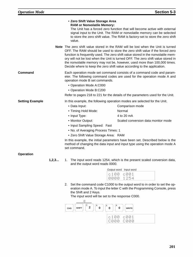
Operation Mode Section 5-3
• Zero Shift Value Storage AreaRAM or Nonvolatile Memory:The Unit has a forced zero function that will become active with externalsignal input to the Unit. The RAM or nonvolatile memory can be selectedto store the zero shift value. The RAM is factory-set to store the zero shiftvalue.
Note The zero shift value stored in the RAM will be lost when the Unit is turnedOFF. The RAM should be used to store the zero shift value if the forced zerofunction is frequently used. The zero shift value stored in the nonvolatile mem-ory will not be lost when the Unit is turned OFF. The zero shift value stored inthe nonvolatile memory may not be, however, used more than 100,000 times.Decide where to keep the zero shift value according to the application.
Command Each operation mode set command consists of a command code and param-eter. The following command codes are used for the operation mode A andoperation mode B set commands.
• Operation Mode A:C000
• Operation Mode B:C200
Refer to pages 218 to 221 for the details of the parameters used for the Unit.
Setting Example In this example, the following operation modes are selected for the Unit.
• Data Input: Comparison mode
• Timing Hold Mode: Normal
• Input Type: 4 to 20 mA
• Monitor Output: Scaled conversion data monitor mode
• Input Sampling Speed: Fast
• No. of Averaging Process Times: 1
• Zero Shift Value Storage Area: RAM
In this example, the initial parameters have been set. Described below is themethod of changing the data input and input type using the operation mode Aset command.
Operation
1,2,3... 1. The input word reads 1254, which is the present scaled conversion data,and the output word reads 0000.
2. Set the command code C1000 to the output word to in order to set the op-eration mode A. To input the letter C with the Programming Console, pressthe Shift and 2 Keys.The input word will be set to the response C000.
Output word Input word
CHG SHIFTC
2
C
A0
A0
A0 WRITE
201

Scaling Section 5-4
3. Set 2040 to the output word. The Unit will be in comparison mode and theavailable input range will be from 4 to 20 mA. All the other modes will re-main unchanged.
4. When the Unit correctly receives the command, the input word will be setto 2040.
5. Reset 0000 to the output word.
6. The Comparison Result Flags of the input word is turned ON or OFF. In thisexample, the input word is set to 0004 (PASS).
5-4 ScalingThe setting method of the scaling values is explained below. Refer to 6-1 Scal-ing Value Teaching for the method to obtain the scaling values from the teach-ing operation.
Settings Scales input values into desired values within a range from –9999 to 9999. X2– Y2 and X1 – Y1 must be input (X: input value, Y: corresponding displaydata). The X1 value must be different from the X2 value, otherwise the Unitwill process them as an overrange value of B000.
Default Values The following are the factory-set scaling values.
X1: 0X2: 1000Y1: 0Y2: 1000
Therefore, if the Unit is operated with the factory-set scaling values with aninput range from 4 to 20 mA, an input of 4 mA will be regarded as 400 and aninput of 20 mA will be regarded as 2000. When the input type is “1 to 5 V,” aninput of 1 V will be 1000 and that of 5V will be 5000. When the input type is “–9999 to 9999 V,” an input of 9,999 V will be 9999 and that of –9999 V will be–9999.
CHGC
2A
0E
4A
0 WRITE
CHGA
0A
0A
0A
0 WRITE
Input value
Display data
202

Scaling Section 5-4
The graph below shows the relationship between the actual input values andthe internal data.
Command The scaling value set command consists of a command code and parameter.The following command codes are used to set the X1, X2, Y1, and Y2 scalingvalues.
• X1 Scaling Value Set: C40@• X2 Scaling Value Set: C41@• Y1 Scaling Value Set: C42@• Y2 Scaling Value Set: C43@
Each of the above scaling values has the suffix @, which should be replacedwith 0 if the value is positive and F if the value is negative when they are input.The parameter range of each of the above scaling values is 0000 to 9999.
Refer to page 222 for the details of the scaling value set command.
Setting Example In this example, the following scaling values are selected for the Unit.
X1: 400X2: 2000Y1: 0000Y2: 1000
This means an input of 4 to 20 mA is scaled to binary data of “0 to 1000” andthen converted into percentage data to the first decimal place.
In this example, the factory-set operation mode and scaling values have beenset.
Operation
1,2,3... 1. The input word reads 1254, which is the present scaled conversion data,and the output word reads 0000.
Input–9.999 V –5 V
(–5000)
(–9999)
(400)(1000)
(2000)
(5000)
(9999)
Output word Input word
203

Scaling Section 5-4
2. Set the command code C400 for the X1 value. To input the letter C with theProgramming Console, press the Shift and 2 Keys. The input word will beset to the response C400.
3. Set 0400 to the output word.
4. When the Unit correctly receives the command, the input word will be setto 0400.
5. Input the command code C410 for the X2 value. The input word will be setto the response C410.
6. Set 2000 to the output word.
7. When the Unit correctly receives the command, the input word will be setto 2000.
8. Set 0000 for the Y1 value and 1000 for the Y2 value using the above meth-od.
CHG SHIFTC
2
C
E4
A0
A0 WRITE
CHGA
0E
4A
0A
0 WRITE
CHG SHIFTC
2
C
E4
B1
A0 WRITE
CHGC
2A
0A
0A
0 WRITE
CHG SHIFT
C
C2
E4
C2
A0 WRITE
CHGA
0A
0A
0A
0 WRITE
CHG SHIFT
C
C2
E4
D3
A0 WRITE
CHGB
1A
0A
0A
0 WRITE
204
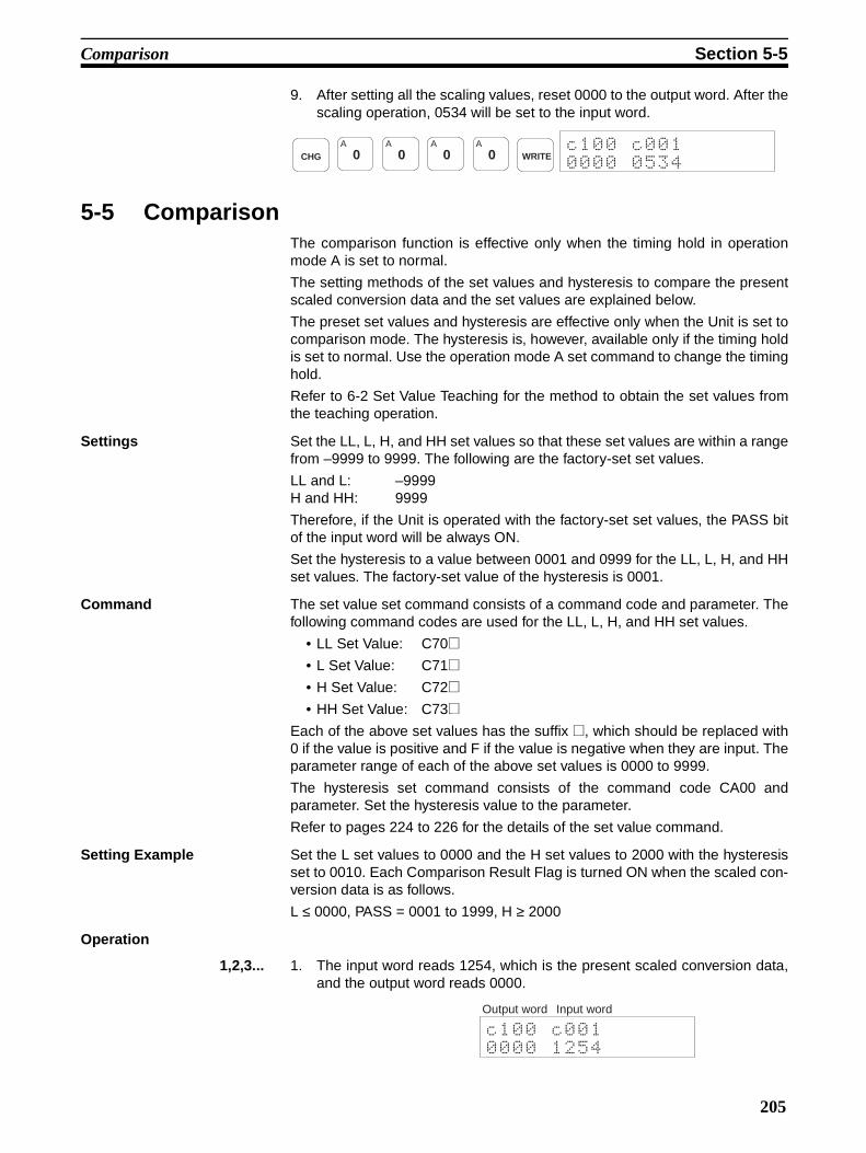
Comparison Section 5-5
9. After setting all the scaling values, reset 0000 to the output word. After thescaling operation, 0534 will be set to the input word.
5-5 ComparisonThe comparison function is effective only when the timing hold in operationmode A is set to normal.
The setting methods of the set values and hysteresis to compare the presentscaled conversion data and the set values are explained below.
The preset set values and hysteresis are effective only when the Unit is set tocomparison mode. The hysteresis is, however, available only if the timing holdis set to normal. Use the operation mode A set command to change the timinghold.
Refer to 6-2 Set Value Teaching for the method to obtain the set values fromthe teaching operation.
Settings Set the LL, L, H, and HH set values so that these set values are within a rangefrom –9999 to 9999. The following are the factory-set set values.
LL and L: –9999H and HH: 9999
Therefore, if the Unit is operated with the factory-set set values, the PASS bitof the input word will be always ON.
Set the hysteresis to a value between 0001 and 0999 for the LL, L, H, and HHset values. The factory-set value of the hysteresis is 0001.
Command The set value set command consists of a command code and parameter. Thefollowing command codes are used for the LL, L, H, and HH set values.
• LL Set Value: C70@• L Set Value: C71@• H Set Value: C72@• HH Set Value: C73@
Each of the above set values has the suffix @, which should be replaced with0 if the value is positive and F if the value is negative when they are input. Theparameter range of each of the above set values is 0000 to 9999.
The hysteresis set command consists of the command code CA00 andparameter. Set the hysteresis value to the parameter.
Refer to pages 224 to 226 for the details of the set value command.
Setting Example Set the L set values to 0000 and the H set values to 2000 with the hysteresisset to 0010. Each Comparison Result Flag is turned ON when the scaled con-version data is as follows.
L ≤ 0000, PASS = 0001 to 1999, H ≥ 2000
Operation
1,2,3... 1. The input word reads 1254, which is the present scaled conversion data,and the output word reads 0000.
CHGA
0A
0A
0A
0 WRITE
Output word Input word
205
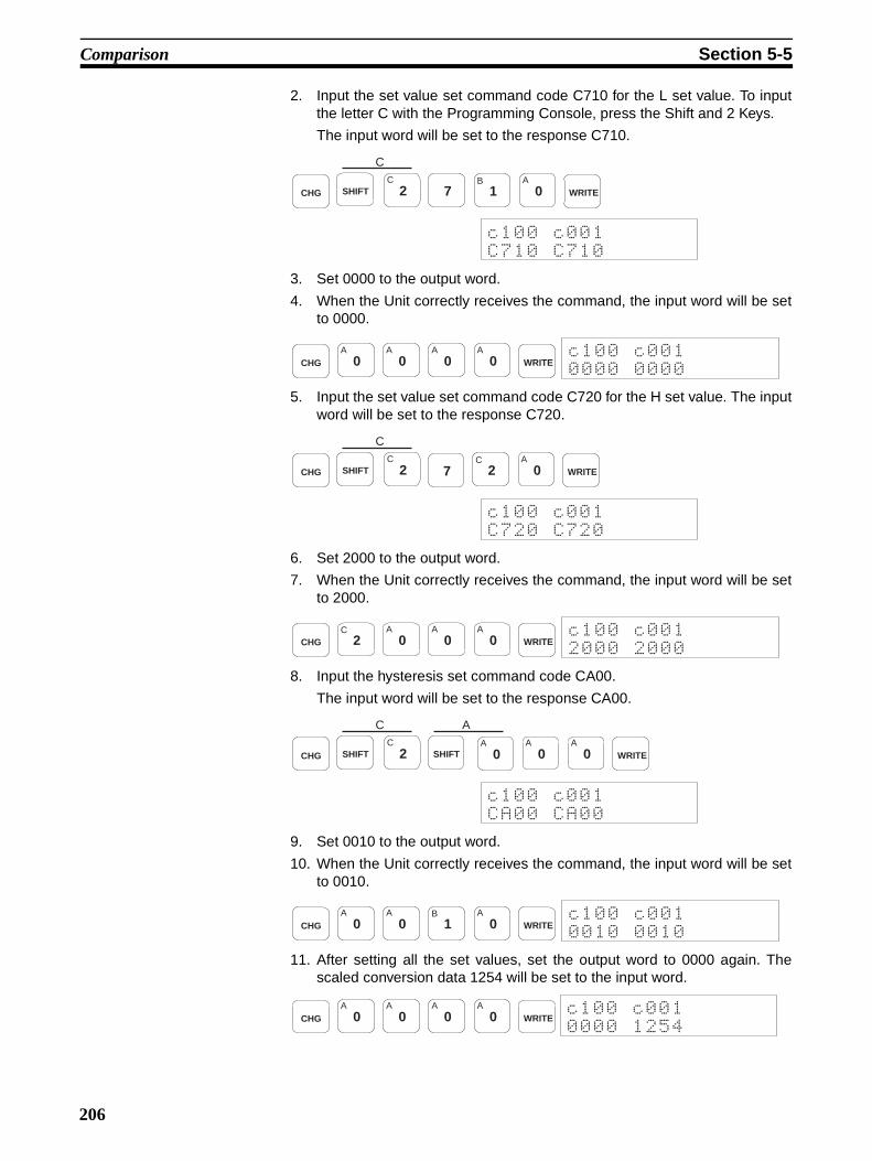
Comparison Section 5-5
2. Input the set value set command code C710 for the L set value. To inputthe letter C with the Programming Console, press the Shift and 2 Keys.
The input word will be set to the response C710.
3. Set 0000 to the output word.
4. When the Unit correctly receives the command, the input word will be setto 0000.
5. Input the set value set command code C720 for the H set value. The inputword will be set to the response C720.
6. Set 2000 to the output word.
7. When the Unit correctly receives the command, the input word will be setto 2000.
8. Input the hysteresis set command code CA00.
The input word will be set to the response CA00.
9. Set 0010 to the output word.
10. When the Unit correctly receives the command, the input word will be setto 0010.
11. After setting all the set values, set the output word to 0000 again. Thescaled conversion data 1254 will be set to the input word.
CHG SHIFT
CC
2 7B
1A
0 WRITE
CHGA
0A
0A
0A
0 WRITE
CHG SHIFT
CC
2 7C
2A
0 WRITE
CHGC
2A
0A
0A
0 WRITE
CHG SHIFT
CC
2 SHIFT
AA
0A
0A
0 WRITE
CHGA
0A
0B
1A
0 WRITE
CHGA
0A
0A
0A
0 WRITE
206
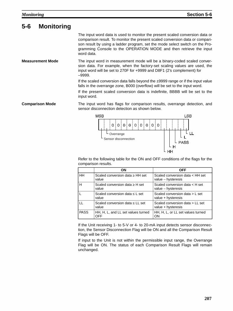
Monitoring Section 5-6
5-6 MonitoringThe input word data is used to monitor the present scaled conversion data orcomparison result. To monitor the present scaled conversion data or compari-son result by using a ladder program, set the mode select switch on the Pro-gramming Console to the OPERATION MODE and then retrieve the inputword data.
Measurement Mode The input word in measurement mode will be a binary-coded scaled conver-sion data. For example, when the factory-set scaling values are used, theinput word will be set to 270F for +9999 and D8F1 (2’s complement) for –9999.
If the scaled conversion data falls beyond the ±9999 range or if the input valuefalls in the overrange zone, B000 (overflow) will be set to the input word.
If the present scaled conversion data is indefinite, BBBB will be set to theinput word.
Comparison Mode The input word has flags for comparison results, overrange detection, andsensor disconnection detection as shown below.
Refer to the following table for the ON and OFF conditions of the flags for thecomparison results.
If the Unit receiving 1- to 5-V or 4- to 20-mA input detects sensor disconnec-tion, the Sensor Disconnection Flag will be ON and all the Comparison ResultFlags will be OFF.
If input to the Unit is not within the permissible input range, the OverrangeFlag will be ON. The status of each Comparison Result Flags will remainunchanged.
ON OFF
HH Scaled conversion data ≥ HH set value
Scaled conversion data < HH set value – hysteresis
H Scaled conversion data ≥ H set value
Scaled conversion data < H set value – hysteresis
L Scaled conversion data ≤ L set value
Scaled conversion data > L set value + hysteresis
LL Scaled conversion data ≤ LL set value
Scaled conversion data > LL set value + hysteresis
PASS HH, H, L, and LL set values turned OFF
HH, H, L, or LL set values turned ON
Sensor disconnection
Overrange
207


SECTION 6Applied Operation
This section describes the applied operation of the Linear Sensor Interface Unit using the Programming Console.
6-1 Scaling Value Teaching . . . . . . . . . . . . . . . . . . . . . . . . . . . . . . . . . . . . . . . . . . 210
6-2 Set Value Teaching . . . . . . . . . . . . . . . . . . . . . . . . . . . . . . . . . . . . . . . . . . . . . 211
6-3 Forced-zero Shift. . . . . . . . . . . . . . . . . . . . . . . . . . . . . . . . . . . . . . . . . . . . . . . 212
6-4 BCD Value Read . . . . . . . . . . . . . . . . . . . . . . . . . . . . . . . . . . . . . . . . . . . . . . . 213
6-5 Monitor Output . . . . . . . . . . . . . . . . . . . . . . . . . . . . . . . . . . . . . . . . . . . . . . . . 214
209

Scaling Value Teaching Section 6-1
6-1 Scaling Value TeachingThe scaling value teach command can be used only when the timing hold inoperation mode A is set to normal.
It is possible to adjust the input scaling values by executing scaling valueteaching with the scaling value teach command. The scaling value teach com-mand uses the following command codes.
• X1 Scaling Value: C500
• X2 Scaling Value: C510
Setting Example In this example, each scaling value is set as shown below. The timing hold isset to normal, and a 4-to 20-mA input sensor is connected to the Unit to mea-sure objects.
X1: 0400X2: 2000Y1: 0000Y2: 1000
Due to a sensor positional error, however, 0002 was obtained for the smallestobject of all the objects and 0996 (with 03E4 displayed on the Unit) wasobtained for the largest object of all the objects.
Therefore, using the teaching function, the X1 value needs adjustment for thesmallest object and the X2 value needs adjustment for the largest object.
Operation For the Smallest Object
1,2,3... 1. Adjust the X1 value with the smallest object using the teaching function.The input word reads 0002, which is the scaled conversion data of thesmallest object measured with the Unit, and the output word reads 0000.
2. Set the scaling value teach command code C500 for the X1 value to theoutput word. To input the letter C with the Programming Console, press theShift and 2 Keys. The input word will be set to the response C500.
3. Set 0000 to the output word. When the input word is set to 0000, which isthe scaled conversion data of the smallest object, the teaching for the X1value has been correctly executed.
Output word Input word
CHG SHIFTC
2
C
SHIFTC
2
C
F5
A0
A0 WRITE
CHGA
0A
0A
0A
0 WRITE
210

Set Value Teaching Section 6-2
For the Largest Object
4. Adjust the X2 value with the largest object next. The input word reads 03E4converted from 996, which is the scaled conversion data of the largest ob-ject measured with the Unit, and the output word reads 0000.
5. Set the scaling value teach command code C510 for the X2 value. The in-put word will be set to the response C510.
6. Set 0000 to the output word. When 03E8 is set to the input word, convertedfrom 1000 (i.e., the scaled conversion data of the largest object measuredwith the Unit), the teaching for the X2 value has been correctly executed.
To check the adjusted values, execute the scaling value read command withthe command code C600 or C610. The X1 value will read 0403 and the X2value will read 1993.
6-2 Set Value TeachingThe set value teach command can be used for the Unit only when the timinghold in operation mode A is set to normal.
It is possible to use appropriate sample objects and adjust the set scaling val-ues by executing set value teaching with the set value teach command as fol-lows.
• LL Set Value: C800
• L Set Value: C810
• H Set Value: C820
• HH Set Value: C830
Setting Example In this example, the timing hold is set to normal, and the L or H set value isadjusted using the teach function. The L set value is used for the smallestobject of all the objects measured by the Unit and the H set value is used forthe largest object of all the objects. The Unit is set to measurement mode sothat the Unit will display the results of the operation.
Operation For the Smallest Object
1,2,3... 1. Adjust the L value with the smallest object using the set value teachingfunction. The input word reads 0100, which is the scaled conversion dataof the smallest object measured with the Unit, and the output word reads0000.
996
CHG SHIFTC
2
C
F5
B1
A0 WRITE
CHGA
0A
0A
0A
0 WRITE
1000
Output word Input word
211

Forced-zero Shift Section 6-3
2. Input the set value teach command code C810 for the L value. To input theletter C with the Programming Console, press the Shift and 2 Keys. The in-put word will be set to the response C810.
3. Set 0000 to the output word. 0100 will be set to the input word.
For the Largest Object
4. Adjust the H value with the largest object next. The input word reads 1000,which is the scaled conversion data of the largest object measured with theUnit, and the output word reads 0000.
5. Input the set value teach command code C820 for the H value. The inputword will be set to the response C820.
6. Set 0000 to the output word again. The input word will be set to 1000.
To check the adjusted values, execute the set value read command with thecommand code C910 or C920.
6-3 Forced-zero ShiftUse the forced-zero shift function to measure the relative values of objectsbased on the standard value determined for the Unit. This function requiresZERO and ZRES (zero reset) inputs to the Unit.
When zero input is turned ON while the Unit is sampling data, the scaled con-version data will be shifted to zero and stored as binary data in the input word,
CHG SHIFTC
2
C
8B
1A
0 WRITE
CHGA
0A
0A
0A
0 WRITE
CHG SHIFTC
2
C
8C
2A
0 WRITE
CHGA
0A
0A
0A
0 WRITE
Side A
Sensor input
Measured value
Object
Zero input ON
Side B
212
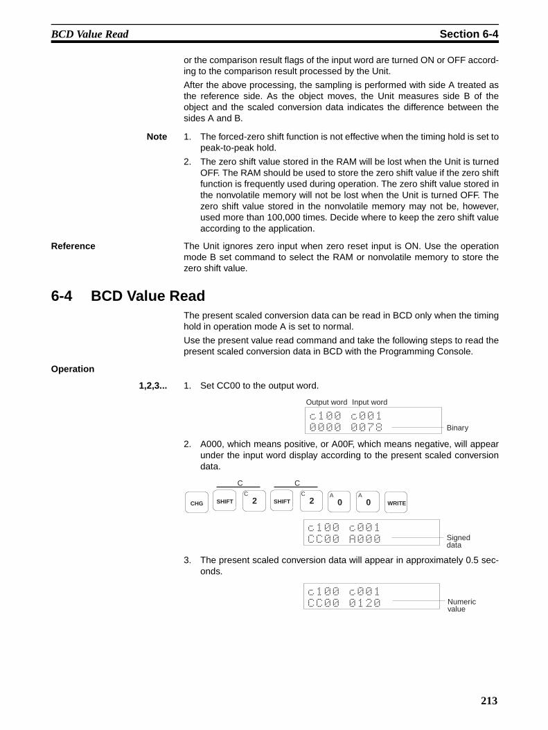
BCD Value Read Section 6-4
or the comparison result flags of the input word are turned ON or OFF accord-ing to the comparison result processed by the Unit.
After the above processing, the sampling is performed with side A treated asthe reference side. As the object moves, the Unit measures side B of theobject and the scaled conversion data indicates the difference between thesides A and B.
Note 1. The forced-zero shift function is not effective when the timing hold is set topeak-to-peak hold.
2. The zero shift value stored in the RAM will be lost when the Unit is turnedOFF. The RAM should be used to store the zero shift value if the zero shiftfunction is frequently used during operation. The zero shift value stored inthe nonvolatile memory will not be lost when the Unit is turned OFF. Thezero shift value stored in the nonvolatile memory may not be, however,used more than 100,000 times. Decide where to keep the zero shift valueaccording to the application.
Reference The Unit ignores zero input when zero reset input is ON. Use the operationmode B set command to select the RAM or nonvolatile memory to store thezero shift value.
6-4 BCD Value ReadThe present scaled conversion data can be read in BCD only when the timinghold in operation mode A is set to normal.
Use the present value read command and take the following steps to read thepresent scaled conversion data in BCD with the Programming Console.
Operation
1,2,3... 1. Set CC00 to the output word.
2. A000, which means positive, or A00F, which means negative, will appearunder the input word display according to the present scaled conversiondata.
3. The present scaled conversion data will appear in approximately 0.5 sec-onds.
Output word Input word
Binary
CHG SHIFTC
2
C
SHIFTC
2
C
A0
A0 WRITE
Signed data
Numeric value
213

Monitor Output Section 6-5
4. A000 or A00F will appear according to the present scaled conversion datain approximately 0.5 seconds.
5. While CC00 is set to the output word, the A000 or A00F and the presentscaled conversion data will be repeatedly displayed alternately at approxi-mately 0.5-s intervals.
6. Set 0000 to the output word again to cancel reading the present scaledconversion data in binary.
6-5 Monitor OutputThe CQM1-LSE02 has a monitor output function.
The CQM1-LSE02 can be in scaled conversion data monitor mode or set dataD/A output mode, either of which can be selected with the operation mode Aset command.
The CQM1-LSE02 in scaled conversion data monitor mode does not requirespecial operation settings. Refer to the following to operate the CQM1-LSE02in set data D/A output mode.
In this mode, the monitor output terminal of the CQM1-LSE02 will have volt-age output corresponding to the scaled conversion data which is written in theoutput word allocated to the Unit. Therefore, the ladder program enables theCQM1-LSE02 to output an analog input signal as a desired voltage value.
Refer to the following table to set signed binary data to use the monitor outputfunction.
There is no setting range restriction except for the following cases.
If the signed binary data of the CQM1-LSE02 output word is the same as orless than D8F0 (–10000), –9.999 V will be output from the monitor output ter-minal. If the signed binary data of the CQM1-LSE02 output word is the sameas or larger than 2710 (10000), 9.999 V will be output from the monitor outputterminal.
Note When obtaining the value to be set to the output word through calculationusing the ladder program, be careful not to use the computed result of “C000to CFFF.” Even when the Unit is used in the set data D/A output mode, if“C000 to CFFF” is set to the output word, it is treated as a command.
In this mode, analog input is converted into digital data and then convertedinto analog output. Therefore, the obtained analog output is not highly precise.
Signed data
CHGA
0A
0A
0A
0 WRITE
Set output binary data Output voltage (V)
2710 (10000) min. 9.999
270F (9999) 9.999
0000 0000
D8F1 (–9999) –9.999
D8F0 (–10000) max. –9.999
214

SECTION 7Commands
This section provides details on the commands and responses of the Linear Sensor Interface Unit.
7-1 Command Usage . . . . . . . . . . . . . . . . . . . . . . . . . . . . . . . . . . . . . . . . . . . . . . . 216
7-2 List of Commands . . . . . . . . . . . . . . . . . . . . . . . . . . . . . . . . . . . . . . . . . . . . . . 218
7-3 Commands and Responses . . . . . . . . . . . . . . . . . . . . . . . . . . . . . . . . . . . . . . . 218
7-3-1 Operation Mode A Set . . . . . . . . . . . . . . . . . . . . . . . . . . . . . . . . . . . 218
7-3-2 Operation Mode A Read. . . . . . . . . . . . . . . . . . . . . . . . . . . . . . . . . . 219
7-3-3 Operation Mode B Set . . . . . . . . . . . . . . . . . . . . . . . . . . . . . . . . . . . 220
7-3-4 Operation Mode B Read . . . . . . . . . . . . . . . . . . . . . . . . . . . . . . . . . . 221
7-3-5 Scaling Value Set . . . . . . . . . . . . . . . . . . . . . . . . . . . . . . . . . . . . . . . 222
7-3-6 Scaling Value Teach . . . . . . . . . . . . . . . . . . . . . . . . . . . . . . . . . . . . . 223
7-3-7 Scaling Value Read . . . . . . . . . . . . . . . . . . . . . . . . . . . . . . . . . . . . . . 223
7-3-8 Set Value Set . . . . . . . . . . . . . . . . . . . . . . . . . . . . . . . . . . . . . . . . . . . 224
7-3-9 Set Value Teach. . . . . . . . . . . . . . . . . . . . . . . . . . . . . . . . . . . . . . . . . 225
7-3-10 Set Value Read . . . . . . . . . . . . . . . . . . . . . . . . . . . . . . . . . . . . . . . . . 225
7-3-11 Hysteresis Set . . . . . . . . . . . . . . . . . . . . . . . . . . . . . . . . . . . . . . . . . . 226
7-3-12 Hysteresis Read . . . . . . . . . . . . . . . . . . . . . . . . . . . . . . . . . . . . . . . . 226
7-3-13 Present Value Read . . . . . . . . . . . . . . . . . . . . . . . . . . . . . . . . . . . . . . 227
215

Command Usage Section 7-1
7-1 Command UsageThere are four types of commands.
The command codes can be set to output word. If no command is used, set0000 to the output word.
When a command is executed, the input word will have a response. If no com-mand is executed, the present scaled conversion data or comparison resultwill be stored in the input word.
Note Some commands cannot be used depending on the contents of settings in theoperation mode A or B.
Teach Commands Scaling Value Teach
Set Value Teach
1,2,3... 1. Set the command code to the output word. The Unit will check the com-mand code. If the command code is correct, the same command code willbe set to the input word as the response for the command. If the commandcode is incorrect, an error code will be set to the input word.
2. After confirming that the response sent back to the input word is correct,set 0000 to the output word.
3. The scaled conversion data or comparison result will stored in the inputword.
Read Commands Operation Mode A Read
Operation Mode B Read
Hysteresis Read
1,2,3... 1. Set the command code to the output word. The Unit will check the com-mand code. If the command code is correct, a set value will be set to theinput word corresponding to the command as the response for the com-mand. If the command code is incorrect, an error code will be set to theinput word.
2. After confirming that the response sent back to the input word is correct,set 0000 to the output word.
Output word
Input word
Command
Command code
Response
Command code
(1) (2) (3)
Set value
Output word
Input word
Command
Command code
Response
(1) (2) (3)
216

Command Usage Section 7-1
3. The scaled conversion data or comparison result will stored in the inputword.
Set Commands Operation Mode A Set
Operation Mode B Set
Scaling Value Set
Set Value Set
Hysteresis Set
1,2,3... 1. Set the command code to the output word. The Unit will check the com-mand code. If the command code is correct, the same command code willbe set to the input word as the response for the command. If the commandcode is incorrect, an error code will be set to the input word.
2. After confirming that the response sent back to the input word is correct,set a parameter to the output word.
3. The Unit will check the parameter. If the parameter is correct, the parame-ter will be set to the input word as the response for the parameter. If theparameter is incorrect, an error code will be set to the input word.
4. After confirming that the response sent back to the input word is correct,set 0000 to the output word. The scaled conversion data or comparison re-sult will stored in the input word.
Signed Set Value Read Commands
Scaling Value Read
Set Value Read
Hysteresis Read
1,2,3... 1. Set the command code to the output word. The Unit will check the com-mand code. If the command code is correct, the sign for a set value will beset to the input word corresponding to the command as the response forthe command. If the command code is incorrect, an error code will be setto the input word.The set value will be set to the input word approximately 0.5 s after the signis set to the input word. The sign and set value will be set to the input wordalternately at approximately 0.5-s intervals.
Output word
Input word
Command
Command code
(1) (2) (3)
Parameter
Response
Command code Parameter
(4)(5)
Sign of set value
(1)(2)
(3)
Set valueSign of set value Set value
Output word
Input word
Command
Command code
Response
(2)
217

List of Commands Section 7-2
2. After confirming that the sign and the set value that the input word is set tois correct, set 0000 to the output word.
3. The scaled conversion data or comparison result will stored in the inputword.
Note The Linear Sensor Interface Unit acknowledges the start or end of a com-mand through a change in the output word value. When “0000” is set to theparameter by the setting command, for example, even if “0000” is set at theend of the command, the command doesn’t end because there is no changein the output word value, not allowing scaled conversion data or comparisonresult to be set in the input word. To end the command, set a value other thanthe one set to the parameter. However, that the value will be reflected on themonitor output if the Unit is used in the set data D/A output mode. Therefore,when using the Unit in the set data D/A output mode, be sure to select a valuewhich will not affect peripheral devices.
7-2 List of CommandsThe following commands can be used to set the initial parameters through theProgramming Console.
7-3 Commands and Responses
7-3-1 Operation Mode A SetThis command is used to set the following operation mode data.
• Data input
• Timing hold
• Input type
• Monitor output
The above items will be stored in the nonvolatile memory and will not be lostafter the Unit is turned OFF.
Command Command code
Meaning Reference page
Operation mode A set C000 Used to set operation mode A. 218
Operation mode A read C100 Used to read the settings of operation mode A. 219
Operation mode B set C200 Used to set operation mode B. 220
Operation mode B read C300 Used to read the settings of operation mode B. 221
Scaling value set C4** Used to set a scaling value. 222
Scaling value teach C5*0 Used to execute scaling value teaching. 223
Scaling value read C6*0 Used to read a scaling value. 223
Set value set C7** Used to set a set value. 224
Set value teach C8*0 Used to execute the set value teaching. 225
Set value read C9*0 Used to read a set value. 225
Hysteresis set CA00 Used to set hysteresis. 226
Hysteresis read CB00 Used to read the hysteresis. 226
Present value read CC00 Used to read the present scaled conversion data. 227
218

Commands and Responses Section 7-3
Command
Command Code
Parameter
Response If the correct command code or parameter is set to the output word, the samecommand code or parameter will be set to the input word.
If the wrong command code or parameter is set to the output word, one of thefollowing error codes will be set to the input word.
E000: This error code will be set to the input word if a nonexisting commandcode is used.
E001: This error code will be set to the input word if the parameter is notwithin the range covered by the Unit.
7-3-2 Operation Mode A ReadThis command is used to read the data that has been input in operation modeA.
Command
Command Code
Parameter Parameters are not used with this command.
Monitor output0: Unchanged1: Scaled conversion data monitor mode (factory-set)2: Set data D/A output monitor mode
Input type0: Unchanged1: ±9.999 V (factory-set)2: ±5 V3: 1 to 5 V4: 4 to 20 mA
Timing hold0: Unchanged1: Normal (factory-set)2: Sampling hold3: Maximum hold4: Minimum hold5: Peak-to-peak hold
Data input0: Unchanged1: Measurement mode (factory-set)2: Comparison mode
219

Commands and Responses Section 7-3
Response If the correct command code is set to the output word, the command code orparameter is set to the input word as a response.
If the wrong command code is set to the output word, the following error codewill be set to the input word.
E000: This error code will be set to the input word if a nonexisting commandcode is used.
7-3-3 Operation Mode B SetThis command is used to set the following.
• Input sampling speed
• Number of mean value processings
• Zero shift value storage area
The above items will be stored in the nonvolatile memory and will not be lostafter the Unit is turned OFF.
Command
Command Code
Monitor output1: Scaled conversion data monitor mode (factory-set)2: Set data D/A output monitor mode
Input type0: Unchanged1: ±9.999 V2: ±5 V3: 1 to 5 V4: 4 to 20 mA
Timing hold0: Unchanged1: Normal2: Sampling hold3: Maximum hold4: Minimum hold5: Peak-to-peak hold
Data input0: Unchanged1: Measurement mode2: Comparison mode
220

Commands and Responses Section 7-3
Parameter
Response If the correct command code or parameter is set to the output word, the com-mand code or parameter is set to the input word as a response.
If the wrong command code or parameter is set to the output word, one of thefollowing error codes will be set to the input word.
E000: This error code will be set to the input word if a nonexisting commandcode is used.
E001: This error code will be set to the input word if the parameter is notwithin the range covered by the Unit.
7-3-4 Operation Mode B ReadThis command is used to read the data that has been input in operation modeB.
Command
Command Code
Parameter Parameters are not used with this command.
Zero shift value storage area0: Unchanged1: RAM (factory-set)2: Nonvolatile memory
Number of mean value processings0: Unchanged1: 12: 23: 4 (factory-set)4: 85: 16
Input sampling speed0: Unchanged1: Fast2: Slow (factory-set)
221

Commands and Responses Section 7-3
Response If the correct command code is set to the output word, the command code orparameter is set to the input word as a response.
If the wrong command code is set to the output word, the following error codewill be set to the input word.
E000: This error code will be set to the input word if a nonexisting commandcode is used.
7-3-5 Scaling Value SetThis command is used to set the X1, X2, Y1, or Y2 scaling value.
If the input type data is changed, the scaling value will be set to the factory-setscaling value.
The set data will be stored in the nonvolatile memory and will not be lost afterthe Unit is turned OFF.
Command
Command Code
Parameter
Response If the wrong command code is set to the output word, the following error codewill be set to the input word.
E000: This error code will be set to the input word if a nonexisting commandcode is used.
Zero shift value storage area1: RAM2: Nonvolatile memory
Number of mean value processings1: 12: 23: 44: 85: 16
Input sampling speed1: Fast2: Slow
Sign0: PositiveF: Negative
Scaling value0: X11: X22: Y13: Y2
ValueRange: 0 to 9999Factory-set values: X1 = 0, X2 = 1000, Y1 = 0, and Y2 = 1000
222

Commands and Responses Section 7-3
E001: This error code will be set to the input word if the parameter is notwithin the range covered by the Unit.
7-3-6 Scaling Value TeachThis command can be used only when the timing hold in operation mode A isset to normal.
This command is used to execute scaling value teaching. When scaling valueteaching is executed, the present input value can be used as the X1 or X2scaling value.
Command
Command Code
Parameter Parameters are not used with this command.
Response If the wrong command code is set to the output word, the following error codewill be set to the input word.
E000: This error code will be set to the input word if a nonexisting commandcode is used.
E002: Teaching command execution error
E003: This error code will be set to the input word if the mode designation forthis command is not correct.
7-3-7 Scaling Value ReadThis command is used to read a scaling value.
Command
Command Code
Parameter Parameters are not used with this command.
Teaching scaling value0: X11: X2
Scaling value0: X11: X22: Y13: Y2
223

Commands and Responses Section 7-3
Response If the output word is set to the correct command code, the sign of the scalingvalue and the scaling value will be set to the input word alternately in the fol-lowing format.
If the wrong command code is set to the output word, the following error codewill be set to the input word.
E000: This error code will be set to the input word if a nonexisting commandcode is used.
7-3-8 Set Value SetThis command is used to set the HH, H, L, or LL set value.
The set value will be stored in the nonvolatile memory and will not be lost afterthe Unit is turned OFF.
Command
Command Code
Parameter
Response If the correct command code or parameter is set to the output word, the samecommand code or parameter will be set to the input word.
If the wrong command code or parameter is set to the output word, one of thefollowing error codes will be set to the input word.
E000: This error code will be set to the input word if a nonexisting commandcode is used.
E001: This error code will be set to the input word if the parameter is notwithin the range covered by the Unit.
Sign
0: PositiveF: Negative
ValueRange: 0 to 9999Factory-set values: X1 = 0, X2 = 1000, Y1 = 0, and Y2 = 1000
Sign0: Positive (Factory-set HH and H set values)F: Negative (Factory-set LL and L set values)
Set value0: LL1: L2: H3: HH
ValueRange: 0 to 9999Factory-set value: 9999
224

Commands and Responses Section 7-3
7-3-9 Set Value TeachThis command can be used only when the timing hold in operation mode A isset to normal.
This command is used to execute set value teaching. When set value teach-ing is executed, the present input value can be used as the HH, H, L or LL setvalue.
CommandCommand Code
Parameter Parameters are not used with this command.
Response If the wrong command code is set to the output word, the following error codewill be set to the input word.
E000: This error code will be set to the input word if a nonexisting commandcode is used.
E002: Teaching command execution error
E003: This error code will be set to the input word if the mode designation forthis command is not correct.
7-3-10 Set Value ReadThis command is used to read a set value.
Command
Command Code
Parameter Parameters are not used with this command.
Response If the output word is set to the correct command code, the sign of the set valueand the set value will be set to the input word alternately in the following for-mat.
Teaching set value0: LL1: L2: H3: HH
Set value0: LL1: L2: H3: HH
Sign
0: PositiveF: Negative
ValueRange: 0 to 9999
225

Commands and Responses Section 7-3
If the output word is set to the wrong command code, the following errorcodes will be set to the input word.
E000: This error code will be set to the input word if a nonexisting commandcode is used.
7-3-11 Hysteresis SetThis command is used to set the hysteresis.
If the input type data is changed, the hysteresis will be reset to its factory-setvalue.
The set data will be stored in the nonvolatile memory and will not be lost afterthe Unit is turned OFF.
Command
Command Code
Parameter
Response If the correct command code or parameter is set to the output word, the samecommand code or parameter will be set to the input word.
If the wrong command code or parameter is set to the output word, one of thefollowing error codes will be set to the input word.
E000: This error code will be set to the input word if a nonexisting commandcode is used.
E001: This error code will be set to the input word if the parameter is notwithin the range covered by the Unit.
7-3-12 Hysteresis ReadThis command is used to read the hysteresis.
Command
Command Code
Parameter Parameters are not used with this command.
Response If the correct command code or parameter is set to the output word, the samecommand code or parameter will be set to the input word.
If the wrong command code or parameter is set to the output word, one of thefollowing error codes will be set to the input word.
E000: This error code will be set to the input word if a nonexisting commandcode is used.
Range: 0001 to 0999Factory-set value: 0001
Range: 0001 to 0999Default value: 0001
226

Commands and Responses Section 7-3
7-3-13 Present Value ReadThis command can be used only when the timing hold in operation mode A isset to normal.
This command is used to read the present measured value after scaling.
Command
Command Code
Parameter Parameters are not used with this command.
Response If the correct command code or parameter is set to the output word, thepresent conversion data will be set to the input word.
If the wrong command code or parameter is set to the output word, one of thefollowing error codes will be set to the input word.
E000: This error code will be set to the input word if a nonexisting commandcode is used.
E003: This error code will be set to the input word if the mode designation forthis command is not correct.
Sign
0: PositiveF: Negative
ValueRange: 0 to 9999
227


Appendix ASpecifications
Standard SpecificationsThe standard specifications of the CQM1-LSE01/LSE02 conform to those of SYSMAC CQM1H/CQM1-seriesPCs.
Performance SpecificationsItem CQM1-LSE01 CQM1-LSE02
Input No. of analog input points 1
Input range Voltage input 1 to 5 V, –9.999 to 9.999 V, –5 to 5 V
Current input 4 to 20 mA
Input impedance
Voltage input 1 MΩ min.
Current input 10 ΩLinearity ±0.1% FS ±1 digit max. with input sampling speed set to slow
±0.5% FS ±1 digit max. with input sampling speed set to fast
PC output code Signed binary (–9999 to 9999)
Sampling time 0.3 ms with input sampling speed set to fast and 0.6 ms with input sampling speed set to slow
Sampling period 1 ms with input sampling speed set to fast and 2 ms with input sampling speed set to slow
Operation processing time 5 ms
External control input TIMING/GATE, ZERO, ZERO RESET, RESET
No. of occupied words 1 input word and 1 output word
Moni-tor out-put
Voltage output --- –9.999 V to 9.999 V
Output linearity --- ±0.1% FS
Output resolution --- 1/8192
Output refresh period --- 0.5 s
Output response time --- 0.5 s
Permissible load resis-tance
--- 10 kΩ min.
Insulation method Photocoupler insulation between input terminals and PC signals and between input terminals and output terminals.
Dielectric strength 500 VAC for 1 minute between input terminals and output terminals1,000 VAC for 1 minute between I/O terminals and FG
Current consumption 380 mA max. at 5 VDC 450 mA max. at 5 VDC
Dimensions 32 x 110 x 107 (W x H x D) mm
Weight 230 g max.
229

Specifications Appendix A
External Control Input Specifications
Note The ON/OFF response time is the time required for the Unit’s CPU to detect input turned ON or OFF.
Dimensions
Item Specification
Input voltage 24 VDC +10%/–15%
Input impedance TIMING/GATE: 2 kΩOther control output: 2.2 kΩ
Input current TIMING/GATE: 9.2 mA TYP.Other control output: 10 mA TYP. (24 VDC)
ON voltage TIMING/GATE: 16.3 VDC min.Other control output: 17.1 VDC min.
OFF voltage TIMING/GATE: 3.8 VDC max.Other control output: 3.6 VDC max.
ON/OFF response time (see note)
TIMING/GATE: 50 µs TYP.Other control output: 4 ms TYP.
Circuit configuration
Internal circuitry
Figures in parentheses are values for TIMING input and GATE input.
24 VDC 820 Ω (1.2 kΩ)
2.2 Ω (2 kΩ)
(Unit: mm)
230

Appendix BBlock Diagram
Voltage/Current input
Control input powersupply (24 VDC)
Control input
Monitor output
Input circuit
Analog-Digi-tal conversion circuit
Control input circuit
Digital-analog output circuit
Indicator circuit
Microcomputer
Bus interface circuit
Nonvola-tile memory
CQM1H/CQM1 internal bus
Input and analog-digital conversion circuits
Digital-Analog output circuit
Voltage stabi-lizing circuit
Voltage stabi-lizing circuit
Power supply circuit
Internal circuit
Internal power supply
231


Appendix CData Processing Timing
SamplingThe Unit processes input data in the following two blocks.
• A: Input sampling time = Sampling period x No. of mean value processings
• B: Operation process and data set to the data input word
The Unit has the following two sampling periods.
• Fast: 1 ms (with 0.3-ms sampling time)
• Slow: 2 ms (with 0.6-ms sampling time)
The necessity of the sampling hold process depends on the timing hold.
Sampling ExampleThe following are typical sampling timing examples.
Example 1 Timing Hold: NormalNo. of Mean Value Processings: 1Input Sampling Speed: Fast
Example 2 Timing Hold: Sampling holdNo. of Mean Value Processings: 4Input Sampling Speed: Fast
Data processing Next data processing
Timing input
0.05 ms min.
Waiting for next timing input
233

Data Processing Timing Appendix C
Example 3 Timing Hold: Maximum holdNo. of Mean Value Processings: 2Input Sampling Speed: Fast
Data ReadWhen a ladder program is used to automatically read the data to be input, the data is sampled in synchroniza-tion with timing input. Therefore, the CPU used with the Unit must read the data in synchronization with thesampling timing.
Timing Input Connected in ParallelThe timing signal can connect with the TIMING/GATE terminal and the input word of the CPU in parallel asshown in the following illustration to synchronize the operation of the CPU and the sampling timing of the Unit.
The Unit requires time to process input and to set data to its input word corresponding to the input. The actualdata reading timing must be later than the moment timing input to the Unit is ON. The input process time varieswith the timing hold currently selected. The following is the input process time with its timing hold set to sam-pling hold.
Maximum hold processing This value is invalid. Waiting for next timing input
Timing input
B'B'
CQM1-LSE01/LSE02
CPU
Timing signal
Input sampling Operation process and data set
Time required until the data is set.
Timing input
234

Data Processing Timing Appendix C
Using Reset InputConnect a bit of the output word to the Unit’s reset input terminal. If reset input is ON, the input word will be setto BBBB (i.e., the factory-set setting of the input word). Take the following steps to set the input word to BBBB.
1,2,3... 1. Turn reset input ON.
2. When BBBB is set to the input word, turn reset input OFF.
3. If BBBB is set to data other than the input word, let the Unit read the data.
4. Repeat the above steps.
Timing Input and Reset InputWhen the timing hold is not set to normal or sampling hold, timing input to the Unit will work as gate input, inwhich case reset input to the Unit will work as follows:
1,2,3... 1. If timing input is turned OFF while reset input is ON, the present scaled conversion data will notbe effective and BBBB will be read as the present scaled conversion data.
2. The Unit will sample and process input from the moment reset input is turned OFF to the momenttiming input is turned OFF, in which case, while the reset input in ON, BBBB will be read as thepresent scaled conversion data.
3. The Unit will sample and process input from the moment reset input is turned OFF to the momenttiming input is OFF, in which case, input from the moment the timing input is turned ON to the mo-ment reset input is turned ON will not be effective.
4. The Unit will ignore timing input while reset input is ON.
Start
Turn reset input ON
Turn reset input OFF
Read input word data
N
Y
Y
N
BBBB set to input word
BBBB set to input word
Timing input
Reset input
(1) (2) (3) (4)
235


Appendix DTroubleshooting
Internal ErrorERR indicator is lit.
Sensor ErrorBROKEN-WIRE indicator is lit.
Overflow
Command Error
Word status Possible cause and remedy
BEEE CPU error.Turn the power OFF and then ON again, once. If the ERR indicator is still lit, the Unit needs repairs.
B010 RAM error (calibration data error).Turn the power OFF and then ON again, once. If the ERR indicator is still lit, the Unit needs repairs.
B011 Set value data error.Turn the power OFF and then ON again, once, or reset all the initial values of the Unit again and execute the zero reset.
Word status Possible cause and remedy
B001 (measurement mode)Bit 15 = 1 (comparison mode)
Check if the wires of the sensor connected to the Unit are broken, short circuited, or incor-rectly connected to the Unit.
Word status Possible cause and remedy
B000 (measurement mode)Bit 14 = 1 (comparison mode)
Set all the set values within the permissible ranges of the Unit.
Word status Possible cause and remedy
E000 A nonexisting command code was used. Check the command description.
E001 Parameter setting range error. Set the parameter correctly and execute the command.
E002 Teach command execution error.Cancel the following conditions and execute the teach command again.
Reset inputSensor errorOverflow
E003 Mode designation error.The command C500, C800, or CC00 can be set to the output word only when the timing hold mode is set to normal. Set the timing hold mode to normal in the operation mode A and execute the required command again.
237


PART VIIITemperature Control Units
CQM1-TC001CQM1-TC002
CQM1-TC101
CQM1-TC102CQM1-TC201
CQM1-TC202
CQM1-TC301CQM1-TC302
CQM1-TC203
CQM1-TC204CQM1-TC303
CQM1-TC304
239


SECTION 1Temperature Control Unit Model Numbers
This section lists the Temperature Control Unit model numbers and the basic specifications for each Unit.
241
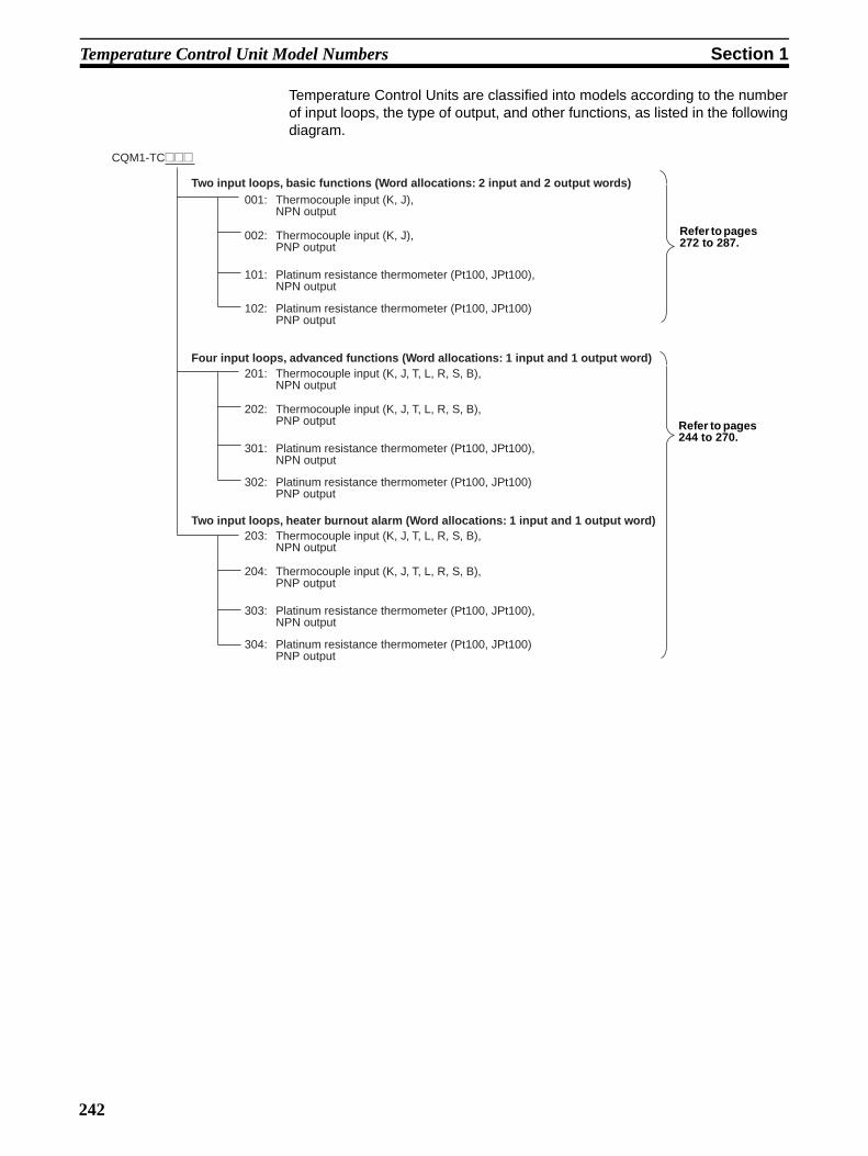
Temperature Control Unit Model Numbers Section 1
Temperature Control Units are classified into models according to the numberof input loops, the type of output, and other functions, as listed in the followingdiagram.
CQM1-TC@@@
001: Thermocouple input (K, J), NPN output
Two input loops, basic functions (Word allocations: 2 input and 2 output words)
Four input loops, advanced functions (Word allocations: 1 input and 1 output word)
Two input loops, heater burnout alarm (Word allocations: 1 input and 1 output word)
002: Thermocouple input (K, J), PNP output
101: Platinum resistance thermometer (Pt100, JPt100), NPN output
102: Platinum resistance thermometer (Pt100, JPt100)PNP output
201: Thermocouple input (K, J, T, L, R, S, B), NPN output
202: Thermocouple input (K, J, T, L, R, S, B), PNP output
301: Platinum resistance thermometer (Pt100, JPt100), NPN output
302: Platinum resistance thermometer (Pt100, JPt100)PNP output
203: Thermocouple input (K, J, T, L, R, S, B), NPN output
204: Thermocouple input (K, J, T, L, R, S, B), PNP output
303: Platinum resistance thermometer (Pt100, JPt100), NPN output
304: Platinum resistance thermometer (Pt100, JPt100)PNP output
Refer to pages 272 to 287.
Refer to pages 244 to 270.
242

SECTION 2CQM1-TC20@/TC30@ Temperature Control Units
This section describes the features and operation of the CQM1-TC20@/TC30@ Temperature Control Units.
2-1 Features and Word Allocations . . . . . . . . . . . . . . . . . . . . . . . . . . . . . . . . . . . . 244
2-1-1 Features. . . . . . . . . . . . . . . . . . . . . . . . . . . . . . . . . . . . . . . . . . . . . . . 244
2-1-2 Word Allocations . . . . . . . . . . . . . . . . . . . . . . . . . . . . . . . . . . . . . . . 244
2-2 Specifications . . . . . . . . . . . . . . . . . . . . . . . . . . . . . . . . . . . . . . . . . . . . . . . . . 245
2-3 Nomenclature . . . . . . . . . . . . . . . . . . . . . . . . . . . . . . . . . . . . . . . . . . . . . . . . . 248
2-4 Terminology and Function Descriptions . . . . . . . . . . . . . . . . . . . . . . . . . . . . . 251
2-5 Wiring . . . . . . . . . . . . . . . . . . . . . . . . . . . . . . . . . . . . . . . . . . . . . . . . . . . . . . . 253
2-6 Application . . . . . . . . . . . . . . . . . . . . . . . . . . . . . . . . . . . . . . . . . . . . . . . . . . . 254
2-6-1 Communications Procedure . . . . . . . . . . . . . . . . . . . . . . . . . . . . . . . 255
2-6-2 Using Operation Control Commands . . . . . . . . . . . . . . . . . . . . . . . . 258
2-7 IOTC(––). . . . . . . . . . . . . . . . . . . . . . . . . . . . . . . . . . . . . . . . . . . . . . . . . . . . . 262
2-7-1 Sending I/O Allocation Commands . . . . . . . . . . . . . . . . . . . . . . . . . 262
2-7-2 Sending Operation Control Commands . . . . . . . . . . . . . . . . . . . . . . 263
2-8 Troubleshooting . . . . . . . . . . . . . . . . . . . . . . . . . . . . . . . . . . . . . . . . . . . . . . . 269
2-9 Command Tables. . . . . . . . . . . . . . . . . . . . . . . . . . . . . . . . . . . . . . . . . . . . . . . 270
243

Features and Word Allocations Section 2-1
2-1 Features and Word Allocations
2-1-1 Features• The PID with advanced feed-forward circuitry (2 degrees of freedom) of
the CQM1-TC20@/TC30@ assures stable temperature control. The Unitscan also be set to ON/OFF control.
• Temperature Control Units are available for either 4-loop temperature con-trol or 2-loop temperature control, and Units with 2-loop temperature con-trol provide a heater burnout alarm. You can also select betweenthermocouples or platinum resistance thermometers as the input sensors.
Temperature Control Units
Temperature Ranges
Note K (CA) = Chromel/alumel, J (IC) = Iron/constantan, T (CC) = Copper/constan-tan, L = Iron/constantan, R = Platinum/platinum rhodium 13%, S = Platinum/platinum rhodium 10%, B = Platinum rhodium 30%/platinum rhodium 6%
2-1-2 Word Allocations• One word each is allocated to the Temperature Control Unit for inputs and
outputs.
• Commands are used to set and read data.
Inputs Output type
NPN outputs PNP outputs
4 loops Thermocouples CQM1-TC201 CQM1-TC202
Platinum resistance thermometers
CQM1-TC301 CQM1-TC302
2 loops with heater burnout alarm
Thermocouples CQM1-TC203 CQM1-TC204
Platinum resistance thermometers
CQM1-TC303 CQM1-TC304
Thermocouples (See note.) Platinum resistance thermometers
K (CA) K (CA) J (IC) J (IC) T (CC) L L R S B Pt100 JPt100 Pt100 JPt100 ---
Code No.
0 1 2 3 4 5 6 7 8 9 0 1 2 3 4 to 9
Min. unit
1°C 0.1°C 1°C 0.1°C 0.1°C 1°C 0.1°C 1°C 0.1°C 0.01°C ---
Term
pera
ture
ran
ge (
degr
ees
C)
1800
1600
1300
800
600
400
300
200
100
0
−100
−200
1300
−200
500.0
0.0
850
−100
400.0
0.0
400.0
0.0
400.0
−200.0
850
−100
1700
0
1700
0
1800
100
650.0
−200.0
650.0
−200.0
250.0
−20.0
250.0
−20.0D
o no
t set
.
244
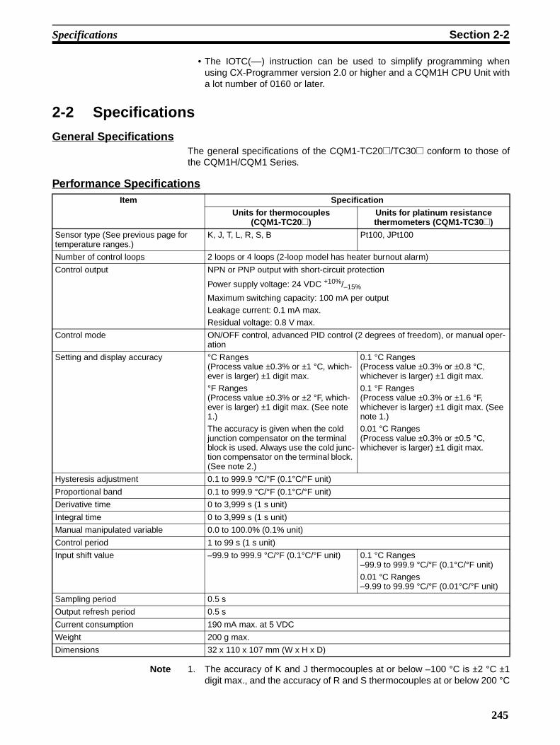
Specifications Section 2-2
• The IOTC(––) instruction can be used to simplify programming whenusing CX-Programmer version 2.0 or higher and a CQM1H CPU Unit witha lot number of 0160 or later.
2-2 Specifications
General SpecificationsThe general specifications of the CQM1-TC20@/TC30@ conform to those ofthe CQM1H/CQM1 Series.
Performance Specifications
Note 1. The accuracy of K and J thermocouples at or below –100 °C is ±2 °C ±1digit max., and the accuracy of R and S thermocouples at or below 200 °C
Item Specification
Units for thermocouples (CQM1-TC20@)
Units for platinum resistance thermometers (CQM1-TC30@)
Sensor type (See previous page for temperature ranges.)
K, J, T, L, R, S, B Pt100, JPt100
Number of control loops 2 loops or 4 loops (2-loop model has heater burnout alarm)
Control output NPN or PNP output with short-circuit protection
Power supply voltage: 24 VDC +10%/–15%
Maximum switching capacity: 100 mA per outputLeakage current: 0.1 mA max.
Residual voltage: 0.8 V max.
Control mode ON/OFF control, advanced PID control (2 degrees of freedom), or manual oper-ation
Setting and display accuracy °C Ranges(Process value ±0.3% or ±1 °C, which-ever is larger) ±1 digit max. °F Ranges (Process value ±0.3% or ±2 °F, which-ever is larger) ±1 digit max. (See note 1.)The accuracy is given when the cold junction compensator on the terminal block is used. Always use the cold junc-tion compensator on the terminal block. (See note 2.)
0.1 °C Ranges (Process value ±0.3% or ±0.8 °C, whichever is larger) ±1 digit max.0.1 °F Ranges (Process value ±0.3% or ±1.6 °F, whichever is larger) ±1 digit max. (See note 1.)0.01 °C Ranges (Process value ±0.3% or ±0.5 °C, whichever is larger) ±1 digit max.
Hysteresis adjustment 0.1 to 999.9 °C/°F (0.1°C/°F unit)
Proportional band 0.1 to 999.9 °C/°F (0.1°C/°F unit)
Derivative time 0 to 3,999 s (1 s unit)
Integral time 0 to 3,999 s (1 s unit)
Manual manipulated variable 0.0 to 100.0% (0.1% unit)
Control period 1 to 99 s (1 s unit)
Input shift value –99.9 to 999.9 °C/°F (0.1°C/°F unit) 0.1 °C Ranges–99.9 to 999.9 °C/°F (0.1°C/°F unit)0.01 °C Ranges–9.99 to 99.99 °C/°F (0.01°C/°F unit)
Sampling period 0.5 s
Output refresh period 0.5 s
Current consumption 190 mA max. at 5 VDC
Weight 200 g max.
Dimensions 32 x 110 x 107 mm (W x H x D)
245
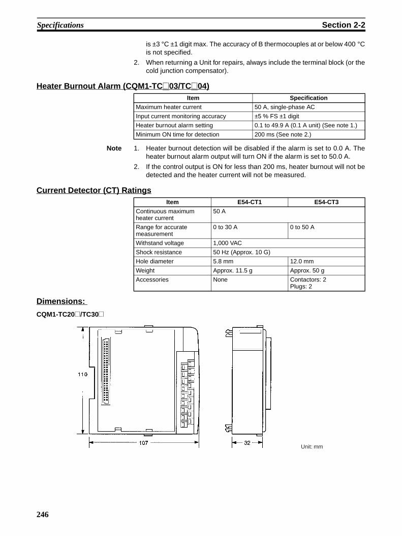
Specifications Section 2-2
is ±3 °C ±1 digit max. The accuracy of B thermocouples at or below 400 °Cis not specified.
2. When returning a Unit for repairs, always include the terminal block (or thecold junction compensator).
Heater Burnout Alarm (CQM1-TC@03/TC@04)
Note 1. Heater burnout detection will be disabled if the alarm is set to 0.0 A. Theheater burnout alarm output will turn ON if the alarm is set to 50.0 A.
2. If the control output is ON for less than 200 ms, heater burnout will not bedetected and the heater current will not be measured.
Current Detector (CT) Ratings
Dimensions:
CQM1-TC20@/TC30@
Item Specification
Maximum heater current 50 A, single-phase AC
Input current monitoring accuracy ±5 % FS ±1 digit
Heater burnout alarm setting 0.1 to 49.9 A (0.1 A unit) (See note 1.)
Minimum ON time for detection 200 ms (See note 2.)
Item E54-CT1 E54-CT3
Continuous maximum heater current
50 A
Range for accurate measurement
0 to 30 A 0 to 50 A
Withstand voltage 1,000 VAC
Shock resistance 50 Hz (Approx. 10 G)
Hole diameter 5.8 mm 12.0 mm
Weight Approx. 11.5 g Approx. 50 g
Accessories None Contactors: 2Plugs: 2
Unit: mm
246

Specifications Section 2-2
Current Detector (Sold Separately)
E54-CT1
E54-CT3
5.8 dia.
Two, 3.5 dia. holes
2.36 dia.
12 dia.
Two, M3 (depth: 4)
Unit: mm
40
9
30
21
15 2.8
30
40
30
40
10.5 3
10
25
7.5
247

Nomenclature Section 2-3
2-3 Nomenclature
Front View
Side View
Ready indicator (green, lit when the Unit is recognized as the Temperature Control Unit)
Four-loop ModelsOUT1 to OUT4 indicators (orange, lit when control output is ON)
Two-loop ModelsOUT1 and OUT2 indicators (orange, lit when control output is ON)HB1 and HB2 indicators (red, lit when a heater burnout has been detected)
Terminal screws: M3
Function DIP switch (SW1)
CoverLoops 1 and 3
Slide lock
Terminals
Slide lock
Input type DIP switch (SW2)
ON
OFF
ON
OFF
Loops 2 and 4
248

Nomenclature Section 2-3
Switch Settings Set all switches before mounting the Unit. Factory settings are shown in boldtext in the following table.
Note 1. Do not use this setting for platinum resistance thermometers; 0.01°F rang-es are not supported.
2. The following ranges must be used when 4-digit BCD is specified:
0.1°C/°F ranges: –99.9 (F999) to 999.9 (9999)0.01°C/°F ranges: –9.99 (F999) to 99.99 (9999)
Note 1. : ON, : OFF
2. All pins are turned OFF at the factory.
3. Do not use any settings that are not specified above.
Pin Item Settings
1 Control method ON Advanced PID
OFF ON/OFF
2 Control operation for loops 1 and 3
ON Normal (cooling control)
OFF Reverse (heating control)
3 Control operation for loops 2 and 4
ON Normal (cooling control)
OFF Reverse (heating control)
4 Temperature unit ON °F (See note 1.)
OFF °C5 Data type ON 4-digit BCD
OFF 16-bit binary (4-digit Hex)
6 Leave this switch set to OFF.
Function DIP Switch (SW1)ON
OFF
Code No.
Input type Setting
Units for thermocouples (CQM1-TC20@)
Units for platinum resistance thermometers (CQM1-TC30@)
Loops 1 and 3 Loops 2 and 4
1 2 3 4 5 6 7 8
0 K, –200 to 1,300 °C Pt100, –200.0 to 650.0 °C
1 K, 0.0 to 500.0 °C JPt100, –200.0 to 650.0 °C
2 J, –100 to 850 °C Pt100, –20.00 to 250.00 °C
3 J, 0.0 to 400.0 °C JPt100, –20.00 to 250.00 °C
4 T, –200.0 to 400.0 °C Do not set.
5 L, –100 to 850 °C Do not set.
6 L, 0.0 to 400.0 °C Do not set.
7 R, 0 to 1,700 °C Do not set.
8 S, 0 to 1,700 °C Do not set.
9 B, 100 to 1,800 °C Do not set.
Input Type DIP Switch (SW2)
Pins 5 to 8: Thermocouple type and range setting for loops 2 and 4
Pins 1 to 4: Thermocouple type and range setting for loops 1 and 3
ON
OFF
249

Nomenclature Section 2-3
Temperature Ranges
Units for Thermocouples The setting ranges are shown in the following table. Indication ranges are thesetting range ±20°C/°F. (See note 1.)
Units for Platinum Resistance Thermometers
The setting ranges are shown in the following table. Indication ranges are thesetting range ±20 °C/°F. (See note 1.)
Note 1. For binary indications, a sensor error (E400) will occur if the specifiedrange is exceeded. In Auto Mode, the output for the corresponding loop willturn OFF if this error occurs.
2. For BCD indications, the indicated values will be clamped to the upper orlower limit between the upper or lower limit of the setting range and the val-ues that will cause a sensor error (E400),0.1 °C/°F Indications: Lower limit = –99.9, Upper limit = 999.90.01 °C Indications: Lower limit = –9.99, Upper limit = 99.99
3. The lower limit of indications for B thermocouples is 0 °C/°F.
Code No.
Input type
°C °FBinary
(4-digit Hex)BCD Binary
(4-digit Hex)BCD
0 K FF38 to FFFF to 0514(–200 to –1 to 1300)
F200 to 1300(–200 to 1300)
FED4 to FFFF to 08FC(–300 to –1 to 2300)
F300 to 2300(–300 to 2300)
1 K 0000 to 1388(0.0 to 500.0)
0000 to 5000(0.0 to 500.0)
0000 to 2328(0.0 to 900.0)
0000 to 9000(0.0 to 900.0)
2 J FF9C to FFFF to 0352(–100 to –1 to 850)
F100 to 0850(–100 to 850)
FF9C to FFFF to 05DC(–100 to –1 to 1500)
F100 to 1500(–100 to 1500)
3 J 0000 to 0FA0(0.0 to 400.0)
0000 to 4000(0.0 to 400.0)
0000 to 1D4C(0.0 to 750.0)
0000 to 7500(0.0 to 750.0)
4 T F830 to FFFF to 0FA0(–200.0 to –0.1 to 400.0)
F999 to 4000 (See note 2.)(–99.9 to 400.0)
F448 to FFFF to 1B53(–300.0 to –0.1 to 700.0)
F999 to 7000 (See note 2.)(–99.9 to 700.0)
5 L FF9C to FFFF to 0352(–100 to –1 to 850)
F100 to 0850 (–100 to 850)
FF9C to FFFF to 05DC(–100 to –1 to 1500)
F100 to 1500(–100 to 1500)
6 L 0000 to 0FA0(0.0 to 400.0)
0000 to 4000 (0.0 to 400.0)
0000 to 1D4C (0.0 to 750.0)
0000 to 7500(0.0 to 750.0)
7 R 0000 to 06A4(0 to 1700)
0000 to 1700(0 to 1700)
0000 to 0BB8 (0 to 3000)
0000 to 3000 (0 to 3000)
8 S 0000 to 06A4 (0 to 1700)
0000 to 1700 (0 to 1700)
0000 to 0BB8 (0 to 3000)
0000 to 3000 (0 to 3000)
9 B (See note 3.)
0064 to 0708 (100 to 1800)
0100 to 1800 (100 to 1800)
012C to 0C80 (300 to 3200)
0300 to 3200 (300 to 3200)
Code No.
Input type
°C °FBinary
(4-digit Hex)BCD Binary
(4-digit Hex)BCD
0 Pt100 F830 to FFFF to 1964 (–200.0 to –0.1 to 650.0)
F999 to 6500 (See note 2.)(–99.9 to 650.0)
F448 to FFFF to 2EE0(–300.0 to –1 to 1200.0)
F999 to 9999 (See note 2.)(–99.9 to 999.9)
1 JPt100 F830 to FFFF to 1964 (–200.0 to –0.1 to 650.0)
F999 to 6500 (See note 2.) (–99.9 to 650.0)
F448 to FFFF to 2EE0(–300.0 to –1 to 1200.0)
F999 to 9999 (See note 2.)(–99.9 to 999.9)
2 Pt100 F830 to FFFF to 61A8(–20.00 to –0.01 to 250.00)
F999 to 9999 (See note 2.) (–9.99 to 99.99)
Do not set. (See note 4.)
3 JPt100 F830 to FFFF to 61A8(–20.00 to –0.01 to 250.00)
F999 to 9999 (See note 2.) (–9.99 to 99.99)
4 to 9 --- Do not set. (See note 4.)
250

Terminology and Function Descriptions Section 2-4
4. Do not use any settings other than those specified above.
5. The set points and input shift values will change as follows if the input typeis changed:
• The set points will be clamped at the upper or lower limit if the settingrange is exceeded.
• The decimal points will be adjusted if the range is changed to anotherrange with a different number of decimal places.Example: If pin 1 on SW2 is turned ON, the K thermocouple range willbe changed from –200 to 1,300 °C to 0.0 to 500.0 °C. If a set point waspreviously 200 °C, it will be changed to 20.0 °C.
2-4 Terminology and Function Descriptions
Manual Manipulated VariableThe manual manipulated variable can be used only as a time-proportionalratio. Control is continued based on the final output level when automatic con-trol (ON/OFF or advanced PID) is switched to manual operation. This functionenables the output to be controlled artificially without using RUN or STOPcommands or altering the input status (e.g., for sensor errors). An example ofapplication is shown below.
Heater Burnout Alarm • The heater burnout alarm output is a latched output. To reset the heaterburnout alarm output, either set the heater burnout alarm set value to 0.0or turn the power supply to the Unit OFF and then back ON.
• The heater burnout alarm settings are shown in the following table.
• Heater CurrentIf the heater current reaches 55.0 A or higher, a CT input error will occurand E500 will be output if the heater current is being monitored.
• The current at which a heater burnout will be detected is calculated as fol-lows:
Set value = (Normal current + current after burnout)/2
• The following condition must be met:
Normal current – current after burnout ≥ 2.5 A
Manual manipulated variable changed
Output
Manual Auto
Changed
Auto
Changed
0%
Setting Operation
0.0 Heater burnouts will not be detected. The heater burn-out alarm output will turn OFF. This setting is used to reset an alarm.
0.1 to 49.9 The detection level for heater burnout alarms.
50.0 Heater burnouts will not be detected. The heater burn-out alarm output will turn ON regardless of RUN/STOP status. This setting can be used to check wiring.
251

Terminology and Function Descriptions Section 2-4
Measurements will not be stable if the difference is less than 2.5 A. Ifthe difference is less than 2.5 A, wrap the wire around the CT two orthree times to increase the measured current. The heater current mon-itor function can be used to measure the currents. Actual values canvary from calculated values.
Input Shift Value • An input shift value can be set to offset the indicated value from the actualmeasured value. For example, if the input shift value is set to 3.0 °C andthe actual measured temperature is 50 °C, the monitored temperature willbe 53 °C.
• If the input shift value is set too large, a sensor error can occur near theupper and lower limits of the temperature range even though the measuretemperature is still within range.
Autotuning (AT) PID calculations using the limit cycle method are performed when autotuningis executed. Parameters cannot be written for loops that are currently beingautotuned.
• The limit cycle method causes hunting using ON/OFF control near the setpoint to measure the hunting cycle and amplitude and uses the results tomake calculations for PID control.
• Be sure to change the START AT command in the output word after theSTART AT command has been sent and received. If the START AT com-mand is left set in the output word, autotuning will be executed again assoon as it is completed.
Hunting cycle
Set point
AT executed for ON/OFF control AT completed (ampli-tude and hunting cycle measurements com-pleted)
AmplitudeCalculated PID control
252

Wiring Section 2-5
2-5 Wiring
Wiring
Units for Thermocouples
• Do not touch or remove the cold junction compensator.
• The sensor must be of the type set on the input type DIP switch.
Units for Platinum Resistance Thermometers
• The +DC terminals for NPN outputs are internally connected.
• The 0V terminals for NPN outputs are internally connected.
Crimp Terminals Use M3 crimp connectors and tighten terminal screws to a torque of 0.3 to0.5 N•m
CQM1-TC201(4 loops, NPN outputs)
CQM1-TC202(4 loops, PNP outputs)
CQM1-TC203(2 loops, heater burnout alarm NPN outputs)
CQM1-TC204(2 loops, heater burnout alarm PNP outputs)
Loop 2
Cold junction compensator
Loop 4
Output 2
Output 4
+24 VDC (from external power supply)
Output 1
Output 3
Loop 3
Loop 1Loop 2
Cold junction compensator
Loop 4
Output 2Output 4
+24 VDC (from external power supply)
Output 1
Output 3
Loop 3
Loop 1Loop 2
Cold junction compensator
Output 2
+24 VDC (from external power supply)
Output 1
Loop 1 Loop 2
Output 2
+24 VDC (from external power supply)
Output 1
Loop 1
Cold junction compensator
Loop 2
Loop 4
Output 2
Output 4
+24 VDC (from external power supply)
Output 1
Output 3
Loop 3
Loop 1
CQM1-TC301(4 loops, NPN outputs)
CQM1-TC302(4 loops, PNP outputs)
CQM1-TC303(2 loops, heater burnout alarm NPN outputs)
CQM1-TC304(2 loops, heater burnout alarm PNP outputs)
Output 2
Output 4
+24 VDC (from external power supply)
Output 1
Output 3
Loop 3
Loop 1
Loop 2
Loop 4
Output 2
+24 VDC (from external power supply)
Output 1
Loop 1Loop 2
Output 2
+24 VDC (from external power supply)
Output 1
Loop 1Loop 2
6.2 mm max. 6.2 mm max.
253

Application Section 2-6
Current Detectors (E54-CT1/CT3)
Output Interface
Output Characteristics
Built-in Short-circuit Protection Circuit
When the short-circuit protection circuit operates, turn OFF the output or theoutput power supply, or release the short circuit.
Output Circuits
• The +DC terminals for NPN outputs are internally connected.
• The 0V terminals for NPN outputs are internally connected.
• Heater burnout alarm outputs (HB1 and HB2) are latched outputs, i.e.,they will not reset by themselves.
2-6 ApplicationThe Unit will be in Auto Mode in STOP status when the power supply is turnedON. An operation control command must be executed to start actual opera-tion. Refer to 2-6-2 Using Operation Control Commands for details on thecommands.
Control output
Heater AC power
Connect to CT input terminals on the Temperature Control Unit (no polarity).
Heater wire
Current Detector (E54-CT1/CT3)
CT
Maximum switching capability 100 mA, 24 VDC +10%/–15%
Leakage current 0.1 mA max.
Residual voltage 0.8 V max.
External supply voltage 30 mA min., 24 VDC +10%/–15% (exclud-ing load current)
TC01/TC03 TC02/TC04
254

Application Section 2-6
2-6-1 Communications ProcedureThe following diagram illustrates the procedures used to set parameters, mon-itor data, and read data.
Note No commands are set at startup.
1,2,3... 1. Output word: An I/O allocation command (C@@@) is set to specify the loopand the items to be set and monitored.
2. Input word: The I/O allocation command set in the output word will be setby the system as a “Command Acknowledged Flag” to indicate that thecommand has been acknowledged.
3. Output word: The write data for the I/O allocation command set in 1. is set.
4. Input word: After the data specified in 3. has been set, the data specifiedto be monitored in 1. will be set by the system. This also functions as a“Write Completed Flag” to indicate that the write operation has been com-pleted.
Output word
Input word
Power ON
Initialization
Read data
Initialization completed
FFFF 0000 C
C Write data
60 ms max. 60 ms max.
(1) (2) (3) (4)
Value Item to be set Value Item to be monitored
0 Set point 0 Set point
1 Proportional band (for advanced PID) 1 Proportional band (for advanced PID)
2 Integral time (for advanced PID) 2 Integral time (for advanced PID)
3 Derivative time (for advanced PID) 3 Derivative time (for advanced PID)
4 Hysteresis (for ON/OFF control) 4 Hysteresis (for ON/OFF control)
5 Control cycle (for advanced PID or manual control) 5 Control cycle (for advanced PID or manual control)
6 Input shift value 6 Input shift value
7 No item set (See note 2.) 7 Process value
8 Manual manipulated variable 8 Manipulated variable
9 Do not set. 9 Status
A Heater burnout alarm setting (only for models with heater burnout alarms)
A Heater burnout alarm setting (only for models with heater burnout alarms)
B Do not set. B Heater current (only for models with heater burnout alarms)
C
Item To Be Set Item To Be Monitored
Output word
Loop number: 1 to 4
255

Application Section 2-6
Note 1. A setting error will be indicated by outputting EE01 to the input word if anyvalues other than those listed above are specified. Reset the contents ofthe output word if an error occurs.
2. When there is no item to set, set C7@@ into the output word and then use0000 as the write data.
3. If the write data is set before the response confirming acknowledgement ofthe I/O allocation command has been received, the set value will be usedfor the previous I/O allocation command. Always confirm that the I/O allo-cation command has been acknowledged before setting the write data.
Setting and Indication Ranges for Setting and Monitor ItemsDecimal values are given in parentheses.
Note 1. A setting error will be indicated by outputting EE01 to the input word if anyvalues other than those listed above are specified. The setting will be in-valid.
2. Automatically written to EEPROM when the parameter setting is changed.
3. Set up the system to ensure that EEPROM is not written to more than100,000 times.
4. The decimal point will be adjusted if the range is changed to another rangewith a different number of decimal places. Adjust the setting as necessaryafter changing ranges. (Example: If a 0.01 °C range is changed to a 0.1 °C
Setting/Monitor item Binary indications BCD indications Unit Memory
Range Default Range Default
Set point Depends on input type. (See page 250.)
0000 Depends on input type. (See page 250.)
0000 °C/°F Written to RAM (trans-ferred to EEPROM via CEEA command).
Proportional band 0001 to 270F(0.1 to 999.9)
0190(40.0)
0001 to 9999(0.1 to 999.9)
0400(40.0)
°C/°F Written to EEPROM. (See note 2.)Write life: 100,000 writes (See note 3.)Integral time 0000 to 0F9F
(0 to 3999)00F0(240)
0000 to 3999 (0 to 3999)
0240 (240)
s
Derivative time 0000 to 0F9F (0 to 3999)
0028 (40)
0000 to 3999(0 to 3999)
0040 (40)
s
Hysteresis 0001 to 270F (0.1 to 999.9)
0008 (0.8)
0001 to 9999 (0.1 to 999.9)
0008 (0.8)
°C/°F
Control cycle 0001 to 0063 (1 to 99)
0014 (20)
0001 to 0099 (1 to 99)
0020 (20)
s
Input shift value
Platinum resis-tance thermome-ters in 0.01° ranges
FC19 to 270F(–9.99 to 99.99)
0000 (0.00)
F999 to 9999 (–9.99 to 99.99)
0000 (0.00)
°C
Others (See note 4.)
FC19 to 270F(–99.9 to 999.9)
0000 (0.00)
F999 to 9999 (–99.9 to 999.9)
0000 (0.00)
°C/°F
Heater burnout alarm set-ting (See note 5.)
0000 to 01F4 (0.0 to 50.0)
0000 (0.0)
0000 to 0500 (0.0 to 50.0)
0000 (0.0)
A
Manual manipulated vari-able
0000 to 03E8 (0.0 to 100.0)
See note 7.
0000 to 1000 (0.0 to 100.0)
See note 7.
% Stored in RAM
Process value Depends on input type.
--- Depends on input type.
--- °C/°F
Manipulated variable (See note 6.)
0000 to 03E8(0.0 to 100.0)
--- 0000 to 1000 (0.0 to 100.0)
--- %
Heater current 0000 to 0226 (0.0 to 55.0)F500 (55.0 min.)
--- 0000 to 0550 (0.0 to 55.0) E500 (55.0 min.)
--- A
256
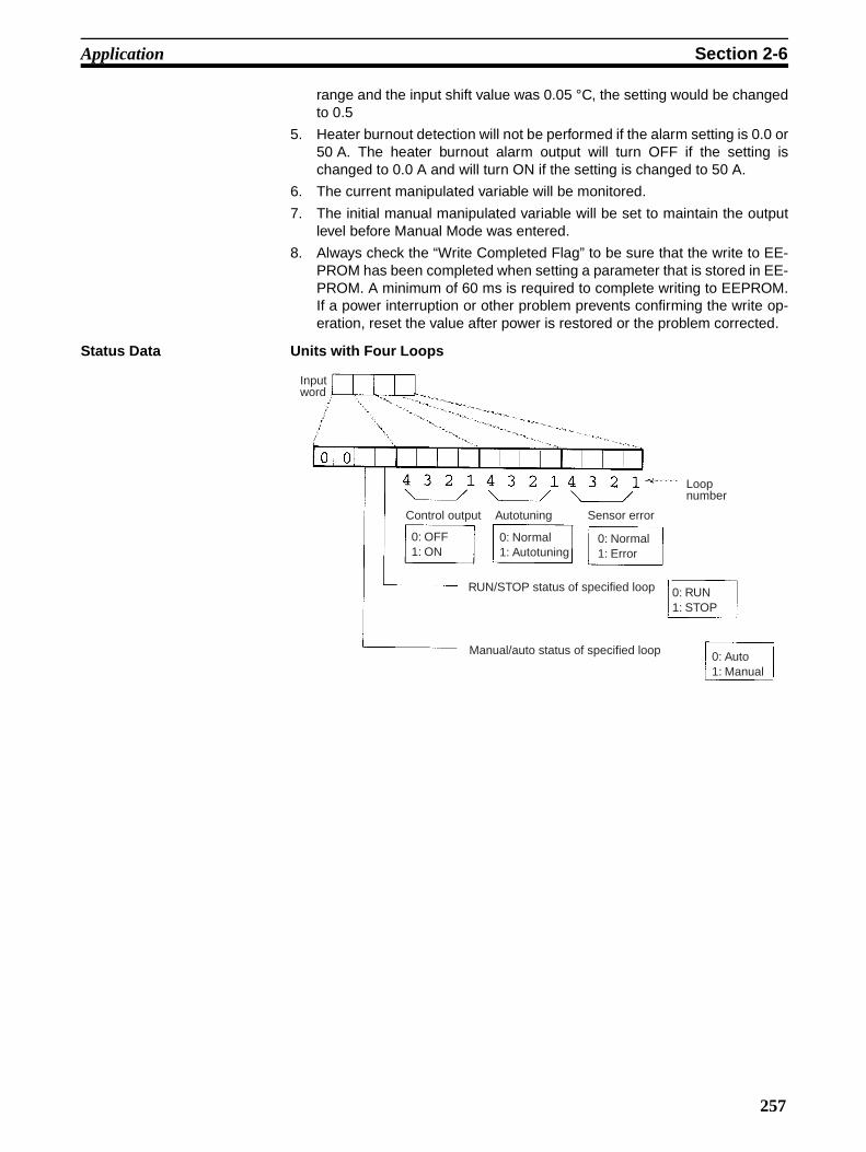
Application Section 2-6
range and the input shift value was 0.05 °C, the setting would be changedto 0.5
5. Heater burnout detection will not be performed if the alarm setting is 0.0 or50 A. The heater burnout alarm output will turn OFF if the setting ischanged to 0.0 A and will turn ON if the setting is changed to 50 A.
6. The current manipulated variable will be monitored.
7. The initial manual manipulated variable will be set to maintain the outputlevel before Manual Mode was entered.
8. Always check the “Write Completed Flag” to be sure that the write to EE-PROM has been completed when setting a parameter that is stored in EE-PROM. A minimum of 60 ms is required to complete writing to EEPROM.If a power interruption or other problem prevents confirming the write op-eration, reset the value after power is restored or the problem corrected.
Status Data Units with Four Loops
Input word
Loop number
Control output Autotuning Sensor error
0: OFF1: ON
0: Normal1: Autotuning
0: Normal1: Error
RUN/STOP status of specified loop
Manual/auto status of specified loop 0: Auto1: Manual
0: RUN1: STOP
257

Application Section 2-6
Units with Two Loops and Heater Burnout alarms
Note The RUN/STOP and manual/auto status will be given for the loop specified inthe I/O allocation command.
2-6-2 Using Operation Control CommandsThe following procedure is used to control the Unit.
1,2,3... 1. Output word: An operation control command (C@@@@) is set to specifythe loop and the operation.
2. Input word: The operation control command set in the output word will beset as a “Command Acknowledged Flag” to indicate that the command hasbeen acknowledged.
Note The value set by the previous command will be valid as soon as the next com-mand is acknowledged.
Heater burnout alarm output CT input error
0: OFF1: ON
0: Normal1: Error
Input word
Loop number
Control output Autotuning Sensor error
0: OFF1: ON
0: Normal1: Autotuning
0: Normal1: Error
RUN/STOP status of specified loop
Manual/auto status of specified loop 0: Auto1: Manual
0: RUN1: STOP
C
C
See note.
(1) (2)
60 ms max.
Output word
Input word
258

Application Section 2-6
Operation Control Commands
Note 1. The Unit will start in Auto Mode in STOP status when power is turned ON.
2. Input the loop number for @ in the command codes. “A” is used to indicateall loops. When “A” is used, the operation control command will not be ex-ecuted for any loops if even one of the four loops does not meet the writeconditions. For example, a setting error will occur (EE01) if the AUTOTUN-ING command is set when loops 1 to 3 are in RUN status and loop 4 is inSTOP status.
3. The following table shows the conditions required to execute the operationcontrol commands and the error codes that will occur when the commandcauses an error.
= Command valid
Errors: EE00 = Parameter change attempted during autotuning.
EE01 = Setting error
When “A” is used to specify all loops, the command will not be executedfor any loops if even one of the four loops does not meet execution condi-tions.
4. During manual operation, the manual manipulated variable will be outputregardless of RUN/STOP status.
Command (Set in output word; see notes 1 and 2.)
Operation Validity (See note 3.)
CCC@ (@ = 1 to 4 or A) STOP Always (STOP/RUN in Auto Mode)CCD@ (@ = 1 to 4 or A) RUN
CDC@ (@ = 1 to 4 or A) Manual Mode (See note 4.) Not valid during autotun-ing.CDD@ (@ = 1 to 4 or A) Auto Mode
CFC@ (@ = 1 to 4 or A) Autotuning (See note 5.) PID control (Not valid dur-ing Manual Mode or STOP.)
CFD@ (@ = 1 to 4 or A) Cancel autotuning PID control
CEEA (See note 6.) Writing set point to EEPROM
Always
Auto
Manual
Function DIP switch
PID
ON/OFF
Autotuning
Cannot be changed during autotuning.
RUN
STOP
Current status RUN
CCD@
STOP
CCC@
Auto ModeCDD@
Manual ModeCDC@
AT
CFC@
Cancel AT
CFD@
Write SP
CEEA
I/O allocation commands
C@@@ Write Read
Auto Mode
RUN PID AT EE00 EE00 EE00
Not AT
ON/OFF EE01 EE01
STOP EE01 EE01
Manual Mode EE01 EE01
259

Application Section 2-6
5. Parameters cannot be written and Manual Mode cannot be specified forloops for which autotuning is being executed. An error response (EE00)will be written to the input word if an attempt to do so is made.
After confirming acknowledgement of the autotuning command, changethe command code to an I/O allocation command other than one to set PIDparameters, e.g., a read–only command (C7@@).
• If the autotuning command is left in the output word, autotuning will berepeated as soon as it has been completed.
• After the autotuning command has been acknowledged, the setting forthe I/O allocation command just prior to the operation control com-mand will be valid for the output word. The following is an example ofthis.
a) An I/O allocation command is written to the output word to set the pro-portional band.
b) The autotuning command is executed and command reception ac-knowledged.
c) The set value for the proportion band (50.0) is written to the outputword. Although autotuning will set the PID parameters according to au-totuning results, here the value will be immediately changed to 50.0 asa result of the I/O allocation command set before autotuning.
6. The set point will be written to EEPROM when the CEEA command is ex-ecuted. The set point may not be written correctly if power is interruptedduring the write operation. At least 60 ms is required to complete the writeoperation after the CEEA command is executed. Always be sure to confirmthe Command Acknowledgment Flag in the input word when writing the setpoint to EEPROM.
Executing Commands from a Programming ConsoleThe following words are allocated to the Temperature Control Unit in theseexamples:
Input word = IR 001Output word = IR 100
I/O Allocation Commands The following procedure would be used to write a set point of 100 °C for loop 1and then monitor the process value for loop 1.
1,2,3... 1. Start by monitoring IR 001 and IR 100 on the Programming Console.
2. Write “C071” to the output word to specify setting the set point and readingthe process value.
“C071” will be written to the input word to acknowledge the command.
3. Write the set point for loop 1 (100 °C) to the output word.
The process value for loop 1 will be written to the input word, indicating thatthe write operation has been completed.
260

Application Section 2-6
Note If the contents of IR 100 are left unchanged, the process value inIR 001 will be updated every 500 ms.
Operation Control Commands
The following procedure would be used to switch to RUN status for all loops.
1,2,3... 1. Start by monitoring IR 001 and IR 1000 on the Programming Console.
2. Write “CCDA” to the output word to specify RUN status for all loops.
“CCDA” will be written to the input word to acknowledge the command.
261

IOTC(––) Section 2-7
2-7 IOTC(––)The IOTC(– –) instruction is supported by CX-Programmer version 2.0 or laterand CPU Unit lot number 0160 or later. The SYSMAC Support Software canalso be used by uploading the expansion instructions from a CPU Unit with alot number of 0160 or later.
2-7-1 Sending I/O Allocation CommandsIOTC(––) can be used to set, write, or monitor more than one data item at thesame time, simplifying the ladder program.
Note 1. Do not execute a macro instruction for the same Unit until execution of anypreviously executed macro instructions has been completed. Data may notbe set correctly if more than one instruction is executed at the same time.
2. The same IOTC(––) instruction will not be executed again until the inputcondition has turned OFF for at least one scan. Also, if the input conditionturns OFF and then back ON before execution has been completed, theinstruction will be executed again from the beginning.
3. Refer to 2-6-1 Communications Procedure for setting and monitor itemsand ranges.
4. Up to a maximum of 120 ms will be required to complete each I/O alloca-tion command for a normal response (timeout error: 200 ms). The totaltime to complete all commands will be a maximum of (0.12 s x refresh timex 2) x the number of commands.
C: First word of I/O command area for Temperature Control Unit
S: First source word containing write data
D: First destination for read data
First word Output word address (BCD: 0100 to 0115)
Input word address (BCD: 0001 to 0015)
Work word 1: Do not used.
Work word 2: Do not used.
Write data 0 First word
Write data 1
Write data n–1
Write data 3
Write data 2
Monitor data specified in command.Timeout error: E900Other errors: See error re-sponse codes at the end of this section.
I/O allocation commands
Loop number (1 to 4)Monitor itemSet item
IOTC (– –)
C
S
D
Number of I/O allocation commands
I/O allocation command 0
I/O allocation command 1
I/O allocation command 2
+1
+2
+3
+4
+5
+6
+7I/O allocation command 3+8
I/O allocation command n–1n+4
Specify the address of the output word allocated to the Unit.
Specify the address of the input word allocated to the Unit.
Used by the system software in the CPU Unit.
Setting: 0001 to 0099
C
C
Read data 0
Read data 1
Read data n–1
Read data 3
Read data 2
S D
.
.
....
.
.
.
262
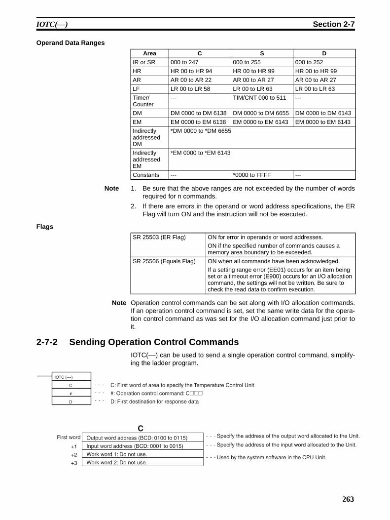
IOTC(––) Section 2-7
Operand Data Ranges
Note 1. Be sure that the above ranges are not exceeded by the number of wordsrequired for n commands.
2. If there are errors in the operand or word address specifications, the ERFlag will turn ON and the instruction will not be executed.
Flags
Note Operation control commands can be set along with I/O allocation commands.If an operation control command is set, set the same write data for the opera-tion control command as was set for the I/O allocation command just prior toit.
2-7-2 Sending Operation Control CommandsIOTC(––) can be used to send a single operation control command, simplify-ing the ladder program.
Area C S D
IR or SR 000 to 247 000 to 255 000 to 252
HR HR 00 to HR 94 HR 00 to HR 99 HR 00 to HR 99
AR AR 00 to AR 22 AR 00 to AR 27 AR 00 to AR 27
LF LR 00 to LR 58 LR 00 to LR 63 LR 00 to LR 63
Timer/ Counter
--- TIM/CNT 000 to 511 ---
DM DM 0000 to DM 6138 DM 0000 to DM 6655 DM 0000 to DM 6143
EM EM 0000 to EM 6138 EM 0000 to EM 6143 EM 0000 to EM 6143
Indirectly addressed DM
*DM 0000 to *DM 6655
Indirectly addressed EM
*EM 0000 to *EM 6143
Constants --- *0000 to FFFF ---
SR 25503 (ER Flag) ON for error in operands or word addresses.
ON if the specified number of commands causes a memory area boundary to be exceeded.
SR 25506 (Equals Flag) ON when all commands have been acknowledged.If a setting range error (EE01) occurs for an item being set or a timeout error (E900) occurs for an I/O allocation command, the settings will not be written. Be sure to check the read data to confirm execution.
IOTC (––)
C
#
D
+1
+2
+3
C
C: First word of area to specify the Temperature Control Unit
#: Operation control command: C@@@D: First destination for response data
First word Output word address (BCD: 0100 to 0115)
Input word address (BCD: 0001 to 0015)
Work word 1: Do not use.
Work word 2: Do not use.
Specify the address of the output word allocated to the Unit.
Specify the address of the input word allocated to the Unit.
Used by the system software in the CPU Unit.
263

IOTC(––) Section 2-7
Operation Control Commands
Note Refer to page 259 for details.
Operand Data Ranges
Note If there are errors in the operand or word address specifications, the ER Flagwill turn ON and the instruction will not be executed.
Flags
Sample Program 1 The IOTC(––) instruction can be used with a CQM1H CPU Unit with a lotnumber of 0160 or later.
Switch Settings The following switch settings are used.
Function DIP switch (SW1): Pins 1 and 5 turned ON = PID heating control , °C unit, 4-digit BCD
Input type DIP switch (SW2): Pins 1 and 5 turned ON = Thermocouples, 0.0 and 500.0 °C, loops 1to 4
Operations A) Power supply turned ON (STOP status, initialization).
B) Set point for loop 2 set to 100.0 °C and control period changed from 20 s(default setting) to 5 s.
C) Autotuning executed for loop 2 after RUN started.
D) RUN started and process values monitored for all loops after autotuning forloop 2 completed.
Command (Set in output word.)
Operation
CCC@ (@ = 1 to 4 or A) STOP
CCD@ (@ = 1 to 4 or A) RUN
CDC@ (@ = 1 to 4 or A) Manual Mode
CDD@ (@ = 1 to 4 or A) Auto Mode
CFC@ (@ = 1 to 4 or A) Autotuning
CFD@ (@ = 1 to 4 or A) Cancel autotuning
CEEA Writing set point to EEPROM
Specified word Input data
DResponse to operation control command
Area C D
IR or SR 000 to 250 000 to 252
HR HR 00 to HR 97 HR 00 to HR 99
AR AR 00 to AR 25 AR 00 to AR 27
LF LR 00 to LR 61 LR 00 to LR 63
DM DM 0000 to DM 6141 DM 0000 to DM 6143
EM EM 0000 to EM 6141 EM 0000 to EM 6143
Indirectly addressed DM
*DM 0000 to *DM 6155
Indirectly addressed EM
*EM 0000 to *EM 6143
SR 25503 (ER Flag) ON for error in operands or word addresses.
ON if the a memory area boundary is exceeded.
SR 25506 (Equals Flag) ON when command has been acknowledged.
264

IOTC(––) Section 2-7
Word Allocations The following words are allocated to the Temperature Control Unit.Input word: IR 001Output word: IR 100
(2) Operation Control Commands
(3) Monitoring Process Values
ContentsDM 0000 0100
(Output word)
DM 0001 0001(Input word)
CSetting
S
DM 0100 1000 (Set point: 100°C)
DM 0101 5 (Control period: 5 s)
Word MonitorD
DM 0200 Process value
DM 0201 Status
DM 0007 0100(Output word)
DM 0008 0001(Input word)
DM 0009 0000(Not used)
DM 0010 0000(Not used)
Command MeaningS
Word ResponseD
#CCD2 CCD: RUN2: Loop
#CFC2 CFC: AT2: Loop
#CCDA CCD: RUNA: All loops
(2)-1
(2)-2
(2)-3
DM 0011 0100(Output word) Word Setting
SWord Monitor
D
DM 0102 0000(For read: 0)
(1) Data for Changing the Set Point and Control Period
Word
DM 0002 0000(Not used)
DM 0003 0000(Not used)
DM 0004
DM 0005
DM 0006 C592
Word
DM 0202 2 loopsRUN
DM 0203 2 loopsAT
DM 0204 All loopsRUN
When setting several loops, increase the number ofcommands in DM0004 and set them in order from DM0005.
DM 0012 0001(Input word)
DM 0013 0000(Not used)
DM 0014 0000(Not used)
DM 0015
DM 0016 C771
DM 0017 C772
DM 0018 C773
DM 0019 C774
DM 0103 0000(For read: 0)
DM 0104 0000(For read: 0)
DM 0105 0000(For read: 0)
DM 0205 Loop 1process value
DM 0206 Loop 2process value
DM 0207 Loop 3process value
DM 0208 Loop 4process value
(C5: Control period 9: Status 2: Loop)
0004(Number of I/O
allocation commands)
(C7: Read 7: Process value 1: Loop)
(C7: Read 7: Process value 2: Loop)
(C7: Read 7: Process value 3: Loop)
(C7: Read 7: Process value 4: Loop)
0002 (Number of I/O
allocation commands)
(C0: Set point 7: Process value 2: Loop)
C072
265
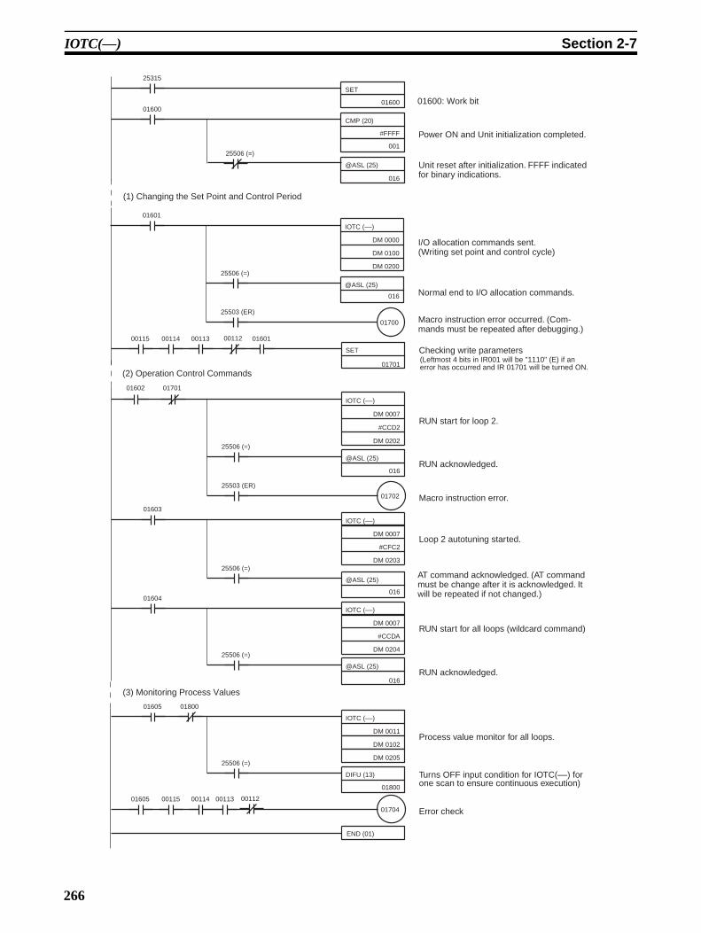
IOTC(––) Section 2-7
SET
01600
CMP (20)
#FFFF
001
@ASL (25)
016
IOTC (––)
DM 0000
DM 0100
DM 0200
@ASL (25)
016
01700
25315
01600
25506 (=)
01601
25506 (=)
25503 (ER)
SET
01701
00115 00114 00113 00112 01601
IOTC (––)
DM 0007
#CCD2
DM 0202
@ASL (25)
016
01702
01602
25506 (=)
25503 (ER)
01701
IOTC (––)
DM 0007
#CFC2
DM 0203
@ASL (25)
016
01603
25506 (=)
IOTC (––)
DM 0007
#CCDA
DM 0204
@ASL (25)
016
01604
25506 (=)
IOTC (––)
DM 0011
DM 0102
DM 0205
DIFU (13)
01800
01605
25506 (=)
01800
01704
END (01)
Power ON and Unit initialization completed.
Unit reset after initialization. FFFF indicated for binary indications.
I/O allocation commands sent.(Writing set point and control cycle)
Normal end to I/O allocation commands.
Macro instruction error occurred. (Com-mands must be repeated after debugging.)
Checking write parameters
RUN start for loop 2.
RUN acknowledged.
Macro instruction error.
Loop 2 autotuning started.
AT command acknowledged. (AT command must be change after it is acknowledged. It will be repeated if not changed.)
RUN start for all loops (wildcard command)
RUN acknowledged.
Process value monitor for all loops.
Turns OFF input condition for IOTC(––) for one scan to ensure continuous execution)
Error check
01605 00115 00114 0011200113
01600: Work bit
(1) Changing the Set Point and Control Period
(2) Operation Control Commands
(Leftmost 4 bits in IR001 will be "1110" (E) if an error has occurred and IR 01701 will be turned ON.
(3) Monitoring Process Values
266

IOTC(––) Section 2-7
Sample Program 2 The IOTC(––) instruction cannot be used with a CQM1H CPU Unit with a lotnumber earlier than 0160.
Switch Settings The following switch settings are used.
Function DIP switch (SW1): Pins 1 and 5 turned ON = PID heating control , °C unit, 4-digit BCD
Input type DIP switch (SW2): Pins 1 and 5 turned ON = Thermocouples, 0.0 and 500.0 °C, loops 1to 4
Operations For loop 1: Power supply turned ON (STOP status, initialization), set point forset to 100.0 °C, control started (RUN), and then process value monitored.
Word Allocations The following words are allocated to the Temperature Control Unit or used inprogramming.
Input word: IR 001Output word: IR 100Loop 1 process value: DM 0010Startup error check: IR 01700
SET
01600
CMP (20)
#FFFF
001
@ASL (25)
016
01700
25315
01600
25506 (=)
01601 00115 00114 0011200113
MOV (21)
#C071
100
01601
CMP (20)
#C071
001
ASL (25)
016
25506 (=)
Command reception checked.(Always confirm reception be-fore writing set value.)
Command acknowledged.
Power ON and Unit initialization checked.
I/O allocation command set.Setting: Set point for loop 1Monitor: Process value for loop 1
Power ON and Unit initialization completed.
For switching RUN only
Error Check
(Leftmost 4 bits in IR001 will be "1110" (E) if an error has occurred and IR 01701 will be turned ON.
(1) Changing the Set Point
267

IOTC(––) Section 2-7
MOV (21)
#1000
100
01602
CMP (20)
#C071
001
ASL (25)
016
25506 (=)
Set point (100.0 °) written to out-put word.
Set point reception checked.
Set point write confirmed.
00115 00114 00113 00112 01603
01701 Error check (indicated set point was written correctly).
MOV (21)
#CCD1
100
01603
CMP (20)
#CCD1
001
ASL (25)
016
25506 (=)
Operation control command: RUN (written when set point has been set correctly).
RUN reception checked.
RUN acknowledged.
01701
MOV (21)
#1000
100
01604
CMP (20)
#CCD1
001
ASL (25)
016
25506 (=)
Same set value as before (1000) allocated to output (status of previously specified I/O alloca-tion command).
Set data (1000) confirmed.
Acknowledged.
END (01)
MOV (21)
001
DM 0010
01605
Process value of loop 1 moved to DM 0010.
(2) Operation Control Commands
(3) Monitoring Process Values
268

Troubleshooting Section 2-8
2-8 Troubleshooting
Error Priority
The error code with the highest priority will be set then more than one erroroccurs at the same time. The errors are given in order of priority in the abovetable.
Error Control output Remedy
Watchdog timer error “EEEE” set in input word.
OFF for all outputs. Turn the power supply OFF and then back ON. If the error persists, replace the Unit.
RAM read/write error “E100” set in input word.
EEPROM error “E120” set in input word.
Parameter change dur-ing autotuning
“EE00” set in input word.
Normal operation will continue.
Set parameter after autotuning has been completed.
Setting range error “EE01” set in input word.
Reset the setting to within the proper range.
Sensor error “E400” set in input word when process value is monitored for a loop.
Auto Mode: OFF for control loop with error.Manual Mode: Opera-tion will continue with manual output level.
Check the connections to the input sensor and cold junction compensator. Check the sensor for broken or shorted wir-ing.Check the sensor connections to be sure they have not been reversed.
Be sure the correct sensor and compensat-ing lead are connected.Be sure the input temperature range has not been exceeded.Check the cold junction compensator to be sure it is connected properly.
Be sure the sensor and input type settings agree.Be sure the input type DIP switch and the function DIP switch settings are correct.
CT input error “E500” set in input word when heater current is monitored for a loop.
The heater burnout alarm output will main-tain the same status as before the CT input error.
The current is 55 A or higher. Reduce the heater current to below 55 A.
Timeout error (for IOTC(––) instruction)
“E900” is output to the destination word (D) for the IOTC(––) instruc-tion.
Normal operation will continue.
The set value for the I/O allocation com-mand will not have been written. Repeat the setting.
269
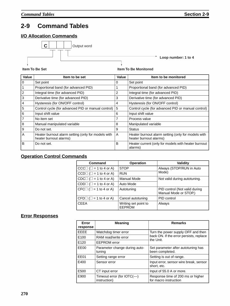
Command Tables Section 2-9
2-9 Command Tables
I/O Allocation Commands
Operation Control Commands
Error Responses
Value Item to be set Value Item to be monitored
0 Set point 0 Set point
1 Proportional band (for advanced PID) 1 Proportional band (for advanced PID)
2 Integral time (for advanced PID) 2 Integral time (for advanced PID)
3 Derivative time (for advanced PID) 3 Derivative time (for advanced PID)
4 Hysteresis (for ON/OFF control) 4 Hysteresis (for ON/OFF control)
5 Control cycle (for advanced PID or manual control) 5 Control cycle (for advanced PID or manual control)
6 Input shift value 6 Input shift value
7 No item set 7 Process value
8 Manual manipulated variable 8 Manipulated variable
9 Do not set. 9 Status
A Heater burnout alarm setting (only for models with heater burnout alarms)
A Heater burnout alarm setting (only for models with heater burnout alarms)
B Do not set. B Heater current (only for models with heater burnout alarms)
Command Operation Validity
CCC@ (@ = 1 to 4 or A) STOP Always (STOP/RUN in Auto Mode)CCD@ (@ = 1 to 4 or A) RUN
CDC@ (@ = 1 to 4 or A) Manual Mode Not valid during autotuning.
CDD@ (@ = 1 to 4 or A) Auto Mode
CFC@ (@ = 1 to 4 or A) Autotuning PID control (Not valid during Manual Mode or STOP.)
CFD@ (@ = 1 to 4 or A) Cancel autotuning PID control
CEEA Writing set point to EEPROM
Always
C
Item To Be Set Item To Be Monitored
Output word
Loop number: 1 to 4
Error response
Meaning Remarks
EEEE Watchdog timer error Turn the power supply OFF and then back ON. If the error persists, replace the Unit.
E100 RAM read/write error
E120 EEPROM error
EE00 Parameter change during auto-tuning
Set parameter after autotuning has been completed.
EE01 Setting range error Setting is out of range.
E400 Sensor error Input error, sensor wire break, sensor short, etc.
E500 CT input error Input of 55.0 A or more.
E900 Timeout error (for IOTC(––) instruction)
Response time of 200 ms or higher for macro instruction
270

SECTION 3CQM1-TC00@/TC10@ Temperature Control Units
This section describes the features and operation of the CQM1-TC00@/TC10@ Temperature Control Units.
3-1 Features and Word Allocations . . . . . . . . . . . . . . . . . . . . . . . . . . . . . . . . . . . . 272
3-1-1 Features. . . . . . . . . . . . . . . . . . . . . . . . . . . . . . . . . . . . . . . . . . . . . . . 272
3-1-2 Word Allocations . . . . . . . . . . . . . . . . . . . . . . . . . . . . . . . . . . . . . . . 272
3-2 Specifications . . . . . . . . . . . . . . . . . . . . . . . . . . . . . . . . . . . . . . . . . . . . . . . . . 273
3-3 Nomenclature . . . . . . . . . . . . . . . . . . . . . . . . . . . . . . . . . . . . . . . . . . . . . . . . . 274
3-3-1 Control Modes . . . . . . . . . . . . . . . . . . . . . . . . . . . . . . . . . . . . . . . . . 275
3-3-2 Switch Settings . . . . . . . . . . . . . . . . . . . . . . . . . . . . . . . . . . . . . . . . . 275
3-4 Wiring . . . . . . . . . . . . . . . . . . . . . . . . . . . . . . . . . . . . . . . . . . . . . . . . . . . . . . . 276
3-5 Application Examples . . . . . . . . . . . . . . . . . . . . . . . . . . . . . . . . . . . . . . . . . . . 277
3-5-1 Basic Program for Temperature Control Unit . . . . . . . . . . . . . . . . . 277
3-5-2 Run/Stop and Error Processing Program . . . . . . . . . . . . . . . . . . . . . 278
3-5-3 ON/OFF Control . . . . . . . . . . . . . . . . . . . . . . . . . . . . . . . . . . . . . . . . 280
3-5-4 Advanced PID Control . . . . . . . . . . . . . . . . . . . . . . . . . . . . . . . . . . . 281
3-6 AT (Expansion Mode) . . . . . . . . . . . . . . . . . . . . . . . . . . . . . . . . . . . . . . . . . . . 282
3-6-1 Manual Settings (Expansion Mode) . . . . . . . . . . . . . . . . . . . . . . . . . 283
3-6-2 Set Value Read . . . . . . . . . . . . . . . . . . . . . . . . . . . . . . . . . . . . . . . . . 285
3-6-3 Set Value Write . . . . . . . . . . . . . . . . . . . . . . . . . . . . . . . . . . . . . . . . . 286
3-7 Troubleshooting . . . . . . . . . . . . . . . . . . . . . . . . . . . . . . . . . . . . . . . . . . . . . . . 287
271
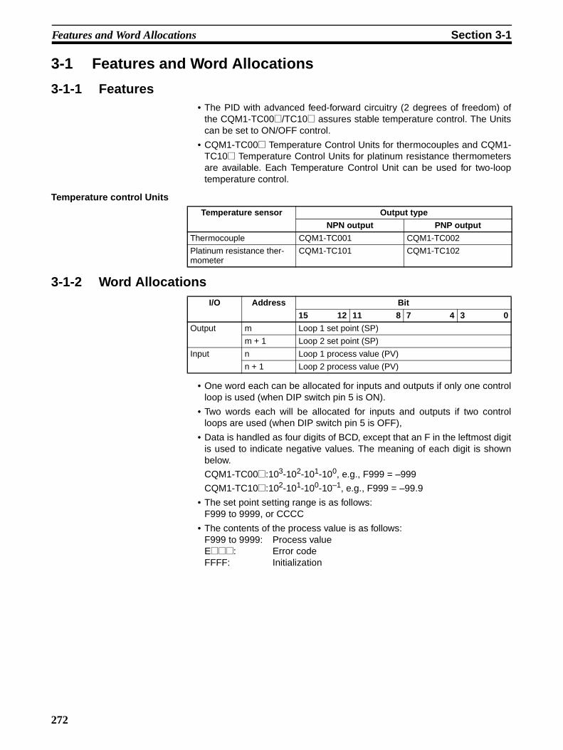
Features and Word Allocations Section 3-1
3-1 Features and Word Allocations
3-1-1 Features• The PID with advanced feed-forward circuitry (2 degrees of freedom) of
the CQM1-TC00@/TC10@ assures stable temperature control. The Unitscan be set to ON/OFF control.
• CQM1-TC00@ Temperature Control Units for thermocouples and CQM1-TC10@ Temperature Control Units for platinum resistance thermometersare available. Each Temperature Control Unit can be used for two-looptemperature control.
Temperature control Units
3-1-2 Word Allocations
• One word each can be allocated for inputs and outputs if only one controlloop is used (when DIP switch pin 5 is ON).
• Two words each will be allocated for inputs and outputs if two controlloops are used (when DIP switch pin 5 is OFF),
• Data is handled as four digits of BCD, except that an F in the leftmost digitis used to indicate negative values. The meaning of each digit is shownbelow.
CQM1-TC00@:103-102-101-100, e.g., F999 = –999
CQM1-TC10@:102-101-100-10–1, e.g., F999 = –99.9
• The set point setting range is as follows:F999 to 9999, or CCCC
• The contents of the process value is as follows:F999 to 9999: Process valueE@@@: Error codeFFFF: Initialization
Temperature sensor Output type
NPN output PNP output
Thermocouple CQM1-TC001 CQM1-TC002
Platinum resistance ther-mometer
CQM1-TC101 CQM1-TC102
I/O Address Bit
15 12 11 8 7 4 3 0
Output m Loop 1 set point (SP)
m + 1 Loop 2 set point (SP)
Input n Loop 1 process value (PV)
n + 1 Loop 2 process value (PV)
272

Specifications Section 3-2
3-2 SpecificationsGeneral Specifications The general specifications of the CQM1-TC00@/TC10@ conform to those of
the CQM1H/CQM1 Series.
Performance Specifications
Dimensions All dimensions are in millimeters.
Item Specification
Input sensors and set point ranges
Sensors used with thermo-couples
CQM1-TC00@ K: –200 to 1,300 °C (–300 to 2,300 °F)CQM1-TC00@ J: –100 to 850 °C (–100 to 1,500 °F)
Sensors used with platinum resistance thermometers
CQM1-TC10@ JPt100: –99.9 to 450.0 °C (–99.9 to 800.0 °F)CQM1-TC10@ Pt100: –99.9 to 450.0 °C (–99.9 to 800.0 °F)
Number of control loops Two (either 1 or 2 loops can be used)
Control output NPN or PNP output with short-circuit protection
Power supply voltage: 24 VDC +10%/–15%
Maximum switching capacity: 100 mA per output
Leakage current: 0.3 mA max.Residual voltage: 3.0 V max.
Control mode ON/OFF or advanced PID control (2 degrees of freedom)
Setting and display accuracy CQM1-TC00@: (Process value ±1% or ±3 °C, whichever is larger) ±1 digit max.
CQM1-TC10@: (Process value ±1% or ±2 °C, whichever is larger) ±1 digit max.
Hysteresis 0.8 °C/°FProportional band 40.0 °C/°FDerivative time 240 s
Integral time 40 s
Control period 20 s
Sampling period 1 s
Output refresh period 1 s
Current consumption 220 mA max. at 5 VDC
Weight 200 g max.
Dimensions 32 x 110 x 107 mm (W x H x D)
273
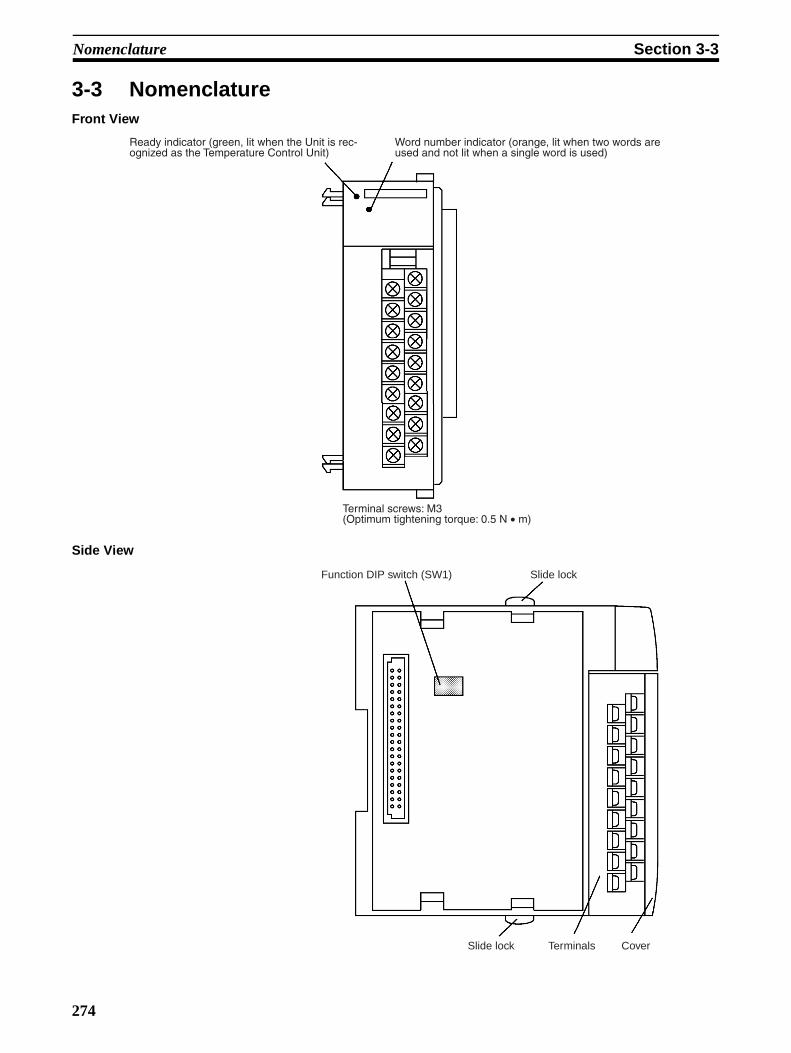
Nomenclature Section 3-3
3-3 NomenclatureFront View
Side View
Ready indicator (green, lit when the Unit is rec-ognized as the Temperature Control Unit)
Word number indicator (orange, lit when two words are used and not lit when a single word is used)
Terminal screws: M3(Optimum tightening torque: 0.5 N • m)
Slide lockFunction DIP switch (SW1)
CoverTerminalsSlide lock
274

Nomenclature Section 3-3
3-3-1 Control ModesControl is performed independently for each control loop based on the setpoint data. The relationship between the set point data and the control opera-tion is shown in the following table.
If the temperature exceeds the range from –999 to 9999, the process valuedata in the Temperature Controller will be frozen at –999 or 9999 and the datawill be maintained at F999 or 9999, respectively.
The process value data will be set to FFFF during initialization; do not readthe data as the process value at this time.
Short-circuit Protection If the output is shorted, short-circuit protection will operate, turning the outputOFF. To reset the short-circuit protection, either turn off the power supply orset the set point data to CCCC to stop control operation.
3-3-2 Switch Settings1,2,3... 1. Set the function DIP switch pins (SW1) before connecting the Temperature
Control Unit to the other Units of the PC.
2. All pins on the DIP switch are factory-set to OFF.
3. Use a pen tip or other pointed object to set the pins of the DIP switch.
Control Operation
Reverse Control Used for heating control with heaters. If the temperature is lower than the settemperature (i.e., the temperature has negative deviation), the output of theheaters will be increased.
Normal Control Used for suppressing excessively high temperature with cooling water. If thetemperature is higher than the set temperature (i.e., the temperature has pos-itive deviation), the output of the cooling water will be increased.
Set point Control operation
F999 to 9999 Normal temperature control performed.
CCCC Control stopped.
Other settings Temperature control performed according to the most recent valid set point data. The PV will be EE01.
Pin Function OFF ON
1 Control mode ON/OFF Advanced PID
2 Control operation Reverse (heating con-trol)
Normal (cooling control)
3 Temperature scale °C °F4 Input sensor TC00@: K
TC10@: JPt100
TC00@: J
TC10@: Pt100
5 Number of control loops (control points)
Two loops One loop
6 Control period 20 s 2 s
275

Wiring Section 3-4
3-4 Wiring
Wiring
Note When using only one control loop, short-circuit the loop 2 input terminals. Ifused with the terminals open, “E400” (PV error) will be read into the CPU Unitfor approximately 10 seconds when power is turned ON.
• Do not touch or remove the cold junction compensator. (CQM1-TC001/TC002)
• Connect to loop 1 terminals and turn ON pin 5 on SW1 when using onlyone control loop.
• Use the input sensor set on the function DIP switch.
CQM1-TC001 CQM1-TC002
LCOM
+ DC
+ 24 VDC
L L L
Loop 1 OUTLoop 2
OUT
Loop 1 TC
Loop 2 TC
–
+
–
+
Cold junctioncompensator
Loop 1 TC
Loop 2 TC
–
+
–
+
Cold junctioncompensator
Loop 1 OUTLoop 2
OUT
0 VCOM
+ 24 VDC
CQM1-TC101 CQM1-TC102
B
L L L L
A
COM+ DC
+ 24 VDC
Loop 1 OUTLoop 2
OUT
Loop 1 OUTLoop 2
OUT
0 VCOM
+ 24 VDC
B
B
A
B
Loop 1 Pt
Loop 2 Pt
B
A
B
B
A
B
Loop 1 Pt
Loop 2 Pt
276

Application Examples Section 3-5
Output Interface
Output Characteristeics
Output Circuits
3-5 Application Examples3-5-1 Basic Program for Temperature Control UnitOperation (for Control Loop 1 Only)
The contents of DM 0000 are written to the Temperature Control Unit as theset point.
The process value is read from the Temperature Control Unit and written toDM 0001. If an error has occurred, however, the value written to DM 0001 willbe treated as an error code.
Word/Bit Allocations (for Control Loop 1 Only)
Maximum switching capability 100 mA, 24 VDC +10%/–15%
Leakage current 0.3 mA max.
Residual voltage 3.0 V max.
External supply voltage 15 mA min., 24 VDC +10%/–15% (exclud-ing load current)
+DC
OUT
COM
COM
OUT
0 V
CQM1-TC 01 (NPN) CQM1-TC 02 (PNP)
Temperature Control Unit input word IR 001
Temperature Control Unit output word IR 100
Set point storage word DM 0000
Process value storage word DM 0001
Initialization End Flag IR 01600
CMP(20)
#FFFF
001
END(01)
25313
01600
25506
MOV(21)
DM0000
100
01600
MOV(21)
001
DM0001
Always ON Flag
(=)
If the process value (contents of IR 001) is not FFFF, IR 01600 is turned ON to indicate that initialization has been completed.
If IR 01600 is ON, the contents of DM 0000 will be written as the set point to IR 100.
If IR 01600 is ON, the contents of IR 001 will be read to DM 0001 as the process value.
The contents of IR 001 is compared to FFFF to confirm that the Temperature Control has com-pleted initialization processing. (See note 3)
277

Application Examples Section 3-5
Note 1. Write a program for control loop 2 in the same way.
2. The contents of both DM 0000 and DM 0001 are four-digit BCD except thatan F in the leftmost digit is used to indicate negative values. The meaningof each digit is shown below.CQM1-TC00@: 103-102-101-100, e.g., F999 = –999CQM1-TC10@: 102-101-100-10–1, e.g., F999 = –99.9
3. The process value data will be set to FFFF during initialization; do not readthe data as the process value at this time.
DM 0000 Write a value in the following ranges to DM 0000 according to the sensor to beused.
3-5-2 Run/Stop and Error Processing ProgramOperation (for Control Loop 1 Only)
The contents of DM 0000 are written to the Temperature Control Unit as theset point.
The process value is read from the Temperature Control Unit and written toDM 0001. If an error has occurred, however, the value written to DM 0001 willbe treated as an error code.
If the CQM1-TC00@/TC10@ in operation has an error, the condition of theerror is stored as error status.
Temperature control is enabled or disabled by turning the RUN/STOP bit ONor OFF (loop 1 Only).
Word/Bit Allocations (for Control Loop 1 Only)
Model Sensor Range
TC00@ for thermocouples K –200 to 1,300 °C (F200 to 1300)–300 to 2,300 °F (F300 to 2300)
J –100 to 850 °C (F100 to 0850)–100 to 1,500 °F (F100 to 1500)
TC10@ for platinum resistance ther-mometers
JPt100 –99.9 to 450.0 °C (F999 to 4500)–99.9 to 800.0 °F (F999 to 8000)
Pt100 –99.9 to 450.0 °F (F999 to 4500)–99.9 to 800.0 °F (F999 to 8000)
Item Word Remarks
Temperature Control Unit input word (loop 1)
IR 001 ---
Temperature Control Unit out-put word (loop 1)
IR 100 ---
Set point storage word DM 0000 ---
Process value storage word DM 0001 ---
Initialization End Flag IR 01600 ---
Error status IR 017 IR 01700: ON for input sensor error.IR 01701: ON for setting range error.
IR 01702: ON for Watchdog timer, RAM, Read/Write, or EEPROM error.
IR 01715: ON for any error.
RUN/Stop bit IR 01800 Control operations will be run when IR 01800 is turned OFF and will be stopped when it is turned ON.
278
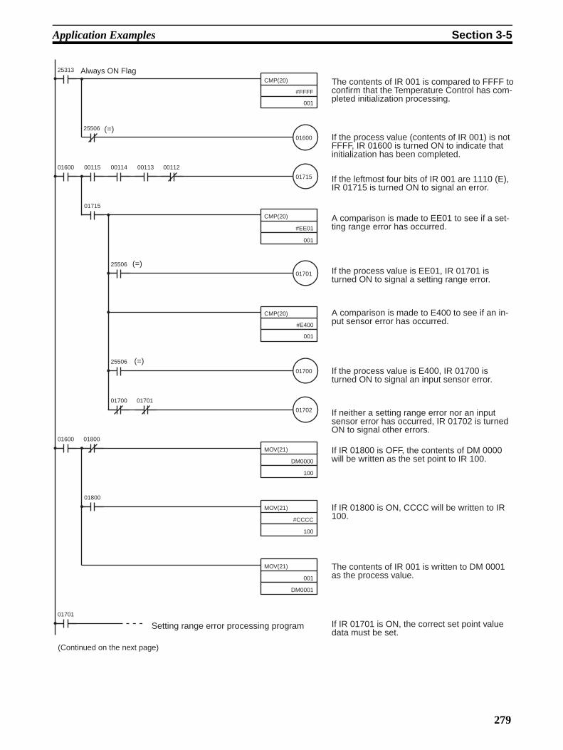
Application Examples Section 3-5
CMP(20)
#FFFF
001
25313
01600
25506
CMP(20)
#EE01
001
Always ON Flag
(=)
01715
01600 00115 00114 00113 00112
01715
01701
CMP(20)
#E400
001
25506
01700
25506
01702
01700 01701
(=)
(=)
The contents of IR 001 is compared to FFFF to confirm that the Temperature Control has com-pleted initialization processing.
If the process value (contents of IR 001) is not FFFF, IR 01600 is turned ON to indicate that initialization has been completed.
If the leftmost four bits of IR 001 are 1110 (E), IR 01715 is turned ON to signal an error.
A comparison is made to EE01 to see if a set-ting range error has occurred.
If the process value is EE01, IR 01701 is turned ON to signal a setting range error.
A comparison is made to E400 to see if an in-put sensor error has occurred.
If the process value is E400, IR 01700 is turned ON to signal an input sensor error.
If neither a setting range error nor an input sensor error has occurred, IR 01702 is turned ON to signal other errors.
MOV(21)
DM0000
100
01600 01800
MOV(21)
#CCCC
100
MOV(21)
001
DM0001
01800
01701
If IR 01800 is OFF, the contents of DM 0000 will be written as the set point to IR 100.
If IR 01800 is ON, CCCC will be written to IR 100.
The contents of IR 001 is written to DM 0001 as the process value.
If IR 01701 is ON, the correct set point value data must be set.
Setting range error processing program
(Continued on the next page)
279

Application Examples Section 3-5
Note If more than one error occurs at the same time, the error with the highest pri-ority will be output as the process value data. Error priority from highest to lowest is as follows:Watchdog timer > RAM read/write > EEPROM > Setting range > Input sensor
3-5-3 ON/OFF ControlThe default value of the ON/OFF control hysteresis (i.e., SW1-1 is turnedOFF) of the Temperature Control Unit is 0.8 °C/°F. Refer to 3-6-1 Manual Set-tings (Expansion Mode) for details on changing the hysteresis.
The following table lists the effectiveness of hysteresis adjustment.
01700
01702
END(01)
Input sensor error processing program
Watchdog timer, RAM read/write, and EEPROM error processing program
If IR 01700 is ON, check the connections to the input sensor and cold junction compensator. If connections are correct for both the input sen-sor and cold junction compensator, replace the Unit.
If IR 01702 is ON, turn power OFF and then back on. If the error persists, replace the Unit.
Adjustment Effect
Reduce the value • The hunting amplitude becomes small.• When the process value is fluttering near the set point, the
output becomes unstable.• The period between the output turned ON and turned OFF
becomes short.
Increase the value • The hunting amplitude becomes large.• The output near the set point becomes stable.• The period between the output turned ON and turned OFF
becomes long.
280

Application Examples Section 3-5
If ON/OFF control is used, in the following graph hunting, the amplitude andperiod of which depend on the controlled object, will occur even if the hystere-sis of the Temperature Control Unit is adjusted. If the hunting is not within thepermissible range determined by the user, use advanced PID control.
3-5-4 Advanced PID ControlIf advanced PID control (i.e., SW1-1 is turned ON) is selected, the Tempera-ture Control Unit will operate with the P value fixed to 40.0, the I value fixed to240, and the D value fixed to 40.
The user’s required control may not be performed with the default PID param-eters. In this case, refer to 3-6 AT (Expansion Mode) and 3-6-1 Manual Set-tings (Expansion Mode) to set the most suitable PID parameters.
Even if the most suitable PID parameters are set, hunting may occur if thecontrol period is long. In this case, set SW1-6 according to the characteristicsof the controlled object. If SW1-6 is turned OFF, the control period will be 20 sand if SW1-6 is turned ON, the control period will be 2 s.
When the control period is set to 2 s (i.e., SW1-6 is turned ON), it can be setto 1 through 99 s freely. Refer to 3-6-1 Manual Settings (Expansion Mode) fordetails.
SP
PV
MV
100%
0%
Temperature
Hysteresis
Time
281

AT (Expansion Mode) Section 3-6
3-6 AT (Expansion Mode)To enter the Expansion Mode, change the connection of jumper connectorfrom 2-3 to 1-2.
By executing AT (auto-tuning), the most suitable PID parameters can be set.
The AT function allows PID parameter calculation by recognizing the charac-teristics of the object from the waveform (amplitude and period) to be gener-ated when ON/OFF control is executed (refer to the following diagram). ThePID parameters obtained will be refreshed automatically, and after completionof auto-tuning, the Temperature Control Unit will start operating using theparameters.
SW1
MODE TEST
Change this connection.
Do not change this connection. This is for factory-use only.
MODE
MODE
1 3
1 3
Default setting
Expansion Mode
Change the connection to 1-2
Left-side View of the Unit
SP
0
Auto-tuning starts Auto-tuning completes
Limit period with 100% controlled variation width
282

AT (Expansion Mode) Section 3-6
Auto-tuning can be started by taking the following procedure on the Program-ming Console.
Default: SP = 100 °C and PV = 98 °C
Write the AT start code “CF00” to the output word of the relevant loop andconfirm that the input word will become CF00.
Set SP to 100 °C again.
To cancel auto-tuning, use the code “CF01” instead and follow the above pro-cedure.
Note 1. To put the Temperature Control Unit into expansion mode, change thejumper pin on the side of the Unit from 2 and 3 to 1 and 2.
2. Auto-tuning is not available if the half period exceeds 9999 s (approximate-ly 2 hours 45 minutes). If the half cycle exceeds 9999 s, no measurementis possible and the Temperature Control Unit will restart auto-tuning auto-matically.
3. If the output word data is left as CF00, auto-tuning will be repeated. Besure to return it to the set value.
3-6-1 Manual Settings (Expansion Mode)When the Temperature Control Unit is turned ON, the SP will be allocated tothe output word and the PV will be allocated to the PV word. By changing thecontents of the allocation, the following six set values can be read or written.
Parameter Setting range Unit Default Remarks
Set point –999 to 9,999 °C/°F 0 ---
Proportional band 0.1 to 999.9 °C/°F 40.0 ---
Integral time 0 to 3999 Seconds 240 ---
Derivative time 0 to 3999 Seconds 40 ---
Hysteresis 0.1 to 999.9 °C/°F 0.8 ---
Control period 1 to 99 Seconds 2 When SW1-6 is set to ON, the value can be changed. In this case, the default is “2.”
Input shift value –99.9 to 999.9 °C/°F 0.0 ---
Process value –999 to 9,999 °C/°F --- Read-only
Manipulated variable 0.1 to 100.0 % --- Read-only
Status --- --- --- Read-only
283

AT (Expansion Mode) Section 3-6
Write an allocation change code to the output for allocation changes. The fol-lowing is the format of the allocation change code.
Example If the user wants to write derivative time to the output word and a controlperiod to the input word, input C350 as the allocation change code to be writ-ten.
Note When the Temperature Control Unit is turned on, the allocation change code“C070” will be written.
Use the following procedure on the Programming Console for allocationchanges.
Default: SP = 100 °C and PV = 98 °C
Write the allocation change code “C350” to the output word of the relevantloop and confirm that the input word will become C350.
Write the derivative time to the output word so that the control period will beread from the input word.
Note To put the Temperature Control Unit into expansion mode, change the jumperpin on the side of the Unit from 2 and 3 to 1 and 2.
Output side Input side Enabled
No. Contents No. Contents
0 Set point 0 Set point Always enabled.
1 Proportional band 1 Proportional band For PID control.
2 Integral time 2 Integral time For PID control.
3 Derivative time 3 Derivative time For PID control.
4 Hysteresis 4 Hysteresis For ON/OFF control.
5 Control period 5 Control period For PID control.
6 Input shift 6 Input shift Always enabled.
7 (Not selectable) 7 Process value Always enabled.
8 (Not selectable) 8 Manipulated variable Always enabled.
9 (Not selectable) 9 Status Always enabled.
C 0
Data number on the input side (select from the following table)
Data number on the output side (select from the following table)
284

AT (Expansion Mode) Section 3-6
Data Status
Note The data status is updated every 200 ms.
3-6-2 Set Value ReadExecute the following on the Programming Console for loops 1 and 2.
1,2,3... 1. Read the proportional band.
Default: SP = 100 °C and PV = 98 °C
Write the allocation change code “C010” to the output word of the relevantloop.
Confirm that the input word of the relevant loop will become C010.
Write the set point to the output word of the relevant loop.
Record the value read from the input word of the relevant loop as the pro-portional band.
2. Read the integral time.
Refer to the above procedure and replace the allocation change code“C010” with “C020” and write it as the integral time.
3. Read the derivative time.
0 0 0 0Word
Loop 1: Sensor error
Loop 2: Sensor error
Not used
Loop 1: Auto-tuning (AT) execute
Loop 2: Auto-tuning (AT) execute
Loop 1: Control output ON
Loop 2: Control output ON
Not used
Control period: SW1-6 ON.
Number of loops: SW1-5 ON
Input sensor: SW1-4 ON
Temperature scale: SW1-3 ON
Control operation: SW1-2 ON
Control mode: SW1-1 ON
Not used
The following are set to "1" under the conditions given.
285

AT (Expansion Mode) Section 3-6
Refer to the above procedure and replace the allocation change code“C010” with “C030” and write it as the derivative time.
4. Read the hysteresis.
Refer to the above procedure and replace the allocation change code“C010” with “C040” and write it as the hysteresis.
5. Read the control period.
Refer to the above procedure and replace the allocation change code“C010” with “C050” and write it as the control period.
6. Read the input shift.
Refer to the above procedure and replace the allocation change code“C010” with “C060” and write it as the input shift.
7. Read the manipulated variable.
Refer to the above procedure and replace the allocation change code“C010” with “C080” and write it as the manipulated variable.
8. Read the status.
Refer to the above procedure and replace the allocation change code“C010” with “C090” and write it as the status.
9. Return to the original status.
Refer to the above procedure and replace the allocation change code“C010” with “C070” and execute so that the Temperature Control Unit willreturn to the original status (i.e., the status when turning on the Tempera-ture control Unit).
3-6-3 Set Value WriteExecute the following on the Programming Console for loops 1 and 2.
1,2,3... 1. Write the proportional band.
Default: SP = 100 °C and PV = 98 °C
Write the allocation change code “C110” to the output word of the relevantloop.
Confirm that the input word of the relevant loop will become C110.
Write the set point to the output word of the relevant loop.
Confirm that the value read from the input word of the relevant loop is thevalue that has been set
c100 c001C110 0098
c100 c001C110 C110
c100 c0010400 C110
c100 c0010400 0400
286

Troubleshooting Section 3-7
2. Write the integral time.
Refer to the above procedure and replace the allocation change code“C110” with “C220” and write it as the integral time.
3. Write the derivative time.
Refer to the above procedure and replace the allocation change code“C110” with “C330” and write it as the derivative time.
4. Write the hysteresis.
Refer to the above procedure and replace the allocation change code“C110” with “C440” and write it as the hysteresis.
5. Write the control period.
Refer to the above procedure and replace the allocation change code“C110” with “C550” and write it as the control period.
6. Write the input shift.
Refer to the above procedure and replace the allocation change code“C110” with “C660” and write it as the input shift.
7. Return to the original status.
Refer to the above procedure and replace the allocation change code“C110” with “C070” and execute and then write the set point so that theTemperature Control Unit will return to the original status (i.e., the statuswhen turning on the Temperature Control Unit).
Note The IOTC(––) instruction can be used with CQM1H CPU Units with lot num-ber 0160 or later. If the ALLOCATE I/O command is sent, up to 250 ms maybe required to received a response just after power is turned ON. Program theCPU Unit so that this command is not sent within the first 100 ms after poweris turned ON.
3-7 TroubleshootingError Control output Remedy
Watchdog timer error “EEEE” PV data for control loops 1 and 2.
Will be OFF for control loops 1 and 2.
Turn the power supply off and then back on. If the error persists, replace the Unit.
RAM read/write error “E100” PV data for con-trol loops 1 and 2.
EEPROM error “E120” PV data for con-trol loops 1 and 2.
Setting range error “EE01” PV data for con-trol loops with error.
Control will be normal. Reset the SV to within the proper range.
Sensor error “E400” PV data for con-trol loops with error.
Will be OFF for control loop with error.
Check the connections to the input sensor and cold junction compensator. If connections are correct for both the input sensor and cold junc-tion compensator, replace the Unit.
287


289
Revision History
A manual revision code appears as a suffix to the catalog number on the front cover of the manual.
The following table outlines the changes made to the manual during each revision. Page numbers refer to theprevious version.
Revision code Date Revised content1 December 1993 Original production
2 June 1994 Parts IV, V, and VI added.Page xi: Parts IV, V, and VI introductions added.Page 25: Input and output words were opposite to each other and have been corrected.Page 45: COM 1 corrected to CQM1 in the bottom diagram.
3 February 1995 Part I B7A Interface Units has been completely changed to reflect the addition of new models. Part II G730 Interface Units added.Sections 5, 6, and 7 have been added to Part VII Temperature Control Units.Pages 22, 25: Switch diagram changed.Pages 24, 38, 130: Terminal screw size added to the diagram.Page 28: Note 1 at the bottom of the page rewritten.Pages 29, 77, 145: Dimensions in the table corrected. Page 29, 53, 54: Dimensions added to page.Pages 53, 77: Accuracy specification corrected.Page 77: Internal current consumption corrected.Page 128: Third paragraph deleted since the current detection function is not provided.Page 131: “PID with feed-forward circuitry” corrected to “Advanced PID” in the table.
4 October 1995 Part VII Linear Sensor Interface Unit added.Pages 6, 7: Note 3 and caution added.Page 23: Minimum input time and note 4 added to the table.Page 87: Input circuit added for the Analog Input Unit.Page 177: A table of available commands and functions added.Page 189: Wording of description for I/O words corrected.Page 204: Wording of note corrected.
4A July 1996 Pages 66, 70: Note on EC directives added.Page 78: CQM1-PA216 added.Page 116: Reference for polygonal line conversion corrected.
5 June 1997 Page 5, 32, 62, 77, 78, 126, 170: CQM1-CPU4@ model numbers changed to [email protected] 31: Number of I/O points changed from 192 to 256.Page 63, 64: C200HX/HG/HE added to the PC column of the table. “(F)” added to C1000H and C500.Page 112, 113: Wiring diagrams changed for 3-1-2 Wiring and 3-1-3 Terminal Arrange-ment.Page 138, 139, 143: Force measurements changed to SI units.Page 157: Enclosure rating in the tables corrected.Page 261: Setting and display accuracy specifications corrected.
6 November 1998 Added Precautions to the beginning of the manual.Pages 10 to 14, 19, 34 to 36, 40, 41, 234: Added tightening torque value.Page 108: Added Front View under 2-1 Nomenclature.Page 186: Changed tightening torque value.Page 238: Added a note to the wiring diagram.
7 September 1999 Information relating to CQM1H added.
Cat. No. W238-E1-10
Revision code

Revision History
8 August 2000 CQM1-TC20@/TC30@ were added to part VIII and part VIII was restructured. The follow-ing specific changes were also made.Page xvi: Additions made to safety precautions. Pages xvii and xviii: Additions and changes made to application precautions.Page 232: First bullet in features rewritten. Page 238: Bullet added to the bottom of the page. Page 239: External supply voltage specification modified. Page 244: IR 01700 condition in middle of diagram changed to NC condition.Page 245: Program comments changed. Page 251: Parameters added to table. Page 252: Table modified. Page 257: A note about the use of IOTC added.Page 261: Control output specifications added.
09 December 2002 Pages 28, 32, 35, 50: Minor changes made to manual references.Page 35, 36: Minor changes made to model numbers.Pages 256, 257: “ASL” changed to “@ASL”.
10 November 2003 Page 242: “101” corrected to “102.”Page 244: Model number corrected in table. Page 264: Changes made to description of operations.Page 265: Changes made to charts showing word allocations.Pages 266 to 268: Layout changes made to ladder diagrams.
Revision code Date Revised content
290

OMRON CORPORATIONFA Systems Division H.Q.66 MatsumotoMishima-city, Shizuoka 411-8511JapanTel: (81)55-977-9181/Fax: (81)55-977-9045
Regional Headquarters
OMRON EUROPE B.V.Wegalaan 67-69, NL-2132 JD HoofddorpThe NetherlandsTel: (31)2356-81-300/Fax: (31)2356-81-388
OMRON ELECTRONICS LLC1 East Commerce Drive, Schaumburg, IL 60173U.S.A.Tel: (1)847-843-7900/Fax: (1)847-843-8568
OMRON ASIA PACIFIC PTE. LTD.83 Clemenceau Avenue, #11-01, UE Square,Singapore 239920Tel: (65)6835-3011/Fax: (65)6835-2711

Cat. No.
This ma
Authorized Distributor:
W238-E1-10 Note: Specifications subject to change without notice. Printed in Japan
nual is printed on 100% recycled paper.

No. 6182
OMRON CorporationPlease read and understand this manual before using the product. Please consult your OMRON representative if you have any questions or comments.
Read and Understand this Manual
Warranty and Limitations of Liability
WARRANTY
OMRON's exclusive warranty is that the products are free from defects in materials and workmanship for a period of one year (or other period if specified) from date of sale by OMRON.
OMRON MAKES NO WARRANTY OR REPRESENTATION, EXPRESS OR IMPLIED, REGARDING NON-INFRINGEMENT, MERCHANTABILITY, OR FITNESS FOR PARTICULAR PURPOSE OF THE PRODUCTS. ANY BUYER OR USER ACKNOWLEDGES THAT THE BUYER OR USER ALONE HAS DETERMINED THAT THE PRODUCTS WILL SUITABLY MEET THE REQUIREMENTS OF THEIR INTENDED USE. OMRON DISCLAIMS ALL OTHER WARRANTIES, EXPRESS OR IMPLIED.
LIMITATIONS OF LIABILITY
OMRON SHALL NOT BE RESPONSIBLE FOR SPECIAL, INDIRECT, OR CONSEQUENTIAL DAMAGES, LOSS OF PROFITS OR COMMERCIAL LOSS IN ANY WAY CONNECTED WITH THE PRODUCTS, WHETHER SUCH CLAIM IS BASED ON CONTRACT, WARRANTY, NEGLIGENCE, OR STRICT LIABILITY.
In no event shall the responsibility of OMRON for any act exceed the individual price of the product on which liability is asserted.
IN NO EVENT SHALL OMRON BE RESPONSIBLE FOR WARRANTY, REPAIR, OR OTHER CLAIMS REGARDING THE PRODUCTS UNLESS OMRON'S ANALYSIS CONFIRMS THAT THE PRODUCTS WERE PROPERLY HANDLED, STORED, INSTALLED, AND MAINTAINED AND NOT SUBJECT TO CONTAMINATION, ABUSE, MISUSE, OR INAPPROPRIATE MODIFICATION OR REPAIR.
1

No. 6182
Application Considerations
SUITABILITY FOR USE
OMRON shall not be responsible for conformity with any standards, codes, or regulations that apply to the combination of products in the customer's application or use of the products.
At the customer's request, OMRON will provide applicable third party certification documents identifying ratings and limitations of use that apply to the products. This information by itself is not sufficient for a complete determination of the suitability of the products in combination with the end product, machine, system, or other application or use.
The following are some examples of applications for which particular attention must be given. This is not intended to be an exhaustive list of all possible uses of the products, nor is it intended to imply that the uses listed may be suitable for the products:
• Outdoor use, uses involving potential chemical contamination or electrical interference, or conditions or uses not described in this manual.
• Nuclear energy control systems, combustion systems, railroad systems, aviation systems, medical equipment, amusement machines, vehicles, safety equipment, and installations subject to separate industry or government regulations.
• Systems, machines, and equipment that could present a risk to life or property.
Please know and observe all prohibitions of use applicable to the products.
NEVER USE THE PRODUCTS FOR AN APPLICATION INVOLVING SERIOUS RISK TO LIFE OR PROPERTY WITHOUT ENSURING THAT THE SYSTEM AS A WHOLE HAS BEEN DESIGNED TO ADDRESS THE RISKS, AND THAT THE OMRON PRODUCTS ARE PROPERLY RATED AND INSTALLED FOR THE INTENDED USE WITHIN THE OVERALL EQUIPMENT OR SYSTEM.
PROGRAMMABLE PRODUCTS
OMRON shall not be responsible for the user's programming of a programmable product, or any consequence thereof.
2
No. 6182
Disclaimers
CHANGE IN SPECIFICATIONS
Product specifications and accessories may be changed at any time based on improvements and other reasons.
It is our practice to change model numbers when published ratings or features are changed, or when significant construction changes are made. However, some specifications of the products may be changed without any notice. When in doubt, special model numbers may be assigned to fix or establish key specifications for your application on your request. Please consult with your OMRON representative at any time to confirm actual specifications of purchased products.
DIMENSIONS AND WEIGHTS
Dimensions and weights are nominal and are not to be used for manufacturing purposes, even when tolerances are shown.
PERFORMANCE DATA
Performance data given in this manual is provided as a guide for the user in determining suitability and does not constitute a warranty. It may represent the result of OMRON's test conditions, and the users must correlate it to actual application requirements. Actual performance is subject to the OMRON Warranty and Limitations of Liability.
ERRORS AND OMISSIONS
The information in this manual has been carefully checked and is believed to be accurate; however, no responsibility is assumed for clerical, typographical, or proofreading errors, or omissions.
3