Modular PLC series CQM1H - Farnell · PDF fileModular PLC series. CQM1H. The original modular...
58
1 CQM1H Programmable Controllers Modular PLC series CQM1H Introduction 3 CPU + power supply units 8 Basic I/O units 17 Dedicated I/O units 23 Analog/Temperature units 27 Counter/Motion units 36 Communication units 43 Dimensions 52 Ordering Information 54
Transcript of Modular PLC series CQM1H - Farnell · PDF fileModular PLC series. CQM1H. The original modular...
Pro
gra
mm
able
C
on
tro
llers
Modular PLC series
CQM1H
Introduction 3CPU + power supply units 8Basic I/O units 17Dedicated I/O units 23Analog/Temperature units 27Counter/Motion units 36Communication units 43Dimensions 52Ordering Information 54
1CQM1H
("1:1:20578")

2 Programmable Controllers
Pro
gra
mm
able
C
on
tro
llers
Modular PLC series
CQM1H
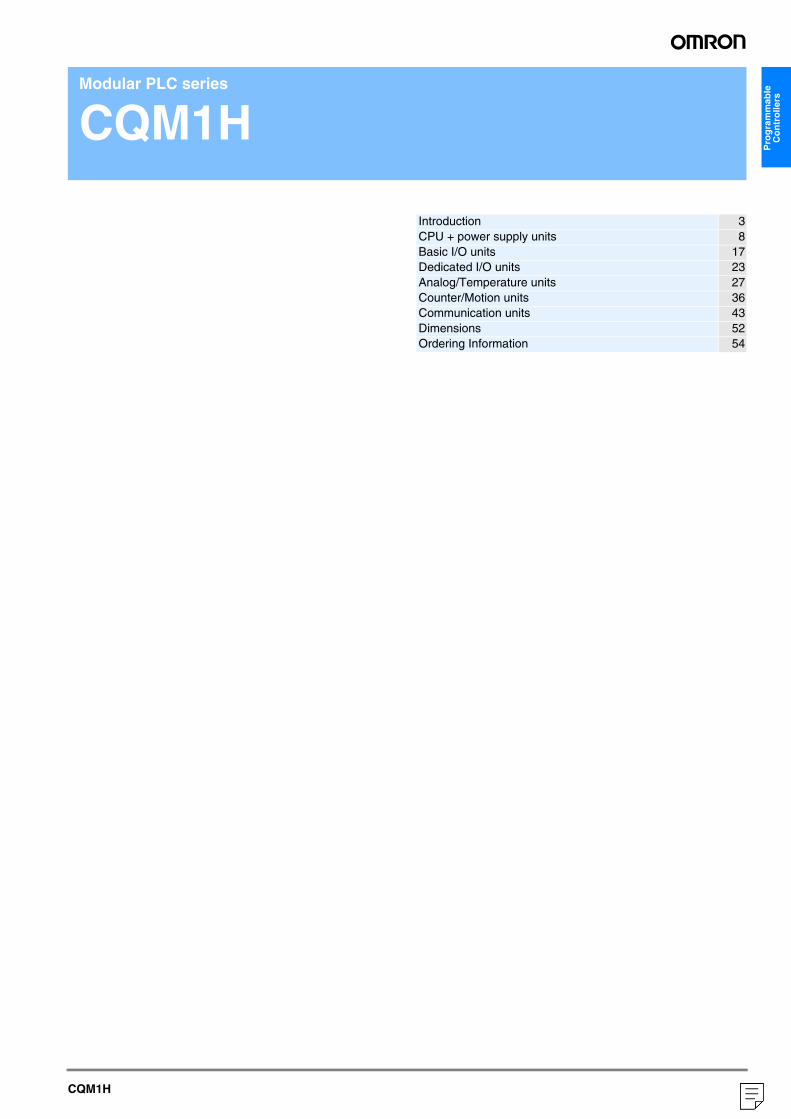
The original modular PLC system for versatile machine control
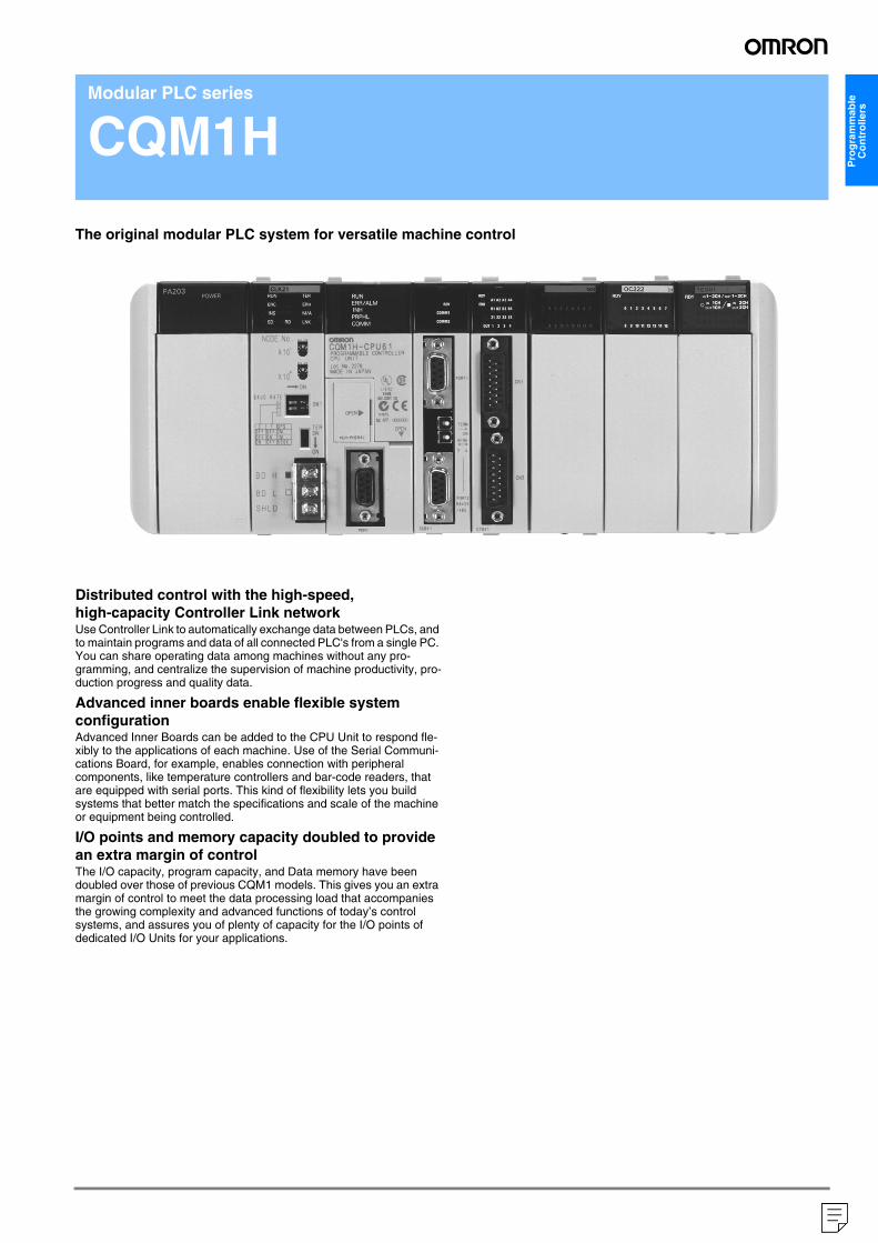
Distributed control with the high-speed, high-capacity Controller Link networkUse Controller Link to automatically exchange data between PLCs, and to maintain programs and data of all connected PLC's from a single PC. You can share operating data among machines without any pro-gramming, and centralize the supervision of machine productivity, pro-duction progress and quality data.
Advanced inner boards enable flexible system configurationAdvanced Inner Boards can be added to the CPU Unit to respond fle-xibly to the applications of each machine. Use of the Serial Communi-cations Board, for example, enables connection with peripheral components, like temperature controllers and bar-code readers, that are equipped with serial ports. This kind of flexibility lets you build systems that better match the specifications and scale of the machine or equipment being controlled.
I/O points and memory capacity doubled to provide an extra margin of controlThe I/O capacity, program capacity, and Data memory have been doubled over those of previous CQM1 models. This gives you an extra margin of control to meet the data processing load that accompanies the growing complexity and advanced functions of today’s control systems, and assures you of plenty of capacity for the I/O points of dedicated I/O Units for your applications.
3
("1:1:20578")
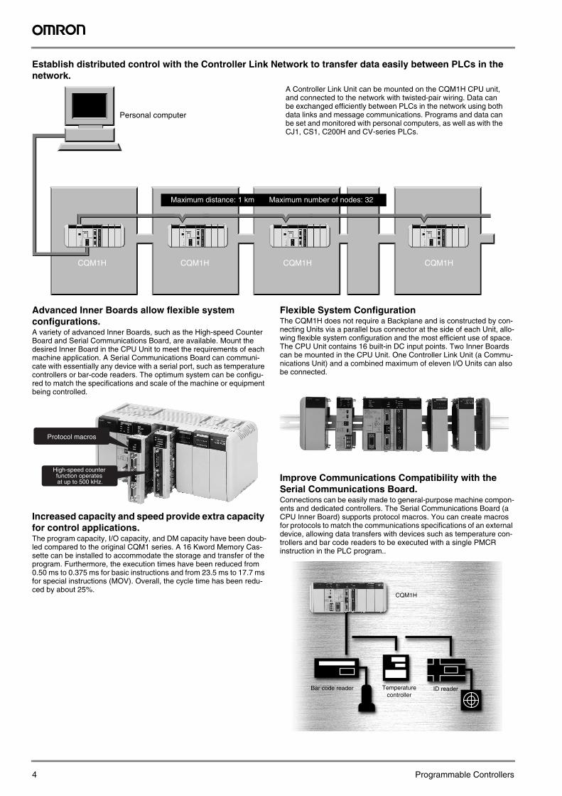
Establish distributed control with the Controller Link Network to transfer data easily between PLCs in the network.
Advanced Inner Boards allow flexible system configurations.A variety of advanced Inner Boards, such as the High-speed Counter Board and Serial Communications Board, are available. Mount the desired Inner Board in the CPU Unit to meet the requirements of each machine application. A Serial Communications Board can communi-cate with essentially any device with a serial port, such as temperature controllers or bar-code readers. The optimum system can be configu-red to match the specifications and scale of the machine or equipment being controlled.
Increased capacity and speed provide extra capacity for control applications.The program capacity, I/O capacity, and DM capacity have been doub-led compared to the original CQM1 series. A 16 Kword Memory Cas-sette can be installed to accommodate the storage and transfer of the program. Furthermore, the execution times have been reduced from 0.50 ms to 0.375 ms for basic instructions and from 23.5 ms to 17.7 ms for special instructions (MOV). Overall, the cycle time has been redu-ced by about 25%.
Flexible System ConfigurationThe CQM1H does not require a Backplane and is constructed by con-necting Units via a parallel bus connector at the side of each Unit, allo-wing flexible system configuration and the most efficient use of space. The CPU Unit contains 16 built-in DC input points. Two Inner Boards can be mounted in the CPU Unit. One Controller Link Unit (a Commu-nications Unit) and a combined maximum of eleven I/O Units can also be connected.
Improve Communications Compatibility with the Serial Communications Board.Connections can be easily made to general-purpose machine compon-ents and dedicated controllers. The Serial Communications Board (a CPU Inner Board) supports protocol macros. You can create macros for protocols to match the communications specifications of an external device, allowing data transfers with devices such as temperature con-trollers and bar code readers to be executed with a single PMCR instruction in the PLC program..
CQM1H CQM1H CQM1H CQM1H
Personal computer
Maximum distance: 1 km Maximum number of nodes: 32
A Controller Link Unit can be mounted on the CQM1H CPU unit, and connected to the network with twisted-pair wiring. Data can be exchanged efficiently between PLCs in the network using both data links and message communications. Programs and data can be set and monitored with personal computers, as well as with the CJ1, CS1, C200H and CV-series PLCs.
Protocol macros
High-speed counter function operates at up to 500 kHz.
CQM1H
Bar code reader Temperaturecontroller
ID reader
4 Programmable Controllers
Pro
gra
mm
able
C
on
tro
llers
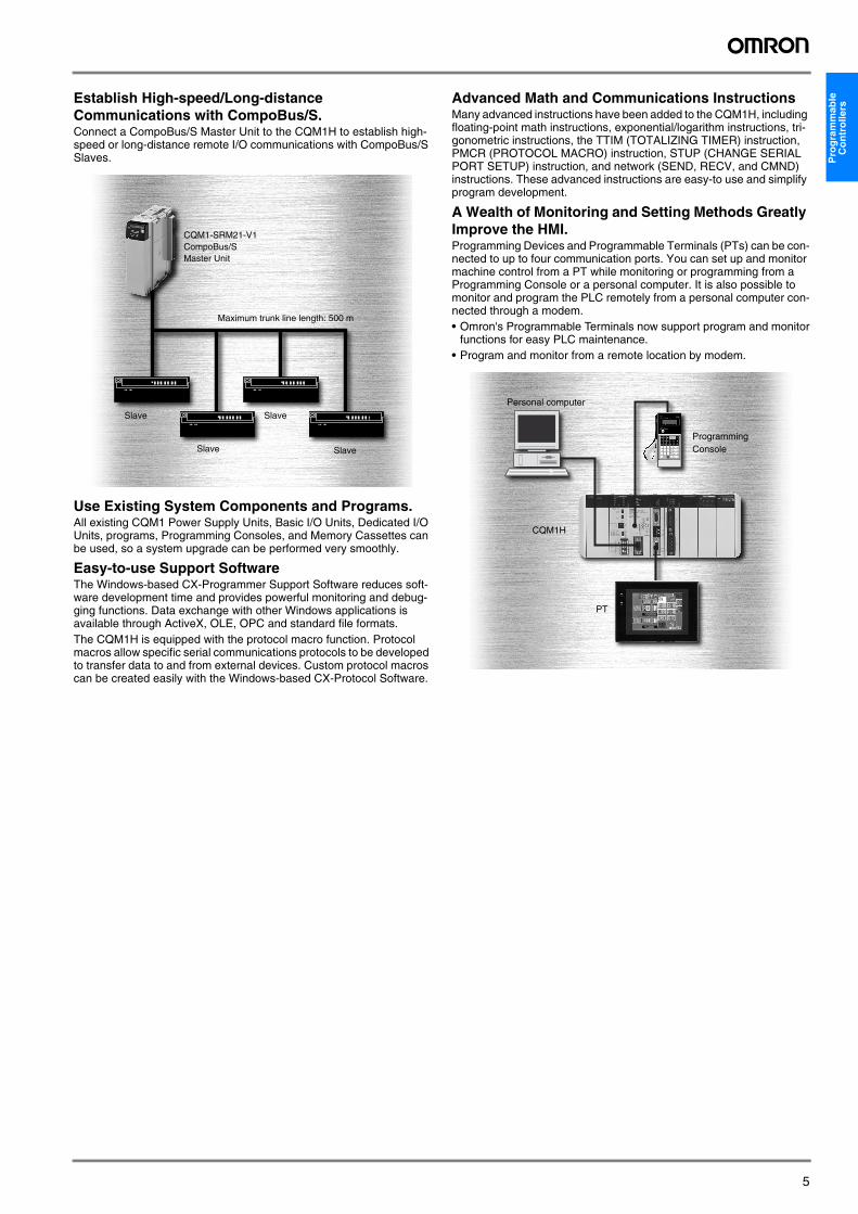
Establish High-speed/Long-distance Communications with CompoBus/S.Connect a CompoBus/S Master Unit to the CQM1H to establish high-speed or long-distance remote I/O communications with CompoBus/S Slaves.
Use Existing System Components and Programs.All existing CQM1 Power Supply Units, Basic I/O Units, Dedicated I/O Units, programs, Programming Consoles, and Memory Cassettes can be used, so a system upgrade can be performed very smoothly.
Easy-to-use Support SoftwareThe Windows-based CX-Programmer Support Software reduces soft-ware development time and provides powerful monitoring and debug-ging functions. Data exchange with other Windows applications is available through ActiveX, OLE, OPC and standard file formats.The CQM1H is equipped with the protocol macro function. Protocol macros allow specific serial communications protocols to be developed to transfer data to and from external devices. Custom protocol macros can be created easily with the Windows-based CX-Protocol Software.
Advanced Math and Communications InstructionsMany advanced instructions have been added to the CQM1H, including floating-point math instructions, exponential/logarithm instructions, tri-gonometric instructions, the TTIM (TOTALIZING TIMER) instruction, PMCR (PROTOCOL MACRO) instruction, STUP (CHANGE SERIAL PORT SETUP) instruction, and network (SEND, RECV, and CMND) instructions. These advanced instructions are easy-to use and simplify program development.
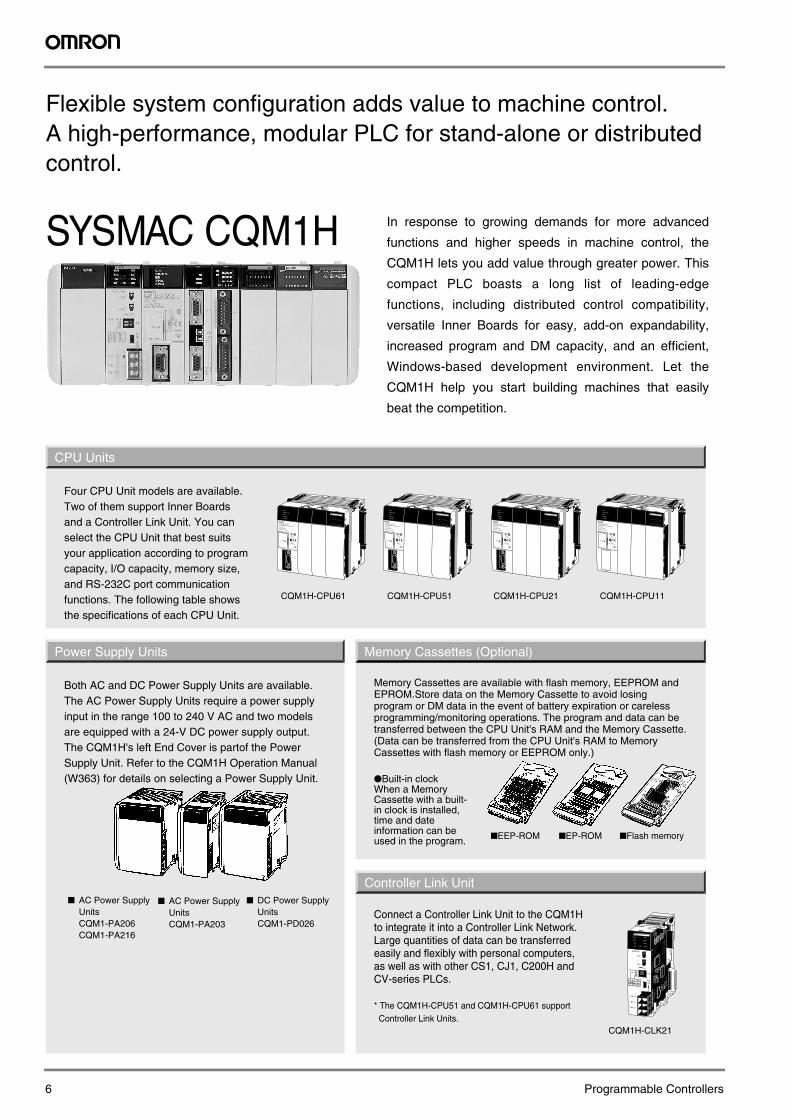
A Wealth of Monitoring and Setting Methods Greatly Improve the HMI.Programming Devices and Programmable Terminals (PTs) can be con-nected to up to four communication ports. You can set up and monitor machine control from a PT while monitoring or programming from a Programming Console or a personal computer. It is also possible to monitor and program the PLC remotely from a personal computer con-nected through a modem.• Omron's Programmable Terminals now support program and monitor
functions for easy PLC maintenance.• Program and monitor from a remote location by modem.
CQM1-SRM21-V1CompoBus/SMaster Unit
Maximum trunk line length: 500 m
Slave
Slave
Slave
Slave
CQM1H
PT
Personal computer
Programming Console
5
CQM1H-CPU61 CQM1H-CPU51 CQM1H-CPU21 CQM1H-CPU11
CQM1H-CLK21
CPU Units
Power Supply Units Memory Cassettes (Optional)
Controller Link Unit
Four CPU Unit models are available. Two of them support Inner Boards and a Controller Link Unit. You can select the CPU Unit that best suits your application according to program capacity, I/O capacity, memory size, and RS-232C port communication functions. The following table shows the specifications of each CPU Unit.
Both AC and DC Power Supply Units are available. The AC Power Supply Units require a power supply input in the range 100 to 240 V AC and two models are equipped with a 24-V DC power supply output. The CQM1H's left End Cover is partof the Power Supply Unit. Refer to the CQM1H Operation Manual (W363) for details on selecting a Power Supply Unit.
Memory Cassettes are available with flash memory, EEPROM and EPROM.Store data on the Memory Cassette to avoid losing program or DM data in the event of battery expiration or careless programming/monitoring operations. The program and data can be transferred between the CPU Unit's RAM and the Memory Cassette. (Data can be transferred from the CPU Unit's RAM to Memory Cassettes with flash memory or EEPROM only.)
●Built-in clockWhen a Memory Cassette with a built-in clock is installed, time and date information can be used in the program.
Connect a Controller Link Unit to the CQM1H to integrate it into a Controller Link Network. Large quantities of data can be transferred easily and flexibly with personal computers, as well as with other CS1, CJ1, C200H and CV-series PLCs.
* The CQM1H-CPU51 and CQM1H-CPU61 support Controller Link Units.
■EEP-ROM ■EP-ROM ■Flash memory
■ AC Power Supply UnitsCQM1-PA206CQM1-PA216
SYSMAC CQM1H
Flexible system configuration adds value to machine control.A high-performance, modular PLC for stand-alone or distributedcontrol.
In response to growing demands for more advanced
functions and higher speeds in machine control, the
CQM1H lets you add value through greater power. This
compact PLC boasts a long list of leading-edge
functions, including distributed control compatibility,
versatile Inner Boards for easy, add-on expandability,
increased program and DM capacity, and an efficient,
Windows-based development environment. Let the
CQM1H help you start building machines that easily
beat the competition.
■ AC Power Supply UnitsCQM1-PA203
■ DC Power Supply UnitsCQM1-PD026
6 Programmable Controllers
Pro
gra
mm
able
C
on
tro
llers
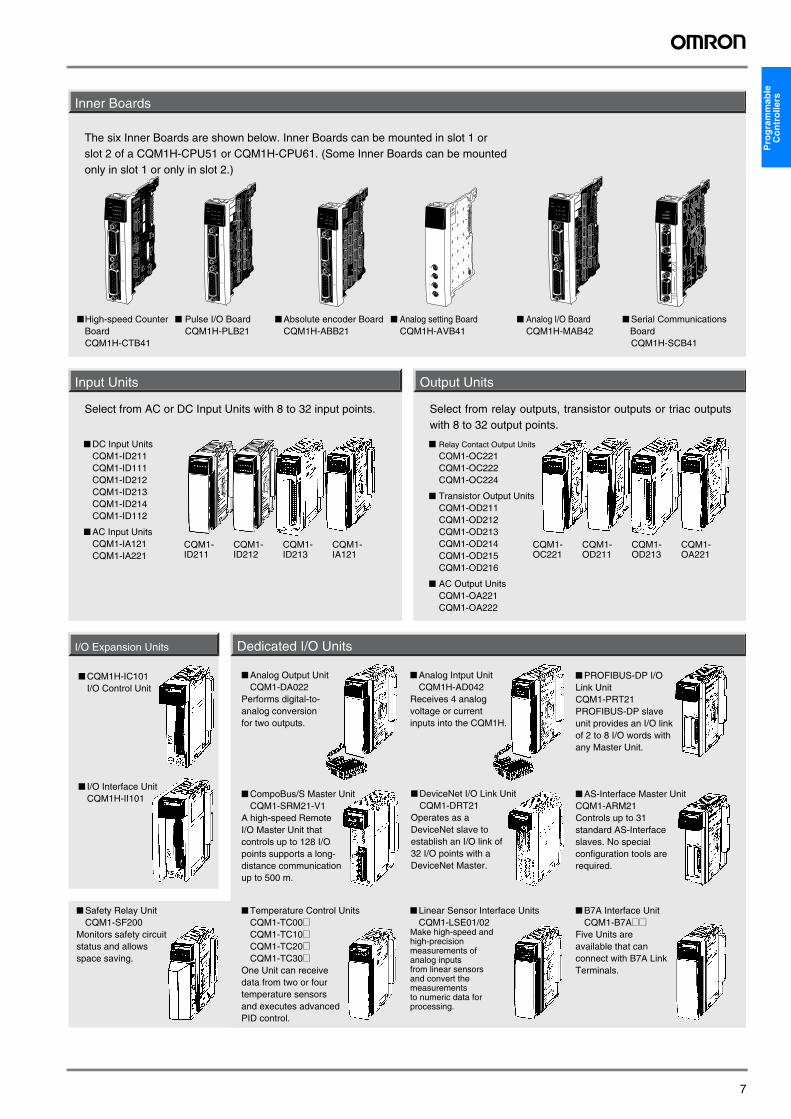
Inner BoardsInput Units Output Units
■High-speed Counter Board
CQM1H-CTB41
■ Pulse I/O BoardCQM1H-PLB21
■ Absolute encoder BoardCQM1H-ABB21
■ Analog setting BoardCQM1H-AVB41
■ Analog I/O BoardCQM1H-MAB42
■ Serial Communications Board
CQM1H-SCB41
The six Inner Boards are shown below. Inner Boards can be mounted in slot 1 or slot 2 of a CQM1H-CPU51 or CQM1H-CPU61. (Some Inner Boards can be mounted only in slot 1 or only in slot 2.)
CQM1-ID211
CQM1-ID212
CQM1-ID213
CQM1-IA121
Select from AC or DC Input Units with 8 to 32 input points.
■ DC Input UnitsCQM1-ID211CQM1-ID111CQM1-ID212CQM1-ID213CQM1-ID214CQM1-ID112
■ AC Input UnitsCQM1-IA121CQM1-IA221
CQM1-OC221
CQM1-OD211
CQM1-OD213
CQM1-OA221
Select from relay outputs, transistor outputs or triac outputs with 8 to 32 output points.
■ Relay Contact Output Units
CQM1-OC221CQM1-OC222CQM1-OC224
■ Transistor Output UnitsCQM1-OD211CQM1-OD212CQM1-OD213CQM1-OD214CQM1-OD215CQM1-OD216
■ AC Output UnitsCQM1-OA221CQM1-OA222
Dedicated I/O UnitsI/O Expansion Units
■ CQM1H-IC101I/O Control Unit
■ I/O Interface UnitCQM1H-II101
■ Analog Output UnitCQM1-DA022
Performs digital-to-analog conversion for two outputs.
■ CompoBus/S Master UnitCQM1-SRM21-V1
A high-speed Remote I/O Master Unit that controls up to 128 I/O points supports a long-distance communication up to 500 m.
■ Temperature Control UnitsCQM1-TC00@CQM1-TC10@CQM1-TC20@CQM1-TC30@
One Unit can receive data from two or four temperature sensors and executes advanced PID control.
■ Analog Intput UnitCQM1H-AD042
Receives 4 analog voltage or current inputs into the CQM1H.
■ DeviceNet I/O Link UnitCQM1-DRT21
Operates as a DeviceNet slave to establish an I/O link of 32 I/O points with a DeviceNet Master.
■ Linear Sensor Interface UnitsCQM1-LSE01/02
Make high-speed and high-precision measurements of analog inputsfrom linear sensors and convert the measurements to numeric data for processing.
■ PROFIBUS-DP I/O Link UnitCQM1-PRT21PROFIBUS-DP slave unit provides an I/O link of 2 to 8 I/O words with any Master Unit.
■ B7A Interface UnitCQM1-B7A@@
Five Units are available that can connect with B7A Link Terminals.
■ Safety Relay UnitCQM1-SF200
Monitors safety circuit status and allows space saving.
■ AS-Interface Master UnitCQM1-ARM21Controls up to 31 standard AS-Interface slaves. No special configuration tools are required.
7
CQM1H CPU Units
CQM1H-CPU@@
CPU UnitsThe four models of CPU Units can be broadly divided into two groups: Models that support Inner Boards and the Controller Link Unit, and models that do not. The CPU Units also vary in their program capacities, I/O capacities, memory capacities, and the presence of an RS-232C port, as shown in the Basic Specifications table, below.
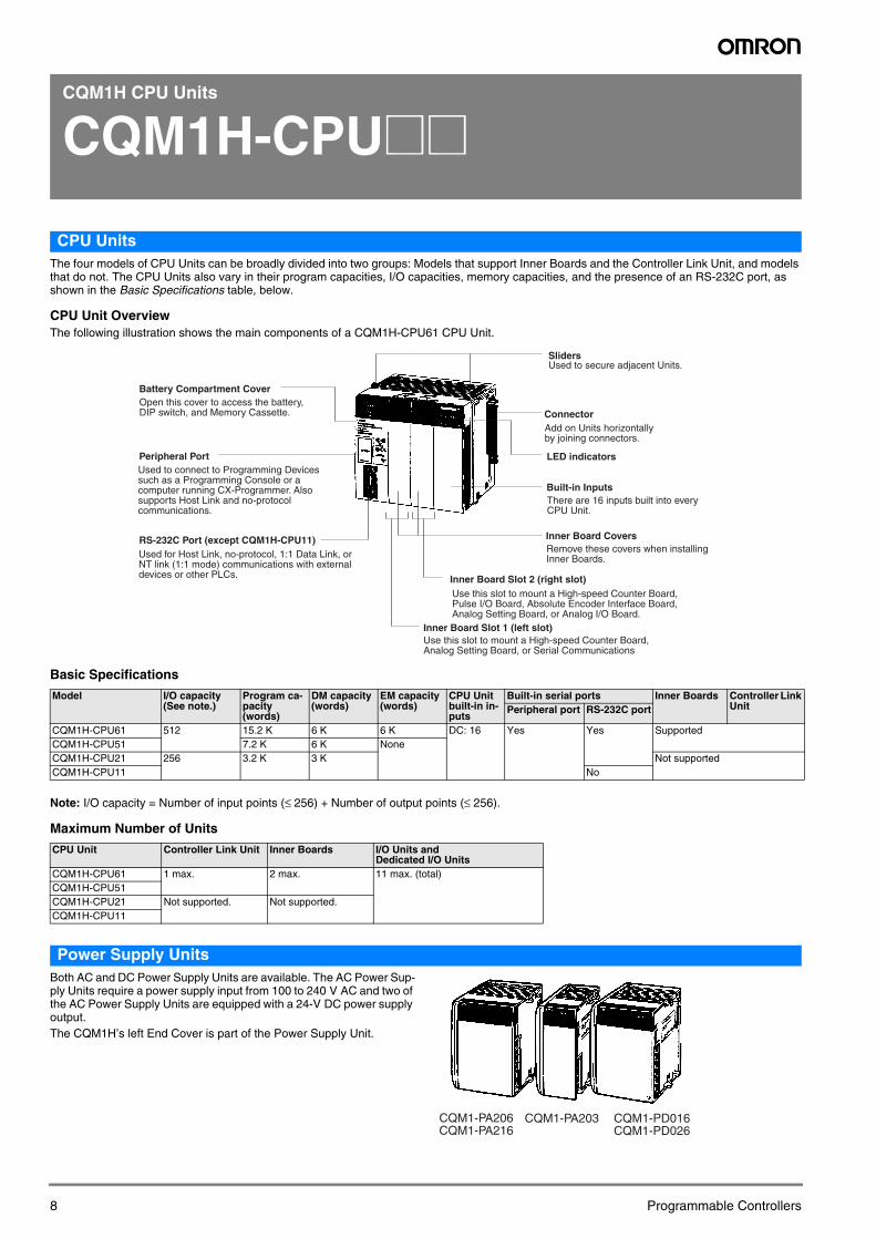
CPU Unit OverviewThe following illustration shows the main components of a CQM1H-CPU61 CPU Unit.
Basic Specifications
Note: I/O capacity = Number of input points (≤ 256) + Number of output points (≤ 256).
Maximum Number of Units
Power Supply UnitsBoth AC and DC Power Supply Units are available. The AC Power Sup-ply Units require a power supply input from 100 to 240 V AC and two of the AC Power Supply Units are equipped with a 24-V DC power supply output.The CQM1H’s left End Cover is part of the Power Supply Unit.
Model I/O capacity (See note.)
Program ca-pacity (words)
DM capacity (words)
EM capacity (words)
CPU Unit built-in in-puts
Built-in serial ports Inner Boards Controller Link UnitPeripheral port RS-232C port
CQM1H-CPU61 512 15.2 K 6 K 6 K DC: 16 Yes Yes SupportedCQM1H-CPU51 7.2 K 6 K NoneCQM1H-CPU21 256 3.2 K 3 K Not supportedCQM1H-CPU11 No
CPU Unit Controller Link Unit Inner Boards I/O Units and Dedicated I/O Units
CQM1H-CPU61 1 max. 2 max. 11 max. (total)CQM1H-CPU51CQM1H-CPU21 Not supported. Not supported.CQM1H-CPU11
Peripheral Port
RS-232C Port (except CQM1H-CPU11)
LED indicators
Inner Board Slot 1 (left slot)
Inner Board Slot 2 (right slot)
Battery Compartment Cover
Inner Board Covers
Built-in Inputs
Connector
SlidersUsed to secure adjacent Units.
Open this cover to access the battery, DIP switch, and Memory Cassette.
Used to connect to Programming Devices such as a Programming Console or a computer running CX-Programmer. Also supports Host Link and no-protocol communications.
Used for Host Link, no-protocol, 1:1 Data Link, or NT link (1:1 mode) communications with external devices or other PLCs.
Use this slot to mount a High-speed Counter Board, Analog Setting Board, or Serial Communications
Use this slot to mount a High-speed Counter Board, Pulse I/O Board, Absolute Encoder Interface Board, Analog Setting Board, or Analog I/O Board.
Remove these covers when installing Inner Boards.
There are 16 inputs built into every CPU Unit.
Add on Units horizontally by joining connectors.
CQM1-PA203 CQM1-PD016CQM1-PD026
CQM1-PA206CQM1-PA216
8 Programmable Controllers
Pro
gra
mm
able
C
on
tro
llers
Specifications
Note: The total power consumed at 5 V DC and 24 V DC must be less than 30 W.(5 × Current consumed at 5 V DC) + (24 × Current consumed at 24 V DC) ≤ 30 W
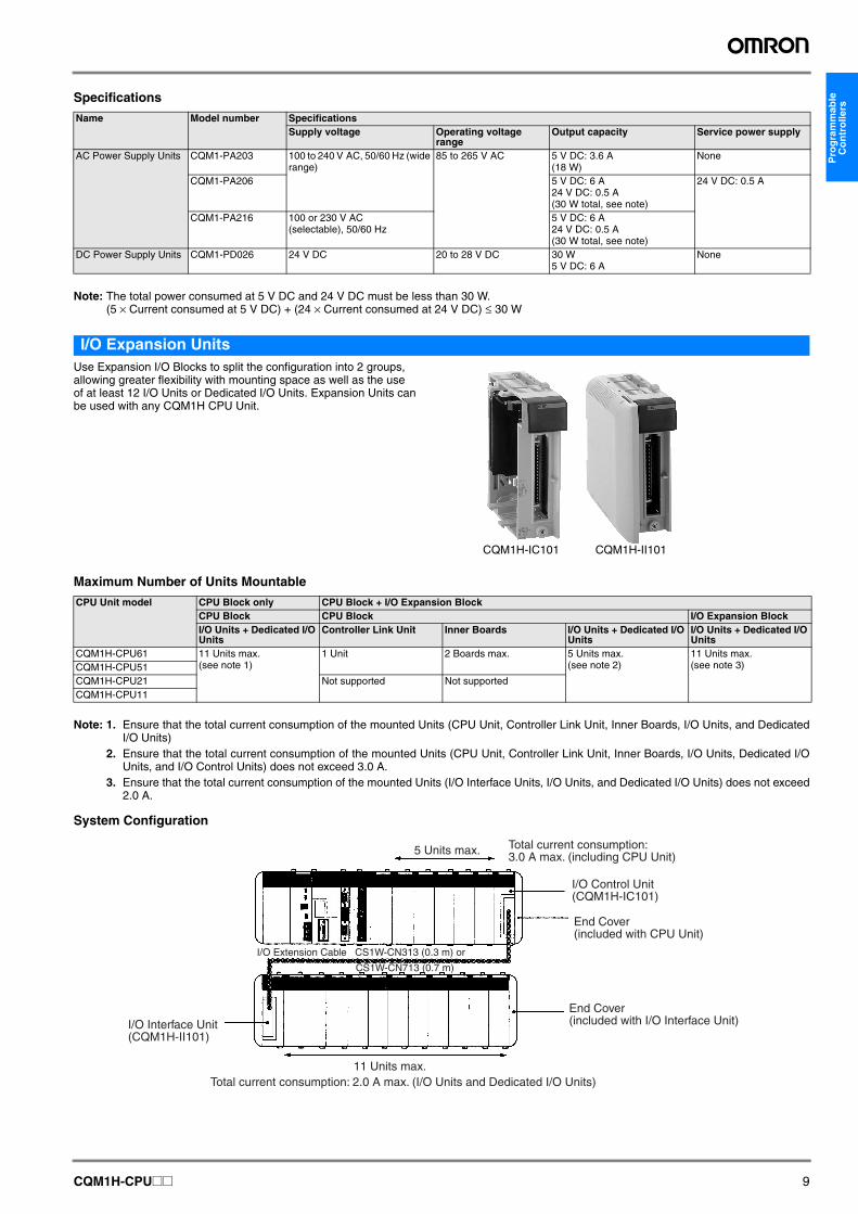
I/O Expansion UnitsUse Expansion I/O Blocks to split the configuration into 2 groups, allowing greater flexibility with mounting space as well as the use of at least 12 I/O Units or Dedicated I/O Units. Expansion Units can be used with any CQM1H CPU Unit.
Maximum Number of Units Mountable
Note: 1. Ensure that the total current consumption of the mounted Units (CPU Unit, Controller Link Unit, Inner Boards, I/O Units, and DedicatedI/O Units)
2. Ensure that the total current consumption of the mounted Units (CPU Unit, Controller Link Unit, Inner Boards, I/O Units, Dedicated I/OUnits, and I/O Control Units) does not exceed 3.0 A.
3. Ensure that the total current consumption of the mounted Units (I/O Interface Units, I/O Units, and Dedicated I/O Units) does not exceed2.0 A.
System Configuration
Name Model number SpecificationsSupply voltage Operating voltage
rangeOutput capacity Service power supply
AC Power Supply Units CQM1-PA203 100 to 240 V AC, 50/60 Hz (wide range)
85 to 265 V AC 5 V DC: 3.6 A(18 W)
None
CQM1-PA206 5 V DC: 6 A24 V DC: 0.5 A(30 W total, see note)
24 V DC: 0.5 A
CQM1-PA216 100 or 230 V AC (selectable), 50/60 Hz
5 V DC: 6 A24 V DC: 0.5 A(30 W total, see note)
DC Power Supply Units CQM1-PD026 24 V DC 20 to 28 V DC 30 W5 V DC: 6 A
None
CQM1H-IC101 CQM1H-II101
CPU Unit model CPU Block only CPU Block + I/O Expansion BlockCPU Block CPU Block I/O Expansion BlockI/O Units + Dedicated I/O Units
Controller Link Unit Inner Boards I/O Units + Dedicated I/O Units
I/O Units + Dedicated I/O Units
CQM1H-CPU61 11 Units max. (see note 1)
1 Unit 2 Boards max. 5 Units max. (see note 2)
11 Units max. (see note 3)CQM1H-CPU51
CQM1H-CPU21 Not supported Not supportedCQM1H-CPU11
5 Units max.
11 Units max.Total current consumption: 2.0 A max. (I/O Units and Dedicated I/O Units)
I/O Extension Cable CS1W-CN313 (0.3 m) or
CS1W-CN713 (0.7 m)
Total current consumption:3.0 A max. (including CPU Unit)
I/O Control Unit (CQM1H-IC101)
End Cover (included with CPU Unit)
End Cover (included with I/O Interface Unit)I/O Interface Unit
(CQM1H-II101)
CQM1H-CPU@@ 9
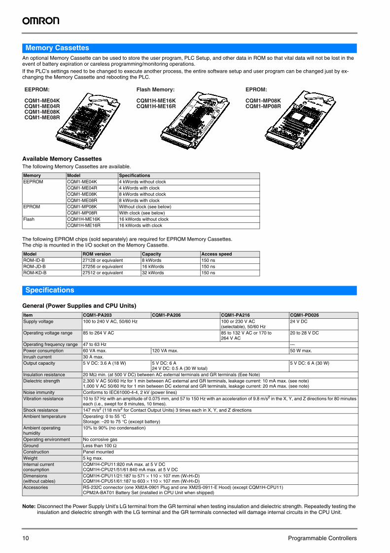
Memory CassettesAn optional Memory Cassette can be used to store the user program, PLC Setup, and other data in ROM so that vital data will not be lost in the event of battery expiration or careless programming/monitoring operations. If the PLC’s settings need to be changed to execute another process, the entire software setup and user program can be changed just by ex-changing the Memory Cassette and rebooting the PLC.
Available Memory CassettesThe following Memory Cassettes are available.
The following EPROM chips (sold separately) are required for EPROM Memory Cassettes. The chip is mounted in the I/O socket on the Memory Cassette.
Specifications
General (Power Supplies and CPU Units)
Note: Disconnect the Power Supply Unit's LG terminal from the GR terminal when testing insulation and dielectric strength. Repeatedly testing the insulation and dielectric strength with the LG terminal and the GR terminals connected will damage internal circuits in the CPU Unit.
Memory Model SpecificationsEEPROM CQM1-ME04K 4 kWords without clock
CQM1-ME04R 4 kWords with clockCQM1-ME08K 8 kWords without clockCQM1-ME08R 8 kWords with clock
EPROM CQM1-MP08K Without clock (see below)CQM1-MP08R With clock (see below)
Flash CQM1H-ME16K 16 kWords without clockCQM1H-ME16R 16 kWords with clock
Model ROM version Capacity Access speedROM-ID-B 27128 or equivalent 8 kWords 150 nsROM-JD-B 27256 or equivalent 16 kWords 150 nsROM-KD-B 27512 or equivalent 32 kWords 150 ns
Item CQM1-PA203 CQM1-PA206 CQM1-PA216 CQM1-PD026Supply voltage 100 to 240 V AC, 50/60 Hz 100 or 230 V AC
(selectable), 50/60 Hz24 V DC
Operating voltage range 85 to 264 V AC 85 to 132 V AC or 170 to 264 V AC
20 to 28 V DC
Operating frequency range 47 to 63 Hz ---Power consumption 60 VA max. 120 VA max. 50 W max.Inrush current 30 A max.Output capacity 5 V DC: 3.6 A (18 W) 5 V DC: 6 A
24 V DC: 0.5 A (30 W total)5 V DC: 6 A (30 W)
Insulation resistance 20 MΩ min. (at 500 V DC) between AC external terminals and GR terminals (Eee Note)Dielectric strength 2,300 V AC 50/60 Hz for 1 min between AC external and GR terminals, leakage current: 10 mA max. (see note)
1,000 V AC 50/60 Hz for 1 min between DC external and GR terminals, leakage current: 20 mA max. (see note)Noise immunity Conforms to IEC61000-4-4, 2 kV (power lines)Vibration resistance 10 to 57 Hz with an amplitude of 0.075 mm, and 57 to 150 Hz with an acceleration of 9.8 m/s2 in the X, Y, and Z directions for 80 minutes
each (i.e., swept for 8 minutes, 10 times).Shock resistance 147 m/s2 (118 m/s2 for Contact Output Units) 3 times each in X, Y, and Z directions Ambient temperature Operating: 0 to 55 °C
Storage: –20 to 75 °C (except battery)Ambient operating humidity
10% to 90% (no condensation)
Operating environment No corrosive gasGround Less than 100 ΩConstruction Panel mountedWeight 5 kg max.Internal current consumption
CQM1H-CPU11:820 mA max. at 5 V DCCQM1H-CPU21/51/61:840 mA max. at 5 V DC
Dimensions (without cables)
CQM1H-CPU11/21:187 to 571 × 110 × 107 mm (W×H×D)CQM1H-CPU51/61:187 to 603 × 110 × 107 mm (W×H×D)
Accessories RS-232C connector (one XM2A-0901 Plug and one XM2S-0911-E Hood) (except CQM1H-CPU11)CPM2A-BAT01 Battery Set (installed in CPU Unit when shipped)
EEPROM:
CQM1-ME04KCQM1-ME04RCQM1-ME08KCQM1-ME08R
Flash Memory:
CQM1H-ME16KCQM1H-ME16R
EPROM:
CQM1-MP08KCQM1-MP08R
10 Programmable Controllers
Pro
gra
mm
able
C
on
tro
llers
CPU Unit
Characteristics
Note: Analog Power Supply Units must also be counted.
Item SpecificationsControl method Stored program methodI/O control method Cyclic scan and direct output/immediate interrupt processingProgramming language Ladder-diagram programmingI/O capacity CQM1H-CPU11/21:256
CQM1H-CPU51/61:512Program capacity CQM1H-CPU11/21: 3.2 kWords
CQM1H-CPU51: 7.2 kWordsCQM1H-CPU61: 15.2 kWords
Data memory capacity CQM1H-CPU11/21: 3 kWordsCQM1H-CPU51: 6 kWordsCQM1H-CPU61: 12 kWords (DM: 6 kWords; EM: 6 kWords)
Instruction length 1 step per instruction, 1 to 4 words per instructionNumber of instructions 162 (14 basic, 148 special instructions)Instruction execution times Basic instructions: 0.375 to 1.125 μs
Special instructions:17.7 μs (MOV instruction)Overseeing time 0.70 msMounting structure No Backplane (Units are joined horizontally using connectors)Mounting DIN rail mounting (screw mounting not possible)CPU Unit built-in DC input points 16Maximum number of Units CPU Block only: 11 Units (I/O Units and Dedicated I/O Units) max.
CPU Block and Expansion I/O BlockCPU Block: 5 Units max.Expansion I/O Block: 11 Units max.
Inner Boards CQM1H-CPU11/21:NoneCQM1H-CPU51/61:2 Boards
Communications Units (Controller Link Unit)
CQM1H-CPU11/21:NoneCQM1H-CPU51/61:1 Unit
Types of interrupts
Input interrupts(4 inputs max.)
Input Interrupt Mode: Interrupts are executed in response to inputs from external sources to the CPU Unit’s built-in input points.Counter Mode: Interrupts are executed in response to reception of a set number of pulses (counted down) via the CPU Unit’s internal built-in input points (4 points).
Interval timer interrupts(3 timers max.)
Scheduled Interrupt Mode: Program is interrupted at regular intervals measured by one of the CPU Unit’s internal timers.One-shot Interrupt Mode: An interrupt is executed after a set time, measured by one of the CPU Unit’s internal timers.
High-speed counter inter-rupts
Target Value Comparison: Interrupt is executed when the high-speed counter PV is equal to a specified value.Range Comparison: Interrupt is executed when the high-speed counter PV lies within a specified range.Note: Counting is possible for high-speed counter inputs from the CPU Unit’s internal input points, Pulse
I/O Boards, or Absolute Encoder Interface Boards. (The High-speed Counter Board has no interrupt function, but can output bit patterns internally and externally.)
I/O allocations I/O is automatically allocated in order from the Unit nearest to the CPU Unit. (Because there are no I/O tables, it is not necessary, and not possible, to create I/O tables from a Programming Device.)
CQM1H-CPU@@ 11
Memory Area Structure
Memory Cassette Specifications
Data area Size Words Bits FunctionIR area Input area 256 bits IR 000 to IR 015 IR 00000 to
IR 01515Input bits are allocated to Input Units or Dedicated I/O Units. The 16 bits in IR 000 are always allocated to the CPU Unit’s built-in inputs. Bits in IR 001 to IR 015 are allocated to I/O or Dedicated I/O Units connected to the CPU Unit.
Output area
256 bits IR 100 to IR 115 IR 10000 to IR 11515
Output bits are allocated to Output Units or Dedicated I/O Units connected to the CPU Unit.
Work areas
2,528 bits min. IR 016 to IR 089 IR 01600 to IR 08915
Work bits do not have any specific function and they can be freely used within the program.(A minimum 2,528 bits are available as work bits. Most bits in the IR and LR areas can be used as work bits when they are not used for their allocated functions, so the total number of available work bits depends on the configuration of the PLC.)
IR 116 to IR 189 IR 11600 to IR 18915
IR 216 to IR 219 IR 21600 to IR 21915
IR 224 to IR 229 IR 22400 to IR 22915
Controller Link status ar-eas
96 bits IR 090 to IR 095 IR 09000 to IR 09515
Status Area 1: Stores the Controller Link data link status information.
96 bits IR 190 to IR 195 IR 19000 to IR 19515
Status Area 2: Stores the Controller Link error and network participation informa-tion.
MACRO op-erand area
Input area 64 bits IR 096 to IR 099 IR 09600 to IR 09915
Used when the MACRO instruction, MCRO(99), is used.
Output area
64 bits IR 196 to IR 199 IR 19600 to IR 19915
Inner Board slot 1 area 256 bits IR 200 to IR 215 IR 20000 to IR 21515
These bits are allocated to the Inner Board mounted in slot 1 of a CQM1H-CPU51/61.High-speed Counter Board:IR 200 to IR 213Serial Communications Board:IR 200 to IR 207
Analog settings area 64 bits IR 220 to IR 223 IR 22000 to IR 22315
Used to store the analog settings when a CQM1H-AVB41 Analog Setting Board is mounted.
High-speed Counter 0 PV 32 bits IR 230 to IR 231 IR 23000 to IR 23115
Used to store the present values of high-speed counter 0.
Inner Board slot 2 area 192 bits IR 232 to IR 243 IR 23200 to IR 24315
These bits are allocated to the Inner Board mounted in slot 2.High-speed Counter Board:IR 232 to IR 243Absolute Encoder Interface Board:IR 232 to IR 239Pulse I/O Board: IR 232 to IR 239Analog I/O Board:IR 232 to IR 239
SR area 184 bits SR 244 to SR 255 SR 24400 to SR 25507
These bits serve specific functions such as flags and control bits.
HR area 1,600 bits HR 00 to HR 99 HR 0000 to HR 9915
These bits store data and retain their ON/OFF status when power is turned OFF or when the operating mode is changed.
AR area 448 bits AR 00 to AR 27 AR 0000 to AR 2715
These bits serve specific functions such as flags and control bits.
TR area 8 bits --- TR 0 to TR 7 These bits are used to temporarily store ON/OFF status at program branches.LR area 1,024 bits LR 00 to LR 63 LR 0000 to LR 6315 Used for 1:1 data link through the RS-232 port or through a Controller Link Unit.Timer/Counter area 512 bits TIM/CNT 000 to TIM/CNT 511
(timer/counter numbers)The same numbers are used for both timers and counters.Timer numbers 000 to 015 can be used with TIMH(15) for interrupt-refreshed PVs to ensure proper timing without inaccuracy being caused by the cycle time.
DM area Read/write 3,072 words DM 0000 to DM 3071
--- DM area data can be accessed in word units only. Word values are retained when the power is turned OFF.
3,072 words DM 3072 to DM 6143
--- Available in CQM1H-CPU51/61 CPU Units only.
Read-only4 425 words DM 6144 to DM 6568
--- Cannot be written from the program (only from a Programming Device).DM 6400 to DM 6409:Controller Link parametersDM 6450 to DM 6499: Routing tablesDM 6550 to DM 6559: Serial Communications Board Setup
Error history area4
31 words DM 6569 to DM 6599
--- Cannot be written from the program (only from a Programming Device). Stores the time of occurrence and error code of errors that occur.
PLC Setup4
56 words DM 6600 to DM 6655
--- Cannot be written from the program (only from a Programming Device). Stores various parameters that control PLC operation.
EM area 6,144 words EM 0000 to EM 6143
--- EM area data can be accessed in word units only. Word values are retained when the power is turned OFF or the operating mode is changed. (CQM1H-CPU61 CPU Unit only.)
Item DetailsMemory Cassette (EEPROM or flash memory)
Mounted from the front of the CPU Unit and used to store and read the user’s program, DM (read-only DM and PLC Setup), and expan-sion instruction information as one block. It is possible to set the CPU Unit so that data stored in the Memory Cassette (user’s program, DM, expansion instruction information) is automatically sent to the CPU Unit (auto-boot) at startup. Transfer and comparison of data be-tween the CPU Unit and Memory Cassette are possible using AR area control bits.
12 Programmable Controllers
Pro
gra
mm
able
C
on
tro
llers
Other Functions
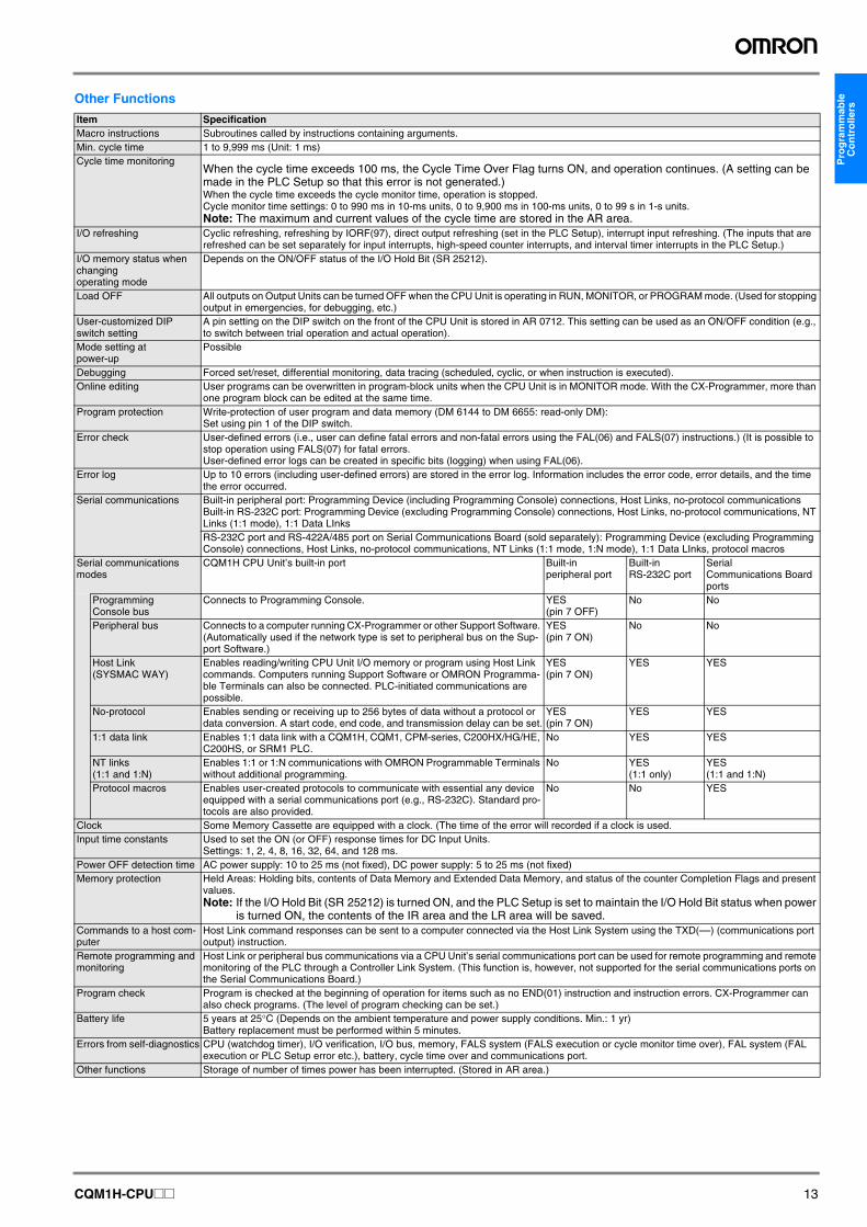
Item SpecificationMacro instructions Subroutines called by instructions containing arguments.Min. cycle time 1 to 9,999 ms (Unit: 1 ms)Cycle time monitoring
When the cycle time exceeds 100 ms, the Cycle Time Over Flag turns ON, and operation continues. (A setting can be made in the PLC Setup so that this error is not generated.)When the cycle time exceeds the cycle monitor time, operation is stopped.Cycle monitor time settings: 0 to 990 ms in 10-ms units, 0 to 9,900 ms in 100-ms units, 0 to 99 s in 1-s units. Note: The maximum and current values of the cycle time are stored in the AR area.
I/O refreshing Cyclic refreshing, refreshing by IORF(97), direct output refreshing (set in the PLC Setup), interrupt input refreshing. (The inputs that are refreshed can be set separately for input interrupts, high-speed counter interrupts, and interval timer interrupts in the PLC Setup.)
I/O memory status when changing operating mode
Depends on the ON/OFF status of the I/O Hold Bit (SR 25212).
Load OFF All outputs on Output Units can be turned OFF when the CPU Unit is operating in RUN, MONITOR, or PROGRAM mode. (Used for stopping output in emergencies, for debugging, etc.)
User-customized DIP switch setting
A pin setting on the DIP switch on the front of the CPU Unit is stored in AR 0712. This setting can be used as an ON/OFF condition (e.g., to switch between trial operation and actual operation).
Mode setting at power-up
Possible
Debugging Forced set/reset, differential monitoring, data tracing (scheduled, cyclic, or when instruction is executed).Online editing User programs can be overwritten in program-block units when the CPU Unit is in MONITOR mode. With the CX-Programmer, more than
one program block can be edited at the same time.Program protection Write-protection of user program and data memory (DM 6144 to DM 6655: read-only DM):
Set using pin 1 of the DIP switch.Error check User-defined errors (i.e., user can define fatal errors and non-fatal errors using the FAL(06) and FALS(07) instructions.) (It is possible to
stop operation using FALS(07) for fatal errors.User-defined error logs can be created in specific bits (logging) when using FAL(06).
Error log Up to 10 errors (including user-defined errors) are stored in the error log. Information includes the error code, error details, and the time the error occurred.
Serial communications Built-in peripheral port: Programming Device (including Programming Console) connections, Host Links, no-protocol communicationsBuilt-in RS-232C port: Programming Device (excluding Programming Console) connections, Host Links, no-protocol communications, NT Links (1:1 mode), 1:1 Data LInksRS-232C port and RS-422A/485 port on Serial Communications Board (sold separately): Programming Device (excluding Programming Console) connections, Host Links, no-protocol communications, NT Links (1:1 mode, 1:N mode), 1:1 Data LInks, protocol macros
Serial communications modes
CQM1H CPU Unit’s built-in port Built-in peripheral port
Built-in RS-232C port
Serial Communications Board ports
Programming Console bus
Connects to Programming Console. YES (pin 7 OFF)
No No
Peripheral bus Connects to a computer running CX-Programmer or other Support Software. (Automatically used if the network type is set to peripheral bus on the Sup-port Software.)
YES (pin 7 ON)
No No
Host Link (SYSMAC WAY)
Enables reading/writing CPU Unit I/O memory or program using Host Link commands. Computers running Support Software or OMRON Programma-ble Terminals can also be connected. PLC-initiated communications are possible.
YES (pin 7 ON)
YES YES
No-protocol Enables sending or receiving up to 256 bytes of data without a protocol or data conversion. A start code, end code, and transmission delay can be set.
YES(pin 7 ON)
YES YES
1:1 data link Enables 1:1 data link with a CQM1H, CQM1, CPM-series, C200HX/HG/HE, C200HS, or SRM1 PLC.
No YES YES
NT links (1:1 and 1:N)
Enables 1:1 or 1:N communications with OMRON Programmable Terminals without additional programming.
No YES (1:1 only)
YES (1:1 and 1:N)
Protocol macros Enables user-created protocols to communicate with essential any device equipped with a serial communications port (e.g., RS-232C). Standard pro-tocols are also provided.
No No YES
Clock Some Memory Cassette are equipped with a clock. (The time of the error will recorded if a clock is used.Input time constants Used to set the ON (or OFF) response times for DC Input Units.
Settings: 1, 2, 4, 8, 16, 32, 64, and 128 ms.Power OFF detection time AC power supply: 10 to 25 ms (not fixed), DC power supply: 5 to 25 ms (not fixed)Memory protection Held Areas: Holding bits, contents of Data Memory and Extended Data Memory, and status of the counter Completion Flags and present
values.Note: If the I/O Hold Bit (SR 25212) is turned ON, and the PLC Setup is set to maintain the I/O Hold Bit status when power
is turned ON, the contents of the IR area and the LR area will be saved.Commands to a host com-puter
Host Link command responses can be sent to a computer connected via the Host Link System using the TXD(––) (communications port output) instruction.
Remote programming and monitoring
Host Link or peripheral bus communications via a CPU Unit’s serial communications port can be used for remote programming and remote monitoring of the PLC through a Controller Link System. (This function is, however, not supported for the serial communications ports on the Serial Communications Board.)
Program check Program is checked at the beginning of operation for items such as no END(01) instruction and instruction errors. CX-Programmer can also check programs. (The level of program checking can be set.)
Battery life 5 years at 25°C (Depends on the ambient temperature and power supply conditions. Min.: 1 yr)Battery replacement must be performed within 5 minutes.
Errors from self-diagnostics CPU (watchdog timer), I/O verification, I/O bus, memory, FALS system (FALS execution or cycle monitor time over), FAL system (FAL execution or PLC Setup error etc.), battery, cycle time over and communications port.
Other functions Storage of number of times power has been interrupted. (Stored in AR area.)
CQM1H-CPU@@ 13
I/O Functions
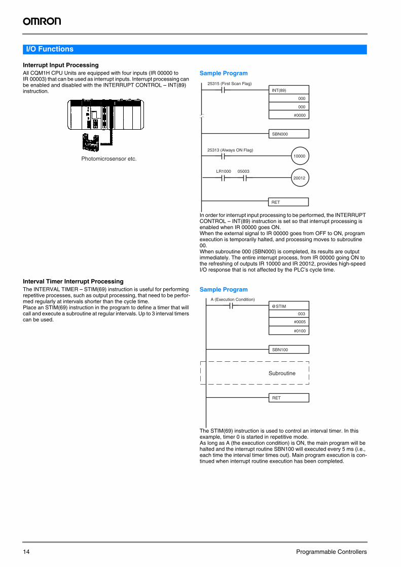
Interrupt Input ProcessingAll CQM1H CPU Units are equipped with four inputs (IR 00000 to IR 00003) that can be used as interrupt inputs. Interrupt processing can be enabled and disabled with the INTERRUPT CONTROL – INT(89) instruction.
Sample Program
In order for interrupt input processing to be performed, the INTERRUPT CONTROL – INT(89) instruction is set so that interrupt processing is enabled when IR 00000 goes ON.When the external signal to IR 00000 goes from OFF to ON, program execution is temporarily halted, and processing moves to subroutine 00.When subroutine 000 (SBN000) is completed, its results are output immediately. The entire interrupt process, from IR 00000 going ON to the refreshing of outputs IR 10000 and IR 20012, provides high-speed I/O response that is not affected by the PLC’s cycle time.
Interval Timer Interrupt ProcessingThe INTERVAL TIMER – STIM(69) instruction is useful for performing repetitive processes, such as output processing, that need to be perfor-med regularly at intervals shorter than the cycle time.Place an STIM(69) instruction in the program to define a timer that will call and execute a subroutine at regular intervals. Up to 3 interval timers can be used.
Sample Program
The STIM(69) instruction is used to control an interval timer. In this example, timer 0 is started in repetitive mode.As long as A (the execution condition) is ON, the main program will be halted and the interrupt routine SBN100 will executed every 5 ms (i.e., each time the interval timer times out). Main program execution is con-tinued when interrupt routine execution has been completed.
Photomicrosensor etc.
INT(89)
000
000
#0000
SBN000
10000
20012
RET
LR1000 05003
25315 (First Scan Flag)
25313 (Always ON Flag)
@STIM
003
#0005
#0100
SBN100
RET
A (Execution Condition)
Subroutine
14 Programmable Controllers
Pro
gra
mm
able
C
on
tro
llers
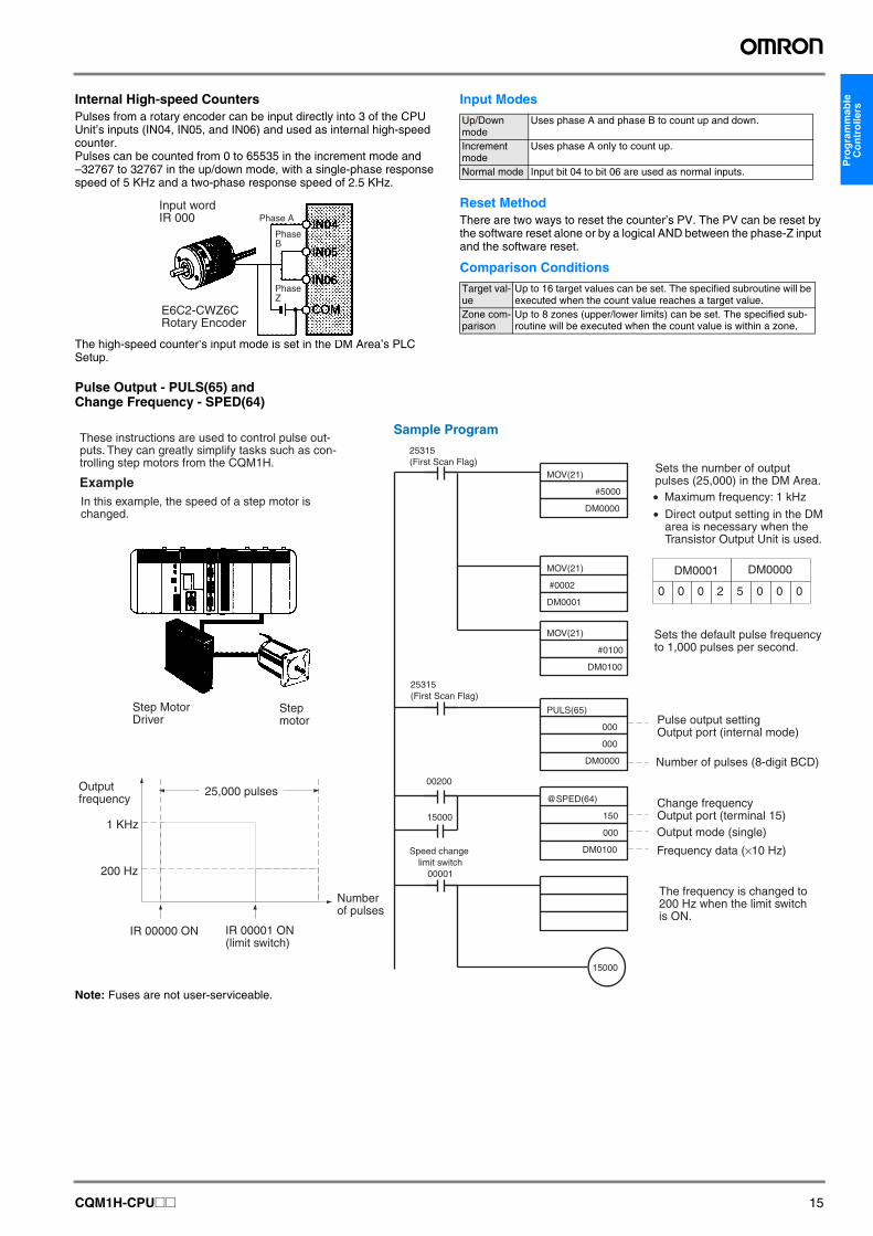
Internal High-speed CountersPulses from a rotary encoder can be input directly into 3 of the CPU Unit’s inputs (IN04, IN05, and IN06) and used as internal high-speed counter.Pulses can be counted from 0 to 65535 in the increment mode and –32767 to 32767 in the up/down mode, with a single-phase response speed of 5 KHz and a two-phase response speed of 2.5 KHz.
The high-speed counter’s input mode is set in the DM Area’s PLC Setup.
Input Modes
Reset MethodThere are two ways to reset the counter’s PV. The PV can be reset by the software reset alone or by a logical AND between the phase-Z input and the software reset.
Comparison Conditions
Pulse Output - PULS(65) and Change Frequency - SPED(64)
Note: Fuses are not user-serviceable.
Phase AInput word IR 000
E6C2-CWZ6CRotary Encoder
Phase B
Phase Z
Up/Down mode
Uses phase A and phase B to count up and down.
Increment mode
Uses phase A only to count up.
Normal mode Input bit 04 to bit 06 are used as normal inputs.
Target val-ue
Up to 16 target values can be set. The specified subroutine will be executed when the count value reaches a target value.
Zone com-parison
Up to 8 zones (upper/lower limits) can be set. The specified sub-routine will be executed when the count value is within a zone.
15000
15000
0 0 0 2 5 0 0 0
DM0001 DM0000
00200
Example
1 KHz
200 Hz
IR 00000 ON
@SPED(64)
150
000
DM0100
PULS(65)
000
000
DM0000
MOV(21)
#5000
DM0000• Maximum frequency: 1 kHz
Number of pulses (8-digit BCD)
Output mode (single)
Frequency data (×10 Hz)
MOV(21)
#0002
DM0001
MOV(21)
#0100
DM0100
Sample ProgramThese instructions are used to control pulse out-puts. They can greatly simplify tasks such as con-trolling step motors from the CQM1H.
In this example, the speed of a step motor is changed.
Step Motor Driver
Step motor
Output frequency
IR 00001 ON (limit switch)
Number of pulses
Sets the number of output pulses (25,000) in the DM Area.
• Direct output setting in the DM area is necessary when the Transistor Output Unit is used.
Sets the default pulse frequency to 1,000 pulses per second.
Pulse output settingOutput port (internal mode)
Change frequencyOutput port (terminal 15)
The frequency is changed to 200 Hz when the limit switch is ON.
25315(First Scan Flag)
25315(First Scan Flag)
Speed change limit switch
00001
25,000 pulses
CQM1H-CPU@@ 15
I/O Memory Allocation
Unit I/O word allocationInput words
Output words
Input Units 1 or 2 --- Each 8-point or 16-point Input Unit is allocated one input word and each 32-point Input Unit is allocated two input words. Words will be allocated in or-der starting from IR 001.
Output Units --- 1 or 2 Each 8-point or 16-point Output Unit is allocated one output word and each 32-point Output Unit is allocated two output words. Words will be allocated in order starting from IR 100.
Sensor Units 1 --- Each Sensor Unit is allocated one input word. Bits 00 through 03 are allo-cated in order from the top to a maximum of four modules. All other bits can be used as work bits in programming.
B7A Inter-face Units
B7A02 --- 1 Depending on the Unit, each B7A Interface Unit is allocated input words and output words.B7A12 1 ---
B7A03 --- 1B7A13 2 ---B7A21 1 1
DeviceNet I/O Link Unit 1 1 Each DeviceNet I/O Link Unit is allocated one input word and one output word.
PROFIBUS-DP I/O Link Unit
2, 4, 6 or 8
2, 4, 6 or 8
Number of input words is always equal to the number of output words, and can be set by DIP switches.
AS-Interface Master Unit 3, 4, 5,6 or 8
3, 4, 5, 6 or 8
Number of input words is always equal to the number of output words, and depends on the number of connected AS-Interface slaves.
Compo-Bus/S Master Units
IN:16 points OUT: 16 points
1 1 Depending on the Unit, each CompoBus/S Master Unit is allocated input words and output words.
IN: 32 pointsOUT: 32 points
2 2
IN: 64 pointsOUT: 64 points
4 4
Analog Input Unit 2 or 4 --- Each Analog Input Unit can be set to input either 2 or 4 points. If the Unit is set to input 2 points, two input words are allocated. If the Unit is set to input 4 points, four input words are allocated.
Analog Output Unit --- 2 Each Analog Output Unit is allocated two output words.Analog Power Supply Units --- --- Power Supply Units are not involved directly in I/O operations and are thus
not allocated I/O words.Tempera-ture Con-trol Units
00@/10@ 2 or 1 2 or 1 Each Temperature Control Unit is allocated two input words and two output words when two loops are used. Only one input word and one output word are allocated when one loop is used.
20@/30@ 1 1 One input word and one output word are allocated in the order the Unit is connected.
Safety Relay Unit 1 --- One input word is allocated per Unit in the order the Unit is connected
Input Word Allocation
Output Word Allocation
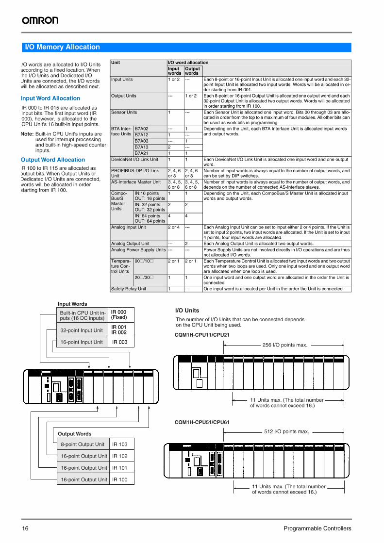
/O words are allocated to I/O Units according to a fixed location. When the I/O Units and Dedicated I/O Units are connected, the I/O words will be allocated as described next.
IR 000 to IR 015 are allocated as input bits. The first input word (IR 000), however, is allocated to the CPU Unit's 16 built-in input points.
Note: Built-in CPU Unit's inputs are used for interrupt processing and built-in high-speed counter inputs.
R 100 to IR 115 are allocated as output bits. When Output Units or Dedicated I/O Units are connected, words will be allocated in order starting from IR 100.
IR 003
IR 101
IR 103
IR 102
IR 100
IR 000 (Fixed)
IR 001 IR 002
Input Words
32-point Input Unit
16-point Input Unit IR 003
Output Words
8-point Output Unit
16-point Output Unit
16-point Output Unit
16-point Output Unit
I/O Units
The number of I/O Units that can be connected depends on the CPU Unit being used.
CQM1H-CPU11/CPU21
256 I/O points max.
CQM1H-CPU51/CPU61
512 I/O points max.
Built-in CPU Unit in-puts (16 DC inputs)
IR 000 (Fixed)
IR 001 IR 002
11 Units max. (The total number of words cannot exceed 16.)
11 Units max. (The total number of words cannot exceed 16.)
16 Programmable Controllers
Pro
gra
mm
able
C
on
tro
llers
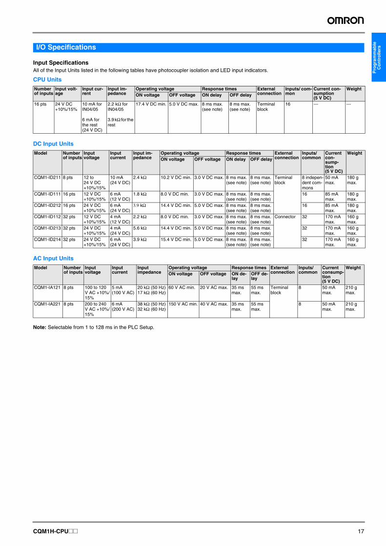
I/O SpecificationsInput SpecificationsAll of the Input Units listed in the following tables have photocoupler isolation and LED input indicators.
CPU Units
DC Input Units
AC Input Units
Note: Selectable from 1 to 128 ms in the PLC Setup.
Number of inputs
Input volt-age
Input cur-rent
Input im-pedance
Operating voltage Response times External connection
Inputs/ com-mon
Current con-sumption (5 V DC)
WeightON voltage OFF voltage ON delay OFF delay
16 pts 24 V DC +10%/15%
10 mA for IN04/05
6 mA for the rest (24 V DC)
2.2 kΩ for IN04/05
3.9 kΩ for the rest
17.4 V DC min. 5.0 V DC max. 8 ms max. (see note)
8 ms max. (see note)
Terminal block
16 --- ---
Model Number of inputs
Input voltage
Input current
Input im-pedance
Operating voltage Response times External connection
Inputs/ common
Current con-sump-tion(5 V DC)
WeightON voltage OFF voltage ON delay OFF delay
CQM1-ID211 8 pts 12 to 24 V DC +10%/15%
10 mA (24 V DC)
2.4 kΩ 10.2 V DC min. 3.0 V DC max. 8 ms max. (see note)
8 ms max. (see note)
Terminal block
8 indepen-dent com-mons
50 mA max.
180 g max.
CQM1-ID111 16 pts 12 V DC +10%/15%
6 mA (12 V DC)
1.8 kΩ 8.0 V DC min. 3.0 V DC max. 8 ms max. (see note)
8 ms max. (see note)
16 85 mA max.
180 g max.
CQM1-ID212 16 pts 24 V DC +10%/15%
6 mA (24 V DC)
3.9 kΩ 14.4 V DC min. 5.0 V DC max. 8 ms max. (see note)
8 ms max. (see note)
16 85 mA max.
180 g max.
CQM1-ID112 32 pts 12 V DC +10%/15%
4 mA (12 V DC)
2.2 kΩ 8.0 V DC min. 3.0 V DC max. 8 ms max. (see note)
8 ms max. (see note)
Connector 32 170 mA max.
160 g max.
CQM1-ID213 32 pts 24 V DC +10%/15%
4 mA (24 V DC)
5.6 kΩ 14.4 V DC min. 5.0 V DC max. 8 ms max. (see note)
8 ms max. (see note)
32 170 mA max.
160 g max.
CQM1-ID214 32 pts 24 V DC +10%/15%
6 mA (24 V DC)
3.9 kΩ 15.4 V DC min. 5.0 V DC max. 8 ms max. (see note)
8 ms max. (see note)
32 170 mA max.
160 g max.
Model Number of inputs
Input voltage
Input current
Input impedance
Operating voltage Response times External connection
Inputs/ common
Current consump-tion(5 V DC)
WeightON voltage OFF voltage ON de-
layOFF de-lay
CQM1-IA121 8 pts 100 to 120 V AC +10%/15%
5 mA (100 V AC)
20 kΩ (50 Hz) 17 kΩ (60 Hz)
60 V AC min. 20 V AC max. 35 ms max.
55 ms max.
Terminal block
8 50 mA max.
210 g max.
CQM1-IA221 8 pts 200 to 240 V AC +10%/15%
6 mA (200 V AC)
38 kΩ (50 Hz) 32 kΩ (60 Hz)
150 V AC min. 40 V AC max. 35 ms max.
55 ms max.
8 50 mA max.
210 g max.
CQM1H-CPU@@ 17
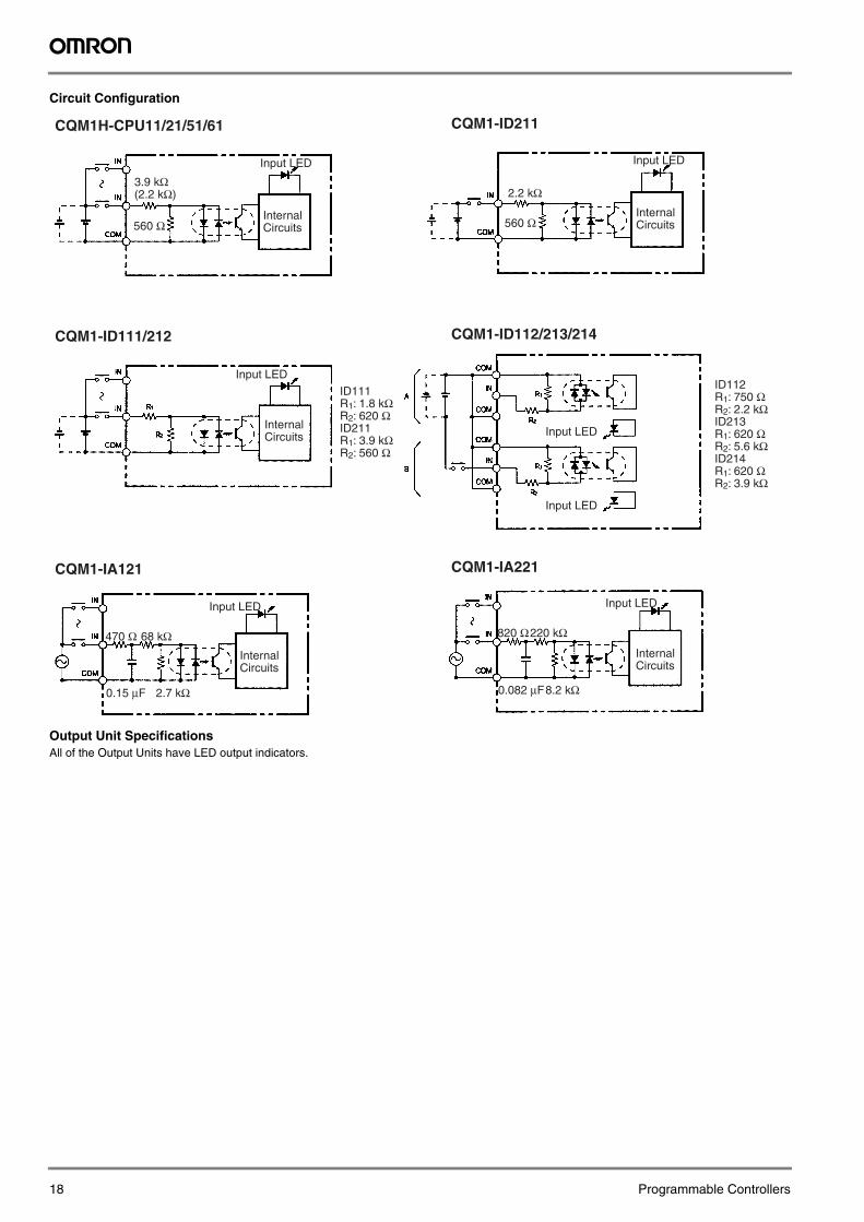
Circuit Configuration
Output Unit SpecificationsAll of the Output Units have LED output indicators.
CQM1H-CPU11/21/51/61
560 Ω
CQM1-ID211
2.2 kΩ
560 Ω
CQM1-ID111/212 CQM1-ID112/213/214
CQM1-IA121 CQM1-IA221
470 Ω
2.7 kΩ0.15 μF
68 kΩ 820 Ω
8.2 kΩ0.082 μF
220 kΩ
3.9 kΩ(2.2 kΩ)
ID111R1: 1.8 kΩR2: 620 ΩID211R1: 3.9 kΩR2: 560 Ω
ID112R1: 750 ΩR2: 2.2 kΩID213R1: 620 ΩR2: 5.6 kΩID214R1: 620 ΩR2: 3.9 kΩ
Input LED
Input LED
Input LED Input LED
Input LED
Input LED
Internal Circuits
Internal Circuits
Internal Circuits
Internal Circuits
Input LED
Internal Circuits
18 Programmable Controllers
Pro
gra
mm
able
C
on
tro
llers
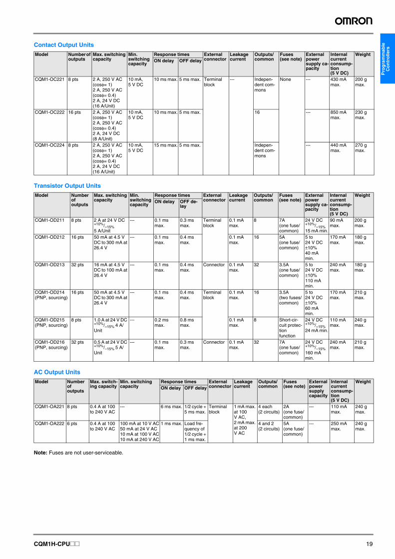
Contact Output Units
Transistor Output Units
AC Output Units
Note: Fuses are not user-serviceable.
Model Number of outputs
Max. switching capacity
Min. switching capacity
Response times External connector
Leakage current
Outputs/common
Fuses(see note)
External power supply ca-pacity
Internal current consump-tion (5 V DC)
WeightON delay OFF delay
CQM1-OC221 8 pts 2 A, 250 V AC (cosφ= 1)2 A, 250 V AC (cosφ= 0.4)2 A, 24 V DC (16 A/Unit)
10 mA, 5 V DC
10 ms max. 5 ms max. Terminal block
--- Indepen-dent com-mons
None --- 430 mA max.
200 g max.
CQM1-OC222 16 pts 2 A, 250 V AC (cosφ= 1)2 A, 250 V AC (cosφ= 0.4)2 A, 24 V DC (8 A/Unit)
10 mA, 5 V DC
10 ms max. 5 ms max. 16 --- 850 mA max.
230 g max.
CQM1-OC224 8 pts 2 A, 250 V AC (cosφ= 1)2 A, 250 V AC (cosφ= 0.4)2 A, 24 V DC (16 A/Unit)
10 mA, 5 V DC
15 ms max. 5 ms max. Indepen-dent com-mons
--- 440 mA max.
270 g max.
Model Number of outputs
Max. switching capacity
Min. switching capacity
Response times External connector
Leakage current
Outputs/common
Fuses(see note)
External power supply ca-pacity
Internal current consump-tion (5 V DC)
WeightON delay OFF de-
lay
CQM1-OD211 8 pts 2 A at 24 V DC +10%/–15% 5 A/Unit
--- 0.1 ms max.
0.3 ms max.
Terminal block
0.1 mA max.
8 7A(one fuse/common)
24 V DC +10%/–15% 15 mA min.
90 mA max.
200 g max.
CQM1-OD212 16 pts 50 mA at 4.5 V DC to 300 mA at 26.4 V
--- 0.1 ms max.
0.4 ms max.
0.1 mA max.
16 5A(one fuse/common)
5 to 24 V DC ±10% 40 mA min.
170 mA max.
180 g max.
CQM1-OD213 32 pts 16 mA at 4.5 V DC to 100 mA at 26.4 V
--- 0.1 ms max.
0.4 ms max.
Connector 0.1 mA max.
32 3.5A(one fuse/common)
5 to 24 V DC ±10% 110 mA min.
240 mA max.
180 g max.
CQM1-OD214 (PNP, sourcing)
16 pts 50 mA at 4.5 V DC to 300 mA at 26.4 V
--- 0.1 ms max.
0.4 ms max.
Terminal block
0.1 mA max.
16 3.5A(two fuses/common)
5 to 24 V DC ±10% 60 mA min.
170 mA max.
210 g max.
CQM1-OD215 (PNP, sourcing)
8 pts 1.0 A at 24 V DC +10%/–15% 4 A/Unit
--- 0.2 ms max.
0.8 ms max.
0.1 mA max.
8 Short-cir-cuit protec-tion function
24 V DC +10%/–15% 24 mA min.
110 mA max.
240 g max.
CQM1-OD216 (PNP, sourcing)
32 pts 0.5 A at 24 V DC +10%/–15% 5 A/Unit
--- 0.1 ms max.
0.3 ms max.
Connector 0.1 mA max.
32 7A(one fuse/common)
24 V DC +10%/–15% 160 mA min.
240 mA max.
210 g max.
Model Number of outputs
Max. switch-ing capacity
Min. switching capacity
Response times External connector
Leakage current
Outputs/common
Fuses(see note)
External power supply capacity
Internal current consump-tion (5 V DC)
WeightON delay OFF delay
CQM1-OA221 8 pts 0.4 A at 100 to 240 V AC
--- 6 ms max. 1/2 cycle + 5 ms max.
Terminal block
1 mA max. at 100 V AC, 2 mA max. at 200 V AC
4 each(2 circuits)
2A(one fuse/common)
--- 110 mA max.
240 g max.
CQM1-OA222 6 pts 0.4 A at 100 to 240 V AC
100 mA at 10 V AC50 mA at 24 V AC10 mA at 100 V AC10 mA at 240 V AC
1 ms max. Load fre-quency of 1/2 cycle + 1 ms max.
4 and 2(2 circuits)
5A(one fuse/common)
--- 250 mA max.
240 g max.
CQM1H-CPU@@ 19
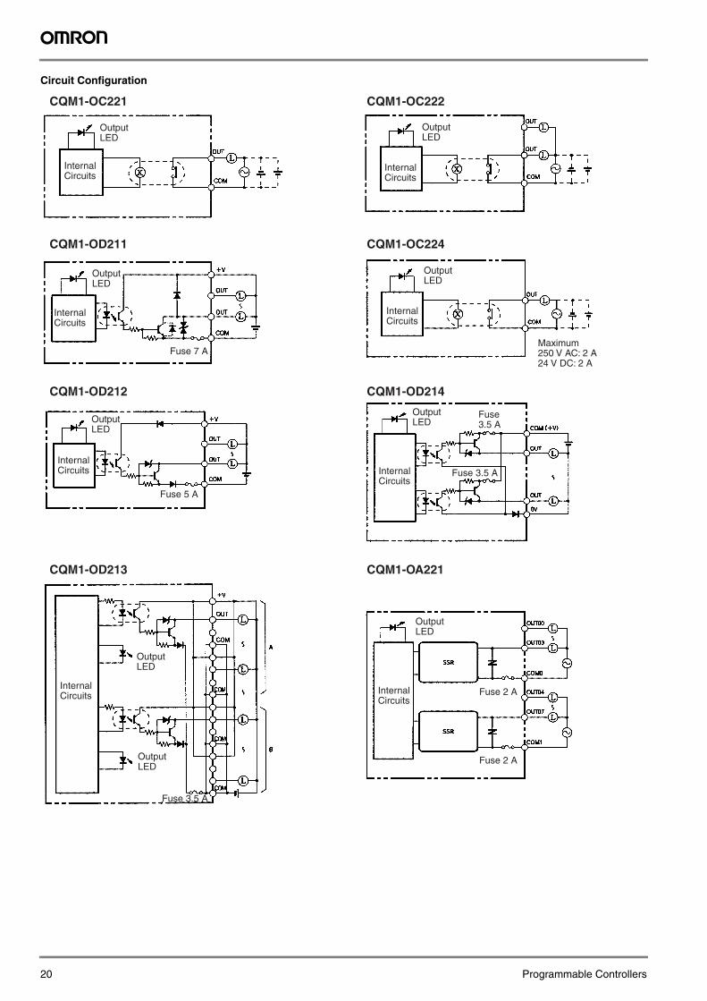
Circuit Configuration
CQM1-OC221 CQM1-OC222
CQM1-OD211 CQM1-OC224
CQM1-OD212 CQM1-OD214
CQM1-OD213 CQM1-OA221
Fuse 5 A
Fuse 3.5 A
Fuse 3.5 A
Fuse 2 A
Fuse 2 A
Fuse 7 A
Internal Circuits
Output LED
Internal Circuits
Output LED
Internal Circuits
Output LED
Internal Circuits
Output LED
Internal Circuits
Output LED
Internal Circuits
Output LED
Internal Circuits
Output LED
Maximum250 V AC: 2 A24 V DC: 2 A
Internal Circuits
Output LED
Output LED
Fuse 3.5 A
20 Programmable Controllers
Pro
gra
mm
able
C
on
tro
llers
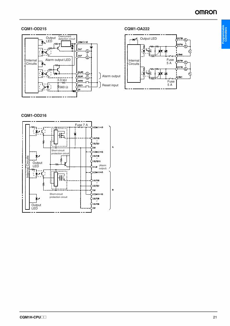
CQM1-OD215 CQM1-OA222CQM1-OD216
3.3 kΩ
560 Ω
Output LED
Fuse 7 A
Inte
rnal
Circ
uits
Alarm output LED
Alarm output
Reset input
Internal Circuits
Output LED
Overcurrent detection circuit
Output LED
Output LED
Short-circuit protection circuit
Short-circuit protection circuit
(Alarm output)
Internal Circuits
Fuse 5 A
Fuse 5 A
CQM1H-CPU@@ 21
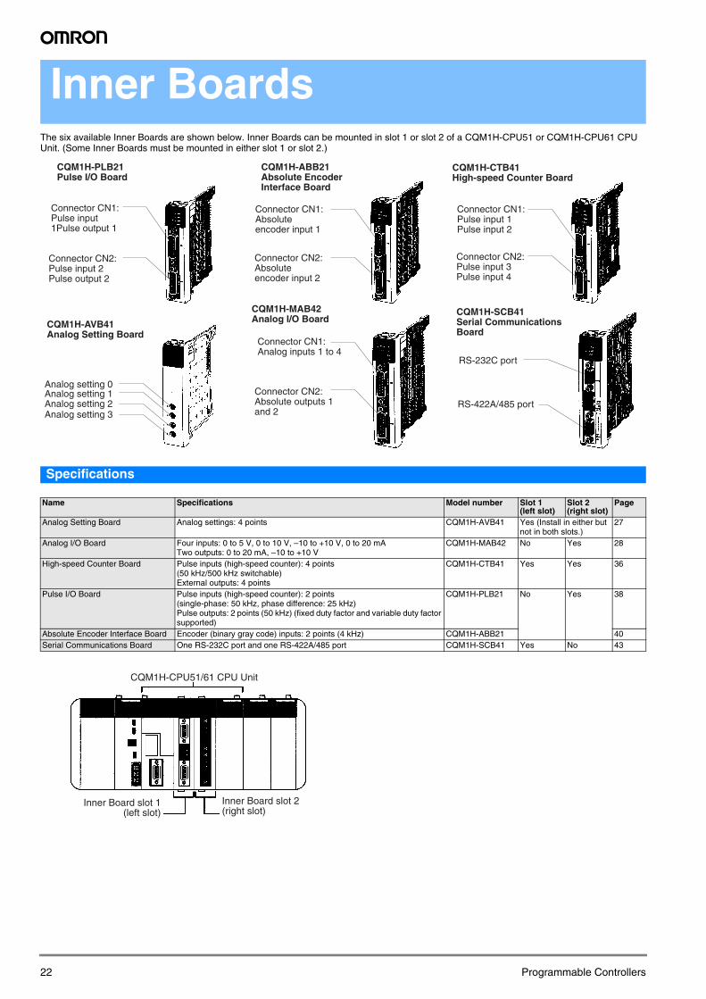
Inner Boards
The six available Inner Boards are shown below. Inner Boards can be mounted in slot 1 or slot 2 of a CQM1H-CPU51 or CQM1H-CPU61 CPU Unit. (Some Inner Boards must be mounted in either slot 1 or slot 2.)Specifications
Name Specifications Model number Slot 1(left slot)
Slot 2(right slot)
Page
Analog Setting Board Analog settings: 4 points CQM1H-AVB41 Yes (Install in either but not in both slots.)
27
Analog I/O Board Four inputs: 0 to 5 V, 0 to 10 V, –10 to +10 V, 0 to 20 mATwo outputs: 0 to 20 mA, –10 to +10 V
CQM1H-MAB42 No Yes 28
High-speed Counter Board Pulse inputs (high-speed counter): 4 points (50 kHz/500 kHz switchable) External outputs: 4 points
CQM1H-CTB41 Yes Yes 36
Pulse I/O Board Pulse inputs (high-speed counter): 2 points (single-phase: 50 kHz, phase difference: 25 kHz)Pulse outputs: 2 points (50 kHz) (fixed duty factor and variable duty factor supported)
CQM1H-PLB21 No Yes 38
Absolute Encoder Interface Board Encoder (binary gray code) inputs: 2 points (4 kHz) CQM1H-ABB21 40Serial Communications Board One RS-232C port and one RS-422A/485 port CQM1H-SCB41 Yes No 43
Analog setting 0Analog setting 1Analog setting 2Analog setting 3
RS-232C port
RS-422A/485 port
CQM1H-PLB21Pulse I/O Board
Connector CN1:Pulse input 1Pulse output 1
Connector CN2:Pulse input 2Pulse output 2
CQM1H-AVB41Analog Setting Board
CQM1H-ABB21Absolute Encoder Interface Board
Connector CN1:Absolute encoder input 1
Connector CN2:Absolute encoder input 2
CQM1H-MAB42Analog I/O Board
Connector CN1:Analog inputs 1 to 4
Connector CN2:Absolute outputs 1 and 2
CQM1H-CTB41High-speed Counter Board
Connector CN1:Pulse input 1Pulse input 2
Connector CN2:Pulse input 3Pulse input 4
CQM1H-SCB41Serial Communications Board
CQM1H-CPU51/61 CPU Unit
Inner Board slot 1 (left slot)
Inner Board slot 2(right slot)
22 Programmable Controllers
ram
mab
le
ntr
olle
rs
Dedicated I/O UnitsPro
gC
o
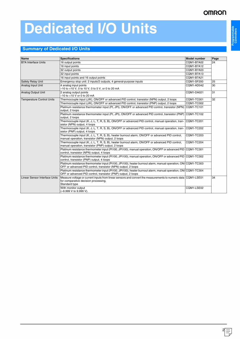
Summary of Dedicated I/O Units
Name Specifications Model number PageB7A Interface Units 16 output points CQM1-B7A02 24
16 input points CQM1-B7A1232 output points CQM1-B7A0332 input points CQM1-B7A1316 input points and 16 output points CQM1-B7A21
Safety Relay Unit Emergency stop unit: 2 inputs/2 outputs, 4 general-purpose inputs CQM1-SF200 25Analog Input Unit 4 analog input points
–10 to +10 V, 0 to 10 V, 0 to 5 V, or 0 to 20 mACQM1-AD042 30
Analog Output Unit 2 analog output points–10 to +10 V or 0 to 20 mA
CQM1-DA021 31
Temperature Control Units Thermocouple input (J/K), ON/OFF or advanced PID control, transistor (NPN) output, 2 loops CQM1-TC001 32Thermocouple input (J/K), ON/OFF or advanced PID control, transistor (PNP) output, 2 loops CQM1-TC002Platinum resistance thermometer input (Pt, JPt), ON/OFF or advanced PID control, transistor (NPN) output, 2 loops
CQM1-TC101
Platinum resistance thermometer input (Pt, JPt), ON/OFF or advanced PID control, transistor (PNP) output, 2 loops
CQM1-TC102
Thermocouple input (K, J, L, T, R, S, B), ON/OFF or advanced PID control, manual operation, tran-sistor (NPN) output, 4 loops
CQM1-TC201
Thermocouple input (K, J, L, T, R, S, B), ON/OFF or advanced PID control, manual operation, tran-sistor (PNP) output, 4 loops
CQM1-TC202
Thermocouple input (K, J, L, T, R, S, B), heater burnout alarm, ON/OFF or advanced PID control, manual operation, transistor (NPN) output, 2 loops
CQM1-TC203
Thermocouple input (K, J, L, T, R, S, B), heater burnout alarm, ON/OFF or advanced PID control, manual operation, transistor (PNP) output, 2 loops
CQM1-TC204
Platinum resistance thermometer input (Pt100, JPt100), manual operation, ON/OFF or advanced PID control, transistor (NPN) output, 4 loops
CQM1-TC301
Platinum resistance thermometer input (Pt100, JPt100), manual operation, ON/OFF or advanced PID control, transistor (PNP) output, 4 loops
CQM1-TC302
Platinum resistance thermometer input (Pt100, JPt100), heater burnout alarm, manual operation, ON/OFF or advanced PID control, transistor (NPN) output, 2 loops
CQM1-TC303
Platinum resistance thermometer input (Pt100, JPt100), heater burnout alarm, manual operation, ON/OFF or advanced PID control, transistor (PNP) output, 2 loops
CQM1-TC304
Linear Sensor Interface Units Measure voltage or current inputs from linear sensors and convert the measurements to numeric data for comparative decision processing.Standard type
CQM1-LSE01 34
With monitor output (–9.999 V to 9.999 V).
CQM1-LSE02
23
("1:1:20578")
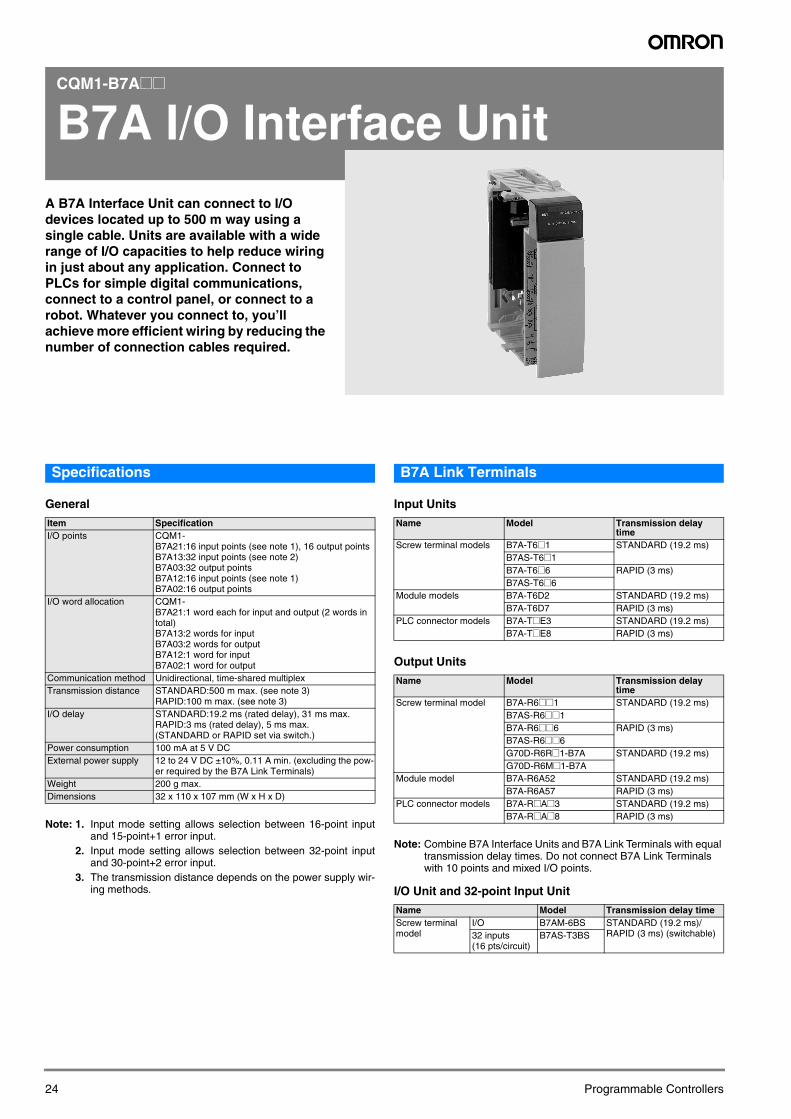
CQM1-B7A@@
B7A I/O Interface Unit
A B7A Interface Unit can connect to I/O devices located up to 500 m way using a single cable. Units are available with a wide range of I/O capacities to help reduce wiring in just about any application. Connect to PLCs for simple digital communications, connect to a control panel, or connect to a robot. Whatever you connect to, you’ll achieve more efficient wiring by reducing the number of connection cables required.24
Specifications
General
Note: 1. Input mode setting allows selection between 16-point inputand 15-point+1 error input.
2. Input mode setting allows selection between 32-point inputand 30-point+2 error input.
3. The transmission distance depends on the power supply wir-ing methods.
B7A Link Terminals
Input Units
Output Units
Note: Combine B7A Interface Units and B7A Link Terminals with equal transmission delay times. Do not connect B7A Link Terminals with 10 points and mixed I/O points.
I/O Unit and 32-point Input Unit
Item SpecificationI/O points CQM1-
B7A21:16 input points (see note 1), 16 output pointsB7A13:32 input points (see note 2)B7A03:32 output pointsB7A12:16 input points (see note 1)B7A02:16 output points
I/O word allocation CQM1-B7A21:1 word each for input and output (2 words in total)B7A13:2 words for inputB7A03:2 words for outputB7A12:1 word for inputB7A02:1 word for output
Communication method Unidirectional, time-shared multiplexTransmission distance STANDARD:500 m max. (see note 3)
RAPID:100 m max. (see note 3)I/O delay STANDARD:19.2 ms (rated delay), 31 ms max.
RAPID:3 ms (rated delay), 5 ms max.(STANDARD or RAPID set via switch.)
Power consumption 100 mA at 5 V DCExternal power supply 12 to 24 V DC ±10%, 0.11 A min. (excluding the pow-
er required by the B7A Link Terminals)Weight 200 g max.Dimensions 32 x 110 x 107 mm (W x H x D)
Name Model Transmission delay time
Screw terminal models B7A-T6@1 STANDARD (19.2 ms)B7AS-T6@1B7A-T6@6 RAPID (3 ms)B7AS-T6@6
Module models B7A-T6D2 STANDARD (19.2 ms)B7A-T6D7 RAPID (3 ms)
PLC connector models B7A-T@E3 STANDARD (19.2 ms)B7A-T@E8 RAPID (3 ms)
Name Model Transmission delay time
Screw terminal model B7A-R6@@1 STANDARD (19.2 ms)B7AS-R6@@1B7A-R6@@6 RAPID (3 ms)B7AS-R6@@6G70D-R6R@1-B7A STANDARD (19.2 ms)G70D-R6M@1-B7A
Module model B7A-R6A52 STANDARD (19.2 ms)B7A-R6A57 RAPID (3 ms)
PLC connector models B7A-R@A@3 STANDARD (19.2 ms)B7A-R@A@8 RAPID (3 ms)
Name Model Transmission delay timeScrew terminal model
I/O B7AM-6BS STANDARD (19.2 ms)/ RAPID (3 ms) (switchable)32 inputs
(16 pts/circuit)B7AS-T3BS
Programmable Controllers
Pro
gra
mm
able
C
on
tro
llers
CQM1-SF200
Safety Relay Unit
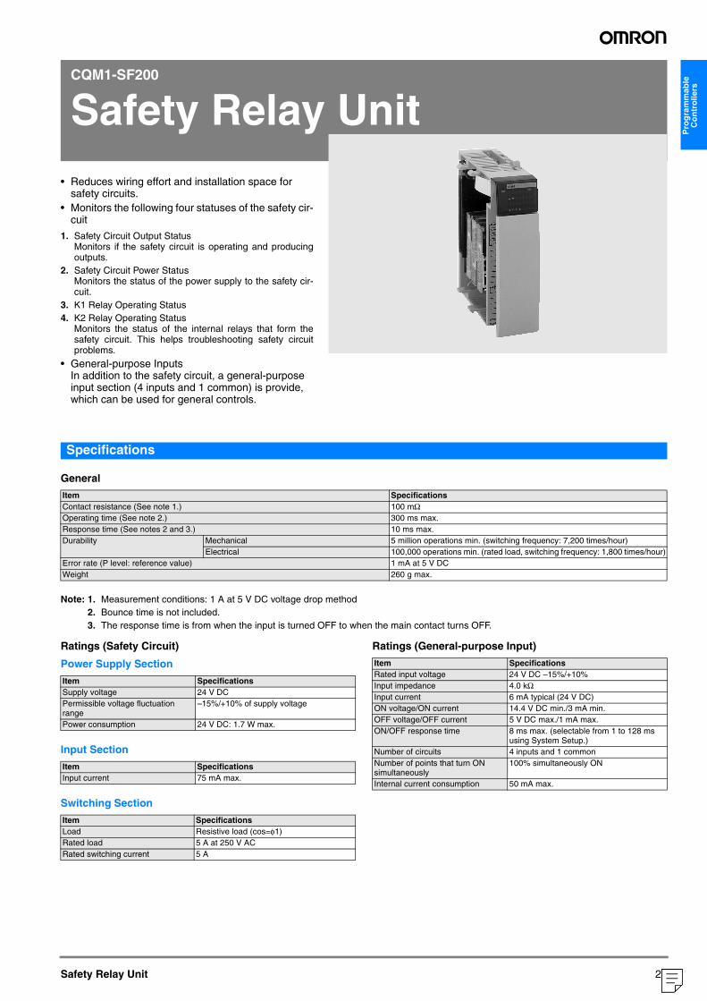
• Reduces wiring effort and installation space forsafety circuits.• Monitors the following four statuses of the safety cir-
cuit
1. Safety Circuit Output Status Monitors if the safety circuit is operating and producingoutputs.
2. Safety Circuit Power StatusMonitors the status of the power supply to the safety cir-cuit.
3. K1 Relay Operating Status4. K2 Relay Operating Status
Monitors the status of the internal relays that form thesafety circuit. This helps troubleshooting safety circuitproblems.
• General-purpose InputsIn addition to the safety circuit, a general-purpose input section (4 inputs and 1 common) is provide, which can be used for general controls.
Safety Relay Unit
Specifications
General
Note: 1. Measurement conditions: 1 A at 5 V DC voltage drop method2. Bounce time is not included.3. The response time is from when the input is turned OFF to when the main contact turns OFF.
Ratings (Safety Circuit)
Power Supply Section
Input Section
Switching Section
Ratings (General-purpose Input)
Item SpecificationsContact resistance (See note 1.) 100 mΩOperating time (See note 2.) 300 ms max.Response time (See notes 2 and 3.) 10 ms max.Durability Mechanical 5 million operations min. (switching frequency: 7,200 times/hour)
Electrical 100,000 operations min. (rated load, switching frequency: 1,800 times/hour)Error rate (P level: reference value) 1 mA at 5 V DCWeight 260 g max.
Item SpecificationsSupply voltage 24 V DCPermissible voltage fluctuation range
–15%/+10% of supply voltage
Power consumption 24 V DC: 1.7 W max.
Item SpecificationsInput current 75 mA max.
Item SpecificationsLoad Resistive load (cos=φ1)Rated load 5 A at 250 V ACRated switching current 5 A
Item SpecificationsRated input voltage 24 V DC –15%/+10%Input impedance 4.0 kΩInput current 6 mA typical (24 V DC)ON voltage/ON current 14.4 V DC min./3 mA min.OFF voltage/OFF current 5 V DC max./1 mA max.ON/OFF response time 8 ms max. (selectable from 1 to 128 ms
using System Setup.)Number of circuits 4 inputs and 1 commonNumber of points that turn ON simultaneously
100% simultaneously ON
Internal current consumption 50 mA max.
25
("1:1:20578")
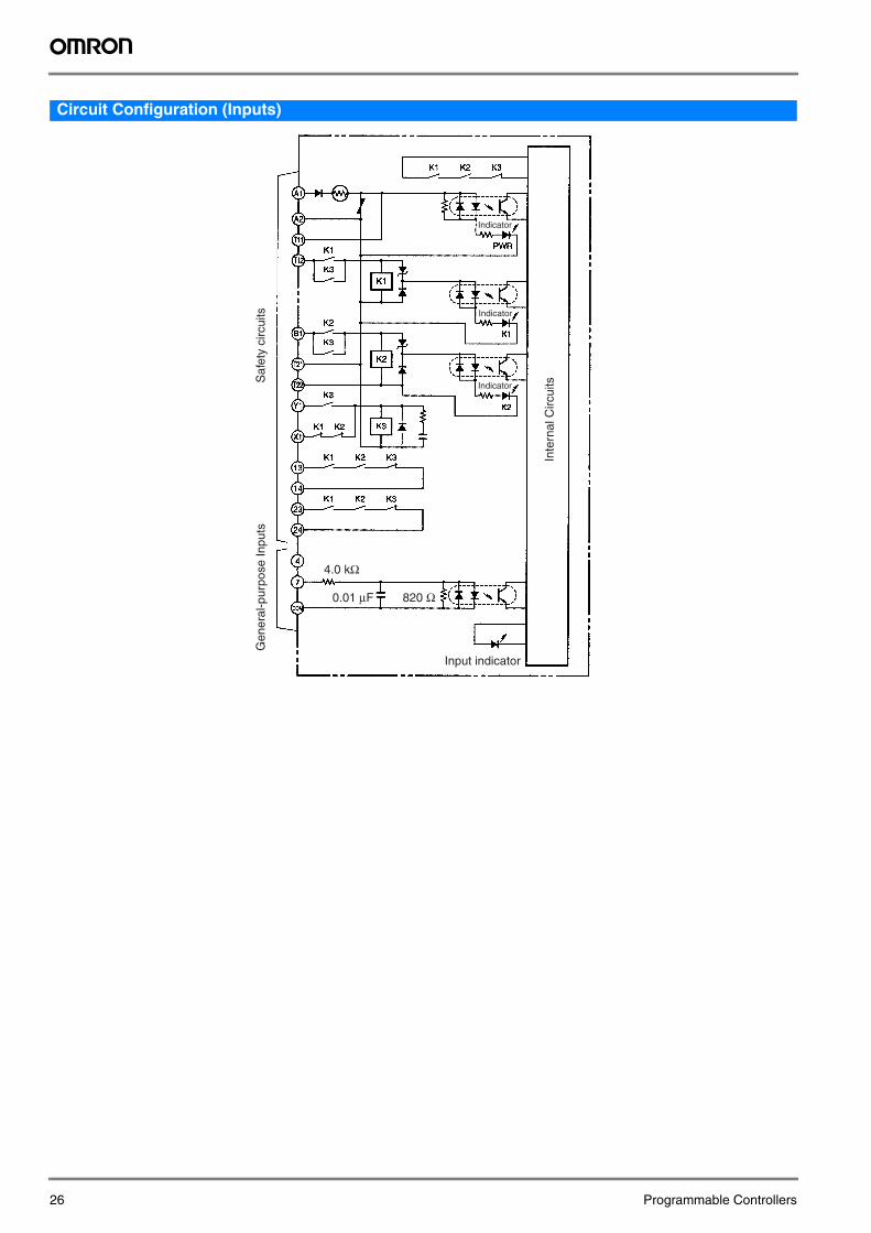
Circuit Configuration (Inputs)
4.0 kΩ
820 Ω0.01 μF
Saf
ety
circ
uits
Gen
eral
-pur
pose
Inpu
ts
Inte
rnal
Circ
uitsIndicator
Input indicator
Indicator
Indicator
26 Programmable Controllers
Pro
gra
mm
able
C
on
tro
llers
CQM1H-AVB41
Analog Setting Board
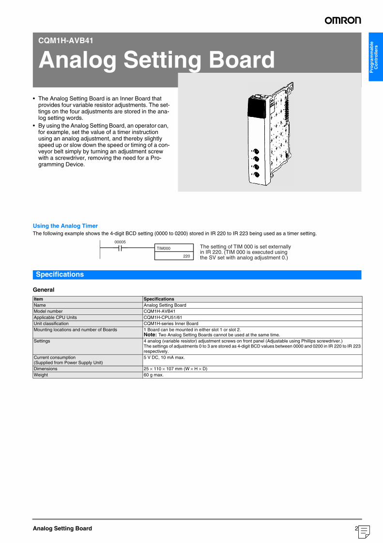
• The Analog Setting Board is an Inner Board thatprovides four variable resistor adjustments. The set-tings on the four adjustments are stored in the ana-log setting words.
• By using the Analog Setting Board, an operator can, for example, set the value of a timer instruction using an analog adjustment, and thereby slightly speed up or slow down the speed or timing of a con-veyor belt simply by turning an adjustment screw with a screwdriver, removing the need for a Pro-gramming Device.
Analog Setting Board
Using the Analog TimerThe following example shows the 4-digit BCD setting (0000 to 0200) stored in IR 220 to IR 223 being used as a timer setting.
Specifications
General
Item SpecificationsName Analog Setting BoardModel number CQM1H-AVB41Applicable CPU Units CQM1H-CPU51/61Unit classification CQM1H-series Inner BoardMounting locations and number of Boards 1 Board can be mounted in either slot 1 or slot 2.
Note: Two Analog Setting Boards cannot be used at the same time.Settings 4 analog (variable resistor) adjustment screws on front panel (Adjustable using Phillips screwdriver.)
The settings of adjustments 0 to 3 are stored as 4-digit BCD values between 0000 and 0200 in IR 220 to IR 223 respectively.
Current consumption (Supplied from Power Supply Unit)
5 V DC, 10 mA max.
Dimensions 25 × 110 × 107 mm (W × H × D)Weight 60 g max.
TIM000
220
00005The setting of TIM 000 is set externally in IR 220. (TIM 000 is executed using the SV set with analog adjustment 0.)
27
("1:1:20578")
CQM1H-MAB42
Analog I/O Board
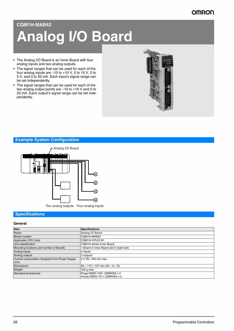
• The Analog I/O Board is an Inner Board with fouranalog inputs and two analog outputs.• The signal ranges that can be used for each of the
four analog inputs are –10 to +10 V, 0 to 10 V, 0 to 5 V, and 0 to 20 mA. Each input’s signal range can be set independently.
• The signal ranges that can be used for each of the two analog output points are –10 to +10 V and 0 to 20 mA. Each output’s signal range can be set inde-pendently.
28
Example System Configuration
Specifications
General
Analog I/O Board
Four analog inputsTwo analog outputs
Item SpecificationsName Analog I/O BoardModel number CQM1H-MAB42Applicable CPU Units CQM1H-CPU51/61Unit classification CQM1H-series Inner BoardMounting locations and number of Boards 1 Board in Inner Board slot 2 (right slot)Analog inputs 4 inputsAnalog outputs 2 outputsCurrent consumption (Supplied from Power Supply Unit)
5 V DC, 400 mA max.
Dimensions 25 × 110 × 107 mm (W × H × D)Weight 100 g max.Standard accessories Plugs:XM2D-1501 (OMRON) x 2
Hoods:XM2S-1511 (OMRON) x 2
Programmable Controllers
Pro
gra
mm
able
C
on
tro
llers
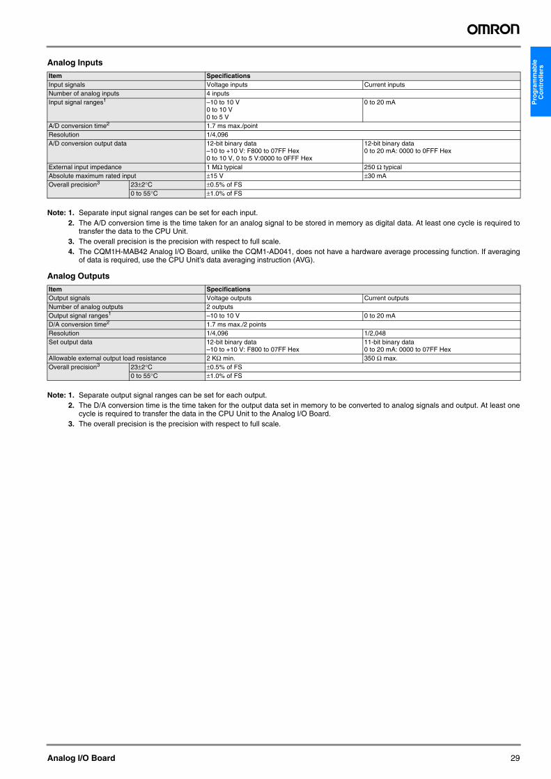
Analog Inputs
Note: 1. Separate input signal ranges can be set for each input.2. The A/D conversion time is the time taken for an analog signal to be stored in memory as digital data. At least one cycle is required to
transfer the data to the CPU Unit.3. The overall precision is the precision with respect to full scale.4. The CQM1H-MAB42 Analog I/O Board, unlike the CQM1-AD041, does not have a hardware average processing function. If averaging
of data is required, use the CPU Unit’s data averaging instruction (AVG).
Analog Outputs
Note: 1. Separate output signal ranges can be set for each output.2. The D/A conversion time is the time taken for the output data set in memory to be converted to analog signals and output. At least one
cycle is required to transfer the data in the CPU Unit to the Analog I/O Board.3. The overall precision is the precision with respect to full scale.
Item SpecificationsInput signals Voltage inputs Current inputsNumber of analog inputs 4 inputsInput signal ranges1 –10 to 10 V
0 to 10 V0 to 5 V
0 to 20 mA
A/D conversion time2 1.7 ms max./pointResolution 1/4,096A/D conversion output data 12-bit binary data
–10 to +10 V: F800 to 07FF Hex0 to 10 V, 0 to 5 V:0000 to 0FFF Hex
12-bit binary data0 to 20 mA: 0000 to 0FFF Hex
External input impedance 1 MΩ typical 250 Ω typicalAbsolute maximum rated input ±15 V ±30 mAOverall precision3 23±2°C ±0.5% of FS
0 to 55°C ±1.0% of FS
Item SpecificationsOutput signals Voltage outputs Current outputsNumber of analog outputs 2 outputsOutput signal ranges1 –10 to 10 V 0 to 20 mAD/A conversion time2 1.7 ms max./2 pointsResolution 1/4,096 1/2,048Set output data 12-bit binary data
–10 to +10 V: F800 to 07FF Hex11-bit binary data0 to 20 mA: 0000 to 07FF Hex
Allowable external output load resistance 2 KΩ min. 350 Ω max.Overall precision3 23±2°C ±0.5% of FS
0 to 55°C ±1.0% of FS
Analog I/O Board 29
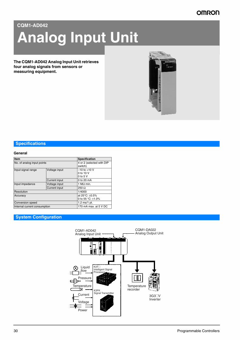
CQM1-AD042
Analog Input Unit
The CQM1-AD042 Analog Input Unit retrieves four analog signals from sensors or measuring equipment.30
Specifications
General
System Configuration
Item SpecificationNo. of analog input points 4 or 2 (selected with DIP
switch)Input signal range Voltage input –10 to +10 V
0 to 10 V0 to 5 V
Current input 0 to 20 mAInput impedance Voltage input 1 MΩ min.
Current input 250 ΩResolution 1/4000Accuracy at 25°C: ±0.5%
0 to 55 °C: ±1.0%Conversion speed 1.2 ms/1 pt.Internal current consumption 170 mA max. at 5 V DC
Pressure
Temperature
Current
Voltage
Power
CQM1-AD042 Analog Input Unit
CQM1-DA022 Analog Output Unit
3G3@V Inverter
Temperature recorder
Liquid flow
K3T@Intelligent Signal Processor
K3FKSignal Transmitter
Programmable Controllers
Pro
gra
mm
able
C
on
tro
llers
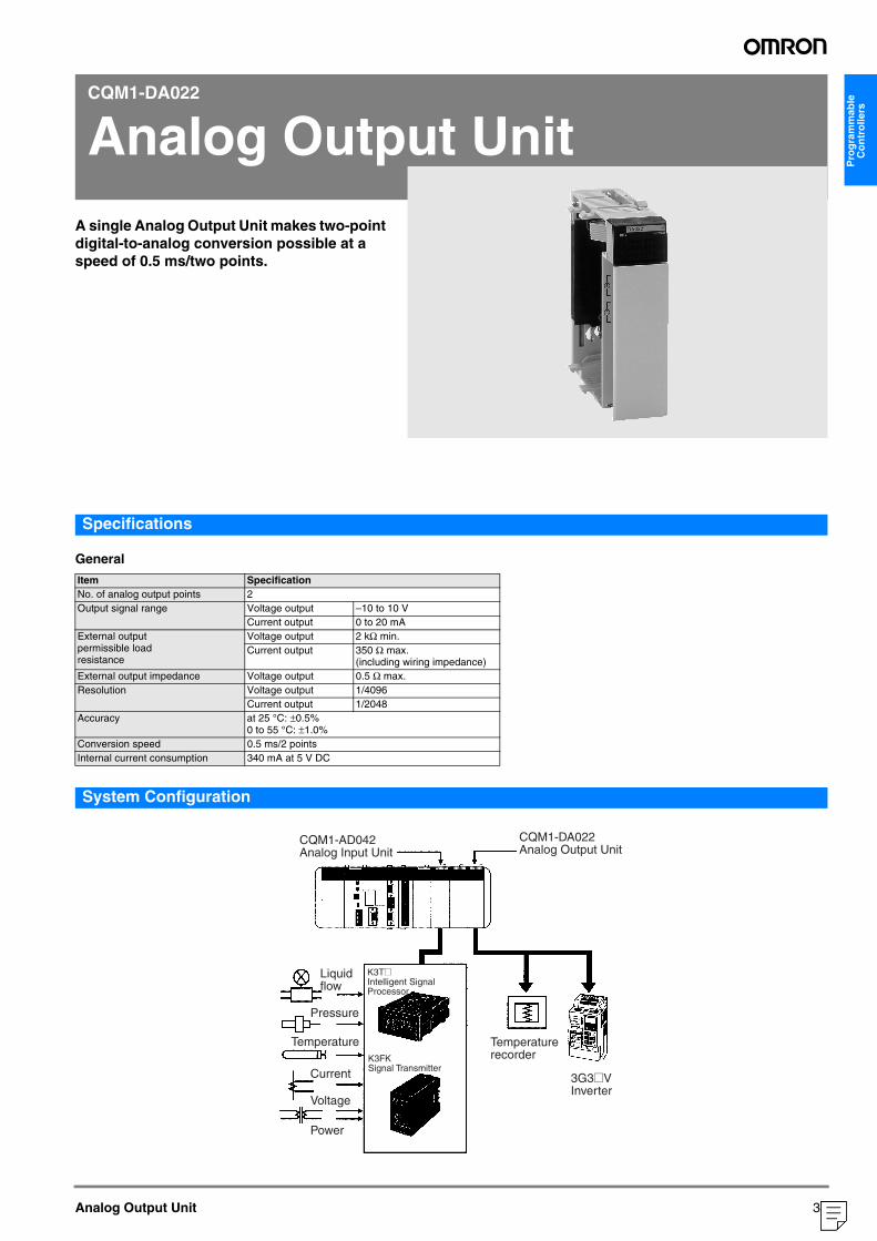
CQM1-DA022
Analog Output Unit
A single Analog Output Unit makes two-point digital-to-analog conversion possible at a speed of 0.5 ms/two points.Analog Output Unit
Specifications
General
System Configuration
Item SpecificationNo. of analog output points 2Output signal range Voltage output –10 to 10 V
Current output 0 to 20 mAExternal output permissible load resistance
Voltage output 2 kΩ min.Current output 350 Ω max.
(including wiring impedance)External output impedance Voltage output 0.5 Ω max.Resolution Voltage output 1/4096
Current output 1/2048Accuracy at 25 °C: ±0.5%
0 to 55 °C: ±1.0%Conversion speed 0.5 ms/2 pointsInternal current consumption 340 mA at 5 V DC
Pressure
Temperature
Current
Voltage
Power
CQM1-AD042 Analog Input Unit
CQM1-DA022 Analog Output Unit
3G3@V Inverter
Temperature recorder
Liquid flow
K3T@Intelligent Signal Processor
K3FKSignal Transmitter
31
("1:1:20578")
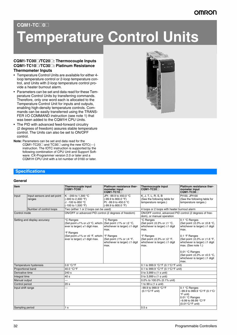
CQM1-TC@0@
Temperature Control Units
CQM1-TC00@/TC20@: Thermocouple InputsCQM1-TC10@/TC30@: Platinum Resistance Thermometer Inputs• Temperature Control Units are available for either 4-loop temperature control or 2-loop temperature con-trol, and Units with 2-loop temperature control pro-vide a heater burnout alarm.
• Parameters can be set and data read for these Tem-perature Control Units by transferring commands. Therefore, only one word each is allocated to the Temperature Control Unit for inputs and outputs, enabling high-density temperature controls. Com-mands can be easily transferred using the TRANS-FER I/O COMMAND instruction (see note 1) that was been added to the CQM1H CPU Units.
• The PID with advanced feed-forward circuitry (2 degrees of freedom) assures stable temperature control. The Units can also be set to ON/OFF control.
Note: Parameters can be set and data read for the CQM1-TC20@ and TC30@ using the new IOTC(−−) instruction. The IOTC instruction is supported by the following combination of CPU Unit and Support Soft-ware: CX-Programmer version 2.0 or later and a CQM1H CPU Unit with a lot number of 0160 or later.
32
Specifications
General
Item Thermocouple inputCQM1-TC00@
Platinum resistance ther-mometer inputCQM1-TC10@
Thermocouple inputCQM1-TC20@
Platinum resistance ther-mometer inputCQM1-TC30@
Input Input sensors and set point ranges
K: –200 to 1,300 °C (-300 to 2,300 °F)J: -100 to 850 °C (-100 to 1,500 °F)
JPt: -99.9 to 450.0 °C (-99.9 to 800.0 °F)Pt: -99.9 to 450.0 °C (-99.9 to 800.0 °F)
K, J, T, L, R, S, B(See the following table for temperature ranges.)
Pt100, JPt100(See the following table for temperature ranges.)
Number of control loops Two (either 1 or 2 loops can be used) 4 loops or 2 loops with heater burnout alarmControl mode ON/OFF or advanced PID control (2 degrees of freedom) ON/OFF control, advanced PID control (2 degrees of free-
dom), or manual operationSetting and display accuracy °C Ranges
(Set point ±1% or ±3 °C, which-ever is larger) ±1 digit max.
°F Ranges (Set point ±1% or ±6 °F, which-ever is larger) ±1 digit max.
°C Ranges(Set point ±1% or ±2 °C, whichever is larger) ±1 digit max.
°F Ranges (Set point ±1% or ±4 °F, whichever is larger) ±1 digit max.
°C Ranges(Set point ±0.3% or ±1 °C, whichever is larger) ±1 digit max.
°F Ranges (Set point ±0.3% or ±2 °F, whichever is larger) ±1 digit max.
0.1 °C Ranges (Set point ±0.3% or ±0.8 °C, whichever is larger) ±1 digit max.
0.1 °F Ranges (Set point ±0.3% or ±1.6 °F, whichever is larger) ±1 digit max. (See note 1.)
0.01 °C Ranges (Set point ±0.3% or ±0.5 °C, whichever is larger) ±1 digit max.
Temperature hysteresis 0.8 °C/°F 0.1 to 999.9 °C/°F (0.1°C/°F unit)Proportional band 40.0 °C/°F 0.1 to 999.9 °C/°F (0.1°C/°F unit)Derivative time 240 s 0 to 3,999 s (1 s unit)Integral time 40 s 0 to 3,999 s (1 s unit)Manual output --- 0.0% to 100.0% (0.1% unit)Control period 20 s 1 to 99 s (1 s unit)Input shift range --- –99.9 to 999.9 °C/°F
(0.1°C/°F unit)0.1 °C Ranges–99.9 to 999.9 °C/°F (0.1°C/°F unit)0.01 °C Ranges–9.99 to 99.99 °C/°F (0.01°C/°F unit)
Sampling period 1 s 0.5 s
Programmable Controllers
Pro
gra
mm
able
C
on
tro
llers
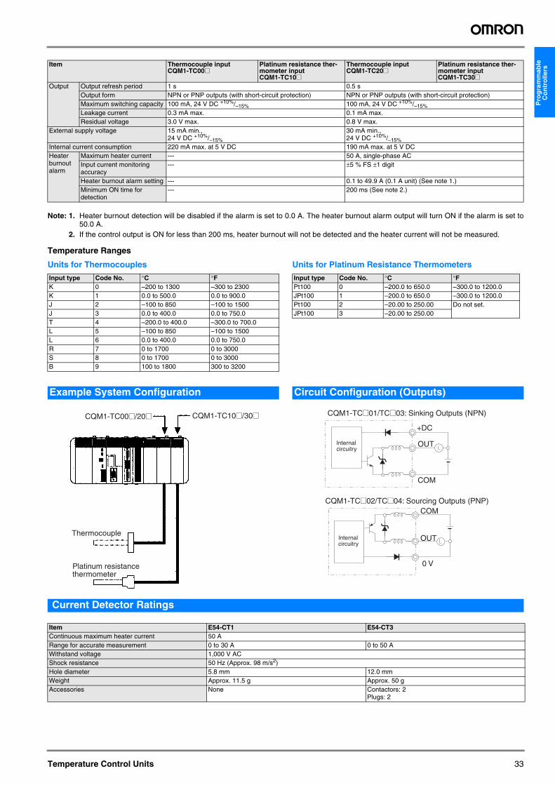
Note: 1. Heater burnout detection will be disabled if the alarm is set to 0.0 A. The heater burnout alarm output will turn ON if the alarm is set to50.0 A.
2. If the control output is ON for less than 200 ms, heater burnout will not be detected and the heater current will not be measured.
Temperature Ranges
Units for Thermocouples Units for Platinum Resistance Thermometers
Current Detector Ratings
Output Output refresh period 1 s 0.5 sOutput form NPN or PNP outputs (with short-circuit protection) NPN or PNP outputs (with short-circuit protection)Maximum switching capacity 100 mA, 24 V DC +10%/–15% 100 mA, 24 V DC +10%/–15%Leakage current 0.3 mA max. 0.1 mA max.Residual voltage 3.0 V max. 0.8 V max.
External supply voltage 15 mA min., 24 V DC +10%/–15%
30 mA min., 24 V DC +10%/–15%
Internal current consumption 220 mA max. at 5 V DC 190 mA max. at 5 V DCHeater burnout alarm
Maximum heater current --- 50 A, single-phase ACInput current monitoring accuracy
--- ±5 % FS ±1 digit
Heater burnout alarm setting --- 0.1 to 49.9 A (0.1 A unit) (See note 1.)Minimum ON time for detection
--- 200 ms (See note 2.)
Item Thermocouple inputCQM1-TC00@
Platinum resistance ther-mometer inputCQM1-TC10@
Thermocouple inputCQM1-TC20@
Platinum resistance ther-mometer inputCQM1-TC30@
Input type Code No. °C °FK 0 –200 to 1300 –300 to 2300K 1 0.0 to 500.0 0.0 to 900.0J 2 –100 to 850 –100 to 1500J 3 0.0 to 400.0 0.0 to 750.0T 4 –200.0 to 400.0 –300.0 to 700.0L 5 –100 to 850 –100 to 1500L 6 0.0 to 400.0 0.0 to 750.0R 7 0 to 1700 0 to 3000S 8 0 to 1700 0 to 3000B 9 100 to 1800 300 to 3200
Input type Code No. °C °FPt100 0 –200.0 to 650.0 –300.0 to 1200.0JPt100 1 –200.0 to 650.0 –300.0 to 1200.0Pt100 2 –20.00 to 250.00 Do not set.JPt100 3 –20.00 to 250.00
Example System Configuration
CQM1-TC00@/20@ CQM1-TC10@/30@
Thermocouple
Platinum resistance thermometer
Circuit Configuration (Outputs)
+DC
OUT
COM
COM
OUT
0 V
CQM1-TC@01/TC@03: Sinking Outputs (NPN)
CQM1-TC@02/TC@04: Sourcing Outputs (PNP)
Internal circuitry
Internal circuitry
Item E54-CT1 E54-CT3Continuous maximum heater current 50 ARange for accurate measurement 0 to 30 A 0 to 50 AWithstand voltage 1,000 V ACShock resistance 50 Hz (Approx. 98 m/s2)Hole diameter 5.8 mm 12.0 mmWeight Approx. 11.5 g Approx. 50 gAccessories None Contactors: 2
Plugs: 2
Temperature Control Units 33
CQM1-LSE0@
Linear Sensor Interface Units
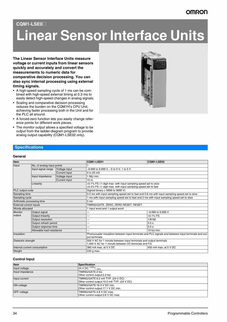
The Linear Sensor Interface Units measure voltage or current inputs from linear sensors quickly and accurately and convert the measurements to numeric data for comparative decision processing. You can also sync internal processing using external timing signals.• A high-speed sampling cycle of 1 ms can be com-bined with high-speed external timing at 0.3 ms to easily detect high-speed changes in analog signals.
• Scaling and comparative decision processing reduces the burden on the CQM1H’s CPU Unit, achieving faster processing both in the Unit and for the PLC all around.
• A forced-zero function lets you easily change refer-ence points for different work pieces.
• The monitor output allows a specified voltage to be output from the ladder-diagram program to provide analog output capability (CQM1-LSE02 only).
34
Specifications
General
Control Input
Item CQM1-LSE01 CQM1-LSE02Input No. of analog input points 1
Input signal range Voltage input –9.999 to 9.999 V, –5 to 5 V, 1 to 5 VCurrent input 4 to 20 mA
Input impedance Voltage input 1 MΩ min.Current input 10 Ω
Linearity ±0.1% FS ±1 digit max. with input sampling speed set to slow±0.5% FS ±1 digit max. with input sampling speed set to fast
PLC output code Signed binary (–9999 to 9999 V)Sampling time 0.3 ms with input sampling speed set to fast and 0.6 ms with input sampling speed set to slowSampling cycle 1 ms with input sampling speed set to fast and 2 ms with input sampling speed set to slowArithmetic processing time 5 msExternal control inputs TIMING/GATE, ZERO, ZERO RESET, RESETWords allocated 1 input word and 1 output wordMonitor output
Output signal --- –9.999 to 9.999 VOutput linearity --- ±0.1% FSOutput resolution --- 1/8192Output refresh period --- 0.5 sOutput response time --- 0.5 sAllowable load resistance --- 10 kΩ min.
Insulation Photocoupler insulation between input terminals and PLC signals and between input terminals and out-put terminals.
Dielectric strength 500 V AC for 1 minute between input terminals and output terminals1,000 V AC for 1 minute between I/O terminals and FG
Internal current consumption 380 mA max. at 5 V DC 450 mA max. at 5 V DC Weight 230 g max.
Item SpecificationInput voltage 24 V DC +10%/–15%Input impedance TIMING/GATE:2 kΩ
Other control output:2.2 kΩInput current TIMING/GATE:9.2 mA TYP. (24 V DC)
Other control output:10.0 mA TYP. (24 V DC)ON voltage TIMING/GATE:16.3 V DC min.
Other control output:17.1 V DC min.OFF voltage TIMING/GATE:3.8 V DC max.
Other control output:3.6 V DC max.
Programmable Controllers
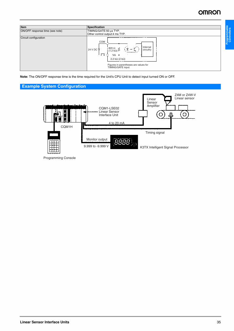
Pro
gra
mm
able
C
on
tro
llers
Note: The ON/OFF response time is the time required for the Unit’s CPU Unit to detect input turned ON or OFF.
Example System Configuration
ON/OFF response time (see note) TIMING/GATE:50 μs TYP.Other control output:4 ms TYP.
Circuit configuration
Item Specification
COM
24 V DC
2.2 kΩ (2 kΩ)
820 Ω(1.2 kΩ)
Figures in parentheses are values for TIMING/GATE input.
Internal circuitry
CQM1H
Programming Console
4 to 20 mA
Monitor output
Timing signal
K3TX Intelligent Signal Processor9.999 to -9.999 V
CQM1-LSE02Linear Sensor Interface Unit
Z4M or Z4W-V Linear sensorLinear
Sensor Amplifier
Linear Sensor Interface Units 35
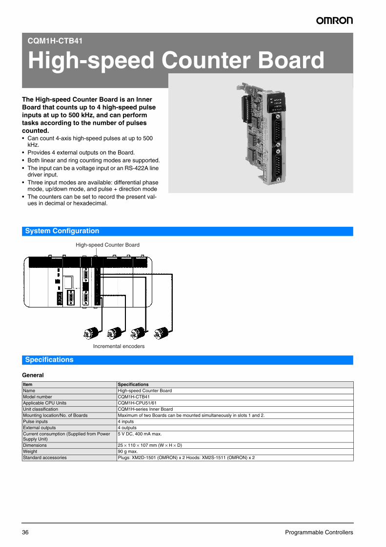
CQM1H-CTB41
High-speed Counter Board
The High-speed Counter Board is an Inner Board that counts up to 4 high-speed pulse inputs at up to 500 kHz, and can perform tasks according to the number of pulses counted.• Can count 4-axis high-speed pulses at up to 500kHz.• Provides 4 external outputs on the Board.• Both linear and ring counting modes are supported.• The input can be a voltage input or an RS-422A line
driver input.• Three input modes are available: differential phase
mode, up/down mode, and pulse + direction mode• The counters can be set to record the present val-
ues in decimal or hexadecimal.
36
System Configuration
Specifications
General
High-speed Counter Board
Incremental encoders
Item SpecificationsName High-speed Counter BoardModel number CQM1H-CTB41Applicable CPU Units CQM1H-CPU51/61Unit classification CQM1H-series Inner BoardMounting location/No. of Boards Maximum of two Boards can be mounted simultaneously in slots 1 and 2.Pulse inputs 4 inputs External outputs 4 outputsCurrent consumption (Supplied from Power Supply Unit)
5 V DC, 400 mA max.
Dimensions 25 × 110 × 107 mm (W × H × D)Weight 90 g max.Standard accessories Plugs: XM2D-1501 (OMRON) x 2 Hoods: XM2S-1511 (OMRON) x 2
Programmable Controllers
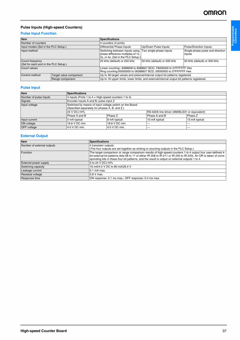
Pro
gra
mm
able
C
on
tro
llers
Pulse Inputs (High-speed Counters)
Pulse Input Function
Pulse Input
External Output
Item SpecificationsNumber of counters 4 counters (4 ports)Input modes (Set in the PLC Setup.) Differential Phase Inputs Up/Down Pulse Inputs Pulse/Direction InputsInput method Switching between inputs using
phase difference multiples of 1x, 2x, or 4x. (Set in the PLC Setup.)
Two single-phase inputs Single-phase pulse and direction inputs
Count frequency (Set for each port in the PLC Setup.)
25 kHz (default) or 250 kHz 50 kHz (default) or 500 kHz 50 kHz (default) or 500 kHz
Count values Linear counting:–8388608 to 8388607 BCD, F8000000 to 07FFFFFF HexRing counting:00000000 to 08388607 BCD, 00000000 to 07FFFFFF Hex
Control method Target value comparison Up to 48 target values and external/internal output bit patterns registered. Range comparison Up to 16 upper limits, lower limits, and external/internal output bit patterns registered.
Item SpecificationsNumber of pulse inputs 4 inputs (Ports 1 to 4 = High-speed counters 1 to 4)Signals Encoder inputs A and B; pulse input ZInput voltage Switched by means of input voltage switch on the Board
(Specified separately for phases A, B, and Z.)24 V DC±10% RS-422A line driver (AM26LS31 or equivalent)Phase A and B Phase Z Phase A and B Phase Z
Input current 5 mA typical 8 mA typical 10 mA typical 13 mA typicalON voltage 19.6 V DC min. 18.6 V DC min. --- ---OFF voltage 4.0 V DC min. 4.0 V DC min. --- ---
Item SpecificationsNumber of external outputs 4 transistor outputs
(The four outputs are set together as sinking or sourcing outputs in the PLC Setup.)Function The target comparison or range comparison results of high-speed counters 1 to 4 output four user-defined 4-
bit external bit patterns (bits 08 to 11 of either IR 208 to IR 211 or IR 240 to IR 243). An OR is taken of corre-sponding bits in these four bit patterns, and the result is output on external outputs 1 to 4.
External power supply 5 to 24 V DC±10%Switching capacity 16 mA/4.5 V DC to 80 mA/26.4 VLeakage current 0.1 mA max.Residual voltage 0.8 V max.Response time ON response: 0.1 ms max.; OFF response: 0.4 ms max.
High-speed Counter Board 37
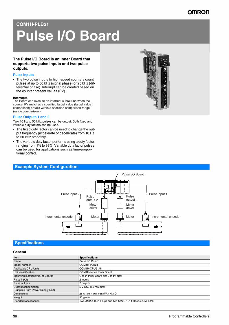
CQM1H-PLB21
Pulse I/O Board
The Pulse I/O Board is an Inner Board that supports two pulse inputs and two pulse outputs.Pulse Inputs• The two pulse inputs to high-speed counters count
pulses at up to 50 kHz (signal phase) or 25 kHz (dif-ferential phase). Interrupt can be created based on the counter present values (PV).
InterruptsThe Board can execute an interrupt subroutine when the counter PV matches a specified target value (target value comparison) or falls within a specified comparison range (range comparison.)
Pulse Outputs 1 and 2Two 10 Hz to 50 kHz pulses can be output. Both fixed and variable duty factors can be used.
• The fixed duty factor can be used to change the out-put frequency (accelerate or decelerate) from 10 Hz to 50 kHz smoothly.
• The variable duty factor performs using a duty factor ranging from 1% to 99%. Variable duty factor pulses can be used for applications such as time-propor-tional control.
38
Example System Configuration
Specifications
General
Item SpecificationsName Pulse I/O BoardModel number CQM1H-PLB21Applicable CPU Units CQM1H-CPU51/61Unit classification CQM1H-series Inner BoardMounting locations/No. of Boards One in Inner Board slot 2 (right slot)Pulse inputs 2 inputsPulse outputs 2 outputsCurrent consumption (Supplied from Power Supply Unit)
5 V DC, 160 mA max.
Dimensions 25 × 110 × 107 mm (W × H × D)Weight 90 g max.Standard accessories Two XM2D-1501 Plugs and two XM2S-1511 Hoods (OMRON)
Pulse I/O Board
Pulse input 2
Incremental encoder Motor Motor
Pulse input 1
Incremental encode
Pulse output 2
Pulse output 1
Motor driver
Motor driver
Programmable Controllers
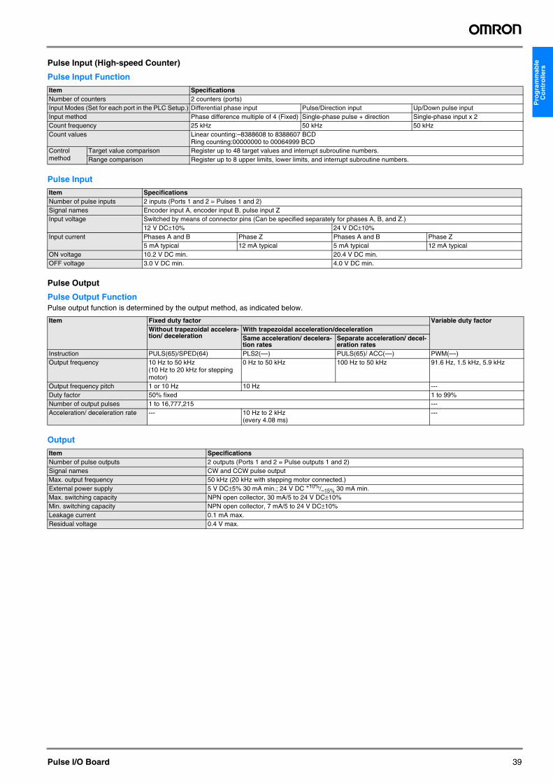
Pro
gra
mm
able
C
on
tro
llers
Pulse Input (High-speed Counter)
Pulse Input Function
Pulse Input
Pulse Output
Pulse Output FunctionPulse output function is determined by the output method, as indicated below.
Output
Item SpecificationsNumber of counters 2 counters (ports)Input Modes (Set for each port in the PLC Setup.) Differential phase input Pulse/Direction input Up/Down pulse inputInput method Phase difference multiple of 4 (Fixed) Single-phase pulse + direction Single-phase input x 2Count frequency 25 kHz 50 kHz 50 kHzCount values Linear counting:–8388608 to 8388607 BCD
Ring counting:00000000 to 00064999 BCDControl method
Target value comparison Register up to 48 target values and interrupt subroutine numbers.Range comparison Register up to 8 upper limits, lower limits, and interrupt subroutine numbers.
Item SpecificationsNumber of pulse inputs 2 inputs (Ports 1 and 2 = Pulses 1 and 2)Signal names Encoder input A, encoder input B, pulse input ZInput voltage Switched by means of connector pins (Can be specified separately for phases A, B, and Z.)
12 V DC±10% 24 V DC±10%Input current Phases A and B Phase Z Phases A and B Phase Z
5 mA typical 12 mA typical 5 mA typical 12 mA typicalON voltage 10.2 V DC min. 20.4 V DC min.OFF voltage 3.0 V DC min. 4.0 V DC min.
Item Fixed duty factor Variable duty factorWithout trapezoidal accelera-tion/ deceleration
With trapezoidal acceleration/decelerationSame acceleration/ decelera-tion rates
Separate acceleration/ decel-eration rates
Instruction PULS(65)/SPED(64) PLS2(––) PULS(65)/ ACC(––) PWM(––)Output frequency 10 Hz to 50 kHz
(10 Hz to 20 kHz for stepping motor)
0 Hz to 50 kHz 100 Hz to 50 kHz 91.6 Hz, 1.5 kHz, 5.9 kHz
Output frequency pitch 1 or 10 Hz 10 Hz ---Duty factor 50% fixed 1 to 99%Number of output pulses 1 to 16,777,215 ---Acceleration/ deceleration rate --- 10 Hz to 2 kHz
(every 4.08 ms)---
Item SpecificationsNumber of pulse outputs 2 outputs (Ports 1 and 2 = Pulse outputs 1 and 2)Signal names CW and CCW pulse outputMax. output frequency 50 kHz (20 kHz with stepping motor connected.)External power supply 5 V DC±5% 30 mA min.; 24 V DC +10%/–15% 30 mA min.Max. switching capacity NPN open collector, 30 mA/5 to 24 V DC±10%Min. switching capacity NPN open collector, 7 mA/5 to 24 V DC±10%Leakage current 0.1 mA max.Residual voltage 0.4 V max.
Pulse I/O Board 39
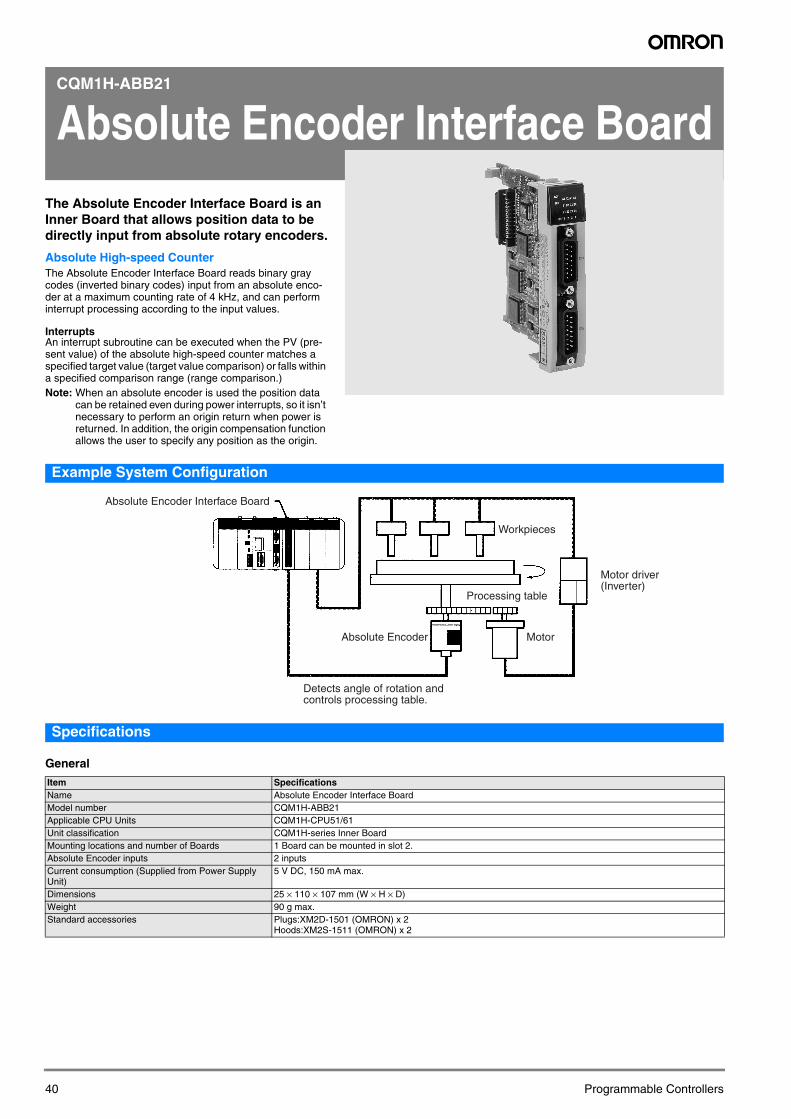
CQM1H-ABB21
Absolute Encoder Interface Board
The Absolute Encoder Interface Board is an Inner Board that allows position data to be directly input from absolute rotary encoders.Absolute High-speed CounterThe Absolute Encoder Interface Board reads binary gray codes (inverted binary codes) input from an absolute enco-der at a maximum counting rate of 4 kHz, and can perform interrupt processing according to the input values.
InterruptsAn interrupt subroutine can be executed when the PV (pre-sent value) of the absolute high-speed counter matches a specified target value (target value comparison) or falls within a specified comparison range (range comparison.)Note: When an absolute encoder is used the position data
can be retained even during power interrupts, so it isn’t necessary to perform an origin return when power is returned. In addition, the origin compensation function allows the user to specify any position as the origin.
40
Example System Configuration
Specifications
General
Item SpecificationsName Absolute Encoder Interface BoardModel number CQM1H-ABB21Applicable CPU Units CQM1H-CPU51/61Unit classification CQM1H-series Inner BoardMounting locations and number of Boards 1 Board can be mounted in slot 2.Absolute Encoder inputs 2 inputsCurrent consumption (Supplied from Power Supply Unit)
5 V DC, 150 mA max.
Dimensions 25 × 110 × 107 mm (W × H × D)Weight 90 g max.Standard accessories Plugs:XM2D-1501 (OMRON) x 2
Hoods:XM2S-1511 (OMRON) x 2
Absolute Encoder Interface Board
Workpieces
Processing table
Absolute Encoder Motor
Motor driver (Inverter)
Detects angle of rotation and controls processing table.
Programmable Controllers
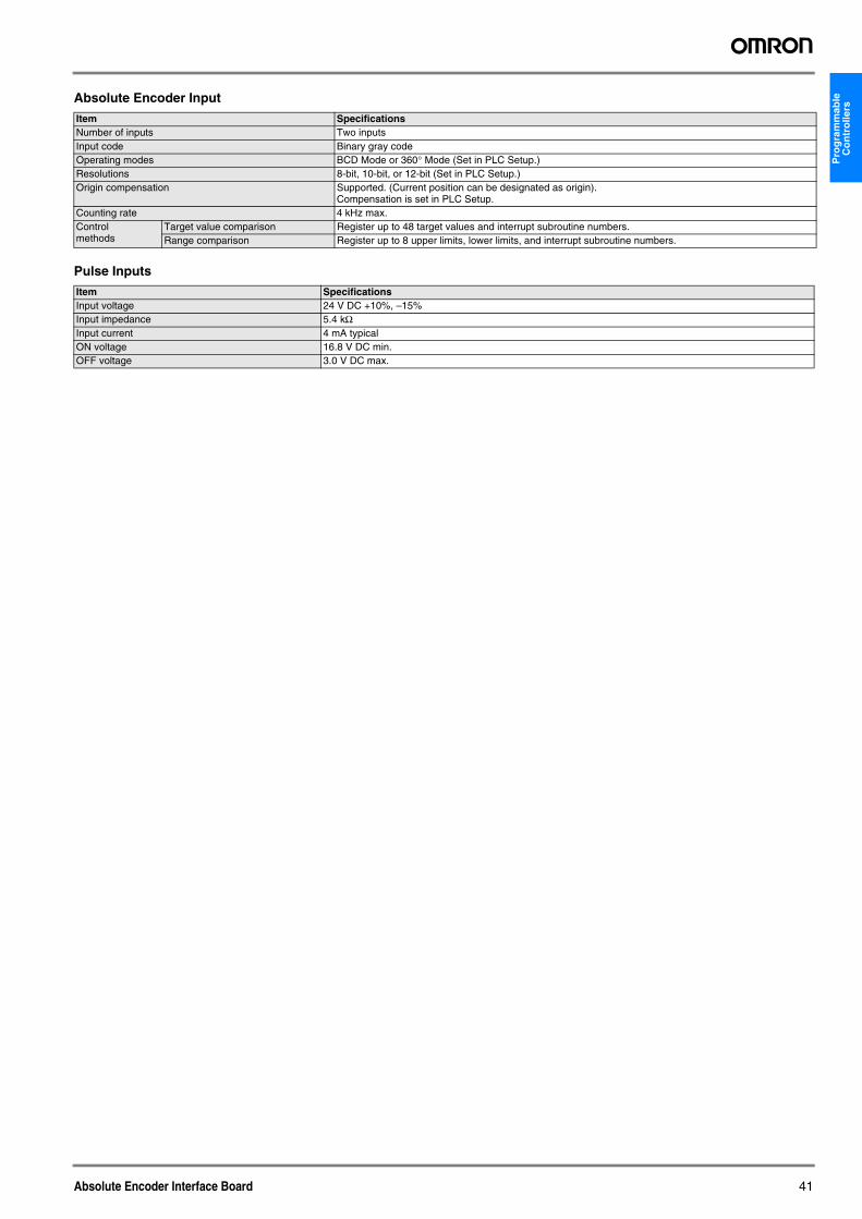
Pro
gra
mm
able
C
on
tro
llers
Absolute Encoder Input
Pulse Inputs
Item SpecificationsNumber of inputs Two inputsInput code Binary gray codeOperating modes BCD Mode or 360° Mode (Set in PLC Setup.)Resolutions 8-bit, 10-bit, or 12-bit (Set in PLC Setup.)Origin compensation Supported. (Current position can be designated as origin).
Compensation is set in PLC Setup.Counting rate 4 kHz max.Control methods
Target value comparison Register up to 48 target values and interrupt subroutine numbers.Range comparison Register up to 8 upper limits, lower limits, and interrupt subroutine numbers.
Item SpecificationsInput voltage 24 V DC +10%, –15%Input impedance 5.4 kΩInput current 4 mA typicalON voltage 16.8 V DC min.OFF voltage 3.0 V DC max.
Absolute Encoder Interface Board 41
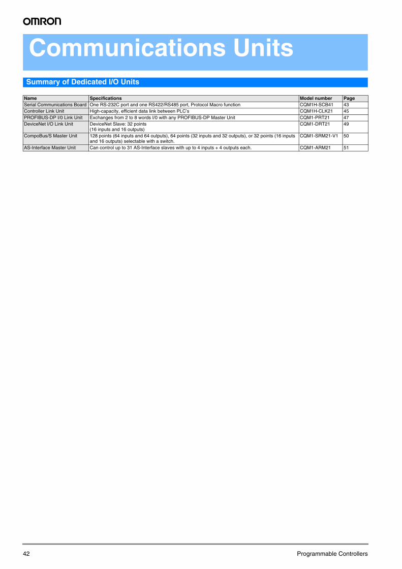
Communications Units
Summary of Dedicated I/O UnitsName Specifications Model number PageSerial Communications Board One RS-232C port and one RS422/RS485 port, Protocol Macro function CQM1H-SCB41 43Controller Link Unit High-capacity, efficient data link between PLC’s CQM1H-CLK21 45PROFIBUS-DP I/0 Link Unit Exchanges from 2 to 8 words I/0 with any PROFIBUS-DP Master Unit CQM1-PRT21 47DeviceNet I/O Link Unit DeviceNet Slave: 32 points
(16 inputs and 16 outputs)CQM1-DRT21 49
CompoBus/S Master Unit 128 points (64 inputs and 64 outputs), 64 points (32 inputs and 32 outputs), or 32 points (16 inputs and 16 outputs) selectable with a switch.
CQM1-SRM21-V1 50
AS-Interface Master Unit Can control up to 31 AS-Interface slaves with up to 4 inputs + 4 outputs each. CQM1-ARM21 51
42 Programmable Controllers
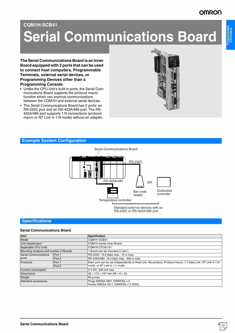
Pro
gra
mm
able
C
on
tro
llers
CQM1H-SCB41
Serial Communications Board
The Serial Communications Board is an Inner Board equipped with 2 ports that can be used to connect host computers, Programmable Terminals, external serial devices, or Programming Devices other than a Programming Console. • Unlike the CPU Unit’s built-in ports, the Serial Com-munications Board supports the protocol macro function which can improve communications between the CQM1H and external serial devices.
• The Serial Communications Board has 2 ports: an RS-232C port and an RS-422A/485 port. The RS-422A/485 port supports 1:N connections (protocol macro or NT Link in 1:N mode) without an adapter.
Serial Communications Board
Example System Configuration
Specifications
Serial Communications Board
Item SpecificationModel CQM1H-SCB41Unit classification CQM1H-series Inner BoardApplicable CPU Units CQM1H-CPU61/51Mounting locations and number of Boards 1 Board can be mounted in slot 1.Serial Communications ports
Port 1 RS-232C: 19.2 kbps max., 15 m max.Port 2 RS-422A/485: 19.2 kbps max., 500 m max.
Protocols Port 1 Each port can be set independently to Host Link, No-protocol, Protocol macro, 1:1 Data Link, NT Link in 1:N mode, or NT Link in 1:1 mode.Port 2
Current consumption 5 V DC, 200 mA max.Dimensions 25 × 110 × 107 mm (W × H × D)Weight 90 g max.Standard accessories Plugs:XM2SA-0901 (OMRON) x 2
Hoods:XM2SA-0911 (OMRON) x 2 (ESD)
Temperature controller
Serial Communications Board
RS-232C
RS-422A/485 OR
Standard external devices with an RS-232C or RS-422A/485 port
Dedicated controller
Bar code reader
43
("1:1:20578")
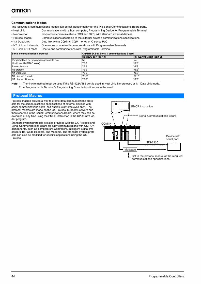
Communications ModesThe following 6 communications modes can be set independently for the two Serial Communications Board ports.• Host Link: Communications with a host computer, Programming Device, or Programmable Terminal• No-protocol: No-protocol communications (TXD and RXD) with standard external devices• Protocol macro: Communications according to the external device’s communications specifications• 1:1 Data Link: Data link with a CQM1H, CQM1, or other C-series PLC• NT Link in 1:N mode: One-to-one or one-to-N communications with Programmable Terminals• NT Link in 1:1 mod: One-to-one communications with Programmable Terminal
Note: 1. The 4-wire method must be used if the RS-422A/485 port is used in Host Link, No-protocol, or 1:1 Data Link mode.2. A Programmable Terminal’s Programming Console function cannot be used.
Protocol MacrosProtocol macros provide a way to create data communications proto-cols for the communications specifications of external devices with serial communications ports (half-duplex, start-stop sync only). The protocol macros are made on the CX-Protocol Support Software and then recorded in the Serial Communications Board, where they can be executed at any time using the PMCR instruction in the CPU Unit’s lad-der program.Standard system protocols are also provided with the CX-Protocol and Serial Communications Board for easy communications with OMRON components, such as Temperature Controllers, Intelligent Signal Pro-cessors, Bar Code Readers, and Modems. The standard system proto-cols can also be modified for specific applications using the CX-Protocol.
Serial communications protocol CQM1H-SCB41 Serial Communications BoardRS-232C port (port 1) RS-422A/485 port (port 2)
Peripheral bus or Programming Console bus No NoHost Link (SYSMAC WAY) YES YES1
Protocol macro YES YESNo-protocol YES YES1
1:1 Data Link YES YES1
NT Link in 1:1 mode YES2 YES2
NT Link in 1:N mode YES2 YES2
CQM1H
RS-232C
PMCR instruction
Serial Communications Board
Message
Device with serial port
Set in the protocol macro for the required communications specifications.
44 Programmable Controllers
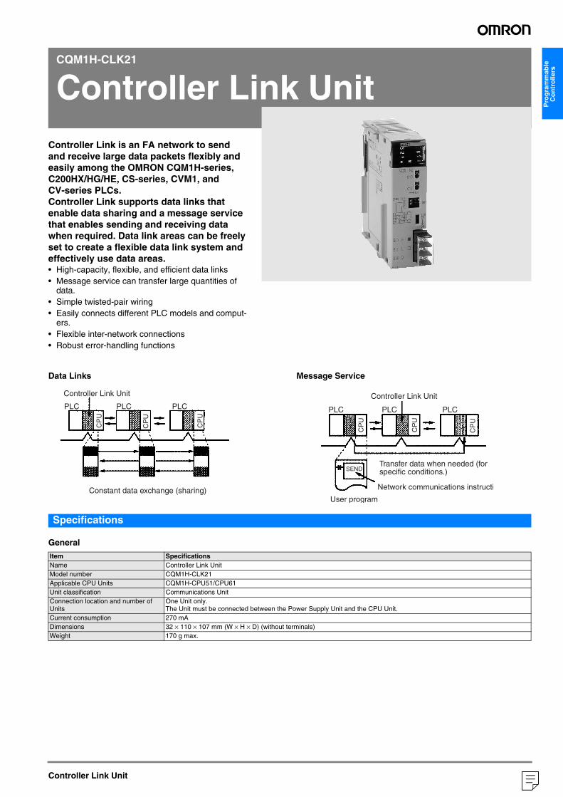
Pro
gra
mm
able
C
on
tro
llers
CQM1H-CLK21
Controller Link Unit
Controller Link is an FA network to send and receive large data packets flexibly and easily among the OMRON CQM1H-series, C200HX/HG/HE, CS-series, CVM1, and CV-series PLCs.Controller Link supports data links that enable data sharing and a message service that enables sending and receiving data when required. Data link areas can be freely set to create a flexible data link system and effectively use data areas.• High-capacity, flexible, and efficient data links• Message service can transfer large quantities ofdata.• Simple twisted-pair wiring• Easily connects different PLC models and comput-
ers.• Flexible inter-network connections• Robust error-handling functions
Controller Link Unit
Data Links Message Service
Specifications
General
Item SpecificationsName Controller Link UnitModel number CQM1H-CLK21Applicable CPU Units CQM1H-CPU51/CPU61Unit classification Communications UnitConnection location and number of Units
One Unit only.The Unit must be connected between the Power Supply Unit and the CPU Unit.
Current consumption 270 mADimensions 32 × 110 × 107 mm (W × H × D) (without terminals)Weight 170 g max.
Controller Link Unit
Constant data exchange (sharing)
Controller Link Unit
Network communications instructi
User program
PLCPLC PLC PLCPLC PLC
SEND
CP
U
CP
U
CP
U
CP
U
CP
U
CP
UTransfer data when needed (for specific conditions.)
45
("1:1:20578")
Communications
Item SpecificationsCommunications method N:N token busCode Manchester codeModulation Baseband codeSynchronization Flag synchronization (conforms to HDLC frames)Transmission path form Multi-drop bus Baud rate and maximum transmission distance
The maximum transmission distance varies with the baud rate as follows:2 Mbps:500 m1 Mbps:800 m500 Kbps:1 km
Media Specified shielded twisted-pair cableNumber of signal lines: 2, shield line: 1
Maximum number of nodes 32 nodesCommunications functions Data links and message service Number of data link words Transmission area per node: 1,000 words max.
Data link area in one CQM1H-series PLC (send/receive): 8,000 words max.Data link areas Bit areas (IR, AR, LR, CIO), data memory (DM), and extended data memory (EM)Message length 2,012 bytes max. (including the header)RAS functions Polling node backup function
Self-diagnosis function (hardware checking at startup)Echoback test and broadcast test (using the FINS command)Watchdog timerError log function
Error control Manchester code checkCRC check (CCITT X16 + X12 + X5 + 1)
46 Programmable Controllers
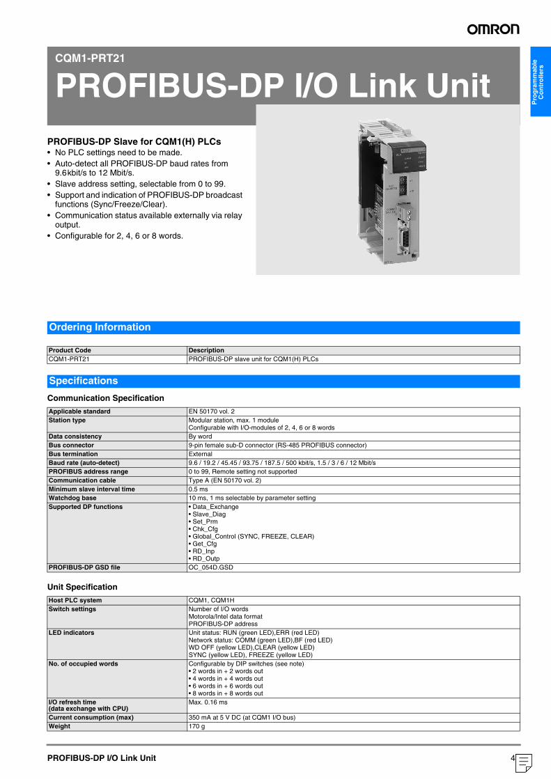
Pro
gra
mm
able
C
on
tro
llers
CQM1-PRT21
PROFIBUS-DP I/O Link Unit
PROFIBUS-DP Slave for CQM1(H) PLCs• No PLC settings need to be made.• Auto-detect all PROFIBUS-DP baud rates from9.6kbit/s to 12 Mbit/s.• Slave address setting, selectable from 0 to 99.• Support and indication of PROFIBUS-DP broadcast
functions (Sync/Freeze/Clear).• Communication status available externally via relay
output.• Configurable for 2, 4, 6 or 8 words.
PROFIBUS-DP I/O Link Unit
Communication Specification
Unit Specification
Ordering Information
Product Code DescriptionCQM1-PRT21 PROFIBUS-DP slave unit for CQM1(H) PLCs
Specifications
Applicable standard EN 50170 vol. 2Station type Modular station, max. 1 module
Configurable with I/O-modules of 2, 4, 6 or 8 wordsData consistency By wordBus connector 9-pin female sub-D connector (RS-485 PROFIBUS connector)Bus termination ExternalBaud rate (auto-detect) 9.6 / 19.2 / 45.45 / 93.75 / 187.5 / 500 kbit/s, 1.5 / 3 / 6 / 12 Mbit/sPROFIBUS address range 0 to 99, Remote setting not supportedCommunication cable Type A (EN 50170 vol. 2)Minimum slave interval time 0.5 msWatchdog base 10 ms, 1 ms selectable by parameter settingSupported DP functions • Data_Exchange
• Slave_Diag• Set_Prm• Chk_Cfg• Global_Control (SYNC, FREEZE, CLEAR)• Get_Cfg• RD_Inp• RD_Outp
PROFIBUS-DP GSD file OC_054D.GSD
Host PLC system CQM1, CQM1HSwitch settings Number of I/O words
Motorola/Intel data formatPROFIBUS-DP address
LED indicators Unit status: RUN (green LED),ERR (red LED)Network status: COMM (green LED),BF (red LED)WD OFF (yellow LED),CLEAR (yellow LED)SYNC (yellow LED), FREEZE (yellow LED)
No. of occupied words Configurable by DIP switches (see note)• 2 words in + 2 words out• 4 words in + 4 words out• 6 words in + 6 words out• 8 words in + 8 words out
I/O refresh time(data exchange with CPU)
Max. 0.16 ms
Current consumption (max) 350 mA at 5 V DC (at CQM1 I/O bus)Weight 170 g
47
("1:1:20578")
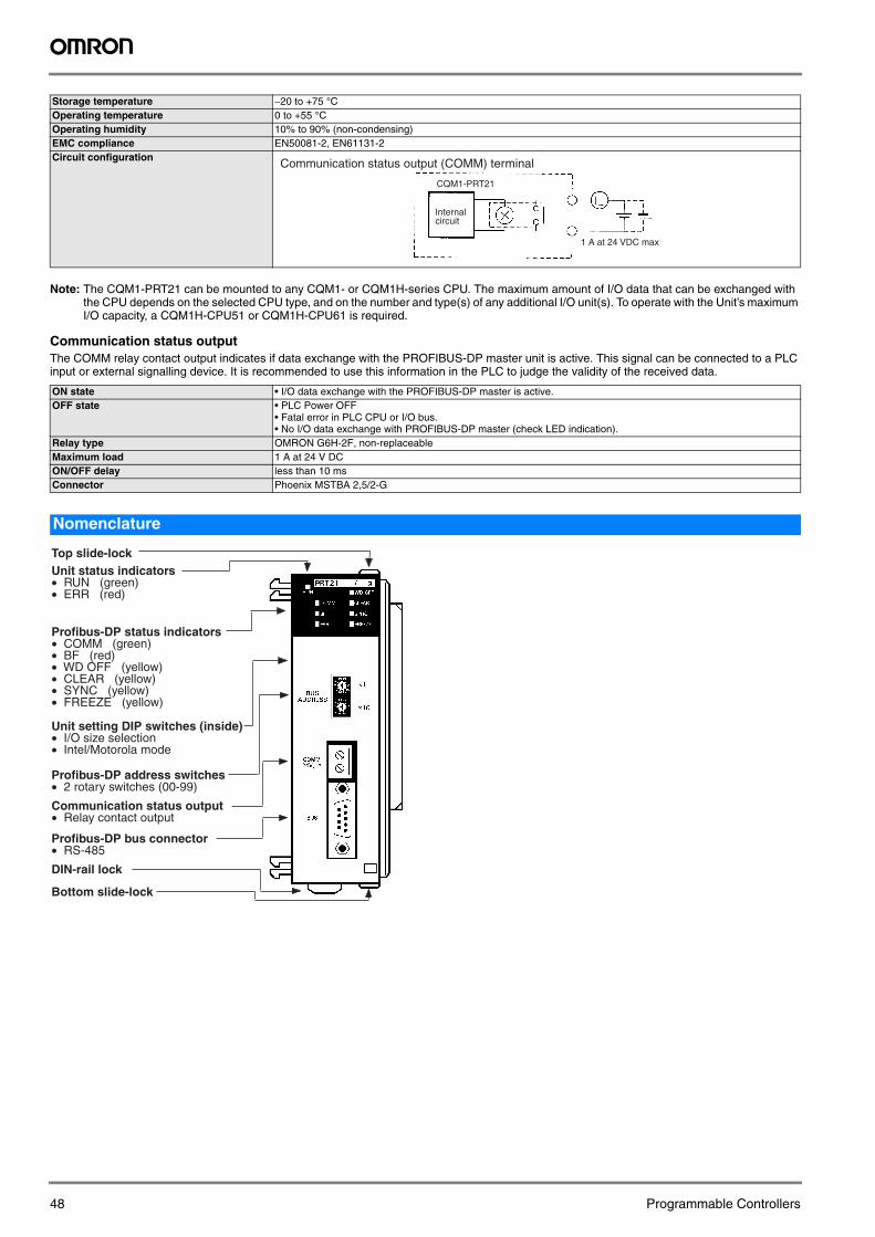
Note: The CQM1-PRT21 can be mounted to any CQM1- or CQM1H-series CPU. The maximum amount of I/O data that can be exchanged with the CPU depends on the selected CPU type, and on the number and type(s) of any additional I/O unit(s). To operate with the Unit’s maximum I/O capacity, a CQM1H-CPU51 or CQM1H-CPU61 is required.
Communication status outputThe COMM relay contact output indicates if data exchange with the PROFIBUS-DP master unit is active. This signal can be connected to a PLC input or external signalling device. It is recommended to use this information in the PLC to judge the validity of the received data.
Storage temperature −20 to +75 °COperating temperature 0 to +55 °COperating humidity 10% to 90% (non-condensing)EMC compliance EN50081-2, EN61131-2Circuit configuration
ON state • I/O data exchange with the PROFIBUS-DP master is active.OFF state • PLC Power OFF
• Fatal error in PLC CPU or I/O bus.• No I/O data exchange with PROFIBUS-DP master (check LED indication).
Relay type OMRON G6H-2F, non-replaceableMaximum load 1 A at 24 V DCON/OFF delay less than 10 msConnector Phoenix MSTBA 2,5/2-G
Nomenclature
1 A at 24 VDC max.
Internal circuit
CQM1-PRT21
Communication status output (COMM) terminal
Top slide-lockUnit status indicators• RUN (green)• ERR (red)
Profibus-DP status indicators• COMM (green)• BF (red)• WD OFF (yellow)• CLEAR (yellow)• SYNC (yellow)• FREEZE (yellow)
Unit setting DIP switches (inside)• I/O size selection• Intel/Motorola mode
Profibus-DP address switches• 2 rotary switches (00-99)
Communication status output• Relay contact output
Profibus-DP bus connector• RS-485
DIN-rail lock
Bottom slide-lock
48 Programmable Controllers
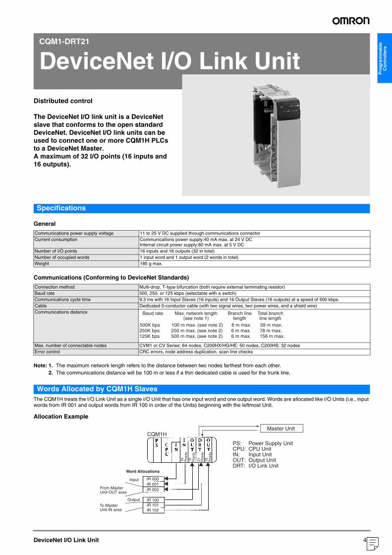
Pro
gra
mm
able
C
on
tro
llers
CQM1-DRT21
DeviceNet I/O Link Unit
Distributed controlThe DeviceNet I/O link unit is a DeviceNet slave that conforms to the open standard DeviceNet. DeviceNet I/O link units can be used to connect one or more CQM1H PLCs to a DeviceNet Master.A maximum of 32 I/O points (16 inputs and 16 outputs).
DeviceNet I/O Link Unit
Specifications
General
Communications (Conforming to DeviceNet Standards)
Note: 1. The maximum network length refers to the distance between two nodes farthest from each other.2. The communications distance will be 100 m or less if a thin dedicated cable is used for the trunk line.
Words Allocated by CQM1H SlavesThe CQM1H treats the I/O Link Unit as a single I/O Unit that has one input word and one output word. Words are allocated like I/O Units (i.e., input words from IR 001 and output words from IR 100 in order of the Units) beginning with the leftmost Unit.
Allocation Example
Communications power supply voltage 11 to 25 V DC supplied through communications connectorCurrent consumption Communications power supply:40 mA max. at 24 V DC
Internal circuit power supply:80 mA max. at 5 V DCNumber of I/O points 16 inputs and 16 outputs (32 in total)Number of occupied words 1 input word and 1 output word (2 words in total)Weight 185 g max.
Connection method Multi-drop, T-type bifurcation (both require external terminating resistor)Baud rate 500, 250, or 125 kbps (selectable with a switch)Communications cycle time 9.3 ms with 16 Input Slaves (16 inputs) and 16 Output Slaves (16 outputs) at a speed of 500 kbps.Cable Dedicated 5-conductor cable (with two signal wires, two power wires, and a shield wire)Communications distance
Max. number of connectable nodes CVM1 or CV Series: 64 nodes, C200HX/HG/HE: 50 nodes, C200HS: 32 nodesError control CRC errors, node address duplication, scan line checks
Baud rate
500K bps 250K bps 125K bps
100 m max. (see note 2) 250 m max. (see note 2) 500 m max. (see note 2)
6 m max. 6 m max. 6 m max.
39 m max. 78 m max. 156 m max.
Max. network length (see note 1)
Branch line length
Total branch line length
CQM1H
IR 000
IR 100
IR 102IR 101
IR 002IR 001
Word Allocations
Input
Master Unit
Output
From Master Unit OUT area
To Master Unit IN area
PS: Power Supply UnitCPU: CPU UnitIN: Input UnitOUT: Output UnitDRT: I/O Link Unit
16
Poi
nts
21
Poi
nts
16
Poi
nts
16
Poi
nts
49
("1:1:20578")
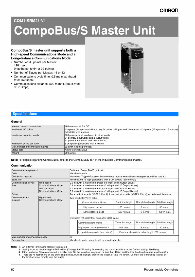
CQM1-SRM21-V1
CompoBus/S Master Unit
CompoBus/S master unit supports both a High-speed Communications Mode and a Long-distance Communications Mode.• Number of I/O points per Master:128 max. (may be set to 64 or 32 points)
• Number of Slaves per Master: 16 or 32• Communications cycle time: 0.5 ms max. (baud
rate: 750 kbps)• Communications distance: 500 m max. (baud rate:
93.75 kbps)
50
Specifications
General
Note: For details regarding CompoBus/S, refer to the CompoBus/S part of the Industrial Communication chapter.
Communication
Note: 1. An external Terminating Resistor is required.2. Setting must be made using the DIP switch. (Change the DM setting for selecting the communications mode. Default setting: 750 kbps)3. If the number of Slaves connected is smaller than 16, the trunk line length can be less than 100 m and the total line length can be less than 50 m.4. There are no restrictions on the branching method, trunk line length, branch line length, or total line length. Connect the terminating resistor on
the location, most remote from the master.
Internal current consumption 180 mA max. at 5 V DCNumber of I/O points 128 points (64 inputs and 64 outputs), 64 points (32 inputs and 32 outputs), or 32 points (16 inputs and 16 outputs)
selectable with a switch.Number of occupied words 128 points:4 input words and 4 output words
64 points:2 input words and 2 output words32 points:1 input word and 1 output word
Number of points per node 8 or 4 points (selectable with a switch)Max. number of connectable Slaves 32 (with 4 points per node)Status data Alarm terminal outputWeight 200 g max.
Communications protocol Dedicated CompoBus/S protocolCode Manchester codeConnection method Multi-drop, T-type bifurcation (both methods require external terminating resistor) (See note 1.)Baud rate 750 kbps, 93.75 kbps (selectable with a DIP switch) (See note 2.)Communications cycle time
High-speed Communications Mode
0.5 ms (with a maximum number of 8 Input and 8 Output Slaves)0.8 ms (with a maximum number of 16 Input and 16 Output Slaves)
Long-distance Communications Mode
4.0 ms (with a maximum number of 8 Input and 8 Output Slaves)6.0 ms (with a maximum number of 16 Input and 16 Output Slaves)
Cable Two-conductor cable (VCTF 0.75 x 2), four-conductor cable (VCTF 0.75 x 4), or dedicated flat cableCommunications distance
High-speed Communications Mode
Max. number of connectable nodes 32Error control Manchester code, frame length, and parity checks
Two-conductor VCTF cable
Trunk line length Branch line length Total line length
100 m max. 3 m max. 50 m max.
Dedicated flat cable/ four-conductor VCTF cable
Communications Mode
High-speed mode
500 m max. 6 m max. 120 m max.Long-distance mode
Trunk line length Branch line length Total line length
30 m max. 3 m max. 30 m max.
Communications Mode
High-speed mode (see note 3)
Free branching (total cable length: 200 m max.) Long-distance mode (see note 4)
Programmable Controllers
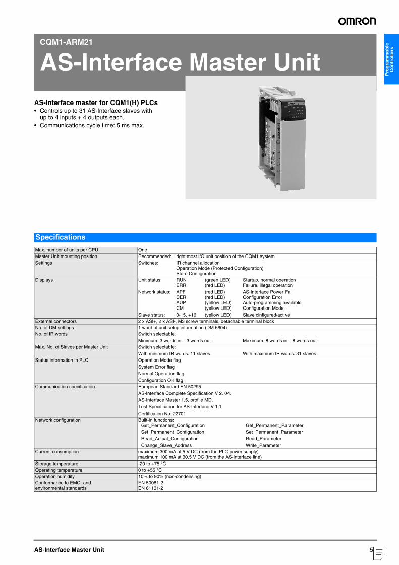
Pro
gra
mm
able
C
on
tro
llers
CQM1-ARM21
AS-Interface Master Unit
AS-Interface master for CQM1(H) PLCs• Controls up to 31 AS-Interface slaves withup to 4 inputs + 4 outputs each.• Communications cycle time: 5 ms max.
AS-Interface Master Unit
Specifications
Max. number of units per CPU OneMaster Unit mounting position Recommended: right most I/O unit position of the CQM1 systemSettings Switches: IR channel allocation
Operation Mode (Protected Configuration)Store Configuration
Displays Unit status: RUN (green LED) Startup, normal operationERR (red LED) Failure, illegal operation
Network status: APF (red LED) AS-Interface Power FallCER (red LED) Configuration ErrorAUP (yellow LED) Auto-programming availableCM (yellow LED) Configuration Mode
Slave status: 0-15, +16 (yellow LED) Slave cinfigured/activeExternal connectors 2 x ASI+, 2 x ASI-, M3 screw terminals, detachable terminal blockNo. of DM settings 1 word of unit setup information (DM 6604)No. of IR words Switch selectable.
Minimum: 3 words in + 3 words out Maximum: 8 words in + 8 words outMax. No. of Slaves per Master Unit Switch selectable:
With minimum IR words: 11 slaves With maximum IR words: 31 slavesStatus information in PLC Operation Mode flag
System Error flagNormal Operation flagConfiguration OK flag
Communication specification European Standard EN 50295AS-Interface Complete Specification V 2. 04.AS-Interface Master 1,5, profile MD.Test Specification for AS-Interface V 1.1Certification No. 22701
Network configuration Built-in functions: Get_Permanent_Configuration Get_Permanent_Parameter Set_Permanent_Configuration Set_Permanent_Parameter Read_Actual_Configuration Read_Parameter Change_Slave_Address Write_Parameter
Current consumption maximum 300 mA at 5 V DC (from the PLC power supply)maximum 100 mA at 30.5 V DC (from the AS-Interface line)
Storage temperature -20 to +75 °COperating temperature 0 to +55 °COperation humidity 10% to 90% (non-condensing)Conformance to EMC- and environmental standards
EN 50081-2EN 61131-2
51
("1:1:20578")
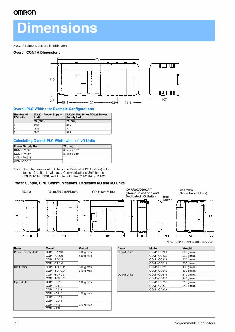
Dimensions
Note: All dimensions are in millimeters.Overall CQM1H Dimensions
Overall PLC Widths for Example Configurations
Calculating Overall PLC Width with “n” I/O Units
Note: The total number of I/O Units and Dedicated I/O Units (n) is lim-ited to 12 Units (11 without a Communications Unit) for the CQM1H-CPU51/61 and 11 Units for the CQM1H-CPU11/21.
Power Supply, CPU, Communications, Dedicated I/O and I/O Units
Number of I/O Units
PA203 Power Supply Unit
PA206, PA216, or PD026 Power Supply Unit
W (mm) W (mm)3 283 3154 315 3475 347 379
Power Supply Unit W (mm)CQM1-PA203 32 × n + 187CQM1-PA206 32 × n + 219CQM1-PA216CQM1-PD026
W
110
53.53.7
120 32 13.5107
PA203 PA206/PA216/PD026 CPU11/21/51/61
*The CQM1-OC224 is 131.7 mm wide.
ID/IA/OC/OD/OA@(Communications and Dedicated I/O Units) End
Cover
Side view(Same for all Units)
Name Model WeightPower Supply Units CQM1-PA203 460 g max
CQM1-PA206 560 g maxCQM1-PD026CQM1-PA216
CPU Units CQM1H-CPU11 500 g max.CQM1H-CPU21 510 g max.CQM1H-CPU51CQM1H-CPU61
Input Units CQM1-ID211 180 g max.CQM1-ID111CQM1-ID212CQM1-ID112 160 g max.CQM1-ID213CQM1-ID214CQM1-IA121 210 g max.CQM1-IA221
Name Model WeightOutput Units CQM1-OC221 200 g max.
CQM1-OC222 230 g max.CQM1-OC224 270 g max.CQM1-OD211 200 g max.CQM1-OD212 180 g max.CQM1-OD213 160 g max.
Output Units CQM1-OD214 210 g max.CQM1-OD215 240 g max.CQM1-OD216 210 g max.CQM1-OA221 240 g max.CQM1-OA222
52 Programmable Controllers
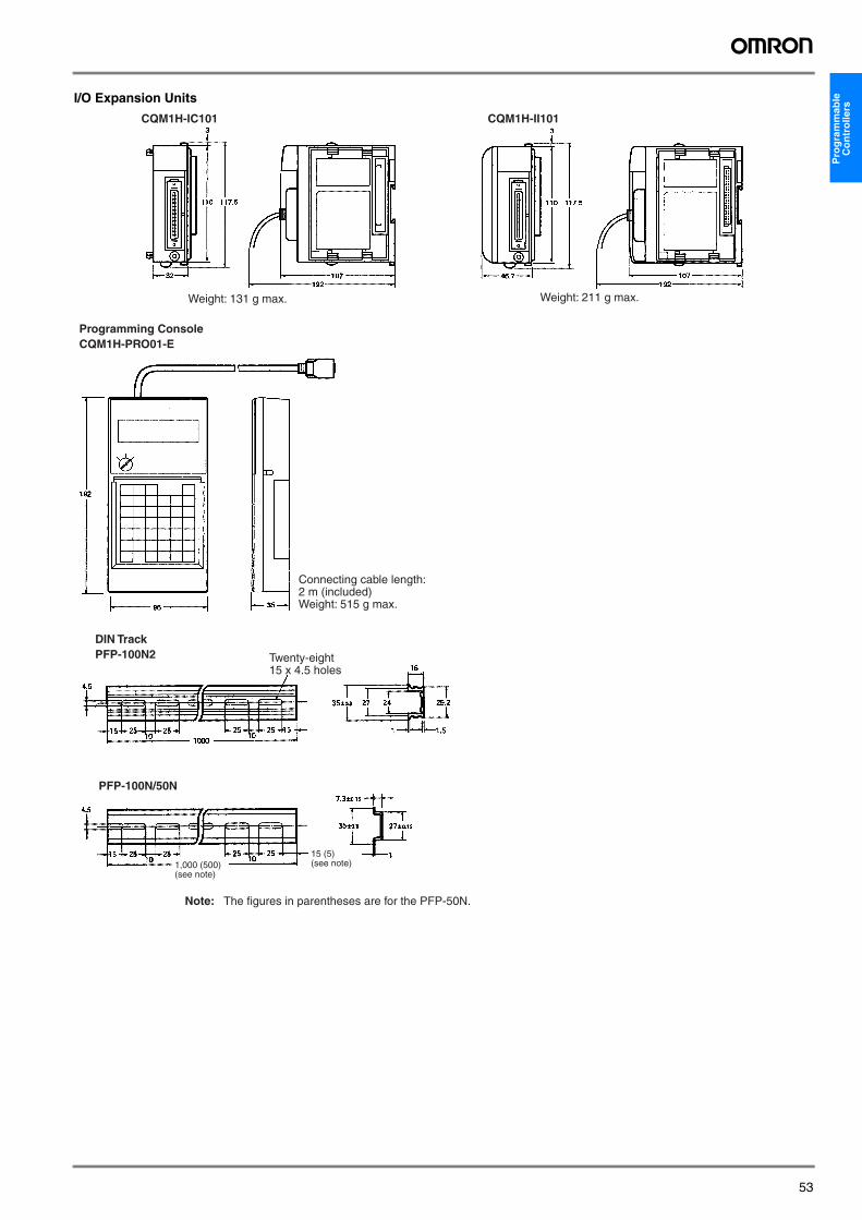
Pro
gra
mm
able
C
on
tro
llers
I/O Expansion Units
CQM1H-IC101 CQM1H-II101
Weight: 131 g max. Weight: 211 g max.
Programming ConsoleCQM1H-PRO01-E
Connecting cable length: 2 m (included)Weight: 515 g max.
PFP-100N/50N
Note: The figures in parentheses are for the PFP-50N.
DIN TrackPFP-100N2 Twenty-eight
15 x 4.5 holes
15 (5) (see note)1,000 (500)
(see note)
53
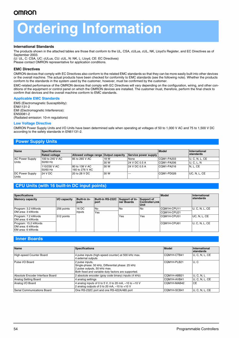
Ordering Information
International StandardsThe products shown in the attached tables are those that conform to the UL, CSA, cULus, cUL, NK, Lloyd’s Register, and EC Directives as of September 2003.(U: UL, C: CSA, UC: cULus, CU: cUL, N: NK, L: Lloyd, CE: EC Directives)Please contact OMRON representative for application conditions.EMC DirectivesOMRON devices that comply with EC Directives also conform to the related EMC standards so that they can be more easily built into other devices or the overall machine. The actual products have been checked for conformity to EMC standards (see the following note). Whether the products conform to the standards in the system used by the customer, however, must be confirmed by the customer.EMC-related performance of the OMRON devices that comply with EC Directives will vary depending on the configuration, wiring, and other con-ditions of the equipment or control panel on which the OMRON devices are installed. The customer must, therefore, perform the final check to confirm that devices and the overall machine conform to EMC standards.
Applicable EMC StandardsEMS (Electromagnetic Susceptibility):EN61131-2EMI (Electromagnetic Interference):EN50081-2 (Radiated emission: 10-m regulations)
Low Voltage DirectiveOMRON Power Supply Units and I/O Units have been determined safe when operating at voltages of 50 to 1,000 V AC and 75 to 1,500 V DC according to the safety standards in EN61131-2.
Power Supply Units
CPU Units (with 16 built-in DC input points)
Inner Boards
Name Specifications Model International standardsRated voltage Allowed voltage range Output capacity Service power supply
AC Power Supply Units
100 to 240 V AC 50/60 Hz
85 to 265 V AC 18 W None CQM1-PA203 U, C, N, L, CE30 W 24 V DC 0.5 A CQM1-PA206 U, C, L, N
110/230 V AC 50/60 Hz
80 to 138 V AC160 to 276 V AC
30 W 24 V DC 0.5 A CQM1-PA216 N, L, CE
DC Power Supply Units
24 V DC 20 to 28 V DC 30 W --- CQM1-PD026 UC, N, L, CE
Specifications Model International standardsMemory capacity I/O capacity Built-in in-
putsBuilt-in RS-232C port
Support of In-ner Boards
Support of Controller Link Unit
Program: 3.2 kWordsDM area: 3 kWords
256 points 16 DC inputs
No No No CQM1H-CPU11 U, C, N, L, CEYes CQM1H-CPU21
Program: 7.2 kWordsDM area: 6 kWords
512 points Yes Yes CQM1H-CPU51 UC, N, L, CE
Program: 15.2 kWordsDM area: 6 kWordsEM area: 6 kWords
CQM1H-CPU61 U, C, N, L, CE
Name Specifications Model International standards
High-speed Counter Board 4 pulse inputs (high-speed counter) at 500 kHz max.4 external outputs
CQM1H-CTB41 U, C, N, L, CE
Pulse I/O Board 2 pulse inputs,Single-phase: 50 kHz, Differential phase: 25 kHz2 pulse outputs, 50 kHz max.Both fixed and variable duty factors are supported.
CQM1H-PLB21 U, C
Absolute Encoder Interface Board 2 absolute encoder (gray code binary) inputs (4 kHz) CQM1H-ABB21 U, C, N, LAnalog Setting Board 4 analog settings CQM1H-AVB41 U, C, N, L, CEAnalog I/O Board 4 analog inputs of 0 to 5 V, 0 to 20 mA, –10 to +10 V
2 analog outputs of 0 to 20 mA, –10 to +10 VCQM1H-MAB42 CE
Serial Communications Board One RS-232C port and one RS-422A/485 port CQM1H-SCB41 U, C, N, L, CE
54 Programmable Controllers
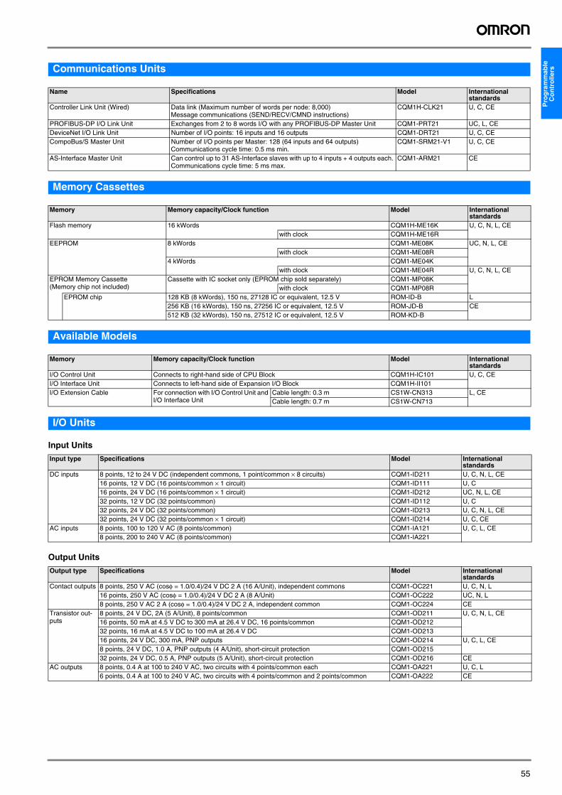
Pro
gra
mm
able
C
on
tro
llers
Communications UnitsMemory Cassettes
Available Models
I/O Units
Input Units
Output Units
Name Specifications Model International standards
Controller Link Unit (Wired) Data link (Maximum number of words per node: 8,000)Message communications (SEND/RECV/CMND instructions)
CQM1H-CLK21 U, C, CE
PROFIBUS-DP I/O Link Unit Exchanges from 2 to 8 words I/O with any PROFIBUS-DP Master Unit CQM1-PRT21 UC, L, CEDeviceNet I/O Link Unit Number of I/O points: 16 inputs and 16 outputs CQM1-DRT21 U, C, CECompoBus/S Master Unit Number of I/O points per Master: 128 (64 inputs and 64 outputs)
Communications cycle time: 0.5 ms min.CQM1-SRM21-V1 U, C, CE
AS-Interface Master Unit Can control up to 31 AS-Interface slaves with up to 4 inputs + 4 outputs each. Communications cycle time: 5 ms max.
CQM1-ARM21 CE
Memory Memory capacity/Clock function Model International standards
Flash memory 16 kWords CQM1H-ME16K U, C, N, L, CEwith clock CQM1H-ME16R
EEPROM 8 kWords CQM1-ME08K UC, N, L, CEwith clock CQM1-ME08R
4 kWords CQM1-ME04Kwith clock CQM1-ME04R U, C, N, L, CE
EPROM Memory Cassette(Memory chip not included)
Cassette with IC socket only (EPROM chip sold separately) CQM1-MP08Kwith clock CQM1-MP08R
EPROM chip 128 KB (8 kWords), 150 ns, 27128 IC or equivalent, 12.5 V ROM-ID-B L256 KB (16 kWords), 150 ns, 27256 IC or equivalent, 12.5 V ROM-JD-B CE512 KB (32 kWords), 150 ns, 27512 IC or equivalent, 12.5 V ROM-KD-B
Memory Memory capacity/Clock function Model International standards
I/O Control Unit Connects to right-hand side of CPU Block CQM1H-IC101 U, C, CEI/O Interface Unit Connects to left-hand side of Expansion I/O Block CQM1H-II101I/O Extension Cable For connection with I/O Control Unit and
I/O Interface UnitCable length: 0.3 m CS1W-CN313 L, CECable length: 0.7 m CS1W-CN713
Input type Specifications Model International standards
DC inputs 8 points, 12 to 24 V DC (independent commons, 1 point/common × 8 circuits) CQM1-ID211 U, C, N, L, CE16 points, 12 V DC (16 points/common × 1 circuit) CQM1-ID111 U, C16 points, 24 V DC (16 points/common × 1 circuit) CQM1-ID212 UC, N, L, CE32 points, 12 V DC (32 points/common) CQM1-ID112 U, C32 points, 24 V DC (32 points/common) CQM1-ID213 U, C, N, L, CE32 points, 24 V DC (32 points/common × 1 circuit) CQM1-ID214 U, C, CE
AC inputs 8 points, 100 to 120 V AC (8 points/common) CQM1-IA121 U, C, L, CE8 points, 200 to 240 V AC (8 points/common) CQM1-IA221
Output type Specifications Model International standards
Contact outputs 8 points, 250 V AC (cosφ = 1.0/0.4)/24 V DC 2 A (16 A/Unit), independent commons CQM1-OC221 U, C, N, L16 points, 250 V AC (cosφ = 1.0/0.4)/24 V DC 2 A (8 A/Unit) CQM1-OC222 UC, N, L8 points, 250 V AC 2 A (cosφ = 1.0/0.4)/24 V DC 2 A, independent common CQM1-OC224 CE
Transistor out-puts
8 points, 24 V DC, 2A (5 A/Unit), 8 points/common CQM1-OD211 U, C, N, L, CE16 points, 50 mA at 4.5 V DC to 300 mA at 26.4 V DC, 16 points/common CQM1-OD21232 points, 16 mA at 4.5 V DC to 100 mA at 26.4 V DC CQM1-OD21316 points, 24 V DC, 300 mA, PNP outputs CQM1-OD214 U, C, L, CE8 points, 24 V DC, 1.0 A, PNP outputs (4 A/Unit), short-circuit protection CQM1-OD21532 points, 24 V DC, 0.5 A, PNP outputs (5 A/Unit), short-circuit protection CQM1-OD216 CE
AC outputs 8 points, 0.4 A at 100 to 240 V AC, two circuits with 4 points/common each CQM1-OA221 U, C, L6 points, 0.4 A at 100 to 240 V AC, two circuits with 4 points/common and 2 points/common CQM1-OA222 CE
55
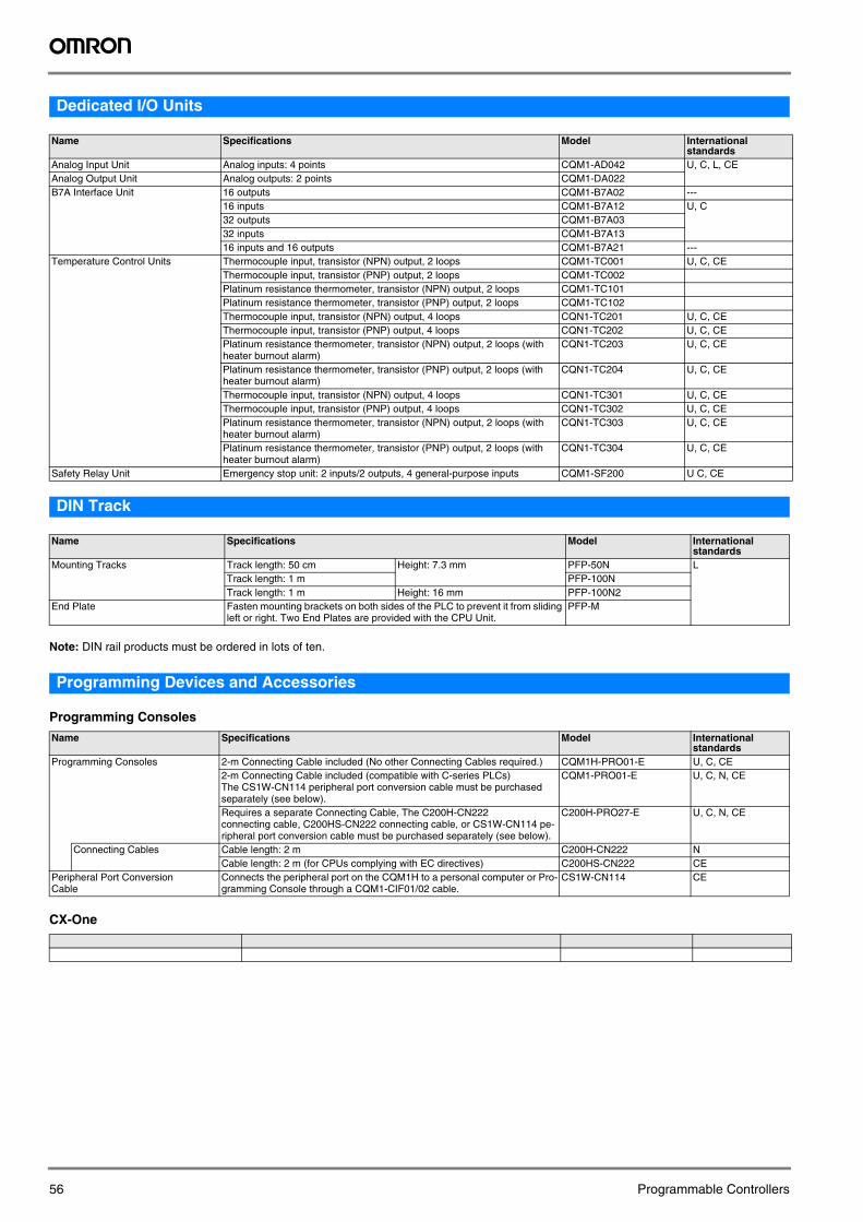
Dedicated I/O Units
DIN Track
Note: DIN rail products must be ordered in lots of ten.
Programming Devices and Accessories
Programming Consoles
CX-One
Name Specifications Model International standards
Analog Input Unit Analog inputs: 4 points CQM1-AD042 U, C, L, CEAnalog Output Unit Analog outputs: 2 points CQM1-DA022B7A Interface Unit 16 outputs CQM1-B7A02 ---
16 inputs CQM1-B7A12 U, C32 outputs CQM1-B7A0332 inputs CQM1-B7A1316 inputs and 16 outputs CQM1-B7A21 ---
Temperature Control Units Thermocouple input, transistor (NPN) output, 2 loops CQM1-TC001 U, C, CEThermocouple input, transistor (PNP) output, 2 loops CQM1-TC002Platinum resistance thermometer, transistor (NPN) output, 2 loops CQM1-TC101Platinum resistance thermometer, transistor (PNP) output, 2 loops CQM1-TC102Thermocouple input, transistor (NPN) output, 4 loops CQN1-TC201 U, C, CEThermocouple input, transistor (PNP) output, 4 loops CQN1-TC202 U, C, CEPlatinum resistance thermometer, transistor (NPN) output, 2 loops (with heater burnout alarm)
CQN1-TC203 U, C, CE
Platinum resistance thermometer, transistor (PNP) output, 2 loops (with heater burnout alarm)
CQN1-TC204 U, C, CE
Thermocouple input, transistor (NPN) output, 4 loops CQN1-TC301 U, C, CEThermocouple input, transistor (PNP) output, 4 loops CQN1-TC302 U, C, CEPlatinum resistance thermometer, transistor (NPN) output, 2 loops (with heater burnout alarm)
CQN1-TC303 U, C, CE
Platinum resistance thermometer, transistor (PNP) output, 2 loops (with heater burnout alarm)
CQN1-TC304 U, C, CE
Safety Relay Unit Emergency stop unit: 2 inputs/2 outputs, 4 general-purpose inputs CQM1-SF200 U C, CE
Name Specifications Model International standards
Mounting Tracks Track length: 50 cm Height: 7.3 mm PFP-50N LTrack length: 1 m PFP-100NTrack length: 1 m Height: 16 mm PFP-100N2
End Plate Fasten mounting brackets on both sides of the PLC to prevent it from sliding left or right. Two End Plates are provided with the CPU Unit.
PFP-M
Name Specifications Model International standards
Programming Consoles 2-m Connecting Cable included (No other Connecting Cables required.) CQM1H-PRO01-E U, C, CE2-m Connecting Cable included (compatible with C-series PLCs)The CS1W-CN114 peripheral port conversion cable must be purchased separately (see below).
CQM1-PRO01-E U, C, N, CE
Requires a separate Connecting Cable, The C200H-CN222 connecting cable, C200HS-CN222 connecting cable, or CS1W-CN114 pe-ripheral port conversion cable must be purchased separately (see below).
C200H-PRO27-E U, C, N, CE
Connecting Cables Cable length: 2 m C200H-CN222 NCable length: 2 m (for CPUs complying with EC directives) C200HS-CN222 CE
Peripheral Port Conversion Cable
Connects the peripheral port on the CQM1H to a personal computer or Pro-gramming Console through a CQM1-CIF01/02 cable.
CS1W-CN114 CE
56 Programmable Controllers
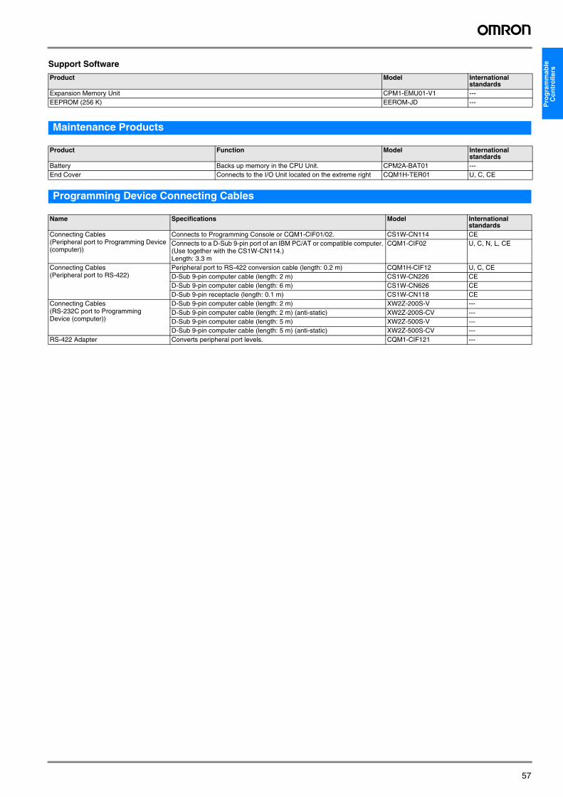
Pro
gra
mm
able
C
on
tro
llers
Support Software
Maintenance Products
Programming Device Connecting Cables
Product Model International standards
Expansion Memory Unit CPM1-EMU01-V1 ---EEPROM (256 K) EEROM-JD ---
Product Function Model International standards
Battery Backs up memory in the CPU Unit. CPM2A-BAT01 ---End Cover Connects to the I/O Unit located on the extreme right CQM1H-TER01 U, C, CE
Name Specifications Model International standards
Connecting Cables(Peripheral port to Programming Device (computer))
Connects to Programming Console or CQM1-CIF01/02. CS1W-CN114 CEConnects to a D-Sub 9-pin port of an IBM PC/AT or compatible computer. (Use together with the CS1W-CN114.)Length: 3.3 m
CQM1-CIF02 U, C, N, L, CE
Connecting Cables(Peripheral port to RS-422)
Peripheral port to RS-422 conversion cable (length: 0.2 m) CQM1H-CIF12 U, C, CED-Sub 9-pin computer cable (length: 2 m) CS1W-CN226 CED-Sub 9-pin computer cable (length: 6 m) CS1W-CN626 CED-Sub 9-pin receptacle (length: 0.1 m) CS1W-CN118 CE
Connecting Cables(RS-232C port to Programming Device (computer))
D-Sub 9-pin computer cable (length: 2 m) XW2Z-200S-V ---D-Sub 9-pin computer cable (length: 2 m) (anti-static) XW2Z-200S-CV ---D-Sub 9-pin computer cable (length: 5 m) XW2Z-500S-V ---D-Sub 9-pin computer cable (length: 5 m) (anti-static) XW2Z-500S-CV ---
RS-422 Adapter Converts peripheral port levels. CQM1-CIF121 ---
57
In the interest of product improvement, specifications are subject to change without notice.
ALL DIMENSIONS SHOWN ARE IN MILLIMETERS.To convert millimeters into inches, multiply by 0.03937. To convert grams into ounces, multiply by 0.03527.
Cat. No. P07E-EN-02
58 Programmable Controllers