SV7110 BMC User Manual - Wiwynn User Manual_V1.1... · 12 Wiwynn SV7110 BMC User Manual 1.3 PWM...
73
SV7110 BMC User Manual Version 1.1 April 2015 Copyright © 2015 Wiwynn. All rights reserved.
Transcript of SV7110 BMC User Manual - Wiwynn User Manual_V1.1... · 12 Wiwynn SV7110 BMC User Manual 1.3 PWM...

SV7110
BMC User Manual
Version 1.1
April 2015
Copyright © 2015 Wiwynn. All rights reserved.
2 Wiwynn SV7110 BMC User Manual
Copyright
Copyright © 2015 by Wiwynn Corporation. All rights reserved. No
part of this publication may be reproduced, transmitted, transcribed,
stored in a retrieval system, or translated into any language or
computer language, in any form or by any means, electronic,
mechanical, magnetic, optical, chemical, manual or otherwise,
without the prior written permission of Wiwynn Corporation.
Disclaimer
The information in this guide is subject to change without notice.
Wiwynn Corporation makes no representations or warranties, either
expressed or implied, with respect to the contents hereof and
specifically disclaims any warranties of merchantability or fitness for
any particular purpose. Any Wiwynn Corporation software described
in this manual is sold or licensed "as is". Should the programs prove
defective following their purchase, the buyer (and not Wiwynn
Corporation, its distributor, or its dealer) assumes the entire cost of
all necessary servicing, repair, and any incidental or consequential
damages resulting from any defect in the software.

Wiwynn SV7110 BMC User Manual 3
Revision History
Date Version Changes
2015/03/19 1.0 First release
2015/04/24 1.1 Revised sections 1.1, 1.6.2 and 2.2
4 Wiwynn SV7110 BMC User Manual
Contents
Preface................................................................................................. 6
Introduction .................................................................................... 6
Audience ........................................................................................ 6
Conventions ................................................................................... 7
Safety Information .......................................................................... 8
1. Hardware Overview ....................................................................... 9
1.1 BMC-related Baseboard Features ..................................... 10
1.2 I2C Ports ............................................................................ 11
1.3 PWM Registers .................................................................. 12
1.4 Fan Speed Reading ........................................................... 12
1.5 Remote Power Control and Power Policy .......................... 12
1.6 Debug Header and UART .................................................. 13
1.7 uServer Management ( Panther+ Card for SV7110) .......... 19
1.8 WatchDog Timer ................................................................ 19
1.9 LEDs driven by BMC ......................................................... 20
1.10 Port 80 POST .................................................................... 20
2. BMC Firmware Functions ........................................................... 21
3. Wiwynn-Specific Extensions ..................................................... 25
3.1 Wiwynn-Specific OEM Commands .................................... 25
4. Network Communications .......................................................... 32
4.1 Management Network Interface ......................................... 32
5. Local Serial Console Redirection and Serial Over LAN........... 33
5.1 Local Serial Console and SoL Features ............................. 33
6. Supported SELs, System Sensors and Thermal Protection ... 35
6.1 System Sensors ................................................................. 35
6.2 System Event Log .............................................................. 46

Wiwynn SV7110 BMC User Manual 5
7. Chassis Cooling Control ............................................................ 72
7.1 Fan Speed Control ............................................................. 72
6 Wiwynn SV7110 BMC User Manual
Preface
Wiwynn SV7110 Baseboard has a BMC for various platform management
services and interfaces with both storage sub-systems on the baseboard and
computing module on the Panther+ card.
Introduction
BMC is a standalone system in parallel to the host (SV7110 baseboard and
Panther+ card). The health status of the host system should not affect the
normal operation and network connectivity of BMC. BMC does not share
memory with the host system. BMC management connectivity should work
independently from the host, and has no NIC driver dependency for
Out-Of-Band communication while using a shared-NIC.
BMC firmware support IPMI 2.0 compliant features and all features must be
remotely accessible. Baseboard Management Controller (BMC) functionality
is based on the SV7110 platform which is designed for storage server with
platform management system.
Audience
This BMC User Manual is for personnel involve in the design, development,
validation, integration, production and support of Wiwynn SV7110 systems. It
is intended for PM (Project Manager), TM (Technical Manager), QT (Quality
Test), Architect, SI (System Integrator) and related team leaders.
Wiwynn SV7110 BMC User Manual 7
Conventions
CAUTION
Indicates the presence of a hazard that may cause minor
personal injury or property damage if the CAUTION is
ignored.
WARNING
Indicates the presence of a hazard that may result in
serious personal injury if the WARNING is ignored.
Commands Commands appear in this font.

8 Wiwynn SV7110 BMC User Manual
Safety Information
WARNING
Before you start using your server product, pay close
attention to all safety instructions.
WARNING
To prevent personal injury or equipment damage from
hazardous electrical conditions that may be present on
power, telephone and communication cables, turn off the
server and disconnect the power cord,
telecommunications systems, networks and other
connected devices before opening the server.
WARNING
Electrostatic discharge (ESD) can damage disk drives,
boards and other parts. It is recommended to perform the
procedures in this chapter in an ESD workstation or
provide some ESD protection by wearing an anti-static
wrist strap to the chassis ground (any unpainted metal
surface) on your server when handling parts.

Wiwynn SV7110 BMC User Manual 9
1. Hardware Overview
ASPEED AST1250 is an Integrated Remote Management Processor (IRMP),
functioning as Baseboard Management Controller (BMC) in the SV7110
Baseboard. It is a vastly integrated SoC device playing as a service
processor to support various functions required for highly manageable server
platforms. Highlighted features are as follows:
Embedded an ARM926EJ 32-bit RISC CPU and a ColdFire V1 CPU
Internal SRAM and external DDR3 ECC SDRAM
Fourteen sets of multi-function I2C/SMBus bus controllers
Five sets of UART I/O interface, four sets with full flow control
Up to 216 GPIO pins
Supports eight PWM outputs, with three types of frequency mode
PWM for fan speed control
Up to sixteen fan tachometer inputs (NCT7904D is used to read fan
speed in SV7110)
Adopt full-scan-chain design methodology for testing internal logic by
Automatic Test Pattern Generation (ATPG)
Supports Built-In-Self-Test (BIST) and JTAG-compliant boundary scan
408 pin, 19mmx19mm TFBGA package, 0.8mm ball pitch
BMC controller with IPMI 2.0/1.5 compliant
LAN: NCSI or SMBUS sideband through Mezzanine card
SPI flash memory
Up to sixteen integrated 10-bit ADCs, low-leakage inputs to measure
voltage rails

10 Wiwynn SV7110 BMC User Manual
Voltage monitor by BMC ADC
SV7110 baseboard uses ADC controller integrated in BMC for voltage
monitor. Voltages are reported as part of the system enclosure status,
and monitored.
1.1 BMC-related Baseboard Features
One BMC is responsible for system enclosure management services,
such as fan control and standard IPMI functions.
Two I2C buses to exchange information between SAS expander and
BMC,
One 10GbE mezzanine card that supports a single 10GbE port
(SFP+).
Shared NIC feature support on the 10GbE mezzanine card for
out-of-band management, by connecting both NCSI/RMII between
10GbE card and BMC.
MAC address for SV7110 system should follow these two rules:
o CX3: each card reserves 3 MAC, port 0, port 1, BMC; BMC
uses port 0 + 2
o Niantic: each card reserves 5 MAC: port 0, port 1, SAN 0, SAN
1, BMC; BMC uses port 0 + 4
One debug header, to accept existing OCP debug card.
POST code from Panther+ card (through FPGA to BMC via I2C
bus), is driven by BMC to a 7-segment display.

Wiwynn SV7110 BMC User Manual 11
The slide switch located beside the debug header on the SV7110
baseboard is used to select POST code or error code to be displayed
on the debug card. Manufacturer’s default setting is POST code.
Two switch buttons:
Power button: If pressed for less than four seconds, a Power
Management Event indicating that the power switch has been
triggered will be issued. If pressed for more than four seconds, the
SV7110 baseboard and Panther+ card will perform a hard power
off.
Reset button: If pressed for any duration of time, the SV7110
baseboard and Panther+ card will perform a hard reset and begin
executing BIOS initialization code.
Status LEDs driven by BMC:
Power and System ID: blue
Fault status: red
1.2 I2C Ports
BMC supports 14 built-in I2C buses to monitor, control, and communicate
with other devices. I2C/SMBus Controller implements one set of global
registers and 14 sets of device registers to program the various functions
supported by AST1250.
12 Wiwynn SV7110 BMC User Manual
1.3 PWM Registers
There are eight built-in PWM registers used by the BMC chip to control the
fans. In the SV7110 design, BMC can support up to six PWM fan regions.
Each region can have a different speed under firmware control and based on
environmental input.
1.4 Fan Speed Reading
AST1250 supports 16 tachometer inputs that are used to measure fan
speeds. For SV7110 Dual Rotor fan support, instead of the tachometer in
AST1250, BMC will use NCT7904D to monitor each dual rotor fan speed for
failover detection, thermal fan curves and acoustic control monitor.
1.5 Remote Power Control and Power Policy
BMC firmware supports remote system power on/off/cycle and warm reboot
through in-band or out-of-band IPMI command. The supported power-on
options are Last-state, Always-on, and Always-off. Default setting is
Last-state.
IPMI command supports change in power policy that takes effect without
having to cold reset the BMC firmware or reboot the system.
It takes BMC around 5 seconds from AC power on to process the power
button signal and power up system for POST. BMC is ready for BIOS SMM
KCS channel communication within 16 seconds.

Wiwynn SV7110 BMC User Manual 13
1.6 Debug Header and UART
The SV7110 baseboard includes a debug header on the front side. It
supports hot plugging for an existing debug card. The card has been used in
Open Compute servers and Open Vault storage with the following functions:
1.6.1 Debug Header
Two 7-segment LED displays showing the firmware POST information
and system error codes.
One RS-232 serial connector
One reset button
One UART channel selection button that sends positive pulse to the
SV7110 Baseboard to select and rotate UART console in a loop of:
Host console -> BMC debug console -> SAS controller console ->
SAS expander console.
Default baud rate of all channels is 57600 bps.
Default user name and password are sysadmin and superuser.

14 Wiwynn SV7110 BMC User Manual
1.6.2 Debug Code Selection
The debug card displays a two-digit debug code that can be one of these
two:
POST code from Panther+ card
Error code from Expander and BMC
Use the slide switch located beside the baseboard debug card connector to
select which debug code to be displayed on the SV7110 debug card.
Manufacturer’s default setting is POST code.

Wiwynn SV7110 BMC User Manual 15
1.6.3 Error Code Definition
Error Code Description
0 No error
1 Reserved
2 Reserved
3 I2C bus A crash
4 I2C bus B crash
5 I2C bus C crash
6 I2C bus D crash
8 Reserved
9 Reserved
10 Reserved
11 Fan 1 front fault
12 Fan 1 rear fault
13 Fan 2 front fault
14 Fan 2 rear fault
15 Fan 3 front fault
16 Fan 3 rear fault
17 Fan 4 front fault
18 Fan 4 rear fault
19 Fan 5 front fault
20 Fan 5 rear fault
21 Fan 6 front fault
22 Fan 6 rear fault
23 Reserved
24 Reserved
25 PPC CPU temp. critical
26 PPC DIMM A0 temp. critical
27 PPC DIMM A1 temp. critical
28 PPC DIMM B0 temp. critical

16 Wiwynn SV7110 BMC User Manual
Error Code Description
29 PPC DIMM B1 temp. critical
30 PPC ambient temp. critical
31 DPB temp. 1 critical
32 DPB temp. 2 critical
33 DPB temp. 3 critical
34 DPB temp. 4 critical
35 FCB BJT temp. 1 critical
36 FCB BJT temp. 2 critical
37 HBB SAS ctrl. temp. critical
38 HBB expander temp. critical
39 HBB ambient temp. critical
40 Reserved
41 Reserved
42 Reserved
43 PPC voltage critical
44 HBB voltage critical
45 DPB voltage critical
46 FCB voltage critical
47 PPC current critical
48 HBB current critical
49 FCB current critical
50 HDD0 SMART temp critical
51 HDD1 SMART temp critical
52 HDD2 SMART temp critical
53 HDD3 SMART temp critical
54 HDD4 SMART temp critical
55 HDD5 SMART temp critical
56 HDD6 SMART temp critical
57 HDD7 SMART temp critical
58 HDD8 SMART temp critical

Wiwynn SV7110 BMC User Manual 17
Error Code Description
59 HDD9 SMART temp critical
60 HDD10 SMART temp critical
61 HDD11 SMART temp critical
62 HDD12 SMART temp critical
63 HDD13 SMART temp critical
64 HDD14 SMART temp critical
65 Reserved
66 Reserved
67 Reserved
68 Reserved
69 Reserved
70 HDD0 fault
71 HDD1 fault
72 HDD2 fault
73 HDD3 fault
74 HDD4 fault
75 HDD5 fault
76 HDD6 fault
77 HDD7 fault
78 HDD8 fault
79 HDD9 fault
80 HDD10 fault
81 HDD11 fault
82 HDD12 fault
83 HDD13 fault
84 HDD14 fault
85 Reserved
86 Reserved
87 Reserved
88 Reserved

18 Wiwynn SV7110 BMC User Manual
Error Code Description
89 Reserved
90 External Mini-SAS Link Error
91 Internal Mini-SAS Link Error
92 Reserved
93 Self Tray Pulled-out
94 Peer Tray Pulled-out
95 Reserved
96 Reserved
97 Reserved
98 Reserved
99 Firmware and Hardware Mismatch
C2 Correctable Machine Check Error
C3 CPU IERR
C4 Thermal Trip
C5 Bus Correctable Error
C6 Bus Uncorrectable Error
C7 Bus Fatal Error
C8 Memory Hot
CA Uncorrectable ECC
CD VR Hot
CE Processor hot

Wiwynn SV7110 BMC User Manual 19
1.7 uServer Management ( Panther+ Card
for SV7110)
The FPGA on the Panther+ card works as a management interface with the
Intel Atom SoC and provides I2C bus interface to the BMC on the SV7110
baseboard.
This FPGA implements the following peripherals on the local Host/CPU side:
Two IPMI KCS interfaces (SMM and SMS) as defined in the IPMI
specification
At least one standard 16550 (mapped as COM1/0x3f8 to the host)
GPIOs for controlling host functions and obtaining status (e.g.
processor presence, voltage domain presence, power control, host
reset, etc.)
I2C Proxy interfaces for control and status (e.g. obtaining DIMM and
CPU temperatures)
POST code buffer to hold BIOS/POST progress (mapped as port 80h
to the host)
1.8 WatchDog Timer
Watch Dog Timer (WDT) is designed to prevent system deadlock. In general,
WDT must be restarted when it reaches timeout.
20 Wiwynn SV7110 BMC User Manual
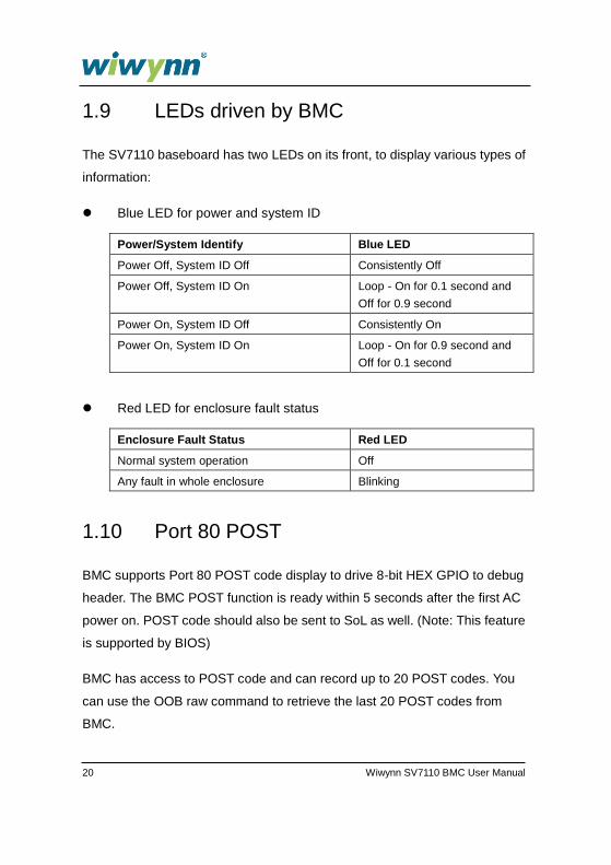
1.9 LEDs driven by BMC
The SV7110 baseboard has two LEDs on its front, to display various types of
information:
Blue LED for power and system ID
Power/System Identify Blue LED
Power Off, System ID Off Consistently Off
Power Off, System ID On Loop - On for 0.1 second and
Off for 0.9 second
Power On, System ID Off Consistently On
Power On, System ID On Loop - On for 0.9 second and
Off for 0.1 second
Red LED for enclosure fault status
Enclosure Fault Status Red LED
Normal system operation Off
Any fault in whole enclosure Blinking
1.10 Port 80 POST
BMC supports Port 80 POST code display to drive 8-bit HEX GPIO to debug
header. The BMC POST function is ready within 5 seconds after the first AC
power on. POST code should also be sent to SoL as well. (Note: This feature
is supported by BIOS)
BMC has access to POST code and can record up to 20 POST codes. You
can use the OOB raw command to retrieve the last 20 POST codes from
BMC.

Wiwynn SV7110 BMC User Manual 21
2. BMC Firmware Functions
2.1 BMC Features Overview
Support shared-NIC through NCSI or SMBUS sideband
Support Local serial console and SOL.
Support for I2C interfaces
WatchDog support
SMBus 2.0 support
IPMI 2.0 compliance
Read Log events
Sensor monitoring
FAN speed control
IPMI based user management
Multiple user permission level
Support for remotely power-cycle, power-down, power-up, reset the
server
Flash Utility-YAFU Flash: IPMI based firmware update
IPMI command through KCS
System reset
BIOS Port 80 post code to seven-segment LED display
Power and System Identification LED
Sensors [Analog sensors, Discrete sensors, Event only sensors]
Firmware update for BMC and FPGA

22 Wiwynn SV7110 BMC User Manual
2.2 Firmware Update
2.2.1 BMC Firmware Update
BMC can implement remote BMC firmware update without requiring any
physical input on the system. Remote update can be through Out-Of-Band
by management network or through logging into local OS (CentOS) by data
network. The BMC firmware update tool(s) support CentOS 5.2.
The following steps show the alternate BMC firmware update by USB:
1 Add this ipmitool command to enable virtual device (default is disable):
ipmitool raw 0x32 0xaa 0x00
2 Key in
./Yafuflash -cd rom.ima (at local OS).
Wait for the flash process to finish and BMC will restart automatically.
A remote BMC firmware update may take a maximum of 5 minutes to
complete. BMC firmware update and BMC reset processes do not require
rebooting or powering down of the host system and have no impact on
normal operation of host system. Wiwynn BMC is fully functional after
firmware update and reset without requiring further configuration.
BMC supports dual images for fail-over function.
Normally, BCM always boots from image 1. If image 1 is damaged, u-boot
selects image 2 to boot. After the user updates image 1, u-boot selects
image 1 to boot again.

Wiwynn SV7110 BMC User Manual 23
2.2.2 FPGA Code Update
BMC can implement remote FPGA code update without requiring any
physical input on the system. Remote update can be through Out-Of-Band
by management network or through logging into local OS (CentOS) by data
network. The BMC firmware update tool(s) support CentOS 5.2.
The following steps show the alternate FPGA code update by USB:
1 Add this ipmitool command to enable virtual device (default is disable):
ipmitool raw 0x32 0xaa 0x00
2 Key in
./Yafuflash -cd -cpld fpga.bin (at local OS)
Wait for the flash process to finish and BMC will restart automatically.
2.2.3 Remote BIOS Recovery via OOB
BMC implements BIOS recovery mechanism through OOB. You can use this
command to perform BIOS recovery:
1 Key in
./Yafuflash -u USERID -p PASSW0RD -nw -ip 192.168.0.100
-d 2 ~/AMI.iso0

24 Wiwynn SV7110 BMC User Manual
After issuing this command, BIOS recovery mechanism starts automatically.
The limitations are as follows:
1 BIOS boot section should be alive.
2 The image should be in ISO format. BMC will not check if the image is
correct or not.
2.3 Sync Sensor Reading between BMC and
Expander with IPMB
The Expander periodically synchronizes the temperature, voltage, current,
and fan speed sensor reading with BMC via IPMB over I2C bus. There are
two pairs of I2C buses used for communicating sensor synchronization
between Expander and BMC.
2.4 Hardware Monitoring Sensors in Expander
Overview
The Expander firmware automatically monitors the fans via hardware monitor
chip and voltages, temperature, and current sensors.
The expander firmware periodically synchronizes most of those sensors with
BMC via IPMB protocol over I2C bus.

Wiwynn SV7110 BMC User Manual 25
3. Wiwynn-Specific Extensions
Wiwynn BMC will implement some OEM commands and parameters in order
to support Wiwynn-specific features that are not defined in the IPMI
specification. The goal is to keep this list to a minimum.
3.1 Wiwynn-Specific OEM Commands
The following table lists all the OEM commands and OEM extensions to
standard IPMI commands that the BMC supports.
3.1.1 Retrieve Last 20x POST Codes
This command retrieves the last 20x POST codes from BMC.
Table 1. OEM command format to retrieve POST code
NetFn/LUN 1 30/00
Cmd 2 10
Request Data 3:5 00 2B 99 Wiwynn Manufacturer ID, LS Byte first
6 01 Function Code
Response Data 1 Completion Code
2 Post Code 1
3 Post Code 2
… …
21 Post Code 20

26 Wiwynn SV7110 BMC User Manual
3.1.2 Specify Average Window for Each Host-BMC Power Query
This OEM command specifies the average window for each host-BMC power
query; while the BMC should query ADM1178 regularly at a fix interval.
The fixed interval is 1 second for SV7110 BMC. This means that BMC will
query ADM1178 once every second.
For example, if the OEM command specifies the average of ten 1-second
windows, the BMC should report the average power of the last 10 readings to
the host.
Table 2. Average power query OEM command format
NetFn/LUN 1 30/00
Cmd 2 21
Request Data 3:5 00 2B 99 Wiwynn Manufacturer ID, LS Byte first
6 Specify average window (second)
Response
Data
1 Completion Code
2 Specify average window(second) return setting value for
double check
3.1.3 Retrieve Serial Console Buffer
This command can retrieve last 5x screens of local and 5x screens of remote
console output, 80 columns x 24 rows for each screen. Use text editor
(notepad.txt) open combuffer.txt can display last 5x screen contents.
Wiwynn SV7110 BMC User Manual 27
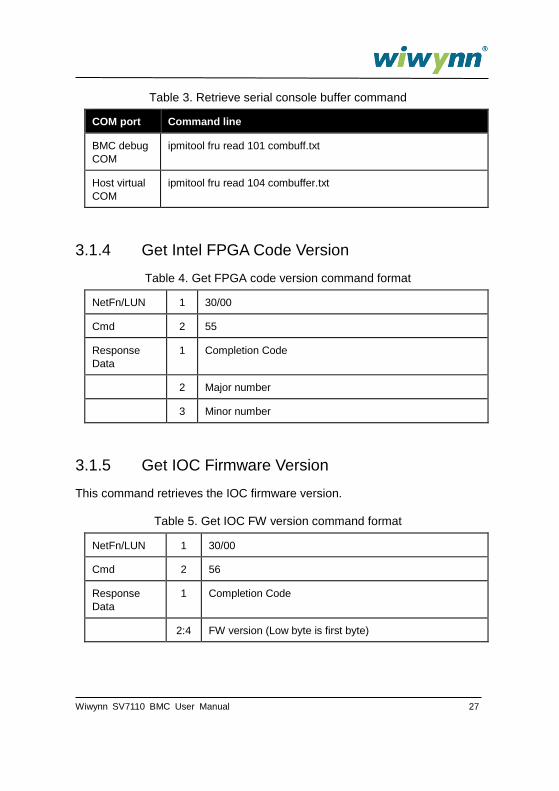
Table 3. Retrieve serial console buffer command
COM port Command line
BMC debug
COM
ipmitool fru read 101 combuff.txt
Host virtual
COM
ipmitool fru read 104 combuffer.txt
3.1.4 Get Intel FPGA Code Version
Table 4. Get FPGA code version command format
NetFn/LUN 1 30/00
Cmd 2 55
Response
Data
1 Completion Code
2 Major number
3 Minor number
3.1.5 Get IOC Firmware Version
This command retrieves the IOC firmware version.
Table 5. Get IOC FW version command format
NetFn/LUN 1 30/00
Cmd 2 56
Response
Data
1 Completion Code
2:4 FW version (Low byte is first byte)

28 Wiwynn SV7110 BMC User Manual
3.1.6 Get Expander Firmware Version
This command retrieves the Expander firmware version.
Table 6. Get Expander firmware version command format
NetFn/LUN 1 30/00
Cmd 2 56
Response
Data
1 Completion Code
2:4 FW version (Low byte is first byte)
3.1.7 Set NTP Configuration
This command sets the NTP configuration.
Table 7. Set NTP configuration command format
NetFn/LUN 1 32/00
Cmd 2 A8
Request
Data
3 1-Primary
Server IP
2-Secondary
Server IP
3-Enable /
Disable NTP
4:131 Primary Server
IP
Secondary
Server IP
1- Enable /
0-Disable
Response
Data
1 Completion Code:
00h = success
cch = Invalid Data Field
c1h = Invalid Command
c7h = Invalid Data Length
ffh = Unspecified Error

Wiwynn SV7110 BMC User Manual 29
3.1.8 Get NTP Configuration
This command retrieves the NTP configuration.
Table 8. Get NTP configuration command format
NetFn/LUN 1 32/00
Cmd 2 A7
Response
Data
1 Completion Code:
00h = success
cch = Invalid Data Field
c1h = Invalid Command
c7h = Invalid Data Length
ffh = Unspecified Error
2 Enable/Disable Status of NTP
3:130 Primary Server IP, MSB first
131:258 Secondary Server IP, MSB first
3.1.9 Get IPv6 LAN Configuration
This command retrieves the IPv6 LAN configuration.
Table 9. Get IPv6 LAN configuration command format
NetFn/LUN 1 0C/00
Cmd 2 02
Request Data 3 [7] - 0b = get parameter
1b = get parameter revision only.
[6:4] - reserved
[3:0] - Channel number.
4 Parameter selector (greater than 192 is OEM index)
5 Set Selector. Selects a given set of parameters under a
given Parameter selector value (00h if parameter does
not use a Set Selector).

30 Wiwynn SV7110 BMC User Manual
6 Block Selector (00h if parameter does not require a
block number)
Response
Data
1 Completion Code
2 [7:0] - Parameter revision.
3:N Configuration parameter data
3.1.10 Set IPv6 LAN Configuration
This command sets the IPv6 LAN configuration.
Table 10. Set IPv6 LAN configuration command format
NetFn/LUN 1 0C/00
Cmd 2 01
Request Data 3 [7:4] - reserved
[3:0] - Channel number.
4 Parameter selector (bigger than 192 is OEM index)
5:N Configuration parameter data
Response
Data
1 Completion Code

Wiwynn SV7110 BMC User Manual 31
3.1.11 AMI LAN Configuration OEM Parameter
Table 11. LAN configuration OEM parameter
Parameter # Parameter data
IPv6 IP
Address
source
196 Data 1 - Address source
0h = unspecified
1h = static address
2h = DHCP
IPv6 IP
Address
197 While Setting:
Data 1 - Index value (0x01 for 10G interface in
SV7110)
Data 2:17 - 16 bytes of IPv6 address. MS-byte first.
While Getting:
Data 1:16 - 16 bytes of IPv6 address. MS-byte first.
Prefix
Length
198 While Setting:
Data 1 - Index value (0x01 for 10G interface in
SV7110)
Data 2 - Prefix length should be from 0 to 128 as
per IPv6 spec.
While Getting:
Data 1 - Prefix length.
IPv6 Default
Gateway
199 Data 1:16 - 16 bytes IPv6 gateway address. MS-byte
first.
32 Wiwynn SV7110 BMC User Manual
4. Network Communications
4.1 Management Network Interface
BMC is designed to support both SMBUS sideband port and RMII/NCSI port
for Out-Of-Band access.
BMC firmware is flexible about which interface and device to activate by
hardware strapping or a preset priority policy (now set to NCSI only). BMC
firmware needs to make sure that unused interfaces and devices are
disabled and do not interfere with the activated management interface and
device.
BMC management network firmware and utility support all features defined in
this specification in both IPv4 and IPv6 network environment.
4.2 Management Network Interface Features
BMC out-of-band access: I2C port
BMC Out-Of-Band access- RMII/NCSI port
BMC management network firmware and utility support all features
defined in this specification in both IPv4 and IPv6 network
environments.
BMC firmware needs to be flexible about which interface and device to
activate by hardware strapping or a preset priority policy.
BMC firmware needs to make sure that unused interfaces and devices
are disabled and do not interfere with the activated management
interface and device.
Wiwynn SV7110 BMC User Manual 33
5. Local Serial Console Redirection and Serial Over LAN
Wiwynn BMC is designed to support two paths for accessing the serial
console. Both interfaces are functional at all stages of system operation.
A local serial console on debug header / debug card, as described in
this specification.
A remote console, also known as Serial-over-LAN (SoL) through
management network described in section 4.1.
5.1 Local Serial Console and SoL Features
Requires a serial console buffer feature
A buffer needs to save at least last 5x local screens and 5x remote
console output screens with a resolution of 80 columns x 24 rows for
each screen.
Use OOB raw command to extract and display the buffer.
Store buffer in volatile media such as the BMC’s internal or external
SDRAM. Buffer data is cleared within 5 seconds upon removal of
standby power. Buffer should NOT be stored in any non-volatile media.
During system boot, POST codes are sent to Port 80 and decoded by
BMC to drive the LED display on debug card. POST codes should be
displayed in the SoL console during system POST.

34 Wiwynn SV7110 BMC User Manual
Before the system has the first screen, POST codes are dumped to
and displayed in the SoL console in sequence. After the system has
the first screen in SoL console, the last POST code received on Port 80
is displayed on the lower right corner of the SoL console screen.
BMC controls the switching of console input and output between SoL
and Local on the fly. In case of legacy limitation wherein only one
interface is functional, the default is set to Local.
When UART console switch is changed to channel 01, BMC is able to
identify this action and switches the console back to Local to re-enable
local console access.
BMC needs to support two paths to access the serial console (Local
and SoL). A local serial console on the debug header and a remote
console, also known as Serial-over-LAN (SoL) that works through
management network. It is preferred that both interfaces are functional
at all stages of system operation.

Wiwynn SV7110 BMC User Manual 35
6. Supported SELs, System Sensors and Thermal Protection
6.1 System Sensors
BMC has access to all analog sensors, discrete sensors and event-only
sensors on the SV7110 baseboard and Panther+ card (through I2C
management interface from FPGA). All connected sensors are displayed in
the sensor data record (SDR) repository.
The following table shows the supported sensors. Note that the lower and
upper critical thresholds are listed for system event logging purpose.
6.1.1 Discrete Sensors
Table 12. Discrete Sensors
Sensor No. 1
Name Processor (CPU Status)
Entity ID 03h
SDR/Type 02h
Sensor Type Processor
Sensor Type
Codes
07h
Sensor Reading
Type
6Fh
Assertion 00h-IERR
01h-Thermal Trip
02h-FRB1/BIST failure
03h-FRB2/Hang in POST failure
04h-FRB3/Processor Startup/Initialization failure (CPU didn’t start)
05h-Configuration Error
06h-SM BIOS ‘Uncorrectable CPU-complex Error’
07h-Processor Presence detected

36 Wiwynn SV7110 BMC User Manual
08h-Processor disabled
09h-Terminator Presence Detected
0Ah-Processor Automatically Throttled
0Bh-Machine Check ERR
0Ch-Correctable Machine Check Error
Sensor No. 2
Name System FW
Entity ID 22h
SDR/Type 02h
Sensor Type System Firmware Progress
Sensor Type
Codes
0fh
Sensor Reading
Type
6Fh
Assertion System Firmware Error (POST Error):
01h- No system memory is physically installed in the system.
02h- No usable system memory, all installed memory has experienced
an unrecoverable failure.
03h- Unrecoverable hard-disk/ATAPI/IDE device failure.
07h- Unrecoverable PS/2 or USB keyboard failure.
08h- Removable boot media not found.
0Ah- No video device detected.
0Bh- Firmware (BIOS) ROM corruption detected.
Sensor No. 3
Name CPU ERR
Entity ID 03h
SDR/Type 02h
Sensor Type Critical Interrupt
Sensor Type
Codes
13h
Sensor No. 5
Name DIMM A0 Correctable ECC
Entity ID 20h
SDR/Type 02h
Sensor Type Memory
Sensor Type 0Ch
Wiwynn SV7110 BMC User Manual 37
Codes
Sensor No. 6
Name DIMM B0 Correctable ECC
Entity ID 20h
SDR/Type 02h
Sensor Type Memory
Sensor Type
Codes
0Ch
Sensor No. 7
Name DIMM A1 Correctable ECC
Entity ID 20h
SDR/Type 02h
Sensor Type Memory
Sensor Type
Codes
0Ch
Sensor No. 8
Name DIMM B1 Correctable ECC
Entity ID 20h
SDR/Type 02h
Sensor Type Memory
Sensor Type
Codes
0Ch
Sensor No. 9
Name Memory
Entity ID 20h
SDR/Type 02h
Sensor Type Memory
Sensor Type
Codes
0Ch
Sensor Reading
Type
6Fh
Assertion 00h-Correctable ECC
01h-Uncorrectable ECC
02h-Parity

38 Wiwynn SV7110 BMC User Manual
03h-Memory Scrub Failed
04h-Memory Device Disabled
05h-Correctable ECC / other correctable memory error logging limit
reached
Sensor No. 13
Name Event Log
Entity ID 21h
SDR/Type 2
Sensor Type Event Logging Disabled
Sensor Type
Codes
10h
Sensor Reading
Type
0Fh
Assertion 02h – Log Area Reset/Cleared
04h – SEL Full
05h – SEL Almost Full
Sensor No. 14
Name Watchdog2
Entity ID 21h
SDR/Type 2
Sensor Type Watchdog 2
Sensor Type
Codes
23h
Sensor Reading
Type
6Fh
Assertion 00h – Timer Expired
01h – Hard Reset
02h – Power Down
03h – Power Cycle
08h – Timer Interrupt
Sensor No. 206
Name System Event
Entity ID 22h
SDR/Type 2
Sensor Type System Event
Wiwynn SV7110 BMC User Manual 39
Sensor Type
Codes
12h
Sensor Reading
Type
6Fh
Assertion 00h – System Reconfigured00h – System Reconfigured
01h –OEM System Boot Event
02h – Undetermined System hardware fail
03h – Entry added to Auxiliary Log
04h – PEF Action
05h – Timestamp Clock Synch
Sensor No. 210
Name VR HOT
Entity ID
SDR/Type 2
Sensor Type OEM
Sensor Type
Codes
c0h
Sensor Reading
Type
6Fh
Sensor No. 211
Name Temp Alert
Entity ID
SDR/Type 2
Sensor Type OEM
Sensor Type
Codes
c0h
Sensor Reading
Type
6Fh
Assertion
Sensor No. 212
Name PCIE
Entity ID 24h
SDR/Type 2
Sensor Type Critical Interrupt
Sensor Type 13h

40 Wiwynn SV7110 BMC User Manual
Codes
Sensor Reading
Type
6Fh
Assertion
6.1.2 Analog Sensors
Table 13. Analog Sensors for Fan
Sensor
No.
Name Entity
ID
SDR/
Type
Sensor
Type
Sensor
Type
Codes
Sensor
Reading
Type
LNC UNC
21 Fan 1
Front
1Dh 01h Fan 04h 01h 1500.000 13000.000
22 Fan 1
Rear 1Dh 01h Fan 04h 01h 1300.000 12000.000
23 Fan 2
Front 1Dh 01h Fan 04h 01h 1500.000 13000.000
24 Fan 2
Rear 1Dh 01h Fan 04h 01h 1300.000 12000.000
25 Fan 3
Front 1Dh 01h Fan 04h 01h 1500.000 13000.000
26 Fan 3
Rear 1Dh 01h Fan 04h 01h 1300.000 12000.000
27 Fan 4
Front 1Dh 01h Fan 04h 01h 1500.000 13000.000
28 Fan 4
Rear 1Dh 01h Fan 04h 01h 1300.000 12000.000
29 Fan 5
Front 1Dh 01h Fan 04h 01h 1500.000 13000.000
30 Fan 5
Rear 1Dh 01h Fan 04h 01h 1300.000 12000.000
31 Fan 6
Front 1Dh 01h Fan 04h 01h 1500.000 13000.000
32 Fan 6
Rear 1Dh 01h Fan 04h 01h 1300.000 12000.000

Wiwynn SV7110 BMC User Manual 41
Table 14. Analog Sensors for FCB
Sensor
No.
Name Entity
ID
SDR/
Type
Sensor
Type
Sensor
Type
Codes
Sensor
Reading
Type
LNC UNC
52 FCB Voltage
12.5V_1 0ah 01h Voltage 02h 01h 11.220 13.740
53 FCB Voltage
12.5V_2 0ah 01h Voltage 02h 01h 11.220 13.740
54 FCB Voltage
12.5V_3 0ah 01h Voltage 02h 01h 11.220 13.740
55 FCB Voltage
3.3V 0ah 01h Voltage 02h 01h 2.960 3.620
56 FCB Current 0ah 01h Current 03h 01h NA 59.920
57 FCB Power 0ah 01h Power
Supply 08h 01h 0.000
1020.00
0
Table 15. Analog Sensors for PPC
Sensor
No.
Name Entity
ID
SDR/
Type
Sensor
Type
Sensor
Type
Codes
Sensor
Reading
Type
LNC UNC
200 PPC Board
Temp 10h 01h
Temper
ature 01h 01h 0.000 75.000
58 PPC Voltage
VCCP 10h 01h Voltage 02h 01h 0.510 1.303
59 PPC Voltage
VNN 10h 01h Voltage 02h 01h 0.510 1.303
60 PPC Voltage
1.0V 10h 01h Voltage 02h 01h 0.902 1.107
61 PPC Voltage
1.35V 10h 01h Voltage 02h 01h 1.215 1.490
62 PPC Voltage
1.8V 10h 01h Voltage 02h 01h 1.627 1.989
63 PPC Voltage
12.5V 10h 01h Voltage 02h 01h 11.286 13.770
64 PPC Voltage
3.3V_MAIN 10h 01h Voltage 02h 01h 2.940 3.646
65 PPC Voltage
3.3V_STBY 10h 01h Voltage 02h 01h 2.940 3.646
202 PPC Current 10h 01h Current 03h 01h NA 5.610

42 Wiwynn SV7110 BMC User Manual
90 PPC CPU
Temp 06h 01h
Temper
ature 01h 01h 0.000 90.000
91 PPC DIMM
A0 Temp 20h 01h
Temper
ature 01h 01h 0.000 82.000
92 PPC DIMM
A1 Temp 20h 01h
Temper
ature 01h 01h 0.000 82.000
93 PPC DIMM
B0 Temp 20h 01h
Temper
ature 01h 01h 0.000 82.000
94 PPC DIMM
B1 Temp 20h 01h
Temper
ature 01h 01h 0.000 82.000
Table 16. Analog Sensors for DPB
Sensor
No.
Name Entity
ID
SDR/
Type
Sensor
Type
Sensor
Type
Codes
Sensor
Reading
Type
LNC UNC
75 DPB Voltage
5V_1 0Fh 01h Voltage 02h 01h 4.480 5.440
76 DPB Voltage
5V_2 0Fh 01h Voltage 02h 01h 4.480 5.440
77 DPB Voltage
5V_3 0Fh 01h Voltage 02h 01h 4.480 5.440
78 DPB Voltage
12.5V 0Fh 01h Voltage 02h 01h 11.232 13.728
79 DPB Temp 1 0Fh 01h Temper
ature 01h 01h 0.000 55.000
80 DPB Temp 2 0Fh 01h Temper
ature 01h 01h 0.000 55.000
81 DPB Temp 3 0Fh 01h Temper
ature 01h 01h 0.000 55.000
82 DPB Temp 4 0Fh 01h Temper
ature 01h 01h 0.000 55.000

Wiwynn SV7110 BMC User Manual 43
Table 17. Analog Sensors for SV7110 Board
Sensor
No.
Name Entity
ID
SDR/
Type
Sensor
Type
Sensor
Type
Codes
Sensor
Reading
Type
LNC UNC
66 HBB Voltage
12.5V 07h 01h Voltage 02h 01h 11.264 13.760
67 HBB Voltage
5V_STBY 07h 01h Voltage 02h 01h 4.536 5.502
68 HBB Voltage
3.3V_STBY 07h 01h Voltage 02h 01h 2.984 3.647
69 HBB Voltage
1.8V_STBY 07h 01h Voltage 02h 01h 1.630 1.989
70 HBB Voltage
1.5V 07h 01h Voltage 02h 01h 1.358 1.659
71 HBB Voltage
0.9V_CTRL 07h 01h Voltage 02h 01h 0.863 1.057
72 HBB Voltage
0.9V_EXP 07h 01h
Voltage 02h 01h 0.815 0.999
74 HBB Current 07h 02h Current 03h 01h NA 8.160
240 HBB Voltage
1.5EXP 07h 01h Voltage 02h 01h 1.358 1.659
83
HBB
Ambient
Temp
07h 01h Temper
ature 01h 01h 0.000 50.000
84
HBB
Expander
Temp
09h 01h Temper
ature 01h 01h 0.000 95.000
85 HBB IOC
Temp 09h 01h
Temper
ature 01h 01h 0.000 95.000
215 System Out
Temp 21h 01h
Temper
ature 01h 01h 0.000 75.000
151 Mezz Amb
Temp 07h 01h
Temper
ature 01h 01h 0.000 60.000
152
IOC
Ambient
Temp
07h 01h Temper
ature 01h 01h 0.000 70.000
153 ExpanderA
mb Temp 07h 01h
Temper
ature 01h 01h 0.000 70.000

44 Wiwynn SV7110 BMC User Manual
Table 18. Analog Sensors for FCB
Sensor
No.
Name Entity
ID
SDR/
Type
Sensor
Type
Sensor
Type
Codes
Sensor
Reading
Type
LNC UNC
87 BJT Temp.
Sensor 1 0ah 01h
Temper
ature 01h 01h 0.000 55.000
88 BJT Temp.
Sensor 2 0ah 01h
Temper
ature 01h 01h 0.000 55.000
Table 19. Analog Sensors for Power
Sensor
No.
Name Entity
ID
SDR/
Type
Sensor
Type
Sensor
Type
Codes
Sensor
Reading
Type
LNC UNC
119 PPC Watt 15h 01h Power
Supply 02h 01h NA 32.385
120 HBB PWR 15h 01h Power
Supply 02h 01h NA 64.770
Table 20. Analog Sensors for DPB HDD
Sensor
No.
Name Entity
ID
SDR/
Type
Sensor
Type
Sensor
Type
Codes
Sensor
Reading
Type
LNC UNC
100
HDD
SMART
Temp. 00
04h 01h Drive
Slot 0Dh 01h 5.000 65.000
101
HDD
SMART
Temp. 01
04h 01h Drive
Slot 0Dh 01h 5.000 65.000
102
HDD
SMART
Temp. 02
04h 01h Drive
Slot 0Dh 01h 5.000 65.000
103
HDD
SMART
Temp. 03
04h 01h Drive
Slot 0Dh 01h 5.000 65.000
104
HDD
SMART
Temp. 04
04h 01h Drive
Slot 0Dh 01h 5.000 65.000
105
HDD
SMART
Temp. 05
04h 01h Drive
Slot 0Dh 01h 5.000 65.000

Wiwynn SV7110 BMC User Manual 45
106
HDD
SMART
Temp. 06
04h 01h Drive
Slot 0Dh 01h 5.000 65.000
107
HDD
SMART
Temp. 07
04h 01h Drive
Slot 0Dh 01h 5.000 65.000
108
HDD
SMART
Temp. 08
04h 01h Drive
Slot 0Dh 01h 5.000 65.000
109
HDD
SMART
Temp. 09
04h 01h Drive
Slot 0Dh 01h 5.000 65.000
110
HDD
SMART
Temp. 10
04h 01h Drive
Slot 0Dh 01h 5.000 65.000
111
HDD
SMART
Temp. 11
04h 01h Drive
Slot 0Dh 01h 5.000 65.000
112
HDD
SMART
Temp. 12
04h 01h Drive
Slot 0Dh 01h 5.000 65.000
113
HDD
SMART
Temp. 13
04h 01h Drive
Slot 0Dh 01h 5.000 65.000
114
HDD
SMART
Temp. 14
04h 01h Drive
Slot 0Dh 01h 5.000 65.000

46 Wiwynn SV7110 BMC User Manual
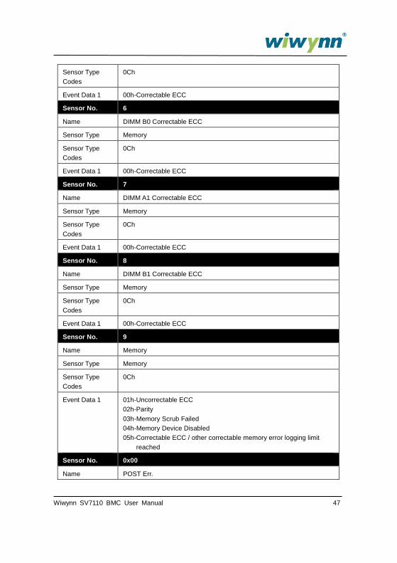
6.2 System Event Log
Table 21. Supported System Event Log (SEL)
Sensor No. 1
Name Processor (CPU Status)
Sensor Type Processor
Sensor Type
Codes
07h
Event Data 1 00h-IERR
01h-Thermal Trip
02h-FRB1/BIST failure
03h-FRB2/Hang in POST failure
04h-FRB3/Processor Startup/Initialization failure (CPU didn’t start)
05h-Configuration Error
06h-SM BIOS ‘Uncorrectable CPU-complex Error’
07h-Processor Presence detected
08h-Processor disabled
09h-Terminator Presence Detected
0Ah-Processor Automatically Throttled
0Bh-Machine Check ERR
0Ch-Correctable Machine Check Error
Sensor No. 2
Name SystemFW
Sensor Type System Firmware Progress
Sensor Type
Codes
0Fh
Event Data 1 System Firmware Error (POST Error):
01h No system memory is physically installed in the system.
02h No usable system memory, all installed memory has
experienced an unrecoverable failure.
03h Unrecoverable hard-disk/ATAPI/IDE device failure.
07h Unrecoverable PS/2 or USB keyboard failure.
08h Removable boot media not found
0Ah No video device detected
0Bh Firmware (BIOS) ROM corruption detected
Sensor No. 5
Name DIMM A0 Correctable ECC
Sensor Type Memory
Wiwynn SV7110 BMC User Manual 47
Sensor Type
Codes
0Ch
Event Data 1 00h-Correctable ECC
Sensor No. 6
Name DIMM B0 Correctable ECC
Sensor Type Memory
Sensor Type
Codes
0Ch
Event Data 1 00h-Correctable ECC
Sensor No. 7
Name DIMM A1 Correctable ECC
Sensor Type Memory
Sensor Type
Codes
0Ch
Event Data 1 00h-Correctable ECC
Sensor No. 8
Name DIMM B1 Correctable ECC
Sensor Type Memory
Sensor Type
Codes
0Ch
Event Data 1 00h-Correctable ECC
Sensor No. 9
Name Memory
Sensor Type Memory
Sensor Type
Codes
0Ch
Event Data 1 01h-Uncorrectable ECC
02h-Parity
03h-Memory Scrub Failed
04h-Memory Device Disabled
05h-Correctable ECC / other correctable memory error logging limit
reached
Sensor No. 0x00
Name POST Err.

48 Wiwynn SV7110 BMC User Manual
Sensor Type System Firmware Progress
Sensor Type
Codes
0x0f
Event Data 1 [7:6]= 10b, LSB of POST Error Code or 11b, Per IPMI Spec
[5:4]=10b
[3:0]=00b,Firmware Error
Event Data 2 If ED1[7:6]=11b, ED2[7:0]=
01h, No system memory is physically installed in the system
02h, No usable system memory
03h, Unrecoverable hard-disk/ATAPI/IDE device failure
07h, Unrecoverable PS/2 or USB keyboard failure
08h, Removable boot media not found
0Bh, Firmware (BIOS) ROM corruption detected
Sensor No. 0x01
Name Machine Chk Err
Sensor Type Processor
Sensor Type
Codes
0x07
Event Data 1 [7:6]=10b
[5:4]=10b
[3:0]=0Bh, Uncorrectable
Or 0Ch, Correctable
Event Data 2 Error Code ID
0x00= Bus Interface Unit
0x01= Bus Interface Unit
0x02= Level-2 shared 1-MB Cache
0x03= Memory Execution Cluster
0x04= Front-End Cluster, includes the Instruction Cache
0x05= SoC System Agent
Event Data 3 [7:5] CPU #
[4:3] Source
00b = check Error Code ID
01b = LLC
[2:0], if LLC, Core #
Sensor No. 13
Name Event Log

Wiwynn SV7110 BMC User Manual 49
Sensor Type Event Logging Disabled
Sensor Type
Codes
10h
Event Data 1 02h – Log Area Reset/Cleared
04h – SEL Full
05h – SEL Almost Full
Sensor No. 14
Name Watchdog2
Sensor Type Watchdog 2
Sensor Type
Codes
23h
Event Data 1 00h – Timer Expired
01h – Hard Reset
02h – Power Down
03h – Power Cycle
08h – Timer Interrupt
Event Data 2 [7:4] interrupt type
0h = none
1h = SMI
2h = NMI
3h = Messaging Interrupt
Fh = unspecified
all other = reserved
[3:0] timer use at expiration:
0h = reserved
1h = BIOS FRB2
2h = BIOS/POST
3h = OS Load
4h = SMS/OS
5h = OEM
Fh = unspecified
Sensor No. 206
Name System Event
Sensor Type System Event
Sensor Type
Codes
12h

50 Wiwynn SV7110 BMC User Manual
Event Data 1 00h – System Reconfigured
01h –OEM System Boot Event
02h – Undetermined System hardware fail
03h – Entry added to Auxiliary Log
04h – PEF Action
05h – Timestamp Clock Synch
Sensor No. 210
Name VR_HOT
Sensor Type OEM
Sensor Type
Codes
c0h
Event Data 1 00h-VRhot
Sensor No. 211
Name Temp_Alert
Sensor Type OEM
Sensor Type
Codes
c0h
Event Data 1 00h-OEM Temp Alert
Event Data 2 N/A
Event Data 3 N/A
Sensor No. 212
Name PCIE
Sensor Type Critical Interrupt
Sensor Type
Codes
13h
Event Data 1 07h-Bus Correctable Error
08h-Bus Uncorrectable Error
09h-Fatal NMI (port 61h, bit 7)
0Ah-Bus Fatal Error
Event Data 2 [2:0] Function #
[7:3] Device #
Event Data 3 [7:0] Bus #
Sensor No. 21
Name Fan 1 Front

Wiwynn SV7110 BMC User Manual 51
Sensor Type Fan
Sensor Type
Codes
04h
Event Data 1 [7:6] - 01b = trigger reading in byte 2
Event Data 2 Reading that triggered event
Event Data 3 Threshold value that triggered event
Sensor No. 22
Name Fan 1 Rear
Sensor Type Fan
Sensor Type
Codes
04h
Event Data 1 [7:6] - 01b = trigger reading in byte 2
Event Data 2 Reading that triggered event
Event Data 3 Threshold value that triggered event
Sensor No. 23
Name Fan 2 Front
Sensor Type Fan
Sensor Type
Codes
04h
Event Data 1 [7:6] - 01b = trigger reading in byte 2
Event Data 2 Reading that triggered event
Event Data 3 Threshold value that triggered event
Sensor No. 24
Name Fan 2 Rear
Sensor Type Fan
Sensor Type
Codes
04h
Event Data 1 [7:6] - 01b = trigger reading in byte 2
Event Data 2 Reading that triggered event
Event Data 3 Threshold value that triggered event
Sensor No. 25
Name Fan 3 Front
Sensor Type Fan

52 Wiwynn SV7110 BMC User Manual
Sensor Type
Codes
04h
Event Data 1 [7:6] - 01b = trigger reading in byte 2
Event Data 2 Reading that triggered event
Event Data 3 Threshold value that triggered event
Sensor No. 26
Name Fan 3 Rear
Sensor Type Fan
Sensor Type
Codes
04h
Event Data 1 [7:6] - 01b = trigger reading in byte 2
Event Data 2 Reading that triggered event
Event Data 3 Threshold value that triggered event
Sensor No. 27
Name Fan 4 Front
Sensor Type Fan
Sensor Type
Codes
04h
Event Data 1 [7:6] - 01b = trigger reading in byte 2
Event Data 2 Reading that triggered event
Event Data 3 Threshold value that triggered event
Sensor No. 28
Name Fan 4 Rear
Sensor Type Fan
Sensor Type
Codes
04h
Event Data 1 [7:6] - 01b = trigger reading in byte 2
Event Data 2 Reading that triggered event
Event Data 3 Threshold value that triggered event
Sensor No. 29
Name Fan 5 Front
Sensor Type Fan
Sensor Type 04h

Wiwynn SV7110 BMC User Manual 53
Codes
Event Data 1 [7:6] - 01b = trigger reading in byte 2
Event Data 2 Reading that triggered event
Event Data 3 Threshold value that triggered event
Sensor No. 30
Name Fan 5 Rear
Sensor Type Fan
Sensor Type
Codes
04h
Event Data 1 [7:6] - 01b = trigger reading in byte 2
Event Data 2 Reading that triggered event
Event Data 3 Threshold value that triggered event
Sensor No. 31
Name Fan 6 Front
Sensor Type Fan
Sensor Type
Codes
04h
Event Data 1 [7:6] - 01b = trigger reading in byte 2
Event Data 2 Reading that triggered event
Event Data 3 Threshold value that triggered event
Sensor No. 32
Name Fan 6 Rear
Sensor Type Fan
Sensor Type
Codes
04h
Event Data 1 [7:6] - 01b = trigger reading in byte 2
Event Data 2 Reading that triggered event
Event Data 3 Threshold value that triggered event
Sensor No. 52
Name FCB Voltage 12.5V_1
Sensor Type Voltage
Sensor Type
Codes
02h

54 Wiwynn SV7110 BMC User Manual
Event Data 1 [7:6] - 01b = trigger reading in byte 2
Event Data 2 Reading that triggered event
Event Data 3 Threshold value that triggered event
Sensor No. 53
Name FCB Voltage 12.5V_2
Sensor Type Voltage
Sensor Type
Codes
02h
Event Data 1 [7:6] - 01b = trigger reading in byte 2
Event Data 2 Reading that triggered event
Event Data 3 Threshold value that triggered event
Sensor No. 54
Name FCB Voltage 12.5V_3
Sensor Type Voltage
Sensor Type
Codes
02h
Event Data 1 [7:6] - 01b = trigger reading in byte 2
Event Data 2 Reading that triggered event
Event Data 3 Threshold value that triggered event
Sensor No. 55
Name FCB Voltage 3.3V
Sensor Type Voltage
Sensor Type
Codes
02h
Event Data 1 [7:6] - 01b = trigger reading in byte 2
Event Data 2 Reading that triggered event
Event Data 3 Threshold value that triggered event
Sensor No. 56
Name FCB Current
Sensor Type Current
Sensor Type
Codes
03h
Event Data 1 [7:6] - 01b = trigger reading in byte 2

Wiwynn SV7110 BMC User Manual 55
Event Data 2 Reading that triggered event
Event Data 3 Threshold value that triggered event
Sensor No. 57
Name FCB Power
Sensor Type Power Supply
Sensor Type
Codes
02h
Event Data 1 [7:6] - 01b = trigger reading in byte 2
Event Data 2 Reading that triggered event
Event Data 3 Threshold value that triggered event
Sensor No. 200
Name PPC Ambient Temp
Sensor Type Temperature
Sensor Type
Codes
01h
Event Data 1 [7:6] - 01b = trigger reading in byte 2
Event Data 2 Reading that triggered event
Event Data 3 Threshold value that triggered event
Sensor No. 58
Name PPC Voltage VCCP
Sensor Type Voltage
Sensor Type
Codes
02h
Event Data 1 [7:6] - 01b = trigger reading in byte 2
Event Data 2 Reading that triggered event
Event Data 3 Threshold value that triggered event
Sensor No. 59
Name PPC Voltage VNN
Sensor Type Voltage
Sensor Type
Codes
02h
Event Data 1 [7:6] - 01b = trigger reading in byte 2
Event Data 2 Reading that triggered event

56 Wiwynn SV7110 BMC User Manual
Event Data 3 Threshold value that triggered event
Sensor No. 60
Name PPC Voltage 1.0V
Sensor Type Voltage
Sensor Type
Codes
02h
Event Data 1 [7:6] - 01b = trigger reading in byte 2
Event Data 2 Reading that triggered event
Event Data 3 Threshold value that triggered event
Sensor No. 61
Name PPC Voltage 1.35V
Sensor Type Voltage
Sensor Type
Codes
02h
Event Data 1 [7:6] - 01b = trigger reading in byte 2
Event Data 2 Reading that triggered event
Event Data 3 Threshold value that triggered event
Sensor No. 62
Name PPC Voltage 1.8V
Sensor Type Voltage
Sensor Type
Codes
02h
Event Data 1 [7:6] - 01b = trigger reading in byte 2
Event Data 2 Reading that triggered event
Event Data 3 Threshold value that triggered event
Sensor No. 63
Name PPC Voltage 12.5V
Sensor Type Voltage
Sensor Type
Codes
02h
Event Data 1 [7:6] - 01b = trigger reading in byte 2
Event Data 2 Reading that triggered event
Event Data 3 Threshold value that triggered event

Wiwynn SV7110 BMC User Manual 57
Sensor No. 64
Name PPC Voltage 3.3V_MAIN
Sensor Type Voltage
Sensor Type
Codes
02h
Event Data 1 [7:6] - 01b = trigger reading in byte 2
Event Data 2 Reading that triggered event
Event Data 3 Threshold value that triggered event
Sensor No. 65
Name PPC Voltage 3.3V_STBY
Sensor Type Voltage
Sensor Type
Codes
02h
Event Data 1 [7:6] - 01b = trigger reading in byte 2
Event Data 2 Reading that triggered event
Event Data 3 Threshold value that triggered event
Sensor No. 202
Name PPC Current
Sensor Type Current
Sensor Type
Codes
03h
Event Data 1 [7:6] - 01b = trigger reading in byte 2
Event Data 2 Reading that triggered event
Event Data 3 Threshold value that triggered event
Sensor No. 90
Name PPC CPU Temp. Sensor
Sensor Type Temperature
Sensor Type
Codes
01h
Event Data 1 [7:6] - 01b = trigger reading in byte 2
Event Data 2 Reading that triggered event
Event Data 3 Threshold value that triggered event
Sensor No. 91

58 Wiwynn SV7110 BMC User Manual
Name PPC DIMM A0 Temp. Sensor
Sensor Type Temperature
Sensor Type
Codes
01h
Event Data 1 [7:6] - 01b = trigger reading in byte 2
Event Data 2 Reading that triggered event
Event Data 3 Threshold value that triggered event
Sensor No. 92
Name PPC DIMM A1 Temp. Sensor
Sensor Type Temperature
Sensor Type
Codes
01h
Event Data 1 [7:6] - 01b = trigger reading in byte 2
Event Data 2 Reading that triggered event
Event Data 3 Threshold value that triggered event
Sensor No. 93
Name PPC DIMM B0 Temp. Sensor
Sensor Type Temperature
Sensor Type
Codes
01h
Event Data 1 [7:6] - 01b = trigger reading in byte 2
Event Data 2 Reading that triggered event
Event Data 3 Threshold value that triggered event
Sensor No. 94
Name PPC DIMM B1 Temp. Sensor
Sensor Type Temperature
Sensor Type
Codes
01h
Event Data 1 [7:6] - 01b = trigger reading in byte 2
Event Data 2 Reading that triggered event
Event Data 3 Threshold value that triggered event
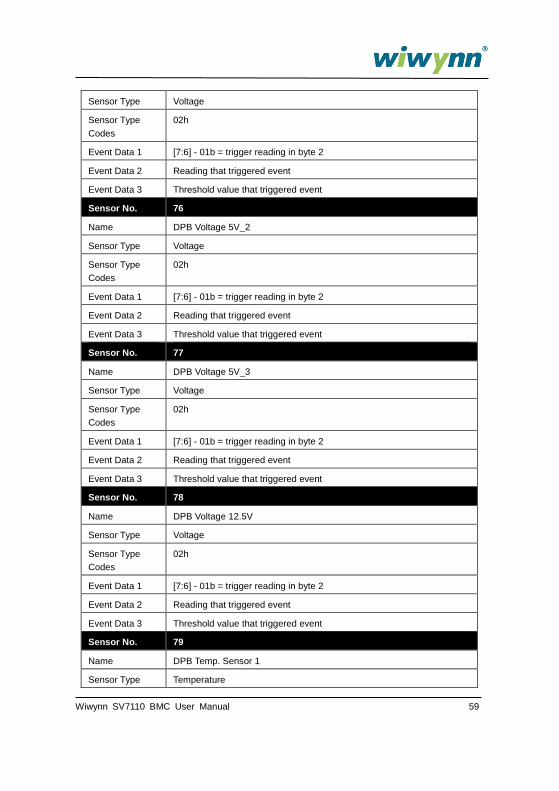
Sensor No. 75
Name DPB Voltage 5V_1
Wiwynn SV7110 BMC User Manual 59
Sensor Type Voltage
Sensor Type
Codes
02h
Event Data 1 [7:6] - 01b = trigger reading in byte 2
Event Data 2 Reading that triggered event
Event Data 3 Threshold value that triggered event
Sensor No. 76
Name DPB Voltage 5V_2
Sensor Type Voltage
Sensor Type
Codes
02h
Event Data 1 [7:6] - 01b = trigger reading in byte 2
Event Data 2 Reading that triggered event
Event Data 3 Threshold value that triggered event
Sensor No. 77
Name DPB Voltage 5V_3
Sensor Type Voltage
Sensor Type
Codes
02h
Event Data 1 [7:6] - 01b = trigger reading in byte 2
Event Data 2 Reading that triggered event
Event Data 3 Threshold value that triggered event
Sensor No. 78
Name DPB Voltage 12.5V
Sensor Type Voltage
Sensor Type
Codes
02h
Event Data 1 [7:6] - 01b = trigger reading in byte 2
Event Data 2 Reading that triggered event
Event Data 3 Threshold value that triggered event
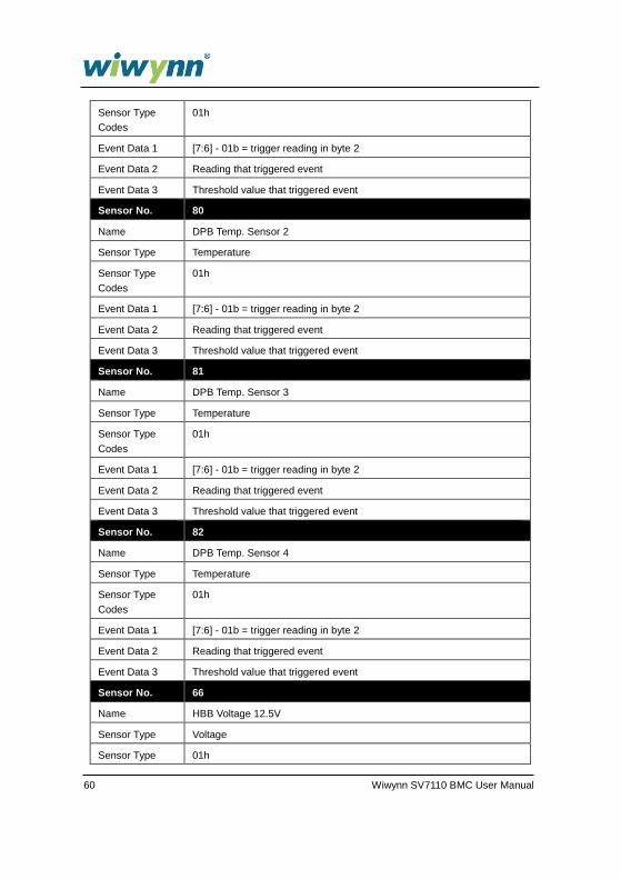
Sensor No. 79
Name DPB Temp. Sensor 1
Sensor Type Temperature
60 Wiwynn SV7110 BMC User Manual
Sensor Type
Codes
01h
Event Data 1 [7:6] - 01b = trigger reading in byte 2
Event Data 2 Reading that triggered event
Event Data 3 Threshold value that triggered event
Sensor No. 80
Name DPB Temp. Sensor 2
Sensor Type Temperature
Sensor Type
Codes
01h
Event Data 1 [7:6] - 01b = trigger reading in byte 2
Event Data 2 Reading that triggered event
Event Data 3 Threshold value that triggered event
Sensor No. 81
Name DPB Temp. Sensor 3
Sensor Type Temperature
Sensor Type
Codes
01h
Event Data 1 [7:6] - 01b = trigger reading in byte 2
Event Data 2 Reading that triggered event
Event Data 3 Threshold value that triggered event
Sensor No. 82
Name DPB Temp. Sensor 4
Sensor Type Temperature
Sensor Type
Codes
01h
Event Data 1 [7:6] - 01b = trigger reading in byte 2
Event Data 2 Reading that triggered event
Event Data 3 Threshold value that triggered event
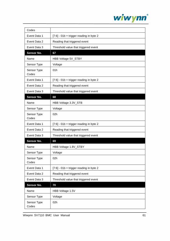
Sensor No. 66
Name HBB Voltage 12.5V
Sensor Type Voltage
Sensor Type 01h
Wiwynn SV7110 BMC User Manual 61
Codes
Event Data 1 [7:6] - 01b = trigger reading in byte 2
Event Data 2 Reading that triggered event
Event Data 3 Threshold value that triggered event
Sensor No. 67
Name HBB Voltage 5V_STBY
Sensor Type Voltage
Sensor Type
Codes
01h
Event Data 1 [7:6] - 01b = trigger reading in byte 2
Event Data 2 Reading that triggered event
Event Data 3 Threshold value that triggered event
Sensor No. 68
Name HBB Voltage 3.3V_STB
Sensor Type Voltage
Sensor Type
Codes
02h
Event Data 1 [7:6] - 01b = trigger reading in byte 2
Event Data 2 Reading that triggered event
Event Data 3 Threshold value that triggered event
Sensor No. 69
Name HBB Voltage 1.8V_STBY
Sensor Type Voltage
Sensor Type
Codes
02h
Event Data 1 [7:6] - 01b = trigger reading in byte 2
Event Data 2 Reading that triggered event
Event Data 3 Threshold value that triggered event
Sensor No. 70
Name HBB Voltage 1.5V
Sensor Type Voltage
Sensor Type
Codes
02h

62 Wiwynn SV7110 BMC User Manual
Event Data 1 [7:6] - 01b = trigger reading in byte 2
Event Data 2 Reading that triggered event
Event Data 3 Threshold value that triggered event
Sensor No. 71
Name HBB Voltage 0.9V_CTRL
Sensor Type Voltage
Sensor Type
Codes
02h
Event Data 1 [7:6] - 01b = trigger reading in byte 2
Event Data 2 Reading that triggered event
Event Data 3 Threshold value that triggered event
Sensor No. 72
Name HBB Voltage 0.9V_EXP
Sensor Type Voltage
Sensor Type
Codes
02h
Event Data 1 [7:6] - 01b = trigger reading in byte 2
Event Data 2 Reading that triggered event
Event Data 3 Threshold value that triggered event
Sensor No. 73
Name HB Voltage 12V
Sensor Type Voltage
Sensor Type
Codes
02h
Event Data 1 [7:6] - 01b = trigger reading in byte 2
Event Data 2 Reading that triggered event
Event Data 3 Threshold value that triggered event
Sensor No. 74
Name HB Current
Sensor Type Current
Sensor Type
Codes
03h
Event Data 1 [7:6] - 01b = trigger reading in byte 2

Wiwynn SV7110 BMC User Manual 63
Event Data 2 Reading that triggered event
Event Data 3 Threshold value that triggered event
Sensor No. 240
Name HBB Voltage 1.5EXP
Sensor Type Voltage
Sensor Type
Codes
02h
Event Data 1 [7:6] - 01b = trigger reading in byte 2
Event Data 2 Reading that triggered event
Event Data 3 Threshold value that triggered event
Sensor No. 83
Name HBB Ambient Temp. Sensor
Sensor Type Temperature
Sensor Type
Codes
01h
Event Data 1 [7:6] - 01b = trigger reading in byte 2
Event Data 2 Reading that triggered event
Event Data 3 Threshold value that triggered event
Sensor No. 84
Name HBB Expander Temp. Sensor
Sensor Type Temperature
Sensor Type
Codes
01h
Event Data 1 [7:6] - 01b = trigger reading in byte 2
Event Data 2 Reading that triggered event
Event Data 3 Threshold value that triggered event
Sensor No. 85
Name HBB SAS CTRL Temp. Sensor
Sensor Type Temperature
Sensor Type
Codes
01h
Event Data 1 [7:6] - 01b = trigger reading in byte 2
Event Data 2 Reading that triggered event

64 Wiwynn SV7110 BMC User Manual
Event Data 3 Threshold value that triggered event
Sensor No. 86
Name HBB Local Temp. Sensor
Sensor Type Temperature
Sensor Type
Codes
01h
Event Data 1 [7:6] - 01b = trigger reading in byte 2
Event Data 2 Reading that triggered event
Event Data 3 Threshold value that triggered event
Sensor No. 215
Name HBB Outlet Temp
Sensor Type Temperature
Sensor Type
Codes
01h
Event Data 1 [7:6] - 01b = trigger reading in byte 2
Event Data 2 Reading that triggered event
Event Data 3 Threshold value that triggered event
Sensor No. 151
Name 10G Ambient
Sensor Type Temperature
Sensor Type
Codes
01h
Event Data 1 [7:6] - 01b = trigger reading in byte 2
Event Data 2 Reading that triggered event
Event Data 3 Threshold value that triggered event
Sensor No. 152
Name SAS Ambient
Sensor Type Temperature
Sensor Type
Codes
01h
Event Data 1 [7:6] - 01b = trigger reading in byte 2
Event Data 2 Reading that triggered event
Event Data 3 Threshold value that triggered event

Wiwynn SV7110 BMC User Manual 65
Sensor No. 153
Name Exp Ambient
Sensor Type Temperature
Sensor Type
Codes
01h
Event Data 1 [7:6] - 01b = trigger reading in byte 2
Event Data 2 Reading that triggered event
Event Data 3 Threshold value that triggered event
Sensor No. 87
Name BJT Temp. Sensor 1
Sensor Type Temperature
Sensor Type
Codes
01h
Event Data 1 [7:6] - 01b = trigger reading in byte 2
Event Data 2 Reading that triggered event
Event Data 3 Threshold value that triggered event
Sensor No. 88
Name BJT Temp. Sensor 2
Sensor Type Temperature
Sensor Type
Codes
01h
Event Data 1 [7:6] - 01b = trigger reading in byte 2
Event Data 2 Reading that triggered event
Event Data 3 Threshold value that triggered event
Sensor No. 100
Name HDD SMART Temp. 00
Sensor Type Temperature
Sensor Type
Codes
01h
Event Data 1 [7:6] - 01b = trigger reading in byte 2
Event Data 2 Reading that triggered event
Event Data 3 Threshold value that triggered event

66 Wiwynn SV7110 BMC User Manual
Sensor No. 101
Name HDD SMART Temp. 01
Sensor Type Temperature
Sensor Type
Codes
01h
Event Data 1 [7:6] - 01b = trigger reading in byte 2
Event Data 2 Reading that triggered event
Event Data 3 Threshold value that triggered event
Sensor No. 102
Name HDD SMART Temp. 02
Sensor Type Temperature
Sensor Type
Codes
01h
Event Data 1 [7:6] - 01b = trigger reading in byte 2
Event Data 2 Reading that triggered event
Event Data 3 Threshold value that triggered event
Sensor No. 103
Name HDD SMART Temp. 03
Sensor Type Temperature
Sensor Type
Codes
01h
Event Data 1 [7:6] - 01b = trigger reading in byte 2
Event Data 2 Reading that triggered event
Event Data 3 Threshold value that triggered event
Sensor No. 104
Name HDD SMART Temp. 04
Sensor Type Temperature
Sensor Type
Codes
01h
Event Data 1 [7:6] - 01b = trigger reading in byte 2
Event Data 2 Reading that triggered event
Event Data 3 Threshold value that triggered event
Wiwynn SV7110 BMC User Manual 67
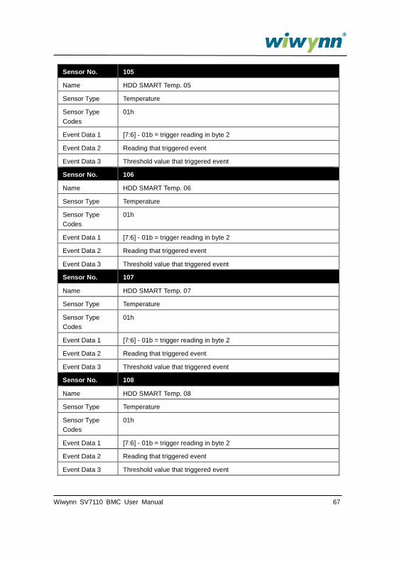
Sensor No. 105
Name HDD SMART Temp. 05
Sensor Type Temperature
Sensor Type
Codes
01h
Event Data 1 [7:6] - 01b = trigger reading in byte 2
Event Data 2 Reading that triggered event
Event Data 3 Threshold value that triggered event
Sensor No. 106
Name HDD SMART Temp. 06
Sensor Type Temperature
Sensor Type
Codes
01h
Event Data 1 [7:6] - 01b = trigger reading in byte 2
Event Data 2 Reading that triggered event
Event Data 3 Threshold value that triggered event
Sensor No. 107
Name HDD SMART Temp. 07
Sensor Type Temperature
Sensor Type
Codes
01h
Event Data 1 [7:6] - 01b = trigger reading in byte 2
Event Data 2 Reading that triggered event
Event Data 3 Threshold value that triggered event
Sensor No. 108
Name HDD SMART Temp. 08
Sensor Type Temperature
Sensor Type
Codes
01h
Event Data 1 [7:6] - 01b = trigger reading in byte 2
Event Data 2 Reading that triggered event
Event Data 3 Threshold value that triggered event

68 Wiwynn SV7110 BMC User Manual
Sensor No. 109
Name HDD SMART Temp. 09
Sensor Type Temperature
Sensor Type
Codes
01h
Event Data 1 [7:6] - 01b = trigger reading in byte 2
Event Data 2 Reading that triggered event
Event Data 3 Threshold value that triggered event
Sensor No. 110
Name HDD SMART Temp. 10
Sensor Type Temperature
Sensor Type
Codes
01h
Event Data 1 [7:6] - 01b = trigger reading in byte 2
Event Data 2 Reading that triggered event
Event Data 3 Threshold value that triggered event
Sensor No. 111
Name HDD SMART Temp. 11
Sensor Type Temperature
Sensor Type
Codes
01h
Event Data 1 [7:6] - 01b = trigger reading in byte 2
Event Data 2 Reading that triggered event
Event Data 3 Threshold value that triggered event
Sensor No. 112
Name HDD SMART Temp. 12
Sensor Type Temperature
Sensor Type
Codes
01h
Event Data 1 [7:6] - 01b = trigger reading in byte 2
Event Data 2 Reading that triggered event
Event Data 3 Threshold value that triggered event

Wiwynn SV7110 BMC User Manual 69
Sensor No. 113
Name HDD SMART Temp. 13
Sensor Type Temperature
Sensor Type
Codes
01h
Event Data 1 [7:6] - 01b = trigger reading in byte 2
Event Data 2 Reading that triggered event
Event Data 3 Threshold value that triggered event
Sensor No. 114
Name HDD SMART Temp. 14
Sensor Type Temperature
Sensor Type
Codes
01h
Event Data 1 [7:6] - 01b = trigger reading in byte 2
Event Data 2 Reading that triggered event
Event Data 3 Threshold value that triggered event
Sensor No. 119
Name PPC Watt
Sensor Type Power Supply
Sensor Type
Codes
02h
Event Data 1 [7:6] - 01b = trigger reading in byte 2
Event Data 2 Reading that triggered event
Event Data 3 Threshold value that triggered event
Sensor No. 120
Name HBB Watt
Sensor Type Power Supply
Sensor Type
Codes
02h
Event Data 1 [7:6] - 01b = trigger reading in byte 2
Event Data 2 Reading that triggered event
Event Data 3 Threshold value that triggered event

70 Wiwynn SV7110 BMC User Manual
Sensor No. 0
Name Expander protocol error
Sensor Type OEM
Sensor Type
Codes
C0h
Event Data 1 20h
Event Data 2 ffh
Event Data 3 ffh
Sensor No. 0
Name IOC FW update event
Sensor Type Version Change
Sensor Type
Codes
2Bh
Event Data 1 07h-Software or F/W Change detected with associated Entity was
successful.
Event Data 2 08h-other management controller firmware
Event Data 3 01h
Sensor No. 0
Name Expander FW update event
Sensor Type Version Change
Sensor Type
Codes
2Bh
Event Data 1 07h-Software or F/W Change detected with associated Entity was
successful.
Event Data 2 08h-other management controller firmware
Event Data 3 02h
Sensor No. 0
Name BIOS FW update event
Sensor Type Version Change
Sensor Type
Codes
2Bh
Event Data 1 07h-Software or F/W Change detected with associated Entity was
successful.
Event Data 2 09h-system firmware (EFI / BIOS) change
Wiwynn SV7110 BMC User Manual 71
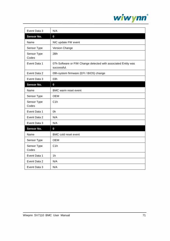
Event Data 3 N/A
Sensor No. 0
Name NIC update FW event
Sensor Type Version Change
Sensor Type
Codes
2Bh
Event Data 1 07h-Software or F/W Change detected with associated Entity was
successful.
Event Data 2 09h-system firmware (EFI / BIOS) change
Event Data 3 03h
Sensor No. 0
Name BMC warm reset event
Sensor Type OEM
Sensor Type
Codes
C1h
Event Data 1 0h
Event Data 2 N/A
Event Data 3 N/A
Sensor No. 0
Name BMC cold reset event
Sensor Type OEM
Sensor Type
Codes
C1h
Event Data 1 1h
Event Data 2 N/A
Event Data 3 N/A
72 Wiwynn SV7110 BMC User Manual
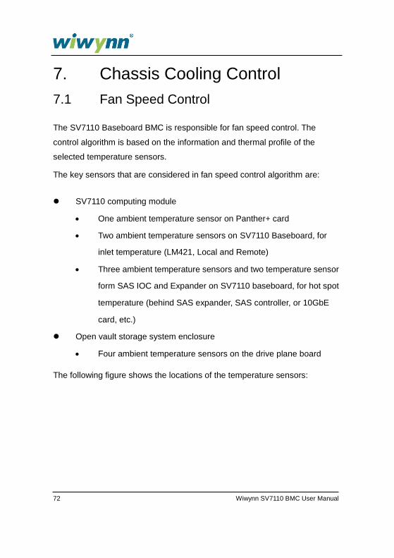
7. Chassis Cooling Control
7.1 Fan Speed Control
The SV7110 Baseboard BMC is responsible for fan speed control. The
control algorithm is based on the information and thermal profile of the
selected temperature sensors.
The key sensors that are considered in fan speed control algorithm are:
SV7110 computing module
One ambient temperature sensor on Panther+ card
Two ambient temperature sensors on SV7110 Baseboard, for
inlet temperature (LM421, Local and Remote)
Three ambient temperature sensors and two temperature sensor
form SAS IOC and Expander on SV7110 baseboard, for hot spot
temperature (behind SAS expander, SAS controller, or 10GbE
card, etc.)
Open vault storage system enclosure
Four ambient temperature sensors on the drive plane board
The following figure shows the locations of the temperature sensors:

Wiwynn SV7110 BMC User Manual 73
The SV7110 thermal control is designed to ensure that the temperatures of
all on-board key components (Intel Atom CPU, SAS controller, SAS
expander, etc.) and system components (such as hard disks) must meet the
thermal requirements with enough margins in all operating environment
temperature ranges.