Sure Coat Manual Gun Control Unit - Nordson
64
Sure Coatr Manual Gun Control Unit Customer Product Manual Part 237395H03 Issued 6/07 NORDSON CORPORATION AMHERST, OHIO USA For parts and technical support, call the Industrial Coating Systems Customer Support Center at (800) 433-9319 or contact your local Nordson representative. This document is subject to change without notice. Check http://emanuals.nordson.com for the latest version.
Transcript of Sure Coat Manual Gun Control Unit - Nordson

Sure Coat� Manual Gun Control Unit
Customer Product ManualPart 237395H03
Issued 6/07
NORDSON CORPORATION AMHERST, OHIO USA
For parts and technical support, call the Industrial CoatingSystems Customer Support Center at (800) 433-9319 or
contact your local Nordson representative.
This document is subject to change without notice.Check http://emanuals.nordson.com for the latest version.

Part 237395H03 � 2007 Nordson Corporation
Table of ContentsSafety 1-1. . . . . . . . . . . . . . . . . . . . . . . . . . . . . . . . . . . .Introduction 1-1. . . . . . . . . . . . . . . . . . . . . . . . . . . . . . . .Qualified Personnel 1-1. . . . . . . . . . . . . . . . . . . . . . . . .Intended Use 1-1. . . . . . . . . . . . . . . . . . . . . . . . . . . . . .Regulations and Approvals 1-2. . . . . . . . . . . . . . . . . .Personal Safety 1-2. . . . . . . . . . . . . . . . . . . . . . . . . . . .Fire Safety 1-2. . . . . . . . . . . . . . . . . . . . . . . . . . . . . . . .Grounding 1-3. . . . . . . . . . . . . . . . . . . . . . . . . . . . . . . . .Action in the Event of a Malfunction 1-4. . . . . . . . . . .Disposal 1-4. . . . . . . . . . . . . . . . . . . . . . . . . . . . . . . . . .
Description 2-1. . . . . . . . . . . . . . . . . . . . . . . . . . . . . . .Introduction 2-1. . . . . . . . . . . . . . . . . . . . . . . . . . . . . . .Modes 2-2. . . . . . . . . . . . . . . . . . . . . . . . . . . . . . . . . . . .
Standard Mode 2-2. . . . . . . . . . . . . . . . . . . . . . . . . .Automatic Feedback Current Function 2-2. . .
Select Charge Mode 2-2. . . . . . . . . . . . . . . . . . . . .Select Charge Mode #1 2-2. . . . . . . . . . . . . . . .Select Charge Mode #2 2-2. . . . . . . . . . . . . . . .Select Charge Mode #3 2-2. . . . . . . . . . . . . . . .Select Charge Mode #4 2-2. . . . . . . . . . . . . . .
Front Panel Controls and Indicators 2-3. . . . . . . . . . .Keypad 2-4. . . . . . . . . . . . . . . . . . . . . . . . . . . . . . . . .Display 2-5. . . . . . . . . . . . . . . . . . . . . . . . . . . . . . . . .
Power Switch 2-6. . . . . . . . . . . . . . . . . . . . . . . . . . . . . .Bottom Panel Components 2-7. . . . . . . . . . . . . . . . . .Timers 2-8. . . . . . . . . . . . . . . . . . . . . . . . . . . . . . . . . . . .
Spray Timer 2-8. . . . . . . . . . . . . . . . . . . . . . . . . . . . .Service Timer 2-8. . . . . . . . . . . . . . . . . . . . . . . . . . .Total Spray Timer 2-8. . . . . . . . . . . . . . . . . . . . . . . .
Specifications 2-8. . . . . . . . . . . . . . . . . . . . . . . . . . . . . .Electrical 2-8. . . . . . . . . . . . . . . . . . . . . . . . . . . . . . .Operating Pressure 2-9. . . . . . . . . . . . . . . . . . . . . .Air Supply Quality 2-9. . . . . . . . . . . . . . . . . . . . . . . .
Symbols 2-9. . . . . . . . . . . . . . . . . . . . . . . . . . . . . . . . . .
Installation 3-1. . . . . . . . . . . . . . . . . . . . . . . . . . . . . . . .Mounting 3-1. . . . . . . . . . . . . . . . . . . . . . . . . . . . . . . . . .
Operator Platform Rail Mounting Kit 3-1. . . . . . . .Wall Mounting Kit 3-1. . . . . . . . . . . . . . . . . . . . . . . .Bench Top Mounting Kit 3-1. . . . . . . . . . . . . . . . . .
Electrical Connections 3-2. . . . . . . . . . . . . . . . . . . . . .Pneumatic Connections 3-3. . . . . . . . . . . . . . . . . . . . .
Operation 4-1. . . . . . . . . . . . . . . . . . . . . . . . . . . . . . . . .Startup 4-1. . . . . . . . . . . . . . . . . . . . . . . . . . . . . . . . . . .Initial Gun Usage 4-3. . . . . . . . . . . . . . . . . . . . . . . . . . .
Configuring Gun Type—Only for Software Versions 3.0 and 4.0 4-3. . . . .
Operating Modes 4-4. . . . . . . . . . . . . . . . . . . . . . . . . .Select Charge Mode Examples 4-7. . . . . . . . . . . .
Error Conditions 4-9. . . . . . . . . . . . . . . . . . . . . . . . . . . .Air Pressure Adjustments 4-10. . . . . . . . . . . . . . . . . . . .
Fluidizing Air Pressure 4-10. . . . . . . . . . . . . . . . . . . .Flow Rate Air Pressure 4-10. . . . . . . . . . . . . . . . . . .Atomizing Air Pressure 4-10. . . . . . . . . . . . . . . . . . .
Shutdown 4-11. . . . . . . . . . . . . . . . . . . . . . . . . . . . . . . . .Daily Maintenance 4-11. . . . . . . . . . . . . . . . . . . . . . . . . .
Troubleshooting 5-1. . . . . . . . . . . . . . . . . . . . . . . . . .Introduction 5-1. . . . . . . . . . . . . . . . . . . . . . . . . . . . . . . .Diagnostics Mode 5-2. . . . . . . . . . . . . . . . . . . . . . . . . .
Operation 5-2. . . . . . . . . . . . . . . . . . . . . . . . . . . . . . .Error Codes 5-4. . . . . . . . . . . . . . . . . . . . . . . . . . . .Determining Software Version 5-5. . . . . . . . . . . . .Other Problems 5-6. . . . . . . . . . . . . . . . . . . . . . . . .
No Display at Startup 5-6. . . . . . . . . . . . . . . . . .Electrical Circuits 5-7. . . . . . . . . . . . . . . . . . . . .
Wiring Diagrams 5-8. . . . . . . . . . . . . . . . . . . . . . . .
Repair 6-1. . . . . . . . . . . . . . . . . . . . . . . . . . . . . . . . . . . .Keypad Module Replacement 6-1. . . . . . . . . . . . . . .DC Power Supply Replacement 6-3. . . . . . . . . . . . . .Manifold Replacement 6-4. . . . . . . . . . . . . . . . . . . . . .Solenoid Valve Rebuild 6-6. . . . . . . . . . . . . . . . . . . . . .Regulator/Gauge Replacement 6-8. . . . . . . . . . . . . . .
Parts 7-1. . . . . . . . . . . . . . . . . . . . . . . . . . . . . . . . . . . . .Introduction 7-1. . . . . . . . . . . . . . . . . . . . . . . . . . . . . . .
Using the Illustrated Parts List 7-1. . . . . . . . . . . .Control Unit 7-2. . . . . . . . . . . . . . . . . . . . . . . . . . . . . . . .Keypad Module 7-4. . . . . . . . . . . . . . . . . . . . . . . . . . . .Manifold Module 7-6. . . . . . . . . . . . . . . . . . . . . . . . . . .Power Supply Module 7-7. . . . . . . . . . . . . . . . . . . . . .Gauge/Regulator Module 7-9. . . . . . . . . . . . . . . . . . .Mounting Bracket Kits 7-10. . . . . . . . . . . . . . . . . . . . . . .Air Tubing 7-11. . . . . . . . . . . . . . . . . . . . . . . . . . . . . . . . .Service Kits 7-11. . . . . . . . . . . . . . . . . . . . . . . . . . . . . . . .Cable Adapter 7-11. . . . . . . . . . . . . . . . . . . . . . . . . . . . .
Contact UsNordson Corporation welcomes requests for information, comments, andinquiries about its products. General information about Nordson can befound on the Internet using the following address:http://www.nordson.com.Address all correspondence to:
Nordson CorporationAttn: Customer Service555 Jackson StreetAmherst, OH 44001
NoticeThis is a Nordson Corporation publication which is protected by copyright.Original copyright date 2000. No part of this document may bephotocopied, reproduced, or translated to another language without theprior written consent of Nordson Corporation. The information containedin this publication is subject to change without notice.
Trademarks
Nordson, the Nordson logo, Sure Coat, Select Charge, Versa-Spray, andTribomatic are registered trademarks of Nordson Corporation.

Safety 1-1
Part 237395H03� 2007 Nordson Corporation
Section 1Safety
Introduction Read and follow these safety instructions. Task- and equipment-specificwarnings, cautions, and instructions are included in equipmentdocumentation where appropriate.
Make sure all equipment documentation, including these instructions, isaccessible to all persons operating or servicing equipment.
Qualified Personnel Equipment owners are responsible for making sure that Nordson equipmentis installed, operated, and serviced by qualified personnel. Qualifiedpersonnel are those employees or contractors who are trained to safelyperform their assigned tasks. They are familiar with all relevant safety rulesand regulations and are physically capable of performing their assignedtasks.
Intended Use Use of Nordson equipment in ways other than those described in thedocumentation supplied with the equipment may result in injury to personsor damage to property.
Some examples of unintended use of equipment include
� using incompatible materials
� making unauthorized modifications
� removing or bypassing safety guards or interlocks
� using incompatible or damaged parts
� using unapproved auxiliary equipment
� operating equipment in excess of maximum ratings
Regulations and Approvals Make sure all equipment is rated and approved for the environment in whichit is used. Any approvals obtained for Nordson equipment will be voided ifinstructions for installation, operation, and service are not followed.
All phases of equipment installation must comply with all federal, state, andlocal codes.

Safety1-2
Part 237395H03 � 2007 Nordson Corporation
Personal Safety To prevent injury follow these instructions.
� Do not operate or service equipment unless you are qualified.
� Do not operate equipment unless safety guards, doors, or covers areintact and automatic interlocks are operating properly. Do not bypass ordisarm any safety devices.
� Keep clear of moving equipment. Before adjusting or servicing anymoving equipment, shut off the power supply and wait until theequipment comes to a complete stop. Lock out power and secure theequipment to prevent unexpected movement.
� Relieve (bleed off) hydraulic and pneumatic pressure before adjusting orservicing pressurized systems or components. Disconnect, lock out,and tag switches before servicing electrical equipment.
� Obtain and read Material Safety Data Sheets (MSDS) for all materialsused. Follow the manufacturer’s instructions for safe handling and useof materials, and use recommended personal protection devices.
� To prevent injury, be aware of less-obvious dangers in the workplacethat often cannot be completely eliminated, such as hot surfaces, sharpedges, energized electrical circuits, and moving parts that cannot beenclosed or otherwise guarded for practical reasons.
Fire Safety To avoid a fire or explosion, follow these instructions.
� Do not smoke, weld, grind, or use open flames where flammablematerials are being used or stored.
� Provide adequate ventilation to prevent dangerous concentrations ofvolatile materials or vapors. Refer to local codes or your material MSDSfor guidance.
� Do not disconnect live electrical circuits while working with flammablematerials. Shut off power at a disconnect switch first to preventsparking.
� Know where emergency stop buttons, shutoff valves, and fireextinguishers are located. If a fire starts in a spray booth, immediatelyshut off the spray system and exhaust fans.
� Clean, maintain, test, and repair equipment according to the instructionsin your equipment documentation.
� Use only replacement parts that are designed for use with originalequipment. Contact your Nordson representative for parts informationand advice.

Safety 1-3
Part 237395H03� 2007 Nordson Corporation
Grounding WARNING: Operating faulty electrostatic equipment is hazardous and cancause electrocution, fire, or explosion. Make resistance checks part of yourperiodic maintenance program. If you receive even a slight electrical shockor notice static sparking or arcing, shut down all electrical or electrostaticequipment immediately. Do not restart the equipment until the problem hasbeen identified and corrected.
Grounding inside and around the booth openings must comply with NFPArequirements for Class II, Division 1 or 2 Hazardous Locations. Refer toNFPA 33, NFPA 70 (NEC articles 500, 502, and 516), and NFPA 77, latestconditions.
� All electrically conductive objects in the spray areas shall be electricallyconnected to ground with a resistance of not more than 1 megohm asmeasured with an instrument that applies at least 500 volts to the circuitbeing evaluated.
� Equipment to be grounded includes, but is not limited to, the floor of thespray area, operator platforms, hoppers, photoeye supports, andblow-off nozzles. Personnel working in the spray area must begrounded.
� There is a possible ignition potential from the charged human body.Personnel standing on a painted surface, such as an operator platform,or wearing non-conductive shoes, are not grounded. Personnel mustwear shoes with conductive soles or use a ground strap to maintain aconnection to ground when working with or around electrostaticequipment.
� Operators must maintain skin-to-handle contact between their hand andthe gun handle to prevent shocks while operating manual electrostaticspray guns. If gloves must be worn, cut away the palm or fingers, wearelectrically conductive gloves, or wear a grounding strap connected tothe gun handle or other true earth ground.
� Shut off electrostatic power supplies and ground gun electrodes beforemaking adjustments or cleaning powder spray guns.
� Connect all disconnected equipment, ground cables, and wires afterservicing equipment.
Action in the Event of a Malfunction If a system or any equipment in a system malfunctions, shut off the systemimmediately and perform the following steps:
� Disconnect and lock out electrical power. Close pneumatic shutoffvalves and relieve pressures.
� Identify the reason for the malfunction and correct it before restarting theequipment.
Disposal Dispose of equipment and materials used in operation and servicingaccording to local codes.

Safety1-4
Part 237395H03 � 2007 Nordson Corporation

Description 2-1
Part 237395H03� 2007 Nordson Corporation
Section 2Description
Introduction See Figure 2-1.
The Sure Coat manual gun control unit provides pneumatic and electrostaticcontrols, dc power, and monitoring functions for Sure Coat and Versa-Spraymanual powder spray guns.
The control unit provides the voltage output to the Integral PowerSupply (IPS) and monitors the feedback current from the spray gun tocontrol the electrostatic charging of the powder.
Three versions of the control unit are available: a standard unit, and 115Vand 220V units with vibratory motor control.
The units with vibratory motor control turns the vibrating motor on wheneverthe spray gun is triggered and remains running for approximately 30seconds after the spray gun is triggered off.
The control status information and parameters are adjusted and viewedfrom a front panel keypad and the liquid crystal display (LCD). The LCDprovides status information to the operator to identify the mode of operation,the control parameter set point values, and the status of the control unit’soutput. The front panel keys allow the operator to choose between thedifferent control modes and to set the electrostatic output levels.
The control unit provides low-voltage dc power to the spray gun voltagemultiplier. The multiplier produces the electrostatic voltage used to chargethe powder as it is sprayed.
Figure 2-1 Sure Coat Manual Gun Control Unit

Description2-2
Part 237395H03 � 2007 Nordson Corporation
ModesThe control unit provides several modes of operation.
Standard ModeThe standard mode (STD) provides maximum transfer efficiency whencoating large objects with a gun-to-part distance of 0.2−0.3 m (8−12 in.).Only kV can be controlled in standard mode.
Automatic Feedback Current FunctionThe Automatic Feedback Current (AFC) is a function that is available in thestandard mode. The spray gun’s maximum current output is controlledaccording to the operator adjusted set point. The A output is called the setpoint. This allows the operator to limit the maximum output current of thespray gun and prevents excess charging of the powder. AFC provides foran optimum combination of kV and electric field strength for coating partswith interior corners and deep recesses at close range.
Select Charge ModeThe Select Charge mode allows the operator to select different electrostaticcharging values from the controller, to optimize the coating of parts withdifferent shapes.
Select Charge Mode #1This mode is for recoating. It is specifically designed for recoatingoperations to delay back-ionization and to minimize picture-framing.
Select Charge Mode #2This mode is for touch-up work. It is optimized for touch-up operations tofacilitate Faraday penetration.
Select Charge Mode #3This mode is for deep cavities. It is designed to coat deep cavities from theinside to minimize back ionization on the edges while providing high transferefficiency inside the cavities.
Select Charge Mode #4 This mode is custom-programmable. It allows both the kV and AFC setpoints to be adjusted to specific application requirements.
NOTE: Select Charge mode #4 is only available with software version 4.0.

Description 2-3
Part 237395H03� 2007 Nordson Corporation
Front Panel Controls and IndicatorsSee Figure 2-2.
The controller’s front panel is separated into two sections. The left sectioncontains a keypad and display. The right section contains regulators andgauges for the adjustment of flow rate, atomizing, and auxiliary airpressures. The auxiliary air regulator and gauge typically are used toprovide fluidizing air to either a feed hopper or fluidizing adapter used with avibratory box feeder.
1 2 3 4
Figure 2-2 Front Panel Controls and Indicators
1. Front panel keypad and display2. Flow rate air regulator and gauge
3. Atomizing air regulator andgauge
4. Auxiliary air regulator andgauge

Description2-4
Part 237395H03 � 2007 Nordson Corporation
KeypadRefer to Figure 2-3 and Table 2-1. The front panel keys are grouped aroundthe display.
1 2 3 4 5
6
78
9
10
11
Figure 2-3 Front Panel Keypad and Display
Table 2-1 Front Panel Keypad and Display
Item Component Function
1 STD light STD mode green indicator light.
2 STD key Turns on the standard electrostatic operating mode (kVcontrol mode).
3 SELECT CHARGE light Select Charge mode green indicator light.
4 SELECT CHARGE key Turns on the Select Charge mode. The Select Chargemode number is shown on the display. Pressing theSELECT CHARGE key repeatedly cycles through themodes.
5 Display Refer to Display on page 2-5.
6 Up arrow key Increases the set point value. Pressing the keycontinuously causes the value to increase quickly untilthe maximum value is reached.
7 Down arrow key Decreases the set point value. Pressing the keycontinuously causes the value to decrease quickly untilthe minimum value is reached. If viewing the spraytimer, the timer is cleared. Pressing this key while in thediagnostics mode clears faults.
8 Nordson (diagnostics) logokey
Puts the controller into the diagnostics mode. The unitenters the CONFIG mode if this key is pressed duringpower up.
9 VIEW key Toggles through various display options on the digitaldisplay and the bar graph.
10 AFC key Turns on and off the AFC function and the correspondingindicator light.
11 AFC light AFC function yellow indicator light.

Description 2-5
Part 237395H03� 2007 Nordson Corporation
DisplayRefer to Figure 2-4 and Table 2-2. The display contains the status of thepowder spray, electrostatics, and the set point. A bar graph is also presentfor a visual representation of the digital display.
1 2 3 5 6
7
8
9
10
11
4
Figure 2-4 Display Indicators
Table 2-2 Display Indicators
Item Component Description
1 Select Charge mode Indicates which Select Charge mode is currently active.Number range is from 1 to 3.
2 F1 F2 Not an active function.
3 Powder icon Indicates that the spray gun is triggered and powder flowis on.
4 Digital display Shows a digital number of the set point and actualparameter information (kV, A, and HRS).
5 Electrostatics icon Lights to indicate that the spray gun is triggered and theelectrostatics are on.
6 Purge icon Lights to indicate that the purge function is activated.
7 Unit indicator Lights to indicate the selection of kV, A, HRS, type oftimer, or if an alarm is present.
8 Bar graph units Shows the units of the bar graph indicator.
9 Bar graph Shows the parameter displayed on the digital display asa bar graph.
10 Alarm icon Lights when there is an alarm or error condition.
11 Diagnostics icon Lights to indicate that the controller is in the diagnosticsmode.

Description2-6
Part 237395H03 � 2007 Nordson Corporation
Power SwitchSee Figure 2-5.
The side panel contains the main power switch that turns on and off the acpower to the control unit.
POWER
1
Figure 2-5 Control Unit Power Switch (Side Panel)
1. Control unit power switch

Description 2-7
Part 237395H03� 2007 Nordson Corporation
Bottom Panel ComponentsRefer to Figure 2-6 and Table 2-3. Flip the control unit on its back to accessthe components on the bottom panel.
INPUT: 85−250VAC 50−60 Hz,/1Ø, 2 AMP
GUN OUTPUTPOWER INPUT
F1 2A250VAC
F2 2A250VAC
2 1
3
10 9
8
65
4
7
11
Figure 2-6 Bottom Panel Components
Table 2-3 Bottom Panel Components
Item Component Function
1 IN air connector 10-mm tubing connector for supply air input. 7 bar(100 psi) maximum.
2 Purge air connector 6-mm tubing connector for purge air output to the spraygun. Air pressure is unregulated at full supply pressure.
3 Gun air connector 4-mm tubing connector for gun air output. Air pressure isunregulated. A restrictor is supplied to reduce the airpressure to the spray gun for the electrode air washfunction.
4 Atomizing air connector 8-mm tubing connector for the powder pump atomizingair supply from the atomizing air regulator.
5 Flow rate air connector 8-mm tubing connector for the powder pump flow rate airsupply from the flow air regulator.
6 AUX air connector 10-mm tubing connector for unswitched auxiliary airoutput from the AUX regulator. Typically used forfluidizing air for a feed hopper.
7 Fuses Protect the control unit from power surges.
8 Cabinet ground stud Ground wire connection. The control unit must beconnected to a true earth ground.
9 GUN OUTPUT receptacle 6-pin receptacle for the gun cable.
10 POWER INPUT receptacle 5-pin receptacle for the ac power input to the controller.
11 Vibratory motor control Connection for the vibratory motor control unit
Not Shown Small air holes Small holes through the panel by the air fittings are thesolenoid exhaust air holes. They should not be plugged.

Description2-8
Part 237395H03 � 2007 Nordson Corporation
TimersThe control unit is equipped with three different timer functions.
Spray TimerThe spray timer is indicated in hours (HRS) and keeps track of how long thespray gun has been triggered. This is a cumulative total that can be reset.The spray timer can be viewed by pressing the VIEW key while the spraygun is not triggered. The system can be reset by pressing the down arrowwhile viewing the spray hours.
This feature is used for preventive maintenance.
Service TimerThe service timer keeps track of how long the controller has been in service.This timer can be viewed by pressing the Nordson key and going into thediagnostics mode. Time is shown as HRS x 10. The number displayedmust be multiplied by 10.
This timer cannot be reset and is used for diagnostic purposes.
Total Spray TimerNOTE: The total spray timer is not available in software version 1.0.
The total spray timer keeps track of the total time the spray gun has beentriggered. This timer can be viewed by pressing the Nordson key to go intothe diagnostics mode. Time is shown in HRS x 10.
This timer can not be reset and is used for diagnostic purposes.
SpecificationsThe control unit enclosure meets IP54 and Class II, Division II requirements.
Electrical
Input 85−250 Vac, 1 phase, 50−60 Hz
Output 6−21 Vdc to spray gun
Short circuit output current 300 mA
Maximum output current 600 mA

Description 2-9
Part 237395H03� 2007 Nordson Corporation
Operating Pressure
Minimum input pressure 4 bar (60 psi)
Maximum input pressure 7 bar (100 psi)
Flow rate air 1 bar (15 psi)
Atomizing air 0.3 bar (5 psi)
Auxiliary air (fluidizing) 1.0−2.8 bar (15−40 psi)
Gun air 0.3 bar (5 psi) fixed
Purge air Full input air pressure
Air Supply QualityThe supply air must be clean and dry. Use a regenerative desiccant orrefrigerated air dryer capable of producing a 3.4 �C (38 �F) or lower dewpoint at 7 bar (100 psi) and a filter system with prefilters andcoalescent-type filters capable of removing oil, water and dirt in thesubmicron range.
SymbolsFigure 2-7 identifies the symbols used on the control unit.
OFF ON FLOW-RATEAIR
ATOMIZINGAIR
GUN AIR PURGE AIR ELECTROSTATICS GROUND
Figure 2-7 Symbol Legend

Description2-10
Part 237395H03 � 2007 Nordson Corporation

Installation 3-1
Part 237395H03� 2007 Nordson Corporation
Section 3Installation
WARNING: Allow only qualified personnel to perform the following tasks.Follow the safety instructions in this document and all other relateddocumentation.
MountingThree mounting options are available for the manual gun control unit. Themounting kits must be specified and ordered separately. Refer to MountingBracket Kits on page 7-10.
Operator Platform Rail Mounting Kit1. Attach the rail bracket to the front of the control unit with the four screws.
2. Start threading the locking bolts with nuts into the front of the railbracket, but do not tighten them.
3. Install the controller onto the rail.
4. Tighten the locking bolts and nuts.
Wall Mounting Kit1. Attach the wall bracket to the front of the control unit with the four
screws.
2. Using the bracket as a template, drill holes in the mounting surface.
3. Secure the wall bracket to the mounting surface.
Bench Top Mounting Kit1. Attach the bench top mounting bracket to the unit with the four screws.
2. Using the bracket as a template, drill holes in the bench top.
3. Secure the bench top mounting bracket to the mounting surface.

Installation3-2
Part 237395H03 � 2007 Nordson Corporation
Electrical Connections
WARNING: Do not skip step 1. Failure to install the locking disconnectswitch or breaker may result in a severe shock during installation or repair.
CAUTION: Equipment damage may occur if the control unit is connected toany line voltage other than that stated on the ID plate.
1. Install a locking disconnect switch or breaker in the service line ahead ofthe equipment so power can be shut off during installation or repair.
2. Make sure that the input voltage is 85−240 Vac nominal, 1 phase,50/60 Hz.
NOTE: If you are using the vibratory motor control option, theinput power must match the rating of the motor.
3. Wire the unterminated end of the power cord using these guidelines:
Wire Type
Brown L1 (hot)
Blue L2 (neutral)
Green/yellow Ground
WARNING: All electrically conductive equipment in the spray area must begrounded. Ungrounded or poorly grounded equipment can store anelectrostatic charge which can give personnel a severe shock or arc andcause a fire or explosion.
4. Connect the ground strap furnished with the control unit to the groundstud.
5. Secure the ground strap’s clamp to an earth ground.
6. Connect the power cord’s plug to the POWER INPUT receptacle.
7. Connect the gun cable to the GUN OUTPUT receptacle.

Installation 3-3
Part 237395H03� 2007 Nordson Corporation
Pneumatic ConnectionsMaximum input air pressure is 7 bar (100 psi). The supply air must be cleanand dry. Moist or contaminated air can cause powder to cake in the feedhopper; stick to the feed hose walls; clog the pump venturi throats and gunpassages; and cause grounding or arcing inside the spray gun.
Use prefilters and coalescent filters with automatic drains and a refrigeratedor regenerative desiccant air dryer capable of producing a 3.4 �C (38 �F) orlower dewpoint at 7 bar (100 psi).
NOTE: The unit is shipped with 10-, 8-, and 6-mm tubing connectorsinstalled in the input and output ports. Refer to your spray gun, pump, andhopper manuals for locations of connections listed in the Other Connectioncolumn.
See Figure 2-6.
Air TubingSize
Air TubingColor
Controller Connection(Bottom Panel)
Other Connection
10 mm Blue IN air connector (1) Main air supply
NOTE: Install a manuallyoperated, self-relieving shutoffvalve in the supply line to thecontrol unit.
6 mm Black Purge air connector (2) Spray gun
4 mm Clear Gun air connector (3) Spray gun
8 mm Blue Atomizing air connector (4) Powder pump fitting A
8 mm Black Flow rate air connector (5) Powder pump fitting F
10 mm Black AUX 1 air connector (6) Fluidizing air fitting (on feed hopperor fluidizing pickup tube)

Installation3-4
Part 237395H03 � 2007 Nordson Corporation

Operation 4-1
Part 237395H03� 2007 Nordson Corporation
Section 4Operation
WARNING: Allow only qualified personnel to perform the following tasks.Follow the safety instructions in this document and all other relateddocumentation.
WARNING: This equipment can be dangerous unless it is used inaccordance with the rules laid down in this manual.
WARNING: All electrically conductive equipment in the spray area must begrounded. Ungrounded or poorly grounded equipment can store anelectrostatic charge which can give personnel a severe shock or arc andcause a fire or explosion.
Startup Before operating a Nordson powder spray system, read all the systemcomponent manuals.
NOTE: For information on the operation of components of the powderspray system, refer to the appropriate manuals.
Before powering on the manual gun control unit, make sure that thefollowing conditions are met.
� The booth exhaust fans must be turned on.
� The powder recovery system must be operating.
� The powder in the feed hopper must be thoroughly fluidized.
� The cable, feed hose, and air tubing must be correctly connected to thespray gun, powder pump, and control unit.

Operation4-2
Part 237395H03 � 2007 Nordson Corporation
Startup (contd)
See Figure 4-1.
1. Turn the control unit main power switch to the on position. All the iconson the LCD panel light. The controller switches to the factory defaultmode or to the last selected mode. The LCD displays the kV or Asetting.
Figure 4-1 STD Mode Display, Spray Gun Not Triggered
2. Set the air pressures using the guidelines listed in the following chart.
NOTE: The pressures given are average starting points. Pressuresvary according to required film build, line speed, and part configuration.Adjust the pressures to obtain the desired results.
Flow Rate 1 bar (15 psi)
Atomizing 0.3 bar (5 psi)
AUX (Fluidizing) 0−2 bar (0−30 psi)
NOTE: Before spraying, allow 5−10 minutes for the powder in the feedhopper to adequately fluidize.
WARNING: The operator must maintain skin contact with the gun handle.If wearing gloves, cut away the palm. Failure to observe this warning couldresult in a shock.
3. Point the spray gun into the booth, pull the trigger, and test the spraypattern.
NOTE: The typical display is shown in Figure 4-2 when the spray gun istriggered. Refer to the Description section for additional information onthis display.
NOTE: If you are using the vibratory motor control option, the vibratingmotor will turn on as the spray gun is triggered and will remain on untilapproximately 30 seconds after the trigger is released.

Operation 4-3
Part 237395H03� 2007 Nordson Corporation
4. Adjust the flow rate, and atomizing air pressures and the pattern adjustsleeve (if used) to obtain the desired spray pattern.
5. Select an operating mode using Tables 4-1, 4-2, 4-3, or 4-4.
Figure 4-2 STD Mode Display, AFC On, Spray Gun Triggered
Initial Gun UsageWhen a spray gun is first put into service, verify that the control unit is in theSTD mode with AFC turned on, at a set point of 30 A (software versions2.0, 3.0, 4.0, 5.0 only).
1. Record the A output with no parts in front of the spray gun.
2. Monitor the A output daily under the same conditions.
NOTE: A significant increase in A output indicates a probable short inthe gun resistor. A significant decrease indicates a failing resistor orvoltage multiplier.
3. Select an operating mode using Tables 4-1, 4-2, 4-3, or 4-4.
NOTE: Refer to the Description section for additional information onSelect Charge and Standard modes.
Configuring Gun Type—Only for Software Versions 3.0, 4.0, and 5.0The default spray gun type is the Sure Coat manual powder spray gun.Perform the following procedure to switch between Sure Coat andVersa-Spray powder spray guns.
1. Depress and hold the Nordson logo key and turn on the control unit.
2. Hold the Nordson logo key until CFG appears on the display. CHOOSEGUN scrolls across the display.
3. Either press the VIEW key or wait until SC appears on the display.
4. Use the arrow keys to select either Sure Coat (SC) or Versa-Spray (VS).
5. Press the Nordson logo key to exit the CONFIG mode.

Operation4-4
Part 237395H03 � 2007 Nordson Corporation
Operating Modes
Table 4-1 Operating Modes—Software Versions 2.0, 3.0, and 4.0
Mode AFC Description
Standard Off See Figure 4-3. Use the up/down arrow keys to turn the kV on/off or adjust theset point. The control unit stores the kV setting when the mode is changed orwhen the control unit is powered off.
Setting Sure CoatConfigurations
Versa-SprayConfigurations
kV Set Point adjustable adjustable
kV Range 0 then 25 to 95 kV 0 then 25 to 80 kV
Maximum kVOutput/Default Setting
95 kV 80 kV
On See Figure 4-3. Adjust the desired AFC set point by using the up/down keys.The factory-preset starting point is 30 A. If the set point is changed, thecontroller remembers the new set point value.
Voltage is automatically set to the maximum, and AFC allows the setting of afeedback current threshold. If the current threshold is reached, the voltage isautomatically adjusted to maintain the required coverage.
If the AFC set point is changed, the controller remembers the new set pointvalue.
Setting Sure CoatConfigurations
Versa-SprayConfigurations
Initial kV Value 95 kV (not adjustable) 80 kV (not adjustable)
Set Point Increments 5 A 5 A
kV Range 10 to 100 A 10 to 120 A
Default Set Point 30 A(Default set point for software version 1.0: 20 A)
Maximum Current 100 A 120 A
1400470A
Figure 4-3 STD Mode with AFC On

Operation 4-5
Part 237395H03� 2007 Nordson Corporation
Table 4-2 Select Charge Modes—Software Version 4.0
Mode Description
Select Charge Application Select Charge Mode
Re-coat 1
Touch-up 2
Deep cavity with spray gun inside 3
Custom (user programmable) 4
See Figure 4-4. Select the desired Select Charge value (based on the application andcoating requirements) by depressing the Select Charge key.
Mode #1 Mode #2 Mode #3 Mode #4
Sure CoatInitial kVValue:
95 kV 95 kV 95 kV 60 kV
Versa-SprayInitial kVValue:
80 kV 80 kV 80 kV 60 kV
Set Point: not adjustable not adjustable not adjustable adjustable
MaximumCurrent
15 A 50 A 70 A 30 A
Figure 4-4 Select Charge Mode

Operation4-6
Part 237395H03 � 2007 Nordson Corporation
Operating Modes (contd)
Table 4-3 Select Charge Modes—Software Versions 3.0 and 2.0
Mode Description
Select Charge Application Select Charge Mode
Re-coat 1
Touch-up 2
Deep cavity with spray gun inside 3
See Figure 4-5. Select the desired Select Charge value (based on the application andcoating requirements) by depressing the Select Charge key.
Mode #1 Mode #2 Mode #3
Sure Coat Initial kVValue:
95 kV 95 kV 95 kV
Versa-Spray InitialkV Value:
80 kV 80 kV 80 kV
Set Point: not adjustable not adjustable not adjustable
Maximum Current 15 A 50 A 70 A
NOTE: The kV and AFC set points are not user adjustable and are set for optimumoutput for the mode.
Figure 4-5 Select Charge Mode

Operation 4-7
Part 237395H03� 2007 Nordson Corporation
Table 4-4 Select Charge Modes—Software Version 1.0
Mode AFC Description
Select Charge On See Figure 4-6. Adjust the desired AFC set point by using the up/downkeys. A suggested starting point is 20 A. If the set point is changed, thecontrol unit remembers the new set point value. The default AFC set pointcan be different for Select Charge modes 2 or 3. AFC cannot be set invalue 1.
Voltage is automatically set to the maximum, and AFC allows the setting ofa feedback current threshold. If the current threshold is reached, thevoltage is automatically adjusted to maintain the required coverage. ThekV is set to that particular mode’s initial kV value.
Mode #1 Mode #2 Mode #3
Initial kV value 95 95 95
kV set point not adjustable not adjustable not adjustable
AFC set point not adjustable 10 − 50 10 − 100
Maximumcurrent
15 A 50 A 100 A
Figure 4-6 Select Charge Mode with AFC On
Select Charge Mode ExamplesMode Application
1 When recoating parts that have already been cured but require additional coating andcuring, the gun current should be limited and maintained.
2 When coating large parts with a mix of large flat sections and recessed or angledsections, high kV is required for painting the flat sections at a far gun to part distance, butlow voltage from the gun is required for painting the recessed sections at a close gun topart distance.
3 When coating parts with deep cavities, low kV and low current are required to coat thecorners, but high kV and high current are required to coat the flat sections inside.
4 Version 4.0 Only
When spraying special powders (metallics, micas, etc.) where application-specific lowinitial kV and AFC allow for more uniform charging of powder particles.

Operation4-8
Part 237395H03 � 2007 Nordson Corporation
Operating Modes (contd)
Verify the correct data on the display in Table 4-5.
Coat a part and adjust the voltage settings (kV or AFC) and air pressures toachieve the desired results.
NOTE: Obtaining a high quality finish and maximum transfer efficiency(percentage of powder sprayed that adheres to the part) requiresexperimentation and experience. Settings for electrostatic voltage and airpressure affect overall coating performance. In most applications, thesettings should produce a soft spray pattern that directs as much of thepowder as possible onto the part with a minimum of overspray. Thesesettings allow the maximum amount of charged powder to be attracted tothe grounded part.
NOTE: Lowering the voltage is a common method for trying to improvecoverage of deep recesses and interior corners of parts. However, loweringthe voltage may also reduce the overall transfer efficiency. Powder velocity,direction, and pattern shape can be just as important as electrostaticvoltage in coating these areas.
Table 4-5 Displays
Function Display when gun triggered(1) Display when gun not triggered
STD Mode & Viewing kV Version 1.0, 2.0, 4.0, and 5.0:kV set point
Version 3.0:Actual kV
kV setting
AFC On & Viewing kV Actual kV Initial kV setting (factory kV)
AFC On & Viewing A Actual A(2) AFC set point(3)
AFC Off & Viewing kV kV set point kV set point
AFC Off & Viewing A Actual A Blank(1) Use the VIEW key to toggle the display between kV and A values. The units are shown on the displayand the bar graph.(2) Pressing the AFC key shows the AFC set point then the actual A current feedback from the spray gunon the display and the bar graph.(3) Pressing the up or down key switches the display to AFC set point. All subsequent key presseschange the AFC set point.

Operation 4-9
Part 237395H03� 2007 Nordson Corporation
Error ConditionsThe Sure Coat control unit continuously monitors the operation of vitalsystem components. The question mark (?) error icon alerts the operatorabout potential faults to prevent rejects and to reduce downtime. Theautomatic self diagnostics pinpoint a faulty component to facilitatetroubleshooting and also reduces downtime.
See Figure 4-7.
If the question mark (?) error icon appears on the display, refer to theTroubleshooting section.
Icon Icon Status Gun Status Problem
Flashing Triggered Electrostatics
Flashing Not triggeredkV is on when itshould be off
Flashing Triggered Solenoid
On continuously TriggeredPress theNordson key toview error code
1400473A
Figure 4-7 Display of an Error Condition

Operation4-10
Part 237395H03 � 2007 Nordson Corporation
Air Pressure AdjustmentsRefer to the feed hopper manual for the recommended fluidizing airpressure and to Specifications on page 2-8 for recommended flow rate andatomizing air pressures.
Fluidizing Air PressureWhen properly fluidized, small air bubbles should rise gently and uniformlyto the surface of the powder, making it look like it is boiling. In this state, thepowder feels and acts similar to a liquid, enabling it to be easily transportedby the powder pump from the hopper to the spray gun.
If the fluidizing pressure is set too low, a heavy inconsistent powder mayflow. If the fluidizing pressure is too high, the powder boils violently and theflow is uneven with possible air pockets in the powder stream.
Flow Rate Air PressureFlow rate air transports a powder and air mixture from the feed hopper tothe spray gun. Increasing the flow rate air pressure increases the amountof powder sprayed from the spray gun and may increase the thickness ofthe powder deposited on the part.
If the flow rate air pressure is set too low, an inadequate film build or unevenpowder output may result. If the flow rate air pressure is too high, too muchpowder could be output at too high a velocity. This could cause excessivefilm build or overspray, which reduces transfer efficiency and wastespowder. Excessive flow rate air pressure may also accelerate the build-upof impact fused powder (impact fusion) in the spray gun or pump or causepremature wear of the spray gun and pump parts in contact with thepowder.
Keeping the amount of overspray to a minimum reduces the amount ofpowder to be recovered and recycled. This minimizes wear and tear on thesystem components such as pumps, spray guns, and filters. Maintenancecosts are also kept down.
Atomizing Air Pressure Atomizing air is added to the powder and air stream to increase the powdervelocity in the feed hose and break up clumps of powder. Higher atomizingair pressures are needed at lower powder flow rates to keep the powderparticles suspended in the air stream. Higher powder velocities may causethe spray pattern to change.
Operation 4-11
Part 237395H03� 2007 Nordson Corporation
If the atomizing air pressure is set too low, the result may be uneven powderoutput from the spray gun along with puffing and surging. If set too high,atomizing air pressure can increase the powder velocity and causeexcessive overspray, impact fusion, and premature wear of the pump andspray gun parts.
NOTE: Set the atomizing air at least to 0.3 bar (5 psi). If the air pressure istoo low, powder may flow back from the powder pump and get inside thecontrol unit, damaging the air valves and regulators.
Shutdown1. Turn the control unit’s main power switch to the off position.
2. If using auxiliary air, turn the AUX regulator counterclockwise until thegauge reads zero.
3. Ground the gun electrode to discharge any residual voltage.
4. Perform the Daily Maintenance procedure.
Daily Maintenance1. Compare the spray gun’s A output in kV mode with no parts in front of
the spray gun, with the output and kV setting recorded at initial startup.Significant differences may mean that the gun electrode assembly ormultiplier is shorted or failed.
WARNING: Check all ground connections thoroughly. Ungroundedequipment and parts may accumulate a charge that could arc and cause afire or explosion. Failure to observe this warning could cause serious injury.
2. Check all ground connections, including part grounds.
NOTE: Ungrounded or poorly grounded parts affect transfer efficiency,electrostatic wrap, and the quality of the finish.
3. Check power and gun cable connections.
4. Make sure that the air being supplied is clean and dry.
5. Wipe powder and dust off the control unit’s cabinet with a clean, drycloth.
6. Carefully remove fused powder from the parts with a wooden or plasticdowel or similar tool.
NOTE: Do not use tools that will scratch the plastic. Powder will buildup and impact fuse on any scratches.

Operation4-12
Part 237395H03 � 2007 Nordson Corporation

Troubleshooting 5-1
Part 237395H03� 2007 Nordson Corporation
Section 5Troubleshooting
WARNING: Allow only qualified personnel to perform the following tasks.Follow the safety instructions in this document and all other relateddocumentation.
IntroductionThese procedures cover only the most common problems that you mayencounter. If you cannot solve the problem with the information given here,contact your local Nordson representative for help.
Icon Icon Status Gun Status Problem
Flashing Triggered Electrostatics
Flashing Not triggeredkV is on when itshould be off
Flashing Triggered Solenoid
On continuously TriggeredPress theNordson key toview error code
Enter the diagnostics mode to find the specific problem.

Troubleshooting5-2
Part 237395H03 � 2007 Nordson Corporation
Diagnostics ModeSee Figure 5-1.
If the spray gun is triggered while an error condition is present, a questionmark is displayed on the digital display and the powder and kV symbolsflash on and off. The diagnostics mode must be entered to correct theerrors.
Figure 5-1 Error Condition Display
OperationThe diagnostics function is available at all times. Trigger and purge are stilloperational while the display shows the diagnostics information.
NOTE: In software version 1.0, the diagnostics function is only availablewhen the system is not triggered. Triggering the spray gun or pressing theNordson key at any time while in diagnostics results in an automatic exitfrom the diagnostics mode and a return to the previous operating mode.
NOTE: Do not power off the system unless instructed to do so. Error codesare erased when the system is powered off.
To enter diagnostics mode:
1. Press the Nordson key.
2. See Figure 5-2. A wrench symbol on the digital display indicates thatdiagnostics mode is active.

Troubleshooting 5-3
Part 237395H03� 2007 Nordson Corporation
Figure 5-2 Diagnostics Mode Display
The system performs internal checks and automatically cycles throughthe following diagnostics sequence:
a. Error codes are shown on the digital display if any error occurs.
b. Dashes are displayed to indicate the end of the error code.
c. The total spray timer value is displayed, and the number 1 isdisplayed in the Select Change digit along with the HRS x10.
d. The service timer value is displayed and the number 2 is displayedin the upper left corner along with the HRS x10.
e. All segments and icons light up on the LCD display.
f. The controller type SC1 (manual controller) is displayed.
g. The software version is displayed. The letter S is displayed in theupper left hand corner, along with the version number.
NOTE: After the entire diagnostics procedure is completed, thecontroller automatically exits diagnostics and reverts to the previousoperating mode.
3. Record all error codes.
NOTE: Make sure to record error codes prior to turning power off. Errorcodes are erased when power is turned off.
4. If an error code is available, refer to Table 5-1 to locate the error andperform the corrective action.
NOTE: After the entire diagnostics procedure is completed, thecontroller automatically exits the diagnostics mode and reverts to themode that was previously set.
5. If an error code was not recorded, re-enter the diagnostics mode to viewand record the error code.
NOTE: For any manual powder spray gun problem, refer to the spraygun’s manual for additional information.
6. To clear a fault while in the diagnostics mode, press the down arrow key.

Troubleshooting5-4
Part 237395H03 � 2007 Nordson Corporation
Error Codes
Table 5-1 Error Codes
ErrorCode
Problem Corrective Action
1 Problem writing to NeuronEPROM
Turn off control unit power to reset the microprocessor.
If the problem persists, replace the control board.
2 RAM test failed Turn off control unit power to reset the microprocessor.
If the problem persists, replace the control board.
3 A Feedback fault Trigger the gun with no parts in front of the spray gun.
If the gun current is greater than 105 A, check for a shortcircuit of the current feedback wire in the gun cable:
Unplug the connector to the multiplier at the back of thespray gun. Trigger the gun and check the display.
� If the error stays E3, replace the cable.
� If the error changes to E7, replace the multiplier.
4 Trigger valve solenoid #1 hasa short or open
Check the solenoid valve coil.
If the problem persists, replace the solenoid.
5 Purge valve solenoid #2 hasa short or open
Turn off control unit power and check the solenoid valvecoil.
If the problem persists, replace the solenoid.
6 Not used in this system Contact your Nordson representative for assistance.
7 Gun cable or multiplier opencircuit
Check if the LED on the back of the spray gun illuminateswhen the trigger is depressed.
� If the LED is not on, check for a faulty gun cable.
� If the LED is on, trigger the spray gun close to agrounded part.
If the current display is 1 A or less, check the multipliercable and electrode assembly for loose connections. Ifthe connections are secure, check the multiplier with akV meter. If the kV meter shows output voltage, checkfor a defective feedback wire in the cable. If thefeedback wire is good, check for a defective multiplier.
8 Gun cable or multiplier shortcircuit
Check if the LED on the back of the spray gun illuminateswhen the trigger is depressed. If the LED is not on, turn offthe control unit. Unplug the connector to the multiplier atthe back of the spray gun. Trigger the spray gun and checkthe LED. If the LED stays off and the error code stays E8,the cable is shorted and must be replaced. If the LED is onand the error code changes to E7, the gun cable is good.Check for a defective multiplier.
Continued...

Troubleshooting 5-5
Part 237395H03� 2007 Nordson Corporation
Corrective ActionProblemErrorCode
9 Not used in this system Contact your Nordson representative for assistance.
10 Not used in this system Contact your Nordson representative for assistance.
11 Controller board hardware Turn off control unit power.
Unplug the multiplier connection at the back of the spraygun.
Power up the controller and then trigger the spray gun.
If the problem changes to an open circuit, then the board isworking correctly. Check the multiplier.
If the problem persists, replace the controller board.
12 Not used in this system Contact your Nordson representative for assistance.
13 Not used in this system Contact your Nordson representative for assistance.
14 Motor relay open circuit Check the wiring leading from the circuit board to the motorrelay and coil for an open circuit. If the motor relay is notpresent, check for a motor load simulator resistor at J4 pins5 and 6 on the main circuit board.
15 Foldback fault Check if the LED on the back of the spray gun illuminateswhen the trigger is depressed. If the LED is not on, turn offthe control unit. Unplug the connector to the multiplier atthe back of the spray gun. Trigger the spray gun and checkthe LED. If the LED stays off and the error code stays E8,the cable is shorted and must be replaced. If the LED is onand the error code changes to E7, the gun cable is good.Check for a defective multiplier.
Determining Software VersionSee Figure 5-3.
The software version of your system is displayed during the diagnosticsmode. The letter S (software) appears in the upper left corner, the softwareversion is displayed next to the wrench symbol.
Figure 5-3 Software Version Display

Troubleshooting5-6
Part 237395H03 � 2007 Nordson Corporation
Other Problems
WARNING: Electrical power must be on to check voltages. Touchingenergized electrical components could be fatal. Turn off power beforemaking adjustments or repairs.
No Display at StartupSee Figure 5-4.
Check the fuses on the bottom panel. Remove the keypad module andcheck if the dc power LED is lit on the controller board.
� If the LED is on, replace the keypad module.
� If the LED is off, check the ac and the dc electrical circuits.
1
Figure 5-4 Controller Board Power LED Location
1. dc Power LED
Troubleshooting 5-7
Part 237395H03� 2007 Nordson Corporation
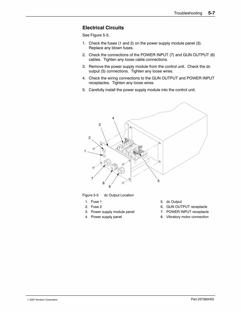
Electrical CircuitsSee Figure 5-5.
1. Check the fuses (1 and 2) on the power supply module panel (3).Replace any blown fuses.
2. Check the connections of the POWER INPUT (7) and GUN OUTPUT (6)cables. Tighten any loose cable connections.
3. Remove the power supply module from the control unit. Check the dcoutput (5) connections. Tighten any loose wires.
4. Check the wiring connections to the GUN OUTPUT and POWER INPUTreceptacles. Tighten any loose wires.
5. Carefully install the power supply module into the control unit.
3
4
1
7
6
5
2
8
Figure 5-5 dc Output Location
1. Fuse 12. Fuse 23. Power supply module panel4. Power supply panel
5. dc Output6. GUN OUTPUT receptacle7. POWER INPUT receptacle8. Vibratory motor connection

Troubleshooting5-8
Part 237395H03 � 2007 Nordson Corporation
Wiring Diagrams
FROM
MODULE
TO GUN
MODULECONTROLLER
MANIFOLD
2SOLSOL
1
GR
N/Y
EL
POWER SUPPLY MODULE
MANIFOLD MODULE CABINETGRN/YEL
GND
2.21k
GRN/YEL
NO.1
N
L65432
POWER HARNESS
332211
765432
765432
65432
GNDGND
GND
CONTROL HARNESS
SOLENOID 1SOLENOID 2POWDERPURGE
AUX
(FRONT VIEW)
POWERRECEPTACLE
BROWN
BLUE
BROWN
BLUE
LINE FILTER
FUSE BLOCK
FUSE
F2
F1
SWITCH
GRN/YEL
BLUE
BROWN
BLUE
BROWN
BLUE
BROWN
5
4
1
32
(FRONT VIEW)654
3 21 GUN
RECEPTACLE
DC POWER SUPPLY
GUN CONTROLLER MODULE
(ORANGE)
(RED(BLACK)DC COM
TRIGGER
+VDC OUT
(WHITE)(BLUE)(GREEN)GROUND
CURRENT FEEDBACKPURGE TRIGGER
(ORANGE)(BLACK)(RED)(WHITE)
(GREEN)(BLUE)
1
1
SK1SK2ORANGEBROWNBLUE
GRAYRED
BLACK 1
GRAYREDBROWNORANGEBLACKBLUE1
+12VDC
+24VDC+5VDC+5VDC24V COMDC COM
PURGE TRIGGER
TRIGGERDC COM+VDC OUTCURRENT FEEDBACK
N/CGROUND
J6
J4 (SOLENOID)
J5 (GUN)
N/CGNDCHASSIS
24V COM+24VDC+12VDCDC COM+5VDC+5VDC
(TRANSCEIVER)
J3
Figure 5-6 Wiring Diagram for Control Unit without Vibratory Motor Control

Troubleshooting 5-9
Part 237395H03� 2007 Nordson Corporation
Figure 5-7 Wiring Diagram for 115 Vac Control Unit with Vibratory Motor Control

Troubleshooting5-10
Part 237395H03 � 2007 Nordson Corporation
Wiring Diagrams (contd)
Figure 5-8 Wiring Diagram for 220 Vac Control Unit with Vibratory Motor Control

Repair 6-1
Part 237395H03� 2007 Nordson Corporation
Section 6Repair
WARNING: Allow only qualified personnel to perform the following tasks.Follow the safety instructions in this document and all other relateddocumentation.
WARNING: Disconnect and lock out electrical power before performing thefollowing tasks. Failure to observe this warning could result in personalinjury or death.
Keypad Module Replacement See Figure 6-1.
The keypad module (3) can be replaced from the front of the control unit.The keypad module consists of the LCD module, keypad, and three circuitboards that are plugged into each other and secured by standoffs.
CAUTION: The circuitry is sensitive to electrostatic discharge. Wear agrounding wrist strap when working on the control module. Failure toobserve this caution may result in damage to the keypad module.
1. Remove the four screws (1) and washers (2).
2. Tilt the top of the keypad module (3) forward and disconnect all threeconnectors (4).
3. Lift the keypad module out of the control unit.
4. Install the new bezel gasket on the new keypad module.
5. Place the new keypad module on the bottom edge of the opening andconnect all three connectors (4).
CAUTION: Special care must be taken when installing the keypad so to notdamage the gasket and cause it to bulge/deform and loose its seal.
6. Tilt the keypad module in and inspect the bezel gasket to make sure it isseated properly.
7. Carefully tighten the four screws in a criss-cross pattern to secure it tothe control unit. As you are tightening the screws, make sure the bezelgasket does not bulge or deform in any way.
8. Retighten screws as needed to close any air gaps that exist between thegasket and the cabinet.

Repair6-2
Part 237395H03 � 2007 Nordson Corporation
Keypad Module Replacement (contd)
12
3
4
Figure 6-1 Keypad Module Replacement
1. Screw2. Washer
3. Keypad module 4. Connectors

Repair 6-3
Part 237395H03� 2007 Nordson Corporation
DC Power Supply ReplacementSee Figure 6-2.
The dc power supply is mounted on the power supply module, which is thebottom left panel of the control unit.
1. Remove the four screws (2) securing the power supply module (1) to thecontrol unit (5).
2. Unplug the ac input (4) and dc output (6) connectors from the dc powersupply board (3).
3. Remove the four screws that secure the dc power supply board to thepower supply module. Remove the dc power supply board.
NOTE: If necessary, carefully use a screwdriver to unsnap the dc powersupply board from the standoffs.
4. Snap the new dc power supply board onto the four standoffs on thepower supply module.
5. Secure the new dc power supply board to the power supply moduleusing the four screws.
6. Attach the ac input and dc output connectors to the new dc powersupply board.
7. Secure the power supply module to the control unit using the fourscrews.
3
4
1
65
2
Figure 6-2 dc Power Supply Replacement
1. Power supply module2. Screws3. dc Power supply board
4. ac Input connector5. Control unit6. dc Output connector

Repair6-4
Part 237395H03 � 2007 Nordson Corporation
Manifold ReplacementSee Figure 6-3.
The manifold assembly is mounted on the pneumatic module, which isaccessible through the bottom right panel of the control unit.
NOTE: The pneumatic module components (such as the manifold) can bereplaced separately, and the solenoid valves can be rebuilt. Refer toSolenoid Valve Rebuild on page 6-6 and Service Kits on page 7-11.
1. Disconnect all air tubing from the control unit.
2. Remove the four screws (2) securing the manifold panel (6) to thebottom of the control unit (1).
3. Disconnect the air tubing from the manifold assembly (5).
4. Disconnect the ground wire from the manifold panel ground stud (3).
5. Separate the solenoid coils (7) from the manifold by removing theknurled nuts (9) and washers (8) and pulling off the coils.
6. Remove the two screws (4) securing the manifold assembly to themanifold panel.
7. Rebuild the solenoid valve, if necessary. Refer to Solenoid ValveRebuild on page 6-6 for instructions.
8. Secure the new manifold assembly to the manifold panel using the twoscrews.
9. Secure the solenoid coil to the solenoid valve using the washer andknurled nut.
10. Connect the ground wire to the ground stud on the manifold panel.
11. Connect the air tubing to the manifold assembly. See Figure 6-5 for apneumatic diagram.
12. Secure the pneumatic module to the control unit using the four screws.

Repair 6-5
Part 237395H03� 2007 Nordson Corporation
1
9
8
7
2
43
6
5
Figure 6-3 Manifold Replacement
1. Control unit2. Screws3. Ground stud4. Screws5. Manifold assembly
6. Manifold panel7. Solenoid coil8. Washer9. Knurled nut

Repair6-6
Part 237395H03 � 2007 Nordson Corporation
Solenoid Valve RebuildSee Figure 6-4.
This procedure uses the valve seal, trigger, or purge valve service kits torebuild the solenoid valves. Refer to Service Kits on page 7-11 for moreinformation.
NOTE: Seven tee seals are included in the seal kit. If you rebuild thetrigger valve, use all seven tee seals. If you rebuild the auxiliary valve, youwill only use six tee seals.
1. Remove the manifold. Refer to Manifold Replacement on page 6-4 forinstructions.
2. Remove the screws (7) and pull the end cap (6) off the solenoid valvebody (1). Make sure the three small O-rings (8) and flat roundgasket (9) remain in the end cap.
3. Remove the piston and bushing (5) from the valve body.
4. Push on the spring pad (2) to force the spool assembly (4) out of thevalve body.
5. Disassemble the spool assembly and clean and replace parts asnecessary.
6. Assemble the solenoid valve. Lightly lubricate the following items withthe lubricant included in the service kit before installing it them:
� spool (11)
� tee seals (10)
� piston (5) O-ring
� O-rings (8)
� gasket (9)
NOTE: The spacers (12) and tee seals (10) are identical and may beinstalled in any location along the spool (11). Use only six of the seventee seals provided in the seal kit when rebuilding the purge valve.
7. Install the spool assembly into the valve body.
8. Install the piston and bushing into the valve body.
9. Make sure that the small O-rings are aligned with the holes in the valvebody, and install the endcap using the four screws. Torque the screwsto 1 Nm (9 in.-lb).
Once the manifold is removed from the control unit, either of the spools canbe rebuilt. See Figure 6-5 to determine which valve to repair.

Repair 6-7
Part 237395H03� 2007 Nordson Corporation
1
2
5
3
6
7
4
889
12
1110
Figure 6-4 Solenoid Valve Rebuild
1. Valve body2. Spring pad3. Spring4. Spool assembly
5. Piston and bushing6. End cap7. Screw8. O-rings
9. Round gasket10. Tee seal11. Spool12. Spacer

Repair6-8
Part 237395H03 � 2007 Nordson Corporation
Regulator/Gauge ReplacementRemove the right front panel to access the regulator/gauges.
1. Remove the four screws securing the regulator/gauge module to thecontrol unit.
2. Lift the regulator/gauge module out of the control unit and disconnectthe air tubing from the regulator/gauge.
3. Pull the regulator cap off the regulator/gauge and unscrew the panelmounting ring. Remove the regulator/gauge from the panel.
4. Secure the new regulator/gauge to the panel using the mounting ring.Install the new regulator cap.
5. Connect the air tubing to the new regulator/gauge. See Figure 6-5 for apneumatic diagram.
CAUTION: A bezel gasket is included on the regulator assembly. Specialcare must be taken when installing the regulator so to not damage thegasket and cause it to bulge/deform and loose its seal.
6. Set the regulator/gauge module into the control unit and inspect thebezel gasket to make sure it is seated properly.
7. Carefully tighten the four screws in a criss-cross pattern to secure it tothe control unit. As you are tightening the screws, make sure the bezelgasket does not bulge or deform in any way.
8. Retighten screws as needed to close any air gaps that exist between thegasket and the cabinet.

Repair 6-9
Part 237395H03� 2007 Nordson Corporation
Figure 6-5 Pneumatic Diagram

Repair6-10
Part 237395H03 � 2007 Nordson Corporation

Parts 7-1
Part 237395H03� 2007 Nordson Corporation
Section 7Parts
Introduction To order parts, call the Finishing Customer Support Center at (800)433-9319 or contact your local Nordson representative.
Using the Illustrated Parts List Numbers in the Item column correspond to numbers that identify parts inillustrations following each parts list. The code NS (not shown) indicatesthat a listed part is not illustrated. A dash (—) is used when the part numberapplies to all parts in the illustration.
The number in the Part column is the Nordson Corporation part number. Aseries of dashes in this column (- - - - - -) means the part cannot be orderedseparately.
The Description column gives the part name, as well as its dimensions andother characteristics when appropriate. Indentions show the relationshipsbetween assemblies, subassemblies, and parts.
� If you order the assembly, items 1 and 2 will be included.
� If you order item 1, item 2 will be included.
� If you order item 2, you will receive item 2 only.
The number in the Quantity column is the quantity required per unit,assembly, or subassembly. The code AR (As Required) is used if the partnumber is a bulk item ordered in quantities or if the quantity per assemblydepends on the product version or model.
Letters in the Note column refer to notes at the end of each parts list. Notescontain important information about usage and ordering. Special attentionshould be given to notes.
Item Part Description Quantity Note— 0000000 Assembly 11 000000 � Subassembly 2 A2 000000 � � Part 1

Parts7-2
Part 237395H03 � 2007 Nordson Corporation
Control UnitSee Figure 7-1.
Item Part Description Quantity Note— 1018181 CONTROL UNIT, manual, 3 gauge, Sure Coat,
packaged1
1 322404 � SWITCH, rocker, DPST, dust tight 12 307372 � GASKET, front panel 23 982825 � SCREW, pan, recessed, M4 x 12, with integral
lock washer bezel16
4 327744 � KIT, keypad assembly, Sure Coat, manual 1 A5 1018246 � MODULE, gauge/regulator, Sure Coat, manual
controller1 A
6 1063284 � KIT, module, manifold, 3 gauge, manual, Sure Coat
1 A
7 335449 � POWER SUPPLY MODULE KIT, manualindividual controller
1 A
8 240674 � TAG, ground 39 983021 � WASHER, flat, e, 0.203 x 0.406 x 0.040 in.,
brass3
10 983401 � LOCK WASHER, m, split, M5, steel, zinc 311 984702 � NUT, hex, M5, brass 312 302189 � WIRE, ground, assembly, 10.50 in. 2NS 972286 � REDUCER, 8-mm stem x 6-mm tube 2NS 900742 � TUBING, polyurethane, 6 mm, blue ARNS 240976 � CLAMP, ground, with wire 1 BNS - - - - - - � RESISTOR, 2.2k, 0.25 W, 1% axl 1 CNS 982499 � SCREW, pan, slotted, M6 x 12, zinc 4NS 983128 � LOCK WASHER, m, internal, M6, steel, zinc 4NS 173086 � CABLE, power, 3 wire, 18 ft 1
NOTE A: The parts included in these assemblies are identified later in this section.
B: This is the external ground assembly that connects the control unit to a true earth ground.
C: This resistor is located on the keypad module plug in connector J4.
AR: As Required
NS: Not Shown

Parts 7-3
Part 237395H03� 2007 Nordson Corporation
POWER
1
INPUT: 85−250VAC 50−60 Hz,/1Ø, 2 AMP
GUN OUTPUTPOWER INPUT
F1 2A250VAC
F2 2A250VAC
8
73
2 3543
6 3
91011
9
12
8
1011
Figure 7-1 Control Unit

Parts7-4
Part 237395H03 � 2007 Nordson Corporation
Keypad ModuleSee Figure 7-2.
Item Part Description Quantity Note— 327744 KIT, keypad assembly, Sure Coat, manual 1— - - - - - - � MODULE, keypad, Sure Coat 11 288836 � � MODULE, LCD, Sure Coat 12 288839 � � PANEL, keypad, manual control,
Sure Coat1
3 227186 � � PCA, manual gun controller 14 227210 � � � FUSE, submini, 40 mA, 250 V, trigger 15 227210 � � � FUSE, submini, 40 mA, 250 V, purge 1
NS 288814 � BEZEL, manual control, Sure Coat 1NS 982825 � SCREW, panel, recessed, M4 x 12, with
integral lock washer bezel4
NS 307916 UPGRADE KIT, software, manual gun control unit 1 ANOTE A: Order this kit to upgrade your control unit to the most current software version.
NS: Not Shown

Parts 7-5
Part 237395H03� 2007 Nordson Corporation
3
1
2
4
5
Figure 7-2 Keypad Module
Parts7-6
Part 237395H03 � 2007 Nordson Corporation
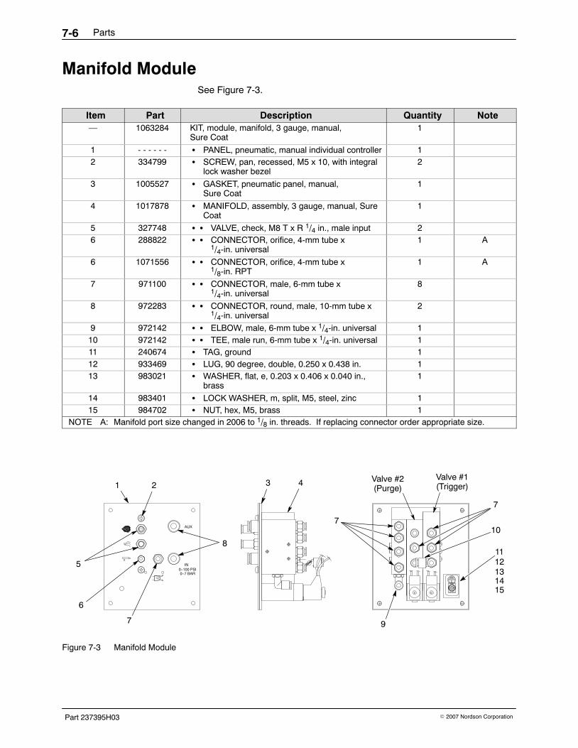
Manifold Module See Figure 7-3.
Item Part Description Quantity Note— 1063284 KIT, module, manifold, 3 gauge, manual,
Sure Coat1
1 - - - - - - � PANEL, pneumatic, manual individual controller 12 334799 � SCREW, pan, recessed, M5 x 10, with integral
lock washer bezel2
3 1005527 � GASKET, pneumatic panel, manual, Sure Coat
1
4 1017878 � MANIFOLD, assembly, 3 gauge, manual, SureCoat
1
5 327748 � � VALVE, check, M8 T x R 1/4 in., male input 26 288822 � � CONNECTOR, orifice, 4-mm tube x
1/4-in. universal1 A
6 1071556 � � CONNECTOR, orifice, 4-mm tube x1/8-in. RPT
1 A
7 971100 � � CONNECTOR, male, 6-mm tube x1/4-in. universal
8
8 972283 � � CONNECTOR, round, male, 10-mm tube x1/4-in. universal
2
9 972142 � � ELBOW, male, 6-mm tube x 1/4-in. universal 110 972142 � � TEE, male run, 6-mm tube x 1/4-in. universal 111 240674 � TAG, ground 112 933469 � LUG, 90 degree, double, 0.250 x 0.438 in. 113 983021 � WASHER, flat, e, 0.203 x 0.406 x 0.040 in.,
brass1
14 983401 � LOCK WASHER, m, split, M5, steel, zinc 115 984702 � NUT, hex, M5, brass 1
NOTE A: Manifold port size changed in 2006 to 1/8 in. threads. If replacing connector order appropriate size.
6
5
7
1 2 43
11
9
10
7
8
12131415
7
Valve #2(Purge)
Valve #1(Trigger)
0−7 BAR0−100 PSI
IN
AUX
Figure 7-3 Manifold Module

Parts 7-7
Part 237395H03� 2007 Nordson Corporation
Power Supply Module See Figure 7-4.
Item Part Description Quantity Note335449 POWER SUPPLY MODULE KIT, manual individual
controller (standard version)
- - - - - - POWER SUPPLY MODULE,manual individualcontroller, 115V, with vibratory motor control
- - - - - - POWER SUPPLY MODULE,manual individualcontroller, 220V, with vibratory motor control
1 982824 � SCREW, pan, recessed, M3 x 8, with integrallock washer bezel
4
2 1067030 � FILTER, line, with butt splice 13 982825 � SCREW, pan head, recessed, M4 x 12, with
integral lock washer bezel2
4 288803 � POWER SUPPLY, 24, 5, 12 Vdc, 40 W 15 335442 � HARNESS, control, manual individual
controller1
6 939122 � SEAL, conduit fitting, 1/2 in. 27 984526 � NUT, lock, 1/2-in. conduit 28 288841 � RECEPTACLE, input, T wire, female 19 - - - - - - � PANEL, power supply tray 110 302195 � GASKET, back panel, electrostatic,
Sure Coat1
11 131477 � FUSE, 2.00, fast acting, 250 V, 5 x 20 212 288804 � FUSE HOLDER, panel mount, 5 x 20 213 288842 � RECEPTACLE, power, Sure Coat 114 271221 � LUG, 45, double, 0.250 in. x 0.438 in. 115 983401 � LOCK WASHER, m, split, M5, stainless steel,
zinc1
16 983021 � WASHER, flat, e, 0.203 x 0.406 x 0.040 in.,brass
1
17 984702 � NUT, hex, M5, brass 118 1068173 � RELAY, two-pole, 30 amp 1 A19 1068172 � CAPACITOR, film, type 7124, 2.5 f 1 B
NOTE A: Use only with control units with vibratory motor control.
B: Use only with 110 Vac Sure Coat control units with vibratory motor control.

Parts7-8
Part 237395H03 � 2007 Nordson Corporation
Power Supply Module (contd)
1
4
6713
5
678
910
151617
1112
14
2
3
19
18
Figure 7-4 Power Supply Module

Parts 7-9
Part 237395H03� 2007 Nordson Corporation
Gauge/Regulator Module See Figure 7-5.
Item Part Description Quantity Note— 1018246 GAUGE/REGULATOR MODULE, Sure Coat,
manual controller1
1 288817 � PANEL, manual controller, 3 gauge, Sure Coat
1
2 288814 � BEZEL, manual controller, Sure Coat 13 141603 � SEAL, panel, regulator 34 1004625 � REGULATOR ASSEMBLY, 0−100 psi, 0−7 bar,
vertical2
5 1018157 � REGULATOR ASSEMBLY, 0−25 psi, 0−1.7 bar,vertical
1
PUSH TO LOCK PUSH TO LOCK PUSH TO LOCK
2
1
54
3
Figure 7-5 Gauge/Regulator Module

Parts7-10
Part 237395H03 � 2007 Nordson Corporation
Mounting Bracket KitsSee Figure 7-6.
Item Part Description Quantity Note1 288828 BRACKET KIT, mounting, rail 12 1023868 WALL MOUNT KIT, manual, Sure Coat 13 288844 TABLE TOP BRACKET KIT, Sure Coat 1
1
3
2
Figure 7-6 Mounting Bracket Kits
Parts 7-11
Part 237395H03� 2007 Nordson Corporation
Air TubingOrder all air tubing in increments of one foot.
Part Description Note900618 TUBING, polyurethane, 8 mm, blue900619 TUBING, polyurethane, 8 mm, black900742 TUBING, polyurethane, 6 mm, blue900741 TUBING, polyurethane, 6 mm, black
Service KitsSee Figure 7-3 to determine which valve to order.
Item Part Description Quantity NoteNS 333677 TRIGGER VALVE SERVICE KIT 1 ANS 333678 PURGE (auxiliary) VALVE SERVICE KIT 1 BNS 900349 LUBRICANT, PTFE grease, 0.750-oz tube 1 CNS 1027108 SEAL SERVICE KIT, spool, valve 1 D
NOTE A: The trigger valve is the longer of the two valves.
B: The purge valve is the shorter of the two valves.
C: Lubricate the spool with this grease when you rebuild either of the valves.
D: The valve spool seal service kit, part 1027108, contains seven tee seals. This kit may be used to rebuildeither the trigger or purge valve. If you use the seal kit to rebuild the purge valve, only six tee seals will beused. Discard the extra tee seal.
NS: Not Shown
Cable AdapterUse this cable adapter to connect a Versa-Spray or Tribomatic 500 spraygun to the Sure Coat manual gun control unit.
Part Description Note339783 CABLE ADAPTER, Versa-Spray to Sure Coat, manual305776 CABLE ADAPTER, Tribomatic to Sure Coat, manual

Parts7-12
Part 237395H03 � 2007 Nordson Corporation