Supporting information - rsc.org · Supporting information Graphene Growth under Knudsen Molecular...
10
Supporting information Graphene Growth under Knudsen Molecular Flow on Confined Catalytic Metal Coil Hyojin Bong † , Sae Byeok Jo † , Boseok Kang, Seong Kyu Lee, Hyun Ho Kim, Seunggoo Lee, Kilwon Cho* [ † ] H.Bong and S.B. Jo contributed equally to this work. Send correspondence to Kilwon Cho ([email protected]), Department of Chemical Engineering, Pohang University of Science and Technology, Pohang 790-784, Korea. Electronic Supplementary Material (ESI) for Nanoscale. This journal is © The Royal Society of Chemistry 2014
Transcript of Supporting information - rsc.org · Supporting information Graphene Growth under Knudsen Molecular...

Supporting information
Graphene Growth under Knudsen Molecular Flow on Confined Catalytic
Metal Coil
Hyojin Bong†, Sae Byeok Jo†, Boseok Kang, Seong Kyu Lee, Hyun Ho Kim, Seunggoo Lee, Kilwon
Cho*
[†] H.Bong and S.B. Jo contributed equally to this work.
Send correspondence to
Kilwon Cho ([email protected]),
Department of Chemical Engineering, Pohang University of Science and Technology,
Pohang 790-784, Korea.
Electronic Supplementary Material (ESI) for Nanoscale.This journal is © The Royal Society of Chemistry 2014

Relative diffusivity of confined system
Diffusivity of gases, in the open non-stacked system, (DA) is defined as,1
𝐷𝐴=𝜆3
8𝑘𝐵𝐾
𝜋𝑀𝐴
where,
= mean free path
kB = Boltzmann constant,
K = thermodynamic temperature,
MA = molecular weight of gas.
For Knudsen diffusion, should be replaced with system dimension, L. The relative diffusivity of confined system of gases (DK) can now be defined as,
𝐷𝐾=𝐿3
8𝑘𝐵𝐾
𝜋𝑀𝐴=𝐷𝐴𝐾𝑛
where,
L = gap size
Kn = / L = Knudsen number.
1 Welty, James R. Wicks, Charles E. Wilson, Robert E. Rorrer, Gregory L. (2008). Fundamentals of
Momentum, Heat and Mass Transfer (5th ed.). Hoboken: John Wiley and Sons.

Table S1. Calculated Knudsen number (Kn = /L, = 119 μm) at various gap sizes, and flow regimes according to Knudsen number.
Gap size (L) Kn Flow regime
135 nm (stack) 881.5585 nm 203.4
Free molecular flow(Kn > 10)
30 m 3.53600 m 0.18
Transition flow(0.1 < Kn < 10)
1.2 mm 0.09 Slip flow(0.001 < Kn < 0.1)

Figure S1. Statistical distribution and Raman 2D-mapping (I2D/IG and ID/IG area 400 m2) of
the graphene films obtained from the multi-layer stacked substrates, 1st, 3rd, and 5th layers.

Figure S2. Raman spectra of the graphene films obtained (a) ~ (e) from the stacked systems
and (c’) ~ (e’) from the non-stacked system on the SiO2/Si substrates.

4.76 vol% 7.69 vol%CH4 concentration
Mono-layer Bi-layer Mono-layer Bi-layer
Stacked system 25.3 % 51.4 % 18.9 % 35.5 %
Non-stacked system 22.1 % 42.1 % 19.3 % 31.0 %
Figure S3. The Raman mapping images of the graphene films (I2D/IG ratio, area 100 m2). (a)
CH4 concentrations are 4.76 and 7.69 vol% in the stacked system. (b) CH4 concentrations are
4.76 and 7.69 vol% in the non-stacked system. Table shows the percentages of the monolayer
and bi-layer parts obtained from each graphene film.
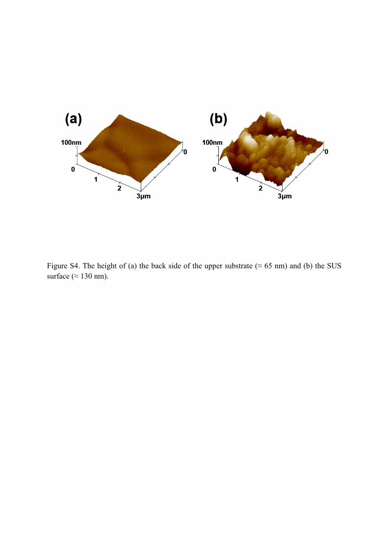
Figure S4. The height of (a) the back side of the upper substrate (≈ 65 nm) and (b) the SUS surface (≈ 130 nm).

Gap size135 nm
(stacked system)30 m 1.2 mm
Non-stackedsystem
RMS 8.7 nm 17.4 nm 24.1 nm 23.8 nm
Max. height 69.7 nm 137.2 nm 170.3 nm 270.9 nm
Figure S5. AFM images of heat-treated Ni surfaces under a H2/Ar atmosphere for various gap
sizes of (a) 135 nm (stacked system), (b) 30 m, and (c) 1.2 mm.

Figure S6. Demonstration of graphene-based large area flexible transparent conducting films
(TCFs) and flexible OFETs. (a) Photographs of (left) flexible TCFs (8cm × 3cm) and (right)
pentacene-based OFET array on flexible PAR substrates using pattern-transferred graphene
as source/drain electrodes. Inset shows optical image of graphene electrode (L = 50 μm, W =
200 μm). (b) Output characteristics and (c) transfer characteristics of OFETs. Inset in (b)
shows schematic diagram of a cross section of FETs.
For flexible TCF demonstrations, 8 cm × 3 cm (width × length) Ni/SUS film was roll-
stacked to give a catalytic coil with dimension of 1 cm × 3 cm (diameter × length) as shown
in Figure S5a. The graphene was synthesized under CH4 concentration of 1.64 vol% on the
roll-stacked coil in a closed CVD chamber and then was transferred to PAR substrate by

conventional wet-transfer method as described in the experimental section. The average RS of
TCF was 1.51 ± 0.29 kΩ/sq.
Pentacene-based OFETs were characterized by measuring the output and transfer
characteristics of the devices, as shown in Figure S5b ~ c. The transfer characteristics were
used to calculate the field-effect mobility in the saturation regime using the relationship,
𝐼𝐷𝑆=𝜇𝐶𝑖𝑊
2𝐿(𝑉𝐺𝑆 ‒ 𝑉𝑡ℎ)
2
where W and L are the channel width and length, respectively, Ci is the specific
capacitance of the gate dielectric, and μ is the field-effect mobility. The average field-effect
mobilities obtained from the transfer curve were 0.51 cm2 /Vs and the device showed high
mechanical stability.
Fabrication of organic field effect transistor (OFET): Graphene electrode based OFET
devices were built on flexible plastic substrates using polyarylate (PAR, Ferrania
Technologies). A gate electrode was spin-casted onto the PAR films using a water-based ink
of the conducting polymer that is poly(3,4-ethylenedioxythiophene) doped with polystyrene
sulfonic acid (PEDOT/PSS, Baytron P from Bayer AG). Then, a gate dielectric was deposited
by spin-casting onto the PAR film using a mixture of poly-4-vinylphenol (PVP, Mw =20,000
g/mol) and poly(melamine-co-formaldehyde), methylated (PMF, Mw = 511 g/mol) in
dimethylformamide solution. The film was heat-treated to cross-link the gate dielectric layer
for 1 h at 180 oC in a vacuum oven. UV lithography method was used for patterning the
graphene films as source/drain electrodes. By etching RIE plasma (250W, 60s), the patterned
graphene electrodes were fabricated and had the defined channel lengths and widths as L =
30, 50 m; W = 200 m. Finally, 50 nm thick pentacene as an active layer for OFETs were
thermally evaporated onto the films under vacuum ( ~ 10-6 Torr).

![Supporting information 20170215 - rsc.org fileInjector temperature [°C] 100 100 100 100 Column ...](https://static.fdocuments.net/doc/165x107/5b946bf209d3f2df3f8cef83/supporting-information-20170215-rsc-temperature-c-100-100-100-100-column.jpg)