Superparamagnetic Materials - University of...
12
University of Ljubljana Faculty of Mathematics and Physics Seminar I b — 4th year (old program) Superparamagnetic materials Author: Miha Marolt † Advisor: Assoc. Prof. Dr. Zvonko Jagliˇ ci´ c Kranj, 23.4.2014 Abstract Properties and applications of superparamagnetic materials, i.e. materials composed of very small magnetic grains, are briefly presented. After a short introduction, theory describing a single idealised grain is laid out and some magnetic properties of superparamagnets (FC and ZFC curves, M (H) curve) are explained. There are many practical applications of superpara- magnetic materials. For example ferrofluids are used for liquid seals, efficient heat transfer and damping. Even more importantly, superparamagnetic materials play a major role in the hard disk drive technology. Various challenges related to thermal stability and writability stem from the ever decreasing size of magnetic grains. Currently four cutting edge HDD technologies that either sidestep or solve problems related to magnetic grains are being developed: heat-assisted magnetic recording, bit-patterned recording, shingled magnetic recording and helium filled HDDs. † E-mail address: [email protected]
Transcript of Superparamagnetic Materials - University of...
University of LjubljanaFaculty of Mathematics and Physics
Seminar Ib — 4th year (old program)
Superparamagnetic materials
Author: Miha Marolt†
Advisor: Assoc. Prof. Dr. Zvonko Jaglicic
Kranj, 23.4.2014
Abstract
Properties and applications of superparamagnetic materials, i.e. materials composed of verysmall magnetic grains, are briefly presented. After a short introduction, theory describing asingle idealised grain is laid out and some magnetic properties of superparamagnets (FC andZFC curves, M(H) curve) are explained. There are many practical applications of superpara-magnetic materials. For example ferrofluids are used for liquid seals, efficient heat transfer anddamping. Even more importantly, superparamagnetic materials play a major role in the harddisk drive technology. Various challenges related to thermal stability and writability stem fromthe ever decreasing size of magnetic grains. Currently four cutting edge HDD technologies thateither sidestep or solve problems related to magnetic grains are being developed: heat-assistedmagnetic recording, bit-patterned recording, shingled magnetic recording and helium filledHDDs.
† E-mail address: [email protected]
Contents
1 Introduction 1
2 Properties 22.1 A single grain . . . . . . . . . . 22.2 A superparamagnet . . . . . . . 3
2.2.1 ZFC and FC magnetiza-tion curves . . . . . . . 3
2.2.2 Size distribution . . . . 42.2.3 Magnetization curve
M(H) . . . . . . . . . . 4
3 Applications 53.1 Ferrofluids . . . . . . . . . . . . 5
3.1.1 Liquid seals . . . . . . . 63.1.2 Heat transfer . . . . . . 73.1.3 Damping . . . . . . . . 7
3.2 HDD . . . . . . . . . . . . . . . 73.2.1 Basic operation . . . . . 73.2.2 Details . . . . . . . . . . 73.2.3 Future . . . . . . . . . . 9
4 Conclusion 10
1 Introduction
Definition A material is superparamagneticif it is made of very small single-domainnon-interacting magnetic1 grains dispersed insome non-magnetic medium. How small isvery small depends on properties of magneticgrains. Typical value of their diameter is onthe order of 10 nm. Since properties of su-perparamagnetic materials depend crucially onthe spontaneous magnetic moment of magneticgrains, it is implicitly understood that temper-ature is below the Curie or Neel temperature
1In this seminar I use term magnetic in two differentbut related meanings. Sometimes I use it as a short-hand for “ferri- or ferro-magnetic” and sometimes I useit to signify a property of non-zero spontaneous mag-netization. The first meaning is used when I talk aboutmagnetic grains and the second one when I talk aboutmagnetic material on HDD platter.
TC of magnetic grains. It doesn’t make senseto talk about superparamagnetism above TC .
Origin of name Above the so called block-ing temperature TB, which is material andexperiment dependent (see Section 2.1), su-perparamagnet can be described by the sameequations (details in Section 2.2.3) that areused for ordinary paramagnet (ensemble ofnon-interacting magnetic moments µ with en-ergy E = −µB when put in magnetic field B),the only difference being that magnetic mo-ments of individual particles are much largerin the case of superparamagnet (single atomsvs. grains composed of 1000s of atoms). There-fore magnetization curve M(H) of a super-paramagnet is similar to that of a paramagnet,but much steeper (higher susceptibility). Thisis the reason for the name super-paramagnet.Below TB superparamagnet’s magnetizationcurve M(H) has hysteresis and is thus moresimilar to ferromagnet’s magnetization curve.
Occurrences and applications Super-paramagnetic materials play an important rolein many areas of technology. In this seminarI will take a closer look at superparamagneticmaterials in hard disk drives (HDDs) and atferrofluids.
• In hard disk drives information is storedby magnetizing small pieces of magneticmaterial on the platter. The former iscomposed of magnetic nanograins.
• Ferrofluids, which are a colloidal liquid ofnanoscale magnetic grains suspended in acarrier liquid, are used for liquid seals (e.g.in HDDs), efficient heat transfer (e.g. inloudspeakers), in suspension systems andin various medical applications. They alsolook nice when put into vicinity of a per-manent magnet (Figure 4).
1
Superparamagnetic materials are also foundin nature in various rocks and living organ-isms [1]. Some companies even sell magneticnanograins extracted from horse spleen (that isnot the primary way of production though) [2].
2 Properties
First we will take a look at the theory de-scribing a single magnetic grain. Then someproperties of superparamagnets will be pre-sented and explained in terms of properties ofa single grain.
2.1 A single grain
Let’s for the sake of simplicity assume thefollowing:
• Grain is composed of a single ferro- orferri-magnetic domain and its Curie orNeel temperature TC is higher than tem-perature we are observing the grain at.Both conditions are rather mild sincemany materials with domain sizes on theorder of µm � 10 nm and with TC �Troom exist.
• Grain has only uniaxial magneticanisotropy, which means that there aretwo easy directions of magnetization2
pointing in opposite directions. We needgrain with some magnetic anisotropy, sothat it can hold its magnetization, anduniaxial is the simplest one and it usuallydominates [2].
Energy of a single-domain magnetic grainwith uniaxial anisotropy in external magnetic
2Easy direction of magnetization is an energeticallyfavorable direction of spontaneous magnetization thatis determined by the magnetic anisotropy [4]. Whenanisotropy is uniaxial, there are two easy directions ofmagnetization that point in opposite directions alongthe easy axis.
field H is sum of its magnetic anisotropy andZeeman energies [18],
E = KV sin2(φ− θ)− µ0MsV H cosφ, (1)
where V is the volume of a grain, K is uni-axial anisotropy parameter and Ms is satura-tion magnetization. External magnetic fieldH, grain’s magnetization and easy axis of mag-netization all lay in the same plane. φ is the an-gle between magnetization and magnetic field,while θ is the angle between easy direction ofmagnetization and magnetic field.
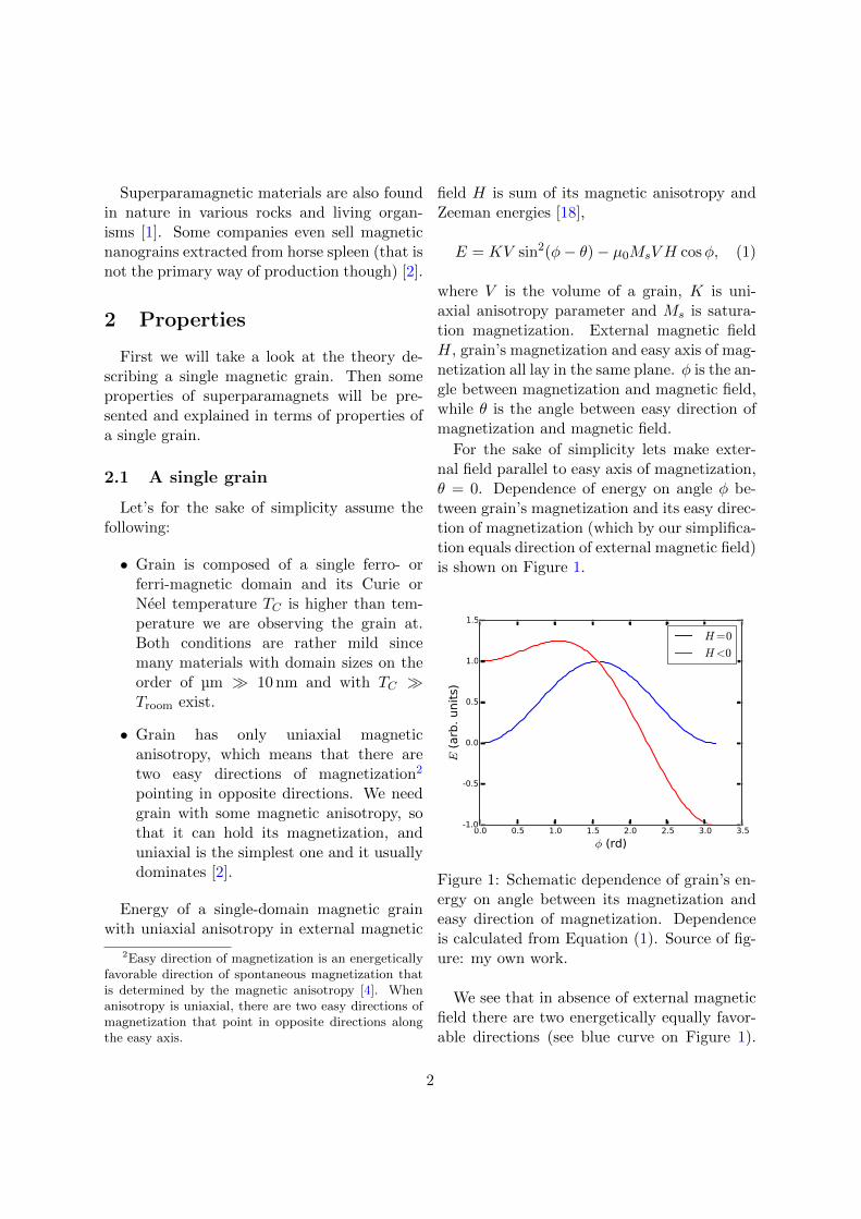
For the sake of simplicity lets make exter-nal field parallel to easy axis of magnetization,θ = 0. Dependence of energy on angle φ be-tween grain’s magnetization and its easy direc-tion of magnetization (which by our simplifica-tion equals direction of external magnetic field)is shown on Figure 1.
Figure 1: Schematic dependence of grain’s en-ergy on angle between its magnetization andeasy direction of magnetization. Dependenceis calculated from Equation (1). Source of fig-ure: my own work.
We see that in absence of external magneticfield there are two energetically equally favor-able directions (see blue curve on Figure 1).
2
They are both parallel to easy axis of magneti-zation and between them is energy barrier δEof size KV . If temperature is high enough,thermal energy kT can overcome the barrierand grain’s magnetization changes direction.
Non-zero magnetic field breaks the symme-try between the two magnetizations along theeasy axis (see red curve on Figure 1). Energyof a grain is lower when magnetization pointsalong the external magnetic field than when itpoints in the opposite direction. Also energybarrier for jumping from magnetization alongthe external field to magnetization opposite toexternal field is much bigger than for the re-verse.
The thermal fluctuations of the magneti-zation direction between the easy directionsare called superparamagnetic (Neel) relaxationand typical time between the flops τ is givenby the Neel-Brown expression
τ = τ0 eδEkT ,
where τ0 is usually between 10−12 s and 10−9 s.τ0 depends weakly on temperature and var-ious material parameters such as magneticanisotropy constant, particle volume and satu-ration magnetization. [2]
The measured magnetization of the grainwill depend crucially on the timescale texp ofthe experiment. If texp � τ , the magnetiza-tion will appear static, while if texp � τ , theaverage value will be measured (in absence ofexternal field this will be 0). In practice thetwo regimes are classified in terms of temper-ature instead of time. A blocking temperatureTB is defined [2]; it is the temperature at whichthe relaxation time τ equals the experimenttimescale texp. Note that the blocking temper-ature is not uniquely defined for a given ma-terial, because it depends on timescale texp ofthe experimental technique used.
2.2 A superparamagnet
In practice one usually deals with matterthat is composed of a large number of mag-netic grains. Let’s investigate some propertiesof such systems.
2.2.1 ZFC and FC magnetizationcurves
These two curves are noteworthy becauseit is easy to estimate two important prop-erties (blocking temperature and strength ofinteraction between particles) of a monodis-perse sample just by quickly looking at thegraphs of temperature dependence of suscep-tibility χ(T ).
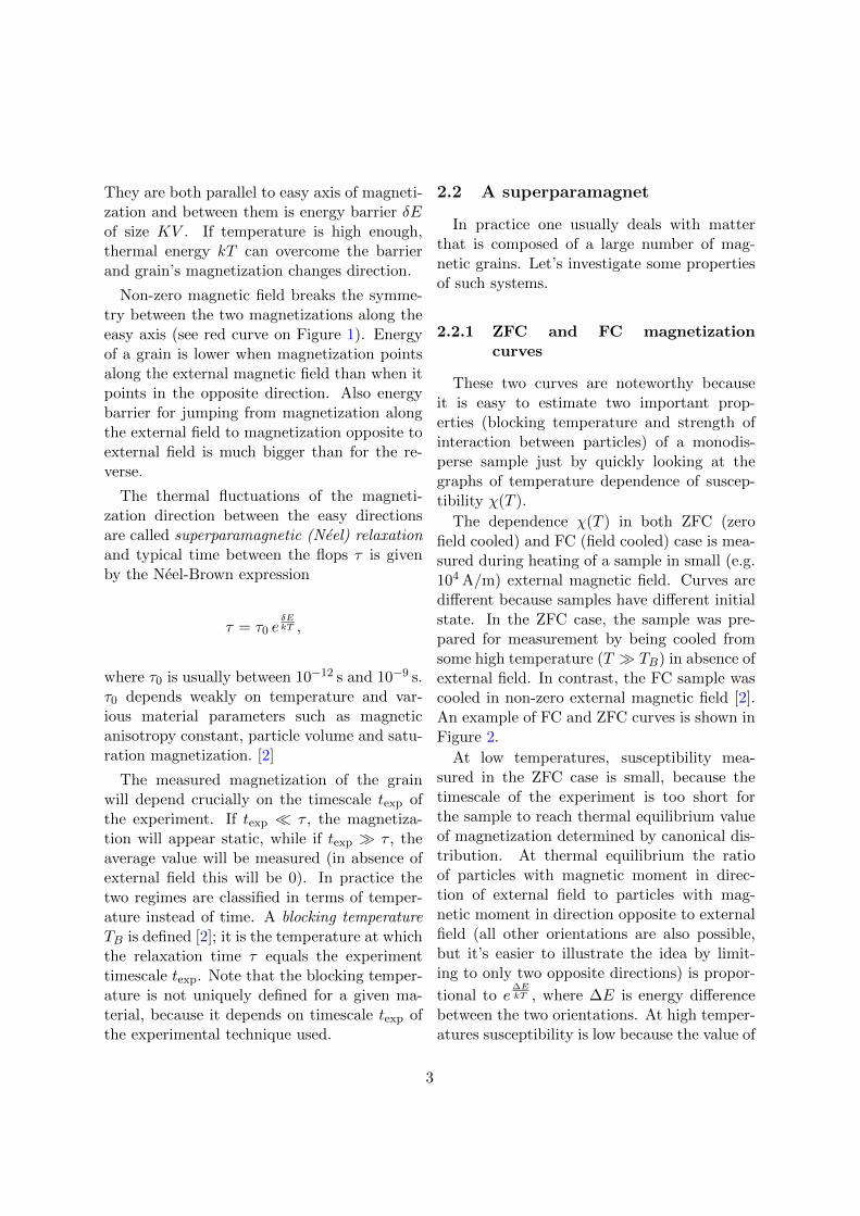
The dependence χ(T ) in both ZFC (zerofield cooled) and FC (field cooled) case is mea-sured during heating of a sample in small (e.g.104 A/m) external magnetic field. Curves aredifferent because samples have different initialstate. In the ZFC case, the sample was pre-pared for measurement by being cooled fromsome high temperature (T � TB) in absence ofexternal field. In contrast, the FC sample wascooled in non-zero external magnetic field [2].An example of FC and ZFC curves is shown inFigure 2.
At low temperatures, susceptibility mea-sured in the ZFC case is small, because thetimescale of the experiment is too short forthe sample to reach thermal equilibrium valueof magnetization determined by canonical dis-tribution. At thermal equilibrium the ratioof particles with magnetic moment in direc-tion of external field to particles with mag-netic moment in direction opposite to externalfield (all other orientations are also possible,but it’s easier to illustrate the idea by limit-ing to only two opposite directions) is propor-
tional to e∆EkT , where ∆E is energy difference
between the two orientations. At high temper-atures susceptibility is low because the value of
3
0 50 100 150 200 250 300 350
T (K)
0.5
1.0
1.5
2.0
2.5
3.0
3.5
χ(m
3kg−
1)
1e 5
FC
ZFC
Figure 2: ZFC and FC curves for sample ofmaghemite (γ−Fe2O3) magnetic grains withaverage diameter of 8 nm that are coated witholeic acid and dispersed in carnauba wax. Thedependant variable on the plot is mass suscep-tibility, χ = µ
mH . Mass fraction of maghemitegrains is 0.7 %. Blocking temperature can beestimated as the position of ZFC maximum —it’s about 46 K. Source of figure: my own work.
magnetization in thermal equilibrium is small
(again, proportional to e∆EkT ). The peak is
reached somewhere in between and it turns outthat maximum for a monodisperse sample is atTB.
The shape of FC curve is different from ZFCcurve below TB as during the cooling processin magnetic field the system has enough timeto reach equilibrium magnetization. Also itsshape for T < TB tells us how much interac-tion there is between grains. If the interac-tion is negligible, susceptibility will be approx-imately proportional to 1/T (Curie’s law) as inFigure 2, while if the interaction is large, sus-ceptibility will saturate at low temperatures.
2.2.2 Size distribution
In many applications, for example in HDDs,one wants grains as uniform in size as possi-ble. There are several methods to measure sizedistribution of a sample, for example observ-ing it under a transmission electron microscopeor measuring some macroscopic property (e.g.magnetization curve M(H)) of a sample andthen deriving the parameters of size distribu-tion based on physical models.
It turns out [2] that the log-normal distribu-tion,
f(V ) =1√
2πσVexp
(− ln2 (V/Vm)
2σ2
), (2)
is often a good model for magnetic grains.Vm is median grain volume and σ is standarddeviation of lnV . Sometimes log-normal distri-bution is used as volume-weighted distribution[3] and sometimes as number-weighted distri-bution [6][7]. In the first case f(V ) dV tellsproportion of entire magnetic volume taken bygrains of volumes between V and V +dV , whilein the second case f(V ) dV tells the ratio ofnumber of grains with volumes between V andV +dV and number of all grains in the sample.
The reason for log-normal size distributionis not completely understood yet [8].
2.2.3 Magnetization curve M(H)
Magnetization curves M(H) below andabove TB are qualitatively different. Here Iwill concentrate on curve for T > TB, becauseit can be used to calculate parameters of grainsize distribution.
• T > TB: In external magnetic field energydue to magnetic anisotropy is often muchsmaller than Zeeman energy, so energy ofa single grain (1) can be approximated asE = −µB+K V sin2(φ−θ) ≈ −µB. Letsfirst assume that all grains have magnetic
4
moments of the same size. Then we canuse the same theory as for Langevin para-magnetism. Because magnetic momentsof grains are much larger than magneticmoments of individual atoms, we use clas-sical limit: Brillouin function can be re-placed by Langevin function and the av-erage magnetization is given by [2]
M = M0 L(x) = M0
[cothx− 1
x
],
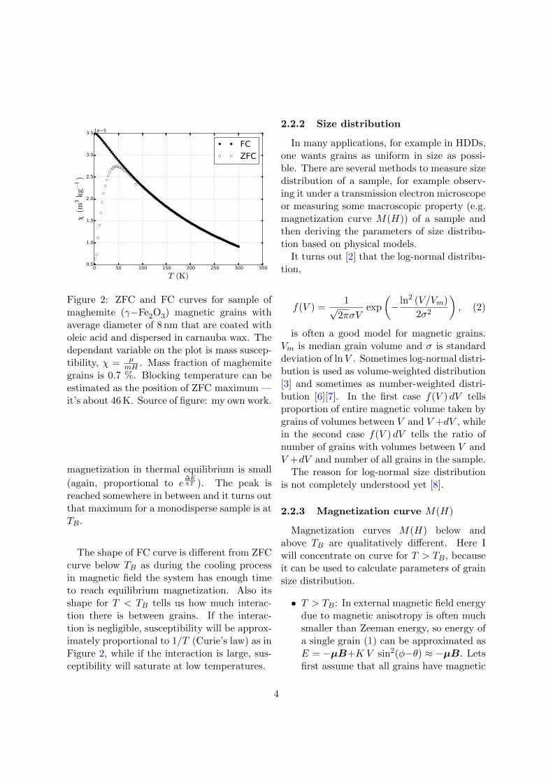
where x = µBk T . We see that the bigger
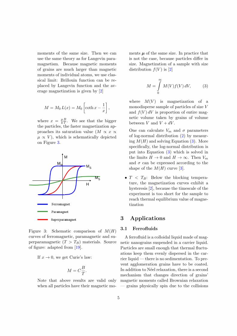
the particles, the faster magnetization ap-proaches its saturation value (M ∝ x ∝µ ∝ V ), which is schematically depictedon Figure 3.
Figure 3: Schematic comparison of M(H)curves of ferromagnetic, paramagnetic and su-perparamagnetic (T > TB) materials. Sourceof figure: adapted from [19].
If x→ 0, we get Curie’s law:
M = CB
T.
Note that above results are valid onlywhen all particles have their magnetic mo-
ments µ of the same size. In practice thatis not the case, because particles differ insize. Magnetization of a sample with sizedistribution f(V ) is [2]
M =
∞∫0
M(V )f(V ) dV, (3)
where M(V ) is magnetization of amonodisperse sample of particles of size Vand f(V ) dV is proportion of entire mag-netic volume taken by grains of volumebetween V and V + dV .
One can calculate Vm and σ parametersof log-normal distribution (2) by measur-ing M(H) and solving Equation (3). Morespecifically, the log-normal distribution isput into Equation (3) which is solved inthe limits H → 0 and H → ∞. Then Vmand σ can be expressed according to theshape of the M(H) curve [3].
• T < TB: Below the blocking tempera-ture, the magnetization curves exhibit ahysteresis [2], because the timescale of theexperiment is too short for the sample toreach thermal equilibrium value of magne-tization
3 Applications
3.1 Ferrofluids
A ferrofluid is a colloidal liquid made of mag-netic nanograins suspended in a carrier liquid.Particles are small enough that thermal fluctu-ations keep them evenly dispersed in the car-rier liquid — there is no sedimentation. To pre-vent agglomeration grains have to be coated.In addition to Neel relaxation, there is a secondmechanism that changes direction of grains’magnetic moments called Brownian relaxation— grains physically spin due to the collisions
5
with surrounding particles. In the followingparagraphs I briefly describe some practical ap-plications of ferrofluids. [20][21]
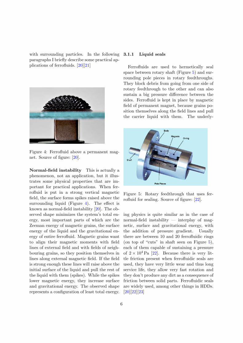
Figure 4: Ferrofluid above a permanent mag-net. Source of figure: [20].
Normal-field instability This is actually aphenomenon, not an application, but it illus-trates some physical properties that are im-portant for practical applications. When fer-rofluid is put in a strong vertical magneticfield, the surface forms spikes raised above thesurrounding liquid (Figure 4). The effect isknown as normal-field instability [20]. The ob-served shape minimizes the system’s total en-ergy, most important parts of which are theZeeman energy of magnetic grains, the surfaceenergy of the liquid and the gravitational en-ergy of entire ferrofluid. Magnetic grains wantto align their magnetic moments with fieldlines of external field and with fields of neigh-bouring grains, so they position themselves inlines along external magnetic field. If the fieldis strong enough these lines will raise above theinitial surface of the liquid and pull the rest ofthe liquid with them (spikes). While the spikeslower magnetic energy, they increase surfaceand gravitational energy. The observed shaperepresents a configuration of least total energy.
3.1.1 Liquid seals
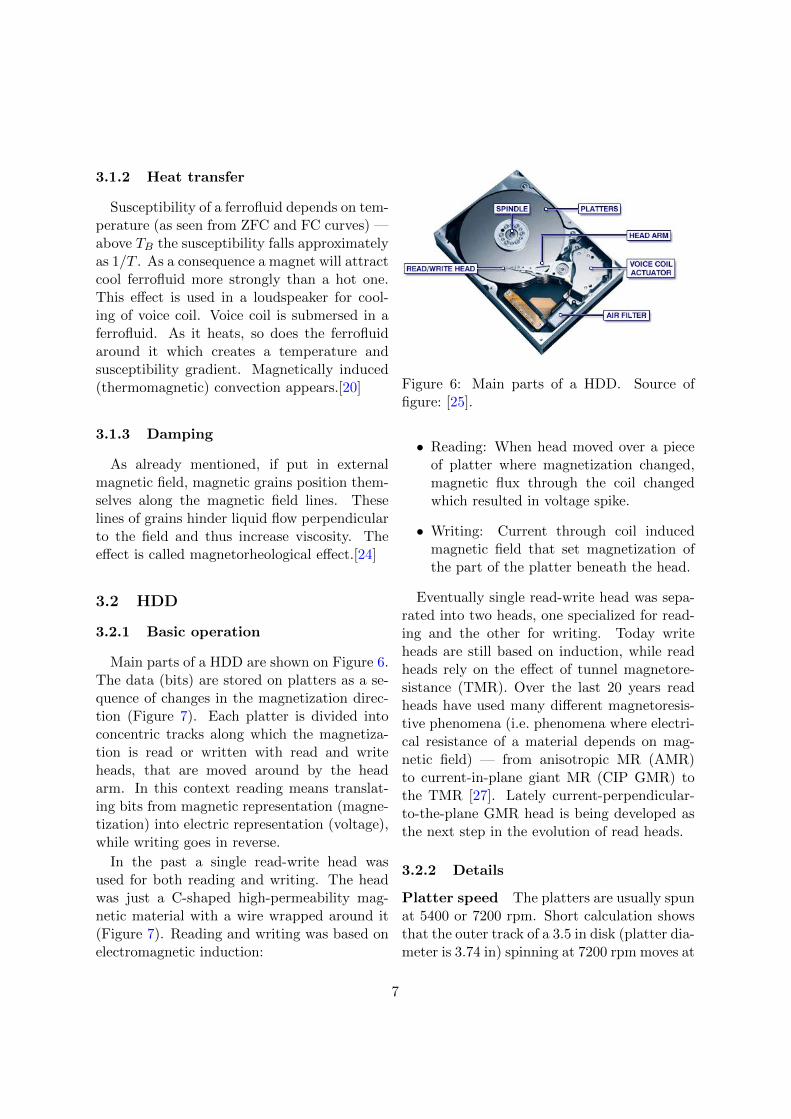
Ferrofluids are used to hermetically sealspace between rotary shaft (Figure 5) and sur-rounding pole pieces in rotary feedthroughs.They block debris from going from one side ofrotary feedthrough to the other and can alsosustain a big pressure difference between thesides. Ferrofluid is kept in place by magneticfield of permanent magnet, because grains po-sition themselves along the field lines and pullthe carrier liquid with them. The underly-
Figure 5: Rotary feedthrough that uses fer-rofluid for sealing. Source of figure: [22].
ing physics is quite similar as in the case ofnormal-field instability — interplay of mag-netic, surface and gravitational energy, withthe addition of pressure gradient. Usuallythere are between 10 and 20 ferrofluidic rings(on top of “cuts” in shaft seen on Figure 5),each of them capable of sustaining a pressureof 2× 10⁴ Pa [22]. Because there is very lit-tle friction present when ferrofluidic seals areused, they have very little wear and thus longservice life, they allow very fast rotation andthey don’t produce any dirt as a consequence offriction between solid parts. Ferrofluidic sealsare widely used, among other things in HDDs.[20][22][23]
6
3.1.2 Heat transfer
Susceptibility of a ferrofluid depends on tem-perature (as seen from ZFC and FC curves) —above TB the susceptibility falls approximatelyas 1/T . As a consequence a magnet will attractcool ferrofluid more strongly than a hot one.This effect is used in a loudspeaker for cool-ing of voice coil. Voice coil is submersed in aferrofluid. As it heats, so does the ferrofluidaround it which creates a temperature andsusceptibility gradient. Magnetically induced(thermomagnetic) convection appears.[20]
3.1.3 Damping
As already mentioned, if put in externalmagnetic field, magnetic grains position them-selves along the magnetic field lines. Theselines of grains hinder liquid flow perpendicularto the field and thus increase viscosity. Theeffect is called magnetorheological effect.[24]
3.2 HDD
3.2.1 Basic operation
Main parts of a HDD are shown on Figure 6.The data (bits) are stored on platters as a se-quence of changes in the magnetization direc-tion (Figure 7). Each platter is divided intoconcentric tracks along which the magnetiza-tion is read or written with read and writeheads, that are moved around by the headarm. In this context reading means translat-ing bits from magnetic representation (magne-tization) into electric representation (voltage),while writing goes in reverse.
In the past a single read-write head wasused for both reading and writing. The headwas just a C-shaped high-permeability mag-netic material with a wire wrapped around it(Figure 7). Reading and writing was based onelectromagnetic induction:
Figure 6: Main parts of a HDD. Source offigure: [25].
• Reading: When head moved over a pieceof platter where magnetization changed,magnetic flux through the coil changedwhich resulted in voltage spike.
• Writing: Current through coil inducedmagnetic field that set magnetization ofthe part of the platter beneath the head.
Eventually single read-write head was sepa-rated into two heads, one specialized for read-ing and the other for writing. Today writeheads are still based on induction, while readheads rely on the effect of tunnel magnetore-sistance (TMR). Over the last 20 years readheads have used many different magnetoresis-tive phenomena (i.e. phenomena where electri-cal resistance of a material depends on mag-netic field) — from anisotropic MR (AMR)to current-in-plane giant MR (CIP GMR) tothe TMR [27]. Lately current-perpendicular-to-the-plane GMR head is being developed asthe next step in the evolution of read heads.
3.2.2 Details
Platter speed The platters are usually spunat 5400 or 7200 rpm. Short calculation showsthat the outer track of a 3.5 in disk (platter dia-meter is 3.74 in) spinning at 7200 rpm moves at
7
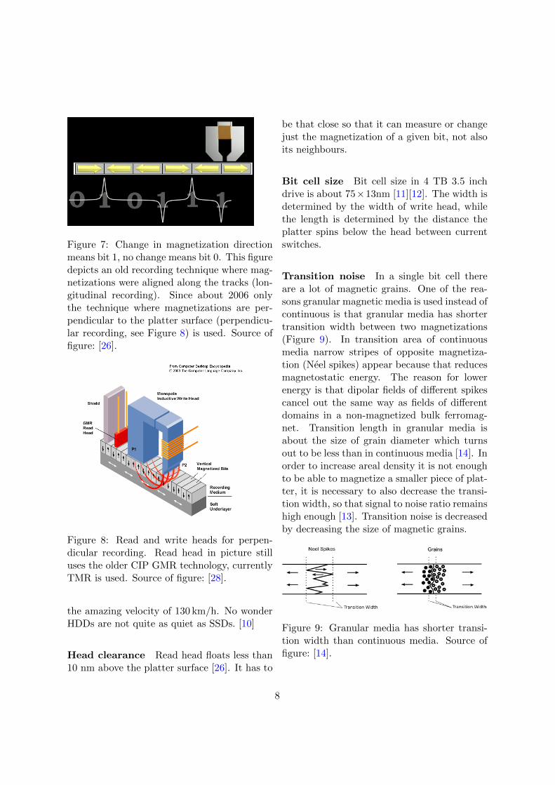
Figure 7: Change in magnetization directionmeans bit 1, no change means bit 0. This figuredepicts an old recording technique where mag-netizations were aligned along the tracks (lon-gitudinal recording). Since about 2006 onlythe technique where magnetizations are per-pendicular to the platter surface (perpendicu-lar recording, see Figure 8) is used. Source offigure: [26].
Figure 8: Read and write heads for perpen-dicular recording. Read head in picture stilluses the older CIP GMR technology, currentlyTMR is used. Source of figure: [28].
the amazing velocity of 130 km/h. No wonderHDDs are not quite as quiet as SSDs. [10]
Head clearance Read head floats less than10 nm above the platter surface [26]. It has to
be that close so that it can measure or changejust the magnetization of a given bit, not alsoits neighbours.
Bit cell size Bit cell size in 4 TB 3.5 inchdrive is about 75×13nm [11][12]. The width isdetermined by the width of write head, whilethe length is determined by the distance theplatter spins below the head between currentswitches.
Transition noise In a single bit cell thereare a lot of magnetic grains. One of the rea-sons granular magnetic media is used instead ofcontinuous is that granular media has shortertransition width between two magnetizations(Figure 9). In transition area of continuousmedia narrow stripes of opposite magnetiza-tion (Neel spikes) appear because that reducesmagnetostatic energy. The reason for lowerenergy is that dipolar fields of different spikescancel out the same way as fields of differentdomains in a non-magnetized bulk ferromag-net. Transition length in granular media isabout the size of grain diameter which turnsout to be less than in continuous media [14]. Inorder to increase areal density it is not enoughto be able to magnetize a smaller piece of plat-ter, it is necessary to also decrease the transi-tion width, so that signal to noise ratio remainshigh enough [13]. Transition noise is decreasedby decreasing the size of magnetic grains.
Figure 9: Granular media has shorter transi-tion width than continuous media. Source offigure: [14].
8
Bit stability Magnetic grains must be ableto hold magnetization that was given to themduring writing for a very long time in ordernot to loose information. A typical value ofenergy barrier δE = KV at room temperatureis between 70 kT and 100 kT [13]. From firstterm in Equation (1) we can see that if en-ergy barrier is to remain the same at decreas-ing grain volumes, anisotropy constant K hasto be increased. Engineers succeeded in pro-ducing grains with ever increasing anisotropyconstants, but problems started to appear atthe writing side. In order to switch magneti-zation direction of a grain, external magneticfield must remove the energy barrier and makecurrent direction the maximum and desired di-rection the minimum of energy (1) (see Fig-ure 1 to see effect of external magnetic fieldon energy). Field needed for this can be cal-culated by demanding a global maximum ofenergy E at current magnetization direction,φ = 0,
∂E
∂φ
∣∣∣φ=0
= 0 and∂2E
∂φ2
∣∣∣φ=0
< 0.
One can roughly estimate the field neededto change the magnetization by equating Zee-man energy and energy barrier in absence ofexternal field, µ0MsV H = KV . We get
H ≈ K
µ0Ms
As the anisotropy constant grows, so mustthe field. Recently it has become impossibleto decrease the grain size because write headscan’t produce magnetic fields strong enough tochange the magnetization of these small andhighly anisotropic grains. Some solutions andworkarounds are described in Section 3.2.3.
Grain size uniformity It is important thatmagnetic grains are as uniform in size as pos-sible. If size distribution is too wide then some
grains will be too small to hold their magneti-zation due to thermal fluctuations, while oth-ers will be too big to sustain transitions be-tween bit cells sharp enough [9].
3.2.3 Future
Apart from incremental improvements of allHDD components, four new technologies thatchange HDD in major ways are being devel-oped and deployed. Two of them deal directlywith the challenges related to grain stabilityand writability (heat-assisted magnetic record-ing and bit patterned recording) while the othertwo (shingled magnetic recording and heliumfilled HDDs) sidestep the issue.
Helium filled HDD Replacing air in thecavity of the HDD with helium decreases windturbulence and friction between the plattersand the surrounding gas [29]. The former en-ables putting platters closer together (and con-sequently more platters inside a HDD) withoutdisturbing the read and write heads with tur-bulence too much, while the latter means lowerpower consumption and less heat production.A company called HGST increased number ofplatters from 5 to 7 to achieve capacity of 6 TB(current record for a 3.5 inch drive) without in-creasing the areal density. HGST started ship-ping first commercially available helium filledHDDs at the end of 2013 [30].
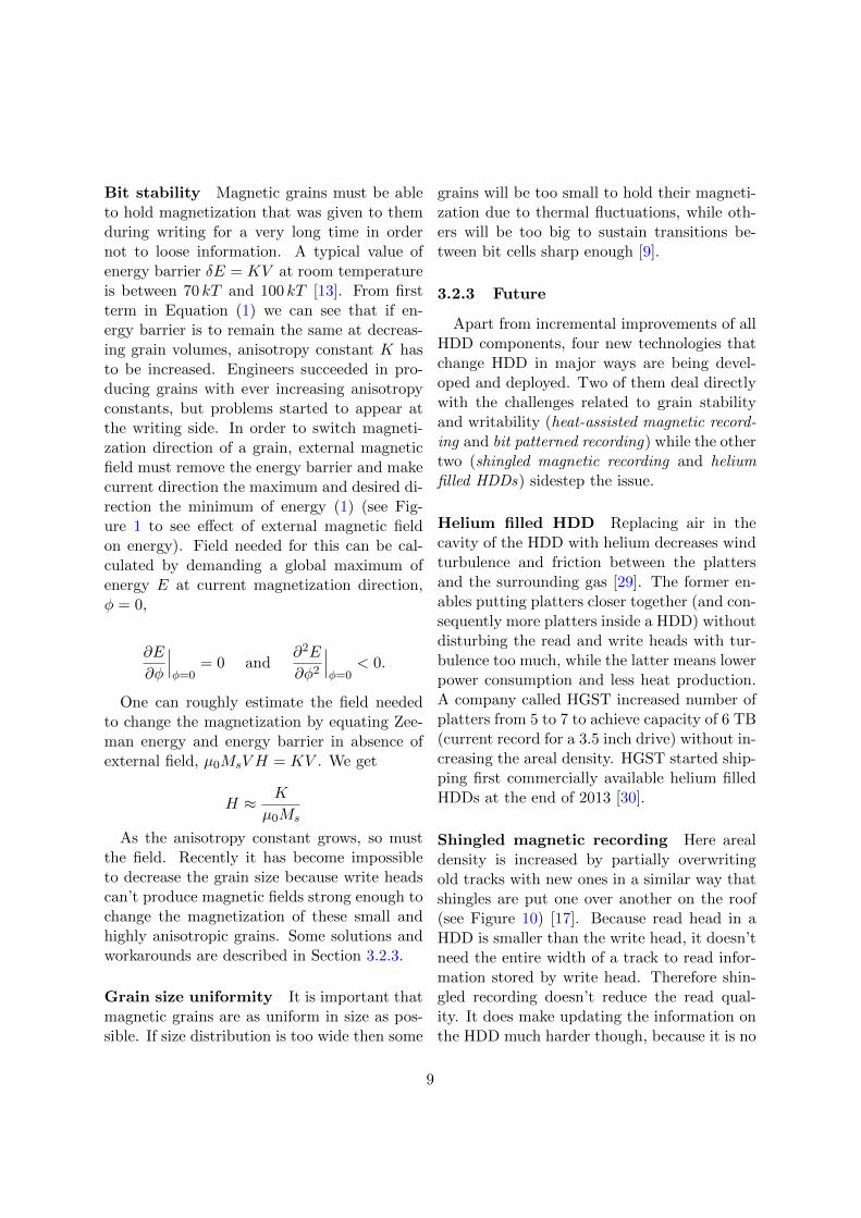
Shingled magnetic recording Here arealdensity is increased by partially overwritingold tracks with new ones in a similar way thatshingles are put one over another on the roof(see Figure 10) [17]. Because read head in aHDD is smaller than the write head, it doesn’tneed the entire width of a track to read infor-mation stored by write head. Therefore shin-gled recording doesn’t reduce the read qual-ity. It does make updating the information onthe HDD much harder though, because it is no
9
Figure 10: Tracks written by write head aregray, while parts of tracks needed by read headare green. Source of figure: [16].
longer possible to change just one single track.Write head is so wide that it always overwritesseveral trimmed tracks. When a trimmed trackis overwritten with new information, all shin-gled tracks above it have to be rewritten alsoin order not to loose their existing information.To alleviate this problem tracks are combinedin bands. Tracks from different bands don’toverlap which limits the number of tracks thatmight need to be rewritten. A big weakness ofSMR is longer write times, while its strengthis that it offers big increase in areal density(25 % with first generation products) with-out the need for drastic changes in read andwrite heads or platter design. Looks like thatfirst commercially available disks using SMRstarted shipping in the beginning of 2014 [15].
Heat-assisted magnetic recording(HAMR) Just before writing, grainsget heated with a laser beam which bothdecreases their magnetic anisotropy and alsoeffectively lowers energy barrier in units
of kT [31]. Seagate reached areal densityof 1 Tb/in2 using HAMR in the beginningof 2012 [5], which is a 30% increase overwhat is possible with conventional recording.Currently there are no commercially availableHDDs using HAMR.
Bit-patterned recording (BPR) In con-ventional recording media, bit cells touch eachother and each of them is made of many smallgrains. Grains have to be small in order toreduce the transition noise and consequentlyincrease signal to noise ratio. [32]
In bit patterned recording bit cells are litho-graphically patterned in ordered arrays withnon-magnetic material between them. Becausebit cells are separated there is no need to fillthem with small grains that would make tran-sition from one cell to the other as sharp aspossible. Instead each bit cell is a single pieceof magnet. These pieces are larger than grainsin conventional HDDs and therefore thermallymore stable, but they are still much smallerthan bit cells in conventional HDDs which arebuild of many grains. In 2013 company HGSTmade prototypes with magnetic islands 10 nmin width [33].
The problem with BPR is that it is diffi-cult to make ordered arrays of magnetic cellsof such a small size. Cells must be positionedalong the tracks very precisely or else problemswith reading and writing appear. Currentlythere are no commercially available HDDs us-ing BPR.
4 Conclusion
Superparamagnetic materials have uniqueproperties because of the sizes of their mag-netic building blocks. In some applicationsthese properties are desired (e.g. in ferroflu-ids) and in others one tries to avoid them (e.g.in HDDs). In any case, there is a lot of re-
10
search being done with the goal of optimizingsuperparamagnetic materials for the particularapplications at hand.
References
[1] B. Kokot, Kvantni kompas pticev, Seminar,http://mafija.fmf.uni-lj.si/seminar/files/
2013_2014/BostjanKokotSem_Ib_koncna1.pdf,2014.
[2] S. Mørup and M. F. Hansen, in Handbook of Mag-netism and Advanced Magnetic Materials, edited byH. Kronmuller and S Parkin (John Wiley & Sons,2007), Vol. 4, Chap. Superparamagnetic Particles.
[3] R. W. Chantrell, J. Popplewell and S. W. Charles,IEEE Trans. Magn., Mag-14, 75 (1978).
[4] https://en.wikipedia.org/wiki/Magnetic_
anisotropy, 22.3.2014.
[5] https://slo-tech.com/novice/t511661#crta,22.3.2014.
[6] C. G. Granqvist and R. A. Buhrman, “Ultrafinemetal particles”, J. Appl. Phys. 47, 2200 (1976).
[7] R. A. Buhrman and C. G. Granqvist, J. Appl. Phys.47, 2220 (1976).
[8] L. B. Kiss et al., Nanotechnology 10, 25 (1999).
[9] R. Wood, J. Magn. Magn. Mater. 321, 555 (2009).
[10] https://en.wikipedia.org/wiki/Hard_disk_
drive, 22.3.2014.
[11] E. Grochowski and R. E. Fontana, Jr., An Analy-sis of Flash and HDD Technology Trends, availableat http://www.flashmemorysummit.com/English/
Collaterals/Proceedings/2011/20110809_F2C_
GrochowskiFontana.pdf, 22.3.2014.
[12] R. Fontana, G. Decad and S. Hetzler. Tech-nology Roadmap Comparisons for TAPE,HDD, and NAND Flash: Implicationsfor Data Storage Applications, availableat http://www.digitalpreservation.gov/
meetings/documents/storage12/5-Fontana-
StorageMediaDenstiyfoRNANDTAPE.pdf, 22.3.2014.
[13] H. J. Richter, J. Magn. Magn. Mater. 321, 467(2009).
[14] https://en.wikipedia.org/wiki/Hard_disk_
drive_platter, 9.3.2014.
[15] http://www.techweekeurope.co.uk/news/acie-
enclosures-seagates-5tb-hdd-139720,13.3.2014.
[16] http://jon.severinsson.net/lwn/smr_track_
layout.png, 21.4.2014.
[17] http://www.hgst.com/science-of-storage/
emerging-technologies/shingled-magnetic-
recording, 13.3.2014.
[18] https://en.wikipedia.org/wiki/Stoner%E2%
80%93Wohlfarth_model, 22.3.2014.
[19] http://lmis1.epfl.ch/webdav/site/lmis1/
shared/Files/Lectures/Nanotechnology%
20for%20engineers/Archives/2004_05/
Superparamagnetism.pdf, 22.3.2014.
[20] https://en.wikipedia.org/wiki/Ferrofluid,22. 3. 2014.
[21] C. Scherer and A. M. Figueiredo Neto, Brazil. J.Phys. 35, 718 (2005).
[22] http://www.telemark.com/magnetic_fluid_
feedthroughs/the_principle_of.php?cat=
6&id=The%20Principle%20of%20Magnetic%
20Feedthroughs, 22.3.2014.
[23] http://en.rigaku-mechatronics.com/
technology/index.html#sealbunrui, 22.3.2014.
[24] https://en.wikipedia.org/wiki/
Magnetorheological_fluid, 22.3.2014.
[25] http://computinnovative.blogspot.com/2013/
03/parts-of-computer-system.html, 22.3.2014.
[26] https://www.youtube.com/watch?v=Wiy_
eHdj8kg, 22.3.2014.
[27] S. M. Thompson, J. Phys. D: Appl. Phys. 41093001, 2008.
[28] http://www.answers.com/topic/
perpendicular-recording, 22.3.2014.
[29] J. Rydning and D. Reinsel, Helium Taking HDDsto New Heights, White Paper, 2013.
[30] http://www.engadget.com/2013/11/04/first-
helium-filled-6tb-hard-drive/, 23.4.2014.
[31] M. H. Kryder et al, IEEE Proc. 96, 1810 (2008).
[32] http://phys.org/news/2011-09-patterned-
media-technique-terabit-densities.html,22.3.2014.
[33] http://www.hgst.com/press-room/press-
releases/hgst-reaches-10-nanometer-
patterned-bit-milestone-nanotechnology,21.4.2014.
11