Supercapacitor Development Balancing Kit
6
1 © KEMET Electronics Corporation • P.O. Box 5928 • Greenville, SC 29606 (864) 963-6300 • www.kemet.com S6010_S0KMOD0001 • 7/28/2014 One world. One KEMET Benefits • High frequency capacitance retention • High energy delivery capability • High reliability • Bus bars for module flexibility • Positive tab connection termination • Operating temperature range of -40°C to +105°C • Two-stage balancing • Overvoltage protection • RoHS compliant Overview The KEMET Supercapacitor Development Kit includes a two-stage active balancing circuit to complement the S301 Screw Terminal Supercapacitor Series. Each kit contains enough balancing cards, bus bars, screws, washers and wire to assemble six S301 60 mm diameter cells (sold separately). Applications Typical applications include medical, aerospace, defense, transportation, telecommunications, product validation, prototyping, low volume production and custom configurations. Supercapacitor Development Balancing Kit Characteristics Physical Required Cell Diameter 60 mm (nominal) Cell Orientation 0°, 30°, 60°, 90° Cells Available 1,200 F 3,000 F Management Individual Balancing 2.0 V for each cell Cell Orientation 5.4 V for cell pair Operations Configurations Must be used in even numbers Housing or other voltage isolation is the responsibility of the customer Current Bus bars designed for sub 1,000 A operation
Transcript of Supercapacitor Development Balancing Kit
1© KEMET Electronics Corporation • P.O. Box 5928 • Greenville, SC 29606 (864) 963-6300 • www.kemet.com S6010_S0KMOD0001 • 7/28/2014One world. One KEMET
Benefits
• High frequency capacitance retention• High energy delivery capability• High reliability• Busbarsformoduleflexibility• Positive tab connection termination• Operating temperature range of -40°C to +105°C• Two-stage balancing• Overvoltage protection• RoHS compliant
Overview
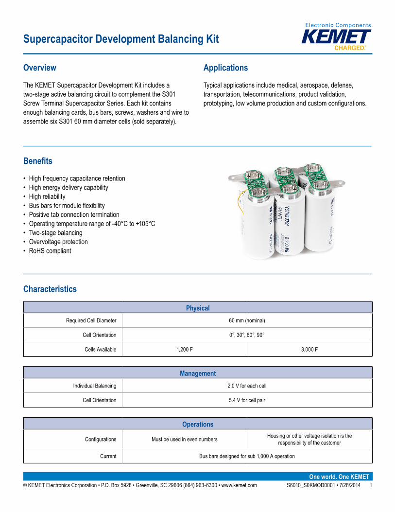
The KEMET Supercapacitor Development Kit includes a two-stage active balancing circuit to complement the S301 Screw Terminal Supercapacitor Series. Each kit contains enough balancing cards, bus bars, screws, washers and wire to assemble six S301 60 mm diameter cells (sold separately).
Applications
Typical applications include medical, aerospace, defense, transportation, telecommunications, product validation, prototyping,lowvolumeproductionandcustomconfigurations.
Supercapacitor Development Balancing Kit
Characteristics
PhysicalRequired Cell Diameter 60 mm (nominal)
Cell Orientation 0°, 30°, 60°, 90°
Cells Available 1,200 F 3,000 F
ManagementIndividual Balancing 2.0 V for each cell
Cell Orientation 5.4 V for cell pair
Operations
Configurations Must be used in even numbers Housing or other voltage isolation is the responsibility of the customer
Current Bus bars designed for sub 1,000 A operation
2© KEMET Electronics Corporation • P.O. Box 5928 • Greenville, SC 29606 (864) 963-6300 • www.kemet.com S6010_S0KMOD0001 • 7/28/2014
Supercapacitor Development Balancing Kit
Ordering Information
KEMET Part Number: S0KMOD0001
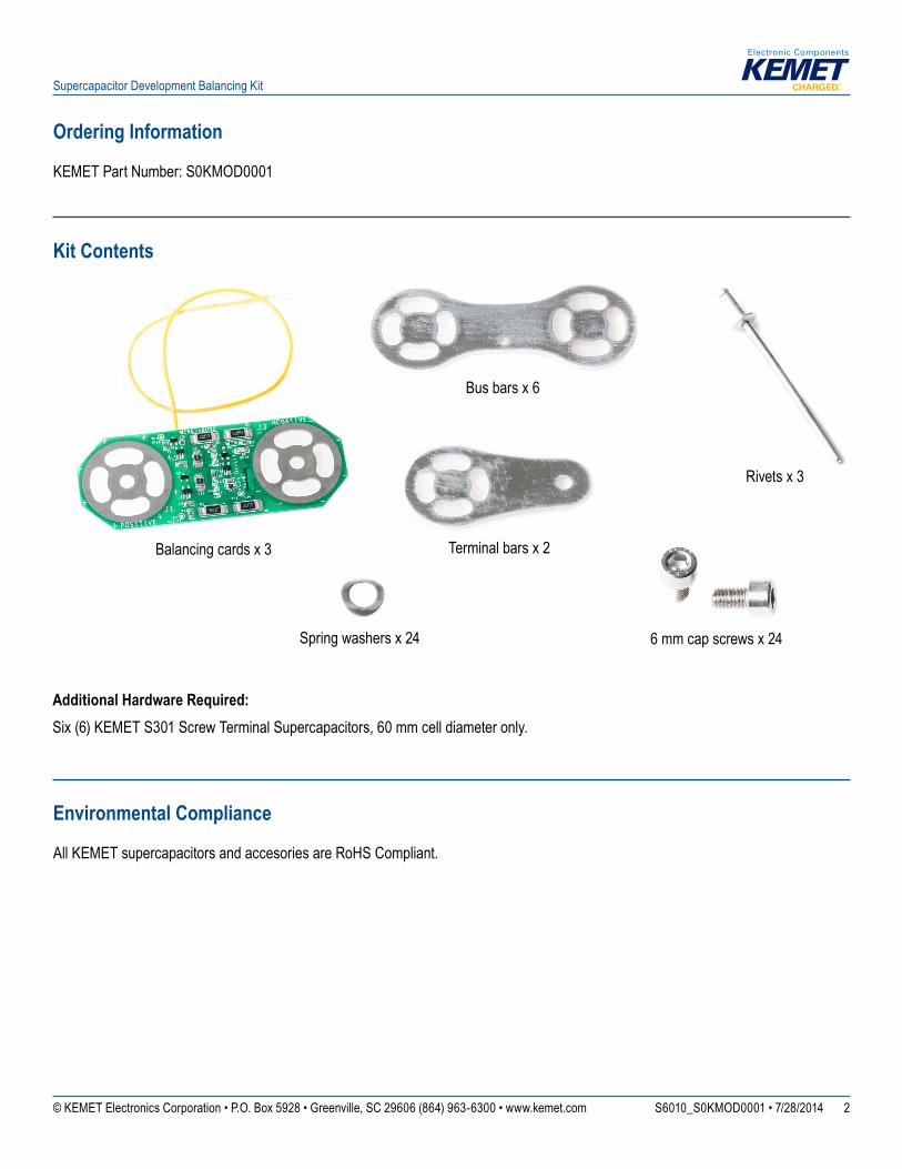
Kit Contents
Balancing cards x 3
Bus bars x 6
Terminal bars x 2
Rivets x 3
6 mm cap screws x 24Spring washers x 24
Environmental Compliance
All KEMET supercapacitors and accesories are RoHS Compliant.
Additional Hardware Required:Six (6) KEMET S301 Screw Terminal Supercapacitors, 60 mm cell diameter only.
3© KEMET Electronics Corporation • P.O. Box 5928 • Greenville, SC 29606 (864) 963-6300 • www.kemet.com S6010_S0KMOD0001 • 7/28/2014
Supercapacitor Development Balancing Kit
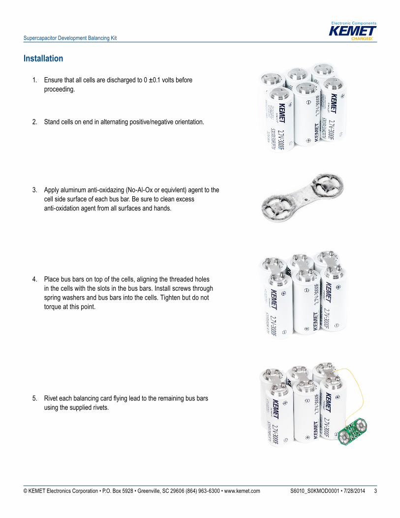
Installation
1. Ensure that all cells are discharged to 0 ±0.1 volts before proceeding.
2. Stand cells on end in alternating positive/negative orientation.
3. Apply aluminum anti-oxidazing (No-Al-Ox or equivlent) agent to the cell side surface of each bus bar. Be sure to clean excess anti-oxidation agent from all surfaces and hands.
4. Place bus bars on top of the cells, aligning the threaded holes in the cells with the slots in the bus bars. Install screws through spring washers and bus bars into the cells. Tighten but do not torque at this point.
5. Riveteachbalancingcardflyingleadtotheremainingbusbarsusing the supplied rivets.
4© KEMET Electronics Corporation • P.O. Box 5928 • Greenville, SC 29606 (864) 963-6300 • www.kemet.com S6010_S0KMOD0001 • 7/28/2014
Supercapacitor Development Balancing Kit
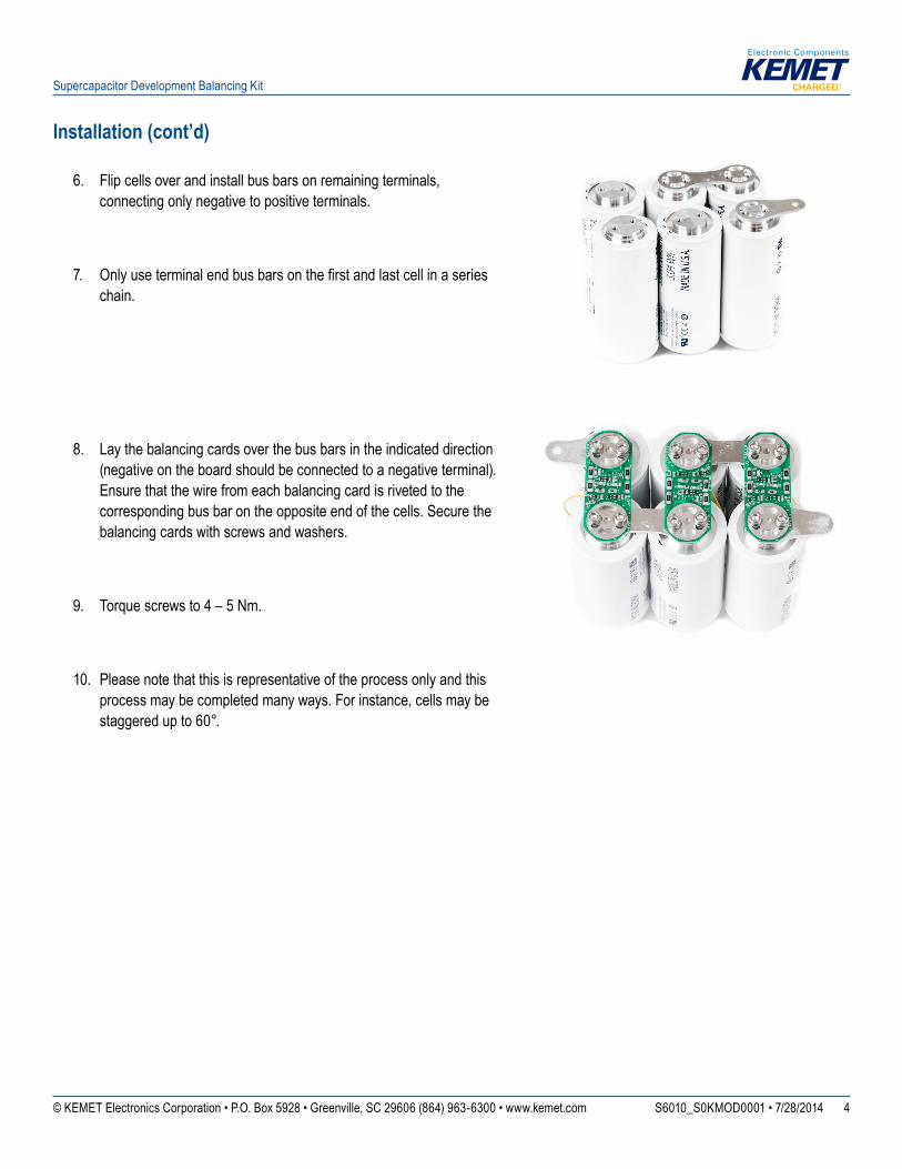
Installation (cont’d)
6. Flip cells over and install bus bars on remaining terminals, connecting only negative to positive terminals.
7. Onlyuseterminalendbusbarsonthefirstandlastcellinaserieschain.
8. Lay the balancing cards over the bus bars in the indicated direction (negative on the board should be connected to a negative terminal). Ensure that the wire from each balancing card is riveted to the corresponding bus bar on the opposite end of the cells. Secure the balancing cards with screws and washers.
9. Torque screws to 4 – 5 Nm.
10. Please note that this is representative of the process only and this process may be completed many ways. For instance, cells may be staggered up to 60°.
5© KEMET Electronics Corporation • P.O. Box 5928 • Greenville, SC 29606 (864) 963-6300 • www.kemet.com S6010_S0KMOD0001 • 7/28/2014
Supercapacitor Development Balancing Kit
KEMET Corporation World Headquarters
2835 KEMET WaySimpsonville, SC 29681
Mailing Address:P.O. Box 5928 Greenville, SC 29606
www.kemet.com Tel: 864-963-6300 Fax: 864-963-6521
Corporate Offi cesFort Lauderdale, FLTel: 954-766-2800
North America
SoutheastLake Mary, FLTel: 407-855-8886
NortheastWilmington, MATel: 978-658-1663
CentralNovi, MITel: 248-306-9353
WestMilpitas, CATel: 408-433-9950
Mexico Guadalajara, Jalisco Tel: 52-33-3123-2141
Europe
Southern EuropeParis, FranceTel: 33-1-4646-1006
Sasso Marconi, ItalyTel: 39-051-939111
Central EuropeLandsberg, Germany Tel: 49-8191-3350800
Kamen, GermanyTel: 49-2307-438110
Northern EuropeBishop’s Stortford, United Kingdom Tel: 44-1279-460122
Espoo, FinlandTel: 358-9-5406-5000
Asia
Northeast AsiaHong KongTel: 852-2305-1168
Shenzhen, ChinaTel: 86-755-2518-1306
Beijing, ChinaTel: 86-10-5829-1711
Shanghai, ChinaTel: 86-21-6447-0707
Taipei, TaiwanTel: 886-2-27528585
Southeast AsiaSingaporeTel: 65-6586-1900
Penang, MalaysiaTel: 60-4-6430200
Bangalore, IndiaTel: 91-806-53-76817
Note: KEMET reserves the right to modify minor details of internal and external construction at any time in the interest of product improvement. KEMET does not assume any responsibility for infringement that might result from the use of KEMET Capacitors in potential circuit designs. KEMET is a registered trademark of KEMET Electronics Corporation.
6© KEMET Electronics Corporation • P.O. Box 5928 • Greenville, SC 29606 (864) 963-6300 • www.kemet.com S6010_S0KMOD0001 • 7/28/2014
Supercapacitor Development Balancing Kit
DisclaimerAll product specifi cations, statements, information and data (collectively, the “Information”) in this datasheet are subject to change. The customer is responsible for checking and verifying the extent to which the Information contained in this publication is applicable to an order at the time the order is placed.
All Information given herein is believed to be accurate and reliable, but it is presented without guarantee, warranty, or responsibility of any kind, expressed or implied.
Statements of suitability for certain applications are based on KEMET Electronics Corporation’s (“KEMET”) knowledge of typical operating conditions for such applications, but are not intended to constitute – and KEMET specifi cally disclaims – any warranty concerning suitability for a specifi c customer application or use. The Information is intended for use only by customers who have the requisite experience and capability to determine the correct products for their application. Any technical advice inferred from this Information or otherwise provided by KEMET with reference to the use of KEMET’s products is given gratis, and KEMET assumes no obligation or liability for the advice given or results obtained.
Although KEMET designs and manufactures its products to the most stringent quality and safety standards, given the current state of the art, isolated component failures may still occur. Accordingly, customer applications which require a high degree of reliability or safety should employ suitable designs or other safeguards (such as installation of protective circuitry or redundancies) in order to ensure that the failure of an electrical component does not result in a risk of personal injury or property damage.
Although all product–related warnings, cautions and notes must be observed, the customer should not assume that all safety measures are indicted or that other measures may not be required.