Capacity Design of Supercapacitor Battery Hybrid...
6
Capacity Design of Supercapacitor Battery Hybrid Energy Storage System with Repetitive Charging via Wireless Power Transfer Toshiyuki Hiramatsu Department of Electric Engineering The University of Tokyo Kashiwanoha, Kashiwa, Chiba, Japan Email: [email protected] Xiaoliang Huang Graduate School of Frontier Science The University of Tokyo Kashiwanoha, Kashiwa, Chiba, Japan Email: [email protected] Yoichi Hori Graduate School of Frontier Science The University of Tokyo Kashiwanoha, Kashiwa, Chiba, Japan Email: [email protected] Abstract—The widely used energy storage system for electric vehicle and electric operating machine based on battery has critical disadvantages. A solution for this problem is the use of battery/Supercapacitor (SC) hybrid energy storage system (HESS) due to advantages of SC in high power density, high cycle capability, and long life time. However, energy density of electric energy storage is much lower than the one of combustion engine. A solution for these problem is the repetitive charge for HESS via Wireless Power Transfer (WPT). In order to improve the transmission efficiency, the method of using a DC-DC converter to control secondary input impedance has been proposed in previous research. In this paper, a framework of HESS with WPT charging system is proposed for vehicle and electric operating machine application. Furthermore, capacity of HESS with WPT repetitive charging is designed, based on the requirements of the application. Index Terms—Supercapacitor, Battery, Hybrid Energy Storage System, Repetitive Charging, Wireless Power Transfer, Capacity Design. I. I NTRODUCTION Energy storage system is a key point in electric vehicles (EV) and electric operational machines. One of the most commonly used energy storage devices is battery. However, battery has three critical disadvantages. The first one is that charging/discharging speed is slow due to battery stores energy with chemical reactions.The second one is that battery energy density is lower than that of combustion engine. The third one is that the lifetime is short because battery is damaged by charge and discharge. A common solution of these problems is to equip huge batteries on board but such battery is expensive and heavy [1]. In order to solve these problems, battery/supercapacitor (SC) Hybrid Energy Storage System (HESS) has been pro- posed [2], [3]. SC as energy storage device has been widely used because SC has high power density, high cycling capa- bility, and long life time [4]∼[6]. Due to these advantages of SC, for EV application, HESS can achieve high acceleration performance, high efficiency of regenerative brake, extension of battery life, and low cost. However, energy capacity of HESS is limited for long- distance cruising. In order to improve the cruising range of Fig. 1. The scheme of system applied WPT to HESS. EV and electric operational machine, HESS must be charged repetitively. The plug-in charge brings some problems and it can be an obstacle for automatic operation [7]. WPT via magnetic resonant coupling is suitable to repetitive charge [8]∼[10]. This method, introduced in 2007, allows high transmission efficiency over relatively larger gap, compared to induction method. For high transmission efficiency, controlling load impedance with DC-DC converter is proposed [11]. When the designing actual system, it is necessary to design the capacity of system as well. Previous researchers proposed a capacity design of HESS, however they did not consider repetitive charging [12], [13]. In this paper, a framework of HESS with WPT charging system is proposed for vehicle and electric operating machine application and the capacity of HESS with WPT repetitive charging is designed, based on the requirements of the application. II. HESS WITH WPT CHARGING SYSTEM Fig. 1 shows the WPT system applied to HESS. In this research, this topology is considered. In this topology, DC- link voltage is fixed as battery voltage because battery is connected directly to DC-link. Transmission power from WPT is absorbed by battery and SC or consumed by motor. The
Transcript of Capacity Design of Supercapacitor Battery Hybrid...
Capacity Design of Supercapacitor Battery HybridEnergy Storage System with Repetitive Charging
via Wireless Power TransferToshiyuki Hiramatsu
Department of Electric EngineeringThe University of Tokyo
Kashiwanoha, Kashiwa, Chiba, JapanEmail: [email protected]
Xiaoliang HuangGraduate School of Frontier Science
The University of TokyoKashiwanoha, Kashiwa, Chiba, JapanEmail: [email protected]
Yoichi HoriGraduate School of Frontier Science
The University of TokyoKashiwanoha, Kashiwa, Chiba, Japan
Email: [email protected]
Abstract—The widely used energy storage system for electricvehicle and electric operating machine based on battery hascritical disadvantages. A solution for this problem is the useof battery/Supercapacitor (SC) hybrid energy storage system(HESS) due to advantages of SC in high power density, high cyclecapability, and long life time. However, energy density of electricenergy storage is much lower than the one of combustion engine.A solution for these problem is the repetitive charge for HESSvia Wireless Power Transfer (WPT). In order to improve thetransmission efficiency, the method of using a DC-DC converterto control secondary input impedance has been proposed inprevious research. In this paper, a framework of HESS with WPTcharging system is proposed for vehicle and electric operatingmachine application. Furthermore, capacity of HESS with WPTrepetitive charging is designed, based on the requirements of theapplication.
Index Terms—Supercapacitor, Battery, Hybrid Energy StorageSystem, Repetitive Charging, Wireless Power Transfer, CapacityDesign.
I. I NTRODUCTION
Energy storage system is a key point in electric vehicles(EV) and electric operational machines. One of the mostcommonly used energy storage devices is battery. However,battery has three critical disadvantages. The first one is thatcharging/discharging speed is slow due to battery stores energywith chemical reactions.The second one is that battery energydensity is lower than that of combustion engine. The thirdone is that the lifetime is short because battery is damaged bycharge and discharge. A common solution of these problems isto equip huge batteries on board but such battery is expensiveand heavy [1].
In order to solve these problems, battery/supercapacitor(SC) Hybrid Energy Storage System (HESS) has been pro-posed [2], [3]. SC as energy storage device has been widelyused because SC has high power density, high cycling capa-bility, and long life time [4]∼[6]. Due to these advantages ofSC, for EV application, HESS can achieve high accelerationperformance, high efficiency of regenerative brake, extensionof battery life, and low cost.
However, energy capacity of HESS is limited for long-distance cruising. In order to improve the cruising range of
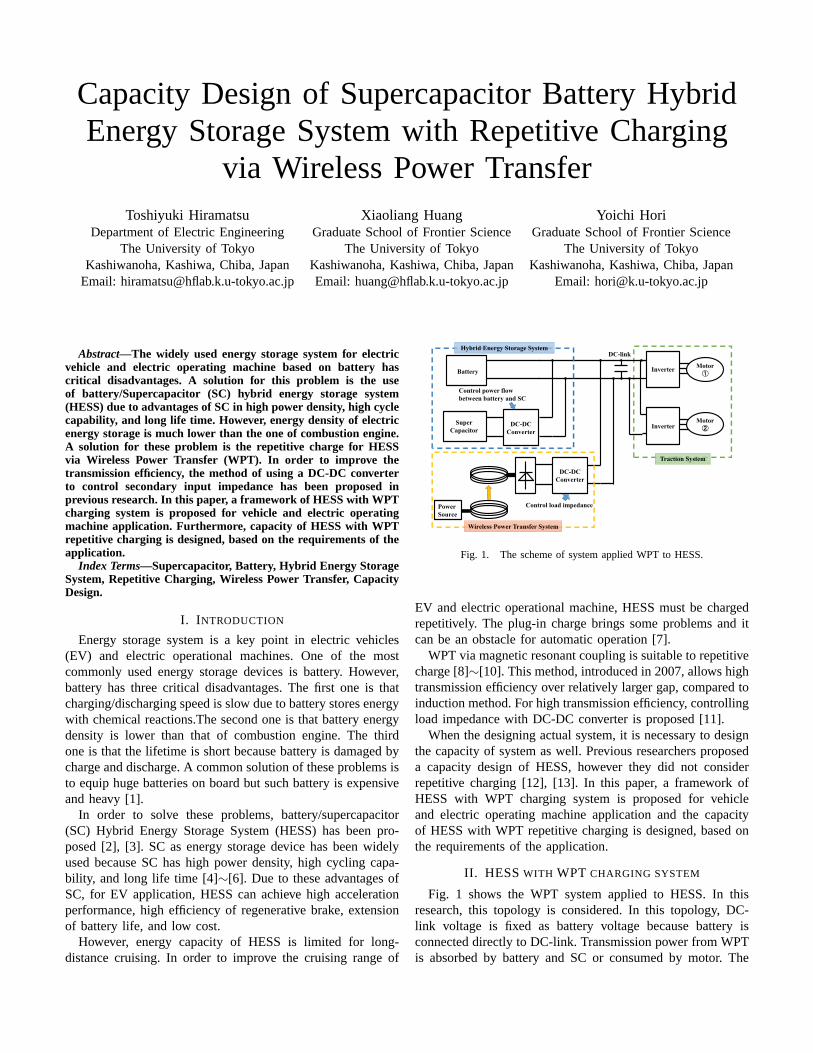
Fig. 1. The scheme of system applied WPT to HESS.
EV and electric operational machine, HESS must be chargedrepetitively. The plug-in charge brings some problems and itcan be an obstacle for automatic operation [7].
WPT via magnetic resonant coupling is suitable to repetitivecharge [8]∼[10]. This method, introduced in 2007, allows hightransmission efficiency over relatively larger gap, compared toinduction method. For high transmission efficiency, controllingload impedance with DC-DC converter is proposed [11].
When the designing actual system, it is necessary to designthe capacity of system as well. Previous researchers proposeda capacity design of HESS, however they did not considerrepetitive charging [12], [13]. In this paper, a framework ofHESS with WPT charging system is proposed for vehicleand electric operating machine application and the capacityof HESS with WPT repetitive charging is designed, based onthe requirements of the application.
II. HESSWITH WPT CHARGING SYSTEM
Fig. 1 shows the WPT system applied to HESS. In thisresearch, this topology is considered. In this topology, DC-link voltage is fixed as battery voltage because battery isconnected directly to DC-link. Transmission power from WPTis absorbed by battery and SC or consumed by motor. The
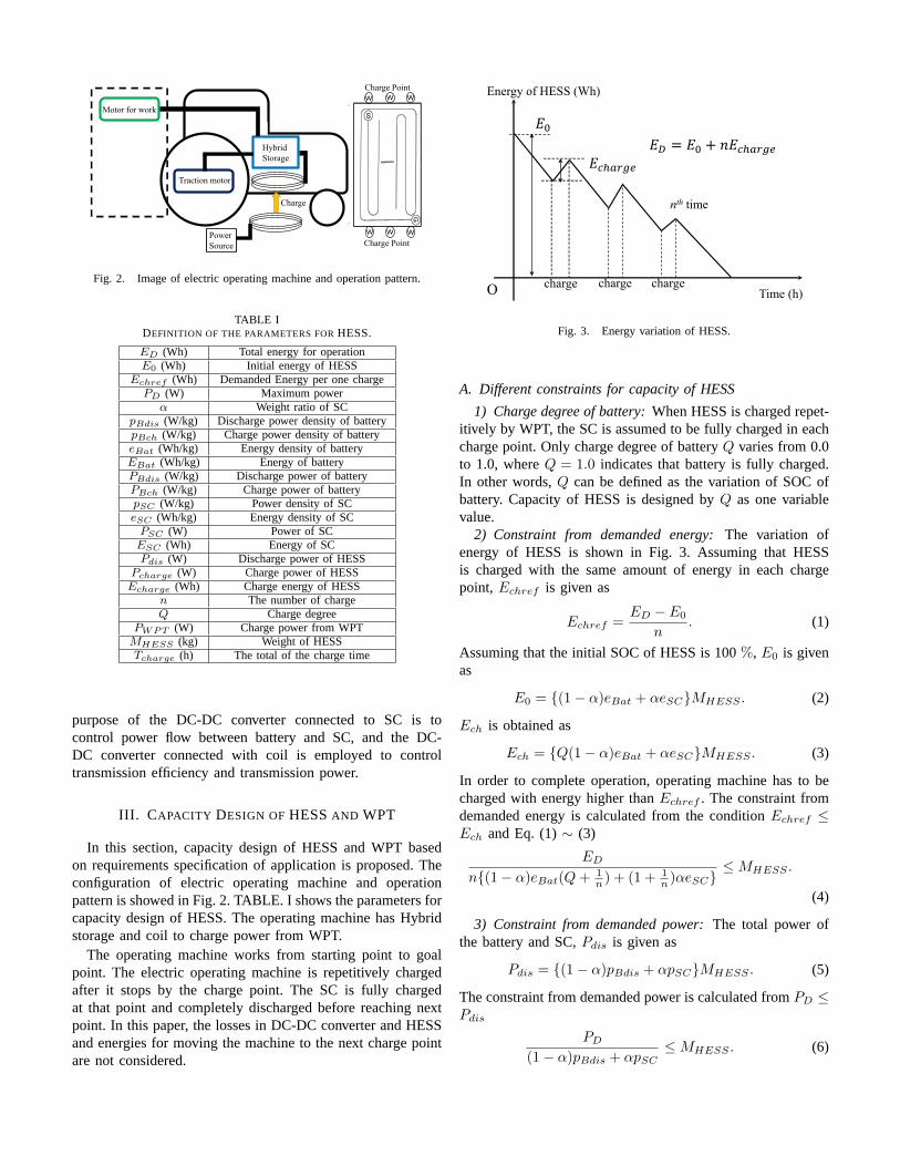
Fig. 2. Image of electric operating machine and operation pattern.
TABLE IDEFINITION OF THE PARAMETERS FORHESS.
ED (Wh) Total energy for operationE0 (Wh) Initial energy of HESS
Echref (Wh) Demanded Energy per one chargePD (W) Maximum power
α Weight ratio of SCpBdis (W/kg) Discharge power density of batterypBch (W/kg) Charge power density of batteryeBat (Wh/kg) Energy density of batteryEBat (Wh/kg) Energy of batteryPBdis (W/kg) Discharge power of batteryPBch (W/kg) Charge power of batterypSC (W/kg) Power density of SCeSC (Wh/kg) Energy density of SCPSC (W) Power of SCESC (Wh) Energy of SCPdis (W) Discharge power of HESS
Pcharge (W) Charge power of HESSEcharge (Wh) Charge energy of HESS
n The number of chargeQ Charge degree
PWPT (W) Charge power from WPTMHESS (kg) Weight of HESSTcharge (h) The total of the charge time
purpose of the DC-DC converter connected to SC is tocontrol power flow between battery and SC, and the DC-DC converter connected with coil is employed to controltransmission efficiency and transmission power.
III. C APACITY DESIGN OFHESSAND WPT
In this section, capacity design of HESS and WPT basedon requirements specification of application is proposed. Theconfiguration of electric operating machine and operationpattern is showed in Fig. 2. TABLE. I shows the parameters forcapacity design of HESS. The operating machine has Hybridstorage and coil to charge power from WPT.
The operating machine works from starting point to goalpoint. The electric operating machine is repetitively chargedafter it stops by the charge point. The SC is fully chargedat that point and completely discharged before reaching nextpoint. In this paper, the losses in DC-DC converter and HESSand energies for moving the machine to the next charge pointare not considered.
Fig. 3. Energy variation of HESS.
A. Different constraints for capacity of HESS
1) Charge degree of battery:When HESS is charged repet-itively by WPT, the SC is assumed to be fully charged in eachcharge point. Only charge degree of batteryQ varies from 0.0to 1.0, whereQ = 1.0 indicates that battery is fully charged.In other words,Q can be defined as the variation of SOC ofbattery. Capacity of HESS is designed byQ as one variablevalue.
2) Constraint from demanded energy:The variation ofenergy of HESS is shown in Fig. 3. Assuming that HESSis charged with the same amount of energy in each chargepoint, Echref is given as
Echref =ED − E0
n. (1)
Assuming that the initial SOC of HESS is 100%, E0 is givenas
E0 = {(1− α)eBat + αeSC}MHESS . (2)
Ech is obtained as
Ech = {Q(1− α)eBat + αeSC}MHESS . (3)
In order to complete operation, operating machine has to becharged with energy higher thanEchref . The constraint fromdemanded energy is calculated from the conditionEchref ≤Ech and Eq. (1)∼ (3)
ED
n{(1− α)eBat(Q+ 1n ) + (1 + 1
n )αeSC}≤ MHESS .
(4)
3) Constraint from demanded power:The total power ofthe battery and SC,Pdis is given as
Pdis = {(1− α)pBdis + αpSC}MHESS . (5)
The constraint from demanded power is calculated fromPD ≤Pdis
PD
(1− α)pBdis + αpSC≤ MHESS . (6)
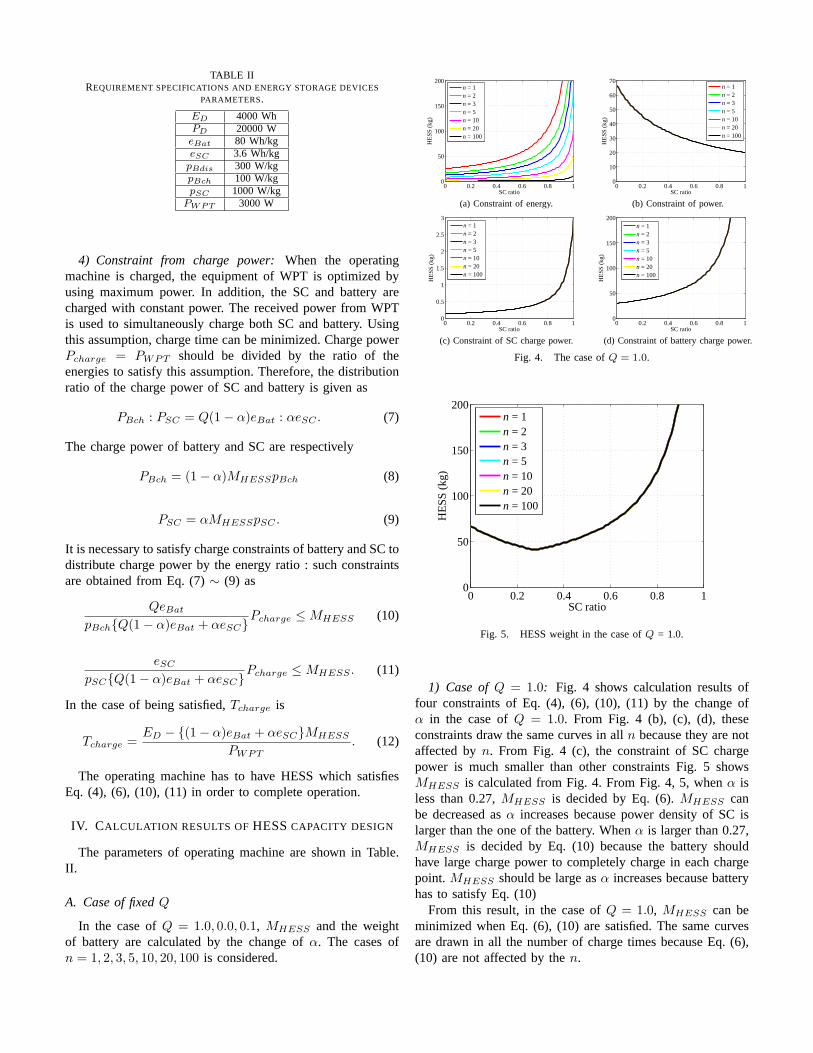
TABLE IIREQUIREMENT SPECIFICATIONS AND ENERGY STORAGE DEVICES
PARAMETERS.
ED 4000 WhPD 20000 WeBat 80 Wh/kgeSC 3.6 Wh/kgpBdis 300 W/kgpBch 100 W/kgpSC 1000 W/kg
PWPT 3000 W
4) Constraint from charge power:When the operatingmachine is charged, the equipment of WPT is optimized byusing maximum power. In addition, the SC and battery arecharged with constant power. The received power from WPTis used to simultaneously charge both SC and battery. Usingthis assumption, charge time can be minimized. Charge powerPcharge = PWPT should be divided by the ratio of theenergies to satisfy this assumption. Therefore, the distributionratio of the charge power of SC and battery is given as
PBch : PSC = Q(1− α)eBat : αeSC . (7)
The charge power of battery and SC are respectively
PBch = (1− α)MHESSpBch (8)
PSC = αMHESSpSC . (9)
It is necessary to satisfy charge constraints of battery and SC todistribute charge power by the energy ratio : such constraintsare obtained from Eq. (7)∼ (9) as
QeBat
pBch{Q(1− α)eBat + αeSC}Pcharge ≤ MHESS (10)
eSC
pSC{Q(1− α)eBat + αeSC}Pcharge ≤ MHESS . (11)
In the case of being satisfied,Tcharge is
Tcharge =ED − {(1− α)eBat + αeSC}MHESS
PWPT. (12)
The operating machine has to have HESS which satisfiesEq. (4), (6), (10), (11) in order to complete operation.
IV. CALCULATION RESULTS OFHESSCAPACITY DESIGN
The parameters of operating machine are shown in Table.II.
A. Case of fixedQ
In the case ofQ = 1.0, 0.0, 0.1, MHESS and the weightof battery are calculated by the change ofα. The cases ofn = 1, 2, 3, 5, 10, 20, 100 is considered.
0 0.2 0.4 0.6 0.8 10
50
100
150
200
SC ratio
HE
SS (
kg)
n = 1n = 2n = 3n = 5n = 10n = 20n = 100
(a) Constraint of energy.
0 0.2 0.4 0.6 0.8 10
10
20
30
40
50
60
70
SC ratio
HE
SS (
kg)
n = 1n = 2n = 3n = 5n = 10n = 20n = 100
(b) Constraint of power.
0 0.2 0.4 0.6 0.8 10
0.5
1
1.5
2
2.5
3
SC ratio
HE
SS (
kg)
n = 1n = 2n = 3n = 5n = 10n = 20n = 100
(c) Constraint of SC charge power.
0 0.2 0.4 0.6 0.8 10
50
100
150
200
SC ratio
HE
SS (
kg)
n = 1n = 2n = 3n = 5n = 10n = 20n = 100
(d) Constraint of battery charge power.
Fig. 4. The case ofQ = 1.0.
0 0.2 0.4 0.6 0.8 10
50
100
150
200
SC ratio
HE
SS (
kg)
n = 1n = 2n = 3n = 5n = 10n = 20n = 100
Fig. 5. HESS weight in the case ofQ = 1.0.
1) Case ofQ = 1.0: Fig. 4 shows calculation results offour constraints of Eq. (4), (6), (10), (11) by the change ofα in the case ofQ = 1.0. From Fig. 4 (b), (c), (d), theseconstraints draw the same curves in alln because they are notaffected byn. From Fig. 4 (c), the constraint of SC chargepower is much smaller than other constraints Fig. 5 showsMHESS is calculated from Fig. 4. From Fig. 4, 5, whenα isless than 0.27,MHESS is decided by Eq. (6).MHESS canbe decreased asα increases because power density of SC islarger than the one of the battery. Whenα is larger than 0.27,MHESS is decided by Eq. (10) because the battery shouldhave large charge power to completely charge in each chargepoint.MHESS should be large asα increases because batteryhas to satisfy Eq. (10)
From this result, in the case ofQ = 1.0, MHESS can beminimized when Eq. (6), (10) are satisfied. The same curvesare drawn in all the number of charge times because Eq. (6),(10) are not affected by then.
0 0.2 0.4 0.6 0.8 10
50
100
150
200
SC ratio
HE
SS (
kg)
n = 1n = 2n = 3n = 5n = 10n = 20n = 100
(a) Constraint of demanded energy.
0 0.2 0.4 0.6 0.8 10
10
20
30
40
50
60
70
SC ratio
HE
SS (
kg)
n = 1n = 2n = 3n = 5n = 10n = 20n = 100
(b) Constraint of demanded power.
0 0.2 0.4 0.6 0.8 10
50
100
150
200
SC ratio
HE
SS (
kg)
n = 1n = 2n = 3n = 5n = 10n = 20n = 100
(c) Constraint of SC charge power.
0 0.2 0.4 0.6 0.8 1−1
−0.5
0
0.5
1
SC ratio
HE
SS
(kg
)
n = 1n = 2n = 3n = 5n = 10n = 20n = 100
(d) Constraint of battery charge power.
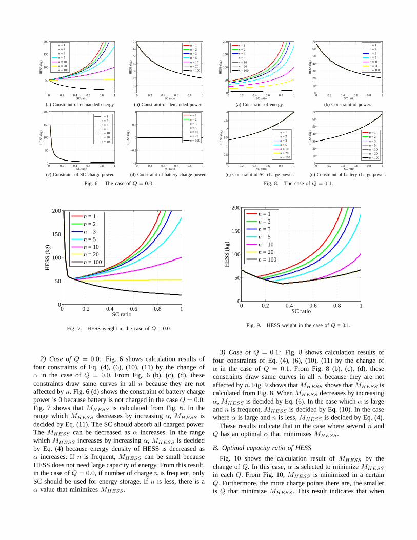
Fig. 6. The case ofQ = 0.0.
0 0.2 0.4 0.6 0.8 10
50
100
150
200
SC ratio
HE
SS (
kg)
n = 1n = 2n = 3n = 5n = 10n = 20n = 100
Fig. 7. HESS weight in the case ofQ = 0.0.
2) Case ofQ = 0.0: Fig. 6 shows calculation results offour constraints of Eq. (4), (6), (10), (11) by the change ofα in the case ofQ = 0.0. From Fig. 6 (b), (c), (d), theseconstraints draw same curves in alln because they are notaffected byn. Fig. 6 (d) shows the constraint of battery chargepower is 0 because battery is not charged in the caseQ = 0.0.Fig. 7 shows thatMHESS is calculated from Fig. 6. In therange whichMHESS decreases by increasingα, MHESS isdecided by Eq. (11). The SC should absorb all charged power.The MHESS can be decreased asα increases. In the rangewhich MHESS increases by increasingα, MHESS is decidedby Eq. (4) because energy density of HESS is decreased asα increases. Ifn is frequent,MHESS can be small becauseHESS does not need large capacity of energy. From this result,in the case ofQ = 0.0, if number of chargen is frequent, onlySC should be used for energy storage. Ifn is less, there is aα value that minimizesMHESS .
0 0.2 0.4 0.6 0.8 10
50
100
150
200
SC ratio
HE
SS (
kg)
n = 1n = 2n = 3n = 5n = 10n = 20n = 100
(a) Constraint of energy.
0 0.2 0.4 0.6 0.8 10
10
20
30
40
50
60
70
SC ratio
HE
SS (
kg)
n = 1n = 2n = 3n = 5n = 10n = 20n = 100
(b) Constraint of power.
0 0.2 0.4 0.6 0.8 10
0.5
1
1.5
2
2.5
3
SC ratio
HE
SS (
kg)
n = 1n = 2n = 3n = 5n = 10n = 20n = 100
(c) Constraint of SC charge power.
0 0.2 0.4 0.6 0.8 10
10
20
30
40
50
60
70
SC ratio
HE
SS (
kg)
n = 1n = 2n = 3n = 5n = 10n = 20n = 100
(d) Constraint of battery charge power.
Fig. 8. The case ofQ = 0.1.
0 0.2 0.4 0.6 0.8 10
50
100
150
200
SC ratio
HE
SS (
kg)
n = 1n = 2n = 3n = 5n = 10n = 20n = 100
Fig. 9. HESS weight in the case ofQ = 0.1.
3) Case ofQ = 0.1: Fig. 8 shows calculation results offour constraints of Eq. (4), (6), (10), (11) by the change ofα in the case ofQ = 0.1. From Fig. 8 (b), (c), (d), theseconstraints draw same curves in alln because they are notaffected byn. Fig. 9 shows thatMHESS shows thatMHESS iscalculated from Fig. 8. WhenMHESS decreases by increasingα, MHESS is decided by Eq. (6). In the case whichα is largeandn is frequent,MHESS is decided by Eq. (10). In the casewhereα is large andn is less,MHESS is decided by Eq. (4).
These results indicate that in the case where severaln andQ has an optimalα that minimizesMHESS .
B. Optimal capacity ratio of HESS
Fig. 10 shows the calculation result ofMHESS by thechange ofQ. In this case,α is selected to minimizeMHESS
in eachQ. From Fig. 10,MHESS is minimized in a certainQ. Furthermore, the more charge points there are, the smalleris Q that minimizeMHESS . This result indicates that when
0 0.2 0.4 0.6 0.8 125
30
35
40
45
50
55
Q
HE
SS (
kg)
n = 1n = 2n = 3n = 5n = 10n = 20
Fig. 10. HESS weight in the case of changing 3.0 kW.
n increases, the battery charge energy in each charge pointcan be small. Therefore, ifn is frequent, only SC should beequipped as an energy storage system.
The condition to minimizeMHESS is that Eq. (4), (6), (10)should be the same. In this case, Eq. (11) is not consideredbecause Eq. (11) affects only to decide minimumMHESS
whenQ is very small due to high power density. From Fig.10, if MHESS is charged many times,MHESS can be small.However, the number of charge times is related to the numberof charge points. If the number of charge points is not enough,operating machine should move to charge points. In brief, thenumber of charge times is limited.
C. Effect of Charge Power
Fig. 11, 12 shows the result of calculation ofMHESS inthe case ofPWPT = 1.5 kW, 4.5kW. The minimumMHESS
increases asPWPT becomes larger. SinceMHESS shouldbe large to satisfy Eq. (10). From this result, the minimumMHESS can be small ifPWPT is small. However, ifPWPT
is small,Tcharge should be extended. Therefore,PWPT shouldbe chosen in consideration ofTcharge. In addition, the optimalQ becomes smaller asPWPT becomes larger. This indicatesthat SC is suitable to charge huge power.
D. Capacity design guidance of HESS
As above the minimumMHESS is obtained when
ED
n{(1− α)eBat(Q+ 1n ) + (1 + 1
n )αeSC}= MHESS . (13)
PD
(1− α)pBdis + αpSC= MHESS . (14)
QeBat
pBch{Q(1− α)eBat + αeSC}PWPT = MHESS . (15)
are satisfied. IfPWPT is decided, variable parameters areMHESS , n,Q, α. Therefore, the minimumMHESS can be cal-culated by giving one variable parameter. From these results,
0 0.2 0.4 0.6 0.8 125
30
35
40
45
50
55
Q
HE
SS (
kg)
n = 1n = 2n = 3n = 5n = 10n = 20
Fig. 11. HESS weight in the case of changing 1.5 kW.
0 0.2 0.4 0.6 0.8 125
30
35
40
45
50
55
Q
HE
SS (
kg)
n = 1n = 2n = 3n = 5n = 10n = 20
Fig. 12. HESS weight in the case of changing 4.5 kW.
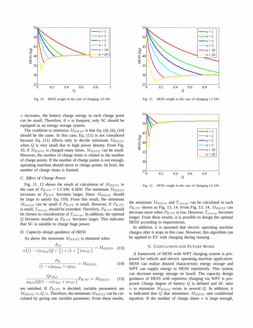
the minimumMHESS andTcharge can be calculated in eachPWPT shown as Fig. 13, 14. From Fig. 13, 14,MHESS candecrease more whenPWPT is low. However,Tcharge becomeslonger. From these results, it is possible to design the optimalHESS according to requirements.
In addition, it is assumed that electric operating machinecharges after it stops in this case. However, this algorithm canbe applied to EV with charging during running.
V. CONCLUSION AND FUTURE WORK
A framework of HESS with WPT charging system is pro-posed for vehicle and electric operating machine application.HESS can realize desired characteristic energy storage andWPT can supply energy to HESS repetitively. This systemcan decrease energy storage on board. The capacity designguidance of HESS with repetitive charging via WPT is pro-posed. Charge degree of batteryQ is defined and SC ratioα to minimize MHESS exists in severalQ. In addition, itis indicated thatQ that minimizesMHESS and conditionalequation. If the number of charge timesn is large enough,
1000 1500 2000 2500 3000 3500 400020
25
30
35
40
45
50
PWPT
(W)
Min
imum
HE
SS (
kg)
n = 1n = 2n = 3n = 5n = 10n = 20
Fig. 13. PWPT VS minimumMHESS .
1000 1500 2000 2500 3000 3500 40000
0.5
1
1.5
2
2.5
3
3.5
PWPT
(W)
Tch
arge
(h)
n = 1n = 2n = 3n = 5n = 10n = 20
Fig. 14. PWPT VS Tcharge.
energy storage should be only a SC, since it does not need tostore a lot of energy.
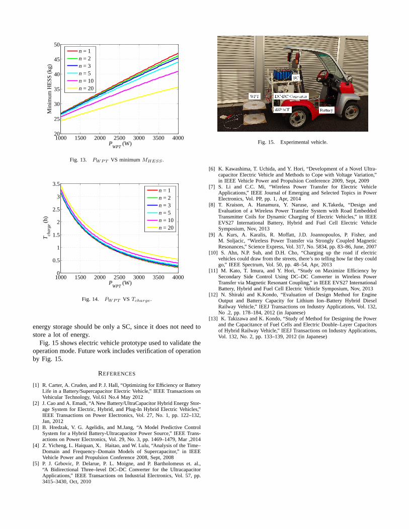
Fig. 15 shows electric vehicle prototype used to validate theoperation mode. Future work includes verification of operationby Fig. 15.
REFERENCES
[1] R. Carter, A. Cruden, and P. J. Hall, “Optimizing for Efficiency or BatteryLife in a Battery/Supercapacitor Electric Vehicle,” IEEE Transactions onVehicular Technology, Vol.61 No.4 May 2012
[2] J. Cao and A. Emadi, “A New Battery/UltraCapacitor Hybrid Energy Stor-age System for Electric, Hybrid, and Plug-In Hybrid Electric Vehicles,”IEEE Transactions on Power Electronics, Vol. 27, No. 1, pp. 122–132,Jan, 2012
[3] B. Hredzak, V. G. Agelidis, and M.Jang, “A Model Predictive ControlSystem for a Hybrid Battery-Ultracapacitor Power Source,” IEEE Trans-actions on Power Electronics, Vol. 29, No. 3, pp. 1469–1479, Mar ,2014
[4] Z. Yicheng, L. Haiquan, X。Haitao, and W. Lulu, “Analysis of the Time–Domain and Frequency–Domain Models of Supercapacitor,” in IEEEVehicle Power and Propulsion Conference 2008, Sept, 2008
[5] P. J. Grbovic, P. Delarue, P. L. Moigne, and P. Bartholomeus et. al.,“A Bidirectional Three–level DC–DC Converter for the UltracapacitorApplications,” IEEE Transactions on Industrial Electronics, Vol. 57, pp.3415–3430, Oct, 2010
Fig. 15. Experimental vehicle.
[6] K. Kawashima, T. Uchida, and Y. Hori, “Development of a Novel Ultra-capacitor Electric Vehicle and Methods to Cope with Voltage Variation,”in IEEE Vehicle Power and Propulsion Conference 2009, Sept, 2009
[7] S. Li and C.C. Mi, “Wireless Power Transfer for Electric VehicleApplications,” IEEE Journal of Emerging and Selected Topics in PowerElectronics, Vol. PP, pp. 1, Apr, 2014
[8] T. Kraison, A. Hanamura, Y. Naruse, and K.Takeda, “Design andEvaluation of a Wireless Power Transfer System with Road EmbeddedTransmitter Coils for Dynamic Charging of Electric Vehicles,” in IEEEEVS27 International Battery, Hybrid and Fuel Cell Electric VehicleSymposium, Nov, 2013
[9] A. Kurs, A. Karalis, R. Moffatt, J.D. Joannopoulos, P. Fisher, andM. Soljacic, “Wireless Power Transfer via Strongly Coupled MagneticResonances,” Science Express, Vol. 317, No. 5834, pp. 83–86, June, 2007
[10] S. Ahn, N.P. Suh, and D.H. Cho, “Charging up the road if electricvehicles could draw from the streets, there’s no telling how far they couldgo,” IEEE Spectrum, Vol. 50, pp. 48–54, Apr, 2013
[11] M. Kato, T. Imura, and Y. Hori, “Study on Maximize Efficiency bySecondary Side Control Using DC–DC Converter in Wireless PowerTransfer via Magnetic Resonant Coupling,” in IEEE EVS27 InternationalBattery, Hybrid and Fuel Cell Electric Vehicle Symposium, Nov, 2013
[12] N. Shiraki and K.Kondo, “Evaluation of Design Method for EngineOutput and Battery Capacity for Lithium Ion–Battery Hybrid DieselRailway Vehicle,” IEEJ Transactions on Industry Applications, Vol. 132,No .2, pp. 178–184, 2012 (in Japanese)
[13] K. Takizawa and K. Kondo, “Study of Method for Designing the Powerand the Capacitance of Fuel Cells and Electric Double–Layer Capacitorsof Hybrid Railway Vehicle,” IEEJ Transactions on Industry Applications,Vol. 132, No. 2, pp. 133–139, 2012 (in Japanese)