Submerged Arc Welding Equipment - ITW Welding » Startseite · Miller® Submerged Arc Solutions...
11
Submerged Arc Welding Equipment
Transcript of Submerged Arc Welding Equipment - ITW Welding » Startseite · Miller® Submerged Arc Solutions...
Submerged Arc Welding
Equipment

Miller® Submerged Arc Solutions
Miller develops high-quality, reliable welding solutions that
deliver exceptional performance for our customers. We back the
products we build with the most responsive support and service.
And together, with the skilled, dedicated welders who use our
products, we build lasting work that bene�ts the world.
With the advanced line of Miller®SubArc Digital Series equipment,
you’ll experience solutions developed for nearly every Submerged
Arc welding application. Easy to install, easy to integrate and easy
to operate with new or existing systems, Miller Submerged Arc
solutions provide robust performance and exceptional reliability,
giving you the power to get jobs done. It’s what you expect when
you build with Miller.
If you need skilled technical assistance to equip your business,
your Miller Submerged Arc welding professionals can evaluate
your existing processes, recommend options for improvements
and help put your plans into action for real bene�ts.
Miller SubArc Digital Series equipment is tested with precisely
formulated Hobart®�ller metal and �ux solutions, and we
recommend their use. As ITW Welding companies, both Hobart
and Miller share a commitment to your complete satisfaction.
Contact your Miller Submerged Arc professional today and
optimize your processes to their full potential.
MillerWelds.com
# 271548 © 2015 Miller Electric Mfg. Co. 4th edition 2
Cover photo courtesy of IRCO Automation.
Built for you … to build with you.
Disclaimer: The information contained or otherwise referenced herein is for reference purposes only and is presented only as “typical”. Typical data
are those obtained when welding and testing are performed in accordance with applicable AWS and/or EN ISO speci�cations. Other tests and proce-
dures may produce different results and typical data should not be assumed to yield similar results in a particular application or weldment. No data
is to be construed as a recommendation for any welding condition or technique not controlled by Miller and Hobart. Miller and Hobart do not assume
responsibility for any results obtained by persons over whose methods it has no control. It is the user’s responsibility to determine the suitability
of any products or methods mentioned herein for a particular purpose. In light of the foregoing, Miller and Hobart speci�cally disclaim any liability
incurred from reliance on such information, and disclaims all guarantees and warranties, express or implied, including warranties of merchantability
and �tness for a particular purpose, and further disclaims any liability for consequential or incidental damages of any kind, including lost pro�ts.
Technology Increases SAW Deposition Rates . . . . . . . . . . . . . . . . . . . . . . . . . . . . . . . . . . . 4
Miller Submerged Arc System . . . . . . . . . . . . . . . . . . . . . . . . . . . . . . . . . . . . . . . . . . . . . . . 5
SubArc DC 650/800 Digital and SubArc DC 1000/1250 Digital . . . . . . . . . . . . . . . . . . . . . . 5
SubArc AC/DC 1000/1250 Digital . . . . . . . . . . . . . . . . . . . . . . . . . . . . . . . . . . . . . . . . . . . 5
SubArc Interface Digital . . . . . . . . . . . . . . . . . . . . . . . . . . . . . . . . . . . . . . . . . . . . . . . . . . . . 5
SAW Accessories . . . . . . . . . . . . . . . . . . . . . . . . . . . . . . . . . . . . . . . . . . . . . . . . . . . . . . . . 6
Wire Drive Assemblies . . . . . . . . . . . . . . . . . . . . . . . . . . . . . . . . . . . . . . . . . . . . . . . . . . . . 6
SubArc Flux Hopper Digital Low Voltage . . . . . . . . . . . . . . . . . . . . . . . . . . . . . . . . . . . . . . . . 6
Compressed Air Flux Feeder . . . . . . . . . . . . . . . . . . . . . . . . . . . . . . . . . . . . . . . . . . . . . . . . 6
Single-Wire Straightener . . . . . . . . . . . . . . . . . . . . . . . . . . . . . . . . . . . . . . . . . . . . . . . . . . . 6
Twin-Wire Straightener . . . . . . . . . . . . . . . . . . . . . . . . . . . . . . . . . . . . . . . . . . . . . . . . . . . . . 6
Submerged Arc Torches System . . . . . . . . . . . . . . . . . . . . . . . . . . . . . . . . . . . . . . . . . . . . . 7
OBT 600 . . . . . . . . . . . . . . . . . . . . . . . . . . . . . . . . . . . . . . . . . . . . . . . . . . . . . . . . . . . . . . 7
OBT 1200 . . . . . . . . . . . . . . . . . . . . . . . . . . . . . . . . . . . . . . . . . . . . . . . . . . . . . . . . . . . . . 7
1200-Amp Single-Wire Torch — Short . . . . . . . . . . . . . . . . . . . . . . . . . . . . . . . . . . . . . . . . . . 7
1200-Amp Twin-Wire Torch — Short/Long . . . . . . . . . . . . . . . . . . . . . . . . . . . . . . . . . . . . . . . 7
Single-Wire Narrow Gap Torch . . . . . . . . . . . . . . . . . . . . . . . . . . . . . . . . . . . . . . . . . . . . . . . 7
Tandem-Wire Narrow Gap Torch . . . . . . . . . . . . . . . . . . . . . . . . . . . . . . . . . . . . . . . . . . . . . . 7
Single-Wire Narrow Gap Flat Torch . . . . . . . . . . . . . . . . . . . . . . . . . . . . . . . . . . . . . . . . . . . . 7
Cladding Heads (external and internal) . . . . . . . . . . . . . . . . . . . . . . . . . . . . . . . . . . . . . . . . 8
60 mm Cladding Head . . . . . . . . . . . . . . . . . . . . . . . . . . . . . . . . . . . . . . . . . . . . . . . . . . . . 8
90 mm Cladding Head . . . . . . . . . . . . . . . . . . . . . . . . . . . . . . . . . . . . . . . . . . . . . . . . . . . . 8
120 mm Cladding Head . . . . . . . . . . . . . . . . . . . . . . . . . . . . . . . . . . . . . . . . . . . . . . . . . . . 8
8" Diameter Head . . . . . . . . . . . . . . . . . . . . . . . . . . . . . . . . . . . . . . . . . . . . . . . . . . . . . . . 8
10" Diameter Head. . . . . . . . . . . . . . . . . . . . . . . . . . . . . . . . . . . . . . . . . . . . . . . . . . . . . . . 8
12" Diameter Head. . . . . . . . . . . . . . . . . . . . . . . . . . . . . . . . . . . . . . . . . . . . . . . . . . . . . . . . 8
Accessories . . . . . . . . . . . . . . . . . . . . . . . . . . . . . . . . . . . . . . . . . . . . . . . . . . . . . . . . . . . . 9
Magnetic Steering Device . . . . . . . . . . . . . . . . . . . . . . . . . . . . . . . . . . . . . . . . . . . . . . . . . . 9
Strip De-Reeler . . . . . . . . . . . . . . . . . . . . . . . . . . . . . . . . . . . . . . . . . . . . . . . . . . . . . . . . . . 9
SubArc Tractor . . . . . . . . . . . . . . . . . . . . . . . . . . . . . . . . . . . . . . . . . . . . . . . . . . . . . . . . . . 9
Induction Heating . . . . . . . . . . . . . . . . . . . . . . . . . . . . . . . . . . . . . . . . . . . . . . . . . . . . . . 10
Induction Heating System . . . . . . . . . . . . . . . . . . . . . . . . . . . . . . . . . . . . . . . . . . . . . . . . 11
ProHeat™ Rolling Inductor . . . . . . . . . . . . . . . . . . . . . . . . . . . . . . . . . . . . . . . . . . . . . . . . . 11
Table of Contents
3

4.0 mm (5/32") diameter
Welding current (Amp.)
Depositio
n r
ate
(kg/h)
19
17
15
13
11
9
7
5
3
500 550 600 650 700 750 800 850 900
Solid DCEP
Solid AC66/34
Metalcore AC66/34
Metalcore DCEP
Metalcore AC30/70
Penetration pro�les
AC
66% EP / 34% EN
DCEP
AC
34% EP / 66% EN
DCEN
SubArc AC/DC 1000/1250 Digital Submerged Arc Welding Power Source
Variable balance AC/DC squarewave Submerged Arc welding (SAW) technology from Miller overcomes the traditional problems or
limitations of SAW with all other processes including DC electrode positive (DCEP), DC electrode negative (DCEN) and traditional AC.
The SubArc AC/DC 1000/1250 Digital gives full
control over AC wave balance and frequency
• Maximized deposition rate. 30% higher or more is feasible,
using the same parameters
• Smaller angles and lower �ller metal consumption
• Reduced heat input, minimized distortion and
increased mechanical properties
• Penetration control to minimize the risk of lack of fusion
• Minimized magnetic arc blow
• Reduced arc interactions in multi-wire processes
• Control of bead shape
• Excellent arc start
• Improved arc stability compared to traditional AC
• Substantially lower power consumption
• Reduced weld over thickness
Technology Increases SAW Deposition Rates
The SubArc AC/DC 1000/1250 Digital has a choice
of 14 most commonly used balance/frequency
combinations and user-friendly setting.
Balance selection, indicated by BL.FR in the
upper display, adjusts the AC balance and
frequency, shown on the lower display. The �rst
two digits indicate the positive balance value
followed by a decimal point. The two digits
after the decimal point indicate frequency.
Balance and frequency are dependent on one
another, and cannot be individually adjusted.
BalanceFrequency
60Hz line 50Hz line
Electrode positive – – – –
80/20 18 15
75/25 23 19
70/30 18 15
67/33 30 25
60/40 18 15
50/50 30 25
50/50 18 15
40/60 18 15
33/67 30 25
30/70 18 15
25/75 23 19
20/80 18 15
Electrode negative – – – –
41.9
37.5
33
18.7
14.2
19.8
15.4
11
6.6
Depositio
n r
ate
(lb
s/h)
4
Balance/frequency combinations
.
.
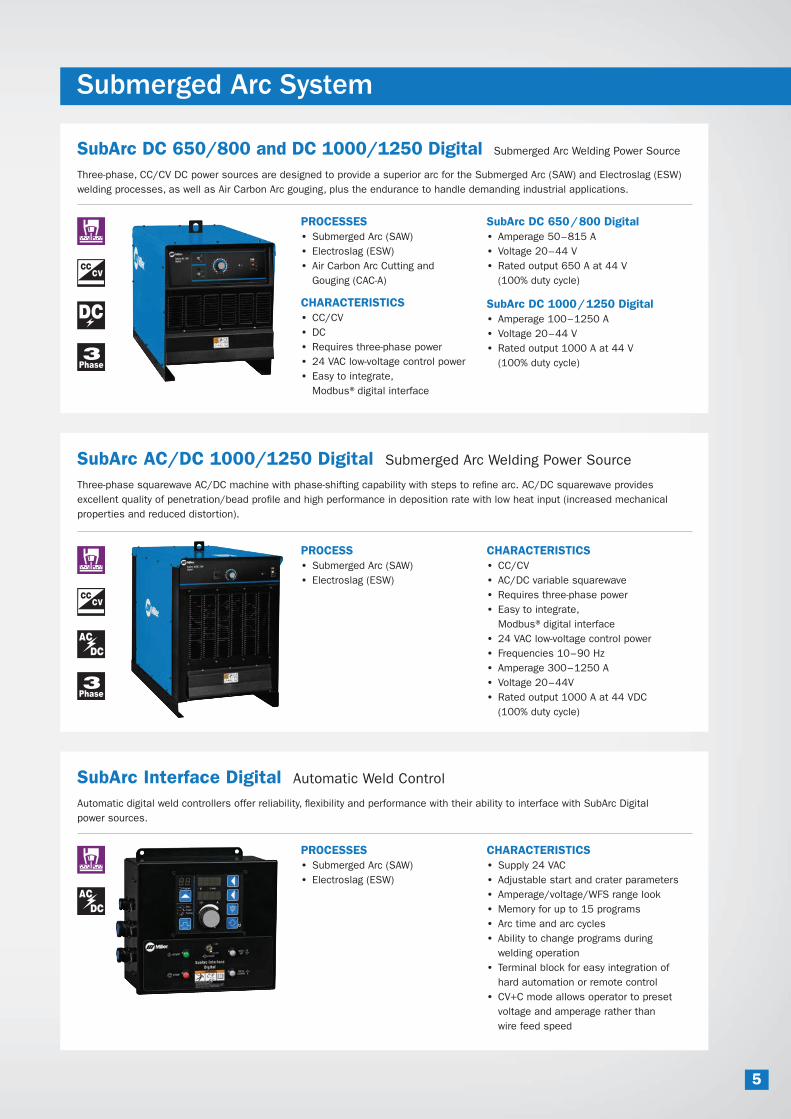
Submerged Arc System
SubArc DC 650/800 and DC 1000/1250 Digital Submerged Arc Welding Power Source
Three-phase, CC/CV DC power sources are designed to provide a superior arc for the Submerged Arc (SAW) and Electroslag (ESW)
welding processes, as well as Air Carbon Arc gouging, plus the endurance to handle demanding industrial applications.
PROCESSES
• Submerged Arc (SAW)
• Electroslag (ESW)
• Air Carbon Arc Cutting and
Gouging (CAC-A)
CHARACTERISTICS
• CC/CV
• DC
• Requires three-phase power
• 24 VAC low-voltage control power
• Easy to integrate,
Modbus®digital interface
SubArc AC/DC 1000/1250 Digital Submerged Arc Welding Power Source
Three-phase squarewave AC/DC machine with phase-shifting capability with steps to re�ne arc. AC/DC squarewave provides
excellent quality of penetration/bead pro�le and high performance in deposition rate with low heat input (increased mechanical
properties and reduced distortion).
PROCESS
• Submerged Arc (SAW)
• Electroslag (ESW)
CHARACTERISTICS
• CC/CV
• AC/DC variable squarewave
• Requires three-phase power
• Easy to integrate,
Modbus®digital interface
• 24 VAC low-voltage control power
• Frequencies 10–90 Hz
• Amperage 300–1250 A
• Voltage 20–44V
• Rated output 1000 A at 44 VDC
(100% duty cycle)
SubArc Interface Digital Automatic Weld Control
Automatic digital weld controllers offer reliability, �exibility and performance with their ability to interface with SubArc Digital
power sources.
PROCESSES
• Submerged Arc (SAW)
• Electroslag (ESW)
CHARACTERISTICS
• Supply 24 VAC
• Adjustable start and crater parameters
• Amperage/voltage/WFS range look
• Memory for up to 15 programs
• Arc time and arc cycles
• Ability to change programs during
welding operation
• Terminal block for easy integration of
hard automation or remote control
• CV+C mode allows operator to preset
voltage and amperage rather than
wire feed speed
SubArc DC 650/800 Digital
• Amperage 50–815 A
• Voltage 20–44 V
• Rated output 650 A at 44 V
(100% duty cycle)
SubArc DC 1000/1250 Digital
• Amperage 100–1250 A
• Voltage 20–44 V
• Rated output 1000 A at 44 V
(100% duty cycle)
5
SAW Accessories
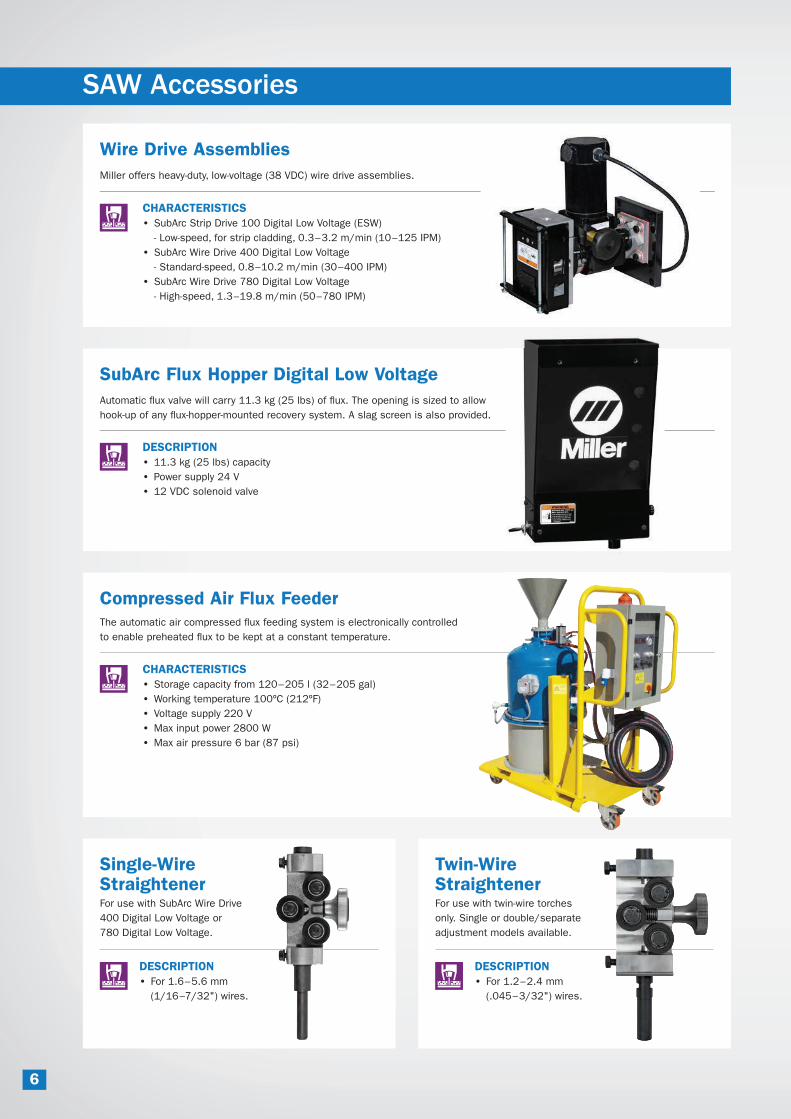
Wire Drive Assemblies
Miller offers heavy-duty, low-voltage (38 VDC) wire drive assemblies.
CHARACTERISTICS
• SubArc Strip Drive 100 Digital Low Voltage (ESW)
- Low-speed, for strip cladding, 0.3–3.2 m/min (10–125 IPM)
• SubArc Wire Drive 400 Digital Low Voltage
- Standard-speed, 0.8–10.2 m/min (30–400 IPM)
• SubArc Wire Drive 780 Digital Low Voltage
- High-speed, 1.3–19.8 m/min (50–780 IPM)
SubArc Flux Hopper Digital Low Voltage
Automatic !ux valve will carry 11.3 kg (25 lbs) of !ux. The opening is sized to allow
hook-up of any !ux-hopper-mounted recovery system. A slag screen is also provided.
DESCRIPTION
• 11.3 kg (25 lbs) capacity
• Power supply 24 V
• 12 VDC solenoid valve
Compressed Air Flux Feeder
The automatic air compressed !ux feeding system is electronically controlled
to enable preheated !ux to be kept at a constant temperature.
CHARACTERISTICS
• Storage capacity from 120–205 l (32–205 gal)
• Working temperature 100ºC (212ºF)
• Voltage supply 220 V
• Max input power 2800 W
• Max air pressure 6 bar (87 psi)
Single-Wire Straightener
Twin-Wire Straightener
For use with SubArc Wire Drive
400 Digital Low Voltage or
780 Digital Low Voltage.
For use with twin-wire torches
only. Single or double/separate
adjustment models available.
DESCRIPTION
• For 1.6–5.6 mm
(1/16–7/32") wires.
DESCRIPTION
• For 1.2–2.4 mm
(.045–3/32") wires.
6

Submerged Arc Torches System
OBT 600
600-amp,
100% duty cycle
torch with
concentric
!ux !ow nozzle.
PROCESS
• Submerged Arc
(SAW)
• Wire diameter
1.6–5.6 mm
(1/16–7/32")
OBT 1200
1200-amp,
100% duty cycle
torch with
concentric
!ux !ow nozzle.
PROCESS
• Submerged Arc
(SAW)
• Wire diameter
1.6–5.6 mm
(1/16–7/32")
Single-Wire Narrow Gap Torch
1200-amp, 100% duty cycle
torch for narrow gap.
PROCESS
• Submerged Arc (SAW)
• Wire diameter 2.4–4.0 mm
(3/32–5/32")
• For depth 50–350 mm (2–14")
• PTFE insulation
up to 200°C (390ºF)
• Ceramic insulation
up to 350°C (660ºF)
1200-Amp Single-Wire Torch —Short1200-amp, 100% duty cycle torch.
PROCESS
• Submerged Arc (SAW)
• Wire diameter 1.6–4.0 mm
(1/16–5/32")
Short model: single-wire welding nozzle
with an effective length of 220 mm (5.6").
1200-Amp Twin-Wire Torch — Short/Long
1200-amp, 100% duty cycle twin-wire
torches with concentric !ux !ow nozzle.
PROCESS
• Submerged Arc (SAW twin)
• Wire diameter 1.2–2.4 mm
(.045–3/32")
Short model: twin-arc welding torch
with an effective length of 220 mm (8.7").
Long model: twin-arc welding torch
with an effective length of 360 mm (14.2").
Tandem-Wire Narrow Gap Torch
800-amp, 100% duty cycle
torch for narrow gap.
PROCESS
• Submerged Arc (SAW)
• Wire diameter 2.4–4.0 mm
(3/32–5/32")
• For depth 50–350 mm (2–14")
• PTFE insulation
up to 200°C (390ºF)
• Ceramic insulation
up to 350°C (660ºF)
Single-Wire Narrow Gap Flat Torch
800-amp, 100% duty cycle
torch for narrow gap.
PROCESS
• Submerged Arc (SAW)
• Wire diameter 2.4–4.0 mm
(3/32–5/32")
• For depth 100–250 mm
(4–10")
• Ceramic insulation
up to 350°C (660ºF)
7

Cladding Heads
120 mm Cladding Head
CHARACTERISTICS
• Max current 3600 A
(100% duty cycle)
• Dimension
230 x 230 x 470 mm
(8 x 9 x 19")
• Weight 25 kg (55 lbs)
• Water cooled
• Strip width 60 – 90 – 120 mm
(2-3/8 – 3-1/2 – 4-3/4")
12" Diameter Head
CHARACTERISTICS
• Minimum inside
diameter pipe clad
310 mm (12")
• Max current
1000 A
(100% duty cycle)
• Dimension
1349 x 240 x 225 mm
(58-1/8 x 9-1/2 x 9")
• Weight 27.5 kg (61 lbs)
• Water cooled
• Strip width 30 mm (1-3/16")
90 mm Cladding Head
CHARACTERISTICS
• Max current 3000 A
(100% duty cycle)
• Dimension
220 x 230 x 400 mm
(8 x 9 x 16")
• Weight 19 kg (41.8 lbs)
• Water cooled
• Strip width 30 – 60 – 90 mm
(1-3/16 – 2-3/8 – 3-1/2")
10" Diameter Head
CHARACTERISTICS
• Minimum inside
diameter pipe clad
260 mm (10")
• Max current 850 A
(100% duty cycle)
• Dimension
1349 x 200 x 200 mm
(58-1/8 x 8 x 8")
• Weight 27 kg (60 lbs)
• Water cooled
• Strip width 30 mm
(1-3/16")
60 mm Cladding Head
CHARACTERISTICS
• Max current 2000 A
(100% duty cycle)
• Dimension
200 x 230 x 360 mm
(8 x 9 x 14")
• Weight 13.5 kg (29.7 lbs)
• Water cooled
• Strip width 30–60 mm
(1-3/16–2-3/8")
8" Diameter Head
CHARACTERISTICS
• Minimum inside diameter pipe clad 203 mm (8")
• Max current 750 A (100% duty cycle)
• Dimension 1349 x 150 x 150 mm
(58-1/8 x 6 x 6")
• Weight 26.5 kg (59 lbs)
• Water cooled
• Strip width 30 mm (1-3/16")
For Standard Application
It is recommended that all cladding SAW/ESW heads are used in
conjunction with the SubArc Strip Drive 100 Digital Low Voltage.
For Nozzle and Pipe Application
The following head is designed for SAW/ESW,
both circumferential and longitudinal cladding.
8
Accessories
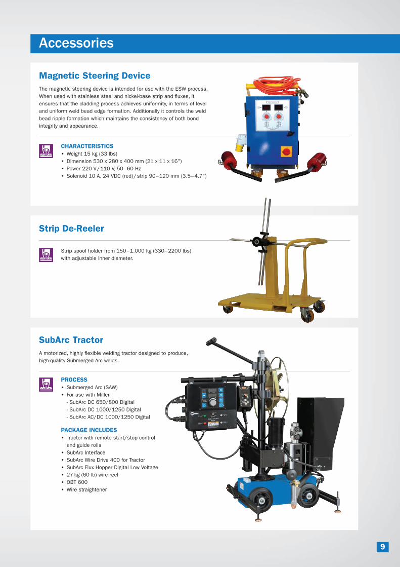
Magnetic Steering Device
The magnetic steering device is intended for use with the ESW process.
When used with stainless steel and nickel-base strip and !uxes, it
ensures that the cladding process achieves uniformity, in terms of level
and uniform weld bead edge formation. Additionally it controls the weld
bead ripple formation which maintains the consistency of both bond
integrity and appearance.
CHARACTERISTICS
• Weight 15 kg (33 lbs)
• Dimension 530 x 280 x 400 mm (21 x 11 x 16")
• Power 220 V/110 V, 50–60 Hz
• Solenoid 10 A, 24 VDC (red)/strip 90–120 mm (3.5–4.7")
Strip De-Reeler
Strip spool holder from 150–1.000 kg (330–2200 lbs)
with adjustable inner diameter.
SubArc Tractor
A motorized, highly !exible welding tractor designed to produce,
high-quality Submerged Arc welds.
PROCESS
• Submerged Arc (SAW)
• For use with Miller
- SubArc DC 650/800 Digital
- SubArc DC 1000/1250 Digital
- SubArc AC/DC 1000/1250 Digital
PACKAGE INCLUDES
• Tractor with remote start/stop control
and guide rolls
• SubArc Interface
• SubArc Wire Drive 400 for Tractor
• SubArc Flux Hopper Digital Low Voltage
• 27-kg (60 lb) wire reel
• OBT 600
• Wire straightener
9

Induction Heating
Induction heating is a proven
technology that has been used for
years in industrial and construction
applications involving welding.
Companies with welding-intensive
operations have signi�cantly increased
ef�ciency by switching to induction for
preheating before welding and stress
relieving after welding. Compared to
conventional preheating and stress
relieving methods, induction heating
offers numerous advantages.
• Low consumable costs. No fuel
costs and minimal insulation costs.
• Uniform heating is maintained along
and through the heat zone by using
induction to heat within the mate-
rial. The surface of the part is not
marred by localized conducted heat
at higher than speci�ed temperatures.
• Time-to-temperature is faster than conventional processes
due to the method of applying the heat, reducing heating
cycle time.
• Improved working environment is created during welding.
Welders are not exposed to open �ame, explosive gases
and hot elements associated with fuel gas heating and
resistance heating.
• Easy setup is achieved using preheat blankets, �exible
heating cables or the Rolling Inductor.
Magnetic �eld
Magnetic �eld
Induced Current in Part
Current in Coil
How It Works
Induction heating systems induce heat electromagnetically
rather than using a heating element in contact with a part to
conduct heat, as does resistance heating. Induction heating
acts more like a microwave oven; the appliance remains cool
while the food cooks from within.
In an industrial example of induction heating, heat is induced
in the part by placing it in a high-frequency magnetic �eld. The
magnetic �eld creates eddy currents inside the part, exciting
the part’s molecules and generating heat. Because heating
occurs slightly below the metal surface, no heat is wasted.
10

Induction Heating System
ProHeat™ Rolling Inductor Induction Heating System
The ProHeat 35 Induction Heating System with the Rolling Inductor is a simple and cost-effective heating
process that can solve many preheating problems related to moving parts and deliver fast, consistent heat.
BENEFITS
• Maximum productivity
- Quick time to temperature
- Continuous fabrication
- No coiling of cable
• Improved safety
- Eliminates open !ames
- Cooler shop environment and
reduced operator fatigue
• Optimal consistency and quality
- Even distribution of heat
eliminates quality issues
• Easy to use
- Simple setup and operation
- Flexible and portable for a
wide range of applications
ProHeat 35 Liquid-Cooled System with Rolling Inductor.
(Pipe stands sold separately.)
Rated Output
Ambient Temperature Range
Storage Usage
Maximum Part
Preheat Temperature
Required Cooler
Dimensions
Shipping
Weight
300 amps at
100% duty cycle
-40°C to 82°C
(-40°F to 180°F)
0°C to 60°C
(32°F to 140°F)
315°C (600°F) Miller Heavy-Duty
Induction Cooler
(#951 142)
H: 133 mm (5.25")
W: 168 mm (6.6")
D: 203 mm (8")
18.1 kg
(40 lbs)
Specially designed for heating moving parts.
APPLICATIONS
• Process piping
• Re&nery
• Petrochemical
• Power piping
• Pressure vessels
Rolling Inductor Speci�cations
11