STUDY OF BOUNDARY LAYER PARAMETERS ON ROUGH SURFACESethesis.nitrkl.ac.in/4178/1/10.pdf · study of...
62
1 STUDY OF BOUNDARY LAYER PARAMETERS ON ROUGH SURFACES A THESIS SUBMITTED IN PARTIAL FULFILLMENT OF THE REQUIREMENTS FOR THE DEGREE OF Bachelor of Technology in Civil Engineering By DEVESH SRIVASTAVA & ALOK PANDEY Department of Civil Engineering National Institute of Technology Rourkela 2008
-
Upload
vuonghuong -
Category
Documents
-
view
221 -
download
0
Transcript of STUDY OF BOUNDARY LAYER PARAMETERS ON ROUGH SURFACESethesis.nitrkl.ac.in/4178/1/10.pdf · study of...

1
STUDY OF BOUNDARY LAYER PARAMETERS ON ROUGH SURFACES
A THESIS SUBMITTED IN PARTIAL FULFILLMENT
OF THE REQUIREMENTS FOR THE DEGREE OF
Bachelor of Technology in
Civi l Engineering
By
DEVESH SRIVASTAVA
&
ALOK PANDEY
Department of Civ i l Engineer ing
Nat ional Ins t i tu te of Techno logy
Rourke la
2008
2
STUDY OF BOUNDARY LAYER PARAMETERS ON ROUGH SURFACES
A THESIS SUBMITTED IN PARTIAL FULFILLMENT
OF THE REQUIREMENTS FOR THE DEGREE OF
Bachelor of Technology in
Civi l Engineering
By
DEVESH SRIVASTAVA
&
ALOK PANDEY
Under the Guidance of
Dr. AWADHESH KUMAR
Department of Civ i l Engineer ing
Nat ional Ins t i tu te of Techno logy
Rourke la
2008
3
National Institute of Technology
Rourkela
CERTIFICATE
T hi s i s t o c e r t i f y t h a t t he t he s i s en t i t l ed , “S tudy o f B ound a ry
L ay e r Pa ra me t e r s on Rou gh Su rf a ce s ” s ub mi t t e d b y S ri D ev esh
S r i va s ta va a nd Sr i A lok Pand e y i n p a r t i a l fu l f i l lme n t o f t h e
r e q u i r em en t s f o r t h e a w a r d o f Ba c he l o r o f T e ch no lo gy D e gr e e i n
C i v i l En g in e e r i n g a t t h e N a t io n a l In s t i t u t e o f T e ch no lo gy, R o u r k e l a
( D e e me d Uni v e r s i t y) i s a n au th e n t i c w o r k c a r r i ed ou t by h i m un d e r
m y s u p er v i s io n a nd gu id a n ce .
T o th e b e s t o f m y k n ow le d ge , t h e m at t e r e mb od ie d in t he t h e s i s h a s
n o t b e en s ub mi t t ed t o an y o t h e r U n i v er s i t y/ In s t i t u t e fo r t h e a w a rd o f
a n y D e gr e e o r Di p lo m a.
D a t e : P ro f . A w adh e sh Kum a r
D e p t . o f C iv i l En g in e e r i n g
N a t i on a l In s t i t u t e o f T e ch no l o g y
R ou r ke l a - 76 90 08
4
National Institute of Technology
Rourkela
ACKNOWLEDGEMENT
W e w ou ld l i k e t o ex p r es s ou r s in c e r e g r a t i t ud e t o D r . A . K um a r fo r
h i s i nv a lu a b l e gu id a n c e , c oo pe r a t io n a n d co ns t a n t e nco u r a gem e n t
d u r i n g t he c ou rs e o f t h e p ro j e c t . W e a r e g r a t e f u l t o D r . K .C . P a t r a ,
H e a d o f t he d ep ar tm e n t , C iv i l E n gi n e er in g f o r g i v ing a l o t o f
f r e e do m, en c ou r a ge m e n t an d gu id a n ce . W e a r e a l s o t h an k fu l t o t h e
T e c hn i ca l S t a f f o f t h e F lu id M ec h an ics La b o r a to r y, N . I . T . R ou r ke l a
f o r h e l p i n g u s du r in g th e ex pe r im en ta l wo rk .
D e v es h S r i va s ta va A lok Pand e y
D e pt . o f C iv i l En g in e e r i n g D ep t . o f C iv i l Eng i n e e r i n g
N . I . T Ro u rk e l a N . I . T R ou rk e l a

i
CONTENTS
Chapter 1 GENERAL INTRODUCTION 1 . 1 In t ro du c t io n 1
Chapter 2 CONCEPTS OF BOUNDARY LAYER
2 . 1 D e f i n i t i o n o f T h i ck n es s 5
2 . 2 E f f e c t o f P re s s u re G r a d i e n t 6
2 . 3 R ou gh Su r f a c es 7
Chapter 3 TEMPERATURE EFFECTS 3 .1 Effec t on Ai r Dens i t y 9
3 .2 Effec t on Kinemat i c Vi scos i t y 10
Chapter 4 TEST APPARATUS
4 .1 Air Flow Bench AF10a 12
4 .2 In t roduct ion 13
4 .3 Descr ip t ion 13
4 .4 Mul t i tube Manometer 14
4 .5 Boundary Layer Apparatus AF14 17
Chapter 5 TEST PROCEDURE
5 .1 Procedure 19
Chapter 6 OBSERVATIONS & CALCULATIONS 21
CONCLUSION 52
REFERENCES 53

ii
ABSTRACT
When real fluid flows past a solid body or a solid wall, the fluid particles adhere
to the boundary and condition of no slip occurs. This means that the velocity of fluid
close to the boundary will be same as that of boundary. If the boundary is stationary, the
velocity of fluid at the boundary will be zero. Further away from the boundary, the
velocity will be higher and as a result of this variation of velocity, the velocity gradient
will exist. The velocity of fluid increases from zero velocity on the stationary boundary to
the free stream velocity of the fluid in the direction normal to the boundary. This
variation of velocity from zero to free stream velocity in the direction normal to the
boundary takes place in a narrow region in the vicinity of solid boundary. This narrow
region of fluid is called Boundary Layer.
Three main parameters (described below) that are used to characterize the size
and shape of a boundary layer are the boundary layer thickness, the displacement
thickness, and the momentum thickness.
The displacement thickness is the distance a streamline just outside the boundary
layer is displaced away from the wall compared to the inviscid solution. Another way to
describe it is the distance the wall would have to be displaced to yield the same solution
for flow outside the boundary layer as the boundary layer equations yield.
The momentum thickness, is the distance that, when multiplied by the square of
the free-stream velocity, equals the integral of the momentum defect across the boundary
layer.
In our thesis, we have obtained the boundary layer parameters and velocity ratio
on smooth and different types of rough surfaces by using Air Flow Bench. The sand
papers of different grain sizes have been considered as rough surfaces.
iii
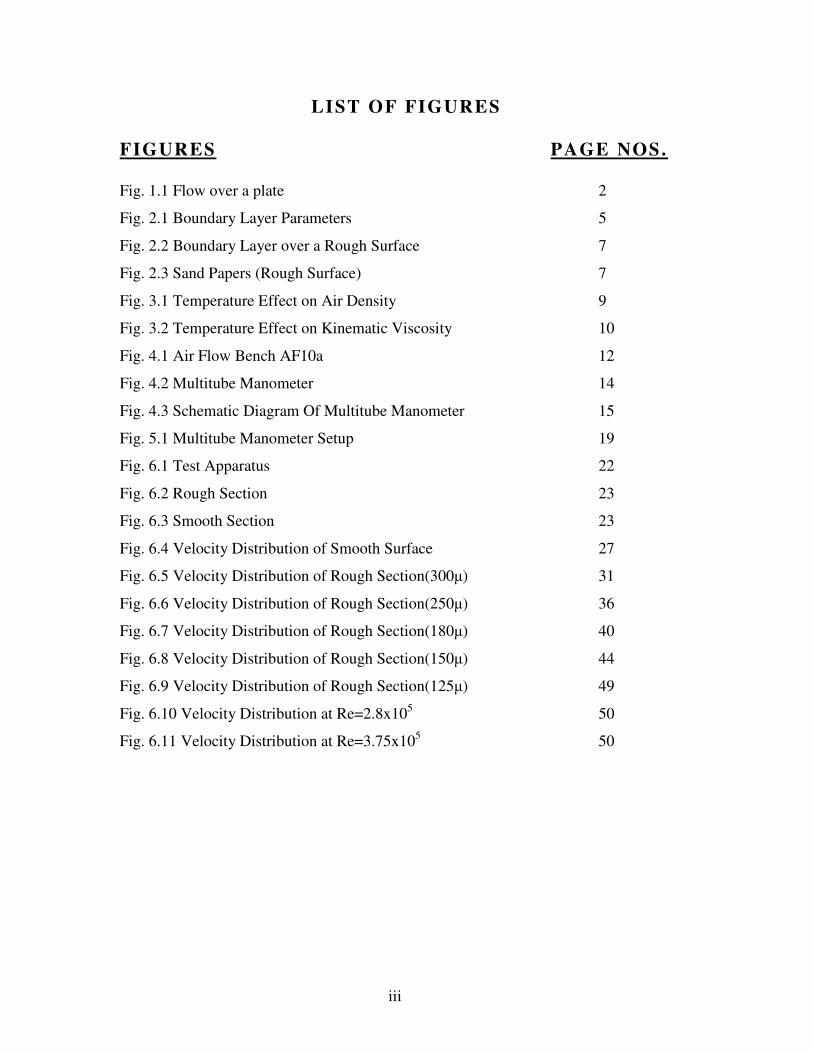
LIST OF FIGURES
FIGURES PAGE NOS.
Fig. 1.1 Flow over a plate 2
Fig. 2.1 Boundary Layer Parameters 5
Fig. 2.2 Boundary Layer over a Rough Surface 7
Fig. 2.3 Sand Papers (Rough Surface) 7
Fig. 3.1 Temperature Effect on Air Density 9
Fig. 3.2 Temperature Effect on Kinematic Viscosity 10
Fig. 4.1 Air Flow Bench AF10a 12
Fig. 4.2 Multitube Manometer 14
Fig. 4.3 Schematic Diagram Of Multitube Manometer 15
Fig. 5.1 Multitube Manometer Setup 19
Fig. 6.1 Test Apparatus 22
Fig. 6.2 Rough Section 23
Fig. 6.3 Smooth Section 23
Fig. 6.4 Velocity Distribution of Smooth Surface 27
Fig. 6.5 Velocity Distribution of Rough Section(300µ) 31
Fig. 6.6 Velocity Distribution of Rough Section(250µ) 36
Fig. 6.7 Velocity Distribution of Rough Section(180µ) 40
Fig. 6.8 Velocity Distribution of Rough Section(150µ) 44
Fig. 6.9 Velocity Distribution of Rough Section(125µ) 49
Fig. 6.10 Velocity Distribution at Re=2.8x10⁵
50
Fig. 6.11 Velocity Distribution at Re=3.75x10⁵
50
iv
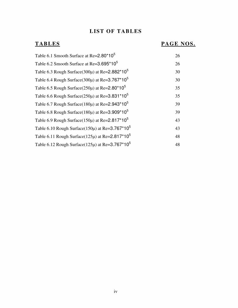
LIST OF TABLES
TABLES PAGE NOS.
Table 6.1 Smooth Surface at Re=2.80*105
26
Table 6.2 Smooth Surface at Re=3.695*105 26
Table 6.3 Rough Surface(300µ) at Re=2.882*105 30
Table 6.4 Rough Surface(300µ) at Re=3.767*105 30
Table 6.5 Rough Surface(250µ) at Re=2.80*105 35
Table 6.6 Rough Surface(250µ) at Re=3.831*105 35
Table 6.7 Rough Surface(180µ) at Re=2.943*105 39
Table 6.8 Rough Surface(180µ) at Re=3.909*105 39
Table 6.9 Rough Surface(150µ) at Re=2.817*105 43
Table 6.10 Rough Surface(150µ) at Re=3.767*105 43
Table 6.11 Rough Surface(125µ) at Re=2.817*105 48
Table 6.12 Rough Surface(125µ) at Re=3.767*105 48

1
CHAPTER 1
INTRODUCTION

2
INTRODUCTION
W h e n a r e a l f l u i d f l ow s o v e r a s o l i d s u r fa c e , t h e r e i s no s l i p a t t he
s u r fa c e . Th e f l u i d i n t h e im m edi a t e c o n t ac t wi t h a s u r f a c e m ov es
w i t h i t , an d th e r e l a t i v e v e l o c i t y i n c re a s e s f rom z e ro a t t h e su r f a ce
t o t h e v e l oc i t y i n t h e f r e e s t r e am t h r ou gh a l a ye r o f f l u id w h i c h i s
c a l l e d Bou nd a r y La ye r .
T h e b ou nd ar y l a y er e f f e c t o c c u r s a t t h e f i e ld r e g io n i n w h i c h a l l
c h a n ge s o cc u r i n t h e f l o w p a t t e r n . T h e bo un d ar y l a ye r d i s t o r t s
s u r ro un d in g n on v i sc o us f l o w. I t i s a p h en om e no n o f v i sc o us f o r c e s .
T h i s e f f e c t i s r e l a t e d t o t h e Re yn o l ds n um b er .
La m i n a r bo un d a r y l a ye r s c o m e in v a r i ou s fo rm s an d c an b e l o os e l y
c l as s i f i e d a c co r d ing t o t h e i r s t ru c t u re a n d th e c i r cum s ta n c e s u nd e r
w h ic h th e y a r e c r ea t e d . T h e th i n sh ea r l a ye r w h i ch d e ve l op s on an
o s c i l l a t i n g b od y i s a n ex a mpl e o f a S t ok e s l a ye r , w h i l e t h e B l as ius
b o un da r y l a ye r r e f e r s t o t h e w e l l -k now n s imi l a r i t y s o l u t i on fo r t h e
s t ea d y b o u nd a r y l a ye r a t t a c h e d t o a f l a t p l a t e h e l d i n an o n com in g
u n i d i r e c t i on a l f l ow.
F i g . 1 .1
C on s id e r a s t ea d y f l o w o ve r a f l a t smo o t h p l a t e w h e re t he s t r e am in g
v e lo c i t y U i s co ns t a n t ov e r t he l e n g th o f t he p l a t e . I t i s f o un d th a t
t h e t h i ck ne ss o f t he b ou nd a r y l a ye r g r o w s a l on g th e l en g t h o f t h e
p l a t e a s sh ow n a bov e .
T h e m ot i on i n t h e b o un da r y l a ye r i s l a mi n a r a t t h e s t a r t , bu t i f t he
p l a t e i s s u f f i c i en t ly l o n g , a t r a ns i t i on t o t u r bu l e n c e i s o bs e rv e d .
T h i s t r a ns i t i on i s p r od u c ed b y s m a l l d i s tu r b an c es w h i ch , b e yo n d a

3
c e r t a i n d i s t an c e , g ro w s r a p id l y a n d me r ge t o p ro du c e th e a p pa r e n t l y
r a n dom f l u c tu a t ion s o f v e l o c i t y w h ic h a r e ch a r a c t e r i s t i c s o f
t u rb u l en t m o t i on s .
T h e p a ra m et e r wh ic h c h a r a c t e r i z es t he m ot io n i s t h e R e x b a s ed on
d i s t a n c e x f ro m t h e l e ad i n g ed ge .
R e x = U x
ν
T h e n a t u re o f t h e p r o c es s o f t r an s i t i o n r e nd e rs i t p ro ne to f a c to r s
s u ch as t u rb u l en c e i n t h e f r e e s t r e am a n d su r f a c e r ou ghn e ss o f t h e
b o un da r y, s o i t i s n o t p os s i b l e t o g i v e a s in g l e va lu e o f R e x a t
w h ic h t r an s i t i on wi l l o c cu r , b u t i t i s u su a l l y f o u n d in t h e r an ge o f
1x 10⁵
t o 5x 10⁵.
In t h i s p r o j e c t , w e w o u l d s tu d y t h e e f fe c t o f su r f a c e ro u gh n es s on
d i f f e r en t bo un d ar y l a ye r p a r am et e r s . Th i s w ou ld b e a t t a i ne d b y
u s i n g s a nd p ap e r s o f v a r i ou s g r a in s i z e s .
T he ex t ens iv e ex pe r im e n t a t i on o n d i f f e r e n t r ou gh s u r fa ce s wi l l
e n a b l e us t o s tu d y t h e ch a n ges i n bo und a r y l a ye r p a r am e te r s f r om
s mo ot h t o r ou gh s u r f a c e s . I t w i l l h e l p i n t h e a s s e s sm e n t o f t h e
b o un da r y l a ye r c h ar a c t e r i s t i c s f o r a g iv e n r ou gh n ess . T h i s m a y b e
u s ed i n a e ro d yn a m ic d es i gn .

4
CHAPTER 2
CONCEPTS OF BOUNDARY LAYER

5
CONCEPTS OF BOUNDARY LAYER
2 .1 DEFINITION OF THICKNESS
A l i t t l e c o ns i d e ra t i o n sh o ws th a t t h e b o un da r y l a ye r t h i c k n es s δ , a s
t h e t h i c kn es s w h ere t h e v e l o c i t y r e a c h e s t h e f r e e s t r e am v a l u e , i s
n o t a n e n t i r e l y s a t i s fa c to r y c o n c e p t . T h e v e l oc i t y i n t he b o un d a r y
l a ye r i n c r e as es t o wa r d s U i s a n as ym pt o t i c m an ne r , s o t he d i s t a n c e y
a t w h i ch w e mi gh t c o ns i d e r t he v e lo c i t y t o h a v e r e a ch e d U wi l l
d e p en d on t he a c cu r a c y o f m ea su r em en t .
A m u ch mo r e u se f u l c on c e p t o f t h i ck n ess i s t h e d i sp l a c em e n t
t h i ck n es s δ* . T h i s i s d e f in e d a s t h e t h i c kn es s b y w h i ch f l u id o u t s id e
t h e l a ye r i s d i s p l ac e d a w a y f r o m t he b o un d a r y b y t h e ex i s t e n c e o f
t h e l a ye r , b y t h e s t r e a ml i n e a pp r oa c h in g B in t h e f i gu re .
H e r e , t h e d i s t r i bu t io n o f v e l o c i t y u w i t h i n t he l a ye r i s d e p i c t ed a s a
f u n c t i on o f d i s t an ce y f r o m t he bo un da r y a s c u r v e O A. I f t he r e w as
n o bo un d ar y l a ye r , t h e f r ee s t r e am ve l o c i t y U w o u ld pe r s i s t r i gh t
d o wn t o t h e bo un d ar y ( C A ) .
F i g . 2 . 1

6
2 .2 EFFECT OF PRESSURE GRADIENT
I f t h e f r e e s t r e am i s a c ce l e r a t i n g o r d ec e l e r a t i n g , s ub s t an t i a l
c h a n ge s t ak e p l a ce i n t h e bo un d ary l a ye r d e v e lo pme n t . Fo r a n
a c c e l e ra t i n g f r e e s t r e a m, t h e p r e s s u re f a l l s i n t h e d i r e c t i o n o f f l o w,
t h e p r es su r e g r ad i e n t b e i n g g iv e n by d i f f e r e n t i a t i n g Be r n ou l l i ’ s
E q ua t i on in t h e f r ee s t r e am a s ,
d P = -ρU d U
dx dx
T h e bo un d ar y l a ye r g r o w s l e s s r a p id l y t h an in z e r o p r es su r e g r a d i e n t
a n d t r a ns i t i o n t o t u r bu le n c e i s i nh ib i t e d . Fo r t h e de c e l e r a t i n g f r e e
s t r e a m, t h e r ev e r s e e f f e c t s a r e o bs e r ve d . Th e bo un d ar y l a ye r g r o w s
m o re r a p id l y a n d t h e sh a p e f a c to r i n c r e as e s i n t h e do w n s t r e am
d i re c t io n .
T h e p r es su r e r i s e s i n t h e d i r ec t i on o f f l o w , a nd t h i s p r e s su r e r i s e
t e nd s t o r e t a rd t he f l u id i n t h e b ou nd a r y l a ye r m o r e s ev e r e l y t h a n
t h a t i n t h e m ain s t r e a m s i n c e i t i s m ov in g l e s s q u i ck l y. E n e r g y
d i f f us e s f rom t he f r e e s t r e a m t h ro u gh t h e ou t e r p a r t o f t h e b ou nd a r y
l a ye r d o w n t ow a r ds t h e su r f a c e t o ma i n t a i n t he f o rw a rd mo v em en t
a ga i ns t t h e r i s i n g p r e s su r e .
H o w ev e r , i f t h e p re s su r e g r ad i e n t i s su f f i c i e n t l y s t e e p , t h e d i f f us io n
i s i n s u f f i c i en t t o su s t a i n t h e fo r w a rd m ov em e n t , an d t h e f l o w a lo n g
t h e su r f ac e r ev e r s es , f o rc in g th e m ain s t r e am to s e p ar a t e .
I t i s t h i s s e p ar a t i on , o r s t a l l a s i t i s s om et im es c a l l e d , w h ic h l ea ds
t o t h e m ai n co mp on e n t o f d r a g o n b lu f f b od ie s a nd t o t he c o l l ap s e o f
t h e l i f t fo r c e on a n a e r o fo i l w hen t h e an g l e o f i n c id e nc e i s
ex c e s s i v e .

7
2 .3 ROUGH SURFACES
Fig. 2.2
T o a c co un t f o r ro u gh ne ss w e f i r s t d e f i n e a n ‘e qu iv a l en t s a n d
r o u ghn e ss ’ c o ef f i c i e n t k (u n i t s : [ L] ) , a m e a su r e o f t h e ch a r a c t e r i s t i c
r o u ghn e ss h e i gh t .
T h e p a r am et e r t h a t d e t e rm in e s t h e s i gn i f i c an c e o f t h e r ou gh n es s k i s
t h e r a t i o
k
δ
Fig. 2.3

8
CHAPTER 3
TEMPERATURE EFFECTS
9
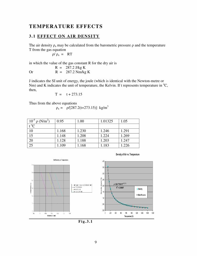
TEMPERATURE EFFECTS
3 .1 EFFECT ON AIR DENSITY
The air density ρa may be calculated from the barometric pressure ρ and the temperature
T from the gas equation
ρ/ ρa = RT
in which the value of the gas constant R for the dry air is
R = 287.2 J/kg K
Or R = 287.2 Nm/kg K
J indicates the SI unit of energy, the joule (which is identical with the Newton-metre or
Nm) and K indicates the unit of temperature, the Kelvin. If t represents temperature in oC,
then,
T = t + 273.15
Thus from the above equations
ρa = ρ/[287.2(t+273.15)] kg/m3
10-5
ρ (N/m2) 0.95 1.00 1.01325 1.05
t oC
10 1.168 1.230 1.246 1.291
15 1.148 1.208 1.224 1.269
20 1.128 1.188 1.203 1.247
25 1.109 1.168 1.183 1.226
F i g . 3 . 1
10
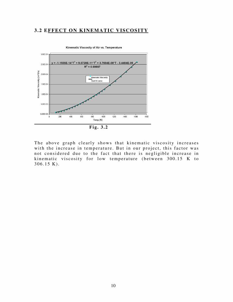
3 .2 EFFECT ON KINEMATIC VISCOSITY
F i g . 3 .2
T h e a bo ve g r a p h c l e a r l y s h o ws th a t k i ne m at i c v i s c os i t y i n c r e a s es
w i t h t h e i n c r e a s e i n t em p er a tu r e . Bu t i n ou r p ro j e c t , t h i s f a c to r w as
n o t co ns id e r ed d u e to t h e f a c t t h a t t h e r e i s ne g l i g i b l e i n c r e a s e in
k in em a t i c v i s c os i ty f o r l o w t emp e ra t u r e ( b e t w ee n 300 . 15 K t o
3 0 6 . 15 K ) .

11
CHAPTER 4
TEST APPARATUS

12
TEST APPARATUS
The apparatus used was AIR FLOW BENCH AF10a.
4 .1 AIR FLOW BENCH AF10a
F ig . 4 .1

13
4 .2 INTRODUCTION
This equipment was devised by Professor E. Markland, former Head of
Department of Mechanical Engineering, University of Cardiff, for an introductory course
in Air Flow.
4 .3 DESCRIPTION
AF10 Airflow Bench is in the nature of a simple miniature wind tunnel; it
provides a controlled airstream for experiments which use matching test equipment.
The AF10 Airflow Bench comprises a fan which draws air from the atmosphere
and delivers it along a pipe to an airbox which is above the test area. In the pipe is a valve
which may be used to regulate the discharge from the fan.
There is a rectangular slot in the underside of the airbox to which various
contraction sections may be fitted. The air accelerates as it flows from the box along the
contracting passage, and any unsteadiness or unevenness of the flow at the entry becomes
proportionately reduced as the streaming velocity increases towards the test section,
which is fitted at the exit of the contraction. Discharge from the test section is in most
cases directed towards the bench top, in which a circular hole is provided to collect the
air so that it may be led through a duct to the rear of the bench. If necessary, the exhaust
can be taken right out of the laboratory (for example, if, use is to be made of smoke
traces) with the exhaust duct extended as necessary and an extractor fan fitted at the
downstream end if required.
The bench is mounted on wheels with jacking screws so that it may be moved
without difficulty. It requires an earthed, AC single-phase electrical supply.
A fan delivers atmospheric air via an iris valve to a plenum chamber. The iris
valve is used for flow control. Various test facilities may be attached to a 350mm x
300mm opening in the plenum chamber. An aerodynamically shaped contraction is
supplied with the bench to provide an entry to a number of experiments, having 100mm x
50mm working section. Extensive use is made of toggle fasteners so that no tools are

14
required for fitting the various experiments to the bench. Discharge from the experiments
is normally downwards, the exhaust air passing through a pipe let into the bench top and
terminating at the rear. This arrangement allows flexible ducting to be fitted (when
experiments using smoke are in progress) to lead waste smoke safely away.
4.4 THE INCLINABLE MULTITUBE MANOMETER (AF10A)
Fig. 4.2

15
Fig. 4.3
The reservoir for the manometer liquid is mounted on a vertical rod so that it may
be set to a convenient height. It is recommended that the manometer tubes at the two
sides, marked A in above figure, and the reservoir connection, be normally left open to
atmospheric pressure. Pressures p1, p2, p3 ... in tubes 1, 2, 3 are then gauge pressures,
measured relative to an atmospheric datum. (Pressures relative to some other datum may
be obtained by connecting the reservoir and the manometer tubes marked A to the
required datum).
The usual manometer liquid is water, although in some instances a paraffin-based
liquid of low specific gravity is used. To aid visibility, the water may be coloured by a
dye which is supplied with the equipment. The specific gravity of the water is not
significantly altered by addition of the dye. To fill, the reservoir is positioned about
halfway up the bar, and the fitting at the top is unscrewed. Using the funnel provided,
manometer liquid is poured in until the level is halfway up the scale. Any air bubbles
from the manometer tubes are then removed by tapping the inlet pipe, or by blowing into
the tops of the tubes.

16
The manometer scale is usually graduated in mm. Pressure readings taken in
terms of mm of water may be converted to units of millibar (mb) from the relationship:
1 mm water = 0.0981 mb (1mb=100 Pa)
∆p = p-pa
The manometer must be levelled before taking readings. This can be done by
using the adjustable feet, while observing the spirit level and the manometer liquid levels
across all of the tubes under static conditions.
It is possible that, as the air speed is increased, liquid may be driven out of the
tops of the manometer tubes, or drawn down into the manifold at the base. The
connection between tapping points and the manometer would then have to be cleared, or
the reservoir may need to be refilled. It is therefore advisable, before starting a test, to
guard against these eventualities by adopting the following setting-up procedure.
With the fan at rest and the bench valve closed, the manometer should be set to
the vertical position, with the liquid level at about mid-height. The fan should then be
started, and the air speed raised gradually by carefully opening the bench valve, while
observing the levels in the manometer tubes. As the pressures in the various tubes
change, the reservoir level should be moved up or down, as found to be necessary to keep
all the liquid levels within the bounds of the scale. A good setting would use most of the
scale at full airspeed. If, however, only a small proportion of the scale is used, the
procedure should be repeated with the manometer inclined to the vertical.
To fill the manometer position the reservoir approximately halfway up the side
bar. Unscrew the fitting on top of the reservoir and, using the funnel provided, pour in a
quantity of water (and dye if required). Continue until the water level is halfway up the
manometer scale. Check the system for air bubbles, and remove by tapping the inlet pipe,
or by gently blowing into the manometer tube at the top.
Having decided on a suitable manometer setting, a final height adjustment of the
reservoir should then be made to bring the datum reading at tubes A to some convenient

17
scale graduation - such as, for example, 120 mm. This is the value which has to be
subtracted from the scale readings of the pressures p1, p2... to obtain gauge pressures. It
is much easier to perform the subtraction with a datum that has been conveniently
chosen.
4 .5 BOUNDARY LAYER APPARATUS AF14.
A f l a t p l a t e i s p l ac e d i n t h e l 00 mm x 50m m t ra ns p a re n t w o rk i n g
s e c t io n so t ha t a bo u nd a r y l a ye r f o r ms a l on g i t . A s e ns i t i v e , w ed ge
s h ap e d p i to t t u be m ou n t ed in a mi c ro m et e r t r a v e r s e a l l o w s v e l o c i t y
m e as u r em en t s t o be m a de in t h e b oun d a r y l a ye r . Bo t h l am in a r an d
t u rb u l en t l a ye r s ma y b e f o r m ed . Ex pe r im e n t s wh ic h m ay b e c a r r i ed
o u t i nc lu d e t h e m eas u r em en t o f t h e ve lo c i t y p r o f i l e :
1 . In l a mi na r an d tu r bu le n t b ou nd a r y l a ye r s .
2 . In t h e b ou nd a r y l a ye r o n r ou gh an d s mo o t h p l a t es .
3 . In t h e b ou nd a r y l a ye r a t v a r io us d i s t an c e s f r om th e l e a d in g e d ge
o f t he p l a t e .
4 . In t he bo un d ary l a ye r o n p l a t es s ub i e c t t o an i nc r e a s i n g o r
d e c r e as in g p r es su re g r a d i en t i n t h e d i re c t i o n o f f l o w ( u s i n g t h e
r e mo v ab l e du c t l i ne r s s up p l i e d ) .
D I ME NS IO NS & W EI GHTS
AF10
Dimension: 11 00 x 10 0 0 x 22 10m m
Weight: 1 20 k g Gro ss : 2 . 43m3; 26 0k g .
A F1 4
Dimension: 0.2m3
Weight:10kg

18
CHAPTER 5
TEST PROCEDURE
19
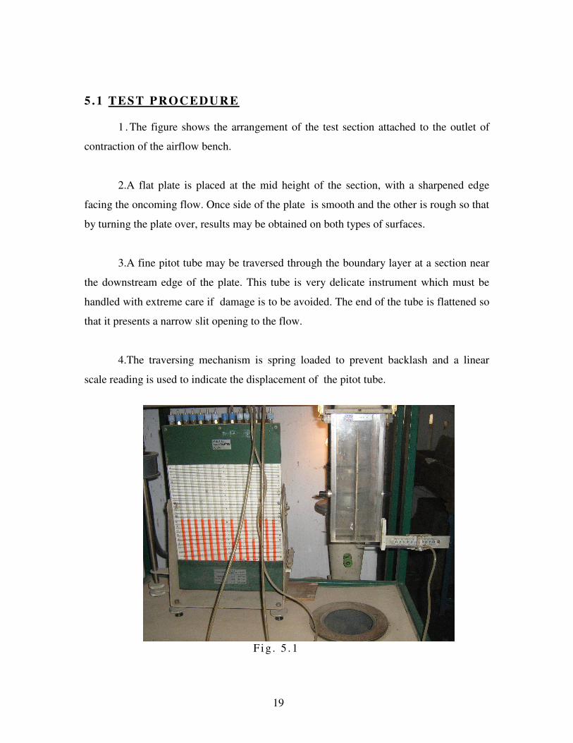
5 .1 TEST PROCEDURE
1 . The figure shows the arrangement of the test section attached to the outlet of
contraction of the airflow bench.
2.A flat plate is placed at the mid height of the section, with a sharpened edge
facing the oncoming flow. Once side of the plate is smooth and the other is rough so that
by turning the plate over, results may be obtained on both types of surfaces.
3.A fine pitot tube may be traversed through the boundary layer at a section near
the downstream edge of the plate. This tube is very delicate instrument which must be
handled with extreme care if damage is to be avoided. The end of the tube is flattened so
that it presents a narrow slit opening to the flow.
4.The traversing mechanism is spring loaded to prevent backlash and a linear
scale reading is used to indicate the displacement of the pitot tube.
F i g . 5 . 1
20
5 . To obtain a boundary layer velocity profile, the pitot tube was set touching the
smooth surface of the plate and the wind speed is established by bringing the pressure Po
in the air box to the required value. Readings of total pressure P measured by pitot tube
are then recorded over a range of settings of the linear scale as the tube is traversed
towards the test section surface.
6.Similarly, readings were taken on a smooth surface followed by five different
rough surfaces of grain sizes 300 microns, 250 microns, 180 microns, 150 microns & 125
microns.

21
CHAPTER 6
OBSERVATIONS & CALCULATIONS
22
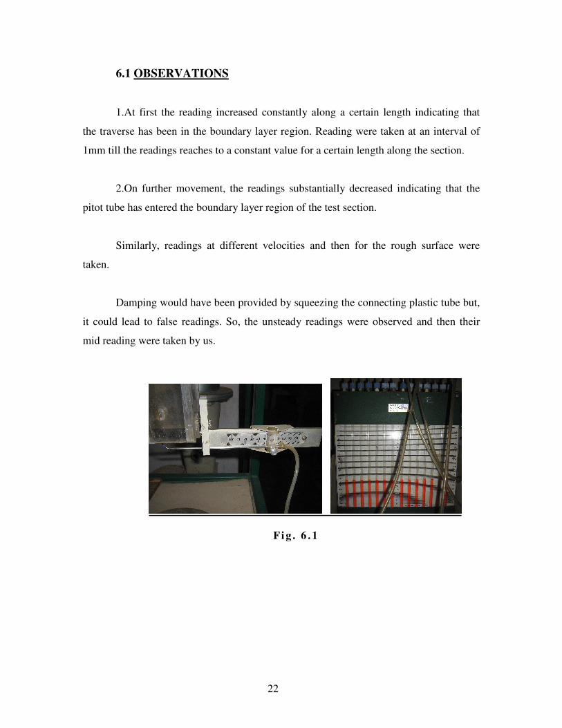
6.1 OBSERVATIONS
1.At first the reading increased constantly along a certain length indicating that
the traverse has been in the boundary layer region. Reading were taken at an interval of
1mm till the readings reaches to a constant value for a certain length along the section.
2.On further movement, the readings substantially decreased indicating that the
pitot tube has entered the boundary layer region of the test section.
Similarly, readings at different velocities and then for the rough surface were
taken.
Damping would have been provided by squeezing the connecting plastic tube but,
it could lead to false readings. So, the unsteady readings were observed and then their
mid reading were taken by us.
F i g . 6 . 1

23
6 . 2 ROUGH SECTION
T h e r ou gh s e c t io n c o ns i s t s o f s a nd p ap e r o f k no wn g r a i n s i z e .
F i g . 6 .2
6 .3 PLANE SECTION
I t c o n s i s t s o f a p l an e m et a l s e c t i o n .
F i g . 6 .3
24
6 .4 EXPERIMENTAL DATA
Length of plate from leading edge to traverse section, L= 0.25m.
Thickness of pitot tube at tip, 2t=0.4mm.
Hence, displacement of tube centre from surface when in contact, t=0.2mm.
Values of u/U are found from equation given below:
(u/U) = √(Pt/Po)
Where Pt is Pitot Pressure and Po is the pitot tube reading in the free stream.
The Free Stream Velocity is then obtained by the equation given below:
(1/2)ρU2 = Po
The Reynold Number is then obtained by the equation given below:
Re = UL/ν

25
6 . 5 SMOOTH SURFACE
V e lo c i t y 17 .5 3 m/ s .
Room Temperature: 33oC (306 K)
Density of air at 33oC = 1.151 kg/m
3
Air flow bench pressure (Po) = 176.8398N/mm2
The Free Stream Velocity is then obtained by the equation given below:
(1/2)ρU2 = Po
U = 17.53 m/sec.
The Reynold Number is then obtained by the equation given below:
Re = UL/ν
Re = 2.80 x 10⁵
V e lo c i t y 23 .1 1 m/s .
Room Temperature: 33oC (306 K)
Density of air at 33oC = 1.151 kg/m
3
Air flow bench pressure(Po): 307.547N/mm2
The Free Stream Velocity is then obtained by the equation given below:
(1/2)ρU2 = Po
U = 23.11 m/sec.
The Reynold Number is then obtained by the equation given below:
Re = UL/ν
Re = 3.695 x 10⁵

26
Table 6.1: Smooth Surface
Smooth Surface
Temperature=33`C Po=176.8398N/mm2
Sp. Gravity of
Manometer fluid=.784
air density at 33C=
1.151kg/m3
U=17.53m/s Reynold's
no. , Re=2.80*10
5
scale reading distance(mm) manometer reading relative
distance(cm) Pt(N/mm
2) u/U u/u(1-u/U)
39 0.2 12.1 17.1 84.575568 0.691564075 0.213303205
40 1.2 12.4 17.4 107.641632 0.780189498 0.171493845
41 2.2 12.7 17.7 130.707696 0.859726954 0.120596519
42 3.2 12.9 17.9 146.085072 0.908893259 0.082806303
43 4.2 13 18 153.77376 0.932504808 0.062939591
44 5.2 13.1 18.1 161.462448 0.955533086 0.042489608
45 6.2 13.3 18.3 176.839824 1 0
46 7.2 13.3 18.3 176.839824 1 0
Table 6.2:
Smooth Surface Temperature=33`C Po=307.547N/mm
2
Sp. Gravity of
Manometer fluid=.784
air density at 33C=1.151kg/m
3 U=23.11m/s
Reynold's no.,
Re=3.695*105
scale reading distance(mm) manometer
reading relative
distance(cm) Pt(N/mm2) u/U u/u(1-u/U)
39 0.2 13.2 18.2 153.77376 0.707106781 0.207106781
40 1.2 13.6 18.6 184.528512 0.774596669 0.174596669
41 2.2 14.2 19.2 230.66064 0.866025404 0.116025404
42 3.2 14.6 19.6 261.415392 0.921954446 0.071954446
43 4.2 14.9 19.9 284.481456 0.961769203 0.036769203
44 5.2 15.1 20.1 299.858832 0.987420883 0.012420883
45 6.2 15.2 20.2 307.54752 1 0
46 7.2 15.2 20.2 307.54752 1 0
47 8.2 15.2 20.2 307.54752 1 0

27
Fig. 6.4
28
6 .6 Grain S ize : 300 microns .
V e lo c i t y 17 .7 8 m/ s .
Room Temperature: 29oC (301 K)
Air flow bench pressure(Po): 184.528 N/mm2
The Free Stream Velocity is then obtained by the equation given below:
(1/2)ρU2 = Po
U = 17.78 m/sec.
The Reynold Number is then obtained by the equation given below:
Re = UL/ν
Re = 2.882 x 10⁵
Velocity 23.24 m/s.
Room Temperature: 29oC (301 K)
Air flow bench pressure(Po): 315.236 N/mm2
The Free Stream Velocity is then obtained by the equation given below:
(1/2)ρU2 = Po
U = 23.24 m/sec.
The Reynold Number is then obtained by the equation given below:
Re = UL/ν
Re = 3.767 x 10⁵

29

30
Table 6.3: Rough surface (300 microns)
Rough Surface (300
microns) Temperature=29`C Po=184.528N/mm2
Sp. Gravity of
Manometer fluid=.784
air density at 29`C
=1.167kg/m3 U=17.78m/s
Reynold's no.,
Re=2.882*105
scale reading distance(mm) manometer
reading relative
distance(cm) Pt(N/mm2) u/U u/u(1-u/U)
34 0.2 11.7 16.7 53.820816 0.540061725 0.248395058
33 1.2 12 17 76.88688 0.645497224 0.228830558
32 2.2 12.2 17.2 92.264256 0.707106781 0.207106781
31 3.2 12.5 17.5 115.33032 0.790569415 0.165569415
30 4.2 12.8 17.8 138.396384 0.866025404 0.116025404
29 5.2 13 18 153.77376 0.912870929 0.079537596
28 6.2 13.1 18.1 161.462448 0.935414347 0.060414347
27 7.2 13.3 18.3 176.839824 0.97894501 0.020611677
26 8.2 13.4 18.4 184.528512 1 0
25 9.2 13.4 18.4 184.528512 1 0
Table 6.4:
Rough Surface (300
microns) Temperature=29`C Po=315.236N/mm2
Sp. Gravity of
Manometer fluid=.784
air density at 29`C
=1.167kg/m3 U=23.24m/s
Reynold's no., Re=3.767*10
5
scale reading distance(mm) manometer
reading relative
distance(cm) Pt(N/mm2) u/U u/u(1-u/U)
34 0.2 12.1 17.1 84.575568 0.51796977 0.249677087
33 1.2 12.4 17.4 107.641632 0.58434871 0.242885295
32 2.2 12.9 17.9 146.085072 0.680745646 0.217331012
31 3.2 13.5 18.5 192.2172 0.780868809 0.171112712
30 4.2 14 19 230.66064 0.855398923 0.123691606
29 5.2 14.4 19.4 261.415392 0.910641693 0.0813734
28 6.2 14.8 19.8 292.170144 0.962719725 0.035890456
27 7.2 14.9 19.9 299.858832 0.97530483 0.024085318
26 8.2 15.1 20.1 315.236208 1 0
25 9.2 15.1 20.1 315.236208 1 0

31
Fig. 6.5

32

33
6.7 Grain Size: 250 microns.
Velocity 17.53 m/s.
Room Temperature: 33oC (306.15 K)
Air flow bench pressure(Po): 176.8398 N/mm2
The Free Stream Velocity is then obtained by the equation given below:
(1/2)ρU2 = Po
U = 17.53 m/sec.
The Reynold Number is then obtained by the equation given below:
Re = UL/ν
Re = 2.8 x 10⁵
Velocity 23.97 m/s.
Room Temperature: 33oC (306.15 K)
Air flow bench pressure(Po): 330.6135N/mm2
The Free Stream Velocity is then obtained by the equation given below:
(1/2)ρU2 = Po
U = 23.97 m/sec.
The Reynold Number is then obtained by the equation given below:
Re = UL/ν
Re = 3.831 x 10⁵

34

35
Table 6.5: Rough Surface (250 microns)
Rough surface (250
microns) Temperature=33`C Po=176.8398N/mm2
Sp. Gravity of
Manometer fluid=.784
air density at 33`C
=1.151kg/m3 U=17.53m/s
Reynold's no.,
Re=2.80*105
scale reading distance(mm) manometer reading relative
distance(cm) Pt(N/mm2) u/U u/u(1-u/U)
34 0.2 11.8 16.8 61.509504 0.589767825 0.241941738
33 1.2 12 17 76.88688 0.659380473 0.224597865
32 2.2 12.3 17.3 99.952944 0.751809412 0.18659202
31 3.2 12.6 17.6 123.019008 0.834057656 0.138405482
30 4.2 12.8 17.8 138.396384 0.884651737 0.102043041
29 5.2 13 18 153.77376 0.932504808 0.062939591
28 6.2 13.2 18.2 169.151136 0.978019294 0.021497555
27 7.2 13.3 18.3 176.839824 1 0
26 8.2 13.3 18.3 176.839824 1 0 Table 6.6:
Rough Surface (250
microns) Temperature=33`C Po=330.6135N/mm2
Sp. Gravity of
Manometer fluid=.784
air density at 33`C
=1.151kg/m3 U=23.97m/s
Reynold's no.,
Re=3.831*105
scale reading distance(mm) manometer reading relative
distance(cm) Pt(N/mm2) u/U u/u(1-u/U)
34 0.2 12.3 17.3 99.952944 0.549841415 0.247515833
33 1.2 12.8 17.8 138.396384 0.646996639 0.228391988
32 2.2 13.3 18.3 176.839824 0.731357451 0.19647373
31 3.2 13.8 18.8 215.283264 0.806946585 0.155783794
30 4.2 14.3 19.3 253.726704 0.876037591 0.10859573
29 5.2 14.7 19.7 284.481456 0.92761259 0.067147473
28 6.2 15 20 307.54752 0.964485644 0.034253086
27 7.2 15.1 20.1 315.236208 0.976467292 0.02297892
26 8.2 15.3 20.3 330.613584 1 0
25 9.2 15.3 20.3 330.613584 1 0

36
Fig.6.6

37
6.8 Grain Size: 180 microns.
Velocity 18.15 m/s.
Room Temperature: 29oC (302.15 K)
Air flow bench pressure(Po): 192.2172 N/mm2
The Free Stream Velocity is then obtained by the equation given below:
(1/2)ρU2 = Po
U = 18.15 m/sec.
The Reynold Number is then obtained by the equation given below:
Re = UL/ν
Re = 2.943 x 10⁵
Velocity 24.04 m/s.
Room Temperature: 28oC (301.15 K)
Air flow bench pressure(Po): 338.302 N/mm2
The Free Stream Velocity is then obtained by the equation given below:
(1/2)ρU2 = Po
U = 24.04 m/sec.
The Reynold Number is then obtained by the equation given below:
Re = UL/ν
Re = 3.909 x 10⁵

38

39
Table 6.7: Rough Surface (180 microns)
Rough Surface (180
microns) Temperature=29`C Po=192.2172N/mm2
Sp. Gravity of
Manometer fluid=.784
air density at 29`C
=1.167kg/m3 U=18.15m/s
Reynold's no.,
Re=2.943*105
scale reading distance(mm) manometer reading relative
distance(cm) Pt(N/mm2) u/U u/u(1-u/U)
34 0.2 12 17 76.88688 0.632455532 0.232455532
33 1.2 12.2 17.2 92.264256 0.692820323 0.212820323
32 2.2 12.6 17.6 123.019008 0.8 0.16
31 3.2 12.9 17.9 146.085072 0.871779789 0.111779789
30 4.2 13.1 18.1 161.462448 0.916515139 0.076515139
29 5.2 13.3 18.3 176.839824 0.959166305 0.039166305
28 6.2 13.5 18.5 192.2172 1 0
27 7.2 13.5 18.5 192.2172 1 0 Table 6.8:
Rough Surface (180
microns) Temperature=28`C Po=338.302N/mm2
Sp. Gravity of
Manometer fluid=.784
air density at 28`C
=1.171kg/m3 U=24.04m/s
Reynold's no.,
Re=3.909*105
scale reading distance(mm) manometer reading relative
distance(cm) Pt(N/mm2) u/U u/u(1-u/U)
34 0.2 12.4 17.4 107.641632 0.564076075 0.245894257
33 1.2 13.2 18.2 169.151136 0.707106781 0.207106781
32 2.2 13.8 18.8 215.283264 0.797724035 0.161360399
31 3.2 14.2 19.2 246.038016 0.852802865 0.125530138
30 4.2 14.7 19.7 284.481456 0.917010955 0.076101864
29 5.2 15 20 307.54752 0.953462589 0.04437168
28 6.2 15.3 20.3 330.613584 0.988571053 0.011298326
27 7.2 15.4 20.4 338.302272 1 0
26 8.2 15.4 20.4 338.302272 1 0
25 9.2 15.4 20.4 338.302272 1 0

40
Fig:-6.7

41
6.9 Grain Size: 150 microns.
Velocity 17.44 m/s.
Room Temperature: 30oC (303.15 K)
Air flow bench pressure(Po): 176.84 N/mm2
The Free Stream Velocity is then obtained by the equation given below:
(1/2)ρU2 = Po
U = 17.44 m/sec.
The Reynold Number is then obtained by the equation given below:
Re = UL/ν
Re = 2.817 x 10⁵
Velocity 23.24 m/s.
Room Temperature: 29oC (302.15 K)
Air flow bench pressure(Po): 315.236 N/mm2
The Free Stream Velocity is then obtained by the equation given below:
(1/2)ρU2 = Po
U = 23.24 m/sec.
The Reynold Number is then obtained by the equation given below:
Re = UL/ν
Re = 3.767 x 10⁵

42
43
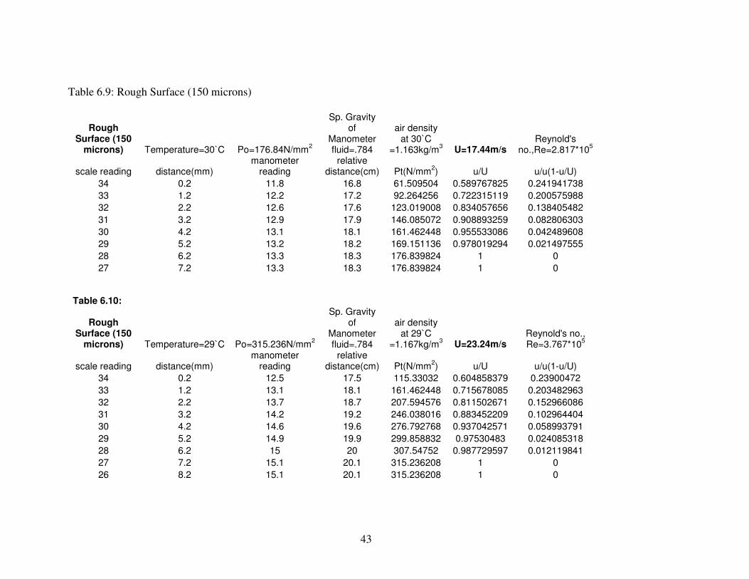
Table 6.9: Rough Surface (150 microns)
Rough Surface (150
microns) Temperature=30`C Po=176.84N/mm2
Sp. Gravity of
Manometer fluid=.784
air density at 30`C
=1.163kg/m3 U=17.44m/s
Reynold's no.,Re=2.817*10
5
scale reading distance(mm) manometer
reading relative
distance(cm) Pt(N/mm2) u/U u/u(1-u/U)
34 0.2 11.8 16.8 61.509504 0.589767825 0.241941738
33 1.2 12.2 17.2 92.264256 0.722315119 0.200575988
32 2.2 12.6 17.6 123.019008 0.834057656 0.138405482
31 3.2 12.9 17.9 146.085072 0.908893259 0.082806303
30 4.2 13.1 18.1 161.462448 0.955533086 0.042489608
29 5.2 13.2 18.2 169.151136 0.978019294 0.021497555
28 6.2 13.3 18.3 176.839824 1 0
27 7.2 13.3 18.3 176.839824 1 0 Table 6.10:
Rough Surface (150
microns) Temperature=29`C Po=315.236N/mm2
Sp. Gravity of
Manometer fluid=.784
air density at 29`C
=1.167kg/m3 U=23.24m/s
Reynold's no., Re=3.767*10
5
scale reading distance(mm) manometer
reading relative
distance(cm) Pt(N/mm2) u/U u/u(1-u/U)
34 0.2 12.5 17.5 115.33032 0.604858379 0.23900472
33 1.2 13.1 18.1 161.462448 0.715678085 0.203482963
32 2.2 13.7 18.7 207.594576 0.811502671 0.152966086
31 3.2 14.2 19.2 246.038016 0.883452209 0.102964404
30 4.2 14.6 19.6 276.792768 0.937042571 0.058993791
29 5.2 14.9 19.9 299.858832 0.97530483 0.024085318
28 6.2 15 20 307.54752 0.987729597 0.012119841
27 7.2 15.1 20.1 315.236208 1 0
26 8.2 15.1 20.1 315.236208 1 0

44
Fig.:-6.8

45
46
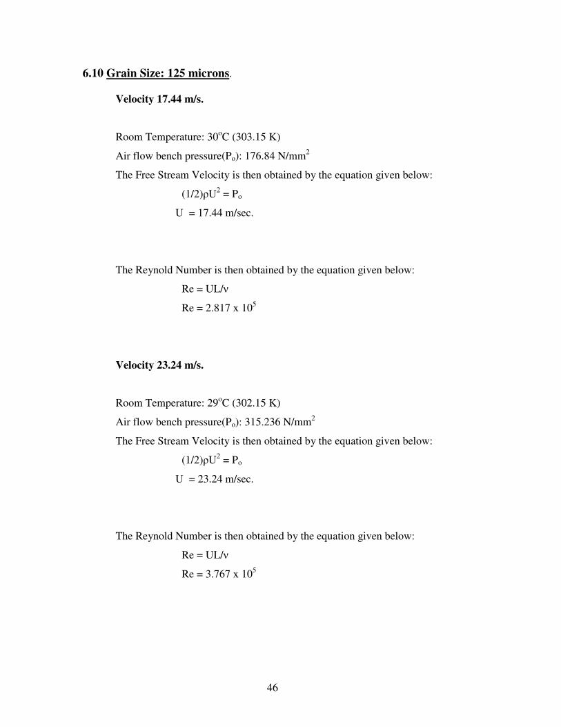
6.10 Grain Size: 125 microns.
Velocity 17.44 m/s.
Room Temperature: 30oC (303.15 K)
Air flow bench pressure(Po): 176.84 N/mm2
The Free Stream Velocity is then obtained by the equation given below:
(1/2)ρU2 = Po
U = 17.44 m/sec.
The Reynold Number is then obtained by the equation given below:
Re = UL/ν
Re = 2.817 x 10⁵
Velocity 23.24 m/s.
Room Temperature: 29oC (302.15 K)
Air flow bench pressure(Po): 315.236 N/mm2
The Free Stream Velocity is then obtained by the equation given below:
(1/2)ρU2 = Po
U = 23.24 m/sec.
The Reynold Number is then obtained by the equation given below:
Re = UL/ν
Re = 3.767 x 10⁵

47

48
Table 6.11: Rough Surface (125 microns)
Rough Surface (125
microns) Temperature=30`C Po=176.84N/mm2
Sp. Gravity of
Manometer fluid=.784
air density at 30`C
=1.163kg/m3 U=17.44m/s
Reynold's no.,
Re=2.817*105
scale reading distance(mm) manometer
reading relative
distance(cm) Pt(N/mm2) u/U u/u(1-u/U)
34 0.2 12 17 76.88688 0.659380473 0.224597865
33 1.2 12.3 17.3 99.952944 0.751809412 0.18659202
32 2.2 12.7 17.7 130.707696 0.859726954 0.120596519
31 3.2 12.9 17.9 146.085072 0.908893259 0.082806303
30 4.2 13.1 18.1 161.462448 0.955533086 0.042489608
29 5.2 13.2 18.2 169.151136 0.978019294 0.021497555
28 6.2 13.3 18.3 176.839824 1 0
27 7.2 13.3 18.3 176.839824 1 0 Table 6.12:
Rough Surface (125
microns) Temperature=29`C Po=315.236N/mm2
Sp. Gravity of
Manometer fluid=.784
air density at 29`C
=1.167kg/m3 U=23.24m/s
Reynold's no.,
Re=3.767*105
scale reading distance(mm) manometer
reading relative
distance(cm) Pt(N/mm2) u/U u/u(1-u/U)
34 0.2 12.5 17.5 115.33032 0.604858379 0.23900472
33 1.2 13.1 18.1 161.462448 0.715678085 0.203482963
32 2.2 13.6 18.6 199.905888 0.796333059 0.162186718
31 3.2 14.2 19.2 246.038016 0.883452209 0.102964404
30 4.2 14.6 19.6 276.792768 0.937042571 0.058993791
29 5.2 14.9 19.9 299.858832 0.97530483 0.024085318
28 6.2 15 20 307.54752 0.987729597 0.012119841
27 7.2 15.1 20.1 315.236208 1 0
26 8.2 15.1 20.1 315.236208 1 0
25 9.2 15.1 20.1 315.236208 1 0
49
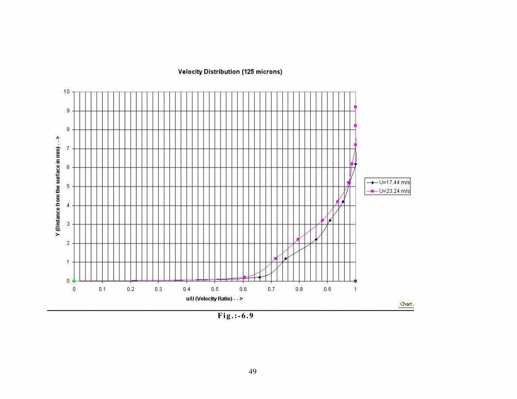
F ig . : -6 .9

50
V e lo c i t y Di s t r i but i on a t R ey no l d ’s Nu mb e r ( R e= 2 .8 x 105) f o r
d i f f e r en t Su rf ac e s
F i g . : - 6 . 10
V e lo c i t y D i s t r ibut i on a t R e yno ld ’ s N u mbe r ( Re =3 .75 x 105) f o r
d i f f e r en t Su rf ac e s
F ig . : -6 .1 1

51
6 .11 DISPLACEMENT THICKNESS AND SHEAR STRESS
OF SMOOTH SURFACE
From the graph of velocity U=17.53 m/s the equation formulated is :
u/U = -0.0061(y2/δ2
)+0.0879(y/δ)+0.682
Using this equation, the boundary layer thickness (δ) obtained is 0.4435 mm.
T h e sh e a r s t r e s s ob t a i n ed f r om t he fo rm ul a
τ o =µ (∂u /∂y) a t y= 0
= 0 . 08 79 Uµ /δ
= 0.0625 kg/m2
6 .12 DISPLACEMENT THICKNESS AND SHEAR STRESS
OF ROUGH SURFACE OF 300micron GRAIN SIZE
From the graph of velocity U=17.78 m/s the equation formulated is :
u/U = -0.0055(y2/δ2
)+0.1028(y/δ)+0.5207
Using this equation, the boundary layer thickness (δ) obtained is 1.3978 mm.
T h e sh e a r s t r e s s ob t a i n ed f r om t he fo rm ul a
τ o =µ (∂u /∂y) a t y= 0
= 1 . 10 28 Uµ /δ
= 0.2525 kg/m2

52
Table 6.13: BOUNDARY LAYER PARAMETERS CALCULATED ON
VARIOUS SURFACES
Type of Surface Boundary Layer
Thickness (mm)
Displacement
Thickness (mm)
Momentum
Thickness (mm)
Smooth Surface 0.4435 0.12243 0.0884
125 microns 0.4895 0.1511 0.102
150 microns 0.5240 0.1927 0.1554
180 microns 0.5918 0.2263 0.1986
250 microns 0.9824 0.4283 0.2806
300 microns 1.3978 0.6 0.342
53
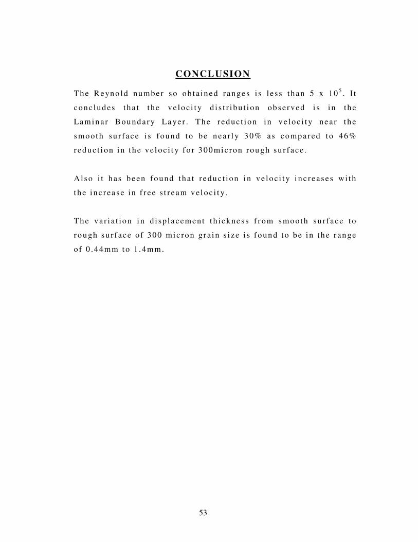
CONCLUSION
T h e R e yn o l d num be r s o ob t a in e d r a nge s i s l e s s t h an 5 x 10⁵. I t
c o n c l ud es t h a t t he v e lo c i t y d i s t r i bu t i on ob s e r v ed i s i n t h e
La m i n a r Bou nd a r y La ye r . T h e r e duc t i on in v e lo c i t y n e a r t h e
s mo o t h su r f ac e i s f o un d to b e n e a r l y 3 0% as co mp a r ed to 46 %
r e d u c t i on in t h e v e l o c i t y f o r 3 00 mi c ron ro u gh su r f a c e .
A l s o i t h as b e en fo u nd th a t r e du c t ion i n v e lo c i t y i n c r e a s e s wi t h
t h e i n c r ea s e i n f r e e s t r e am v e l o c i t y .
T h e v a r i a t i o n i n d i sp l a c em e n t t h i c kne s s f r om s mo oth su r f a c e t o
r o u gh s u r f a c e o f 300 mi c ro n g r a i n s i z e i s f o un d to b e i n t h e r a n ge
o f 0 .4 4mm t o 1 . 4mm .

54
RE FE RE N CES
1 . A f i r s t c ou rs e i n Ai r F lo w b y E . M a rk la n d .
T EC Q U IP M EN T Pub l i s h e r s Lt d .
1 M a r c h 19 76 .
2 . Bo u nd a r y La ye r T r a n s i t i o n e f f ec t ed by s u r f a c e ro u ghn ess an d
F r e e S t r e am Tu rb u l e n ce b y S . K. R ob e r t s a nd M . I . Y a r as .
J ou r n a l o f F lu i d E n gi n e er in g V o lum e 1 24 , I s s u e 3
M a y 2 0 05 .
3 . Fl u i d M ec h an ic s a nd F l u i d P o we r E n g in e e r i n g b y D r . D .S .
K u ma r .
K a t s on Pu b l i sh in g H o us e D e l h i .
1 9 99 .
W eb R e f e r e n c es :
ww w .s c i e n ce d i re c t . c om
ww w .w ik i p ed i a . c o m
ww w . en g in e e r i ng t o o l box . co m