Steel Design - College of Engineering - Lamar University Design - College of Engineering - Lamar...
46
-~ Introduction to Structural Steel DesiIDl . ". Steel is made out of98% iron, 0.15 to 1.7% carbon, and other elements such as silicone, manganese, and sulfur and phosphorous. If the percentage of the other elements mentioned is high then steel is known as alloy steel. The more carbon the steel contains, the more brittle it becomes with higher strength. Since ductility is the property we are most interested in, the percentage of carbon is usually under 0.5. Advantaees of Steel: - a) High strength per unit weight especiallywhen compared to concrete. This can reduce the size of the elements in the structure and increase the living space. b) Uniformity: that reduces the effect of time on stee~ as compared to concrete that changes through out its life. c) Elasticity: steel is elastic, that is it follows Hook's Law as long as its stresses do not exceed its yielding stress. d) Moment of inertia of steel is accurately calculated where as that of concrete changes as the cracks move up towards the neutral axis and past it. e) Permanence: the better the maintenance the longer is its life. With modem steel, it can be rolled to satisfy its purpose with little maintenance required. t) Ductility: since steel is a ductile material, it can undergo extensive deformations after which increased stresses are required for failure to occur. This is a property that can save _lives. , g) Fracture toughness: toughness is the ability of the material to absorb energy. Since steel has to be transported and then erected, it will be exposed to various types of sudden stresses (drilled, punched, hammered, banged around ...) that it should be able to absorb without large strength reduction. h) It is easier to add to a steel structure than it is to a concrete structure mainly due to connections. i) It is faster to build a steel structure than it is a concrete structure due to its lightness compared to concrete, it requires no curing time, and the members are easily connected (bolted, welded, and riveted). j) Recycled steel is a big part of the industry today" This allows the manufacturing of steel with 50 ksi yielding strength at a similar cost of producing the commonlyused 36 ksi. Disadvantaees of Steel: , . a) Maintenance cost: steel requires maintenance against corrosion. However this.cost1,9a;?- ; be eliminated by using atmospheric corrosion-resistant steels such as A242 and A588',r ;. ", , b) Fireproofing costs: steel will not ignite. However, at 1200°F steel has very little -,' ..~ strength. Its temperature should not exceed 800°F beyond which its strength is reduced . quickly.>.". c) Buckling: can occur when long slender steel members are exposed to compressive .,~~.:" loads. To avoid buckling, a larger cross-section is needed which will increase cost . .
Transcript of Steel Design - College of Engineering - Lamar University Design - College of Engineering - Lamar...

-~
Introduction to Structural Steel DesiIDl.".
Steel is made out of98% iron, 0.15 to 1.7% carbon, and other elements such as silicone,manganese, and sulfur and phosphorous. If the percentage of the other elementsmentioned is high then steel is known as alloy steel. The more carbon the steel contains,the more brittle it becomes with higher strength. Since ductility is the property we aremost interested in, the percentage of carbon is usually under 0.5.
Advantaees of Steel:
-
a) High strength per unit weight especiallywhen compared to concrete. This can reducethe size of the elements in the structure and increase the living space.b) Uniformity: that reduces the effect of time on stee~ as compared to concrete thatchanges through out its life.c) Elasticity: steel is elastic, that is it follows Hook's Law as long as its stresses do notexceed its yieldingstress.d) Moment of inertia of steel is accurately calculated where as that of concrete changes asthe cracks move up towards the neutral axis and past it.e) Permanence: the better the maintenancethe longer is its life. With modem steel, it canbe rolled to satisfy its purpose with little maintenance required.t) Ductility: since steel is a ductile material, it can undergo extensive deformations afterwhich increased stresses are required for failure to occur. This is a property that can save_lives.,g) Fracture toughness: toughness is the abilityof the material to absorb energy. Since steelhas to be transported and then erected, it will be exposed to various types of suddenstresses (drilled, punched, hammered, banged around ...)that it should be able to absorbwithout large strength reduction.h) It is easier to add to a steel structure than it is to a concrete structure mainlydue toconnections.
i) It is faster to build a steel structure than it is a concrete structure due to its lightnesscompared to concrete, it requires no curing time, and the members are easilyconnected(bolted, welded, and riveted).j) Recycled steel is a big part of the industry today" This allows the manufacturing of steelwith 50 ksi yieldingstrength at a similarcost of producing the commonlyused 36 ksi.
Disadvantaees of Steel:, .
a) Maintenance cost: steel requires maintenance against corrosion. However this.cost1,9a;?-;
be eliminatedby using atmospheric corrosion-resistant steels such as A242 and A588',r ;. ", ,
b) Fireproofing costs: steel will not ignite. However, at 1200°F steel has very little -,' ..~strength. Its temperature should not exceed 800°F beyond which its strength is reduced .quickly.>.".c) Buckling: can occur when long slender steel members are exposed to compressive .,~~.:"
loads. To avoid buckling, a larger cross-section is needed which will increase cost . .

d) Fatigue: is caused by a large number of repetitive tensile stress variations. This canreduce the strength and ductility of the steel causing a sudden failure..........
Steel Sections:
Besides having standardized shapes on the market, steel can be manufactured in any.desiredshapeandcross-section.The shapes or cross-sections with the highest moments of inertia are the most popular (1-beams, W sections, Tee shapes) because they can resist more bending stresses: cr=Mc/Ithe higher the 1the less the cr.The LRFD manuals provide all the standardized shapes with all their characteristics suchas dimensions,moments of inertia, radii f gyration, weight, .......The LRFD manual uses an abbreviation system for all the shapes, few examples are:
W27xl14 represents a W section with a depth of27 in and weight of1141b/ft
C10x30 represents a channel 10 in deep and weight of30 Ib/ft
Stress-Strain RelationshiDs for Steel:
-
jC/)
I t;I t\! I \'-
--- -- -:;- cL
..

Referring to the above figure:
1) From a to b the elongation increases constantly with stress and Hook's Law applies.2) The stress at point b is the final stress where Hook's Law applies (stress -strainrelationship is not constant beyond that point). It is calledthe Proportional Limit,Engineers refer to it as the Elastic Limit, and it is also known as the Proportional ElasticLimit. Stresses beyond that point will cause permanent deformations.3) Point c is the upper yield point (caused by rapid load application);point d is the loweryieldpoint (caused by slow load application). The yieldpoint is where the stress isconstant while elongation increases.4) The tangent to the curve at the yield point is a horizontal line.5) At point b the stress equals half the ultimate strength of steel.6) The shape of this curve can change with the type ofloading, temperature, and type ofsteel.
7) Brittle steel can fail suddenly without any yielding.Its stress vs. strain diagram will besimilar to that of concrete.
Modem Structural Steel:
With today's technology, the chemistry of steel can be altered to produce a variety oftypes of steel to fit almost every need. Refer to table 1-1 for the most common typesproduced.The binding force between the iron atoms is estimated to be over 4000 ksi. This is why wehave ultra high strength steels with yieldingstresses up to 300 ksi (not in the LRFD yet)and the industry is experimentingwith steels with up to 500 ksi yieldingstress. Since theyield stress can be increased without a major cost increase, high strength steel can be soonused due to the following advantages:a) High corrosion resistanceb) Light weight that reduces the cost of shipping and erection.c) Smallermembers will be required reducing the maintenance cost and increasing thelivingspace.
The Structural Desimer:
The first task a structural designer has, is to determine the loads the structure can beexposed to during its lifetime.Once the loads and their combinations are calculated, thedesigner has to find members that will sustain those loads. Whiledoing that, the followingpoints are to be taken into consideration:1) Safety: the erection of the structure itself have to be accomplishedin a safe way. Oncethat is done, the occupants should feel safe and hence should not see large cracks,deflections or sway.2) Cost: low cost should be achieved without jeopardizing safety. Therefore, a low costhigh strength structure should be designed by using standard size members, simpleconnections, and low maintenance ......

3) Practicality: will develop with experience. The more the designer is involvedwith thefabrication process, labor, erection, transportation, equipment used, the more practical,safe and cost efficientwill his design be.
Desien of Steel Members:
Designing is not just findingthe lightest member that can support the specified load. Thedesigner should consider the following while choosing his members:1) Pick members that are rolled and are availablein the market.2) Use the same members within the same floor although lighter members may work.3) Can the desired member be transported from the mill to the construction site?4) Pick members that can accommodate the rest of the structure (pipes, electric, plumbing,AC systems)5) Although it may cost a little more, nowadays-exposed structures a:repreferred to lookgood.
Calculation Accuracv:
The experience of the designer is what brings him to accurate calculations as humanelypossible. However, the design starts by assuming the possible loads, then the analysismethod is based on true assumptions and finallythe strength of the materialused can vary.Therefore, we can not claim design to be an accurate science, and that is why safetyfactors are needed.
Chapter 2
--Specifications. Loads and Methods of Design
Specifications and Building Codes: are good guides to the designer, they securestructural safety, and protect the public. Municipalities and state governments develop thecodes that engineers have to go by while designing. Most government agencies get theircodes from organizations that develop specifications for guiding the designer. AISC andAASHTO are 2 examples.
Loads: To be able to design a safe, efficient and economical structure, we have to have anaccurate idea of the types of loads the structure will be exposed to during its life time, andwhat combinations of these loads can occur at the same time.
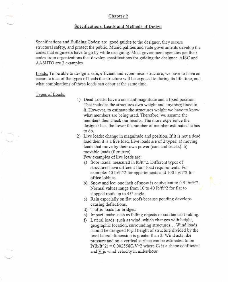
TyPes of Loads:l) Dead Loads: have a constant magnitude and a fixed position.
That includes the structures own weight and anyt:hiRg'fixed toit. However, to estimate the structures weight we have to mowwhat members are being used. Therefore, we assume themembers then check our results. The more experience thedesigner has, the lower the number of member estimates he hasto do.
2) Live loads: change in magnitude and position. If it is not a deadload then it is a live load. Live loads are of2 types: a) movingloads that move by their own power (cars and trucks). b)movable loads (furniture).Few examples of live loads are:a) floor loads: measured in Ib/ft;t'2.Different types of
structures have different floor load requirements. Forexample: 40 Ib/ftl\2 for appartements and 100 Ib/ftl\2 foroffice lobbies.
b) Snow and ice: one inch of snow is equivalent to 0.5 Ib/ftI\2.Normal values range from lO to 40 Ib/ftl\2for flat toslopped roofs up to 45° angle.
c) Rain especially on flat roofs because ponding developscausing deflections.
d) Traffic loads for bridges.e) Impact loads: such as falling objects or sudden car braking.£) Lateral loads: such as wind, which changes with height,
geographic location, surrounding structures. .. Wind loadsshould be designed foyif height of structure divided by theleast lateral dimension is greater than 2. Wind acts likepressure and on a vertical surface can be estimated to beP(lb/ftI\2) = 0.002558CsV1\2 where Cs is a shape coefficientand V is wind velocity in miles/hour.

- Earthquakes are another example of impact loads. Theycreate seismic forces. This horizontal acceleration of thegrotUldneeds to be considered in design. The effect ofearthquakes on buildings depends on the mass distributionof the buildings above the level being considered, and theability of the soil to withstand the lateral motion.
g) longitudinal loads: such as sudden stopping of trains ortrucks on bridges.
h) Other live loads: soil pressure on walls or foundations,water on dams, explosions, thermal forces due totemperature changes.. ..
Selection of Design Loads: besides all the specifications and building codes available, anengineers experience and insight in the future helps him select design loads accurately.
Elastic Design: or allowable stress design or working stress design. In these cases theloads are estimated and the members designed according to their allowable stresses (afraction of the minimum yield stress of steel). Method described in appendix A.
Plastic design: method estimates the loads and multiply them by a safety factor andmembers are designed based on collapse strength. Therefore the steel is used to itsmaximum limit making the approach more economical.
Load and Resistance Factor Design (LRFD): method is based on a limit state philosophy.Limit state: a structure or a part of the structure does not do its function. It is devided intotwo categories: 1) Strength limit state based on the structures load carrying capacity,buckling strength, plastic strength, fatigue and fracture. 2) Serviceability limit state basedon how the structure act tUldernormal loads, such as deflections, cracking, vibrations,and slipping.
In the LRFD method the working or service loads are multiplied by a safety factor,usually greater than 1, and the structure is designed to have an ultimate strength sufficientto support the factored load.
Ultimate strength = nominal strength or theoretical strength x 0Where 0 is less than one to account for possible tUlcertaintiesin design ormaterials.
Load Factors: increase the values of the loads to accotUltfor tUlcertainties.Since deadloads are estimated more accurately than live loads, their factors are smaller than those oflive loads. The LRFD manual provides many load formulas for various loadcombinations. For example: the usual load combinations used are given by equationsA4-1 and A4-2.
'-Resistance Factors: account for uncertainties in materials strength, dimensions andworkmanship in detennining the ultimate strength of the structure. Therefore thetheoretical ultimate strength (nominal strength) is multiplied by 0 « 1).for columns 0 = 0.85 for tension members 0 = 0.75 or 0.9
for bending or shear in beams 0 = 0.9Refer to table 2-2 page 57.
By using high load factors and small resistant factors we are protecting our design andthe public from uncertainties that can occur due to material strength, method of analysis,forces of nature, stresses during construction and the production of the material, and theaccuracy of the designed live load.
Reliabilitv and the LRFD S?ecifications: Reliability is the estimated percent of times thatthe strength of the structure will equal or exceed the maximum loading applied to thatstructure over its life time. Most LRFD designs give 99.7 % reliable structures. Thatmeans 0.3 % of the tinles the structure will be overloaded and is pushed to its plasticlimits or even to the strain hardening causing serious damage.

CHAPTER 3
ANALYSIS OF TENSION MEMBERS
Designing tension members is simple since they do not buckle. Knowing the load applied,and the stress limit of the material,'we calculate the required area. Then fi'omthe LRFDmanual we find a section that has at least that area. However, the LRFD offers a variety of
sections such as aogles ~' Wor S sections .I ' Structural t~,
or even built up sections fi'om several single sections such as - - - -;,- ~:,or J ['~ -.-J:-- ----
The dotted lines are tie plates or tie bars that connect the members together 'givingthem
stjffu~ss.If the connecting plates arePier~oratc;d~latesthen they are considered as loadcarrymgmembers. t~ J~7)
Desim Strensrth of Tension Members: a) Members with no holes drilled in them:
cr = F/A where cr= stress A = cross-sectional area of memberF = loadcarriedbythe member .
If steel is ductile, F > A x cryieldingdue to strain hardening. However, if the member isloaded to strain hardening, it will show a large increase in length and becomes useless andit can even fail causing the structure to fail.
b) If the member is connected by bolts and has bolt holes in it: in this case failurecanoccur in one of two ways: 1) Fracture failure at the net section through the holes. Theload causing this failure can be less than the load required to yield the gross section awayfi'omthe holes. 2) Yielding failure of the whole gross section.Therefore, the design strength in this case is the smaller off:
I) Limit state of yielding in the gross section:Pn =FyAg
and
Pu = ~tFyAg where ~t = 0.9ll) Fracture in net section where holes are present:
Pn = FuAeand
Pu = ~tFuAe where ~t = 0.75
--

'Where Fu=specifiedminimumtensilestress
~ ~ & = effectivenet area that can be assumedto resist tension at section withne., holes in it.
Table 1-1 in LRFD manual provides values for Fuand Fy
Net Areas: Placing a hole in steel reduces the area of steel that carries loads in tension orcompression, and hence increases the stress and their concentrations around the holes.However, if loaded beyond its yield stress, at its ultimate load we can assume the stress isuniformlydistributed over the net area unless members will be exposed to fatigue loadings.
Net Area = GrossArea - Area of Holes, Notches or Indentations'Where Area of Holes =Hole Diameter x Steel Thicknessand Hole Diameter = Bolt Diameter + 118"
Note: Punched area is 1/8" larger than the bolt diameter.
Effect of Stae:e:eredHoles: S~ggering holes can increase the net area and henceincreasing Pnand Pu.Ifholes are staggeredevery one of them and
~~I '."
d~ ~.~~~I~ c~ ofstaggering:
The Net Area
we can have different net areas. We findthen the smallest one controls.
- =[ gross width of the member -diameter of allholes along the considered line+ s1\2/4g] x thickness of plate.
If the cross-section has different thicknesses then:
The Net Area=
grossareaof the member-diameter of holes x thickness + sl\2/4g x thickness
Effective Net Areas: ifa member's cross-section is made of more than one member
(built-up section), then the forces are not transferred uniformly across its cross-section.Hence, the stresses at the connections and along a certain length of the member is higherand hence the cross-section will failbefore the steel reaches its failure tensile stress. Theuneven high stresses will extend ftom the connections to a certain length of the member,this is the transition region, before stresses are equallydistributed again. The stresses inthe transition region can exceed Fy,also shear lag can occur causing damage unless theload is reduced.
EffectiveNet Area =& = AU whereA = grossarea t\...~ d~.U =reduction factor to account for unequal
stress distn'butions

-
-
Note: the smaller x the larger the value of A.e
I
I
-:x.
Note: for bolted members A =net area of memberU = I - XIL~ 0.9 where x comes from manual
L =connection length (Length of line with maximumnumber of bolts)Table 3-2 page 80 gives differentvalues ofD for differentbolted conditions of differentsections.
U.Note: for welded members Ae = AUwhereA and. willhavedifferentvaluesaccordingtothe situations given on page 80 of the book.
Connectin£ Elements for Tension Members: such as splices or gusset plates. Thestrength of these connections is:a) For yielding of welded or bolted connections: Rn = AgFy and ~=0.9b) For fracture of bolted connections: Rn=AnFu and ~=0.75
Where An ~ 0.85Fyand An ~ 85%Ag
Block Shear: can also control the design strength. Block shear can create a tearing or
rupture failure and not a yielding situation. .s.~~
The block shear rupture design strength is:1) IfFuAnt~ 0.6FuAnvwe will have shear yieldingand tension fracture.Therefore, ~Rn= ~[0.6FyAgv+ FuAnt]
2) IfO.6FuAnv> FuAntwe will have tension yieldingand shear fracture.Therefore, ~Rn= ~[0.6FQAnv+ FyAgt]
,...
For both cases: ~ = 0.75Agv= gross area subject to shearAgt = gross area subject to tensionAnv = net area subject to shearAnt = net area subject to tension

CHAPTER 4
DESIGN OF TENSION MEMBERS
Selection of Members: we have a given tension load, we need to find a member tosupport it. The member found should have: a) Compactness to give the member stiffuess,b) Fit in its place in the structure and with other parts of the structure, c) Should beconnected properly to the structure to prevent Shear Lag.The type of connection we choose to use, will effect the type of section selected. Angles,W-sections and S-sections can be easilybolted, whereas plates, channels, and Tees are
welded easier. t* SlendernessRatio - Unsupported length! Least Radius of Gyration. ~LThe specificationsgive maximumallowable slendernessratios to prevent vibrations andlateral deflections and to ensure stiffuess. Tension members may even be exposed tobuckling during shippingor earthquakes and hence the slendernessratio is specified toprevent that by giving the tension member some compressive strength.
-For tension members:For members other than rods max S.R. = 300The designers experience will decide what S.R. to use for rods because their radii ofgyration is too smalland hence their S.R. is usually too large (greater than 300)For compression members:Maximum S.R. = 200
DESIGN: Ifthe tensile load Pu is given, we need to find the area of the cross-section. Inthis case we will have 2 areas to check for Ag (gross area) and Ae(effective area):
Min Ag = PuI~tFy and Min Ae = PuI~tFubut for bolted members Ae= AnU Therefore
ThereforeMinAn=PuI~tFuU
Min An= Min AelU
Therefore the Ag for the 2nd formula should be: Min Ag= Min An+ Estimated hole area(Estimated because we do not know the member yet and hence we do not know itsthickness)
Therefore Min Ag= PuI~tFuU + Estimated hole area
Also rmin= L/300 which will not let the slendernessratio exceed 300
Finallythe largest Agcontrols.
Steo bv steo orocedure:1) Find the value ofPu using formulas for the different types ofloading.2) Find Min Ag= PuI~tFy.

3)Using table 3-2 assume a value for U, and select a desired section that has a Min Ag thatis close to the one found in step 2.4) Find Min Ag= PuI~tFuU + Estimated hole area(use the thickness of the member selected in step 3)5) Find r = Min L/3006) Use the largest Ag from the 2 calculated above, and r and find a section from themanual.7) Check the section by doing the analysis like we did in chapter 3.
Briefly: Calculate Pu = ~tFyAg and Pu = ~tFuAe and they should both be greaterthan the given Pu(from the given loads).
Built Uo Tension Members: Section D2 and 13.5 of the LRFD Manual gives specificrules to connect tension members. The book on page 107 gives a few of those rules.
Rods and Bars: When used they can be welded or threaded and used with nuts.For threaded rods AD = Pu / ~0.75Fu with ~= 0.75
and Pu > 10K except for lacing sag rods or girts.Girts: are horizontal beams used on sides of industrial buildingsto resist lateral bendingdue to wind.Sag rods: provide support to purIms parallel to the roof surface and vertical support forgirts along the walls.The ADof the rod is from the diameter of the outer extremity of the threads.Table 8-7 in the manual gives properties of the standard threaded rods.Threads reduce the area of the bars, this problem is fixed by "upsetting" the rods, that ismaking the threaded part larger than the actual rod. This allows us to use the entire cross-section of the rod in design calculations. However, upsetting is costly and hence it isusually avoided.
Pin Connected Members: Are not used a lot anymore because the pins in the holes wearout and the connection becomes loose. Example: Eye bar
Desien for Fati2Ue Loads: Frequent stress variations or even reverse stresses can causefatigue. For example if cranes or vibration causing machinery are used in the structure, weshould consider fatigue. If subjected to tension stresses or stress variations, the memberwill form cracks that will spread and cause the structure to fail before the actual strengthof the member is reached.Note: Steel designers still do not have a perfect idea about fatigue failuresalthoughnumerous tests have been conducted.
S (Maximumstress) vs. N(Number of cycles to failures in millions)curves are used toshow fatigue failuresand it varies with the grade of steel and temperature.

Since we have the endurance limit, The stress where the life seems to be infinite,we candesign members that will not faildue to fatigue by making sure that the stress they will beexposed to does not exceed the endurance limit.
When do we design for stress fatigue?If anticipated cycles> 20,000, a permisable stress range should be calculated. This is done
as follows:1) Determine the loading condition using table A-lO.1 of appendix K of the LRFDManual (We have several loading conditions.)2) Determine the type and location of material ITomfigure A-lO.1 of the appendix.3) Determine the stress category (A, B, C, D, E, or F) ITomtable A-lO.24) Determine the allowablestress range for the service load and stress category ITomtableA-lO.3
5) Find Pu according to the different conditions. For example, if exposed to reversaltension and then compression, find Pu for tension and then Pu for compression.6) Then find Agusing the formulasdiscussed at the beginningof the chapter.7) Check the design.

INTRODUCTION TO AXIALLY LOADEDCOMPRESSION MEMBERS
CHAPTER 5
Columns are an example of compression members that are widely used in construction.Columns are vertical members with a large length to thickness ratio. Short verticalmembers are also known as struts.
Types of failure for axially loaded columns:1) Flexural buckling ( Euler Buckling): members are subjected to flexure or bending
when they become unstable.2) Local buckling: a part or section of the column buckles before the rest of it does due
to its small thickness at some parts of its cross-section.3) Torsion buckling (chapter 6)
Bucklin!! can occur due to:1) Manufactory defects.2) Eccentric load application (not at center of column)3) Weak end connections.4) Column not erected straight.
A columns tendency to buckle is measured by its slenderness ratio =L/rminwhere L = length of columnand rmin0-":: least radius of
gyration
A perfect column will have homogeneous materials throughout its length, will be erectedperfectly straight, and loaded exactly at its center. However, because of the following aperfect column does not exist:1) Cross-sectional imperfections.2) Residual stresses.3) Holes punched for bolts.4) Erection stresses.5) Transverse loads.
Those imperfections in columns can cause serious problems. The most important of theseproblems is developing bending moments for the columns that are not erected straight.Therefore, the design should take into consideration the stresses due to bending as well asaxial loading (chapter 11).
Column spacing is important for economical purposes and planning.The space 4 columns enclose is called a bay.
crf'0 0
0 0(Jl
0 0 0 0

- When shallow spread footings are used, Bays with length/width = 1.25 to 1.75, and withareas of approximately 1000 ft"2 will usuallyconstitute an economical design.
Residual Stresses: are a result of:
1) Uneven cooling of shapes after hot rolling. Quick cooling resists further shorteningdevelopingresidual compressive stresses, whereas slow cooling causes more shorteningdevelopingresidual tensile stresses.2) Welding 3) CamberingResidual stresses can vary &om 10 to 20 ksi and are to be considered especiallyforcolumns with slenderness ratios of 40 to 120. Columns with residual stresses reach their
proportional limitat a stress equals to half of their yield stress and the stress versus strainrelation is not linear &omzero up to the yieldpoint.A column with residual stresses is like a column with reduced cross-sectional area.
Sections used for columns: depends on availability,type of connection, type of structure.(Refer to figure 5-2 for few examples). However, the best compression member has aconstant radius of gyration about its centroid.
Develooment of column formulas: In 1757 Leonhard Euler realized the importance ofbuckling in columns.1) For short columns failure stresses are close to yieldingstresses.2) For intermediatecolumns, tests showed that residual stresses usually control failure.3) For long columns the end support conditions control failure.
The Euler Formula: The buckling stress decreases as the length of the column increase.At a certain length, and at lengths longer than that certain length, the buckling stressequals the proportional limit stress and we get an elastic buckling stress.Euler found the load that causes this elastic buckling:
P = (TI"2)EI/(r"2)From this equation we can see that the strength of the steel does not effect P.
In terms of slendernessratio, the critical buckling stress will be:
cr= PIA = (TI"2)E/(L/r)"2 This value is expressed as Fein theLRFD manual
If the critical buckling stress is greater than the proportional limit stress, then the columnis not in its elastic buckling stage and Euler's Formula will not apply.
End restraints and effective lenlrths of columns: Euler's Formula gives best results ifthe end supports are considered and the effective lengths are used for L. The better theend restraints the better the load carrying capacity. The effective lengths are the distancebetween inflectionpoints (points of Zero moments).

Effective length = KL where L = original column lengthAndK =effective length factor depending onend restraint and resistance to lateralmovement.
Assumingno sidesway,no lateraljoint translation, and perfect end conditionsp~ ~ ~ .,... r~
,\\'.
I..f~~ ~ ~ ~ ~The smallerthe effective length, the less chance it will buckle, the more load it will carry.However, this perfection is practically impossible,and the values ofK used in design areshown in table 5-1 page 141. These design values given for K are for preliminarydesignsand will not work for continuous columns (chapter 7).
Stiffened and unstiffened elements: Unstiffenedelements have one ftee edge in thedirection of compression, whereas stiffened elements are supported on both ends.A part of a member can buckle before the buckling stress of the entire member is reached(ex: thin flange or web). To prevent this, the LRFD provides width to thickness ratiolimitsof the individualparts of a section. To do that members are classifiedas:1) Compact sections: are stocky, buckling does not occur before the yield stress isreached, width to thickness ratio is less than Ap(limitingwidth to thickness ratio)(Table 5-2).2) Noncompact sections: yield stress is reached in some but not all of its compressionelements before buckling, the width to thickness ratio is greater than Apbut less than Ar(table 5-2)3) Slender compression elements: where the width to thickness ratio does not satisfYtheconditions of table 5-2. However, the stress reduction is severe and it is not economical touse slender members.
Short. lone and intermediate columns: the strength of a column and the way it failshighlydepends on its effective length. As the effective length increase, the buckling stressdecreases.
1) Long columns: buckling stress is less than the proportional limit stress. Therefore,elastic buckling controls and Euler's Formula applies.2) Short columns: failure stress equals the yield stress. Therefore buckling does not occur.In actual design this does not exist.3) Intermediate columns: some fibers yield and some do not. This is inelasticbehavior, andfailure is by yieldingand buckling. To use Euler's Formula in this case we have to modifyit and account for residual stresses. Most columns fall in this range.

Column Formulas: determine critical buckling stresses Fcr. From the critical bucklingstress Fcr we can get:
Po = Nominal Strength = AgFcr
and Pu = Ultimate Strength = 0AgFcr where 0 = 0.85
Consideringresidual stresses and out of straightness:
For inelastic buckling: Fer= [(0.658)"(Ac)"2]Fyfor A.e~ 1.5
For elastic buckling: Fer= [0.877/AcI\2]Fyfor Ac> 1.5
Where A.e = (Fy/Fe)"O.5 and Fe= III\2E/(KL/r)"2
Therefore Ac= (KL/IIr)(Fy/E)"O.5
However instead of using formulas, the LRFD manual provides values for 0eFcrforvarious KL/r values (minimumr). Tables 3-36 and 3-50 of part 6 of the LRFD.Also we can use the column tables in part 2 of the LRFD where we calculate KyLyandfind Pufrom the tables.
Maximum slenderness ratio: for compression members KL/r < 200
Note:
Fe = III\2E/(KL/r)"2 gives the least Feto cause buckling. Therefore, KL/r shouldbe maximum and hence r should be minimum. ill most cases ryis the smallest and (KL/r)yis used. However if long columns are used and bracing is made laterally (perpendicular toweak axis) both (KL/r)xand (KL/r)yshould be calculated and the largest number is to beused in calculating Fe.

----
CHAPTER 6
DESIGN OFAXIALL Y LOADED COMPRESSION MEMBERS
Introduction: two methods are used in designing axially loaded compressionmembers:
Method 1:
A trial and error process is used to design columns, by using formulas, because wehave to know a column size to find ~cFcr.We can assume a design stress (0-=F/A), by assuming a KL/r value and going to thetables. Then divide the factored load by that assumed stress to find the arearequired. Use that area calculated to select a column and check its ability to carrythe load.
Assuming a KL/r value requires a lot of experience.*For columns between 10 to 15 feet KL/r =40 to 60*For longer columns KL/r is a little higher.*For larger Pu (750 to 1000k) we need a large column with larger r and hence
smaller KL/r.*For lightly loaded bracing members KL/r can be over a 100.
PROCEDURE:1) Find Pu2) Assume KL/r3) Find ~cFcrusing tables 3-36 and 3-504) Find required area = PuI~cFcr
5) Find a section6) Find KL/rminof chosen section7) Find ~cFcrfrom tables 3-36 and 3-508) Find ~cPn = ~cFcr x Area9) If ~cPn~ Pu then the section is good10) If ~cPn::;;Pu then try another section
Method 2:
Using the tables in section 3 of the LRFD manual eliminates the need for a trial anderror process. The tables directly gives the value of ~cPnfor different steel sectionsbased on the least radius of gyration (which is ry in most cases and hence makingKL/ry control the design). IfKL/rx controls then a different approach has to be usedfor design.

PROCEDURE:1)2)
Choose the KL value in the weaker direction.
Knowing Pu =~cPn,enter the tables from the left with KL andmove to the right until a ~cPnvalue is found close to what we have.
3) The section above that value of ~cPnis the desired section.
For braced columns: 1) We can use trial and error like before, however, the largestof (KL/r)x and (KL/r)y is to be used. Therefore, to simplifythe problem we can assume that K and the strength are thesame in both directions, then if Lxlrx=Ly/ry(all unbracedlengths are equal) and Lx=Ly(rxlry)so that Ly isequivalent to Lx
If Ly(rxlry)< Lx then LxcontrolsLy(rxlry)> Lx then Lycontrols
If the unbraced lengths are different:
1) Enter tables with KyLy and select a section2) Find rxlryof that shape3) Multiply rxlry by KyLy4) If (rxlry)KyLy> KxLxthen KyLycontrols and selected section is
good.5) If (rxlry)KyLy< KxLx then KxLx controls, then reenter tables with
KxLxI(rxlry) and find the final section.
Built-Up Columns With Components in Contact With Each Other: If 2 plates areplaced side by side without any connections, then they will act separately and eachplate will carry half of the load, and the moment of inertia will be twice that of oneplate, and both plates wiU defor\D: equal amounts. Also, the plates will slip over each .other. b J.lb"~ ~~~ E~~~
OJ ~ ~n ~oj ~ ~ ,~~~~~r J!J~r
~ ~ ~ t?,,-If the 2 plates are ~onnected enough to prevent slippage, fully connected along itslength, then the moment of inertia is that of the whole cross-section and is four timesbigger. Also, in this case the plates deform different amounts. In this case KL/r =1.732L where K = 1 and r = (IlA)"O.5.
If the plates are connected only at their ends, then K = 0.5andKL/r = 1.732LThe last 2 caseshave equal designstresses and can carry the same loads as long asthe connected one doesnot start separating.

EJ
. Design strength of built-up sections is found by using the LRFD equations onpage 2-22 with one exception: If the column does not act as a unit and wehave relative deformations in its different parts causing shear stresses at theconnections. In this case we will have to modify KL/r of that axis of buckling(section E-4 of the LRFD).Equation E4-1 accounts for shear deformations:a) For intermediate connectors with snug tight bolts:
(KL/r)m=[(KL/r)A2 + (a/ri)A2]AO.5DEquation E4-2 for intermediate connectors that are welded or have fullytensioned bolts as required for slip critical joints (more than snug tight):
(KL/r)m ={(KL/r)A2 + O.82[(a)A2/(1+ a)A2](a/rib)A2]AO.5"
where (KL/r)(Jisthe unmodified slenderness of the whole built-up sectionacting as a unit.
(KL/r)m is the modified slenderness of built-up membersa =Distance between connectors.ri =Minimum radius of gyration of individual components (in)rib =Radius of gyration of individual components relative to its centroidalaxis parallel to the members axis of buckling (in)h =Distance between centroids of individual components perpendicular tothe members axis of buckling (in)a =separation ratio =h/2rib

(Kl/r)m about axis where buckling can occur has to be found if shear canoccur at the connections, and it should be checked if it effects the designstrength of the member, if it does effect the design strength then the membersizes may have to be changed.
Built-Up Columns With Components Not in Contact With Each Other: Sincecomponents of members are not in contact, they have to be connected to
each other. [b - - ,-~~The connection can be made of: Refer to page 177 figure 6-9a) Continuous cover plates with perforated holes for access purposes. LRFDE-4 for specifications.b) End and intermediate tie plates plus lacings.b) Battens not covered by LRFD.
In all types of connections, the connections should keep the members parallelto each other, prevent individual component buckling, keep distancesbetween components fixed, and make built up section act as a unity.
Note:
. While lacing, the L/r of components between connections can not exceed thegoverning KL/r of the entire cross-section.
. Lacing is subjected to a shear force normal to the member and equal to notless than 2% Of~CPDof the member. /'?
. Singlelacing has slenderness ratio limited to 140 ~~. Double laciQ.ghas slenderness ratio limited to 200 <
. Lacings are designed using column formulas
. If the distance between connection lines is greater than 15 in, then use doublelacing. OtherwJse use single lacing.
Procedure:1) Find distance between connections and determine if single or
double lacing is needed.2) From the geometry of the figure assume the angle of lace and
determine its length (length oflace or brace)3) Find L/r oflace and check if it is less than L/r ofthe entire cross-
section
4) Find load on lace which is Vu=0.02 ~cPDof the member5) Find shear force on each plane of lacing (V012) I ~6) Find the force in the bar [cosa(V0I2)] ~7) Find properties of lace bar (moment of inertia, area, radius of
gyration) in terms of the thickness and width.
8) Design the bar: assume L/r =x and plug the values found in step 7into L/r, the only unknown is the thickness t, so calculate t.
9) Check by finding L/r using the t calculated in step 8, find <j>cFcrfrom tl\bles,find required area =(Force in bars from step 6)/ <j>cFcr,find required dimensions and end spacings.
Bucklin!!:can occur in thr~e different ways:1) Flexural buckling or Euler's buckling, this is the buckling we talked
about so far.2) Torsional buckling is very complex and is avoided by careful
arrangements of members, and by bracing to prevent lateral movementand twisting, and by providing sufficient end supports. (Tables for W, M,
IIIS, tube and pipe sections are based on flexural buckling. If torsionalbuckling is to be accounted for, boxed sections work best; also shortermembers will be more efficient.
3) Flexural Torsional buckling For singly symmetrical sections such as Teeor Double angle. This type of buckling can occur and control the design.For unequal leg single angle column, flexural-torsional buckling alwayscontrols. Column tables for these sections are due to buckling about theweaker of x, y axis and for flexural torsional buckling (Appendix D inbook has an example of such buckling).
-

- CHAPTER 7
DESIGN OFAXIALL Y LOADED COMPRESSION MEMBERSCONTINUED
,.
--
Further Discussion of Effective length: The K values discussed in chapter 5, maynot be similar to real life conditions (end restraint conditions), add are used forpreliminary designs and for columns that are braced against sidesway. This chapter coverK values for coltul1nsin frames, columns subjected to sidesway, and columns that arebraced.
Sidesway related to K values: Sidesway is a type of buckling, it occurs whereframes deflect laterally due to the presence of lateral loads or unsymmetrical verticalloads or at ends of columns that can move transversely when loaded until buckling occur.Sidesway can be prevented by bracing or by shear walls between columns.The LRFD specifications C2 states that K = 1 is to be used for columns in frames withsidesway unless a proof can be shown for using smaller values.The following discussion is the proof: this principle is based on the fact that K values of acolunm depend on the whole structure, which the colunm is a pal1 of.
Referring to figure 7-2 page 189: Part a) of the figure gives K values wheresidesway is prevented by bracing's or shearwalls.
Part b) of the figure give K values wheresidesway is wlinhibited, that is stiffnesscomes from the structure only.
To use those charts in finding K values, preliminary column and girder sizes are needed.
Procedure for finding K values using the charts offigure 7-2:1) Locate the 2joints of the colunm.2) For every joint calculate: GA = 2:(Ic!Le)/2:(Ig/Lg) and GB = 2:(IdLe)/2:(Ig/Lg)The letter "c" stands for columns, whereas the letter "g" stands for girders.Therefore we add up (IdLe) for every colwnn attached to that joint and divide that resultby the summation of (Ig/Lg)of every girder attached to that samejoint.3) Plug the values ofGA and GBin the charts of figure 7-2 andjoin them by a straight
line.
4) Read the K value at the intersection point between the straight line of step 3 and themiddle COIWllilof the chart.
Those aliglhnent charts are developed from a slope deflection analysis and the fact thatthe resistance to rotation provided by the beams and girders at one end of a columndepends on the rotational stiffness of those members.

Recommendation for using the alignment charts: For end suppolis1) TheoreticallyG = 00 for pin connectedcolunUls.However,a valueof 10is used
because fi-ictionoccurs.2) Theoretically G = 0 for rigid column supports. However, a value of 1 is used since
there is no perfectly fixed ends.3) For beams and girders rigidly attached to columns multiply their IlL by the factors of
table 7-1 page 192. ~ d
-
Stiffness Reduction Factors: the K values from alignment chalis are based on manyassumptions (elastic colunUlbehavior, all columns buckle simultaneously, members haveconstant cross-sections, all joints are rigid...), such assumptions make the K values veryconservative and hence needs to be corrected.In the elastic stage, colwnn stifthess is proportional to EI where E is the modulus ofelasticity (29,000 Ksi). In the inelastic stage, colunm stiffness is propOliional to ErIwhereEr is the reduced or tangent modulus (smaller than E). Therefore, for inelastic behavior,Er is used reducing G and hence reducing K.Therefore, if the alignment charts have to be used for inelastic behavior,The G value has to be multiplied by a reduction factor SRF where:
(SRF) =EriE== Fer inelasticl Fer elastic ==(PulA)I Fer elasticSRF values for different PulA values are in table 3-1 of the LRFD manual. If PulA issmaller than the tables, it is in the elastic range.For inelastic buckling the ptocedure is as follows:1) find Puand a trial COIUlllilsize.2) Find PulA and find SRF3) Find G elastic for the column and multiply them by SRF and use those values in the
alignment charts to find K.4) Find KL/r and ~eFer5) Find Pu= ~eFer x A6) Check Puof step 5, if it is greater than that of step 1 then colunm is good.7) If Puof step 5 is less than that of step 1, then try a different colunm size.
Columns Leaning on Each Other for In Plane Design: For wlbraced frames withbeams rigidly attached to the colwnns, we design each colunm individually usingsidesway uninhibited alignment charts. Those charts are based on the assumption that ifone column gets ready to buckle, all the colunms at that level will also be ready to buckleand hence they can not support each other. However, sometimes due to different loadingconditions the exterior colunms have more buckling strength than the interior columns,and when the interior colunms start to buckle the exterior ones will hold them.A pin-ended colunm does not support lateral stability and is called leaning colunm (itdepends on other parts of colwnn).
Base Plates For Concentricallv Loaded Columns: The base plates job is totransfer the compressive load on the colunms to a large area of the footing because thefootings (concrete or soil) compressive strength is usually smaller than that of the column(figure 7-11 page 202 gives types of connections).

Column base plates have to be properly positioned and leveled in place. This is done asfollows:a) For base plates of20 to 22 inches we use leveling plates (0.25 inches thick and same
size as the plate) that are set at right elevation where the column will be placed withits base plate on top of it.
b) For 36 inch base plates, leveling nuts on four anchor bolts are used to adjust the plateup or down.
c) For plates greater than 36 inches, the plates are placed in advance and leveled withshims and wedges, then the column is based on top of it (done that way because theyare too heavy).
To ensure complete load transfer from colunm to plate, Good contact ~etween themshould occur, Section M2.8 of the LRFD. .:JL'L,-
Approximately: Maxinnun moments in a base plateoccursat distancesequalto 0.8brand0.95dapart .
(figure 7-12). Find the bending moment at each of I'"'-- U I
these sections and the largest moment controls in 1~1
' Ifinding the area of the base plate. I I I I t 0 f. I
-4- ",-{,.'v. A:: r - <w.'i.()ctPlate Area: a) If plate covers entire area of concrete beneath ii, the design strength ofconcrete should at least be:
J
Pu = ~cPp = ~c(0.85t\)(AI)Where AI = Area of plate
fc = Compressive strength of concrete at 28 days~c= 0.6
Therefore, Al = Pu/~cO.85fc
b) If area of concrete is greater than area of base plate(concrete lmder plate is strongerbecause concrete outside the plate prevents it from movement). Therefore, designstrength of concrete is higher and this is accolmted for by multiplying~c(0.85fc)(AI) by (A2/AI)"0.5 that should be less than or equal to 2.A2 = total area of concrete.
Therefore ~cPp= ~c(O.85fc)(Al)(A2/AI)"O.5 where (A2/AI)"0.5 s:2
Therefore Al = PuI~c(O.85fc)(A2/AI)"0.5 where (A2/AI)"0.5may not be greater than 2
Note: Al should be ~ column depth x flange width = column dimensions.
Once AI. the controlling value, is found, the plate dimensions have to be optimized. Todo that the thickness of the plate is kept at a minimum if m = n of figure 7-12 and thisoccurs if the following equation is satisfied: B ==AI/N where N =(AI)"O.5 + 11
AI =areaof plate= BN and A= O.5(0.95d- 0.8br)

Plate Thickness: W.A. Thortons method.
The plate thickness is determined using I = max(m, n, or Ari)
Where t = 1(2PulO.9FyBNYO.5
IAnd An = A(dbfY'O.5/4 where A= 2(XYO.5/1 + (l-X)"'O.5 ~ 1
Where X = [4dbr/(d + bfY'2]xPul~cPp
Ifplate covers all the concrete then ~cPp = ~cO.85fcAIIf concretearea is greaterthanareaof platethen~pPp=~cfcAI(A2/AI)I\O.5
where (A2/Al)I\O.5 ~ 2
General Procedure for Analvsis:1) Find Al using the fot'l11ulathat applies to the given situation.2) Make sure it is at least as large as the column (dbf)3) Optimize base plate dimensions using N = (AI)"'O.5+ ~ and B = AI/N4) Find thickness (figure 7-12) m =(N - O.95d)/2
Where n = (B - O.85bf)/2And find Anias described before
Take the maximum value of step 4 and findt = 1(2Pu/O.9FyBN)I\O.5
\_n-\-O.80/J/-j-II-jtIII
I
O.95d
\
d N
//IL
\
CHAPTER 8
INTRODUCTION TO BEAMS
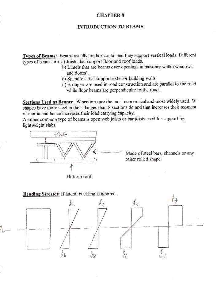
Tvpes of Beams: Beams usuallyare horizontal and they support vertical loads. Differenttypes of beams are: a) Joists that support floor and roofloads.
b) Lintels that are beams over openings in masqnry walls (windowsand doors).
c) Spandrels that support exterior building walls.d) Stringers are used in road construction and are parallel to the road
while floor beams are perpendicular to the road.
Sections Used as Beams: W sections are the most economical and most widelyused. W
shapes have more steel in their flanges than S sections do and that increases their momentof inertia and hence increases their load carrying capacity.Another common type of beams is open web joists or bar joists used for supportinglightweight slabs.
.." Made of steel bars, channels or anyother rolled shape
Bottom roof
Bendine Stresses: If lateral buckling is ignored.
~._ - I_ --- -- -
L.--
fa

Stress calculated from flexural formulas gives the stress fb< tY (beam is below elasticlimit)
fb= Mc/ITherefore fb= MIS
where IIc = Section Modulus = S = Constant
Until fyis reached, the stress increases linearly.The yield moment is the moment that produces fyin the outermost fiber ofthe section. Asthe moment increase past the yield moment, the outermost fiber yields and the fiber closestto the neutral axis has to resist the load. The higher the moment, the more fibersyieldsuntil all the fibers yield and a Plastic Hinge is formed (no extra moment can be resisted) atthe plastic moment (last figure in the above diagram).
MplasticIMyielding= Shape Factor\
Plastic Hin!!:es: For analysispurposes, we assume that the plastic hinge is concentratedon one section, however, it actually spreads out to other adjacent fibers as shown on thefigure below. If a beam is loaded to failure, the plastic hinge becomes visible.
Pu.. ~~~~~~~~1v~U-~Q~-~ ,
-
Elastic Desim: Elastic theory designs are based on the load that will first cause a stresssomewhere in the structure to equal the yield stress. However, due to extensive research,we know that a great deal of yieldinghas to occur before failure exists, therefore, theelastic theory is considered to be too safe.
For a rectangularsection,I = bdl\3/12 and c = d/2Therefore S = bdl\2/6
My = fy x bdl\2/6
The yield moment My= fy x Swhere S = Elastic Modulus = I/c
OIL
The Plastic Modulus:
and
Another method used to find Myis by calculating the moment created by the coupledeveloped from the tension and compression forces on the section.
My = Moment created by the couple
-

.J.'-/ -~JlA.
fl , ( /J ~ ~ T~ioxi_){ b =~ :~1r~< > J
H..t i\.. /..f
b dU ~::: #;.6 x-bJ, ': 14 bel
At full plasticity where every fiber has yielded:the PI~tic mome~ Mp,alsoknown as thenominalmoment Mn,can be found in the same way.
< 6 '> i~I r I I /10J.
'f
- --
_ _ _1=0--_11tr\ ~ (If :(1 J 'J b x~J- cL
11,.,. ~ t1 p::; J~ bol.2.
't
Or we can also find Mp= fyx Z where Z is the plastic modulusFor a rectangular section Z = bd"2/4
The shape factor = Mn/My = fyZ/fyS= Z/S
For a rectangular section the Shape factor = (bd"2/4)/(bd"2/6) = 1.5
Note: For unsymmetricalsections, the neutral axis of the elastic condition is not the sameas that for the plastic condition.
MI~~ _ * For the elastic condition, the neutral axis coincides with the neutral axis of the entire- ~ - section. .
NJL f?t * For the plastic condition the neutral axis is located such that the area above the neutral- -axis equalsthe areabelowthe neutralaxis.I
AI =A~The CollaDseMechanism:I) A staticallydeterminate beam will fail if One plastic hinge develops. The plastic hingeoccurs at the location of the maximummoment developed by the maximumload a beam
cansupportbeforefailure. .p__=~ U ~ ~ ~ ~r

2) A statically indeterminate structure requires at least 2 plastic hinges to fail. This numberof plastic hinges varies from structure to structure.
S ~ ~
td ~~~LT- S~r~H~
Virtual Work Method: used for plastic analysis of structures.
1) Load the structure to its nominal capacity Mn.2) As Mnis reached, we assume that a smalladditional displacementoccurs.3) The work performed by the external loads during this displacement is equatedto the internal work absorbed by the hinges.
Example:
L
3 plastic hinges will develop.
From geometry and symmetrydetermine the rotation angles at eachhinge. erad= tane = sine
The work performed by external distributed loads = load x average deflection ofmechanism
The work performed by external concentrated loads = load x actual deflectionunder load.
For our examplework = wnL x (eL/2)/2 = wnL x eL/4
Also, The internal work absorbed at the plastic hinges=
LMn at each plastic hinge x angle of rotation at that hinge
Foe our example, internal work absorbed at the plastic hinges = Mn(e + 2e + e)

Next we equate the work perfonned to the internal work absorbed by the plastic hinges.
wnL x 8L/4 = Mn(8 + 28 + 8)Therefore, Mn = wnL/\2/16or Wn= 16Mn/L /\2
Note: A system may require the drawing of several mechanismsto find which one willcontrol. The case that controls will have: Pnis smallest in terms ofMn
or Mnis greatest in terms ofPn
Location of Plastic Hin2es for Uniform Loadin2: when the beam is simplysupported orwhen the beam is continuous.
L
--
As the load increases, plastic hinge first forms at the fixed end, and then the moment willchange until another plastic hinge forms at a distance x from the right side.
Using the virtual work method (only includeplastic hinges):
Mn[8 + (8 + ({L-x}/x)e)] = wnL[8(L - x)]O.5
Next we solve for Mn,then find the first time derivativeofMn in terms of x (dMn/dx),thisvalue equals to the shear. However, at maximummoment the shear equals to zero.---'

Therefore by setting dMn/dx= 0 will be used to calculate x.
For our example x = 0.414L
Continuous Beams: are solved using the same approach as that used for single spans,however, each span is considered separately. Refer to examples.

CHAPTER 9
DESIGN OF BEAMS FOR MOMENTS
Introduction: When a beam is loaded, the section above the neutral axis will be incompression, and hence acts as a column such that as the bracing length increases, theresisting beam moment decreases. We have 3 zones of buckling.
Plasticbuckling-fullplastic moment(Zone I)
Elastic
buckling(Zone 3)
,
J
'o,-
.
.
f.
.?O::
.",::.
Lp L,
- Lb(laterallyunbracedlengthof compressionflange)
a) Zone 1: Plastic Buckling: When we have contin~ous lateral bracing of thecompression flange. Most beams fall in this zone.If the spacing or the lateral unbraced length ::;;Lp then weare in Zone 1 (Lpdepends on beams cross-section and Fy)
Therefore, the beam can be loaded until Mp (plastic moment) is reached and it also can beloaded past that where moments redistribution occurs because the lateral bracing preventsthe rotation of the beam allowing it to carry more load. (Chapter 8 where all fibersreaches Fy) .
-~
b) Zone 2: Inelastic Buckling: bracing at short intervals: We can load the member untilsome and not all its fibers reaches Fy(no full moment redistribution).This inelastic range ends when Fy is reached at only one point or location on thebeam. This controls the maximum unbraced length we can have and still be in theinelastic range. This length equals Lr (Lrdepends on the cross-section, Fyand residualstresses).Therefore, at an unbraced length Lr, as soon as an Fy is created at any location,buckling occurs. However, usually buckling occurs before Fy is reached due toresidual stresses.
c) Zone 3: Elastic Buckling: braced at large intervals. L > Lrb
t.,
tfI
t
I,
r
tt-
,
t
tr./

In this case buckling occurs before Fyis reached anywhere. As the moment increases,Meris the moment that causes the section to twist and the compression flange to movelaterally (discussed later in the chapter).
Plastic Bucklin!!: Zone 1: for compact I or C shaped sections.
If Lb~ Lp(for elastic analysis) where Lb = unbraced lengthAnd Lp = 300ry/(FyfY'0.5
And if
Lb~ Lpd(if plastic analysis is used) where Fyf is the specifiedminimum yield stress in theflange, ksi
where Lpd= [3600+ 2200(MIIM2)]ry/Fy
Then
Mn = Mp = FyZ ~ 1.5MyAnd
Mu = ~bMn = 0.9 FyZ
In the above equations, MI is the smallest moment at the end of the unbraced length, and
M2 is the largest moment. MIIM2is positive for double curvature bending ~Andit is negativefor singlecurvaturebending.~ ""Also, the equations apply for Fy~ 65 ksi.The value of Mp is limited to a maximum of I.5My to limit the large deformations thatcan occur when the shape factor is larger than 1.5.Note: The plastic moment in Zone 1 is not effected by residual stresses because thecompressive residual stresses equals the tensile residual stresses and hence cancel theireffects.
Desi!!n of Beams: Zone l:To design beams some of the considerations should be: 1)moments 2) Shears3) Deflections 4) Lateral bracing of compression flanges 5) Fatigue
Step 1 in design is to select a beam that has enough moment capacity to carry (~bMn),thefactored moment that needs to be carried.Step 2 is to check all the other criteria to see if they have any effect. The manual startingat page 4-15 gives different sections to be used for different Zxplastic moduli.
To select a shape we should: 1) Select the lightest member since it is bought by the lb.2) Zx on page 4-15 of the manual are for the horizontal axisfor beams in their upright position. If the section is turnedon its side, its Z is found in the property tables.

Beam weight estimates: A student can not estimate a weight by just guessing.1) Calculate the maximum bending moment without the
beam weight.2) Use that moment In the tables and pick a section.3) Use the weight of that section or a little more as your
estimated beam weight.
Note: IfLb = 0 then we have full lateral support for compression flange. Then we will:1) Assume or estimate beam weight2) Find Mu according to type of loading3) Find Zx = MulO.9Fyand go to tables in section 4 of the
LRFD manual and find the cross-section required.
Holes in Beams: need to be avoided if possible. If it is not possible to avoid them then:1) Place the holes in the web if shear is small (holes in
web reduces shear strength)2) Place the holes in the flange if the moment is small
Theoretically bolt holes will shift the neutral axis from its position. However, tests do notshow any considerable effects to be considered, and failure in steel beams depends on thestrength of the compression flange.Flexural test shows that although holes are present in the tension flange, failure occurs inthe compression flange. Also, bolt holes in the web will not reduce the value of Z enoughto make a difference.Beam strength with no holes and that of beams with holes in them that do not exceed15% of the gross area of either flange is almost the same. Therefore, strength of no holesequals strength of 15% holes.LRFD specifications: Do not subtract area of holes if it is 15% or less than the area ofeither flange. If the area is > 15% only subtract what exceeds the 15%.Most practices are more conservative and do subtract the area, even if holes are in oneflange they subtract holes like if they are in both flanges.
Lateral Support of Beams: Most beams have their compression flanges restraintlaterally against buckling. For example it can be restrained by the concrete slab that itsupports on top of it. That makes the beam fall into Zone 1. If it is not laterally supportedit reacts like a column in terms of buckling, and this buckling can be effected by residualstresses, spacing of lateral supports, type of supports or restraints, type of materials, andtype of loading. The tensile flange prevents buckling until the bending moment increasesenough to let the compression flange buckle. Once buckling starts torsion occurs, and thesmaller the torsional strength of the section (Wand S shapes do not have high torsionalstrength) the faster it fails.Built-up boxed shapes resist torsion perfectly.
Inelastic bucklin2: Zone 2:1) Compression flange is supported laterally at intervals.

- 2) Member is bent until the yield strain is reached in some but not all of itscompression elements before lateral buckling occur.
3) Bracing is not enough to permit the beam to reach full plastic straindistribution before buckling occurs.
4)Due to residual stresses yielding will begin in a section at applied stresses equalto: Fyw-Fr where Fywis the web yield stress
andFr is the compressive residual stress = 10 ksi forrolled shapes and 16.5 ksi for welded shapes
5)If Lb (for I or C sections) > Lp and less than Lr then we will have inelasticfailure
If Lb> Lrthen we will have elastic failure before Fyis reached (Zone 3)6)Bending coefficients used in formulas:
Cb is used to account for the effect of end restraints and types of loading onthe lateral buckling.
Cb = moment coefficient = 1.75 + 1.05(MIIM2) + 0.3(MIIM2Y'2 ::; 2.3
..
M2 > Ml and they are the bending moments at the ends of the unbraced lengthabout the strong axis of the member.If the moment within the unbraced length is > Ml or M2then Cb= 1Part 6 of the LRFD manual gives values ofCb for different MIIM2values.
tJ Note: The equations of Zone 2 and Zone 3 where developed based on Cb= 1.
However, the LRFD provides Cb > 1 to multiply Mn with, hence increasingthe moment capacity because Cb= 1 is for single curvature and in most cases
we have double curvature. I.:>~ L.' ~ ~
~/-~~--- ~/~ ,.-t £t;~~:::tHence, by increasing the moment capacity we reduce cost. However, CbMnmay not be > than Mp= FyZof Zone 1Equation FI-3 page 258 can be used to calculate Cb
Moment Capacity of Zone 2: as the unbraced length of the compressionflange increases beyond LJf,the moment capacity decreases and decmasesuntil Lr (unbraced length) is reached and elastic buckling occurs as Fy isreached.
For I or C shapedsections: If Lb=Lrthen Mu=~bMr=~sSx(Fyw-Fr)Lr is a function of several properties of the beam such as cross-sections,modulus of elasticity, yield stress, torsional strength. ..
For the unbraced length between Lpand Lr : and for Cb= 1
~bMn= Cb[~bMp-BF(Lb -Lp)]::; ~bMpBf is a factor found in the LRFD for every section.

- Procedure: for determining the moment capacity of a beam whose Lp< Lb< Lr1) Find Lp,Lr, ~bMn,~bMp,and BF from table 4-15 in the LRFD manual2) Compare Lbgiven to Lpand Lr.
If Lp< Lb< Lr then we have inelastic buckling.3) ~bMn= Cb[~bMp -BF(Lb-Lp)]
Elastic Bucklin!!: Zone 3: IfLb > Lrthen elastic buckling will occur before Fyis reachedanywhere. The beam supports the moment by bending aboutits stronger axis until Meris reached where the beam buckleslaterally about its weaker axis. As it bends laterally, the partin tension tries to keep the beam straight causing the beam totwist and buckle laterally. (figure 9-10).
The flexural torsional buckling occurs at :
Mer = Cb(n/Lb)[EIyGJ + (nE/Lb)"2(lyCw)]"0.5
-Where G = Shear modulus of elasticity of steel = 11,200 ksi
J = Torsional constant in (inches)"4 in manual tables partlCw= Warping constant in (inches)"6 in manual tables
This equation applies for channels and I shapes whereas othersections have different formulas in F1.4 and F1.5
Procedure: for computing Mu= ~bMerfor a certain section with a certain Lb
1) Check ifLb > Lr Lr is found in the load factor design tables2) From the manual get Iy,J, and Cw4) Use the appropriate formulas.5) Or we can use part 3 of the LRFD manual where curves are plotted for
~bMerand ~bMnon Page 4-113.Those charts do not consider factors such as shear, fatigue, anddeflection. . .
6) Or we can use:
-
n CIL ~ C to Sx Xl nLh/r-d

--Design Of Beams
Miscellaneous Topics
Desim Of Continuous Beams:a) Plastic Analysisfor sections with Fy~ 65 ksi. This method includes the redistribution ofmoments caused by overloads if the continuous beam is braced enough laterallyon itscompression flange.b) Elastic Analysisthat actually estimates the real plastic behavior by taking the designmoment equal to the largest of:
(Largest negative moment)xO.9or
(Largest positive moment) + O.1x(the average of the two negative11.t1\.(1~ moments under the largest
positive moment)
(]) @Note: If the moment diagram only has positive moment then the design moment is themaximumpositive moment.
Plastic Analvsis:Procedure:a) Dothe plasticanalysis (.~~Jb) FindMufor everyspanc) Choosethe largestMud) Find Zrequired= MulO.9Fy
e) Go to tables and find the section
Elastic Analvsis: Procedure: a) Draw the moment diagramb) Find Muusing the formulas given abovec) Find Zrequired= MulO.9Fy
d) Go to tables and find the section
Shear: As a beam is loaded the different layers of fibers tend to slip of each other.
CI -, ,- .!
, - -. ---T- - - - - - ~ J ~
* Horizontal and vertical shear at the same point are the same and one can not occurwithout the other.* In steel, usually shear is not a problem because the web of rolled steel can resist largeshearing forces.* Extensive shear forces occur in steel where:
i) Rigidlyconnected members (columns and beams) whose webs are in the sameplane.

ii) Where a beam is notched.
ill) Large concentrated loads are placed at short distances &om supports.i .
'
rIIDj' A !.
l~ ~..
fL t Therefore, the shear isi (0) basicallysupported by the web.
As the moment increases, the members will start yielding, and hence part of the web startsyieldingreducing its shear carrying capacity. Therefore, we use a reduced shear value andassume it is carried by the entire web are~ where area of web =Aw= d x tw
Shear strenlrth Exvressions:
a) Web yielding:includes almost all rolled beam sec,jons.Ifhltw ~ 418/(Fyw)"O.5 wher~(Fyw)A0.5 = 70 for 36 ksi
'1fV(Fyw)AO.5= 59 for 50 ksiFywis the specifiedminimumyieldingstress of the webthen V0 =0.6FywAw
And
Vu = ~uVo where ~u = 0.9
h = clear distance between fillet.
* For built-up sections that are welded h is the distance between the flanges.* For built-up sections that are bolted h is the distance between the bolt lines in the web.
~-_ ~-_1 KI I
b) Inelastic buckling ofthe web:If 418/(Fyw)"O.5< hItw~ 523/(Fyw)A0.5Where 523/(Fyw)"O.5= 87for Fy= 36 ksi
)!r .523/(Fyw)"O.5 = ~ for Fy = 50 kSl
Then Vo = 0.6FYWAw(418/(Fyw)A0.51h1tw)And
Vu=~vVo where~v= 0.9
c) Elastic buckling of the web:
If 523/(Fyw)"O.5< hI~:5;260Then Vn= (132,000Aw)/(hItw~ Vu= ~vVn where ~v = 0.9

Note: The LRFD manual in section 4 titled "Beam W shapes maximumfactored uniformloads in Kips for beams laterally supported" gives values for ~vVnand other informationon web yielding.One way to increase the shear strength ofthe web, is to bolt plates on both ofits sides.
Deflections: in steel beams have to be limited due to:i) Large deflections can effect other parts of the structure attached to thebeam.
ii) Bad appearance and unsafe looks.Service live load deflections are limitedto 1/360 ofthe span length (that limitpreventscracks in underlyingplaster). This value can change with different types ofloads,structures and specifications.The deflection limitsare decided by the designer'sexpenence.Deflection can also be limited by limitingthe depth span ratios (Table4-2 in LRFD).Camberingcan help reduce deflection but it is expensive.To determine the deflections:
~ = MLI\2/CIIx
~-L ~~where M is the moment based on the
uniformlydistributed service loadsCl is a constant figure 10-8Ixis moment of inertia about x-axis
If deflection controls the design of a beam:i) Assume a beam weightii) Find Wuand Muiii) Find Zrequirediv) Find a section from the tablesv) Find the actual deflection of the sectionvi) If the actual deflection is greater than the required deflection, Calculatethe maximumallowedIx=(actualdeflection/requireddeflection)(Ixof selectedmember)thatwilllimit the deflection.vii) Use the calculated Ixin part 4 of the LRFD "Moment of inertiaselection tables" and find a section for the Ixcalculated in step vi.
Vibrations: and their control is a very important part of the design.Damping of vibrations can be controlled by: stiffer structures, partitioning, officefurniture...Ponding: occur when water is not drained as fast as it is pored, this creats deflectionsthatcan cause failures.To prevent ponding roofs have to be inclineda minimumofa quarter ofan inch per foot, and to prevent failure the roof should be stiff enough.
....

Unsymmetrical BendiDl!:occurs about an axis other than the principle axis.11~1C
If the load is not perpendicular to the principleaxis,it is broken into its components about the principleaxis and the moment it produces about the principleaxis (Mux and Muy)
y.1To check the ahequacy of a member when it is exposed to bending about both axis and totension or compression:
IfPuI~Pn< 0.2Then . i~
Pul2~Pn + (Muxl~bMnx+ Muy/~bMny)~ 1.0 '1j \I> ~ ~ ~rIfPu = 0
Then(Muxl~bMnx+ Muy/~bMny)~ 1.0
Desim of Purlins: Purlins are used in rooftrusses to avoid bending in the top chord ofthe roof truss. They are usually spaced 2 to 6 feeet apart depending on weight. Their mostdesirable depth to span ratio = 1/24. Most common sections are channels or S sections.However, channels and S sections are weak about their web axis and sag rods aresometimesused to reduce the span length for bending about those axis (figure 10-13 page299). ~ x.
.--t:f'J.:v.."CW"O~
If sag rods are not used, then Mmaxabout the web axis = wuyL1\2/8where L = distance between trusses
If sag rods are used in middle span then Mmaxabout the web axis = wuyL1\2/32
If sag rods are used at onethird points then Mmaxabout the web axis = wuyL1\2/90

-,
The Shear Center: is defined as the point on the cross-section of a beam through whichthe resultant of the transverse loads must pass so that the stresses in the beam may be dueto only pure bending and transverse shear and not torsional moments. The followingfigure shows the location of the shear center for few cross-sections. Also shear centerlocations are provided for channels in the "Properties Table of Part I of the LRFDmanual".
].
.
<

r
CHAPTER 11'-
BENDING AND AXIAL FORCE
Bending and axial forces occur together very frequently. For example a column isexposed to both because it is impossible to apply the load exactly at the center of thecolumn and hence we develop bending moments.
Even in trusses bending is taking place, weight of members cause moments.However compression members have more bending because the compressive force tendsto bend the member whereas tensile forces tend to reduce lateral deflections. Also windsand traffic create lateral deflections.
Some members exposed to bending and axial forces are:For tensile axial forces only first-order analysis are needed.
?k
For symmetric shapes subjected to bending and tensile axial forces:
---
If Pu!~tPn~ 0.2 => Pu!~tPn+8/9(Mux!~bMnx+ Muy/~bMny)~ 1.0
The values in these equations will vary depending on Lbbeing in which zone.
11-4: First order and second order moments for members subiect to axial compression- tlo\.h Jandbending: :~ v 11 .
8 I,\
11The moment M 6auses a displacement (laterally) of o. This develops a secondarymoment = Puoby which the member moment is increased.This moment increase causes another lateral deflection, which causes moremoment. This goes on until equilibrium is reached.Finally M1= Mot + Pu0(Assume no lateral translation of frame when finding Mot).--

If one end of the column can move:I
II
/I
I
2nd moment = Pu D..
f...
Where Mit is the moment due to the lateral loads.
To account for the second moments we can:
1) Do the second order analysis.2) Amplify the moment of the first order elastic analysis.
Therefore, we make two first order analysis.1) No swaying and find Mnt2) Swaying and find Mlt
Then Mu=BIMnt + B2Mit
where BI and B2 are magnification factors.
BI estimates Pu8 for braced column.B2estimates PuD..for unbraced columns.(This works if connections are fully restrained or fully unrestrained.)
Bl =~ 2:1.0 to magnify and account for Pu8 and PuD..1-Pu/Pel
Cm= modification factor.Pu = required axial strength of the member.Where Pel = nI\2EI/(KLY'2= memberEulerbulkingstrength.I andKL aretaken inplane of bending for a braced frame.BI is the magnifier ofMnt moments (no lateral translation).
B2 = 1/[1-L I>u(D..oW L HL)] or B2= 1/(l-LPu/ LPe2) if the member size is known.
rr--rt-- ~ LD..oh= D..= sway or drift J:.1: 'C
D..ohlh= drift index and is limited to provide security for the occupant.L Pu = All required axial strength of all the columns on the same level.L H = Summation of all the story horizontal forces producing D..ohPe2= n2EI/(KLi
Where, K is determined in plane of bending ofunbraced frame
. II!

Note: B2is for moments that are caused by forces that cause sidesway and is to becomputed for an entire story.
11-6 Moment Modification or CmFactors:
Bt is developed for the largest possible lateral displacement. However a lot oftimes Btover magnifies the columns moments. That is where Cm is used to reduce the moment.We know that ifMmax=Mnt+ Puo=> Cm= 1.0
Mumax= M + Puo
fh:..:
'-
Category 1Ifwe have no joint translation or sidesway and no transverse loading betweenjoint ends:Cm= 0.6-0.4Mt/M2 where Ml < M2(momentsat endsofunbraced lengths)Ml/M2 is negative for single curvature.Ml/M2 is positive for double curvature.
Category 2 :Transverse loading between joints does exist.a) Cm = 0.85 for restrained endsb) Cm = 1.0 for unrestrained ends.c) Use rational analysis and interpolate between a) and b).d) Table 11-1 gives few cases. Review fig.ll. 7
I
I
i
i
i
I
11-7: Review of Beams-columns in braced frames:
Axial compression and bending or axial tension and bending use the same interactionequation with different meanings for the same terms.Ex: Pu = tensile force or compressive force.
~cfor compression + 0.85.~bfor bending = 0.9

Compression and bending require first order analysis( elastic analysis and Mntdue toextemalloads )And a second order analysis ( Mltdue to lateral translation)Theoretically Mlt=0 if( frame and loads are symmetrical and frame is braced.)=> B2is not required.
11-8 Review of Beam columns in unbraced frames:*Maximum primary moment is usually at the end of the columns.*Total moment =primary moment + sidesway moment*Modification factor is not used, and Cm is not used in the B2expression.
11-9) Design of Beam-column - Braced or Unbraced:
1) Find a trial section.2) Check it with appropriate interaction equations.Therefore finding an initial good section can reduce the amount of work to do.Methods used are :1) Equivalent axial load or effective axial load method:a) Pu(axial load) and (Muxand or Muy)bending moment are replaced by their equivalentPueqwhich will result in the most economical sectionjust like if Mux.Myand Pu are beingused.
Pueq =Pu+ Pu' where Pu' is the equivalent of the bending moments.Pueq = Pu + Mux(m) + Muy(mu) where 'u' is in the column tables LRFD-3 (see example3-20 in LRFD): m is a factor in table 11-2 page 339 in bookOnce Pueqis found, use concentric column tables in LRFD to design.
Note: First approximation uses the first approximation row in table 11-2 and u = 2. Oncethe section from that is found, Pueqis solved again using that section's m and u fromtables in LRFD. This is repeated until section does not change any more.b) This Pueqis very conservative and the last step is using the LRFD interaction equationsto check the final member.If we feel it is over designed choose a member one or two sizes smaller and make sure itsatisfies the interaction equations.
Note: Pueqmethod is good if moment is not too large compared to the axial force. If it is,the resulting section will be uneconomical.