SRP-X500P - PDF.TEXTFILES.COMpdf.textfiles.com/manuals/STARINMANUALS/Sony Audio/SRP-X500P... · •...
32
SRP-X500P System Integration Guide Pro Audio
-
Upload
trankhuong -
Category
Documents
-
view
229 -
download
0
Transcript of SRP-X500P - PDF.TEXTFILES.COMpdf.textfiles.com/manuals/STARINMANUALS/Sony Audio/SRP-X500P... · •...
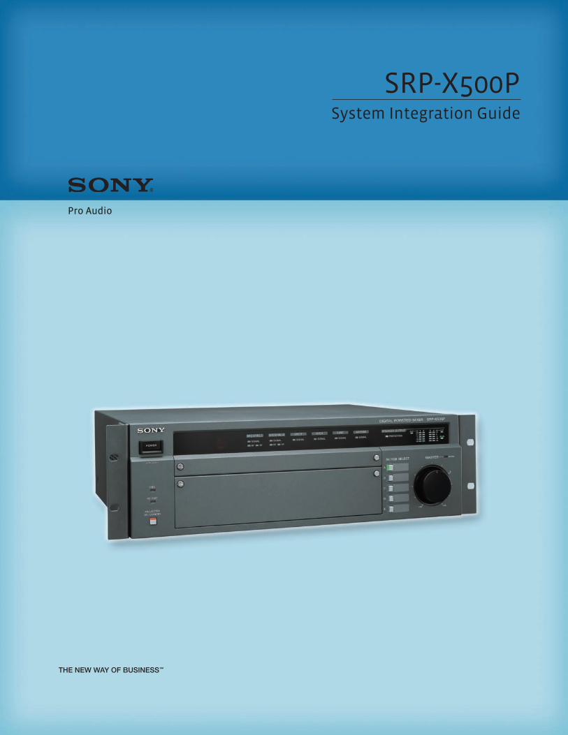
SRP-X500PSystem Integration Guide
Pro Audio
2
Table of Contents
1. Introduction ...................................................................................................... 3
2. Differences Between the SRP-X500P and SRP-X700P2-1. Features.................................................................................................... 4
2-2. Comparison Chart..................................................................................... 5
3. Panel View3-1. Front Panel ............................................................................................... 6
3-2. Rear Panel................................................................................................. 8
4. Setting up the SRP-X500P4-1. SYSTEM TYPE........................................................................................... 10
What is a “SYSTEM TYPE”?........................................................................ 10
SYSTEM TYPE 1, 2 (for AV Presentation Rooms) ........................................ 10
SYSTEM TYPE 4, 5 (for Conference Rooms) ............................................... 11
SYSTEM TYPE 3, 6, 7, 8, 9 (for Audio-Visual Rooms) .................................... 11
SYSTEM TYPE 0 ........................................................................................ 12
4-2. Feedback Reducer................................................................................... 13
5. Setting up the SRP-X500P Using Manager Software5-1. Automatic Gain Control (AGC) ................................................................. 14
5-2. Delay....................................................................................................... 15
5-3. Parallel Remote....................................................................................... 16
Connectable Devices to PARALLEL REMOTE Input Pins............................ 16
MASTER Volume Muting .......................................................................... 16
PROJECTOR POWER ON/STANDBY ............................................................ 17
Input Signal Selection for the AV/RGB INPUT Connector ......................... 18
MASTER Volume Control.......................................................................... 18
Scene Recall ............................................................................................ 19
Remote Fader Level Control .................................................................... 19
5-4. Projector Control .................................................................................... 20
Outline .................................................................................................... 20
Setting Procedure ................................................................................... 20
SECTION A: PROJECTOR PROTOCOL Select Switch Setting ....................... 21
SECTION B: Cable Connection ................................................................. 21
SECTION C: Input Video Signal Format and Projector Power Setting....... 22
SECTION D: Projector Control Using the Protocol Setting Function ........ 22
6. AppendixFeedback................................................................................................. 25
Automatic Gain Control (AGC).................................................................. 25
Effect of Delay......................................................................................... 26
Connecting High-impedance Speakers/Low-impedance Speakers .......... 27
Programming a Learning-type Remote Commander ............................... 27
Block Diagram ......................................................................................... 29
ASCII - HEX Conversion Table ................................................................... 30
Connecting Status LEDs on the Parallel Port ........................................... 30
System Configuration ............................................................................. 31
Specifications.......................................................................................... 32
Dimensions ............................................................................................. 32
3
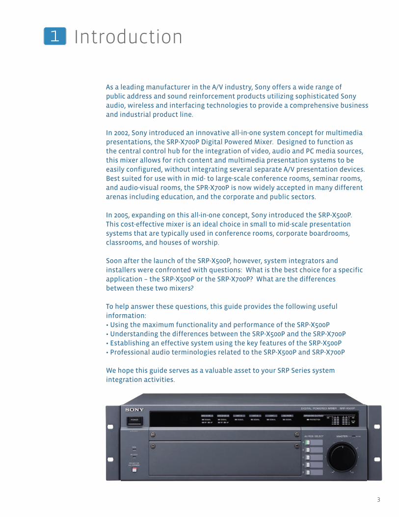
As a leading manufacturer in the A/V industry, Sony offers a wide range ofpublic address and sound reinforcement products utilizing sophisticated Sony audio, wireless and interfacing technologies to provide a comprehensive businessand industrial product line.
In 2002, Sony introduced an innovative all-in-one system concept for multimediapresentations, the SRP-X700P Digital Powered Mixer. Designed to function as the central control hub for the integration of video, audio and PC media sources, this mixer allows for rich content and multimedia presentation systems to be easily configured, without integrating several separate A/V presentation devices.Best suited for use with in mid- to large-scale conference rooms, seminar rooms, and audio-visual rooms, the SPR-X700P is now widely accepted in many differentarenas including education, and the corporate and public sectors.
In 2005, expanding on this all-in-one concept, Sony introduced the SRP-X500P.This cost-effective mixer is an ideal choice in small to mid-scale presentation systems that are typically used in conference rooms, corporate boardrooms,classrooms, and houses of worship.
Soon after the launch of the SRP-X500P, however, system integrators and installers were confronted with questions: What is the best choice for a specificapplication – the SRP-X500P or the SRP-X700P? What are the differences between these two mixers?
To help answer these questions, this guide provides the following useful information:• Using the maximum functionality and performance of the SRP-X500P• Understanding the differences between the SRP-X500P and the SRP-X700P• Establishing an effective system using the key features of the SRP-X500P• Professional audio terminologies related to the SRP-X500P and SRP-X700P
We hope this guide serves as a valuable asset to your SRP Series system integration activities.
1 Introduction
4
SRP-X500P System Integration Guide
2 Differences Between the SRP-X500P and SRP-X700P
2-1. Features
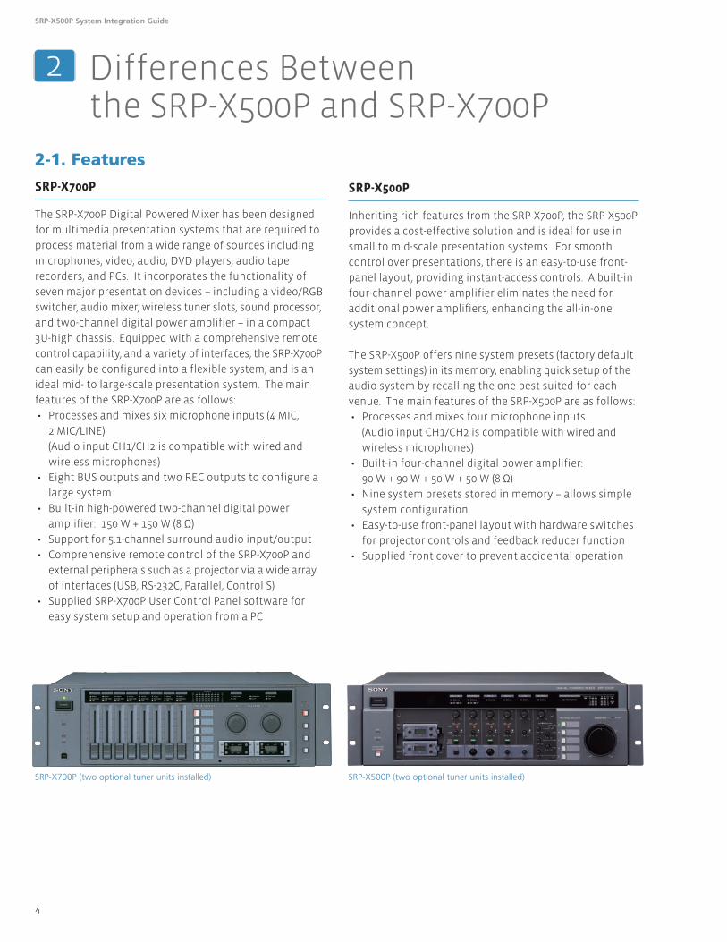
SRP-X700P
The SRP-X700P Digital Powered Mixer has been designed
for multimedia presentation systems that are required to
process material from a wide range of sources including
microphones, video, audio, DVD players, audio tape
recorders, and PCs. It incorporates the functionality of
seven major presentation devices – including a video/RGB
switcher, audio mixer, wireless tuner slots, sound processor,
and two-channel digital power amplifier – in a compact
3U-high chassis. Equipped with a comprehensive remote
control capability, and a variety of interfaces, the SRP-X700P
can easily be configured into a flexible system, and is an
ideal mid- to large-scale presentation system. The main
features of the SRP-X700P are as follows:
• Processes and mixes six microphone inputs (4 MIC,
2 MIC/LINE)
(Audio input CH1/CH2 is compatible with wired and
wireless microphones)
• Eight BUS outputs and two REC outputs to configure a
large system
• Built-in high-powered two-channel digital power
amplifier: 150 W + 150 W (8 Ω)
• Support for 5.1-channel surround audio input/output
• Comprehensive remote control of the SRP-X700P and
external peripherals such as a projector via a wide array
of interfaces (USB, RS-232C, Parallel, Control S)
• Supplied SRP-X700P User Control Panel software for
easy system setup and operation from a PC
SRP-X500P
Inheriting rich features from the SRP-X700P, the SRP-X500P
provides a cost-effective solution and is ideal for use in
small to mid-scale presentation systems. For smooth
control over presentations, there is an easy-to-use front-
panel layout, providing instant-access controls. A built-in
four-channel power amplifier eliminates the need for
additional power amplifiers, enhancing the all-in-one
system concept.
The SRP-X500P offers nine system presets (factory default
system settings) in its memory, enabling quick setup of the
audio system by recalling the one best suited for each
venue. The main features of the SRP-X500P are as follows:
• Processes and mixes four microphone inputs
(Audio input CH1/CH2 is compatible with wired and
wireless microphones)
• Built-in four-channel digital power amplifier:
90 W + 90 W + 50 W + 50 W (8 Ω)
• Nine system presets stored in memory – allows simple
system configuration
• Easy-to-use front-panel layout with hardware switches
for projector controls and feedback reducer function
• Supplied front cover to prevent accidental operation
SRP-X500P (two optional tuner units installed)SRP-X700P (two optional tuner units installed)
5
2 Differences Between the SRP-X500P and SRP-X700P
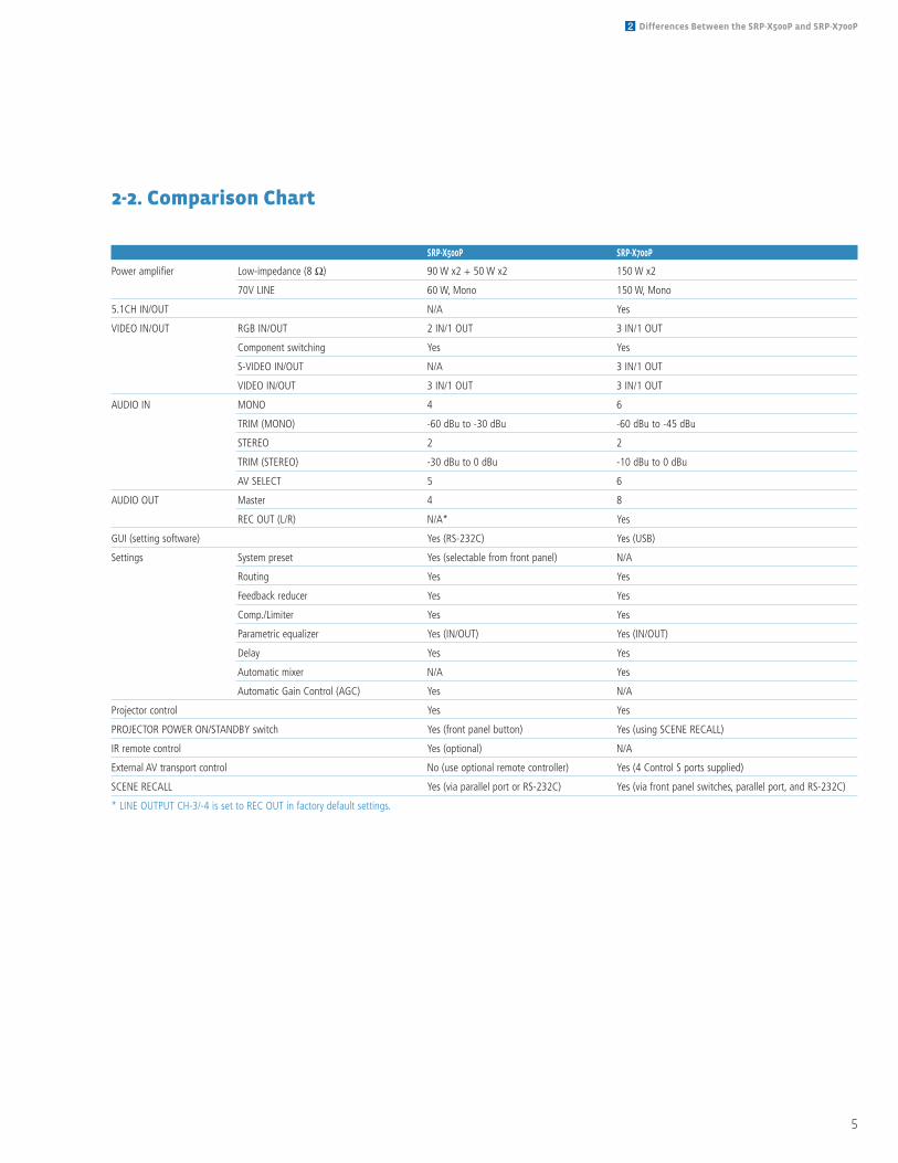
2-2. Comparison Chart
SRP-X500P SRP-X700P
Power amplifier Low-impedance (8 Ω) 90 W x2 + 50 W x2 150 W x2
70V LINE 60 W, Mono 150 W, Mono
5.1CH IN/OUT N/A Yes
VIDEO IN/OUT RGB IN/OUT 2 IN/1 OUT 3 IN/1 OUT
Component switching Yes Yes
S-VIDEO IN/OUT N/A 3 IN/1 OUT
VIDEO IN/OUT 3 IN/1 OUT 3 IN/1 OUT
AUDIO IN MONO 4 6
TRIM (MONO) -60 dBu to -30 dBu -60 dBu to -45 dBu
STEREO 2 2
TRIM (STEREO) -30 dBu to 0 dBu -10 dBu to 0 dBu
AV SELECT 5 6
AUDIO OUT Master 4 8
REC OUT (L/R) N/A* Yes
GUI (setting software) Yes (RS-232C) Yes (USB)
Settings System preset Yes (selectable from front panel) N/A
Routing Yes Yes
Feedback reducer Yes Yes
Comp./Limiter Yes Yes
Parametric equalizer Yes (IN/OUT) Yes (IN/OUT)
Delay Yes Yes
Automatic mixer N/A Yes
Automatic Gain Control (AGC) Yes N/A
Projector control Yes Yes
PROJECTOR POWER ON/STANDBY switch Yes (front panel button) Yes (using SCENE RECALL)
IR remote control Yes (optional) N/A
External AV transport control No (use optional remote controller) Yes (4 Control S ports supplied)
SCENE RECALL Yes (via parallel port or RS-232C) Yes (via front panel switches, parallel port, and RS-232C)
* LINE OUTPUT CH-3/-4 is set to REC OUT in factory default settings.
6
SRP-X500P System Integration Guide
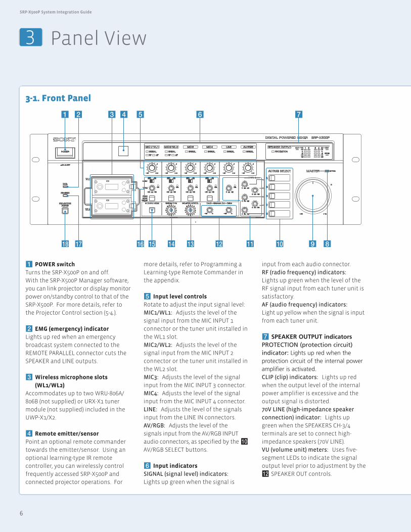
3-1. Front Panel
1 POWER switch
Turns the SRP-X500P on and off.
With the SRP-X500P Manager software,
you can link projector or display monitor
power on/standby control to that of the
SRP-X500P. For more details, refer to
the Projector Control section (5-4.).
2 EMG (emergency) indicator
Lights up red when an emergency
broadcast system connected to the
REMOTE PARALLEL connector cuts the
SPEAKER and LINE outputs.
3 Wireless microphone slots
(WL1/WL2)
Accommodates up to two WRU-806A/
806B (not supplied) or URX-X1 tuner
module (not supplied) included in the
UWP-X1/X2.
4 Remote emitter/sensor
Point an optional remote commander
towards the emitter/sensor. Using an
optional learning-type IR remote
controller, you can wirelessly control
frequently accessed SRP-X500P and
connected projector operations. For
more details, refer to Programming a
Learning-type Remote Commander in
the appendix.
5 Input level controls
Rotate to adjust the input signal level:
MIC1/WL1: Adjusts the level of the
signal input from the MIC INPUT 1
connector or the tuner unit installed in
the WL1 slot.
MIC2/WL2: Adjusts the level of the
signal input from the MIC INPUT 2
connector or the tuner unit installed in
the WL2 slot.
MIC3: Adjusts the level of the signal
input from the MIC INPUT 3 connector.
MIC4: Adjusts the level of the signal
input from the MIC INPUT 4 connector.
LINE: Adjusts the level of the signals
input from the LINE IN connectors.
AV/RGB: Adjusts the level of the
signals input from the AV/RGB INPUT
audio connectors, as specified by the0
AV/RGB SELECT buttons.
6 Input indicators
SIGNAL (signal level) indicators:
Lights up green when the signal is
3 Panel View
input from each audio connector.
RF (radio frequency) indicators:
Lights up green when the level of the
RF signal input from each tuner unit is
satisfactory.
AF (audio frequency) indicators:
Light up yellow when the signal is input
from each tuner unit.
7 SPEAKER OUTPUT indicatorsPROTECTION (protection circuit)indicator: Lights up red when theprotection circuit of the internal poweramplifier is activated.CLIP (clip) indicators: Lights up red
when the output level of the internal
power amplifier is excessive and the
output signal is distorted.
70V LINE (high-impedance speaker
connection) indicator: Lights up
green when the SPEAKERS CH-3/4
terminals are set to connect high-
impedance speakers (70V LINE).
VU (volume unit) meters: Uses five-
segment LEDs to indicate the signal
output level prior to adjustment by the
!™ SPEAKER OUT controls.
!• !¶ !§ !¢ !£ !™ !¡ !º 9 8
7654321
!∞
7
3 Panel View
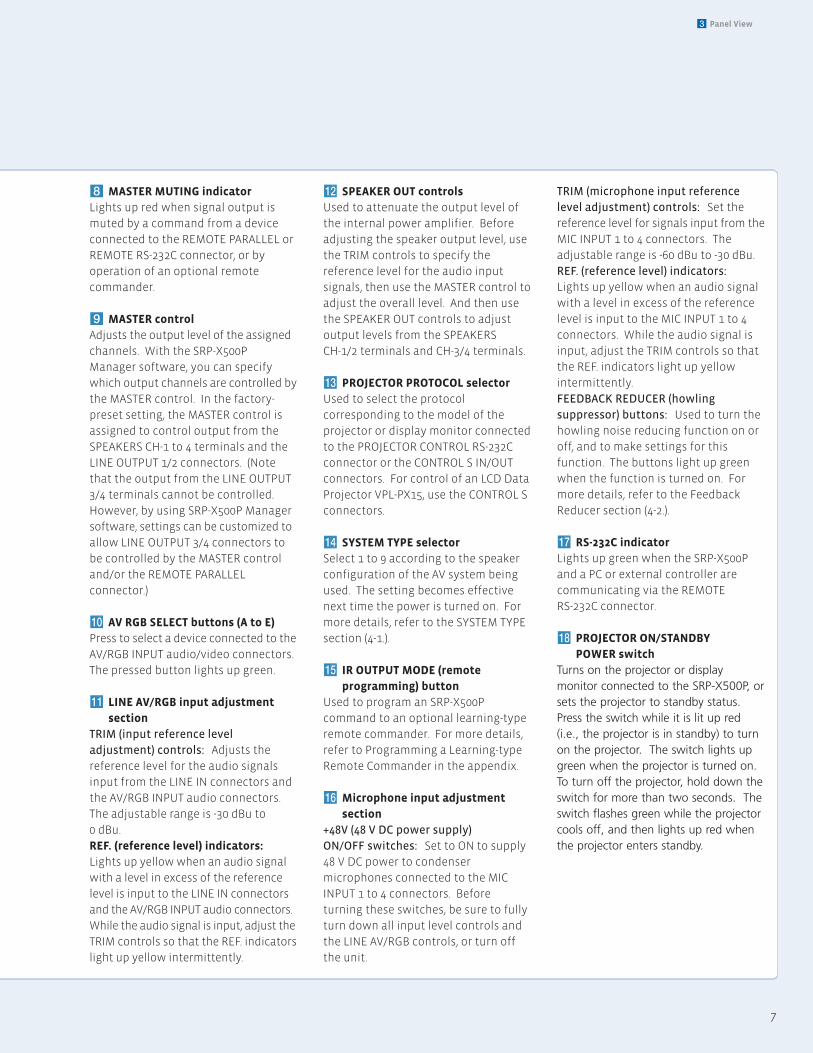
8 MASTER MUTING indicator
Lights up red when signal output is
muted by a command from a device
connected to the REMOTE PARALLEL or
REMOTE RS-232C connector, or by
operation of an optional remote
commander.
9 MASTER control
Adjusts the output level of the assigned
channels. With the SRP-X500P
Manager software, you can specify
which output channels are controlled by
the MASTER control. In the factory-
preset setting, the MASTER control is
assigned to control output from the
SPEAKERS CH-1 to 4 terminals and the
LINE OUTPUT 1/2 connectors. (Note
that the output from the LINE OUTPUT
3/4 terminals cannot be controlled.
However, by using SRP-X500P Manager
software, settings can be customized to
allow LINE OUTPUT 3/4 connectors to
be controlled by the MASTER control
and/or the REMOTE PARALLEL
connector.)
!º AV RGB SELECT buttons (A to E)
Press to select a device connected to the
AV/RGB INPUT audio/video connectors.
The pressed button lights up green.
!¡ LINE AV/RGB input adjustment
section
TRIM (input reference level
adjustment) controls: Adjusts the
reference level for the audio signals
input from the LINE IN connectors and
the AV/RGB INPUT audio connectors.
The adjustable range is -30 dBu to
0 dBu.
REF. (reference level) indicators:
Lights up yellow when an audio signal
with a level in excess of the reference
level is input to the LINE IN connectors
and the AV/RGB INPUT audio connectors.
While the audio signal is input, adjust the
TRIM controls so that the REF. indicators
light up yellow intermittently.
!™ SPEAKER OUT controls
Used to attenuate the output level of
the internal power amplifier. Before
adjusting the speaker output level, use
the TRIM controls to specify the
reference level for the audio input
signals, then use the MASTER control to
adjust the overall level. And then use
the SPEAKER OUT controls to adjust
output levels from the SPEAKERS
CH-1/2 terminals and CH-3/4 terminals.
!£ PROJECTOR PROTOCOL selector
Used to select the protocol
corresponding to the model of the
projector or display monitor connected
to the PROJECTOR CONTROL RS-232C
connector or the CONTROL S IN/OUT
connectors. For control of an LCD Data
Projector VPL-PX15, use the CONTROL S
connectors.
!¢ SYSTEM TYPE selector
Select 1 to 9 according to the speaker
configuration of the AV system being
used. The setting becomes effective
next time the power is turned on. For
more details, refer to the SYSTEM TYPE
section (4-1.).
!∞ IR OUTPUT MODE (remote
programming) button
Used to program an SRP-X500P
command to an optional learning-type
remote commander. For more details,
refer to Programming a Learning-type
Remote Commander in the appendix.
!§ Microphone input adjustment
section
+48V (48 V DC power supply)
ON/OFF switches: Set to ON to supply
48 V DC power to condenser
microphones connected to the MIC
INPUT 1 to 4 connectors. Before
turning these switches, be sure to fully
turn down all input level controls and
the LINE AV/RGB controls, or turn off
the unit.
TRIM (microphone input reference
level adjustment) controls: Set the
reference level for signals input from the
MIC INPUT 1 to 4 connectors. The
adjustable range is -60 dBu to -30 dBu.
REF. (reference level) indicators:
Lights up yellow when an audio signal
with a level in excess of the reference
level is input to the MIC INPUT 1 to 4
connectors. While the audio signal is
input, adjust the TRIM controls so that
the REF. indicators light up yellow
intermittently.
FEEDBACK REDUCER (howling
suppressor) buttons: Used to turn the
howling noise reducing function on or
off, and to make settings for this
function. The buttons light up green
when the function is turned on. For
more details, refer to the Feedback
Reducer section (4-2.).
!¶ RS-232C indicator
Lights up green when the SRP-X500P
and a PC or external controller are
communicating via the REMOTE
RS-232C connector.
!• PROJECTOR ON/STANDBY
POWER switch
Turns on the projector or displaymonitor connected to the SRP-X500P, orsets the projector to standby status.Press the switch while it is lit up red(i.e., the projector is in standby) to turnon the projector. The switch lights upgreen when the projector is turned on.To turn off the projector, hold down theswitch for more than two seconds. Theswitch flashes green while the projectorcools off, and then lights up red whenthe projector enters standby.
8
SRP-X500P System Integration Guide
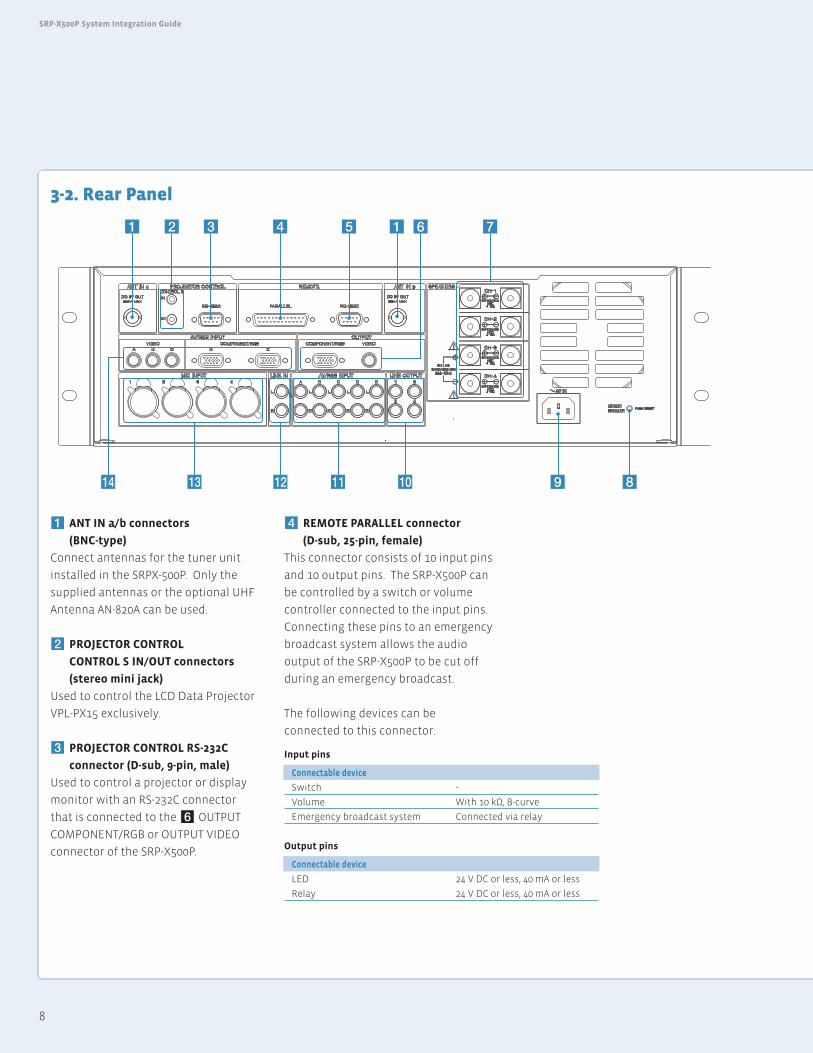
3-2. Rear Panel
1 ANT IN a/b connectors
(BNC-type)
Connect antennas for the tuner unit
installed in the SRPX-500P. Only the
supplied antennas or the optional UHF
Antenna AN-820A can be used.
2 PROJECTOR CONTROL
CONTROL S IN/OUT connectors
(stereo mini jack)
Used to control the LCD Data Projector
VPL-PX15 exclusively.
3 PROJECTOR CONTROL RS-232C
connector (D-sub, 9-pin, male)
Used to control a projector or display
monitor with an RS-232C connector
that is connected to the 6 OUTPUT
COMPONENT/RGB or OUTPUT VIDEO
connector of the SRP-X500P.
4 REMOTE PARALLEL connector
(D-sub, 25-pin, female)
This connector consists of 10 input pins
and 10 output pins. The SRP-X500P can
be controlled by a switch or volume
controller connected to the input pins.
Connecting these pins to an emergency
broadcast system allows the audio
output of the SRP-X500P to be cut off
during an emergency broadcast.
The following devices can be
connected to this connector:
!¢ !£ !™ !¡ !º 9 8
71 654321
Input pins
Connectable device
Switch -
Volume With 10 kΩ, B-curve
Emergency broadcast system Connected via relay
Output pins
Connectable device
LED 24 V DC or less, 40 mA or less
Relay 24 V DC or less, 40 mA or less
9
3 Panel View
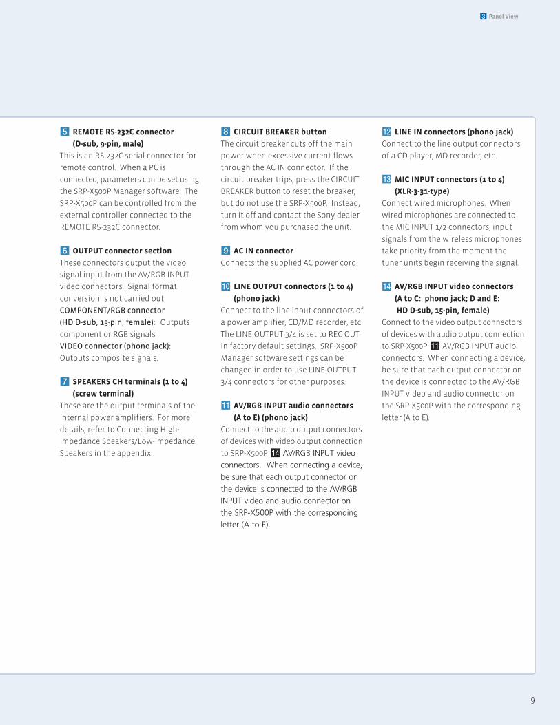
5 REMOTE RS-232C connector
(D-sub, 9-pin, male)
This is an RS-232C serial connector for
remote control. When a PC is
connected, parameters can be set using
the SRP-X500P Manager software. The
SRP-X500P can be controlled from the
external controller connected to the
REMOTE RS-232C connector.
6 OUTPUT connector section
These connectors output the video
signal input from the AV/RGB INPUT
video connectors. Signal format
conversion is not carried out.
COMPONENT/RGB connector
(HD D-sub, 15-pin, female): Outputs
component or RGB signals.
VIDEO connector (phono jack):
Outputs composite signals.
7 SPEAKERS CH terminals (1 to 4)
(screw terminal)
These are the output terminals of the
internal power amplifiers. For more
details, refer to Connecting High-
impedance Speakers/Low-impedance
Speakers in the appendix.
8 CIRCUIT BREAKER button
The circuit breaker cuts off the main
power when excessive current flows
through the AC IN connector. If the
circuit breaker trips, press the CIRCUIT
BREAKER button to reset the breaker,
but do not use the SRP-X500P. Instead,
turn it off and contact the Sony dealer
from whom you purchased the unit.
9 AC IN connector
Connects the supplied AC power cord.
!º LINE OUTPUT connectors (1 to 4)
(phono jack)
Connect to the line input connectors of
a power amplifier, CD/MD recorder, etc.
The LINE OUTPUT 3/4 is set to REC OUT
in factory default settings. SRP-X500P
Manager software settings can be
changed in order to use LINE OUTPUT
3/4 connectors for other purposes.
!¡ AV/RGB INPUT audio connectors
(A to E) (phono jack)
Connect to the audio output connectors
of devices with video output connection
to SRP-X500P !¢ AV/RGB INPUT video
connectors. When connecting a device,
be sure that each output connector on
the device is connected to the AV/RGB
INPUT video and audio connector on
the SRP-X500P with the corresponding
letter (A to E).
!™ LINE IN connectors (phono jack)
Connect to the line output connectors
of a CD player, MD recorder, etc.
!£ MIC INPUT connectors (1 to 4)
(XLR-3-31-type)
Connect wired microphones. When
wired microphones are connected to
the MIC INPUT 1/2 connectors, input
signals from the wireless microphones
take priority from the moment the
tuner units begin receiving the signal.
!¢ AV/RGB INPUT video connectors
(A to C: phono jack; D and E:
HD D-sub, 15-pin, female)
Connect to the video output connectors
of devices with audio output connection
to SRP-X500P !¡ AV/RGB INPUT audio
connectors. When connecting a device,
be sure that each output connector on
the device is connected to the AV/RGB
INPUT video and audio connector on
the SRP-X500P with the corresponding
letter (A to E).
10
SRP-X500P System Integration Guide
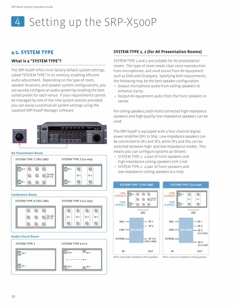
4-1. SYSTEM TYPE
What is a “SYSTEM TYPE”?
The SRP-X500P offers nine factory default system settings
called “SYSTEM TYPE” in its memory, enabling efficient
audio adjustment. Depending on the type of room,
speaker locations, and speaker system configurations, you
can quickly configure an audio system by recalling the best-
suited preset for each venue. If your requirements cannot
be managed by one of the nine system presets provided,
you can easily customize all system settings using the
supplied SRP-X500P Manager software.
SYSTEM TYPE 1, 2 (for AV Presentation Rooms)
SYSTEM TYPE 1 and 2 are suitable for AV presentation
rooms. This type of room needs clear voice reproduction
from microphones, and vivid sound from AV equipment
such as DVD and CD players. Satisfying both requirements,
the following may be the best speaker configuration:
• Output microphone audio from ceiling speakers to
enhance clarity
• Output AV equipment audio from the front speakers in
stereo
For ceiling speakers, both multi-connected high-impedance
speakers and high-quality low-impedance speakers can be
used.
The SRP-X500P is equipped with a four-channel digital
power amplifier (SP1 to SP4). Low-impedance speakers can
be connected to SP1 and SP2, while SP3 and SP4 can be
switched between high- and low-impedance modes. This
means you can configure systems as follows:
• SYSTEM TYPE 1: a pair of front speakers and
high-impedance ceiling speakers (70V Line)
• SYSTEM TYPE 2: a pair of front speakers and
low-impedance ceiling speakers (Lo-imp)
4 Setting up the SRP-X500P
SP 2
70V LINE(SP 3-4)
SP 1
SP 2
SP 3 SP 4
SP 1
SP 2
SP 1
SP 2
SP 1 SP 3
SP 4
A
70V LINE(SP 3-4) SP 1 SP 2 SP 3 SP 4
AV Presentaion Room
SYSTEM TYPE 1 (70V LINE)
SYSTEM TYPE 4 (70V LINE)
SYSTEM TYPE 2 (Lo-imp)
SYSTEM TYPE 5 (Lo-imp)
SYSTEM TYPE 3 SYSTEM TYPE 6 to 9
Conference Room
Audio-Visual Room
SP 2
70V LINE(SP 3-4)
SP 1
SP 2
SP 3 SP 4
SP 1
SYSTEM TYPE 1 (70V LINE) SYSTEM TYPE 2 (Lo-imp)
LINE,AV/RGB R
LINE,AV/RGB L
LINE,AV/RGB R
LINE,AV/RGB L
MIC
MIC
MIC
LINE
AV/RGB
MIC
LINE
AV/RGB
SRP-X500P SRP-X500P
SP 1
SP 2
SP 1
SP 2
SP 3-4(70V LINE)
IN OUTIN OUT
When using high-impedance ceiling speakers
SP 3(Lo-imp)
SP 4(Lo-imp)
When using low-impedance ceiling speakers
11
4 Setting up the SRP-X500P
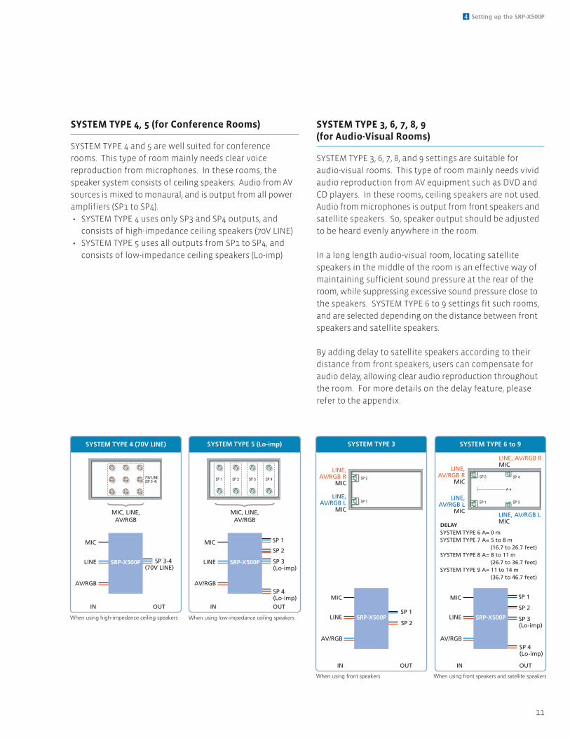
SYSTEM TYPE 4, 5 (for Conference Rooms)
SYSTEM TYPE 4 and 5 are well suited for conference
rooms. This type of room mainly needs clear voice
reproduction from microphones. In these rooms, the
speaker system consists of ceiling speakers. Audio from AV
sources is mixed to monaural, and is output from all power
amplifiers (SP1 to SP4).
• SYSTEM TYPE 4 uses only SP3 and SP4 outputs, and
consists of high-impedance ceiling speakers (70V LINE)
• SYSTEM TYPE 5 uses all outputs from SP1 to SP4, and
consists of low-impedance ceiling speakers (Lo-imp)
SYSTEM TYPE 3, 6, 7, 8, 9 (for Audio-Visual Rooms)
SYSTEM TYPE 3, 6, 7, 8, and 9 settings are suitable for
audio-visual rooms. This type of room mainly needs vivid
audio reproduction from AV equipment such as DVD and
CD players. In these rooms, ceiling speakers are not used.
Audio from microphones is output from front speakers and
satellite speakers. So, speaker output should be adjusted
to be heard evenly anywhere in the room.
In a long length audio-visual room, locating satellite
speakers in the middle of the room is an effective way of
maintaining sufficient sound pressure at the rear of the
room, while suppressing excessive sound pressure close to
the speakers. SYSTEM TYPE 6 to 9 settings fit such rooms,
and are selected depending on the distance between front
speakers and satellite speakers.
By adding delay to satellite speakers according to their
distance from front speakers, users can compensate for
audio delay, allowing clear audio reproduction throughout
the room. For more details on the delay feature, please
refer to the appendix.
SP 2
SP 1
SP 2
SP 1 SP 3
SP 4
A
SYSTEM TYPE 3 SYSTEM TYPE 6 to 9
LINE,AV/RGB R
MIC
LINE,AV/RGB L
MIC
LINE,AV/RGB R
MIC
LINE, AV/RGB RMIC
LINE,AV/RGB L
MICLINE, AV/RGB LMIC
MIC
LINE
AV/RGB
MIC
LINE
AV/RGB
SRP-X500P SRP-X500P
SP 1
SP 2SP 1
SP 2SP 3(Lo-imp)
SP 4(Lo-imp)
When using front speakers When using front speakers and satellite speakers
DELAYSYSTEM TYPE 6 A= 0 mSYSTEM TYPE 7 A= 5 to 8 m (16.7 to 26.7 feet)SYSTEM TYPE 8 A= 8 to 11 m (26.7 to 36.7 feet)SYSTEM TYPE 9 A= 11 to 14 m (36.7 to 46.7 feet)
IN OUTIN OUT
70V LINE(SP 3-4) SP 1 SP 2 SP 3 SP 4
SYSTEM TYPE 4 (70V LINE) SYSTEM TYPE 5 (Lo-imp)
MIC
LINE
AV/RGB
MIC
LINE
AV/RGB
SRP-X500P SRP-X500P
SP 1
SP 2
SP 3-4(70V LINE)
When using high-impedance ceiling speakers
SP 3(Lo-imp)
SP 4(Lo-imp)
When using low-impedance ceiling speakers
MIC, LINE,AV/RGB
MIC, LINE,AV/RGB
IN OUT IN OUT
12
SRP-X500P System Integration Guide
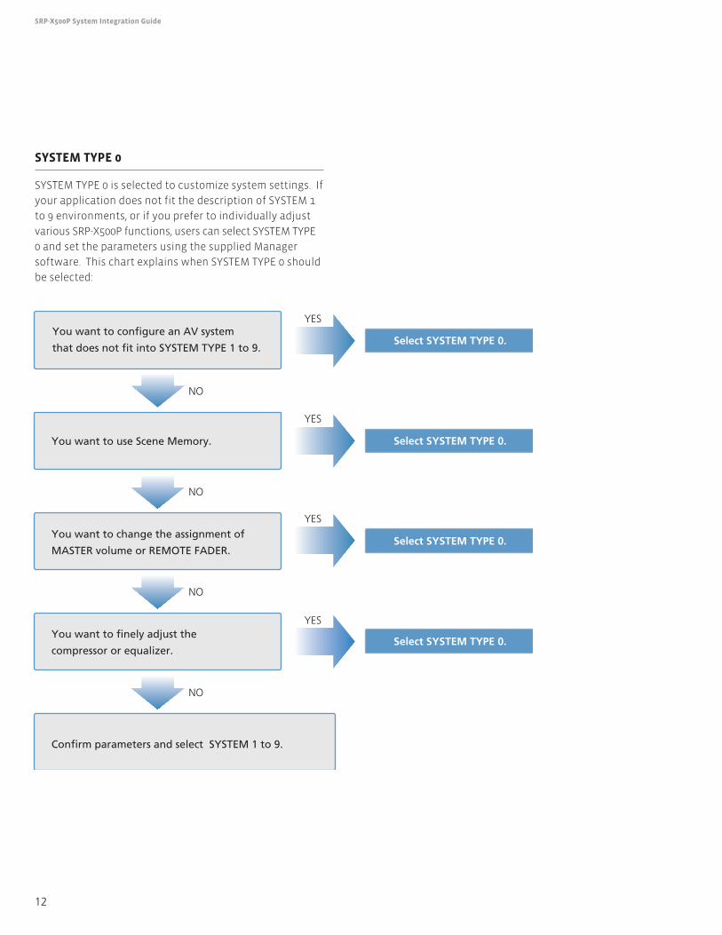
SYSTEM TYPE 0
SYSTEM TYPE 0 is selected to customize system settings. If
your application does not fit the description of SYSTEM 1
to 9 environments, or if you prefer to individually adjust
various SRP-X500P functions, users can select SYSTEM TYPE
0 and set the parameters using the supplied Manager
software. This chart explains when SYSTEM TYPE 0 should
be selected:
NO
YES
YES
YES
YES
NO
NO
NO
You want to configure an AV system
that does not fit into SYSTEM TYPE 1 to 9.Select SYSTEM TYPE 0.
Select SYSTEM TYPE 0.
Select SYSTEM TYPE 0.
Select SYSTEM TYPE 0.
Confirm parameters and select SYSTEM 1 to 9.
You want to finely adjust the
compressor or equalizer.
You want to change the assignment of
MASTER volume or REMOTE FADER.
You want to use Scene Memory.
13
4 Setting up the SRP-X500P
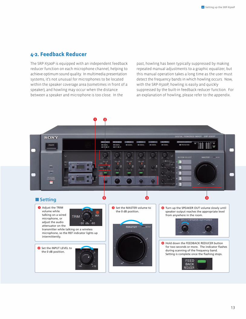
4-2. Feedback Reducer
The SRP-X500P is equipped with an independent feedback
reducer function on each microphone channel, helping to
achieve optimum sound quality. In multimedia presentation
systems, it’s not unusual for microphones to be located
within the speaker coverage area (sometimes in front of a
speaker), and howling may occur when the distance
between a speaker and microphone is too close. In the
past, howling has been typically suppressed by making
repeated manual adjustments to a graphic equalizer, but
this manual operation takes a long time as the user must
detect the frequency bands in which howling occurs. Now,
with the SRP-X500P, howling is easily and quickly
suppressed by the built-in feedback reducer function. For
an explanation of howling, please refer to the appendix.
1 Adjust the TRIM volume while talking on a wired microphone, or adjust the audio attenuator on the transmitter while talking on a wireless microphone, so the REF indicator lights up intermittently.
2 Set the INPUT LEVEL to the 0 dB position.
3 Set the MASTER volume to the 0 dB position.
4 Turn up the SPEAKER OUT volume slowly until speaker output reaches the appropriate level from anywhere in the room.
5 Hold down the FEEDBACK REDUCER button for two seconds or more. The indicator flashes during scanning of the frequency band. Setting is complete once the flashing stops.
2
5 4 3
1
n Setting
14
SRP-X500P System Integration Guide
5-1. Automatic Gain Control (AGC)
It is often difficult to appropriately adjust microphone
volumes when picking up voice. This is because speaking
volumes differ from person to person, and depend on the
distance between each presenter’s mouth and the
microphone. The Automatic Gain Control (AGC) function
is convenient for maintaining an optimum audio level by
reducing speech volume differences. AGC can be set using
the supplied SRP-X500P Manager software. For more
details on AGC, refer to the appendix.
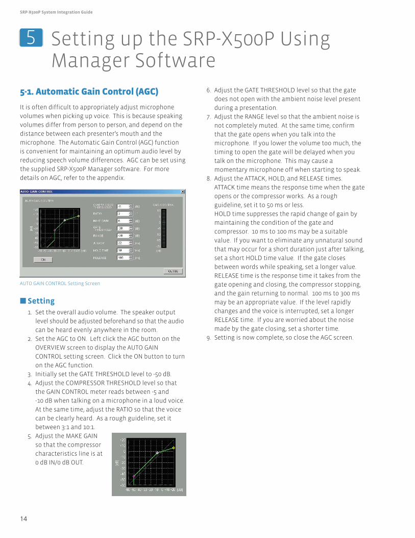
n Setting1. Set the overall audio volume. The speaker output
level should be adjusted beforehand so that the audio
can be heard evenly anywhere in the room.
2. Set the AGC to ON. Left click the AGC button on the
OVERVIEW screen to display the AUTO GAIN
CONTROL setting screen. Click the ON button to turn
on the AGC function.
3. Initially set the GATE THRESHOLD level to -50 dB.
4. Adjust the COMPRESSOR THRESHOLD level so that
the GAIN CONTROL meter reads between -5 and
-10 dB when talking on a microphone in a loud voice.
At the same time, adjust the RATIO so that the voice
can be clearly heard. As a rough guideline, set it
between 3:1 and 10:1.
5. Adjust the MAKE GAIN
so that the compressor
characteristics line is at
0 dB IN/0 dB OUT.
6. Adjust the GATE THRESHOLD level so that the gate
does not open with the ambient noise level present
during a presentation.
7. Adjust the RANGE level so that the ambient noise is
not completely muted. At the same time, confirm
that the gate opens when you talk into the
microphone. If you lower the volume too much, the
timing to open the gate will be delayed when you
talk on the microphone. This may cause a
momentary microphone off when starting to speak.
8. Adjust the ATTACK, HOLD, and RELEASE times.
ATTACK time means the response time when the gate
opens or the compressor works. As a rough
guideline, set it to 50 ms or less.
HOLD time suppresses the rapid change of gain by
maintaining the condition of the gate and
compressor. 10 ms to 100 ms may be a suitable
value. If you want to eliminate any unnatural sound
that may occur for a short duration just after talking,
set a short HOLD time value. If the gate closes
between words while speaking, set a longer value.
RELEASE time is the response time it takes from the
gate opening and closing, the compressor stopping,
and the gain returning to normal. 100 ms to 300 ms
may be an appropriate value. If the level rapidly
changes and the voice is interrupted, set a longer
RELEASE time. If you are worried about the noise
made by the gate closing, set a shorter time.
9. Setting is now complete, so close the AGC screen.
5 Setting up the SRP-X500P UsingManager Software
AUTO GAIN CONTROL Setting Screen
15
5 Setting up the SRP-X500P Using Manager Software
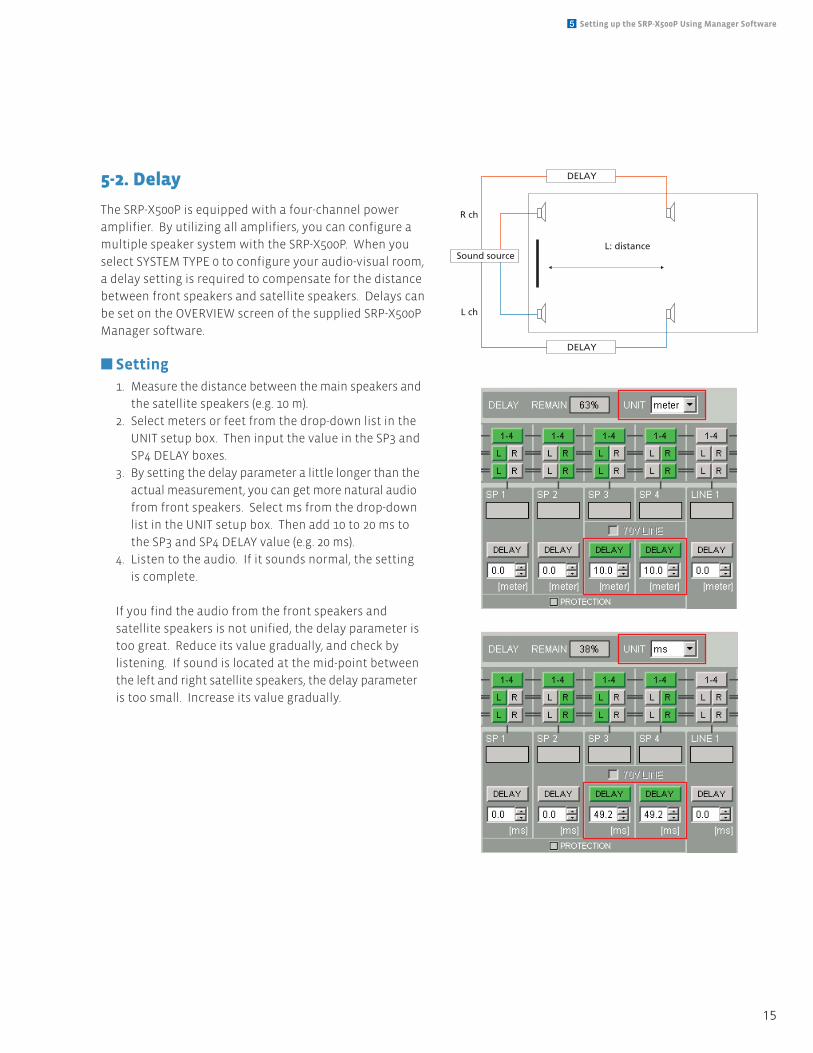
5-2. Delay
The SRP-X500P is equipped with a four-channel power
amplifier. By utilizing all amplifiers, you can configure a
multiple speaker system with the SRP-X500P. When you
select SYSTEM TYPE 0 to configure your audio-visual room,
a delay setting is required to compensate for the distance
between front speakers and satellite speakers. Delays can
be set on the OVERVIEW screen of the supplied SRP-X500P
Manager software.
n Setting1. Measure the distance between the main speakers and
the satellite speakers (e.g. 10 m).
2. Select meters or feet from the drop-down list in the
UNIT setup box. Then input the value in the SP3 and
SP4 DELAY boxes.
3. By setting the delay parameter a little longer than the
actual measurement, you can get more natural audio
from front speakers. Select ms from the drop-down
list in the UNIT setup box. Then add 10 to 20 ms to
the SP3 and SP4 DELAY value (e.g. 20 ms).
4. Listen to the audio. If it sounds normal, the setting
is complete.
If you find the audio from the front speakers and
satellite speakers is not unified, the delay parameter is
too great. Reduce its value gradually, and check by
listening. If sound is located at the mid-point between
the left and right satellite speakers, the delay parameter
is too small. Increase its value gradually.
Sound source
R ch
DELAY
DELAY
L: distance
L ch
16
SRP-X500P System Integration Guide
5-3. Parallel Remote
When the SRP-X500P is installed in a presentation room,
the external control panel can be used to remotely control
AV equipment.
The PARALLEL REMOTE interface on the rear panel of the
SRP-X500P allows remote control of peripherals from the
external control panel using switches and volume
controls.
Connectable Devices to PARALLEL REMOTE Input Pins
The following types of device can be connected to the
PARALLEL REMOTE:
• Toggle SwitchThe toggle switch is an electric switch operated by
pushing a latching-type lever. Pressing it once turns the
circuit on, and pressing it again turns the circuit off. The
toggle switch controls:
- Muting
- PROJECTOR POWER ON/STANDBY
• Push Switch (momentary-type)Press the push switch to turn on the circuit. The push
switch controls:
- Input signal selection for the AV/RGB INPUT
- MASTER VOLUME UP
- MASTER VOLUME DOWN
- SCENE RECALL
- PROJECTOR POWER ON
- PROJECTOR POWER STANDBY
• Control VolumeThe control volume is used to adjust REMOTE FADER.
Select the control volume with a 10 kΩ B curve. This
can be used to remotely control the volume of REMOTE
FADER LEVEL.
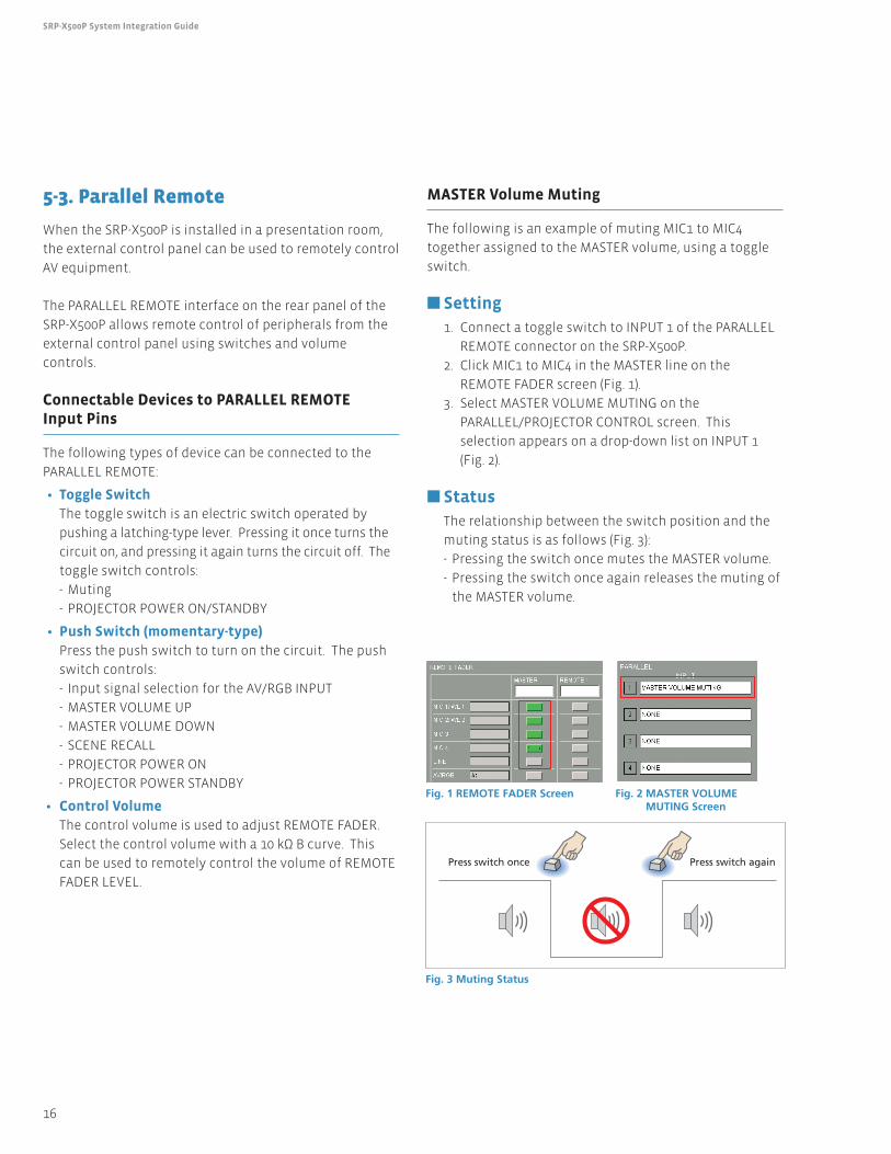
MASTER Volume Muting
The following is an example of muting MIC1 to MIC4
together assigned to the MASTER volume, using a toggle
switch.
n Setting1. Connect a toggle switch to INPUT 1 of the PARALLEL
REMOTE connector on the SRP-X500P.
2. Click MIC1 to MIC4 in the MASTER line on the
REMOTE FADER screen (Fig. 1).
3. Select MASTER VOLUME MUTING on the
PARALLEL/PROJECTOR CONTROL screen. This
selection appears on a drop-down list on INPUT 1
(Fig. 2).
n StatusThe relationship between the switch position and the
muting status is as follows (Fig. 3):
- Pressing the switch once mutes the MASTER volume.
- Pressing the switch once again releases the muting of
the MASTER volume.
Press switch once
Fig. 3 Muting Status
Fig. 1 REMOTE FADER Screen Fig. 2 MASTER VOLUME MUTING Screen
Press switch again
17
5 Setting up the SRP-X500P Using Manager Software
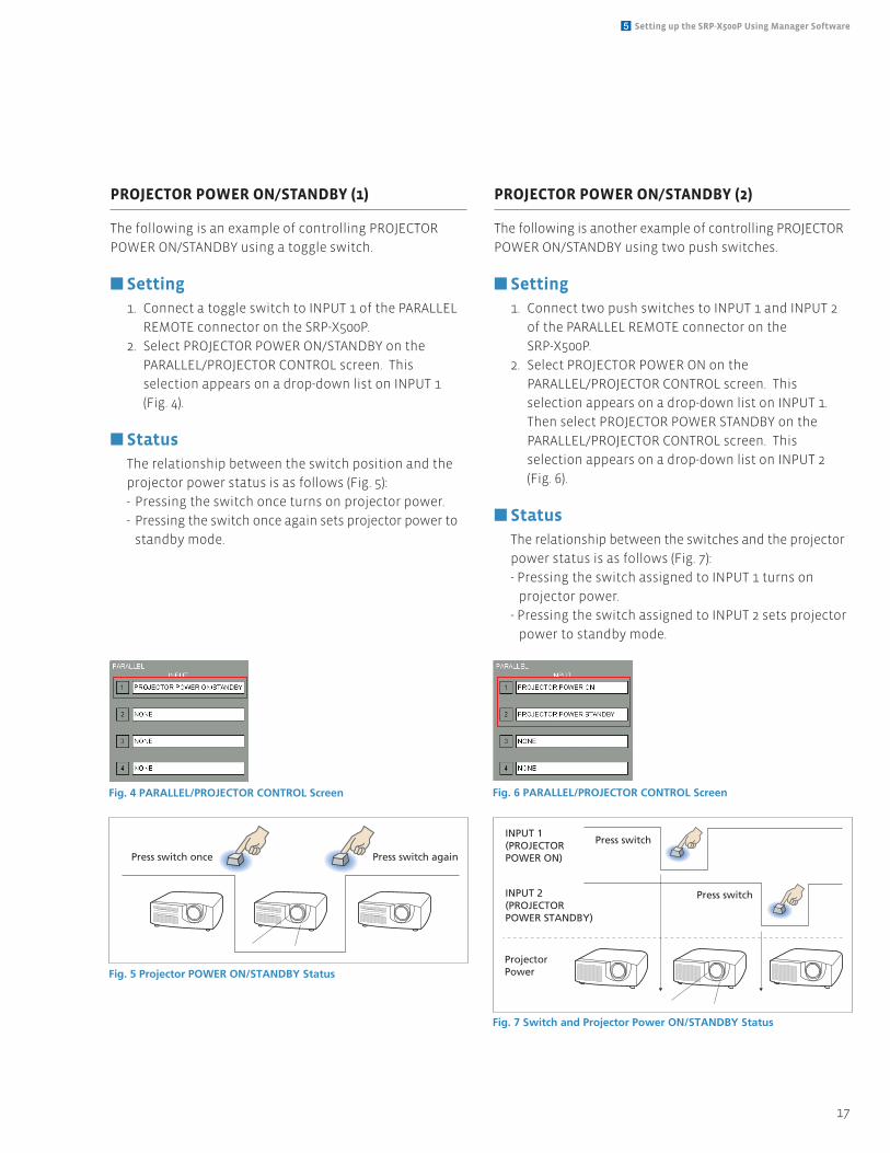
PROJECTOR POWER ON/STANDBY (1)
The following is an example of controlling PROJECTOR
POWER ON/STANDBY using a toggle switch.
n Setting1. Connect a toggle switch to INPUT 1 of the PARALLEL
REMOTE connector on the SRP-X500P.
2. Select PROJECTOR POWER ON/STANDBY on the
PARALLEL/PROJECTOR CONTROL screen. This
selection appears on a drop-down list on INPUT 1
(Fig. 4).
n StatusThe relationship between the switch position and the
projector power status is as follows (Fig. 5):
- Pressing the switch once turns on projector power.
- Pressing the switch once again sets projector power to
standby mode.
PROJECTOR POWER ON/STANDBY (2)
The following is another example of controlling PROJECTOR
POWER ON/STANDBY using two push switches.
n Setting1. Connect two push switches to INPUT 1 and INPUT 2
of the PARALLEL REMOTE connector on the
SRP-X500P.
2. Select PROJECTOR POWER ON on the
PARALLEL/PROJECTOR CONTROL screen. This
selection appears on a drop-down list on INPUT 1.
Then select PROJECTOR POWER STANDBY on the
PARALLEL/PROJECTOR CONTROL screen. This
selection appears on a drop-down list on INPUT 2
(Fig. 6).
n StatusThe relationship between the switches and the projector
power status is as follows (Fig. 7):
- Pressing the switch assigned to INPUT 1 turns on
projector power.
- Pressing the switch assigned to INPUT 2 sets projector
power to standby mode.
Press switch once
Fig. 5 Projector POWER ON/STANDBY Status
Fig. 4 PARALLEL/PROJECTOR CONTROL Screen
Press switch again
Press switch
Press switch
INPUT 1(PROJECTORPOWER ON)
INPUT 2(PROJECTORPOWER STANDBY)
ProjectorPower
Fig. 7 Switch and Projector Power ON/STANDBY Status
Fig. 6 PARALLEL/PROJECTOR CONTROL Screen
18
SRP-X500P System Integration Guide
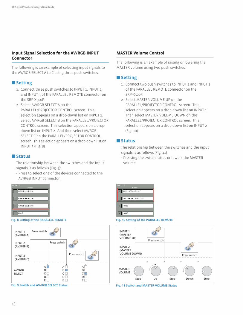
Input Signal Selection for the AV/RGB INPUTConnector
The following is an example of selecting input signals to
the AV/RGB SELECT A to C using three push switches.
n Setting1. Connect three push switches to INPUT 1, INPUT 2,
and INPUT 3 of the PARALLEL REMOTE connector on
the SRP-X500P.
2. Select AV/RGB SELECT A on the
PARALLEL/PROJECTOR CONTROL screen. This
selection appears on a drop-down list on INPUT 1.
Select AV/RGB SELECT B on the PARALLEL/PROJECTOR
CONTROL screen. This selection appears on a drop-
down list on INPUT 2. And then select AV/RGB
SELECT C on the PARALLEL/PROJECTOR CONTROL
screen. This selection appears on a drop-down list on
INPUT 3 (Fig. 8).
n StatusThe relationship between the switches and the input
signals is as follows (Fig. 9):
- Press to select one of the devices connected to the
AV/RGB INPUT connector.
MASTER Volume Control
The following is an example of raising or lowering the
MASTER volume using two push switches.
n Setting1. Connect two push switches to INPUT 1 and INPUT 2
of the PARALLEL REMOTE connector on the
SRP-X500P.
2. Select MASTER VOLUME UP on the
PARALLEL/PROJECTOR CONTROL screen. This
selection appears on a drop-down list on INPUT 1.
Then select MASTER VOLUME DOWN on the
PARALLEL/PROJECTOR CONTROL screen. This
selection appears on a drop-down list on INPUT 2
(Fig. 10).
n StatusThe relationship between the switches and the input
signals is as follows (Fig. 11):
- Pressing the switch raises or lowers the MASTER
volume.
Press switch
Press switch
Press switch
INPUT 1(AV/RGB A)
INPUT 2(AV/RGB B)
INPUT 3(AV/RGB C)
AV/RGBSELECT
Fig. 9 Switch and AV/RGB SELECT Status
Fig. 8 Setting of the PARALLEL REMOTE
ABCDE
ABCDE
ABCDE
Press switch
Press switch
StopDownStopUpStop
INPUT 1(MASTERVOLUME UP)
INPUT 2(MASTERVOLUME DOWN)
MASTERVOLUME
Fig. 11 Switch and MASTER VOLUME Status
Fig. 10 Setting of the PARALLEL REMOTE
19
5 Setting up the SRP-X500P Using Manager Software
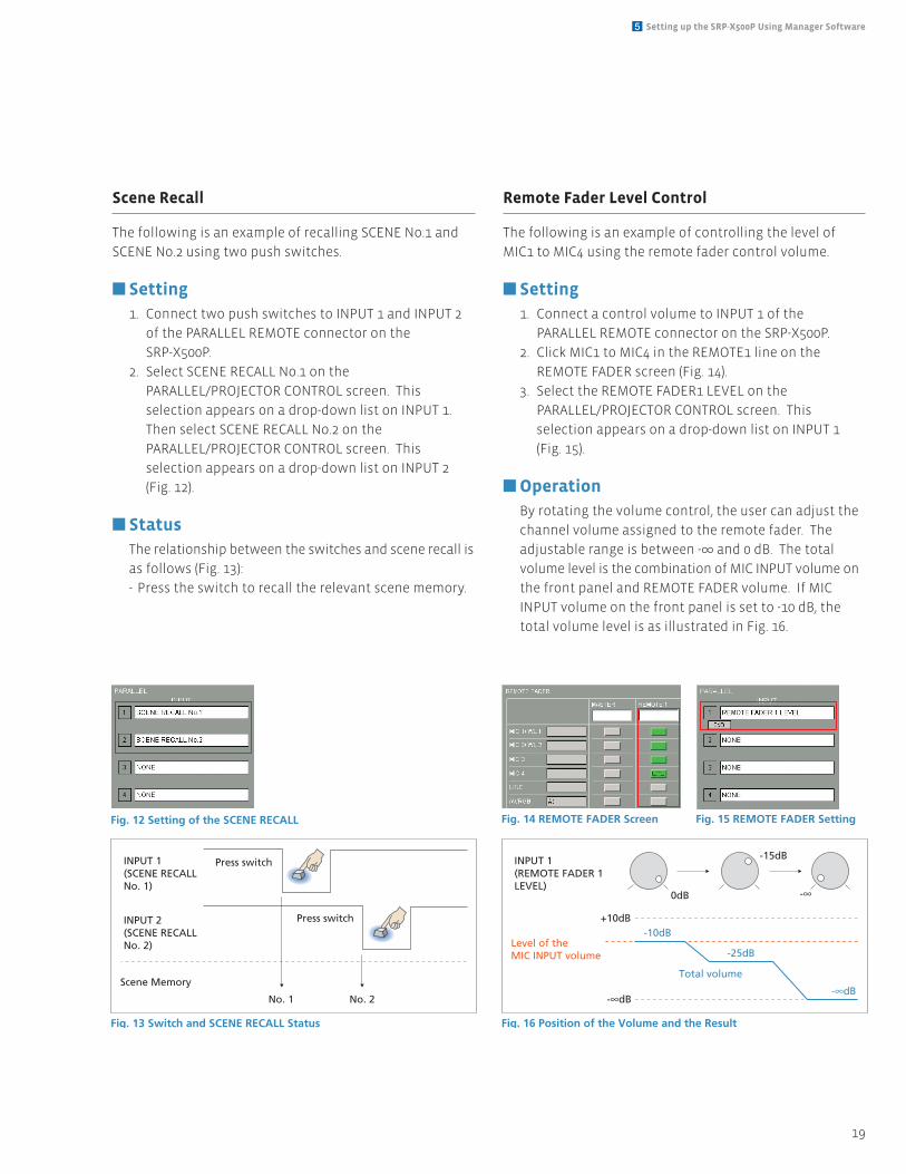
Scene Recall
The following is an example of recalling SCENE No.1 and
SCENE No.2 using two push switches.
n Setting1. Connect two push switches to INPUT 1 and INPUT 2
of the PARALLEL REMOTE connector on the
SRP-X500P.
2. Select SCENE RECALL No.1 on the
PARALLEL/PROJECTOR CONTROL screen. This
selection appears on a drop-down list on INPUT 1.
Then select SCENE RECALL No.2 on the
PARALLEL/PROJECTOR CONTROL screen. This
selection appears on a drop-down list on INPUT 2
(Fig. 12).
n StatusThe relationship between the switches and scene recall is
as follows (Fig. 13):
- Press the switch to recall the relevant scene memory.
Remote Fader Level Control
The following is an example of controlling the level of
MIC1 to MIC4 using the remote fader control volume.
n Setting1. Connect a control volume to INPUT 1 of the
PARALLEL REMOTE connector on the SRP-X500P.
2. Click MIC1 to MIC4 in the REMOTE1 line on the
REMOTE FADER screen (Fig. 14).
3. Select the REMOTE FADER1 LEVEL on the
PARALLEL/PROJECTOR CONTROL screen. This
selection appears on a drop-down list on INPUT 1
(Fig. 15).
n OperationBy rotating the volume control, the user can adjust the
channel volume assigned to the remote fader. The
adjustable range is between -∞ and 0 dB. The total
volume level is the combination of MIC INPUT volume on
the front panel and REMOTE FADER volume. If MIC
INPUT volume on the front panel is set to -10 dB, the
total volume level is as illustrated in Fig. 16.
Press switch
Press switch
No. 1 No. 2
INPUT 1(SCENE RECALLNo. 1)
INPUT 2(SCENE RECALLNo. 2)
Scene Memory
Fig. 13 Switch and SCENE RECALL Status
Fig. 12 Setting of the SCENE RECALL
Total volume
-15dB
-25dB
0dB
+10dB-10dB
-∞dB-∞dB
-∞
INPUT 1(REMOTE FADER 1LEVEL)
Level of the MIC INPUT volume
Fig. 16 Position of the Volume and the Result
Fig. 14 REMOTE FADER Screen Fig. 15 REMOTE FADER Setting
20
SRP-X500P System Integration Guide
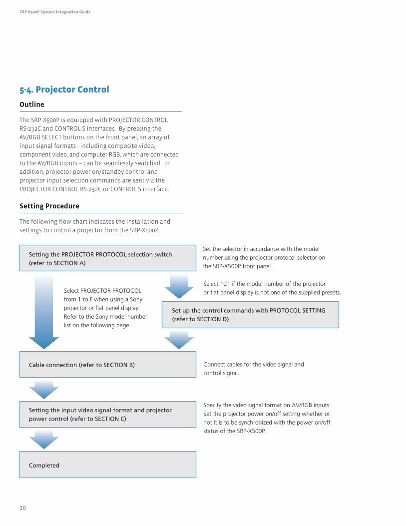
5-4. Projector Control
Outline
The SRP-X500P is equipped with PROJECTOR CONTROL
RS-232C and CONTROL S interfaces. By pressing the
AV/RGB SELECT buttons on the front panel, an array of
input signal formats - including composite video,
component video, and computer RGB, which are connected
to the AV/RGB inputs – can be seamlessly switched. In
addition, projector power on/standby control and
projector input selection commands are sent via the
PROJECTOR CONTROL RS-232C or CONTROL S interface.
Setting Procedure
The following flow chart indicates the installation and
settings to control a projector from the SRP-X500P.
Completed
Setting the input video signal format and projector power control (refer to SECTION C)
Cable connection (refer to SECTION B)
Set up the control commands with PROTOCOL SETTING (refer to SECTION D)
Setting the PROJECTOR PROTOCOL selection switch (refer to SECTION A)
Specify the video signal format on AV/RGB inputs.
Set the projector power on/off setting whether or
not it is to be synchronized with the power on/off
status of the SRP-X500P.
Connect cables for the video signal and
control signal.
Select PROJECTOR PROTOCOL
from 1 to F when using a Sony
projector or flat panel display.
Refer to the Sony model number
list on the following page.
Select "0" if the model number of the projector
or flat panel display is not one of the supplied presets.
Set the selector in accordance with the model
number using the projector protocol selector on
the SRP-X500P front panel.
21
5 Setting up the SRP-X500P Using Manager Software
SECTION A: PROJECTOR PROTOCOL SelectSwitch Setting
From the switch on the front panel, set the PROJECTORPROTOCOL selector in accordance with the product model.The following table indicates the setting for each model ofSony projector or flat panel display. This setting takeseffect after power is turned off and on.
When using a Sony projector or flat panel displayThe SRP-X500P selects the projector protocol to control aprojector or flat panel display. By selecting the presetswitch, the following projectors and flat panel displays canbe controlled from the SRP-X500P (effective as of October2006).
When using a projector or flat panel displaymanufactured by another companyIf the projector or flat panel display is not made by Sony, ornot included in the above table, set the PROJECTORPROTOCOL selector to 0 and use the SRP-X500P Managersoftware to make settings. For more details, refer toSECTION D: Projector Control Using the Protocol SettingFunction.
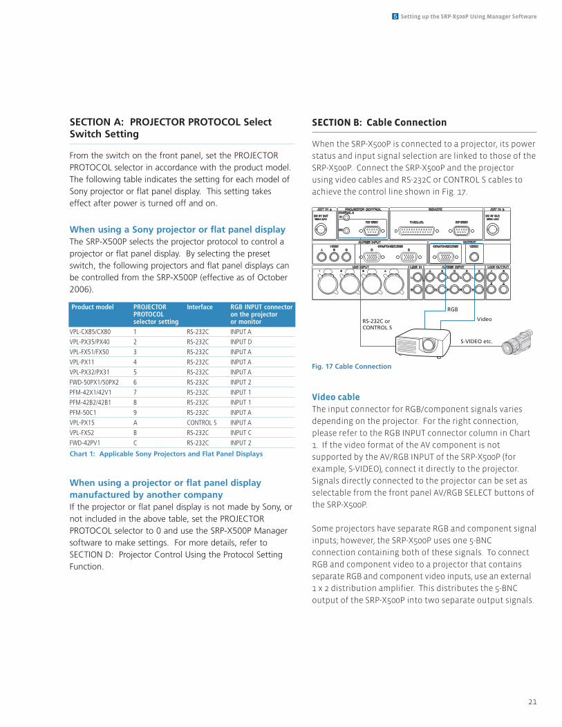
SECTION B: Cable Connection
When the SRP-X500P is connected to a projector, its power
status and input signal selection are linked to those of the
SRP-X500P. Connect the SRP-X500P and the projector
using video cables and RS-232C or CONTROL S cables to
achieve the control line shown in Fig. 17.
Video cableThe input connector for RGB/component signals varies
depending on the projector. For the right connection,
please refer to the RGB INPUT connector column in Chart
1. If the video format of the AV component is not
supported by the AV/RGB INPUT of the SRP-X500P (for
example, S-VIDEO), connect it directly to the projector.
Signals directly connected to the projector can be set as
selectable from the front panel AV/RGB SELECT buttons of
the SRP-X500P.
Some projectors have separate RGB and component signal
inputs; however, the SRP-X500P uses one 5-BNC
connection containing both of these signals. To connect
RGB and component video to a projector that contains
separate RGB and component video inputs, use an external
1 x 2 distribution amplifier. This distributes the 5-BNC
output of the SRP-X500P into two separate output signals.
RS-232C orCONTROL S
RGB
Video
S-VIDEO etc.
Fig. 17 Cable Connection
Product model PROJECTOR Interface RGB INPUT connector PROTOCOL on the projectorselector setting or monitor
VPL-CX85/CX80 1 RS-232C INPUT A
VPL-PX35/PX40 2 RS-232C INPUT D
VPL-FX51/FX50 3 RS-232C INPUT A
VPL-PX11 4 RS-232C INPUT A
VPL-PX32/PX31 5 RS-232C INPUT A
FWD-50PX1/50PX2 6 RS-232C INPUT 2
PFM-42X1/42V1 7 RS-232C INPUT 1
PFM-42B2/42B1 8 RS-232C INPUT 1
PFM-50C1 9 RS-232C INPUT A
VPL-PX15 A CONTROL S INPUT A
VPL-FX52 B RS-232C INPUT C
FWD-42PV1 C RS-232C INPUT 2
Chart 1: Applicable Sony Projectors and Flat Panel Displays
22
SRP-X500P System Integration Guide
Control cableThe control interface also varies depending on the
projector. For correct connection, refer to the Interface
column in Chart 1.
SECTION C: Input Video Signal Format andProjector Power Setting
Use the supplied SRP-X500P Manager software to set the
video signal format connected to AV/RGB INPUT A to E. In
addition, set the projector or flat panel display power
on/standby control as required. It can be linked or not
linked to the power status of the SRP-X500P. These settings
are activated on the PARALLEL/PROJECTOR CONTROL tab.
Video format settingClick the SIGNAL DEFINE selection radio button to select
the format of the video signal which is input to each
AV/RGB INPUT A to E connector. When switching the AV
source from the AV/RGB SELECT button on the SRP-X500P,
the mixer sends a control command to switch the input
signal format on the projector or display. This command
depends on the SIGNAL DEFINE settings.
If the video format of the AV component is not supported
by the AV/RGB INPUT of the SRP-X500P (for example,
S-VIDEO), select OTHER TERMINAL. This enables signals
directly connected to the projector or flat panel display to
be set as selectable from the front panel AV selector
buttons of the SRP-X500P.
Power settingProjector power control can be set using the PROJECTOR
POWER setting.
• SYNC WITH POWER ON
Projector or flat panel display power on is interlocked
with the power switch operation of the SRP-X500P.
• SYNC WITH POWER OFF
Projector or flat panel display power standby is
interlocked with the power switch operation of the
SRP-X500P.
SECTION D: Projector Control Using the Protocol Setting Function
The SRP-X500P controls input signal selection and power
on/standby of the projector by sending the control
command to the projector’s RS-232C terminal.
The following are the minimum projector requirements:
• RS-232C terminal
• RS-232C communication protocol
• RS-232C specifications:
• Baud rate: 9600bps, 19200 bps, or 38400 bps
• Parity bit: None, Even, or Odd
• Data length: 8-bit
• Stop bit: 1-bit
• Flow control: None
Know-how of projector controlGenerally, a projector cannot receive a command via the
RS-232C terminal during warm-up/cool-down of the lamp
or while detecting the sync signal of input video. The user
must wait to complete each process in sequence: power
on, select the input connector, and projection.
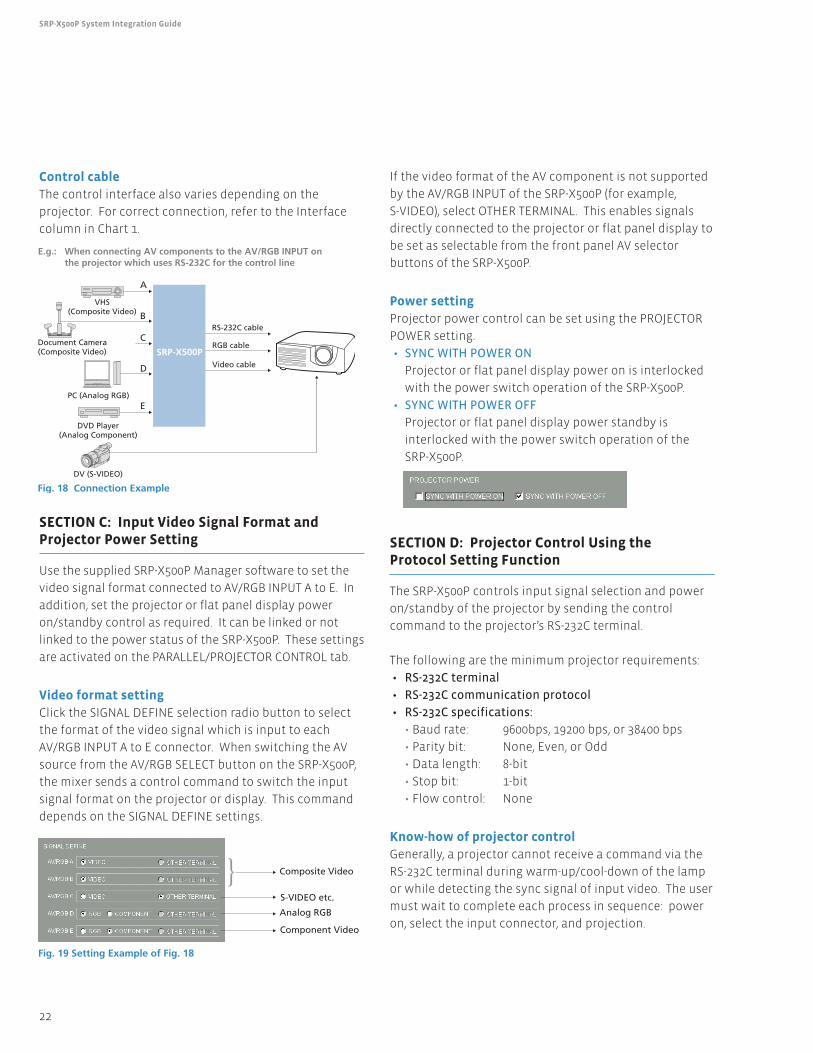
VHS(Composite Video)
DV (S-VIDEO)
Document Camera(Composite Video)
PC (Analog RGB)
DVD Player(Analog Component)
SRP-X500P
Fig. 18 Connection Example
Video cable
RGB cable
RS-232C cable
A
E
D
C
B
E.g.: When connecting AV components to the AV/RGB INPUT on the projector which uses RS-232C for the control line
Fig. 19 Setting Example of Fig. 18
Composite Video
S-VIDEO etc.
Analog RGB
Component Video
23
5 Setting up the SRP-X500P Using Manager Software
With the SRP-X500P, sending a control command and
waiting for the process on the projector are control
sequences. By combining multiple control sequences, the
SRP-X500P controls the projector power on/standby and
input signal selection.
Protocol settingThe following describes how to control a projector using
the protocol setting function of the supplied SRP-X500P
Manager software. We use the Sony VPL-FX52 Data
Projector as an example.
1. Select the PARALLEL/PROJECTOR CONTROL tab on the
SRP-X500P Manager software.
2. Click the PROTOCOL SETTING button to display the
following screen.
3. Enter commands in Hex format. Convert ASCII
command values to Hex equivalent values using the
supplied conversion table (see appendix).
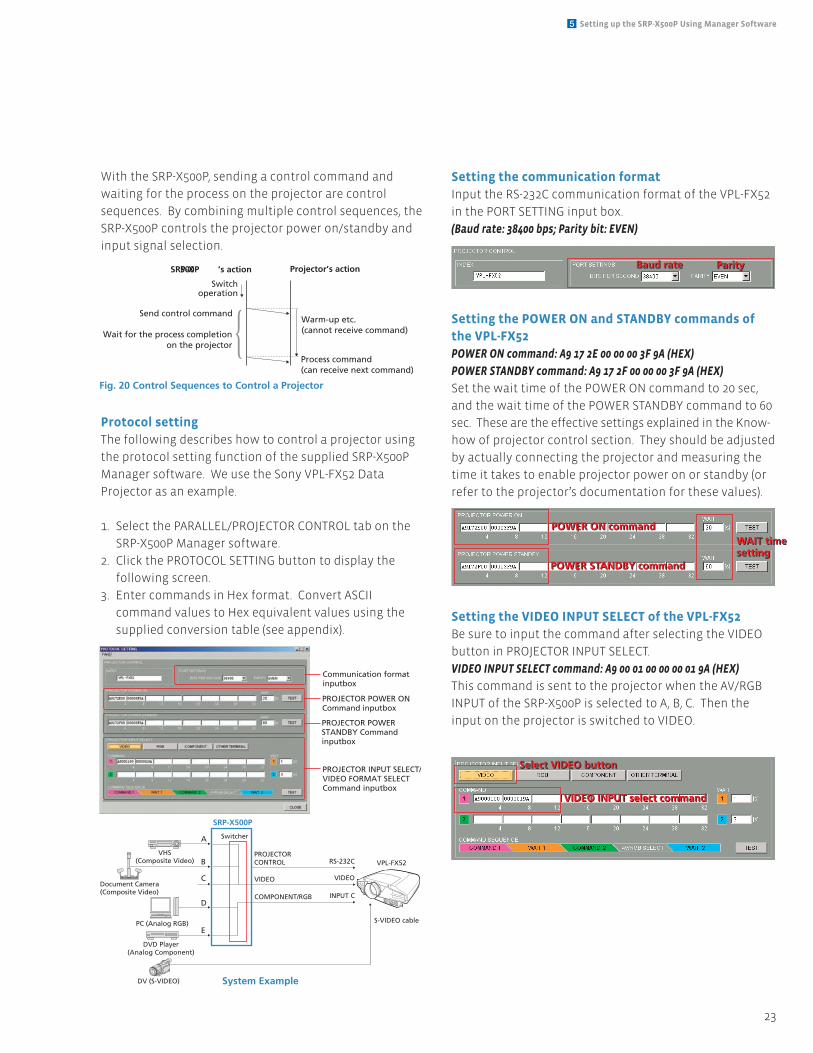
Setting the communication formatInput the RS-232C communication format of the VPL-FX52
in the PORT SETTING input box.
(Baud rate: 38400 bps; Parity bit: EVEN)
Setting the POWER ON and STANDBY commands ofthe VPL-FX52POWER ON command: A9 17 2E 00 00 00 3F 9A (HEX)
POWER STANDBY command: A9 17 2F 00 00 00 3F 9A (HEX)
Set the wait time of the POWER ON command to 20 sec,
and the wait time of the POWER STANDBY command to 60
sec. These are the effective settings explained in the Know-
how of projector control section. They should be adjusted
by actually connecting the projector and measuring the
time it takes to enable projector power on or standby (or
refer to the projector’s documentation for these values).
Setting the VIDEO INPUT SELECT of the VPL-FX52Be sure to input the command after selecting the VIDEO
button in PROJECTOR INPUT SELECT.
VIDEO INPUT SELECT command: A9 00 01 00 00 00 01 9A (HEX)
This command is sent to the projector when the AV/RGB
INPUT of the SRP-X500P is selected to A, B, C. Then the
input on the projector is switched to VIDEO.
Fig. 20 Control Sequences to Control a Projector
SRP-X500P ’s action
Switchoperation
Send control command
Wait for the process completionon the projector
Projector’s action
Warm-up etc.(cannot receive command)
Process command(can receive next command)
Baud rate
P
Parity
W
Baud rate
P
Parity
W
POWER ON command
POWER STANDBY command
V
WAIT time setting
B
POWER ON command
POWER STANDBY command
V
WAIT time setting
VIDEO INPUT select command
V
Select VIDEO button
S
VIDEO INPUT select command
V
Select VIDEO button
S
VHS(Composite Video)
DV (S-VIDEO)
Document Camera(Composite Video)
PROJECTOR POWER ONCommand inputbox
Communication formatinputbox
PROJECTOR POWERSTANDBY Command inputbox
PROJECTOR INPUT SELECT/VIDEO FORMAT SELECTCommand inputbox
PC (Analog RGB)
DVD Player(Analog Component)
SRP-X500P
System Example
INPUT C
VIDEO
RS-232C
COMPONENT/RGB
VIDEO
PROJECTOR CONTROL VPL-FX52
S-VIDEO cable
SwitcherA
E
D
C
B
24
SRP-X500P System Integration Guide
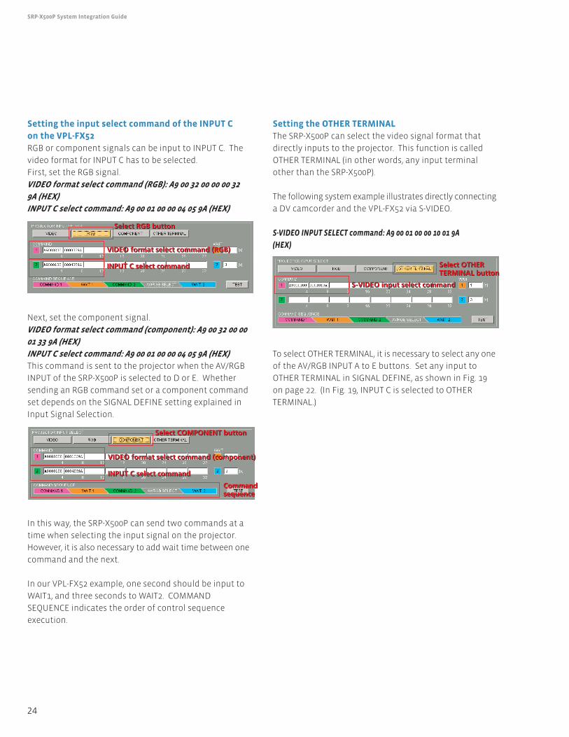
Setting the input select command of the INPUT C on the VPL-FX52RGB or component signals can be input to INPUT C. The
video format for INPUT C has to be selected.
First, set the RGB signal.
VIDEO format select command (RGB): A9 00 32 00 00 00 32
9A (HEX)
INPUT C select command: A9 00 01 00 00 04 05 9A (HEX)
Next, set the component signal.
VIDEO format select command (component): A9 00 32 00 00
01 33 9A (HEX)
INPUT C select command: A9 00 01 00 00 04 05 9A (HEX)
This command is sent to the projector when the AV/RGB
INPUT of the SRP-X500P is selected to D or E. Whether
sending an RGB command set or a component command
set depends on the SIGNAL DEFINE setting explained in
Input Signal Selection.
In this way, the SRP-X500P can send two commands at a
time when selecting the input signal on the projector.
However, it is also necessary to add wait time between one
command and the next.
In our VPL-FX52 example, one second should be input to
WAIT1, and three seconds to WAIT2. COMMAND
SEQUENCE indicates the order of control sequence
execution.
Setting the OTHER TERMINALThe SRP-X500P can select the video signal format that
directly inputs to the projector. This function is called
OTHER TERMINAL (in other words, any input terminal
other than the SRP-X500P).
The following system example illustrates directly connecting
a DV camcorder and the VPL-FX52 via S-VIDEO.
S-VIDEO INPUT SELECT command: A9 00 01 00 00 10 01 9A
(HEX)
To select OTHER TERMINAL, it is necessary to select any one
of the AV/RGB INPUT A to E buttons. Set any input to
OTHER TERMINAL in SIGNAL DEFINE, as shown in Fig. 19
on page 22. (In Fig. 19, INPUT C is selected to OTHER
TERMINAL.)
VIDEO format select command (RGB)
INPUT C select command
V
Select RGB button
S
VIDEO format select command (RGB)
INPUT C select command
V
Select RGB button
S
VIDEO format select command (component)
INPUT C select command
S
Commandsequence
S
Select COMPONENT button
S
VIDEO format select command (component)
INPUT C select command
S
Commandsequence
S
Select COMPONENT button
S
S-VIDEO input select command
C
Select OTHER TERMINAL button
P
S-VIDEO input select command
C
Select OTHER TERMINAL button
P
25
6 Appendix
Feedback
What is feedback (howling)?Feedback in a sound system incorporating microphones and
speakers is the ringing or screeching noise you occasionally
hear. This phenomenon is often called “howling.”
Mechanism of howlingIn a sound system, the microphone signal is amplified and
output from a loudspeaker. However, the output signal is
sometimes picked up by the microphone again, and loops
around the microphone, amplifier, and speaker. If the loop
gain reaches one time or more, the signal is limitlessly
amplified. This is when howling occurs.
Frequency response between microphones andspeakersControlling the frequency response between microphones
and speakers is the key to suppressing howling. The
response varies depending on the width of the room, the
materials of the wall and ceiling, and the speaker location.
Feedback reductionThe feedback reduction incorporated in the SRP-X500P
scans the audio spectrum each time the button is held
down (for two seconds or more) to detect the howling
frequency points and suppress the level of the detected
frequency bands. This process is performed independently
for each microphone input. If you change the type or
location of a microphone, feedback reduction should be
activated again in order to optimize the amount of
feedback reduction.
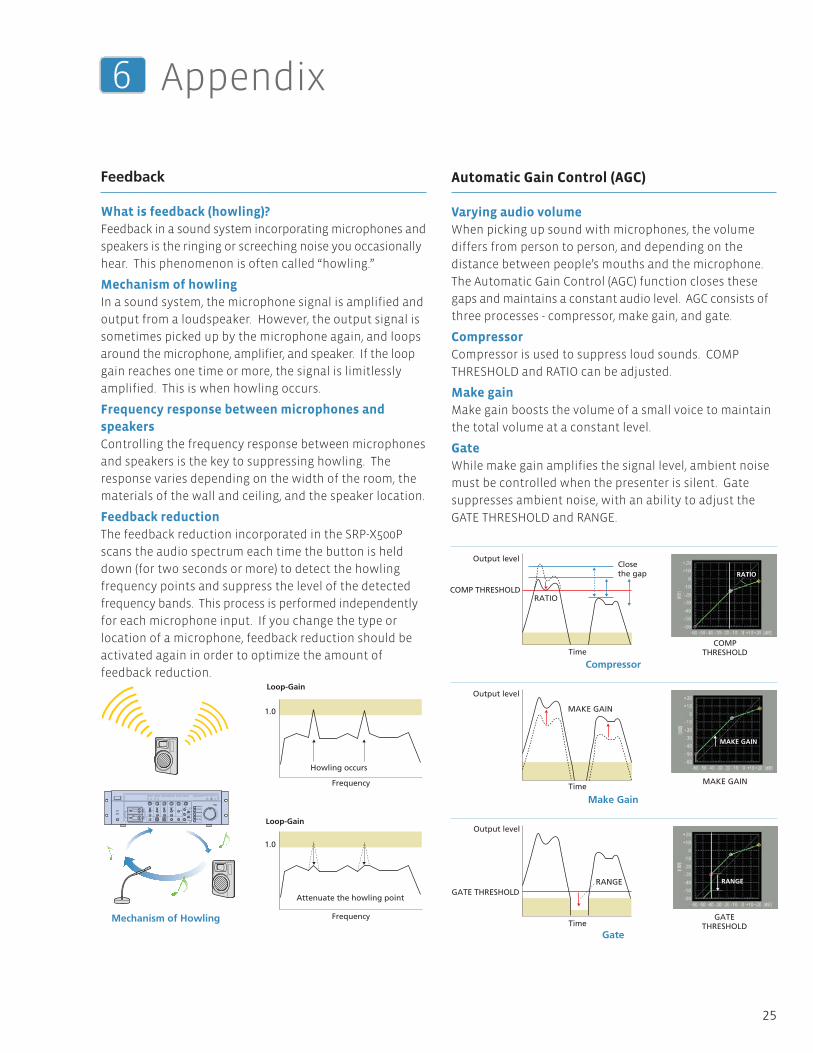
Automatic Gain Control (AGC)
Varying audio volumeWhen picking up sound with microphones, the volume
differs from person to person, and depending on the
distance between people’s mouths and the microphone.
The Automatic Gain Control (AGC) function closes these
gaps and maintains a constant audio level. AGC consists of
three processes - compressor, make gain, and gate.
CompressorCompressor is used to suppress loud sounds. COMP
THRESHOLD and RATIO can be adjusted.
Make gainMake gain boosts the volume of a small voice to maintain
the total volume at a constant level.
GateWhile make gain amplifies the signal level, ambient noise
must be controlled when the presenter is silent. Gate
suppresses ambient noise, with an ability to adjust the
GATE THRESHOLD and RANGE.
Loop-Gain
Loop-Gain
1.0
1.0
Howling occurs
Frequency
Frequency
Attenuate the howling point
Mechanism of Howling
Output level
COMP THRESHOLD
Output level
Output level
GATE THRESHOLD
RATIO
Close the gap
Time
Time
Time
MAKE GAIN
RANGE
R
RATIO
MAKE GAIN
RANGE
COMPTHRESHOLD
MAKE GAIN
GATETHRESHOLD
Compressor
Make Gain
Gate
26
SRP-X500P System Integration Guide
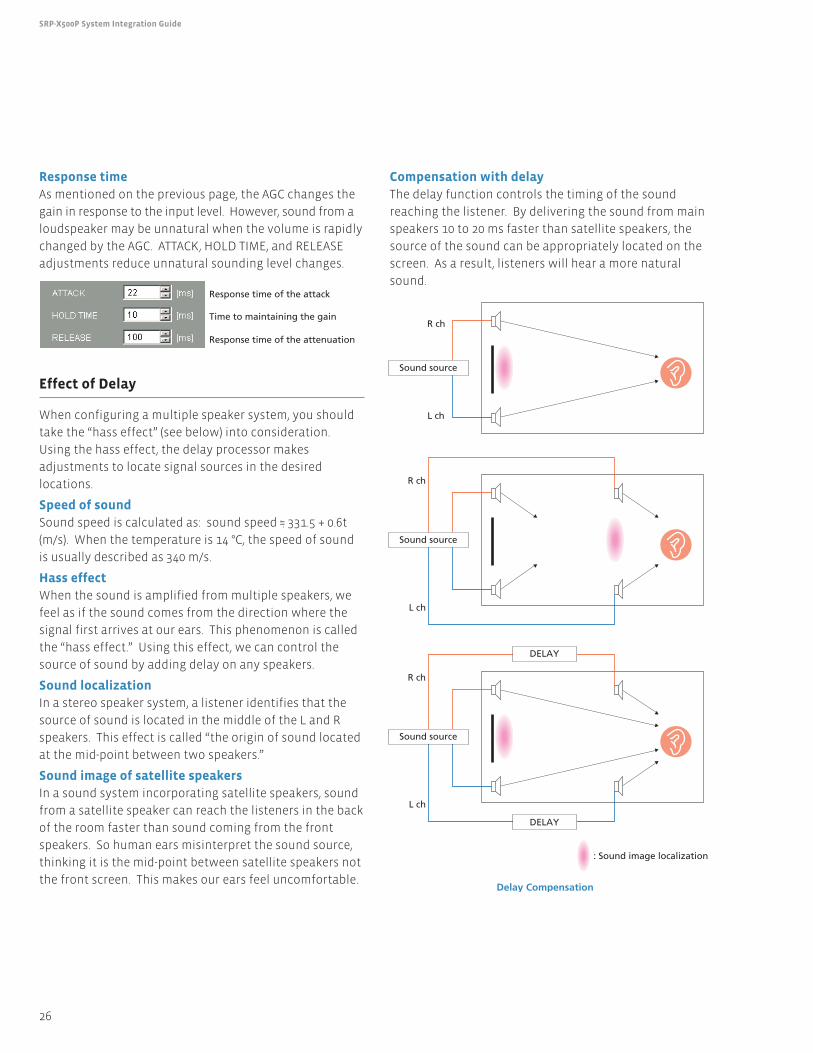
Response timeAs mentioned on the previous page, the AGC changes the
gain in response to the input level. However, sound from a
loudspeaker may be unnatural when the volume is rapidly
changed by the AGC. ATTACK, HOLD TIME, and RELEASE
adjustments reduce unnatural sounding level changes.
Effect of Delay
When configuring a multiple speaker system, you should
take the “hass effect” (see below) into consideration.
Using the hass effect, the delay processor makes
adjustments to locate signal sources in the desired
locations.
Speed of soundSound speed is calculated as: sound speed ·=· 331.5 + 0.6t
(m/s). When the temperature is 14 °C, the speed of sound
is usually described as 340 m/s.
Hass effectWhen the sound is amplified from multiple speakers, we
feel as if the sound comes from the direction where the
signal first arrives at our ears. This phenomenon is called
the “hass effect.” Using this effect, we can control the
source of sound by adding delay on any speakers.
Sound localizationIn a stereo speaker system, a listener identifies that the
source of sound is located in the middle of the L and R
speakers. This effect is called “the origin of sound located
at the mid-point between two speakers.”
Sound image of satellite speakersIn a sound system incorporating satellite speakers, sound
from a satellite speaker can reach the listeners in the back
of the room faster than sound coming from the front
speakers. So human ears misinterpret the sound source,
thinking it is the mid-point between satellite speakers not
the front screen. This makes our ears feel uncomfortable.
Compensation with delayThe delay function controls the timing of the sound
reaching the listener. By delivering the sound from main
speakers 10 to 20 ms faster than satellite speakers, the
source of the sound can be appropriately located on the
screen. As a result, listeners will hear a more natural
sound.
Sound source
DELAY
DELAY
L ch
R ch
: Sound image localization
Sound source
L ch
R ch
Sound source
L ch
R ch
Delay Compensation
Response time of the attack
Response time of the attenuation
Time to maintaining the gain
R
27
6 Appendix
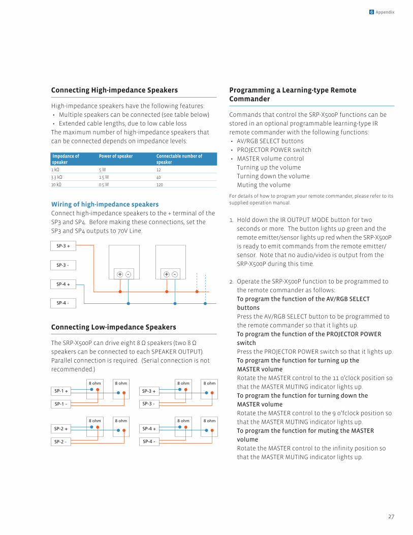
Connecting High-impedance Speakers
High-impedance speakers have the following features:
• Multiple speakers can be connected (see table below)
• Extended cable lengths, due to low cable loss
The maximum number of high-impedance speakers that
can be connected depends on impedance levels:
Wiring of high-impedance speakersConnect high-impedance speakers to the + terminal of the
SP3 and SP4. Before making these connections, set the
SP3 and SP4 outputs to 70V Line.
Connecting Low-impedance Speakers
The SRP-X500P can drive eight 8 Ω speakers (two 8 Ω
speakers can be connected to each SPEAKER OUTPUT).
Parallel connection is required. (Serial connection is not
recommended.)
Programming a Learning-type RemoteCommander
Commands that control the SRP-X500P functions can be
stored in an optional programmable learning-type IR
remote commander with the following functions:
• AV/RGB SELECT buttons
• PROJECTOR POWER switch
• MASTER volume control
Turning up the volume
Turning down the volume
Muting the volume
For details of how to program your remote commander, please refer to its
supplied operation manual.
1. Hold down the IR OUTPUT MODE button for two
seconds or more. The button lights up green and the
remote emitter/sensor lights up red when the SRP-X500P
is ready to emit commands from the remote emitter/
sensor. Note that no audio/video is output from the
SRP-X500P during this time.
2. Operate the SRP-X500P function to be programmed to
the remote commander as follows:
To program the function of the AV/RGB SELECT
buttons
Press the AV/RGB SELECT button to be programmed to
the remote commander so that it lights up.
To program the function of the PROJECTOR POWER
switch
Press the PROJECTOR POWER switch so that it lights up.
To program the function for turning up the
MASTER volume
Rotate the MASTER control to the 11 o’clock position so
that the MASTER MUTING indicator lights up.
To program the function for turning down the
MASTER volume
Rotate the MASTER control to the 9 o’fclock position so
that the MASTER MUTING indicator lights up.
To program the function for muting the MASTER
volume
Rotate the MASTER control to the infinity position so
that the MASTER MUTING indicator lights up.
SP-3 +
SP-3 -
SP-4 +
SP-4 -
S
+ - + -
SP-1 +
SP-1 -
SP-2 +
SP-2 -
SP-3 +
SP-3 -
SP-4 +
SP-4 -
8 ohm 8 ohm
8 ohm 8 ohm
8 ohm 8 ohm
8 ohm 8 ohm
+
Impedance of Power of speaker Connectable number of speaker speaker
1 kΩ 5 W 12
3.3 kΩ 1.5 W 40
10 kΩ 0.5 W 120
28
SRP-X500P System Integration Guide
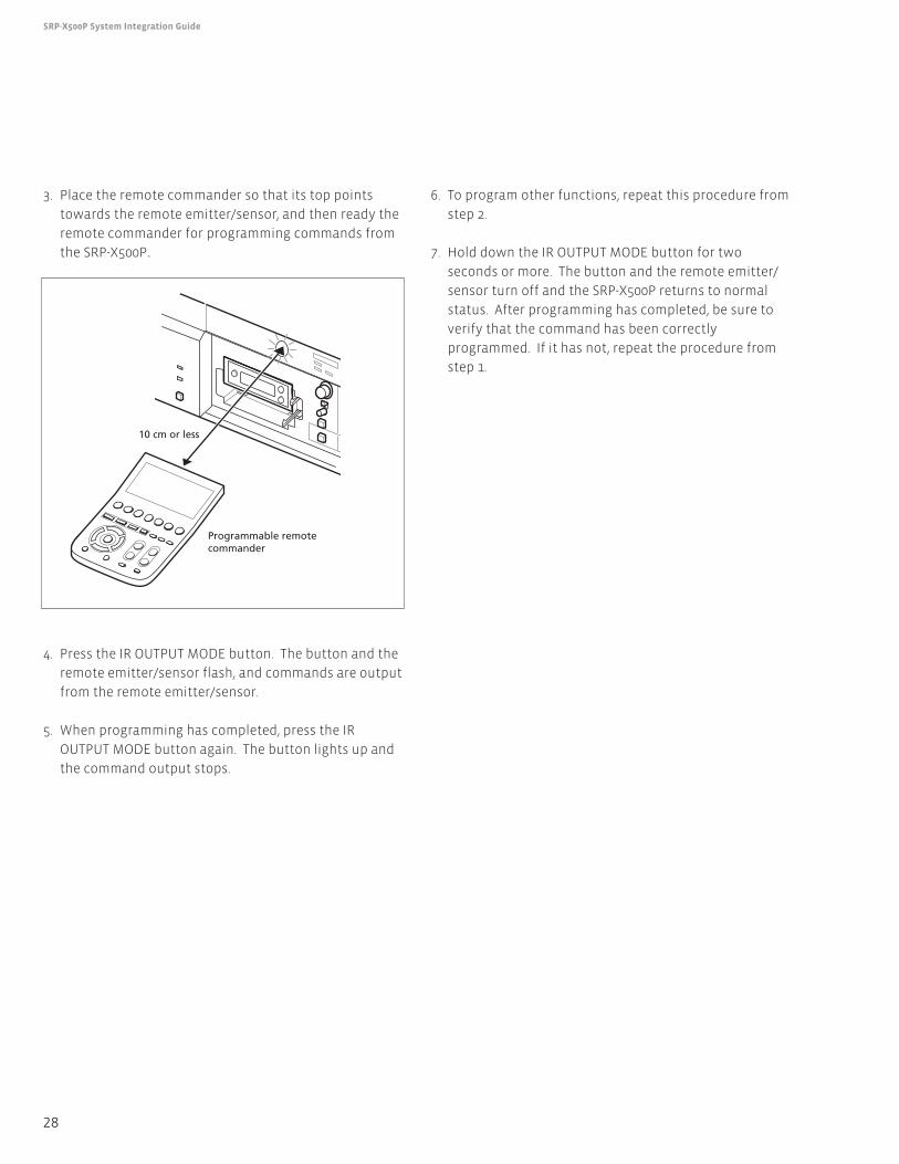
3. Place the remote commander so that its top points
towards the remote emitter/sensor, and then ready the
remote commander for programming commands from
the SRP-X500P.
4. Press the IR OUTPUT MODE button. The button and the
remote emitter/sensor flash, and commands are output
from the remote emitter/sensor.
5. When programming has completed, press the IR
OUTPUT MODE button again. The button lights up and
the command output stops.
6. To program other functions, repeat this procedure from
step 2.
7. Hold down the IR OUTPUT MODE button for two
seconds or more. The button and the remote emitter/
sensor turn off and the SRP-X500P returns to normal
status. After programming has completed, be sure to
verify that the command has been correctly
programmed. If it has not, repeat the procedure from
step 1.
Programmable remote commander
10 cm or less
ANT IN
SPEAKER
OUTPUT 1
SPEAKER
OUTPUT 2
SPEAKER
OUTPUT 3
SPEAKER
OUTPUT 4
LINE
OUTPUT 1
LINE
OUTPUT 2
LINE
OUTPUT 3
LINE
OUTPUT 4
+48V
RF
TRIM
SIGNALVUMETER
MUTING
MUTING
AGC
SPEAKEROUTPUT
BUSROUTING
LINEOUTPUT
BUSROUTING
MIC MIX
BUS
INPUTLEVEL
MUTING VU METER
VU METER
SPEAKER OUT
SPEAKER OUT
CH1/2
CH3/4 70V LINE
CLIP
DIGITAL PROTECTION
EMGPOWER
AMP
CLIPLCF/BTL
Lo Imp.
70V LINE
OUTPUTLEVEL MUTING
MUTING
OUTPUTLEVEL MUTING
MUTINGOUTPUTLEVEL MUTING
MUTINGOUTPUTLEVEL MUTING
MUTINGOUTPUTLEVEL MUTING
EQ COMP DELAY
MUTINGOUTPUTLEVEL MUTING
MUTINGOUTPUTLEVEL MUTING
MUTINGOUTPUTLEVEL MUTING
LCF FR/EQ
REF.
AFMIC
INPUT 1
WL
+48V
RF
TRIM
SIGNALVUMETER
MUTING
MUTING
INPUTLEVEL
LCF FR/EQ
REF.
AFMIC
INPUT 2
WL
TUNER 2
+48V TRIM
SIGNALVUMETER MUTING
MUTING
INPUTLEVEL
LCF FR/EQ
REF.
MIC
INPUT 3
+48V TRIM
TRIM
TRIM
TRIM
TRIM
TRIM
TRIM
SIGNALVUMETER
VUMETER
MUTING
MUTINGINPUTLEVEL
MUTING
MUTINGINPUTLEVEL
LCF FR/EQ
REF.
SIGNAL
REF.
VUMETER
AUDIOSELECTOR
VIDEOSELECTOR
RGBSELECTOR
MUTING
MUTING
INPUT INPUT
VOLUMEFADER(GUI)
FADER(GUI)
INPUT
FADER(GUI)
REMOTE
OUTPUT
FADER(GUI)
REMOTE
INPUT LEVEL
OUTPUT LEVEL
LEVEL
OUTPUT
LEVEL
INPUTLEVEL
SIGNAL
REF.
VIDEO
OUTPUT
COMPONENT/RGB
OUTPUT
MIC
INPUT 4
LINE
INPUT
INPUT
A
B
C
A
B
C
D
E
A
BC
D
E
D
E
AV/RGB
INPUTVIDEO
INPUT
COMPONENT/RGB
TUNER 1
PROJECTOR PROTOCOL
PROJECTOR
REMOTE
CONTROL
RS-232C
RS-232C
INPUT
OUTPUT
CONTROL S
RERALLEL
IR OUT
(CONTROLS)
(CONTROLS)
IR IN
PROJECTOR POWER
AV/RGB SELECT
IR OUTPUT MODE
MAIN CPURS-232C
29
6 Appendix
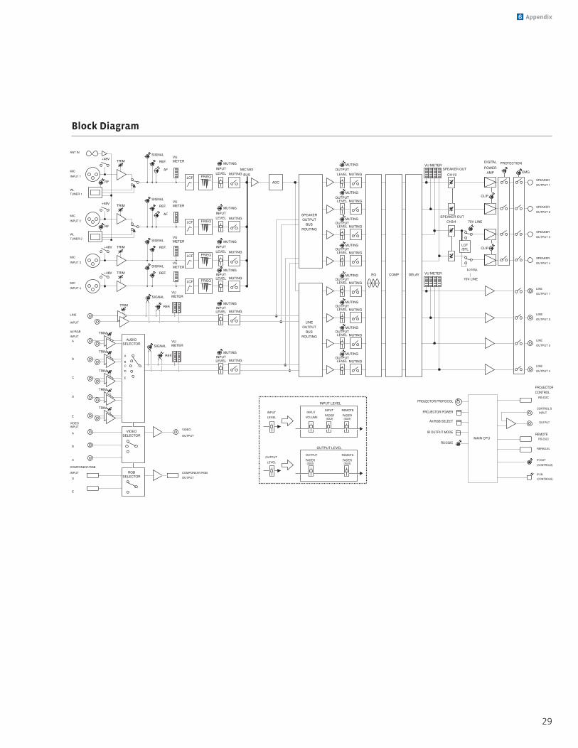
Block Diagram
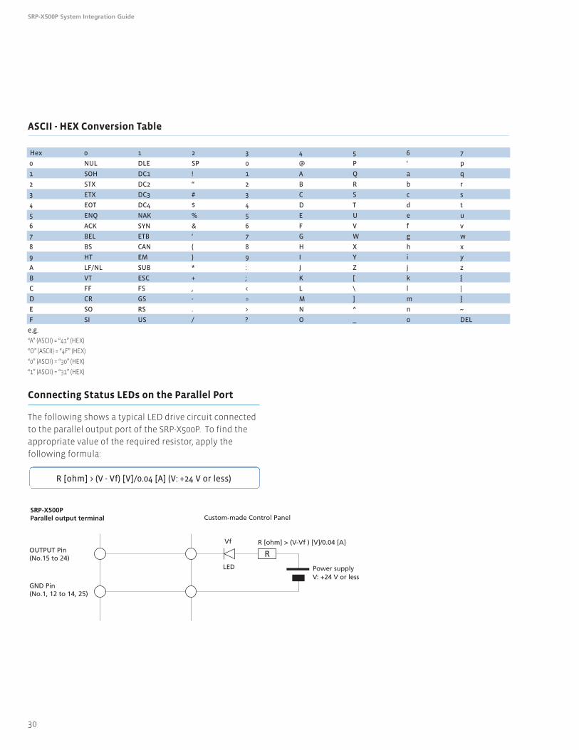
ASCII - HEX Conversion Table
30
SRP-X500P System Integration Guide
Connecting Status LEDs on the Parallel Port
The following shows a typical LED drive circuit connected
to the parallel output port of the SRP-X500P. To find the
appropriate value of the required resistor, apply the
following formula:
R [ohm] > (V - Vf) [V]/0.04 [A] (V: +24 V or less)
SRP-X500PParallel output terminal
OUTPUT Pin(No.15 to 24)
GND Pin(No.1, 12 to 14, 25)
Custom-made Control Panel
Vf R [ohm] > (V-Vf ) [V]/0.04 [A]
LED Power supplyV: +24 V or less
R
Hex 0 1 2 3 4 5 6 7
0 NUL DLE SP 0 @ P ‘ p
1 SOH DC1 ! 1 A Q a q
2 STX DC2 “ 2 B R b r
3 ETX DC3 # 3 C S c s
4 EOT DC4 $ 4 D T d t
5 ENQ NAK % 5 E U e u
6 ACK SYN & 6 F V f v
7 BEL ETB ‘ 7 G W g w
8 BS CAN ( 8 H X h x
9 HT EM ) 9 I Y i y
A LF/NL SUB * : J Z j z
B VT ESC + ; K [ k
C FF FS , < L \ l |
D CR GS - = M ] m
E SO RS . > N ^ n ~
F SI US / ? O _ o DEL
e.g.
“A” (ASCII) = “41” (HEX)
“O” (ASCII) = “4F” (HEX)
“0” (ASCII) = “30” (HEX)
“1” (ASCII) = “31” (HEX)
31
6 Appendix
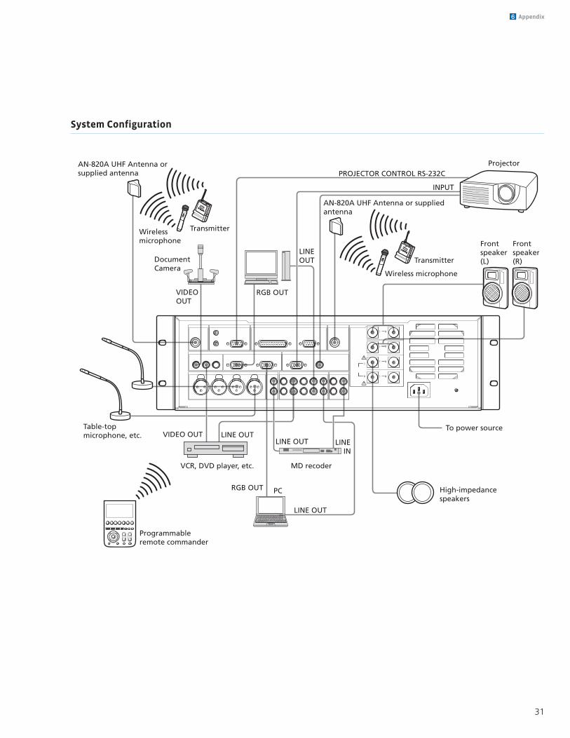
System Configuration
3 #
3 #
3 #3
# 3 #
VIDEOOUT
RGB OUT
PC
LINE OUT
PROJECTOR CONTROL RS-232C
INPUT
VIDEO OUT LINE OUTLINE OUT LINE
IN
RGB OUT
LINE OUT
To power source
High-impedance speakers
AN-820A UHF Antenna orsupplied antenna
AN-820A UHF Antenna or supplied antenna
TransmitterWirelessmicrophone
Transmitter
Wireless microphone
Table-topmicrophone, etc.
Programmableremote commander
Frontspeaker(L)
Frontspeaker(R)
Projector
DocumentCamera
VCR, DVD player, etc. MD recoder
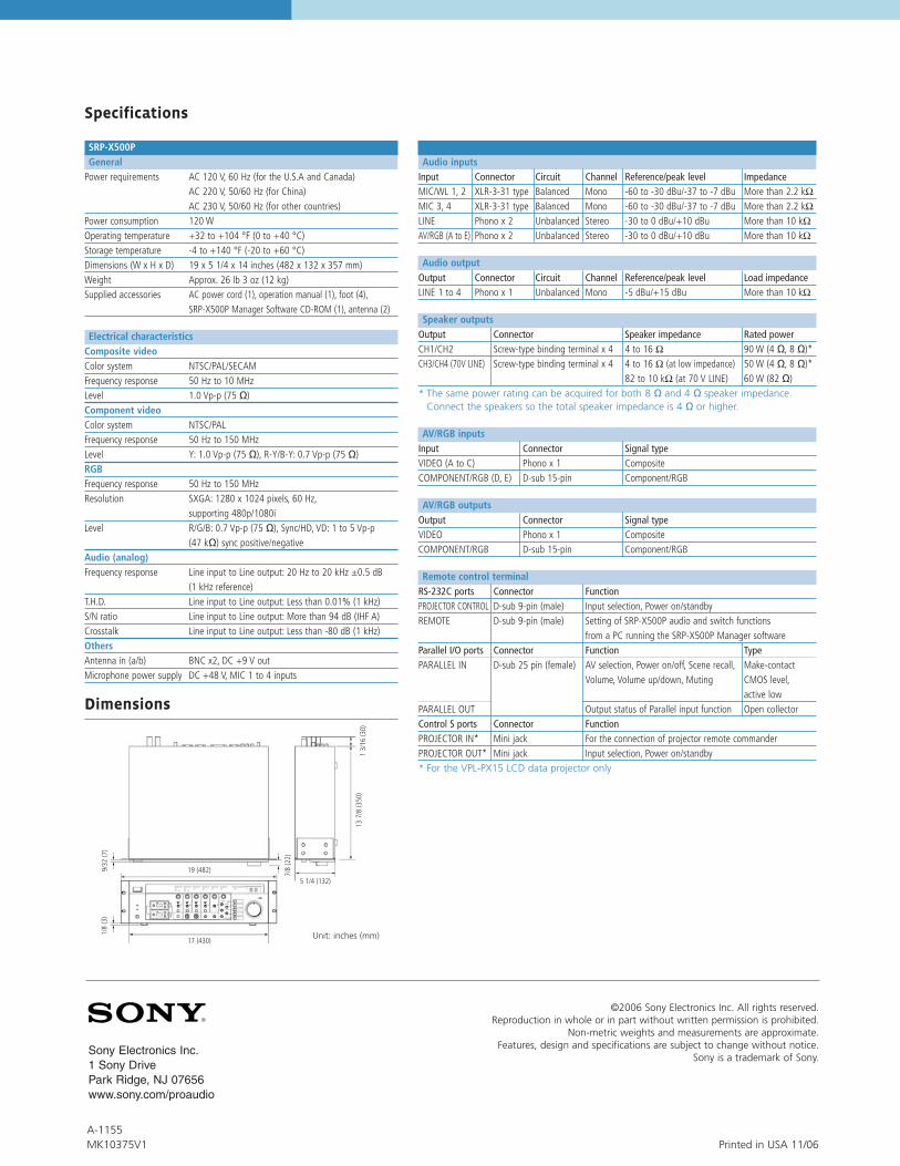
Specifications
SRP-X500PGeneral
Power requirements AC 120 V, 60 Hz (for the U.S.A and Canada)AC 220 V, 50/60 Hz (for China)AC 230 V, 50/60 Hz (for other countries)
Power consumption 120 WOperating temperature +32 to +104 °F (0 to +40 °C)Storage temperature -4 to +140 °F (-20 to +60 °C)Dimensions (W x H x D) 19 x 5 1/4 x 14 inches (482 x 132 x 357 mm)Weight Approx. 26 lb 3 oz (12 kg)Supplied accessories AC power cord (1), operation manual (1), foot (4),
SRP-X500P Manager Software CD-ROM (1), antenna (2)
Electrical characteristicsComposite videoColor system NTSC/PAL/SECAMFrequency response 50 Hz to 10 MHzLevel 1.0 Vp-p (75 Ω)Component videoColor system NTSC/PALFrequency response 50 Hz to 150 MHzLevel Y: 1.0 Vp-p (75 Ω), R-Y/B-Y: 0.7 Vp-p (75 Ω)RGBFrequency response 50 Hz to 150 MHzResolution SXGA: 1280 x 1024 pixels, 60 Hz,
supporting 480p/1080iLevel R/G/B: 0.7 Vp-p (75 Ω), Sync/HD, VD: 1 to 5 Vp-p
(47 kΩ) sync positive/negativeAudio (analog)Frequency response Line input to Line output: 20 Hz to 20 kHz ±0.5 dB
(1 kHz reference)T.H.D. Line input to Line output: Less than 0.01% (1 kHz)S/N ratio Line input to Line output: More than 94 dB (IHF A)Crosstalk Line input to Line output: Less than -80 dB (1 kHz)OthersAntenna in (a/b) BNC x2, DC +9 V outMicrophone power supply DC +48 V, MIC 1 to 4 inputs
Audio inputsInput Connector Circuit Channel Reference/peak level ImpedanceMIC/WL 1, 2 XLR-3-31 type Balanced Mono -60 to -30 dBu/-37 to -7 dBu More than 2.2 kΩMIC 3, 4 XLR-3-31 type Balanced Mono -60 to -30 dBu/-37 to -7 dBu More than 2.2 kΩLINE Phono x 2 Unbalanced Stereo -30 to 0 dBu/+10 dBu More than 10 kΩAV/RGB (A to E) Phono x 2 Unbalanced Stereo -30 to 0 dBu/+10 dBu More than 10 kΩ
Audio outputOutput Connector Circuit Channel Reference/peak level Load impedanceLINE 1 to 4 Phono x 1 Unbalanced Mono -5 dBu/+15 dBu More than 10 kΩ
Speaker outputsOutput Connector Speaker impedance Rated powerCH1/CH2 Screw-type binding terminal x 4 4 to 16 Ω 90 W (4 Ω, 8 Ω)*CH3/CH4 (70V LINE) Screw-type binding terminal x 4 4 to 16 Ω (at low impedance) 50 W (4 Ω, 8 Ω)*
82 to 10 kΩ (at 70 V LINE) 60 W (82 Ω)* The same power rating can be acquired for both 8 Ω and 4 Ω speaker impedance.
Connect the speakers so the total speaker impedance is 4 Ω or higher.
AV/RGB inputsInput Connector Signal typeVIDEO (A to C) Phono x 1 CompositeCOMPONENT/RGB (D, E) D-sub 15-pin Component/RGB
AV/RGB outputsOutput Connector Signal typeVIDEO Phono x 1 CompositeCOMPONENT/RGB D-sub 15-pin Component/RGB
Remote control terminalRS-232C ports Connector FunctionPROJECTOR CONTROL D-sub 9-pin (male) Input selection, Power on/standbyREMOTE D-sub 9-pin (male) Setting of SRP-X500P audio and switch functions
from a PC running the SRP-X500P Manager softwareParallel I/O ports Connector Function TypePARALLEL IN D-sub 25 pin (female) AV selection, Power on/off, Scene recall, Make-contact
Volume, Volume up/down, Muting CMOS level,active low
PARALLEL OUT Output status of Parallel input function Open collectorControl S ports Connector FunctionPROJECTOR IN* Mini jack For the connection of projector remote commanderPROJECTOR OUT* Mini jack Input selection, Power on/standby* For the VPL-PX15 LCD data projector only
482 (19)
430 (17)
132 (5 1/4)
22(7
/8)
30(1
3/16
)
3(1
/8)
350
(13
7/8)
7(9
/32)
Dimensions
Unit: inches (mm)
©2006 Sony Electronics Inc. All rights reserved.Reproduction in whole or in part without written permission is prohibited.
Non-metric weights and measurements are approximate.Features, design and specifications are subject to change without notice.
Sony is a trademark of Sony.Sony Electronics Inc.1 Sony DrivePark Ridge, NJ 07656www.sony.com/proaudio
Printed in USA 11/06A-1155MK10375V1
9/32
(7)
1/8
(3)
137/
8(3
50)
13/
16(3
0)
7/8
(22)
5 1/4 (132)
17 (430)
19 (482)