
SPECIALIZED METAL PRODUCT CATALOG
56
ISO 9001:2008 Certified 800.711.4939 • directmetals.com WIRE PERFORATED SAFETY EXPANDED BAR FIBERGLASS MESH METAL GRATING METAL GRATING GRATING CATALOG SPECIALIZED METAL PRODUCTS
Transcript of SPECIALIZED METAL PRODUCT CATALOG
ISO 9001:2008 Certified
800.711.4939 • directmetals.com
wire perforated safety expanded bar fiberglass mesh metal grating metal grating grating
CATALOG
SPECIALIZED METAL PRODUCTS

Types of Perforations ................................................... 12Available Tooling with Open Area % ....................... 13-14Rounds ......................................................................... 15Formula & Applications................................................. 16
PERFORATED METAL
Grip Strut - Regular .................................................... 1-4Grip Strut - Walkway ..................................................... 5Grip Strut - Heavy Duty .............................................. 5-7Traction Tread - Sheets, Planks & Ladder Rungs ........ 8Grip Strut - Stair Treads ................................................ 9Grate-Lock................................................................... 10Perf-O Grip .................................................................. 11
SAFETY GRATING
Glossary & Terminology ............................................... 17Aluminum Products ................................................. 18-21TiteWeld® ..................................................................... 22Other Welded Grating.............................................. 23-29Stair Treads ................................................................. 30Anchoring Devices ....................................................... 31
BAR GRATING
Applications ................................................................. 32Grating Products........................................................... 33Resin Systems & Molded Details ............................ 34-35Pultruded Features & Details................................... 36-37Pultruded T Pedestrian Series Grating Details ............. 38Molded Heavy Duty Grating Details ............................. 39Pultruded Resin Systems, Colors & Clip Assemblies ... 40
FIBERGLASS
Manufacturing Processes & Shearing .......................... 41Regular Expanded Metal & U-Edging........................... 42Flattened Expanded Metal & Grating ........................... 43Applications .................................................................. 44
EXPANDED METAL
Terminology .......................................................... ........45Stainless Steel Filters ........................................... ........46PVC Wire Mesh ............................................................ 47Wire Cloth Specifications & Standards .................... 48-52Applications .................................................................. 53
WIRE CLOTH
Direct Metals Company, LLC
CORPORATE HEADQUARTERS3775 Cobb International Blvd
Kennesaw, GA 30152-4390Phone: (770) 528-9001
Fax: (770) 528-9002
CHICAGO OFFICE3380 Grand Avenue
Waukegan, IL 60085Phone: (847) 599-0233
Fax: (847) 599-0244
Disclaimer: Information of a technical nature contained herein is intended only for evaluation by technically skilled persons, with any use thereof to be at their independent discretion and risk. Such information is reliable when evaluated in the proper manner under conditions as described herein. Direct Metals shall have no responsibility or liability for results obtained or damages resulting from improper evaluation or use.
Please note that application photos reflected are typical of our types of products in use that can be supplied or have been supplied by DIRECTMETALS. Some photos may depict uses designed, manufactured,fabricated or installed by others.
WE’LL CUT ANYTHINGIN OUR INVENTORYTO YOUR SPECS!
800.711.4939
ISO 9001:2008 Certified
“We manufacture toASTM Standards.”
Table of Contents
1800.711.4939
www.directmetals.com
SAFETY GRATING
Direct Metals — Your Safety Grating Source featuringGrip Strut®
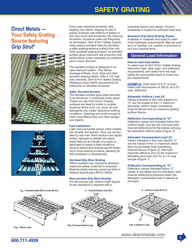
Every year industrial accidents, falls,tripping over debris, slipping on wet or greasy surfaces cost millions of dollars in lost man hours and production. By reducing accidents, insurance costs can frequently be decreased. GRIP STRUT Safety Grating helps reduce accident rates by providing a safer walking-working surface than any other available grating product. Its serrated surface gives maximum slip protection and performance under practically all conditions and in every direction.
The serrated surface is designed in an open diamond pattern. This allows drainage of fluids, mud, chips and otheraccident-causing debris. With 4-1/2" high side channels, GRIP STRUT Safety Grating Walkways meet OSHA requirements for toeboards on elevated structures.
Safer, Serrated SurfaceThe serrated surface grips soles securely in all directions, in practically every place. These non-slip GRIP STRUT Grating surfaces are ideal for inside or outside locations where mud, ice, snow, oil and detergents can create hazardous walking conditions. Openings are small enough to catch most falling tools and other danger-ous objects.
Fast InstallationLight, easy-to-handle planks make installa-tion simpler and quicker. They can be han-dled by one man. Most sections are rapidly bolted, clamped or welded into place,easily field-cut at virtually any angle orfabricated to adapt to field conditions.Several attachment devices permit fasten-ing to most existing surfaces, allowing for fast installation or disassembly.
Serrated Grip Strut GratingOffers excellent slip resistance wherever maximum safety underfoot is essential.Material meets anti-slip values set forth in Federal Specification RR-G-1602A.
Non-serrated Grip Strut GratingFor all-purpose use, where a high degree of slip resistance is required with a
smoother texture and design. Productavailability is subject to extended lead time.
Standard Grip Strut Grating PlanksAvailable in materials and sized to meet most load/span requirements. May be used as is or banded, cut, welded or punched to suit your requirements.
General Load InformationHow to read load tablesTo select size of GRIP STRUT Safety Grating, determine load, clear span, and deflection requirements, and select from the loadtables the appropriate plank to meet your job requirements.
EXAMPLE: Clear span of 4'-0" concen-trated load requirement of 300 lb. at 0.25" max. deflection.
Allowable Uniform Load (U)Values indicated in the rows adjacent to “U” are the lowest of the (1) maximum allowable uniform loads consideringchannel flexure and (2) maximum grating surface flexure.
Deflection Corresponding to “U”Deflection values are indicated below the uniform loads, and are the mid-span side channel deflections for the planks carrying the allowable uniform loads (Figure 3).
Allowable Concentrated Load (C)Values indicated in the rows labeled “C” are the lowest of the (1) maximum allow-able concentrated load considering channel flexure (Figure 2), with both channels effective and (2) the maximum allowable strut load (Cs) for a 1-ft. long sample (Figure 1).
Deflection Corresponding to “C”Deflection values indicated below “C”values in the tables are the mid-span, side channel deflections produced when theallowable concentrated load is placed at mid-span.

SAFETY GRATING
2www.directmetals.com
800.711.4939
2-Diamond Plank - 4-3/4" Width
3-Diamond Plank - 7" Width
Available in Galvanized, Carbon Steel,Aluminum and Stainless Steel
Available in Galvanized, Carbon Steel,Aluminum and Stainless Steel
PRODUCT SELECTION/DESIGN TABLESAllowable Loads and Deflections: U—uniform load (lb./ft2) C—concentrated load (lb.) D—deflection (in.)Spans to the left of heavy line produce a deflection of 1/4" or less under a uniform load of 100 lb./ft.2
Weights Span Channel lbs./lin Material Depth ft. Gauge in. (mm) (kg/m) 2'0" 2'6" 3'0" 3'6" 4'0" 4'6" 5'0" 5'6" 6'0" 6'6" 7'0" 7'6" 8'0" 9'0" 10'0" 11'0" 12'0" U 1324 849 591 435 334 265 215 179 151 1-1/2 2.3 D .06 .10 .14 .20 .26 .32 .40 .49 .58 (38.1) (3.42) C 524 420 351 301 265 236 213 195 179 D .05 .08 .11 .16 .20 .26 .32 .39 .47 U 2198 1409 980 721 553 438 356 295 248 STEEL 2 2.6 D .06 .09 .13 .17 .23 .29 .35 .43 .51 .60 .70 .81 .92 1.18 1.47 14 ga. (50.8) (3.87) C 870 697 582 499 438 390 352 321 295 273 255 239 225 201 183 D .04 .07 .10 .14 .18 .23 .28 .34 .41 .48 .56 .65 .74 .94 1.18 U 2522 1616 1124 827 634 502 408 338 285 244 211 184 163 130 106 88 75 2-1/2 2.8 D .04 .06 .08 .11 .14 .18 .23 .27 .33 .38 .45 .51 .59 .75 .94 1.14 1.38 (63.5) (4.17) C 998 800 667 573 502 447 404 368 338 313 292 273 257 231 210 193 178 D .03 .04 .06 .09 .11 .15 .18 .22 .26 .31 .36 .41 .47 .60 .75 .92 1.10 U 1751 1123 782 576 443 351 286 237 200 172 149 131 116 1-1/2 3.2 D .07 .11 .15 .21 .27 .35 .43 .52 .62 .74 .86 .99 1.14 (38.1) (4.76) C 693 556 464 399 350 313 283 258 238 221 206 194 183 D .05 .08 .12 .17 .22 .28 .34 .42 .50 .59 .69 .79 .91 U 2792 1790 1245 917 703 557 453 375 317 271 235 205 181 145 119 99 85 STEEL 2 3.6 D .05 .08 .11 .16 .20 .26 .32 .39 .46 .55 .64 .73 .84 1.07 1.34 1.64 1.98 12 ga. (50.8) (5.36) C 1105 886 739 635 557 496 448 409 376 348 325 305 287 258 235 216 201 D .04 .06 .09 .12 .16 .21 .26 .31 .37 .44 .51 .59 .67 .86 1.07 1.31 1.58 U 4179 2676 1860 1368 1049 830 673 557 469 400 346 302 266 211 172 143 121 2-1/2 4.0 D .04 .06 .09 .13 .17 .21 .26 .32 .38 .44 .51 .59 .67 .86 1.07 1.30 1.55 (63.5) (5.95) C 1654 1324 1104 948 830 739 666 606 557 515 479 448 421 376 341 312 288 D .03 .05 .07 .10 .13 .17 .21 .25 .30 .35 .41 .47 .54 .69 .85 1.04 1.24
PRODUCT SELECTION/DESIGN TABLESAllowable Loads and Deflections: U—uniform load (lb./ft2) C—concentrated load (lb.) D—deflection (in.)Spans to the left of heavy line produce a deflection of 1/4" or less under a uniform load of 100 lb./ft.2
Weights Span Channel lbs./lin Material Depth ft. Gauge in. (mm) (kg/m) 2'0" 2'6" 3'0" 3'6" 4'0" 4'6" 5'0" 5'6" 6'0" 6'6" 7'0" 7'6" 8'0" 9'0" 10'0" 11'0" 12'0" U 899 577 402 269 227 180 147 122 103 1-1/2 3.0 D .06 .10 .14 .20 .26 .33 .40 .49 .59 (38.1) (4.46) C 524 421 351 302 265 237 214 196 180 D .05 .08 .11 .16 .21 .26 .32 .39 .47 U 1492 957 665 490 376 298 242 201 169 145 125 110 97 77 63 STEEL 2 3.2 D .06 .09 .13 .17 .23 .29 .35 .43 .51 .61 .71 .81 .93 1.19 1.49 14 ga. (50.8) (4.76) C 871 697 582 500 439 391 353 322 296 275 256 240 226 203 185 D .04 .07 .10 .14 .18 .23 .28 .34 .41 .48 .56 .65 .74 .95 1.19 U 1712 1097 763 562 431 342 277 230 194 166 144 126 111 89 73 61 52 2-1/2 3.5 D .04 .06 .08 .11 .14 .18 .23 .27 .33 .39 .45 .52 .59 .76 .94 1.16 1.40 (63.5) (5.21) C 999 800 668 574 503 448 405 369 340 315 293 275 259 233 212 195 181 D .03 .04 .06 .09 .11 .15 .18 .22 .26 .31 .36 .41 .47 .61 .76 .93 1.12 U 1189 763 532 392 301 239 195 162 137 118 102 90 79 1-1/2 4.1 D .07 .11 .15 .21 .27 .35 .43 .52 .63 .74 .87 1.00 1.15 (38.1) (6.10) C 694 556 465 400 352 314 284 260 240 223 208 196 185 D .05 .08 .12 .17 .22 .28 .34 .42 .50 .59 .69 .80 .92 U 1896 1216 846 623 478 379 308 256 216 185 160 140 124 99 82 68 58 2 4.5 D .05 .08 .11 .16 .20 .26 .32 .39 .47 .55 .64 .74 .85 1.08 1.36 1.67 2.01 (50.8) (6.70) C 1106 886 740 636 558 498 450 410 378 350 327 307 289 260 238 219 203 D .04 .06 .09 .12 .16 .21 .26 .31 .37 .44 .51 .59 .68 .87 1.09 1.33 1.61 U 2836 1817 1263 929 712 564 457 379 319 272 235 206 181 144 118 98 83 STEEL 2-1/2 4.9 D .04 .06 .09 .13 .17 .21 .26 .32 .38 .44 .52 .59 .68 .86 1.07 1.31 1.57 12 ga. (63.5) (7.29) C 1654 1325 1105 948 831 740 667 608 558 516 481 450 423 378 343 314 290 D .03 .05 .07 .10 .13 .17 .21 .25 .30 .35 .41 .47 .54 .69 .86 1.05 1.25 U 3587 2298 1597 1174 900 712 578 478 403 344 297 259 228 181 148 123 104 3 5.2 D .04 .06 .08 .11 .14 .18 .22 .27 .32 .38 .44 .51 .58 .74 .92 1.12 1.34 (76.2) (7.74) C 1868 1675 1397 1199 1050 935 843 767 705 652 606 567 533 476 431 395 364 D .03 .04 .06 .09 .11 .14 .18 .22 .26 .30 .35 .41 .46 .59 .73 .89 1.07

3800.711.4939
www.directmetals.com
SAFETY GRATING
4-Diamond Plank - 9-1/2" Width
5-Diamond Plank - 11-3/4" Width
Available in Galvanized, Carbon Steel,Aluminum and Stainless Steel
Available in Galvanized, Carbon Steel,Aluminum and Stainless Steel
PRODUCT SELECTION/DESIGN TABLESAllowable Loads and Deflections: U—uniform load (lb./ft2) C—concentrated load (lb.) D—deflection (in.)Spans to the left of heavy line produce a deflection of 1/4" or less under a uniform load of 100 lb./ft.2
Weights Span Channel lbs./lin Material Depth ft. Gauge in. (mm) (kg/m) 2'0" 2'6" 3'0" 3'6" 4'0" 4'6" 5'0" 5'6" 6'0" 6'6" 7'0" 7'6" 8'0" 9'0" 10'0" 11'0" 12'0" U 663 426 296 219 168 134 109 90 77 1-1/2 3.6 D .06 .10 .14 .20 .26 .33 .41 .50 .59 (38.1) (5.36) C 525 421 352 303 266 238 215 197 182 D .05 .08 .11 .16 .21 .26 .33 .40 .47 U 1100 705 491 362 278 220 179 148 125 107 93 81 72 58 47 STEEL 2 3.8 D .06 .09 .13 .17 .23 .29 .36 .43 .52 .61 .71 .82 .94 1.20 1.51 14 ga. (50.8) (5.65) C 730 698 583 501 440 392 354 323 298 276 258 242 228 205 187 D .04 .07 .10 .14 .18 .23 .28 .35 .41 .49 .57 .66 .75 .96 1.20 U 1262 809 563 415 318 252 205 170 144 123 106 93 82 66 54 45 2-1/2 4.1 D .04 .06 .08 .11 .14 .18 .23 .28 .33 .39 .45 .52 .60 .76 .95 1.17 (63.5) (6.10) C 730 730 669 574 504 449 406 370 341 316 295 277 261 235 214 197 D .02 .04 .06 .09 .12 .15 .18 .22 .26 .31 .36 .42 .48 .61 .76 .94 U 906 581 405 298 229 182 148 123 104 89 77 67 60 1-1/2 5.0 D .07 .11 .16 .21 .28 .36 .44 .54 .64 .76 .89 1.02 1.17 (38.1) (7.44) C 718 575 481 413 363 324 292 267 246 228 213 200 189 D .06 .09 .13 .17 .23 .29 .35 .43 .52 .61 .71 .82 .94 U 1398 896 624 460 353 280 228 189 160 137 119 104 92 74 61 51 43 2 5.4 D .05 .08 .11 .16 .20 .26 .32 .39 .47 .55 .65 .75 .85 1.10 1.38 1.69 2.03 STEEL (50.8) (8.04) C 1107 887 741 637 559 499 451 412 380 353 329 309 292 264 241 222 206 12 ga. D .04 .06 .09 .12 .16 .21 .26 .31 .37 .44 .52 .60 .68 .88 1.10 1.35 1.63 U 2090 1339 931 685 525 416 338 280 236 201 174 152 134 107 87 73 62 2-1/2 5.7 D .04 .06 .09 .13 .17 .21 .26 .32 .38 .44 .52 .60 .68 .87 1.08 1.32 1.58 (63.5) (8.48) C 1400 1325 1106 949 832 741 668 609 559 518 482 452 425 380 345 316 293 D .03 .05 .07 .10 .13 .17 .21 .25 .30 .36 .41 .48 .54 .69 .86 1.05 1.27 U 2644 1694 1177 866 664 525 426 353 297 254 219 192 169 134 110 91 77 3 6.1 D .04 .06 .08 .11 .14 .18 .22 .27 .32 .38 .44 .51 .58 .74 .92 1.12 1.35
PRODUCT SELECTION/DESIGN TABLESAllowable Loads and Deflections: U—uniform load (lb./ft2) C—concentrated load (lb.) D—deflection (in.)Spans to the left of heavy line produce a deflection of 1/4" or less under a uniform load of 100 lb./ft.2
Weights Span Channel lbs./lin Material Depth ft. Gauge in. (mm) (kg/m) 2'0" 2'6" 3'0" 3'6" 4'0" 4'6" 5’'0" 5'6" 6'0" 6'6" 7'0" 7'6" 8'0" 9'0" 10'0" 11'0" 12'0" U 536 344 240 177 136 108 88 74 62 1-1/2 4.2 D .06 .10 .14 .20 .26 .33 .41 .50 .60 (38.1) (6.25) C 525 422 353 304 267 239 216 198 183 D .05 .08 .12 .16 .21 .26 .33 .40 .48 U 890 571 397 293 225 178 145 120 102 87 76 66 59 47 STEEL 2 4.4 D .06 .09 .13 .17 .23 .29 .36 .43 .52 .61 .71 .83 .95 1.21 14 ga. (50.8) (6.55) C 707 699 584 502 440 393 355 324 299 277 259 243 230 207 D .04 .07 .10 .14 .18 .23 .29 .35 .42 .49 .57 .66 .76 .97 U 1021 655 456 336 258 204 166 138 116 100 86 76 67 54 44 2-1/2 4.7 D .04 .06 .08 .11 .14 .18 .23 .28 .33 .39 .45 .52 .60 .77 .96 (63.5) (6.99) C 707 707 669 575 505 450 407 371 342 317 296 278 262 236 216 D .02 .04 .06 .09 .12 .15 .18 .22 .26 .31 .36 .42 .48 .62 .77 U 710 456 318 235 181 144 117 98 83 71 62 55 49 1-1/2 5.9 D .07 .11 .15 .21 .28 .35 .44 .53 .64 .76 .89 1.03 1.18 (38.1) (8.78) C 695 558 467 402 354 317 287 263 244 227 213 201 190 D .05 .08 .12 .17 .22 .28 .35 .43 .51 .60 .71 .82 .95 U 1131 725 505 372 286 227 185 154 130 111 97 85 75 60 50 42 2 6.2 D .05 .08 .11 .16 .20 .26 .32 .39 .47 .56 .65 .75 .86 1.11 1.39 1.70 (50.8) (9.23) C 1107 888 742 638 561 501 453 414 382 355 332 312 295 266 243 224 D .04 .06 .09 .12 .16 .21 .26 .31 .38 .44 .52 .60 .69 .89 1.11 1.36 U 1691 1083 753 554 425 337 273 226 151 141 123 109 87 71 59 59 50 STEEL 2-1/2 6.6 D .04 .06 .09 .13 .17 .21 .26 .32 .38 .45 .52 .60 .68 .87 1.09 1.33 1.60 12 ga. (63.5) (9.82) C 1115 1115 1106 950 833 742 669 610 561 519 484 453 426 382 347 319 295 D .02 .04 .07 .10 .13 .17 .21 .25 .30 .36 .41 .48 .55 .70 .87 1.06 1.28 U 2138 1370 952 701 537 425 345 286 241 206 178 155 137 109 89 74 63 3 7.0 D .04 .06 .08 .11 .14 .18 .22 .27 .32 .38 .44 .51 .58 .74 .93 1.13 1.36 (76.2) (10.4) C 1115 1115 1115 1115 1052 937 845 770 707 654 609 570 537 480 436 399 369 D .02 .03 .05 .08 .11 .15 .18 .22 .26 .31 .36 .41 .47 .60 .74 .90 10.9

SAFETY GRATING
4www.directmetals.com
800.711.4939
10-Diamond Plank - 24" Width
8-Diamond Plank - 18-3/4" Width Available in Galvanized, Carbon Steeland Aluminum
Available in Galvanized and Carbon Steel
PRODUCT SELECTION/DESIGN TABLESAllowable Loads and Deflections: U—uniform load (lb./ft2) C—concentrated load (lb.) D—deflection (in.)Spans to the left of heavy line produce a deflection of 1/4" or less under a uniform load of 100 lb./ft.2
Weights Span Channel lbs./lin Material Depth ft. Gauge in. (mm) (kg/m) 2'0" 2'6" 3'0" 3'6" 4'0" 4'6" 5'0" 5'6" 6'0" 6'6" 7'0" 7'6" 8'0" 9'0" 10'0" 11'0" 12'0"
U 337 217 151 112 86 69 56 47 1-1/2 6.1 D 0.33 0.27 0.26 0.29 0.33 0.38 0.45 0.55 (38.1) (9.1) C 263 211 178 153 135 121 110 101 D 0.16 0.15 0.15 0.16 0.17 0.19 0.22 0.25 U 540 358 250 184 142 113 92 76 65 55 48 42 STEEL 2 6.3 D 0.48 0.37 0.34 0.32 0.34 0.38 0.43 0.50 0.58 0.66 0.77 0.87 14 ga. (50.8) (9.4) C 437 349 292 251 220 198 179 164 152 141 132 124 D 0.24 0.21 0.20 0.19 0.20 0.21 0.23 0.26 0.29 0.32 0.36 0.40 U 540 411 286 211 162 129 105 87 74 63 55 48 43 2-1/2 6.6 D 0.46 0.39 0.35 0.28 0.27 0.28 0.31 0.35 0.39 0.44 0.50 0.57 0.64 (63.5) (9.8) C 450 402 335 287 252 225 205 188 173 161 151 142 134 D 0.24 0.22 0.20 0.19 0.19 0.19 0.20 0.21 0.23 0.24 0.27 0.29 0.32 U 446 287 201 148 115 91 75 63 53 46 40 1-1/2 8.5 D 0.27 0.22 0.22 0.26 0.32 0.39 0.47 0.56 0.67 0.80 0.92 (38.1) (12.6) C 359 280 235 203 179 161 146 135 125 117 110 D 0.12 0.12 0.12 0.14 0.16 0.19 0.22 0.26 0.30 0.35 0.40 U 710 456 318 235 181 144 117 98 83 71 62 54 48 2 8.9 D 0.31 0.25 0.23 0.25 0.28 0.31 0.37 0.44 0.51 0.60 0.68 0.79 0.90 STEEL (50.8) (13.2) C 554 444 371 319 282 253 229 210 194 181 169 160 151 12 ga. D 0.17 0.15 0.14 0.15 0.16 0.17 0.19 0.22 0.25 0.28 0.32 0.36 0.40 U 810 680 473 348 267 212 172 143 120 103 89 78 69 55 45 2-1/2 9.2 D 0.33 0.31 0.27 0.26 0.27 0.29 0.32 0.37 0.42 0.49 0.55 0.63 0.72 0.90 1.12 (63.5) (13.7) C 800 663 553 475 416 371 334 307 282 262 244 229 216 194 177 D 0.23 0.20 0.18 0.18 0.18 0.18 0.19 0.21 0.23 0.25 0.28 0.31 0.34 0.41 0.50 U 810 810 598 440 337 267 217 180 152 130 112 98 87 69 57 47 40 3 9.6 D 0.32 0.35 0.30 0.27 0.26 0.28 0.31 0.34 0.39 0.43 0.49 0.56 0.62 0.78 0.96 1.17 1.40 (76.2) (14.3) C 800 800 699 600 526 468 422 385 353 327 307 288 271 243 221 203 189 D 0.22 0.23 0.22 0.20 0.20 0.20 0.20 0.21 0.22 0.24 0.26 0.28 0.31 0.37 0.44 0.52 0.61
PRODUCT SELECTION/DESIGN TABLESAllowable Loads and Deflections: U—uniform load (lb./ft2) C—concentrated load (lb.) D—deflection (in.)Spans to the left of heavy line produce a deflection of 1/4" or less under a uniform load of 100 lb./ft.2
Weights Span Channel lbs./lin Material Depth ft. Gauge in. (mm) (kg/m) 2'0" 2'6" 3'0" 3'6" 4'0" 4'6" 5'0" 5'6" 6'0" 6'6" 7'0" 7'6" 8'0" 9'0" 10'0" 11'0" 12'0"
U 300 300 228 168 128 102 82 68 57 49 42 2 7.4 D 0.46 0.48 0.42 0.38 0.38 0.41 0.44 0.49 0.55 0.62 0.70 (50.8) (11.0) C 400 400 343 294 257 229 206 187 172 158 147 STEEL D 0.34 0.35 0.32 0.30 0.29 0.29 0.30 0.31 0.33 0.35 0.37 14 ga. U 300 300 300 264 202 160 130 107 90 77 66 58 51 40 3 7.9 D 0.42 0.43 0.46 0.44 0.39 0.36 0.35 0.36 0.39 0.44 0.45 0.49 0.54 0.65 (76.2) (11.8) C 400 400 400 400 400 360 324 295 270 249 232 216 203 180 D 0.33 0.33 0.34 0.35 0.37 0.35 0.33 0.33 0.32 0.32 0.33 0.34 0.35 0.38 U 475 416 289 212 162 128 104 86 72 62 53 46 2 10.4 D 0.40 0.39 0.33 0.31 0.31 0.34 0.38 0.44 0.48 0.56 0.63 0.71 (50.8) (15.5) C 650 520 434 372 325 289 260 237 217 200 186 174 STEEL D 0.26 0.22 0.19 0.20 0.20 0.21 0.22 0.23 0.25 0.28 0.31 0.34 12 ga. U 475 475 475 392 300 237 192 159 133 114 98 85 75 59 48 3 11.1 D 0.38 0.39 0.42 0.38 0.36 0.34 0.35 0.37 0.39 0.43 0.47 0.52 0.58 0.70 0.85 (76.2) (16.5) C 900 900 800 686 600 534 480 437 400 369 343 320 300 267 240 D 0.34 0.35 0.33 0.29 0.27 0.26 0.26 0.26 0.26 0.27 0.29 0.30 0.32 0.36 0.41

5800.711.4939
www.directmetals.com
SAFETY GRATING
H-SERIES-Heavy Duty GRIP STRUT®
Gratings for greater loads, safer walking• High strength-to-weight ratio - efficient structural design means large load capacity with low dead weight
• Slip-resist serrated surface - grips shoes tightly (exceeds Federal Spec. RR-G-1602A slip resistance requirements)
• Open design - sheds slip-causing stones, dirt and debris
• Slip-resisting serrated or less harsh non- serrated wearing surfaces tailor long life to diverse service conditions
• Complete line of products, design data and support services
• Handrail brackets available for maximum safety and meets OSHA requirements
• Splice plates speed assembly without welding
Heavy Duty Series 2-Diamond Plank - 9-1/4" Width
10-Diamond Walkway - 24" Width Available in Galvanized and Carbon Steel
PRODUCT SELECTION/DESIGN TABLESAllowable Loads and Deflections: U—uniform load (lb./ft2) C—concentrated load (lb.) D—deflection (in.)Spans to the left of heavy line produce a deflection of 1/4" or less under a uniform load of 100 lb./ft.2
Material Weights Clear Span Gauge lbs/lin.ft. (kg/m) 2'0" 2'6" 3'0" 3'6" 4'0" 4'6" 5'0" 5'6" 6'0" 6'6" 7'0" 7'6" 8'0" 9'0" 10'0" 11'0" 12'0" U 300 300 300 300 300 263 213 176 148 126 109 95 83 66 53 43 STEEL 8.9 D 0.41 0.41 0.42 0.45 0.48 0.47 0.42 0.40 0.40 0.41 0.43 0.45 0.47 0.55 0.64 0.75 14 ga. (13.2) C 400 400 400 400 400 400 400 400 400 400 380 355 333 296 266 242 D 0.32 0.33 0.33 0.33 0.34 0.35 0.36 0.38 0.39 0.41 0.42 0.41 0.41 0.42 0.44 0.47 U 475 475 475 475 475 420 340 281 236 201 173 151 133 105 85 70 59 STEEL 12.5 D .037 .037 .038 0.40 0.43 0.43 0.39 0.37 0.37 0.37 0.39 0.41 0.44 0.51 0.59 0.69 0.80 12 ga. (18.6) C 900 900 900 900 900 900 850 773 709 654 607 567 531 472 425 387 354 D 0.34 0.34 0.35 0.35 0.36 0.37 0.37 0.35 0.34 0.33 0.33 0.33 0.33 0.35 0.37 0.40 0.44
PLANK SELECTION & DESIGN LOADS/DEFLECTIONS Plank Clear Span Channel Material Depth Weights Gauge in. (mm) lbs./ft. 2'0" 2'6" 3'0" 3'6" 4'0" 4'6" 5'0" 5'6" 6'0" 6'6" 7'0" 7'6" 8'0" 9'0" 10'0" 11'0" 12'" U 2681 1716 1141 876 699 529 428 354 300 253 218 191 167 132 109 90 74 2 7.4 D 0.05 0.08 0.11 0.15 0.19 0.24 0.30 0.35 0.41 0.47 0.54 0.62 0.69 0.85 1.04 1.24 1.45 C 2067 1653 1378 1181 1033 919 827 752 689 636 590 551 517 459 413 376 344 D 0.04 0.06 0.09 0.12 0.15 0.19 0.24 0.28 0.33 0.38 0.44 0.49 0.55 0.68 0.81 0.98 1.16 U 4063 2600 1806 1327 1016 802 650 537 451 385 331 288 253 202 163 136 113 2-1/2 7.9 D 0.05 0.07 0.10 0.14 0.18 0.23 0.27 0.32 0.36 0.42 0.49 0.55 0.62 0.79 0.96 1.15 1.35 C 3133 2507 2089 1790 1567 1393 1253 1139 1044 964 895 836 783 696 627 570 522 STEEL D 0.04 0.06 0.08 0.11 0.14 0.18 0.22 0.25 0.29 0.34 0.39 0.44 0.50 0.63 0.76 0.91 1.08 10 ga. U 4324 2767 1923 1413 1082 852 692 572 479 409 354 307 269 214 171 144 121 3 8.4 D 0.04 0.06 0.08 0.11 0.15 0.18 0.22 0.26 0.30 0.34 0.39 0.44 0.48 0.58 0.68 0.80 0.95 C 3333 2667 2222 1905 1667 1481 1311 1212 1111 1026 952 889 833 741 667 606 556 D 0.03 0.05 0.07 0.09 0.12 0.15 0.17 0.21 0.24 0.28 0.31 0.35 0.39 0.47 0.55 0.64 0.76 U 7091 4538 3152 2316 1775 1401 1136 938 786 673 580 506 444 350 284 234 195 4 10.3 D 0.03 0.05 0.07 0.09 0.12 0.14 0.17 0.20 0.23 0.27 0.31 0.35 0.39 0.47 0.56 0.66 0.78 C 5467 4373 3644 3124 2733 2430 2187 1988 1822 1682 1562 1458 1367 1215 1039 994 911 D 0.03 0.04 0.06 0.07 0.09 0.11 0.14 0.16 0.19 0.22 0.25 0.28 0.31 0.38 0.45 0.53 0.63
Available in Aluminum, Galvanizedand Carbon Steel

6www.directmetals.com
800.711.4939
Heavy Duty Series 5-Diamond Plank - 23-1/4" Width Available in Galvanized, Carbonand 9Ga. Steel
Heavy Duty Series 3-Diamond Plank - 13-3/4" WidthHeavy Duty GRIP STRUT® Safety Grating products offer the advantages of Regu-lar GRIP STRUT® Safety Grating, but are designed for applications of greater load and/or longer span. Basic design is the same, but diamond openings are larger and metal is thicker.
Heavy Duty Grating products are avail-able in many of the same configurations, materials, and finishes as Regular GRIP STRUT® Grating products, and include planks, walkways and stairtreads.
Available in Galvanized andCarbon Steel
SAFETY GRATING
PLANK SELECTION & DESIGN LOADS/DEFLECTIONS Plank Clear Span Channel Material Depth Weights Gauge in. (mm) lbs./ft. 2'0" 2'6" 3'0" 3'6" 4'0" 4'6" 5'0" 5'6" 6'0" 6'6" 7'0" 7'6" 8'0" 9'0" 10'0" 11'0" 12'0" U 1804 1154 801 589 450 356 288 238 202 170 147 128 113 89 73 60 50 2 9.5 D 0.05 0.08 0.11 0.15 0.19 0.24 0.30 0.35 0.41 0.47 0.54 0.62 0.69 0.85 1.04 1.24 1.45 C 2067 1653 1378 1181 1033 919 827 752 689 636 590 551 517 459 413 376 344 D 0.04 0.06 0.09 0.12 0.15 0.19 0.24 0.28 0.33 0.38 0.44 0.49 0.55 0.68 0.81 0.98 1.16 U 2733 1794 1214 893 683 539 437 361 304 259 223 194 170 136 110 92 76 2-1/2 10.0 D 0.05 0.07 0.10 0.14 0.18 0.23 0.27 0.32 0.36 0.42 0.49 0.55 0.62 0.79 0.96 1.15 1.35 C 3133 2507 2089 1790 1567 1393 1253 1139 1044 964 895 836 783 696 627 570 522 STEEL D 0.04 0.06 0.08 0.11 0.14 0.18 0.22 0.25 0.29 0.34 0.39 0.44 0.50 0.63 0.76 0.91 1.08 10 ga. U 2909 1862 1293 950 728 573 466 385 322 275 238 207 181 144 115 97 81 3 10.5 D 0.04 0.06 0.08 0.11 0.15 0.18 0.22 0.26 0.30 0.34 0.39 0.44 0.48 0.58 0.68 0.80 0.95 C 3333 2667 2222 1905 1667 1481 1311 1212 1111 1026 952 889 833 741 667 606 556 D 0.03 0.05 0.07 0.09 0.12 0.15 0.17 0.21 0.24 0.28 0.31 0.35 0.39 0.47 0.56 0.64 0.76 U 4770 3063 2121 1558 1194 943 765 631 529 453 390 340 298 236 191 157 131 4 11.4 D 0.03 0.05 0.07 0.09 0.12 0.14 0.17 0.20 0.23 0.27 0.31 0.35 0.39 0.47 0.56 0.66 0.78 C 5467 4373 3644 3124 2733 2430 2187 1988 1822 1682 1562 1458 1367 1215 1039 994 911 D 0.03 0.04 0.06 0.07 0.09 0.11 0.14 0.16 0.19 0.22 0.25 0.28 0.31 0.38 0.45 0.53 0.63
PLANK SELECTION & DESIGN LOADS/DEFLECTIONS Plank Clear Span Channel Material Depth Weights Gauge in. (mm) lbs./ft. 2'0" 2'6" 3'0" 3'6" 4'0" 4'6" 5'0" 5'6" 6'0" 6'6" 7'0" 7'6" 8'0" 9'0" 10'0" 11'0" 12'0" U 1034 661 459 337 258 204 165 136 116 97 84 73 65 51 42 34 29 2 14.4 D 0.04 0.06 0.08 0.11 0.14 0.18 0.22 0.25 0.29 0.34 0.39 0.44 0.50 0.63 0.76 0.91 1.08 C 2067 1653 1378 1181 1033 919 827 752 689 636 590 551 517 459 413 376 344 D 0.04 0.06 0.09 0.12 0.15 0.19 0.24 0.28 0.33 0.38 0.44 0.49 0.55 0.68 0.81 0.98 1.16 U 1617 1034 718 528 404 319 259 214 180 153 132 115 101 81 65 54 45 2-1/2 14.9 D 0.05 0.07 0.10 0.14 0.18 0.23 0.27 0.32 0.36 0.42 0.49 0.55 0.62 0.79 0.96 1.15 1.35 C 3133 2507 2089 1790 1567 1393 1253 1139 1044 964 895 836 783 696 627 570 522 STEEL D 0.04 0.06 0.08 0.11 0.14 0.18 0.22 0.25 0.29 0.34 0.39 0.44 0.50 0.63 0.76 0.91 1.08 10 ga. U 1720 1101 765 562 430 339 276 228 190 163 141 122 107 85 68 57 48 3 15.4 D 0.04 0.06 0.08 0.11 0.15 0.18 0.22 0.26 0.30 0.34 0.39 0.44 0.48 0.58 0.68 0.80 0.95 C 3333 2667 2222 1905 1667 1481 1311 1212 1111 1026 952 889 833 741 667 606 556 D 0.03 0.05 0.07 0.09 0.12 0.15 0.17 0.21 0.24 0.28 0.31 0.35 0.39 0.47 0.55 0.64 0.76 U 2821 1805 1254 921 706 557 452 373 312 268 231 201 177 139 113 93 77 4 16.4 D 0.03 0.05 0.07 0.09 0.12 0.14 0.17 0.20 0.23 0.27 0.31 0.35 0.39 0.47 0.56 0.66 0.78 C 5467 4373 3644 3124 2733 2430 2187 1988 1822 1682 1562 1458 1367 1215 1039 994 911 D 0.03 0.04 0.06 0.07 0.09 0.11 0.14 0.16 0.19 0.22 0.25 0.28 0.31 0.38 0.45 0.53 0.63

7800.711.4939
www.directmetals.com
Heavy Duty Series 6-Diamond Plank - 27-3/4" Width
Heavy Duty Series 8-Diamond Plank - 36" Width Available in Galvanized andCarbon Steel
Available in Galvanized andCarbon Steel
SAFETY GRATING
PLANK SELECTION & DESIGN LOADS/DEFLECTIONS Plank Clear Span Channel Material Depth Weights Gauge in. (mm) lbs./ft. 2'0" 2'6" 3'0" 3'6" 4’0" 4'6" 5'0" 5'6" 6'0" 6'6" 7'0" 7'6" 8'0" 9'0" 10'0" 11'0" 12'0" U 923 590 410 301 230 182 147 122 103 87 75 66 58 46 37 31 25 2 16.2 D 0.05 0.08 0.11 0.15 0.19 0.24 0.30 0.35 0.41 0.47 0.54 0.62 0.69 0.85 1.04 1.24 1.45 C 2067 1653 1378 1181 1033 919 827 752 689 636 590 551 517 459 413 376 344 D 0.04 0.06 0.09 0.12 0.15 0.19 0.24 0.28 0.33 0.38 0.44 0.49 0.55 0.68 0.81 0.98 1.16 U 1398 894 621 457 349 276 224 185 156 132 114 99 87 70 56 47 39 2-1/2 16.7 D 0.05 0.07 0.10 0.14 0.18 0.23 0.27 0.32 0.36 0.42 0.49 0.55 0.62 0.79 0.96 1.15 1.35 C 3133 2507 2089 1790 1567 1393 1253 1139 1044 964 895 836 783 696 627 570 522 STEEL D 0.04 0.06 0.08 0.11 0.14 0.18 0.22 0.25 0.29 0.34 0.39 0.44 0.50 0.63 0.76 0.91 1.08 10 ga. U 1488 952 662 486 372 293 239 197 164 141 122 106 93 74 59 49 42 3 17.2 D 0.04 0.06 0.08 0.11 0.15 0.18 0.22 0.26 0.30 0.34 0.39 0.44 0.48 0.58 0.68 0.80 0.95 C 3333 2667 2222 1905 1667 1481 1311 1212 1111 1026 952 889 833 741 667 606 556 D 0.03 0.05 0.07 0.09 0.12 0.15 0.17 0.21 0.24 0.28 0.31 0.35 0.39 0.47 0.55 0.64 0.76 U 2440 1561 1805 797 611 482 391 323 270 232 200 174 153 120 98 80 67 4 18.2 D 0.03 0.05 0.07 0.09 0.12 0.14 0.17 0.20 0.23 0.27 0.31 0.35 0.39 0.47 0.56 0.66 0.78 C 5467 4373 3644 3124 2733 2430 2187 1988 1822 1682 1562 1458 1367 1215 1039 994 911 D 0.03 0.04 0.06 0.07 0.09 0.11 0.14 0.16 0.19 0.22 0.25 0.28 0.31 0.38 0.45 0.53 0.63
PLANK SELECTION & DESIGN LOADS/DEFLECTIONS Plank Clear Span Channel Material Depth Weights Gauge in. (mm) lbs./ft. 2'0" 2'6" 3'0" 3'6" 4'0" 4'6" 5'0" 5'6" 6'0" 6'6" 7'0" 7'6" 8'0" 9'0" 10'0" 11'0" 12'0" U 689 441 306 225 172 136 110 91 77 65 56 49 43 34 28 23 19 2 19.9 D 0.05 0.08 0.11 0.15 0.19 0.24 0.30 0.35 0.41 0.47 0.54 0.62 0.69 0.85 1.04 1.24 1.45 C 2067 1653 1378 1181 1033 919 827 752 689 636 590 551 517 459 413 376 344 D 0.04 0.06 0.09 0.12 0.15 0.19 0.24 0.28 0.33 0.38 0.44 0.49 0.55 0.68 0.81 0.98 1.16 U 1044 668 464 341 261 206 167 138 116 99 85 74 65 52 42 35 29 2-1/2 20.4 D 0.05 0.07 0.10 0.14 0.18 0.23 0.27 0.32 0.36 0.42 0.49 0.55 0.62 0.79 0.96 1.15 1.35 C 3133 2507 2089 1790 1567 1393 1253 1139 1044 964 895 836 783 696 627 570 522 STEEL D 0.04 0.06 0.08 0.11 0.14 0.18 0.22 0.25 0.29 0.34 0.39 0.44 0.50 0.63 0.76 0.91 1.08 10 ga. U 1111 711 494 363 278 219 178 147 123 105 91 79 69 55 44 37 31 3 20.9 D 0.04 0.06 0.08 0.11 0.15 0.18 0.22 0.26 0.30 0.34 0.39 0.44 0.48 0.58 0.68 0.80 0.95 C 3333 2667 2222 1905 1667 1481 1311 1212 1111 1026 952 889 833 741 667 606 556 D 0.03 0.05 0.07 0.09 0.12 0.15 0.17 0.21 0.24 0.28 0.31 0.35 0.39 0.47 0.55 0.64 0.76 U 1822 1166 810 595 456 360 292 241 202 173 149 130 114 90 73 60 50 4 21.8 D 0.03 0.05 0.07 0.09 0.12 0.14 0.17 0.20 0.23 0.27 0.31 0.35 0.39 0.47 0.56 0.66 0.78 C 5467 4373 3644 3124 2733 2430 2187 1988 1822 1682 1562 1458 1367 1215 1039 994 911 D 0.03 0.04 0.06 0.07 0.09 0.11 0.14 0.16 0.19 0.22 0.25 0.28 0.31 0.38 0.45 0.53 0.63

8www.directmetals.com
800.711.4939
Dimple Detail
TRACTION TREADTM FLOORINGTraction Tread™ Flooring is readily available in stock sheets designed forsecondary fabrication requirements.
MATERIAL OPTIONS• Hot rolled, pickled and oiled carbon steel 11-gauge (5.0 lb / sq. ft.) 13-gauge (3.8 lb / sq. ft.) 16-gauge (2.5 lb / sq. ft.)
• Stainless Steel 304 alloy 16-gauge (2.5 lb / sq. ft.)
• .125 Aluminum alloy 5052-H32 (1.6 lb / sq. ft.)
SHEET SIZE• Standard 36" x 120"• Cut to order
MATERIAL OPTIONS• Hot rolled, pickled and oiled carbon steel 11-gauge and 13-gauge• Pre-galvanized steel: 11-gauge and 13-gauge • .125 Aluminum alloy 5052-H32
TractionTM Tread
TRACTION TREADTM
LADDER RUNGS2-HOLE LADDER RUNG• Hot rolled, pickled and oiled carbon steel 11-gauge (1.5 lb / lf) 13-gauge (1.1 lb / lf)• Aluminum alloy 5052-H32 .125" (0.5 lb / lf)• 1-1/4" Wide x 1-1/2" Height x 48" or 60" Length• Available in 16GA, 304 or 316 Stainless Steel
3-HOLE LADDER RUNG• Hot rolled, pickled and oiled carbon steel 11-gauge (1.2 lb / lf) 13-gauge (0.9 lb / lf)• Aluminum alloy 5052-H32 .125" (0.5 lb / lf)• 1-5/8" Wide x 1-1/8" Height x 48" or 60" Length• Available in 16GA, 304 or 316 Stainless Steel
4-HOLE LADDER RUNG• Hot rolled, pickled and oiled carbon steel 11-gauge (1.9 lb / lf) 13-gauge (1.4 lb / lf)• Aluminum alloy 5052-H32 .125" (0.7 lb / lf)• 2-1/4" Wide x 1-1/2" Height x 48" or 60" Length• Available in 16GA, 304 or 316 Stainless Steel
ADA Compliant
SAFETY GRATING
Traction TreadTM Plank
“A” “B” “C” “D” 6-15/16" 1-1/2" 3/4" 4" (176mm) (38mm) (19mm) (102mm) 6-15/16" 2" 1" 4" (176mm) (51mm) (25mm) (102mm)
9-15/16" 1-1/2" 3/4" 7" (252mm) (38mm) (19mm) (178mm) 9-15/16" 2" 1" 7" (252mm) (51mm) (25mm) (178mm)
11-15/16" 1-1/2" 3/4" 9" (303mm) (38mm) (19mm) (227mm) 11-15/16" 2" 1" 9" (303mm) (51mm) (25mm) (227mm)
PLANK DIMENSIONSCarrier plates allow you to create your own custom stair treads. They are sold by the pair.(2 plates = one pair).
ProductWidth
7"(178mm)
10"(254mm)
12"(305mm)

9800.711.4939
www.directmetals.com
Grip Strut® Stair Treads & Ladder Rungs: Available in Aluminum & Stainless Steel
STANDARD ABRASIVE NOSING
Dimensions A, B, C and D have a tolerance of ±1/16"
SAFETY GRATING
10www.directmetals.com
800.711.4939
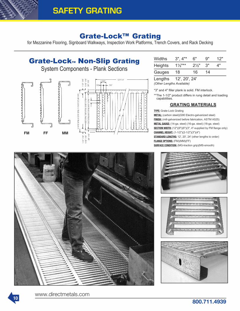
Grate-Lock™ Gratingfor Mezzanine Flooring, Signboard Walkways, Inspection Work Platforms, Trench Covers, and Rack Decking
Grate-LockTM Non-Slip GratingSystem Components - Plank Sections
Widths 3", 4"* 6" 9" 12"Heights 1½"** 2½" 3" 4"Gauges 18 16 14Lengths 12', 20', 24'(Other Lengths Available) *3" and 4" filler plank is solid. FM interlock.**The 1-1/2" product differs in rung detail and loading capabilities.
GRATING MATERIALSTYPE: Grate-Lock GratingMETAL: (carbon steel)(G90 Electro-galvanized steel)FINISH: (mill-galvanized before fabrication, ASTM A525)METAL GAUGE: (14-ga. steel) (16-ga. steel) (18-ga. steel)SECTION WIDTH: (12")(9")(6")(3", 4"-supplied by FM flange only)CHANNEL HEIGHT: (1-1/2")(2-1/2")(3")(4")STANDARD LENGTHS: 12', 20', 24' (other lengths to order)FLANGE OPTIONS: (FM)(MM)(FF)SURFACE CONDITION: (MG-traction grip)(MS-smooth)
SAFETY GRATING

11800.711.4939
www.directmetals.com
PRODUCT DESCRIPTIONPerf-O Grip® is a one-piece metal plank- type grating manufactured by a cold form-ing process in the shape of a channel. The web of the channel is the walking surface, and has large debossed holes, surrounded by smaller embossed traction buttons.
MATERIAL SPECIFICATIONSGrating shall be “Perf-O Grip® Channel,” manufactured from (see “Selections” right) and complete with a (1-1/2", 2", 3") side channel depth.
FEATURES & BENEFITS 1. Embossed traction buttons provide superior slip resistance in all directions and in all weather conditions. 2. Large debossed holes provide maximum drainage of debris or allow up to 50% free air opening, depending on channel width.
3. Self-cleaning due to resilience of walking surface. 4. One-piece metal construction. 5. Light-weight design provides high strength to weight ratio. 6. Long life span requiring little maintenance. 7. Simple and economical installation, as planks are self-framing. 8. Adaptable to cost effective custom fabrication. 9. Can be easily formed in standard channel or custom shapes.
NOTE:1. Tolerance on A, B & C dimensions is ± 1/8"2. Hole pattern shown on diagram is even. Widths indicated with ** have a staggered hole pattern.3. Outside traction buttons on all widths except 18" & 24" width
Perf-O Grip® ChannelSELECTIONS• ASTM-A-526, G-90 (Z-275) Pregalvanized 13 or 11 gauge steel
• ASTM-A-569, HRP&O 13 or 11 gauge steel
• 5052H32 Aluminum .125” thick (up to 18” width)
• Type 316L 2B Stainless Steel 14 gauge (up to 12” width)
• Type 304 2B Stainless Steel 16 gauge (up to 12” width)
Channel Return Hole to Width Flange Channel Edge
“A” “B” “C” **5" 7/8" 1-21/32" 7" 7/8" 1-13/16" 10" 7/8" 1-5/8" **12" 7/8" 1-25/32" **18" 7/8" 1-13/32" 24" 7/8" 1-7/8" **30" 7/8" 2-11/32"
SAFETY GRATING

NON-STANDARD
PERFORATED METAL
12www.directmetals.com
800.711.4939
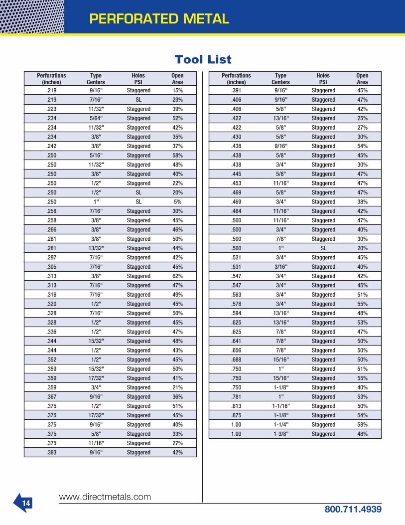
Types of Perforations
SLOTS - SIDE STAGGER SLOTS - END STAGGER SLOTS - STRAIGHT
ROUND PERFORATIONSSTAGGERED
ROUND PERFORATIONSSTRAIGHT LINE PATTERN
ROUND PERFORATIONS45 DEGREE PATTERN
PERFORATED STOCK SIZE SHEETOR PLATE WITH MINIMUM MARGINS
SHEET OR PLATE RESHEARED AFTERPERFORATING WITH MARGINS AS SPECIFIED
STANDARD
SQUARE PERFORATIONS-STAGGERED
SQUARE PERFORATIONS-STRAIGHT

13800.711.4939
www.directmetals.com
PERFORATED METAL
Tool List Perforations Type Holes Open (inches) Centers PSI Area .020 Straight 825 30%
.020 Staggered 625 23%
.023 Straight 576 24%
.023 Staggered 400 18%
.027 Straight 400 23%
.027 Staggered 320 18%
.033 Staggered 225 19%
.033 Straight 330 29%
.040 Straight 225 30%
.040 Staggered 186 23%
.041 Staggered – 32%
.043 Staggered – 35%
.045 Straight 225 37%
.045 Staggered 169 28%
.050 Straight 144 33%
.050 Staggered 115 26%
.055 Straight 144 33%
.055 Staggered 135 30%
.058 Straight 144 38%
.058 Staggered 115 35%
Perforations Type Holes Open (inches) Centers PSI Area .100 5/32" Staggered 36%
.100 9/64" SL 45%
.109 3/16" Staggered 29%
.109 7/32" Staggered 23%
.109 5/32" Staggered 45%
.113 7/32" Staggered 25%
.117 3/16" Staggered 33%
.117 7/32" Staggered 27%
.117 5/32" Staggered 50%
.125 3/16" Staggered 40%
.125 3/16" SL 28%
.125 7/32" Staggered 29%
.125 1/4" Staggered 23%
.125 1/4" SL 20%
.125 5/16" SL 11%
.141 3/16" Staggered 51%
.141 7/32" Staggered 38%
.141 1/4" Staggered 28%
.148 1/4" Staggered 30%
.148 7/32" Staggered 30%
.156 3/16" Staggered 62%
.156 7/32" Staggered 46%
.156 1/4" Staggered 36%
.156 9/32" Staggered 28%
.156 17/64" SL 26%
.156 3/8" Staggered 15%
.172 1/4" Staggered 43%
.172 3/8" Staggered 19%
.172 9/32" Staggered 33%
.180 9/32" Staggered 35%
.188 7/32" Staggered 66%
.188 1/4" Staggered 51%
.188 9/32" Staggered 41%
.188 5/16" Staggered 33%
.188 1/4" SL 55%
.188 9/16" SL 12%
.203 9/32" Staggered 47%
.219 5/16" Staggered 45%
.219 11/32" Staggered 36%
Perforations Type Holes Open (inches) Centers PSI Area .063 3/32" Staggered 40%
.063 1/10" Straight 30%
.063 7/64" Staggered 30%
.063 1/8" Staggered 23%
.067 1/8" Staggered 28%
.071 1/8" Staggered 30%
.077 7/64" Staggered 45%
.078 1/8" Staggered 36%
.079 7/64" Straight 45%
.083 1/8" Staggered 37%
.083 5/32" Staggered 26%
.093 9/64" Staggered 40%
.093 5/32" Staggered 33%
.093 11/64" Staggered 26%
.093 3/16" Staggered 23%
.093 3/16" SL 20%
.093 17/64" (45°) Staggered 11%
.093 1/4" Staggered 13%
14www.directmetals.com
800.711.4939
Tool List Perforations Type Holes Open (inches) Centers PSI Area .391 9/16" Staggered 45%
.406 9/16" Staggered 47%
.406 5/8" Staggered 42%
.422 13/16" Staggered 25%
.422 5/8" Staggered 27%
.430 5/8" Staggered 30%
.438 9/16" Staggered 54%
.438 5/8" Staggered 45%
.438 3/4" Staggered 30%
.445 5/8" Staggered 47%
.453 11/16" Staggered 47%
.469 5/8" Staggered 47%
.469 3/4" Staggered 38%
.484 11/16" Staggered 42%
.500 11/16" Staggered 47%
.500 3/4" Staggered 40%
.500 7/8" Staggered 30%
.500 1" SL 20%
.531 3/4" Staggered 45%
.531 3/16" Staggered 40%
.547 3/4" Staggered 42%
.547 3/4" Staggered 45%
.563 3/4" Staggered 51%
.578 3/4" Staggered 55%
.594 13/16" Staggered 48%
.625 13/16" Staggered 53%
.625 7/8" Staggered 47%
.641 7/8" Staggered 50%
.656 7/8" Staggered 50%
.688 15/16" Staggered 50%
.750 1" Staggered 51%
.750 15/16" Staggered 55%
.750 1-1/8" Staggered 40%
.781 1" Staggered 53%
.813 1-1/16" Staggered 50%
.875 1-1/8" Staggered 54%
1.00 1-1/4" Staggered 58%
1.00 1-3/8" Staggered 48%
Perforations Type Holes Open (inches) Centers PSI Area .219 9/16" Staggered 15%
.219 7/16" SL 23%
.223 11/32" Staggered 39%
.234 5/64" Staggered 52%
.234 11/32" Staggered 42%
.234 3/8" Staggered 35%
.242 3/8" Staggered 37%
.250 5/16" Staggered 58%
.250 11/32" Staggered 48%
.250 3/8" Staggered 40%
.250 1/2" Staggered 22%
.250 1/2" SL 20%
.250 1" SL 5%
.258 7/16" Staggered 30%
.258 3/8" Staggered 45%
.266 3/8" Staggered 46%
.281 3/8" Staggered 50%
.281 13/32" Staggered 44%
.297 7/16" Staggered 42%
.305 7/16" Staggered 45%
.313 3/8" Staggered 62%
.313 7/16" Staggered 47%
.316 7/16" Staggered 49%
.320 1/2" Staggered 45%
.328 7/16" Staggered 50%
.328 1/2" Staggered 45%
.336 1/2" Staggered 47%
.344 15/32" Staggered 48%
.344 1/2" Staggered 43%
.352 1/2" Staggered 45%
.359 15/32" Staggered 50%
.359 17/32" Staggered 41%
.359 3/4" Staggered 21%
.367 9/16" Staggered 36%
.375 1/2" Staggered 51%
.375 17/32" Staggered 45%
.375 9/16" Staggered 40%
.375 5/8" Staggered 33%
.375 11/16" Staggered 27%
.383 9/16" Staggered 42%
PERFORATED METAL

15800.711.4939
www.directmetals.com
Round HolesA FEW OF OUR PERFORATIONS - (holes at actual size)
1/16" @ 1/8"STAGGEREDOpen area . . . 22.5%
.078 @ 1/8"STAGGEREDOpen area . . . 36%
3/32" @ 5/32"STAGGEREDOpen area . . . 32%
3/32" @ 3/16"STAGGEREDOpen area . . . 23%
1/8" @ 3/16"STAGGEREDOpen area . . . 40%
1/8" @ 1/4"STAGGEREDOpen area . . . 23%
5/32" @ 7/32"STAGGEREDOpen area . . . 46%
3/16" @ 1/4"STAGGEREDOpen area . . . 51%
3/16" @ 5/16"STAGGEREDOpen area . . . 33%
1/4" @ 5/16"STAGGEREDOpen area . . . 58%
1/4" @ 3/8"STAGGEREDOpen area . . . 40%
3/8" @ 9/16"STAGGEREDOpen area . . . 40%
7/16" @ 9/16"STAGGEREDOpen area . . . 51%
1/2" @ 11/16"STAGGEREDOpen area . . . 47%
1/2" @ 3/4"STAGGEREDOpen area . . . 40%
3/4" @ 1"STAGGEREDOpen area . . . 51%
1" @ 1-1/4"STAGGEREDOpen area . . . 58%
MANY ADDITIONAL PERFORATIONS AVAILABLE . . . ASK YOUR DIRECT METALS SALESPERSONWE CAN PERFORATE MOST ANY METAL, PLASTIC OR RUBBER.
PERFORATED METAL

16www.directmetals.com
800.711.4939
airport parking Deck
SunScreenS 20ga Steel peg BoarD
Formulas for Determining Percentage of Open AreasIn each formula “D” = hole diameter and “C” = center spacing
60˚ Staggered CentersPattern (Standard)
Dia2
Center2
x90.5
=Percentage of Open Area
Straight Line PatternDia2
Center2
x78.54
=Percentage of Open Area
45˚ StaggeredCenters Pattern
Dia2
Center2
x157.08
=Percentage of Open Area
Signage
patio Furniture
architectural BuilDing FaScia
PERFORATED METAL

17800.711.4939
www.directmetals.com
BAR GRATING
Glossary TerminologyANCHOR - A device by which grating isattached to its supports. BAND - A flat bar welded to the end of a grating panel or along the line of a cutout, and extending neither above nor below the bearing bars. Load-Carrying Band: A band used in a cutout to transfer the load from unsupported bearing bars to the supported bearing bars. Trim Band: A band which carries no load but is used chiefly to improve appearance. BEARING BARS - Load-carrying bars made from steel strip, slit sheet or rolled or extruded aluminum, and extending in thedirection of the grating span. BEARING BAR CENTERS - The distance center to center of the bearing bars. CARRIERS - Flats or angles, which are welded to the grating panel and nosing of a stair tread, and are bolted to a stair stringer to support the tread. CLEAR OPENING - The distance between faces of bearing bars in a rectangulargrating or between a bent connecting bar and a bearing bar in a riveted grating. CROSS BARS - The connecting bars made from steel strip, slit sheet, rolled bars, or rolled or extruded aluminum, which extend across the bearing bars, usually perpendicular to them. They may be bent into a corrugated or sinuous pattern where they intersect, the bearing bars are welded, forged, or mechanically locked to them. CROSS BAR CENTERS - The distance center to center of the cross bars. CURVED CUT - A cutout following a curved pattern. CUTOUT - An area of grating removed to clear an obstruction or to permit pipes, ducts, columns, etc. to pass through the grating. ELECTRO-FORGED - A process combin-ing hydraulic pressure and heat fusion to forge bearing bars and cross bars into a panel grid. FINISH - The coating, usually paint orgalvanizing, which is applied to the grating. FLUSH TOP GRATING - A type of pressure-locked grating, in which the cross bars and bearing bars are in the same plane relative to the top surface of the grat-ing. GRATING - An open grid assembly of metal bars, in which the bearing bars running in one direction are spaced by rigid attachment to cross bars running perpen-dicular to them, or by bent connecting bars extending between them.
HINGED PANELS - Grating panels which are hinged to their supports or to other grating parts. I-BAR - An extruded aluminum bearing bar having a cross sectional shape resembling the letter “I”. LENGTH - The dimension of a grating panel measured parallel to the bearing bars. Also referred to as span. LOAD-CARRYING BAND - see Band. NOSING - A special L-section member serving as the front or leading edge of a stair tread or of grating at the head of a stair. PRESSURE-LOCKED GRATING - Grating in which the cross bars are mechanically locked to the bearing bars at their intersections by deforming orswaging the metal. RADIALLY CUT GRATING - Rectangular grating which is cut into panels shaped as annular segments, for use in circular or annular areas. RETICULINE BAR - A sinuously bent connecting bar extending between two adjacent bearing bars, alternately contact-ing and being riveted to each. RIVET CENTERS - The distance center to center of rivets along one bearing bar. RIVETED GRATING - Grating composed of straight bearing bars and bent connect-ing bars, which are joined at their contact points by riveting. SERRATED GRATING - Grating which has the top surfaces of the bearing bars, cross bars or both notched. SPAN OF GRATING - The distancebetween points of grating support, or thedirection of the dimension. Also referred to as length. STRAIGHT CUT - That portion of the cut edge or cutout of a grating, which follows a straight line. SWAGING - A method of altering the cross-sectional shape of a metal bar by pressure applied through dies. TOEPLATE - A flat bar attached against the outer edge of a grating or rear edge of a tread, and projecting above the top surface of grating or tread to form a lip or curb. TREAD - A panel of grating having carriers and nosing attached by welding, and de-signed specifically to serve as a stair tread. WELDED GRATING - Grating in which the bearing bars and cross bars are joined at their intersections by a weld. WIDTH - The overall dimension of a grating panel, measured perpendicular to the bear-ing bars and in the same direction as the cross bars.
This catalog uses a form of the NAAMM alpha-numeric designation for bar spacing and manufacturing identification. The first number signifies center-to-center bearing bar spacing in 1/16ths of an inch*. A letter designates method of manufacture. The last number details center-to-center cross bar spacing in whole inches (usually 4" or 2")or rivet spacing (usually 3-1/2", 5" or 7").
Methods of manufacturing and their letter designations used in this catalog include: SG ........ Swaged Rectangular Bar SGF ...... Swaged Flush Top SGI ....... Swaged I-Bar W .......... Welded Steel R .......... Riveted (Steel) AR ........ Riveted (Aluminum)
FOR EXAMPLE:
19-W-4 – Bearing Bars 19/16" (or 1-3/16") c.c. – Welded Steel Construction – Cross Bars 4" c.c. 15-SGI-2 – Bearing Bars 15/16" c.c. – Swaged I-Bar – Cross Bars 2" c.c.
Other Bearing Bar Spacings commonly used throughout the industry are designated thus: 38-W-4 (or 2) Bearing Bars 38/16" c.c. (2-3/8" c.c.) 30-W-4 (or 2) Bearing Bars 30/16" c.c. (1-7/8" c.c.) 22-W-4 (or 2) Bearing Bars 22/16” c.c. (1-3/8” c.c.) 11-SG-4 (or 2) Bearing Bars 11/16" c.c. 7-SG-4 (or 2) Bearing Bars 7/16" c.c. 18-R-7 (or 3-1/2) Bearing Bars 18/16" face-to-face (1-1/8")* 37-R-5 Bearing Bars 37/16" face-to-face (2-5/16")* 12-R-7 (or 3-1/2) Bearing Bars 12/16" face-to-face (3/4")*
*Note: Riveted grating marking indicates space between bearing bars.

BAR GRATING
18www.directmetals.com
800.711.4939
ALUMINUM RIVETEDA type of aluminum
grating, which combines
straight bearing bars and bent
connectingbars riveted together at their contact points. Riveted grating, although being the oldest style of industrial footwalk, is still the choice of many engineers due to its reliability and durability. All popular sizes and spacings of riveted grating are available.
ALUMINUM PLANKA type of
extruded grat-ing, which is
available In 6" wide sections, and either
plain sided or Interlocking. Plank can be
provided in sections up to 26'0" in length, or fabricated per plans and specs. Plank grating is available unpunched as an eco-nomical and structurally superior substitute for aluminum checkerplate, or with a vari-ety of punch/patterns.
Aluminum ProductsALUMINUM
FLUSH TOP A type of pressure
locked grating in which the cross
bars are in the same plane rela-tive to the top surface
of the grating. Bearing bar sizes range from 1" x 1/8" through 2-1/2" x 3/16" in 1/4" increments. Bearing bar spacing of 13/16", 15/16", 11/16" and 7/16" c.c. and cross bar spacing of 4" or 2" are available. Where skid resistance is desired, a serrated surface can be provided.
ALUMINUM RECTANGULAR
BARA type of
pressure lockedgrating madeby
permanentlyattaching cross bars to bearing bars through a pressure applied swaging pro-cess. Bearing bar sizes range from1" x 1/8" through 2-1/2" x 3/16" in 1/4"increments. Bearing bar spacing of 13/16", 15/16", 11/16" and 7/16" c.c., with cross bar spacing of 4" or 2" are available. Where skid resistance is desired, aserrated surface can be provided.
ALUMINUM I-BARA type of pressure
locked grating, which utilizes
an “I” shaped bearing bar ranging in size from 1" x 1/4" through
2-1/2" x1/4" in 1/4" increments. Bearing bar spacing of 13/16" and 15/16" c.c. and cross bar spacings of 4" or 2" are available. The I-Bar design takes advantage of the aluminum extru-sion process by placing the metal where it is most effective, at the outermost fiber, while reducing the thickness of the neutral axis web. This design consideration allows the same load carrying capacity at less weight per square foot than rectangular bar, therefore resulting in a cost savings.
PRESSURE LOCKINGThe most common method of manufactur-ing aluminum bar grating is through a process known as pressure locking.
Pressure locked grating as de-fined by the NAAMM
Metal Bar Grat-ing Manual is “Grating in which the cross bars aremechanically locked to
the bearing bars at their intersections by deforming or swaging the metal.” Direct Metals provides a permanently attached pressure locked joint, which will give long lasting life under normal service conditions.
Aluminum Plank Grating
GRATING TYPES AVAILABLE IN ALUMINUM
Where economy is a major consideration, the I-Bar SGI Series offers a popular andreasonably priced alternative to rect-angular bar grating. Extruded I-Bar sections have the same load carrying capacity, with less weight per square foot than rectangular bars. The stri-ated top and bottom flanges provide a “built-in” skid resistance feature without the added cost of serrating.

19800.711.4939
www.directmetals.com
BAR GRATING
Aluminum 19 Space (1-3/16") Load Table
0.329
0.206 1 - 1/4 x 1/8 47 2.08
1 - 1/4 x 3/16 3.01 0.493
2.34 0.308
0.474
0.355
52
1 - 1/2 x 1/8
1 - 1/2 x 3/16 3.56 0.711
1 - 3/4 x 3/16
2 x 3/16
2 - 1/4 x 3/16
2 - 1/2 x 3/16 5.79 1.974
5.24 1.599
4.68 1.263
0.9674.12
2.70 0.533
4.15 2.467
3.75 1.798
3.43 1.263
0.8463.06
53
59
66
73
80
87
2.46
1.99 0.158
1 x 1/8 39 1.710.211
0.105
1 x 3/1644
2.46 0.316
UDCDUDCDUDCDUDCDUDCDUDCDUDCDUDCDUD CDUDCD
4210.144
4210.115
6320.144
6320.115
6580.115
6580.092
9870.115
9870.092
9470.096
9470.07714210.09614210.07719340.08219340.06625260.07225260.05831970.06431970.05139470.05839470.046
2690.225
3370.180
4040.255
5050.180
4210.180
5260.144
6320.180
7890.144
6060.150
7580.120
9090.15011370.12012380.12915470.10316170.11320210.09020460.10025580.08025260.09031580.072
1870.324
2810.259
2810.324
4210.259
2920.259
4390.207
4390.259
6580.207
4210.216
6320.173
6320.216
9470.173
8600.18512890.14811230.16216840.13014210.14421320.11517540.13026320.104
137.441241
0.353206
0.441361
0.353215
0.353376
0.282322
0.353564
0.282309
0.294541
0.235464
0.294812
0.235632
0.25211050.202
8250.22114440.17610440.19618270.15712890.17622560.141
1580.576
3160.461
1640.461
3290.369
2470.461
4930.369
2370.384
4740.307
3550.384
7110.307
4840.329
9670.263
6320.2881263
0.230799
0.2561599
0.205987
0.2301974
0.184
1950.583
4390.467
1870.486
4210.389
2810.486
6320.389
3820.417
8600.333
4990.36511230.292
6320.32414210.259
7800.29217540.233
2270.600
5680.480
3090.514
7740.411
4040.45010110.360
5120.40012790.320
6320.36015790.288
2560.622
7030.498
3340.545
9190.436
4230.48411630.387
5220.43614350.348
2150.741
6450.592
2810.648
8420.518
3550.57610660.461
4390.51813160.415
2390.761
7770.608
3030.676
9840.541
3740.60812150.487
2610.784
9140.627
3220.7061128
0.564
2470.922
9870.737
Bar Size,Inches
PedSpanInches
Wt.*Lbs.
Sq. Ft. 2'- 0" 2'- 6" 3'- 0" 3'- 6" 4'-0" 4'- 6" 5'- 0" 5'- 6" 6'- 0" 6'- 6" 7'- 0" 8'- 0"
Sec. PropSx*, in3
Ix*, in4
U - Safe uniform load in pounds sq. ft.C - Safe concentrated load in pounds/ft. grating widthD - Deflection in inches
Loads and deflections given in this table are theoretical and are based on a unit stress of 12,000 psi.
Clear Span
Panel Width Chart (in.) 19-SG-4/19SG-2 Dimensions Are Out-to-Out of Bearing Bars**
**Bar thickness is 1/4" at top and bottom. Add 1/4" for extended cross bars. Standard panel widths indicated in bold.
No. of Bars 2 3 4 5 6 7 8 9 1/4" Flange 1-7/16 2-5/8 3-13/16 5 6-3/16 7-3/8 8-9/16 9-3/4
No. of Bars 10 11 12 13 14 15 16 17 1/4" Flange 10-15/16 12-1/8 13-5/16 14-1/2 15-11/16 16-7/8 18-1/16 19-1/4 No. of Bars 18 19 20 21 22 23 24 25 1/4" Flange 20-7/16 21-5/8 22-13/16 24 25-3/16 26-3/8 27-9/16 28-3/4
No. of Bars 26 27 28 29 30 31 1/4" Flange 29-15/16 31-1/8 32-5/16 33-1/2 34-11/16 35-7/8
I-Bar
I-Bar
I-Bar
I-Bar
I-Bar
I-Bar
I-Bar

20www.directmetals.com
800.711.4939
BAR GRATING
Aluminum I-Bar & Rectangular Bar (SGI Series)7-SGI-4 7-SGI-2
7/16"
7-SGI-4 4"
SPAN
7/16"
7-SGI-2
SPAN
2"
7-SGI-4 7-SGI-2 Panel Width Chart (in.) Dimensions Are Out-to-Out of Bearing Bars** No. of Bars 2 3 4 5 6 7 8 9 10 11 12 13 14 15 16 1/4" Flange 11/16 1-1/8 1-9/16 2 2-7/16 2-7/8 3-5/16 3-3/4 4-3/16 4-5/8 5-1/16 5-1/2 5-15/16 6-3/8 6-13/16 No. of Bars 17 18 19 20 21 22 23 24 25 26 27 28 29 30 31 1/4" Flange 7-1/4 7-11/16 8-1/8 8-9/16 9 9-7/16 9-7/8 10-5/16 10-3/4 11-3/16 11-5/8 12-1/16 12-1/2 12-15/16 13-3/8 No. of Bars 32 33 34 35 36 37 38 39 40 41 42 43 44 45 46 1/4" Flange 13-13/16 14-1/4 14-11/16 15-1/8 15-9/16 16 16-7/16 16-7/8 17-5/16 17-3/4 18-3/16 18-5/8 19-1/16 19-1/2 19-15/16 No. of Bars 47 48 49 50 51 52 53 54 55 56 57 58 59 60 61 1/4" Flange 20-3/8 20-13/16 21-1/4 21-11/16 22-1/8 22-9/16 23 23-7/16 23-7/8 24-5/16 24-3/4 25-3/16 25-5/8 26-1/16 26-1/2
No. of Bars 62 63 64 65 66 67 68 69 70 71 72 73 74 75 76 1/4" Flange 26-15/16 27-3/8 27-13/16 28-1/4 28-11/16 29-1/8 29-9/16 30 30-7/16 30-7/8 31-5/16 31-3/4 32-3/16 32-5/8 33-1/16 No. of Bars 77 78 79 80 81 82 83 1/4" Flange 33-1/2 33-15/16 34-3/8 34-13/16 35-1/4 35-11/16 36-1/8
**Bar thickness is 1/4" at top and bottom. Add 1/4" for extended cross bars.
*Based on 27.429 bars/ft. of grating width. Bearing bars 7/16" c.c. Add .3 lbs./sq. ft. for 7-SG-2. 1/8" bearing bars available by inquiry. Note: Grating for spans to the left of the heavy line have a deflection less than 1/4" for uniform loads of 100 lbs./sq. ft. This is the maximum deflection to afford pedestrian comfort and can be exceeded for other types of load at the discretion of the engineer.
PedSpan,Inches
56
66
76
85
94
103
111
Wt.*Lbs.
Sq. Ft.
6.30
7.78
9.28
10.80
12.32
13.83
15.33
Sec. PropSx*, in3
Ix*, in4
0.857
0.429
1.339
0.837
1.929
1.446
2.625
2.297
3.429
3.429
4.339
4.882
5.357
6.697
UDCDUDCDUDCDUDCDUDCDUDCDUDCD
ClearSpan
2'- 0" 2'- 6" 3'- 0" 3'- 6" 4'- 0" 4'- 6" 5'- 0" 5'- 6" 6'- 0" 6'- 6" 7'- 0" 8'- 0"17140.14417140.11526790.11526790.09238570.09638570.07752500.08252500.06668570.07268570.05886790.06486790.051107140.058107140.046
10970.22513710.18017140.18021430.14424690.15030860.12033600.12942000.10343890.11354860.09055540.10069430.08068570.09085720.072
7620.32411430.25911900.25917860.20717140.21625710.17323330.18535000.14830480.16245720.13038570.14457860.11547620.13071430.104
5600.441
9800.353
8750.35315310.28212590.29422040.23517140.25230000.20222390.22039180.17628340.19649590.15734990.17661230.141
4290.577
8570.461
6700.46113390.369
9640.38419290.30713130.32926250.26317140.28834290.23021700.25643390.20526790.23053570.184
3390.730
7620.583
5290.58311900.466
7620.48617140.38910370.41723330.33313550.36530480.29217140.32438570.25921160.29247620.233
2740.899
6860.720
4290.72110710.576
6170.60015430.480
8400.51421000.41110970.45027430.36013890.40034710.32017140.36042860.288
3540.871
9740.697
5100.72614030.581
6940.62219090.498
9070.54524940.43611480.48431560.38714170.43638960.348
2981.038
8930.830
4290.86512860.691
5830.74017500.592
7620.64822860.518
9640.57628930.46111900.51835710.415
3651.01411870.811
4970.86916150.695
6490.76021100.608
8220.67626700.54110140.60832970.487
U - Safe uniform load in pounds/sq. ft.C - Safe concentrated load in pounds/ft. grating widthD - Deflection in inches
Loads and deflectionsgiven in this table are the-oretical, and are based on a unit stress of 12,000 psi.
4291.00915000.806
5600.88219590.706
7080.78324800.627
8750.70630610.564
3281.31613131.054
4291.15317140.921
5421.02321700.819
6700.92226790.737
Bar Size,Inches
1 x 3/16
1-1/4 x 3/16
1-1/2 x 3/16
1-3/4 x 3/16
2 x 3/16
2-1/4 x 3/16
2-1/2 x 3/16
1" I-Bar
1-1/4" I-Bar
4.79
5.75
1-1/2" I-Bar 6.74
1-3/4" I-Bar 7.70
2" I-Bar 8.71
2-1/4" I-Bar 9.59
2-1/2" I-Bar 10.66

21800.711.4939
www.directmetals.com
Aluminum Plank Section AvailabilityAluminum Plank is structurally sound and cosmetically attractive. Plank grating is non-sparking, non-magnetic, non-skid and relatively maintenance free. It is durable, corrosion resistant, and possesses a high strength-to-weight ratio. The surface can be provided unpunched or with a variety of punch/patterns for the passage of air, light, heat or moisture. The interconnecting webs offer a flush top walking surface. Aluminum plank grating has found application in sew-age and waste water treatment plants, as well as in the marine refrigerator (reefer), freezers and cargo-hold flooring market.Aluminum plank grating is available in five cross-sectional designs: Heavy Duty (plain sides), Heavy Duty (interlocking sides), Light Series (plain sides), Reefer (plain sides) and Reefer (interlocking sides).
The Heavy Duty sections are used primarily in water and waste treatment and the marine markets, while the Light Series and Reefer sections are exclusively in the marine refrigerator applications.Interlocking Heavy Duty, Reefer sections and edge sections are available in 1" deep grating only.
Plank Punch / Pattern AvailabilityAluminum plank grating is available unpunched or with a variety of punch/patterns as shown below. Rectangular or square punched holes are most commonly used for water and waste treatment plants, and in marine applications, while the round holes find applications primarily in the marine market. The surface of plank grating can be specified as plain, or with one of two styles of upsets designed to promote a slip resistant walkway, especially in the presence of moisture, oil or other spilled substances.
REEFER (Plain Sides)
REEFER PUNCH/PATTERNAVAILABILITY
HEAVY DUTY (Plain Sides)
3/4"thru
2-1/2"
1.200" 1.200"
6"1" only
1.500"
6"
3" FEMALE EDGE 3" MALE EDGE
1" only
1" only
1.500"
1.500" 1.500"
6"
HEAVY DUTY (Interlocking Sides)
LIGHT SERIES (Plain Sides)
1.200"
1.200"
1.200"2.400"
1.200"
2-1/2" FEMALE EDGE 2-1/2" MALE EDGE
1" only
1" only
1" only
6"
6"
REEFER (Interlocking Sides)
ADA Compliant
BAR GRATING

22www.directmetals.com
800.711.4939
BAR GRATING
TiteWeld® 7-TW-4 Welded Steel IN STOCK!!
7-TW-4
SPAN SPAN
7/16"
7-TW-4 4"
7/16"
7-TW-2 2"
7-TW-4
TiteWeld® super narrow welded grating - ideal for those very tight spacing requirements when you need maximum “roll-a-bility.”
TiteWeld® satisfies both ADA comfort requirements for wheel chairs and walking pedestrians.
TiteWeld® is IN STOCK and ready to ship.
Panel Width Chart (in.) 7-TW-4 TiteWeld® Dimensions Are Out-to-Out of Bearing Bars** No. of Bars 2 3 4 5 6 7 8 9 10 11 12 13 14 15 16 3/16" Bars 5/8 1-1/16 1-1/2 1-15/16 2-3/8 2-13/16 3-1/4 3-11/16 4-1/8 4-9/16 5 5-7/16 5-7/8 6-5/16 6-3/4 No. of Bars 17 18 19 20 21 22 23 24 25 26 27 28 29 30 31 3/16" Bars 7-3/16 7-5/8 8-1/16 8-1/2 8-15/16 9-3/8 9-13/16 10-1/4 10-11/16 11-1/8 11-9/16 12 12-7/16 12-7/8 13-5/16 No. of Bars 32 33 34 35 36 37 38 39 40 41 42 43 44 45 46 3/16" Bars 13-3/4 14-3/16 14-5/8 15-1/16 15-1/2 15-15/16 16-3/8 16-13/16 17-1/4 17-11/16 18-1/8 18-9/16 19 19-7/16 19-7/8 No. of Bars 47 48 49 50 51 52 53 54 55 3/16" Bars 20-5/16 20-3/4 21-3/16 21-5/8 22-1/16 22-1/2 22-15/16 23-3/8 23-13/16
**Add 1/4" for extended cross bars. Deduct 1/16" for 1/8" bearing bars. Standard panel widths indicated in bold.
*Based on 27.429 bars/ft. of grating width. Bearing bars 7/16" c.c. Add .6 lbs./sq. ft. for 7-TW-2. 1/8" bearing bars available upon inquiry. Note: Grating for spans to the left of the heavy line have a deflection less than 1/4" for uniform loads of 100 lbs./sq. ft. This is the maximum deflection to afford pedestrian comfort, and can be exceeded for other types of load at the discretion of the engineer. The actual “Ped (pedestrian) Span” under this condi-tion is shown above for each size of grating. When serrated grating is specified, the depth of grating required for a specific load will be 1/4" greater than that shown in these tables. 3/4" x 3/16" serrated grating is NOT available.
IN STOCK!!
ADA Compliant
Wt.*Lbs.
Sq. Ft.
13.73
18.09
22.45
26.81
31.20
35.59
39.92
44.31
UDCDUDCDUDCDUDCDUDCDUDCDUDCDUDCD
ClearSpan
2'- 0" 2'- 6" 3'- 0" 3'- 6" 4'- 0" 4'- 6" 5'- 0" 5'- 6" 6'- 0" 6'- 6" 7'- 0" 8'- 0"1446.099
1446.079
2571.074
2571.060
4018.060
4018.048
5786.050
5786.040
7875.043
7875.034
10286.037
10286.030
13018.033
13018.026
16072.030
16072.030
926.155
1157.124
1646.116
2057.093
2571.093
3214.074
3703.078
4629.062
5040.067
6300.053
6583.058
8229.047
8332.052
10414.041
10286.047
12857.037
643.223964.179
1143.168
1714.134
1786.134
2679.107
2571.112
3857.089
3500.096
5250.077
4572.084
6857.067
5786.074
8679.060
7143.067
10714.054
472.304827.243840.228
1469.182
1312.182
2296.146
1889.152
3306.122
2571.130
4500.104
3359.114
5878.091
4251.101
7439.081
5248.091
9184.073
362.398723.318643.298
1286.238
1004.238
2009.191
1446.199
2893.159
1969.170
3938.136
2571.149
5143.119
3255.132
6509.106
4018.119
8036.095
286.503643.402508.377
1143.302794.302
1786.241
1143.251
2571.201
1556.216
3500.172
2032.189
4572.151
2571.168
5786.134
3175.151
7143.121
231.620579.497411.465
1029.373643.372
1607.298926.310
2314.248
1260.266
3150.213
1646.233
4114.186
2083.270
5207.166
2571.186
6429.149
340.563935.451531.450
1461.360765.375
2104.300
1041.322
2864.258
1360.282
3740.225
1721.250
4734.200
2125.225
5844.180
286.671857.536446.536
1339.429643.447
1929.358875.383
2625.306
1143.335
3429.268
1446.298
4339.238
1786.268
5357.215
380.629
1236.503548.525
1780.420746.450
2423.360974.393
3165.315
1232.350
4006.280
1522.315
4945.252
U - Safe uniform load in pounds/sq. ft.C - Safe concentrated load in pounds/ft. grating widthD - Deflection in inches
Loads and deflectionsgiven in this table aretheoretical, and are based on a unit stress of 18,000 psi.
328.730
1148.584472.608
1653.487643.521
2250.417840.456
2939.365
1063.406
3719.324
1312.365
4592.292
251.953
1004.762362.795
1446.635492.681
1969.545643.596
2571.477814.530
3255.424
1004.476
4018.381
Bar Size,Inches
3/4 x 3/16
1 x 3/16
1-1/4 x 3/16
1-1/2 x 3/16
1-3/4 x 3/16
2 x 3/16
2-1/4 x 3/16
2-1/2 x 3/16

23800.711.4939
www.directmetals.com
Light Duty Steel Design CriteriaThe tables of safe loads which follow have been computed using the following design parameters:
U = Uniform Load - lbs/ft2
C = Concentrated Load - lbs/ft of grating width
S = Section Modulus - in3/ft of grating width
I = Moment of Inertia - in4/ft of grating width
L = Simple Clear Span - feet
D = Deflection - inches
E = Modulus of Elasticity (30,000,000 psi)
F = Allowable Bending Stress (18,000 psi)
M = Bending Moment
Light Duty Welded Steel (W Series)
GRATING TYPES - LIGHT DUTY WELDED STEEL W SERIES
HOW TO SPECIFY: 1. Grating: Light Duty Welded Steel W Series. 2. Bearing Bars: Rectangular Bar on 1-3/16" centers maximum. (Note: Other spacings may be specified at the discretion of the architect/ engineer.) 3. Cross Bars: Electroforge welded at right angles to bearing bars at 4" centers maximum. (Note: 2" cross bar centers may be specified at the discretion of the architect/engineer.) 4. Surface: Plain. (Note: A serrated surface may be specified for maximum skid resistance.) 5. Loading: Grating to carry a pedestrian loading equal to 100# per square foot over the required clear span with deflection not to exceed 1/4". (Note: Alternate loading requirements may be specified at the discretion of the architect/engineer.) 6. Finish: Galvanized or manufacturer’s standard black paint at the discretion of the architect/engineer. 7. Fabrication and Tolerances: In accordance with the NAAMM Metal Bar Grating Manual.
For those areas requiring the corrosion resistance of stainless steel, Direct Metals stocks 1" x 3/16", 1-1/4" x 3/16" and1-1/2" x 3/16" 19-W-4 Type 304 stainless steel electroforge welded grating. Since the welding process discolors the stain-less surface, this grating is best suited for industrial applications only and should not be specified where cosmetic appearance is important.
Serrated Surface
BAR GRATING

24www.directmetals.com
800.711.4939
BAR GRATING
Light Duty Welded Steel
0.316
0.158
1 x 3/16 57 7.04
0.329
0.206
0.493
0.308
61 5.961 - 1/4 x 1/8
1 - 1/4 x 3/16
0.474
1.599
1.974
1.263
0.967
0.711
0.355
1.798
2.467
1.263
0.846
0.533
67
70 7.041 - 1/2 x 1/8
77 10.251 - 1/2 x 3/16
87 11.871 - 3/4 x 3/16
96 13.482 x 3/16
105
113
15.08
16.70
2 - 1/4 x 3/16
2 - 1/2 x 3/16
8.64
0.105
3/4 x 3/16 46 5.43
0.178
0.067
51 4.881 x 1/80.211
UDCDUDCDUDCDUDCDUDCDUDCDUDCDUDCDUD CDUDCDUDCD
5330.099
5330.079
6320.075
6320.060
9470.074
9470.060
9870.060
9870.04814800.06014800.04814210.05014210.04021320.05021320.04029010.04329010.03437890.03737890.03047960.03347960.02659210.03059210.024
3410.155
4260.124
4040.116
5050.093
6060.116
7580.093
6320.093
7890.074
9470.09311840.074
9090.07811370.06213640.07817050.06218570.06723210.05324250.05830320.04730690.05238370.04137890.04747370.037
2370.224
3550.179
2810.168
4210.134
4210.168
6320.134
4390.134
6580.107
6580.134
9870.107
6320.112
9470.089
9470.11214210.08912890.09619340.07716840.08425260.06721320.07431970.06026320.06739470.054
1740.304
3050.244
2060.228
3610.183
3090.228
5410.182
3220.182
5640.146
4830.182
8460.146
4640.152
8120.122
6960.15212180.122
9470.13016580.10412370.11421650.09115660.10127410.08119330.09133830.073
1330.397
2660.317
1580.298
3160.239
2370.298
4740.239
2470.239
4930.191
3700.238
7400.191
3550.198
7110.159
5330.19910660.159
7250.17014510.136
9470.14918950.11911990.13223980.10614800.11929600.095
1250.378
2810.302
1870.377
4210.302
1950.302
4390.242
2920.301
6580.241
2810.252
6320.201
4210.251
9470.201
5730.21512890.172
7490.18916840.151
9470.16821320.13411700.15126320.121
1520.467
3790.372
1580.373
3950.298
2370.373
5920.298
2270.310
5680.248
3410.310
8530.248
4640.26611600.213
6060.23315160.186
7670.20719180.165
9470.18623680.149
1300.449
3590.361
1960.451
5380.360
1880.376
5170.300
2820.376
7750.301
3840.32210550.257
5010.28213780.225
6340.25017440.200
7830.22521530.180
1640.535
4930.429
1580.447
4740.358
2370.447
7110.358
3220.383
9670.306
4210.33512630.268
5330.29815990.238
6580.26819740.215
2020.525
6560.420
2750.450
8930.360
3590.39411660.315
4540.35014760.280
5610.31518220.252
2370.522
8290.417
3090.45610830.365
3920.40613700.324
4830.36516920.292
1810.680
7250.545
2370.596
9470.477
3000.53011990.424
3700.47714800.381
Bar Size,Inches
PedSpanInches
Wt.*Lbs.
Sq. Ft. 2'- 0" 2'- 6" 3'- 0" 3'- 6" 4'- 0" 4'- 6" 5'- 0" 5'- 6" 6'- 0" 6'- 6" 7'- 0" 8'- 0"
Sec. PropSx*, in3
Ix*, in4
U - Safe uniform load in pounds sq. ft.C - Safe concentrated load in pounds/ft. grating widthD - Deflection in inches
Loads and deflections given in this table are theoretical, and based on a unit stress of 18,000 psi.
Clear Span
*Based on 10.105 bars/ft. of grating width. Bearing bars 1-3/16" c.c. Add .6 lbs./sq. ft. for 19-SGCS-2. Note: Grating for spans to the left of the heavy line have a deflection less than 1/4" for uniform loads of 100 lbs./sq. ft. This is the maximum deflection to afford pedestrian comfort, and can be exceeded for other types of load at the discretion of the engineer. The actual “Ped (pedestrian) Span” under this condition is shown above for each size of grating. When serrated grating is specified, the depth of grating required for a specific load will be 1/4" greater than that shown in these tables. 3/4" x 3/16" serrated grating is NOT available.

25800.711.4939
www.directmetals.com
Heavy Duty Welded Steel (W Series)
SLIP-NOT Grip Grate Safety Surface Available
Plain Surface Serrated Surface
Heavy duty welded grating ranges in size from 1-1/4" X 1/4" bearing bars through6" x 1/2" (7" bearing bars available byinquiry). Standard bearing bar spacings are 15/16", 13/16",1-3/8", 1-7/8" and 2-3/8"center-to-center. See pages 25 and 27 for standard cross bar design. Rectangular cross bars are also available. Standard cross bar spacings are 4" or 2"center-to-center.
HOW TO SPECIFY:
1. Grating: Heavy Duty Welded Steel W Series by Direct Metals or approved equal. 2. Bearing Bars: To be (size) rectangular bar spaced (as specified) inches center-to-center. (Note: Bearing bar size selection and spacing must be coordinated with the load and span conditions.)
3. Cross Bars: To be (size) spaced 4" center-to-center and welded at right angles to bearing bars with one fillet at each bearing bar/cross bar inter- section. (Note: 2" cross bar spac- ing may be specified for maximum lateral stability.) 4. Surface: Plain. (Note: A serrated surface may be specified for maximum skid resistance.) 5. Loading: Shall be specified by the architect/engineer in terms of uniform load/sq. ft., concentrated load/ft. of grating width or by AASHTO wheel load designation. Loading, bearing bar size, bearing bar spacing and span conditions must be coordinated. 6. Finish: Galvanized or manufacturer’s standard black paint at the discretion of the architect/engineer. 7. Fabrication and Tolerances: In accordance with the NAAMM Heavy Duty Metal Bar Grating Manual.
GRATING TYPESHEAVY DUTY WELDED STEEL W SERIES
For traffic areas running perpendicular to the span direction, supplementary bottom cross bars may be specified to provide added lateral stability and impact resistance.
BAR GRATING

26www.directmetals.com
800.711.4939
BAR GRATING
Heavy Duty Welded Steel 19-W-4/19-W-2
1 x 1/41 x 3/8
1 - 1/4 x 1/41 - 1/4 x 3/81 - 1/2 x 1/4
1 - 1/2 x 5/161 - 1/2 x 3/81 - 3/4 x 1/41 - 3/4 x 3/8
2 x 1/42 x 5/162 x 3/8
2 - 1/4 x 1/42 - 1/4 x 3/82 - 1/2 x 1/42 - 1/2 x 5/162 - 1/2 x 3/8
3 x 1/43 x 5/163 x 3/83 x 1/2
3 - 1/2 x 1/43 - 1/2 x 3/83 - 1/2 x 1/2
4 x 1/44 x 5/164 x 3/84 x 1/2
4 - 1/2 x 1/44 - 1/2 x 3/84 - 1/2 x 1/2
5 x 1/45 x 5/165 x 3/85 x 1/2
5 - 1/2 x 1/45 - 1/2 x 3/85 - 1/2 x 1/2
6 x 1/46 x 5/166 x 3/86 x 1/2
9.7114.0111.8717.2314.0117.2320.4616.1623.6718.3022.6026.8920.4630.1222.6027.9633.3428.3234.7641.2054.0932.6147.6562.6736.9145.5054.0971.2641.2060.5379.8545.5056.2466.9788.4449.7973.4297.0354.0966.9779.85
105.62
0.4210.6320.6580.9870.9471.1841.4211.2891.9341.6842.1052.5262.1323.1972.6323.2893.9473.7894.7375.6847.5795.1587.737
10.3166.7378.421
10.10513.4738.526
12.78917.05210.52613.15815.78921.05212.73719.10525.47315.15818.94722.73630.315
0.2110.3160.4110.6170.7110.8881.0661.1281.6921.6842.1052.5262.3983.5973.2894.1124.9345.6847.1058.526
11.3689.026
13.53918.05213.47316.84220.21026.94719.18428.77638.36726.31532.89439.47352.63035.02552.53870.05145.47356.84168.20990.945
79101413161917252228332841344250496067*78*6685*9685*95*96969696969696969696969696969696
688101011131217151821182622273130374457405875*51637591*6494*967896969694969696969696
799121113141418161922192622273130364355395672*50617288*6190967592969689969696969696
91112141416181721202326233127313635424961*456476*577080*92*7095*968596969696969696969696
Bar Size,Inches
Wt.**Lbs.
Sq. FtSx**, in3
Ft. Widthlx**, in4
Ft. Width
Section Properties Maximum Safe Clear Span, Inches-Partially Distributed Load
1 Ton 3 Ton 5 Ton H15/H20
BBSize
Thru2 - 1/2"
4"cc2"cc
72%65%
67%61%
62%56%
74%70%
69%65%
64%60%
54%51%
4"cc2"cc
3" to 6"
CBCtrs 1/4" 5/16" 3/8" 1/2"
Bearing Bar Thickness% Open Area*
*Span limited to 1/400 of span = Deflection. ** Based on 10.105 bars/ft of grating width. Bearing bars 1-3/16" c.c. When serrated grating is specified, the depth of grating required for a specific load will be 1/4" greater than that shown in these tables. Weights shown are for 4" cross bar centers. Add 1.13 lbs/sq. ft. (3/8" Dia.) or 2.55 lbs/sq. ft. (1" x 1/4") for 2" cross bar centers. Cross bars are determined based on project applications and bearing bar height.

27800.711.4939
www.directmetals.com
BAR GRATING
Heavy Duty Welded Steel - 19 Space
1 x 1/41 x 3/8
1 - 1/4 x 1/41 - 1/4 x 3/81 - 1/2 x 1/4
1 - 1/2 x 5/161 - 1/2 x 3/81 - 3/4 x 1/41 - 3/4 x 3/8
2 x 1/42 x 5/162 x 3/8
2 - 1/4 x 1/42 - 1/4 x 3/82 - 1/2 x 1/4
2 - 1/2 x 5/162 - 1/2 x 3/8
3 x 1/43 x 5/163 x 3/83 x 1/2
3 - 1/2 x 1/43 - 1/2 x 3/83 - 1/2 x 1/2
4 x 1/44 x 5/164 x 3/84 x 1/2
4 - 1/2 x 1/44 - 1/2 x 3/84 - 1/2 x 1/2
5 x 1/45 x 5/165 x 3/85 x 1/2
5 - 1/2 x 1/45 - 1/2 x 3/85 - 1/2 x 1/2
6 x 1/46 x 5/166 x 3/86 x 1/2
Bar Size,Inches
Loads are theoretical, and are based on a unit stress of 20,000 psi.
1'- 0" 1'- 6" 2'- 0" 2'- 6" 3'- 0" 3'- 6" 4'- 0" 4'- 6" 5'- 0" 5'- 6" 6'- 0" 8'- 0"7'- 0"
BBSize
Thru2 - 1/2"
4"cc2"cc
72%65%
67%61%
62%56%
74%70%
69%65%
64%60%
54%51%
4"cc2"cc
3" to 6"
CBCtrs 1/4" 5/16" 3/8" 1/2"
Bearing Bar Thickness% Open Area*
Maximum Safe Concentrated Load*, Lbs. - Clear Span
28074213438765806313789394738593
128931122714033168401421321313175472192726313252603158037893505273438751580
18712809292443874209526263165729859674849356
112279476
1420911698146181754216840210532526233684229243438745849299423742744911598803789356840
140321072193329031573947473742976447561370178420
106578773
10963131571263015790189472526317193257903438722457280703368344910284204263056840350874386052630
1123168517552632252531573789343751574491561367365685852570198771
105251010412632151572021113755206322750917965224562694735928227363410445472280693508842104561393396550947
93614041462219321042631315828644298374246785613473871045849730987718420
1052712631168421146217193229241497118713224562994018947284203789323391292403508746782283044245656607336844210450524
802120412531880180422552707245536843208401048114061609050136265751872179023
10827144369825
1473719650128321604019248256631624024360324802005025063300744009924261363904852028872360904330757743
109716451578197323682148322328073508421035535328438754826578631578959473
126328597
1289517193112281403516842224551421021315284201754321930263153508721228318424245525263315783789350525
1403175421051910286524953119374231594736389948735847561370188421
112287641
11462152839981
1247614970199601263118947252621559419493233913118818870283043773822456280703368344911
1719257922452807336828434263350943855263505263167579
101056877
10316137558983
1122813473179641136817052227361403517544210522806916983254733396420211252633031540420
25843875319039874784459357426890918762529378
125048166
1020712248163311033515502206691275915949191382551815439231583087618373229662755936745
292436544386421052636316842157318597
1146274869357
11228149709473
14210189471169614620175432339114152212282830316842210522526233683
491273699825641680209624
128318120
12180162401002512531150372005012130181952426014436180452165328871
710510658142108772
10965131581754310614159212122812632157891894725263
*Based on 10.105 bars / ft. of grating width. Bearing bars 1-1/16" c.c. Note: When serrated grating is specified, the depth of grating required for a specificload will be 1/4" greater than that shown in these tables
19-W-4 & 19-W-2 Panel Width Chart (in.) Dimensions Are Out-to-Out of Bearing Bars** No. of Bars 2 3 4 5 6 7 8 9 10 11 12 13 14 15 16 1/4" Bars 1-7/16 2-5/8 3-13/16 5 6-3/16 7-3/8 8-9/16 9-3/4 10-15/16 12-1/8 13-5/16 14-1/2 15-11/16 16-7/8 18-1/16 5/16" Bars 1-1/2 2-11/16 3-7/8 5-1/16 6-1/4 7-7/16 8-5/8 9-13/16 11 12-3/16 13-3/8 14-9/16 15-3/4 16-15/16 18-1/8 3/8" Bars 1-9/16 2-3/4 3-15/16 5-1/8 6-5/16 7-1/2 8-11/16 9-7/8 11-1/16 12-1/4 13-7/16 14-5/8 15-13/16 17 18-3/16 1/2" Bars 1-11/16 2-7/8 4-1/16 5-1/4 6-7/16 7-5/8 8-13/16 10 11-3/16 12-3/8 13-9/16 14-3/4 15-15/16 17-1/8 18-5/16
No. of Bars 17 18 19 20 21 22 23 24 25 26 27 28 29 30 31 1/4" Bars 19-1/4 20-7/16 21-5/8 22-13/16 24 25-3/16 26-3/8 27-9/16 28-3/4 29-15/16 31-1/8 32-5/16 33-1/2 34-11/16 35-7/8 5/16" Bars 19-5/16 20-1/2 21-11/16 22-7/8 24-1/16 25-1/4 26-7/16 27-5/8 28-13/16 30 31-3/16 32-3/8 33-9/16 34-3/4 35-15/16 3/8" Bars 19-3/8 20-9/16 21-3/4 22-15/16 24-1/8 25-5/16 26-1/2 27-11/16 28-7/8 30-1/16 31-1/4 32-7/16 33-5/8 34-13/16 36 1/2" Bars 19-1/2 20-11/16 21-7/8 23-1/16 24-1/4 25-7/16 26-5/8 27-13/16 29 30-3/16 31-3/8 32-9/16 33-3/4 34-15/16 36-1/8
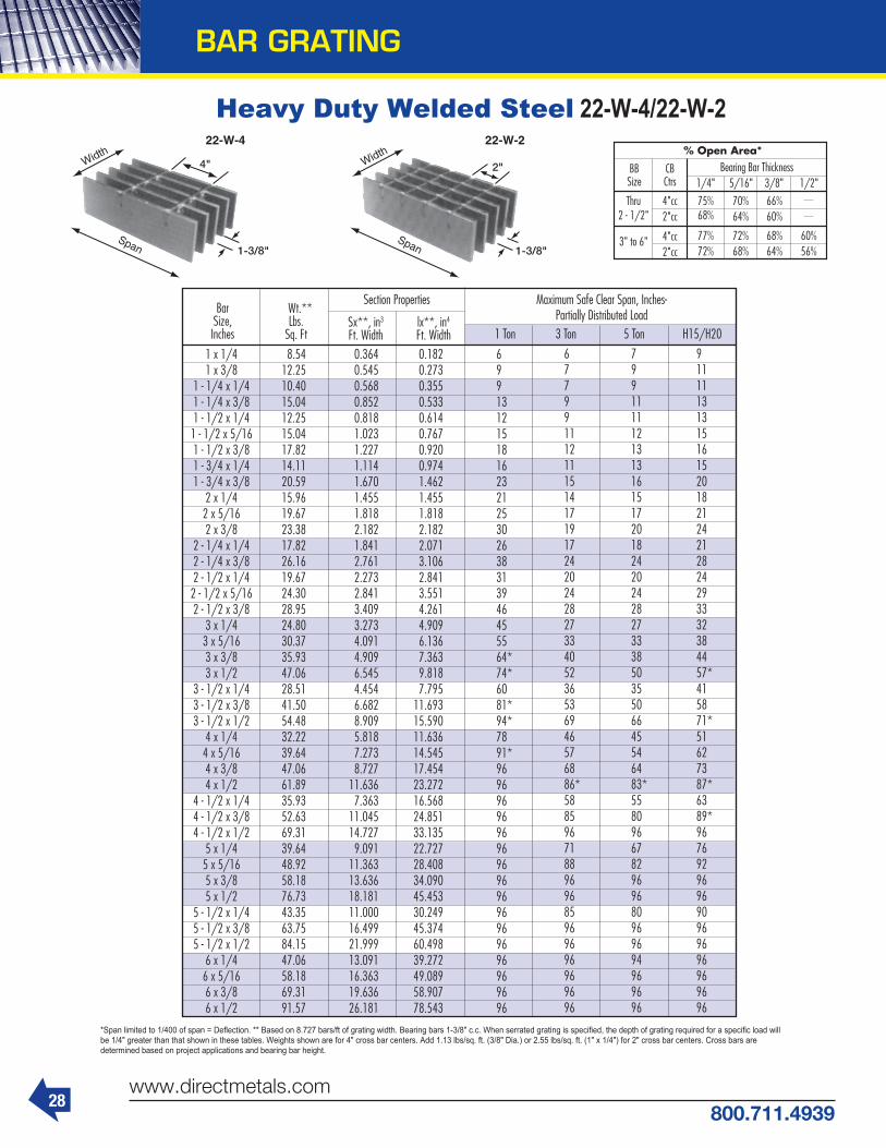
28www.directmetals.com
800.711.4939
BAR GRATING
Heavy Duty Welded Steel 22-W-4/22-W-2
1 x 1/41 x 3/8
1 - 1/4 x 1/41 - 1/4 x 3/81 - 1/2 x 1/41 - 1/2 x 5/161 - 1/2 x 3/81 - 3/4 x 1/41 - 3/4 x 3/8
2 x 1/42 x 5/162 x 3/8
2 - 1/4 x 1/42 - 1/4 x 3/82 - 1/2 x 1/42 - 1/2 x 5/162 - 1/2 x 3/8
3 x 1/43 x 5/163 x 3/83 x 1/2
3 - 1/2 x 1/43 - 1/2 x 3/83 - 1/2 x 1/2
4 x 1/44 x 5/164 x 3/84 x 1/2
4 - 1/2 x 1/44 - 1/2 x 3/84 - 1/2 x 1/2
5 x 1/45 x 5/165 x 3/85 x 1/2
5 - 1/2 x 1/45 - 1/2 x 3/85 - 1/2 x 1/2
6 x 1/46 x 5/166 x 3/86 x 1/2
8.5412.2510.4015.0412.2515.0417.8214.1120.5915.9619.6723.3817.8226.1619.6724.3028.9524.8030.3735.9347.0628.5141.5054.4832.2239.6447.0661.8935.9352.6369.3139.6448.9258.1876.7343.3563.7584.1547.0658.1869.3191.57
0.3640.5450.5680.8520.8181.0231.2271.1141.6701.4551.8182.1821.8412.7612.2732.8413.4093.2734.0914.9096.5454.4546.6828.9095.8187.2738.727
11.6367.363
11.04514.7279.091
11.36313.63618.18111.00016.49921.99913.09116.36319.63626.181
0.1820.2730.3550.5330.6140.7670.9200.9741.4621.4551.8182.1822.0713.1062.8413.5514.2614.9096.1367.3639.8187.795
11.69315.59011.63614.54517.45423.27216.56824.85133.13522.72728.40834.09045.45330.24945.37460.49839.27249.08958.90778.543
6991312151816232125302638313946455564*74*6081*94*7891*96969696969696969696969696969696
677991112111514171917242024282733405236536946576886*5885967188969685969696969696
79911111213131615172018242024282733385035506645546483*5580966782969680969694969696
91111131315161520182124212824293332384457*415871*51627387*6389*967692969690969696969696
Bar Size,Inches
Wt.**Lbs.
Sq. FtSx**, in3
Ft. Widthlx**, in4
Ft. Width
Section Properties Maximum Safe Clear Span, Inches-Partially Distributed Load
1 Ton 3 Ton 5 Ton H15/H20
BBSize
Thru2 - 1/2"
4"cc2"cc
75%68%
70%64%
66%60%
77%72%
72%68%
68%64%
60%56%
4"cc2"cc
3" to 6"
CBCtrs 1/4" 5/16" 3/8" 1/2"
Bearing Bar Thickness% Open Area*
*Span limited to 1/400 of span = Deflection. ** Based on 8.727 bars/ft of grating width. Bearing bars 1-3/8" c.c. When serrated grating is specified, the depth of grating required for a specific load will be 1/4" greater than that shown in these tables. Weights shown are for 4" cross bar centers. Add 1.13 lbs/sq. ft. (3/8" Dia.) or 2.55 lbs/sq. ft. (1" x 1/4") for 2" cross bar centers. Cross bars aredetermined based on project applications and bearing bar height.

29800.711.4939
www.directmetals.com
BAR GRATING
Heavy Duty Welded Steel - 22 Space
24273633378756805453682081807427
111339700
1212014547122731840715153189402272721820272733272743633296934454759393387874848758180
1 x 1/41 x 3/8
1 - 1/4 x 1/41 - 1/4 x 3/81 - 1/2 x 1/41 - 1/2 x 5/161 - 1/2 x 3/81 - 3/4 x 1/41 - 3/4 x 3/8
2 x 1/42 x 5/162 x 3/8
2 - 1/4 x 1/42 - 1/4 x 3/82 - 1/2 x 1/42 - 1/2 x 5/162 - 1/2 x 3/8
3 x 1/43 x 5/163 x 3/83 x 1/2
3 - 1/2 x 1/43 - 1/2 x 3/83 - 1/2 x 1/2
4 x 1/44 x 5/164 x 3/84 x 1/2
4 - 1/2 x 1/44 - 1/2 x 3/84 - 1/2 x 1/2
5 x 1/45 x 5/165 x 3/85 x 1/2
5 - 1/2 x 1/45 - 1/2 x 3/85 - 1/2 x 1/2
6 x 1/46 x 5/166 x 3/86 x 1/2
1618242225243787363645475453495174226467808096988182
1227110102126271515114547181822181829089197962969839596258583232438787517163272449089
1213181718932840272734104090371355674850606072736137920375779470
113631091013637163632181714847222732969719393242432909038787245433681749090303033787745453
97114531515227221812728327229714453388048485819490973636061757690918728
1090913091174531187717819237571551519395232723102919635294533927224243303013636348483293334399758664349094363552363
809121112621893181822732727247637113233404048494091613650516313757672739091
10909145449898
1484919798129291616219393258581636224544327272020225251303024040224444366644888729091363624363658180
6931038108216231558194923372122318127713463415635075259433054116493623477929350
124678484
1272816970110821385316623221641402521038280511731621644259733463020952314274190324935311683740249869
94714201363170520451857278324253030363730684602378847355682545568188182
109087423
11137148489697
1212214545193931227218404245451515218938227273030218333274983666521818272723272743635
1212151618181650247421562693323327274090336742095050484960617273969665999899
131998619
1077512929172391090816363218181346816834202012693516296244433259119394242412909038787
1485222719402424290924553681303137884545436454556545872759398909
1187977579697
11636155159817
14727196361212115151181812424114667219992933217455218172618134908
22323347275534444132396749595950793353998099
1079970528816
10578141048925
13388178511101913773165282203813333199992666515868198342380131735
2526315737883637454654547272494974249899646480819697
129298181
12272163631010112626151512020112222183322444314546181812181829090
424263648485554169278311
110827012
10519140268658
10822129871731510476157132095112468155841870124934
61369204
1227375769469
11363151519167
137491833310909136361636321818
Bar Size,Inches
Maximum Safe Concentrated Load*, Lbs. - Clear Span
Loads are theoretical, and are based on a unit stress of 20,000 psi.
1'- 0" 1'- 6" 2'- 0" 2'- 6" 3'- 0" 3'- 6" 4'- 0" 4'- 6" 5'- 0" 5'- 6" 6'- 0" 8'- 0"7'- 0"
BBSize
Thru2 - 1/2"
4"cc2"cc
75%68%
70%64%
66%60%
77%72%
72%68%
68%64%
60%56%
4"cc2"cc
3" to 6"
CBCtrs 1/4" 5/16" 3/8" 1/2"
Bearing Bar Thickness% Open Area*
* Based on 8.727 bars/ft of grating width. Bearing bars 1-3/8" c.c. Note: When serrated grating is specified, the depth of grating required for a specific load will be 1/4" greater than that shown in these tables.

30www.directmetals.com
800.711.4939
BAR GRATING
Stair Treads
STANDARD TREAD WIDTHS AND END PLATE DIMENSIONS
*Table of widths based on 3/16" thick bearing bars and standard bar spacing 1-3/16" cc (1-1/8" face-to-face for riveted grating.)
SUGGESTED BEARING BAR SIZES*
*Maximum tread length based on 400-lb. concentrated load on nosing and 4 bearing bars at center of tread length. NOTE: Since a serrated connecting bar does not reduce the strength of the grating, R and AR series treads may always be selected from the “Plain” column.
NOTE: DIM, B = 2-1/4"for ALL aluminum treads.
NOTE: Refer to drawings above for A and B dimensions 5 6-3/16 6-1/4 6-11/16 6-3/8 2-1/2 1-3/4 2-1/4
6 7-3/8 7-7/16 8 7-1/4 4-1/2 1-3/4 2-1/4 7 8-9/16 8-5/8 9-5/16 8-3/4 4-1/2 1-3/4 2-1/4
8 9-3/4 9-13/16 10-5/8 9-15/16 7 1-3/4 2-1/4
9 10-15/16 11 11-15/16 11-1/8 7 1-3/4 2-1/4
10 12-1/8 12-3/16 13-1/4 12-3/8 7 1-3/4 2-1/4
W, SG, SGF SGI R, AR Plank Dimension 1 1-1/2 Series Series Series Series A 1-1/4 1-3/4
Dimension BEnd Plate Dimensions
Aluminum Treads
Width (includes nosing*) Number of Bearing Bars
1" x 3/16" 2'-4" 2'-2" 1" I-Bar / Plank 2'-6" 3/4" x 3/16" 2'-4" 1'-11" 1-1/4" x 3/16" 2'-10" 2'-7" 1-1/4" I-Bar / Plank 3'-0" 1" x 3/16" 3'-5" 2'-10" 1-1/2" x 3/16" 3'-6" 3'-2" 1-1/2" I-Bar / Plank 3'-6" 1-1/4" x 3/16" 4'-8" 4'-2" 1-3/4" x 3/16" 4'-3" 3'-10" 1-3/4" I-Bar / Plank 4'-5" 1-1/2" x 3/16" 5'-6" 5'-3"
Steel Treads
Max. Tread Length*
PlainW, R
SeriesSGI Series
Plank SeriesMaximum Tread
Length*SGF, SG, AR
Series SerratedMax. Tread Length*Plain Serrated
STAIR TREAD DETAILS

31800.711.4939
www.directmetals.com
BAR GRATING
Anchoring DevicesSADDLE CLIPA special bent-clip type fastener for removable bar grating panels available in aluminum, stainless steel, and galvanized steel. Clips only are supplied by the grating manufacturer. Other fasteningaccessories to be provided byothers. (Note: Cross bars may need to be snipped in the field to facili-tate placement of saddle clips.)
ANCHOR BLOCKAnchor blocks of 1/4" or 3/16" thick aluminum, or steel may be shop welded by the gratingmanufacturer and used to fasten permanent or removable grating panels. Anchor blocks arerecessed thus offering a trip-free surface.
PLANK CLIPA special friction fastener used in conjunction with plank grating and embedded grating frames. When plank is banded, clips are installed by the manufacturer.
COUNTERSUNK LANDFor close-mesh aluminum grating (7/16" bearing bar cen-ters) a countersunk land may be drilled by the grating manufac-turer for use with a 1/4" diameter TEK screw by others.
GRATING CLAMPA special friction fastener available in aluminum, stainless steel, and galvanized steel used in conjunction with bar grating and embedded grating frames. (Note: Cross bars may need to be snipped in the field to facilitate placement of grating clamps.)
Z CLIPThe most versatile clip anchor available is the Z Clip. These clips are especially helpful in holding down riveted grating. Z Clips are manufactured from stainless steel, and are available in 1" (1" and1-1/4" grating) 1-1/2" (1-1/2" and 1-3/4" grating) and 2" (2", 2-1/4" and 2-1/2" grating) with a pre-punched hole to accept a 1/4" bolt or TEK screw by others.
PLANK LUGA plank lug inserted and tack welded between flanges can serve as an anchor block for plank grating. TEK screw fastener by others.
TACK WELDA positive method for anchoring all permanently installed grating.
EXAMPLES OF FABRICATIONS

FIBERGLASS
32www.directmetals.com
800.711.4939
Fiberglass Grating Applications

33800.711.4939
www.directmetals.com
FIBERGLASS
Fiberglass Grating ProductsMOLDED FIBERGLASS GRATINGMolded fiberglass grating is a fiberglass-reinforced plastic (FRP) that combines fiberglass rovings with thermosetting resins to form a strong, one-piece molded panel. A 65%/35% resin to glass weight ratioprovides high corrosion resistance. Meniscus surfaces, or applied grit surfaces provide slip resistance when compared to other flooring prod-ucts. This product is better suited for corrosive environments.
PULTRUDED FIBERGLASS GRATINGPultruded fiberglass grating is made using premium gradeisophthalic polyester, vinyl ester or phenolic resin systems with asynthetic surfacing veil, making it corrosion resistant, lightweight, and durable. Pultruded fiberglass has a grit surface for safety, and a greater strength to weight ratio than molded fiberglass grating. A 35%/65% resin to glass ratio provides greater strength and lesscorrosion resistance than molded fiberglass. This product is better suited for longer spans.
FIBERGLASS COVERED GRATINGOur fiberglass covered grating is a long-lasting, molded fiberglass floor product that combines smooth, gritted or checker plate and molded grating manufactured with any of our resin systems. It is the ideal choice when a 100% covered flooring surface is needed. Ourfiberglass covered grating is often used in loading and storage areas with high foot and cart traffic, where a strong, level surface is ideal. It offers approximately 50% higher stiffness values than that of open mesh grating, and its standard grit-top cover assures secure footing.
BULLET RESISTANT FIBERGLASS PLATEOur bullet resistant fiberglass plate offers superior ballistic resistance at a weight less than 25% that of a comparable steel panel. Now avail-able for commercial security applications for your business, home or governmental facility, these fiberglass panels offer ballistic resistant security with the additional performance advantages of durability, cor-rosion resistance, electrical non-conductivity, low thermalconductivity and light weight.
HEAVY DUTY FIBERGLASS GRATINGOur heavy duty fiberglass grating is available in both molded and pultruded grating systems. Both are designed to carry forklift and trac-tor-trailer loads that traditional molded and pultruded FRPgrating products are not designed to support. Heavy duty fiberglass grating provides greater durability for higher volume traffic areas as well. Additionally, heavy duty fiberglass grating can be used to free span longer distances than traditional fiberglass grating
CUSTOM MATCHED COLORS AVAILABLEWill match to any RAL color.
FIBERGLASS STAIR TREADS & STAIR TREADCOVERSLightweight and easy to install, fiberglass stair treads are available in both molded and pultruded types, to match the fiberglass floorgrating platforms. Fiberglass stair tread covers are made from a molded glass and resin system that is corrosion and impact resistant, fire retardant, and non-conductive. They provide a cost effective,slip-resistant, protective surface for concrete, metal and wood steps.
FIBERGLASS GRATING HANDRAILS AND LADDERSFiberglass handrail systems are fabricated from pultruded fiberglass components and molded thermoplastic connectors. Our modular fiber-glass grating handrail systems are available in 2" square or2" round configurations that are easy to grip, making them ideal for any high traffic area. Our fiberglass ladders and cages can beinstalled in a variety of applications, from sumps to tanks, buildings, piers, portable equipment, etc., providing years of strength anddependability.
FIBERGLASS ATTACHMENTS AND CLIPSOur fiberglass grating attachments and clips are specially designed to secure fiberglass grating or plates to the supporting structures.Additionally, they are used to fasten together adjacent gratingpanels, which minimizes load-induced differential deflection. Allfiberglass attachments and clips are made of Type 316 stainless steel, and are available in 1", 1-1/2" and 2" sizes.
FIBERGLASS PLATESFiberglass plates feature a non-conductive surface that makes them an economical and safe solution to walking surfaces. In caustic and/or acidic conditions, fiberglass plates provide a level of corrosionresistance that is unequaled and more cost effective than stainless steel. Fiberglass plate is available with a non-grit surface, or with a grit surface where anti-slip traction is needed.
FIBERGLASS STRUCTURAL SHAPESOur fiberglass structural shapes and pultruded fiberglass profiles are made from a combination of fiberglass and thermosetting resinsystems. All shapes are lightweight, impact resistant, lowmaintenance, non-magnetic, low conductive, and have dimensional stability, making them easy to install and ideal for severalapplications. Custom shapes are available upon request.
Our Pultruded Grating Inventory
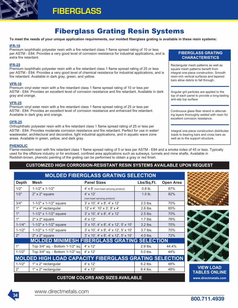
34www.directmetals.com
800.711.4939
FIBERGLASS
Fiberglass Grating Resin Systems
MOLDED FIBERGLASS GRATING SELECTIONDepth Mesh Panel Sizes Lbs/Sq.Ft. Open Area1/2" 1-1/2" x 1-1/2" 4' x 8' (non-load carrying product) 0.8 lb. 87%1/2" 2" x 2" square 4' x 12' 1.0 lb. 82% (non-load carrying product)
3/4" 1-1/2" x 1-1/2" square 3' x 10', 4' x 8', 4' x 12' 2.0 lbs. 70%1" 1" x 4" rectangular 12' x 4', 10' x 3', 8' x 4' 2.6 lbs. 65%1" 1-1/2" x 1-1/2" square 3' x 10', 4' x 8', 4' x 12' 2.5 lbs. 70%1" 2" x 2" square 4' x 12' 1.7 lbs. 76%1-1/4" 1-1/2" x 1-1/2" square 3' x 10', 4' x 8', 4' x 12', 5' x 10' 3.2 lbs. 70%1-1/2" 1-1/2" x 1-1/2" square 3' x 10', 4' x 8', 4' x 12', 5' x 10' 3.7 lbs. 70%2" 2" x 2" square 3' x 10', 4' x 8', 4' x 12', 5' x 10' 4.0 lbs. 72%
CUSTOMIZED HIGH CORROSION-RESISTANT RESIN SYSTEMS AVAILABLE UPON REQUEST
To meet the needs of your unique application requirements, our molded fiberglass grating is available in these resin systems:
IFR-10Premium isophthalic polyester resin with a fire retardant class 1 flame spread rating of 10 or lessper ASTM - E84. Provides a very good level of corrosion resistance for industrial applications, and isextra fire retardant.
IFR-25Premium isophthalic polyester resin with a fire retardant class 1 flame spread rating of 25 or lessper ASTM - E84. Provides a very good level of chemical resistance for industrial applications, and is fire retardant. Available in dark gray, green, and yellow.
VFR-10Premium vinyl ester resin with a fire retardant class 1 flame spread rating of 10 or less perASTM - E84. Provides an excellent level of corrosion resistance and fire retardant. Available in dark gray and orange.
VFR-25Premium vinyl ester resin with a fire retardant class 1 flame spread rating of 25 or less perASTM - E84. Provides an excellent level of corrosion resistance and enhanced fire retardant.Available in dark gray and orange.
OFR-25Orthophthalic polyester resin with a fire retardant class 1 flame spread rating of 25 or less perASTM - E84. Provides moderate corrosion resistance and fire retardant. Perfect for use in water/wastewater, architectural and decorative, light industrial applications, and in aquatic wave zoneareas. Available in green, yellow, and dark gray.
PHENOLICFlame-resistant resin with fire retardant class 1 flame spread rating of 5 or less per ASTM - E84 and a smoke index of 45 or less. Typically used for the offshore industry or for enclosed, confined area applications such as subways, tunnels and mine shafts. Available inReddish-brown, phenolic painting of the grating can be performed to obtain a gray or red finish.
MOLDED HIGH LOAD CAPACITY FIBERGLASS GRATING SELECTION
1" Top 3/4" sq. - Bottom 1-1/2" sq. 4' x 12' 2.9 lbs. 44.4%1-1/2" Top 3/4" sq. - Bottom 1-1/2" sq. 4' x 12' 5.0 lbs. 44%
1-1/2" 1" x 2" rectangular 4' x 12' 6.2 lbs. 48%2" 1" x 2" rectangular 4' x 12' 8.4 lbs. 48% VIEW LOAD
TABLES ONLINEwww.directmetals.com
Rectangular mesh patterns as well as square mesh patterns benefit fromintegral one-piece construction. Smooth resin-rich vertical surfaces and tapered bars allow debris to fall through.
Continuous glass fiber strand in alternat-ing layers thoroughly wetted with resin for excellent corrosion resistance.
Integral one-piece construction distributes loads to bearing bars and cross bars as well as to the support structure.
Angular grit particles are applied to the top of each panel to provide a long-lasting anti-slip top surface
FIBERGLASS GRATINGCHARACTERISTICS
CUSTOM COLORS AND SIZES AVAILABLE
MOLDED MINIMESH FIBERGLASS GRATING SELECTION

35800.711.4939
www.directmetals.com
FIBERGLASS
Molded Grating Details
1-1/2" X .75" SQUARE MINIMESHTHICKNESS: 1 INCHMesh Pattern: 1-1/2" x .75" SquareOpen Area: 43%Weight: 2.9 Lbs/Sq. FootBar Width: 1/4 InchBars/Foot: 8
1-1/2" X 1-1/2" SQUARETHICKNESS: 1 INCHMesh Pattern: 1-1/2" SquareOpen Area: 68%Weight: 2.5 Lbs/Sq. FootBar Width: 1/4 InchBars/Foot: 8
1" X 4" RECTANGULARTHICKNESS: 1 INCHMesh Pattern: 1" x 4" RectangularOpen Area: 67%Weight: 2.6 Lbs/Sq. FootBar Width: 1/4 InchBars/Foot: 12
1-1/2" X .75" SQUARE MINIMESHTHICKNESS: 1-1/2 INCHMesh Pattern: 1-1/2" x .75" SquareOpen Area: 43%Weight: 4.5 Lbs/Sq. FootBar Width: 1/4 InchBars/Foot: 8
1-1/2" X 1-1/2" SQUARETHICKNESS: 1-1/2 INCHMesh Pattern: 1-1/2" SquareOpen Area: 68%Weight: 3.8 Lbs/Sq. FootBar Width: 1/4 InchBars/Foot: 8
2" X 2" SQUARETHICKNESS: 2 INCHMesh Pattern: 2" SquareOpen Area: 71%Weight: 4.0 Lbs/Sq. FootBar Width: 1/4 InchBars/Foot: 6

36www.directmetals.com
800.711.4939
Pultruded Grating
All of our pultruded gratings are manufac-tured with a high percentage of glasswithin the laminate, providing durability, extremely high unidirectional strength, and stiffness. Due to its exceptional stiffness, it can be used with confidence in applica-tions where wide support spans arerequired. For most applications where it is used to replace corroding steel grating, our pultruded grating rarely requiresadditional support.
Designed specifically for pedestrian walk-ways, our pedestrian floor grating is ideal
for any application where a corrosion-re-sistant, durable, lightweight surfacematerial is required. Our pedestrian grating is available in 1" and 1-1/2" depths and in several configurations and panel sizes. 1" deep pedestrian grating is designedfor access areas and walkways where pedestrian traffic is the heaviest load. 1-1/2" pedestrian grating is approximately three times stiffer than the 1" deep version and is used for applications where wider spans (up to 72") or lower deflectioncriteria are required.
To form a pultruded element, continuous fiber rovings and mat are mechanically drawn through a resin bath and shaped through a series of forming guides, then pulled through a heated die.
LIGHTWEIGHT YET DURABLE - less than one-half the weight of steel grating,allowing easy removal for access below floor level and installation with no heavy equipment and less manpower required.
ADDED SAFETY - durable grit surface,permanently bonded, and baked to thegrating surface, for a safe, slip-resistant walkway.
FIRE RETARDANT - flame spread rating of 25 or less, according to ASTM E-84; meets the self-extinguishing requirements of ASTM D-635.
MAINTENANCE FREE - corrosion resis-tant and requires no scraping, sandblast-ing or painting; install it and forget it.
UV PROTECTION - UV inhibitors included in the resin formulation, along with a sur-facing veil and grit top surface for optimum protection from the effects of weathering.
EASILY FABRICATED - no need for lift-ing equipment or expensive tools; can beeasily carried by two workers and cut using standard circular or saber sawsfitted with carbide blades.
ELECTRICALLY AND THERMALLY NON-CONDUCTIVE - providing additionalworker safety.
ELECTRONICALLY TRANSPARENT - does not affect electromagnetic or radio wave frequencies.
Combining corrosion resistance, long life, and a maintenance-free design, our pul-truded grating is superior to conventional metals. This advanced grating is also light-weight and easy to fabricate, making it less expensive to install. In fact, the savings on labor and equipment often make the total installed cost of our pultruded gratingcomparable to that of steel. Combining it’s low cost of installation with main-tenance-free long-life, it is manufactured with a recessed tie bar configuration and an inherent resiliency, which reduces back and leg strain and contributes toergonomics and worker productivity.
FEATURES AND BENEFITS
CORROSION RESISTANCE - based on the use of premium grade, isophthalic polyester or vinyl ester resin systems and a synthetic surfacing veil.
Series Panel Depth Load Bar Spacing Sizes Load Bars/Ft. Wt./Sq.Ft. Open Area Width Length
I-6010 1" 1-1/2" 2', 3', 4' 10', 12', 20', 24' 8 2.4 lbs. 60% I-4010 1" 1" 2', 3', 4' 10', 12', 20', 24' 12 3.4 lbs. 40% I-6015 1-1/2" 1-1/2" 2', 3', 4' 10', 12', 20', 24' 8 2.8 lbs. 60% I-4015 1-1/2" 1" 2', 3', 4' 10', 12', 20', 24' 12 4.1 lbs. 40% T-5020 2" 2" 2', 3', 4' 10', 12', 20', 24' 6 3.1 lbs. 50% T-3320 2" 1-1/2" 2', 3', 4' 10', 12', 20', 24' 8 4.0 lbs. 33%
SELECTION OF PULTRUDED INDUSTRIAL GRATING - 6" TIE BAR SPACING STANDARD
Series Panel Depth Load Bar Spacing Sizes Load Bars/Ft. Wt./Sq.Ft. Open Area Width Length
T-3810 1" 2.4" 2', 3', 4' 10', 12', 20', 24' 5 1.9 lbs. 38% T-2510 1" 2.0" 2', 3', 4' 10', 12', 20', 24' 6 2.3 lbs. 25% T-1210 1" 1.7" 2', 3', 4' 10', 12', 20', 24' 7 2.7 lbs. 12% T-3815 1-1/2" 2.4" 2', 3', 4' 10', 12', 20', 24' 5 2.7 lbs. 38% T-2515 1-1/2" 2.0" 2', 3', 4' 10', 12', 20', 24' 6 3.2 lbs. 25% T-1215 1-1/2" 1.7" 2', 3', 4' 10', 12', 20', 24' 7 3.6 lbs. 12%
SELECTION OF PULTRUDED PEDESTRIAN GRATING - 6" TIE BAR SPACING STANDARD
VIEW SPEC TABLES ONLINEwww.directmetals.com
FIBERGLASS

37800.711.4939
www.directmetals.com
FIBERGLASS
Pultruded Grating Details1" DEEP I-6010 GRATINGBar Height: 1"Open Area: 60%Weight: 2.72 Lbs/Sq. FootBar Width: 0.6"Bars/Foot: 8Cross Bars: 6" Centers Std. (12" Special Order)
1" DEEP I-4010 GRATINGBar Height: 1"Open Area: 40%Weight: 3.41 Lbs/Sq. FootBar Width: .600"Bars/Foot: 12Cross Bars: 6" Centers Std.
1-1/2" I-4015 GRATINGBar Height: 1.50"Open Area: 40%Weight: 4.13 Lbs/Sq. FootBar Width: .600"Bars/Foot: 12Cross Bars: 6" Centers Std.
2" T-5020 GRATINGBar Height: 2"Open Area: 50%Weight: 3.10 Lbs/Sq. FootBar Width: 1"Bars/Foot: 6Cross Bars: 6" Centers Std.
1-1/2" DEEP I-6015 GRATINGBar Height: 1.50"Open Area: 60%Weight: 2.83 Lbs/Sq. FootBar Width: .600"Bars/Foot: 8Cross Bars: 6" Centers Std.
2" T-3320 GRATINGBar Height: 2"Open Area: 33%Weight: 4.00 Lbs/Sq. FootBar Width: 1.00"Bars/Foot: 8Cross Bars: 6" Centers Std.

38www.directmetals.com
800.711.4939
FIBERGLASS
Pultruded T-Bar Pedestrian Series Grating DetailsT1215 PEDESTRIAN GRATINGThickness: 1-1/2"Cross Bar: 6" CentersOpen Area: 12%Weight: 3.6 Lbs/Sq. FootBar Centers: 1.71"Bars/Foot: 7
T1210 PEDESTRIAN GRATINGThickness: 1"Cross Bar: 6" CentersOpen Area: 12%Weight: 2.6 Lbs/Sq. FootBar Centers: 1.71"Bars/Foot: 7
T3810 PEDESTRIAN GRATINGThickness: 1"Cross Bar: 6" CentersOpen Area: 38%Weight: 1.9 Lbs/Sq. FootBar Centers: 2.4"Bars/Foot: 5
T3815 PEDESTRIAN GRATINGThickness: 1-1/2"Cross Bar: 6" CentersOpen Area: 38%Weight: 2.7 Lbs/Sq. FootBar Centers: 2.4"Bars/Foot: 5

39800.711.4939
www.directmetals.com
FIBERGLASS
Molded Heavy Duty Grating Details1-1/2" DEEP X 1" X 2" RECTANGULARLoad Bar Depth: 1"Open Area: 48%Weight: 6.2 Lbs/Sq. FootBar Width: 0.43"Bars/Foot: 12
2" DEEP X 1" X 2" RECTANGULARLoad Bar Depth: 1"Open Area: 48%Weight: 8.4 Lbs/Sq. FootBar Width: 0.48"Bars/Foot: 12
APPLICATIONS• Amusement/water parks• Hotels/motels• Outdoor stairways• Outdoor sports facilities• Restaurants• Food processing facilities• Chemical processing plants• Water/wastewater treatment facilities
Fiberglass Stair Treads & Covers
Material Molded Polyester or Vinyl Ester
Resin IFR-25/VFR-25
Surface Grit
Mesh 1-1/2" x 6"
% O/A 67%
Height 1-1/2"
Depths 7-5/8", 9-1/8", 10-5/8", 12-1/4"
Widths Cut-to-size
FIBERGLASS MOLDEDSTAIR TREADS
IMPORTANT FEATURES OF STAIR TREADS & STAIR TREAD COVERS
• Corrosion resistant • Slip resistant • High impact resistant • Durable • Low maintenance • Fire retardant • Lightweight • Easy to install • Non-conductive
Safety and durability are just two of many out-standing features that make fiberglass stair treads and stair tread covers preferred compo-nents for stairs and landings. Maximum pedes-trian safety is provided by the anti-slip walking surface. Fiberglass stair nosings form a highly visible and durable edge at the primary point of contact on stairs and landings. Fiberglass stair treads and stair tread covers provide a cost-effective, slip-resistant protective surface for concrete, metal, and wood steps.
Stair tread covers are made from a molded polyester mat that is corrosion and impact resistant, fire retardant, and non-conductive. Stair treads come in 8-, 9-, 10-, 11- and 12-inch depths, with a standard thickness of 1/8 inch with 1/4-inch thick covers available for heavy duty applications. Standard 12-foot stair treads are easily cut to size during installation, or are available precut to custom lengths.
Fiberglass stair tread covers have a durable aluminum oxide grit surface, which increases the safety of stairways, and protects exposed edges that are prone to chipping and cracking.
Lightweight and easy to install, industrial grade fiberglass stair treads are available in 1-inch and 1-1/2-inch deep “I” bar struc-tural profiles with a variable open area of 40%, 50% or 60%. We also carry 2-inch deep “T” bar structural profiles with 33% or 50% open area. Stair tread covers are black or dark gray with highly visible yellow nosings, and are available in 9- and 10-inch widths by 12-foot lengths.

40www.directmetals.com
800.711.4939
Pultruded Grating Resin SystemsOur ASTM E84 pultruded grating is available in two resin formulations for an accurate match of product characteristics with the applica-tion. Both resin systems provide corrosion resistance that is superior to that offered by metal grating.
IFR-25 - This isophthalic polyester resin formulation provides a low flame spread rating of 25 or less, and is designed for applicationswhere there is moderate exposure to corrosive elements.
VFR-25 - With a flame spread of 25 or less, this vinyl ester resin system provides dependable resistance to both acidic and alkalineenvironments.
CLIP ASSEMBLIES FOR MOLDED GRATING
We offer specially-designed attachments and clips, both to fasten panels together and to secure them to support structures. All types are made of Type 316 Stainless Steel, and are available in 1", 1-1/2" and 2" sizes. Install clips a maximum of every 48", and use at least four clips per piece of grating (at least eight clips per 4' x 12' panel)
RESIN SERIES STANDARD COLOR IFR-25 & VFR-25 T3810, T2510, T3815, T2515 YELLOW & DARK GRAY IFR-25 & VFR-25 T1210, T1215 LIGHT GRAY IFR-25 & VFR-25 I6010, I6015, I4010, I4015, T3320, T5020 YELLOW & DARK GRAY VFR-25 H4710, H4715, H4720, H4725, H4730 YELLOW & DARK GRAY
FIBERGLASS
TYPE Z HOLD DOWN CLIPS:Secure grating panelsto support frames.
TYPE F END PANEL CLIPS:Provide a simplified method for joining factory edges of adjacent abutting panels. (Not for use with some resins)
TYPE G HOLD DOWN CLIPS:Attach grating to any structural member flange, 3/4" or smaller in thickness, with no drilling required.
TYPE M HOLD DOWN CLIPS:Secure panels to a support in the same manner as type J Clips, but designed to use two adjacent grating bars for a more secure fit. Similar in design to metal gratingsaddle clips.
Field cutting of one bar required
CLIP ASSEMBLIES FOR PULTRUDED GRATING
We offer Hold Down Clip Assemblies for many pultruded grating typesCLIP TYPE• P18 for 18% open area pultruded grating• P25 for 25% open area pultruded grating• P33 for 33% open area pultruded grating• P40 for 40% open area pultruded grating• P50 for 50% open area pultruded grating• P60 for 60% open area pultruded grating
SEALING KITSTo maintain corrosion resistance and structural integrity, we offer standard resin sealing kits for protecting theexposed ends of cut panels and other components.
TYPE P

41800.711.4939
www.directmetals.com
EXPANDED METAL
REGULAR EXPANDED METAL
FLATTENED EXPANDED METAL SHEARING
Regular Expanded Metal is a finished product, as it comes from the press after having been die cut and expanded. Illustration shows that the strands and bonds form a sharp angle to the original plane of the solid sheet.
Flattened Expanded Metal is regularexpanded metal, which has been cold rolled, leaving a flat, smooth surface.
SIDE SHEARINGThe process of cutting a piece ofexpanded metal parallel to the longdimension of the diamond.
Random Side Shearing - Side shearing is a cut made parallel to the LWD dimension of the sheet, which usually leaves open diamonds. Flat expanded metal SWD shearing tolerance is plus or minus 1/8" when both sides are sheared.
Bond Side Shearing - This cut is made along the length of the sheet on the center line of the bond over the specified width. In most cases, it is not practical to attempt to Bond Side Shear either regular or flattened expanded metalbecause of camber.
END SHEARINGThe process of cutting a piece of expanded metal parallel to the short way of the diamond.
End Random Shearing - The process of shearing a piece of expanded metal to a specified length (LWD). This cut normally leaves open diamonds at both ends, but accomplishes close tolerance (plus or minus 1/8") when both ends of flatexpanded metal are sheared.
End Bond Shearing - The process of shearing a piece of expanded metal to a specified length (LWD). A plus or minus 1/8" tolerance applies when both ends of flat expanded metal are sheared. One end is cut on the Bond parallel to the SWD, the other end usually has open diamonds.NOTE: When end bond shearing isrequested for both ends of flat expanded metal, the sheet is sheared at the center line of the bond over the specified length. A tolerance minus 0 plus 1/2" diamondapplies. It is possible to end bond shear, but extraordinary care must be exercised to maintain the squareness of the sheet.
SQUARENESSWhen all four sides of a sheet of expanded metal are sheared, the maximum toler-ance will be plus or minus 1/16" per foot of width.
1/4" #20 Regular 1/4" #20 Flattened
1/2" #16 Regular 1/2" #16 Flattened
3/4" #13 Regular 3/4" #13 Flattened
1-1/2" #9 Regular 1-1/2" #9 Flattened
Patterns Shown Actual Size
SIDE BOND SHEARING
SID
E B
ON
D S
HEA
RIN
G
SID
E R
AN
DO
M S
HEA
RIN
G
SIDE RANDOM SHEARING
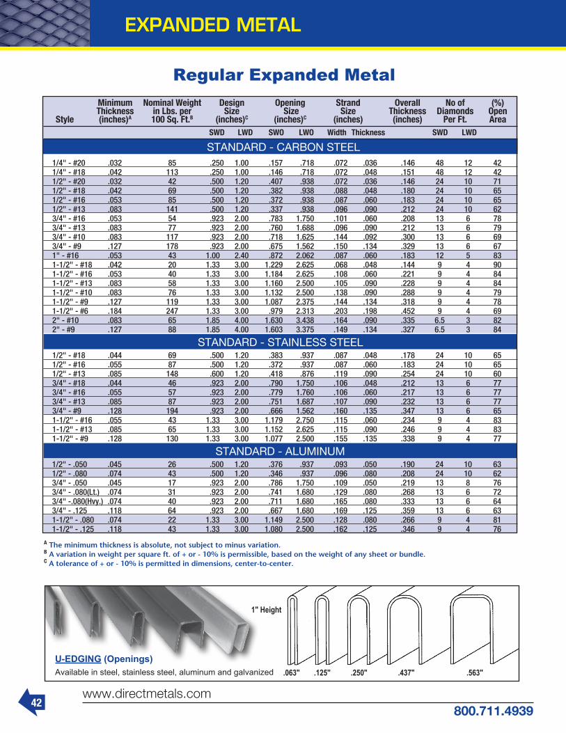
42www.directmetals.com
800.711.4939
EXPANDED METAL
Regular Expanded Metal
.063" .125" .250" .437" .563"
1" Height
U-EDGING (Openings)Available in steel, stainless steel, aluminum and galvanized
Minimum Nominal Weight Design Opening Strand Overall No of (%) Thickness in Lbs. per Size Size Size Thickness Diamonds Open Style (inches)A 100 Sq. Ft.B (inches)C (inches)C (inches) (inches) Per Ft. Area SWD LWD SWO LWO Width Thickness SWD LWD
1/4" - #20 .032 85 .250 1.00 .157 .718 .072 .036 .146 48 12 42 1/4" - #18 .042 113 .250 1.00 .146 .718 .072 .048 .151 48 12 42 1/2" - #20 .032 42 .500 1.20 .407 .938 .072 .036 .146 24 10 71 1/2" - #18 .042 69 .500 1.20 .382 .938 .088 .048 .180 24 10 65 1/2" - #16 .053 85 .500 1.20 .372 .938 .087 .060 .183 24 10 65 1/2" - #13 .083 141 .500 1.20 .337 .938 .096 .090 .212 24 10 62 3/4" - #16 .053 54 .923 2.00 .783 1.750 .101 .060 .208 13 6 78 3/4" - #13 .083 77 .923 2.00 .760 1.688 .096 .090 .212 13 6 79 3/4" - #10 .083 117 .923 2.00 .718 1.625 .144 .092 .300 13 6 69 3/4" - #9 .127 178 .923 2.00 .675 1.562 .150 .134 .329 13 6 67 1" - #16 .053 43 1.00 2.40 .872 2.062 .087 .060 .183 12 5 83 1-1/2" - #18 .042 20 1.33 3.00 1.229 2.625 .068 .048 .144 9 4 90 1-1/2" - #16 .053 40 1.33 3.00 1.184 2.625 .108 .060 .221 9 4 84 1-1/2" - #13 .083 58 1.33 3.00 1.160 2.500 .105 .090 .228 9 4 84 1-1/2" - #10 .083 76 1.33 3.00 1.132 2.500 .138 .090 .288 9 4 79 1-1/2" - #9 .127 119 1.33 3.00 1.087 2.375 .144 .134 .318 9 4 78 1-1/2" - #6 .184 247 1.33 3.00 .979 2.313 .203 .198 .452 9 4 69 2" - #10 .083 65 1.85 4.00 1.630 3.438 .164 .090 .335 6.5 3 82 2" - #9 .127 88 1.85 4.00 1.603 3.375 .149 .134 .327 6.5 3 84
A The minimum thickness is absolute, not subject to minus variation.B A variation in weight per square ft. of + or - 10% is permissible, based on the weight of any sheet or bundle.C A tolerance of + or - 10% is permitted in dimensions, center-to-center.
STANDARD - CARBON STEEL
1/2" - #18 .044 69 .500 1.20 .383 .937 .087 .048 .178 24 10 65 1/2" - #16 .055 87 .500 1.20 .372 .937 .087 .060 .183 24 10 65 1/2" - #13 .085 148 .600 1.20 .418 .876 .119 .090 .254 24 10 60 3/4" - #18 .044 46 .923 2.00 .790 1.750 .106 .048 .212 13 6 77 3/4" - #16 .055 57 .923 2.00 .779 1.760 .106 .060 .217 13 6 77 3/4" - #13 .085 87 .923 2.00 .751 1.687 .107 .090 .232 13 6 77 3/4" - #9 .128 194 .923 2.00 .666 1.562 .160 .135 .347 13 6 65 1-1/2" - #16 .055 43 1.33 3.00 1.179 2.750 .115 .060 .234 9 4 83 1-1/2" - #13 .085 65 1.33 3.00 1.152 2.625 .115 .090 .246 9 4 83 1-1/2" - #9 .128 130 1.33 3.00 1.077 2.500 .155 .135 .338 9 4 77
STANDARD - STAINLESS STEEL
1/2" - .050 .045 26 .500 1.20 .376 .937 .093 .050 .190 24 10 63 1/2" - .080 .074 43 .500 1.20 .346 .937 .096 .080 .208 24 10 62 3/4" - .050 .045 17 .923 2.00 .786 1.750 .109 .050 .219 13 8 76 3/4" - .080(Lt.) .074 31 .923 2.00 .741 1.680 .129 .080 .268 13 6 72 3/4" -.080(Hvy.) .074 40 .923 2.00 .711 1.680 .165 .080 .333 13 6 64 3/4" - .125 .118 64 .923 2.00 .667 1.680 .169 .125 .359 13 6 63 1-1/2" - .080 .074 22 1.33 3.00 1.149 2.500 .128 .080 .266 9 4 81 1-1/2" - .125 .118 43 1.33 3.00 1.080 2.500 .162 .125 .346 9 4 76
STANDARD - ALUMINUM

43800.711.4939
www.directmetals.com
Flattened Expanded Metal & Grating
EXPANDED METAL
A Th
e m
inim
um t
hic
knes
s is
ab
solu
te, n
ot s
ubje
ct t
o m
inus
var
iati
on.
B A v
aria
tion
in w
eig
ht
per
sq
uare
ft.
of
+ or
- 1
0% is
per
mis
sib
le, b
ased
on
th
e w
eig
ht
of a
ny
shee
t or
bun
dle
.C A
tol
eran
ce o
f +
or -
10%
is p
erm
itte
d in
dim
ensi
ons,
cen
ter-
to-c
ente
r.
Minimum Nominal Weight Design Opening Strand Overall No of (%) Thickness in Lbs. per Size Size Size Thickness Diamonds Open Style (inches)A 100 Sq. Ft.B (inches)C (inches)C (inches) (inches) Per Ft. Area SWD LWD SWO LWO Width Thickness SWD LWD
1/4" - #20 .026 74 .250 1.05 .092 .715 .079 .029 .029 48 11.6 37 1/4" - #18 .034 100 .250 1.05 .090 .715 .080 .038 .038 48 11.6 36 1/2" - #20 .026 37 .500 1.26 .342 1.000 .079 .029 .029 24 9.5 68 1/2" - #18 .034 61 .500 1.26 .306 1.000 .097 .038 .038 24 9.6 61 1/2" - #16 .043 77 .500 1.26 .304 1.000 .098 .048 .048 24 9.5 61 1/2" - #13 .066 126 .500 1.26 .286 1.000 .107 .072 .072 24 9.5 57 3/4" - #16 .043 47 .923 2.10 .701 1.750 .111 .048 .048 13 5.7 76 3/4" - #14 .054 56 .923 2.10 .713 1.760 .105 .060 .060 13 5.7 77 3/4" - #13 .066 67 .923 2.10 .711 1.781 .106 .072 .072 13 5.7 77 3/4" - #10 .066 102 .923 2.10 .603 1.755 .160 .072 .072 13 5.7 65 3/4" - #9 .101 157 .923 2.10 .593 1.688 .165 .108 .108 13 5.7 64 1" - #16 .043 38 1.000 2.52 .804 2.250 .098 .048 .048 12 4.684 80 1-1/2" - #16 .043 35 1.330 3.15 1.092 2.750 .119 .048 .048 9 3.75 82 1-1/2" - #14 .054 43 1.330 3.15 1.098 2.750 .116 .060 .060 9 3.75 83 1-1/2" - #13 .066 51 1.330 3.15 1.098 2.750 .116 .072 .072 9 3.76 83 1-1/2" - #9 .101 105 1.330 3.15 1.104 2.563 .158 .108 .108 9 3.75 76
STANDARD - CARBON STEEL
1/2" - #18 .037 66 .500 1.26 .304 1.000 .098 .041 .041 24 9.5 61 1/2" - #16 .047 84 .500 1.26 .302 1.000 .099 .051 .051 24 9.5 60 1/2" - #13 .072 168 .500 1.26 .236 .915 .132 .076 .076 24 9.5 47 3/4" - #18 .037 43 .923 2.10 .687 1.812 .118 .041 .041 13 5.7 74 3/4" - #16 .047 54 .923 2.10 .687 1.812 .118 .051 .051 13 5.7 74 3/4" - #13 .072 83 .923 2.10 .683 1.750 .120 .076 .076 13 5.7 74 3/4" - #9 .108 170 .923 2.10 .593 1.687 .165 .114 .114 13 5.7 64 1-1/2" - #16 .047 41 1.33 3.15 1.074 2.750 .128 .051 .051 9 3.8 81 1-1/2" - #13 .072 62 1.33 3.15 1.070 2.625 .130 .076 .076 9 3.8 80 1-1/2" - #9 .108 132 1.33 3.15 .960 2.625 .185 .114 .114 9 3.8 72
FLATTENED - STAINLESS STEEL
1/2" - .050 .034 22 .500 1.26 .292 1.000 .104 .038 .038 24 9.5 58 1/2" - .080 .056 35 .500 1.26 .290 1.000 .105 .060 .060 24 9.5 58 3/4" - .050 .034 14 .923 2.10 .679 1.812 .122 .038 .038 13 5.66 74 3/4" - .080(Lt.) .056 26 .923 2.10 .637 1.750 .143 .060 .060 13 5.66 69 3/4" -.080(Hvy.) .056 33 .923 2.10 .561 1.750 .181 .060 .060 13 5.66 61 3/4" - .125 .089 53 .923 2.10 .549 1.750 .187 .094 .094 13 5.66 59 1-1/2" - .080 .056 18 1.33 3.15 1.044 2.750 .143 .060 .060 9 3.8 78 1-1/2" - .125 .089 36 1.33 3.15 .968 2.750 .181 .094 .094 9 3.8 73
FLATTENED - ALUMINUM
Nominal Weight Design Opening Strand Overall No of (%) in Lbs. per Size Size Size Thickness Diamonds Open Style 100 Sq. Ft.A (inches)B (inches)B (inches) (inches) Per Ft. Area SWD LWD SWO LWO Width Thickness SWD LWD
2.0 lb. 2.00 1.33 5.33 1.000 3.60 .235 .135 .460 9 2.25 77 3.0 lb. 3.00 1.33 5.33 .940 3.44 .264 .183 .540 9 2.25 60 3.14 lb. 3.14 2.00 6.00 1.625 4.88 .312 .250 .656 6 2.00 69 4.00 lb. 4.00 1.33 5.33 .940 3.44 .300 .215 .618 9 2.25 55 4.27 lb. 4.27 1.41 4.00 1.000 2.88 .300 .250 .625 8.5 3.00 58 5.00 lb. 5.00 1.33 5.33 .813 3.38 .331 .250 .655 9 2.25 50 6.25 lb. 6.25 1.41 5.33 .813 3.38 .350 .312 .715 8.5 2.25 50 7.00 lb. 7.00 1.41 5.33 .813 3.38 .391 .318 .740 8.5 2.25 45
3.30 lb. 3.32 2.00 6.00 1.625 4.88 .312 .250 .656 6 2.00 69 4.50 lb. 4.25 1.41 4.00 1.000 2.88 .300 .250 .625 8.5 3.00 58
GRATING - CARBON STEEL
GRATING - STAINLESS STEEL
2.00 lb. 2.00 1.33 5.33 .940 3.44 .387 .250 .730 9 2.25 48GRATING - ALUMINUM
A A v
aria
tion
in w
eig
ht
per
sq
uare
ft.
of
+ or
- 5
% is
p
erm
issi
ble
, bas
ed o
n t
he
wei
gh
t of
an
y sh
eet
or b
und
le.
B A t
oler
ance
of
+ or
- 5
% is
per
mit
ted
in d
imen
sion
s,
cen
ter-
to-c
ente
r.
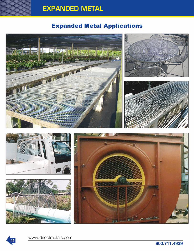
44www.directmetals.com
800.711.4939
EXPANDED METAL
Expanded Metal Applications

45800.711.4939
www.directmetals.com
TerminologyCALENDERING - A rolling operation which flattens the knuckles of wire cloth, giving it a smoother surface.
CRIMP - Undulations in warp and fill wires, which hold each other in place.
FILL WIRE - AKA shute wire, wirerunning across the width of the cloth.
FILTER CLOTH - Cloth used for flattening or straining (primarily plain and twilled dutch wire cloth and certain specifications of square mesh and off-count standard wire cloth).
HARDWARE CLOTH - Plain weave square mesh cloth of relatively light wire galvanized after weaving (usually between 2 to 8 openings per lineal inch).
MARKET GRADE - Applies to wire cloth specifications, most commonly used for general work. Market grade cloth is made of one size wire for each size closed mesh.
MESH - Number of openings per lineal inch, measured from center of wire tocenter of wire.
MICRON - 1/1000 millimeter, 0.00003937 inch. The unit of measure for particle retention of filter media.
OIL TEMPERED WIRE - High carbon steel wire that is heat resistant to produce good strength and abrasion resistance.
OPENING - Dimension between parallel adjacent wires. RECTANGULAR MESH - Wire cloth with different warp and fill wire mesh counts, which results in rectangular openings. The most common have a higher warp mesh than filter mesh. Advantages are increased open area, and reduced cost. SELVAGE - The finished edges of wire cloth running the length of the roll, which are produced by the weaving operation.
SPACE CLOTH - Wire cloth specified by the opening size, rather than by the mesh count.
SQUARE MESH - Mesh with equal spac-ing of warp and shute to give squareopenings.
WARP WIRE - Foundation wires running parallel to the length of the cloth.
WEAVES - Pattern in which wires areinterwoven.
WIRE DIAMETER OR GAUGE - Diameter of wire used in weaving cloth.
2 MESH WIRE CLOTH(count from center to center of wires)
1/2 INCH OPENING WIRE CLOTH(clear space between wires)
PLAIN WEAVEWires are crimped in a zig-zag fashion, with wires intersecting at every available crimp or pocket.
INTERCRIMPWires are crimped in a zig-zag fashion, with intersections at every 3rd, 5th or 7th, etc., crimp or pocket.
LOCK CRIMPDistinct crimp or pocket at wire intersec-tion, with straight connecting sections of wire.
FLAT TOPTop surface of wires all lie in same plane.Irregular crimped surface on underside.
Approx. Washburn & Approx. Diameter Gauge & Moen Diameter Inches Wire No. Wire Gauge Decimal
WIRE CLOTH

46www.directmetals.com
800.711.4939
Stainless Steel Filters
WIRE CLOTH
Stainless Steel Filters in many configurations available.
Used in all kinds of filters, chemical, rubber and plastic productsas well as automobile, decoration, building construction, etc.

47800.711.4939
www.directmetals.com
WIRE CLOTH
• PVC coated mesh for industrial, cage, and marine applications
• Coating on welded wire can handle intensive use without stripping or peeling
• Protective PVC coating makes PVC wire last many years longer than an uncoated wire
• Stocked colors are black, yellow and gray
• Custom colors available
PVC Wire Mesh

48www.directmetals.com
800.711.4939
WIRE CLOTH
Square Mesh Wire Cloth Specifications
1 MESH .063" GALVANIZED WELDED 2 MESH .041" GALVANIZED WELDED
2 MESH .063" GALVANIZED WELDED 4 MESH .025" GALVANIZED WELDED
2 MESH .041" PVC WELDED 2 MESH .120" SS WOVEN

49800.711.4939
www.directmetals.com
Square Mesh Wire Cloth Specifications
4 MESH .047" SS WOVEN 6 MESH .035" SS WOVEN
6 MESH .063" SS WOVEN 8 MESH .028" SS WOVEN
8 MESH .035" SS WOVEN 10 MESH .025" SS WOVEN
10 MESH .035" SS WOVEN 12 MESH .028" SS WOVEN
WIRE CLOTH

50www.directmetals.com
800.711.4939
WIRE CLOTH
Square Mesh Wire Cloth Specifications
1-1/2" Opening.135 CS Intercrimp
4" Opening - .250 CS Intercrimp
3" Opening - .250 CS Lock Crimp
1" Opening.250 CS Lock
Crimp
2" Opening.162 CS Lock Crimp
2" Opening.375 CS Lock Crimp

51800.711.4939
www.directmetals.com
WIRE CLOTH
Square Mesh Wire Cloth StandardsSPECIFICATIONS

52www.directmetals.com
800.711.4939
WIRE CLOTH
4 1.000 13.06 64.0% 4 0.750 7.68 70.9% 4 0.688 6.53 72.8% 4 0.625 5.46 74.8% 4 0.563 4.47 76.9% 4 0.500 3.58 79.0% 4 0.438 2.77 81.3% 4 0.375 2.07 83.6% 4 0.313 1.45 86.0% 4 0.283 1.20 87.2% 4 0.263 1.04 88.0% 4 0.250 0.94 88.6% 3-3/4 1.000 13.77 62.3% 3-3/4 0.750 8.11 69.4% 3-3/4 0.688 6.90 71.4% 3-3/4 0.625 5.77 73.5% 3-3/4 0.563 4.74 75.7% 3-3/4 0.500 3.79 77.9% 3-3/4 0.438 2.94 80.2% 3-3/4 0.375 2.19 82.6% 3-3/4 0.313 1.54 85.2% 3-3/4 0.283 1.27 86.5% 3-3/4 0.263 1.11 87.3% 3-3/4 0.250 1.00 87.9% 3-1/2 1.000 14.57 60.5% 3-1/2 0.750 8.60 67.8% 3-1/2 0.688 7.32 69.9% 3-1/2 0.625 6.13 72.0% 3-1/2 0.563 5.03 74.3% 3-1/2 0.500 4.03 76.6% 3-1/2 0.438 3.13 79.0% 3-1/2 0.375 2.33 81.6% 3-1/2 0.313 1.65 84.3% 3-1/2 0.283 1.36 85.6% 3-1/2 0.263 1.18 86.5% 3-1/2 0.250 1.07 87.1% 3-1/2 0.225 0.87 88.3% 3-1/2 0.207 0.74 89.1% 3-1/4 1.000 15.47 58.5% 3-1/4 0.750 9.16 66.0% 3-1/4 0.688 7.80 68.1% 3-1/4 0.625 6.54 70.3% 3-1/4 0.563 5.37 72.6% 3-1/4 0.500 4.31 75.0% 3-1/4 0.438 3.35 77.6% 3-1/4 0.375 2.50 80.4% 3-1/4 0.313 1.76 83.2% 3-1/4 0.283 1.46 84.6% 3-1/4 0.263 1.26 85.6% 3-1/4 0.250 1.15 86.2% 3-1/4 0.225 0.93 87.5% 3-1/4 0.207 0.79 88.4% 3-1/4 0.192 0.69 89.2% 3 1.000 16.50 56.3% 3 0.750 9.79 64.0% 3 0.688 8.35 66.2% 3 0.625 7.00 68.5% 3 0.563 5.76 70.9% 3 0.500 4.62 73.5% 3 0.438 3.59 76.2% 3 0.375 2.68 79.0% 3 0.313 1.90 82.0% 3 0.283 1.57 83.5% 3 0.263 1.36 84.5% 3 0.250 1.23 85.2% 3 0.225 1.01 86.5% 3 0.207 0.86 87.5% 3 0.192 0.74 88.3% 3 0.177 0.63 89.2% 3 0.162 0.53 90.0% 2-3/4 1.000 17.67 53.7% 2-3/4 0.750 10.52 61.7% 2-3/4 0.688 8.98 64.0% 2-3/4 0.625 7.54 66.4% 2-3/4 0.563 6.20 68.9% 2-3/4 0.500 4.98 71.6% 2-3/4 0.438 3.88 74.4% 2-3/4 0.375 2.90 77.4% 2-3/4 0.313 2.05 80.6% 2-3/4 0.283 1.70 82.2% 2-3/4 0.263 1.48 83.3% 2-3/4 0.250 1.34 84.0% 2-3/4 0.225 1.09 85.4% 2-3/4 0.207 0.93 86.5% 2-3/4 0.192 0.80 87.4% 2-3/4 0.177 0.69 88.3% 2-3/4 0.162 0.58 89.2% 2-3/4 0.148 0.48 90.0%
Clear Diameter Steel Opening of Rod Weight of Space or Wire Pounds Open Inch Inch Per Sq. Ft. Area
2-1/2 1.000 19.02 51.0% 2-1/2 0.750 11.37 59.2% 2-1/2 0.688 9.71 61.5% 2-1/2 0.625 8.16 64.0% 2-1/2 0.563 6.72 66.6% 2-1/2 0.500 5.41 69.4% 2-1/2 0.438 4.22 72.4% 2-1/2 0.375 3.16 75.6% 2-1/2 0.313 2.24 79.0% 2-1/2 0.283 1.85 80.7% 2-1/2 0.263 1.61 81.9% 2-1/2 0.250 1.46 82.6% 2-1/2 0.225 1.19 84.2% 2-1/2 0.207 1.02 85.3% 2-1/2 0.192 0.88 86.2% 2-1/2 0.177 0.75 87.2% 2-1/2 0.162 0.63 88.2% 2-1/2 0.148 0.53 89.1% 2-1/4 1.000 20.61 47.9% 2-1/4 0.750 12.37 56.2% 2-1/4 0.688 10.58 58.7% 2-1/4 0.625 8.90 61.2% 2-1/4 0.563 7.34 64.0% 2-1/4 0.500 5.91 66.9% 2-1/4 0.438 4.62 70.1% 2-1/4 0.375 3.46 73.4% 2-1/4 0.313 2.46 77.1% 2-1/4 0.283 2.04 78.9% 2-1/4 0.263 1.77 80.2% 2-1/4 0.250 1.61 81.0% 2-1/4 0.225 1.31 82.6% 2-1/4 0.207 1.12 83.9% 2-1/4 0.192 0.97 84.9% 2-1/4 0.177 0.83 85.9% 2-1/4 0.162 0.70 87.0% 2-1/4 0.148 0.59 88.0% 2-1/4 0.135 0.49 89.0% 2 1.000 22.49 44.4% 2 0.750 13.57 52.9% 2 0.688 11.62 55.4% 2 0.625 9.79 58.0% 2 0.563 8.09 60.9% 2 0.500 6.53 64.0% 2 0.438 5.11 67.3% 2 0.375 3.84 70.9% 2 0.313 2.73 74.8% 2 0.283 2.26 76.7% 2 0.263 1.97 78.1% 2 0.250 1.79 79.0% 2 0.225 1.46 80.8% 2 0.207 1.25 82.1% 2 0.192 1.08 83.2% 2 0.177 0.92 84.4% 2 0.162 0.78 85.6% 2 0.148 0.65 86.7% 2 0.135 0.55 87.8% 2 0.120 0.44 89.0% 1-3/4 1.000 24.76 40.5% 1-3/4 0.750 15.03 49.0% 1-3/4 0.688 12.90 51.6% 1-3/4 0.625 10.88 54.3% 1-3/4 0.563 9.01 57.3% 1-3/4 0.500 7.29 60.5% 1-3/4 0.438 5.71 64.0% 1-3/4 0.375 4.30 67.8% 1-3/4 0.313 3.07 71.9% 1-3/4 0.283 2.55 74.1% 1-3/4 0.263 2.22 75.6% 1-3/4 0.250 2.02 76.6% 1-3/4 0.225 1.65 78.5% 1-3/4 0.207 1.41 80.0% 1-3/4 0.192 1.22 81.2% 1-3/4 0.177 1.04 82.5% 1-3/4 0.162 0.88 83.8% 1-3/4 0.148 0.74 85.0% 1-3/4 0.135 0.62 86.2% 1-3/4 0.120 0.49 87.6% 1-1/2 1.000 27.57 36.0% 1-1/2 0.750 16.86 44.4% 1-1/2 0.688 14.50 47.0% 1-1/2 0.625 12.27 49.8% 1-1/2 0.563 10.18 52.8% 1-1/2 0.500 8.25 56.3% 1-1/2 0.438 6.48 59.9% 1-1/2 0.375 4.90 64.0% 1-1/2 0.313 3.50 68.5% 1-1/2 0.283 2.91 70.8% 1-1/2 0.263 2.54 72.4% 1-1/2 0.250 2.31 73.4% 1-1/2 0.225 1.89 75.6%
1-1/2 0.207 1.62 77.2% 1-1/2 0.192 1.40 78.6% 1-1/2 0.177 1.20 80.0% 1-1/2 0.162 1.02 81.5% 1-1/2 0.148 0.85 82.8% 1-1/2 0.135 0.72 84.2% 1-1/2 0.120 0.57 85.7% 1-3/8 0.750 17.97 41.9% 1-3/8 0.688 15.47 44.4% 1-3/8 0.625 13.10 47.3% 1-3/8 0.563 10.88 50.4% 1-3/8 0.500 8.83 53.8% 1-3/8 0.438 6.95 57.6% 1-3/8 0.375 5.26 61.7% 1-3/8 0.313 3.77 66.4% 1-3/8 0.283 3.14 68.8% 1-3/8 0.263 2.74 70.5% 1-3/8 0.250 2.49 71.6% 1-3/8 0.225 2.04 73.9% 1-3/8 0.207 1.75 75.6% 1-3/8 0.192 1.52 77.0% 1-3/8 0.177 1.30 78.5% 1-3/8 0.162 1.10 80.0% 1-3/8 0.148 0.92 81.5% 1-3/8 0.135 0.78 82.9% 1-3/8 0.120 0.62 84.6% 1-1/4 0.750 19.22 39.1% 1-1/4 0.688 16.57 41.6% 1-1/4 0.625 14.06 44.4% 1-1/4 0.563 11.70 47.5% 1-1/4 0.500 9.51 51.0% 1-1/4 0.438 7.50 54.8% 1-1/4 0.375 5.69 59.2% 1-1/4 0.313 4.08 64.0% 1-1/4 0.283 3.40 66.5% 1-1/4 0.263 2.97 68.3% 1-1/4 0.250 2.70 69.4% 1-1/4 0.225 2.22 71.8% 1-1/4 0.207 1.90 73.6% 1-1/4 0.192 1.65 75.1% 1-1/4 0.177 1.42 76.7% 1-1/4 0.162 1.20 78.4% 1-1/4 0.148 1.01 79.9% 1-1/4 0.135 0.85 81.5% 1-1/4 0.120 0.68 83.2% 1-1/4 0.105 0.52 85.1% 1-1/8 0.750 20.68 36.0% 1-1/8 0.688 17.86 38.5% 1-1/8 0.625 15.17 41.3% 1-1/8 0.563 12.65 44.4% 1-1/8 0.500 10.30 47.9% 1-1/8 0.438 8.14 51.8% 1-1/8 0.375 6.19 56.3% 1-1/8 0.313 4.45 61.2% 1-1/8 0.283 3.71 63.8% 1-1/8 0.263 3.25 65.7% 1-1/8 0.250 2.96 66.9% 1-1/8 0.225 2.43 69.4% 1-1/8 0.207 2.08 71.3% 1-1/8 0.192 1.81 73.0% 1-1/8 0.177 1.55 74.7% 1-1/8 0.162 1.32 76.4% 1-1/8 0.148 1.11 78.1% 1-1/8 0.135 0.93 79.7% 1-1/8 0.120 0.74 81.7% 1-1/8 0.105 0.58 83.7% 1-1/8 0.092 0.45 85.5% 1 0.750 22.38 32.6% 1 0.688 19.37 35.1% 1 0.625 16.49 37.9% 1 0.563 13.78 41.0% 1 0.500 11.25 44.4% 1 0.438 8.91 48.4% 1 0.375 6.79 52.9% 1 0.313 4.90 58.0% 1 0.283 4.09 60.8% 1 0.263 3.58 62.7% 1 0.250 3.26 64.0% 1 0.225 2.69 66.6% 1 0.207 2.31 68.6% 1 0.192 2.01 70.4% 1 0.177 1.72 72.2% 1 0.162 1.46 74.0% 1 0.148 1.23 75.9% 1 0.135 1.04 77.6% 1 0.120 0.83 79.7% 1 0.105 0.64 81.9% 1 0.092 0.50 83.9% 1 0.080 0.38 85.7%
Clear Diameter Steel Opening of Rod Weight of Space or Wire Pounds Open Inch Inch Per Sq. Ft. Area
Clear Diameter Steel Opening of Rod Weight of Space or Wire Pounds Open Inch Inch Per Sq. Ft. Area
7/8 0.625 18.06 34.0% 7/8 0.563 15.13 37.0% 7/8 0.500 12.38 40.5% 7/8 0.438 9.84 44.4% 7/8 0.375 7.52 49.0% 7/8 0.313 5.44 54.3% 7/8 0.283 4.55 57.1% 7/8 0.263 3.99 59.1% 7/8 0.250 3.64 60.5% 7/8 0.225 3.01 63.3% 7/8 0.207 2.58 65.3% 7/8 0.192 2.25 67.2% 7/8 0.177 1.93 69.2% 7/8 0.162 1.64 71.2% 7/8 0.148 1.38 73.5% 7/8 0.135 1.17 75.1% 7/8 0.120 0.93 77.3% 7/8 0.105 0.72 79.7% 7/8 0.092 0.56 81.9% 7/8 0.080 0.43 83.9% 3/4 0.625 19.98 29.7% 3/4 0.563 16.79 32.6% 3/4 0.500 13.79 36.0% 3/4 0.438 11.00 39.9% 3/4 0.375 8.44 44.4% 3/4 0.313 6.13 49.8% 3/4 0.283 5.15 52.7% 3/4 0.263 4.52 54.8% 3/4 0.250 4.12 56.3% 3/4 0.225 3.41 59.2% 3/4 0.207 2.93 61.4% 3/4 0.192 2.56 63.4% 3/4 0.177 2.20 65.5% 3/4 0.162 1.87 67.6% 3/4 0.148 1.58 69.8% 3/4 0.135 1.33 71.8% 3/4 0.120 1.07 74.3% 3/4 0.105 0.83 76.9% 3/4 0.092 0.65 79.3% 3/4 0.080 0.50 81.7% 5/8 0.563 18.87 27.7% 5/8 0.500 15.57 30.9% 5/8 0.438 12.47 34.6% 5/8 0.375 9.61 39.1% 5/8 0.313 7.03 44.4% 5/8 0.283 5.91 47.4% 5/8 0.263 5.20 49.5% 5/8 0.250 4.76 51.0% 5/8 0.225 3.94 54.0% 5/8 0.207 3.40 56.4% 5/8 0.192 2.97 58.5% 5/8 0.177 2.58 60.7% 5/8 0.162 2.18 63.1% 5/8 0.148 1.85 65.4% 5/8 0.135 1.56 67.6% 5/8 0.120 1.25 70.3% 5/8 0.105 0.98 73.4% 5/8 0.092 0.76 76.0% 5/8 0.080 0.58 78.6% 5/8 0.072 0.48 80.4% 5/8 0.063 0.37 82.5% 1/2 0.500 16.96 25.0% 1/2 0.438 14.42 28.4% 1/2 0.375 11.19 32.7% 1/2 0.313 8.24 37.9% 1/2 0.283 6.96 40.8% 1/2 0.263 6.14 42.9% 1/2 0.250 5.62 44.4% 1/2 0.225 4.68 47.5% 1/2 0.207 4.04 49.8% 1/2 0.192 3.54 52.2% 1/2 0.177 3.06 54.5% 1/2 0.162 2.61 57.1% 1/2 0.148 2.22 59.5% 1/2 0.135 1.88 62.0% 1/2 0.120 1.51 65.0% 1/2 0.105 1.18 68.3% 1/2 0.092 0.93 71.3% 1/2 0.080 0.71 74.3% 1/2 0.072 0.58 76.4% 1/2 0.063 0.45 78.9% 7/16 0.438 15.40 25.0% 7/16 0.375 12.20 29.0% 7/16 0.313 9.03 34.0% 7/16 0.283 7.64 36.9% 7/16 0.263 6.75 39.0% 7/16 0.250 6.19 40.5% 7/16 0.225 5.16 43.6% 7/16 0.207 4.47 46.0%
Clear Diameter Steel Opening of Rod Weight of Space or Wire Pounds Open Inch Inch Per Sq. Ft. Area
7/16 0.192 3.92 48.3% 7/16 0.177 3.40 50.7% 7/16 0.162 2.90 53.2% 7/16 0.148 2.47 55.8% 7/16 0.135 2.09 58.4% 7/16 0.120 1.69 61.5% 7/16 0.105 1.33 65.0% 7/16 0.092 1.04 68.3% 7/16 0.080 0.80 71.5% 7/16 0.072 0.66 73.7% 7/16 0.063 0.51 76.4% 3/8 0.375 13.20 25.0% 3/8 0.313 9.99 29.7% 3/8 0.283 8.48 32.5% 3/8 0.263 7.51 34.5% 3/8 0.250 6.89 36.0% 3/8 0.225 5.77 39.0% 3/8 0.207 5.00 41.5% 3/8 0.192 4.39 43.8% 3/8 0.177 3.82 46.1% 3/8 0.162 3.27 48.7% 3/8 0.148 2.79 51.4% 3/8 0.135 2.37 54.1% 3/8 0.120 1.92 57.4% 3/8 0.105 1.51 61.0% 3/8 0.092 1.18 64.5% 3/8 0.080 0.91 67.9% 3/8 0.072 0.75 70.4% 3/8 0.063 0.59 73.3% 3/8 0.054 0.44 76.4% 5/16 0.263 8.46 29.5% 5/16 0.250 7.78 30.9% 5/16 0.225 6.53 33.8% 5/16 0.207 5.68 36.2% 5/16 0.192 5.00 38.4% 5/16 0.177 4.36 40.8% 5/16 0.162 3.74 43.4% 5/16 0.148 3.20 46.0% 5/16 0.135 2.72 48.8% 5/16 0.120 2.21 52.2% 5/16 0.105 1.74 56.0% 5/16 0.092 1.37 59.6% 5/16 0.080 1.07 63.4% 5/16 0.072 0.88 66.1% 5/16 0.063 0.69 69.3% 5/16 0.054 0.51 72.7% 1/4 0.250 8.95 25.0% 1/4 0.225 7.55 27.7% 1/4 0.207 6.59 29.9% 1/4 0.192 5.82 32.0% 1/4 0.177 5.08 34.3% 1/4 0.162 4.38 36.8% 1/4 0.148 3.76 39.4% 1/4 0.135 3.21 42.2% 1/4 0.120 2.62 45.6% 1/4 0.105 2.07 49.6% 1/4 0.092 1.64 53.4% 1/4 0.080 1.28 57.4% 1/4 0.072 1.06 60.3% 1/4 0.063 0.83 63.8% 1/4 0.054 0.62 67.6% 1/4 0.047 0.48 70.9% 3/16 0.192 6.97 24.4% 3/16 0.177 6.12 26.5% 3/16 0.162 5.30 28.8% 3/16 0.148 4.57 31.3% 3/16 0.135 3.92 33.8% 3/16 0.120 3.22 37.2% 3/16 0.105 2.56 41.1% 3/16 0.092 2.04 45.1% 3/16 0.080 1.60 49.1% 3/16 0.072 1.33 52.2% 3/16 0.063 1.05 56.0% 3/16 0.054 0.79 60.3% 3/16 0.047 0.62 63.9% 3/16 0.041 0.48 67.3% 1/8 0.135 4.98 23.1% 1/8 0.120 4.19 26.0% 1/8 0.105 3.37 29.5% 1/8 0.092 2.71 33.2% 1/8 0.080 2.15 37.2% 1/8 0.072 1.79 40.3% 1/8 0.063 1.43 44.2% 1/8 0.054 1.09 48.8% 1/8 0.047 0.85 52.8% 1/8 0.041 0.67 56.7% 1/8 0.035 0.50 61.0% 1/8 0.032 0.43 63.4%
Clear Diameter Steel Opening of Rod Weight of Space or Wire Pounds Open Inch Inch Per Sq. Ft. Area
SPACE SCREEN STANDARD SPECIFICATIONS

53800.711.4939
www.directmetals.com
WIRE CLOTH
Wire Cloth Applications

Direct Metals Company, LLC
3775 Cobb International Blvd.Kennesaw, GA 30152-4390
PRESORTED STANDARDUS POSTAGE
PAIDDIRECT METALSCOMPANY, LLC
CORPORATE HEADQUARTERS
3775 Cobb International Blvd.Kennesaw, GA 30152-4390
Toll Free: 800.711.4939Phone: 770.528.9001Fax: 770.528.9002
CHICAGO LOCATION
3380 Grand AvenueWaukegan, IL 60085
Toll Free: 800.711.4939Phone: 847.599.0233Fax: 847.599.0244
SPECIALIZED METAL PRODUCTS


