Spacecraft-Controller-on-a-Chip adapted Packet Telemetry...
30
PTME-002-01 Version 0.7 April 2004 Stora Nygatan 13 tel +46 31 802405 411 08 Göteborg fax +46 31 802407 Sweden www.gaisler.com Spacecraft-Controller-on-a-Chip adapted Packet Telemetry Encoder VHDL Model (SCoC_PTME) Data Sheet EUROPEAN SPACE AGENCY CONTRACT REPORT The work described in this report was done under ESA contract, No. 15102/01/NL/FM(SC) CCN-3. Responsibility for the contents resides in the author or organisation that prepared it.
-
Upload
truongnguyet -
Category
Documents
-
view
220 -
download
0
Transcript of Spacecraft-Controller-on-a-Chip adapted Packet Telemetry...

PTME-002-01Version 0.7April 2004
Stora Nygatan 13 tel +46 31 802405411 08 Göteborg fax +46 31 802407Sweden www.gaisler.com
Spacecraft-Controller-on-a-Chip adaptedPacket Telemetry Encoder VHDL Model (SCoC_PTME)Data Sheet
EUROPEAN SPACE AGENCY CONTRACT REPORT
The work described in this report was done under ESA contract, No. 15102/01/NL/FM(SC) CCN-3.Responsibility for the contents resides in the author or organisation that prepared it.
PTME-002-01 2
1 INTRODUCTION
1.1 Scope
This document describes the SCoC Packet Telemetry and Channel Encoder (SCoC_PTME)VHDL model used in the Spacecraft-Controller-on-a-Chip (SCoC) design in the ESA BuildingBlocks for System-on-a-Chip activity. The SCoC_PTME is based on the Packet TelemetryEncoder (PTME) VHDL model which is described in AD1. The two documents should be readin conjunction, although not strictly required.
The objective is to describe the SCoC_PTME VHDL model at a level of detail allowingintegration of it in an overall system. It is not the objective to describe the VHDL model to alevel of detail allowing modifications or usage of individual modules in the model hierarchy.
1.2 Introduction
The purpose of the SCoC_PTME VHDL model is to provide the user with a single unitimplementing the Consultative Committee for Space Data Systems (CCSDS) recommendationsfor telemetry and channel coding, which has interfaces compliant to the AdvancedMicrocontroller Bus Architecture (AMBA) specification, AD2.
1.3 Applicable documents
AD1 Packet Telemetry Encoder (PTME) VHDL Model Data Sheet, PTME-001-01, Version 0.7 rev 1, April 2004, Gaisler Research
AD2 AMBATM Specification, Rev 2.0, ARM IHI 0011A, 13 May 1999, Issue A, first release, ARM Limited
1.4 Applicable VHDL source code
AD3 Packet Telemetry Encoder (PTME) synthesizable VHDL model, version 0.8c, February 2004, ptme_lib.vhd
AD4 AMBA synthesizable VHDL package, version 0.5, February 2002, amba.vhdAD5 SCoC Packet Telemetry Encoder (SCoC_PTME) synthesizable VHDL model,
version 0.5, February 2004, scoc_c.vhd and scoc.vhd
1.5 Reference documents
RD1 Packet Telemetry, CCSDS 102.0-B-5, Issue 5, November 2000RD2 Telemetry Channel Coding. CCSDS 101.0-B-5, Issue 5, June 2001
RD3 ESA VHDL Modelling Guidelines, ASIC/001, Issue 1, September 1994RD4 IEEE Standard VHDL Language Reference Manual, IEEE Std 1076-1993RD5 IEEE Standard Multivalue Logic System for VHDL Model Interoperability
(Std_Logic_1164), IEEE Std 1164-1993RD6 IEEE Standards Interpretations: IEEE Standard VHDL Language Reference Manual,
IEEE Std 1076/INT-1991

PTME-002-01 3
1.6 Acronyms and abbreviations
AHB Advanced High-performance Bus (AMBA interface)AMBA Advanced Microcontroller Bus ArchitectureAPB Advanced Peripheral Bus (AMBA interface)ASM Attached Synchronisation MarkerBAT Bandwidth Allocation TableCCSDS Consultative Committee for Space Data SystemsCD Clock DividerCE Convolutional EncoderCI Configuration InterfaceCLCW Command Link Control WordCRC Cyclic Redundancy CodeESA European Space AgencyFECW Frame Error Control WordFHP First Header PointerLFSR Linear Feedback Shift RegisterNRZ Non Return to ZeroOPCF Operational Control FieldPA PacketAsynchronousPAPB PacketAPBPSR Pseudo RandomiserPSS Procedures, Standards and SpecificationsPW PacketWireRSE Reed-Solomon EncoderSCoC System-Controller-on-a-ChipSP Split-PhaseTE Turbo Encoder TME Telemetry EncoderVC Virtual ChannelVCA Virtual Channel AssemblerVCB Virtual Channel BufferVCM Virtual Channel Multiplexer

PTME-002-01 4
2 CONVENTIONS
2.1 AMBA
Convention according to AMBATM Specification, applying to the AHB and APB interfaces:• Signal names are in upper case, except for the following: • A lower case 'n' in the name indicates that the signal is active low. • Constant names are in upper case.• The least significant bit of an array is located to the right, carrying index number zero.
2.2 CCSDS
Convention according to the CCSDS recommendations, applying to all structures:• The most significant bit of an array is located to the left, carrying index number zero.• An octet comprises eight bits.
General convention, applying to signals and interfaces:• Signal names are in mixed case.• An upper case '_N' suffix in the name indicates that the signal is active low.
2.3 Turbo Codes
Implementers should be aware that a wide class of turbo codes is covered by a patent by FranceTélécom and Télédiffusion de France under US Patent 5,446,747 and its counterparts in othercountries. Potential user agencies should direct their requests for licenses to:
Mr Christian HamonCCETT GIE/CVP4 rue du Clos CourtelBP5935512 CESSON SEVIGNE CedexFranceTel: +33 2 99 12 48 05Fax: +33 2 99 12 40 98
AMBA n-bit field
most significant least significant
n-1 n-2 down to 1 0
Table 1: AMBA n-bit field definition
CCSDS n-bit field
most significant least significant
0 1 to n-2 n-1
Table 2: CCSDS n-bit field definition

PTME-002-01 5
3 OVERVIEW
The SCoC Packet Telemetry and Channel Encoder (SCoC_PTME) VHDL model is based onthe Packet Telemetry Encoder (PTME) synthesizable VHDL model. The PTME VHDL modelcomprises several encoders and modulators implementing Consultative Committee for SpaceData Systems (CCSDS) recommendations and European Space Agency (ESA) standards fortelemetry and channel coding.
The SCoC_PTME has the following overall specification:• Telemetry Encoder (TME) with external memory via AMBA AHB interface:
• VC0: AMBA APB input interface• VC1: AMBA APB input interface • VC2: AMBA APB input interface• VC3: external PacketWire interface• VC4: external PacketWire interface• VC5: external PacketAsynchronous interface (RS232-type)• VC6: external PacketAsynchronous interface (RS232-type)• VC7: Idle Transfer Frame generation only
• Reed-Solomon Encoder (RSE), E=16, with on-chip check symbol memory in flip-flops• Turbo Encoder (TE) with external memory via AMBA AHB interface• Pseudo-Randomiser (PSR)• Non-Return-to-Zero Mark encoder (NRZ)• Convolutional Encoder (CE), basic code without puncturing• Split-Phase Level modulator (SP)
• Clock Divider (CD) with the output data rate governed by an external bit rate clock signal orthe system clock rate that is internally divided
• Configuration Interface (CI) via AMBA APB interface, including Bandwidth AllocationTable (BAT)
• Command Link Control Word (CLCW) interfaces via separate AMBA APB interfaces
The SCoC_PTME VHDL model adapts the configuration interfaces of the PTME to the AMBAAdvanced Peripheral Bus (APB) standard. The main addition is the APB based ConfigurationInterface (CI) through which the PTME is configured, including the Bandwidth AllocationTable (BAT). The same interface is used for configuring and reading the Command LinkControl Word (CLCW). Two separate APB based Command Link Control Word (CLCW)interfaces provide external telecommand decoders with interfaces to transfer part of the CLCWto the telemetry encoder.
The SCoC_PTME features seven normal Virtual Channels, and an eighth Virtual Channelexclusively used for Idle Transfer Frame transmission. All Virtual Channels share an AMBAAdvanced High-performance Bus (AHB) master interface to access an external buffer memory.This interface is also shared with the Turbo Encoder (TE). The external buffer memory isassumed to be 4 Mbit in size. It is currently not possible to handle other memory sizesdynamically.
PTME-002-01 6
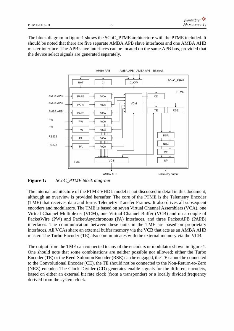
The block diagram in figure 1 shows the SCoC_PTME architecture with the PTME included. Itshould be noted that there are five separate AMBA APB slave interfaces and one AMBA AHBmaster interface. The APB slave interfaces can be located on the same APB bus, provided thatthe device select signals are generated separately.
Figure 1: SCoC_PTME block diagram
The internal architecture of the PTME VHDL model is not discussed in detail in this document,although an overview is provided hereafter. The core of the PTME is the Telemetry Encoder(TME) that receives data and forms Telemetry Transfer Frames. It also drives all subsequentencoders and modulators. The TME is based on seven Virtual Channel Assemblers (VCA), oneVirtual Channel Multiplexer (VCM), one Virtual Channel Buffer (VCB) and on a couple ofPacketWire (PW) and PacketAsynchronous (PA) interfaces, and three PacketAPB (PAPB)interfaces. The communication between these units in the TME are based on proprietaryinterfaces. All VCAs share an external buffer memory via the VCB that acts as an AMBA AHBmaster. The Turbo Encoder (TE) also communicates with the external memory via the VCB.
The output from the TME can connected to any of the encoders or modulator shown in figure 1.One should note that some combinations are neither possible nor allowed: either the TurboEncoder (TE) or the Reed-Solomon Encoder (RSE) can be engaged, the TE cannot be connectedto the Convolutional Encoder (CE), the TE should not be connected to the Non-Return-to-Zero(NRZ) encoder. The Clock Divider (CD) generates enable signals for the different encoders,based on either an external bit rate clock (from a transponder) or a locally divided frequencyderived from the system clock.
PW
CLCWCI
RSE
PSR
NRZ
SP
CD
VCM
VCB
PW
PTME
VCA
VCA
VCA
VCA
PW
PW
Telemetry output
Bit clock
VCA
PAPB
PAPBAMBA APB
AMBA APB
PAPBAMBA APB
AMBA APB
BAT
AMBA APB
PARS232
PARS232
VCA
VCA
TE
CE
TME
SCoC_PTME
AMBA AHB
AMBA APB

PTME-002-01 7
4 PARAMETER SETTINGS
The VHDL parameter settings used for the SCoC_PTME are listed in table 3 and table 4.
Parameter Type Value Result Description
Parameters related to all Virtual Channels of the Telemetry Encoder (TME)
gNumberOfVCs Natural 7 VC0 - VC6 Number of VCs
gIdleFrameVC Natural 7 VC7 Identification of VC to use for Idle Transfer Frames
gFlexVCId Natural 0 none no flexible VC Id allocation
Constants related to the memory size and partitioning
gMemoryDepth Positive 19 512 kByte Amount of memory to be shared by all VCs
gAreaDepth Positive 4 16 areas Number of areas into which memory is partitioned
gGroupDepth Positive 2 4 Maximum number of memory areas allowed for any VC
gGroupInterface Natural 0 internal automatic internal and fixed memory area assignment
Bandwidth Allocation Table configuration
gBatDepth Positive 5 32 Number of BAT entries
Configuration of PTME capabilities
gFrameLength Natural 0 223 based Frame lengths 223, 486, 892, 1115
gAltASM Natural 0 none Alternate Attached Synchronisation Marker support
gTime Natural 1 supported Time Strobe support
gSecHeader Natural 1 supported Secondary Header support
gOPCF Natural 1 supported OPCF/CLCW support
gOPCFLength Natural 0 16 bit Dynamic part of CLCW
gOPCFInterface Natural 1 external synchronous-parallel (implemented in SCoC_PTME)
gFECW Natural 1 supported FECW/CRC support
gBatInterface Natural 2 external synchronous-parallel (implemented in SCoC_PTME)
gPreLength Natural 4 5 octets Virtual Channel Multiplexer prefetch buffer size
gReedSolomon Natural 1 supported classical CCSDS / ESA PSS encoding
gRSStyle Natural 0 flip-flop flip-flops used for check symbol memory
gUnContiguous Natural 0 no no uncontiguous non-standard CADUs support
gTurbo Natural 1 supported Turbo encoder support
gTurboLatency Natural 0 no No Turbo latency optimisation
gTurboLengthRd Natural 2 unused Turbo read buffer size
gTurboLengthWr Natural 4 unused Turbo write buffer size
gPseudo Natural 1 supported Pseudo-Randomiser encoding support
gMark Natural 1 supported NRZ-Mark encoding support
gConvolute Natural 1 basic classical CCSDS / ESA PSS encoding
gSplit Natural 1 supported Split Phase Level encoding support
Table 3: SCoC_PTME parameter settings

PTME-002-01 8
Clock divider and clocking style configuration
gClockDepth Positive 8 1/1 - 1/256 Clock divider width
gCommonClock Natural 0 separate Separate bit and system clocks
gClockStyle Natural 1 output Bit clock used for output bit rate
gClkFrequency Natural 16E6 16 MHz PacketAsynchronous receiver rates based on 16 MHz
gSyncReset Natural 0 async Asynchronous reset
gOPCFBitClock Natural 0 n/a (CLCW interface implemented in SCoC_PTME)
Memory addressing style
gPhysicalAddress Natural 0 logical Logical pointers used internally
gPhysicalDepth Positive 32 n/a Physical address width
gMemoryInterface Natural 0 AHB AMBA AHB interface
gWaitStates Natural 0 n/a Wait State support
gWaitStateDepth Positive 1 n/a Maximum number of wait states
gEdacSupport Natural 0 n/a None
gEdacType Natural 0 n/a Hamming Code / Cyclic Code
gMemoryTest Natural 0 none Memory test support
Design optimization and simplification
gFPGA Natural 1 optimised FPGA optimization
gSlowVCAExtra Natural 0 fast No slow access support for VCA extra write
gSlowVCAWrite Natural 0 fast No slow access support for VCA nominal write
gAcknowledgeVCB Natural 0 none No acknowledge support in VCB
gFrameCheck Natural 0 none No frame status check in VCM
Parameter TypeVirtual Channel
Description0 1 2 3 4 5 6
Constants related to the individual Virtual Channels of the Telemetry Encoder (TME)
gPacket Natural 1 1 1 1 1 0 0 Telemetry Packet support
gIdle Natural 0 0 1 1 1 0 0 Idle Telemetry Packet generation support
gReady Natural 1 1 1 1 1 1 1 Ready-for-segment signalling support
gEmpty Natural 0 0 0 0 0 0 0 Buffer empty signalling support
gAbort Natural 0 0 0 0 0 0 0 Abort Telemetry Packet support
gLength Natural 3 3 3 3 3 3 3 Input buffer of 4 octets for Virtual Channel Assembler
gInterface Natural 3 3 3 0 0 1 1 0=PacketWire, 1=PacketAsynchronous, 2=PacketParallel, 3=AMBA APB (PAPB)
gPAPBDataSize Natural 1 1 1 1 1 1 1 PacketAPB data width: 8 bits
gGroupSize Natural 1 1 2 1 1 1 1 2^n memory areas allocated to Virtual Channel
Table 4: SCoC_PTME parameter settings (for individual Virtual Channels)
Parameter Type Value Result Description
Table 3: SCoC_PTME parameter settings

PTME-002-01 9
5 DESCRIPTION
5.1 Configuration Interface (CI)
The SCoC_PTME can be configured via the Configuration interface (CI) which is an AMBAAPB slave interface. This interface also allows to read the CLCW data that is written via theCLCW interfaces described in section 5.2. The separation between the configuration interfaceand the CLCW interfaces has been done to allow two telecommand decoders to directly writeCLCW data to the telemetry encoder without the need to share the APB bus, notwithstandingthe clock and reset signals.
The AMBA APB slave interface supports 16 bit wide data input and output. The input addressis interpreted as a byte address, as per AD4. Since each access is a word access, the two leastsignificant address bits are assumed always to be zero. Only address bits 8:2 are decoded,although not always completely. Misaligned addressing is not supported. For read accesses, dataoutput is produced combinatorially from the address. The unused data bits 31:16 are alwaysdriven to zero. The interface is designed to work in a multiplexed unidirectional bus scheme.Re-mapping between the opposing numbering conventions in the CCSDS and AMBAdocumentation is performed. When the CCSDS field is narrower than the AMBA data width,zeros are padded to the left as shown in the register definitions hereafter.
After a re-configurations the SCoC_PTME needs to be reset via the Reset Register, as stated inthe register definitions hereafter. The register values after a SCoC_PTME reset are also listed inthe register definitions hereafter.
Register name Address Read/Write Remark Reference
Spacecraft Configuration Register ---- 0000h r/w Spacecraft Identification table 6
Frame Configuration Register ---- 0004h r/w Transfer Frame configuration table 7
Encoding Configuration Register ---- 0008h r/w Channel coding configuration table 8
Data Rate Configuration Register ---- 000Ch r/w Clock divider configuration table 13
CLCW Configuration Register ---- 0010h r/w CLCW configuration table 10
CLCW 0 Data ---- 0014h r CLCW 0 data read out table 11
CLCW 1 Data ---- 0018h r CLCW 1 data read out
Reset Register ---- 001Ch r/w Reset register for PTME core table 12
Flexible VC Id - VC 0 ---- 0080h r/w Individual setting of Virtual Channel Identifier(unused)
table 14
...
Flexible VC Id - VC 6 ---- 0098h
VC Configuration Register - VC 0 ---- 0100h r/w Individual Virtual Channel configurations
table 9
...
VC Configuration Register - VC 6 ---- 0118h
Bandwidth Allocation Table - 0 ---- 0180h r/w Telemetry channel bandwidth allocation
table 15
...
Bandwidth Allocation Table - 31 ---- 01FCh
Table 5: Address mapping for Configuration Interface (CI) AMBA APB slave interface
PTME-002-01 10
Bit number Mode Default Name Remarks
15:10 r all zero unused all zero during read
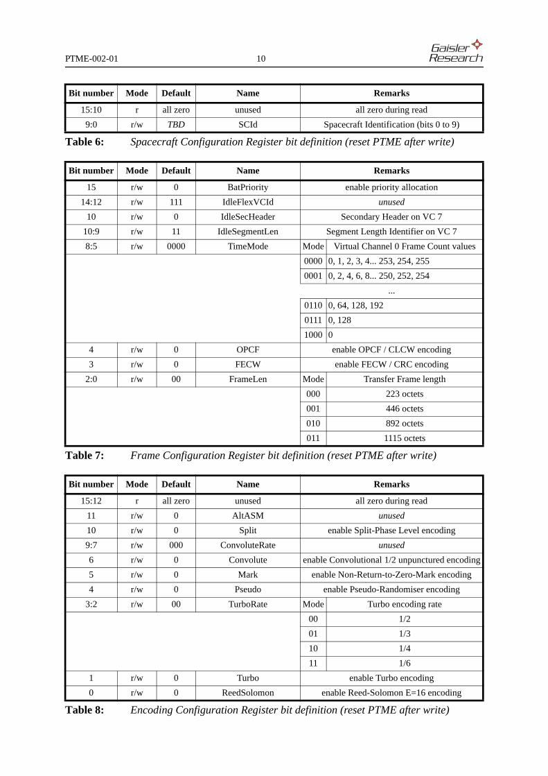
9:0 r/w TBD SCId Spacecraft Identification (bits 0 to 9)
Table 6: Spacecraft Configuration Register bit definition (reset PTME after write)
Bit number Mode Default Name Remarks
15 r/w 0 BatPriority enable priority allocation
14:12 r/w 111 IdleFlexVCId unused
10 r/w 0 IdleSecHeader Secondary Header on VC 7
10:9 r/w 11 IdleSegmentLen Segment Length Identifier on VC 7
8:5 r/w 0000 TimeMode Mode Virtual Channel 0 Frame Count values
0000 0, 1, 2, 3, 4... 253, 254, 255
0001 0, 2, 4, 6, 8... 250, 252, 254
...
0110 0, 64, 128, 192
0111 0, 128
1000 0
4 r/w 0 OPCF enable OPCF / CLCW encoding
3 r/w 0 FECW enable FECW / CRC encoding
2:0 r/w 00 FrameLen Mode Transfer Frame length
000 223 octets
001 446 octets
010 892 octets
011 1115 octets
Table 7: Frame Configuration Register bit definition (reset PTME after write)
Bit number Mode Default Name Remarks
15:12 r all zero unused all zero during read
11 r/w 0 AltASM unused
10 r/w 0 Split enable Split-Phase Level encoding
9:7 r/w 000 ConvoluteRate unused
6 r/w 0 Convolute enable Convolutional 1/2 unpunctured encoding
5 r/w 0 Mark enable Non-Return-to-Zero-Mark encoding
4 r/w 0 Pseudo enable Pseudo-Randomiser encoding
3:2 r/w 00 TurboRate Mode Turbo encoding rate
00 1/2
01 1/3
10 1/4
11 1/6
1 r/w 0 Turbo enable Turbo encoding
0 r/w 0 ReedSolomon enable Reed-Solomon E=16 encoding
Table 8: Encoding Configuration Register bit definition (reset PTME after write)
PTME-002-01 11
Bit number Mode Default Name Remarks
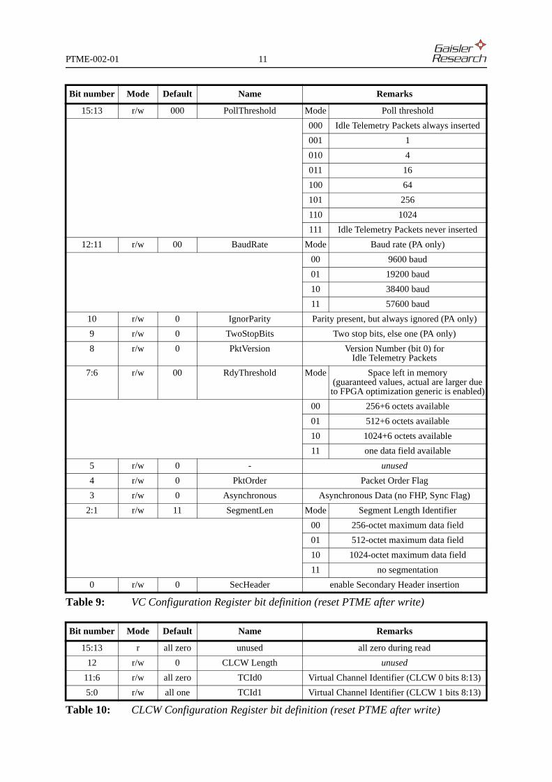
15:13 r/w 000 PollThreshold Mode Poll threshold
000 Idle Telemetry Packets always inserted
001 1
010 4
011 16
100 64
101 256
110 1024
111 Idle Telemetry Packets never inserted
12:11 r/w 00 BaudRate Mode Baud rate (PA only)
00 9600 baud
01 19200 baud
10 38400 baud
11 57600 baud
10 r/w 0 IgnorParity Parity present, but always ignored (PA only)
9 r/w 0 TwoStopBits Two stop bits, else one (PA only)
8 r/w 0 PktVersion Version Number (bit 0) for Idle Telemetry Packets
7:6 r/w 00 RdyThreshold Mode Space left in memory (guaranteed values, actual are larger due to FPGA optimization generic is enabled)
00 256+6 octets available
01 512+6 octets available
10 1024+6 octets available
11 one data field available
5 r/w 0 - unused
4 r/w 0 PktOrder Packet Order Flag
3 r/w 0 Asynchronous Asynchronous Data (no FHP, Sync Flag)
2:1 r/w 11 SegmentLen Mode Segment Length Identifier
00 256-octet maximum data field
01 512-octet maximum data field
10 1024-octet maximum data field
11 no segmentation
0 r/w 0 SecHeader enable Secondary Header insertion
Table 9: VC Configuration Register bit definition (reset PTME after write)
Bit number Mode Default Name Remarks
15:13 r all zero unused all zero during read
12 r/w 0 CLCW Length unused
11:6 r/w all zero TCId0 Virtual Channel Identifier (CLCW 0 bits 8:13)
5:0 r/w all one TCId1 Virtual Channel Identifier (CLCW 1 bits 8:13)
Table 10: CLCW Configuration Register bit definition (reset PTME after write)

PTME-002-01 12
Bit number Mode Default Name Remarks
15:0 w all zero CLCW data CLCW data bits 16:31
Table 11: CLCW Data Register bit definition (reset PTME after write)
Bit number Mode Default Name Remarks
15:1 r all zero unused all zero during read
0 r/w 0 Reset resets the PTME while asserted
Table 12: Reset Register bit definition
Bit number Mode Default Name Remarks
15:9 r all zero unused all zero during read
8 r/w 0 OutputClock Mode clock source for output bit rate
0 system clock
1 external bit rate clock
7:0 r/w all zero OutputBitRate Mode bit rate division
00h 1/1
01h 1/2
...
FFh 1/256
Table 13: Data Rate Configuration Register bit definition (reset PTME after write)
Bit number Mode Default Name Remarks
15:3 r all zero unused all zero during read
2:0 r/w entry # Virtual Channel Id unused
Table 14: Flexible VC Id bit definition (reset PTME after write)
Bit number Mode Default Name Remarks
15:3 r all zero unused all zero during read
2:0 r/w entry # mod 7
Virtual Channel Id valid values are 0, 1, 2, 3, 4, 5 and 6,other values disable slot allocation
Table 15: Bandwidth Allocation Table bit definition (reset PTME after write)
Virtual Channel Share Percentage Remark
0 5 of 32 15.625%
1 5 of 32 15.625%
2 5 of 32 15.625%
3 5 of 32 15.625%
4 4 of 32 12.5%
5 4 of 32 12.5%
6 4 of 32 12.5%
Table 16: Default Bandwidth Allocation after SCoC_PTME reset

PTME-002-01 13
5.2 Command Link Control Word interfaces (CLCW0 and CLCW1)
The interface for transmitting the Command Link Control Word (CLCW) to the TelemetryEncoder (TME) is done via two specific and separate AMBA APB slave interfaces. There is oneCLCW Data Registers that can be written to independently of the Telemetry Transfer Framegeneration done by the TME. The CLCW that is being output by the TME is buffered in theSCoC_PTME not to pose any requirements on the AMBA APB interfaces. The data from thetwo CLCW Data Registers are transmitted in every other Telemetry Transfer Frame, CLCW 0data being transmitted for even Master Channel counts, and CLCW 1 data being transmitted forodd Master Channel counts. All sixteen bits received via the AMBA APB slave interfaces areused by the Telemetry Encoder (TME), including the RF Available Flag (CLCW bit 16) and theBit Lock Flag (CLCW bit 17).
The Virtual Channel Identifier (CLCW bits 8 to 13) is taken from the CLCW ConfigurationRegister described in table 10, where TCId0 is used in conjunction with the CLCW 0 DataRegister, and TCId1 is used in conjunction with the CLCW 1 Data Register. The remaining bitsare statically assigned as documented in AD1.
The AMBA APB slave interfaces support 16 bit wide data input and output. The input addressis interpreted as a byte address, as per AD4. Since each access is a word access, the two leastsignificant address bits are assumed always to be zero. No address bit is decoded. Misalignedaddressing is not supported. For read accesses, data is always output. The unused data bits 31:16are always driven to zero. The interfaces are designed to work in a multiplexed unidirectionalbus scheme. Re-mapping between the opposing numbering conventions in the CCSDS andAMBA documentation is performed. When the CCSDS field is narrower than the AMBA datawidth, zeros are padded to the left as shown in the register definitions hereafter.
5.3 PacketWire (PW) interface
The PacketWire interface (PW) to a Virtual Channel is described in detail in AD1. Theinterfaces in the SCoC_PTME do not support packet length check and packet abort. IdleTelemetry Packet insertion is supported for all Virtual Channels with PW interfaces in theSCoC_PTME, see table 4. The PW interface supports packets or data sizes in multiple of 8 bits.
Register name Address Read/Write Remark Reference
CLCW 0 Data Register ---- ----h r/w CLCW 0 data table 18
CLCW 1 Data Register ---- ----h r/w CLCW 1 data
Table 17: Address mapping for the two CLCW 0 and CLCW0 AMBA APB slave interfaces
Bit number Mode Default Name Remarks
15:0 r/w all zero CLCW data CLCW data bits 16:31
Table 18: CLCW Data Register bit definition

PTME-002-01 14
5.4 PacketAPB interface (PAPB)
The PacketAPB interface (PABP) to a Virtual Channel is described in detail in AD1. It hashowever been partially repeated here for sake of completeness. There are three PacketAPBinterfaces in the SCoC_PTME. These AMBA APB slave interfaces can be located on the sameAPB bus, provided that the corresponding select signals are generated separately.
The interface supports 8 bit wide data input and output. The input address is interpreted as a byteaddress, as per AD4. Since each access is a word access, the two least significant address bitsare assumed always to be zero. Only address bit 10 is decoded during write accesses, to allowa maximum burst of 1024 words to the PAPB Data Input Register. Misaligned addressing is notsupported. The address is not decoded during read accesses, neither are the select, enable andwrite strobes. Only the PAPB Configuration Register can be read. The unused data bits 31:7 arealways driven to zero. The interface is designed to work in a multiplexed unidirectional busscheme. Re-mapping between the opposing numbering conventions in the CCSDS and AMBAdocumentation is performed. When the CCSDS field is narrower than the AMBA data width,zeros are padded to the left as shown in the register definitions hereafter.
Precaution should be taken when deciding the clocking frequency for the AMBA APB andAHB clocks. Enough time should be given to allow the Valid bit to be synchronised andpropagated to the telemetry encoder between two writes accesses to the PAPB ConfigurationRegister. Packet length check and support for aborting packets are not included. Idle TelemetryPacket insertion is only supported for some Virtual Channels in the SCoC_PTME, see table 4.The interface provides a signal indicating the amount of data space that is left for the associatedVirtual Channel and a signal indicating whether the interface is momentarily busy.
Register name Address Read/Write Remark Reference
Configuration Register ---- -0--h r/w configuration and status table 20
Data Input Register ---- -4--h w data transfer table 21
Table 19: Address mapping for PacketAPB AMBA APB slave interface
Bit number Mode Default Name Remarks
31:7 r all zeros unused all zero during read
6 r 0 Ready Interface ready to receive a segment
5 r 0 Busy Interface busy
4 r 0 - unused
3 r/w 0 Valid Packet delimiter when asserted
2 r/w 0 Abort unused
1:0 r/w 00 Size unused
Table 20: PacketAPB Configuration Register bit definition
Bit number Mode Default Name Remarks
31:8 n/a n/a unused unused, since interface limited to one octet
7:0 w n/a data only transmitted octet (bits 0:7)
Table 21: PacketAPB Data Input Register bit definition

PTME-002-01 15
5.5 PacketAsynchronous (PA) interface
The PacketAsynchronous interface (PA) to a Virtual Channel is described in detail in AD1. ThePA interfaces in the SCoC_PTME do not support packet length check, packet abort, and IdleTelemetry Packet insertion. The baud rate and transmission format is configured by means ofthe Configuration Interface (CI) described in section 5.1 and table 9. In addition to the bit serialdata input, which is sampled with the AMBA AHB clock, the interface provides a signalindicating the amount of data space that is left for the associated Virtual Channel. The PAinterfaces can only be used for Asynchronous Data operation as described in RD1, since no FirstHeader Pointer support is implemented for the corresponding Virtual Channels. Note that thecorresponding Sync Flag needs to be set accordingly in table 9. The PA interface supports 8 bitdata, with 1 or 2 stop bits, and a parity bit can be masked if required although parity is unused.
5.6 Channel Access Data Unit output interface
The telemetry and channel encoded output from the SCoC_PTME is provided via a bit serialoutput together with an associated output bit clock. To support analysis of the data stream adelimiter is asserted during the transmission of the Attached Synchronisation Marker, and asecond delimiter is asserted during the transmission of the Telemetry Transfer Frame.
A time strobe is generated according to RD1, being asserted simultaneously with the first bit ofthe Attached Synchronisation Marker. The timing of the time strobe is not valid if TurboEncoding is applied because frame buffering takes place. The accuracy of the strobe is affectedby the usage of other encoders and modulator, usually by one bit clock period per simpleencoder. The time strobe is asserted for 128 bit clock periods.
The resulting data output rates depend on the clock divider settings as listed in table 13 and thechannel coding settings as listed in table 8. The output symbol rate, fo, can be obtained bydividing the AMBA HCLK input or the dedicated bit rate input BitClk (1/n, n={1 to 256}),actually generating clock enable pulses. Since bit rate generation is based on the output symbolrate, fo, of the last encoder or modulator used in the encoding chain, the telemetry bit rate, ftme,can vary for the same fo frequency depending on the used encoding scheme as shown intable 22.
TME
RSE TE
CE CE 1/2 1/3 1/4 1/6
SP SP SP SP SP SP SP SP
TME, ftme fo fo/2 fo/2 fo/4 fo fo/2 fo/2 fo/4 fo/2 fo/4 fo/3 fo/6 fo/4 fo/8 fo/6 fo/12
RSE, frse - - - - fo fo/2 fo/4 - - - - - - - -
TE, fte - - - - - - - - fo fo/2 fo fo/2 fo fo/2 fo fo/2
PSR, fte fo fo/2 fo/2 fo/4 fo fo/2 fo/2 fo/4 fo fo/2 fo fo/2 fo fo/2 fo fo/2
NRZ, fnrz fo fo/2 fo/2 fo/4 fo fo/2 fo/2 fo/4 fo fo/2 fo fo/2 fo fo/2 fo fo/2
CE, fce - - fo fo/2 - - fo fo/2 - - - - - - - -
SP, fsp - fo - fo - fo - fo - fo - fo - fo - fo
Table 22: Bit rates for different encoders based on the obtained output frequency

PTME-002-01 16
5.7 AMBA AHB master interface
The AMBA AHB master interface of the PTME is described in detail in AD1. It has howeverbeen to some extent repeated here for sake of completeness.
The AMBA AHB master interface has been reduced in function to support only what is requiredfor the PTME. The following AMBA AHB features are constrained:• does not support HRESP = ERROR, SPLIT or RETRY • assumed that accesses will always be completed with HRESP = OKAY• only generates HSIZE = BYTE• only generates HTRANS = NONSEQ or IDLE• only generates HBURST = SINGLE• only generates HPROT = 0000b• never asserts HLOCK• can act as a default master, responding to default HGRANT• only big-endianness supported.
Since only byte accesses are performed, the byte data to be written is copied to all four bytepositions on HWDATA during write accesses. The addressed byte is extracted from HRDATAfor read accesses.
The different Virtual Channels buffer the incoming data in the external buffer memory accessedvia the AMBA AHB master interface. Each Virtual Channel is assigned a portion of the memoryallocated to the SCoC_PTME. The overall memory allocation is 512 kBytes, divided into 16areas with 32678 bytes each. Each Virtual Channel can be assigned 1, 2, or 4 areas, as shown intable 23. The Turbo Encoder (TE) requires 4096 bytes of the external memory as shown intable 23. The allocation of areas is automatically done at compilation time and has beenoptimised to minimize the complexity of the design and to maximise the utilisation of theavailable memory.
The base address for all SCoC_PTME AMBA AHB accesses is all zero as shown in table 23.This can be modified external to the SCoC_PTME VHDL model if required. The relevantaddress signals could be replaced with other fixed value addresses signals when connecting tothe AMBA AHB arbiter/decoder.
Unit Address range Areas Remark
Virtual Channel 0 0007 0000h - 0007 EFFFh 2 reduced buffer size
Virtual Channel 1 0006 0000h - 0006 FFFFh 2
Virtual Channel 2 0000 0000h- 0001 FFFFh 4 increased buffer size
Virtual Channel 3 0005 0000h- 0005 FFFFh 2
Virtual Channel 4 0004 0000h- 0004 FFFFh 2
Virtual Channel 5 0003 0000h- 0003 FFFFh 2
Virtual Channel 6 0002 0000h- 0002 FFFFh 2
Turbo Encoder 0007 EFFFh- 0007 FFFFh n/a Turbo Encoder memory
Table 23: Memory mapping of the TME and TE on the AMBA AHB master interface

PTME-002-01 17
5.8 External buffer memory
The memory area allocation to individual Virtual Channel has been described in section 5.7 andlisted in table 23. The number of Telemetry Transfer Frames actually stored in the externalbuffer memory depends on the allocated memory area and the selected frame length as listed intable 7. The resulting information for the SCoC_PTME is listed in table 24.
The access bandwidth to the external buffer memory is dynamically allocated in the PTMEVHDL model, giving an equal amount of guaranteed bandwidth to the different units. Theinternal arbiter in the PTME VHDL model scans requests from all units in parallel to decidewhich unit will be granted an access the next time. The arbiter follows a simple round robinscheme where each Virtual Channel Assembler (VCA) is assigned one write slot, the VirtualChannel Multiplexer (VCM) is assigned one read slot, the Turbo Encoder is assigned one readand one write slot, and finally all VCAs are assigned one common slot for extra write accesses.This extra write access slot is also arbitrated in a round robin fashion for the different VCAs,but only takes one slot in the overall arbitration. Extra write accesses are used for writing FirstHeader Pointer data and Idle Telemetry Packet data without occupying any of the bandwidththat is guaranteed for normal data transfers from the VCAs. The Virtual Channel dedicated toIdle Transfer Frame generation does not require any memory area or access bandwidth.
Each access type, read and write, takes one HCLK clock period to complete, provided there areno wait states on the AMBA AHB bus. The latency and the jitter is compensated by means ofinput buffers on the VCAs and the VCM. The arbiter and the AHB master can under optimalconditions sustain full utilisation of the bus without idle clock periods.
In order to assess the bandwidth requirement on the AHB bus one needs to consider each unitseparately. The PacketAPB (PAPB) interface provides a very direct flow control interface whichcan be used to reduce the requirement on latency for the interface. The PacketWire (PW)interface provides a flow control interface, but since serial in nature makes it more difficult forthe source to precisely react on the response, which would lead to a stronger requirement on lowlatency. However, if one knows the transfer rate of the source, the bandwidth requirement canbe reduced. The PacketAsynchronous (PA) interface lacks flow control, which leads to thestrongest latency requirement. However, by knowing the baud rate of the PA interface, thebandwidth requirement can be reduced.
Unit Areas
Frame size
Remark223 446 892 1115
Number of frames in memory
Virtual Channel 0 2 240 120 60 30 reduced due to turbo encoder
Virtual Channel 1 2 256 128 64 32
Virtual Channel 2 4 512 256 128 64 increased size
Virtual Channel 3 2 256 128 64 32
Virtual Channel 4 2 256 128 64 32
Virtual Channel 5 2 256 128 64 32
Virtual Channel 6 2 256 128 64 32
Table 24: Number of stored Telemetry Transfer Frames in external buffer memory
PTME-002-01 18
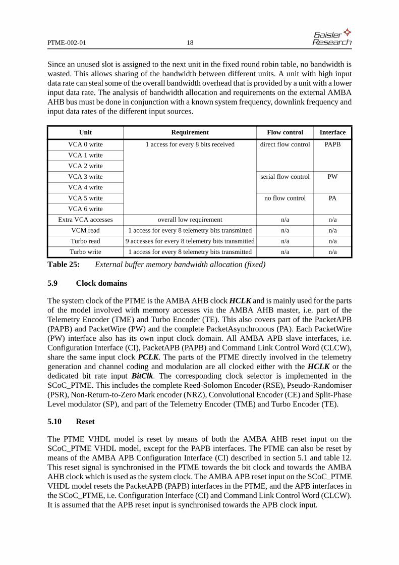
Since an unused slot is assigned to the next unit in the fixed round robin table, no bandwidth iswasted. This allows sharing of the bandwidth between different units. A unit with high inputdata rate can steal some of the overall bandwidth overhead that is provided by a unit with a lowerinput data rate. The analysis of bandwidth allocation and requirements on the external AMBAAHB bus must be done in conjunction with a known system frequency, downlink frequency andinput data rates of the different input sources.
5.9 Clock domains
The system clock of the PTME is the AMBA AHB clock HCLK and is mainly used for the partsof the model involved with memory accesses via the AMBA AHB master, i.e. part of theTelemetry Encoder (TME) and Turbo Encoder (TE). This also covers part of the PacketAPB(PAPB) and PacketWire (PW) and the complete PacketAsynchronous (PA). Each PacketWire(PW) interface also has its own input clock domain. All AMBA APB slave interfaces, i.e.Configuration Interface (CI), PacketAPB (PAPB) and Command Link Control Word (CLCW),share the same input clock PCLK. The parts of the PTME directly involved in the telemetrygeneration and channel coding and modulation are all clocked either with the HCLK or thededicated bit rate input BitClk. The corresponding clock selector is implemented in theSCoC_PTME. This includes the complete Reed-Solomon Encoder (RSE), Pseudo-Randomiser(PSR), Non-Return-to-Zero Mark encoder (NRZ), Convolutional Encoder (CE) and Split-PhaseLevel modulator (SP), and part of the Telemetry Encoder (TME) and Turbo Encoder (TE).
5.10 Reset
The PTME VHDL model is reset by means of both the AMBA AHB reset input on theSCoC_PTME VHDL model, except for the PAPB interfaces. The PTME can also be reset bymeans of the AMBA APB Configuration Interface (CI) described in section 5.1 and table 12.This reset signal is synchronised in the PTME towards the bit clock and towards the AMBAAHB clock which is used as the system clock. The AMBA APB reset input on the SCoC_PTMEVHDL model resets the PacketAPB (PAPB) interfaces in the PTME, and the APB interfaces inthe SCoC_PTME, i.e. Configuration Interface (CI) and Command Link Control Word (CLCW).It is assumed that the APB reset input is synchronised towards the APB clock input.
Unit Requirement Flow control Interface
VCA 0 write 1 access for every 8 bits received direct flow control PAPB
VCA 1 write
VCA 2 write
VCA 3 write serial flow control PW
VCA 4 write
VCA 5 write no flow control PA
VCA 6 write
Extra VCA accesses overall low requirement n/a n/a
VCM read 1 access for every 8 telemetry bits transmitted n/a n/a
Turbo read 9 accesses for every 8 telemetry bits transmitted n/a n/a
Turbo write 1 access for every 8 telemetry bits transmitted n/a n/a
Table 25: External buffer memory bandwidth allocation (fixed)
PTME-002-01 19
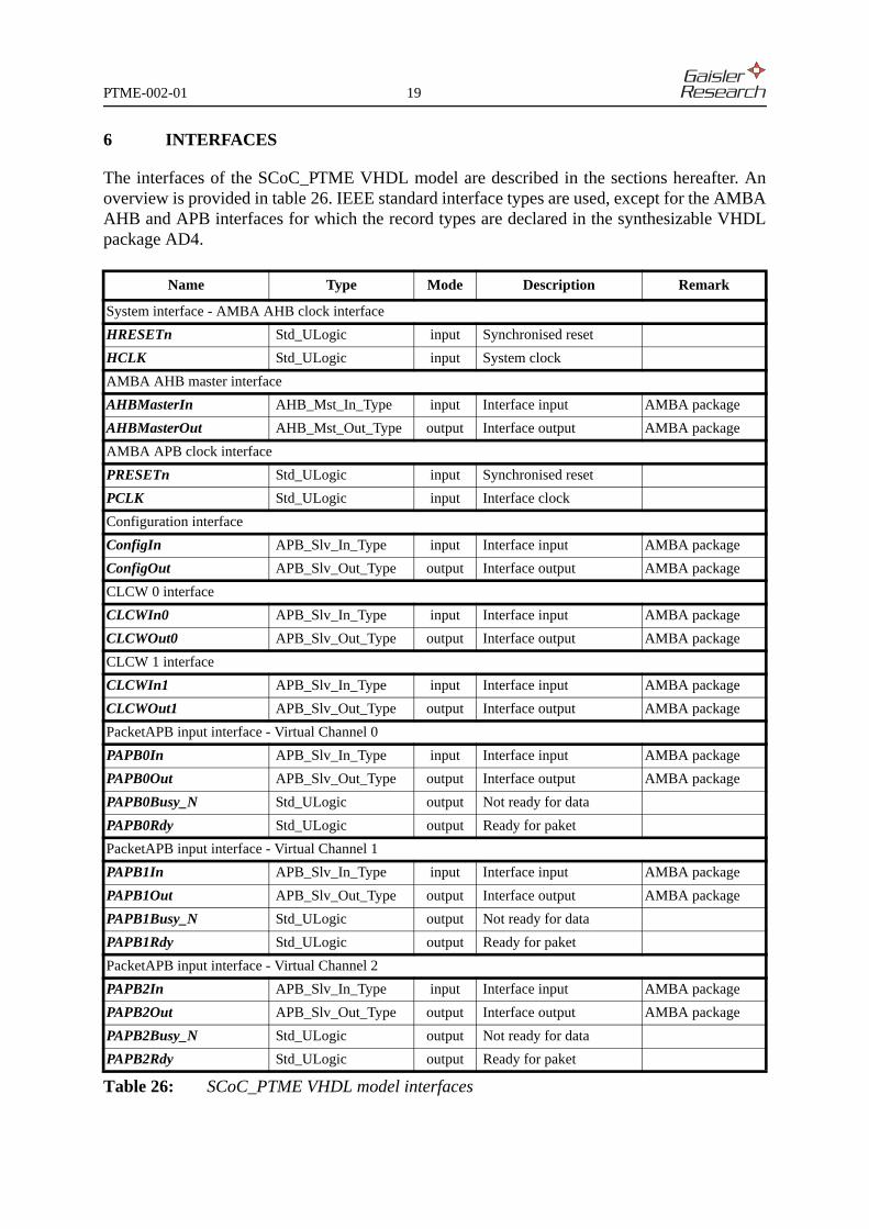
6 INTERFACES
The interfaces of the SCoC_PTME VHDL model are described in the sections hereafter. Anoverview is provided in table 26. IEEE standard interface types are used, except for the AMBAAHB and APB interfaces for which the record types are declared in the synthesizable VHDLpackage AD4.
Name Type Mode Description Remark
System interface - AMBA AHB clock interface
HRESETn Std_ULogic input Synchronised reset
HCLK Std_ULogic input System clock
AMBA AHB master interface
AHBMasterIn AHB_Mst_In_Type input Interface input AMBA package
AHBMasterOut AHB_Mst_Out_Type output Interface output AMBA package
AMBA APB clock interface
PRESETn Std_ULogic input Synchronised reset
PCLK Std_ULogic input Interface clock
Configuration interface
ConfigIn APB_Slv_In_Type input Interface input AMBA package
ConfigOut APB_Slv_Out_Type output Interface output AMBA package
CLCW 0 interface
CLCWIn0 APB_Slv_In_Type input Interface input AMBA package
CLCWOut0 APB_Slv_Out_Type output Interface output AMBA package
CLCW 1 interface
CLCWIn1 APB_Slv_In_Type input Interface input AMBA package
CLCWOut1 APB_Slv_Out_Type output Interface output AMBA package
PacketAPB input interface - Virtual Channel 0
PAPB0In APB_Slv_In_Type input Interface input AMBA package
PAPB0Out APB_Slv_Out_Type output Interface output AMBA package
PAPB0Busy_N Std_ULogic output Not ready for data
PAPB0Rdy Std_ULogic output Ready for paket
PacketAPB input interface - Virtual Channel 1
PAPB1In APB_Slv_In_Type input Interface input AMBA package
PAPB1Out APB_Slv_Out_Type output Interface output AMBA package
PAPB1Busy_N Std_ULogic output Not ready for data
PAPB1Rdy Std_ULogic output Ready for paket
PacketAPB input interface - Virtual Channel 2
PAPB2In APB_Slv_In_Type input Interface input AMBA package
PAPB2Out APB_Slv_Out_Type output Interface output AMBA package
PAPB2Busy_N Std_ULogic output Not ready for data
PAPB2Rdy Std_ULogic output Ready for paket
Table 26: SCoC_PTME VHDL model interfaces

PTME-002-01 20
PacketWire input interface - Virtual Channel 3
PW3Valid Std_ULogic input Packet delimiter
PW3Clk Std_ULogic input Bit clock
PW3Data Std_ULogic input Data
PW3Rdy Std_ULogic output Ready for paket
PacketWire input interface - Virtual Channel 4
PW4Valid Std_ULogic input Packet delimiter
PW4Clk Std_ULogic input Bit clock
PW4Data Std_ULogic input Data
PW4Rdy Std_ULogic output Ready for paket
PacketAsynchronous input interface - Virtual Channel 5
PW5Data Std_ULogic input Data
PA5Rdy Std_ULogic output Ready for paket
PacketAsynchronous input interface - Virtual Channel 6
PW6Data Std_ULogic input Data
PA6Rdy Std_ULogic output Ready for paket
Channel Access Data Unit output interface
BitClk Std_ULogic input Bit clock
TimeStrobe Std_ULogic output Time strobe
CADUSyncMark Std_ULogic output ASM delimiter
CADUFrameMark Std_ULogic output Transfer frame delimiter
CADUClk Std_ULogic output CADU clock
CADUOut Std_ULogic output CADU data
Name Type Mode Description Remark
Table 26: SCoC_PTME VHDL model interfaces

PTME-002-01 21
6.1 System interface (AMBA AHB clock interface)
For detailed information see AD2 and AD4.
6.1.1 HRESETn: Synchronised reset: Std_ULogic (I)
This active low input signal asynchronously resets the PTME VHDL model, except the PAPBinterfaces. The signal is assumed to be synchronous with the system clock HCLK rising edge.The input is used on registers that are all clocked on the rising HCLK edge.
6.1.2 HCLK: System clock: Std_ULogic (I)
This input signal is the system clock signal for the PTME VHDL model. Registers are clockedon the rising Clk edge.
6.2 AMBA AHB master interface
For detailed information on the record types used for the AMBA AHB interface see AD2 andAD4.
6.2.1 AHBMasterIn: Interface input: AHB_Mst_In_Type (I)
This signal record is the general AHB master interface input.
6.2.1.1 HGRANT: Bus grant: Std_ULogic (I)
This signal indicates that the AHB master is selected and a data transfer is required. The inputis sampled on the rising HCLK edge.
6.2.1.2 HREADY: Transfer done: Std_ULogic (I)
This signal indicates to the AHB master that an access is completed. The input is sampled onthe rising HCLK edge.
6.2.1.3 HRESP: Response type: Std_Logic_Vector(1 downto 0) (I)
This signal indicates to the AHB master with what a result an access has been completed. Theinput is sampled on the rising HCLK edge.
6.2.1.4 HRDATA: Read data bus: Std_Logic_Vector(HDMAX-1 downto 0) (I)
This signal provides the AHB master read data at the end of the access. The input is sampled onthe rising HCLK edge. HDMAX is defined in the AMBA VHDL package, AD4. HDMAX isassumed to be the default 32.

PTME-002-01 22
6.2.2 AHBMasterOut: Interface output: AHB_Mst_Out_Type (O)
This signal record is the general AHB master interface output.
6.2.2.1 HBUSREQ: Bus request: Std_ULogic (O)
This signal indicates that the AHB master is requesting the bus. The output is clocked out onthe rising HCLK edge.
6.2.2.2 HLOCK: Lock request: Std_ULogic (O)
This signal indicates whether the AHB master is requesting a locked access. The output ispermanently driven to logical zero.
6.2.2.3 HTRANS: Transfer type: Std_Logic_Vector(1 downto 0) (O)
This signal indicates the type of the transfer that the AHB master is issuing. The output isclocked out on the rising HCLK edge.
6.2.2.4 HADDR: Address: Std_Logic_Vector(HAMAX-1 downto 0) (O)
This signal carries the address of the transfer that the AHB master is issuing. The output isclocked out on the rising HCLK edge. HAMAX is defined in the AMBA VHDL package, AD4.HAMAX is assumed to be the default 32.
6.2.2.5 HWRITE: Read / Write: Std_ULogic (O)
This signal indicates whether it is a read or a write access that the AHB master is issuing. Theoutput is clocked out on the rising HCLK edge.
6.2.2.6 HSIZE: Transfer size: Std_Logic_Vector(2 downto 0) (O)
This signal indicates the size of the access that the AHB master issuing. The output ispermanently driven to logical zeros, indicating a byte access.
6.2.2.7 HBURST: Burst type: Std_Logic_Vector(2 downto 0) (O)
This signal indicates the burst type of access that the AHB master issuing. The output ispermanently driven to logical zeros, indicating a single access.
6.2.2.8 HPROT: Protection control: Std_Logic_Vector(32 downto 0) (O)
This signal indicates the protection type of access that the AHB master issuing. The output ispermanently driven to logical zeros.
6.2.2.9 HWDATA: Write data bus: Std_Logic_Vector(HDMAX-1 downto 0) (O)
This signal carries the data of the write transfer that the AHB master is issuing. The output isclocked out on the rising HCLK edge. HDMAX is defined in the AMBA VHDL package, AD4.HDMAX is assumed to be the default 32.

PTME-002-01 23
6.3 AMBA APB clock interface
For detailed information on the two first signals see AD2 and AD4.
6.3.1 PRESETn: Synchronised reset: Std_ULogic (I)
This active low input signal asynchronously resets the AMBA APB interfaces in theSCoC_PTME and PTME. The signal is assumed to be synchronous with the AMBA APB clockPCLK rising edge. The input is used on registers that are all clocked on the rising PCLK edge.
6.3.2 PCLK: Interface clock: Std_ULogic (I)
This input signal is the AMBA APB clock which is the clock for the AMBA APB interfaces inthe PTME VHDL core. All registers are clocked on the rising PCLK edge.
6.4 AMBA APB slave interface definition
For detailed information on the records used for the APB interface see AD2 and AD4. There arefive AMBA APB slave interfaces in the SCoC PTME VHDL model, all having the same generictype definitions as detailed below. The different interfaces will be listed in the next sections.
6.4.1 APB_Slv_In_Type: Interface input: APB_Slv_In_Type (I)
This signal record is the general APB slave interface input.
6.4.1.1 PSEL: Slave select: Std_ULogic (I)
This signal indicates that the APB slave is selected and a data transfer is required. The input issampled on the rising PCLK edge for write accesses.
6.4.1.2 PENABLE: Enable strobe: Std_ULogic (I)
This strobe signal is used to time all accesses on the peripheral bus. The enable signal is used toindicate the second cycle of an APB transfer. The rising edge of PENABLE occurs in the middleof the APB transfer. The input is sampled on the rising PCLK edge for write accesses.
6.4.1.3 PADDR: Address bus: Std_Logic_Vector(PAMAX-1 downto 0) (I)
This is the APB address bus can be up to 32 bits wide. The input is sampled on the rising PCLKPAMAX is assumed to be the default 32.
6.4.1.4 PWRITE: Write strobe: Std_ULogic (I)
This signal indicates the APB transfer direction When asserted this signal indicates an APBwrite access and when de-asserted a read access. The input is sampled on the rising PCLK edge.
6.4.1.5 PWDATA: Write data bus: Std_Logic_Vector(PDMAX-1 downto 0) (I)
The APB write data bus is driven by the peripheral bus master during write cycles (whenPWRITE is asserted). The data is sampled on the rising PCLK edge for write accesses. PDMAXis defined in the AMBA VHDL package, AD4.

PTME-002-01 24
6.4.2 APB_Slv_Out_Type: Interface output: APB_Slv_Out_Type (O)
This signal record is the general APB slave interface output.
6.4.2.1 PRDATA: Read data bus: Std_Logic_Vector(PDMAX-1 downto 0) (O)
The APB read data bus is driven by the selected slave during read cycles (when PWRITE is de-asserted). PDMAX is defined in the AMBA VHDL package, AD4. PDMAX is assumed to be thedefault 32.
6.5 Configuration interface
6.5.1 ConfigIn: Interface input: APB_Slv_In_Type (I)
This signal record is the APB slave interface input of the configuration interface. For details seesection 6.4.1.
6.5.2 ConfigOut: Interface output: APB_Slv_Out_Type (O)
This signal record is the APB slave interface output of the configuration interface. For detailssee section 6.4.2.
6.6 CLCW 0 interface
6.6.1 CLCWIn0: Interface input: APB_Slv_In_Type (I)
This signal record is the APB slave interface input of the CLCW 0 interface. For details seesection 6.4.1.
6.6.2 CLCWOut0: Interface output: APB_Slv_Out_Type (O)
This signal record is the APB slave interface output of the CLCW 0 interface. For details seesection 6.4.2.
6.7 CLCW 1 interface
6.7.1 CLCWIn1: Interface input: APB_Slv_In_Type (I)
This signal record is the APB slave interface input of the CLCW 1 interface. For details seesection 6.4.1.
6.7.2 CLCWOut:1 Interface output: APB_Slv_Out_Type (O)
This signal record is the APB slave interface output of the CLCW 1 interface. For details seesection 6.4.2.
PTME-002-01 25
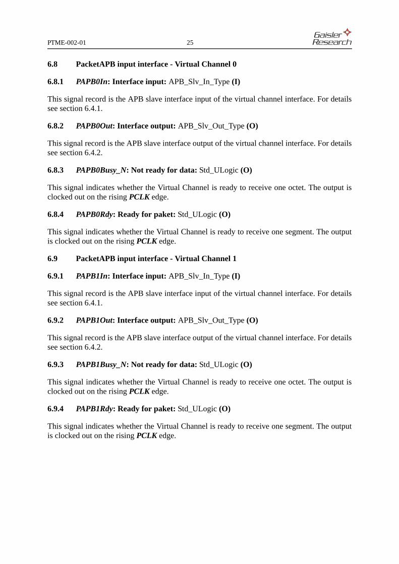
6.8 PacketAPB input interface - Virtual Channel 0
6.8.1 PAPB0In: Interface input: APB_Slv_In_Type (I)
This signal record is the APB slave interface input of the virtual channel interface. For detailssee section 6.4.1.
6.8.2 PAPB0Out: Interface output: APB_Slv_Out_Type (O)
This signal record is the APB slave interface output of the virtual channel interface. For detailssee section 6.4.2.
6.8.3 PAPB0Busy_N: Not ready for data: Std_ULogic (O)
This signal indicates whether the Virtual Channel is ready to receive one octet. The output isclocked out on the rising PCLK edge.
6.8.4 PAPB0Rdy: Ready for paket: Std_ULogic (O)
This signal indicates whether the Virtual Channel is ready to receive one segment. The outputis clocked out on the rising PCLK edge.
6.9 PacketAPB input interface - Virtual Channel 1
6.9.1 PAPB1In: Interface input: APB_Slv_In_Type (I)
This signal record is the APB slave interface input of the virtual channel interface. For detailssee section 6.4.1.
6.9.2 PAPB1Out: Interface output: APB_Slv_Out_Type (O)
This signal record is the APB slave interface output of the virtual channel interface. For detailssee section 6.4.2.
6.9.3 PAPB1Busy_N: Not ready for data: Std_ULogic (O)
This signal indicates whether the Virtual Channel is ready to receive one octet. The output isclocked out on the rising PCLK edge.
6.9.4 PAPB1Rdy: Ready for paket: Std_ULogic (O)
This signal indicates whether the Virtual Channel is ready to receive one segment. The outputis clocked out on the rising PCLK edge.
PTME-002-01 26
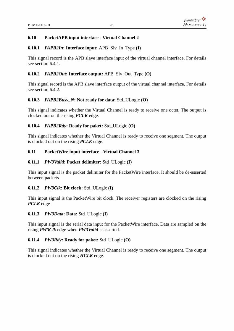
6.10 PacketAPB input interface - Virtual Channel 2
6.10.1 PAPB2In: Interface input: APB_Slv_In_Type (I)
This signal record is the APB slave interface input of the virtual channel interface. For detailssee section 6.4.1.
6.10.2 PAPB2Out: Interface output: APB_Slv_Out_Type (O)
This signal record is the APB slave interface output of the virtual channel interface. For detailssee section 6.4.2.
6.10.3 PAPB2Busy_N: Not ready for data: Std_ULogic (O)
This signal indicates whether the Virtual Channel is ready to receive one octet. The output isclocked out on the rising PCLK edge.
6.10.4 PAPB2Rdy: Ready for paket: Std_ULogic (O)
This signal indicates whether the Virtual Channel is ready to receive one segment. The outputis clocked out on the rising PCLK edge.
6.11 PacketWire input interface - Virtual Channel 3
6.11.1 PW3Valid: Packet delimiter: Std_ULogic (I)
This input signal is the packet delimiter for the PacketWire interface. It should be de-assertedbetween packets.
6.11.2 PW3Clk: Bit clock: Std_ULogic (I)
This input signal is the PacketWire bit clock. The receiver registers are clocked on the risingPCLK edge.
6.11.3 PW3Data: Data: Std_ULogic (I)
This input signal is the serial data input for the PacketWire interface. Data are sampled on therising PW3Clk edge when PW3Valid is asserted.
6.11.4 PW3Rdy: Ready for paket: Std_ULogic (O)
This signal indicates whether the Virtual Channel is ready to receive one segment. The outputis clocked out on the rising HCLK edge.

PTME-002-01 27
6.12 PacketWire input interface - Virtual Channel 4
6.12.1 PW4Valid: Packet delimiter: Std_ULogic (I)
This input signal is the packet delimiter for the PacketWire interface. It should be de-assertedbetween packets.
6.12.2 PW4Clk: Bit clock: Std_ULogic (I)
This input signal is the PacketWire bit clock. The receiver registers are clocked on the risingPCLK edge.
6.12.3 PW4Data: Data: Std_ULogic (I)
This input signal is the serial data input for the PacketWire interface. Data are sampled on therising PW3Clk edge when PW3Valid is asserted.
6.12.4 PW4Rdy: Ready for paket: Std_ULogic (O)
This signal indicates whether the Virtual Channel is ready to receive one segment. The outputis clocked out on the rising HCLK edge.
6.13 PacketAsynchronous input interface - Virtual Channel 5
6.13.1 PW5Data: Data: Std_ULogic (I)
This input signal is the bit serial asynchronous data input for the PacketAsynchronous interface.It is sampled on the rising HCLK edge.
6.13.2 PA5Rdy: Ready for paket: Std_ULogic (O)
This signal indicates whether the Virtual Channel is ready to receive one segment. The outputis clocked out on the rising HCLK edge.
6.14 PacketAsynchronous input interface - Virtual Channel 6
6.14.1 PW6Data: Data: Std_ULogic (I)
This input signal is the bit serial asynchronous data input for the PacketAsynchronous interface.It is sampled on the rising HCLK edge.
6.14.2 PA6Rdy: Ready for paket: Std_ULogic (O)
This signal indicates whether the Virtual Channel is ready to receive one segment. The outputis clocked out on the rising HCLK edge.

PTME-002-01 28
6.15 Channel Access Data Unit output interface
6.15.1 BitClk: Bit clock: Std_ULogic (I)
This is the bit clock used by the various encoders in the PTME. All registers are clocked on therising edge.
6.15.2 TimeStrobe: Time strobe: Std_ULogic (O)
This signal is asserted when a time strobe is to be generated as specified for Virtual Channel 0.The output is clocked out on the rising BitClk edge.
6.15.3 CADUSyncMark: ASM delimiter: Std_ULogic (O)
This signal is asserted when the Attached Synchronisation Marker is being output. The outputis clocked out on the rising BitClk edge.
6.15.4 CADUFrameMark: Transfer frame delimiter: Std_ULogic (O)
This signal is asserted when the Transfer Frame is being output. The output is clocked out onthe rising BitClk edge.
6.15.5 CADUClk: CADU clock: Std_ULogic (O)
This signal is the bit delimiter for the CADU output. The output is clocked out on the risingBitClk edge.
6.15.6 CADUOut: CADU data: Std_ULogic (O)
This signal is the bit serial CADU data output. The output is clocked out on the rising BitClkedge.

PTME-002-01 29
7 VHDL SOURCE CODE
The SCoC_PTME VHDL model and test bench are written according to RD3 as far asapplicable. The VHDL code complies to VHDL’93, RD4.
7.1 Packages and libraries, interface port and generic types
The following VHDL packages are used in the SCoC_PTME VHDL model:• Std.Standard, IEEE.Std_Logic_1164, IEEE.Std_Logic_Arith, AMBA_Lib.AMBA• PTME_Lib.PTME_Configuration, PTME_Lib.PTME_Definition
The SCoC_PTME VHDL model interfaces do comply to the normally required Std_ULogic andStd_Logic_Vector types, RD3. The recommended target library for the SCoC_PTME VHDLmodel is PTME_Lib. Note that the AMBA interface can be located in another library thanAMBA_Lib, but this will require a modification of the SCoC_PTME and the PTME VHDLcode. There are no generics used for the top entity in the SCoC_PTME VHDL model.
7.2 Compilation order
The compilation order for the SCoC_PTME is as follows:• AMBA_Lib: amba.vhd• PTME_Lib: ptme_lib.vhd• PTME_Lib: scoc_c.vhd• PTME_Lib: scoc.vhd
The compilation order for the SCoC_PTME test bench is as follows:• CCSDS_Lib: ccsds_lib.vhd• PTME_TB_Lib: ptme_tb.vhd• PTME_TB_Lib: scoc_tb.vhd
7.3 Simulation
A testbench is provided with the SCoC_PTME which can be used to set up verification runs.The output from the simulation is in ASCII text format and can be offline processed to verifythe Reed-Solomon encoder, the Turbo encoder and the telemetry encoder. A testbench is alsoprovided with the PTME VHDL model which can be used in the same way. The PTMEtestbench does only simulate the PTME core. Both testbenches are configured with the sameconfiguration file scoc_c.vhd as the PTME VHDL model. The PTME testbench will adapt itselfto the PTME configuration.
7.3.1 Synthesis
Synthesis result estimations for the SCoC_PTME VHDL model are listed in table 27. Targetfrequency is 20 MHz, without I/O insertion.
Xilinx Virtex-II 1000, -6 Actel AX2000, -3
LUT FF MHz COMB SEQ MHz
6385 (62%) 4006 (39%) 37 6944 (32%) 4167 (39%) 29
Table 27: SCoC_PTME synthesis results

Page intentionally left blank
Copyright © 2004 Gaisler Research. This document may be used and distributed provided that this statementis retained and that any derivative work acknowledges the origin of the information. All information is providedas is, there is no warranty that it is correct or suitable for any purpose, neither implicit nor explicit.
PTME-002-01 30 of 30