Engineering Specifications on LTBMS Telemetry System …€¦ · Engineering Specifications on...
16
43 JAMSTEC Report of Research and Development, Volume 7, March 2008, 43– 58 Engineering Specifications on LTBMS Telemetry System forNanTroSEIZE 3.5 km Riser Hole Yasuhiro Namba 1 , Hisao Ito 1 , Kazumasa Kato 1 , Kazuhiro Higuchi 1 and Masanori Kyo 1 Abstract The international project supported by the Integrated Ocean Drilling Program (IODP) started in autumn in 2007 to drill the area off Kii Peninsula, Japan. This area is one of the most active earthquake zones in the world. In the final stage of this project, JAMSTEC plans to install the Long-Term Borehole Monitoring System (LTBMS) in 3.5 km and 6 km riser holes to take a direct look at activities of the plate boundary fault and splay faults above it. As a part of the development of this LTBMS, JAMSTEC started developing an experimental prototype (EXP) of the telemetry system with IODP funding in February 2007. In United States Fiscal Year (USFY) 2007, JAMSTEC defined the operational requirements on the LTBMS and the engineering specifications for its telemetry system with assuming the target hole as 3.5 km riser hole. In the process to define them, JAMSTEC confirmed feasibility of some technical features, such as high speed downhole data transmission, accurate time synchronization between land station and downhole systems, deployment, and so on. This paper describes the operational requirements for the LTBMS and the engineering specifications on the LTBMS telemetry system for NanTroSEIZE 3.5 km riser hole. Keywords: Long-term, Borehole, Monitoring, 3.5 km riser hole, Telemetry, IODP, NanTroSEIZE 1. Introduction The international project supported by the Integrated Ocean Drilling Program (IODP) started in autumn in 2007 to drill the area off Kii Peninsula, Japan. This area is one of the most active earthquake zones in the world and is shown in Figure 1 with a red circle. This international project is called Nankai Trough Seismogenic Zone Experiment (NanTroSEIZE) and its most ambitious objective is to access and instrument the plate boundary within the seismogenic zone. 1) In the drilling area, two- and three- dimensional seismic reflection surveys were performed. The subduction plate boundary fault and the splay faults megasplay were found in these surveys and investigated in details. 2) The simpli- fied image of these plate boundary fault and splay faults were shown in Figure 3 with the drilling site locations and expected infrastructures on the seafloor and on land. In the final stage of the NanTroSEIZE project, Japan Agency for Marine-Earth Science and Technology (JAM- STEC) plans to install the Long-Term Borehole Monitoring System (LTBMS) in 3.5 km (C0001) and 6 km (C0002) riser holes to take a direct look at activities of the plate 1 Center for Deep Earth Exploration (CDEX), JAMSTEC Figure 1: Figure 1. Nankai Trough and drilling area. boundary fault and splay faults. In addition, the LTBMS can be connected to the land station through the submarine cable monitoring network so that we can monitor the sub- duction zone not only vertically, but also horizontally. This submarine cable monitoring network, so-called Dense
-
Upload
duongkhuong -
Category
Documents
-
view
228 -
download
1
Transcript of Engineering Specifications on LTBMS Telemetry System …€¦ · Engineering Specifications on...
43
JAMSTEC Report of Research and Development, Volume 7, March 2008, 43– 58
Engineering Specifications on LTBMS Telemetry System for NanTroSEIZE3.5 km Riser Hole
Yasuhiro Namba1, Hisao Ito1, Kazumasa Kato1, Kazuhiro Higuchi1 and Masanori Kyo1
Abstract The international project supported by the Integrated Ocean Drilling Program (IODP) started in autumn in 2007 to
drill the area off Kii Peninsula, Japan. This area is one of the most active earthquake zones in the world. In the final stage of
this project, JAMSTEC plans to install the Long-Term Borehole Monitoring System (LTBMS) in 3.5 km and 6 km riser holes
to take a direct look at activities of the plate boundary fault and splay faults above it. As a part of the development of this
LTBMS, JAMSTEC started developing an experimental prototype (EXP) of the telemetry system with IODP funding in
February 2007. In United States Fiscal Year (USFY) 2007, JAMSTEC defined the operational requirements on the LTBMS
and the engineering specifications for its telemetry system with assuming the target hole as 3.5 km riser hole. In the process to
define them, JAMSTEC confirmed feasibility of some technical features, such as high speed downhole data transmission,
accurate time synchronization between land station and downhole systems, deployment, and so on. This paper describes the
operational requirements for the LTBMS and the engineering specifications on the LTBMS telemetry system for
NanTroSEIZE 3.5 km riser hole.
Keywords: Long-term, Borehole, Monitoring, 3.5 km riser hole, Telemetry, IODP, NanTroSEIZE
1. IntroductionThe international project supported by the Integrated
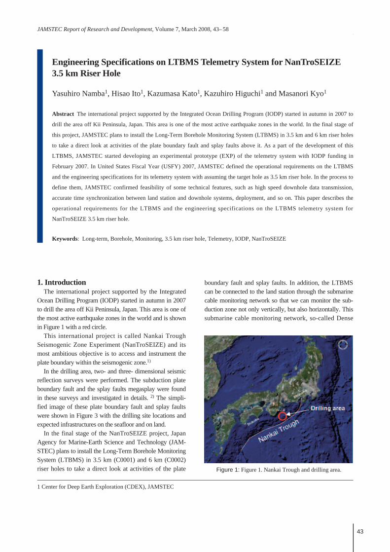
Ocean Drilling Program (IODP) started in autumn in 2007to drill the area off Kii Peninsula, Japan. This area is one ofthe most active earthquake zones in the world and is shownin Figure 1 with a red circle.
This international project is called Nankai TroughSeismogenic Zone Experiment (NanTroSEIZE) and itsmost ambitious objective is to access and instrument theplate boundary within the seismogenic zone.1)
In the drilling area, two- and three- dimensional seismicreflection surveys were performed. The subduction plateboundary fault and the splay faults megasplay were foundin these surveys and investigated in details. 2) The simpli-fied image of these plate boundary fault and splay faultswere shown in Figure 3 with the drilling site locations andexpected infrastructures on the seafloor and on land.
In the final stage of the NanTroSEIZE project, JapanAgency for Marine-Earth Science and Technology (JAM-STEC) plans to install the Long-Term Borehole MonitoringSystem (LTBMS) in 3.5 km (C0001) and 6 km (C0002)riser holes to take a direct look at activities of the plate
1 Center for Deep Earth Exploration (CDEX), JAMSTEC
Figure 1: Figure 1. Nankai Trough and drilling area.
boundary fault and splay faults. In addition, the LTBMScan be connected to the land station through the submarinecable monitoring network so that we can monitor the sub-duction zone not only vertically, but also horizontally. Thissubmarine cable monitoring network, so-called Dense
Engineering Specifications on LTBMS Telemetry System for NanTroSEIZE 3.5 km Riser Hole
JAMSTEC Rep. Res. Dev., Volume 7, March 2008, 43– 5844
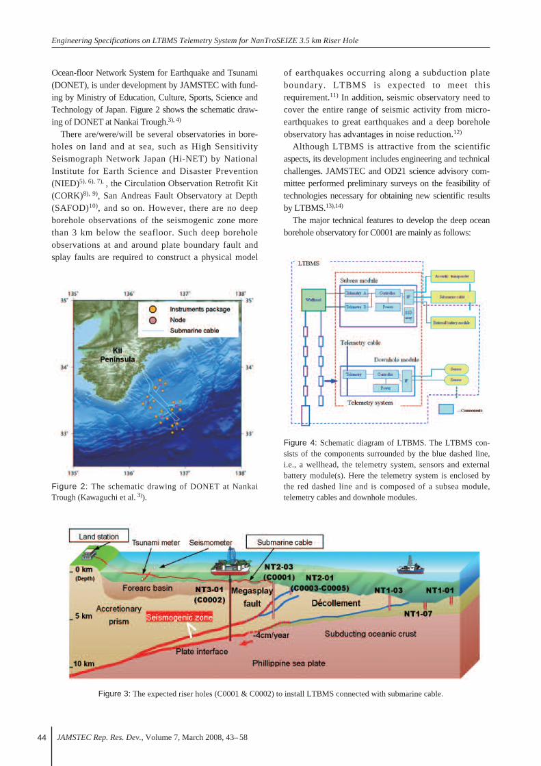
Ocean-floor Network System for Earthquake and Tsunami(DONET), is under development by JAMSTEC with fund-ing by Ministry of Education, Culture, Sports, Science andTechnology of Japan. Figure 2 shows the schematic draw-ing of DONET at Nankai Trough.3), 4)
There are/were/will be several observatories in bore-holes on land and at sea, such as High SensitivitySeismograph Network Japan (Hi-NET) by NationalInstitute for Earth Science and Disaster Prevention(NIED)5), 6), 7), , the Circulation Observation Retrofit Kit(CORK)8), 9), San Andreas Fault Observatory at Depth(SAFOD)10), and so on. However, there are no deepborehole observations of the seismogenic zone morethan 3 km below the seafloor. Such deep boreholeobservations at and around plate boundary fault andsplay faults are required to construct a physical model
of earthquakes occurring along a subduction plateboundary. LTBMS is expected to meet thisrequirement.11) In addition, seismic observatory need tocover the entire range of seismic activity from micro-earthquakes to great earthquakes and a deep boreholeobservatory has advantages in noise reduction.12)
Although LTBMS is attractive from the scientificaspects, its development includes engineering and technicalchallenges. JAMSTEC and OD21 science advisory com-mittee performed preliminary surveys on the feasibility oftechnologies necessary for obtaining new scientific resultsby LTBMS.13),14)
The major technical features to develop the deep oceanborehole observatory for C0001 are mainly as follows:
Figure 3: The expected riser holes (C0001 & C0002) to install LTBMS connected with submarine cable.
Figure 4: Schematic diagram of LTBMS. The LTBMS con-sists of the components surrounded by the blue dashed line,i.e., a wellhead, the telemetry system, sensors and externalbattery module(s). Here the telemetry system is enclosed bythe red dashed line and is composed of a subsea module,telemetry cables and downhole modules.
Figure 2: The schematic drawing of DONET at NankaiTrough (Kawaguchi et al. 3)).
Y. Namba et al.,
JAMSTEC Rep. Res. Dev., Volume 7, March 2008, 43– 58 45
[1] High temperature (target: 125 ºC)[2] Long life (target: 5 years)[3] Complicated deployment (15000 psi wellhead
sys tem,deep well, perforation, packer, mechanical shock)
[4] Method of effective sensor coupling to formation(cement, clamp)
[5] Multilevel monitoring (against 5 spray faults)[6] Multipurpose monitoring (seismic, geodetic,
hydrogeologic), [7] Low power consumption[8] Real-time monitoring (connecting to
submarine cable) and high speed downholedata transmission
[9] Accurate time synchronization between the landstation and downhole sensors,
[10] Wide frequency range/large dynamic rangeof data acquisitions
[11] Down sizing (installing into 9-5/8-in casing with tubing)
[12] System reliability (fault tolerant system).
LTBMS consists of a telemetry system, various sensors,wellhead and external battery module. Figure 4 illustratesthe schematic diagram of the LTBMS. The telemetry sys-tem consists of the subsea module, telemetry cables, anddownhole modules that are surrounded by the red-dashedline in Figure 4. The telemetry system has interfaces (I/F)for sensors, acoustic transponder and submarine cable.
As a part of the development of LTBMS, JAMSTECstarted developing an experimental prototype (EXP) of thetelemetry system with IODP funding in February 2007.
In United States Fiscal Year (USFY) 2007, JAMSTEC
defined the operational requirements on the LTBMS andthe engineering specifications for its telemetry system withassuming the target hole as 3.5 km riser hole in C0001 site.In the process to define them, JAMSTEC confirmed feasi-bility of some technical features, such as high speed down-hole data transmission, accurate time synchronizationbetween the land station and the downhole systems, deploy-ment, and so on.
This paper operational requirements for LTBMS and theengineering specifications on the LTBMS telemetry systemfor NanTroSEIZE 3.5 km riser hole.
2. Scientific Objectives and Observatory PlanOur target NanTroSEIZE riser hole (C0001 site) is
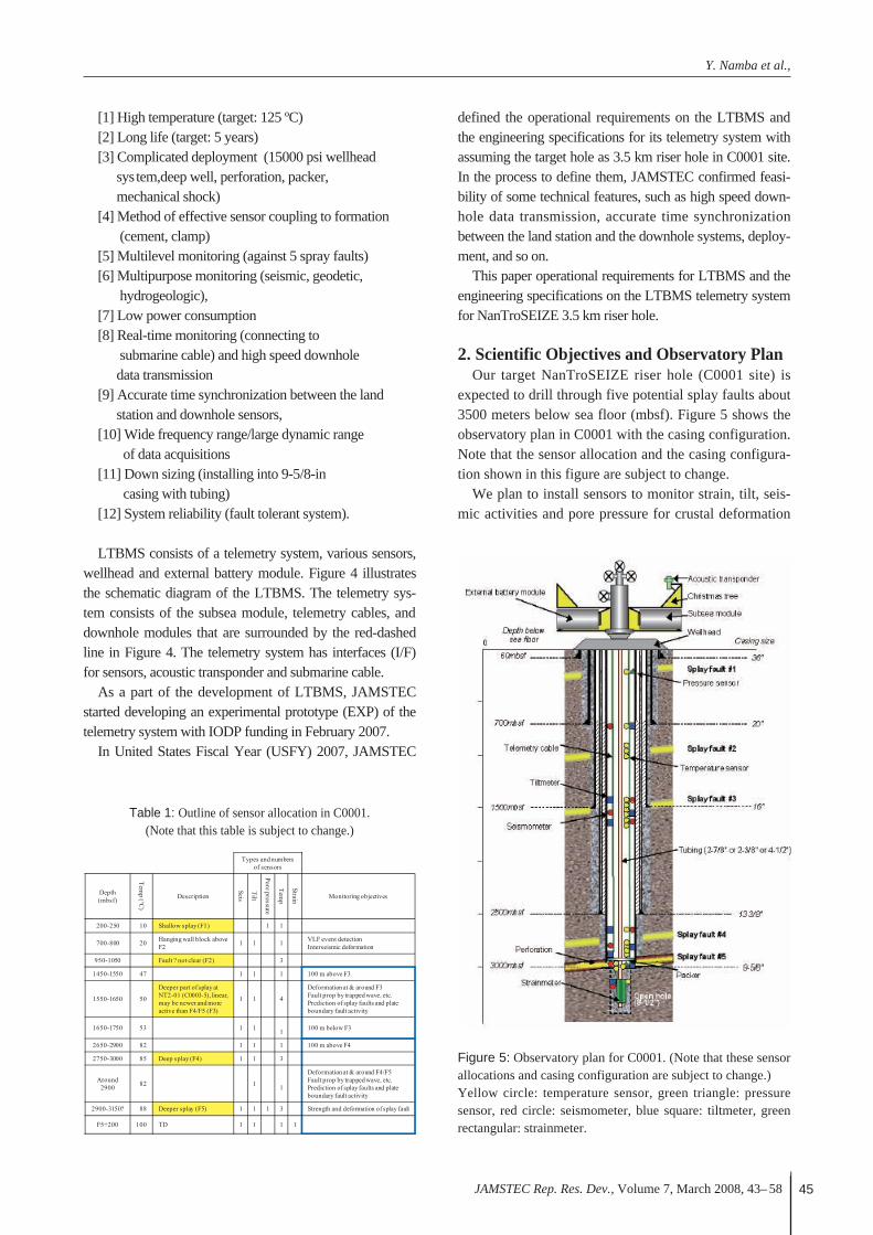
expected to drill through five potential splay faults about3500 meters below sea floor (mbsf). Figure 5 shows theobservatory plan in C0001 with the casing configuration.Note that the sensor allocation and the casing configura-tion shown in this figure are subject to change.
We plan to install sensors to monitor strain, tilt, seis-mic activities and pore pressure for crustal deformation
Table 1: Outline of sensor allocation in C0001.(Note that this table is subject to change.)
Figure 5: Observatory plan for C0001. (Note that these sensorallocations and casing configuration are subject to change.)Yellow circle: temperature sensor, green triangle: pressuresensor, red circle: seismometer, blue square: tiltmeter, greenrectangular: strainmeter.
Engineering Specifications on LTBMS Telemetry System for NanTroSEIZE 3.5 km Riser Hole
JAMSTEC Rep. Res. Dev., Volume 7, March 2008, 43– 5846
at and between splay faults. Seismometer array will beused for micro- and slow- earthquakes detection and forinvestigation of seismic microstructures. Pore pressureand temperature will be monitored for interseismichydrologic state change at the faults. Based on discus-sions with NanTroSEIZE scientists, we tentativelychose five potential splay faults mentioned above andsensors would be located around these fault zones.Summary of sensor allocation and their primary objec-tives are shown in Table 1 with estimated depth andtemperature. Here and hereafter, we call these five splayfaults F1, F2, F3, F4 and F5. Figure 6 is the detailed fig-ure around the open hole.3. Operational Requirements
Because the target riser hole (C0001) would have thetotal depth of about 3500 mbsf under the water depth of2200 m, the deployment of LTBMS itself would be a chal-lenging work.
Center for Deep Earth Exploration (CDEX), JAMSTECinvestigated the methods of installing sensors and relatingrequirements on the equipments and on the installation pro-cedure with considering scientific observatory plan.
This chapter summarizes the results of investigations onsuch operational requirements for the LTBMS.
3.1. Required Primary ComponentsThe following sub-sections describe primary compo-
nents what are required for the LTBMS structure.
3.1.1. TubingTubing is a structural backbone of the LTBMS.
CDEX considers 2-3/8-in, 2-7/8-in and 4-1/2-in tubingwith Premium Joint as candidates to use in 9-5/8-in cas-ing and in 8-1/2-in openhole. While larger size of tubingis preferable for the safe sensor installation, that meanssmaller space around tubing. To decide the tubing size,the following items should be taken into account, i.e.instrument package size, tubing hanger design, comple-tion equipment size, cement plug size, and so on. It ismore desirable for the tubing to have mono-inside diam-eter for the ideal cementing.
3.1.2. Christmas TreeIt is required to prevent materials such as fluids and par-
ticulates from leaking into seawater. Thus we need well-head to seal the hole. Based on the estimated pressure inthe C0001 riser hole and considering the technical feasi-bility of the wellhead tools, CDEX regards the followingspecifications for the Christmas tree would be reasonableto be used in C0001 site.
• Max working pressure : 103.4 MPa (15000 psi). • Electric penetrators : At least 2 for telemetry.• Hydraulic penetrators : At least 3.• Production valves : 2.• Annulus valves : 2.• Docking stations : Several.Here, 2 of hydraulic penetrators are for packer operation
and 1 for fluid sampling. Production valves should matchthe tubing in size. One of docking stations is for a subseamodule and the others for external battery modules.
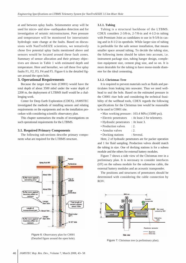
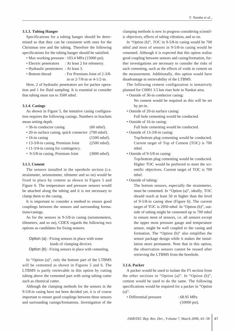
Figure 7 shows a side view of the Christmas tree in apreliminary plan. It is necessary to consider interfaces(I/F) on the subsea module for the submarine cable, theexternal battery modules and an acoustic transponder.
The positions and structures of penetrators should bedetermined with considering the cable connection byROV.
Figure 6: Observatory plan for C0001(Detailed figure around the open hole).
Figure 7: Christmas tree (a preliminary plan).
Y. Namba et al.,
JAMSTEC Rep. Res. Dev., Volume 7, March 2008, 43– 58 47
3.1.3. Tubing HangerSpecifications for a tubing hanger should be deter-
mined so that they can be consistent with ones for theChristmas tree and the tubing. Therefore the followingspecifications for the tubing hanger should be satisfied.
• Max working pressure : 103.4 MPa (15000 psi).• Electric penetrators : At least 2 for telemetry.• Hydraulic penetrators : At least 3.• Bottom thread : For Premium Joint of 2-3/8-
in or 2-7/8-in or 4-1/2-in.Here, 2 of hydraulic penetrators are for packer opera-
tion and 1 for fluid sampling. It is essential to considerthat tubing must run to 3500 mbsf.
3.1.4. CasingsAs shown in Figure 5, the tentative casing configura-
tion requires the following casings. Numbers in bracketsmean setting depth.
• 36-in conductor casing (60 mbsf).• 20-in surface casing, quick connector (700 mbsf).• 16-in casing (1500 mbsf).• 13-3/8-in casing, Premium Joint (2500 mbsf).• 11-3/4-in casing for contingency.• 9-5/8-in casing, Premium Joint (3000 mbsf).
3.1.5. CementThe sensors installed in the openhole section (i.e.
strainmeter, seismometer, tiltmeter and so on) would befixed in place by cement as shown in Figure 5 andFigure 6. The temperature and pressure sensors wouldbe attached along the tubing and it is not necessary toclamp them to the casing.
It is important to consider a method to ensure goodcouplings between the sensors and surrounding forma-tions/casings.
As for the sensors in 9-5/8-in casing (seismometers,tiltmeters, and so on), CDEX regards the following twooptions as candidates for fixing sensors.
Option (a) : Fixing sensors in place with some kinds of clamping devices.
Option (b) : Fixing sensors in place with cementing.
In “Option (a)”, only the bottom part of the LTBMSwill be cemented as shown in Figures 5 and 6. TheLTBMS is partly retrievable in this option by cuttingtubing above the cemented part with using tubing cuttersuch as chemical cutter.
Although the clamping methods for the sensors in the9-5/8-in casing have not been decided yet, it is of courseimportant to ensure good couplings between these sensorsand surrounding casings/formations. Investigation of the
clamping methods is now in progress considering scientif-ic objectives, effects of tubing vibration, and so on.
In “Option (b)”, TOC in 9-5/8-in casing would be 700mbsf and most of sensors in 9-5/8-in casing would becemented. Although it is expected that this option realizegood coupling between sensors and casing/formation, fur-ther investigations are necessary to consider the risks ofsuch cementing, such as the effects of voids in cement onthe measurement. Additionally, this option would havedisadvantage in retrievability of the LTBMS.
The following cement configuration is tentativelyplanned for C0001 3.5 km riser hole in Nankai area.
• Outside of 36-in conductor casing: No cement would be required as this will be setby jet-in.
• Outside of 20-in surface casing:Full hole cementing would be conducted.
• Outside of 16-in casing:Full hole cementing would be conducted.
• Outside of 13-3/8-in casing:Top/bottom plug cementing would be conducted.Current target of Top of Cement (TOC) is 700mbsf.
• Outside of 9-5/8-in casing:Top/bottom plug cementing would be conducted.Higher TOC would be preferred to meet the sci-entific objectives. Current target of TOC is 700mbsf.
• Outside of tubing:The bottom sensors, especially the strainmeter,must be cemented. In “Option (a)”, ideally, TOCshould reach at least 50 m higher than the levelof 9-5/8-in casing shoe (Figure 6). The currenttarget of TOC is 2950 mbsf. In “Option (b)”, out-side of tubing might be cemented up to 700 mbsfto ensure most of sensors, i.e. all sensors exceptthe upper most pressure gauge and temperaturesensor, might be well coupled to the casing andformation. The “Option (b)” also simplifies thesensor package design while it makes the instal-lation more permanent. Note that in this option,the observation sensors cannot be reused afterretrieving the LTBMS from the borehole.
3.1.6. PackerA packer would be used to isolate the F5 section from
the other sections in “Option (a)”. In “Option (b)”,cement would be used to do the same. The followingspecifications would be required for a packer in “Option(a)”.
• Differential pressure : 68.95 MPa(10000 psi).
Engineering Specifications on LTBMS Telemetry System for NanTroSEIZE 3.5 km Riser Hole
JAMSTEC Rep. Res. Dev., Volume 7, March 2008, 43– 5848
• Estimated inside temperature : 4 to 100 ºC• Penetrators for telemetry lines : 2.• Penetrators for hydraulic lines : 7 at Max.Here, 2 of penetrators for hydraulic lines are for pack-
er operations. 5 hydraulic penetrators would be requiredfor the strainmeter at the maximum. The packer wouldbe operated by 2 hydraulic lines and should be retriev-able.
3.1.7. PerforationsWhile it is necessary to isolate the fault zone from the
other formations, pressure measurement section isrequired to have the same pressure as the fault zone has,in order to measure the pore pressure in the fault zone.Perforations can meet this requirement. We investigatedcurrent perforation technologies in the oilfield industry.We found two candidates for a perforation method, i.e.perforations before and after sensor installations.
In the former way, i.e. perforations before sensorinstallation, it’s possible to perforate all around on thecasing. Especially, this would be useful when the forma-tion has directivity.
In the latter way, i.e. perforation after sensor installa-tion, the sensor cable must be avoided in the perforationjob. The current perforating technology is available todetect the cables and safely perforate the casing awayfrom them.
3.1.8. Telemetry CableThe telemetry cable is used for sensor power supply,
data transmission and sensor controls. We are consider-ing two candidates of Permanent Downhole Cable(PDC) for the telemetry cable. One is mono-conductorcable with American Wire Gauge (AWG) #18, and theother is twisted pair cable with AWG#20.
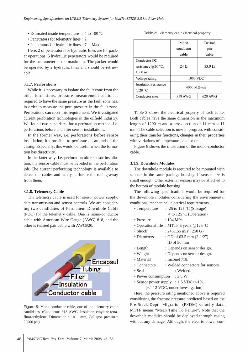
Table 2 shows the electrical property of each cable.Both cables have the same dimension as the maximumlength of 1200 m and a cross-section of 11 mm × 11mm. The cable selection is now in progress with consid-ering their transfer functions, changes in their propertieswith variations of temperature, and so on.
Figure 8 shows the illustration of the mono-conductorcable.
3.1.9. Downhole ModulesThe downhole module is required to be mounted with
sensors in the same package housing, if sensor size issmall enough. Other external sensors may be attached tothe bottom of module housing.
The following specifications would be required forthe downhole modules considering the environmentalconditions, mechanical, electrical requirements.
• Temperature : -25 to 125 ºC (Storage) 4 to 125 ºC (Operation)
• Pressure : 104 MPa • Operational life : MTTF 5 years @125 ºC• Shock : 2451.55 m/s2 (250 G)• Diameters : OD of 63.5 mm (2-1/2”)
ID of 50 mm• Length : Depends on sensor design.• Weight : Depends on sensor design.• Material : Inconel 718.• Connectors : Welded connectors for sensors.• Seal : Welded.• Power consumption : 3.5 W. • Sensor power supply : + 5 VDC+/-1%.
[+/- 12 VDC, under investigation].Here, the pressure rating mentioned above is required
considering the fracture pressure predicted based on thePre-Stack Depth Migration (PSDM) velocity data.MTTF means “Mean Time To Failure”. Note that thedownhole modules should be deployed through casingwithout any damage. Although, the electric power con-
Table 2: Telemetry cable electrical property
Figure 8: Mono-conductor cable, one of the telemetry cablecandidates. (Conductor: #18 AWG, Insulator: ethylene-tetra-fluoroethylene, Dimension :11×11 mm, Collapse pressure:20000 psi)
Y. Namba et al.,
JAMSTEC Rep. Res. Dev., Volume 7, March 2008, 43– 58 49
sumption is specified as 3.5 W in the list, the effort toreduce it must be continued during the detailed design.Sensor power details will be determined through the dis-cussion with sensor developers.
3.1.10. Subsea Module• Temperature : -20 to 70 ºC (Storage)
-5 to 50 ºC (Operation)• Pressure : 35 MPa• Shock : 98 m/s2 (10 G), 11 ms half-sine• Vibration : 25–150 Hz, 49 m/s2 (5 G)• Diameter (ID) : 266.7 mm• Length : 0.61 m• Weight : 34 kg (in seawater)• Mass Storage : 1 Tbyte• Power consumption : 5 W The subsea module should have interfaces for data
transmission and power port. For the data transmission,there are three types of communication; a fast serialcommunication, a slow serial communication andEthernet communication.
3.2. Sensor InstallationWe expect at least 3 types of sensor installations:
• Installation of sensors installed inside the 9-5/8-incasing except the perforated section:
A good cement bond between outside ofthe 9-5/8-in casing and the formation isrequired since the sensors would be fixedinside the casing.
• Installation of sensors at the perforated section ofcasing:
Pore pressure would be measured at theperforations. Therefore, the perforated sectionshould be isolated from the other formationwith packer and/or cement.
• Installation of sensors in the openhole:It is necessary for the strainmeter to be
cemented.Relating to these installations of sensors, it is necessary
to consider the issues mentioned in the following sub-sec-tions.
3.2.1. Cementing EvaluationFor the good quality of LTBMS measurements, the
outside of casings should be well cemented. The cementbond between casings and formations should be evaluat-ed by wireline loggings. Based on these log data, itwould be necessary to adjust the sensor depths.
3.2.2. Sensor Module Coupling to FormationThe sensors would be installed with using a tubing. At
least 2 options of the sensor clamping method are underconsideration as mentioned in the Sub-section 3.1.5. Thesensor installation methods should be carefully investi-gated considering the overall operational plan and sen-sors’ requirements. The operational plan must considerpossible operational difficulties. For example, it is possi-ble that we cannot cement up to the target of TOC.
3.2.3. On-board HandlingOn-board handling equipments would be prepared for
the sensor installation into the well. Although we tentatively chose the sensors to set at
and around splay faults in C0001 riser hole as shown inChapter 2, It would be favorable that the choice andlocations of these sensors would be flexible to optimizethe observation.
Depending where and how the sensors are located,the deployment procedure may be adjusted. The deploy-ment procedure for installing the sensors must be care-fully considered and well planned.
The primary handling equipments are mentionedbelow.
• Cable SpoolersZone 1 explosion proven cable spoolers are
necessary for the cable deployment. These spool-ers would have the function to adjust back ten-sion on cable. Their unit footprint should be assmall as possible.
• Cable SheavesThese sheaves would be used to deploy the
telemetry cables. This means they would treat thecables of 11 mm × 11 mm squared cross section.(See 3.1.8)
• Cable Protector Clamps Cable protector clamps should be designed for
specified tubing. Primary purpose of this clampis to protect and hold the cables onto the tubing .The design must allow that 2 telemetry cablesplus up to 7 additional hydraulic lines can beattached to the tubing. It should be consideredthe clamps might be cemented and also theyshould go through the wellhead without any sig-nificant damage.
• Downhole Module Protector ClampsDownhole module protector clamps would be
designed to protect top and bottom of the down-hole module. Their primary purpose is to protectdownhole module during deployment.
• Splice Protector ClampsThese are the mid joint protectors designed to
protect cable splices. The primary purpose is toprotect the cable splice during deployment.
Engineering Specifications on LTBMS Telemetry System for NanTroSEIZE 3.5 km Riser Hole
JAMSTEC Rep. Res. Dev., Volume 7, March 2008, 43– 5850
• Intellitite Electrical Dry-Mate ConnectorIntellitite electrical dry-mate connectors
would be used for connection between the down-hole module and telemetry cable. There are twooptions for downhole splice. One is a redundantmetal to metal seal deign and the other is an allwelded design. We investigated all weldeddesign for reliability.
• Tubing Hanger Entry GuidesThis should be prepared to avoid cable slack
nearby tubing hanger.• Tubing Centralizers
Primary purpose of centralizers is to centralizetubing inside casing to protect cables and sen-sors. They also provide standoff to optimizecementing. They should be designed not to dam-age the wellhead.
• Tubing Entry GuideA tubing entry guide is installed at the bottom
of the tubing. It provides smooth entry into thewellhead and protects the sensors mounted aboveit. This entry guide may have cementing shoefunctions also.
3.3. Sensor Deployment Operation ProcedureWe are investigating two types of well completion pro-
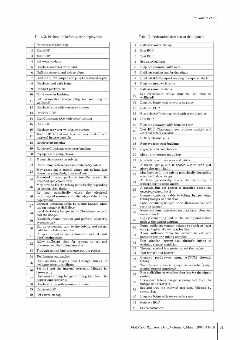
cedure. Main difference between these two procedures isperforation timing, i.e. “Perforation before sensor deploy-ment” and “Perforation after sensor deployment”.
3.3.1. Perforation before Sensor DeploymentThe perforation before sensor deployment is rela-
tively conventional well operation. This operationalprocedure is shown in Table 3. In this case, after per-foration is conducted (corresponding to the 9th line ofTable 3), tubing would be run with sensors andtelemetry cables (the 22nd line of Table 3). This pro-cedure corresponds to “Option (a)” in sub-section3.1.5.
3.3.2. Perforation after Sensor DeploymentThe perforation after sensor deployment corre-
sponds to the “Option (b)” in the sub-section 3.1.5.This option would be relatively good for the couplingbetween the sensors and casings/formations becausein this case, both the outsides of casings and the tub-ing would be cemented. This means the most ofequipments in the downhole such as downhole mod-ules, sensors, and telemetry cables would be cement-ed. Perforation guns would be run in the tubing andthe perforation would be conducted through the tub-ing and casing.
In this case, it is necessary for the operation ofperforation to avoid the downhole modules, sensorsand telemetry cables. For avoiding these downholeequipments, we would rely on Wireline PerforatingPlatform Completion Mapper (WPPCM) that is adirectional perforation tool through tubing and cas-ing not to damage downhole modules, sensors andtelemetry cables.
This operation sequence is shown in Table 4.
4. Fundamental InvestigationsIn order to realize the LTBMS telemetry system, we
selected the following development items as the key issuesto be solved and/or considered.
- Fault tolerant concept- Low power consumption design- System synchronization- High temperature and long life
For the fault tolerance of the system, we need to imple-ment self-diagnostic system that disables a downhole mod-ule if a failure is detected. This safety feature prevents fullsystem malfunction. We verified our design concept bymaking mockup and testing this feature.
For the low power consumption design of the telemetrysystem, we need to select low-power components anddevelop power management system.
In order to collect the real-time data obtained at someexact time, we need to select high accurate clock and con-firm telemetry synchronization accuracy improvement. Thisis important to satisfy seismic data acquisition requirement.
It is important to design the telemetry hardware to makethe system survived at 125°C for five years. We investigat-ed some high temperature tools designed for downholeenvironment to see whether we can use some of their com-ponents for the telemetry system.
This chapter describes summaries of what has beeninvestigated in FY07 regarding the key issues mentionedabove except the last issue. (As for the “high temperatureand long life” issue, we plan this issue mainly inUSFY2008. We did preliminary investigation based on thedatabase.)
4.1. Fault Tolerant SystemFault tolerant system distinguishes faults by itself and
maintains its health. This system is able to detect faults atsystem power up and during monitoring. If the systemdetects a fault, the system automatically switches to thebackup telemetry or change configuration to minimizeaffected section. The subsea module has a redundant sys-tem and the downhole telemetry system has a special con-figuration for fault tolerant function.
Y. Namba et al.,
JAMSTEC Rep. Res. Dev., Volume 7, March 2008, 43– 58 51
Table 4: Perforation after sensor deploymentTable 3: Perforation before sensor deployment

Engineering Specifications on LTBMS Telemetry System for NanTroSEIZE 3.5 km Riser Hole
JAMSTEC Rep. Res. Dev., Volume 7, March 2008, 43– 5852
Figure 9: Subsea module block diagram.
Table 7: Downhole module electronics power consumption
Table 8: Downhole module telemetry power consumption break-down
Figure 10: Downhole module block diagram.
Table 5: Subsea electronics power consumption
Table 6: Subsea telemetry power consumption break-down(except DSP and FPGA)
Y. Namba et al.,
JAMSTEC Rep. Res. Dev., Volume 7, March 2008, 43– 58 53
In USFY07, CDEX carried out experiments on the faulttolerance of the telemetry system. We made a model ofthe telemetry system with one model of the subsea mod-ule, four models of the downhole modules and the teleme-try cables. In the experiments, we generated artificial openand short circuits at one of downhole modules or in one ofthe telemetry cables. These artificial failures could bedetected by the fault tolerant system and the failed mod-ules were disabled by the system successfully. As a result,it is confirmed that our concept of the fault tolerant systemis feasible.
4.2. Low Power ConsumptionAs mentioned in Chapter 1, the LTBMS can be con-
nected to DONET. In this case, DONET suppliesenergy for the LTBMS. When the LTBMS is discon-nected from DONET for a certain reason, the LTBMScan continue monitoring with its own external batter-ies. In either case, the electricity supply for theLTBMS is strictly limited. Therefore, it is necessaryto select low-power components and develop powermanagement system.
With using the same telemetry model that was used forthe experiments on fault tolerance, we performed anotherexperiment to confirm the feasibility of the power man-agement system. Here the power management systemwould have functions of selecting arbitrary downholemodule and doing ON/OFF control with sending a signalfrom the subsea module. These functions were successful-ly validated in the experiment.
As for consideration to low power components, it isimportant to estimate the power consumption of thetelemetry system in the case that the system would becomposed with the current technology. The following sub-sections mention the theoretically and experimentally esti-mated power consumptions.
4.2.1. Subsea Module Power ConsumptionSubsea module block diagram is shown in Figure 9.The power consumption of the subsea telemetry com-
ponents is summarized in Table 5. The power consump-tion of Digital Signal Processor (DSP) and FieldProgrammable Gate Array (FPGA) had been estimatedbased on the feasibility test results. A break-down ofthe power consumption of the electronics except DSPand FPGA are shown in Table 6.
For the design of EXP (Experimental Prototype) ofthe LTBMS, the number of DSP should increase from 2to 6 because of redundancies. Therefore, without opti-mization between the data transmission speed the powerconsumption, requirement will increase accordingly.
The subsea module power consumption is estimatedto be 4.32 W. The proposed target specification is 5 W.
4.2.2. Downhole Module Power ConsumptionDownhole module block diagram is shown in Figure 10.The estimated downhole module power consumption
is 3.37 W as shown in Table 7. The proposed targetspecification is 3.5 W.
The power consumption of the downhole moduletelemetry except DSP and FPGA is estimated around830 mW from the specifications of components. Themodification of the electronics configuration of themodule is small therefore the power consumption ofthe EXP module will be almost the same. The exter-nal sensor power consumption was assumed as 1 Wfor all the downhole modules. 125 mW was distrib-uted to each module (125 mW= 1000 mW/8mod-ules).
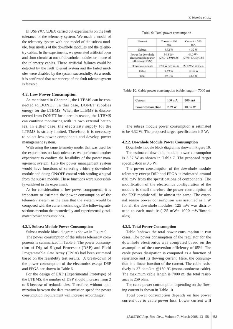
4.2.3. Total Power ConsumptionTable 9 shows the total power consumption in two
cases. The power consumption of the regulator for thedownhole electronics was computed based on theassumption of the conversion efficiency of 85%. Thecable power dissipation is computed as a function ofresistance and its flowing current. Here, the consump-tion is a linear function of the current. The cable resis-tively is 37 ohm/km @150 ºC (mono-conductor cable).The maximum cable length is 7000 m; the total resist-ance is 259 ohm.
The cable power consumption depending on the flow-ing current is shown in Table 10.
Total power consumption depends on line powercurrent due to cable power loss. Lower current will
Table 9: Total power consumption
Table 10: Cable power consumption (cable length = 7000 m)
Engineering Specifications on LTBMS Telemetry System for NanTroSEIZE 3.5 km Riser Hole
JAMSTEC Rep. Res. Dev., Volume 7, March 2008, 43– 5854
save cable power loss. On the other hand, lower cur-rent requires higher voltage for the downhole moduleto draw power at module. Based on this total powerestimation, “100 mA drive” requires 348 V and “200mA drive” requires 220 V at constant current regulatorin the subsea module. Higher voltage power supplyrequire higher voltage resistance component that isless efficiency in general. In addition voltage up con-verter consumes more power to generate higher volt-age. From these design items, we need to consider effi-ciency of constant current regulator and loss in thecable to define optimum drive current for the best effi-ciency.
4.2.4. Power Management ScenarioThis is provisory case study of power management
based on Table 9 power consumption estimation. Wehave not concluded yet but we will tentatively assume100 mA drive for this case study.
♦ Senario1:The LTBMS would be operated with only DONET
cable power (30 W). To have communication withDONET cable, we need Opt/Elec converter thatwould require 3 W. So available power for the down-hole is
30 (DONET power) – 4.32 (subsea power)– 3 (Opt/Elec converter) – 2.59 (cable loss)
= 20.09 W
This power is enough only for 5 downhole modules.So the number of downhole modules must be reducedto drive with the available power (30 W). Or we mustuse external battery power to drive the full system.
♦ Senario2:The LTBMS would be operated with DONET and
external battery for 1-year period. Required powerfor the LTBMS is 39.1 W (Table 9) and Opt/Elecconverter (3 W).
39.1 + 3 – 30 = 12.1 W
It is necessary that the external battery supplies 12.1W to maintain operation for 1-year (8760 hours), sototal required power for the battery is 106 kWh.
♦ Senario3:Without DONET cable, the LTBMS would be
operated for 2 months only with battery power. Forthis case Opt/Elec converter is not necessary. So thetotal necessary power can be calculated as follows.
39.1 × 1440 hours (2 months, 60 days)= 56304 Wh
♦ Senario4:If we employ the Subsea Monitor Control (SMC)
package as battery pack and use ELECTROCHEMBCX85 series TSD battery, one SMC module canstore 14.9 kWh. Based on this condition, we can keepthe full operation of the LTBMS for 15 days because
14934 / 39.1 = 381 hours.
To keep the full-operation for 2 months only withbattery packs, the following calculation
56304 / 14934 ≈ 4,
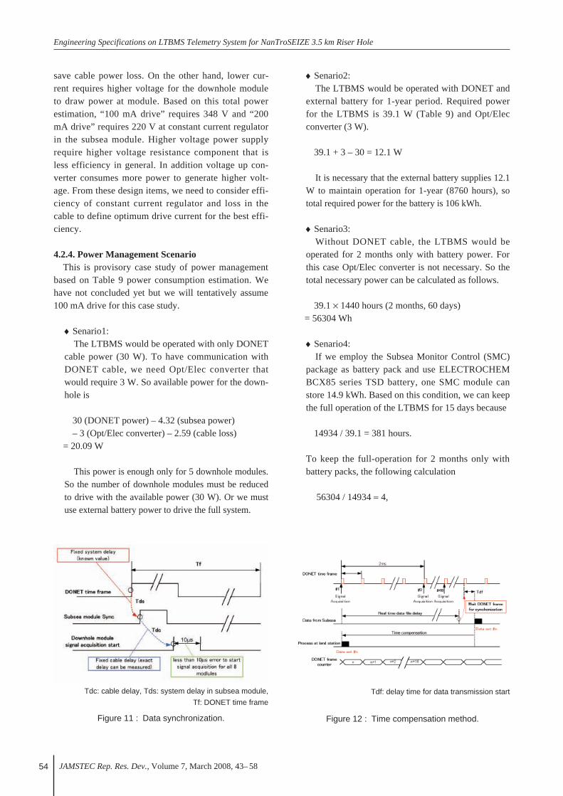
Tdc: cable delay, Tds: system delay in subsea module,
Tf: DONET time frame
Figure 11 : Data synchronization.
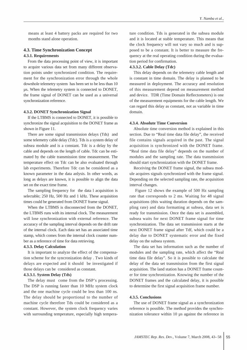
Tdf: delay time for data transmission start
Figure 12 : Time compensation method.
Y. Namba et al.,
JAMSTEC Rep. Res. Dev., Volume 7, March 2008, 43– 58 55
means at least 4 battery packs are required for twomonths stand alone operation.
4.3. Time Synchronization Concept4.3.1. Requirements
From the data processing point of view, it is importantto acquire various data set from many different observa-tion points under synchronized condition. The require-ment for the synchronization error through the wholedownhole telemetry system has been set to be less than 10µs. When the telemetry system is connected to DONET,the frame signal of DONET can be used as a universalsynchronization reference.
4.3.2. DONET Synchronization SignalIf the LTBMS is connected to DONET, it is possible to
synchronize the signal acquisition to the DONET frame asshown in Figure 11.
There are some signal transmission delays (Tds) andsome telemetry cable delay (Tdc). Tds is a system delay ofsubsea module and is a constant. Tdc is a delay by thecable and depends on the length of cable. Tdc can be esti-mated by the cable transmission time measurement. Thetemperature effect on Tdc can be also evaluated throughlab experiments. Therefore Tdc can be considered as aknown parameter in the data anlysis. In other words, aslong as delays are known, it is possible to align the dataset on the exact time frame.
The sampling frequency for the data l acquisition isselectable; 250 Hz, 500 Hz and 1 kHz. These acquisitiontimes could be generated from DONET frame signal.
When the LTBMS is disconnected from the DONET,the LTBMS runs with its internal clock. The measurementwill lose synchronization with external reference. Theaccuracy of the sampling interval depends on the drift rateof the internal clock. Each data set has an associated timestamp, which comes from the internal clock counter num-ber as a reference of time for data retrieving. 4.3.3. Delay Calculation
It is important to analyze the effect of the compensa-tion scheme for the syncronization delay . Two kinds ofdelays are expected and it should be investigated ifthose delays can be considered as constant. 4.3.3.1. System Delay (Tds)
The delay must come from the DSP’s processing.The DSP is running faster than 10 MHz system clockand the one machine cycle could be less than 100 ns.The delay should be proportional to the number ofmachine cycle therefore Tds could be considered as aconstant. However, the system clock frequency varieswith surrounding temperature, especially high tempera-
ture condition. Tds is generated in the subsea moduleand it is located at stable temperature. This means thatthe clock frequency will not vary so much and is sup-posed to be a constant. It is better to measure the fre-quency at the real operating condition during the evalua-tion period for confirmation.4.3.3.2. Cable Delay (Tdc)
This delay depends on the telemetry cable length andis constant in time domain. The delay is planned to bemeasured in deployment. The accuracy and resolutionof this measurement depend on measurement methodand device. TDR (Time Domain Reflectometers) is oneof the measurement equipments for the cable length. Wecan regard this delay as constant, not as variable in timedomain.
4.3.4. Absolute Time ConversionAbsolute time conversion method is explained in this
section. Due to “Real time data file delay”, the receivedfile contains signals acquired in the past. The signalacquisition is synchronized with the DONET frame.“Real time data file delay” depends on the number ofmodules and the sampling rate. The data transmissionshould start synchronization with the DONET frame.
Receiving the DONET frame signal, the subsea mod-ule acquires signals synchronized with the frame signal.Depending on the selected sampling rate, the acquisitioninterval changes.
Figure 12 shows the example of 500 Hz samplingrate that corresponds to 2 ms. Waiting for 48 signalacquisitions (this waiting duration depends on the sam-pling rate) and data formatting at subsea, data set isready for transmission. Once the data set is assembled,subsea waits for next DONET frame signal for timesynchronization. The data set transmission starts at thenext DONET frame signal after Tdf, which could be adelay due to DONET systematic error and the fixeddelay on the subsea system.
The data set has information such as the number ofmodules and the sampling rate, which affect the “Realtime data file delay”. So it is possible to calculate thedelay of the data set transmission from the first signalacquisition. The land station has a DONET frame count-er for time synchronization. Knowing the number of theDONET frames and the calculated delay, it is possibleto determine the first signal acquisition frame number.
4.3.5. ConclusionsThe use of DONET frame signal as a synchronization
reference is possible. The method provides the synchro-nization tolerance within 10 µs against the reference in
Engineering Specifications on LTBMS Telemetry System for NanTroSEIZE 3.5 km Riser Hole
JAMSTEC Rep. Res. Dev., Volume 7, March 2008, 43– 5856
the land station by eliminating known delays. The exactdelay must be measured during the fabrication andimplementation phase and the delay must be clarified.
5. Engineering Specifications for theTelemetry System
On one hand, the telemetry system should meet therequirements on the long-term borehole monitoring as muchas possible so that we can achieve the goal of constructing aphysical model of earthquakes and a real-time monitoringnetwork; on the other, there are many technological, engi-neering and operational to develop and produce the system.CDEX identified the engineering specifications on thetelemetry system considering the trade-offs among them.
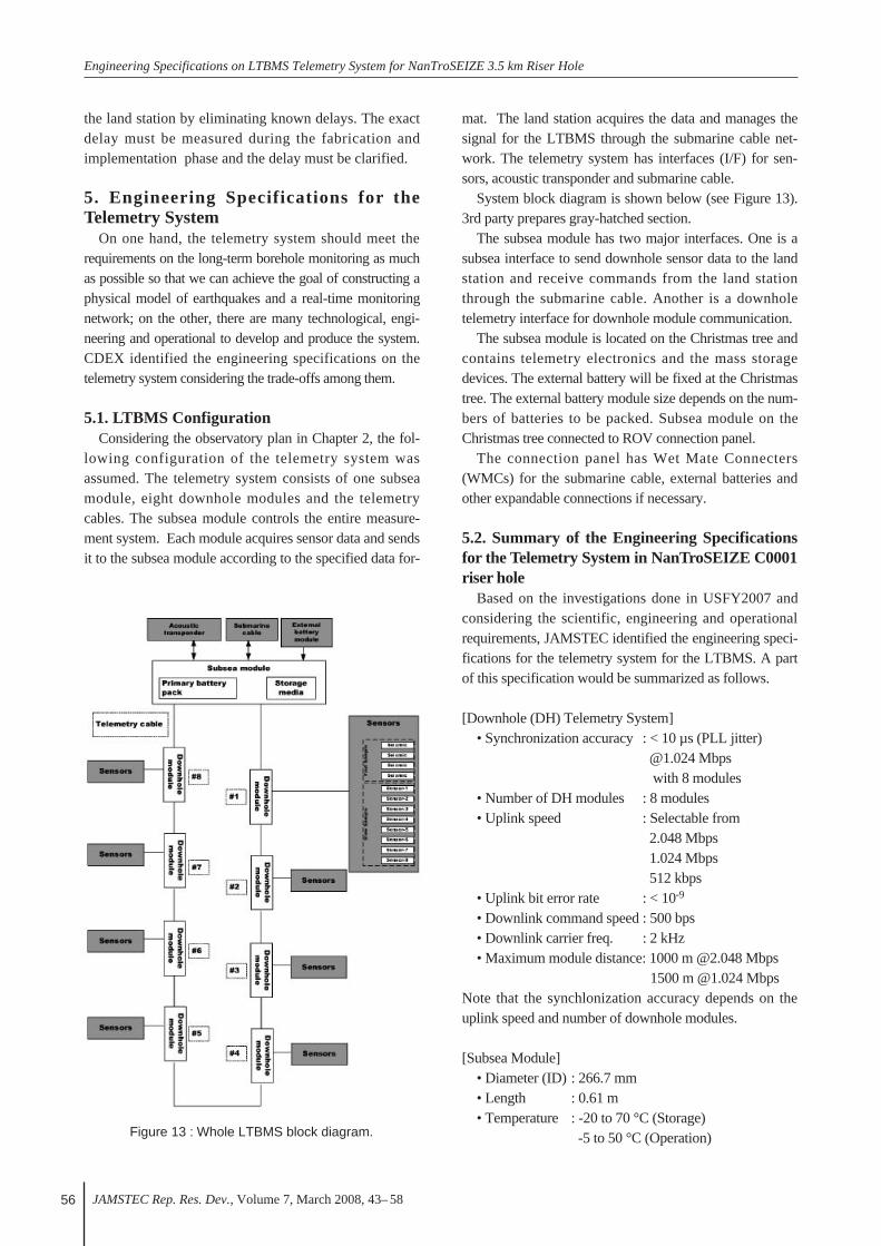
5.1. LTBMS ConfigurationConsidering the observatory plan in Chapter 2, the fol-
lowing configuration of the telemetry system wasassumed. The telemetry system consists of one subseamodule, eight downhole modules and the telemetrycables. The subsea module controls the entire measure-ment system. Each module acquires sensor data and sendsit to the subsea module according to the specified data for-
mat. The land station acquires the data and manages thesignal for the LTBMS through the submarine cable net-work. The telemetry system has interfaces (I/F) for sen-sors, acoustic transponder and submarine cable.
System block diagram is shown below (see Figure 13).3rd party prepares gray-hatched section.
The subsea module has two major interfaces. One is asubsea interface to send downhole sensor data to the landstation and receive commands from the land stationthrough the submarine cable. Another is a downholetelemetry interface for downhole module communication.
The subsea module is located on the Christmas tree andcontains telemetry electronics and the mass storagedevices. The external battery will be fixed at the Christmastree. The external battery module size depends on the num-bers of batteries to be packed. Subsea module on theChristmas tree connected to ROV connection panel.
The connection panel has Wet Mate Connecters(WMCs) for the submarine cable, external batteries andother expandable connections if necessary.
5.2. Summary of the Engineering Specificationsfor the Telemetry System in NanTroSEIZE C0001riser hole
Based on the investigations done in USFY2007 andconsidering the scientific, engineering and operationalrequirements, JAMSTEC identified the engineering speci-fications for the telemetry system for the LTBMS. A partof this specification would be summarized as follows.
[Downhole (DH) Telemetry System]• Synchronization accuracy : < 10 µs (PLL jitter)
@1.024 Mbps with 8 modules
• Number of DH modules : 8 modules• Uplink speed : Selectable from
2.048 Mbps1.024 Mbps512 kbps
• Uplink bit error rate : < 10-9
• Downlink command speed : 500 bps• Downlink carrier freq. : 2 kHz• Maximum module distance: 1000 m @2.048 Mbps
1500 m @1.024 MbpsNote that the synchlonization accuracy depends on theuplink speed and number of downhole modules.
[Subsea Module]• Diameter (ID) : 266.7 mm• Length : 0.61 m• Temperature : -20 to 70 °C (Storage)
-5 to 50 °C (Operation)Figure 13 : Whole LTBMS block diagram.
Y. Namba et al.,
JAMSTEC Rep. Res. Dev., Volume 7, March 2008, 43– 58 57
• Pressure : 35 MPa• Shock : 98 m/s2 (10 G)
11 ms half-sine *IWIS compliant (ISO 13628-6)
• Module weight : 34 kg (in seawater with flotation)
• Power consumption : 5 W• Mass storage size : 1 Tbyte• Subsea I/F for electric power supply:
2 kinds of port (Submarine cable / additional battery port)
• Subsea interfaces for data transmission: 3 kinds of port(RS-232C, RS-422 , Ethernet)
• High speed analog signal input (seismic ch): 4 ch / module (Voltage proportional to signal)
• Dynamic range : 120 dB (A/D 24 bit ∆ΣMinimum phase)
• Frequency range : 0 to 400 Hz• Pre-amplifier
Input voltage range : 5 Vpp (differential)Input impedance : >10 Mohm
• Low speed analog signal input: 8 ch / module (Voltage proportional to signal)
Dynamic range: > 97 dB @10 Hz SamplingFrequency range: 0 to 8 Hz (Upper freq. limit depends on sampling rate)Drift : 50 ppm (1000 hours)Pre-amplifierInput voltage range: -2.5 V ~ +2.5 VInput impedance : > 10 Mohm
[Downhole Module]• Diameter (OD) : 63.5 mm• Diameter (ID) : 50 mm• Length : Depends on sensor design• Module weight : Depends on sensor design• Temperature : -25 to 125 °C (Storage)
4 to125 °C (Operation)• Pressure : 104 MPa • Operational life: MTTF 5 years @125 °C• Shock : 2451.55 m/s2 (250 G)
*Able to deploy through casing without damage
• Material : Inconel 718• Connection for sensors : Welded connector • Seal : Welded • Power consumption : 3.5 W• Sensor power supply :+ 5 VDC+/-1%
[+/- 12 VDC, under investigation]• High speed analog signal input (seismic ch)
4 ch / module (Voltage proportional to signal)
Dynamic range : 120 dB (A/D 24 bit ∆Σ Minimum phase)
Frequency range : 0 to 400 HzPre-amplifier
Input voltage range : 5 Vpp (differential)Input impedance : >10 Mohm
• Low speed analog signal input8 ch / module (Voltage proportional to signal)Dynamic range : > 97 dB @ 10 Hz samplingFrequency range : 0 to 8 Hz
*Upper frequency limit depends on sampling rate
Drift : 50 ppm (1000 hours)Pre-amplifier
Input voltage range : -2.5 V ~ +2.5 VInput impedance : > 10 Mohm
• Digital input :RS-232C, RS-485, SPI (Optional)Command out for sensor : 4 bits
(15 kinds of command)Command in for status monitor : 8 bits
6. ConclusionsThis paper reports the results of works in USFY 2007
for the development of the telemetry system. InUSFY2007, the engineering specifications for thetelemetry system were defined considering the scientif-ic objectives, observatory plan, engineering require-ments and operational requirements. In the process todefine the specifications, some experimental and theo-retical studies were carried out. The observatory planwas made and the operational requirements on theLTBMS were defined based on the operational plan.Some fundamental investigations were performed and inthese investigations, some power consumption scenarioswere studied. Feasibilities of the fault tolerant system,system synchronization, and so on were confirmed.
Based on the engineering specifications and relatingstudies what are described in this paper, JAMSTEC plans tofabricate an EXP of the telemetry system and carry out anexperiment in a borehole on land in USFY 2009.
Acknowledgements This paper is based on the results of works done in
USFY 2007 in the telemetry development project support-ed by the IODP Management International, Inc., for theIntegrated Ocean Drilling Program under the sponsorshipof the U.S. National Science Foundation, the Ministry ofCulture, Education, Sports, Science and Technology ofJapan, and other participating countries. We thank IODPand Engineering Task Force (ETF) members for financialsupport and thoughtful reviews. Here we denote that a partof works was done by LTBMS project team in

Engineering Specifications on LTBMS Telemetry System for NanTroSEIZE 3.5 km Riser Hole
JAMSTEC Rep. Res. Dev., Volume 7, March 2008, 43– 5858
Schlumberger K. K. (SKK) through outsourcing. Weexpress thanks for SKK’s efforts. We appreciateTechnical Committee members for their thoughtfulreviews and helpful comments. We also would like toexpress our thanks to Dr. Araki (JAMSTEC) for informa-tion of DONET, strain meter, and so on.
References1) H. Tobbin and M. Kinoshita, “The IODP Nankai Trough
Seismogenic Zone Experiment”, Scientific Drilling, Special
Issue No.1, 39-41 (2007).
2) G. F. Moore, et al., “Three- Dimensional Splay Fault
Geometry and Implications for Tsunami Generation”, SCI-
ENCE volume 318, 1128-1131 (2007).
3) K. Kawaguchi, et al., “Seafloor Infrastructure for High
Density Earthquakes and Tsunamis Monitoring”, Proc. of
Int. Workshop on Marine Tech., [CD-ROM] KK037 (2007).
4) S. Kaneko, et al., “Installation requirements for seismic
observation in the seafloor”, Proc. of Int. Workshop on
Marine Tech., [CD-ROM] SK068 (2007).
5) K. Obara, “Hi-net: High Sensitivity Network, Japan,” Lecture
Notes in Earth Sciences, vol. 98, pp.79-87, 2002
6) Y. Okada, et al., “Recent progress of seismic observation net-
work in Japan --- Hi-net, F-net, K-net and KiK-net ---,”
Earth Planets Space, 56, pp.xv-xxviii, 2004.
7) K., Obara, et al., “A densely distributed high-sensitivity seis-
mograph network in Japan: Hi-net by National Research
Institute for Earth Science and Disaster Prevention,” Rev.
Sci. Instruments, 76, pp. (021301-1)-(021301-12), 2005.
8) K. Becker, et al., “The CORK Experiment in hole 949C:
Long-Term Observations of Pressure and Temperature in
the Barbados Accretionary Prism”, Proceedings of the
Ocean Drilling Program, Scientific Results, Vol. 156, 247-
252, (1997).
9) M. Kastner, et al., “New insight into the hydrology of the
ocean crust through long-term monitoring,” Oceanography,
Vol. 19, No. 4, pp.46-57, 2006.
10) S. Hickman, et al., “Structure and Properties of the San
Andreas Fault in Central California: Recent Results from
SAFOD Experiment,” Sci. Drill., Special Issue No.1, pp.29-
32, 2007.
11) H. Ito, “Long-term monitoring in deep boreholes in the
Nankai subduction zone,” Sci. Drill., Special Issue, No.1,
pp.117-119, 2007.
12) E. Araki, et al., “Improvement of seismic observation in the
ocean by use of seafloor boreholes”, Bull. Seismol. Soc.
Amer., Vol. 94, 678-690 (2004).
13) Center for Deep Earth Exploration (CDEX), Long Term
Borehole Monitoring System High Level Design Document,
IODP-MI (2006).
14) M. Shinohara, et al., “Long-Term Monitoring Using Deep
Seafloor Boreholes Penetrating the Seismogenic Zone”, Bull.
Earthq. Res. Inst. Univ. Tokyo, Vol. 78, 205-218 (2003).
(Received December 15, 2007)