so-z.. 7 · l>mr0I Date R:Hi9Unl'RY DOCKET HLE
210
SEP TOPIC: III-4.B, TURBINE MISSILES Response to D. Persiriko For Addl Info Received wth ltr dtd 02/24/82 THE ATTACHED FILES ARE OFFICIAL RECORDS OF THE DIVISION OF DOCUMENT CONTROL. THEY HAVE BEEN CHARGED TO YOU FOR A LIMITED TIME PERIOD AND MUST BE RETURNED ·TO THE RECORDS . FACILITY BRANCH 016. PLEASE DO NOT SEND DOCUMENTS CHARGED OUT THROUGH THE MAIL. REMOVAL OF ANY PAGE(S) FROM DOCUMENT FOR REPRODUCTION MUST BE REFERRED TO FILE PERSOl)!NE.L. · . :.it,r;!rnt # so- z.. .3 7 · l>mr0I fl DEADLINE RETURN DATE Date o-z.--z..t.1..-SZkf fJDCU!Hfl. R:Hi9Unl'RY DOCKET HLE RECORDS FACILITY BRANCH
Transcript of so-z.. 7 · l>mr0I Date R:Hi9Unl'RY DOCKET HLE
SEP TOPIC: III-4.B, TURBINE MISSILES
Response to D. Persiriko R~quest For Addl Info
Received wth ltr dtd 02/24/82
~NOTICE~ THE ATTACHED FILES ARE OFFICIAL RECORDS OF THE DIVISION OF DOCUMENT CONTROL. THEY HAVE BEEN CHARGED TO YOU FOR A LIMITED TIME PERIOD AND MUST BE RETURNED ·TO THE RECORDS . FACILITY BRANCH 016. PLEASE DO NOT SEND DOCUMENTS CHARGED OUT THROUGH THE MAIL. REMOVAL OF ANY PAGE(S) FROM DOCUMENT FOR REPRODUCTION MUST BE REFERRED TO FILE PERSOl)!NE.L.
· . :.it,r;!rnt # so- z.. .3 7 · l>mr0I fl &7..-o~oz..o4to
DEADLINE RETURN DATE Date o-z.--z..t.1..-SZkf fJDCU!Hfl. R:Hi9Unl'RY DOCKET HLE
RECORDS FACILITY BRANCH
, ' -·
Revision 5 Issued April 16, 1975
A. MAIN TURBINE-
B. REFERENCES
1. Design Documents
a. P&ID; M-12, 13, 15, 21, 22, 37, 41, 42, 43
b. Electrical Schematics; 12E2358 thru 2365
2. Dresden Equipment Manual, GEK 786
a. Chapter 12
•• b. Chapter 33-5600.
3. Dresden FSAR
a. Section 4.4.3
b; Sec.tion 11
4. Video Tapes; 6101 (M-406, 407, 410, 433, 398, 399)*
5. Manuals
- a. Steam Turbine-Generator, GEK-5551
• 1) Volume I
a) Sections 6, 8, 9, 11, 12, 14
2) Volume III
a) Section 49
• *Instructor Reference
_REGULATORY DOCKET FILE COt¥
GENERAL. ELECTRIC
•
• e
B. 5~ Manuals (Continued)
b. Large Steam Turbine-Generator Training Manual, I&SE
1) Sections 3, 4, 5~ 10, 11
C. OBJECT IVES
1. General Description
2. Flow Paths; Steam and Auxiliaries
3. Major Components
4. Auxiliary Systems
5. Turbine Trips
6. Reactor Scrams Originating with the Turbine
7. Technical Specifications Associated with Turbine and Auxiliaries
D. BRIEF DESCRIETION
1. Purpose:
To convert thermodynamic energy of the reactor steam into mechanical energy to drive the main generator.
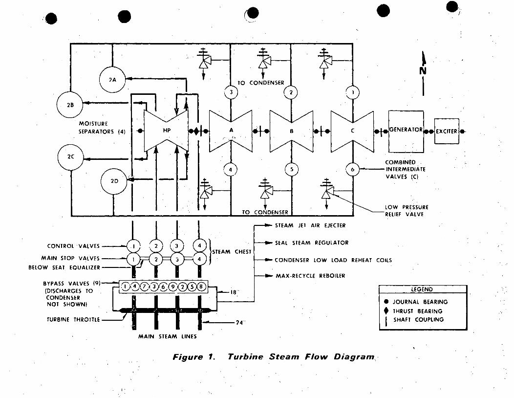
2. Basic Description (Figure 1)
a •. One high pressure (HP) section
b. Three low pressure (LP) sections identified consecutively as A, ·B, and C from the HP section to the generator
c. · 18'00 rpm
- 2 -
(__ :
(.
(_ ..
•
D. 2. Basic Description (Figure 1) (Continued)
d. Tandem-compound, Six-flow
1) Tandem-compound means that each section is aligned on the same shaft and that steam leaves the HP section before expansion is complete and then goes through one or more LP sections.
2) Six-flow means that the steam enters at the middle of the LP turbines and flows in both directions.
e. Non-reheat; steam is not reheated before returning to LP turbines.
f. Last stage buckets in the low pressure turbine are 38".
g. ·Approximate steam conditions:
·.1)
2)
3)
4)
950 psig throttle pressure at
6 9.8 x 10 lb./hr. steam flow with
0.28% moisture against a maximum
Back pressure of 1.5" Hg in the main condenser.
3. Steam Flow Path (Figure 2)
a. .From four main steam lines (24") to.
b. .Turbine throttle (24")
c .• · :18 11 lines· to ·bypass valves from throttle.
1) Max-Recycle reboiler
2) Condenser low load rehe.at coils
3) Seal steam regulator
4) Steam jet air ejector regulator
5) Bypass-valves (40% capacity provided by 9 valves)
d. Through main stop valves to
e •. Steam che~t (that are·a below the seats of tQ.e main stop valves to the control valve seats).
- 3 -
·'
D.
•
•• E.
3. Steam Flow Path (Figure 2) (Continued)
f. Through the control valves
g. Through the high pressure turbine
h. Exhausts to the moisture separators (4)
i. Dried steam is admitted to the low pressure turbine through six combined intermediate valves (CIV' s).
j. Low pressure turbine exhausts to the main condenser.
k. Extraction steam is drawn from var'ious low pressure stages for feedwater heaters.
4. Other Tandem Mounted Components
a. Generator, a four pole., 920 MVA at .9 power factor, hydrogen cooled with liquid stator coolant
b. Exciter, a four pole,. 1905 kVA, air cooled
=· Other Components
a. Low pressure relief valves
1) Set at 275 psig
2) Protect the LP turbine casing if the main stop valves suddenly~ shut.
b. Bearings
1) Twelve spherical seat journal bearings
2) A tapered-land thrust bearing mounted at the fixed middle standard .
. .·.
COMPONENT DESCRIPTION
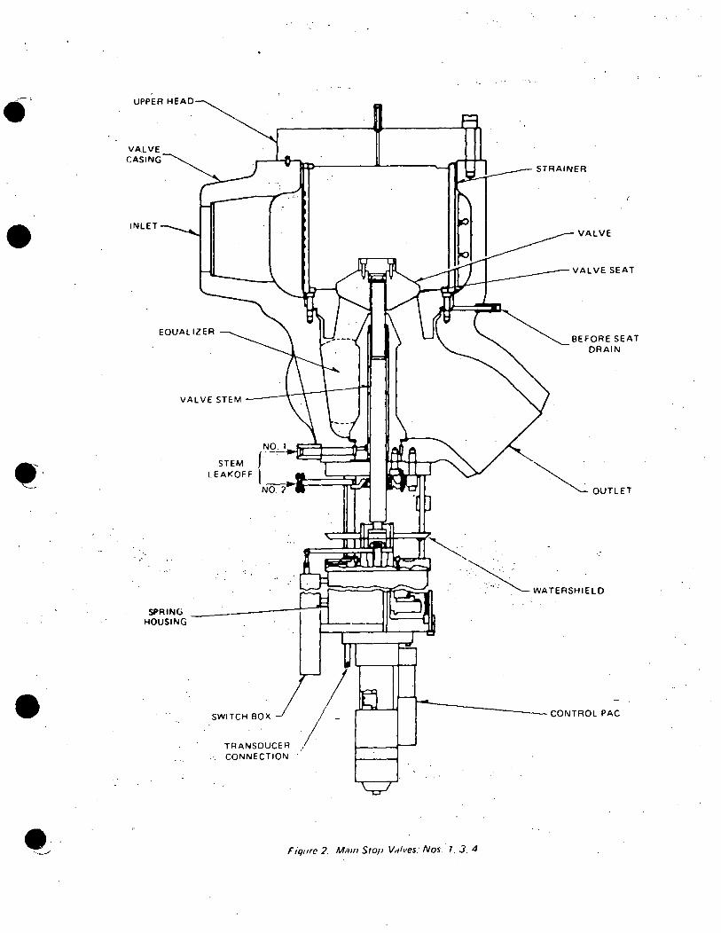
· 1. Turbine Stop Valves (Figure 2)
a. Quantity is 4.
(
c-·
e ( - 4 -
. ,
E. 1. Turbine Stop Valves (Figure 2) (Continued)
b. Purpose:
·These are emergency valves and function to protect the turbine from overspeed resulting from:,
.·'·
Failure of the control valves or,
• · Generator trip.
•
c. Cons true tion
1) All four stop valves are welded together at the below-seat equalizer and thus have interconnected flow paths .•
2) Each valve is controlled by an operator at the bottom of the valve via the Electro Hydraulic Control System (EHC).
3) Hydraulically operated open and closed, spring loaded closed. ·'.
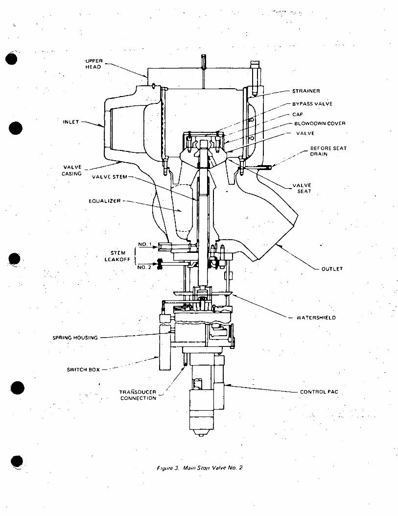
4) Valve Number 2: (Figure .3)
a) Has an internally mounted.pilot valve used for admitting steam to warm the steam chest •
b) Also used to equalize the pressure across. the stop valves prior to opening as the valves.are designed to open only ·if the tiP across them is< 13% of rated pressure.
i ... ~·· .:
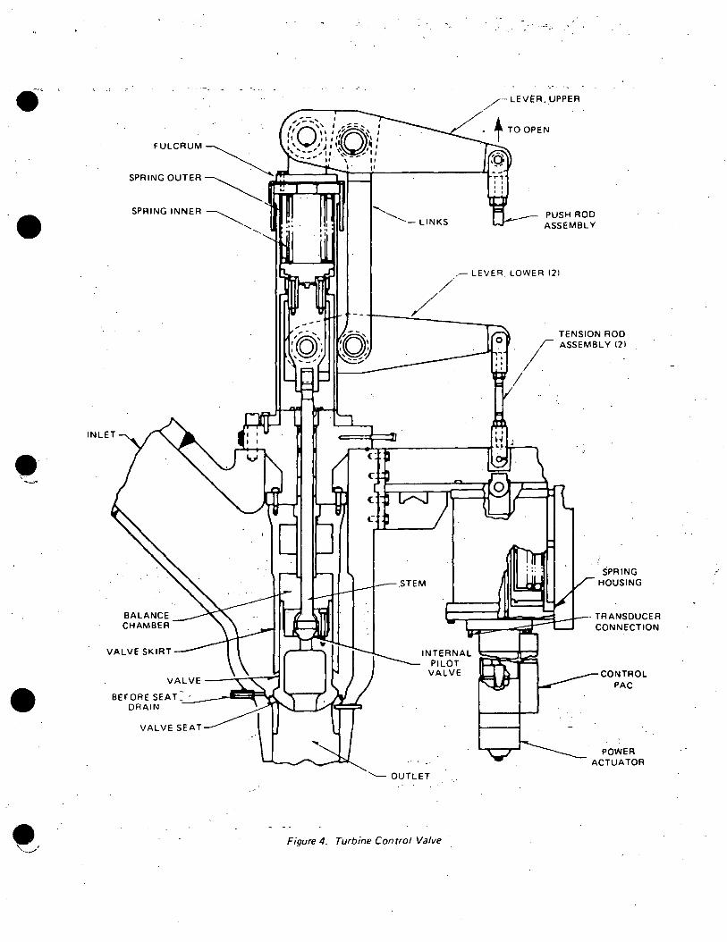
..... 2. Turbine Control Valves {Figure 4)
b. Purpose:
1) To regulate the steam to the turbine within the capability of the reactor to supply steam thereby-;controlling reactor pressure.
2) Also. provides the control for rolling, synchronizing and loading of the machine.
c. Construction:
1)
2)
Valves are welded directly to their respective stop valves.
Each valve is controlled by an operator at the bottom of the valve via the EHC System •
• - 5 -
•
•
E. 2. c. Construction: (Continued)
3) Hydraulically operated open and closed, spring loaded closed.
4) Balanced with internal poppet and balance chamber.
a) When steam is admitted to the steam chest some passes between the valve arid valve skirt to pressurize the balance chamber •
b) During valve, operation the internal pilot (poppet) valve moves less than 20 mils.
(1) Steam is bled past the stem and out the pilot valve seat to the outlet reducing balance chamber pressure.
(2) The valve then opens against less back pressure •
. 3. Combined Intermediate Valves (CIV 1 s) (Figure 5)
a. Quantity is six (6).
b. Purpose:
1) To protect the turbine from overspeeding during a generator· trip or load reject (load dump).
2) The overspeed might occur even if the stop and control valves . close due to flashing of the moisture, in the moisture separators, to steam when the pressure drops within the.turbine, piping and moisture separators due to the vacuum in the.condenser.
:(',. . :1:•. c. Construction··
1) Two valves in one:
a) Intercept valve
b) Stop valve
2) Intercept Valve
a) Balanced sleeve type
·(1) Steam pressure is equalized across.the valve, by holes through the mid-valve plate, balan~ing the valve.
(2) Sleeve means a cylindrical type valve.
- 6 -
c
(
(

•
•
E. 3. c. 2) Intercept Valve (Continued)
·.,•,
b) .Variable position valve that regulates turbine speed during overspeed conditions.
(1) Slow increase in speed.
(a) Remains full open until --105% overspeed •
.(b) Ramps closed and is full closed at 107% overspeed.
(c) Begins to re-open at-102% overspeed, decreasing.
(2) Fast increase in speed.
(a) Begins to ramp closed -102% overspeed.
(b) Begins to re-open at ..... 102% overspeed, decreasing.
c) Normally full open valves.
(1) Ramp open when turbine speed is selected.
(2) Valves 1, 3, 5 open first.
(3) Valves 2, 4, '6 begin to open when 1, 3, 5 are at 50% open.
3) Stop Valves
b)
c)
Unbalanced Disc - Equal pressure across the valve is not required ·as the valve is either full open or full. shut.
Closes on.a turbine trip.
Strictly an emergency valve.
4) Each·valve is controlled by an operator at the bottom of the valve.
5) Hydraulically operated open and closed, spring loaded closed.
•
4. Associated Va-lve Equipment
a. Basket Strainers
1) Installed on Main Stop Valve and Combined Intermediate Valves.
2) Purpose is to prevent injection of foreign material through v~lves to turbine.
3) Usually removed following initial turbine operation.
- 7 -
•
•·
•
E. 4. a. Basket Strainers (Continued)
4) Usually available for re-installation following maintenance.
5) Removed at Dresden.·
b. Valve Linkage
1) On all valves except bypasses.
2) Purpose is to provide valve control as valve parts are differentially expanding and contracting during heatup or cooldown.
5. Turbine Inlet Relief Valves (Low Pressure Relief Valves)
a. Quantity is 6.
b. Purpose:
Protect the turbine low pressure p1p1ng and moisture separators from overpressure which would occur if the CIV 1 s failed in the closed direction with steam still being supplied to the high pressure turbine.
c. Pressure setpoint is 275 psig.
d. Discharge of the valves is piped to the main condenser.
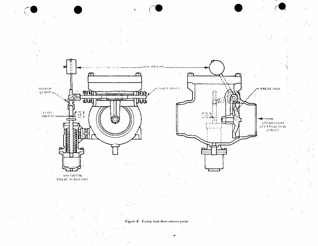
· 6. ·Extraction Non-Return Valves (Figure 6)
a.
b.
Quantity:
One on each extraction s'team line from the LP turbine section to the feedwater heaters.
Purpose:
To protect the turbine from overspeed which might occur when the turbine is tripped and subsequent lowering of pressure in the turbine and heaters (due to vacuum in the condenser) results in flashing of the moisture in the heaters to steam and passage of this steam back into the turbine, throu_gh the blading and· on to the condenser.
- 8 -
(
l., ·.
• ...
•••
•
E. 6. Extraction Non-Return Valves (Figure 6) (Continued)
7.
c. Construction
1) Ordinary check valve
2) Air cylinder on the disc keeps disc lifted up out of the flow path under normal conditions to minimize resistance to steam flow •
3) When turbine trips, air is bled off from the air cylinder allowing the disc to fall partially down into the flow path.
4) If reverse steam flow occurs, the disc slams shut.
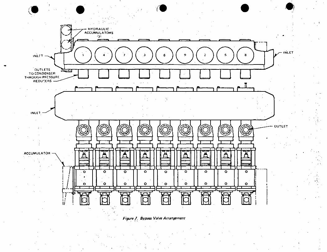
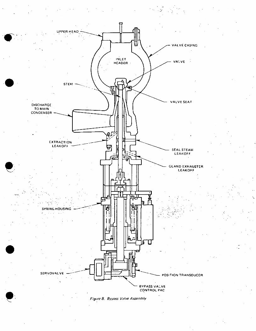
Bypass Valves (Figures 7 and 8)
a.
b.
c •
Quantity is 9. ~ ' ;: • • r
Bypass capacity is 40% by design.
Purpose:
1) To permit establishing a flow of steam to the condenser in preparation for rolling and loading the machine.
2) Also. haridles.·excess steam while unloading the machine or during· a turbine trip. (at· low power). ·
3) Used for passing steam.to the.condenser on a reactor cooldown for decay heat removal.
.~ : '! • • • I
d. Construction
1) Physically located above the turbine throttle. _(Figure 7)
·-' ··:
a) Numbers refer to opening sequence.
b) Discharge is to condenser through pressure reducing · orifices.
c) All bypass valve inlets are welded together forming a header.
~~ . : . ,. : .. . . ' ... :' ~ .. ,
2) Valve Assembly (Figure 8)
a) Valves are operated sequent~ally by EHC oil pressure.
b) Flow path is from inlet header to main condenser.
- 9 -
•
E. COMPONENT DESCRIPTION (Continued)
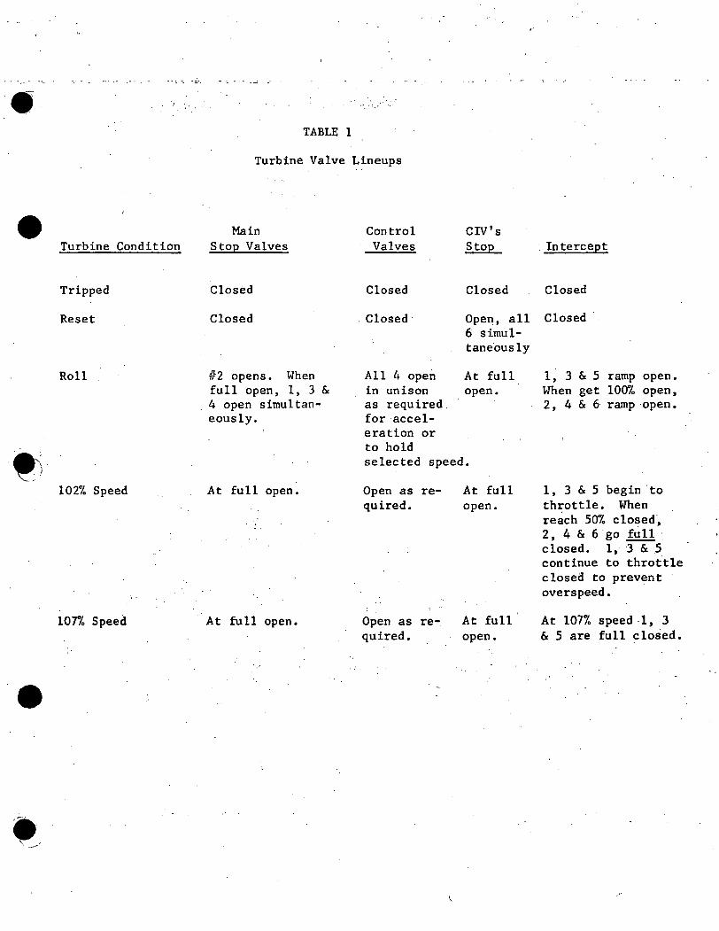
8. Turbine Valve Lineups:
See Table 1.
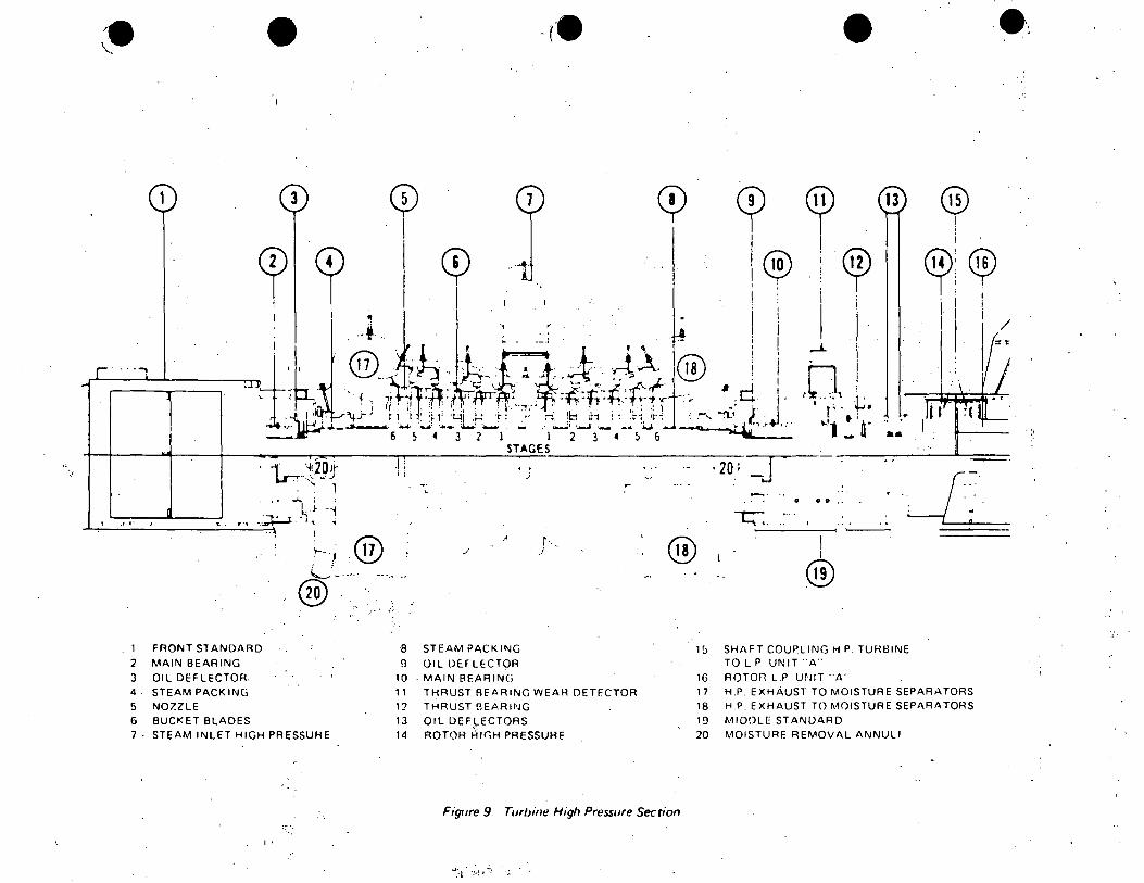
9. High Pressure Turbine Section (Figure 9)
a. Consists of:
1) Front standard ( 1)
2) Six stages (6)
3) Steam inlet (7) (turbine admission bowl)
4) Exhaust to moisture separator (17 & 18}
b • • J' ', •
5) Journal bearings (2 & 10)
6) Thrust bearing (12)
7) Thrust bearing wear detector (11)
8) Coupling to LP (15) ..
Steam is admitted to the turbine admission bowl through four lines at equal circumferential intervals at the center of the turbine. This is called full arc· admission.
c;·- Each end has six stages:'
-d. Each stage has moisture removal by annuli at blade tips. Drains internally to last stage. . ,
e. A ·journal bearing at each end of the HP section provides the only vertical support for the rotor. Normal bearing oil temperature is 150°-160°F.
f. Steam exhausts to the moisture separators •
10. Thrust Bearing
a. Located between journal bearins 2 & 3 between the HP and first LP turbine (A). (Middle standard)
,- 10 -
(
(

•
~-.
•
• '~-·
E. 10. Thrust Bearing (Continued)
b. Purpose:
c.
d.
To prevent any axial motion of the turbine and generator rotor in order to maintain proper clearances between rotating-blades and stationary diaphragms. ·
Axial thrust can occur, for example, due to imbalanced steam extraction .
A thrust bearing wear detector located on the bearing will detect excessive thrust bearing wear (> 0.035") in either direction and will trip the turbine. (Operation covered in G.4.a.)
11. Front Standard
a. Located on the end of the high pressure turbine.
b. Purpose:
· To ho~se various turbine control components such as:
1) Main shaft oil pump
2) Mechanical trip and overspeed trip system
3) EHC system hydraulic control devices
4')-· ,EHC.. permanent magnet generator (PMG)
c. EHC components will be discussed in detail with the EHC System.
_, r .. ::"'- . . · ·' . : ~ .. :
12. Moisture Separator
a.
b.
There are four units.
Purpose:
To remove moisture from the steam before entry to the low pressure turbine .
c. Moisture Removal Section .:•
1) Peerless type moisture removal sections.
2) "Fish hooks" rerri°'~e T!loisture which is piped to the moisture. separator drain tank. (Same principle as for reactor vessel steam drier assembly.)
3) Dry steam passes~to the low pressure turbine.
- 11 -
•
••
E. COMPONENT DESCRJ:PTION (Continued)
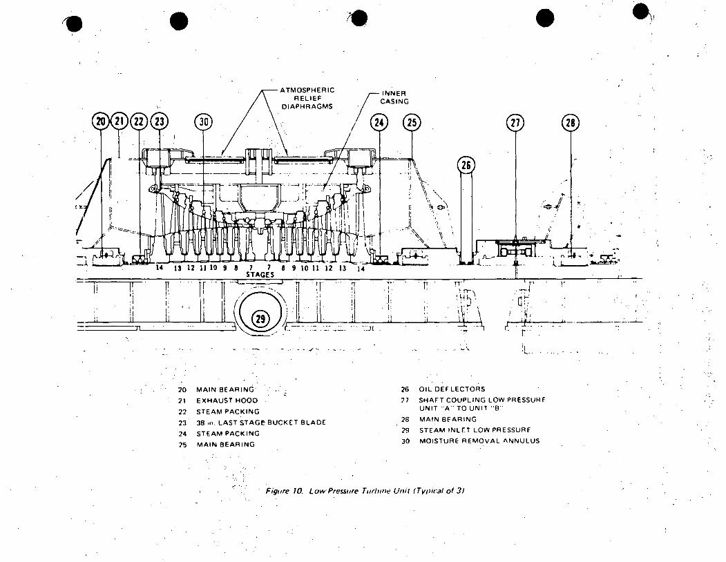
13. Low Pressure Turbine Sections (Figure 10)
.a. Consists of:
1) Journal bearings (20, 28)
2) Eight stages (7 through 14)
3) Atmospheric relief diaphragms
4) Moisture removal annuli (30)
5) Rotor coupling (27)
.b. There are three LP sections.
c. Units are designated A, B, and C starting from the HP end. Each section has eight stages (7 through 14). Last stage blading is 38" ~--
d. Steam is admitted to each LP turbine in two lines through the CIV's.
e. Exhaust is to the individual sections of the main condenser.
f. Inner casing holds the stationary diaphragms.
g. Exhaust Hood:
1) Channels steam to the condenser and provides a means of seiling the rotor shaft.
2) Operates ·at approximately main condenser pressure.
h. Moisture Removal
1)
2)
Each stage has a moisture removal annulus.
The collected moisture drains to the feedwater heaters at designated points~
i. Overpressure Pr·otection
l) Each of the outer casings has two atmospheric relief diaphragms.
2) Purpose: .
To protect the exhaust hood and main condenser from overpressure which, for example, would occur if condenser vacuum.was lost. and steam continued to be sent to the turbine.
- 12 -
(
(
(
•
•
E. 13. i. Overpressure Protection (Continued)
14.
3) Consists of a copper-silver ~lloy sheet.
4) Under normal conditions with the condenser at vacuum, the diaphragm. is dished inward.
5) .On overpressure of 5 psid from within the exhaust hood, the diaphragm is forced outward against a cutting knife thereby opening the relief diaphragm permitting exhaust of up to rated steam flow.
Turning Gear
a. Located between the last LP turbine (C) and the generator.
b. Purpose:
To slowly rotate the reactor at 3 to 5 rpm when machine is shutdown to prevent rotor bowing.
c. Description:
· ... 1) A 60 Hp. AC motor driving a pin(on gear that meshes with the
· tutbine shaft bull.gear.
2) A .7 Hp. piggy-back motor has been mounted on top of the 60 Hp. motor to engage the turning gear.
a) A low torque· motor to prevent turning gear tooth damage.
b) Designed to stall once engaged so large ~otor could be used to :turn Xurbines.
d. Engagement - Disengagement
1) Automatically engages o~ coastdown when machine reaches 0 rpm.
2) Can be manually engaged and then rotated using an air wrench, if nec_essary upon loss of all power .
3) Automatically disengages upon rolling of turbine.
e. Interlocked to prevent operation unless bearing oil header pressure is > _10 psig •
. f. Receives constant lubrication from the bearing oil header at 4 gpm through a restri~ting orifice when header is pressurized.
, - 13 -
•
F. TURBINE AUX ILIA RY SYSTEMS
1. Exhaust Hood Spray System ·. '
a. Purpose
During machine startup or at low loads, steam flow to the last few
stages of the low pressure sections is so low that:
1) Little cooling of the blading is provided by the steam and
2) The blades in the last 1 - 2 sections are actually pumping the steam through the machine (not designed as pumps).
This can result in significant heating of th~ last stage blading and inner casing.
Some cooling must be provided in order to prevent distortion of radial and axial shaft to casing clearances.
Problem is worsened if have significant non-C:ondensab.les in steam.
- 14 -
•
•
.F. 1. Exhaust Hood Spray System (Continued)
b. Brief Description
System consists of:
1) Temperature sensors in the A & C low pressure hoods to detect high temperature conditions. The highest reading detector controls~the automatic spray system .
2) An air operated, temperature controlled automatic water spray valve that controls the flow of demineralized water from the condensate system. Maximum flow is 138 gpm at 100 psig with no load on the turbine.
3) A motor operated bypass valve is provided for bypassing the automatic spray valve in the event of its failure.
CAUTION 0 Do not use bypass valve if exhaust hood temperature is> 135 F.
and turbine-generator is loaded ..
4) Spray nozzles that spray down into the turbine exhaust hood, not the blading or casing, and thus provide indirect cooling of the blading.
5) Instrument air is used for system control.
_ 1) Automatic Temperature Control Valve
a) Begins to open at 120°F.
b) 0 Is full open at 200 F.·
2) · Alarms in Control Room at 175°F.
3) Turbine is tripped at 225°F.
' .. , - 15 -
. Range·
o - 3oo0 :F.
•
•
F. TURBINE AUXILIARY SYSTEMS (Continued) .,
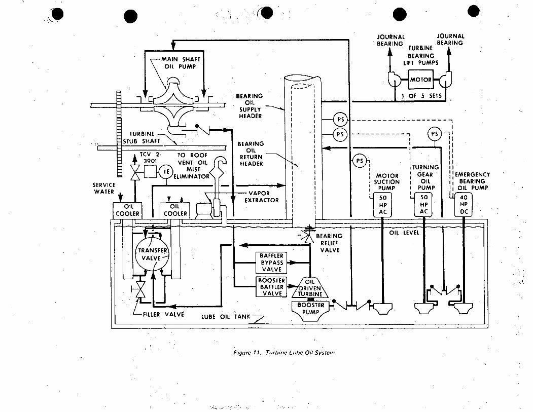
2. Turbine Lube Oil System (Figure 11)
a. Purpose
To supply oil to the following:
1) Turbi~e and generator bearings
2) Thrust bearing and thrust bearing wear detector
3) Overspeed trip reset
4) Oil to test the mechanical overspeed trip device
5) Turning gear
b. Brief Description (Figure 11)
Consists of the foll.owing components:
1) Main lube oil tank
2) Main shaft oil pump (MSOP)
3) Oil driven booster pump
4) Motor suction pump .(MSP)
5) Turning gear oil ·pump (TGOP)
6) Emergency b_earing oil pump (EBOP)
7) Bearing lift pumps
8) Oil coolers
9) Vapor extractor
10) Oil filter and filter pump -
11) Clean and dirty lube oil ·storage tanks
- 16 -
_: •• :: •• 1 ..... :. ',
(
c·
";\
•
•
F. 2. Turbine Lube Oil System (Figure 11) (Continued)
c. Flow Path
1) Prior to Rolling Turbine
a)
b)
Turning gear is engaged and turning.
TGOP is providing lube oil to bearings at-40 psig at the tank.
c) Lift pumps are providing high pressure lffting oil at bottom of bearings.
d) Motor suction pump is running providing- 20 psig at MSOP bearing lubrication.
2) When Turbine is on Line (At speed)
a) MSOP provides oil at- 225 psig ·to booster bypass and baffler · ·><
valves.
b) Booster baffler reduces the oil pressure to the oil driven turbine of the booster pump to ....... 150 psig.
c) Oil exiting the turbine end of the pump goes to the coolers then on to the bearing header at"" 40 psig at the tank.
.d) Service water to the oil coolers is thermocouple controlled to maintain oil temperature at -l00°F. out of t~e cooler.
e) Oil from the booster pump supplies oil to the suction of the MSOP at ...;,,20 psig.
f) ..
Motor suction pump, turning gear oil pump, emergency bearing oil pump and lift pumps are .off.
3) During Turbine Coastdown Following a Turbine Trip
a) MSP will automatically start at 10 psig, at the MSOP_suction, to maintain suction P!essure to the MSOP to prevent damage.
b) TGOP will automatically start at 15 psig bearing oil header pressure to prevent bearing damage •.
- 17 -
.··
•
•
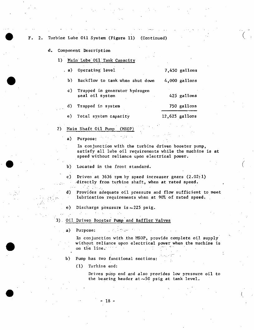
F. 2. Turbine Lube Oil System (Figure 11) (Continued)
In conjunction with the turbine driven booster pump, satisfy all lube oil requirements while the machine is at speed without reliance upon electrical power.
b) Located in the front standard.
c) Driven at 3636 rpm by speed increaser gears (2.02il) .directly from turbine shaft, when at rated speed.
d) Provides adequate oil pressure and flow sufficient to meet . lubrication requirements when at 90% of rated speed.
e) Discharge pressure is -225 psig.
•' ' '
·3). Oil Driven Booster Pump and Baffler Valves
a) Purpose:
In conjunction with .the MSOP, provide complete oil supply without reliance upon electrical power when the machine is on the 1 ine. - - - • . ,, ·
. •, . ~ • I
b) Pump has two functional sections:
(1) Tur~ine end:
Drives pump end and also provides low pressure oil to the bearing header at ....... 50 psig at tank level.
- 18 -
(
(
.(
••• F. 2. d.
•
·' .. _. .. ' '
•
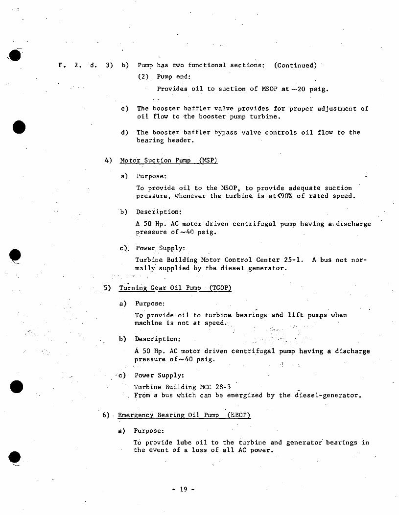
3) b) Pump has two functional sections: (Continued)
'(2) Pump end:
Provides oil to suction of MSOP at -20 psig.
c) The booster baffler valve provides for proper adjustment of oil flow to the booster pump turbine.
d) The booster baffler bypass valve controls oil flow to the bearing header.
4) Motor Suction Pump (MSP)
a) Purpose:
To provide oil to the MSOP, to provide adequate suction pressure, whenever the turbine is at<90% of rated speed.
b) Description:
A 50 Hp.· AC motor driven centrifugal pump having a:· discharge pressure of -40 psig.
c). Power. Supply:
Turbine Building Motor Control Center 25-1. A bus not normally supplied by the diesel generator •
. 5) Tu;_.n ing Gear Oil Pump · (TGOP)
a) Purpose:
b)
~c)
·To provide oil to turbine bearings a~d lift pumps when machine is not at speed.
_,·. ~ · ..
Description:
A 50 Hp. AC motor driven centrifugal pump having a discharge pressure of ..... 40 psig.
Power Supply:
Turbine Building MCC 28-3 From a bus which can be energized by the diesel-generator.
6) Emergency Bearing Oil Pump (EBOP)
a) Purpose:
To provide lube oil to the turbine and generator bearings in the event of a loss of all AC power.
- 19 -
••
•
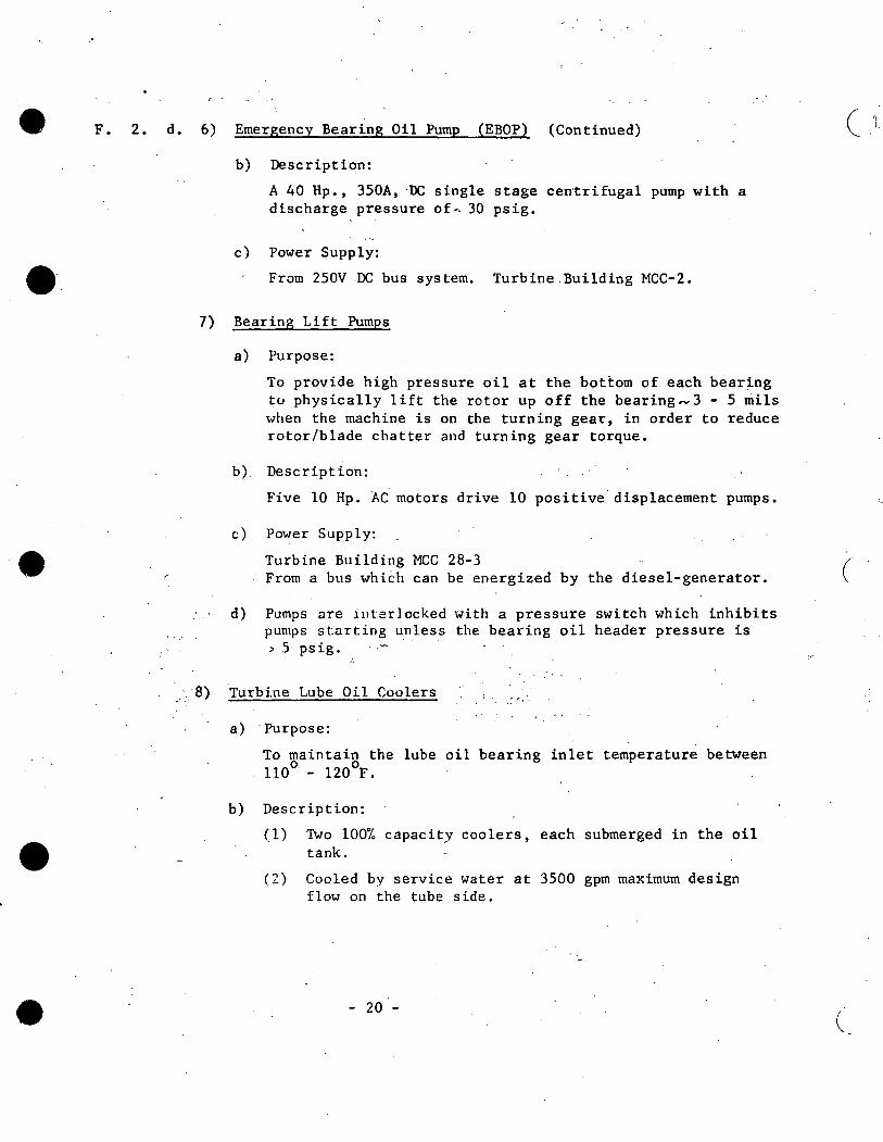
F. 2. d. 6) Emergency Bearing 011 Pump (EBOP) (Continued)
b) Description:
.(>. 40 Hp., 350A, OC single stage cen·trifugal pump with a discharge pressure of-. 30 psig.
c) Power Supply:
From 250V DC bus system. Turbine Building MCC-2.
7) Bearing Lift Pumps
a) Purpose:
To provide high pressure oil at the bottom of each bearing tu physically lift the rotor up off the bearing"' 3 - 5 mils when the machine is on the turning gear, in order to reduce rotor/blade chatter and turning gear torque.
b ). Description:
Five 10 Hp. AC motors drive 10 positive· displacement pumps.
c) Power Supply:
Turbine Building MCC 28-3 From a bus which can be energized by the diesel-generator.
d) Pumps are interlocked with a pressure switch which inhibits pumps starting unless the bearing oil header pressure is > 5 ps ig .
. ·· ·8) Turbine Lube Oil Coolers
a) ·purpose:
To maintain the lube oil bearing inlet temperature between 110° - 120°F.
b) Description:
(1) Two 100% capacity coolers, each submerged in the oil tank.
(2) Cooled by service water at 3500 gpm maximum design flow on the tube side.
- 20 ""
( ')
(
(
•
•
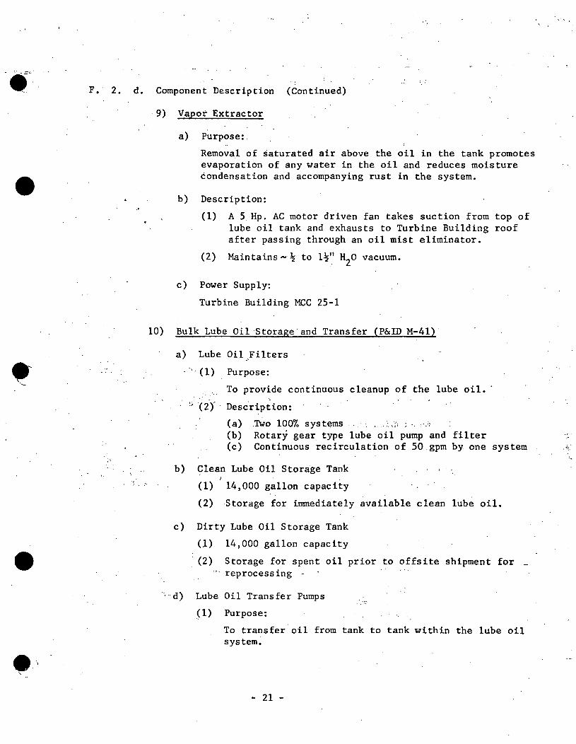
F. · 2. d. Component Description (Continued)
9) Vapor Extractor
a) Purpose:.
Remova.l of saturated air above the oil in the tank promotes evaporation of any water in the oil and reduces moisture condensation and accompanying rust in the system •
b) Description:
(1) A 5 Hp. AC motor driven fan takes suction from top of lube oil tank and exhausts to Turbine Building roof after passing through an oil mist eliminator.
(2) Maintains,,... 32 to l~" H2o vacuum.
c) Power Supply:
Turbine Building MCC 25-1
10) Bulk Lube Oil Storage and Transfer (P&ID M-41)
a) Lube Oil .. Filters
· ·, · (1) Purpose:
. . . ~. To provide continuous cleanup of the lube oil. ·
(2) Description:
(a) .Two 100% systems . . . ... J , · .·1
'•";
(b) Rotary gear type lube oil pump and filter ., (c) Continuous recirculation of 50 .gpm by one system ,,,
b) Clean Lube OU Storage Tank
(1) 14,000 gallon capacity
: ..
(2) Storage for immediately available clean lube oil.
c) Dirty Lube Oil Storage Tank
(1) 14,000 gallon capacity
· (2) Storage for spent oil prior to offsite shipment for _ reprocessing
~-·d) Lube Oil Transfer Pumps
(1) Purpose:
To transfer oil from tank to tank within the lube oil system.
- 21 -
•
•
F. · 2. d. 10) d) Lube Oil Transfer Pumps (Continued)
(2)· Description:
e.
(a) Two 5 Hp. AC motor driven pumps (b) Discharge 75 gpm each
(3) Power Supply:
Turbine Building MCC 25-1 and 26-1
Control Room Ins trumen ta tion
Item Device
1) Bearing Oil Header Pressure Indicator
2) Lube Oil Tank Level Indicator
3) Lube Oil Temperature Indicator
-·
3. Shaft Sealing System
a. Purpose:
..
Range
0 - 100 psig
0 - 8 feet
0 300°F.
To provide sealing for the hiih and low pressure turbine rotors to prevent:
1) Radioactive steam from entering the Turbine Building, and
2) Non-condensables from entering the condenser •
. b. Brief Description:
Steam is provided at~4 psig by means of a pressure control valve to labyrinth type shaft packings on the high pressure and the three low pressure turbine sections.
~ .. ~~ ;~·
c. Components
l) Steam Seal Regulator Assembly
a) Steam seal feed valve, air operated
b) Steam seal bypass feed valve, motor operated
c) Steam seal unloading valve, air operated
d) Steam seal unloading bypass valve, motor operated
- 22 -
·.
("'
('- :·
~
•
•
e ··- ....
•
,,
F. •3. c. 1) Steam Seal Regulator Assembly (Continued)
e) · Relief valve
f) Steam seal header
2) Gland Seal Condensers (2)
. 3) Gland Seal Exhausters (2)
4) Labyrinth-type Turbine Shaft Packing
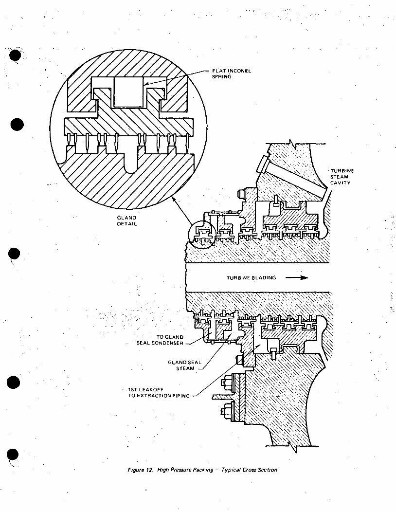
a) Pressure Packing (Figure 12)
(1) Used on HP turbine only. ,·
(2) First leak off is to extraction steam line to the HP feedwater heaters.
(3) Seal steam header at 4 psig.
(a) Supplied by steam seal feed valve during startup and at light loads.
(b) Maintained at high· loads by leak through from HP turbine and action of seal steam unloading valve.
(4) Gland Seal Exhaust Vent
(a) Held at slight vacuum by gland seal exhauster. (b) Removes air in-leakage and any steam leaking from ·
.. gland seal steam header.
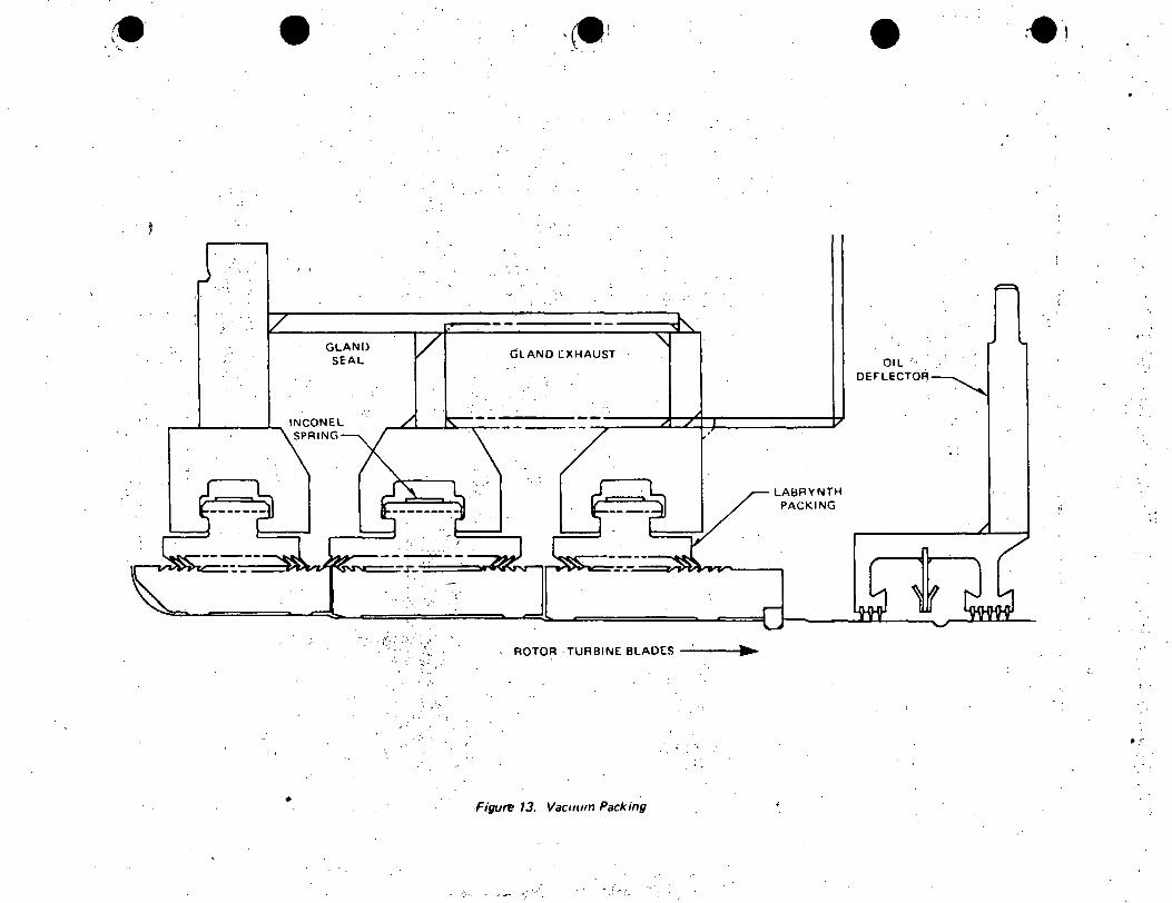
b) Vacuum ~ac~i~g--(Fig.ure l3)
( 1) Used on LP turbine only.- · •• J'::'· .-
(2) Gland seal from seal steam header to reduce air in- . leakage.
. .
(3) Gland exhaust; ~acuum maintained by gland exhauster to remove air in-leakage and seal steam leaking back.
d. Flow Paths (Figure 14)
1) Shutdown to Low Power Operation
a) Steam is supplied to the steam seal feed valve from the turbine throttle.
(1) An air operated pressure control valve.
:_-. · . (2) Reduces pressure to 4 psig downstream of valve . - ·.·.
(3) Valve fails open on loss of signal or air
. - 23 -

•
•
F. 3. d. 1) Shutdown to Low Power Operation (Continued)
... . •..,,
b) A steam seal bypass feed valve is provided for bypassing the steam seal feed valve during low pressure steam supply conditions (< 250 psig).
c)
d)
e)
f)
-Note -
The steam seal feed valve.is designed for rated pressure operation and therefore will not provide adequate seal steam pressure (4 psig) until throttle pressure is7 250 psig •
Sealing steam is applied to the high and low pressure turbine shaft seals. (Figures 12 and 13)
A gland exhauster fan provides a vacuum of 5" H2o to the shaft seal to prevent steam leaking into the Turbine Building.
The exhausted mixture of steam, moisture and air is routed to a gland seal condenser to condense all the steam and return the condensate to the main condenser.
The Bland seal condenser is cooled by the Condensate System.
g) The non-condensables are routed to the Offgas System for processing.
2) High Power Operation
a) .. As reactor power increases, steam pressure at the exhaust of the high pressure turbine increases .
. . .'
b) Steam from.within the turbine now forces its way outward past the inner packing and attempts to increase the steam seal header pressure beyond 4 psig •
. -·~ ...
c) .. Eventually, the steam seal supply pressure control valve completely closes to compensate for this leakage, and the steam seal unloading valve opens as required to maintain 4 psig on the header. (Steam unloading valve fails closed if diaphragm breaks.)
d) Th~ steam seal unloading valve discharges-to the 2A2 and 2A3 low pressure feedwater heater extraction lines (from turbine 12th stage).
e) A steam seal bypass unloading valve is provided. around the steam seal unloading valve in the event it should fail closed.
·~ (
- 24 -
(
(- .
•
• ·9
\ . . /
F. 3. d. 2) High Power Operation (Continued)
f) In this mode of ,operation, steam from the.high pressure shaft seals is the sealing steam for the low pressure turbine section seals.
g) Should the pressure control valves fail, the relief valve will maintain seal system at a safe pressure. Manual control of pressure is then possible with the bypass valves.
e. Control Room Instrumentation
Item
1) Steam Seal Header Pressure
2) Gland Exhauster Suction Pressure
Device
Indicator
Indicator
0 - 10 psig
0 - 30" H 0 2
G. TURBINE PROTECTION AND REACTOR SCRAM INSTRUMENTATION
1. Turbine Trips ,'-•
a. Definition
A trip of all valves closed (except bypass valves) and, ·:·.
~, ,, A trip of the extraction non-return check valves and, ·• ..
A trip of the extraction bypass valves
~.. '
- 25 -
•
•
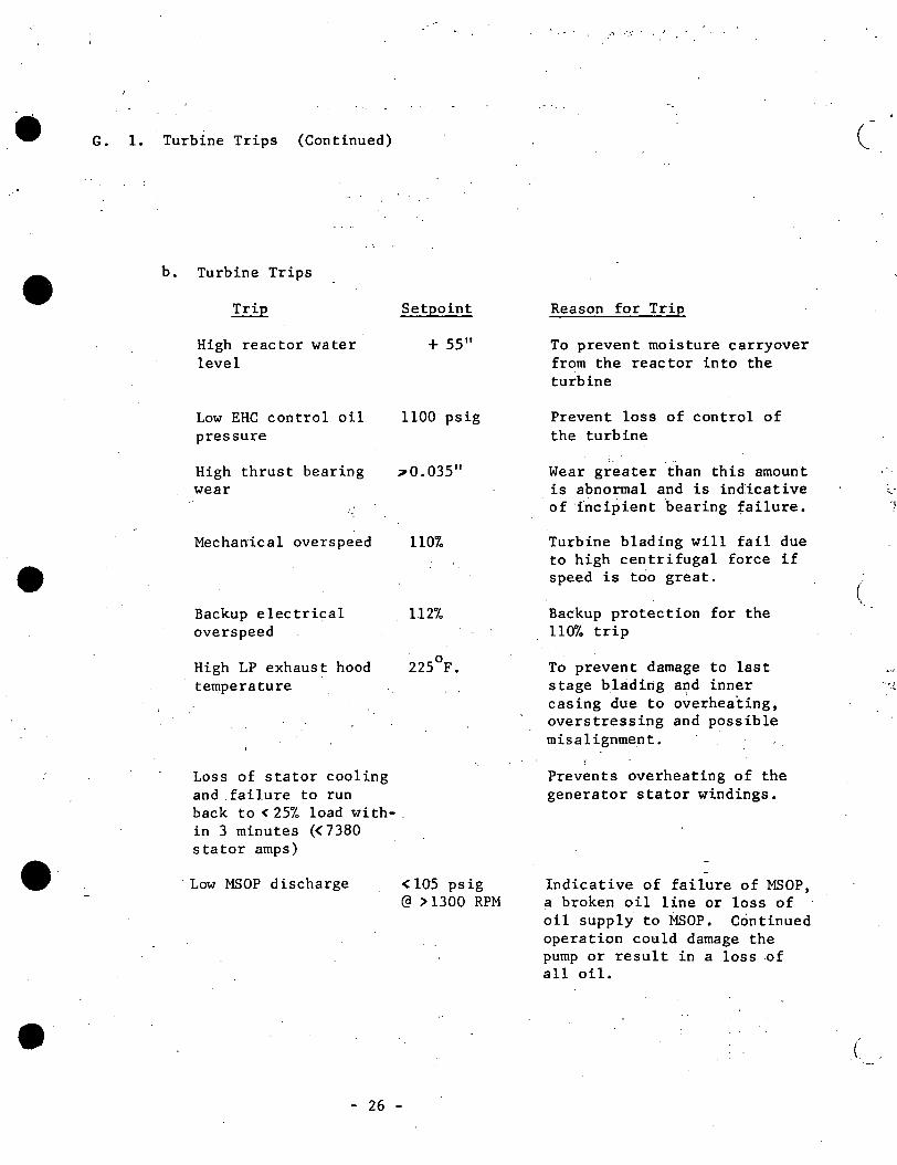
G. 1. Turbine Trips (Continued)
b. Turbine Trips
High reactor water level
Low EHC control oil pressure
High thrust bearing wear
Mechanical overspeed
Backup electrical overs peed
High LP exhaust hood temperature
Loss of stator cooling and failure to run
Setpoint
+ 55"
1100 psig
70.035"
110%
112%
'.225°F.
back to< 25% load with-. in 3 minutes (< 7380 stator amps)
Low MSOP discharge < 105 psig @ :> 1300 RPM
- 26 -
..... ···
Reason for Trip
To prevent moisture carryover from the reactor into the turbine
Prevent loss of control of the turbine
Wear greater than this amount is abnormal and is indicative of ·fncipient bearing failure.
Turbine blading will fail due to high centrifugal force if speed is too great.
Backup protection for the 110% trip
To prevent damage to last stage blading and inner casing due to overheating, overstressing and possible misalignment.
Prevents overheating of the gerierator stator windings.
Indicative of failure of MSOP, a broken oil line or loss of oil supply to MSOP. Continued operation could damage the pump or result in a loss of all oil.
(
(
(
•
9·, " ..
• e. '-......
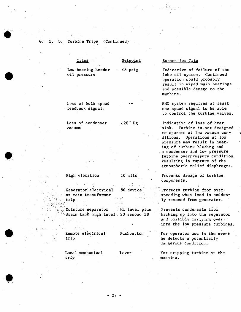
G. 1. b. Turbine Trips (Continued)
Trips
., Low bearing header oil pressure
Loss of both speed feedback signals
Loss of condenser vacuum
Hig.h vibration
Generator electrical ,., ·· · or main trans former
·.~ ··: ::, ,·) .. ·:trip. . . :. -;:-·.-: .... ·::·:/{; ~ - :.·
Setpoint
<8 psig
( 20" Hg
10 mils
86 device.
._ I.~- ~· •• '·
Moisture separator Hi level plus drain tank high level·. 20 second TD
. ~·i
Remot~·el~ctrical trip
Local mechanical trip
Pushbutton
'Lever
- 27 -
. ,. ..
Reason for Trip
Indicative of failure of the lube oil system. Continued operation would probably result in wiped main bearings and possible damage to the machine.
EHC system requires at least one speed signal to be able to control the turbine valves.
Indicative of loss of heat sink. Turbine is.not designed to operate at low vacuum con- ·{ ditions. Operations at low pressure may result in heat-ing of turbine blading and
. a condenser and low pressure turbine overpressure condition resulting in rupture of the atmospheric relief diaphragms.
. :· ";.
Prevents damage of turbine components .
·. Protects turbine from over-speeding when load is suddenly removed from generator •
Prevents condensate from backing up into the separator and possibly carrying over into the low pressure turbines •
For operator use in the event he detects a potentially dangerous condition~
For tripping turbine at the machine.
•
·-
G. TURBINE PROTECTION AND REACTOR.SCRAM INSTRUMENTATION (Continued)
2. Generator - Load Reject
a. Definition:
A greater than 40% mismatch between the main generator electrical output and turbine power •
Comparison is made between stator amps and turbine crossover pressure.
b. Causes of a Load-Reject
1) Manual opening of main generator output circuit breakers. (OCB's) .
2) An "open" in the grid without any lines being grounded.
- Note -
·Any automatic tr:lp of the OCB's will result in a generator: trip rather than a generator load reject.
c. Results of a Load Reject at( 45% Power (measured by 1st stage pressure)
1) Turbine control valve~ are tripped closed by the fast acting solenoids. (Reactor does not scram.)
2) Bypass valves open within their capacity to accept ·steaJll that was going to the turbine.
3) EHC load selector begins running back toward zero load . . .
4) Control valves partially re-open when load-mismatch is <40% to continue carrying hous~ loads ahd machine windage losses.
5) Load selector runback stops when the load-reject; conditi_on is cleared.
6) EHC system will control turbine speed at 1800+ RPM due to the EHC speed control network. (Discussed in.EHC presentation.)
7) No turbine trip occurs.
8) There will be no volts per ,cycle trip of the generator since voltage regulator will. automatically change excitation as required.
9) There will be rio reverse current trip of the generator because the generator is still supplying house· loads. - .
- 28 -
(
( ·--~-
•
, ..
...
• •. ~../
G. 2. c. Results of a Load Reject at(45io Power (measured by 1st stage pressure) (Continued)
10) This condition should not be maintained for any significant period since at low' loads, the exhaust hood temperature will rise and the last stage blades are subject to moisture erosion •
3. Reactor Scrams from the Turbine
a. There are only two scrams originating with the turbine.
1) Main stop valves < 90% full open (bypassed < 45% power as measured by 1st stage pressure)~
2) Generator-load reject. (bypassed< 45io power as measured by 1st stage pressure).
b. Main Stop Valves< 90% Full Open
1) · Scram initiated by valve position limit switGhes.
2) Anticipates the pressure, neutron and heat flux increase caused by the rapid closure of the turbine stop valves.
c. Generator-Load Reject
.t) Scram initiated by limit switches on the fast acting solenoids of the turbine control valves.
·.•·.
2) Anticipates the rapid increase in pressure and neutron flux resulting from fast closure of the turbine control valves due to a load rejec_tjon. ..,_ ., · ;.,._ ·c·
3) Respon•e to load reject
v ..... :; .... ·: ....
a) Turbine control valves are tripped closed by the fast acting solenoids and reactor scrams •.
b) 'All bypass valves open to accept steam that was going to the turbine.
· c) EHC load selector begins running back toward zero load. ~
. d) . T.urbine will shortly run out· of steam n.ecessary to carry the house-loads and windage losses as the reactor decay
-heat decreases.
- 29 -
._,
• )
•
.G. 3. c. 3) Response to load reject (Continued)
:·-.
e) Control valves will eventually end up full open yet the turbine will coast down.
f) Assuming.that the·voitage regulator is still in automatic, the excitation will be automatically increased to hold the rated output voltage .
g) The generator will eventually trip on overexcitation (volts/ cycle trip) to protect the main transformer.
h) The generator trip causes a turbine trip.
4. Control Room Turbine Protection Monitors
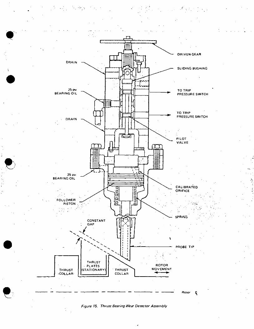
a. Thrust Bearing Wear Detector (Figure 15)
1) Purpose:
a) To protect t~rbine internals by tripping the turbine arr excessive thrust bearing wear or loss of lube oil bearing header pressure.
b) Detect ~radual wear of both thrust bearing plates.
2) Construction:
a) A hydraulically balanced follower piston.
b) A pilot valve is attached to the follower piston to direct oil to and _from pressure switches during normal operation.
!
c) A sliding bushing that directs oil to the pressure switches during tests.
3) Operation:
a) Once initially adjusted the probe tip wil~ maintain a constant distance from the thrust collar.
(1) Oil flows from the bearing header to the top of the follower piston, through the calibrated orifice and out the probe tip to an atmospheric drain.
(2) The follower piston is balanced with half the initial oil pressure on the probe side of the piston.
(3) This pressure is equally developed across the calibrated orifice and the probe tip oil gap.
- 30 -
(
C_.
I
-·
•
•
G. 4. a. 3) Operation: (Continued)
b) Changing thrust would cause the rotor to move changing the gap between the_ probe tip and thrust collar.
(1) ·· This produces a change in oil pressure and unbalances the follower piston •
(2) The follower piston moves up or down, d"ependent upon which direction the shaft moved, to rebalance the oil pressure across t~e piston .
. (3) Movement of the follower piston positions the pilot valve.
(4) ·If movement is excessive, in either direction, oil is ported from one of two redundant pressure switches causing a turbine trip.
4) Test of Thrust Bearing Wear
a) Accomplished by continuously pushing two pushbuttons labeled .:r Turbine End and Generator End on Panel 902-7.
b) This energizes a test motor which drives the driven gear in Figure 15.
c) Allows comparison of thrust collar position to its previous position at the same load.
d) Going to "test" defeats the turbine trip circuits .. but applies the pressure switch contacts to the test'motor
. e)
circuits. .1
11Tk~t 11 moves ·the sliding bushing in. one direction until oil "is ported from one of the pressure switches whose contacts stop the test motor. The position of the bushing is the output indicated.in.the control ·room.
'· f) Output is calibrated in mils both locally and remotely
(control room) and can be compared to previous readings to detect thrust bearing wear.
b. Vibration Recorder and Detector
1) Purpose is to measure the magnitude of the turbine shaft motion in a plane perpendicular to its a.xis.
a) Provides warning of approaching met~! to metal contact and subsequent turbine damage.
b) Trips turbine if vibration is excessive:"> 10 mils.
- 31 -
•
.-
·1 ..
G. 4. b. Vibration Recorder and Detector (Continued)
2) Construction
3)
a) .One detector per bearing; twelve at Dresden. . .. ·
b) · A shaft riding detector mounted vertically to the turbine shaft axis.
(1) A seismically suspended wound coil in a permanent magnet field provides the output signal.
(2) ~utput is calibrated in mils.
Alarms at 5 mils.
4) Turbine trip at 10 mils, can by bypassed at Turbine Supervisory Instrument cabinet in the Auxiliary Electric Room •
c. Eccentricity Recorder and Detector
1) Purpose is to indicate and record the degree of shaft straightness (bow).
2) Shares the same recorder as the Vibration Detector.
3) Construction:
a) An air gap pickup mounted in the front standard on either side of a steel ring attached to the turbine stub shaft
b) Any change in shaft straightness will alternately increase and decrease the air gap between the shaft ring and detectors.
c) The changing air gap increases and decreases the impedance characteristics of the detector which is electronically converted to a signal that is displayed on the recorder.
d) Output js calibrated in mils.
d. Turbine Expansion and Temperature' Recorder
1) Expansion (Figure 16)
a) Purpose is to measure shell and rotor expansion while heating up to warn the operator of possible metal to metal contact within the turbine. - · ·
• '.: ~; '.:.0 .t''."~ :'.._• ,,/ ,: ~-. _, I <•, '
b) During heatup oi.cooldown of the turbine the rotor and HP shell are free to expand and contract. The LP shells, generator stator and thrust bearing are fixed in place.
c) Recorder points
.:,C." ·,_;··.
(1)
(2)
Pt. 1:- Shell Expansion, 0 - 1.0" Upscale on the recorder shows shell expansion toward, the front standard.
Pt. 2: Differential Expansion, 0 - .5" Recorder upscale indicates shell expansion is greater than rotor expansion.
(3) Pt. 3: ·Rotor Expansion, 0 - 2.0" Recorder upscale shows rotor expansion is toward the ·generator.
- 32 -
'
(
., ...
•
•
...... ·" .... · .. !
G. 4. d. 1) Expansion (Figure 16) (Continued)
d) Shell Expansion Detector
(1) Measures expansion of HP shell relative to a fixed point on the floor at the front standard.
(2) As the shell moves a mechanical linkage positions an armature between two opposite facing coils changing their impedance.
(3) The coil outputs are converted electronically to correspond to position; calibrated in inches.
e) Differential Expansion Detector
(1) Purpose is to measure the differential expansion between the HP shell and rotor.
- ' . .,; ~ .. . . : -,: ·,.
H.
: {.
I . ~
TURBINE
(2) Mounted in_the front standard.
(3) Em~loys ·an ~ir gap detecto~ on eithe~ side of a collar on the turbine rotor.
(4) During a plant startup as sealing steam is supplied, the rotor tends to heat and expand faster than the shell and hence recorder indication moves toward zero.
I l
(5) As the turbine is rolled and temperatures equalize, the shell expands and recorder indication moves toward mid-scale.
(6) Normal cold position is mid-scale • .. •; ...
f) Rotor ·Expansion Detector
(1) Similar to differential expansion but measures rotor expansion toward the generator relative to a fixed
. . : point on i:he ·floor.: " ~.~ .J· .':.:;~;-'::-'~_:.; .~~ · '. . '·
(2) The detector is an air gap measuring device using a rotor collar at the generator end.
(3) Output is calibrated to read in -inches.
·-OPERATIONAL SUMMARY
1. Normal Operations:
Will be covered during the control room phase.
- 33 -
•
•
· H. TURBINE OPERATIONAL SUMMARY (Continued)
2. Operating Limitations
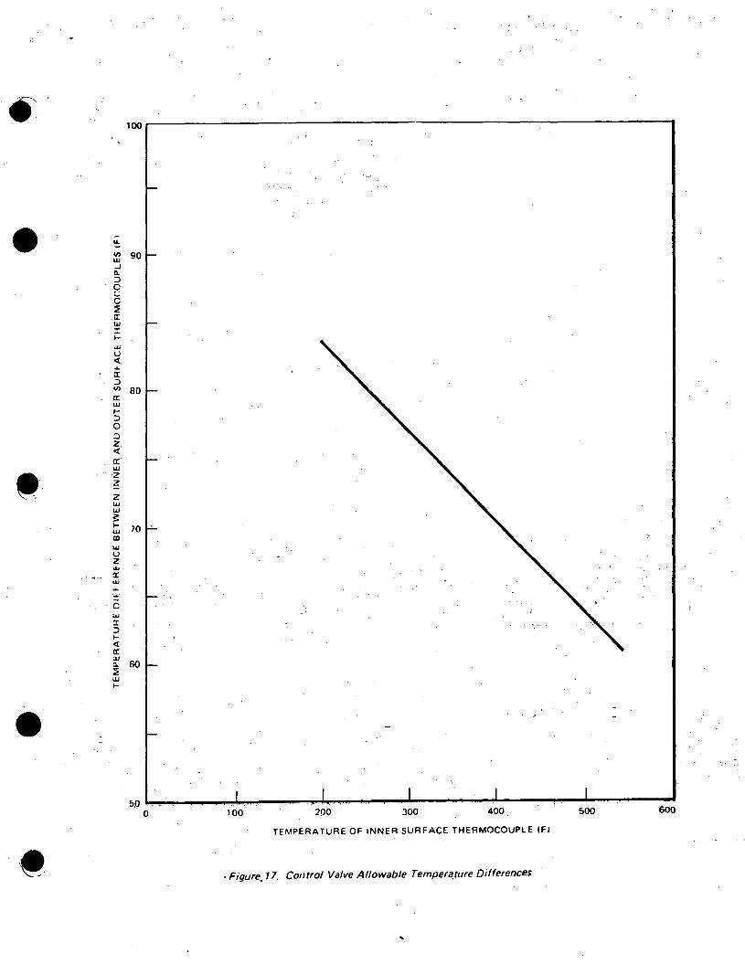
a. Stop and Control Valve Warming Limitations (Figure 17)
1) Procedurally limited to 60°F. nT inside to outside metal temperature for conservatism .
2) Should be essentially at full temperature prior to ro'Iling the turbine to prevent too fast a heatup and possible overstress of the metal due to greatly increased' steam flow during rolling.
b. High Pressure Shell Temperature Differential
Limited to + 150°F. AT inside to outside metal temperatures to prevent excessive thermal stress.
To prevent large 6T's, excessive differential expansion and possible high vibration on a startup of a turbine that is not up to temperature, the following restrictions apply:
Classification HP Turbine Temperature
Range
Acceleration Initial Rate Loading
Loading Rate·
Cold turbine up to 250°F. 60 RPM/min. 3% 0.8%/min.
Warm turbine 250 to 400°F. 90 RPM/min. 5% 1.0%/min.
Hot turbine > 4oo°F. 180 RPM/min. 15% 1.25%/min.
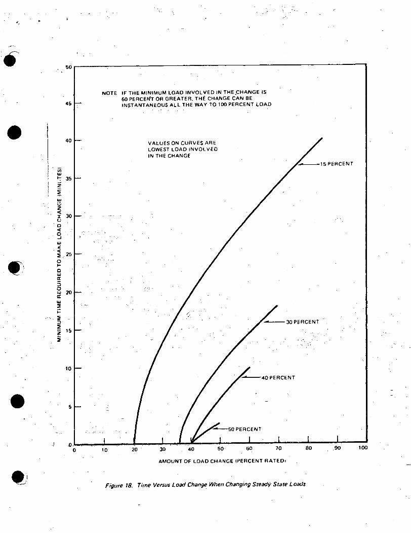
c. Steady-state Load Changes (Figure 18)
1) Stay within 150°F. T limitation at all. times.
2) Figure 18 shows time limitations applied for both pewer increases and decreases. (The curved lines are values for the lowest load involved in the change.)
Example No .. 1:
If the turbine is at 30% power steady state and ~t is desired to increase power to 90%, the power increase must be made over 14 minutes.
Example No., 2:
If the turbine is at 60'~: power, steady state and you want to increase power to 90%, there are no time limitations (as the HP shell is already near maximum t.emperature).
(This is the normal flow control, load following range of ·operations.)
- 3.:. ...
(~. i
.:~
(
c
•
•
•
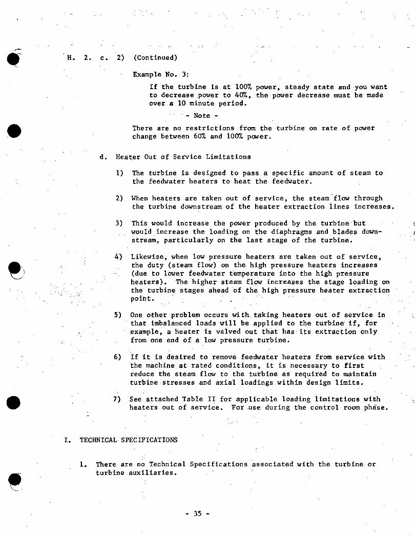
H. 2. c. 2) (Continued)
:_ .... ·
Example No. 3:
If the turbine is at 100% power, steady state and you want to decrease power to 40%, the power decrease must be made over a 10 minute period.
· - Note -
There are no restrictions from the turbine on rate of power change between 60% and 100% power.
d. ·Heater Out of Service Limitations
1) The turbine is designed to pass a specific amount of steam to the feedwater heaters to heat the feedwater.
2) When heaters are taken out of service, the steam.flow through the turbine downstream of the heater extraction lines increases.
3) This would increase the power produced by the turbine· but i;
would increase the loading on the diaphragms and blades down-stream, particularly on the last stage of the turbine.
4) . Likewise, when low pressure heaters are taken out of service., the duty (steam flow) on the high pressure heaters increases (due to lower feedwater temperature into the high pressure heaters). The higher steam flow increases the stage loading on the turbine stages ahead of the high pressure heater extraction poiht. ·
5) One other problem occurs with. taking heaters out of service in that imbalanced loads will be applied to the turbine if, .for example, a heater is valved out that has its extraction only from one end of a low pressure turbine.
6) If it is desired to remove feedwater heaters from service with the machine at rated conditions, it is necessary to first reduce the steam flow to the turbine as required to maintain turbine stresses and axial loadings within design limits •
7) See attached Table II for applicable loading limitations wit-h heaters out of service. For ..use during the control room phase.
I. TECHNICAL SPECIFICATIONS
1. There are no Technical Specifications associated with the turbine or turbine auxiliaries.
- 35 -
.. - . . - . . ... -. . :::~.
·,
• Turbine Condition
Tripped
Reset·
Roll
102% Speed
107% Speed
•
• '· ---·""
TABLE 1
Turbine Valve Lineups
Main Stop Valves
Closed
Closed
#2 opens. When full open, 1, 3 & 4 open simultaneously.
At full open.
At full open.
Control CIV's Valves Stop
Closed Closed
. Closed Open, all 6 simul-taneously
All 4 open At full in unison . open. as required. for ·accel-eration or to hold
.selected speed.
Open as required.
Open as required.
At full open.
At full open •
. Intercept
Closed
Closed
l~ 3 & 5 ramp open. When get 100% open, 2, 4 & 6 ramp ·open.
1, 3 & 5 begin to throttle. When reach 50% closed, 2 , 4 & 6 go fu 11 · closed. l,· 3 & 5 continue to throttle closed to prevent overspeed.
At 107% speed 1, 3 & 5 are full closed.
,.··

•
@)
•
TABLE II
Operation with Feedwater Heaters Removed From Service
The Turbine is designed and built so that heaters may be removed from service without undue loading and overstressing of any part. With heaters out-of service, generator output should be limited to the following percentage of nameplate kw with the various combinations shown to assure safe, reliable and continuous service:
Heaters Out 1 String 2 Strings 3 Strings
D 95% 95% 100%
c 95% 95% 90%
B 85% 85% 85%
c, B & A 85% 80% 75%
B, c, B & A 85% 85% 90%
D & C 90% .. 90% 95%
D, c & B 85% 85% 90%
C .& B 95% 85% 80%
D & B 85% 85% 85%
NOTE
Any simultaneous combinations of the above should be output limited at the lowest value shown.
•
. MOISTURE
SEPARATORS (4)
CONTROL 'VALVES-~--<
MAIN STOP VALVFS--
BELOW SEAT. EQUALIZER----
BYPASS VALVES (9) (DISCHARGES TO CONOEN!i~R NOT SHOWN)
TURBINE THROTTLE ---
I'
MAIN STEAM LINES
-·····'
TO CONDENSER
STEAM JEl AIR EJECTER
SEAL STEAM REGULATOR
• ~
N
I
COMBINED I'---- INTER MEDIA TE
VALVES IC)
LOW PRESSURE RELIEF VALVE
EXCITER
}STEAM CHEST CONDENSER LOW LOAD REHEAT COILS
MAX-RECYCLE REBOILER
18.
·-----14"
LEGEND
e JOURNAL BEARING
• THRUST BEARING
I SHAFT COUPLING
Figure 1. Turbine Steam Flow Diagram ..
"'
•
•
UPPER HEAD~.
VALVE CASING
INLET
VALVE STEM
SPRING HOUSING
I sw~::::::CEA . / .
CONNECTION
Fiq11re 2. Ma111 Sto11 Vrllt,es: Nos. 1. 3. 4
STRAINER
VALVE
VALVE SEAT
BEFORE SEAT DRAIN
~OUTLET
••
•
...
INLET
VALVE CASING
·UPPER
HEAD ----
VALVE STEM-
EQUALIZER-·---
STEM LEAK OFF
SPRING HOUSlf"G
SWITCH BOX - - -
TRANSDUCER ~· / CONNECTION
' /
Figure 3. Main StoJJ Valve No. 2
-- STRAINER
,.,...-- BYPASS VALVE _ .............
...---- CAP
---· -- SLOWDOWN COVER
VALVE
BErORE SEAT /-~DRAIN
-~OUTLET
WA'!'ERSHIELD
- CONTROL PAC
•
• VALVE SKIRT
VALVE~~_.._,,~......,
BErORE SEAT ~----'-l~t:::i~ DRAIN
~-LINKS
/- LEVER .. UPPER
PUSH ROD ASSEMBLY
/ .. -LEVER. LOWER 121
//
'-OUTLET
Figure 4. Turbine Control Valve
TENSION ROD ASSEMBLY 121
SPRING HOUSING
'w-..,-~-l..._"""" .... ~L-..J----TRANSDUCER CONNECTION
CONTROL PAC
POWER ACTUATOR

e \
•
• .e c
LEVER
PUSH ROD ASSEMBLY ..
BALANCE CHAMBER
r •NLET~
STEM LEAKOFF
INTERCEPT SPRING HOUSING J
l:=
POWER ACTUATOR. -INTERCEPT VALVE
:'
TRANSDUCER CONNECTOR
CONTROL PAC
POWER ACTUATOR. STOP VALVE
. , .. : ....
CROSSHEAD
STRAINER
INTERCEPT VALVE
BEFORE SEAT DRAIN
STOP VAi V!= SPRING HOUSING
'\. . CONTROL PAC
' "'--TAANSOUCEA
CONNECTION
Figure 5. Combined.lnter111ediate Valve
~ .
ce
t 1···;111 :;w1 rl·11
• ~. •
·- .... ·-· _________ ())~;~ \-\-'[ l(.itl I ________ ·------1~
/,...- H1Jl.f :;ttnr 1
~~~.t:::::~~~;;;;;:;;~t==:Ll.J~~)/
/\II! l'!ST!.)1\1.
Vl\LVf 1\C:lll1' JOH
Fiy11m 6. F>. trJctiun N1111.ret11m valve
t'r~I ' . 11 fl
11 II .. -.i-!-1-(\ - -~\'\::. I I
I I
I I -- ,1 I
L_'..:".J..+.:: Ir: I
r - .1. .-L - ,~1:::=1 I ' ,_ - -l I
VAlVL l>l:;K
STf.A~J FHl)~.1
I.I' r XTH~r: r111N ~ i I\ l d" ~~
•• ·(e • .. .. ~.
-4'-~--r-- HVORAULIC · ACCUMULA TOHS
000000000' OUTLETS
TO CONDENSER THROUGH PR[!'SURF.
HEDU~ERS
INLET
.; .
ACCUMULATOR~---
I
I :
v T I : I 11
.o •
0
0 0 0 0 0 0 0 0 r-1 0 0 0 ·o 0 0 0 0
Figu~ !: Bypass Valve Arrangement
INLET
- '
..... '' ... --: ..
••
•
DISCHARGE TO MAIN
CONDENSER
STEM--. ..
EXTRACTION LEAKOFF __.o--
. ''·. ·~.
Sl'RING HOUSING ___ _.:.--:- .
SERVOVALVE ----
VAL VE CASING
VA!...VE
~ VALVESEAT
--
SEAL STEAM LEAKOFF
GLAND EXHAUSTER LEAKOFF
-- POSITION TRANSDUCER
BYPASS VALVE CONTROL PAC
Figure 8. Bypass Valve Assembly
" "
• 3
. ...,
1 FRONT ST ANDA RD
2 MAIN BEARING
3 OIL DEFLECTOR. 4. STEAM PACKING
5 NOZZLE 6 BUCKET BLADES 7 . STEAM INLET HIGH PRESSURE
I'
CD I
.I: i j
8 n
j
.• ./
STEAM PACKING
OIL OEFLECTpR
-('9
r.. j .. ®
lS
10 ·MAIN BF.ARIN(! l(j
11 THRUST REARING WEAR OETF.CTOR 17 1'.? THRUST P.EARll•JG 18 13 OIL DEFLECTORS 19 14 ROTOR ~IGH PRESSURE 20
Fig11re 9. T11r1Ji11e High Pressure Section
• 13
~.~ j I ! I I /
... • 0 0
~
I I
@
,.. SHAFT COUl'LING HP. TUR HINE TO LP UNIT ""A"" ROTOn L.P ur·JIT ""A"" H.P. EXHAUST TO MOISTURE SEPARATORS H.P. EXHAUST TO MOISTURE SEPARATORS MIDDLE STANDARD MOISTURE REMOVAL ANNULI
•
I
ii
,. 20
21
22
23
24
'}5
MAIN BEARING'
EXHAUST HOOD
STEAM PACKING
ATMOSPHERIC RELIEF
DIAPHRAGMS
_ ... ..,/' ........ .
38 111. LAST STAGE BUCKET BLADE
STEAM PACKING
MAIN BEARING
i . ' I I
26
'} 7
'}8
29
30
• 27 28
26
'.·.
\ ' \1
,. r. rT· r ·. \ rr\ ,.;;-1 ' ~~ ' ·q~ ':: ~ " ,.
" ~ \ :w: ;. ii ~. •m1i t. .fi_
·~ r· 1--...i.+...._ __ ..J;_ ___ ......._ ___ ~--~
_, !i ......
OIL DEFLECTORS
SHArT COUPLING LOW PRESSURE UNIT .. A .. TO UNIT .. B ..
MAIN BFARING
STEAM INL[T LOW PRESSURF
MOISTURE REMOVAL l\NNULUS
t:: '·' . Figure 10. Low·Press11re T11rhme Unit fTypi1:al of JI
. ,.·
-~-. ·.-..... • MAIN SHAFT Oil PUMP
TO ROOF VENT Oil
MIST ELIMINATOR
··.-'(9
: BEARING OIL
SUPPLY HEADER
BEARING Oil
RETURN HEADER
...--+-+---- VAPOR EXTRACTOR
,-- - .,.,. t---- I I I I I I I I I
. I I I I I I I I I I I I I I I I I
BAFFLER BYPASS,_._....,. VALVE
BOOSTER --~ BAFFLER
VALVE
·' LUBE Oil TANK -
BEARING RELIEF VALVE
Figure 11. T11r/Ji11e Lube Oil System
:. -:.~:. ·~·· • :·.: .. • • '!-
• JOURNAL JOURNAL
. BEARING .BEARING TURBINE BEARING
LIFT PUMPS
MOTOR
OF 5 SETS
-------------------, -------- ----.,
MOTOR SUCTION
PUMP
TURNING GEAR
Oil PUMP
OIL LEVEL
EMERGENCY BEARING
OIL PUMP
a· .. •· .....
•
•
.... -... ·
GLAND DETAIL
· ....
TO GLAND . SEAL CONDENSER
. lST. LEAKOFF TO EXTRACTION PIPING
FLAT 1.NCONEL SPRING
TURBINE BLADING
Figure 12. High Pressure Packing - Typical Cross Section
·TURBINE STEAM
.. ,
\
" '} ·.~
•
I I
GLAND SEAL
,...._......_ ___ .............. INCONEL SPRING
I'
..
.. ·.
-,,,
GLAND l:XHAUST
ROTOR ·TURBINE BLADES ----11 ....
Figurt! 13. Vac1111m Packing
. '. f .~
LABRVNTH PACKING
•
OIL·,. . DEFLECTOR
,,
~ ...
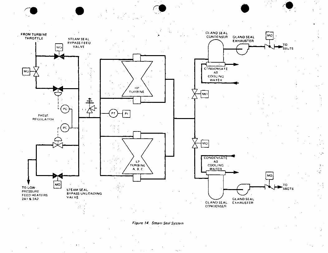
FROM TURBINE THROTTLE
PHES~
RFGlJLA TOH
TO LOW PRESSURE FEED HEATFRS 2A1 & 2A'J
I I I L
r I
• STE:AM SEAL RYPASS FEED
VALVE
SJEAM SEAL BYPASS UNLOADING VAL VF
I'
.•
Figure 14. Steam Seal System
(ii.ANO Sf:AL CONDE Nsrn
cnN!JENSA TE AS
COOLING WATEH
COl\JDENSA TE AS
COOLING WATER
• GtANO SEAL EXHAUSTER
GLAND SEAL GLAND SE.AL EXHAUSlER CONDENSE.fl
. ,,
--· '-
•
•
DRAIN
25 P5• BEARING OIL
DRAIN
25 psi BEARING OIL
. FOLLOWER PISTON ,
. . ~ .
THRUST 1COLLAR·
--:- .
THRUST PLATES
(STATIONARY I
ROTOR MOVEMENT ~ ...
Figure 15. Thrust Bearing Wear Detector Assembly
- ' . - .
DRIVEN GEAR
SLIDING BUSHING
TO TRIP PRESSURE SWITCH
TO TRIP PRESSURE SWITCH
PILOT VALVE
• CALIBRATED ORIFICE
·, J . ·: ('~
PROBE TIP
Rotor ct_
.....

FRONT STANDARD
•
DIFFERENTIAL EXPANSION IPT 71 ··
O ROTOR LONG 5
...
RECORDER UPSCALE INUICATES SHELL EXPANSION GREAHR THAN ROTOR
I SHELL
SHELL EXPANSION IPT. 11
0 to 1.0 ..
UPSCALE ON RECORDER SHOWS SHELL EXPANSION TOWARD FRONT STANDARD
I I
...
THRUST BEARING
SHELL
Figure 16. Turbine Expansion Instrumentation ..
SHELL
•
GEii!ERATOR
.SI
RECORDER UPSCALE SHOWS ROTOR EXPANSION TOWARD GENERATOR }: ·,
jji;' .-.
•
•
~ (/)
w ..J Q.
::> 9 c :?
. a: w :r:: I-..u u <I: . ..L a: ::> (/)
a: w ~ ::> 0 .:i Z. <{
a:· w ·z ~ z w UJ
!: I-UJ ID UJ . u z ..u a: uJ
'"' ·C
UJ :x:
"::> I-<{ a: ilJ Q.
:? w
. I-
90
80
70
60
':' ~. '
50 .......... ----................... _.. .............................. ._ ................ ------------""------------'-----------..a1 600 0 100 200 300 400_ 500
TEMPERATURE OF INNER SURFACE THERMOCOUPLE (fl
- Figure. 17. Con tro/ Valve Allowable Tempera.ture Differences
..
w (;; z <( l: u 0 c( 0 ...J w a!
. <(
~
•> 0 ~
0 w a: ~ 0 w er w ~ I= ~ ~-
~
z ~
• .... :
30
25
20
15
10
5
NOTE IF THE MINIMUM LOAD INVOLVED IN THE.CHANGE IS 60 PERCErJ'T OR GREATER. THE CHANGE CAN BE INSTANTANEOUS ALL THE WAY TO 100 PERCENT LOAD
VALUES ON CURVES ARIO LOWEST LOAD INVOLVED IN THE CHANGE
_·;:.
30 PERCENT
...
-0.i.-_. ................... __ _.. __ _..--...... --""""' ................... -""------------------~----------i--------50· 70 80 .90 100 0 10 20 30 40
AMOUNT OF LOAD CHANGE !PERCENT RATE01
Figure 18. Time Versus Load Change When Chilnging Steady State Loads
••
•
•
... ·)\~' ! ~e.>(
.-
; \,•
A. EHC HYDRAULICS
B. REFERENCES
1. Design Documents
a. Turbine Control Diagram 233R906 b. EHC Seminar material - April, 1973
~. Equipment Manual, Chapter 12
3. Chapter 31, Normal. Operating Procedures
4. Chapter35, Surveillance Procedures '
5. Video Tapes #217, 218, 219, 2311, 231Z
Revision 6 Issued 9/ 1/74
6. Technical Specifications - Section 1.1 and 3.1
7. Turbine Manual GEK 5551, Volume. 1, Section 4
·., ·. ;
C • OBJECTIVES ·
1. Fully understand the purpose of the system and its design basis.
2. ·Learn flow paths and turbine valve operations.
3. ·,_
• _;_'t·:'
Fully understand the function and operation of all components in the· turbine front standard.
4. Significant system instrumentation, trips, and interlocks .
5. Relationships with other systems ,
6. Technical specifications
GENERAL. ELECTRIC
~-·
-."'.: .. -.. :
-2-
D. BRIEF DESCRIPI'ION
1. Function
a. Supplies cool-, clean,. high pressure fluid necessary for. turbine valve operation·.
• 1) Fluid used for control, trip and overspeed f'unctions.
2. Components and Flow Path (Figure 1)
a. Hydraulic power unit reservoir
b. Hydraulic fluid pumps
c. Fluid Jet Supply (FJS)
1) Bypass valves 2) #2. main stop valve internal bypass 3) Control valves 4) Intercept valves #1, 3 and 5
d. Fluid Actuator Supply (FAS)
... e . 1) Combined intermediate stop valves 2) Bypass valves 3) All main stop valves · ...
4) Relay trip valve 5) Front standard trip system
e. Emergency Trip Supply (ETS)
1) Combined intermediate stop valves 2) All main stop valves 3) Relay trip valve
. 4) Extraction dump valve
f. Fluid Actuator Supply Trip Control (FASTC)
• 1) -Control valves 2) -rntercept valves #1, 3 and 5
,. ' '" ..... - -
3) Intercept valves #2, 4 and 6 .. . ....
g. Fluid drains
1) Oil coolers
(\
(.:
e· L.
I,
• E.
• '!>_ .. ·•.•
•
•
.. _ :... .:.. .. · ........ ·
- 3 -
COMPONENT DESCRIPrION
1. Hydraulic Power Unit . (Figure 2)
,_ ·-
a. Hydraulic fluid
1) Synthetic oil Tryaryl Phosphate Ester
a) Brand name FYR-QUEL b) Non-fla.mma.ble c) Maintains viscosity over varying temperature range. d) Water in the fluid will cause hydrolosis giving rise to
acidity.
b. Hydraulic Fluid Pumps .
1) 2 pumps driven by 150 HP AC motors supply 1600 psig pressure.
2) Each pump is 100% capacity. Other pump acts as standby.
a) Standby pump auto starts on low discharge pressure of the running pump ( 1300#) • · · .
3) If discharge pressure exceeds 2000#, relief valves dump back to reservoir.
4) Two full flow 5 micron discharge filters provide the filtering' necessary for reliable operation of the. turbine valves.
c. F\lllers Earth Filt~rs .. . ~ ....
•.l) Removes water and acids to improve system reliability. and extend .the service life o~ hydraulic components.
2) In'continuous service
2. Fluid Jet Supply (FJS)
a. PUrpose:
1) To supply freshly filtered fluid to the servo" valves.
a) Branched off ahead of the other.supplies so that during a transient, the stagnant fluid from the accumulators does not reach the servo valves.
(1) Clearances in the servo valves are small and impurities may clog the strainer or affect valve operation.

·,
•
•
•
'.
- 4 -
E. 2. Fluid Jet Supply (Continued)
.....
b. Servo Valve
1) Function
a) Converts low level input signals from the EHC control logic into high level hydraulic output used to position steam valves.
(1) Servo valves used on bypass valves, control valves, intercept valves and #2 main stop valve.
2) Open-valve Operation (Bypass valve) (Figure 3)
a) FJS fluid enters through a part in the servo valve.
b) It travels through a flexible pipe (jet tube) and impinges on two receiver pipes that are connected to each end of the second stage spool.
c) At··a nulled point (steady. state), approximately one-half the line pressure is developed in each receiver pipe.
d) · Therefore, no differential pressure exists across the spool and it will not move •
e) When a current is supplied to the torque motor armature, ·it develops a torque and the armature rotates through a small angle.
f) ·Assumi~ the armature rotates counter-clockwise the jet .·.tube .would be deflected downwa!"d and pressure would in
crease on the underside of the spool. Conversely, .pressure would decrease.on top of the spool.
g) Thus, a differential pressure exists and would cause the spool to move upward. : · .
h) As the spool moves, a counteracting force is transmitted to the jet tube by the force feedback spring.
i) When the force created by the feedback spring equals the force developed by the torque motor, the jet tube is again symmetrically positioned between the two receiver pipes.
j) No differential pres$ure exists and the spool remains at its new position •
c~·
e L
·;
··-
•
---· •• ~ "--"-·
. I
• . .
- 5 -
E. 2. b. 2) Open-valve operation (Bypass_ valve) (Continued)
..
k) In the example, the upward movement of the spool allows more actuating pressure to be supplied to the steam valve through _port 2 and less through port 1, and the steam valve will open against spring pressure.
1) Feedback to the EHC control console via an LVDT stops the current increase .to the torque motor armature.
m) If the steam valve actuator is single acting, varying pressure from port 2 will vary valve position.
n) On loss of electrical signal, the force feedback spring causes the steam valves to close by ·positioning the jet tube to cause the spool to move downward and the valve to close. 1
o) On loss of FJS fluid, the bias spring causes the steam valve to close by positioning the spool piece to close the valve.
3. Fluid Actuator Supply (FAS) (Figure 2)
...
a. Purpose
l) To provide high pressure actuating fluid to the turbine emergency valves •
. ·'. a) Main stop valves . ·
'r'·
b) . CombineA intermediate stop valves c) Bypass valves
» .
. ._--.. ::f;'2'> ·T·o provide high pres.sure fluid to the turbine front standard . · · '. trip sys_tem. " · , .......... '•
· .. ' ·•· .. · . . . : . . : ' .. ~ ::
. ~ - • .. . • • • ' • .. .; ' "11' '. • •• • : • ' • - • '
a' '-''FAS fluid.'Wi1i=·be·''conve1:'ted~.into.Emergency Trip fluid. .. '. :····.·: ._._· ;. ·.· .. ::;'.:-.· ·. . ..
3) • To provide high:-pressu~e fluid to the relay trip valve for conversion.to Fluid Actuator Supply Trip Control pressure •
b.-.' Main Stop Valve (#1,=.·3, 4) (Figure 4) · . j,.
1) Valves are emergency type - eith~r f'ull open or full closed •
2) Open valve operation
a) When the Emergency Trip Supply (~S) is pressurized and the solenoid operated trip line test valve is de-energized;
(1)
(2)
.Full hydraulic pressure is admitted below the disk dump valve to sea~ it in place. ETS pressure is also transmitted to the shut-off vaJ· to stroke it open. -
•
·=
., ..
- 6 -.. J.
E. 3. b. 2) Open valve operation (Continued)
b) When the shut· off valve opens, it admits full FAS supply pressu:re to the solenoid operated test valve.
c': If the solenoid operated test valve is de-energized (normal state), it will supply full FAS pressure to the stop valve actuator piston.
d) Since the disk dump valve remains closed (larger .surface area underneath), the FAS fluid forces the actuator
_piston to move in an open direction against spring pressure. The valve strokes full open.
e) Some internal leakage past the piston will occur which is passed to the fluid cooler drains via the dump pipe assembly.
·3) Fast Close Valve Operation
a) Rapid closure is accomplished by the following method • . .
(1) The turbine front standard trip system destroys the · ETS pressure. This causes:
(a) The disk dump valve to be released. (b) · The shut off valve to close •
. (2) When the disk dump valve opens, fluid in the ... actuating cylinder is forced downward by the pressure in the cylinder·due to spring tension.
(3) It then flows into a drain annulus where two paths are available.
(a) The greatest portion of the fluid flows through the dump pipe and into the volume vacated by the actuator piston.
(b r The remaining flow is expelled into the drain line.
(4): ,The shut off valve pre'l[ents FAS fluid from draining through the disk dump valve.
"(5) Limit switches sense the position of the main stop valves and send a.scram signal. to the reactor protective system if the valve is < 900/o open.
(6) Accumulators in the FAS supply line are pre-charged to Boo psig with nitrogen. They act as surge volume during transient operation to maintain system pressure.
c .
l ..
••
i .-/.
• A-', ~/
- 7
E. 3. b. 4) . Test Operation
a) The valves are tested in both a slow close and a fast close manner.
b) SlowClosure
(1) Energizing the solenoid operated test valve interrupts .the FAS pressure and slowly bleeds the pressure down through weep holes to the drain system. The steam valve slow closes until it is only 103 open.
c) Fast Closure
. d)
(1) Energizing the solenoid operated trip line test valve effectively destroys ETS pressure to the disk dump valve and shut off valve.
(2) The valve fast closes .the last 103 as described in 3. b. 3) .
The normal test mode causes ·the stop valve to slow close the first 903 of travel and fast close the last 103.
c. .#2 Main Stop Valve (Figure 5)
1) Valve operates basically the same as other 3 stop valves except for internal bypass valve used for steam chest and high
.pressure _turbine shell warming.
2) ETS pressure seals the disk dump valve and the servo valve regulates FAS pressure to the actuator piston.
3) A small movement of the piston to the le~ causes the internal bypass valve to open, passing steam to the steam chest area •.
4) When chest and/or shell warming are complete, the valve will open fully due to the servo valve positioning to supply f'ull
. FAS pressure on the piston actuator •
d. Combined Intermediate Stop Valves
1) Valve operation is identical to the main stop valves.
2) Valves open immediately after turbine is reset.
••
• ·e
·.• ,· ..
- 8 -(
E. 3. e. Bypass Valves -(Figure 2)
.. ~ .. -
. ,-
" _.;.
!. '-.. ••.
''t··-·.
1) . FAS fluid supplies the actuating force.
2) Valve operation is described under servo valve operation.
3) An accumulator check valve arrangement allows ~l minute of bypa.ss valve operation on loss of FAS fluid pressure.
f. Relay Trip Valve
1) FAS fluid converted to Fluid Actuator Supply Trip Control.
g. Front Standard Trip System
1) FAS fluid converted into ETS fluid.for turbine tripping capability.
4. Emergency Trip Supply (ETS)
a. Purpose
1) Supplies high pressure fluid to the disk dump valves through the trip line test valve.
a) Allows emergency valves to be closed rapidly.
b) Destroying ETS pressure by a turbine trip or the trip_. line test valve resl,llts in a fast closure of the valve(s)~-
b~ ,. Fiuid is directed to: ..,- .=-'
•'. ·-· .
.. 1) . . · .. ·
All main ,-s~op valves. -.:·,,. ·.· : .. _,,..:·.:·
.. ·,- ..
2) ,·
Combined intermediate stop valves. .. · ·.
3) R~lay trip valve •
4) Extraction non-return dum~ valve.
c. See Section 3) in FAS portion for fast valve closure operation.
d. See Front Standard Trip System for.generation of trip system fluid.
..
(
•
•·
- 9 -
E. 5. Fluid Actuator Supply Trip Control (FASTC)
... .:..,
a. Purpose
1) Supplies operating and trip fluid to:
a) Control valves. b) Intercept valves (all) .
b. FAS fluid is converted to FASTC if the relay trip valve is positioned properly.
c.
1) Requires ETS pressure to overcome spring force.
a) Interruption of ETS pressure results in interruption of FASTC pressure and a resultant fast closure of the control and intercept valves.
Control Valve
1) Open valve operation (Figure 6)
a) All valves open together to supply steam.
b) When FASTC fluid is pressurized and the solenoid operated fast acting valve is de-energized:
. •'.
(1) Full hydraulic pressure is admitted below the disk dump va.3=-ve to seal it.
c) FASTC pressure is also sent to the servo valve.
d) The servo valve controls pressure to the control valve actuator piston to position the valve against spring force •
. ·.- ·;-' ·.:~'.:_\::~) · The control valve servos are all single acting valves --.; ... ~.···· .· that is they s~pply.pressure to only one side of the
actuator piston. By varying the pressure, the yalve can be positioned anywhere from 0 - 1003 open.
f'
g)
FJS fluid is used to -throttle FASTC fluid and control the pressure to the actuator piston.
Leakage past the actuator piston is bled off through the dump pipe assembly to· the fluid cooler drains.
•
•
- 10 -
E. 5. c. 2) Close Valve Operation
a) Slow closure
(1) Positioning the servo valve to reduce the FASTC pressure to the actuator piston will cause the valve to slow close.
(a) Test operation from operating position to lo% open. (b) EHC control signal
b) Fast closure
(1) Energizing the solenoid operated fast acting valve interrupts the FASTC supply to the disk dump valve.
(a) Energized to fast close valve the last 103 during test operation.
(b) Also energized on a load reject signal •. A limit switch senses the solenoid operated fast acting valve position and if the valve is< 903 open, sends a scram signal to the reactor protective system. This is in anticipation of control valve rapid closure and the resultant, pressure and flux transient.
(2) Interruption of FASTC pressure also causes fast closure.
(a) Turbine trip destroys ETS fluid which interrupts FASTC pressure.
3) Test Operation
a) Valve slow closes until final 10% of travel, then fast closes the rest of the way.
(1) Exercises valve and checks fast closure feature •
d. Intercept Valves #l, 3 and 5
1) Operation is the same as the control valves, except normally full open.
2) Valves begin to throttle closed on turbine overspeed (105%).
(
(
..
•
·-
. ~'
- 11 -
. E. 5. d. 3) · Valves :full closed at 1CY7% speed.
: '~
4) Intercept valves 2, 4 and 6 are slaved to the servo operated 1, 3 and 5 intercept valves •
5) Master-slave. relationship:
a) 4 valve slaved to 1 valve .6 valve slaved to 5 valve 2 valve slaved to 3 valve
b) For example, before the 4 valve can open, the 1 valve must be 9oo/o open. If the 1 valve started to throttle
. closed on turbine overspeed, the 4 valve would not begin to close until the 1 valve reached 503 closed.
c) This arrangement reduces the number of servo valves required and results in increased system reliability •
. d) The master-slave relationship was devised so that a failure of a servo-operated valve in the ~losed direction does not result in the closure of a slave supplying the same low pressure turbine stage as the failed valve. This prevents abnormal turbine loadings since the isolated L.P. stage would act as a drag rather than a prime mover.
e. Intercept Valves 2, 4 and 6 (Figure 7)
l)
2)
3)
Identical in operation to intercept 1, 3 and 5 valves·. except a solenoid operated test valve replaces the servo valve.
. .
If FASTC pressure is present and the solenoid operated fast acting valve is de-energized, the disK dump valve is sealed.
The solenoid operated test yalve stays energized however, ·until the "master" intercept valve is full open.
4) When the "master" valve opens fully, the test valve de-energizes, allowing-FASTC pressure to reach the actuator piston and open the valve against spring pressure.
5) If the "master" intercept. closes to 5oo/o, the test valve is energized and the "slave" intercept will slow close fully •.

•
' ~·
- 12 -
E. 6. Front Standard Trip System
...
a. Purpose
1) Detect undesirable or dangerous operating conditions of the turbine generator and initiate automatic trip action •
a) Converts FAS fluid into ETS fluid.
b) Any trip action destroys ETS pressure.
(1) Trips main and combined intermediate stop valves directly. (2) Trips control and intercept valves through the relay
trip valve. (3) Trips extraction non-return valves through the air
relay dump valve • .. ·.'-
b. Normal Flow Pa.th. (Figure 8) ·. · .. , ·· · ....
...
. :·' :·:.
1) FAS fluid supplied to mechanical trip valve.
2)
3)
5)
Mechanical trip valve output pressure admitted to lockout valve.
Lockout valve output pressure supplied to master trip solenoid valve.
When the.FAS fluid leaves the master trip solenoid valve it is now ETS ·fluid.· ·;
ETS fluid supplies:
a) Disk'dump valve on main 'stop valves.
b} Disk dump valve on combined intermediate stop valves.
c) Relay trip valve.
d) Air.relay dump valve.
c. Overspeed Test Flow Path ·
1) · Lockout valve bypasses the action. of the mechanical trip valve by supplying FAS pressure to the master trip solenoid valve.
2) Mechanical overspeed test can then be conducted without tripping the turbine.
(
- ~- - --!
•
• ~-._)
- 13·-
E. · 6. d. Components
1) Mechanical trip valve ·(Figure 9)
a) Purpose
(1) Interrupts FAS fluid to lockout valve on turbine overspeed conditions •
(2) Unless lockout valve is in test, restilt Will be loss of ETS pressure.
b) Can be tripped 3 ways·:
c)
(1) Mechanical overspeed trip device .: (a) Eccentric (unbalanced) ring
(2) Mechanical trip solenoid (3) Manual mechanical trip handle on front standard
Overspeed test may be performed ·during plant operation without _actual overspeed.
~ ' . . . :· ., ' ·-, • : j --
(1) Lockout valve energized, bypassing mechanical trip valve action.
(2) . Bearing oil 'injected into mechanical overspeed trip device, unbalancing it and causing a trip lever to be actuated. ·
(3) Mechanical linkage positions mechanical trip valve to cut off FAS pressure to the lockout valve'. ·
(4) ·.When test complete, mechanical trip valve reset by bearing oil pressure. ,
(5) · .. Then lockout valve de-energized and system has been · · ' ,, • · returned to normal condition.
2) Lockout Valve (Figure 9) ,. '.•'
a) Purpose
(1) Bypass the action of the mechanical trip valve.and allow overspeed testing •
b) Alternate _source of FAS fluid used to maintain output pressure even when mechanical trip valve trips.
. -c) Lockout Valve will bypass only the mechanical overspeed
test (either actual overspeed or oil trip test).
·-
• •·
• --
I~•
14 -
E.· .6. d. 2) ·Lockout Valve (Figure 9) (Continued)
d) Lockout valve Will de-energize upon actuation of any of the foil owing: (Figure 8)
(1) Manual mechanical trip (at front standard) ( 2) Mechanical trip solenoid
(a) remote trip button (b) Any turbine trip which energizes the master trip
relay. (3) Backup (electrical) overspeed trip
e) ·When the.lockout valve de-energizes, it makes the mechanical trip valve effective again.
3) Master Trip Solenoid Valve (Figure 8) .'
a) Purpose
(1) Converts FAS fluid into ETS fluid ( 2) Provides mechanism for generating most turbine trips
b) Supplies ETS pressure if one or both 24V DC ·solenoids are energized •
. (1)., Normally energized by closed contacts from the master trip relay.
c) De-energizing both solenoids removes the ETS pressure, causing turbine valves to close.
d) A test switch allows testing of one solenoid at a time. ::··
4) Master Trip Relay (Figure 8)
a) Purpose
(1) __ Act.s as a supervisory relay for a number of turbine . trips · (a) See turbine lesson plan for complete list of turbine
. trips.
(
c-·
-
(
---
•
.. . :-
.. ·•·
•
•
-.15 -
E. · .6. d. 4) Master Trip Relay (Figure 8) (Continued)
b) Operation
(1) Normally de-energized (2) A trip signal initiates the following redundant trip
actions: (a). De-energize both pilot solenoids of the master
trip solenoid valve. (b) Energize the mechanical trip solenoid. (c) Locks the master trip relay in electrically (stays
energized) until all trip signals are cleared · and the reset pushbutton is depressed.
(3) Loss of ETS pressure will, through the Emergency Trip pressure switches, lock the master trip relay in an energized condition until the reset button is pushed· and ETS pressure is re-established. (a) The same signal from these pressure switches
5) Trip Button
.will also lock the speed reference in "All Valves Closed" and limit all servo amplifier outputs substantially to zero until ETS pressure is reestablished.
a) Depressing the trip button on the turbine.panel will energize the master trip relay and the mechanical.trip solenoid directly.
6) Reset Button
a) Depressing the reset button will:
(1) Break the lock-in circuits. (2) Reset the vacuum trip circuit (even if vacuum is below
20" Hg). (3) Reset the mechanical trip valve •
Note: The reset _butt an must be held down until -the reset light comes on to assure that the ETS pressure has been re-establisheq •
...
•
•
16 -
E. · .6. d. Components (Continued)
7) Overspeed Trip Test
i ~··
a) Operation of oil test (turbine loaded)
(1) Depress "test" button. (a) Energizes lockout valve, bypassing mechanical
trip valve. (b) "Locked out" light should energize, indicating
lock out valve is in the proper position. (2) Depress "oil trip" button.
(a) Oil will unbalance overspeed device, causing mechanical trip valve to reposition.
(b) "Tripped" light should energize indicating mechanical trip valve in tripped condition.
(3) Depress "reset" button. · (a) Bearing oil used to reset mechanical trip valve
and linkage. (b) "Resetting" light will energize while mechanical
trip valve is repositioning. (c) "Reset" light will energize when mechanical
trip valve is in the proper position. (4) Depress "Normal" button.
(a) Lockout valve will de-energize and reposition. (b) When lockout valve has repositioned the "Normal"
-button· will backlight and the "Lockout" light is off. ·
(5) Test is complete. ,"Normal" and "Reset" lights are energized. Note: ·Depressing turbine trip button anytime during
the test will de-energize the lockout valve and the mechanical trip valve action will be restored.
7. Fluid Cooler Drains
=- a. All fluid drains pass through coolers .before returning to EHC reservoir •
. b. Cooling water is supplied to heat exchanger tubes by Turbine Building Closed Cooling v.ater system.
1) .AnioUn.t of cooling water controlled by temperature of the fluid in the reservoir.
. c-- ~·
\_
(

.• _.-
••
-, __
•
---' ·-'
-- - - - - ---- --- ---F-. · ·Instrumentation
1. Control Room
a. 902-7 Panel
Instrument
EHC Oil Pwnp Amps
EHC Oil Pressure
2. Turbine Building
Instrument
EHC Oil Pressure
Auto Start Test Pressure
EHC Reservoir Oil . Level
EHC Reservoir Oil Temperature
- 17 -
Range
gage 0 - 300 amps
gage 3 -3500 psig
Type Range
gage 0 -3000 psig
gage O -3000 psig
gage -4" to + lb"
gage 0 - 300°F
Significant Interlocks, Trips and Alarms
Item
FASTC Low Oil Pressure
,FAS Low Oil
Setpoint
<900#
Pre-ssure < 1100#
EHC Oil Pump· Low Discharge Pressure (1300#
Function
Causes direct reactor scram if 1st ~tage turbine pressure is > 45%. Anticipates pressure transient caused by imminent control valve closure •
Trips turbine in anticipation of disk dump valves opening. Indirectly (through turbine trip) scrams reactor if 1st stage pressure >45%.
Automat·ically starts standby EHC oil pump.
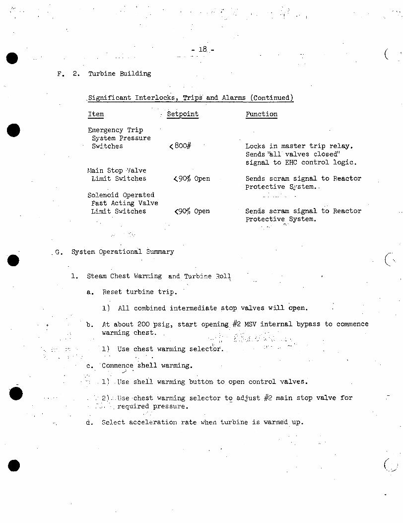
•
•
- 18 .. -
F. 2. Turbine Building
.Significant Interlocks, Trips and Alarms (Continued)
Item : Set point Function
Emergency Trip System Pressure Switches <800# Locks in master trip relay.
Sends 'all valves closed" signal to EHC control logic.
Main Stop :valve Limit Switches <. 90% Open Sends scram signal to Reactor
· protective S~'stem •. Solenoid Operated Fast Acting Valve
''
Limit Switches <903 Open Sends scram signal to Reactor Protective System.
-;-.,-
< :-
. G. System Operational Summary
. ' ' . .
1. Steam Chest Warming and Turbi!!e ~all \
a. Reset turbine trip.
1) All combined intermediate stop valves will open.
b. At about 200 psig, start opening.#2 MSV internal bypass to commence warming chest. . .
", l I :l'." · > · ... ~ , . '· -, ·. . · ~ · 1) Use chest warming select'or ..
c. Conunence shell warming. _/ .
1) .Use shell warming button to open control valves •
2) .. l!se ·chest warming selector to adjust #2 main stop valve for ' ' required pres sure.
d. Select acceleration rate when turbine is warmedup.
(
(·._
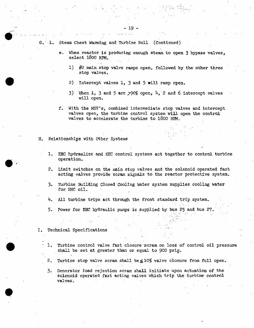
•••
•
9·.
•
•
·.' ·.· .. ·•,•
. - ......... '• ·~
19
G. · .1. Steam Chest Warming and Turbine Roll (Continued)
e. When reactor is producing enough steam to open 3 bypass valves, select 1800 RPM.
1) #2. main stop valve ramps.open, followed by the other three stop valves •
2) ·Intercept valves 1, 3 and 5 will ramp open.
3) vlhen 1, 3 and 5 are /9Cf1/o open, 4, 2 and 6 intercept valves will open.
f. With the MSV's, combined intermediate stop valves and intercept valves open, the turbine control system will open the control valves to accelerate the turbine to 1800 RIM.
H. Relationships with other Systems
1. EHC hydraulics and EHC control systems act together to control turbine operation.
2. Limit switches on the main stop valves and the solenoid operated fast acting valves provide scram signals to the reactor protective system.
3. Turbine Building Closed Cooling water system supplies cooling water for EHC oil.
4. All turbine trips act through the front standard trip system.
5. Power for EHC hydraulic pumps is supplied by bus 25 and bus 27 •
I. Technical Specifications
. ~ .... . ·, ·.\_: ..
'·'-:::.
- 1. Turbine control valve fast closure .. scram on loss of control oil pressure shall be set at greater than or equal to 900 psig.
2. Turbine stop valve scram shall be .s 10% valve closure from full open.
3. Generator load rejection scram shall initiate upon actuation of the . solenoid operated fast acting valves which trip the turbine control valves •
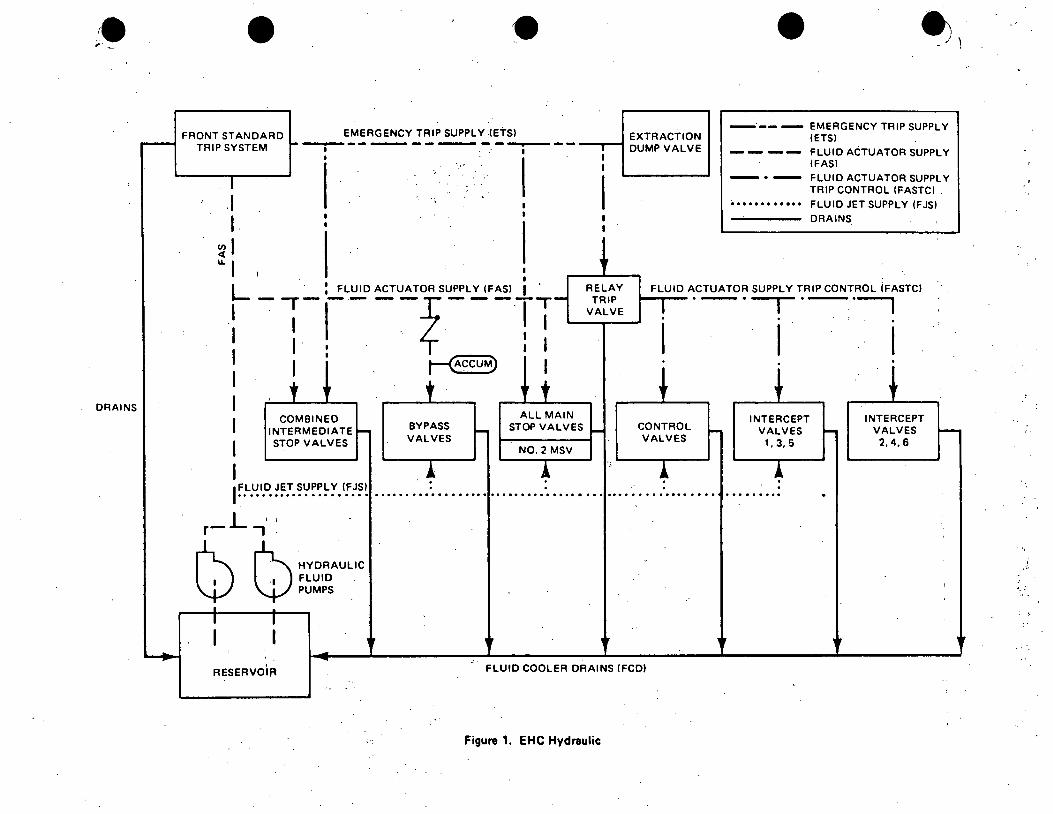
DRAINS
• FRONT STANDARD
TRIP SYSTEM
. I I.
~I u. I
EMERGENCY TRIP SUPPLY .(ETSI --------------
I I I
EXTRACTION ---,-t DUMP VALVE I I
I
• ~ -- - EMERGENCY TRIP SUPPLY
(ETSI
............
FLUID ACTUATOR SUPPLY (FAS)
FLUID ACTUATOR SUPPLY TRIP CONTROL (FASTCl .
FLUID JET SUPPLY (FJSl
DRAINS
L : FLUID ACTUATOR SUPPLY (FAS) I . RELAY TRIP
VALVE
FLUID ACTUATOR SUPPLY TRIP CONTROL iFASTCl
: I I ! I -.--- __ f ____ T
I I I I I 1
1 ~I I I I I
COMBINED INTERMEDIATE STOP VALVES
BYPASS VALVES
ALL MAIN STOP VALVES
NO. 2 MSV
CONTROL VALVES
I . . . . . I ~.L.~I.~ ~~:. ~'!~~~ Y. 'f;'~~ ........ : ................. : . ............ : .... : ....... .
L ,, r- , .
l) l) HYDRAULIC FLUID . PUMPS
RESERVOlR FLUID COOLER DRAINS (FCD)
Figure 1. EHC Hydraulic
·-·---,
INTERCEPT VALVES
1, 3, 5
I
INTERCEPT VALVES 2,4,6
: ..
.
.. ;.:
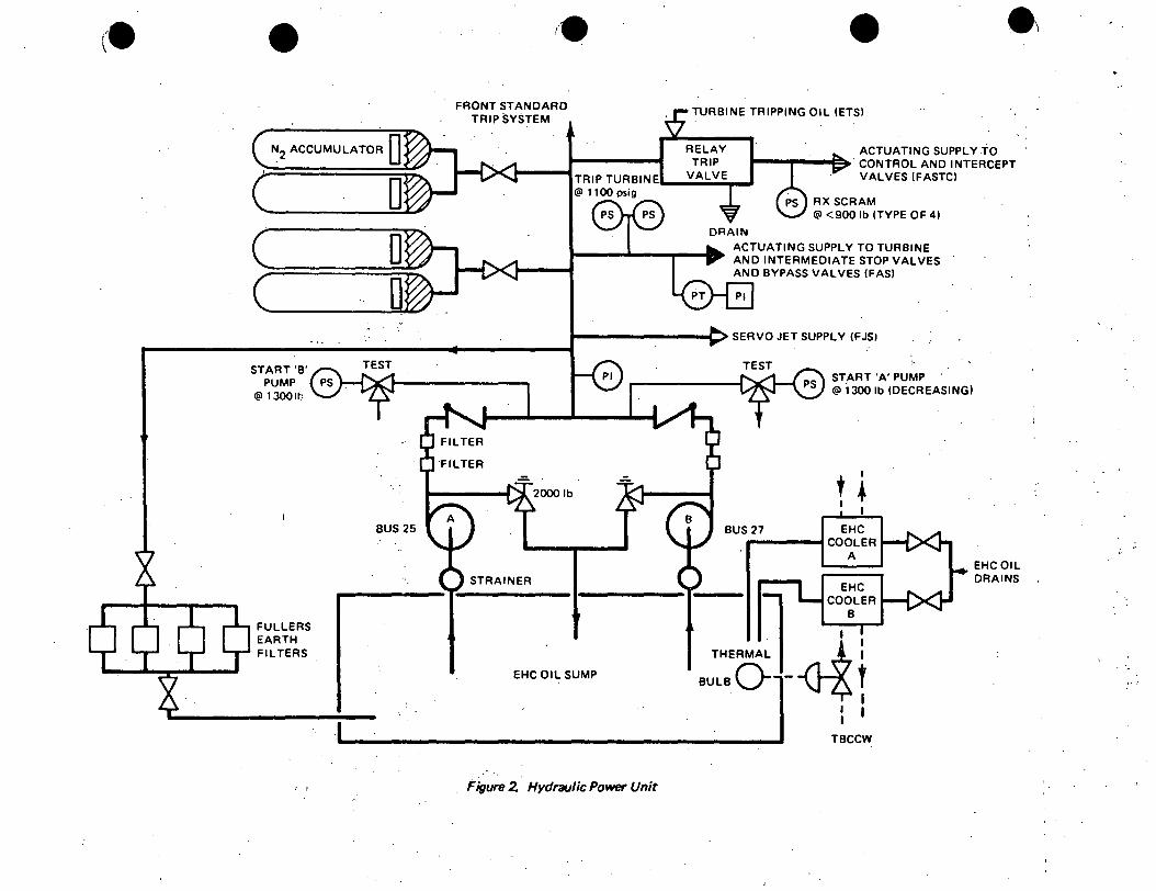
• N2 ACCUMULATOR D
START 'B' PUMP
@ 13001t:.
FULLERS EARTH Fil TEAS
I I
D
BUS 25
I
FRONT STANDARD TRIP SYSTEM
• TURBINE TRIPPING OIL (ETSI
RELAY TRIP
AC TUA TING SUPPLY TO t--...----i~· CONTROL AND INTERCEPT
TRIP TURBIN E._....,v_A_L_V_E-~ @ 1100 psig
DRAIN
VALVES (FASTCI
RX SCRAM @ <900 lb !TYPE OF 41
ACTUATING SUPPLY TO TURBINE AND INTERMEDIATE STOP VALVES AND BYPASS VALVES (FAS)
t---------C::> SERVO JET SUPPLY (FJSJ
START 'A' PUMP @ 1300 lb (DECREASING)
t I
I • I
BUS 27 EHC ____ _.COOLER
A
EHC
EHCOIL DRAINS
EHCOIL SUMP
l COOLER
Figure 2. Hydraulic Power Unit
I I I
TBCCW

• ~STEAM
c:::::::J c==:i 0 0 0 0 0 0
················ ················· ················
:::;111:::11!!i!ii!::1111;1::;1:1N---~'\.
LVDTFOR FEEDBACK
HIGH PRESSURE---. FLUID SUPPLY
1.600 psig
· RECEIVER PIPE
TORQUE MOTOR FIRST STAGE : ARMATURE
JET TUBE
Figure 3. EHC Servova/ve Operation (8ypBS$ Valve)
PILOT SUPPLY
PORT
PORT2
•
EHC CONSOLE · .. t
' I
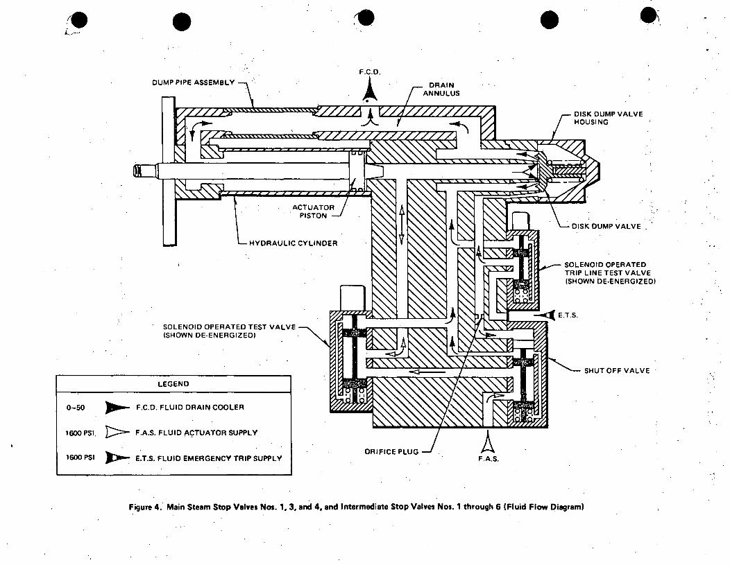
• DUMP PIPE ASSEMBLY
HYDRAULIC CYLINDER
SOLENOID OPERATED TEST VALVE (SHOWN DE-ENERGIZED)
LEGEND
0-50 ,....... F.C.D. FLUID DRAIN COOLER
1600 PSI. }:::::::>- F.A.S. FLUID /'CfTUATOR SUPPL V
1600 PSI ~ E.T.S. FLUID EMERGENCY TRIP SUPPL V
•
ORIFICE PLUG F.A.S.
-. .
DISK DUMP VALVE HOUSING
DISK DUMP VALVE
SOLENOID OPERATED TRIP LINE TEST VALVE· (SHOWN DE-ENERGIZED)
SHUT OFF VALVE ·
Figure 4. Main Steam Stop Valves Nos. 1. 3. and 4, and Intermediate Stop Valves Nos. 1 through 6 (Fluid Flow Diagram)

•• . I.
DUMP PIPE ASSEMBLY .
. :~.
ACTUATOR PISTON
I I HYDRAULIC CYLINDER
SERVO VALVE
LEGEND
·0-50 PSI ......... F.C.D. FLUID DRA_IN COOLER
1600 PSI t:>- . F.A.S. FLUID ACTUATOR SUPPLY
1600 PSI ~ E.T.S. FLUID EMERGENCY TRIP.SUPPLY
1600 PSI ):Ji--- F.J.S. FLUID JET SUPPLY·
F.J.S.
ORIFICE PLyq
Figure 5. M~in Steam Stop Valve No. 2 (Fluid Flow Diagram)
I'
• DISK DUMP VALVE HOUSING
DISK DUMP VALVE
SOLENOID OPERATED TRIP/LINE TEST VALVE (SHOWN DE·ENERGIZEDl
SHUT OFF VALVE
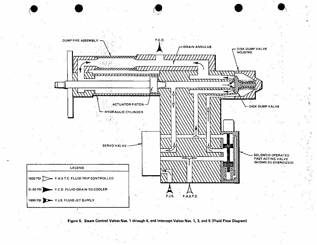
• DUMP PIPE ASSEMBLY .
;'.
ACTUATOR PISTON
HYDRAULIC CYLINDER
SERVO VALVE
LEGEND
1600 PSI }:::::::-- F.A.S.T.C. FLUID TRIP CONTROLLED
0-50 PSI~ F.C.D. FLUID DRAIN TO COOLER
1600 PSI ):::---- F.J.S. FLUID JET·SUPPLY.
___ ,.,
DRAIN ANNULUS
F.J.S. F.A.S.T.C.
• DISK DUMP VALVE HOUSING
DISK DUMP VALVE
SOLENOID OPERATED FAST ACTING VALVE (SHOWN DE-ENERGIZEDI
Figure 6. Steam Control Valves Nos: 1 through 4, and Intercept Valves Nos. 1, 3, and 5 (Fluid Flow Diagram)
.·
': ..
·:.

• DUMP PIPE ASSEMBLY
ACTUATOR PISTON
HYDRAULIC CYLINDER
SOLENOID OPERATED TEST VALVE (SHOWN DE-ENERGIZED). .
I I
LEGEND
0:-50 PSI,...... F.C.D. FLUID !;>RAIN TO COOLER
1600 PSI J:::::=-..: F.A.S.T.C. FLUID TRIP CONTROL
DRAIN ANNULUS
F.A.S.T.C.
Figure 7. Intercept Valves Nos. 2, 4, and 6 (Fluid Flow Diagram)
·~ -·.'
• .·,
DISK DUMP VALVE
DISK DUMP VALVE HOUSING
SOLENOID OPERATED FAST ACTING . VALVE (SHOWN DE-ENERGIZEDI
' .
..
'·'
: ,'
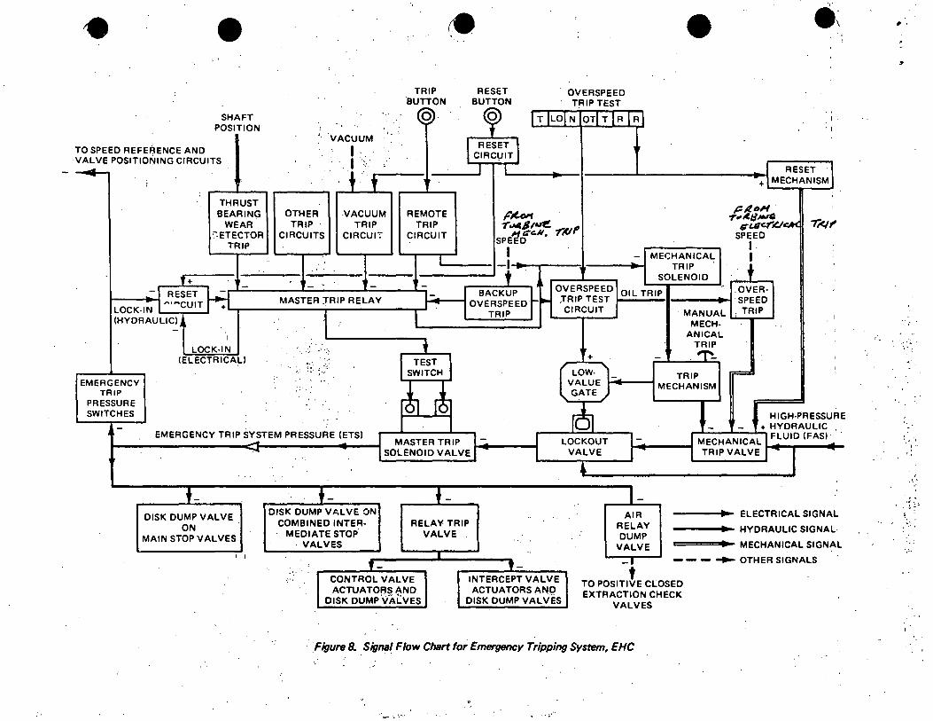
• I'
SHAFT POSITION
TO SPEED REFERENCE AND VALVE POSITIONING CIRCUITS
~
THRUST BEARING
WEAR ':'.HECTOR
TRIP
T+ ~ -_-I RESET
LOCK-IN I "'~CUIT +
(HYDRAULIC), -
I
LOCK-IN (ELECTRICAL)
.. EMERGENCY
TRIP PRESSURE SWITCHES
-
... ..
' ..
VACUUM
' I " . I . ~·. ' + ·,t OTHER VACUUM
TRIP TRIP CIRCUITS CIRCur:·
'.
~ - -MASTER :TRIP RELAY
I ''.
. ·-· : . ·:!: ; ... ,
..
'··
:
TRIP 'BUTTON
0
,.
REMOTE TRIP
CIRCUIT
I
--
I
+ TEST I
SWITCH
r!i r!i
RESET BUTTON
OVERSPEED · TRIP TEST
~ IT LO N OTIT IR IR
l RESET I ·~ CIRCl.JIT
I -
r~ . -r ~$14lf!. -rP I' 1i t:c.11,
SPE D
I --I:.. t .
'
•
MECHANICAL TRIP
SOLENOID , OVERSPEED
, BACKUP r ,TRIP TEST OIL TRIP I OVERSPEED ~ ~
CIRCUIT TRIP MANUAL MECH-
ANICAL TRIP
+ -,,..._
LOW· - . TRIP VALUE MECHANISM GATE
i .
I RESET · 1 - +l MECHANISM
: plf.o" . '
.,.,, A.IJ J#>IG ,;-Ulc.f'l!Jq,<. .,.t<I,
SPEED I I
+ '
.OVER-SPEED
. TRIP I
J
' . ' =
HIGH-PRESSURE
-J_ I ~ +HYDRAULIC EMERGENCY TRIP SYSTEM PRESSURE (ETSI
MASTER TRIP I -:. I LOCKOUT l- I MECHANICAL I FLUID (FAS)~ ~
.,... SOLENOID VALVE I - I VALVE I l TRIP VALVE I I ·~
1
+- +- t- , _ DISK DUMP VALVE ON AIR - ELECTRICAL SIGNAL DISK DUMP VAL VE
ON COMBINED INTER- RELAY. TRIP RELAY HYDRAULIC SIGNAL· MEDIATE STOP VALVE -MAIN STOP VALVES DUMP · VALVES VALVE MECHANICAL SIGNAL ..
I I I - - - ~ OTHER SIGNALS ,_ ,_ _,
J
·t ·'· CONTROL VALVE INTERCEPT VALVE TO POSITIVE CLOSED ACTUATORS AND ACTUATORS Al',IQ EXTRACTION CHECK
DISK DUMP\fALVES DISK DUMP VALVES VALVES
· Figure B. Signal Flow Chart for Emergency Tripping System, EHC
~ .. ;,..
•·
·.:·,'
....
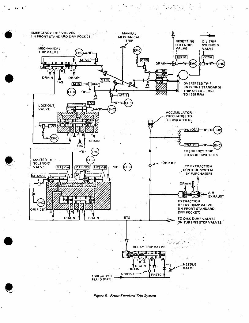
·' .,... .
•
•
EMERGENCY TRIP VALVES - - - . . (IN FRONT STANDARD DRY POCKET)
LOCKOUT VALVE •
MASTER TRIP SOLENOID VALVE
x
:-,
MANUAL MECHANICAL
·TRIP
OVERSPEED TRIP (IN FRONT STANDARD) TRIP SPEED - 1980 TO 1998 RPM
EMERGENCY TRIP PRESSURE SWITCHES
~ORIFICE
ETS
Figure 9. Front Standard Trip System
EXTRACTION RELAY DUMP VALVE (IN FRONT STANDARD DRY POCKET)
TO DISK DUMP VALVES ON TURBINE STOP VALVES
.: " ~
NEEDLE ~VALVE_
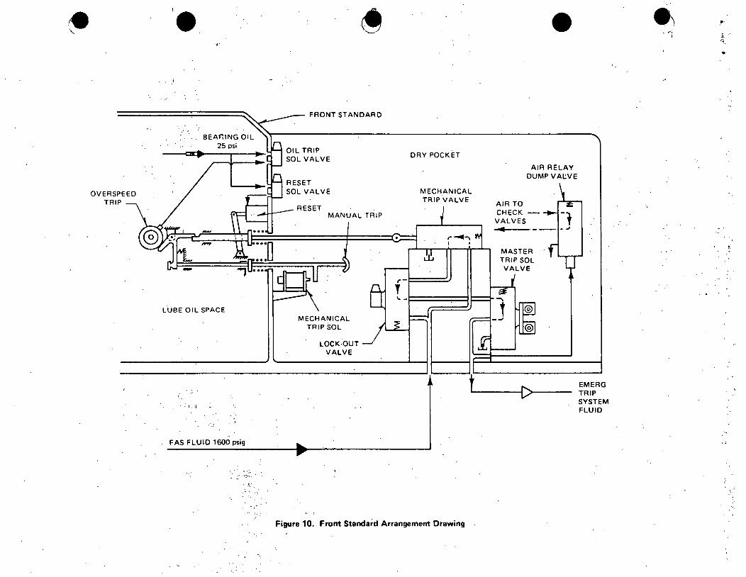
-~·
_:. -··
LUBE OIL SPACE
· · I . ~I
-·:
FAS FLUID 1600 psig
·'!·.:
FRONT STANDARD
MANUAL TRIP
MECHANICAL TRIP SOL
LOCK·OUT VALVE
DRY POCKET
MECHANICAL TRIP VALVE
•
AIR RELAY DUMP VAtVE
AIR TO CHECK VALVES
-4
MASTER TRIP SOL VALVE
'-----~[:>>---
Figure 10. Front Standard Arrangement Drawing
EMERG TRIP SYSTEM FLUID
.•
..
•
••
•
, I ~.: ·;' !:'• ·_ ·~· .. ,:.r
Rev. 1 6/16/75
A. ELECTRO-:-HYDRAULIC CONTROL PRESSURE CONTROL & LOGIC
. B. REFERENCES
1. Design Documents
a. Turbine Control Diagram 233R906
b. BWR Dynamic System Design - Pressure Control Information Document 22A4072, Rev. 0
2. EHC Seminar material - April, 1973
3. Video Tapes #2311 & 2312
4. EHC Manual, Quad Cities
5. ROE 72-13
C. OBJECTIVES·
1. Fully understand the purpose of the control system and its related subsystems.
2. Understand relationship between the main turbine and the Nuclear Steam Supply.System (NSSS)
J. Be able to draw a block diagram of the electrical control system. . · .. · . . ..·~
4. Be able to describe turbine and reactor operation during normal and transient evolutions.
5. Know relationships with other systems •
D. BRIEF DESCRIPTION
1. Effects of changing reactor pressure on a direct cycle BWR
a. Increasing pressure
1) A pressure increase would cause some voids to compress and. collapse, increasing core moderator content •
GENERAL. ELECTRIC
•
-;
•
-2-
2) This increase in moderator results in more thermal neutrons being available for the fission process, thereby increasing reactor ·power.
3) The power increase tends to increase pressure even further, and a snowball effect is produced •
b. Decreasing pressure
1) A pressure decrease would cause some moderator to flash to steam, increasing core void content.
2) This increase in void content results in more neutron ·leakage and a reduction in reactor power.
3) The power reduction tends to decrease pressure even further, etc.
2. Because of the effects in the preceeding discussion,..~ pressure control system was developed in which the reactor power is first changed, followed by a change in turbine power.
a. Increasing reactor power causes:
1) Ari increase in both reactor pressure and turbine throttle pressure.
2) The throttle ~ressure increase requires the turbine control valves to open wider, accomodating the increased steam production.
3) Increasing turbine steam flow increases the generator.output • . , "'·.
b. Reducing reactor power causes: "1 •·
1) A decrease in both reactor pressure and turbine throttle pressure.
2) The throttle pressure decrease requires the turbine control valves to throttle more, decreasing turbine steam flow.
3) Reducing turbine steam flow lowers the generator output.
c. Using this control system, the turbine follows, or is "slaved to"9 the reactor.
3. Pressure Regulation (Fig. 1)
a •. Turbine throttle pressure is compared to a·desired pressure setpoint generating a pressure error signal.
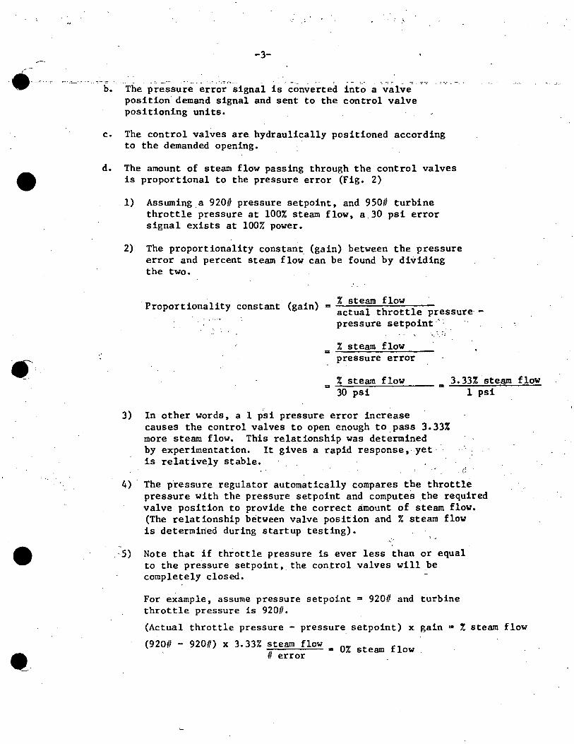
. ·,
•
•
-3-
-· - - • -~ . ·-~ r:-=·-
b. The pressure error signal is converted into a valve position demand signal and sent to the control valve positioning units.
c. The control valves are. hydraulically positioned according to the demanded opening. ·
d. The amount of steam flow passing through the control valves is proportional to the pressure error (Fig. 2)
. 1) Assuming a 9200 pressure setpoint, and 950# turbine throttle pressure at 100% steam flow, a.30 psi error signal exists at 100% power.
-
2) The proportionality constant (gain) between the pressure error and percent steam flow can be found by dividing the two.
% steam flow Proportionality constant (gain)= actual throttle pressure·-
pressure setpoint ·':
% steam flow = ..;.;;....__;;.__;;:""---'----~ pressure error
% steam flow 3.33% steam flow = -"'-"""-"__;;: _ __;;:~--- ... 30 psi 1 psi
.. 3) In other words, a 1 psi pressure error increase
causes the control valves to open enough to.pass 3.33% more steam flow. This relationship was determined by experimentation. It gives a rapid response,. yet· is relatively stable.
4) The pressure regulator automatically compares the throttle pressure with the pressure setpoint and computes the required valve position to provide the correct amount of steam flow. (The relationship between valve position and % steam flow is determined during startup testing).
' --5) Note that if throttle pressure is ever less than or equal
to the pressure setpoint,. the con.trol valves will be completely closed.
For e~ample, assume pressure setpoint = 920# and turbine throttle pressure is 920#.
(Actual throttle pressure - pressure setpoint) x gain m ! steam flow
(920# - 920#) x 3.33% steam flow -------~ • Oi. steam flow II error
----
•
-4-
6) Now assume reactor power is increa~ed and throttle pressure increases to 930#.
(930# - 920#) x 3.33% steam flow # error a 33.31. steam flow _
· ...
7) If power is increased until throttle pressure is 950#, steam flow will be 100%.
(950# - 920#) x 3.330 steam flow= 100~ steam flow II error
e. Also shown for comparison is reactor pressure versus % steam flow. Thi~ relationship is not proportional, primarily due to pressure drops_ across the flow restrictors, MSIV's and steam line piping.
4. Objectives of EHC pressure control system
a. To position turbine control valves, intercept valves, and bypass valves to achieve the desired turbine speed or load -consistent with the nuclear boiler's ability to suppl_y adequate steam.
b. To control and maintain reactor pressure during plant startup, heatup, and cooldown. . '
5. ·In order to meet these objectives, the EHC pressure control system is comprised of these subsystems:
a. Pressure control unit
b. Bypass control unit
c. Load control unit
d. Speed and acceleration control unit
e. Valve flow control unit
E. COMPONENT DESCRIPTION
1. Pressure control unit
a. Purpose
1) To develop control signal representing nuclear boiler steam flow demand.
2) To provide a fast and controlled response to pressure and flow changes and to pressure setpoint changes over the entire operating range.
.. (,
(
··:··
(
..•
•
•
- ""
-5-
1) The process input is turbine throttle pressure measured by redundant pressure transducers. Range ·is from 0-1050 psi.
2) In order to maintain adequate pressure control during turbine stop valve testing, the transducers sense pressure at a pressure averaging manifold •
3) · The two pressure inputs are compared with a desired throttle pressure setpoint producing pressure error signals.
4) The desired throttle pressure setpoint can be varied by operating a motor driven potentiometer using an increase/ decrease pushbutton. Range is 150-1050 psi. Motor speed limits rate of setpoint change to 1 psi/second.
5) The two identical pressure regulator units (A & B) are redundant and both are capable of providing adequate pressure control response.
6) However, to insure positive control by one regulator, a + 10 psi bias is normally pbced on the "B" regulator.
a) This pressure regulator configuration protects against failures of the governing regulator that cause regulator output to decrease substantially.
(1) A regulator failure in this manner would cause
(2')
the control valves to close down, thereby increasing reactor pressure and power.
The backup (''B") regulator will take control during this .failure mode if the "A" output decreases by 10 psi or more.and will limit the severity of the transient.· c>.
' b) 'No backup action is provided if the controlling regulator fails in such a manner as to cause the control valves to open.
' : .. - ~~· .... : . .-~
7) Both regulator outputs are sent to a high valve gate (HVG) where they are auctioneered - the error signal calling for the TQore open control valve position being passed on •.
a) Normally, the regulator which has been biased will have the smallest error signal and it will be stopped at the HVG.

• __ _:_ -- ·-- .o ,,._'
•
•
.-, .
-6-:.:,_. ·- -=- . -~· "": . -- - ~ - . .:-.~: -- ._._ ~
8) The pressure error signal leaving the HVG is converted into a % steam flow demand by a gain unit. (gain = 3.33% steam flow/Oerror).
a) The % steam flow demand will be related to the pressure error as shown in Fig. 2 •
9) The gain unit output is fed to a low value gate (LVG) called the pressure/load gate.
10) The pressure/load gate compares the % steam flow demand from the gain device with several other inputs.
a) The output of the pressure/load gate will be the one calling for the most closed control valve position.
b) The control valve flow control unit (discussed later) receives this demand signal and positions the valves accordingly. ·
11) Other pressure/load gate inputs are shown on Fig. 3.
. ~.
a) Load limit
b)
c)
(1) Variable potentiometer input with range of 0-100%
(2) Restricts the maximum opening ·of the control valves to the value selected by the potentiometer.
(3) Used to protect turbine and/or generator during abnormal operation. · ~
(a) For example, if generator hydrogen pressure was very low and generator output was limited to 70%, the load limit could be set at 70%. This-would "gag" the control valves to a maximum of 70% open, limiting generator load.
Turbine tripped (all 4 stop valves closed)
(1) Negates load limit signar
(2) Applies zero input to pressure/load gate •:.
Other inputs to the pressure/load gate will be discussed in later s·ections.
--(
(
e (
•
•
-7-
·- · .. ·...-;_:::-.. ·. . . ~ :·::- ~- ~~
2. Bypass Control Unit
a. Purpose '.
To generate a bypass valve demand signal in the event the turbine control valves cannot pass the entire nuclear boiler steam prOduction •
b •. Operation (Fig• 4)
1) Output of gain unit sent to a summing junction.
2) This % steam flow demand signal is then compared to the turbine control valve signal equivalent to the % turbine steam flow.
3) If steam flow produced exceeds turbine steam flow, the sunnning junction output represents a bypass v.alve demand.
4) A small close bias is added to insure bypass valves are positively closed .during normal operation. ·
5) A high value gate compares surnriling junction output with an input from a bypass jack.
a) During reactor shutdown and cooldown, it may be desirable to open a bypass valve(s) a small amount for cooling purposes.
6) Frcim the high value gate, the bypass valve steam deman4 passes to a low value gate (LVG) which serves two functions •
. . -··
a) Prevent opening bypass valves when condenser vacuum is low (< 7" Hg). This prevents overpressur izing the
. condenser.
b) Prevent concurrent opening of the bypass and control valves to a value greater than that permitted by the maximum combined flow limiter.
c) The output of the LVG is a bypass valve demand signal and is sent to the bypass valve flow control unit (discussed
•;. · ·later). " ...
7) Maximum Combined Flow Limiter
a) An adjustable potentiometer which places an upper bound on the total turbine and bypass steam flow demand.
/
•
•
-8-- . ·-.-.?-·- ·..;:. _! ::...··
b) By restricting the total steam flow demand, an excessively fast blowdown is prevented in event of a large upscale demand signal failure.
c) During power operation, the limiter i~ set~ 5% above the load limit to keep it from limiting during normal pressure transients at maximum power conditions •
3. Load Control Unit
a. Purpose
To develop a steam flow signal representing the desired load to be placed on the turbine. In addition, a control signal may be sent to the recirc flow control system for automatic load dispatch purposes.
b. Operation
1) The heart of the load control unit is a'-motor-dr.iven potentiometer, which develops the desired load signal.
2) This load signal contr.ols the position of the turbine control valves only if it is less than the pressure control signal into the pressure/load gate.
3) The load s1gnal can be varied by several means:
a) Manually using an increase/decrease button.
b) Manually using the turbin.e governor control switch
c) Remotely, from a central load dispatching station {if quthorized).
4) Several turbine generator conditions require limiting or reducing the turbine load signal.
a) Load rejection runback
-(1) Initiated when a comparison of H.P. turbine
exhaust pressure and generator stator amps indicates a mismatch of)_40%.
(2) Load demand will be reduced (runback) to zero in 45 seconds or until the load rejection conditions clear.
(3) In addition, any load signal present will be . gated to zero when the .load reject occurs.
(
(
-.-~.:~.-·
•
••
-9-
·-...:... ~----~- :;~·= - ·- --
b) Synchronous speed not selected runback
(1) Anytime synchronous speed (1800 RPM) is not selected, the l.oad signal is runback to zero.
(2) Assures that when the turbine is accelerated off the turning gear, the speed and acceleration. control unit governs the turbine speed and not the load control unit.
c) Loss of stator cooling runback
(1) If stator cooling water is lost, the maximum load capability of the generator is 25% of its full load amperage.
(2) The load signal will be runback to 25% load in z2 minutes.
. . ' '·-
(3) 3 minutes after a loss of stator cooling is sensed, the turbine will trip if stator amps are not< 25%.
5) The load signal from the motor driven potentiometer is summed with a steam demand control signal from the speed and acceleration network and sent to the pressure/load gate.
6) This signal would normally be greater than the pressure error steam demand and would not be controlling.
· 7) However, the load demand signal is also sent to a summing •· ., .. junction for comparison with the pressure error steam
deman'd ·and a -10%· bias. · ·'
8) .. · If the Recirc Flow Control System master controller is operating in automatic, the surraning junction output would
·' represent a recirculation flow control signal.
a) For example, assume the gain unit output is 70%, the bias is 10% and· the load demand is 80% •
b) The summing junction "sees" -70%, -10% and +80% for a total signal of z~ro.
c) Therefore,· redrculation flow will not change •
.... . :--.
·,,.
e.
•
•
:..10-
I d) If the operator then demanded an increased load by
raising the load signal to 85%, the sunnning junction .would "see" -70%, -10% and +85% for a total signal of +5%. (Note that the pressure/load gate will not pass the increased load signal) •
. e) This causes. the recirculation pump speed to increase resulting in higher core flow and a power increase.
f) Increasing power and steam production causes reactor pressure to begin to increase, generating a larger pressure error.
g) As the pressure error increases, the gain unit output calls for more turbine steam flow and the control valves open wider.
h) The gain unit output will increase to 75%, returning the summing junction to a nulled condition (-75%, -10%, +85%).
i) The control valves now are passing 75% steam flow and generator output has increased to 75%. The recirc pump speed increase will be terminated.
. j) Note that the load did not change immediately since the reactor power and pressure had to be increased first.
9) .. Recause of the inherent lag in steam flow response during recirculation flow. changes, a faster initial response was devised utilizing a part of the stored energy capacity in the vessel. ...
10) ... •'. """I . .. .
This response can be achieved by temporarily ·decreasing (increasing) the pressure regulator setpoint upon sensing a fast increase (decrease) in load demand.
11) A decreased pressure setpoint would cause an opening signal .to the turbine control valves that allows an innnediate temporary increase in steam flow and turbine output.
12) Decreasing the pressure setpoint initially results in a reactor pressure transient that causes the neutron flux to decrease, but the increasing recirculation flow soon overcomes this and causes power to increase.
13) The gain and limit device provides the pressure setpoint change and also limits the rate and magnitud~ of the adjustment to prevent excessive reactor power excursions.
(
. . (··,
(
. ·,
. II/I/ii( .
·---:. ~
•
I • I·
l j I
I I
e '-._,.;_
...... ...
-11-. . .-.
- ---~":"·.:_~-- ... _. :~.:""' .-~~-- -n:;· -~..:. .-..=....
4. Speed and Acceleration Control Unit
a. Purpose
To develop steam.demand signals for control and intercept valves to control turbine speed and acceleration rate •
b. Operation - Rolling the Turbine (Fig. 6)
1)
2)
3)
·' ,
The process input is turbine speed as measured by two independent magnetic pickups from a 160 toothed wheel located on the turbine shaft.
The pulse rate from the pickup is converted into a voltage signal represe.n_ting turbine speed. Two independent channels provide redundancy. (For simplicity of explanation, only the "A" speed control network will be discussed.)
The speed signal is processed by two separate devices ~ a SJ>eed control section and an acceleration control section.
4) A summing junction in the speed control section compares the turbine speed with a desired speed as selected by the operator. Speed selections include:
".
5)
6)
7)
a) All valves closed
· b) 100 RPH
c)·· 500 RPM
d) 1500 RPM . . _; .. -.•
· f) Overspee.d test ·'
I '. • ,, -~-- '.· ~·.:,.. :"~· : ~j i·:) .• ·- .:: ..
., .. ~. -;, :i.!T :. ~ ~:-·.;. .:.··:-: t,-":; ·
. ( ,.,•
• ~-.:·.: ._l ·• f, '·~ . I ·.
If "All Valves Closed" is selected, the summing junction output will be strongly negative, demanding full closure
·of all. intercept ·and control valves. >
If the turbine is at rest and any speed is selected, a large speed error signal is generated and sent to the Low Value
·.Gate (LVG).
This.signal would demand full open control valves unless overridden by the acceleration section.
-·--.
•
•
... -12-
: · .. •·::.-:-::""' -~-. : . .:-=
8) The acceleration section is comprised of 3 devices: .
9)
·:a) Differentiating unit
b)'·. Summing junction ·~··. ·. \... . . . '·
-Pi).,.· .integrating unit , .• . = .
'· Differentiating the turbine speed produces an acceleration signal.
10) The summing junction compares the actual turbine acceleration to a desired acceleration which is selected by the operator.
a) Slow (60 RPM/min)
b) Medium (90 RPM/min) . '
c) Fast (180 RPM/min)
Note that one of 3 acceleration rates is always selected.
11) The acceleration error produced .at the SUIIUiling junction is integrated which converts it into a speed error signal.
·Both the acceleration' control section and the speed control section outputs are speed error signals •
12)
. ,.
If the turbine is at rest, and ''All Valves Closed" is ·selected, the acceleration control sect'ion will be stro~gly positive, demanding full open control v~l~e~~ .. The. speed control section', via the· LVG, will keep the valves: closed.
13) At the instant a.speed is selected, the two sections switch outputs. The speed control section now demands full open control valves. The acceleration control section, due to a capacitive feedback (not shown on drawing) demands full closed control valves.
14) As the capacitor discharges, feedback is reduced and the acceleration control signal increases until it is· demanding enough steam flow to accelerate the turbine at the desired rate.
,f
a) A 3. 6 RPM speed error is required for 180 RPM/min. acceleration rate. This would produce~ 4% steam flow demand to the control valves.
( <.
•
•
-13-
15) ·When turbine speed reaches :::::.1796 RPM, the speed control section output has decreased enough to take control via the LVG.
· 16) A speed er£or signal of 61. 8 RPM is necessary to keep the turbine. rolling at near rated speed. This speed error corresponds to~ 2.0% steam flow demand •
17) The preceding discussion is graphically illustrated in Figure 7.
a) At time T0 , the following conditions exist.
(1) Integrator output is in positive saturation (+5 volts) due to zero turbine acceleration
.and an.acceleration demand (assume 180 RPM/min)
(2) "All Valves Closed" is selected so speed control summing junction output. is. in negative saturation·,
•. (-5 volts).
(3) Turbine RPM is zero.
h) At time Tl, the operator· selects 1800 RPM. This causes . 3 actions:
. (1) The large speed error Just· introduced causes the speed control sumniing junction output to go to
· : - ·:·positive saturation (+ 5V) . • ".i. .. .,,..J.'" '. , .· .... ;, .
. (2) . A capacitive feedback to the integrator input ·drives :it into negative satura.tion (-5V).
(3) As the capacitor discharges, the.existing acceleration error begins to increase integrator output. . .
c) At time T2, integrator output becomes positive. This causes:
(1) ·Control valves to begin opening
(2) Turbine to accelerate
d) The integrator output will increase until turbine acceleration rate matches the desired acceleration rate. When the integrator input is zero, the output will be constat'lt at .some. small positive value. The magnitude depends on the rate selected.
•
•
.. ··
_"':":_.::• .
. e)
-14-
The.turbine accelerates at the selected rate until the speed error becomes small (;.;'4 RPM).
f) At time T3, the small speed error has caused the summing junction'output to decrease until it becomes the controlling signal. As this occurs:
(1) Turbine acceleration decreases causing the acceleration integrator to go to positive saturation (+5 volts).
g) The summing junction output will now be a small positive value, enough to maintain~ 2i. steam flow to keep the turbine rolling at ~1798 RPM •
. h) To bring the unit up to 1800 RPM for synchronizing, the operator would use the turbine governor switch to increase steam flow demand.
i) When 1800 RPH is reached, the speed error is zero.
j) If any speed other than 1800 RPM were desired', the acceleration process would be very similar to that already described. The only changes would be:
(1) The resultant turbine speed would be the selected speed~
. (2) ,·
The time required to reach the desired speed would be less. (Assuming 180 RPM acceleration rate) ·
. . . A selected acceleration rate of < 180 RPM/min. would be reflected in 3 ways:
(1) Acceleration integrator output amplitude will be ·1ess during the acceleration period.
(2) The slope of the RPM vs.Time curve will be different
(3) The time required to reach selected RPM will be lonKer • .-
c. ··Intercept Valve Regulation (Fig. 6)
l) Intercept v_alves normally full open or full closed, but can be throttled to prevent excessive turbine overspeed.
( .
( '•
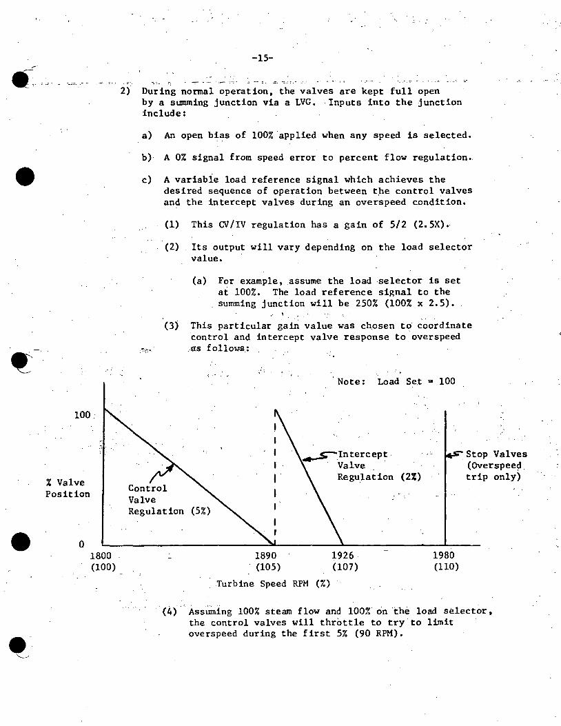
•
100.
,, ,+,
% Valve Position
• 0 1800 (100)
-15-
2) During normal operation, the valves are kept full open by a summing junction via a LVG. Inputs into the junction include:
a) An open bia.s of 100% applied when any speed is selected.
b) A 0% signal from speed error to percent flow regulation •.
c) A variabie load reference signal which achieves the desired sequence of operation between tpe control valves and the intercept valves during an overspeed condition.
(1) This CV /IV regulation has a gain of 5/2 (2. 5X).
(2) Its output will vary depending on the load selector value.
(a) For example, .assume the load selector is set at 100%. The load reference signal to the summing junction will be 250% (100% x 2.5).
,. I .... ,
(3) This particular gain value was chosen to· coordinate control and intercept valve response to overspeed
,~·:·:· AI.S fallows.:
I •
Valve
Note: Load Se.t .. 100
~Intercept. · Valve .
Regulation (2%)
_Stop Valves (Overspee~ trip only)
Regulation (5%)
1890 (105)
Turbine Speed RPM (%)
1926. (107)
1980 (110)
· <4> , .Ass.i.llning ioor. steam flow and 100% on "the load selector, the control valves will throttle to try to limit ovetspeed during the first 5% (90 RPM).
•
••
t~ . ..
-16-
·--· ._~:- - -- _.:.,._
(5) .· Due to large quantities of steam contained in the turbine and separators, turbine speed may.increase even after control valves have closed.
(6) The intercept valves will throttle closed from 105% ~ 107% turbine speed.
(7) If turbine speed increased to 110%, a turbine trip would occur, closing the main stop valves and the combined intermediate stop valves as well as the control and intercept valves.
(8) If the control and intercepts were not sequenced in this manner, they would both try to control overspeed by throttling the same steam and turbine speed oscillations could develop.
d. Chest Warming Feature
1) Steam chest warming is accomplished by opening the f.12 main stop valve (MSV),internal bypass. This can be done while. the turbine is on the jack. .
2) Selecting any turbine speed causes the #2 MSV to open fully.
3) Limit switches at 90% open on #2 MSV cause MSV's 1, 3 arid 4 to open fully.
5. Valve Flo~ Control Units
a. Purpose _,/·
Converts steam flow request ·into .valve position. request. Also provides feedback mechanism for nulling out demand signal. . , . .c.
b. Control Valve Positioning Units (Fig. 8)
1) Control valve demand is sent to a function generator which converts the steam flow request into a~ electrical control valve stem lift ·demand. This signal w~ll be the inverse. of actual valve steam flow characteristics.
2) The stem lift demand is compared to actual stem lift by a summing junction.
3) · Any error existing is sent to a servo amplifier and servo valve for.conversion into a hydraulic control signal.
. ~ . .~ .
... ·
(
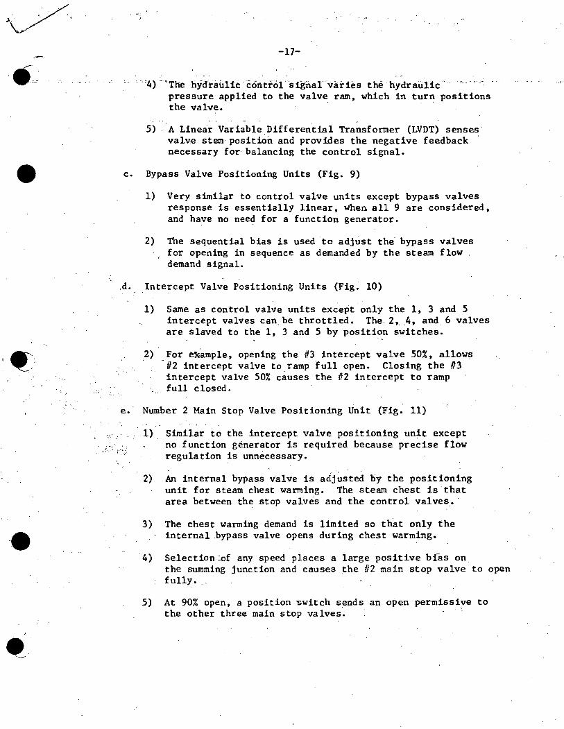
•
••
.... : .. '
-17-
.·.o4r··~Tne liydrauliC "c:ontf-01··sig-11ar·varies the.hydraulic· pressure applied to the valve ram, which in turn positions the valve.
5) A Linear Variable Differential Transformer (LVDT) senses valve stem position and provides the negative feedback necessary for balancing the control signal •
c. Bypass Valve Positioning Units (Fig. 9)
1) Very similar to control valve units except bypass valves response is essentially linear, when all 9 are considered, and have no need for a function generator.
2) The sequential bias is used to adjust the bypass valves for opening in sequence as demanded by the steam flow demand signal.
.d. Intercept Valve Positioning Units (Fig. 10)
1) Same as control valve units except only the 1, 3 and 5 intercept valves can. be throttled. The 2, _4, and. 6 valves are slaved to the 1, 3 and 5 by position switches.
,2) For ek.ample, opening the 113 intercept valve 50%, allows 112 intercept valve to. ramp full open. Closing the 113 intercept valve 50% causes the 112 intercept to ramp full closed.
. . . e. Number 2 Main Stop Valve Positioning Unit (Fig. 11)
· .. ........ . ..... I •• ~· ~ •,
1) Similar to the intercept valve positioning unit except no function generator is required because precise flow regulation is unn.ecessary.
2) An internal bypass valve is acij~sted by the positioning unit for steam chest warming. The steam chest is that area between the stop valves and the control valves. ·
3) The chest warming demand is limited so that only the internal .bypass valve opens during chest warming •
4) Selection~of any speed places a large positive b~as on the summing junction and causes the #2 main stop valve to open fully.
5) At 90% open, a position switch sends an open permissive to the other three main stop valves. · '

•
.e
•
; :- ..
-18-
f. Shell Warming Function
1)
2)
"3)
4)
Tile high pressure turbine shell may also be warmed up prior to operation by a shell warming feature.
Selection of "shell warming" accomplishes the following actions:
a) Essentially inserts a 100 RPM speed demand in the speed control section.
b) Removes the pressure gain unit as an input to the pressure/load gate.
c) Applies a zero bias to the intercept valve LVG.
· These actions allow the control valves to be opened. Adjustment of the load limit potentiometer will limit the magnitude of the opening. . .. ,.
·' . .
Steam flow is controlled by positioning of the 112 main st'op valve.
5) Biasing the intercept valves closed prevents steam from reaching the L. P. turbine and possibly rolling t}te turbine •.
: . ~
F ~· SYSTEM OPERATIONAL SUMMARY
1. EHC controi system operation is best understood using exampl,es·. :-The following discussion will 'begin at low temperature and pressure and ,terminate at 100% power·wi-th recirculation flow in automatic •
.. . . j ~· .. {/.i" •' -~-:~.-
Reactor critical kt the point. of adding heat, mode ·switch ·'ln startup ~ •' "• • •,J • • ! ', • .... :.f ,' '~ l ., I : :• •: :'·:· ~: ;_
Nod era tor temp.· c 15QOF ·, .
Reactor pressure = 0 psig Pressure~regulator setpoint "'.150 psi
Throttle pressure = 0 . - ... :·~ '..., .. : ; ., . ...
;~ . · ...
·' Reci_rculation purnp·s running at 28% speed in manual.
Main turbine tripped - all valves closed
Load limit ~ zero, maximum combined flow "'50%
a. Increase reactor power to commence heatup.
, f:
.···. ,/•'
.. -~-
(
-•' ..

•
••
•••
-19-
·--~= -,- -, b.-- As--modera't~r temper'at~re increases abave- ·212°f,'._re~-ctor pressure will begin to increase.
. -..... : . ....
c. The pressure setpoint should be adjusted so it is about 50 psig greater than reactor pressure. This maintains the control system near reactor pressure in the event of a power transient which could cause a rapid pressure increase if not controlled •
d. If H.P. turbine shell warming is necessary:
1) Reset the turbine. This clears any sealed in turbine trips and causes the combined intermediate stop valves to open.
2) Adjust load limit potentiometer to allow control valve opening.
3) Press the off button, then press the chest/shell warming button. (Note: the simulator does not· have shell warming capability) •.
4) As soon as the chest/ shell warming button is pr.essed, the control valves should open •
.5) Press the increase button to open the 112 MSV bypass valve and admit steam to the H.P. turbine.
6) To terminate shell warming, press-the off button.
e. If shell warming is unnecessary, but steam chest warming is desired, proceed as follows:
·: 1): Reset ·or verify t.urbine reset·. -· ... • _....i: ...... ?. .• \.;
~'
2) Press the increase button to admit chest warming steam through the 112 MSV .-
f. Establish condenser vacuum. . '
g. Continue increasing reactor pressure and pr~ssure setpoint until the setpoint is 920 psig.
h. 'Continue control rod ~ithdrawal to increase pressure. As throttle pressure exceeds 920 psig, the steam bypass valves will begin to sequentially open to pass excess steam flow. (Fig. 6)
1) For example, assume throttle pressure iS. 92311. This produces · · a +3 psi pressure error in the "A" regulator (-7 psi in "B") •
-1
'"• -'·
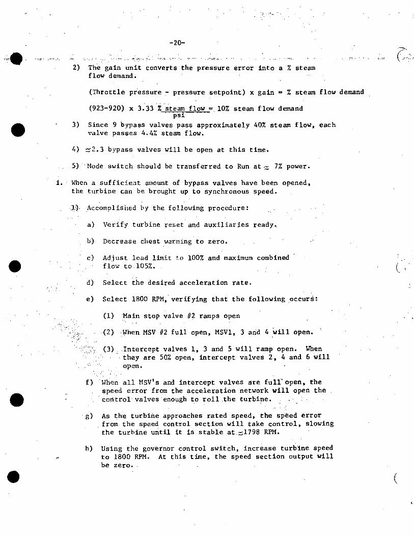
'J ' ... .
-20-
.;.,. __ ""'-"' ----- .. . • -~. _r:.·.~ :-.:c..--
2) The gain unit converts the pressure error into a 7. steam flow demand.
•
•
(Throttle pressure - pressure setpoint) x gain = % steam flow demand
(923-920) x 3. 33 % steam flow = 10% steam flow demand psi
3) Since 9 bypass valves pass approximately 40% steam flow, each valve passes 4.4% steam flow.
4) ::::2.3 bypass valves will be open at this time.
5) ··Mode switch should be transferred to Run at·:;:; 7% power.
i. When a suf fid.e:.i.t amount of bypass valves have been opened, the turbine can be brought up to synchronous speed.
l} Accomplisi1ed by the following procedure:
a) Verify turbine reset and auxiliaries ready.
b} Decrease cl1est warming to zero.
c) Ad_iust load limit t:o 100% and maximum combined flow to 105%.
d) Select the desired acceleration rate.
e) Select 1800 RPM,-verifying that the following occurs:
' L =~ :...•:
(1) ·_Main stop valve //2 ramps open
(2) When MSV //2 full open, MSVl, 3 arid 4 will open.
(3) _ .Intercept valves 1, 3 and 5 will ramp open. When ·they are 50% open, intercept valves 2, 4 and 6 will
open.
f) When all MSV's and intercept valves are fulr open, the speed error from the acceleration network will open the
- cart trol valves enough to roll .the turbi_ne.
g) As the turbine approaches rated speed, the speed error . from the speed control section will take control, slowing
the turbine until it is stable at ~1798 RPM.
h) Using the governor cdntrol switch, increase turbine speed to 1800 RPM. At this time, the speed section output will be zero. -
(
(
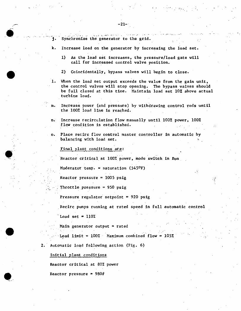
•--
•
-'•
--· . "-- .
•
··,.
-21-'
- -~~- _,_ -- ·~ · .. ·:: . -~ -- = ~- ~-·- .-::-.--
j. Synchronize the generator to the grid.
k. Increase load on the generator by increasing the load set.
1) As the loa4 set increases, the pressure/load gate will call for increased control valve position.
2) Coincidentally, bypass valves will begin to close •
1. When the load set output exceeds the value from the gain unit, the control valves will stop opening. The bypass valves. should be full closed at this time. Maintain load set 10% above actual turbine load.
m. Increase power (and pressure) by withdrawing control rods until the 100% load line is reached.
n~ Increase recirculation flow manually until 100% power, 100% flow condition is established.
o. Place recirc flow control master controller in automatic by balancing with load set. ·,,.
F.inal plant condit.ions are:
Reactor critical. at 100%_ power, mode switch in R~n
_Moderator ·temp. c saturation (5450F) ...
'.·
Reactor pressure = 1005 psig .. f ..
~~· Throttle.pressure= 950 p5ig
Pressure regulatoi setpoint = 920 psig
_Recirc pumps running at rated speed in full automatic control
·· Load set 111 110%
Main generator output "" rated
·Load limit = 100% Maximum combined flow = 105%
2. Automatic load following action (Fig. 6)
Initial plant conditions
Reactor critical at 80% power
Reactor pressure m 980#

. e_,.
•
I.
-22- .
Throttle pressure = 944#
Pressure setpoint = 9200
Recirculation ·pumps in auto at 70% speed
toad set at 80%
Load limit = 100%, maximum combined flow = 105%
Assume a steel mill suddenly is removed from service.
a. This unloading would cause grid and turbine frequency to increase slightly, generating a negative speed error.
b. The speed error is sent to the recirculation system as a flow reduction demand.
c. The· bias and limit network causes an irmnediate setpoint change .to begin closing the control valves.
d. At the same time, the reduction in recirc pump speed causes reactor power and pressure to decrease.
e. The reduced. pressure signal acts as a negative feedback to terminate the rec ire pump speed decrease. 1
·_
·f. Reactor power and pressure stabiliz_e at a new, lower value~
g.-. Turbine load has been··reduced.
h. · Grid and turbine frequency will be greater than 60 hertz but less ~han the init ial··overspeed condition •
.. ;
Final plant conditions ,_... . :\·~~~;, •.,
Reactor critkal at .(80% power
Reactor pressure <980#
Throttle pre~sure < 94411
Pressure setpoint = 920#
Recirculation pumps in auto at <70% speed
Load set at 80%
-Load limit = 100%, maximum combined flow = 105%
r·
,;
(
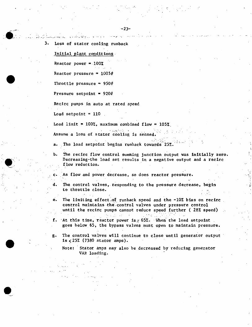
•
• --
-23-
':::"; ~-- '':"-~· .. _: ~-:::·· :-_ --~-- -~~·- -::='":' - -: ·-- -! : .•
3. Loss of stator cooling runback
Initial plant conditions -
Reactor power = 100%
Reactor pressure Q 10050
Throttle pressure = 950#
Pressure setpoint = 920#
Recirc pumps in auto at rated speed
Load setpoint = 110
Load limit ~ 100%, maximum combined flow = 105% ~ r,. :i.: · '· :.. · '~ ·
Assume a loss of stator cooling is sensed.
a. _The load setp~int begin~ runback tow~-~d~;.; Z5%~ ~ _:_ ,_
b. The recirc flow control summing junction output was initially zero. Decreasin-g·-the lo.ad set results in a negative output and a recirc flow reduction.
c. _As flow and power decrease, so does reactor_ pressure.
d. - The control valves,. r.esponding to the pressure decrease, begin to throttle close.
e. The limiting ef feet ,:of run back speed and the -10% bias on rec ire control maintains the~control valves under_pressure control
_until the recirc pumps cannot reduce speed_further ( 28% speed) . ~ ·. . . . ·. . .
f. -At this time, ·reac-tor power is::· 65%. -When the load setpoint goes below 65, the bypass valves must open to maintain pressure.
g. The control valves will continue to close until generator output is < 25% (7380 stator amps) •
Note: Stator amps may also be decreased by reducing generator VAR loading.
-v
• ..,..
.. :··-
•,\- · ..
•
-24---:=-- - --:- ---
h. About 8 bypass valves will have to.be open to maintain pressure.
Final plant conditions
Reactor power = 65%
Reactor pressure·= 96311
Throttle pressure = 939. 5
Pressure setpoint = 920//
Recirc pumps in auto at 28% speed
Load setpoint = 25 . ,.
Load limit = 100%, maximum combined flow = 105%
4. Load rejection response (Fig. 6)
a. EHC control system response to this transient depends upon power level. Three separate co~ditions will be discussed.
1) Power level< 40~~ ·.,
Initial plant conditions .. Reactor power = 30%, generator output = 30%
Reactor pressure = 934# . ~ . r· .... ~: •'. \ ..
, .. ~ . .'..;:.:.-.-f,,,.~· .. ~··,~:.~H·,.,., . .,.,_.,,~ •, '· . ~ " ·; '.-· .c:.Throttle' pressure = 9290
·~.- ~· :~· ::1~ -,. ~.. ,· ~-:. . \. > ''! . ; _1 _·; :.; .~ •
.-. :. Pressure setpoint = 92011
Recirc pumps in manual at 28% speed
Load setpoint = 30 ·.';
Load limit = 100%, maximum '-combined flow = 105%
Turbine RPM = 1800
a) A load rejection occurs whenever the grid cannot accept the power being produced by the generator. For· simplicity, assume the generator OCB's were manually opened.
·[ -· -,~~
•
-25-.. · . ·,
---- ·-,·-~=-·----
b) .Load rejection is sensed by comparing turbine crossover pressure to stator amps.
(1) A 40% mismatch will cause the load rejection · circuit to trip.
c) In this example, since power is only 30%, a 40% mismatch has not been sensed.
d) Upon opening the OCB's, the following occurs:
(1) The turbine is now virtually unloaded and it begins to overspeed.
(2) The speed and acceleration unit senses the overspeed · and produces a negative speed error.
(3) This is summed with. the. load setpoint ·and sent to the pressure/load gate.·-:.'::· ' . _
• • • • • • -: I.,. -· ,'!·.: ! ' :..: , .. :
(4) . With a load setpoint: of ·3'0,~:,~Jn:}r"' ~verspeed will cause the control valves to begin throttling to control the ove rspeed.
(5),
, . .., .. : ·.:: ....
(a) Note that if the load setpoint is at 40, a speed error of more than 9 RPM is required -to begin closing the control valves.
As the control. valves close, the bypass valves will sequentially open to control reactor pressure. ~ . . .
· : ;,J ·c .. ;,.~·(6-f:: .. ,.A' speed err~r of 27' RPM· (L Si.) wlll completely > .. ,·,·.-.· ,>(<,close t~e control valves. .
-. ·,'· - : '
_, .. ' . ~',' 6f- ··Due-' to the· larg~ volum~ of. steam in the moisture separators and associated piping, turbine speed may continue to increase •. . _,, :'
(8) · The intercept valves will begin to throttle to regulate this overspeed •
(9) With a load setpoint of 30, the IV to CV regulation will be 30 (2.5) a 75% •. . . - . ;. ' : _: . :·_; ' -~ ....
-.
ii~·- ' -~-~.,~-i ,r_IJ.; . . ~'. .. --.~·
•
I . l
! I
I . I .e i I I· i
-1 l l
'i 1
•· .. - ~· . -:· :~;':-: i' ''. .•
.·;; ···.!.
, ·.;: ·r :
" '
···~I
-~ I ,••
-26-.I
~- :_. !. - ~~- .· -
~-_.:(11).~ 0 As the. speed error increase•, the IV summing junction output progresaes tovard zero and the intercept valves throttle cloee •
· (12) A speed error of 63 RPM (3. 5%) will c0111pletely close. the intercept valves. The IV summing junction inputs would b~: ·
(a) +100% full open bias
(b) +75% from IV to CV regulations
(c) -175% from speed error dgnal (63 RPM x 2 .• 77)
(13) With the intercept valves fully closed, turbine RPM will begin to decrease.
(14) . This causes the IV summing "junction output to increase in a positive direction, opening the intercepts and
.. blowing down the trapped steam to . the main condenser.
. (15)' :.When this· steam is exhausted,- turbine RPM decreases even further.
(16) 'As the speed error decreases below 27 RPM, the control valves will start to open (assuming load set is still 30).
(17) ·if·. h~use loads are still being carried by tne generator turbine, RPM will decrease until the control valves::
. are passing~ 2% steam flow. This corresponds to a :: J speed error of 25. 2 RPM. . ., ·
. .• 't • .. ·•' .
(18) Th.e bypass valves will be passing~ 28% steam flow.
· - ·· · An. import.ant point to' note is. that the magnitude of overspeed depends upon the setting of the load setpoint. The greater the setpoint, the larger the speed error required to override it.
Final plant conditions ······
Reactor power '= 30%, generator· ·output = house loads (2%)
Reactor pressure = 934U
Throttle pressure = 929#
Pressure setpoint =- 9200
~---·
•
• _ .. _
r • ~ •
•
-27-
. ::-. . - ::::- . - ' - ~ :
Recirc pumps in manual at 28% speed
Load setpoint a 30
Load .lim;lt .,._ 100%, maximum combined flow .. 105%
.Turbine RPM.= 1825. 2
2) Power level~ 40% but <45% (Fig. 6)
Initial plant conditions
Reactor power = 42%, generator output = 42%
Reactor pressure = 942.6#
Throttle pressure= 932.6#
Pressure setpoint = 920// ' ·. .. {' ..... :' : ' • ~ 'I •
:: .. · ... . Rec ire pumps . in. manual at 28% speed.
> • _,,·
Load setpoint .. 42
Load limit a 100%, maximum combined flow a 105%
Turbine RPU =.1800
a) ·In this example, assume manual opening of the generator OCB's. A 40%.mismatch between crossover pressure and· stator amps w:l:ll be sensed, resulting in a load rejection trip •. _
' b) _The load rej_e·ct trip causes the following actions: ...
(1) The load section··output is' gated to zero and the load selector begins a runback ·toward zero.
.. ~~; .
(2) The control valve fast acting solenoids are energized, causing fast closure of the control valves •
(3) .The· bypass control _unit "sees" a steam. _demand of 42% and tries to control pressure by rapidly opening all 9 bypass valves.
(4) The intercept valve IV to CV regulation is gated ... to zero, leaving only the· 100% op~n b;las to maintain
intercept valves open.
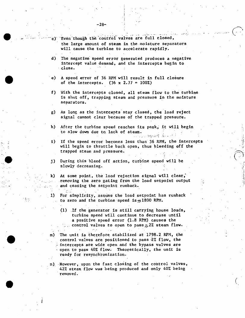
•
".
.. •·
_. ~·- :·
•
'·
-28-
·--·er -Even·-though the 'controf valves ~~e- 'i~ii -~i~sed, the large amount of steam in the moisture separators will cause the turbine to accelerate rapidly.
d) The negative speed error generated produces a negative intercept value demand, and the intercepts begin to close •
· e) A speed error of 36 RPM will result in full closure of the intercepts. (36 x 2.77 = 100%)
f) With the intercepts closed, all steam flow to the turbine is shut off, trapping steam and pressure in the moisture separators.
g) As long as the intercepts· stay closed, the load reject signal cannot clear because of the trapped pressure.
h) After the turbine speed reaches its peak,· ~t will begin to slow down due to. lack of steam.
i) If the speed error becomes less than 36 RPM, the intercepts will begin to throttle back open, thus bleeding off the trapped steam and pressure.
j) During this bleed off action, turbine speed will be slowly decreasing.
k)
. ·. -·;".
At some point, the load rejection signal will clear,· .removing the zero gating from the load setpoint output and ceasing the set:point runback •
1) ·For simplicity, asstime the load setpoint has runback to zero and the turbine speed is~ 1800 RPM.
(1) .If the generator is still carrying house loads, turbine speed will continue to decrease until a positive speed error (1.8 RPM) causes the control valves to open to pass ~2% steam flow.
m) The unit is the~e.fore stabilized at 1798• 2. RPM, the control valves are positioned to pass ~% flow, the
.:.. intercepts are wide open and the bypass valves are , open to pass 40% flow• Theoretically, the unit is
ready for resynchronization •
. n)_ -Hqwever,_upon the fast closing of the control valves, 42% steam flow was being produced and only 40% being
·removed.
,,
J · ..
( '
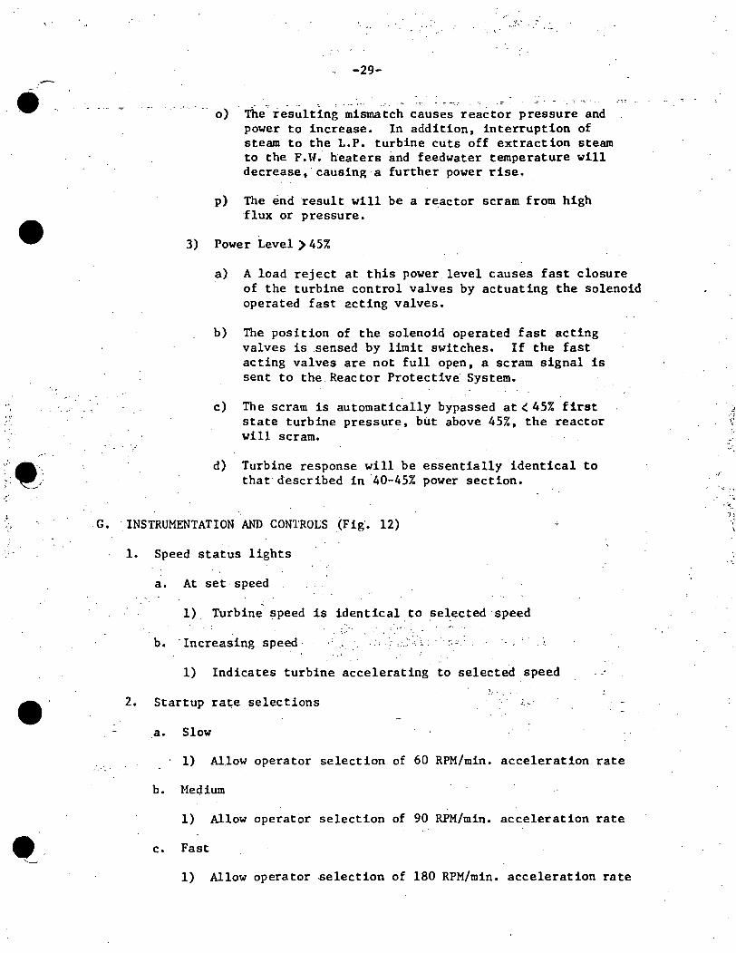
".
----
'" '
•
·."·~-. . . ' ' . ~ • ..I
' ~. ,•
:: H
••
-29-
-- o) The resulting mismatch causes reactor pressure and power to increase. In addition, interruption of steam to the L.P. turbine cuts off extraction steam to the F.W. heaters and feedwater temperature will decrease, causing a further power rise.
p) The end result will be a reactor scram from high flux or pressure •
3) Power Level) 45%
a) A load reject at this power level causes fast closure of the turbine control valves by actuating the solenoid operated fast acting valves.
b) The position of the solenoid operated fast acting valves is .sensed by limit switches. If the fast acting valves are not full open, a scram signal is sent to the Reactor Protective System.
c) The scram is automatically bypassed at< 45% first state turbine pressure, but above 45%, the reactor will scram.
d) Turbine response will be essentially identical to that described in ·40-45% power section.
G. ·INSTRUMENTATION AND CONTROLS (Fig'. 12)
1. Speed status lights
a. At set speed
1) Turbine speed is identical.to selected ·speed
b. ·Increasing speed· ·. , .... .. -. - ,
1) Indicates turbine accelerating to selected speed
2. Startup rate selections .:.:-··
.a. Slow
1) Allow operator selection of 60 RPM/min. acceleration rate
b. Medium
1) Allow operator selection of 90 RPM/min. acceleration rate
c. Fast
1) Allow operator .selection of 180 RPM/min. acceleration rate
.i ··I 1i
". ~ ..
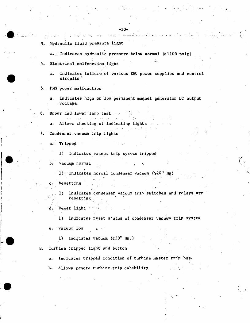
• . I
--
•
-30-
3. Hydraulic fluid pressure light
a •.. Indicates hydraulic pressure below normal (<1100 psig)
4. Electrical malfunction light _:..::;.
a. Indicates failure of various EHC power supplies and control circuits
5. PMG power malfunction
a. Indicates high or low permanent magnet generator DC output . voltage •
6. Upper and lower lamp test --: . ·.· '· .
a. Allows checking of indicating lights ;. .
1~ Condenser vacuum trip lights
a.. Tripped
1) Indicates vacuum trip system tripped
b. Vacuum nonnal
· 1) · ·Indicates normal condenser vacuum ()20" Hg)
c. Resetting
, ~~ .... 1) · Indicates :condenser vacuum trip switches and relays are
resetting~.·
·d. Reset light : · ··>
1) Indicates reset status of condenser vacuum trip system
e. Vacuum low I.
1) Indicates vacuum (<20" Hg.)
8. Turbine tripped light arid button
a •. Indicates tripped condition of turbine master trip bus.
b. · Allows remote turbine trip. cabability
. .,,.
-(·
'<,.
(
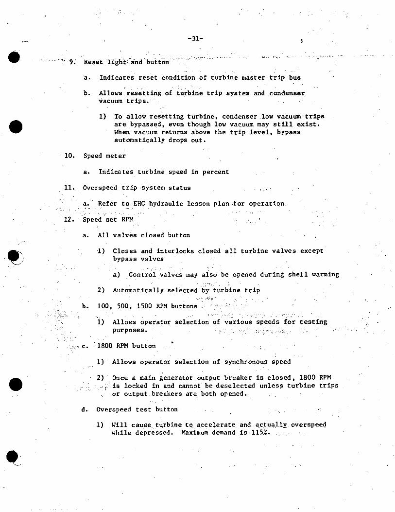
-·
•
•
••
., ....
-31-
- -- - ~- 9.; Reset -Hght: ~and -button.·_--,~··-·> ----·~·-
· .. · :·
.a. Indicates reset conditfon of turbine master trip bus
b. Allows resetting of tu_rbine trip system and condenser vacuum trips.·
1) To allow resetting turbine, condenser.low vacutan trips are bypassed, even though low vacuum may still exist. When vacuum returns above the trip level, bypass automatically drops out.
10. Speed meter
a. Indicates turbine speed in percent
11. Overspeed trip ·system status
a. - Refer to. EHC hydraulic lesson plan for operatiqn, "'·• ·.· ..
• · . · .. ·.·· t · .. ,. . ..
12. Speed.set RPM
a. All valves closed button
1) Closes and interlocks closed all turbine valves except _bypass valves
a) . Control ;valves may_ also be opened during shell warming
2) Automatically selected by turbine trip
b. 100, 500, 1500 RPM buttons ._..,,_ .. :.; . '
.... ! .:· ..... :_ l.: ·::' :-..
i) Allows operator selection of various speeds for testing purposes.
-· .. -~;~' c. · 1800 RPM button
. .r· .. ~.
1) · Allows operator selection of synchronous speed
2) · Once a main generator output breaker is closed, 1800 RPM . __ ,,: is locked in and cannot be deselected unless tur_bine trips
or output. breakers are both opened.
d. Overspeed test button
1) Will cau,se __ turbin~ tq accel,erate and actua,lly. overspee<;i while depressed. Maximum demand is .115% •
,._
., .

. '
.e
• ..
;,
•
~ ;
... ·•
,,
f -32-
·/
13. Main stop valve position deinand for chest warming
·a. Indicates main stop valve position from 0 -+100% for shell and chest warming. · Actual· stem movement is only ·:~10% of full travel. · ··
14. Chest. warming selector
a. Increase and decrease buttons
1) Allows operator to position #2 stop valve for shell or chest warming purposes
b. Chest.warming light
1) Indicates 112 stop valve is being used 'for chest warming·
Note: At Dresden, this is both a light arid a button.
c •. Off· light
Depressing the button selects the shell warming . feature.
1) . Indicates no chest or shell warming in progress.
Note: At Dresden, this is a light and a button. · Depressing the button deselects the shell
warming feature.
15. Main Steam Pressure "A" & "B"
Indicates turbine throttle pressure inputs to EHC control system. ~ < •••
·'' . :.-. , . ·. ~ . it).:
16, Pressure .setpoint "A" & "B" \
a. Indicates pressure setpoint selected by operator. · Ranges from 150 to 1050 psi. - ~ ;
.. · •: ' : .
b. Setpoint selected by increase/decrease buttons . . .· . ._·, · ..
-c. one setpoint is normally biased 10 psi ··higher than the other.
Lights indicate which setpoint is the contro~ling one.
17, Bypass opening jack and selector . ;.-
· ·a. ··Indicates % ·bypass -valve demand. 100% would correspond to all.nine bypass valves open.
b.
c.
~ ..
Increase and decrease buttons position byp~ss: ~aives >f.·
Open and closed lights indicate full open or full closed · bypass valve signal.
. .. -
•
: t.
·/ ::- .
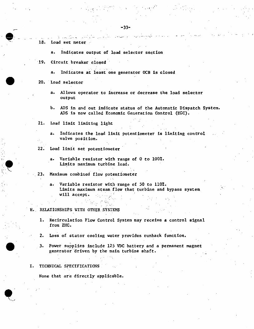
. '·
•
.. ·.
.:•.
•
-33-
..• .:. . .: :--- ~·. ··-.-·
18. Load set meter
a. Indicates output of load selector section
19. Circuit breaker clo~ed
a. Indicates at least one generator OCB is closed
20. Load selector
a. Allows operator to increase or decrease the load selector output
b. ADS in and out indicate status of the Automatic Dispatch System. ADS is now called Economic Generation Control (EGC).
21. Load limit limiting light
a. Indicates the load limit potentiometer is limiting control valve position.
22. Load limit set potentiometer
a. Variable resistor with range of 0 to 100%. L.intits maximum turbine load.
23. Maximum combined flow potentiometer
a. Variable resistor wit.h range of 50 to 110%. Limits maximum steam flow that turbine and bypass system will accept.
·. ··:· :'.' .'.,;•,
. ~ ... H. RELATIONSHIPS WITH OTHER ·.SYSTEMS
1. Recirculation Flow Control System may receive a control signal from EHC.
2. Loss of stator cooling water provides runback function •
3. Power supplies include 125 VDC battery and a permanent magnet generator· 'driven by the main turbine shaft.
I. TECHNICAL SPECIFICATIONS
None that are d·irectly a·pplicable.
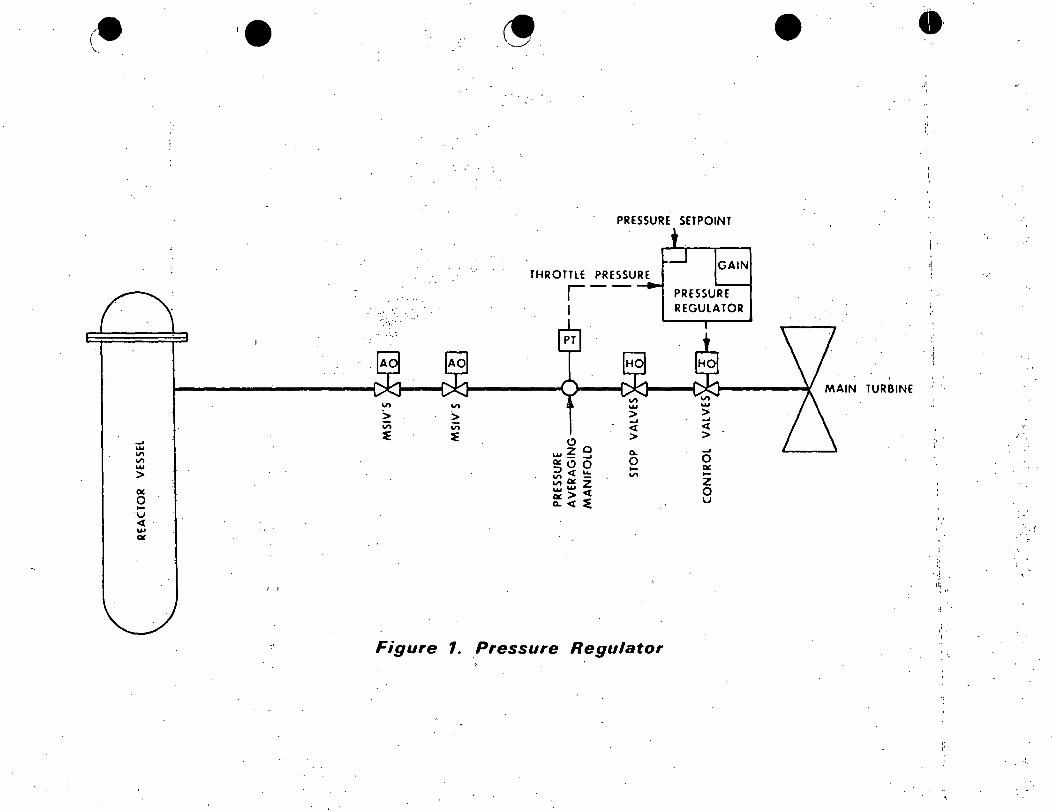
(-' ·
.... ..... "' .,.. ..... > a: 0 .... u < .., a:
I I
.,.. .,.. > > .,.. v; ~ ~
PRESSURE SETPOINT
THROTTLE PRESSURE ,--1
.,.. w > .... .:i:
<:> 0 >
..... ~ .... 0..
QC <:> 0 0 ~.:i: ~ .... .,.. .,.. QC z .......... < IX>~ 0.. <
PRESSURE REGULATOR
.... 0 IX ....
.z 0 u
Figure 1. Pressure Regulator
• _.I
i
TURBINE
' .
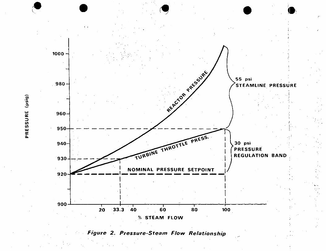
w a: ::::> (/) (/) w a: a..
1{)00
'980
960
950
940
930
920
·. ,, .
----------. .
20 ·33.3 40 . 60 80 100
% STEAM FLOW
Figµre 2. Pressure-Steam Flow Relationship
55 psi
., ·'
STEAMLINE PRESSURE
.. ·i
30 psi
PRESSURE REGULATION BAND
,l
" : ·,
.! ' ~ . .
: • l
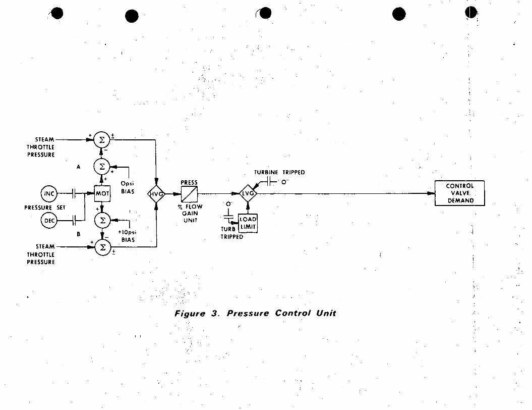
+ STEAM----•
THROTTLE PRESSURE
A
@---1.,__, ..... PRESSURE SET
~ 8
STEAM -----i THROTTLE PRESSURE
• I'
Opsi BIAS
+10psi BIAS'
±
I
PRESS
3 FLOW GAIN UNIT
... . ...
. "··
Figure
.. I
. "
• ..
TURBINE TRIPPED
~ .. o·· .. CONTROL
VALVE. DEMAND
TRIPPED '•
•'
;) .
3. Pressure Control Unit .'•.
"
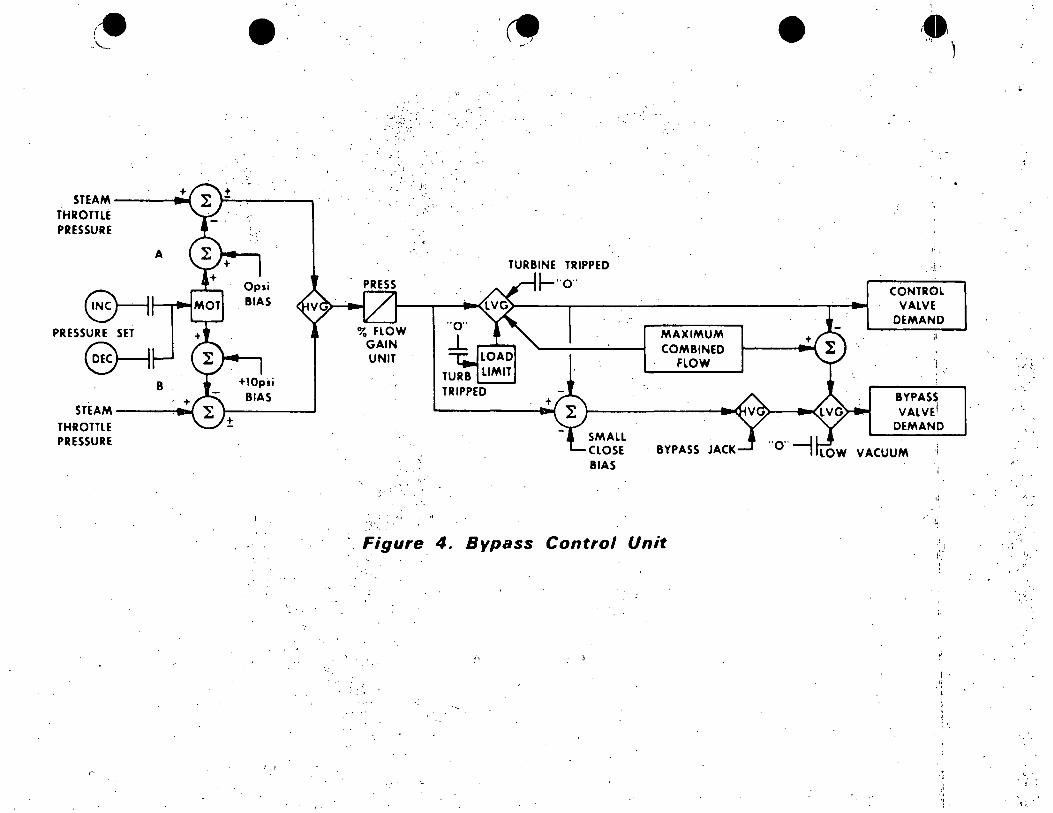
+ STEAM----111
THROTTLE PRESSURE
A
E)--11--. ...... PRESSURE SET
8---1 B
STEAM ___ _,,..,.
THROTTLE PRESSURE
+
•
··:
Op1i BIAS
+lOpsi BIAS
I I
. . . .· .. '.>· P;'
PRESS
3 FLOW GAIN UNIT
. \.
.< .
TRIPPED
TURBINE TRIPPED
~··o ..
+
SMALL CLOSE BIAS
MAXIMUM COMBINED
FLOW
· BYPASS JACK
Figure 4 .. Bypass Control Unit
•
CONTROL VALVE
DEMAND
l . '
BYPASS VALVE!
DEMAND
VACUUM
I,
.'i I
., ·' ., ·1.
''
;~ .
' ~· :
,_.
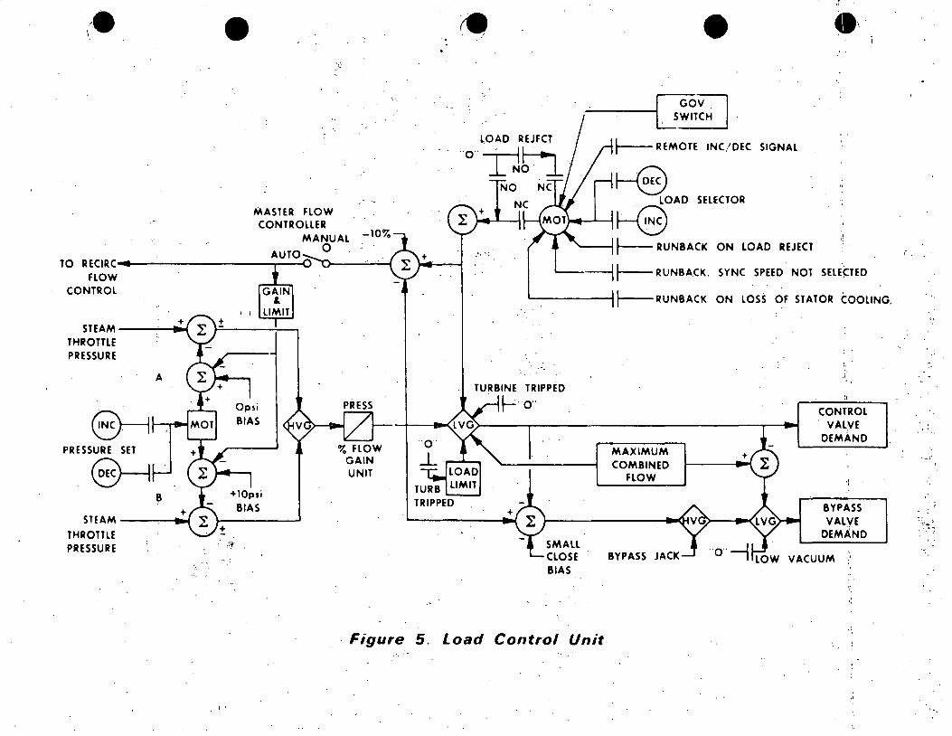
•
MASTER FLOW CONTROLLER
MANUAL 0
TO RECIRC----------.,.---u FLOW
CONTROL
+ STEAM-------'
THROTTLE PRESSURE
A
8---1·..._.,...-4 PRESSURE SET .
.~ ~
STEAM----~
THROTTLE PRESSURE
. I'
Opsi
BIAS
+lOpsi BIAS
": - ..
+
TURBINE
~
+
• ~---~G~~~H I .
..._ __ REMOTE INC/DEC SIGNAL
~ LOAD SELECTOR
"---"~~ '---....1 ~ RUNBACK ON LOAD REJECT
. ,,
--1 r-- RUNBACK. SYNC SPEED NOT SELE~TED
L-------l~RUNBACK ON LOSS OF STATOR COOLING.
'"
TRIPPED
o··
SMALL CLOSE BIAS
MAXIMUM COMBINED
FLOW
BYPASS JACK
CONTROL VAL.VE
DEMAND
BYPASS VALVE
DEMAND
VACUUM
Figure 5. Load Control Unit
. -;
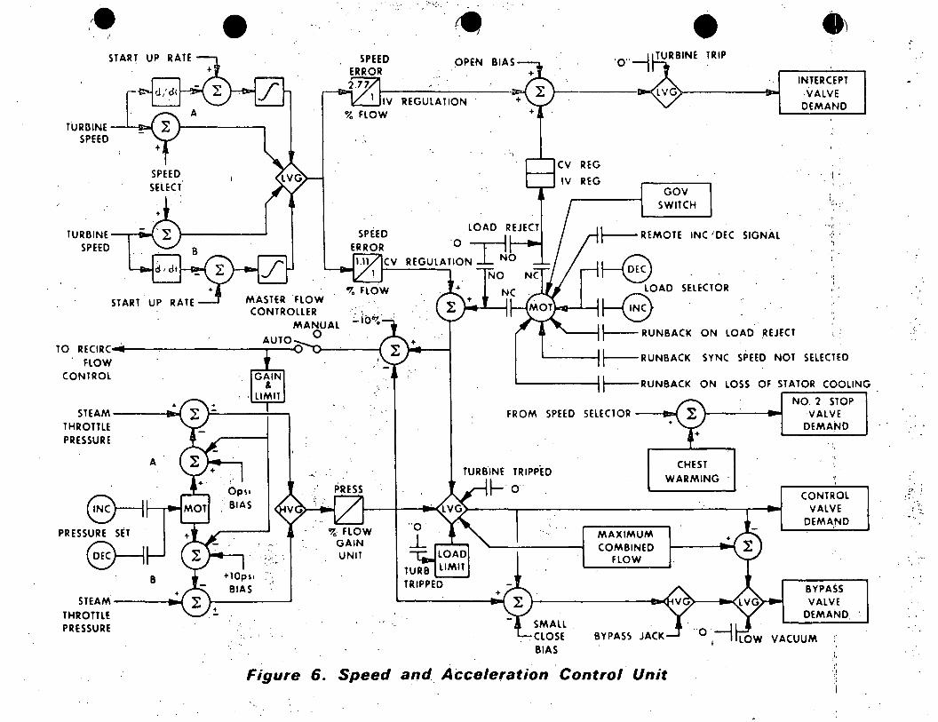
.~
TURBINE SPEED
TURBINE-"T"""'Dll9ol SPEED
• SPEED ERROR
3 FLOW
SPEED ERROR
. · . .,·
CV
% FLOW M.ASTER FLOW CONTROLLER
MANUAL . ::._ lO'(
Ops1 . BIAS
0
···-
;:. :.~ .
4 OPEN
REGULATION
+ .
REG
REG
•
GOV SWITCH
TRIP
i----REMOTE INC 'DEC SIGNAL
~ LOAD SELECTOR
~--.~0-..._-i ~
.) INTERCEPT ·VALVE DEMAND
'.•
"'' .,
•: ' ,'.
---1t-- RUNBACK ON LOAD .REJECT t..
'------i~RUNBACK SYNC SPEED. NOT SELECTED
------1l---RUNBACI< ON LOSS OF STATOR COOLING
FROM SPEED SELECTOR --tt8"1
NO. 2 STOP ·VALVE DEMAND
TURBINE TRIPP.ED CHEST
WARMING ~·o ..
+
SMALL .
MAXIMUM COMBINED
FLOW
. CLOSE BYPASS JACK BIAS
CONTROL VALVE
DEMAND
BYPASS VAL'llE
DEMAND
VACUUM
Figure 6. Speed and Acceleration Control Unit
'
.. · .
·;-,.: :. .
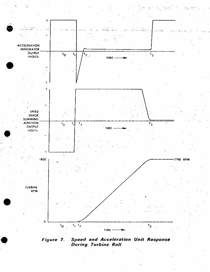
-
•
•
••
-.:: .. ~-: -
ACCE~ERATION
INTEGRATOR OUTPUT IVOLT!l.i
SPHD ERROR
..
'i
,,
.. - ~- -~-~· .--- . -- -- ...... -~·
'o 11 TIME ...
SUMMING __ +----~~+--~-~--~~-~-~~~~~_..::==========; JUNCTION
OUTPUT iVQLI~·
TURBINE RPM
'o TIME-~ .. ..,_-
1800 ..,..-.,------17 98 RPM
0 le) l
J. ' TIME ..,_
Figure 7. Speed and Acceleration Unit Response . During Turbine Roll
•.··· ...
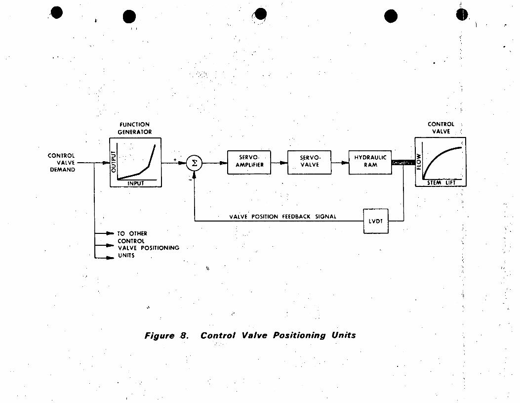
• I I
FUNCTION GENERATOR
co~~~~~ ---...--e-~ .... o~I · ..• ·. . j i---•_.,-4 -~ DEMAND ~
~ ·'
INPUT
1--~ TO OTHER CONTROL
1--... _. VALVE POSITIONING
'---_._. UN ITS
' ~ - '
SERVOAMPLIFIER
S_ERVOVALVE
VALVE POSITION FEEDBACK SIGNAL
• ,i
•• 1:'
CONTROL ,, VALVE
HY~~llC :--·~~ STEM LIFT
LVDT -:
;
" ,,
.1;
'i!
Figure 8. Control Valve Positioning Units .,
,•
;.,.
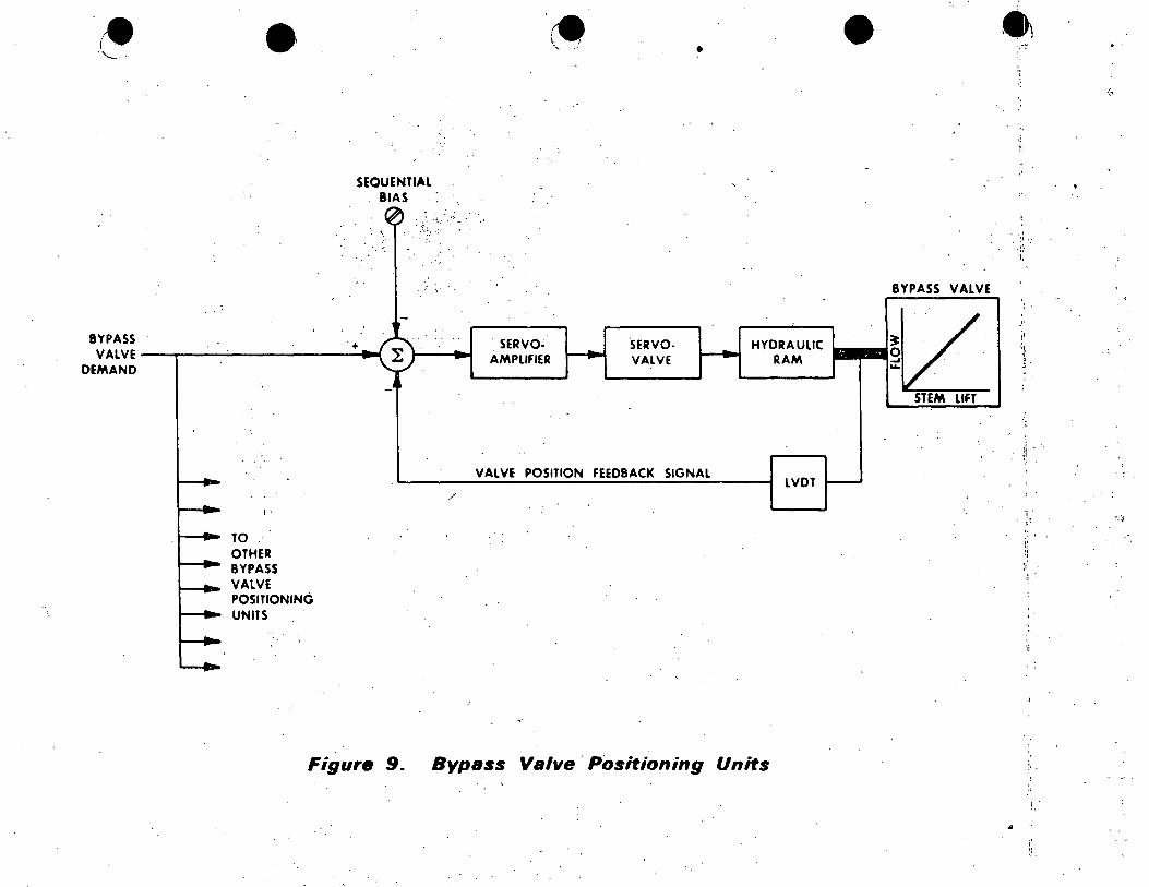
SEQUENTIAL BIAS
: •.
BYPASS ·+ VALVE~--.~~--------~----~~
DEMAND
I'
TO OTHER BYPASS VALVE POSITIONING UNITS
Figure 9.
• •
BYPASS VALVE
. SERVOAMPLIFIER
·sERVOVALVE
HYDRAULIC ~I . ' / . RAM --~L
STEM LIFT
VALVE POSITION FEEDBACK SIGNAL LVDT
/
Bypass Valve · Positioning Units
' .; ·.:;.
1,
'•. '
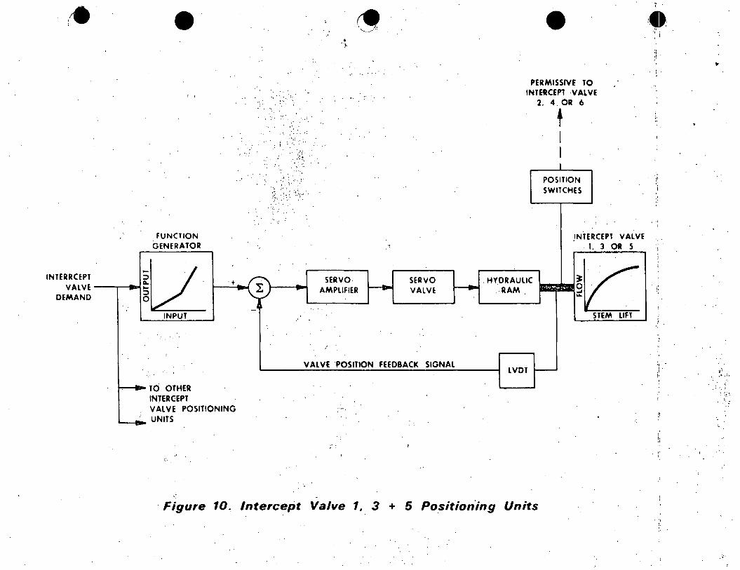
INTERRCEPT VALVE
DEMAND --
.. -
• I I . . : .
" .
···. -:·.; .,
··~·
. : I :··'( ·: ; ..
~. ~? ~~ . '
... ' !·· .. ... . ·. ~ . ..
:' ~
:;;\~I·:.~ .. ··;.:
'
FUNCTION GENERATOR
tL SERVO· SERVO 0. . ·t ~ - r--c- i----.... - - AMPLIFIER VALVE '.:)
0 - a
INPUT
VALVE 'POSITION FEEDBACK SIGNAL
TO OTHER INTER•CEPT VALVE POSITIONING .. ,.
UNITS
• PERMISSIVE TO
INTERCEPT ·VALVE 2. 4.0R 6
t I I I
POSITION SWITCHES
.INTERCEPT VALVE . 1, 3 OR s
~~ .HYDRAULIC 0 . .RAM _, ...
STEM LIFT
LVOT -
.
·Figure 10. Intercept Valve 1, 3 + 5 Position'ing Units·
'( .
. " I
~.
"
. v: . •. ,r..f"
. , ~.
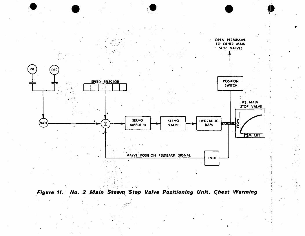
• .....
' ...... ~-"' ' ·:
I I
SPEED SELECTOR
+
+
· .. ·.:
. · .'• ....
. ,j
SERVOAMPLIFIER
SERVOVALVE
VALVE POSITION FEEDBACK SIGNAL
.. ,
• OPEN PERMISSIVE TO OTHER MAIN
STOP VALVES
4 I I
POSITION SWITCH
.#2 "MAIN STOP VALVE
HYDRAULIC ~I ./ ~-R-AM_!••gL__
STEM LIFT ·
LVDT
Figure 11. No. 2 Main : Steain, · Stop Valve Positioning Unit, Chest Warming I'
: ... •'--~: ,·-·-:
.•
·9' ' ' I J
...
.i·
·-:_t
, . . 1·
" .; .
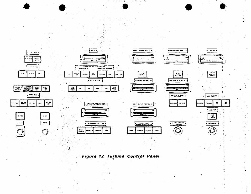
,..
IDEI:JI ""~au\IC
'\U10 ,.IHU"f
tllCllhCAl
~ ... ,,Ull(ltQtll
T••i.t.D VA(U\,111 -·
...... ...... TUI
. ., ... ""'
•
I I
· .. ;.··
•,i.
I'
°"" ......
: /•
trftO\IT•._ 3
lc=JI •»» ....
••• \T()P v&LV( ll'QS•11()11
01 ... "D 'Dl'I CM(IT ••-llC
G*ll ..
Figure 12 T11.rbine ~-~·
~lfl~TU•~USUlll . j
Q;. .. , ~: iIJ "''
·~1 Nj '·Ii h ~UtCUT
CUJllD
Control Panel· ...
• 9'· ·; \
t.a11t \TtAlf NU"""' I~ ~ lOAOUt j
~·· ·ID .\t! ~~cun ·~1 "''
I
E ... (UIJll( H T"OtttT •·· 1
IT•m:::-=i;;;:::::::. =· ID 1,.· ... ·#-
F ·-·-· -~ LOID ..... ·1. •·
t,.mTllltG
t-.1-..CC..IMD j FLQ&O--TSlT3 rLOJLmT ~' ~
@ @ ., .
._,
-:
.,
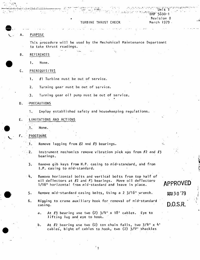
~ ~ ,/~"'.Lt'~
'·· '· . I •
~!'-....;.....;..:..,.....; ... _;. ...... .:.._:.;..·:.:~--=:~::.:. .. : .. :.:.~-~. . . . .. • : .. :·.: ..•. -: : • .• ~ .• ·.·.- 7 -:_ - -.~ti~ ft' -:.1 '·-·.:,· -~ ~ ·. ;,.7 : ~-,--. ~ •• _,. ••· .
•
--· ··: ·. ·. ··. · _;··:~. :·,..·,.:· ··· -.~_,,~--·,=c>;:rr> :5600-1 ·· · · - ·
TURBINE THRUST CHECK Revision 0
March 1979·
\._ .· A. PURPOSE
•
'-.
This procedure will be used by the Mechahical Maintenance Departemnt to take thrust readings.
B. REFERENCES
1. None.
C. PREREQUISITES
1. #1 Turbine must be out of service.
2. Turning gear must be out of service.
~3. Turning gear oil pump must be out of service.
D. iPRECAUT IONS
1. Employ established safety and housekeeping regulations.
E. ~IMITATIONS AND ACTIONS
F.
'1 .• None .
. PROCEDURE
1.
.... 2.
3.
li.
Remove lagging from i2 ~nd_ #3 bearings.
Instrument mechanics remove vibration pick ups from #2 and #3 bearings.
Remove gib keys from H.P. casing to mid-standard, and from l.P. casing to mid-standard.
·:-r...
Remov~ horizontal bolts and vertical bolts from top half of oil deflectors at #2 and #3 bearings. Move oil deflector~ 1/1611 horizontal from mid-standard and leave in place. APPROVED
s.
6.
Remove mid-standard casing bolts, Using a 2 3/16 11 wrench.
Rigging to crane auxiliary hook for removal of mid-standard casing.
a. At #3 bearing use two (2) 3/li 11 x 18 1 cables. Eye to 1 ifting lug and eye to hook.
b.
. .
At #2 bearing use two (2) ton chain falls, two 3/li 11 x li' cables, bight of cables to hook, two (2) 3/li 11 shackles
I 1
~30 '79
D.O.S.H.
' ~I I
t
(
' I
' ).
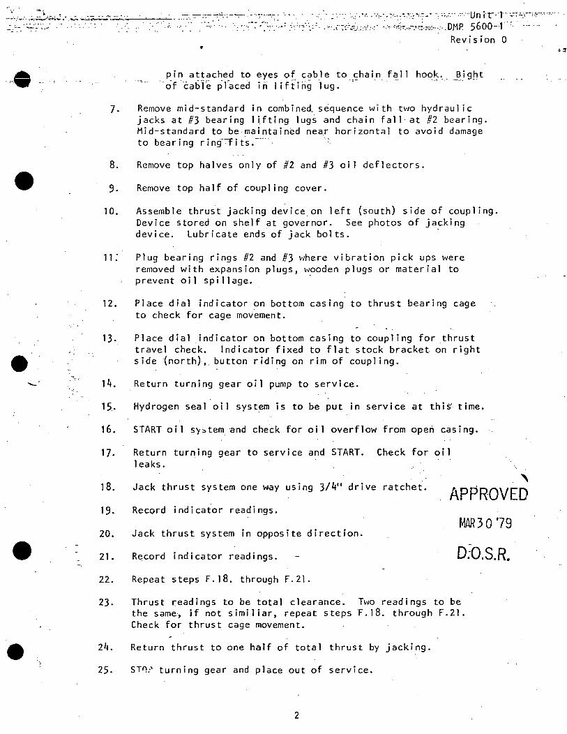
·--~~:'y:·.::.?:_.~;..;-~ .;..-:. ... ~~~----~~- .. '.-:-: ~ c:- ~'~-~-~-~:...:~~--~:-;.~.:.; ·"_:::,:-.··_; ~-:· ~-~~.:~--~~c~~-:·:; :'-~·::·<·:~-;~--~~_:;::.~·'.:'.: .. ~M-~ --~~~~~·:r· ~~==.:;·-,.-"._,_, .,_ ....
... 9 .. ·.
•
;,
•
Revision 0 •
pin attached to eyes of cable to chain fall hook. ~ight of.cab"l'e pl'acedin lifting lug. ··-
]. Remove mid-standard in combined s~quence with two hydraulic jacks at #3 bearing llfting lug~ and chain fall at #2 bearing. Mid-standard to be maintain~d near horizont~l to avoid damage to bearing r i n~f-:-f i t.s :·· · · ·
8. Remove top halves only of #2 and #3 oi 1 deflectors .
9. Remove top half of coupling cover.
10. Assemble thrust jacking device on left (south) side of coupling. Device stored on shelf at governor. See photos of jacking device. Lubricate ends of jack bolts. ·
11: Plug bearing rings #2 and #3 where vibration pick ups were removed with expansion plugs, wooden plugs or material to prevent oil spillage.
12. Place dial indicator on bottom casing to thrust bearing cage to check for cage movement.
13.
14.
15..
16.
17.
Place dial _indicator on bottom casing to coupling for thrust travel check. Indicator fixed to flat stock bracket on right side {north),. button riding on rim of coupling.
Return turning gear oil pump to service.
Hydrogen seal oil system is to be put in service at this'- time.
START oil sy~tem and check for oil overflow from opeh casing.
Return turning gear to service and START. Check for oil 1 ea ks.
' 18. Jack thrust system one way using 3/4" drive ratchet. APPROVED 19.
20 •
21.
22.
23.
24.
Record indicator readings.
MAR30'79 Jack thrust system in opposite direction.
Record indicator readings. o:o.s.R. Repeat steps F. 18. through F.21.
Thrust ~eadings to be total clearance. Two readings to be the same~ if not similiar, repeat steps F.18. through F.21. Check for thrust cage movement.
Return thrust to one half of total thrust by jacking.
25. ST~? turning gear and place out of service.
2
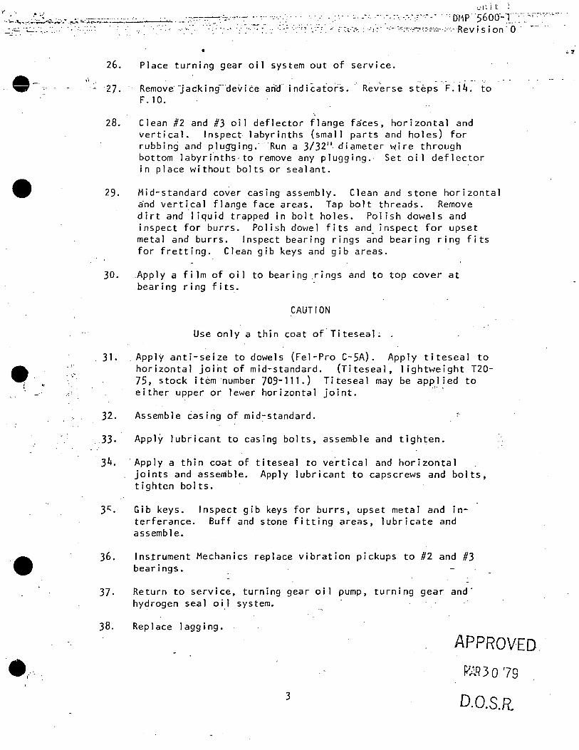
y• 4 •• • • .'
-·-:- ~~~-·~:.:~..,,..::-.~- .. - ·~--:.;. ~'.·;~=..:~·~ ·-· --- -:·-·····
.. e ~-
•
e ........ :
• e .. ··.
• 26. Place turning gear oil system out of service .
27. Remove··jacking-·device an_d. indicafors. Reverse steps F.14. to F. 10.
28. Clean #2 and #3 oil deflector flange f~ces, horizontal and vertical. Inspect labyrinths (small parts and holes) for rubbing and plug-ging.···Run a 3/32"- diameter \.,,ire through bottom labyri~thscto remove any plugging .. Set oi 1 deflector in place without bolts or sealant .
29. Mid-standard cover casing assembly. Clean and stone horizontal a·nd vertical flange face areas. Tap bolt threads. Remove dirt and 1 iquid trapped in bolt holes. Polish dowels and inspect for burrs. Polish dowel fits and inspect for upset metal and burrs. Inspect bearing rings and bearing ring fits for fretting. Clean gib keys and gib areas.
30. .Apply a film of oil to bearing .rings and to top cover at bearing ring fits.
CAUTION
Use only a thin coat of Titeseal.
31 .. Apply anti-seize to dowels (Fel-Pro C-SA). Apply titeseal to horizontal joint of mid-standard. (Titeseal, I ightweight T20-75, stock item ·number 709-111.) Titeseal may be applied to
• ~- t
either upper or !ewer horizontal joint.
32. Assemble casing of mid-standard.
33. Apply lubricant to casing bolts, assemble and tighten.
34. ·Apply a thin coat of titeseal to ve~tical and horizontal joints and assemble. Apply lubricant to capscrews and bolts, tighten bolts.
3~. Gib keys. Inspect gib keys for burrs, upset metal and interferance. Buff and stone fitting areas, lubricate and assemble.
36 .
37.
38.
Instrument Mechanics replace vibration pickups to #2 and #3 bearings.
Return to service, turning gear oil pump, turning gear and· hydrogen seal oi,I system.
Replace Jagging.
APPROVED ..
fi~q 3 0 '79
3 D.0.S.R.
'-..·::·
•
-l
. \......'.'
•
.. I
G. CHECKLISTS
1. None.
... . .. : ...
_.,_ ··-···-.-~ :· ·. ·. ·._· -. ····· · --· -: ·.::, .. -... _,_~<:-·:··,··u11ft'"T·.-.--~-~-~~~,,,-_~---., -· · ·: ·:·· ·. ·- · · ... ·: ·.·. ': · .. · ... _.._ i ;, -:~.· :":-'":·-- -.·· -:~~:~,.,.~,:-~·oM·P. 5600-1 · ..... .
Revision 0
H. TECHNICAL SPECIFICATION REFERENCES
1. None .
~ ( f i na 1)
.APPROVED.
c;';i-; Q '79 r- ..... 1)
D.0.S.RD
•
e.
·-
..
. -:-- -:--:--- -~ -
TllRBIKE COl1PLING MAINTENANCE
. > ~ . ,.. ~. '·
D!·P 5600.-4 Revisi9n 0
·· r·ebruc.ry 1980 _,
A. PURPOSE
B.
The purpose of this procedure is t.o provide instructions for turbine coupling_ aligrirnent check and bolt-up .
REFERENCES
General Electric Turbine Manual.
C. PREREQl1ISITES
None.
D. PRECAFTIONS
None.
E. LIMITATIONS AND ACTIONS
F.
Rotor position changes to favor coupling alignment are only to be made with the approval of the Assistant Supt. of Maintenance.
PROCEDLTRE ,· ..
1. Alignment check . ~~;-
a. START Bearing Lift Pumps and rot.ate coupling halves to align ~atch marks at the 12 o'cl6ck po~ition. Then shut down Bearing Lih P.umps.·
h.
c.
Attach dial indicators to D coupling as shown in fig. 1 at the 12 o'clock and 9 o'clock positions. One magnetic base dial indicator mounted at the 12 o'clock position is sufficient for A, B and C couplings.
Take -a reading between the coupling faces. at· the 12, 3, 6 and 9 o'clock-positions.
c!. The initial "rim" check at the 12 o'clock position will be a zero readin~.
I of 9
APPROVED FEB 13 '80
D.0.S.R.
"
t t t ·~ J
Ci \);.
•
2.
•
D}jp 5600-4 Revision 0
e. START Bearing Lift Pumps and rotate coupling halves. together 90° clockwise. Shut down Bearing Lift Pur:lpS.
f. Take 4 face readings as in Step 'c'.
g. Take a "rim" reading \dth the dial indicators in this position.
h. Repeat Steps e-g until reading~ have been taken at 4 rotor positions .
i. START Bearing Lift Pumps and rotate coupling halves to initial position in Step 'a' and RECHECK indicator zero.
NOTE
General Electric recomnended limits for coupling alignment are: face readings are to be witt:in .001" of parallel in the horizontal direction and the rim readings concentric "Within . 002". Past· variations from this tolerance are shown in Appendix A for each turbine coup ling ..
j. Notify Control Room Operator that Bearing Lift Pumps may be shut down or ·left running as desired by the Operations Department.
Coupling bolt~up
a. Rotate coupling halves to align match marks and install spacer plate.
b. Choose a set of bolt holes 180° apart for which we have tapered alignment pins with no more than .001" clearance. Apply Molykote or equivalent. and INSERT pins. "' ..
NOTE
If .001" clearan~e pins are not available, they shall- be machined for this fit.
c. Select 4 undersize studs with 15-30 mils clearance and Il~SERT at 90° intervals .. Pull coupling halves together and tighten studs evenly.
d. With diat indicators mounted on casing, take a runout . check on both coupling halv~s at 4 rotor positions minimum. - Runoct on either coupling half should not exceed .001" and the total differential at any point should not exceed . ooi:s 11
• .
2 of 9
APPROVED FEB 13'80
D.O.S.R.
I..,

--- . -----~~·--
•
...
• e·
...... m:P 5600-4 Revisio:i 0
e. If reading is beyond. limits:
__ i..:.·,_ RECHECK ·di-al· ind"icators ·and readings.·
2.· If necessary, RECHECK sizing of alignment pins, loosen the 4 studs and evenly retighten. REC!iECK runout.
f. Coat fitted stud bodies \."'1th lfolykote or equivalent, install studs and sequence tighten about one half of the studs (stretch 26 to 30 mils for A, B, C and 40-44 mils for D).
NOTE
Stud fit is to be 1 to 3 mils clearance in the respective hole. Hone hole or replace stud if necessary to obtain this fit.
g. RECHECK runout as in Step 'd'.
h. If reading is beyond limits - relax fitted studs and retighten as in Step 'f'.
i. Continue to stretch the remainder of the installed fitted studs.
j .
k.
Remove alignment pins and undersize studs,· replace with fitted studs and tighten as in Step '°f"'.
Take final runout check and RECORD results •
G. CHECKLISTS.
1. . Coupling Runout.
2. Clearance &-_Alignment.
3. Coupling Bolt Fit.
3 of 9
APPRC1VED FEB 13'80
D.0.S.R.
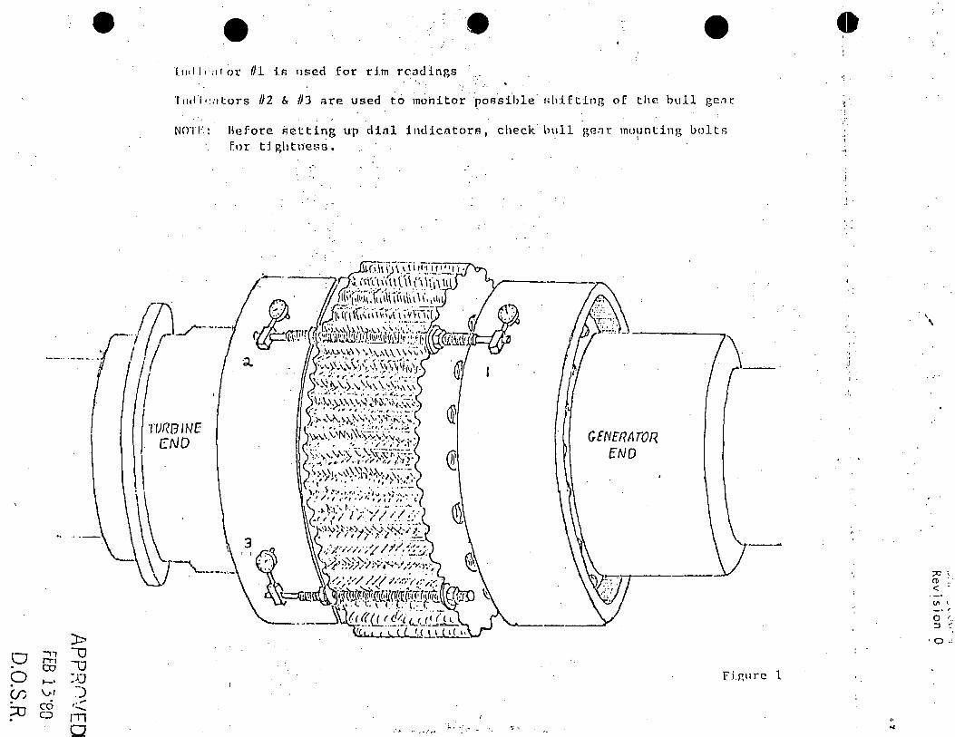
)>
0 ..,, -0 rr-1 u co
0 ~·
:JJ (/) \J.J ~)
;o co ~:..::: CJ rn
0
•• • l11ill1·;1lor Ill i.fl used .for d.m rcacllngs
T11dl•·:itors /12 & /)J ::irP- used to mohitor.pofl-sible' Hh:lfting o[ the bull gc.'.l(
NOTI·:: Before F>etting up dinl indicators, check· hull p,erir mu11nting bolts I ..
F.or tightrle!~G.
/7\ r---·-"1 ( r·-/ I : I '! /
TURBINE CND
.. .. -~ / ..... ; i·· ·· ... ";.-.
GENERATOR f ND
\_.·.
fi.r,11rc l
•;'
'I··
'.
.. ~
\
;:IJ : .. ro ... < -V'I \
-· f 0 r ..
::J r::
·o.:
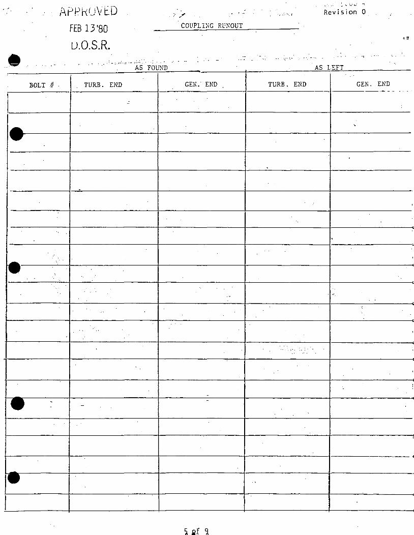
BOLT ti .
APPk(.)VtD
FEB 13 '80
u.O.S.R.
TURB. END
COUPLING Rl~l'WUT
GE!\.· END
•. · .. : . : ' '-' lJ
. •,,., ... ' Revision 0
AS lEFT
TURB. END GEK. END ------·l-----------l'-----'---------4---------- ------- ·-·- - - ... I
I ~~-----+----'---------1----------t---------~-------·~-+-~~-f-~~-f-~~-+-~~

,,.-. I
e
f£B l.3 '80·
Q.O.S.R.·
COUP~G CHECK
. . · __ COL'"PLING
BRACKET . OR INDICA
TOR 110L1'.lED ON SIDE OF COUPLING
-CO.UPI.ING ·
13RACKETOR INDICA-
TOR MOII'.'ffED ON .SIDE
OF COUPill:G
AS FOUND
Unit NCj;
AS LEFT
NOTE: C!iECK TO EE TA~N l.DOKD:G TQ'.',"A?..D GE.\TR..\ TOR. E:i'."'TER A\TR.;G:: OF F'Ol;"R 909 COlJP~G CHECKS .
P::Rl?H!:RY
NOTE: CHECK '.TO BE T.-LX.:::X IDOKL.'liG . TOWARD GENER.~ TOR. E}j"'TER A VEP~.GE OF. FOUR 90° COUPLING CHECKS.
DMP 5600-1.i Revision 0
~---: - --=.
BRACKET OR L'-"'DICATOR !\-IO lTKTED ON SIDE OF COuPLTh'G
---COUP LTh'G
PERIPHERY
BR.ACK.ET OR L'IDICA
TOR MOU:t\"TED -ON SIDE
OF COUPLING
1. Coupli.11gs to be ali:;nee in accorc:i.ncc witb be::.rL"6 aUg-r:Jnt:nt c!2;:-=i• ar.:! wiU-1 all upper hal! t:i.sings asserr:bled ar.d bo!!c-d. P.e!er to coupling assembly instructicns for i1civid;!.11 ur.it.
2. Periphery checks inust ~ "i!hin 0. 002 in. of expected \"J.lue s:io.,,·:-: c:::U:.e b-e:iriq; al.i~ment dr.iwbg. Faces are to !Jc ::.U.gned 1.:ir:illel ho•izo;:ullv -..·ith.i..'1 0. 001 in.
3. Rotor position ct..J.nges to fa\"or coupling al.!gr~-r.en~ :ire only to ;;e r.!~~ w!th er.;;:nee:-ing :i.;::;>ro·.-::i.l.
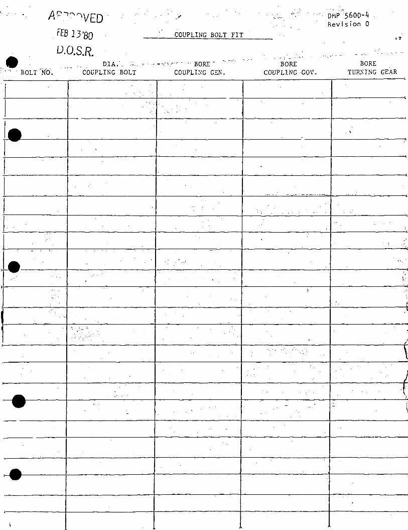
·.i
A c-.1 ""VED · FEB 13'80
0.0.S.R. DIA:o
COliPLING BOLT
COUPLING BOLT FIT
~: .. ----.
. COUPLI:\'G GEN.
.. · .. ::· ·,
.........
::. .- ~ - - .
BORE COUPLING GO\'.
D~1P-"5600-4 Revision 0
.-· .. ::
BORE TUR.'\ING GEAR
. ~
t-·-··. t---------+-··" ----+-----+-----'~,' II . ' l .
j
\ .'. · . J
•
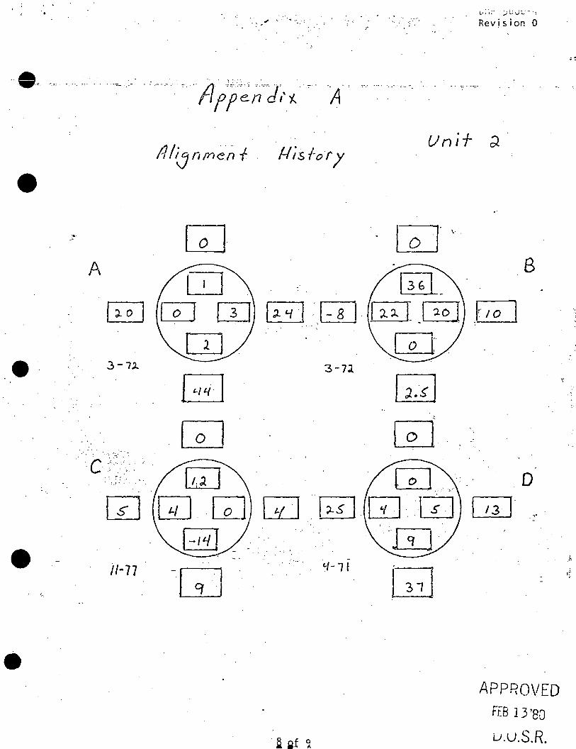
.. ' .
Revision 0
.. -~- --". ·.··· .. , ..... -~ >. . : _.. -.- . c-. _ .. /1' ;;.:·:.~;:; __ _. ____ d... . ... 7'-' ._ • '
· · r1 ff en ,·"' . A :- . ... . - . - . .. . . - . -: - ·-:-:·
•
•
.. ~-
. Uni+ ;l
[QJ [QJ' '· . D
GJ [2§1_ 8
[QJ w ~ --1-8 1. [ii}~ i~ ITJ [~J
3-7l
[;] ~ [Q] ~
. -c·+:>·:.~--- . ·_;-.:. . Gd] GJ. _·:_·
- . . ·"' >. D
w w. GJ w ---~ w ... -w CQJ· ,,. ~ __ - --w-·
.-: . .
-•/-lf [;2J ..
-~.
l__LJ
APPROVED
FEB 13 '80
u.u.S.R.
" .,

... ,. .· . .
..
·,.
•
-· ..
' - . -~-'
-· ' • !> ~
•
A ~
~.[11 w . [QJ
10 - 76
, .·~
. : ... ··
. ·. [ii]
. :~· ', . - .
[fl] [;] [iJ
GJ ~-.__
Dn? ~GLiD-;.; Revision 0
Unif 3
. CE]" '.· ..
0. B
1o1 GbJ _cw . 0· w ··~ . GJ GJ· .
.:~:..; .
.r ',
. OJ• .. . ' .. ;·,· . .. , · . ••·· ... !. ·' .
- . ' .:•.. . D .. ~-
l~sj IT]-~ ,· .. ill
0
APPROVED FEB 13 '80
U.U.S.R.
I \
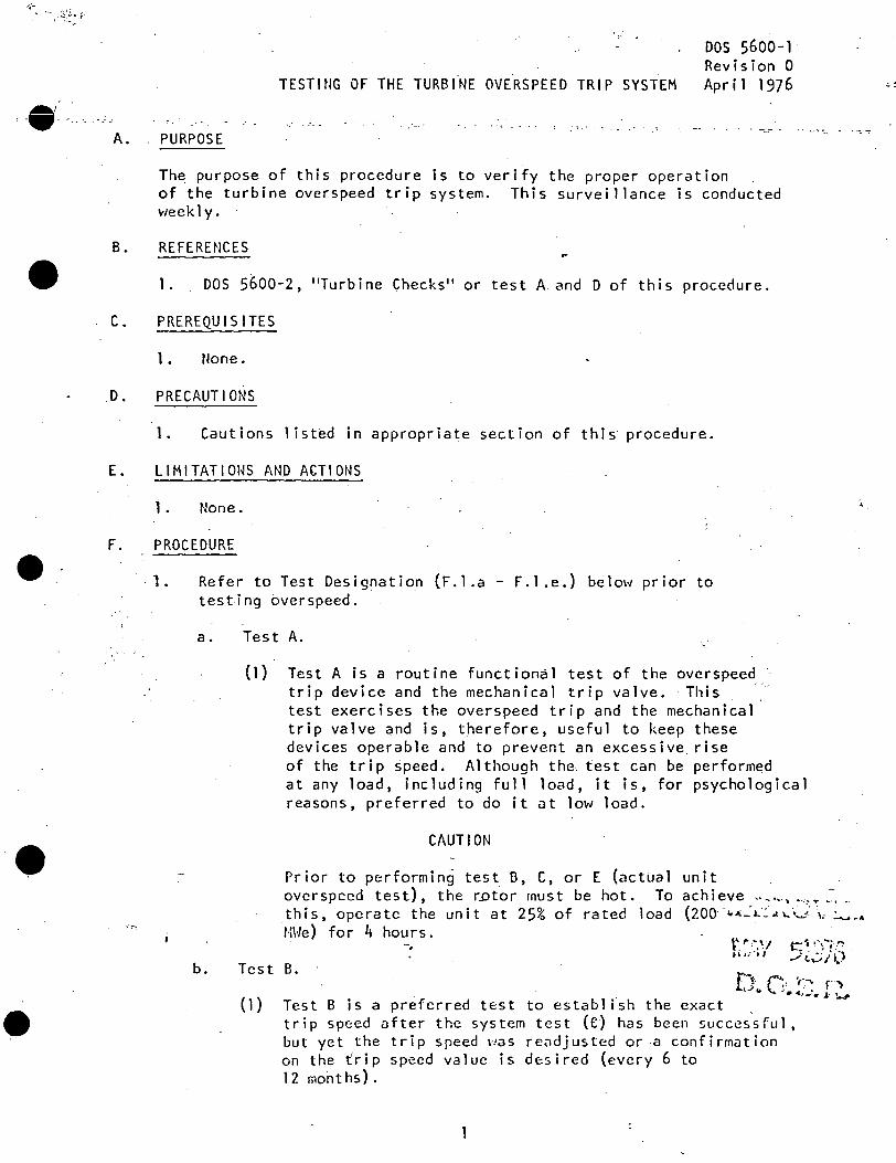
'-··-.-.c,_
•
•
A.
TESTING OF THE TURBINE OVERSPEED TRIP SYSTEM
PURPOSE
DOS 5600-1 Revision 0 Apr i 1 1976
The purpose of this procedure is to verify the proper operation of the turbine overspeed trip system. This surveillance is conducted weekly.
B. REFERENCES
1. DOS 5600-2, "Turbine Checks" or test A and D of this procedure.
C. PREREQUISITES
1. None •
. D. PRECAUTIONS
1. Cautions listed in appropriate section of this procedure.
E. LIMITATIONS AND ACTIONS
1. None.
F. PROCEDURE
'-1. Refer to Test Designation (F.1.a - F.1.e.) belm-J prior to testing overspeed.
a.
b.
Test A.
(1) Test A is a routine functional test of the ovcrspeed trip device and the mechanical trip valve. ·This --test exercises the overspeed trip and the mechanical trip valve and is, therefore, useful to keep these devices operable and to prevent an excessive. ris_e of the trip ~peed. Although the test can be performed at any load, including ful 1 load, it is, for psychological reasons, preferred to do it at low load.
CAUTION
Prior to performing test B, C, or E (actual ovcrspccd test), the rotor must be hot. To this, operate the unit at 25% of rated load MHe) for 4 hours.
unit achieve .............. \ ···-=-."" ..... , ~·
(200 · 1.A:.: 1.·: .l \,, "'"-" ,, .:....... ~ ..
\',. ,.,,, t ~ i~· - , I
~~ ~··\,--;·.'*":-
_; 1...:.: i () Test B. f} f"':, ·,:-. r ~ { 1 )
. . t--'e '-.. .~.~-~. J: ~ Test Bis a preferred test to establish the exact . trip speed after the system test {e) has been succes~ful, but yet the trip speed was readjusted or a confirmation on the ~rip speed value is desired (every 6 to 12 months).
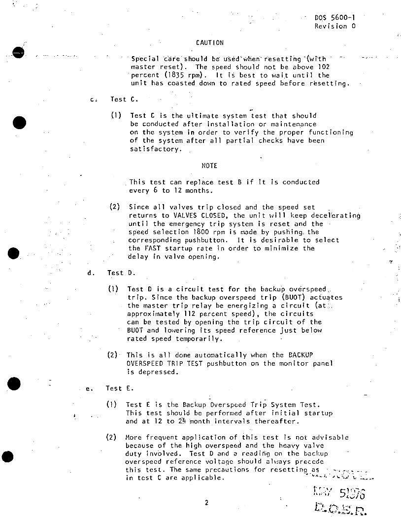
•
e.
••
CAUTION
DO.S 5600-1 Revision 0
·Special ·care.should be u·sed'wlien··resetting -(with master reset). The speed should not be above 102
·percent (1835 rpm). It is best to wai.t until the unit has coasted dO\<Jn to rated speed before resetting.
c. Test C.
(1) Test C i~ the ultimate system test that should be conducted after installation or maintenance on the system in order to verify the proper functioning of the system after all partial checks have been satisfactory.
NOTE
. This test can replace test B if it is conducted every 6 to 12 months.
(2) Since all valves trip closed and the speed set . returns to VALVES CLOSED, the unit will keep decel~rating until the emergency trip system is reset and the speed selection 1800 rpm is made by pushing.; the corresponding pushbutton. It is desirable to select the FAST startup rate in order to minimize the delay in valve opening.
d. Test D.
. e.
(1) Test D is a circuit test for the backup ov~rspeed .. trip. Since the backup overspeed trip (BUOT) actuates the master trip relay be energizing a circuit (at~. approximately 112 percent speed), the circuits can be tested by opening the trip circuit of the BUOT and lowering its speed reference just below rated speed temporarily.
(2) This is all done automatically when the BACKUP OVERSPEED TRIP TEST pushbutton on the monitor panel is depressed .
Test E . -
(1) Test E is the Backup Oversp0ed Trip System Test. This test should be performed after initial startup and at 12 to z·~ month intervals thereafter.
(2) More frequent application of ihis test is not advisable because of the high overspeed and the heavy valve duty inv61ved. Test D and a readi~~ on the backup over speed reference vol tcigc should cih:ays precede this test. The same precautions for resettinq as · - .... ,, -· _ in test Care applicable. -........ _l_· .. ._·.~_,...··\.: :....~--
2
t· f" • ' ' I~ 1i ·i 1' 5
..... - .... ! . ' •.
~,jlb
.. ·~
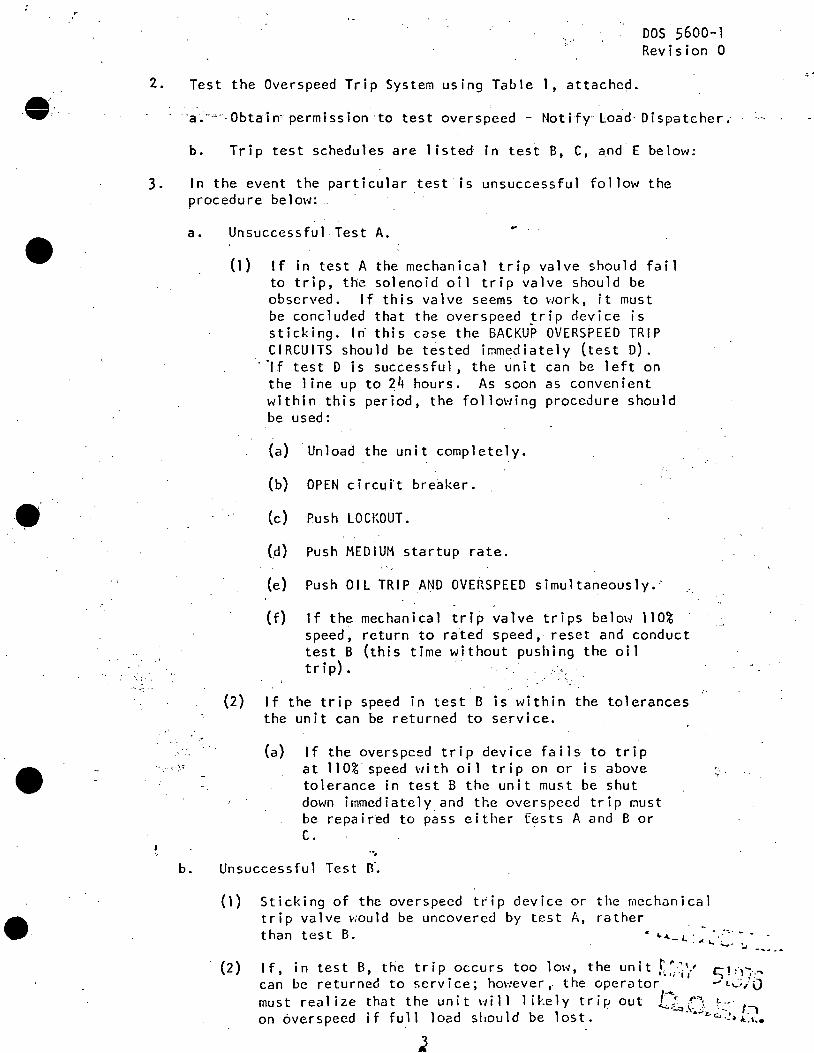
•
-· -_;.
•
2.
·~ ...
Test the Overspeed Trip System using Table 1, attached.
DOS 5600-1 Revision 0
·a.---~· Obta·in~ permission ·to test overspeed - Notify· load· Dispatcher.·
b. Trip test schedules are listed rn tes~ B, C, and E below:
3. In the event the partic~lar test is unsuccessful follow the procedure below: .
a .
b.
Unsuccessful-Test A.
(1) If in test A the mechanical trip valve should fail to trip, the solenoid oil trip valve should be observed. If this valve seems to work, it must be concluded that the overspeed trip device is sticking. lri this case the BACKU~ OVERS~EED TRIP CIRCUITS should be tested immediately (test D) .
. ·1f test D is successful, the unit can be left on the line .up to 24 hours. As soon as convenient within this period, the following procedure should be used:
(a) Unload the unit completely.
(b) OPEN circutt bre~ker.
(c) Push LOCl~OUT.
(d) Push MEDIUM startup rate.
(e) Push OIL TRIP AND OVE~SPEED simultaneously.'
(f)
(2) If the trip speed in test B is within the tolerances the unit can be returned to service.
(a) If the overspced tdp device fails to trip at 110%. speed with oil trip on or is above tolerance in test B the unit must be shut down immediately and the overspecd trip must be repaired to pass either fests A and B or c.
-·. Unsuccessful Test n~
( 1 ) Sticking of the overspecd t~ip device or the mechanical trip valve would be uncovered by test A, rather
~: . .,. .
than test B. .. ~ ... -l. ... ~ ··-·
'->· J ---- ~ ...
(2) If, in test B, the trip occurs too low, the unit r~,-i~·' c;!~)'";·," can be returned to service; hm·1ever ,. the opera tor _, t,_"_;/O must realize that the unit \·till likely trip out L--:• ~'\ i. .. '. t . .__,, \· . . - :1 on 6verspeed if full load should be lost. .,.,.,.,,w.!~.l:i ••
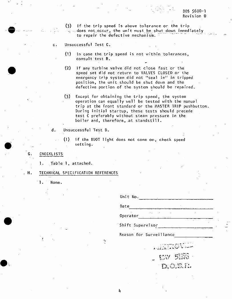
----
•
•
•.
DOS 5600-1 Revision 0
(3) If the trip speed is above tolerance or the trip doe.s not.occur., the unit must be shut do\lm immediately to repair the defective mechanTsm~ -- --- ., __ . __ ,. -- · · ----- ·
c. Unsuccessful Test C.
(1) In case the trip speed is not within tolerances, consult ·test B.
(2) If any turbine valve did not close fast or the speed set did not return to VALVES CLOSED or the emergency trip system did not "seal in" in tripped position, the unit should be shut down and the defective portion of the system should be repaired.
(3) Except for obtaining the trip speed, the system operation can equally well be tested with the manual trip at the front standard or the MASTER TRIP pushbutton. During initial startup, these tests should precede test C preferably without steam pressure in the boiler and, therefore, .at standstill.
d; Unsuccessful Test. D.
( 1) If the BUOT 1 i ght does not come on, check speed setting ..
G. CHECKLISTS
1. Table 1, attached.
. H. TECHNICAL SPECIFICATION REFERENCES
1. None.
Unit No.
Date
Operator --------~---------------------
Shift Supervise_'. --------~-------------
Reason for Surveillance -------·.
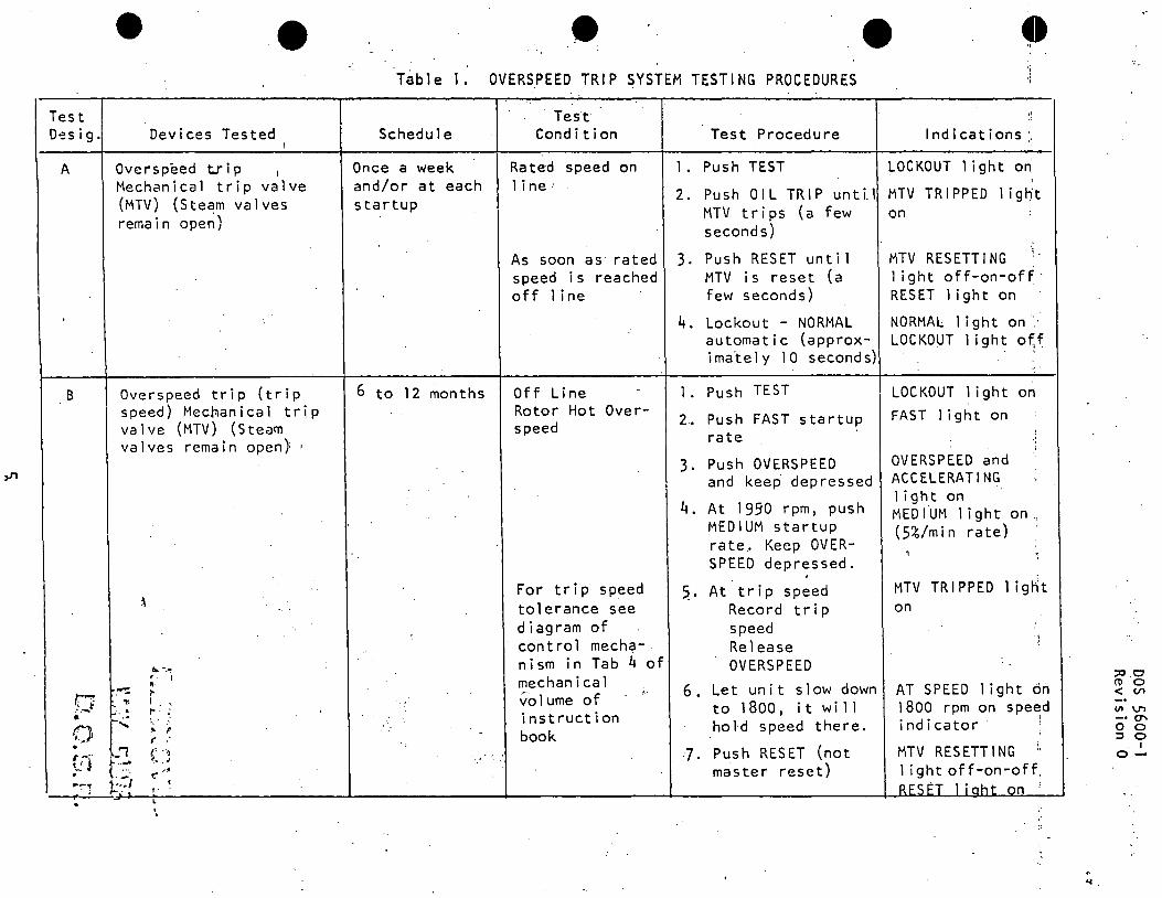
Test D',?S i g.
A
B
/;1 .·.-. • f.') ··~ • r-·· •..: J . ,.-:-1
,.
• Devices Tested
Overs peed t.r i p 1
Mechanical trip valve (MTV) (Steam valves remain ope~)
Overspeed trip (trip speed) Mechanical trip valve (MTV) (Steam va 1 ves remain open} 1
""-~ '. I • ~ I"
"' I ' 1-·· . I"
f; .. : .. " (
( ··~ ~- . , t:' ,·1
~--:1 • . . , . "'"-
•• T~ble 1. OVERSPEEb TRIP SYSTEM TESTING PROCEDURES
Schedule
Once a week and/or at each startup
6 to 12 months
... ..
..
·Test·· Condition
Rated speed on 1 ine ..
As soon as rated speed is reached off 1 i ne
Off Line -
Rotor Hot Over-speed
For trip speed tolerance see diagram of
· control mech9-ni sm in Tab 4 of mechanical volume of instruction book
Test Procedure Indications: ..
1. Push TEST LOCKOUT light on I
2. Push OIL TRIP until MTV TRIPPED light MTV trips (a few on seconds)
3. Push RESET until MTV is reset (a few seconds)
4. Lockout - NORMAL automatic (approx-ima"tely 1 0 seconds)
1. Push TEST
2~ Push FAST startup rate
3. Push OVERSPEED and keep depressed
4. At 1990 rpm, push MEDIUM startup rate .. Keep OVERSPEED depressed.
~· At trip speed Record trip speed Release OVERSPEED
6. Let unit slow down to 1800, it wi 11 hold speed there.
J. Push RESET (not master reset)
MTV RESETTING 1 ight off-on-off· RESET 1 i ght on
NORMAL 1 i ght on ':LOCKOUT 1 ight o~f
LOCKOUT 1 ight on FAST 1 i ght on
OVERSPEED and ACCELERATING 1 i ght on MEDIUM 1 ight on, (5%/min rate)
.. MTV TRIPPED 1 ignt on
AT SPEED 1 ight on 1800 rpm on speed indicator ·:
MTV RESETTING " 1 i ght off-on-off. RESET 1 i aht on ·:
, . ... .
:::0 0 ro o < Vl
VI V"1 -· O' 0 0 ::::J 0
I o-
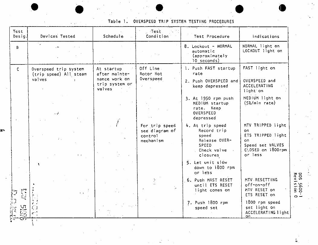
Test Desig.
B
c
..
L~ ;.~
K·-' ~ .. . ~
' -..... . ~·1 ,:;··~·
xr \J1 ,..._,. \.· "l ..:;:,
t~ .. .; 1,,.1 I
•
'
. • 'I'.
Devices Tested
Overspeed trip system (trip speed) All,_ steam valves 1
...
I I
'
• .. "' I I I
~
'I.
r .. J '.-r." .. '
I
• ' ' t
• • Table 1. OVERSPEED TRIP SYSTEM TESTING PROCEDURES
Schedule
At startup a f te·r ma i htenance work on trip system or valves
.f i· I
. ·Test. Condition
Off Line Rotor Hot Overs peed
For .trip speed see diagram of control mechanism
Test Procedure
8. Lockout - NORMAL automatic (approximately 10 seconds)
1. Push FAST startup rate
2. Push OVERSPEED and keep depressed
3. At 1950 rpm push MEDIUM startup rate. Keep OV ERSPEED depressed
4. At trip speed Record trip speed Release OVERSPEED Check valve closures
5. Let unit s 1 ow down to 1800 rpm or 1 e's s
6. Push MAST RESET until ETS RESET 1 ight comes on
?· Push 1800 rpm speed set
Indications
NORMAL 1 ight on LOCKOUT 1 ight on
FAST 1 ight on
OVERSPEED and ACCELERATING 1 i ght on
MEDIUM light on (5%/mi n rate)
MTV TRIPPED 1 ight on ETS TRIPPED 1 ight on Speed set VALVES C~OSED on 1800rpm or 1 ess
MTV RESETTING off-on-off MTV RESET on -
ETS RESET on
1800 rpm speed set 1 ight on ACCELERATING 1 ight on ·
:::00 ,.
ro o < (/) VI \J1 -· O'\ o.o :l 0
I o-
.. ~.
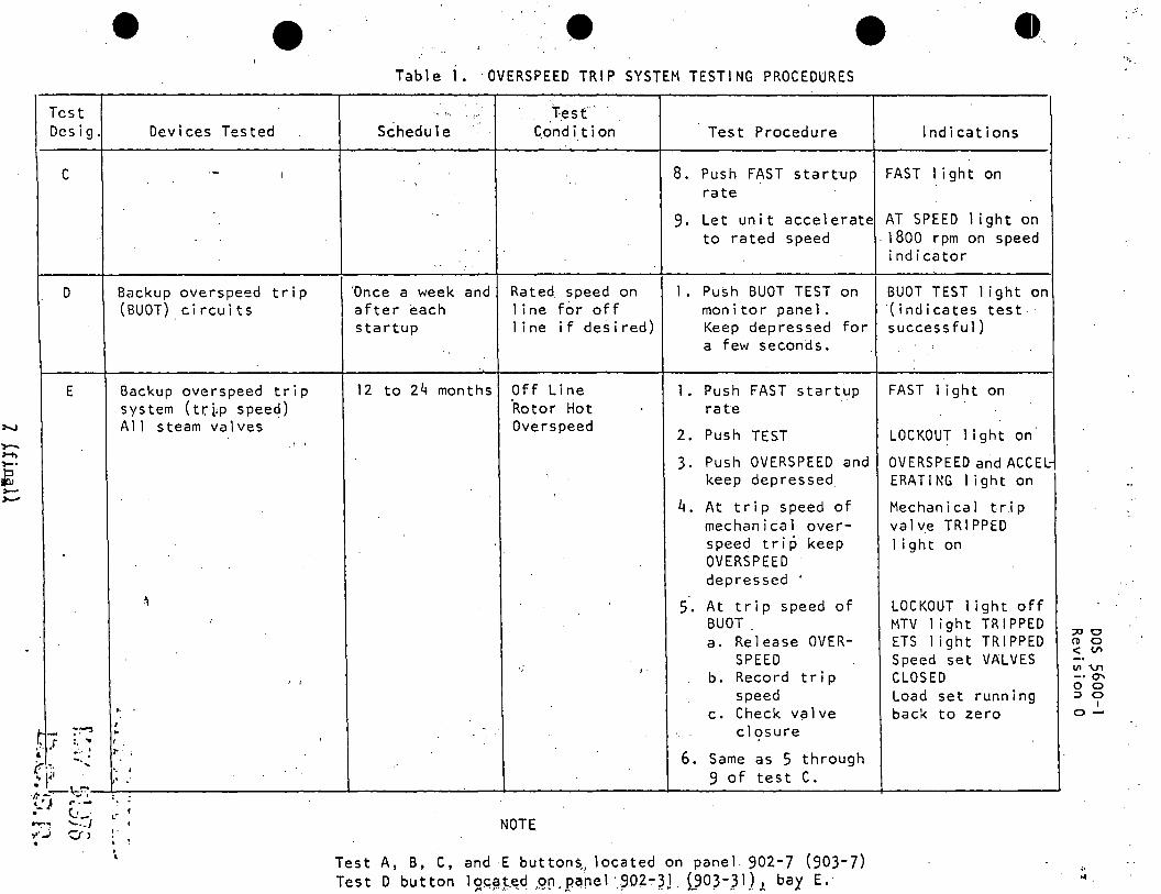
Test Desig.
c
D
E
t - :-:-:i
• Devices Tested
Backup overspeed trip (BUOT) circuits
Backup overspeed trip system (tr~p speed) All ste~rn valves
I I
' I
" , ..
• 9 . Table 1. OVERSPEED TRIP SYSTEM TESTING PROCEDURES
Schedule
'Once a week and after each startup
· T.esf · C.ond it ion
Rated speed on 1 i ne for off 1 ine if desired)
12 to 24 months Off Line ·Rotor Hot Overs peed
.,
Test Procedure
8. Push FAST startup rate
Indications
FAST 1 ight on
9. Let unit accelerate AT SPEED 1 ight on to rated speed . 1800 rpm on speed
1. Push BUOT TEST on rnon i tor pane 1 • Keep depressed for a few seconds.
1. Push FAST startup rate
2. Push TEST
3. Push OVERSPEED and keep depressed
4. At trip speed of mechanical overspeed trip keep OVERS PEED depressed ·
S. At trip speed of BUOT a. Release OVER
SPEED b. Record trip
speed c. Check valve
closure
indicator
BUOT TEST 1 ight on (indicates test. successful)
FAST 1 ight on
LOCKOUT light on
OVERSPEED and ACCEl: ERATING 1 ight on
Mechanical trip valve TRIPPED 1 ight on
LOCKOUT 1 ight off MTV 1 ight TRIPPED ETS 1 ight TRIPPED Speed set VALVES CLOSED Load set running back to zero
' r .... ~.:, ::~ 6. Sarne as 5 through .. l'' · :: .' 9 o f t e s t C •
,.. :
. ;----\.::~~.1.--~~~~~~~~~~~-'-~~~~~--~----~~~~~~~~--~~~~~~~~~~-+~~~~~~~~--' t.:} r . .-• c_. _. ..... ~ ........ / .,.:.; Cl> .
.- . .. '
I NOTE
Test A, B, C, and E buttons .. located on panel 902-7 (903-7) Test D button lS?~~~.E~c! ,Q!1.pt'lnel ·~_OZ-~}. l90)-,3l) J. bay E.
:::00 (1) 0 < Vl
Ill '\T1 -· O' 0 0 :J 0
I o-
,. ...
'> ...
•
•
Revision 6
.Procedure No.
DRESDEN STATION PROCEDURE ROUTING (Control Rod Withdrawal)
Procedure Title ~·-~~P~. ~~---~-··~'-Y~G_,~~~~~~-~~o~~-/_r~(~u~{~~-~--~~~~~~~~-~-c~.{-~~S Date c/C /78 I l
This procedure involves control rod withdrawal and, in accordance with OAP 9-2, is subject to the following approvals prior ~o On Site Review.
Approved:
?' ~L~:i::;;~·r
••I '
·, -;..·.
---~~
'.
FORM 9-2C
8
Assistant Superintendent
f.IPl\1 c,·:-·.,·(I ,•1~~ }_ .· IV
o.o.s.R~
f .
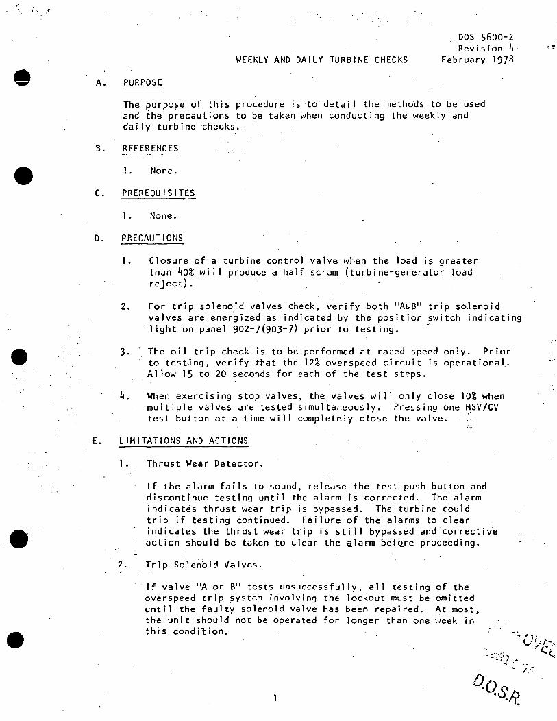
.5: I I.· .•'
•
A.
WEEKLY AND DAILY TURBINE CHECKS
PURPOSE
DOS 5600-2. Revision 4.
February 1978
The purpo~e of this procedure is to detail the methdds to be used and the precautions to be taken when conducting the weekly and daily turbine ~hecks. ·
B~ REFERENCES
1. None.
C. PREREQUISITES
1. None.
D. PRECAUTIONS
1. Closure of a turbine control valve when the load is greater than 40% will produce a half scram (turbine-generator load reject).
2. For trip solenoid valves check, verify both "A&B" trip soJienoid valves are energized as indicated by the position ywitch indicatin~ light on panel 902-7(903-7) prior to testing.
3. · The oil trip check is to be performed at rated speed only. Prior to testing, verify that the 12% overspeed circuit is operational .
. Al low 15 to 20 seconds for each of the test steps.
4. When exercising ~top valves, the valves wi 11 only close 10% when multiple valves ar~ tested simultaneously. Pressing one MSV/CV test button at a time will completely close the valve.
E. LIMITATIONS AND ACTIONS
2. - ~~·
Thrust Wear Detector.
If the alarm fails to sound, release the test push button and discontinue testing until the alarm is corrected. The alarm indicates thrust wear trip is bypas~ed. The turbine could trip if testing continued. Failure of the alarms to clear indicates the thrust wear trip is still bypassed and correcti~e action should be taken to clear the ~larm b~fQre proceeding.
Trip Solenoid Valves.
.·.-:
t:,·
· 1f valve "A or B" tests unsuccessfully, all testing of the overspeed trip system involving the lockout must be omitted until the faulty solenoid valve has been repaired. At most, the unit should not be operated for longer than one week in this condition. """'':'. -.,, ....
v''./,--, -:' ;~ _: '~,
•
J ' ~ •• ·' - •
•
F.
DOS 5600-2 Revision 4 ·~
3. Turbine Shaft Voltage.
a. If a reading of greater than one volt occurs, the grounding brush is not making proper contact and mairitenance may be required. If a reading of 10 volts occurs, Maintenance should be contacted and corrective ~ction taken.
4. If tests are incomplete, notify Operating ~ngineer and initiate repairs •
PROCEDURE
The procedure for each group of tests should be adhered to as outlined on the check off sheet for each te~t. Note the cautions where applicable.
G. CHECKLISTS
1. Attached.
H. TECHNICAL SPECIFICATION REFERENCES
1. None •.
.·.~
D.o.s.R.
2
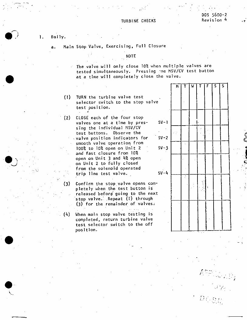
.:-·-.,,
1.
TURBINE CHECKS
Dai 1 y.
. ' '
DOS 5600-2 Revision 4
a. Main Stop Valve, Exercising, Fu11 Closure
NOTE
The valve .will only close 10% when multiple valves are tested simultaneously. Pressing ~ne MSV/CV test button
• at a time will completely close the valve.
..... ,.,.
• --· \ ·-..
(1) TURN the turbine valve test selector switch to the stop valve test position.
~
(2) CLOSE eqch of the four stop valves one at a time by pressing the individual t\SV/CV test buttons. Observe the
, valve position indicators for smooth valve operatic~ from 100% to 10% open on Unit 2 and fast closure from 10% open on Unit 3 and 4% open on Unit 2 to fully closed from the solenoid operated trip line test valve._
(3) Confirm the stop valve opens completely when the test button is released befor~ going to the next
'.stop valve.- Repeat (1") through (3) for the remainder of valves;
(4) When main stop valve testing is completed, return turbine valve test selector switch to the off po~ition.
M T
SV-1
SV-2
SV-3
w T F s s
.
-
,-, .. j
I
~
.r ~- -- . r· . .... • .. • ...... J
. ·-. J
; .. ,/
- I
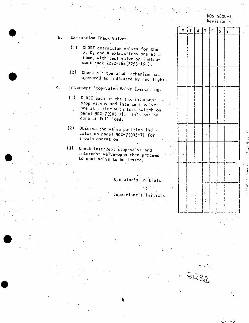
•
•
b. Extraction Check Valves.
(1) CLOSE extraction valves for the D, C, and B extractions one at a time, with test valve on instrument rack 2252-i6E(2253-J6E).
{2) Check air-operated mechanism has operated as indicated by red light.
c. Intercept Stop-Valve Valve Exercising.
{l) CLOSE each of the six intercept stop valves and intercept valves
· one at a time with test switch on panel 902-7(903-7). Th)s can be done at full load.
(2) Observe the valve position indicator ~n panel 902-7(903-7) for smooth operation.
(3) Check intercept stop-valve and interc~pt valve-open then proceed to next valve to be tested.
.Operator's lni~ials ·-.· '.
Supervisor's Initials
.
---M T w - -
~· ..__ ,_
I---
--- ·-- -
I -I
L ........ L
I I
T
DOS·5600-2 Revision 4
F. s s
(
-- --- ·--
'
---l I 1
I
I I !
;
' ;. ' {. I
I I
' I : I
.
l I J
I ! ! I --L--. __J
-· .. ·
(
. .. ,, .'i"/ . ,. . ~:
~.
. (
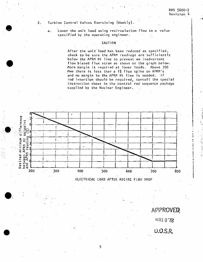
•
:.e-·
DOS 5600-2 Revision 4
2. Turbine Control Valves Exercising (Weekly).
Q)·
0 c +' Q) c L ·Q) 0
. ...... c,.:...
a. Lower the unit load using recirculation flow to a value specified by the operating engineer.
CAUTION
After the unit. load has been reduced as .specified, check to· be sure the APRM readings are sufficiently below the APRM Hi line to prevent an inadvertent flow·biased flux scram as shown on the gr~ph below. More margin is required at lower loads. Above 700 Mwe th~re is less than a 1% flux spike on APRM's and no margin to the APRM Hi 1 ine is needed. If rod insertion should be required 1 consult the special instruction sheet in the control rod sequence package supplied by the Nuclear Engineer.
...... ~cN' ·-----~----'---..... ~----<f------'--~~----,r-----1----t---+----+ . .·- .. ar---. -0 .. 111
rnu------~_,_---=----+--'=""t:i~----+---:......;----t-----1-----1----ir-----i E~c ::J :Z:·-E . ·"O ___ .:._ __ _;.----t---i---i,--------';'=----!.-:----i~--+----~--+--~
. ·- ~(lJ c a:: Q) ·- a..~Li-'--'---'----~---'----+~--+---+-----,-~~""""':--T----1--__.;:----1-----i E <C.
-o·c~lr·---,,----r-----:-------:-----1----i,------t------.~--="""""~~--+----+----i Q) Q)a.. . I,
~ Q)<(CJ----"'----;----.;._--.i_--+-~-+--~+-~-+----+--_:::-.... ____ ~-----; ·- 3 &I') "-'-0 - ! Q) Q) c
0 .0 (lJ
200 300 400 500 600 700 Boo
EL EC TR I CAL LOAD AFTER REC I RC FLO\/ DROP
· u.O.S.R.
5
•,
'.. }
r I
l·
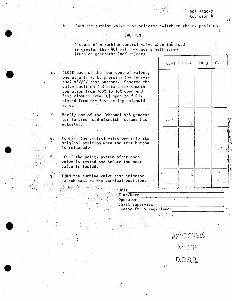
•
. ·-. •'
_,• .. _. ~
•
·:. -.,,
DOS 5600-2 Revision 4
b. TURN the turbine valve test selector switch to the cv· position.,
CAUTION
Closure of a turbine control valve when the load is greater than 40% will produce a half scram (turbine generator load reject).
i I 1 CV-1 f CV-2 !
c. CLOSE each·of the four control valves, one at a time, by pressing the individual MSV/CV test buttons. Observe the valve position indicators for smooth operation from 100% to 10% open and fast closure from 10% open to fully closed from the fast acting solenoid valve.
d. Verify one of the "channe I A/B generator tµrbine load mismatch" scrams has actuated.
e.
I
..
I
I I I I I I '
I '(.
I
(
i-::;r:v:-
. '
I I
I I f
i \ ,.
' Confirm ·the control valve opens· to its ~rigi_nal position when the test button is' released.
I !
!~ i
~,
! -- - •·.:
(. RESET the safety system after each valve f~ tested and before the next va.lve is .tested.
g. ·. njRN ~he' turbine valve test selector ~witch back t6 the vertical position.
. " : ·· · Uni. t - ,.:: .. · . ..:: . .::...-- ..... · l
I
I ... !
•C .. · ... .. .
-· ---------------------
. ~.Ji me/Date _____ ~-------------Operator
------------------~ Shift Supervisor ~-=--------------Re as on for S~rveillance ------------
·:,,,
!""="'f• . , ..... '· ''-
D.O.S.R ..
6
~.
! 'h i
)
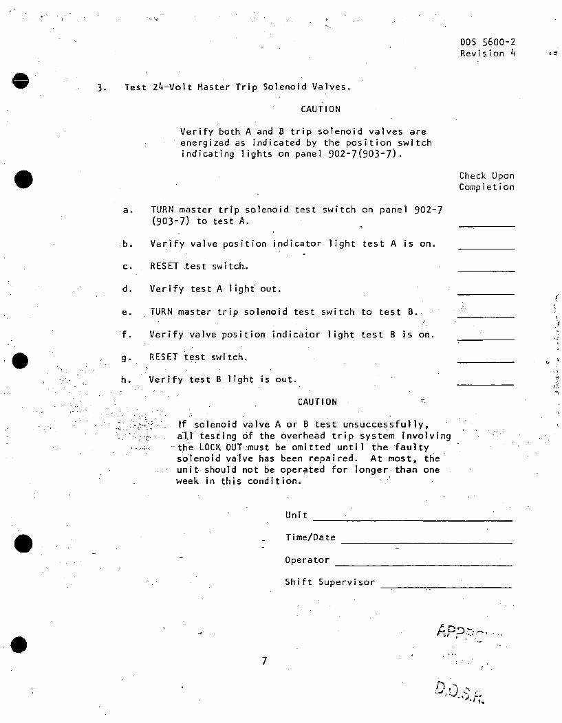
·O 3.
•
I,.
~ . '/ · ..
•
'','::...;
Test 24-Volt Master Trip Solenoid Valves.
a.
. b.
c.
d.
e.
f.
g.
CAUTION
Verify both A and B trip solenoid valves are energized as indicated by the position switch indicating lights on panel 902-7(903-7) .
TURN master trip solenoid test switch on panel 902-7 (903-7) to test A.
Verify valve position indicator light test A is on •
RESET %est switch.
Verify test A light out.
TURN master trip solenoid test switch to test B.
Verify valve position indicator light test B is on.
RESET test switch.
h .. Verify iest Blight is out.
., . ~ . . . . ·~··· . . · ....
CAUTION
If solenoid valve A or B test uns~ccessfu11y, a1l testing cif the overhead trip system involving
··the LOCK OULmust be omitted unti 1 the ·faulty solenoid val~e has been repaired. At most, the· unit should not be operated for longer than one week in this condition.
Unit
Shift Supervisor
7
DOS 5600-2 Revision 4 ·~
Check Upon Completion
., ..;
'j
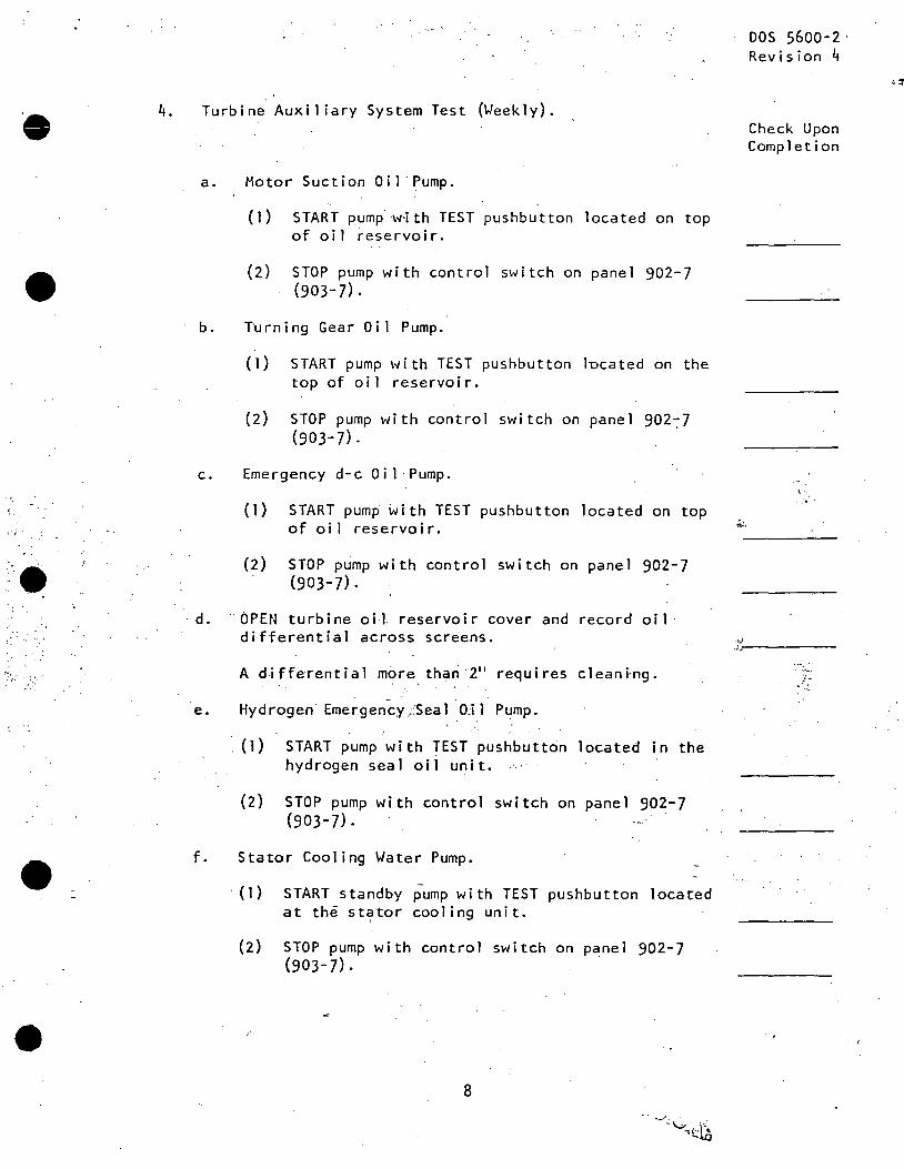
4.
•
>._
•
Turbine Auxiliary System Test (Weekly).
a. Motor Suction Oil Pump.
{1) START pump w·ith TEST pushbutton located on top of oil ~eservoir.
{2) STOP pump with control switch on panel 902-7 (903-7).
b. Turning Gear Oi 1 Pump.
( 1) START pump \'II i th TEST pushbutton lucated on the top of oil reservoir.
(2) STOP pump with control switch on panel 902~7 (903-7).
c. Emergency d-c Oil ·Pump.
. d.
(1) START pump with TEST pushbutton located on top of oil reservoir.
(2) STOP pump with control switch on panel 902-7 (903-7).
OPEN turbine oil reservoir cover and record oil· differential across screens.
A differential more th~n 211 requires cleani·ng.
e. Hydrogen· EmergencyjSeal OJl Pump.
·. (1) START pump with TEST pushbutton located in the hydrogen seal oil unit.
(2) STOP pump with control switch on panel 902-7 (903-7).
f. Stator Cooling Water Pump •
· {1) START standby pump with TEST pushbutton located at th~ stator cooling unit.
(2) STOP pump with control switch on panel 902-7 {903-7).
8
~.
DOS 5600-2· Revision 4
Check Upon Completion
' '~ .
.~:-'-----. ..., ..
. I
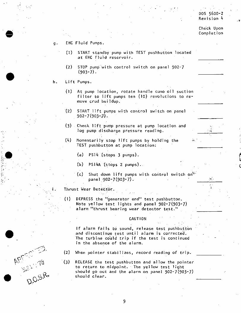
·e g.
• h.
•·'·
) ... . ~··,·· ty . . ~ .. ' .
'.:\:
•
EHC Fluid Pumps.
(I) START standby· pump with TEST pushbutton located at EHC fluld reservoir.
(2) STOP pump with control switch on panel 902-7 (903-7) .
Lift Pumps.
(I) At pump location, rotate handle cuno oil suction filter to lift pumps ten (10) revolutions to remove crud buildup.
(2) START lift pumps with control switch on panel 902-7 (903-;7.) __
(3) Check lift pump pressure at pump location and log pump discharge pressure reading.
(4) Momentarily stop lift pumps by holding the ·~·'. TEST pushbutton at pump location:
(a) PS14 {stops 3 pumps) •
(b) PS14A'{st~ps 2 pumps) .
(c) Shut down lift pumps with control switch on~:. panel :-90.2-7 (903-7).
Thrust Wear Detec~or.
( 1) DEPRESS the '"generator end" test pushbutton. Note yellow test 1 ights and pane·! 902-7(903-7) alarm "thrust bearing wear detector test. 11
CAUTION
If alarm fails t6 sound, release test pushbut~bn and discontinue test until alarm .is correcte~. The turbine could trip if the test is continued in the absence of the alarm.
(2) When pointer stabilizes, record reading of trip.
· (3) RELEASE the test pushbutton and ~llow the pointer to return to midpoint. The yellow test light should go out and the alarm on panel 902-7(903-7) should clear.
9
DOS 5600-2 Revision 4
Che.ck Upon Completion
... .·;.,,
·~~· .. ·
(
•
~ .. '
•
,• . -~.. ..J• • ~. .;- •
DOS 5600-2 Revision, 4
(4) DEPRESS the "turbine end"- test pushbutton. Note the yellow test lights and alarm on panel 902-7 (903-7). Obser.ve caution as above.
(S) When p61nter stabilizes, record reading of trip.
(6) RELEASE the test pushbutton and allow the pointer to return to midpoint. The yellow test light should go out and the alarm on panel 902-7(903-7) should clear.
NOTE
'
Che.ck Upon Completion
(a) The pointer should move at about 1 mil per second.
(b) The trip readings should be 30-35 mils. j. Twelve Percent Overspeed Circuit.
. k.
m .
(1) DEPRESS TEST switch on panel 902-31 (903-31) in E Bay.
{2) Ver·ify that TEST 1 ight is on.
Power Load Unbalance Circuit - When Load is Greater than 40% of Rated.
(1)' DEPRESS TEST switch on panel 902-11 (903-31) in E Bay.
(2) Verify that TEST light is on.
Backup Speed Circuit.
(1) DEPRESS TEST switch on panel 902-31(903-31) in E Bay.
(2) Verify that TEST light is on.
Oil Trip Check.
CAUTION
This check is to be performed at rated speed only. Prior to this check, verify that 12% overspeed circuit is operational. Al low 15 to 20 seconds for each of the steps listed below.
10
~ l l
' ')
..
•
·-
. ~. '
.·. ;_: .... :
(l} DEPRESS TEST switch on panel 902-7(903-7).
(2) Verify_that yello~ LOCK OUT light is. on . . •.
(3) DEPRESS OIL TRIP switch .
(4) Verify that green TRIP light is on.
(5) DEPRESS RESET switch.
(6)
Hold for approximately 15 seconds until YELLOW resetting light comes on, reset light comes on, and lockout returns to normal.
NOTE
Turbine trip will result if lockout clears before reset occurs.
·• ·.
Verify t~at red RESET ·light is' on and the YELLOW· LOCK OUT light is cleared •
DOS 5600-2 Revision 4
Check Upon Completion
·shift Supervisor ---------~---~~---------~-
.. ... _.,
Reason For Surveillance
5 •. Turbine ·shaft Voltage (Weekly).:,.
Using the instrument on th~ ~outh side of the turbln~ on the shield wall, record the voltage reading on the t~rbine shaft.
Voltage Reading ---~---------------------------~
.NO·TE
•If a reading of greater than volt occurs, the grounding brush is not making proper contact and maintenance may be required. If a reading of 10 volts occurs, Maintenance should be contacted and corrective action taken.
Unit
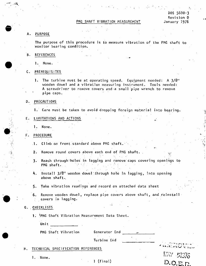
.. • ..:JI .'4.
.....
•
. ·,.
• ;;+·
·9.; "
:.;.
~.
A.
B .
c.
PMG SHAFT VIBRATION MEASUREMENT
DOS 5600-3 Revision 0
January 1976
PURPOSE
The purpose of this procedure is to measure vibration of the PMG shaft to monitor bearing condition.
REFERENCES
1. None.
PREREQUISITES
1. The turbine must be at operating speed. EquJpment needed: A 3/8 11
wooden do\'1el and a vibration measuring instrument. Tools needed: A screwdriver to remove covers and·a small ·pipe wrench to remove pipe caps.
D. PRECAUTIONS
1. Care must be taken to avoid dropping foreign ma.terial into b€:'..~·ring.
E. LIMITATIONS AND ACTIONS
1. None •
F.. PROCEDURE
). Climb on front standard above PMG shaft.· :.t<':
2~ Remove round covets above each end of PMG shaft.
3. Reach through':holes· in laggiT!.g and remove·caps covering openings to PMG shaft. · ·
4. Install 3/811 wooden dm-1el ·.through hole in lagging, into opening above shaft.,
5. Take vibration readings and record on attached data sheet
6. Remove wooden dowel, replace pipe covers above shaft, and .r~install covers in lagging.
G .. CHECKLISTS
1. 1,PMG -Shaft Vibration Measurement Data Sheet.
Unit -------PMG Shaft Vibration Generator End ---------
Turbine End
H. TECHNICAL SPECIFICATION REFERENCES r ,.,.,, r-i,,- ...
•· ·•· .... I· JI '"' I I . -:_) l .J 0 1 •. None.
l ( f i na 1) D.o ~- ,..., • ,.. ... .1.1. ..
"'· ·~ . \
•
' '.
,, 1,··,
·' "
•
:~ ·.
·,.-'
·\ r.
UNIT 2/3 TURBINE THRUST BEARING WEAR DETECTOR MANUAL TEST AND
ADJUSTMENT PROCEDURE
· DOS 5.600-4 -Revision 3 June· l980 ,...,.
A. PURPOSE
The purpose of this procedure is to provide instructions for adjusting the.Thrust Bearing Wear Detecto~ with the turbine on system.· The procedure can also be used as a manual test by.following Steps 2.a., b., c. and d. if the remote test feature in the Control Room is inoperable .
B. REFERENCES
c.
GEK Manual 17917B.
PREREQUISITES
·. l. Permission from Operating Engineer.
2. Notify Shift.'~En,gineer on duty 1'/ho is to get approval from Load Di spa.tcher.
3. Establish communications with Control Room and keep open during tests.
- ~-
D. PRECAUTIONS ..
1. If r:Janual test or local adjustment of the Thrust Bearing Wear ~tector is needed, contact Radiation Depa.r~tment for dose rate and proper clothing requirements. · ·
2. If adjustments aTe made to the Thrust Bearing Hear:;. ~ Detector, the ·turbine trip circuit will be locked
. - :"~·"out for appro,x.imately 15 seconds after the Test .-,;·: · Selecto.r·Switch,,js placed back to the NORMAL position ..
• • ~ i I
~_ .... ,.. lliring'.-.this t'j.me:;' personnel in the Control· Room and at the Thrust Bearing Wear Detector must be observant of any abnormal condition such as the trip light coming on ... If a condition arises which could trip the turbine, immediately return the Test Selector Switch to the TEST position to lock out turbine trip and then investigate ..
E . LIMITATIONS AND ACTIONS
None.
1 of 4
APPRO\/ED JUM l 3'20
. o.o.s.R.
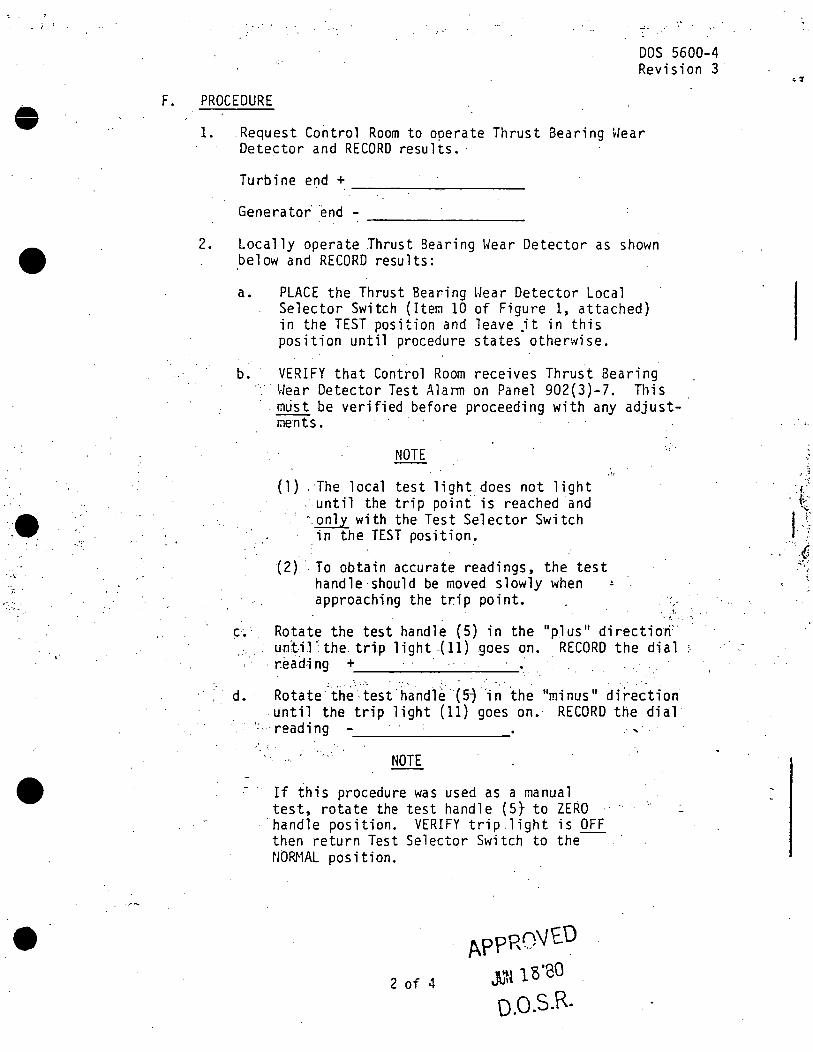
.. ,:
F.
•
---: ~ \'
. ,.
•
,.·
DOS 5600-4 Revision 3
PROCEDURE
1. Request Control Room to operate Thrust Bearing Wear Detector and RECORD results.·
Generator· end -~~~~~~~~-
2. Locally operate Thrust Searing Wear Detector as shown below and RECORD results:
a. PLACE the.Thrust Bearing \·/ear Detector Local Selector Switch (Item 10 of Figure 1, attached) in the TEST position and leave jt in this position until procedure states otherwise.
b. VERIFY that Control Room receives Thrust Bearing ·.·· \·Jear Detector Test Alann on Panel 902(3)-7. This
C.' ·, . . .
· . m'i.ist be verified before proceeding with any adjustments.
NOTE
{l). The local test light does not light · until the trip point is reached and " . ..Q.!!.}_y with the Test Selector Switch
in the TEST position.
(2) '.To obtain accurate readings, the test handle should be moved slowly when approaching the trip point.
··:.
, . ~ .
··t. '•, •,
.:.· .· -
Rotate the test handle (5) in the 11 plus 11 direction' unt-il ·the. trip light .(11) goes on. RECORD the dial
' . reading + ' '
d. Rotate.-the--test h·a.ndl~··(57 ·;~"th~ "minus" dire~tion' -until the trip light (11) goes on.· RECORD the dial
· · ·: ... reading .· ... ;',,:.
NOTE
If this procedure was used as a manual test, rotate the test handle (5} to ZERO
·handle position. VERIFY trip light is OFF then return Test Selector Switch to the NORMAL position.
2 of 4
APPROVED Ju1~ 18'80
0.o.s.R.
• :r
•' ;
·. i.:' . f,.."
I ·r· . '
":.6 .t,!I: . ;
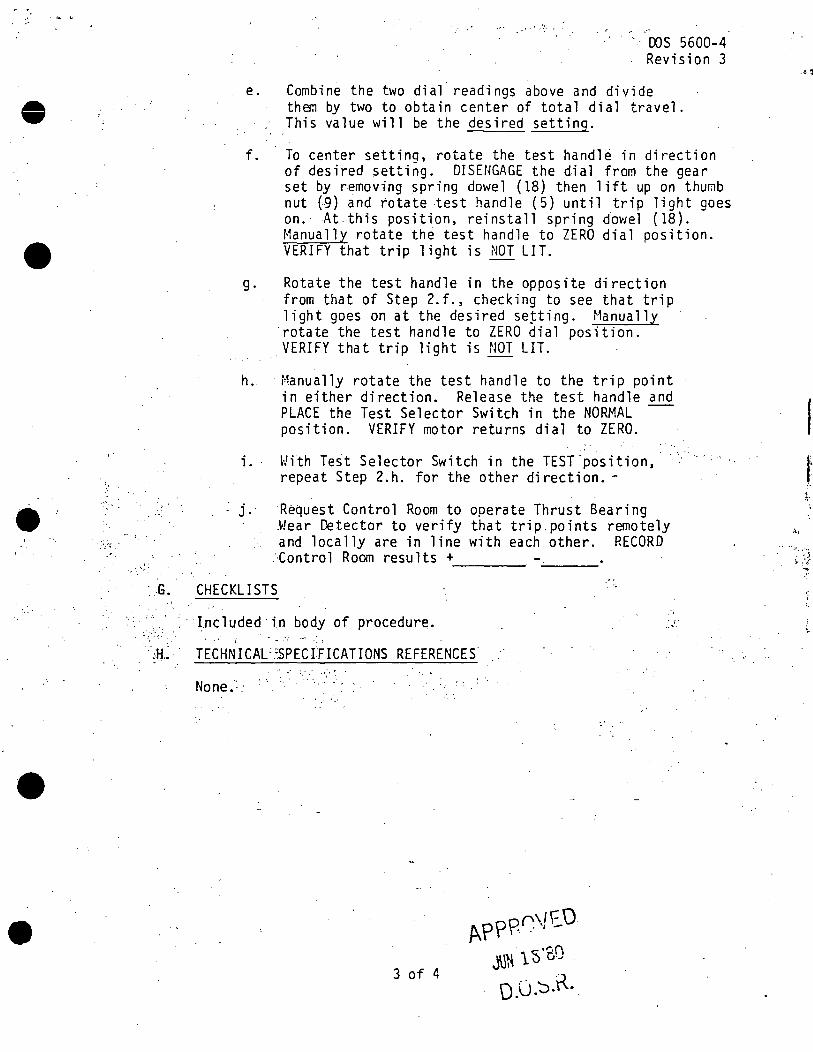
•
.,•·
. ~ ~ .
•
•,.',:
1 '-~-
-. oos 5600-4 Revision 3
e. Combine the two dial readings above and divide them by two to obtain center of total dial travel. This value will be the desired setting.
f. To center settinq, rotate the test handle in direction of desired setting. DISENGAGE the dial from the gear set by removing spring dowel ( 18) then lift up on thuf;lb nut (9) and rotate test handle (5) until trip light goes on.· At .this position, reinstall spring dowel (18). Manually rotate th~ test handle to ZERO dial position . VERIFY that trip light is NOT LIT.
g. Rotate the test handle in the opposite direction from that of Step 2.f., checking to see that trip light goes on at the desired seiting. Manually rotate the test handle to ZERO dial position. VERIFY that trip light is NOT LIT.
h. ·Manually rotate the test handle to the trip point in either direction. Release the test handle and PLACE the Test Selector Switch in the NORMAL position. VERIFY motor returns dial to ZERO.
i. With Te~t Selector Switch in the TEST'position, repeat Step 2.h. for the other direction. -
j. R~quest Control Room to operate Thrust Bearing .Hear Detector to verify that trip.points remotely and locally are in line with each other. RECORD
..Contra l Room results + ----- G. CHECKLISTS
Included in body of procedure. .. ,/. ' .. :, . ~. . .
' ~ . - ' . - ·: ... . ~a .. TECHNICAL'3PECfFICATIONS REFERENCES
None.· -'' '-·
3 of 4
:.,
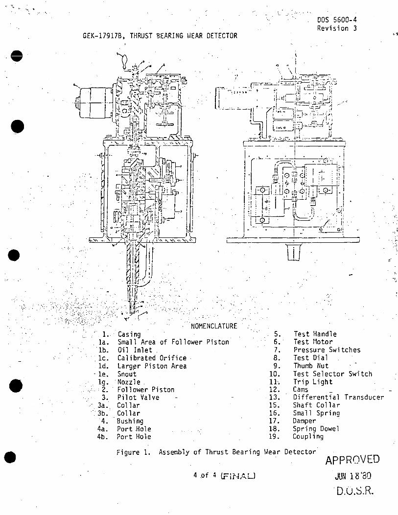
.•.'
• ' .
•
GEK~l7917B, THRUST BEARING WEAR DETECTOR
. 1. . la.
'lb. le. ld.
Casing Small Area of Follower Piston Oil Inlet Calibrated Orifice Larg~r Piston Area
- le. Snout lg. ·Nozzle .
'-·'· 2. Follower Piston 3. Pilot Valve
· 3a. Collar 3b. Collar 4. · Sushi ng
4a. Port Hole 4b. Port Hole
.. . . ; .. ·.' . '
5. 6 •. 7. 8. 9.
10. 11-. 12. 13. 15. 16. 17. UL 19.
DOS 5600-4 Revision 3
Test Handle Test Motor Pressure Switches Test Dial Thumb Nut Test Selector Switch Trip Light Cams _ Differential Transducer Shaft Collar Small Spring Damper Spring Dowel Coupling
Figure 1. Assembly of Thrust Bearing \~ear Detector APPROVED
JUN 18 '80 4 .of 4 t.rir·L~L)
. 0.0.S.R.
J
"' ·. :~
·,
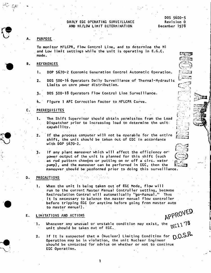
A.
B.
c.
DAILY EGC OPERATING SURVEILLANCE AND HI/LOW LIMIT DETERMINATION
DOS 5600.;.5 Revis ion 0
December 1978
PURPOSE
To monitor HFLCPR, Flow Control Line, and to determine the Hi and low 1 imit settings while the unit is operating in E.G.C. mode.
REFERENCES
1. DOP 5670-2 Economic Generation Control Automatic Operation.
2. DOS 500-16 Operators Daily Surveillance of Thermal~Hydraulic Limits on core power distribution.
3. DOS 500-18 Operators Flow Control Line Surveillance.
4. · Figure 1 AFC Correction Factor to MFLCPR Curve.
PREREQUISITES
1 •
2.
The Shift Supervisor should obtain permission from the Load Dispatcher prior to increasing load to determine the unit~ capability.
If the process computer will not be operable for the entire shift, the unit should be taken out of EGC in accordance with DOP 5670-2.
r· '··· •... - . .i
I~ •• : • • . • • ;
-· .. ~ _· .
{.: -- : - .....
3. c~:·::g
If any plant maneuver which will affect the efficiency or" ·--·· power output of the ·un.i t is p 1 anned for this shift (such c~~s) as rod pattern changes ·,or putting on or off a c ire. water . :;;:.i~
. pump), and the maneuver can be .perfor111ed in EGC, then the l2/:S~ maneuver should be:_pe.li;f.ormed prior to doing this surveillance.
O. PRECAUTIONS
1. When· the unit is being taken out of EGC Mode, flow will run to the current Master Manual Controller setting, because
·Recirculation Control will automatically "go-Manual." Thus It ts necessary to balance the.master manual flow controller before tripping EGC (or anytime before going from master auto to master manual).·
E. LIMITATIONS ANO ACTIONS f>.\>\>R0\J£.O · 1. Whenever any unusua 1 or uns tab 1 e condition may exist, the nee,\\ '18 l
unit should be taken out of EGC.. vL
2. If tt is suspected that a (Nuclear) Limiting Condition for Q.Q .. S.ft.. Operation may be in violation, th~ unit Nuclear Engineer _should be contacted for advice on whether or not to continue EGC Operation.
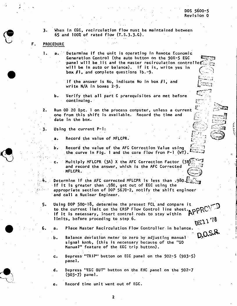
F.
•
•
.. ·
DOS 5600-5 Revision 0
3. When In EGC, recirculation flow must be maintained between 65 and 100% of rated flow (T.S.3.3.G).
PROCEDURE
1 •
2.
3.
a •.
b.
Determine If the unit is operating in Remote Economic Generation Control (the auto button on the 90X-5 EGC -~
. . -- ~ ·panel will be_ lit and the master recirculation controllet:~~::~-:i will be in auto or balance). If it is, write yes in (· ·· . .:·'\ box #1, and complete questions lb.-9. ;:.·.--- '·l
If the answer is No, indicate No in box #1, and write N/A in boxes 2-9.
Verify that all part C prerequisites are met before continuing. ·
Run OD 20 Opt. 1 on the process computer, unless a one from this shift Is available. Record the time date In the box.
Using the c~rrent P-1:
a.
·b •
c.
Record the value of HFLCPR.
Record the value of the AFC . the curve In Fig. 1 and the
Multiply HFLCPR (3A} X and record the answer~
· HFLCPR •
the AFC Correction Factor (3s[!.;)~J which is the AFC Corrected ·::,.:~<3 . . . "'. e-~~
', .. 4 •. . Determine If the AFC corrected H.FLCPR is· less than .980.E.1.~~ ·If it is greater than .980, get out of EGC using the appropriate section of DOP 5670-2, notify the· shift engineer
·and call a Nuclear Engineer. i. ".. .. - ~' •:
5.
6.
Using DOP 500-18, d~termine the present FCL and compare it ,,~:) to the current 1 imit on the CRSP Flow Control 1 ine sheet.l\..o?~C': If it is necessary, insert control-rods to stay within J"~ limits, before preceding to step 6. \)t.C\ 1 ·1i
ba 1 ance. C' 0..
- o_ ... ~_ .~~· Balance de~iati~n meter to zero by adjusting manual · -
a. Place Haster Recirculation Flow Controller in
. b. signal knob, (this is necessary because of the "GO Hanual" feature of the EGC trip button).
c. Depress· "TRIP" ·button on EGC panel on the 902:-5 (903-5} pane 1.
d.
e.
Depress "EGC OUT'' button on -the EHC panel on the 902-7 (903-7} pane 1.
Record time unit went out of EGC.
2
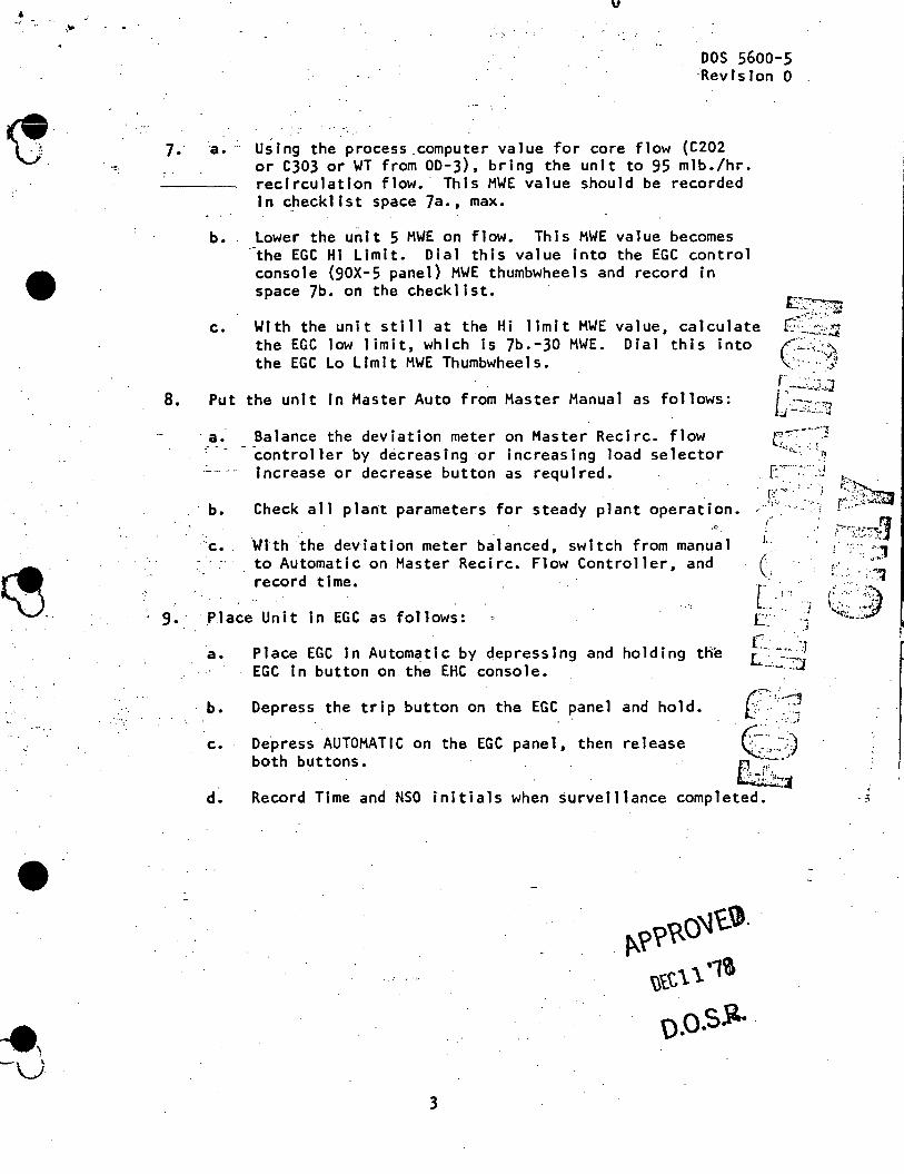
'9 -D:
•
~.·.
•
"'·
v
. ·:·
DOS 5600-5 ·Rev rs ion O
7. -a. - Using the process _computer value for core flow (C202 or C303 or WT from OD-3}, bring the unit to 95 mlb./hr. recirculation flow.· This MWE value should be recorded In checklist space 7a., max.
8.
b.
c.
Lower the unit 5 MWE on flow. This MWE value becomes .-the EGC HI Limit. Dial this value into the EGC control console (90X-5 panel} MWE thumbwheels and record in space 7b. on the checklist.
With the unit still at the Hi limit MWE value, calculate the EGC low limit, which is Jb.-30 MWE. Dial this into the EGC Lo Limit MWE Thumbwheels.
Put the unit in Master Auto from Master Manual as follows:
. a. Balance the deviation meter on Master Recirc. flow
~~ ( .·. '"-: ........ :~ •• J.
. ~- ... ~.,.~'
c:-~·;;
b.
- -controller by decreasing or increasing load selector increase or decrease button as required.
Check all plant parameters for steady plant operation. .. ::;::: ::~
:c. ~tth ~he deviation meter b~lanced, switch from manu~l to Automatic on Master Recirc. Flow Controller, and record time.
9. ·Place Unit in EGC as follows:
a. Place EGC In Automatic by depressing and holding the EGC In button on the EHC console.
b.
c.
d .
Depress the trip button on the EGC panel and hold. c,:__.-g
CF•: De.press AUTOMATIC on the EGC panel, then release both buttons.
:~~ ... /·I '--•' . ...,.l
Record Time and NSO initials when surveillance completed.
3
p..??Ro\l'C.~. \)tC\ \ .,,
0 .o.s.\l. ·
I
l
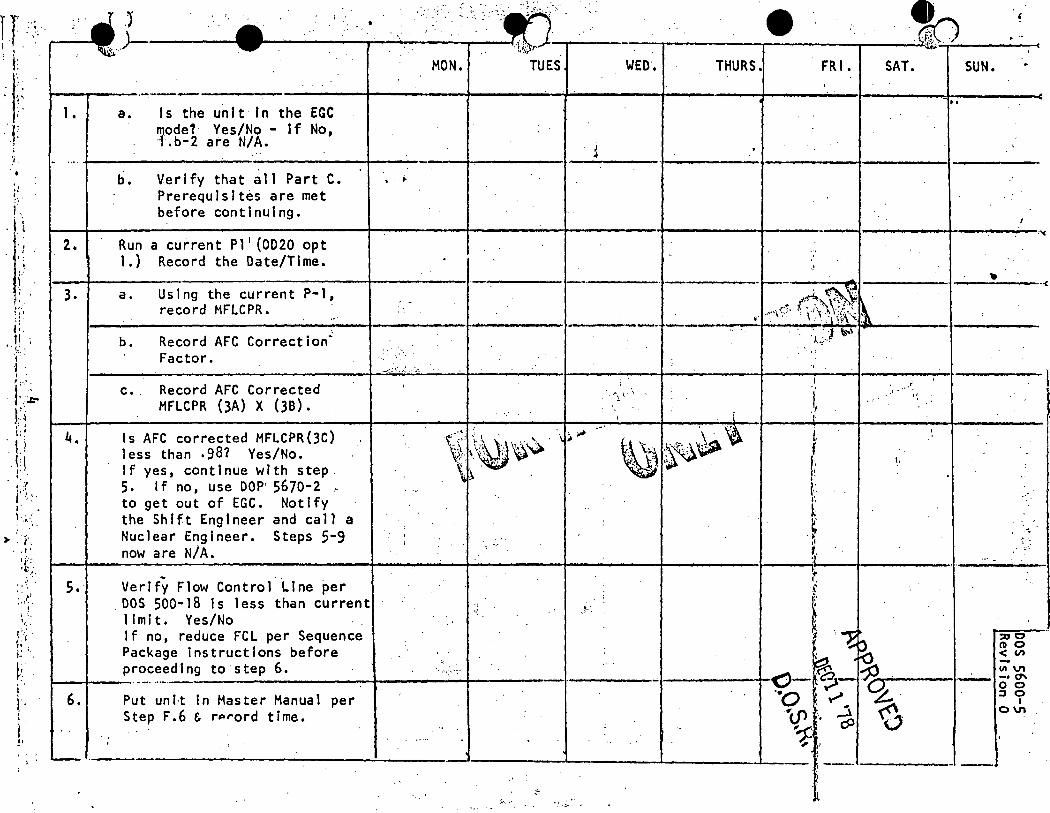
l T ... . "'·. . I · f .. ,:'
i !: ..
) i·· : ~~ ·.· '
·T '.i . .. l. . u . ,·
I
•:
,. . ( .. 1·
I
,,.,. ·l:_;.
' .. !,._,
( . . i !•
•I •
. .1 .,)----~
• • .... MON. TUES THURS. FR I. SAT. SUN.
-----·-··-------------+-----~'------~-----+------r-------1-----""'1------c 1. a. Is the un I t f n the EGC
mode? Yes/No - If No, ·l.b-2 are N/A.
b. Verify that all Part C. Prerequisites are met before continuing •
••
... ' ..
1---+----------------1-------+------1-----+-----~-----1-----------='< 2 •
4.
s.
Run a current Pl I (0020 opt 1.) Record the Date/Time.
a. Using the current P-1, record HFLCPR.
b. Record AFC Correction~ Factor.
c. Record AFC Corrected HFLCPR (3A) X (38).
Is AFC corrected HFLCPR(3C) less than .98? Yes/No. If yes, continue with step S. If no, use DOP' 5670-2 -to get out of EGC. Notify the Shift Engineer and call a Nuclear Engineer. Steps 5-9 now are N/A.
~ . Verify Flow Control Line per
. DOS 500-18 ls less than current limit. Yes/No If no, reduce FCL per Sequence Package instructions before proceed1ng to step 6.
·: ~;'
,.__,.-__ . --·· ··-·-----------+-------+-----6. Put unH In Master Manual per
Step F.6 & rPrord time •
;
. ·"'1 i. ·.,
I .. -~
t ,, I' .. f.": ... l ~ .. .~
r
... t: '. .. •·; ..
t.
·------------~---..:--------'------11-. ..,_ ___ .J..-_____ ..J. ___ . -- ------ -
;...,.• .. .-.,.,· ,
. ;:•
;-- -··--·--.,..~--=--
I
f
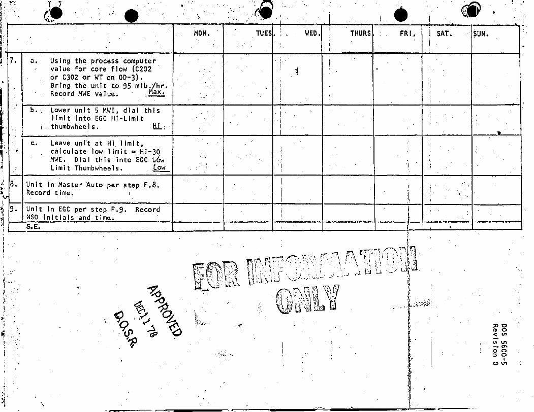
:
:
7,
• ,
.. ;
. ' .. I
.. :
"
.. i
' 8.
v I -I
9. l
l -· .. l I . I
I i :
' I .. · ,. .··
1··::· ... '' . " . J: . ' l ·' ·. ,, .
>'
.d. . .. ., . ~· .
I .. I
~ .. ~
., •• I.
I
a .. Us Ing the process computer I value for core flow (C202
or C302 or WT on 00-3). Bring the Lin It to 95 mlb ./hr.
Max. Record MWE value. ·.-b. ~ Lower unit 5 MWE, dial thl s
J lml t Into EGC HI-Limit J thumbwhee 1 6. lll~
c. Leave unit at HI 1 Im It, calculate low 1 Im It "" Hl-30
; MWE. Dial this Into EGC Low Limit Thumbwheels • ~
Unit In Master Auto per step F.8. necord t lme. I
Unit In EGC per step F.9. .Record NSO Initials and time. - -S.E.
' '
.. ' \
MON.
,;,
..
·····
..
; .. ,
..
:
........,___,_.
'.
H. ~-;.~;.:.
. I
..
. ... 0:- .
.. I
TUES. ! WED. I THURS i v i
I i
I. I
! ! -~
; i
I i
I
I '
i I i
' i I
i I I
• ·-I FR 1 .•
'
I
:
.,
I .. I .I
I ,__ I '.
I SAT. I
I
: J
:,
£:
' ; •I
-
. '
I I
I,
1:;
~ ~~
~UN.
. '
-
•
---
:::ao ID 0 < (/) Ill V1 -0' ' ·o o :s 0
I 0 V1
·~ '
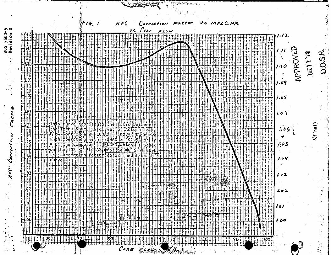
LI\ 0 I oc 00 ..a-L/\ "' -II) > 0 Q) oa:
'V ~
" .~ ~
·O
' .,... ~
t ~
ft ·~
... ; -· _,.
· ... > ,. l
---- ---~ ------~-- . -- -....,..~:•<-~ ·::-·:~.7~,,~,··'X'.,. .... ·:.~::!:-· :~
~ ' : i
/ ., llrC Corre.cJ1of'J Fo..cfo.,- +o ~ l"J. CPA
A .._
SJ 6 er:. 0-
~
r.·or, ! ~
"" 1~os
p
/.o'f
~])
.:;,
·' .. , ·l ··,
.Cf) .I!.':, ·~ ex:. . , .. ;-4 (./) ......... ·. 6. ~ c).
-ra c ·-'+--
I ·I
"
. j 1 ,r I
. >
i '15" . ' ' 'f
t
:~ . :I
'.l •\
I !
> · I · ... : I
· .. . , .
. .. t ..; .,. . ·1
. ~. . .
. ~. \ '' .. , .... .. '.· ..
• I.·.
·1 ••
-~
u.1.:S ..;uvu"'i ; .. ,,. Revision 3
April 1961
MAIN TURBINE TRIP, REACTOR FEEDWATER PUMP TRIP AND FEEDWATER RUNOUT RESET ON HIGH REACTOR LEVEL J
A. PURPOSE
The purpose of this procedure is to confinn the caiibration and operation of the Main Turbine Trip, Feedwater Pump Trip and Reactor I Feedwater Runout Sensors llTS 2(3)-263-59A and -598. .
B. REFERENCES
1. GEK Manual 26915, Table 1, Page 5-1, Reactor Protection System.
· 2. Electrical blueprints.
· a. 12E2358B(l2E3358B), Schematic Diagram - EHC System -Part 2 - Alann and Trips.
b. 12E2395(12E3395), Schematic Control Diagram ~ Reactor Feed Pumps and Auxiliary Oil Pumps -Part 2.
c. 12E2418(12E3418), Schematic Diagram - Feedwater Control System Valve Control.
3. P & ID M-26(M-357), Diagram of Nuclear Boiling and Reactor Recirculating Piping.
C. . PREREQUISITES ·
1. Equipment required.
a. 120-inch HiO Dial M~nometer with source of :pressure.
b. 1/4-inch stainless steel flair· type tubing unionsc·. · with "o" rings.
c. Plastic water bottles and stainless· steel tubing with ···---- fittings.
2.
d. Plastic tubing, approximately 6 feet long •
. e. Sound powered phones.
f. 2 ea. Multimeter (DMM or VOM).
g. Instrument Mechanic tools and supporting material.
Equipment status.
Electro-Hydraulic Control (EHC) Unit ON to check turbine trip logic.
1 of 9 APPROVED
APR22 '81
D.O.S.R.
>
•
•
••
D. PRECAUTIONS
DIS 5600-l Revision 3
1. · Calibration to be perfonned during an outage when the Turbine and Feedwater Pumps are tripped or can be tripped. When the · transmitter is valved out and equalized, .the transmitter will go Upscale tripping the Turbine and Feedwater Pumps.
2. Relays HFA-A and HFA-a, initiated by sensors LITS 2(3)-263-59A and -598 respectively, are in the turbine trip and feedwater pumps' trip circuitry. The logic for the relays is as follows: ..
a. Either relay HFA-A .Q.!: HFA-8 pi.eked up will trip the Turbine.
b. Relays HFA-A and HFA-8 picked up to trip the Feedwater Pumps.
E. LIMITATIONS AND ACTIONS
None. I
. F. ·PROCEDURE
' ·=
1. Notify' the Unit Nu.clear ~tatio!l Operator (NSO) of the intent to perfonn a calibration on sensors LITS 2(3)-263-59A and -598/LI 2(3)-263-lOOA and -1008.
2. To verify the high reactor level turbine trip logic the· following steps will be required prior to loading the level sensors:
a. In the EHC cabinet, D bay, CONNECT a DC Voltmeter (to read +24v) to T8D01-5 and EHC cabinet's ground. RECORD on the attached Main Turbine .Trip and Reactor Feed Pump Runout High Reactor Level Checklist {attached).
b. Remove the trip bus seal;.in relay, XK-26, located i~,! 0-bay. RECORD on the checklist.
NOTE
A 24 volt reading on the turbine . trip bus indicates a turbine trip and a zero volt reading a reset condition •
c. If sensors LITS 2(3)-263-59A and -598 are indicating> 36 inches, remove the cover and tape the .indicator pointers to ~ 36 inches. RECORD on the checklist •. Mark the item "NA 0
if the step is not applicable.
d. Detennine, if necessary, the sensor(s) initiating the turbine trip. Lift, tape and store lead{s) required to clear the trip. RECORD lead(s) lifted on the check- .. list. Leads not lifted mark "NA" in the column.
2 of 9 APPROVED
APR22 '81 .
D.O.S.R.
•
-•
·DIS 5600-1 Revision 3
3. Establish communications with assistant between Instrument· · Racks 2202(3)-5 and -6, sound powered jacks 42 and 44
(75 and 77) and Panels 902(3)-32 and -33,.sound powered jacks 6(85). Conununications will also be required between Instrument Racks 2202(3)-5 and -6 and the Control Room at sound powered jacks 3(53) for the transmitter/indicator calibration.
4. CLOSE both the Ins trurnent Va 1 ves and OPEN the equa 1 i zer on the transmitter to be calibrated. RECORD (v') on the attached Main Turbine Trip, Reactor Feedwater Pump Trip and Feedwater Runout Reset on High ~eactor Level Data Sheet 12 that the instrument is valved out. •
5. Slowly remove the Test Plugs. Ensure that the Instrument Valves are not leaking. Install the flared unions. OBSERVE the precautions for handling materials which may be contaminated.
' 6. Place the water bottle top ring around the high leg (right)
7.
test nipple. CONNECT the water bottles and tubing to the flared unions. Do not tighten the tubing fittings to the unions at this time. - . -· - · · ·
Fill the wat~r bottles approximately half full with clean• demineralized water and allow a small amount of water to leak through the fittings to remove trapped air. -Tighten the tubing fittings.
... · ·~- a-. CONNECT the Dial Manometer to the high leg (right) ·water bottle and CLOSE the equalizer. RECORD on data sheet 12 that the test equipment is connecte.d. ·
.. . . "~
, ,.
9. Remove the tape from t.he indicator pointer ins ta 11 ed in Step F.2.c. on the transmitter being calibrated. RECORD on th~ checklist.
· 10. Apply a differential pressure of approximately 65 inches of water to the transmitter and check for leaks. If the pressure bleeds off in a short period of time, check the Equalizer Valve, tubing connections and the ring on the water bottle for tightness.
11. CONNECT a Multimeter to the terminals listed on the data sheet to monitor the FLOW CONTROL RESET contacts. VERIFY that the contacts are OPEN. ·
12. Verify that the HFA-A and HFA-B relays in Panel 902(3)-29 are. de-energized (dropped out).
13. Slowly DECREASE the differential pressure until the Multimeter indicates that the contacts for FLOW CONTROL RESET are CLOSED •. RECORD the AS FOUND Turbine Trip differential pressure and switch contacts closure verification on data sheet 112.
e APPROVED .. ~~~ . 3 of 9 . APR22 '81.
0.0.S.R.
•,
' ... ~
l
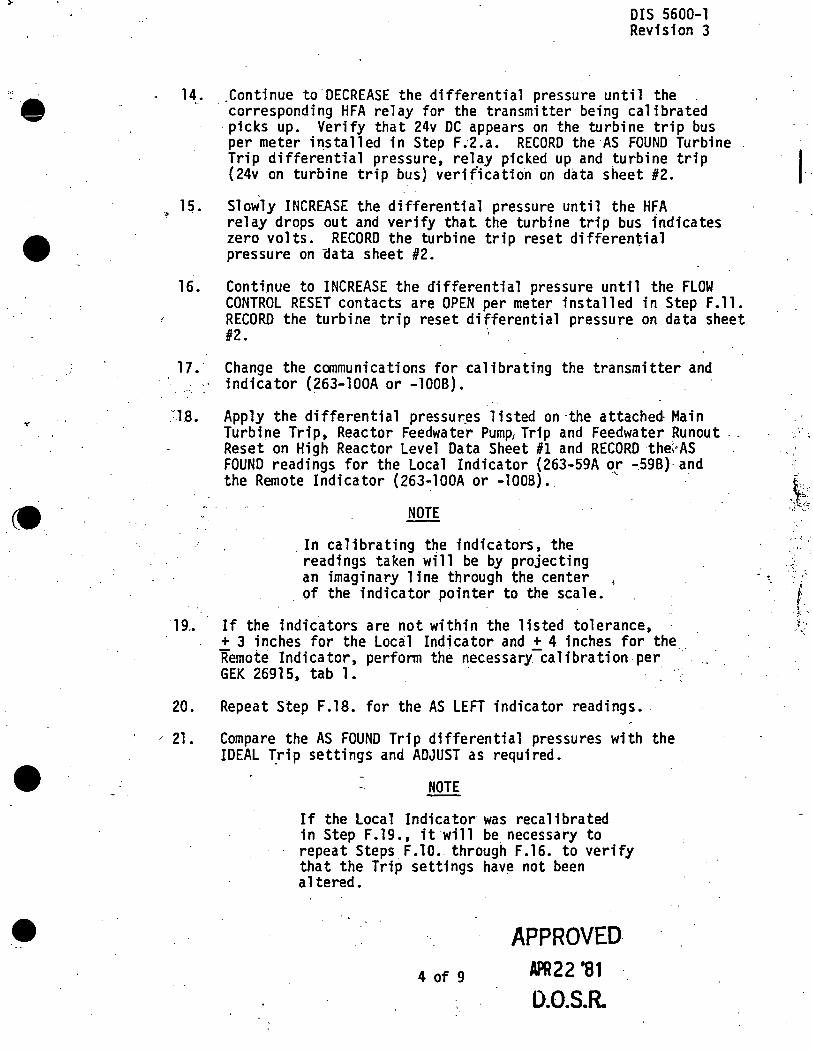
•
•
DIS 5600-1 Revision 3
14. Continue to DECREASE the differential pressure until the . corresponding HFA relay for the transmitter being calibrated picks up. Verify that 24v DC appears on the turbine trip bus per meter installed in Step F.·2.a. RECORD the ·AS FOUND Turbine Trip differential pressure, relay picked up and turbine trip {24v on turbine trip bus) verit'ication on data sheet #2.
15. Slowly INCREASE the differential pressure until the HFA rel ay d raps out and verify that the turbine trip bus fod i ca tes zero volts. RECORD the turbine trip reset differen~ial pressure on aata sheet #2.
16. Continue to INCREASE the differential pressure until the FLOW CONTROL RESET contacts are OPEN per meter installed in Step F.11. RECORD the turbine trip reset differential pressure on data sheet #2. ;
17. Change the communications for calibrating the transmitter and ·' indicator (263-lOOA or -1008).
'.'.18. Apply the differential pressur.es listed on ·the attached- Main Turbine Trip, Reactor Feedwater Pump, Trip and Feedwater Runout .. Reset on High Reactor Level Data Sheet Hl and RECORD the;,As FOUND readings for the Local Indicator {263-59A or -598)·and the Remote Indicator (263-lOOA or -1008). ·.~ .•
NOTE
. In calibrating t~e indicators, the readings taken will be by projecting an imaginary line through the center of the indicator pointer to the scale.
19~ If the indicators are not within the listed tolerance,
20.
/ 21.
+ 3 inches for the Local Indicator and + 4 inches for the Remote Indicator, perfonn the necessary:-calibration per · · GEK 26915, tab 1. .
Repeat Step F.18. for the AS LEFT indicator readings •.
Compare the AS FOUND Trip differential pressures with the IDEAL ~rip settings and ADJUST as required •
NOTE
If the Local Indicator was recalibrated in Step F.19., it will be necessary to repeat Steps F .10. through F .16. to verify that the Trip settings have not been altered.
4 of 9
APPROVED APR22 '81
0.0.S.R.
. ' ·' -
~ ... i;.:; . ..;_.(,; .. ~ ....
.- I,' ,,,
"'
"'
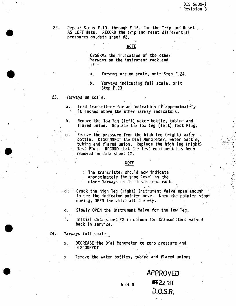
•
•
22.
DIS 5600-l Revision 3
Repeat Steps ,F.10. through F.16. for the Trip and Reset. AS LEFT data. RECORD the trip and reset differential pressures on.data sheet #2.
NOTE
OBSERVE the .indication of the other . Yarways on the instrument rack and if -
a. Yarways are on scale, omit Step F.24.
b. Yarways indicating full scale, omit Step F. 23.
23. Yarways on scale.
a. Load transmitter for an indicatirin of .approximat~ly. 10 inches above the other Yarway indicators.
b. Remove the low leg (left) water bottle, tubing and flared union. Replace th·e low leg (left) Test Plug~.
c. Remove the pressure from the high leg (right) water bottle. DISCONNECT the Dial Manometer, water bottle, tubing and flared union. Replace the high leg (right) Test Plug. RECORD that the test equipment has been
··removed on data sheet 12.
NOTE
lhe transmitter should now indicate approximately the same level as the oth_er Yarways on the instrument rack.
· d~· Crack the high leg (right) Instrument Valve open enough to see the indicator pointer move. Wh~n the pointer stops moving, OPEN the va 1 ve a 11 the way.
e. Slowly OPEN the Instrument Valve for the low leg.
f. Initial data sheet 12 in column for transmitters valved back in service •
24. Yarways full scale.•
a. DECREASE the Dial Manometer to zero pressure and DISCONNECT.
b. Remove the water bottles, tubing and flared unions.
5 of 9
APPROVED APR22 '81
D.0.S.R.
,, .
. : \ ·' . ·. •:•
' '
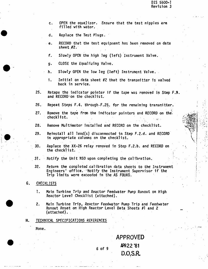
,.
•
;. e
•
25.
26.
27.
28.
29.
30.
31.
32.
DIS 5600-1 Revision 3
c.
d.
. e.
f.
g •
h.
i.
OPEN the equa]izer. Ensure that the test nipples are. filled with water.
Replace the Test Plugs. ·
RECORD that the test equipment has been removed on data sheet .. 12. ·
Slowly OPEN the high leg (left) Instrument Valve.
CLOSE the Equaliz1ng Valve.
Slowly OPEN the low leg (left) Instrument Valve.
Initial on data sheet #2 that the transmitter is valved back in service.
Retape the indicatqr pointer if the tape was removed in Step F.9. and RECORD-on the checklist~
Repeat Steps F.4. through-F.2~. for the remaining transmitte~. .. Remove the tape fran the indicator pointers and RECORD on the"i checklist. ·
• t?_.' .
' . . . Remove Multimeter installed and RECORD on the che.cklfst.
Reinstall all lead(s) disconnected in Step F.2.d. and RECORD in appropriate columns on the checklist.
Replace the XK-26 r.elay removed in Step. F.2.b. and RECORD on the checklist. ·
Notify the Unit NSO upon completing the calibration.
·, ...
Return the completed .calibration data sheets to the· Instrument Engineers' ·office •. ':Notify the Instrument Supervisor if the Tri_p 1 imi ts were exceeded in the AS FOUND.
G. CHECKLISTS
1. Main Turbine Trip and Reactor Feedwater Pump Runout on High. Reactor Level Checklist (attached) •
2. Main Turbine Trip, Reactor Feedw~ter Pump Trip and Feedwater Runout Reset on High Reactor Level Data Sheets #1 and 2 (attached).
H. TECHNICAL SPECIFICATIONS REFERENCES
None.
6 of 9
APPROVED APR22 '81
D.O~S.R.
. : .
'.,
' .
:'r.
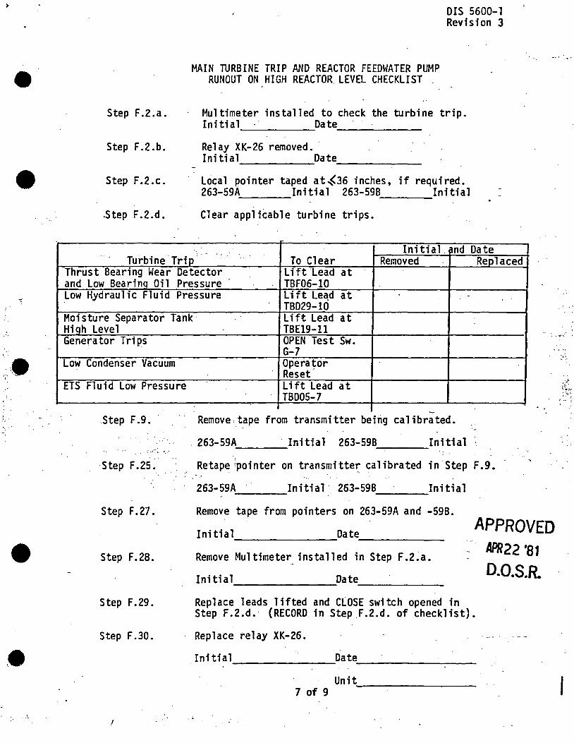
>
•
:;-.... -.'
•
MAIN TURBINE TRIP AND REACTOR FEEDWATER PUMP RUNOUT ON HIGH REACTOR LEVEL CHECKLIST .
DIS 5600-l Revision 3
Step F .2 .a. Multimeter installed to check the turbine trip. Initial Date ------
Step F.2.b. Relay XK-26 removed. · Initial Date ------
Step F.2.c. Lo ca 1 pointer taped at ~36 inches, if required. 263-59A Initial 263-59B Initial
. Step F.2.d. Clear applicable turbine trips •
· .. '• '' Initial. md Date
Turbine Trip To Clear Removed Replaced Thrust Bearing Wear Detector Lift 'Lead at and Low Bearino Oil Pressure TBF06-10 Low Hydraulic Fluid Pressure lift Le~d at
TBD29-10 Moisture Separator Tank: Lift Lead at Hiqh Level TBE19-11 Genera tor Trips OPEN Test Sw.
·. ,,,_,.· .
Low Condenser Vacuum
ETS Fluid Low Pressure
Step F.9 •
· ...... , . . . ·.
Step F .25.
Step F.27.
Step F. 28.
Step F .29.
Step F.30.
I
G-7 .. I ~,
Opera~or Reset Lift Lead at TBD05-7
~-
Remove. tape from transmitter beirig calibrated.
. 263-59A · Initial 263-59B Initial " . ---- ----Retape.)pointer on transmitte~ calibrated in Step F.9.
263-59A Initial· 263-59B Initial ---- ----Remove tape from pointers on 263-59A and -598.
Initial Date ------- ------Remove Multi meter_ installed in Step F .2.a.
Initial Date --------- ------
APPROVED APR22 '81 0.0.S.R.
Replace 1 eads lifted and CLOSE switch opened in Step F.2.d. (RECORD in Step .F.2.d. of checklist).
Replace relay XK-26.
Initial Date ------- --------Unit --------7 of 9
~~-
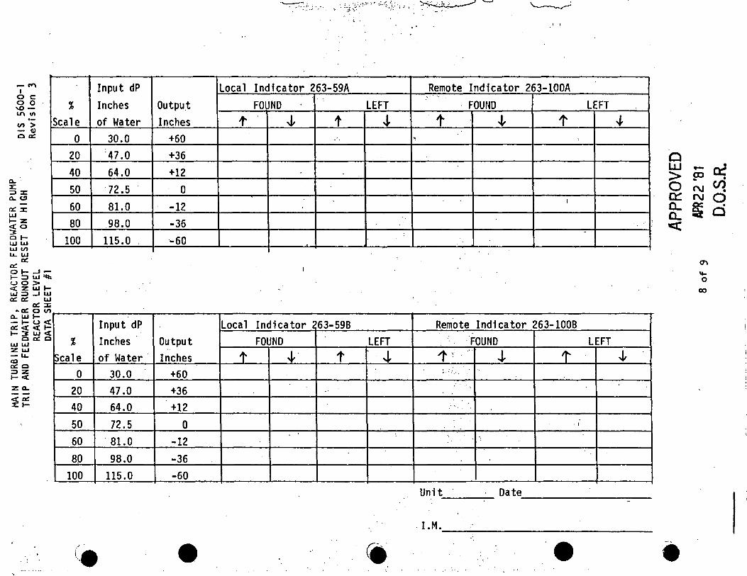
- "" I oc 00 'l.0-1.1\ Ill
V) > - Q) c a::
0. 4 :::> :c 0. CJ
a::: ::c LlJ 1-Z <to 3 OlLl.J LlJ LlJ V) u.. LL.I
a:: a:: OI- ..J-1-:::> LLJ'l:t: UO> <t z LL.I 1-1.JJ :::> ..J LL.I a:: a:: LL.I
a:: :Ii ~a:: 0 V)
0. LL.I 1-- I- u< a::<< 1-1-::J: LLJ < c a:: c LlJ LL.I :z LL.I - u.. al a:: c :::>Z I-< zo.
~:=
Input dP % Inches
Scale of Water 0
20 40 50 60 80
100
%
Scale 0
20 40 50 60 80
100
{A .,.
30.0 '47.0 64.0
:72.5 81.0 98.0
115.0 '
Input dP Inches of Water
30.0 47.0 64.0 72.5 81.0 98.0
115.0
Output Inches
+60 +36 +12
0 -12 -36 -60
Output '.
Inches +60 +36 +12
0 -12 -36 -60
•
·~·.~· . .: ~ .· ;;> ~:~•,>'C 't,. ~::..~::<.t_.: ·; 1 . l ~ "-": ~
'· .1 I
Local Indicator 263-59A .Remote Indicator 263-lOOA FOUND
'.
LEFT · FOUND LEFT t' J, t J. t J, t .J,
. . ...
I
-
Local Indicator ?63-598 Remote Indicator 263-1008 FOUND LEFT FOUND LEFT
t ~· t 4- 1·; .. .i t J,
; ........ . ''
..
'I .. ·• . •,
Unit Date ------------~-----
. l.M. ---~---------------------------------
• •
c LLJ - a:: > PJ • ON~ 0:: N Q a.. ~ . a.. 0 <
e
°' "-0
co
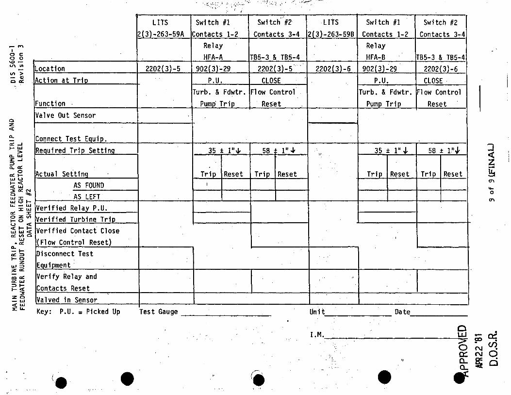
,.
- "" I 0 c 0 0 '° ·-L.1' Ill
C/) > Location
- C1) 0 a:: . Ac ti on at Trio
0 z <(
a.. a:: ..J I- LIJ
> a.. LIJ ::c _, :::> a.. a::
0 a:: 1-LIJ u I- <( <( LIJ
3 a:: "' 0 =it: UJ :J: UJ <.!J tu.; - LIJ
:J: LIJ a:: :J: 0 z Cl)
I- 0 u <( <( t- tLIJ LIJ <( a:: C/) 0
LIJ - a::
a.. - la:: :::> l-0 z w :::> z a:: ca a:: a:: LLJ :::> .... t- :i zo - UJ <( UJ ::c u...
Function Valve Out Sensor
Cor:mect Test EQuip. ReQuired Trip Settino
Actua 1 Setting AS FOUND
. AS LEFT.
Verified Relay P.U. Verified Turbine Trio Verified Contact Close (Flow Control Reset) Disconnect Test Equipment · Verify Relay and Contacts Reset
'
Valved in Sensor Key: P.U. = Picked Up
(e
LITS Switch #1 Switch· #2 2(3)-263-59A Contacts 1-2 Contacts 3-4·
Relay HFA-A TB5-3 & TB5-4
2202(3)-5 902( J)-29 2202( 3)-5 ·. ..
P.U. CLOSE Turb. & Fdwtr. Fl ow Control
Pumo· Trip Reset
-
35 ± l""' 58 1: 111 ""
Trip Reset Trip Reset I
Test Gauge ~------------------
• (. ' ·•
LITS Switch #1
2(3)-263-598 Contacts 1-2 ' Relay
HFA-B 2202(3)-6 902(3)..:29
P.U. Turb. & Fdwtr.
Pump Trip
'.'! .. 35 ± 111 .J,
Trip Reset
'I
.. ·'
Unit Date
J.M.
:: .. ~ i· ..
,.
•
Switch #2 Contacts 3"."4
TB5-3 & TB5-4 2202(3)-6 CLOSE ·
Fl ow Control Reset
58 ± l.''J.
Trip Reset
0 LLl
0 0::: 0... a.. ..
-a:> . N N
f&
'] <( z -~ °' .... 0
°'
• a:::: • en • 0 . Cl
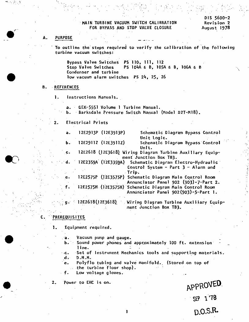
;· 1 ..
•
•
A.
~- .· ...
PURPOSE
. ·.··
··HAIN TURBINE VACUUM SWITCH CALIBRATION FOR BYPASS AND STOP VALVE CLOSURE
DIS 5600-2 Revision 2
August. 1978
- To outline the.steps required to verify the calibration of the following turbine vacuum switches:
Bypass Valve Swiiche~ PS 110, 111, 112 Stop Valve Switches PS 104A & B, 105A & B, 106A & B Condenser and turbine low vacuum alarm switches PS 24, 25, 26
B. . REFERENCES
";. ~' ·i:,. •
. :·, .- .
1. Instructions Manuals.
a. GEK-5551 Volume 1 Turbine Manual. b. · Barksdale Pressure Switch Manual (Hodel D2T-M18).
. 2. Electrical Prints
a. 12E2913P (12E3913P) Schematic Diagram Bypass Control Unit logic.
b. 12E2911Z (12E3911Z) ·Schematic Diagram B~pass·control Untt.
c. 12E2618 02E36181 Wiring Diagram Turbine Auxiliary Equipmeni Junction Box TB3.
· d. 12E2359_A· (12E3359.A) Schemati.c Diagram Electro-Hydraulic· Control System - Part 3 - Alarm and Trip •
. e. 12E2575P (l2E3575P) Schematic Diagram Hain Cqntrol Room Annunciator Panel 902 (903)-J-Part 2.
f. 12E2575H (l2E3575H) ·schematic Diagram Hain Control Room Ann~riciatot Panel 902(903)-5-Part 1.
.. g. : 12E2618lJ2EJ618l . Wiring Diagram Turbine Auxiliary Equipment Junction Box TB3.
C. . .. PREREQUISITES
1. Equipment required .
. a. Vacuum pump and gauge. b. · Sound pewer phones. and appr~ox imate ly 100 ft. ex tens ion
1 i ne. -c. Set of Instrument Mechanics tools and supporti~g materials. d~ D.H.H.
· e. Polyflo tubing and valv~ manifold._ {Stored on top of the turbine ~loor shop). · ·
f. Low voltage gloves.
2. Power to EHC is on. f\?PRO'Jt.0.
StP 1··1s
o.o.s.R.
... , ....
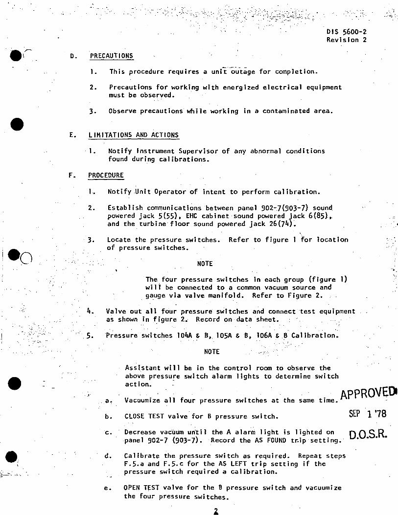
•
·.; .. .' · . ._·.. . -_ ... :
•
. . -.· ~· ., ... . .. ·~
.. · · : , --.\ - _. ,; ...... :,· · ,_ '--.:::{- ... ~:· .. J,_':·:"·i:L~,~·~.~:.~~;)~~ .: .. :: z· ... :·· ~ .' ,:_~ ·>
D. PRECAUTIONS
1. This procedure requires a unit outage for completion.
DIS 5600-2 Revision 2
2. Precautions for working with energized electrical equipment must be observed. ·
3. Observe precautions while working in a contaminated area •
E. LIMITATIONS AND ACTIONS
· 1. Notify Instrument Supervisor of any abnormal conditions found duri.ng calibrations.
F. PROCEDURE
1~ Notify .Unit Operator of intent to perform calibration.
2.
3.
Establish communications between panel 902"."7(903-7) sound powered jack 5(55), EHC cabinet sound powered jack 6(85)., and the turbine floor sound powered jack 26(74)~
'· Locate the pressure switches. Refer to figure 1 for location of pressure switches.
NOTE
The four pressure switches in each group (figure 1) wili be connected to a common vacuum source and g~uge via valve manifold. Refer to Figure 2. , .
4. Valve out all four pressure switches and connect ·test equipment as shown in ~igure 2. Record on data sheet.
' .. 5. Pressure switches 104A & B, 105A & B, 10.6A & .B Calibration •
NOTE
Ass lstant wi 11 be in the contro 1 room to observe the above pressure switch alarm lights to determine switch
.. ::
··;.
·~ ..
action. -. . if: . · APPROVED
Vacuumize all four pressure switches at the same time. -.. a~
b. CLOSE TEST valve for B pressure switch. SEP 1 '78
c. Decrease vacuum un'til the A alarm light is lighted on QQSR panel 902-7 (903-7). Record the AS FOUND tr:ip setting.· • • • •
d. Calibrate the pressure switch as required. Repeat steps F.5.a and f.5.c for the AS LEFT trip setting if the pressure switch required a calibration.
e. OPEN TEST valve for the B pressure switch and vacuumize the four pressure switches.
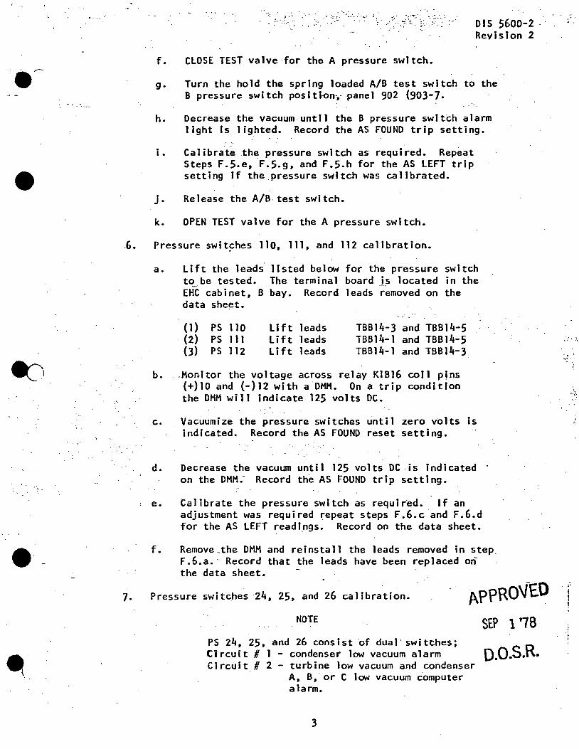
•
~)
•
·-·.• . ......
,· .. ·
f. CLOSE TEST valve for the A pressure switch.
DIS 5600-2 · Revision 2
g. Turn the hold the spring loaded A/B test switch to the' B pressure swl tch pos I tlon-,- pane 1 902 (903-7.
h. Decrease the vacuum until the B pressure switch alarm light Is lighted. Record the AS FOUND trip setting.
i . Calibrate the pressure switch as required. Repeat Steps F.5~e, ·F.5.g, and F.5.h for the AS LEFT trip setting If the pressure switch was calibrated •
j. Release the A/B test switch.
k. OPEN TEST valve for the A pressure switch •
. 6. Pressure swit~hes 110, 111, and 112 calibration.
7.
a. Lift the leads· 11 sted be low for the pressure swl tch to be tested. The terminal board J.s located in the EHC cabinet, B bay. Record leads removed on the data sheet.
b.
(1) . (2)
(3)
PS 110 PS 111 PS 112
Lift leads Lift leads Lift leads
TBB14-3 and TBB14-5 TBB14-1 and TBB14-5 TBB14-1 and TBB14-3
-Honi tor the voltage across re 1 ay Kl B 16 co i 1 pins {+)10 and (-)12 with a DMH. On a trip condition the OHM will indicate 125 volts DC.
c. . Vacuumize the pressure switches until zero volts is indicated. Record the AS FOUND reset setting.
d. Decrease the vacuum unt i1 125 vo 1 ts DC . is indicated on the OHM.-· Record the AS FOUND trip setting.
e. Calibrate the pressure switch as requir~d. If an adjustment was required repeat steps F.6.c and F.6.d for the AS LEFT readings. Record on the data sheet.
f. Remove_the OHM and reinstall the leads removed in step. F.6.a.- Record that the leads have been replaced on the data sheet.
Pressure switches ·24, 25, and 26 calibration.
NOTE
APPROVED SEP 1 '78
PS 24, 25, and 26 consist of dual· switthes; Circuit# 1 - condenser low vacuum alarm Circuit# 2 - turbine low vacuum and conde~ser
A, B, or C low vacuum computer a la rm.
3
o.o.s.R.
·.':' . . \
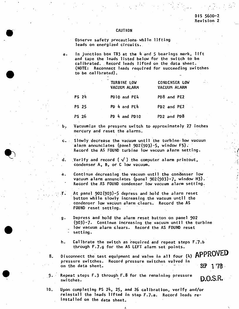
--
•
• e
'
a.
.b. .
CAUTION
Observe safety precautions-while lifting leads on energi~ed circuit~ •.
DIS 5600-2 Revision 2
In junction box TB3 at the 4 and 5 bearings mark, lift and tape the leads listed below for the switch to be calibrat~d •. Record leads lifted on the data sheet. (NOTE: Reconnect leads required for succeeding switches to be calibrated).
TURBINE LOW CONDENSER LOW VACUUM ALARM VACUUM ALARM
PS 24 PDlO and PE4 PD8 and PE2
PS 25 PD 4 and PE4 PD2 and PE2
PS 26 PD 4 and PDlO PD2 and PD8
·vacuumize the pres~ure switch to approximately 27 inches mercury and reset the alarms.
c •. Slowly decrease the vacuum until the turbine· low vacuum ·alarm annunciates (panel 902(903)-5, window F5). · Record the AS FOUND turbine low vacuum alarm setting.
d. Verify and record ( .J) the computer alarm printout, condenser A; B, or C low vacuum.
e.
';; ,f •
Continue decreasing the vacuum until the con~enser low vacuum alarm annunciates (panel 902(903)-7, window HJ).· Record the AS FOUND condenser low vacuum alarm setting.
At panel 902(903)-5 depress and hold the alarm reset . button while slowly increasing .the vacuum until the
condenser lat1 vacuum alarm clears. Record the AS FOUND reset setting.
g. Depress and hold the alarm reset button. on panel 902 (903)-7. Continue increasing the vacuum until the turbine low vacuum alarm clears. Record the AS FOUND reset
- setting.
h. Calibrate the switch as ·required and repeat steps F.7.b. through F.7.g for the AS LEFT alarm set points.
8. Disconnect the test equipment and valve in all four (4) APPROVED pressure switches. Record pressure switches valved in
9.
·on the data sheet. SEP 1 '78 · Repeat steps F.3 through F.8 for the remaining pressure swi tche·s. o.o.s.R ..
10. Upon completing PS i4, 25, and 26 calibration, verify and/or reinstall the leads lifted in step F.7.a. Record leads reinstalled on the data sheet.
\
. ~·· .-.\
··:
r '
•
;j ,r·
i I·
•
'.:t" • • ..... -- t> . · ,_ .. .. . ~ . .~ . - .. . .. '. ~:· ..
• ~ "! . . . -.,::. - ·.~::_:: .- .
DIS 5600-2 Revision 2
11. · Notify the NSO that the calibration has been completed.
12. · Request the Radiation Protection-D~partment to ~urvey the polyflo tubing and valve manifold. Bag and stow tubing and manifold on top of the turbine floor shop.
G. CHECKLISTS
1. Stop Valve and Bypass Valve Vacuum Switches Data Sheet.
2. Computer and Annunciator Turbine Low Vacuum Alarm Data Sheet.
H. TECHNICAL SPECIFICATIONS REFERENCE
1. 3. 1 bases, page 29
•: ••• ~-· !:".
·:,'
5
''
APPRO\JEO.
sa> 1 ·1a·
0.o.s.R.
~.
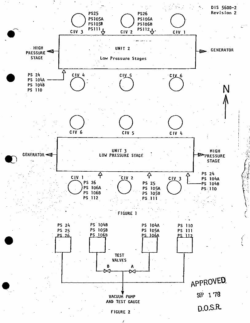
•
•
. HIGH PRESSURE
STAGE
OPS25 PSlOSA PS 1058
. CI V 3 PS 111 0 CIV 2
UNIT 2
PS26 PS106A PS106B PS112Q.
Low Pressure Stages . ,,, ..
PS 24 _j PS 104A O= PS 104B PS 110
GENERATOR
'·,·
0 0 CIV 6 CIV 5
UNIT 3 Low PRESSURE STAGE
CIV 1 '( -C IV 2 .0 PS 26 0 • PS 106A ·•.· PS 1068
.
PS 112
• FIGURE 1
PS 24 PS. 1048 PS 25 PS 1058
PS 1068
TEST VALVES
B A
VACUUM PUMP AND TEST GAUGE
FIGURE 2
'f PS 25 PS lOSA PS 1058 PS .111
PS 104A PS 105A p
:. .. ..
0 CIV
0 CIV 4
DIS 5600-2 Revision 2
GENERATOR
N
t. . .
HIGH PRESSURE
STAGE
LPS 24
CJ PS 104A PS 104B PS·: 110
..
PS 110 PS 111
APPROVEO.
SEP .1 '70
o.o.s.R.
. r \..
(
' ...

APPR0~ .. 19 SEP
swiTCHES •• ". ,. ·, ; .
:_··:'". 1-' , .... -··-·-- ...... _ .. : -··-·· -·-·-·---·---------
~.17~ESS~RE SWITCH 104A ,.· ·,.- PRESSURE SWI T ·-' 04B ..
SENSOR VALVED OUT. 'SENSOR VALVED· OUT
D.O. c~ .. ,).I"\ •. Tolerance + l"vac Tolerance!. l"Vac - . ...
IDEAL FOUND LEFT ·IDEAL FOUND .EF I . - ·-· .. , :
TRIP 19" Vac-1- ·TRIP. 19 11· Vae
--·· f-•
RESET 2011 Va ct · RESET 20 11Vact ..
Sensor Valved In : se.nsor Valved In
Pressure swt tch ~OSB ;· Pressure Switch 106A
~ '.:.·i ..
Sensor Valved Out .. .. .Sensor Valved Out - To l era nee .-t: 111Vac · .. Tolerance .:!:. 111Vac -
IDEAL FOUND LEFT· . ·, IDEAL· FOUND LEFT ------T$1P 1911 Vac4- '
·~ ... TRIP · 19 11 Vac4 !
RESET 20 11 Vac+ : RESET 2011 Vac1 -
Sensor Valved In Sensor Valved In ''" ..
I'
•' RVPASS VtilV!= VAr.UUM SWITr.H!=S Pressure Swl tch 110 Pressure Switch 111
Sensor Valved Out Sensor Valved Out .. ·
Lifted Lead T~.!E.~ .. - LI f ted. Lead TBB14-l ---· __ J._LfJ;ed .~~~d._}B~J~.:.5.. __ Lifted Lead TBB14-5
Tolerance + lTTVac Tolerance +l 11Vac -IDEAL FOUND LEFT IDEAL FOUND ·- LEFT -
TRIP 711 Vact TRIP 7" Vac .j.
-----··--· ----·--- ·----- --'
"'"" ~ ... , ..... , RESET 811 Vact RESET. 811 Vac +
·- ·----··---· .. -. RelUiif~~ 1-~C!~-. .I~~].4_".'.L ···--···-····-----·--·- .11.e..J?. laced Lead TBB14-1
Replaced Lead TBB14-5 Replaced Lead TBB14-5 -
Sensor Valved In I Sensor Valved In ·------···· . ' .. . ~- ~ . .,
• PRESSURE SWITCH 105A ~ ... _.)-::
SENSOR VALVED OUT
Tolerance !. l"Vac IDEAL r-OUND LEFT -· TRIP· 19"Vac.i.
RESET 2011Vact
Sensor Valved In
Pressure Switch 106B
Sensor Valved Out .. Tolerance~ 111Vac
IDEAL FOUND ·LEFT
TRIP 19"Vac .j.
RESET 20 11Vac +
Sensor Va 1 ved. In I i I
Pressure Switch 112 .
.Sensor Valved Out --------· ----
Lifted Lead TBBl4;_1
LI f t~d Lead TBBl4-3 Tolerance + l "V ae
IDEAL FOUND LEFT
TRIP 711 Vac4-
RESET 8" Va ct
Reolaced Lead TBB14-t Replaced Le~d TBB14-3
Sensor Valved In
. ,. •'
-r
. ,.
.. . .. ,
VI c:: -t )> 0 n ,, c:
... . '·
c: c:: . 3:-;::. .... VI C:: :c l'T1
-t )> •nz :cc · ..
IT1 ·(·~
VI OJ ':~ -< ' . 0 ,, ..... )> )>. -f VI )> VI ... ,".
"' c:: :: . :c )>. ,''
~~.·;._ -I 1"1. ·;'
.... !.
:· .. ,.
::ioo-' Cl> - , < VI
Ill \11. -· °' .· . 0 O· ::Io.-.:
; '
I ~· . N.;«· ~: ;.. .
. .... ; ~ .
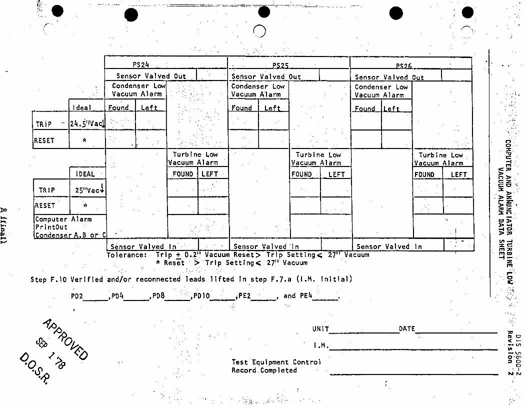
r-. . x· A :':\· ... ,.. . . • c-=.::"'='·-·:·--~-~-="'--=~-:':'. ... -_;·:::-· ---·-::· --:-·-:-~~---' ......... - .. .
.. ,.r··. ' 0
PS24 r.s2r:; Sensor Valved Out I . ·sensor Valved Out
Condenser Low .. Condenser Low Vacuum Alarm ...
' Vacuum Alarm •" ·, .. " .. " . . . .
Ideal Found Left Found Left ..
-.· :
TRIP - 24.S'.IVac; · .. ·. '. '.
" ' ...
RESET . ,'c .... :. . . I I :-.:..
Turb 1.ne Low Turbine Low Vacuum Alarm Vacuum A la rm
ID~AL FOUND LEFT FOUND LEFT
TRIP 25''Vac!
• e . .r--,:
PC:'1C.
Sensor Valved Out Condenser Low Vacuum Alarm ~ ... q,,n I l!>ft
Turbine Low Vacuum Alarm FOUND LEFT
·'
·: l "
. ._;:. ' ,",
'l,'' .. •
n . o. :C. ~ c: , -f . ""' .. < :::u
)> . n::J> c:::z. C: IC .'. :c ,, ... ::
~- )> z: RESET * Computer Alarm '
.Printout .' "
I ICl'lndP.Mer A_ B or· ·C . - _, . ' -
Sensor Valved In .. Sen~alved ·in Sensor Valved In I
II Ill Tolerance: Trip+ 0.2. Vacuum Reset> Trip Setting<; 27 Vacuum * Reset · > Tr Ip Sett Ing< 2711 Vac;uum .
:~ .. '. '. .. .
Step F.10 Verified and/or reconnected leads llfted In .step F47.a (J.M. Initial)
PD2 ,P04 ,PDB . .'··,Poto ;PE2 --~- ---~ ----- -~~
and PE4 ---,'•·
UNIT DATE --------- ---------~
I,·
l.M. ____________________________ ~
Test Equipment Control Record.Completed
s: e"·' ~~. C)> )> -f ~O· >:o V1 ~. :cc: . ,,, :0 ITI o:1 -f - . z: .
""' .~'" " 0 . a:·
'":-../:
• I ; ~
::0 ~c <" -
. - V'I Ill -vi o-o-:J 0
0 ' I
NN
':;·
)
••
•
•
A. PURPOSE
MAIN STOP VAL VE < 10% CLOSURE HALF SCRAM
DIP 5600-3 Revision 0 July 19ao· ·
To outline the steps to test and verify the main Stop Valve limit Switch (SVOS) operation for scram function and 90% Closure limit Switch (SVMT).
B. REFERENCES
1. Manuals~·
GEK-5551, Volume 1, Steam Turbine - Generator Instructions.
2. Electrical Blueprints.
a. 12E2624A & B (12E3624A & B) Wiring Diagram·~ Turbine Auxiliary Equipment - Main Stop Valves ~ Part~ 1 & 2.
·b. l 2E2465(12E3465) Schema tic Diagram - Reactor Protection System - Channel A.
c. 12E2466(12E3466) Schematic Diagram - Reactor Protection System ~ Channel B. ·
d. 12E2911S(l2E3911~) Schematic Wiring Diagram - Main Stop Valve No. 2.
J!. 12E2913E(l2E3913E) Schematic Wiring Diagram - Valve Test logic - Part 3.
C. PREREQUISITES
1. Main Steam Isolation Valves closed.
2. · . Tu.rbine can be reset. ·
3. . Test equipment and material required.
a.· An eight (8) pen test recorder.
b. 4 - 47 + 3 ohm resistors •
~- 4 - 1 k ohm resistors.
d. 4-"D"batteries.
D. PRECAUTIONS
None.
E. LIMITATIONS AND ACTIONS
None.
1 of 7
APPROVED JUL 22'80
o.o.s.R.
- ~ ·,
. . i
l
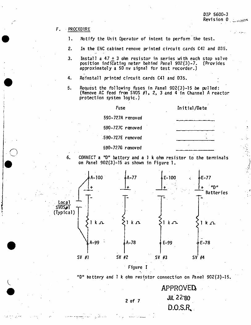
•
•
DIP 5600-3 Revis ion 0 _ -~--~ _··p
F. PROCEDURE
1. Notify the Unit Operator of intent to perfonn the test.
2. In the EHC cabinet remove printed circuit cards C41 and 035.
3. Instal 1 a 47 + 3 ohm resistor in series with each stop va 1 ve position indicating meter behind Panel 902(3)-7. (Provides approximately a 50 mv signal for test recorder.)
4. Reinstall printed circuit cards C41 and 035 •
5. Request the following fuses in Panel 902(3)-15 be pulled: (Remove AC feed fran SVOS #1, 2, 3 and 4 in Channel A reactor protection system logic.)
6.
Fuse
590-727A removed
590-727C removed
-590-727E removed
590-7276 removed
CONNECT a "D" battery and a on Panel 902(3}~15 as shown
A-100 177 + -
Initial /Date
1 k ohm resistor to the terminals in Figurel.
1100 ·•. l-77 . : "D"
. ·~
Batteries
Local SVOS,,1
(Typical}
1 k .n. 1 k ..0. 1 k ..n. 1 k .n.
A-99 - A-78 E-99 E-78
sv 111 sv 113 sv· 114
Figure I
"D" battery and 1 k ohm resistor connection on Panel 902{3).;.15.
2 of 7
. .'
APPROVED JUL 22'80
D.O.S.R, .
•• '!'.:: .••..
• ·'
·' - ;, . ' ..
.. r
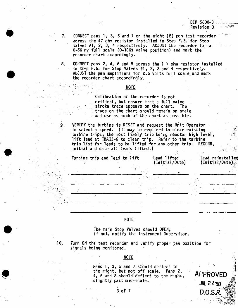
•
•
•
•• .___
7.
DIP.. 5600-3 ... -~-~--~---Revisfon o .. .,. ... ,,_......
CONNECT pens 1, 3, 5 and 7 on the eight (8) pen test recorder · -:::·:across the 47 ohm resistor installed in Step _F. 3. for Stop Valves #1; 2, 3, 4 respectively. ADJUST the recorder for a 0-50 mv full scale (0-100% valve position) and mark the recorder chart accordingly.
8. CONNECT pens 2, 4, 6 and 8 across the 1 k ohm resistor installed in St~p F.6. for Stop Valves #1, 2, 3 and 4 respectively •
9.
... '. ·· .
. •·.··· -
10.
ADJUST the pen amplifiers for 2.5 volts full scale_and mark the recorder chart ~ccordingly • • ·i: •
. .· - NOTE
Calibration of the recorder is not critical, but ensure that a full valve stroke trace appears on the chart. The trace on the chart ·should ranain on sc.ale and use as much of the chart as possible.
VERIFY the turbine is RESET and .request the Unit Operator to select a speed. (It may be required to clear exis.tfng turbine trips; the most likely trip.being reactor high. level, lift lead at TBA32-6 to clear trip. Refer to the turbine trip 1 ist for leads to be lifted for any other trip. RECORD, .initial and date all leads lifted.}
. : .-.. l- ... -
Turbine trip and lead to 1 ift Lead 1 ifted (Initial/Date}·
Lead reinstalleQ ( Ini ti a 1 /Da tel\!;~
'"·'·
· ..
NOTE
The main Stop Valves should OPEN; if not, notify the Instrument Supervisor.
Turn ON the test recorder and verify proper pen position for signals being monitored.
NOTE
Pens 1, 3, 5 and. 7 should deflect to the right, but not off scale. Pens 2, 4, 6 and 8 should'deflect to the right, slightly past mid-scale.
3 of 7
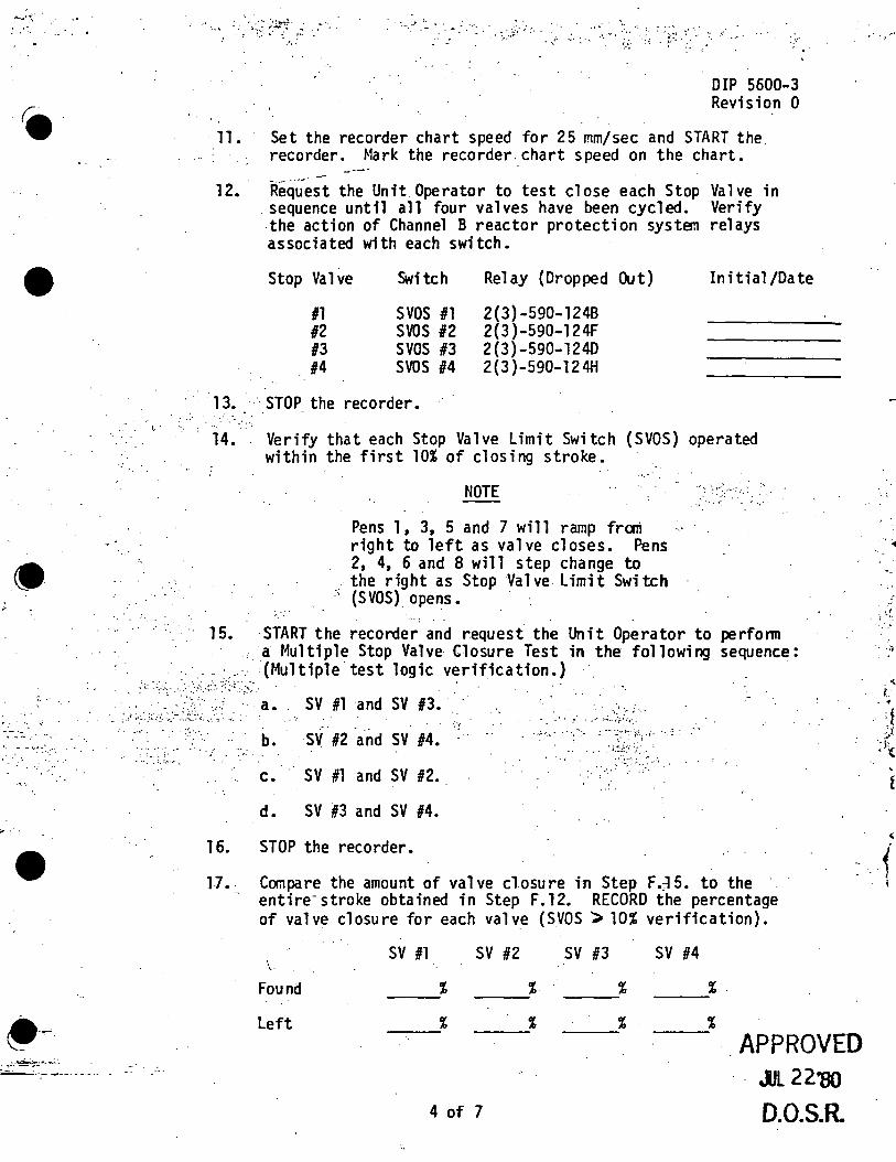
- ........ .
•
. ". '(.
•. - ..... ~ ::-:·. . . ;.
> .·
•
,. .. ...::•.±. :_ •. ~ ·. ~-·- ---·--·-
11.
12.
":- .> 1. ~ . ·. .. . .. .
:»·
DIP 5600-3 Revision 0
Set the recorder chart speed for 25 mm/sec and START the recorder. Mark the recorder.chart speed on the chart.
Request the Unit Operator to test close each Stop sequence until all four valves have been cycled. .the action of Channel B reactor protection system associated with each switch •
Stop Valve Switch Relay (Dropped Out)
#1 svos #1 2(3)-590-1248 #2 svos 12 2(3 )-590-l 24F #3 svos 13 2(3)-590-1240 #4 svos #4 2(3)-590-124H
Valve in Verify relays
Initial /Date
13. · ·STOP the recorder • . ·. ·.·.···: ·· .. 14. Verify that each Stop Valve Limit Switch (SVOS) operated
within the first 10% of closing stroke.
15.
NOTE
Pens l, 3, 5 and 7 will ramp fran right to left as valve closes. Pens 2, 4, 6 and 8 will step change to the right as Stop Valve Limit Switch ·
.,
' (SVOS) opens. · ·
....... '·,·
START the recorder and request the Unit Operator to perfonn a Multiple Stop Valve Closure Test in the following sequence: '(Multiple test logic verification.) "
·:< ·~~:··~· ... :.~ . SV #1 and SV 13. · .. . -.~1 ;- f. • •
' ·"' ....... ~ .. · .,, b.
-:1;·
· sv · 12 -a.nd sv #4. • R~ •,. 0 • • •• •• ••
... . ... '.• ~ . ,, . . ...... . ~ ... _ . . .
c. SV #1 and SV #2 •. .. _,·
d. SV #3 and SV #4.
16. STOP the recorder.
l7.. CClf'i'lpare the amount of valve closure in Step F.;15. to the - entire-stroke obtained in Step F.12. RECORD the percentage
of valve closure for each valve (SVOS ";> 10% verification).
sv #1 sv #2 \.
Found % % --- ---Left % % --- ---
4 of 7
sv 113
% ---% ---
sv #4
%. ---% --- APPROVED
-lJl 22'8()
0.0.S.R.
··. ·1'
• <;
t . . ' l
' f I
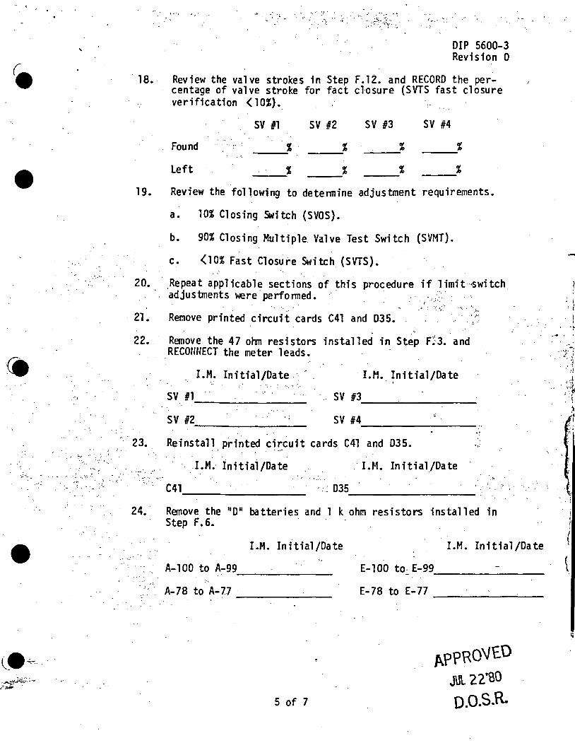
.. ~
•
•
'
.·'.i
·. " ~... . .. ',£•·.··
• ·: c•._
.. . : .... ~~- .·. :... . '• ~: . ...
. '_ .. '··:
DIP 5600-3 Revision 0
· 18. Review the valve strokes in Step F.12. and RECORD the percentage of valve stroke for fact closure (SVTS fast closure verification ( 10%).
sv #1 sv #2 sv #3 sv #4
Found % ·. % % % --- --- --- ---% --- % % ---_._;% Left
19. Review the following to detennine adjustment requirements.
a. 10% Closing Switch {SVOS).
b. 90% Closing Multiple Valve Test Switch (SVMT).
c. <10% Fast Closure Switch (SVTS).
20. ·.Repeat applicable sections of this procedure if limit·-<Switch
. 21.
22.
adjustments were· perfonned. · ' {
. .. - ~ : . ·'. . ~:-~· •P'•: •'
"' Remove printed circuit cards C41 and D35. . ......
R~ove the 47 ohm resistors installed in St~~ F~:3 •. and RECONNECT the meter leads.
I.M. Initial/Date.·· · I.M. Initial/Date .. sv #1 -------- sv #3
~--------------
sv #2 --------0 sv #4 ______________ _ ';
23. Reinstall printed cir,:cuit cards C41 and D35. ., '~·
24.
- _: ~ .·:.
I .M.· Ini tiai /Date · I.M. Initial/Date
C41 --------------- ':: D35 __________ _
Remove the 11 0 11 batteries and 1 k ohm resistors installed in Step F. 6.
I.M. Initial/Date ·,,
A-100 to A-99 ---------A-78 to A-77 · -------
5 of 7
I.M. Initial/Date
E-100 to- E-99 --------E-78 to E-77 --------
APPRO\IED JUL 22.~0 o.o.s.R.
~ i
•I • i
\ . 'j-
... 1 __ , .. . ·:~
~ . ~
; I
I \
( \

. '
•
.· ~ . .. ~ :· \: '·.· . ·:: . . . . . . . :·:~ . . .......
.. - .. ·.: .· ·.: ~ . . .. . . .~ .....
.. :·
... =
. ...:·;i ........ ,. ' I • • •' . :.;~.~ ~ ..;
·- .·
DIP 5600-3 Revision 0
25. Request the Operator reinstall the fuses 'renoved in Step F. 5.
Fuse I.M. Initial /Date Fuse I.M. Initial /Date
590-727A
590-727E
590-727C
590-727G
26. Verffy that the following relays are energized:
Relay ·(Panel 902(3)-15)
Relay (Panel 902(3)-17) {y)
590-124A 590"".1248
590-l 24C 590-1240
590-124E 590-124F .• .. , .
590-124G 590-124H .• y~;:·~ >-'--' ... ' . "'· . •. ...... --. -.. -
'. i ..... :'.•:, .. '.;~:/;~:\:''~:>'-; '''~/·;_ .::/: :',:.._: ; NOTE ... '
- .;: ,,
.. _ ..
Stop Valves should be open. If ' ~· . '
, .. · . .. . . - ·. ~ .. :··
the relay fails to energize, notify . the Instrument Supervisor. -
'... '-
27 •.. · Request the Unit Operator to test close each Stop Valve. . · Instrument Mechanic to verify proper relay operation.
~·
Stop Valve · . · Relay Panel Cv? #1 590-124A 902(3)-15 #1 590-1248 . 902(3)-17 #2· .· 0 :590-124C-. '>902(3)-15
. #2 .. :-< 590-.l 24F / . : '~'.'_·~· ·:· 90J ( 3 )-17 . 13 . - .. 590-124E. . -- 902(3)-15 ,_ ---: .. · #3 590-124D 902(3)-17
. #4 . 590~124G 902(3)-15 #4 590-124H 902(3)-17
·!
. ~· . .
:.'.:.>· 2a.- ·Reinstall any leads lifted in Step F.9. RECORD lead reinstalled · · · ·· in- space provided at Step F:9. . - . . -
. 29. Notify the. Unit Operator that the test has been· canpleted.
30. Notify the Instrument Supervisor of any abnonnalities encountered during the perfonnance of this test.
-·
6 of 7
f\P?R0'1£0 J.\\. '2. 2 'SO
0 .o.s.R.
·':"
<-c .,, .. .... ;
·~ -~~ :).
"·
... :A . ~ -
<(
·. ~·

··a .. ~ •.
•
.. ; . ~ '" ··.: -; .:. ~
,· .
.. , ...
' '/ -~·· . . '.":. . . ~ '.
-- .:-:J- .: .·.;_-
. . ,- . . - \ '. . .
. . . . . . . .
.,·;
•'·:. ~ ··, ..
" ,.
:. ~ . . .. '
.G. CHECKLISTS
Incorporated within the procedure.
H. TECHNICAL SPECIFICATIONS REFERENCES
Table 3.1.l. (supJX>rt). •
.. .... •.
:~ . . .-.-·· ::-- . .,. ..
. .. . ·-(
_._,, .. . '" - .... ~·· .-. : -~' .. ~ . -
. ~ ........ ,..-. . _,
·;. ..... . .. . ~-··;,.~::-~.-;-· 1 ·: ... ~-}' ;~·~.;. ••• , ..
·;.· .. ·. •· ...
· .•
-- ::: - _.::.. _,_,_ - ··- -
....... :-:
7 of 7 lFINALl
DIP 5600-3 Revision 0
... .• i~
<
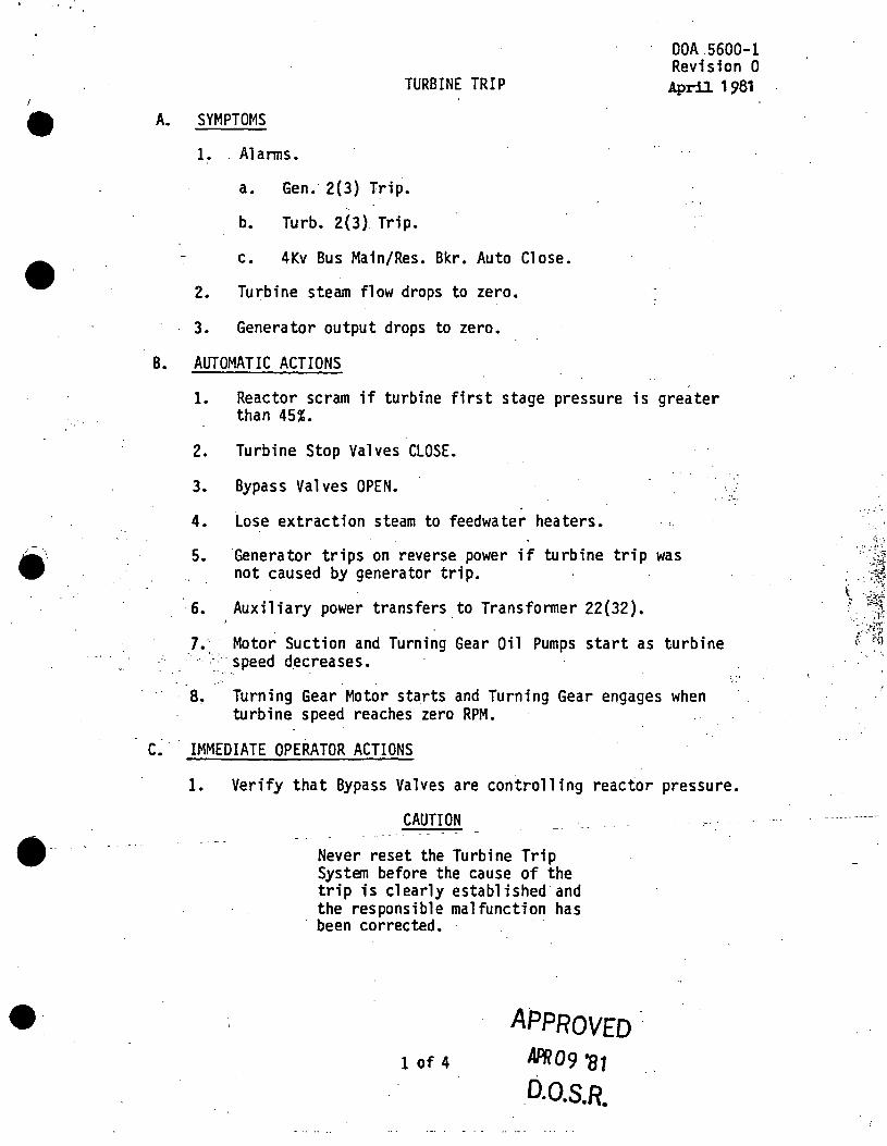
••
••• . . . '
·--
e·
A.
B.
DOA.5600-1 Revision 0
TURBINE TRIP April 1981
SYMPTOMS
1. . Alanns.
a. Gen. 2(3) Trip.
b. Turb. 2(3} Trip.
c • 4Kv Bus Main/Res. Bkr. Auto Close.
2. Turbine steam flow drops to zero.
3. Generator output drops to zero.
AUTOMATIC ACTIONS
1. Reactor scram if turbine first stage pressure is greater than 45%.
2. Turbine Stop Valves CLOSE.
3. Bypass Valves OPEN.
4. Lose extraction steam to feedwater heaters. . ~.
5. ·Generator trips on reverse power if turbine trip was not caused by generator trip.
6. Auxiliary power transfers to Transfonner 22(32).
7 •·· · Motor Suction and Turning Gear Oil Pumps start as turbine '' ~ speed decreases.
8~ Turning Gear Motor starts and Turning Gear engages when turbine speed reaches zero RPM.
: .. :·
C. . IMMEDIATE OPERATOR ACTIONS
1. Verify that Bypass Valves are controlling reactor pressure.
CAUTION
Never reset the Turbine Trip System before the cause of the trip is clearly established and the responsible mal functfon has been corrected.
1 of 4
APPROVEDAPR09 '81
_D.O.S.R.

•
•
2. Verify that turbine speed is decreasing.
DOA 5600-1 Revision 0
a. If turbine speed is decreasing, proceed to Step C.3.
b. If turbine speed is not decreasing, VERIFY that the Main Stop Valves· (MSV's) are CLOSED.
(1) I~ th~ MSV's are closed, TRIP the Main Gen~~erator by opening· both Output Circuit Breakers •
- .-•
(2) If the MSV' s are not closed, SCRAM the Reactor,'· CLOSE the Main Steam Isolation Valves (MSIV's) and VERIFY that the Main Generator TRIPS.
3. 'START the Emergency Bearing Oil Pump.
' ·4. VERIFY that the Main Generator TRIPS on reverse power.
S. Verify that auxiliary power transfers to Transformer 22(32). . · .. ;
D. SUBSEQUENT OPERATOR ACTIONS ' . ~ ' ... -
1. Verify that bearing oil pressure is normal.
2. VERIFY that the Motor Suction and Turning Gear Oil Pumps START as turbine speed decreases.
3.
4.
s.
Reduce recirculation flow to minimum observing power/ fl ow l imitations. ·
START the Lift Pumps as turbine speed drops below 900 RPM. ·-- . ·:·~
· ·-. CAUTION
. Oil temperature to the bearings should be 85-90°F when the Turbine comes to rest to avoid "slip sticking" on Turning Gear.
SET the Turbine 011 Cooler Outlet Temperature Controller at 90°F •
6. Maintain condenser vacuum and seal steam pressure if the MSIV's are open.
7. Verify that Turning Gear·. engages as· the _Turbi_ne slows to approximately zero RPM. ·
a. If Turning Gear engages, proceed to Step 0.8.
~~ APPROVED 2 of 4 APR09 '81
D.0.S.R.
\
'o,.
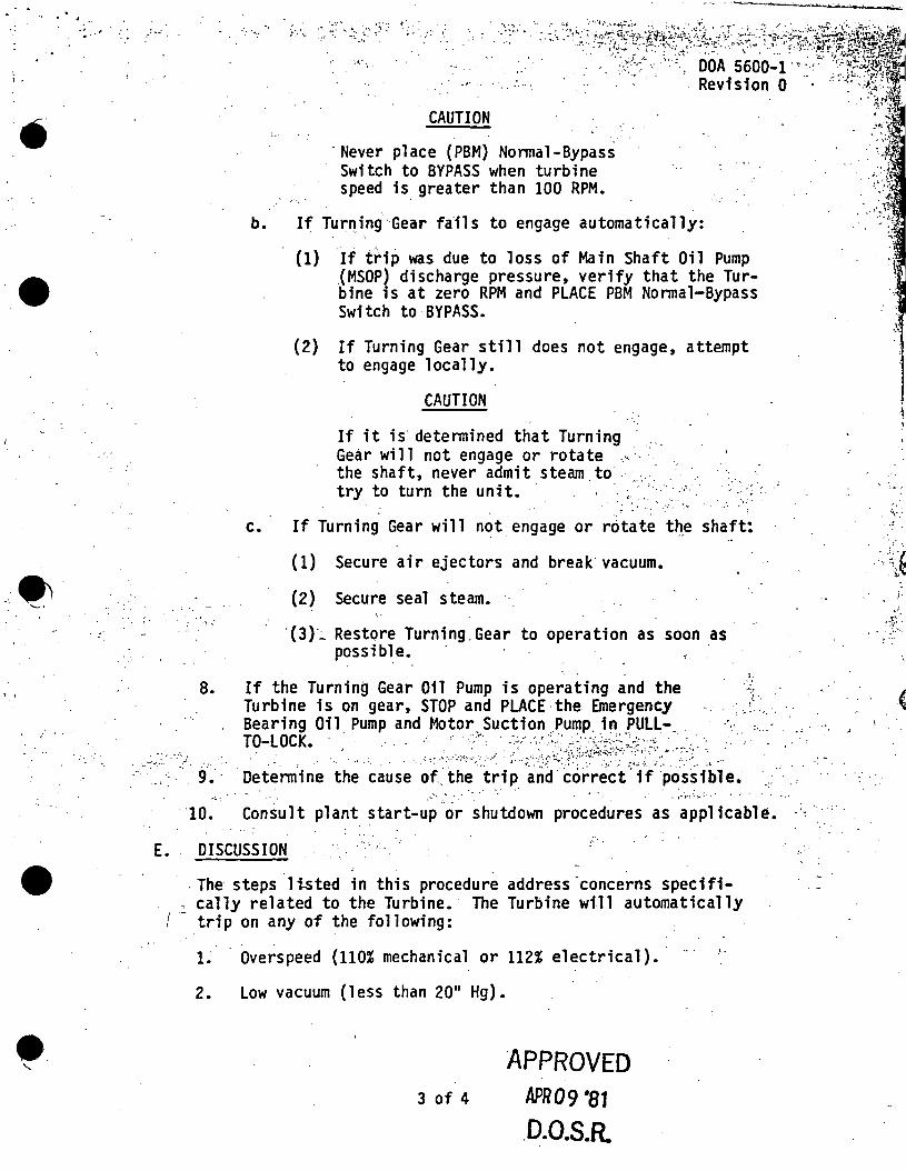
. , -: .. ,. . . . __ ; ~ .. · .
••
•
•••• '-•
' '
E.
• e. '-
, ;
8.
. ,·.,.
CAUTION
·Never place (PBM) Nonnal-Bypass Switch to BYPASS when turbine speed is greater than 100 RPM •
,·_ ..
b. If TurnJng ·Gear fails to engage automatically:
(1) If trip was due to 1 oss of Ma in Shaft Oil Pump .(MSOP) discharge pressure, verify that the Turbine is at zero RPM and PLACE PBM Nonnal-Bypass Switch to BYPASS.
(2) If Turning Gear still does not engage, attempt to engage locally.
CAUTION
If it is· detennined that Turning . Gear wil 1 not engage or rotate .·· . · the shaft, never admit steam to . . try to turn the unit. · ··· · · ··' · .. ·: ··
~. ·· ... -~ -... - ...
c. If Turning Gear will not. engage or rotate t~.e shaft:
(1) Secure air ejectors and break· vacuum •
(2) Secure seal steam. "
· {3)-.:_ Restore Turning Gear to operation as soon as possible.
If the Turning Gear Oil Pump is operating and the Turbine is on gear, STOP and PLACE·the Emergency Bearing Oil. Pump and Motor ... Suction ,Pu~p. i~ .PULL-.
-.. -· ·,, ',
TO-LOCK · . · :· :"·' ·,, · : --··:~ ·~ .. -..:. . ·> • ·. ·. ·. ·.. . . . . • · .. :,; ):'. .. :::,,,~.,·::< :,'.,~·':;Jt:~)''.·;;·:;iA.~~:·;"~~:·~:·::·:.~·~;>.: '., .
· 9. · Detennine the cause of the trip and correct if ·possible. '_ · .. . - . ,
-:.: . ,·t·<'· ... =··. . , .
. , ~
. 10. Consult plant start-up or shutdown procedures as applicable. -« · ..
DISCUSSION
. The steps ·1 tsted in this procedure address -concerns specifi- cal ly related to the Turbine. The Turbine will automatically
trip on any of the following:
1. · Overspeed (110% mechanical or 112% electrical). ·
2. Low vacuum {less than 20" Hg).
3 of 4
APPROVED APR09 '81
.D.0.S.R.
'·
.. , ,;
., 1 !
i·
.(
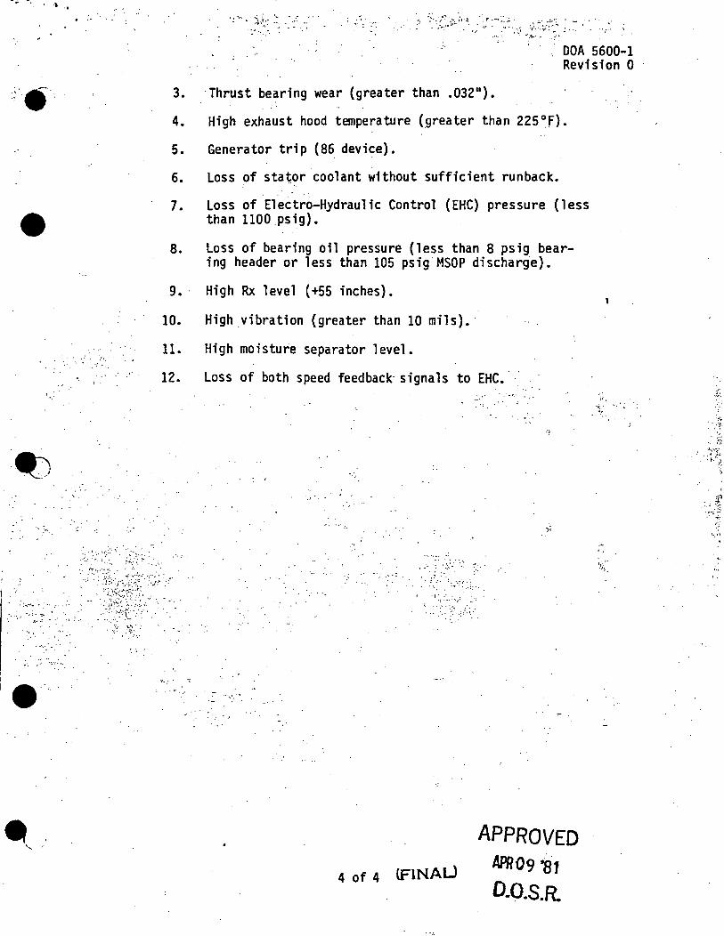
. \ ·•
• . ' . ~ ,' ·.
·~
-" ~ ......
. . . . . ;-... --. ·:·· .·····
- :~, ._ .
j• I
~, .. ·
-r·.-.• ~~;. ·~ .: . ... . ... · . ._; .,. !,,\ ~~~··/·~-:;.. . ~ . . . ... . .,
•••• •• :'I,.·~ •• : .
DOA 5600-1 Revision 0
3. ·Thrust bearing wear (greater than .032 11).
4. High exhaust hood temperature (greater than 225°f).
5. Generator trip (86 device).
6. Loss of sta~or coolant without sufficient runback.
7. Loss of Elect~o-Hydraulic Control (EHC) pressure (less than 1100.psig} •
8. Loss of bearing oil pressure (less than 8 psig bearing header or less than 105 psig MSOP dischar~e}.
9. · High Rx level (+55 inches}.
10. High vibration (greater than 10 mils).·
11. High moisture separator level.
12. Loss of both speed feedback· signals to EHC •
··'·.". : ...... ,,
"-.'."'
··,
. . · .. , .. ... . ,
• < ~ ••
. ~· :.
. . . ~. ·.:.~ ... ··:· : ....
4 of 4 lFlNAU
APPROVED APR09 -81
D.0.S.R.
,.,
... '.
/._~..:.;,~ . ~ ·f~ .... .-. , .•
\ .
,. '··

• . y -5t;~· ·;.:::-" '
(
e
•
,;•.,.
" - '~ .
•
RELIEF VALVE FAILURE
..... , ·~:.: :.:.".:/·. ( .• '::;:· ... :. :::)':-..:: . ' -· " .. ..
· OOA 250-1 Revision 0 Ma7 1981 ·
A. SYMPTOMS
1. El ectromatic Relief Valve Open Alann.
2. Target Rock Relief Valve 2(3)A Open Alann.
3. Valve Leak ~tector System High Temp. Alarm •
4. Acoustical Monitor.Actuated Alann. • 5. OPEN indication for Relief Valve.
B. AUTOMATIC ACTIONS
IF steamino to the Main Condenser, the Turbine Control Valves or the Bypass Valves would close to compensate for the relief val ve ' s fl ow.
C. . IMMEDIATE OPERATOR ACTIONS
. . ·~
' ~ . . .
l. MONITOR and maintain the reactor water level using multiple level indications.
.CAUTION
The Reactor shall be scrammed from any operating condition · if torus tempera tu re reaches 110°F.. .
2. MONITOR the torus water temperature and log every five mi:n-. .. .. utes during heat addition and for a minimum of 30 minutes~.:· . · .. .after heat addition is believed terminated. RECORD data ·
...... • : ·,:.'. .. : on DOP 1600-TI. . . ~:" > ;':".;.~·: :!•·. -
.. ·.. .. · ::. / 0 •. ': .. SUBSEQUENT OPERATOR ACTIONS
· l. · IF the Relief Valve has spuriously actuated and remains open or is stuck open,
a~ Attempt to CLOSE the Relief Valve by cycling the control switeh from BUTO(MANUAL) to OFF and OFF to AUTO(MANUAL) several times. · ·
CAUTION
Valve position indication is de-energized when fuses are pulled •. Confirmation of valve closure must be made by observing the Valve Leak r:etection Tempera tu re Recorder and the Acoustical Monitor on Panel 902(3)-21.
1 of 6
APPROVED MAY07 '81
D.O.S.R.
·,~
'"' : ·~:TI ~·. ~~:·.
. ;:'T.·
., .. · ; ,.·r
. 1 . - . '~
.Ill ----- - ·--- - -- .,,,,-
A
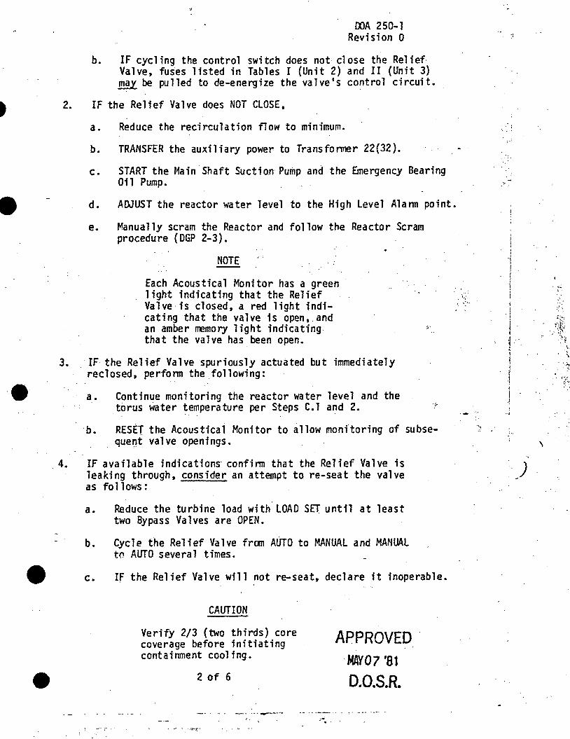
•
·e
OOA 250-1 Revision O
b. IF cycling the control switch does not close the Relief· Valve, fuses listed in Tables I (Unit 2) and II (Unit 3) may be pulled to de-energize the va 1 ve • s contra l circuit.
2. IF the Relief Valve does NOT CLOSE,
3.
a. Reduce the recirculation flow to minimum.
b. TRANSFER the auxiliary power to Transfonner 22(32).
c. START the Main· Shaft Suction· Pump and the Emergency Bearing 011 Pump.
d. ADJUST the reactor water level to the High Level Alann point.
e. Manually scram the Reactor and follow the Reactor Scram procedure (DGP 2-3).
NOTE
Each Acoustical Monitor has a green light indicating that the Relief Valve· is closed, a red 1 ight indicating that the valve is open, and an amber memory light indicating. that the valve has been open.
IF the Relief Valve spuriously actuated but immediately reclosed, perfonn the following:
a. Continue monitoring the reactor water level and the torus Water temperature per Steps C. l and 2.
·b. RESET the Acoustical Monitor to allow monitoring of subseque~t valve openings.
. 4. IF available indications· confinn that the Relief Valve is leaking through, consider an attempt to re-seat the valve as fol lows;
a. Reduce the turbine load with LOAD SET until at least two Bypass Valves are OPEN.
b. Cycle the Relief Valve fran AUTO to MANUAL and MANUAL tn AUTO several times.
• c. IF the Relief Valve will not re-seat, declare it inoperable.
CAUTION
Verify 2/3 (two thirds) core coverage before initiating containment cooling.
2 of 6
-- ·-· ..,....---.: ... . .... '
APPROVED. ·MAY07 '81
D.0.S.R.
-- ~,,
:.· .. :
,.. . '
i I
! ·i
! 1 t i
. j
1 t i ' ' ~ .,
.. ·. ) '
• 1;.. ,.
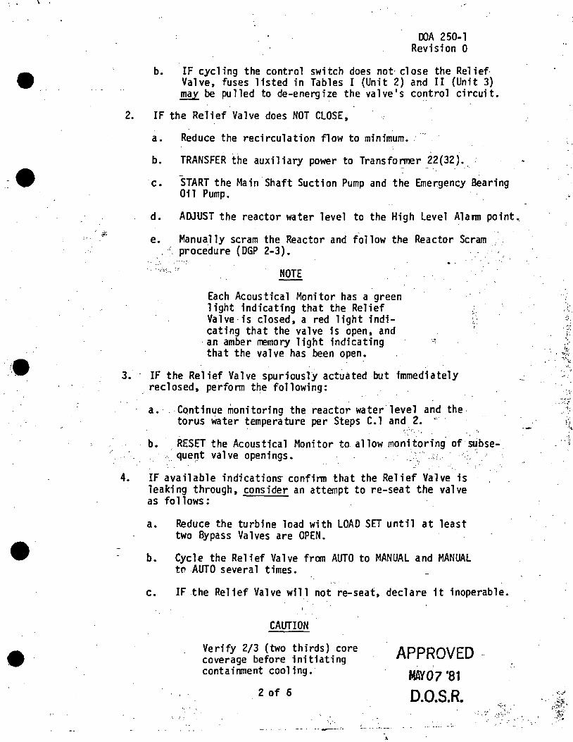
\ .
• :•. ·1;
•
OOA 250-1 Revision 0
b. IF cycling the control switch does not· close the Relief Valve, fuses listed in Tables I (Unit 2) and II (Unit 3) may be pulled to de-energize the valve's control circuit.
2. IF the Relief Valve does NOT CLOSE,
a. Reduce the recirculation flow to minimum •. ····
b. TRANSFER the auxiliary power to Transfonner 22(32) •
c. START the Main Shaft Suction Pump and the Emergency searing Oil Pump.
d. ADJUST the reactor water level to the High Level Alann point._
e. Manua.l ly scram the Reactor and fol low the Reactor Scram .. ·- procedure {DGP 2-3). _ .
. . • :. :- ·,. ·. > ..... ·:. ~ ... ~ :' NOTE
Each Acoustical Monitor has a green light indicating that the Relief Valve·is closed, a red light indicating that the valve is open, and
·an amber rremory light indicating that the valve has been open.
3. · IF the Relief Valve spuriously actuated but immediately .· reclosed, perfonn the following:
a.·. -Continue monitoring the reactor water.level and the. torus Water temperature per Steps C. l and 2 •
. •, . .
'. ' . ..... '
b. RESET the Acoustical Monitor to allow moni taring. of· Stibse-. :· __ que~t valve openings. ~--.~'.,:.· ~
4. IF available indications- confinn that the Relief Valve is leaking through, consider an attempt to re-seat the valve as fol lows:
a. Reduce the turbine load with LOAD SET until at least two Bypass Valves are OPEN •
b. Cycle the Relief Valve fran AUTO to MANUAL and MANUAL tn AUTO several times.
c. IF the Relief Valve will not re-seat, declare it inoperable.
CAUTION
Verify 2/3 (two thirds) core coverage before initiating containment cooling.
2 of 6
· .. ·. -. ..,_.---· ..
APPROVED MAY07 '81
0.0.S.R. . .
-· ---· - ...
.., f· .,
·" 1i; . " . ~,-.:
. :·-. .... ·i!..
. ~ ~-....... ,
'···'.·.f:
...~.,:A-
· - ;•:~~~ -~f~:
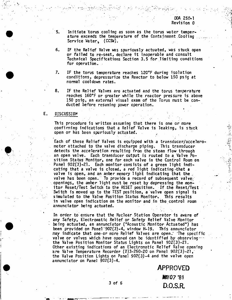
: '.~ ... :. •.~· I•,•.•
•
,_.,
•
-· ·.·-.. :·:· .
.. - ... .~·. ;. , .. ,_ '" . .!I"'•~- . ~-~--~::··.: ·• ·.~·~ .... : • :~·'" "' ·:-.~· ',"-·;: ....
OOA 250-1 ReviS1on O
·s. Initiate 'torus cooling as soon as the torus water tenper- · ature exceeds the temperature of the Contajnment .Cooling ..... ··.- .. Service Water, {CCSW). ·
6. IF the Relief Valve was spuriously actuated, was stuck open or failed to re-seat, declare it inoperable and consult Technical Specifications Section 3. 5 for limiting conditions for operation. . ·
7. IF the torus tenperature reaches 120°F during isolation conditions, depressurize the Reactor to below 150 psig at nonnal cooldown rates.
8. IF the Relief Valves are actuated and the torus temperature reaches 160°F or greater while the reactor pressure is above 150 psig, an external visual exam of the Torus must be conducted before resuming· power operation. ..
E. DISCUSSIOfll
This procedure is written assuming that there is one or more. confinning indications that a Relief Valve is leaking, is stuck open or has been spliriously actu_ated. ~
Each of these Relief Valves is equipped with a transducer/accelerometer attached to the valve discharge piping. This transducer detects the acceleration resulting from the steam flow through an open valve. Each transducer output is routed to a Valve Position Status Monitor, one for each valve in the Cont'rol Roan on Panel 902(3)-21. Each monitor consists of a green light indicati-tig that a valve is closed, a red 11 ght in di eating <that a valve is open, and an amber memory light indicating that the.-valve has been ·open.·· To provide a record of subsequent valve~·
· . openings, the amber light must be reset by depressing the moti~ itor Reset/Test Switch to the RESET position. ·If the Reset/Test
·switch is moved up to the TEST position, a ·valve open signal is simulated to the Valve Position Status Monitor ... This results in valve open indication on the monitor and in the.control roan annunciator being actuated. ·
In order to ensure that the Nuclear Station Operator is aware of any Safety, Electromatic Relief or Safety Relief Valve Monitor
- being actuated, an annunciator {"Acoustic Monitor Actuated") has been provided on Panel '902(3)-4, window H-19. This annunciator may indicate that one.:.or more Relief Valves are open.- -Tue specific valve or valves which have opened can be identified by· ob-serving--the Valve Position Monitor Status lights on Panel 902(3)-21. Other existing indications of an Electromatic Relief Valve opening are Valve Temperature Recorder (2)3-260-20 on Panel 902(3)-219 the Valve Position Lights on Panel 902(3)-4 and the valve open annunciator on Panel 902(3)-4.
3 of 6
·r. ·::. . .-rir--'"\-·~~"";; ··-·--- - - -- -· ..,,..- --
APPROVED llMY07 '81
D.O.S.R.
.. · ·':i.: .;..
:~~l
~ !•.
·:. ·~·: ~~;: r ~. ~~·
'.,:'.,,
\. }~:
•:'•

r!~~~.·.:i#;d~t=ffl;. ··~ .2_:-175·.-.~~:_:~~.-. ··--... ~ -· .. ~-· ~.
~
•
. ·-' ,.,; .....
• ' l.
':"····
-·.:
The Relief Valves discharge below the water level in the Torus, whereas the Safety Valves discharge to the drywel 1 atmosphere. · If a Safety Valve were leaking in a manner sufficient to provide
......... -- ... , .. -indication, ... it .. would .be handled in accordance with Slow Leak (DOA 040-1). If a Safety Valve were inadvertently lifted and/or stuck open, it would constitute the equivalent of a break and the response of .the Operator would be in accordance with Loss of eo·olant (Break Inside Drywell) (DGA-1) •
A Relief Valve stuck open or spuriously actuated is ·not a major transient fran the standpoint of the reactor or turbine operation. It is significant in that it constitutes an unreplenished drain fran the steam cycle. It is also significant because of the resulting heatup of the torus water and the temperature restrictions encountered with such a heatup.
The Immediate Actions are concerned with the torus temperature limitations. The requirement to monitor the torus temperature· for a minimum of 30 minutes after heat addition terminates is intended to provide back-up indication that the Relief VAlve has fully closed or fully re-seated. . ,__. _ ...
''· ··.-,:,
For a stuck open Relief Valve, the steps to cycle ·the co.ntrol switch and pull fuses would be of little or no helpjf the failure were mechanical in nature. However, if the valve stuck open because of.an electrical contact failure, those steps would be meaningful.
The actions to be performed prior to a manual scram presume time to perfonn···them;-- ·With· signi-ficant-degradattons--this time-may-not---·
. . . :· exist and under such circumstances the Operator should initiate an ·. · .. ··_.:.·-~~_:_:: .... , 'inunediate scram .signal.
:.··,·;': ';· ·,. ' .. . .
'.: •.... \..
·:·· ..
The more probable failure is a leaking Relief Valve. Determ.ination of a leaking valve versus a spuriously opened valve is not e~sy. .
, Temperature indication and acoustic monitor indication will probably. indicate the same in both cases. If valve position indication
··_ which senses air pressure to the valve actuator indicates the valve is closed, the valve is probably leaking through. A back-up indication might be the rate of temperature increase in the Torus. The only exception to valve position as confirmation would be the Target Rock Relief Valve. The target rock if actuated on mechanical pressure set would still indicate closed .•
The actions-for re-seating a~ leaking Relief Valve are only suggestions due to the possibility of having the valve stick open while cycling. A more probable course of action would be to declare the valve inoperable and shut down for repair. ·
The remainder of the Subsequent Actions deal with_maintaining the ·reactor water level, the torus temperature 1 imitations and the limitirig conditions f6r operation with. an inoperable Relief Valve. If the Relief Valve is adding significant heat to the Torus, torus cooling should be initiated as· soon as the torus water temperature exceeds the tempera tu re of the CCSW.
4 of 6 APPROVED -
KtTf 07 '81
D.0.S.~
·' '·'
-~:'1 \~· .. ·}t: -,,_.._
';;·
{'tf
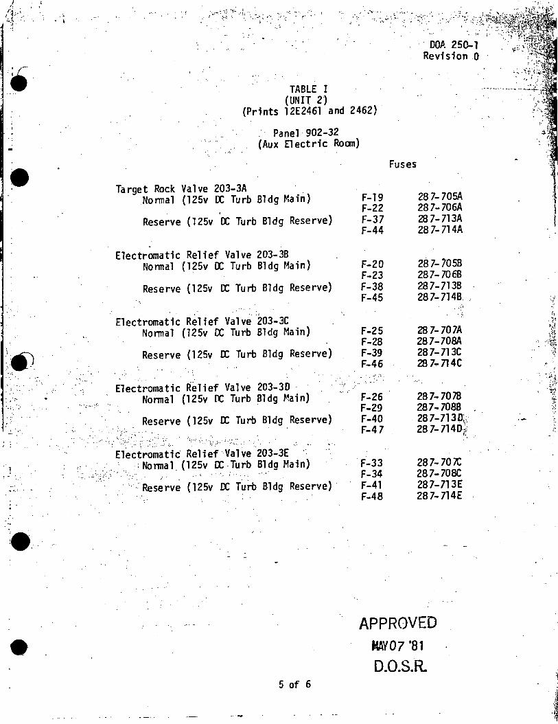
•
~\:A) . ~ -~ --;
..... . ..: .
. -. ·'. · ... :-. .':·
' !
i ! - -· ._
... .. . . ~ . •·
·" •. I
-: :': ''1• .;_.... • .... -.: ••.. ,-·-
,. !:.! ~ ·: ~. ~-· :. ~-· :·' ·-: . ~· .. ~ ..
·, ...
, •.. ,/, ..•... < "''_&~~};·:,,;
DOA 250-1 · Revision .o
TABLE I (UNIT 2)
(Prints 12E2461 and 2462)
.· · Panel· 902-32 _, (Aux Electric Roan)
. -~- .
Target Rock Valve 203-3A . . No nnal (l 25v OC Turb Bldg Ma in)
Reserve ( l 25v OC Turb Bldg Reserve)
Electromatic Relief Valve 203-3B Nonnal (l25v OC Turb Bldg Main)
Reserve {125v OC Turb Bldg Reserve)
Electromatic Relief Valve 203-3C Nonnal {125v OC Turb Bldg Main)
Reserve {l 25v OC Turb Bldg Reserve)
· .. : -· -~!,
Electromatic Relief Valve 203-30 · Nonnal (125v OC Turb Bldg Main)
·-·.
Reserve { 125v OC Tu rb Bldg Reserve) . ·-·~ -~ - .''
. :· :· . . . _ .. - . : .· .. -· ~:.-. ·~-:~:; ·.-~:· .: . ~-·. ·.· .. ·-·~=··.:-:·: ·::.::. .
Electromatic· Relief· Valve 203-3E ,: ·. _ .. , ,-; Nonnal {125v OC Turb Bldg Main) . ·.· .. _;. .:~ ~:... ,,.
· .. ··Reserve {125v OC Turb Bldg Reserve) ·
5 of 6
Fuses
F-19 28 7-705A F-22 287-706A
· F-37 28 7-713A F-44 287-714A
F-20 28 7- 7058 F-23 287-7068 F-38 287-713B F-45 287-7148.
. ,.,·J .. !-.
F-25 28 7-707A F-28 287-708A F-39 28 7-713C F-46 28 7-n4C - . - "".' :: . ..... .. ..
F-26 287-7078 F-29 287-7088 F-40 28 7-7130;.
<'
F-47 28 7-7140~; . ..
F-33 28 7- 70i'C F-34 287-70& F-41 287-713E F-48 28 7-714E
APPROVED MAY07 '81
0.0.S.R.
· .. - , ..
.•

~ ., ..• v. .. .I
I . .. . . .
•
..
,r~
-·
. ·.__ "' '
DOA 250-1 Revision 0
··TABLE II .. ··- ··- .... (UNIT ·3) :··-···· ~ ··~--···-·-. - .
(Prints 12E3461 ~nd 3462) ·
Panel 2203-32 (Second Floor of Reactor Building) .... ,,._.
Target Rock Valve 203-3A Nonnal {125v OC Turb Bldg Main)
Reserve (125v OC Turb Bldg Reserve).
Electromatic Relief Valve 203-3B Nonnal (125v OC Turb Bldg Main)
.. Reserve (125v DC Turb Bldg Reserve} . .
. ";·
Electrcxnatic Relief ValVe 203~3C· >:.· .. ·. Nonnal (125v OC Turb Bldg Mafo}
Reserve (125v OC Turb Bldg Reserve)
Electromatic Relief Valve 203-30 Nonnal (125v DC Turb Blda Main)
. . . . ...
., .. · -.. , _ .Reserve {125v OC Turb Bldg Reserve)
.. ;.~;:;· ?.~~.~~~. ~;.~]-: .. .; . > : .. ··, .... -. .. .... \ . ., .-. . . ·. ,. :•·· ... ··
· Electromatic Relief Valve 203-3E · · Nonnal (125v OC Turb Bldg Ma in)
.· .... _ ....... · .... ·:· .:- .. _·::· .... .::/: :-. .=/_···.;~-= .. : ..• :· .. : .
. ·Reserve (125v· OC Turt)~Bldg Reserve)
-" : .. . .
-. ....... : .... . ... · ....... ·· .
-~ ;:. .. "
Fuses
F-11 . 287-717A F-16 287-n BA F-1 287-713A F-6 28 7-714A
F-12 28 7-n.7B F-17 287-n as F-2 ':. 287-713B F-7 .. 28 7-n4B
. F-13 28 7-717C F-18 287'.-n ac F-3 287-n 3C F-8 28 7-714C
F-14 287-7170 F-19 28 7;-7180 F-4 287-7130 F-9 287-7140
· .. .- F-15 287-717E F-20 28 7- 718E
. F-5 . . 28 7- 713E
. F-10 .: ·; ~ , 28 7-714E
6 of 6 {FiNAW
APPROVED MAY07131
D.O.S.R.
- " . ~ .. ------· --- --·-----.
~.- .. : ._...__
: '.t. ,,
'l•l',
• . , • -~·r . . -: . ..
. · .
,. , '(,·
l!)· ..• '"' 1
•··
•.·.
TURBINE CONTROL VALVE FAIL OPEN
DOA 5650-3 · Revision 1 January 11, 1980
A. SYMPTOMS
l.
2.
3.
4.
5.
.. Drop in reactor pressure due to control valve opening wide.
A scan of valve position indicators on panel 902-7(903-7).
A scan of valve servo current meters on panel 902-7 {903-7) indicates signal to fa 11 ed valve. ·
HC ELECTRIC MALFUNCTION alann on panel 902-7(903-7).
Valve position recorder spike.
B. AUTCl1ATIC ACTIONS
l. Group 1 isolation and reactor. scram, if pressure decreases to 850 psig.
C. IMMEDIATE OPERATOR ACTIONS
. ~' .
. . - ~ ~ - .· -
l. Observe control valve position indication for detectio~·: of failed valve {both indicators and recorder). .,, ..
2. Check servo current meter to failed valve for·signal malfunction or servo/control valve malfunction.
3.
4.
5.
Notify Shift Supervisor.·
If unit load is greater than 500 MUe, operating control valves should canpensate for failed valve by throttling~'down avoiding a Group 1 low pressure isolation. If a Group 1 isolation.· does occur carry out DOA 1600-1. :::·.·
· Lower reactor power in steps in accordance with DGP 2-1, to ·a point where turbine can be manually tripped and reactor . scrammed before reaching 850 psig isolation. This is done to trip the turbine and scram reactor fran the lowest power · possible and to avoid a Group 1 isolation.
D. SUBSEQUENT OPERATOR ACTIONS
1. Fol low scram procedure DGP 2-3. ,
2. t1onitor reactor water level closely, using more than one level indication, and initiate corrective maintenance.
3. Shfft' Supervisor will prepare scram report ~nd also deviation report ·for the failed valve occurrence if applicable •
• . ~ APPROVED JAN l l 180
1 D.O.S.R.
.~i.'l . .. ~
.> ... ·.-:\,1-,
. ~· ~:E-."' ·i'.!
'~·J.
'" '1 ··~-·:
'

,..... (
~·
::~
·~ ..
•
E. DISCUSSION
DOA 5650-3 Revision 1
1. If unit is loaded to 500 MHe or less, control valve fail open may result in a Group 1 isolatiqn on low main steam line pressure {850 psig) and a reactor scram on 10% MSIV closure. Follow procedure DOA 1600-1 .for primary containment i.solation.
'.
2 (final)
.. 1
.,/'· . .,_ '· :
,.
APPROVED JAH 11 'BO
D.O.S.R.
t. '