
SMC guide to ATEX compliant productsca01.smcworld.com/catalog/SMC-HP-PDF/smc-atex-en-web.pdf5 Port...
124
SMC guide to ATEX compliant products P-E13-23A A
Transcript of SMC guide to ATEX compliant productsca01.smcworld.com/catalog/SMC-HP-PDF/smc-atex-en-web.pdf5 Port...

SMC guide to ATEX compliant products
P-E13-23A A

Directive 94/9/ECEquipment and Protective Systems intended for use in potentially Explosive Atmospheres
ATEX Directive
Outline of ATEX directive
SMC's products corresponding to ATEX DirectiveSMC's products which are within the scope of the ATEX Directive include electrical equipment and mechanical equipment such as pneumatic actuators (cylinders). SMC prepares pneumatic equipment for all industries compliant with the ATEX Directive to help our customers make a system corresponding to the Directive.
Certification ProcedureOur products are categorized as electrical and non-electrical products, and tested and certified as follows:
SMC's Support
ATEXCategory Certification method Certified by
Electrical products
Category 1
Category 2
Category 3
1. Technical file2. Quality audit3. Type approval test
Certification authorityCertification authorityCertification authority
1. Technical file2. Quality audit3. Type approval test
Certification authorityCertification authorityCertification authority
1. Technical file2. In-house production control
SMCSMC
Certification method Certified by
Non-electrical products
(Cylinder, rotary actuator, etc.)
1. Technical file2. Quality audit3. Type approval test
Certification authorityCertification authorityCertification authority
1. Technical file(to be stored in the certification authority)
2. Quality: In-house manufacturing control
SMC
SMC
1. Technical file2. In-house production control
SMCSMC
Zone 2Category 3
Zone 1Category 2
Zone 0Category 1
Continuously or for long periods>1000 hours/year
Occasionally10 to 1000 hours/year
Presence of the explosiveatmosphere
Equipment category
1
2
3 Rarely or for short periods<10 hours/year
Zone
0
1
2
Since 1st July 2003, equipment used in potentially explosive atmospheres within the EU is required to comply with the ATEX directive.
CE Marking and ATEXAll equipment within the scope of the Directive must bear the CE marking and comply with the directive's requirements. ATEX Directive incorporates conventional European standards for explosion-proof equipment.
Objective of the ATEX DirectiveMajor objective of the ATEX Directive is as follows: Preventing electrostatic discharge Preventing ignition likely to be caused by electrical sparks generated from friction, shock, and wear Preventing ignition under the influence of elevated temperatures due to friction, shock, and wear Concentrating on the duties of the manufacturers Certifying equipment to the ATEX directive by Zone/Category
Zone/Category classificationThe ATEX directive defines the categories of equipment and protective systems, which can be used in the corresponding zones as per the following table:
(Solenoid valve, auto switch, serial transmissionsystem, electro-pneumatic positioner, etc. )
1

5 Port Solenoid Valve: 52-SY5000/7000/90005 Port Solenoid Valve: 56-VQC1000/2000/4000
<Note for ordering ATEX compliant products>Some items may not be compliant with the ATEX Directive. For details, refer to How to Order.For Self Declaration of Conformity, refer to our sales representative.
INDEX
PneumaticSolenoid Valve
Integrated Type: For Input/Output: 56-EX250Decentralized Serial Wiring (GW system, 4 branches): 56-EX500
Serial Transmission System
Air Cylinder: 55-C76ISO Cylinder: 55-C85ISO Cylinder: 55-C95 (Bore sizes: 160, 200, 250)ISO Cylinder: 55-C96 (-C)ISO Cylinder: 55-CP96 (-C)IISO Cylinder: 55-C55Air Cylinder: 55-CG1Air Cylinder: 55-CS1Compact Cylinder: 55-CQ2Dual Rod Cylinder: 55-CXSMechanically Jointed Rodless Cylinder/Basic Type: 55-MY1B (-Z)Mechanically Jointed Rodless Cylinder/Slide Bearing Guide Type: 55-MY1MMechanically Jointed Rodless Cylinder/Linear Guide Type: 55-MY1H (-Z)
Rotary Actuator: 55-CRB1Rotary Actuator: 56-CRB1Rotary Actuator: 55-CRB2-ZRotary Actuator: 56-CRB2-ZRotary Actuator/Free Mount Type: 55-CRBU2-ZRotary Actuator/Free Mount Type: 56-CRBU2-ZCompact Rotary Actuator: 55-CRQ2Compact Rotary Actuator: 56-CRQ2
Booster Regulator: 56-VBA
Valve for Water and Chemical Base Fluids (2/3 port air operated valve): VCCAir Operated Chemical Valve/Threaded Type: 55-LVAProcess Pumps/Automatically Operated Type (Internal switching type) Air Operated Type (External Switching Type): 55-PA3000/5000Air Operated Type (External Switching Type): 56-PA3000/5000
Pneumatic-Pneumatic Positioner: 55-IP5000/5100Pneumatic-Pneumatic Positioner: 56-IP5000/5100Electro-Pneumatic Positioner: IP6000-X14/IP6100-X14Electro-Pneumatic Positioner: IP8000-X14/IP8100-X14Smart Positioner: 52-IP8001/52-IP8101Cylinder Positioner: 56-IP200
2-Color Display Digital Pressure Switch: 56-ISE70/75 (H)
Steam Valve: 56-VND
Solid State SwitchReed Switch
Air Cylinder
Rotary Actuator
Booster Regulator
Process Valve
Instrumentation Equipment
Pressure Switch
2 Port Valve for Fluid Control
Auto Switch
List of ATEX compliant products
1 2 3Category
Page no.
323
2930
33404345505455576064666768
6969
8889909192939495
96
97
99
100102
104105
106107108111112113
2 B

L
Barrier
01 F352 SY
ATEXcategory 2
Series579
52-SY500052-SY700052-SY9000
15 2 0
Type of actuation12345
2-position single2-position double3-position closed centre3-position exhaust centre3-position pressure centre
Piping type24
NilAF
Without barrierZ728.H
KFD0-SD2-Ex1.1065
Electrical entryL
LLTT
Plug connector typePlug connector with cover typeCable type
Lead wire length36
10152030
100
300 mm600 mm1000 mm1500 mm2000 mm3000 mm
10000 mm (Semi-standard)
BracketNilF1F2
Without bracketWith foot bracket Note 1)
With side bracket
Thread typeNilFNT
RcG
NPTNPTF
A, B port size (Body ported type)
Symbol01C4C6C8N3N7N902C8C10N9N110203C8C10C12N9N11
Port size Applicable series
52-SY5000
52-SY7000
52-SY9000
Nil0202030304
1/41/43/83/81/2
52-SY5000
52-SY7000
52-SY9000
Port size (Base mounted type)
Without sub-plate
Manual overrideNilDE
Non-locking push typePush-turn locking slotted typePush-turn locking lever type
Note 1) 2 position single solenoid valve only.
Note 2) 52-SY9000 has no bracket.
1/8One-touch fitting for ø4One-touch fitting for ø6One-touch fitting for ø8
One-touch fitting for ø5/32"One-touch fitting for ø1/4"One-touch fitting for ø5/16"
1/4One-touch fitting for ø8One-touch fitting for ø10
One-touch fitting for ø5/16"One-touch fitting for ø3/8"
1/43/8
One-touch fitting for ø8One-touch fitting for ø10One-touch fitting for ø12
One-touch fitting for ø5/16"One-touch fitting for ø3/8"
∗ L type has 300 mm and 600 mm only.
Note) Base mounted type only.
Note) One barrier per solenoid supplied.Additionally, when the barrier is selected, the barriers equivalent to the number of solenoids are included with the product.
Note) TT-type is connected to the terminal block.Cables other than the connected one cannot be used.
Nil
Body ported typeBase mounted type
R Note)
Internal pilotExternal pilot
Pilot type
II 2G Ex ia IIC T4...T5II 2G Ex ia IIC T6
Gb Ta−10°C to50°CGb Ta−10°C to 45°C0344
ATEX Compliant 5 Port Solenoid Valve
Series 52-SYHow to order
Symbol Port size Applicable series
3 D

Series
Coil temperature rise
Barrier input voltage (non hazardous area)
Coil rated voltage (hazardous area)
Intrinsically safe
Gas group
–10 to 45°C (No freezing)
–10 to 50°C (No freezing)
40°C less (at rated)
24 VDC (system rated voltage) at 1.1 W
12 VDC at 0.52 W
ia
IIC
IP30 (LL type : IP40)
IP65
52-SY5000 52-SY7000 52-SY9000Temperature class T6
Temperature class T4, T5
L type
TT type
Plug connector type
Cable typeResponse time
Type of actuation
2-position single2-position double3-position
52-SY500026 or less22 or less38 or less
52-SY700038 or less30 or less56 or less
52-SY900050 or less50 or less70 or less
Response time (ms) (0.5 MPa)
Manifold Specifications for 20 Type
Model
Applicable valve
Manifold style
1 (SUP) / 3/5 (EXH)
Valve stations
4/2 (A/B) Location
Port size
Manifold base weight W (g) n: Station
Single base / B mounting
Common SUP / Common EXH
2 to 20 (1)
Valve
1/4
SS5Y5-20
52-SY520
SS5Y7-20
52-SY720
1,3,5 (P,EA,EB) Port
4,2 (A,B) Port
1/8C4 (One-touch fitting for ø4)C6 (One-touch fitting for ø6)C8 (One-touch fitting for ø8)
1/4C8 (One-touch fitting for ø8)
C10 (One-touch fitting for ø10)
W = 36n + 6 W = 43n + 64
Manifold Specifications for 20 Type
Model
SS5Y5-20
SS5Y7-20
Port size Flow characteristics
1 4/2 (P A/B) 4/2 5/3 (A/B EA/EB)1,5,3
(P,EA,EB)
1/4
1/4
4,2
(A,B)
C8
C10
1.9
3.6
b
0.28
0.31
Cv
0.48
0.93
2.2
3.6
b
0.20
0.27
Cv
0.53
0.88
Manifold Specifications for 41 and 42 Type
Model
Applicable valve
Manifold style
1 (SUP) / 3/5 (EXH)
Valve stations
4/2 (A/B)Porting spec.
Port size
Manifold base weight W (g) n: Station
SS5Y5-41 SS5Y5-42 SS5Y7-42
52-SY740
Location
Direction
1,3,5 (P,EA,EB) Port
4,2 (A,B) Port
1/4 1/41/8
C6 (One-touch fitting for ø6)C8 (One-touch fitting for ø8)
1/4C6 (One-touch fitting for ø6)C8 (One-touch fitting for ø8)
1/4C10 (One-touch fitting for ø10)
W = 61n + 101 W = 79n + 127 W = 100n + 151
Manifold Specifications for 41 and 42 Type
Model
SS5Y5-41
SS5Y5-42
SS5Y7-42
Port size Flow characteristics
1 4/2 (P A/B) 4/2 5/3 (A/B EA/EB)1,5,3(P,EA,EB)
1/4
1/4
1/4
4,2(A,B)
C8
C8
C10
1.8
1.9
3.0
b
0.23
0.20
0.25
Cv
0.44
0.46
0.75
c[dm3/(s·bar)]c[dm3/(s·bar)]
c[dm3/(s·bar)]c[dm3/(s·bar)]
1.9
1.9
3.0
b
0.16
0.12
0.12
Cv
0.45
0.43
0.66
52-SY540
Standard SY manifolds Types 20, 41, 42 are used for 52-SY valves.
Ambient and fluidtemperature
Protectionrating
Note) Impact resistance: No malfunction resulted from the impact test using a drop impact tester. The test were performed one time each in the axial and right angle directions of the main valve and armature, in both energized and de-energized states (Valve in the initial stage).
Vibration resistance: No malfunction occurred in a one-sweep test between 8.3 and 2000Hz. The test was performed for both energized and de-energized states in the axial and right angle directions of the main valve and armature (valve in the initial stage).
Note 1) For more than 10 stations (more than 5 stations in case of SS5Y7), supply pressure to P port on both sides and exhaust from EA/EB port on both side.
Note 2) 52-SY920 valve are not available with manifold as standard.
Note 1) For more than 10 stations (more than 5 stations in case of SS5Y7), supply pressure to P port on both sides and exhaust from EA/EB port on both side.
Note 2) 52-SY940 valve are not available with manifold as standard.Note 3) 52-SY series are not available with resin type manifold (45 type).
Single base / B mounting
Common SUP / Common EXH
2 to 20 (1)
Base
Side
Safety Instructions
Note 1) According to dynamic performance test JIS B8375-1981.Note 2) Response time when barriers were combined with a valve.
System A: Valve + Z728.HF: Valve + KFD0-SD2-Ex1.1065
1) This product is not suitable for Zone 0. The suitable zones are Zones 1 and 2.2) SMC-TAS and TAV Series, antistatic tubing, are available if required.3) The solenoid valve has polarity. Confirm the correct polarity by observing the
color of the lead aires. if the polarity is reversed, the barrier may be damaged.4) Confirm that the solenoid input voltage at the lead wires is 10.8 VDC (min).5) This product must be connected to an appropriate barrier (ATEX compliant
product), or a certified intrinsically safe circuit, with the following maximum values.
Ui = 28 Vli = 225 mA (resistively limited)Pi = 1 WCi = 0 nFLi = 0 mH
Note) Values for 5 stations manifold with a 2 position single type valve.
Note) Values for 5 stations manifold with a 2 position single type valve.
Series 52-SYATEX Compliant 5 Port Solenoid Valve
Specifications
4 C

1214
.7
L 104
Max.10
L 120.8
ø5.
9ø
4.1
111.
8
32.5 10.5
40
14.7
47
4.538
2922
16.6
1.2
109.1L
(45)
ø1.
55
32.3
14.7
(1.2)
(11.7)
16.7
(40.
2)
(36.
7)
(37)
36
16.2
21
40
65
(32.3)
32.5
(20)
11.6
0.8
15
1.6
22.6
20.5
27.2
0.75 mm2
0.3 mm2
0.3 mm2
EBPEA
AB
2-position singleL plug connector (L)52-SY5120-L-01 (-F2) In case with foot bracket
52-SY5120-L-01-F1
L plug connector with cover (LL)52-SY5120-LL-01 (-F2)
Cable type (TT)52-SY5120-TT-01 (-F2)
Insulation: Red (+)
Insulation: Black (–)
2 x M3 x 0.5 Threads depth 3.5(For bracket mounting)
2 x ø3.2(Mounting holes for manifold)
2 x 1/8"A (4), B (2) port(2 x ø3.2 Mounting holes)
44 (
For
E ty
pe)
(Lead wire length)
(Lead wire length)
(Lead wire length)
2 x ø2.2(Positioning for manifold gasket)
3 x 1/8"P (1), EA (5), EB (3) port
Manual override
2 x ø3.2(Mounting holes)
Insulation: Red (+)Insulation: Black (–)
Lead wire markingNo.1 (+), No.2 (–)
Dimensions
Series 52-SY5000ATEX Compliant Body Ported Type
5
(88.5)
(71.7)
14.7
12
(76.8)
L 153.6
11.6
16.2
36
65.414
.7
40
(11.7)
(1.2)
37
(40.
2)
20.5 32
.5(3
6.7)
0.8
(20)15
1.6
27.2
(45)
ø1.
55
16.7
22.6
177
143.4
ø5.
9ø
4.1
Max.10
L
0.75 mm2
0.3 mm2
EBPEA
A
B
0.3 mm2
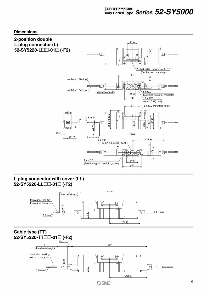
2-position doubleL plug connector (L)52-SY5220-L-01 (-F2)
L plug connector with cover (LL)52-SY5220-LL-01 (-F2)
Cable type (TT)52-SY5220-TT-01 (-F2)
Insulation: Red (+)
Insulation: Black (–)
2 x M3 x 0.5 Threads depth 3.5(For bracket mounting)
2 x ø3.2(Mounting holes for manifold) 2 x 1/8"A (4), B (2) port
(2 x ø3.2 Mounting holes)
Manual override
(Lead wire length)
(Lead wire length)
L(Lead wire length)
44 (F
or E
type
)
3 x 1/8"P (1), EA (5), EB (3) port
2 x ø2.2(Positioning for manifold gasket)
Insulation: Red (+)Insulation: Black (–)
Lead wire markingNo.1 (+), No.2 (–)
Series 52-SY5000ATEX Compliant Body Ported Type
Dimensions
6

101.1
84.3
14.7
12
189.6
156
32.7 45.3
(89.4)
32.5
(36.
7)
89.4
L 166.2
11.6
16.2
36
14.7
40
(1.2)
(37)
(40.
2)
20.5
0.8
(20)15
1.6
27.2
(45)
ø1.
55
16.7
22.6
ø5.
9ø
4.1
Max.10
L
0.3 mm2
EBPEA
AB
0.75 mm2
0.3 mm2
3-position closed centre/exhaust centre/pressure centreL plug connector (L)
L plug connector with cover (LL)
52-SY5420-LL-01 (-F2)3
5
Cable type (TT)
52-SY5420-TT-01 (-F2)3
5
2 x M3 x 0.5 Threads depth 3.5(For bracket mounting)
Insulation: Red (+)
Insulation: Black (–)
Manual override2 x ø3.2(Mounting holes for manifold)
2 x 1/8"A (4), B (2) port
(2 x ø3.2 Mounting holes)44
(For
E ty
pe)
(Lead wire length)
(Lead wire length)
L(Lead wire length)
3 x 1/8"P (1), EA (5), EB (3) port
2 x ø2.2(Positioning for manifold gasket)
Insulation: Red (+)Insulation: Black (–)
Lead wire markingNo.1 (+), No.2 (–)
Dimensions
Series 52-SY5000ATEX Compliant Body Ported Type
52-SY5420-L-01 (-F2)3
5
7

2-position singleL plug connector (L)52-SY7120-L-02 (-F2)
14.7
12
135
ø5.
9
L
Max.10
L 118.2
ø4.
1
19.8
28 38
46 5.5
57
40
14.7
1.2
125
39.5 13
123.3L
42
20
(52)
14.7
(14)
1.2
40
(66)
39.4
(49.
5)
(42.
5)
40
24.5
7
29.420
(23.
9)
36
2 0.9
18
13.6
79.2
(39.4)
0.75 mm2
0.3 mm2
0.3 mm2
B
A
EBPEA
In case with foot bracket52-SY7120-L-02-(F1)
L plug connector with cover (LL)52-SY7120-LL-02 (-F2)
Cable type (TT)52-SY7120-TT-02 (-F2)
2 x M4 x 0.7 Threads depth 6.5(For bracket mounting)
Manual override
Insulation: Red (+)
Insulation: Black (–)
2 x ø4.2(Mounting holes for manifold)
2 x 1/4"A (4), B (2) port
(2 x ø4.2 Mounting holes)
44 (F
or E
type
)
1/4"P (1) port2 x 1/8"
EA (5), EB (3) port
(Lead wire length)
2 x ø2.2(Positioning for manifold gasket)
Insulation: Red (+)Insulation: Black (–)
(Lead wire length)
Lead wire markingNo.1 (+), No.2 (–)
(Lead wire length)
Dimensions
Series 52-SY7000ATEX Compliant Body Ported Type
8

2-position doubleL plug connector (L)52-SY7220-L-02 (-F2)
(78.8)
Max.10
L 191.2
(95.6)
ø5.
9ø
4.1
L 157.6
7
20
(1.2)
(14)
(23.
9)
0.9
18(83.9)
79.6
ø1.
55
L 167.8
2
42
20
(52)
14.7
14.7
12
40
(66)
(49.
5)
(42.
5)
40
24.5
36
13.6
0.75 mm2
0.3 mm2
0.3 mm2
B
A
EBPEA
L plug connector with cover (LL)52-SY7220-LL-02 (-F2)
Cable type (TT)52-SY7220-TT-02 (-F2)
2 x M4 x 0.7 Threads depth 6.5(For bracket mounting)
2 x ø4.2(Mounting holes for manifold)2 x 1/4"A (4), B (2) port
(2 x ø4.2 Mounting holes)
Manual overrideInsulation: Red (+)
Insulation: Black (–)
44 (F
or E
type
)
(Lead wire length)
(Lead wire length)
(Lead wire length)
1/4"P (1) port
2 x 1/8"EA (5), EB (3) port
2 x ø2.2(Positioning for manifold gasket)
Insulation: Red (+)Insulation: Black (–)
Lead wire markingNo.1 (+), No.2 (–)
Dimensions
Series 52-SY7000ATEX Compliant Body Ported Type
9

3-position closed centre/exhaust centre/pressure centreL plug connector (L)
52-SY7420-L-02 (-F2)
52.839.8
91.8
Max.10L 204.2
108.6
ø5.
9ø
4.1
L 170.6
7
20
(1.2)
(14)
(23.
9)0.
918
96.9
ø1.
55
L 180.8
2
42
20
(52)
14.7
14.7
12
40
(66)
(49.
5)
(42.
5)
40
24.5
36
13.6
0.75 mm2
0.3 mm2
0.3 mm2
B
A
EBPEA
3
5
L plug connector with cover (LL)
52-SY7420-LL-02 (-F2)3
5
Cable type (TT)
52-SY7420-TT-02 (-F2)3
5
2 x M4 x 0.7 Threads depth 6.5(For bracket mounting)
Manual overrideInsulation: Red (+)
Insulation: Black (–)
2 x ø4.2(Mounting holes for manifold)
2 x 1/4"A (4), B (2) port
(2 x ø4.2 Mounting holes)
(Lead wire length)
(Lead wire length)
(Lead wire length)
44 (F
or E
type
)
1/4"P (1) port
2 x 1/8"EA (5), EB (3) port
2 x ø2.2(Positioning for manifold gasket)
Insulation: Red (+)Insulation: Black (–)
Lead wire markingNo.1 (+), No.2 (–)
Dimensions
Series 52-SY7000ATEX Compliant Body Ported Type
10

2-position singleL plug connector (L)52-SY9120-L- 02
03
Max.10
L 165.1
ø4.
1
16.7
14
L 148.3
36.6
153.4
ø1.
55
L
(12)
42
10
46 (F
or E
type
)
24.9 43.85
56.3
18.4
109.3
6.5 (56.3)
64.2
33.6
51.5
49.8
230.
50.
5
16.7
0.75 mm2
0.3 mm2
0.3 mm2
B2A4
3EB1P5EA
L plug connector with cover (LL)52-SY9120-LL- 02
03
Cable type (TT)52-SY9120-TT- 02
03
Insulation: Red (+)
Insulation: Black (–)
Manual override
3 x ø3.2(Mounting holes for manifold)
2 x 1/4", 3/8"4 (A), 2 (B) port
(Lead wire length)
(Lead wire length)
2 x ø4.4(Mounting holes)
3 x 1/4"1 (P), 3 (EB), 5 (EA) port
Lead wire markingNo.1 (+), No.2 (–)
(Lead wire length)
Insulation: Red (+)Insulation: Black (–)
Dimensions
Series 52-SY9000ATEX Compliant Body Ported Type
11

2-position doubleL plug connector (L)52-SY9220-L- 02
03
217.6
184
106
194.2
97.1
Max.10
L
ø4.
1
16.7
14
L
36.6
ø1.
55
L
(12)
42
10
46 (F
or E
type
)
24.9
18.4
6.5
64.2
33.6
51.5
49.8
230.
50.
5
16.7
0.75 mm2
0.3 mm2
0.3 mm2
2B4A
3EB1P5EA
L plug connector with cover (LL)52-SY9220-LL- 02
03
Cable type (TT)52-SY9220-TT- 02
03
Insulation: Red (+)
Insulation: Black (–)
Manual override
3 x ø3.2(Mounting holes for manifold)
2 x 1/4", 3/8"4 (A), 2 (B) port
(Lead wire length)
2 x ø4.4(Mounting holes)
3 x 1/4"1 (P), 3 (EB), 5 (EA) port
Insulation: Red (+)Insulation: Black (–)
(Lead wire length)
(Lead wire length)
Lead wire markingNo.1 (+), No.2 (–)
Dimensions
Series 52-SY9000ATEX Compliant Body Ported Type
12

(108.5)
(125.3)
234.1
201
123
210.7
113.6
Max.10
L
ø4.
1
16.7
14
L
36.6
ø1.
55
L
(12)
42
10
46 (F
or E
type
)
24.9
18.4
6.5
64.2
33.6
51.5
49.8
230.
50.
5
16.7
0.75 mm2
0.3 mm2
0.3 mm2
B2A4
3EB1P5EA
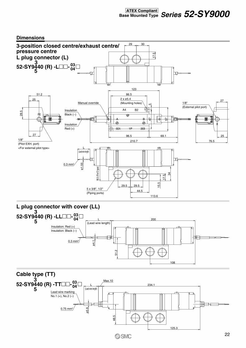
3-position closed centre/exhaust centre/pressure centreL plug connector (L)
52-SY9420-L- 0203
3
5
L plug connector with cover (LL)
52-SY9420-LL- 0203
3
5
Cable type (TT)
52-SY9420-TT- 0203
3
5
InsulationRed (+)
InsulationBlack (–)
Manual override
3 x ø3.2(Mounting holes for manifold)
2 x 1/4", 3/8"4 (A), 2 (B) port
(Lead wire length)
(Lead wire length)
(Lead wire length)
2 x ø4.4(Mounting holes)
3 x 1/4"1 (P), 3 (EB), 5 (EA) port
Insulation: Red (+)Insulation: Black (–)
Lead wire markingNo.1 (+), No.2 (–)
Dimensions
Series 52-SY9000ATEX Compliant Body Ported Type
13

2-position singleL plug connector (L)52-SY5140 (R) -L-02
34.5
37.2
Max.10
L 120.8
ø5.
9
L 104
ø4.
1
17.5
65
109.1
4.356
35
4
60.3
8.34837.2
L
66.5
(For
E ty
pe)
62.5
17
ø1.
55
17
15.5 15.5
19
22
9.5
28
18 18
9.518
(Lead wire length)
(Lead wire length)
0.75 mm2
0.3 mm2
0.3 mm2
A B
EP
XP EBEA
BA
L plug connector with cover (LL)52-SY5140 (R) -LL-02
Cable type (TT)52-SY5140 (R) -TT-02
2 x ø4.3(Mounting holes)
Manual override
InsulationRed (+)
InsulationBlack (–)
5 x 1/4"(Piping ports)
(Lead wire length)
M5 x 0.8(External pilot port)
M5 x 0.8(Pilot EXH. port)<For external pilot type>
Insulation: Red (+)Insulation: Black (–)
Lead wire markingNo.1 (+), No.2 (–)
Dimensions
Series 52-SY5000ATEX Compliant Base Mounted Type
14

2-position doubleL plug connector (L)52-SY5240 (R) -L-02
L plug connector with cover (LL)52-SY5240 (R) -LL-02
Cable type (TT)52-SY5240 (R) -TT-02
153.6
L
ø1.
55
(71.7)
(88.5)
143.4
Max.10
177L
ø5.
9
L
ø4.
1
62.5
4
17.5
65.4
17.5
56
35
4
48
37.2
66.5
(For
E ty
pe)
1717
15.5 15.5
19
22
9.5
28
18 18
9.5
18
0.3 mm2
0.75 mm2
0.3 mm2
AB
PE XP EBEA
BA37
.234
.5
2 x ø4.3(Mounting holes)
Manual override
Insulation: Red (+)
Insulation: Black (–)
M5 x 0.8(External pilot port)
M5 x 0.8(Pilot EXH. port)<For external pilot type>
(Lead wire length)
(Lead wire length)
5 x 1/4"(Piping ports)
Insulation: Red (+)Insulation: Black (–)
Lead wire markingNo.1 (+), No.2 (–)
(Lead wire length)
Dimensions
Series 52-SY5000ATEX Compliant Base Mounted Type
15

3-position closed centre/exhaust centre/pressure centreL plug connector (L)
52-SY5440 (R) -L-02
L plug connector with cover (LL)
52-SY5440 (R) -LL-02
Cable type (TT)
52-SY5440 (R) -TT-02
84.3
89.4
44.1
166.2
L
ø1.
55
156L
ø4.
1
62.5
4
17.5
78
17.5
56
35
4
48
37.2
66.5
(For
E ty
pe)
1717
15.5 15.5
19
22
9.5
28
18 18
9.5
18
0.3 mm2
0.3 mm2
AB
EP
P EBEA
BA
101.1
Max.10
189.6L
ø5.
90.75 mm2
3
5
3
5
X
37.2
34.5
M5 x 0.8(Pilot EXH. port)<For external pilot type>
Insulation: Red (+)
Insulation: Black (–)
2 x ø4.3(Mounting holes)
Manual overrideM5 x 0.8(External pilot port)
(Lead wire length)
5 x 1/4"(Piping ports)
Insulation: Red (+)Insulation: Black (–)
(Lead wire length)
Lead wire markingNo.1 (+), No.2 (–)
(Lead wire length)
Dimensions
Series 52-SY5000ATEX Compliant Base Mounted Type
3
5
16

2-position singleL plug connector (L)52-SY7140 (R) -L-
L plug connector with cover (LL)52-SY7140 (R) -LL-
Cable type (TT)52-SY7140 (R) -TT- Max.10
L 135
ø5.
9
L 118.2
ø4.
1ø
1.55
4
23
71.2
(For
E ty
pe)
67.2
L
21.5
41.7
123.3
6.4
10.4
79.2
69
22.5
38 46
21
21
21.5
13.5
21
61
26.5
13.5
11.5
33
20.5 20.5
(Lead wire length)
(Lead wire length)
0.75 mm2
0.3 mm2
0.3 mm2
BA
P
BA
EBEA
PE
X
41.7
39
Insulation: Red (+)
Insulation: Black (–)
M5 x 0.8(Pilot EXH. port)<For external pilot type>
Manual override M5 x 0.8(External pilot port)
2 x ø4.3(Mounting holes)
(Lead wire length)
5 x 3/8", 1/4"(Piping ports)
Insulation: Red (+)Insulation: Black (–)
Lead wire markingNo.1 (+), No.2 (–)
0203
0203
0203
Dimensions
Series 52-SY7000ATEX Compliant Base Mounted Type
17

2-position doubleL plug connector (L)52-SY7240 (R) -L-
L plug connector with cover (LL)52-SY7240 (R) -LL-
Cable type (TT)52-SY7240 (R) -TT-
ø5.
9
Max.10L
(95.6)
(78.8)
191.2
ø4.
1
L 157.6
13.5
26.5
11.5
20.5 20.5
33
ø1.
55
L
71.2
(For
E typ
e)
21
23
41.7
21.5
21.5
67.2
23
21
167.8
79.6
69
384
46
461
13.5
21 22.5
0.75 mm2
0.3 mm2
0.3 mm2
EP
BA
P
BA
EBEA
X
41.7
39
M5 x 0.8(Pilot EXH. port)<For external pilot type>
Insulation: Red (+)
Insulation: Black (–)
Manual override
2 x ø4.3(Mounting holes)
M5 x 0.8(External pilot port)
(Lead wire length)
5 x 3/8", 1/4"(Piping ports)
Insulation: Red (+)Insulation: Black (–)
(Lead wire length)
Lead wire markingNo.1 (+), No.2 (–)
(Lead wire length)
0203
0203
0203
Dimensions
Series 52-SY7000ATEX Compliant Base Mounted Type
18

3
5
3
5
3-position closed centre/exhaust centre/pressure centreL plug connector (L)
52-SY7440 (R) -L-
L plug connector with cover (LL)
52-SY7440 (R) -LL-
Cable type (TT)
52-SY7440 (R) -TT-
96.9
44.1
91.8
ø4.
1
L 170.6
13.5
26.5
11.5
20.5 20.5
33
ø1.
55
L
71.2
(For
E typ
e)
21
23
41.7
21.5
21.5
67.2
23
21
180.8
92.6
69
384
46
461
13.5
21 22.5
0.3 mm2
0.3 mm2
EP
BA
P
BA
EBEA
X
ø5.
9
Max.10L
108.6
204.2
0.75 mm2
3
5
41.7
39
M5 x 0.8(Pilot EXH. port)<For external pilot type>
InsulationRed (+)
InsulationBlack (–)
Manual override
2 x ø4.3(Mounting holes)
M5 x 0.8(External pilot port)
(Lead wire length)
5 x 3/8", 1/4"(Piping ports)
Insulation: Red (+)Insulation: Black (–)
(Lead wire length)
Lead wire markingNo.1 (+), No.2 (–)
(Lead wire length)
0203
0203
0203
Dimensions
Series 52-SY7000ATEX Compliant Base Mounted Type
19

2-position singleL plug connector52-SY9140 (R) -L- 03
04
L plug connector with cover (LL)52-SY9140 (R) -LL- 03
04
Cable type (TT)52-SY9140 (R) -TT- 03
04
11.8
153.4
16.8
109.3
L 148.3
ø4.
1
ø1.
55
L
80.5
(For
E ty
pe)
51.2
76.5
28.5
515
.5
17.5 34
29.5 29.5
44.5
25
86.5
5747
96.527 25
27
17.5
29 30
0.3 mm2
0.3 mm2
A B
X
A4 B2
3EB1P5EA
PE
Max.10L 165.1
ø5.
90.75 mm2
51.2
48.5
(Lead wire length)
(Lead wire length)
(Lead wire length)
Dimensions
2 x ø5.4(Mounting holes)Manual override 1/8"
(External pilot port)InsulationBlack (−)
InsulationRed (+)
1/8"(Pilot EXH. port)<For external pilot type>
5 x 3/8", 1/2" (Piping ports)
Insulation: RedInsulation: Black
Lead wire markingNo.1 (+), No.2 (−)
Series 52-SY9000ATEX Compliant Base Mounted Type
20

2-position doubleL plug connector (L)52-SY9240 (R) -L- 03
04
L plug connector with cover (LL)52-SY9240 (R) -LL- 03
04
Cable type (TT)52-SY9240 (R) -TT- 03
04
(108.8)
217.6
(92)
184
76.5
27
25
194.2
106
Max.10L
L
ø4.
1
ø5.
9ø
1.55
L
80.5
(For
E typ
e)
51.2
28.5
515
.5
17.5 34
29.5 29.5
44.5
25
86.5
5747
96.527
17.5
29 30
0.3 mm2
0.75 mm2
0.3 mm2
A B
X
4A 2B
3EB1P5EA
PE51
.248
.5
(Lead wire length)
(Lead wire length)
(Lead wire length)
Dimensions
Manual override2 x ø5.4(Mounting holes) 1/8"
(External pilot port)InsulationBlack (−)
InsulationRed (+)
1/8"(Pilot EXH. port)<For external pilot type>
5 x 3/8", 1/2"(Piping ports)
Insulation: Red (+)Insulation: Black (−)
Lead wire markingNo.1 (+), No.2 (−)
Series 52-SY9000ATEX Compliant Base Mounted Type
21
3-position closed centre/exhaust centre/pressure centreL plug connector (L)
L plug connector with cover (LL)
52-SY9440 (R) -LL- 0304
Cable type (TT)
113.6
69.1
76.5
27
25
210.7
123
ø1.
55
L
80.5
(For
E typ
e)51.2
28.5
5
15.5
17.5 34
29.5 29.5
44.5
25
86.5
5747
96.527
17.5
29 30
0.3 mm2
A B
A4 B2
3EB1P5EA
PE
108
200L
ø4.
10.3 mm2
125.3
234.1Max.10
L
ø5.
90.75 mm2
52-SY9440 (R) -L- 0304
3
5
3
5
52-SY9440 (R) -TT- 0304
3
5
X
51.2
48.5
(Lead wire length)
(Lead wire length)
(Lead wire length)
Dimensions
Manual override2 x ø5.4(Mounting holes) 1/8"
(External pilot port)
InsulationRed (+)
InsulationBlack (−)
1/8"(Pilot EXH. port)<For external pilot type>
5 x 3/8", 1/2"(Piping ports)
Insulation: Red (+)Insulation: Black (−)
Lead wire markingNo.1 (+), No.2 (−)
Series 52-SY9000ATEX Compliant Base Mounted Type
22

Series 56-VQC1000
ATEX Compliant 5 Port Solenoid Valve
ATEX category 3
VV5QC 1 1 08 TD0
COM
Kit designation/Electrical entry/Cable length
F T...... /M S Kit
−COM.N
56 N /C3
Manifold with M- or T- kitII 3G Ex nA II B T5 Gc X
II 3D Ex tc III C T85°C Dc X IP67–10°C ≤ Ta ≤ +50°C
Special condition X "Protect from Impact"
Series 56-VQC1000
Base mounted plug-in
Stations01
…
1 station
…
The minimum or maximum number of stations differs depending on the electrical entry. (Refer to “Electrical Entry/Cable Length”)
Cylinder port sizeC3C4C6M5CML3L4L6L5LMB3B4B6B5BM
With ø3.2 One-touch fittingWith ø4 One-touch fittingWith ø6 One-touch fittingM5 threadMixed sizes and with port plugTop ported elbow, with ø3.2 One-touch fittingTop ported elbow, with ø4 One-touch fittingTop ported elbow, with ø6 One-touch fittingM5 threadElbow port, mixture sizesBottom ported elbow, with ø3.2 One-touch fittingBottom ported elbow, with ø4 One-touch fittingBottom ported elbow, with ø6 One-touch fittingM5 threadElbow for bottom port, mixture sizes
OptionNil None
All stations with back pressure check valveWith DIN rail (Rail length: Standard)With DIN rail (Rail length: Special)Special wiring specifications (Except double wiring)With name plateExternal pilot
BD
DKNR
M Kit(Circular connector kit)
MD0MD1MD2MD3
Circular connector kit (26P) without cableCircular connector kit (26P) with 1.5 m cableCircular connector kit (26P) with 3 m cableCircular connector kit (26P) with 5 m cable
1 to 12stations
(Up to 24solenoid coils)
26 pins
T Kit(Terminal block box kit)
TD0 Terminal block box kit1 to 10 stations
(Up to 20 solenoid coils)
S Kit(Serial transmission kit: EX500 gateway type)
SDA2 DeviceNet, PROFIBUS DP1 to 8 stations
(Up to 16 solenoid coils)
SI unit: 56-EX500
Contact SMC for 56-EX250 with Profibus DP
All other specifications are the same as the standard products Series VQC. For details, refer to the WEB catalog or Best Pneumatics No. 1.
How to Order Manifold
Note) A separate gateway unit and communication cable are required.
Note) Refer to Serial transmission system on page 30 for the S kit.
∗ The maximum number of stations displayed in parentheses is applied to the special wiring specifications. (Option “-K”)The maximum number of stations is determined by the total number of solenoids. (Single solenoid type: 1 point, Double solenoid type: 2 points)Make sure that the total number of solenoids does not exceed the maximum number of stations. Additionally, when combining with option parts, make sure that the maximum number of stations is not exceeded.
23

VQC 1 1 0 5056 ATEX category 3
Series 56-VQC1000
Type of actuation1
2
345
ANote)
BNote)
CNote)
Note) For rubber seal type only.
Metal sealRubber seal
01
Seal type
FunctionStandard type (1W)External pilot
NilR Note)
Coil voltage24 VDC5
Manual overrideNil: Non-locking push type (Tool required)
B: Locking type (Tool required)
C: Locking type (Manual)
D: Slide locking type (Manual)
Ground terminalBlanking plate assembly
Individual SUP spacer
Individual EXH spacer
SUP block plate
EXH block plate
EXH block base assembly
Back pressure check valve assembly [-B]
Port plug
2 stations matching fitting assembly
Elbow fitting assembly
Port plug
Blanking plug
DIN rail mounting bracket [-D]
Name plate [-N]
56-VQC1000VVQ1000-10A-1
VVQ1000-P-1-C6
VVQ1000-R-1-C6
VVQ1000-16A
VVQC1000-19A--VVQ1000-18A
VVQ0000-58A
VVQ1000-52A-C8
VVQ1000-F-L-VVQ0000-58A
KQ2P-VVQ1000-57A(-S)
VVQ1000-N-
—
Manifold Option
2-position single2-position double (Metal)2-position double (Rubber)3-position closed centre3-position exhaust centre3-position pressure centre4-position dual 3 port valve (A)4-position dual 3 port valve (B)4-position dual 3 port valve (C)
Note) Please refer to standard catalogues for details.Do not use options other than specified in this table.Only these standard parts without "56-" prefix can be used.
Note) ''56-'' solenoid valve should be installed in ''56-VV5QC11'' manifold.Power consumption when starting is 1W, when maintaining 0.35W.''56-VQC'' solenoid valve has no polarity"
How to Order Valves
Series 56-VQC1000ATEX Compliant Base-Mounted Type/Plug-in Unit
Note) Not available for dual 3 port.
24

Series 56-VQC2000
ATEX category 3
VV5QC 2 1 08
Series 56-VQC2000
TD0
Base-Mounted Plug-in
F T/M S Kit56 N /C4
Stations01 1 station
The minimum or maximum number of stations differs depending on the electrical entry (refer to “Electrical entry/Cable length”).
Cylinder port sizeC4C6C8CML4L6L8LMB4B6B8BM
With ø4 One-touch fittingWith ø6 One-touch fittingWith ø8 One-touch fittingMixed sizes and with port plugTop ported elbow With ø4 One-touch fittingTop ported elbow With ø6 One-touch fittingTop ported elbow With ø8 One-touch fittingElbow port, mixture sizesBottom ported elbow With ø4 One-touch fittingBottom ported elbow With ø6 One-touch fittingBottom ported elbow With ø8 One-touch fittingElbow for bottom port, mixture sizes
OptionsNil None
All stations with back pressure check valveWith DIN rail (rail length: standard)With DIN rail (rail length: special)Special wiring specifications (except for double wiring)With name plateExternal pilotBranched P and R ports on U side
BD
DKNRT
Kit designation/Electrical entry/Cable length
M Kit(Multiple connector kit)
MD0MD1MD2MD3
Multiple connector kit (26P) without cableMultiple connector kit (26P) with 1.5 m cableMultiple connector kit (26P) with 3 m cableMultiple connector kit (26P) with 5 m cable
1 to 12stations
(Up to 24solenoid coils)
26 pins
T Kit(Terminal block box kit)
TD0 Terminal block box kit1 to 10 stations
(Up to 20 solenoid coils)
S Kit(Serial transmission kit: EX500 gateway type)
SDA2 DeviceNet, PROFIBUS DP1 to 8 stations
(Up to 16 solenoid coils)
SI unit: 56-EX500
Contact SMC for 56-EX250 with Profibus DP.
All other specifications are the same as the standard products Series VQC.For details, refer to the WEB catalog or Best Pneumatics No. 1.
Manifold with M- or T- kitII 3G Ex nA II B T5 Gc X
II 3D Ex tc III C T85°C Dc X IP67–10°C ≤ Ta ≤ +50°C
Special condition X "Protect from Impact"
COM.−COM.N
How to Order Manifolds
ATEX Compliant
5 Port Solenoid Valve
......
… …
Note) A separate gateway unit and communication cable are required.
Note) Refer to Serial transmission system on page 30 for the S kit.
∗ The maximum number of stations displayed in parentheses is applied to the special wiring specifications. (Option “-K”)The maximum number of stations is determined by the total number of solenoids. (Single solenoid type: 1 point, Double solenoid type: 2 points)Make sure that the total number of solenoids does not exceed the maximum number of stations. Additionally, when combining with option parts, make sure that the maximum number of stations is not exceeded.
25

ø2OFF
ON
11 mm
ø4.2
ø4.2
VQC 2 1 0 5056 ATEX category 3
Series 56-VQC2000
Metal sealRubber seal
01
Seal type
FunctionStandard type (1W)External pilot
NilR Note)
Coil voltage24 VDC5
VVQ2000-10A-1
VVQ2000-P-1-C8
VVQ2000-R-1-C8
VVQ2000-16A
VVQ2000-19A
VVQ2000-18A
VVQ1000-58A
VVQ2000-52A-C10
VVQ2000-F-L-VVQ1000-58A
KQ2P-VVQ2000-57A (-S)
VVQ2000-N-
—
Nil: Non-lockingpush type (Tool required)
B: Locking type(Tool required)
C: Locking type(Manual)
Manual override
D: Slidelocking type (Manual)
Name
Blanking plate assembly
Individual SUP spacer
Individual EXH spacer
SUP block plate
EXH block plate
EXH block base assembly
Back pressure check valve assembly [-B]
Port plug
Dual flow fitting assembly
Elbow fitting assembly
Port plug
Blanking plug
DIN rail mounting bracket [-D]
Name plate [-N]
56-VQC2000
Manifold Options
Type of actuation1
2
345
ANote)
BNote)
CNote)
Note) For rubber seal type only.
2-position single2-position double (Metal)2-position double (Rubber)3-position closed centre3-position exhaust centre3-position pressure centre4-position dual 3-port valve (A)4-position dual 3-port valve (B)4-position dual 3-port valve (C)
Notes) : Please refer to standard catalogues for details.Do not use options other than specified in this table.Only these standard parts without "56-" prefix can be used.
Note) ''56-'' solenoid valve should be installed in ''56-VV5QC21'' manifold. Power consumption when starting is 1 W, when maintaining 0.35 W. "56-VQC" solenoid valve has no polarity.
How to Order Valves
Series 56-VQC2000ATEX Compliant Base-Mounted Type/Plug-in Unit
Note) Not available for dual 3 port.
26

ATEX category 3
VV5QC 4 1 08
Series 56-VQC4000
TD0
Base-Mounted Plug-in
F T⋅⋅⋅⋅⋅⋅ /M S Kit56 02
Thread typeNilFNT
RcGNPTNPTF
N /
Kit designation/Electrical entry/Cable length
M Kit(Multiple connector kit)
MD0MD1MD2MD3
Multiple connector kit (26P) without cableMultiple connector kit (26P) with 1.5 m cableMultiple connector kit (26P) with 3 m cableMultiple connector kit (26P) with 5 m cable
1 to 12stations(Up to 24
solenoid coils)
26 pins
T Kit(Terminal block box kit)
TD0 Terminal block box kit1 to 10 stations
(Up to 20 solenoid coils)
S Kit(Serial transmission kit: EX500 gateway type)
SDA2 DeviceNet, PROFIBUS DP1 to 8 stations
(Up to 16 solenoid coils)
SI unit: 56-EX500
Contact SMC for 56-EX250 with Profibus DP.
All other specifications are the same as the standard products Series VQC.For details, refer to the WEB catalog or Best Pneumatics No. 1.
Stations01
…
1 station
…
The maximum number of stations differs depending on the electrical entry (refer to “Electrical entry/Cable length”).
Cylinder port sizeC8C10C12CM0203B
With ø8 One-touch fittingWith ø10 One-touch fittingWith ø12 One-touch fittingMixed sizes1/4 thread3/8 threadBottom port 1/4
OptionsNil None
Special wiring specifications (except for double wiring)With name plate (T kit only)
K
N
Manifold with M- or T- kitII 3G Ex nA II B T5 Gc X
II 3D Ex tc III C T85°C Dc X IP67–10°C ≤ Ta ≤ +50°C
Special condition X "Protect from Impact"
COM.–COM.N
Series 56-VQC4000How to Order Manifolds
ATEX Compliant
5 Port Solenoid Valve
Note) A separate gateway unit and communication cable are required.
Note) Refer to Serial transmission system on page 30 for the S kit.
∗ The maximum number of stations displayed in parentheses is applied to the special wiring specifications. (Option “-K”)The maximum number of stations is determined by the total number of solenoids. (Single solenoid type: 1 point, Double solenoid type: 2 points)Make sure that the total number of solenoids does not exceed the maximum number of stations. Additionally, when combining with option parts, make sure that the maximum number of stations is not exceeded.
27

56 -
ATEX category 3
Series 56-VQC4000
VQC 4 1 0 50
—
—
—
—
—
—
—
—
VVQ4000-10A-1
VVQ4000-P-1-VVQ4000-R-1-VVQ4000-16A
VVQ4000-16A
KQ2P-
FunctionStandard type (1W)External pilot
NilR Note)
Coil voltage24 VDC5
Metal sealRubber seal
01
Seal type
Nil: Non-lockingpush type (Tool required)
B: Locking type(Tool required)
Manual override
Type of actuation
Name
Blanking plate assembly
Individual SUP spacer
Individual EXH spacer
SUP block plate
EXH block plate
EXH block base assembly
Back pressure check valve assembly [-B]
Port plug
Dual flow fitting assembly
Elbow fitting assembly
Port plug
Blanking plug
DIN rail mounting bracket [-D]
Name plate [-N]
56-VQC4000
Manifold Options
1
2
3456
2-position single2-position double (Metal)2-position double (Rubber)3-position closed centre3-position exhaust centre3-position pressure centre3-position perfect
Notes) : Please refer to standard catalogues for details.Do not use options other than specified in this table.Only these standard parts without "56-" prefix can be used.
Note) ''56-'' solenoid valve should be installed in ''56-VV5QC41'' manifold. Power consumption when starting is 1 W, when maintaining 0.35 W. "56-VQC" solenoid valve has no polarity.
How to Order Valves
Series 56-VQC4000ATEX Compliant Base-Mounted Type/Plug-in Unit
Note) Not available for dual 3 port.
28

56
ATEX category 3
Model
PROFIBUS DP-V0
(9.6/19.2/45.45/93.75/187.5/500 kbps), (1.5/3/6/12 Mbps)
56-EX250-SPR1-X42
Outputspecifications
Internal current consumption (Unit)Operating temperature/humidity rangeWithstand voltageInsulation resistanceEnclosureWeight
Communication speed
Protocol
SI Unit Specifications
EX250 S PR1
II 3G Ex nA II T4 X 5°C ≤ Ta ≤ 45°CII 3D Ex tD A22 IP67 T66°C X
Input Block Specifications
Applicable sensor
EX250 IE 256
ATEX category 3
X43
X42
Number of outputsOutput type
Connected load
Power supplyCurrent supplyNumber of inputsInput blockPower supplyCurrent supply
Inputspecifications
Model 56-EX250-IE2-X43
Input block
SI unit
How to Order Input Block
Communication ProtocolPR1 PROFIBUS DP
Block type2 M12 connector, 4 inputs
All other specifications are the same as the standard products Series EX250.For details, refer to the WEB catalog or Best Pneumatics No. 1.
Max. 32 pointsSource/PNP (Negative common)
Solenoid valve with protection circuit for 24 VDC and 1.5 Wor less surge voltage (made by SMC)
24 VDC + 10%/−5%Max. 2.0 A
Max. 32 points56-EX250-IE2-X43
24 VDC ± 20%Max. 1.0 A
100 mA or less+5 to +45°C at 35% to 85% RH (without condensation)500 VAC for 1 min. between external terminal and FG
10 MΩ or more (500 VDC) between external terminal and FGIP67250 g
Number of inputsRated voltageRated input current
Display
Connector on the input device sideSensor supply currentOperating temperature/humidity rangeWithstand voltageInsulation resistanceEnclosureWeight
Source type (PNP output)Sink type (NPN output)/(selected using a switch)
4 inputs24 VDC
Approx. 8 mAGreen LED is ON (when SI unit power supply is ON).
Yellow LED is ON (when input signal is ON).M12 connector (4 pins, plug or 5 pins, plug)
Max. 30 mA/Sensor−10 to +50°C at 35% to 85% RH (without condensation)500 VAC for 1 min. between external terminal and FG
10 MΩ or more (500 VDC) between external terminal and FGIP6790 g
II 3G Ex nA II T4 X 5°C ≤ Ta ≤ 45°CII 3D Ex tD A22 IP67 T77°C X
How to Order SI Units
Series 56-EX250
ATEX Compliant For Input/Output
29

56
ATEX category 3
Gateway (GW) Unit Specifications
Communication ProtocolPR1ADN1-X8
PROFIBUS DPDeviceNetTM
EX500 G PR1A
Gateway (GW) Unit
200 mA or less (single GW unit)
Max. 3.0 A (Max. 0.75 A per branch)
470 g
(9.6/19.2/45.45/93.75/187.5/500 Kbps),(1.5/3/6/12 Mbps)
24 VDC
56-EX500-GPR1A56-EX500-GDN1-X8DeviceNetTM
125/250/500 Kbps
Model
Rated voltage
Power supply voltage range
Input/output branches
Input supply current
Output supply current
Current consumption
Inputs/outputs points
Branch cable length
Enclosure
Withstand voltage
Insulation resistance
Weight
Communication speed
Applicable PLC/Communication protocol PROFIBUS DP-V0
4 branches (8 inputs/16 outputs per branch)
Maximum 32 inputs/64 outputs
Input and control unit power supply: 24 VDC ±10%Solenoid valve power supply: 24 VDC +10%/−5%
5 m or less between connected devices (Total 10 m or less per branch)
IP65
4 branches (16 inputs/16 outputs per branch)
Maximum 64 inputs/64 outputs
Max. 1.4 A (Max. 0.35 A per branch)Max. 2.8 A (Max. 0.7 A per branch)
+5 to +45°C at 35% to 85% RH (without condensation)
1000 VAC for 1 minute between terminals and housing
2 MΩ or more (500 VDC) between terminals and housing
Operating temperature/humidity range
All other specifications are the same as the standard products Series EX500. For details, refer to the WEB catalog or Best Pneumatics No. 1.
II 3G Ex nA II T4 X 5°C≤Ta≤45°CII 3D Ex tD A22 IP65 T57°C X
II 3G Ex nA II T4 X 5°C≤Ta≤45°CII 3D Ex tD A22 IP65 T53°C X
(56-EX500-GPR1A)
(56-EX500-GDN1-X8)
How to Order Gateway (GW) Unit
Series 56-EX500
ATEX Compliant Decentralized Serial Wiring (GW System, 4 Branches)
30 B

SI Unit Specifications (56-EX500-S001)
EX500 S001
Model
Internal current consumption
Output
Number of outputs
Output type
Connection block
Connection block stations
Connection block supply current
Enclosure
Operating temperature range
Operating humidity range
Withstand voltage
Insulation resistance
Environment
Standards
Weight
Accessory: Waterproof cap (for M12 connector socket)
100 mA or less
16 outputs
Sink/NPN (Positive common)
Max. 0.65 A
IP67
Operating: 5 to 45°C Stored: −25 to 70°C (with no freezing and condensation)
Operating, Stored: 35 to 85%RH (with no condensation)
1000 VAC for 1 minute between terminals and housing
2 MΩ or more (500 VDC) between terminals and housing
CE marking, UL (CSA)
115 g
EX500-AWTS (1 pc.)
Double solenoid valve, relay output module (2 outputs): Max. 8 stationsSingle solenoid valve, relay output module (1 output): Max. 16 stations
Solenoid valve (Single, double) Relay output module (1 output, 2 outputs)
56-EX500-S001
Applicable solenoid valve: Series SV
How to Order SI Units
EX500 Q 0 10SI unit type12
For without EX9 output blockFor EX9 output block mounting
SI Unit Specifications (56-EX500-Q0)
Applicable solenoid valve:Series SY/VQC/S0700
Model
Output
Internal current consumption
Environment
Number of outputs
Output type Sink/NPN (Positive common) Source/PNP (Negative common)
Connection block supply current
Enclosure
Operating temperature range
Operating humidity range
Withstand voltage
Insulation resistance
Standards
Weight
Accessory: Waterproof cap (for M12 connector socket)
100 mA or less
16 outputs
Max. 0.75 A
IP67
Operating: 5 to 45°C Stored: −25 to 70°C (with no freezing and condensation)
Operating, Stored: 35 to 85%RH (with no condensation)
1000 VAC for 1 minute between terminals and housing
2 MΩ or more (500 VDC) between terminals and housing
CE marking, UL (CSA)
105 g
EX500-AWTS (1 pc.)
SI unit COM.01
Sink/NPN (Positive common)Source/PNP (Negative common)
Connection block Positive common compatible solenoid valve (single, double) Negative common compatible solenoid valve (single, double)
56-EX500-Q001 56-EX500-Q101
56 ATEX category 3
56 ATEX category 3
II 3G Ex nA II T5 X 5°C≤ Ta≤ 45°CII 3D Ex tD A22 IP67 T52°C X
II 3G Ex nA II T5 X 5°C≤ Ta≤ 45°CII 3D Ex tD A22 IP67 T54°C X
Connection block stations Double solenoid valve: Max. 8 stations Single solenoid valve: Max. 16 stations
How to Order SI Units
Series 56-EX500ATEX Compliant Decentralized Serial Wiring (GW System, 4 Branches)
31

Input unit specification
Connection block
Number of inputs
Block supply current
Current consumption
Operating temperature rangeOperating humidity range
Withstand voltage
Insulation resistance
Operating temperature rangeOperating humidity range
Withstand voltage
Insulation resistance
WeightNote)
Input block specifications
Input type
Sensor connector
Number of inputs
Rated voltage
Note) Not including the DIN rail weight.
EX500 IE 1
EEX500 IB1 E 4Input unit specification
56
ATEX category 3
Sensor supply current
Enclosure
Weight
Example) M8 and M12 on a single manifold
EEX500-IB1-M4 • • • • • • • 1 set
∗ 56-EX500-IE1 • • • • • • • 2 sets
∗ 56-EX500-IE3 • • • • • • • 2 sets
Input block56-EX500-IE3 (2 sets)
Input block56-EX500-IE1 (2 sets)
56-EX500-IB1
Model 56-EX500-lB1 Model 56-EX500-IE1,3,5 56-EX500-IE2,4,6
Input block
Input manifold
(Input block 56-EX500-IE5 to 6)
(Input block 56-EX500-IE1 to 4)
ETM
Connector typeM8 connectorM12 connectorM8 and M12 mixed 1
4
Stations1 station
4 stations……
Block type123456
M8 connector, 2 inputs, PNP specificationM8 connector, 2 inputs, NPN specificationM12 connector, 2 inputs, PNP specificationM12 connector, 2 inputs, NPN specification8-point integrated type, M8 connector, PNP specifications8-point integrated type, M8 connector, NPN specifications
End block side
Input unit side
Block supply voltage 24 VDC
Enclosure IP65
The EX500 series input block (mixed combination is possible)
100 g (Input unit + end block)
Max. 8 points (56-EX500-GPR1A)
Max. 16 points(56-EX500-GDN1-X8)
Max. 0.35 A (56-EX500-GPR1A)
Max. 0.7 A (56-EX500-GDN1-X8)
100 mA or less
Operating: 5 to 45°C Stored: –25 to 70°C (with no freezing and condensation)
Operating, Stored: 35 to 85%RH (with no condensation)
1000 VAC for 1 minute between terminals and housing
2 MΩ or more (500 VDC) between terminals and housing
Operating: 5 to 45°C Stored: –25 to 70°C (with no freezing and condensation)
Operating, Stored: 35 to 85%RH (with no condensation)
1000 VAC for 1 minute between terminals and housing
2 MΩ or more (500 VDC) between terminals and housing
PNP sensor input NPN sensor input
24 VDC
Max. 30 mA/Sensor
IP65
IE1/2/3/4: 2 inputs, IE5/6: 8 inputs
IE1/2: 20 g, IE3/4: 40 g, IE5/6: 55 g
IE1/2/5/6: M8 connector (3 pins), IE3/4: M12 connector (4 pins)
II 3G Ex nA II T5 X 5°C ≤ Ta ≤ 45°CII 3D Ex tD A22 IP65 T60°C X
II 3G Ex nA II T5 X 5°C ≤ Ta ≤ 45°CII 3D Ex tD A22 IP65 T60°C X
II 3G Ex nA II T5 X 5°C ≤ Ta ≤ 45°CII 3D Ex tD A22 IP65 T66°C X
How to order
Series 56-EX500ATEX Compliant Decentralized Serial Wiring (GW System, 4 Branches)
When ordering an input block manifold, enter the Input manifold part no. + Input block part no. together. The input block , end block and DIN rail are included in the input manifold. Refer to How to Order.
32

ATEX Compliant
How to Order
S X10
X10
X10
56-EX600
DX56-EX600
SI Unit
Protocol
Digital Input Unit
Input type Number of Inputs, Open circuit detection, and ConnectorSymbol Number of inputs Open circuit detection ConnectorC 8 inputs No M8 connector (3 pins) 8 pcs.D 16 inputs No M12 connector (5 pins) 8 pcs.
Symbol DescriptionP PNPN NPN
Symbol DescriptionPR1A PROFIBUS DPEN1 EtherNet/IP™
P D
EN1
II 3G Ex nA IIC T4 Gc X -10°C≤ Ta ≤50°CII 3D Ex tc IIIC T82°C Dc X IP67
(56-EX600-SPR1A-X10)
II 3G Ex nA IIC T4 Gc X -10°C≤ Ta ≤50°CII 3D Ex tc IIIC T82°C Dc X IP67
(56-EX600-DXmC-X10)
II 3G Ex nA IIC T4 Gc X -10°C≤ Ta ≤50°CII 3D Ex tc IIIC T77°C Dc X IP67
(56-EX600-SEN1-X10)
II 3G Ex nA IIC T4 Gc X -10°C≤ Ta ≤50°CII 3D Ex tc IIIC T86°C Dc X IP67
(56-EX600-DXmD-X10)
II 3G Ex nA IIC T4 Gc X -10°C≤ Ta ≤50°CII 3D Ex tc IIIC T72°C Dc X IP67
ED 256-EX600End Plate
Power connector Mounting methodSymbol Description
Nil Without DIN rail mounting bracket2 With DIN rail mounting bracket
Symbol Connector2 M12 (5 pins)
Fieldbus SystemSeries 56-EX600
32-1A

SI Unit Specifications
All Units Common Specifications
SI UnitModel 56-EX600-SPR1A-X10
Co
mm
un
icat
ion Protocol PROFIBUS DP (DP-V0)
Device type PROFIBUS DP SlaveCommunication speed 9.6/19.2/45.45/93.75/187.5/500 kbps 1.5/3/6/12 MbpsConfiguration file GSD file
Occupation area(Number of inputs/outputs) Max. (512 inputs/512 outputs)
Terminating resistor Internally implemented
Internal current consumption(Power supply for Control/Input) 80 mA or less
Ou
tpu
t
Output type Source/PNP (Negative common)Number of outputs 32 outputs (8/16/24/32 outputs selectable)Load Solenoid valve with surge voltage suppressor 24 VDC, 1.5 W or less (SMC)Power supply 24 VDC, 2 AFail safe HOLD/CLEAR/Forced power ONProtection Short-circuit protection
Enclosure IP67 (Manifold assembly)Weight 300 g
Envir
onme
ntal re
sistan
ce Operating temperature range –10 to 50°CStorage temperature range –20 to 60°COperating humidity range 35 to 85% RH (No dew condensation)Withstand voltage 500 VAC for 1 minute between external terminals and FEInsulation resistance 500 VDC, 10 MW or more between external terminals and FE
SI UnitModel 56-EX600-SEN1-X10
Co
mm
un
icat
ion
Number of communication ports 1 portProtocol EtherNet/IP™ (Conformance version: Composite 6)Communication speed 10/100 MbpsCommunication method Full duplex/Half duplexConfiguration file EDS file
Occupation area(Number of inputs/outputs) Max. (512 inputs/512 outputs)
IP address setting range
SI Unit switch settings: 192.168.0 or 1.1 to 254Through DHCP server: Optional address
Device informationVendor ID: 7 (SMC Corporation)
Device type: 12 (Communication Adapter)Product code: 126
Internal current consumption(Power supply for Control/Input) 120 mA or less
Ou
tpu
t
Output type Source/PNP (Negative common)Number of outputs 32 outputs (8/16/24/32 outputs selectable)
LoadSolenoid valve with surge voltage suppressor
24 VDC, 1.5 W or less (SMC)Power supply 24 VDC, 2 AFail safe HOLD/CLEAR/Forced power ONProtection Short-circuit protection
Enclosure IP67 (Manifold assembly)Weight 300 g
32-2
Fieldbus System Series EX600
A

Digital Unit Specifications
Digital Input Unit
56-EX600-DXC-X10
56-EX600-DXD-X10
Note 1) M12 (4-pin) connector can be connected.Note 2) When connecting the M8 plug connector, the tightening torque must be 0.2 N·m ±10%. If tightened with
an excessive tightening torque, this may cause the connector thread of the Unit to break.
Model 56-EX600-DXPC-X10 56-EX600-DXNC-X10 56-EX600-DXPD-X10 56-EX600-DXND-X10
Inp
ut
Input type PNP NPN PNP NPN
Input connector M8 (3-pin) socket Note 2) M12 (5-pin) socket Note 1)
Number of inputs 8 inputs (1 input/Connector) 16 inputs (2 inputs/Connector)
Supplied voltage 24 VDC
Max. supplied current0.25 A/Connector
2 A/Unit0.5 A/Connector
2 A/Unit
Protection Short-circuit protection
Input current (at 24 VDC) 9 mA or less
ON voltage17 V or more (At NPN input, between the pin for input terminal and supplied voltage of +24 V)
(At PNP input, between the pin for input terminal and supplied voltage of 0 V)
OFF voltage5 V or less (At NPN input, between the pin for input terminal and supplied voltage of +24 V)
(At PNP input, between the pin for input terminal and supplied voltage of 0 V)
Current consumption 55 mA or less 70 mA or less
Enclosure IP67 (Manifold assembly)
Weight 275 g 340 g
32-3
Series EX600
A

End Plate
56-EX600-ED2--X10
Model 56-EX600-ED2--X10
Pow
ersp
ecifi
catio
ns Power connector M12 (5-pin) plug
Power supply (for Control/Input) 24 VDC ±10%, Class 2, 2 A
Power supply (for Output) 24 VDC +10/–5%, Class 2, 2 A
Enclosure IP67 (Manifold assembly)
Weight 170 g
End Plate Specifications
32-4
Fieldbus System Series EX600
A

With magnet
Without magnet
ATEX Compliant Air cylinderStandard: Double Acting, Single Rod
ø32, ø40Series 55-C76
C A
C7655
CD7655 E
E
32
32 C
50
50 XC6A
XC6AMade to OrderNil
XC6A
XC6B
XC22∗XC85X2018
Standard
Fluororubber sealsFood grade grease
Long stroke
Stainless steel piston rodand rod-end nut
Stainless steel piston rod,rod-end nut and mounting nut
Built-in magnet for auto switch
ATEX category 2
MountingDouble endFront nose
Front nose in line port
EF∗Y∗
Mounting Bracket Part No.Bore size
(mm)Mounting bracket
Mou
ntin
g br
acke
tAc
cess
ory
Foot (1 pc.)
TrunnionClevis
C76F32A
C76F32B
C76T32C76C32KJ10DA
GKM10-20AJA25-10-150
C76F40A
C76F40B
C76T40C76C40KJ12DA
GKM12-24AJA40-12-175
32 40
Single knuckle jointDouble knuckle joint
Floating joint
Foot(2 pcs. with mounting nut 1 pc.)
Action
Fluid
Proof pressure
Max. operating pressure
Min. operating pressure
Ambient and fluid temperature
Lubrication
Piston speed
Stroke tolerance
Cushion
Port size
Mounting
Bore size (mm) ø32 ø40
G1/8 G1/4
Double Acting, Single rod
Air
1.5 MPa
1.0 MPa
0.05 MPa
−10 to 60°C (No freezing)
Not required (Non-lube)
50 to 1000 mm/s
Rubber cushion, Air cushion
Double end, Front nose, Front nose in line port
+1.4 0 mm
Specifications
3240
32 mm40 mm
AB
Rail mountingBand mounting
Bore size
CushionNilC
Rubber cushion (Standard)Air cushion (only “E” execution)
Auto switch mounting
3240
Standard strokeX2018
(Long stroke)Bore size
(mm)
Cylinder stroke
10,25,40,50,80,100125,160,200,250,300
301 to 1000
∗ Except air cushion type. ∗ Only with rubber cushion type.
Refer to page 36 for dimensions.
Refer to page 69 for applicable auto switches.
II 2GDc90°C (T5) Ta –10°C to 40°C110°C (T4) Ta 40°C to 60°C
How to Order
33

With magnet
Without magnet C7655
CD76WE
WE
55 32
32
50
50
Built-in magnet for auto switch
ATEX category 2
MountingDouble end typeE
Mounting Bracket Part No.Bore size
(mm)Mounting bracket
Foot (1 pc.)
TrunnionClevis
C76F32A
C76F32B
C76T32C76C32
KJ10DA
GKM10-20A
JA25-10-150
C76F40A
C76F40B
C76T40C76C40
KJ12DA
GKM12-24A
JA40-12-175
32 40
Single knucklejoint
Double knucklejoint
Floatingjoint
Foot(2 pcs. with mounting nut 1 pc.)
Mou
ntin
g br
acke
tA
cces
sory
ActionFluidProof pressureMax. operating pressureMin. operating pressureAmbient and fluid temperatureLubricationPiston speedStroke toleranceCushionPort sizeMounting
Bore size (mm) ø32 ø40
G1/8 G1/4
Double Acting, Double RodAir
1.5 MPa1.0 MPa0.05 MPa
–10 to 60°C (no freezing)Not required (Non-lube)
50 to 1000 mm/s
Rubber cushion, Air cushion
Double end
+1.4 0 mm
Specifications
3240
32 mm40 mm
Bore size
How to Order
II 2GDc90°C (T5) Ta –10°C to 40°C110°C (T4) Ta 40°C to 60°C
C XC6A
C A XC6AMade to OrderNil
XC6A
XC6B
XC22∗XC85X2018
Standard
Fluororubber sealsFood grade lubricant
Long stroke
Stainless steel piston rod and rod-end nut
Stainless steel piston rod, rod-end nut and mounting nut
∗ Only with rubber cushion type.
AB
Rail mountingBand mounting
CushionNilC
Rubber cushion (Standard)Air cushion
Auto switch mounting
3240
Standard stroke X2018(Long stroke)
Bore size(mm)
Cylinder stroke
10,25,40,50,80,100,125160,200,250,300
301 to 500
ATEX Compliant Air cylinderStandard: Double Acting, Double Rod
ø32, ø40Series 55-C76W
Refer to pages 37 and 38 for dimensions.
Refer to page 69 for applicable auto switches.
34

With magnet
Without magnet C76K55
CD76K55 E A
E
32
32
50
50
Made to OrderNil
XC6A
XC6B
X2018
Standard
Long stroke
Stainless steel piston rod and rod-end nutStainless steel piston rod, rod-end nut and mounting nut
Built-in magnet for auto switch
ATEX category 2
MountingDouble endFront nose
Front nose in line port
EFY
Mounting Bracket Part No.
Foot (1 pc.)
TrunnionClevis
C76F32A
C76F32B
C76T32C76C32
KJ10DA
GKM10-20A
JA25-10-150
C76F40A
C76F40B
C76T40C76C40
KJ12DA
GKM12-24A
JA40-12-175
32 40
Single knucklejoint
Double knucklejoint
Floatingjoint
ActionFluidProof pressureMax. operating pressureMin. operating pressureAmbient and fluid temperatureLubricationPiston speedStroke toleranceCushionPort sizeNon-rotating accuracyMounting
Bore size (mm) ø32 ø40
G1/8 G1/4±0.5° ±0.5°
Double Acting, Single RodAir
1.5 MPa1.0 MPa0.05 MPa
–10 to 60°C (No freezing)Not required (Non-lube)
50 to 1000 mm/s
Rubber cushion
Double end, Front nose, Front nose in line port
+1.4 0 mm
Specifications
3240
32 mm40 mm
Bore size
Cylinder stroke
How to Order
90°C (T5) Ta –10°C to 40°C110°C (T4) Ta 40°C to 60°CII 2GDc
XC6A
XC6A
AB
Rail mountingBand mounting
Auto switch mounting
3240
Standard strokeBore size(mm)
10,25,40,50,80,100125,160,200,250,300
301 to 1000
X2018(Long stroke)
ATEX Compliant Air cylinderNon-rotating Type: Double Acting, Single Rod
ø32, ø40Series 55-C76K
Bore size(mm)Mounting
bracket
Mou
ntin
g br
acke
tA
cces
sory
Foot(2 pcs. with mounting nut 1 pc.)
Refer to page 36 for dimensions.
Refer to page 69 for applicable auto switches.
35

Double Acting, Single RodRod foot, Head foot (Flange): C76F32 , C76F40
Rod clevis, Head clevis: C76C32, C75C40
Rod trunnion, Head trunnion: C76T32, C76T40
ATEX Compliant Air cylinderStandard: Double Acting, Single Rod
AB
AB
AU
XL + Stroke
LS + Stroke
XS
AO
LTW
US
TR 12-øAB
TF
NH
UR
TZ
øTDe8
XB
øTDe8
XC + Stroke
TZ
Port Port
NB
4-øAB4-øAB
CW
CO
CR CT
LT LT
CO
CR
XB
CG
CE
XC + Stroke
CU
CE
CG
CH
CZ
AB7
9
CE CG41
52
CH35
40
CO4
3
CR24
30
CT20
28
CU46.8
58.2
CW13
17
CZ57.9
72.3
LT4
5
XB47
57
XCAB7
9
AO AU14
20
LS LT4
5
NH28
33
TF28
30
TR52
60
UR49
58
US66
80
W34
40
XL120
154
XS48
60 12 –0.032–0.059
NB34.5
42.5
TDe8 TZ47.9
59.3
XB47
57
XC–0.025–0.04710
Boresize
3240
97
122
9
12
97
122
96
129
7
10
(mm)
Rod clevis, Head clevisRod foot, Head foot (Flange) Rod trunnion, Head trunnion
Series 55-C76
Dimensions
36

Rail mounting (A) Band mounting (B)Without magnet
Rail mounting (A) Band mounting (B)Without magnet
Double Acting, Double Rod
Without magnet, Built-in magnetRubber cushion: C76WE Bore size Stroke
Built-in magnetAir cushion: C76WE C Bore size Stroke
( ): In the case of air cushion
1.5
WH G
XB
NFA
KWAM
H
øC
SW
K
BE
S + Stroke
2-ø
Eh
8
EE
4-TC
H + Stroke
N
1.5
FA
øC
G WH + Stroke
XB + Stroke
KK
AM
BE K
EE
ZZ + 2 x Stroke
øD
øT
D H
9
TW
NB
øKV
8
45°
HR
N N
WA WA WB
Cushion valve
8
45°
HR
AM20
24
BEM30 x 1.5
M38 x 1.5
C12
14
D37.5
46.5
Eh8 EEG 1/8
G 1/4
FA30
35
G H58
69
HR23.8
28.3
K10
12
30
38
3240
KKM10 x 1.5
M12 x 1.75
KV38
50
WB11
13
KW7
8
N17(19)
22(25)
NB34.5
42.5
S68
89
SW17
19
TCM8 x 1
M10 x 1
TDH9 TW34.5
42.5
WH38
45
XB47
57
ZZ184
227
WA10 +0.036
0
12 +0.043 0
0–0.039
0–0.033 9
12
15.3
20
(mm)
Bore size
ATEX Compliant Air cylinderStandard: Double Acting, Double Rod Series 55-C76
Dimensions
37

Clevis type: C76C32, C75C40
Rod trunnion, Head trunnion: C76T32, C76T40
Double Acting, Double RodRod foot, Head foot (Flange): C76F32 , C76F40A
BAB
AB7
9
CE CG41
52
CH35
40
CO4
3
CR24
30
CT20
28
CU46.8
58.2
CW13
17
CZ57.9
72.3
LT4
5
XB47
57
XCAB7
9
AO AU14
20
LS LT4
5
NH28
33
TF28
30
TR52
60
UR49
58
US66
80
XL120
154
XS48
60
XT24
25 12–0.032–0.059
NB34.5
42.5
TDe8 TZ47.9
59.3
XB47
57
XC–0.025–0.04710
W34
40
LTW
US
TR 12-øAB
UR
NH
TF
LS + Stroke
AO
XS AU
XT + Stroke
XL + Stroke
NBXC + Stroke
TZ
XB
ø TDe8
Port
CW
4-øABCE
CG
XB
LT
CZ
CU
CR
CO
CH
CT
XC + Stroke
7
10
96
129
97
122
9
12
97
122
(mm)
3240
ClevisRod foot, Head foot (Flange)Boresize
Rod trunnion, Head trunnion
ATEX Compliant Air cylinderStandard: Double Acting, Double Rod Series 55-C76
Dimensions
38

Single knuckle joint (DIN648 compliant)
Floating joint/Series JA
Double knuckle joint (DIN7151 compliant)
Series 55-C76Accessories
JA25/40
M
3240
JA25-10-150JA40-12-175
1012
1.51.75
49.560
19.520
2431
56
811
811
1722
913
0.50.75
2.54.4
A B D E F G HMaximum
screwed depthP
Allowableeccentricity
UBore size Model
PitchNominal
thread dia.
Max. operatingtension and
compression power(kN)
Bore size3240
ModelKJ10DAKJ12DA
Thread D3M10 x 1.5M12 x 1.75
DH7
1012
H4350
D62030
B1B31416
L2022
D71922
α L31416
1313
Bore size3240
ModelGKM10-20AGKM12-24A
Thread EM10 x 1.5M12 x 1.75
B1012
D4048
F1012
G1823
C2024
J1215
L22024
10.512
(mm)
(mm)(mm)
°
45°
D7
D3
B E øJ
øD
G
D
L3
L2
C
H
M
M
UU
G
EB
F
A
P
D
øF
L
H
B3
D6
B1
αα
39

C85
CD85
Built-in magnet for auto switch
N
N
16 40
C A16 40
MountingBasic (integrated clevis)
Double endFront nose
Front nose in line port
Auto switch mounting type
Cylinder stroke
8∗
1012162025
Bore size(mm) Standard stroke (mm)∗∗
10, 25, 40, 50, 80, 100 101 to 200101 to 400
201 to 400
301 to 1000
10, 25, 40, 50, 80, 100125, 160, 20010, 25, 40, 50, 80, 100125, 160, 200, 250, 300
Cushion
Bore size
Nil
C
Rubber cushion (Standard)Air cushion
(Only “N” execution, bores 10 to 25 mm)
N∗
EFY
∗ Not available with air cushion.∗∗ Other strokes available on request.
Please order auto switches and bands separately.
Mounting Bracket Part No.Bore size
(mm)Mounting bracket
Foot (1 pc.)
FlangeTrunnion
Clevis
C85L10A
C85L10B
C85F10C85T10C85C10
KJ4D
GKM4-8
JA10-4-070
C85L16A
C85L16B
C85F16C85T16C85C16
KJ6D
GKM6-10
JA15-6-100
C85L25A
C85L25B
C85F25C85T25C85C25
KJ8D KJ10D
JA20-8-125
GKM8-16
JA30-10-125
GKM10-20
8 10 12 16 20 25
Single knucklejoint
Double knucklejoint
Floatingjoint
Foot(2 pcs. with mounting nut 1 pc.)
Mou
ntin
g br
acke
tA
cces
sory
With magnet
Without magnet 55
55ATEX category 2
∗ Air cushion type is available for N type only.
II 2GDc90°C (T5) Ta –10°C to 40°C110°C (T4) Ta 40°C to 60°C
C XC6A
XC6A
X2018(Long stroke)
Made to OrderNil
XC6A
XC6B
XC22X2018
Standard
Fluororubber sealsLong stroke
Stainless steel piston rod and rod-end nutStainless steel piston rod, rod-end nut and mounting nut
AB
Rail mountingBand mounting
ActionFluidProof pressureMax. operating pressureMin. operating pressureAmbient and fluid temperatureLubricationPiston speedStroke toleranceCushionPort sizeMounting
Bore size (mm) 8 10 12 16 20 25
M5X0.8 G1/8
Double Acting, Single RodAir
1.5 MPa1.0 MPa
–10 to 60°C (No freezing)Not required (Non-lube)
Air cushion: 50 to 1000 mm/s, Rubber cushion: 50 to 750 mm/s
Integrated clevis, Double end, Front nose, Front nose in line port
+1.4 0 mm
+1.0 0 mm
Specifications
0.1 MPa 0.08 MPa 0.05 MPa
Rubber cushion, Air cushionRubber cushion
ø8, ø10, ø12, ø16, ø20, ø25
ATEX Compliant ISO Cylinder [ISO/6432]Standard: Double Acting, Single Rod
Series 55-C85
How to Order
Refer to page 69 for applicable auto switches.
All other specifications are the same as the standard products Series C85.For details, refer to the WEB catalog or ISO Cylinder (CAT.P-E10-2).
40

CD
Built-in magnet for auto switch
CE 16 40
C B85WE 16 40
Cylinder stroke
8∗
1012162025
Bore size(mm) Standard stroke (mm)∗∗
10, 25, 40, 50, 80, 100
10, 25, 40, 50, 80, 100125, 160, 20010, 25, 40, 50, 80, 100125, 160, 200, 250, 300
Cushion
Bore size
Nil
C
Rubber cushion (Standard)Air cushion
(Only “N” execution, bores 10 to 25 mm)
∗ Not available with air cushion.∗∗ Other strokes available on request.Mounting Bracket Part No.
Bore size(mm)Mounting
bracketFoot (1 pc.)
FlangeTrunnion
Clevis
C85L10A
C85L10B
C85F10C85T10C85C10
KJ4D
GKM4-8
JA10-4-070
C85L16A
C85L16B
C85F16C85T16C85C16
KJ6D
GKM6-10
JA15-6-100
C85L25A
C85L25B
C85F25C85T25C85C25
KJ8D KJ10D
JA20-8-125
GKM8-16
JA30-10-125
GKM10-20
8 10 12 16 20 25
Single knucklejoint
Double knucklejoint
Floatingjoint
Foot(2 pcs. with mounting nut 1 pc.)
Mou
ntin
g br
acke
tA
cces
sory
C85W
MountingDouble endE
II 2GDc90°C (T5) Ta –10°C to 40°C110°C (T4) Ta 40°C to 60°C
With magnet
Without magnet 55
55ATEX category 2
XC6A
301 to 500
—
—
X2018(Long stroke)
XC6AMade to OrderNil
XC6A
XC6B
XC22X2018
Standard
Fluororubber sealsLong stroke
Stainless steel piston rod and rod-end nutStainless steel piston rod, rod-end nut and mounting nut
Auto switch mounting type
Please order auto switches and bands separately.
AB
Rail mountingBand mounting
ActionFluidProof pressureMax. operating pressureMin. operating pressureAmbient and fluid temperatureLubricationPiston speedStroke toleranceCushionPort sizeMounting
Bore size (mm) 8 10 12 16 20 25
M5X0.8 G1/8
Double Acting, Double RodAir
1.5 MPa1.0 MPa
–10 to 60°C (No freezing)Not required (Non-lube)
Air cushion: 50 to 1000 mm/s, Rubber cushion: 50 to 750 mm/s
Double end
+1.4 0 mm
+1.0 0 mm
Specifications
0.1 MPa 0.08 MPa 0.05 MPa
Rubber cushion, Air cushionRubber cushion
ø8, ø10, ø12, ø16, ø20, ø25
ATEX Compliant ISO Cylinder [ISO/6432]Standard: Double Acting, Double Rod
Series 55-C85W
Refer to page 69 for applicable auto switches.
All other specifications are the same as the standard products Series C85W.For details, refer to the WEB catalog or ISO Cylinder (CAT.P-E10-2).
How to Order
41

N 16 40
AN 16 40
MountingBasic (integrated clevis)
Double endFront nose
Front nose in line port
Cylinder stroke
81012162025
Bore size(mm) Standard stroke (mm)∗
10, 25, 40, 50, 80, 100
10, 25, 40, 50, 80, 100125, 160, 20010, 25, 40, 50, 80, 100125, 160, 200, 250, 300
Bore size
NEFY
∗ Other strokes available on request.
Mounting Bracket Part No.Bore size
(mm)Mounting bracket
Foot (1 pc.)
FlangeTrunnion
Clevis
C85L10A
C85L10B
C85F10C85T10C85C10
KJ4D
GKM4-8
JA10-4-070
C85L16A
C85L16B
C85F16C85T16C85C16
KJ6D
GKM6-10
JA15-6-100
C85L25A
C85L25B
C85F25C85T25C85C25
KJ8D KJ10D
JA20-8-125
GKM8-16
JA30-10-125
GKM10-20
8 10 12 16 20 25
Single knucklejoint
Double knucklejoint
Floatingjoint
Foot(2 pcs. with mounting nut 1 pc.)
Mou
ntin
g br
acke
tA
cces
sory
CD
Built-in magnet for auto switch
85K
C85 K
With magnet
Without magnet 55
55ATEX category 2
II 2GDc90°C (T5) Ta –10°C to 40°C110°C (T4) Ta 40°C to 60°C
XC6A
XC6A
301 to 1000
201 to 400
101 to 400101 to 200
X2018(Long stroke)
Made to OrderNil
XC6A
XC6B
X2018
Standard
Long stroke
Stainless steel piston rod and rod-end nutStainless steel piston rod, rod-end nut and mounting nut
Auto switch mounting type
Please order auto switches and bands separately.
AB
Rail mountingBand mounting
ActionFluidProof pressureMax. operating pressureMin. operating pressureAmbient and fluid temperatureLubricationPiston speedStroke toleranceCushionPort sizeNon-rotating accuracyMounting
Bore size (mm) 8 10 12 16 20 25
M5X0.8±1.5° ±1° ±0.7°
G1/8
Double Acting, Single RodAir
1.5 MPa1.0 MPa
–10 to 60°C (No freezing)Not required (Non-lube)
Rubber cushion: 50 to 750 mm/s
Integrated clevis, Double end, Front nose, Front nose in line port
+1.4 0 mm
+1.0 0 mm
Specifications
0.1 MPa 0.08 MPa 0.05 MPa
Rubber cushion
ø8, ø10, ø12, ø16, ø20, ø25
ATEX Compliant ISO Cylinder [ISO/6432]Non-rotating Type: Double Acting, Single Rod
Series 55-C85K
How to Order
Refer to page 69 for applicable auto switches.
All other specifications are the same as the standard products Series C85K.For details, refer to the WEB catalog or ISO Cylinder (CAT.P-E10-2).
42

With magnet
Without magnet
ø160, ø200, ø250
C95S55
C95SD55 B
B
160
160
100
100 XC6
XC6Made to Order
NilXA
XC6
XC14∗
Stainless steel piston rod and rod-end nut
Change of rod end shape
Change of trunnion bracket mounting position (Rod side)
Built-in magnet for auto switch
ATEX category 2
MountingBasic/without bracket
Axial footRod side flangeHead side flange
Single clevisDouble clevis
Centre trunnion
BLFGCDT
ActionFluidProof pressureMax. operating pressureMin. operating pressureAmbient and fluid temperatureLubricationPiston speed
Stroke tolerance
CushionPort size
Mounting
Bore size (mm) ø160 ø200 ø250
G3/4 G3/4 G1
Double Acting, Single RodAir
1.5 MPa1.0 MPa0.05 MPa
–10 to 60°C (No freezing)Not required (Non-lube)
50 to 500 mm/s
Both ends (Air cushion)
Basic, Axial foot, Rod side flange, Head side flange, Single clevis, Double clevis, Centre trunnion
Specifications
160200250
160 mm200 mm250 mm
Bore size
Cylinder stroke
∗ Simple specials part no. except for XC14A or B.
LF, GCDGKM
KJ
FootFlangeSingle clevisDouble clevisRod clevis (2)
Piston rod (3)
ball joint
Bore sizeDescription ø160 ø200 ø250L5160F5160C5160D5160
L5200F5200C5200D5200
L5250F5250C5250D5250
GKM40-84
KJ42D
GKM35-54
KJ36D
Mounting Bracket, Mounting Accessories
Note 1) Accessories for each mounting bracket are as follows.Foot, Flange, Single clevis: Mounting boltsDouble clevis: Mounting bolts, Clevis pin
Note 2) GKM according to ISO 8140 (Except GKM35-54)Note 3) KJ according to ISO 8139
Standard
Maximum Stroke
160200250
Standard
200020002400
200020002400
∗ Please consult with SMC for longer strokes.
XC6 XC14
160016001500
Bore size(mm)
Series C95 can not be used as the Class 2 Pressure Vessels. If the stroke exceeds the following values, the cylinder with such stroke can not be installed or used in Japan.
Class 2 Pressure Vessel
160200250
1987998813
Bore size (mm) Cylinder stroke (mm)
95°C (T5) Ta –10°C to 40°C115°C (T4) Ta 40°C to 60°CII 2GDc
Up to 250: +1.00 , 251 to 1000: +1.4
0 , 1001 to 1500: +1.80
1501 to 2000: +2.20 , 2001 to 2400: +2.6
0
ATEX Compliant ISO CylinderStandard: Double Acting, Single Rod
Series 55-C95
How to Order
Refer to page 69 for applicable auto switches.
All other specifications are the same as the standard products Series C95.
43 B

With magnet
Without magnet
ø160, ø200, ø250
C95S55
C95SD55
W
WB
B
160
160
100
100 XC6
XC6
Made to OrderNil
XA
XC6
XC14∗
Stainless steel piston rod and rod-end nut (ø32 to ø100)
Change of rod end shape
Change of trunnion bracket mounting position
Built-in magnet for auto switch
ATEX category 2
MountingBasic/without bracket
Axial footRod side flangeCentre trunnion
BLFT
ActionFluidProof pressureMax. operating pressureMin. operating pressureAmbient and fluid temperatureLubricationPiston speed
Stroke tolerance
CushionPort sizeMounting
Bore size (mm) ø160 ø200 ø250
G3/4 G3/4 G1
Double Acting, Double RodAir
1.5 MPa1.0 MPa0.05 MPa
–10 to 60°C (No freezing)Not required (Non-lube)
50 to 500 mm/s
Both ends (Air cushion)
Basic, Axial foot, Rod side flange, Centre trunnion
Specifications
160200250
160 mm200 mm250 mm
Bore size Cylinder stroke
∗ Simple specials part no. except for XC14A or B.
LFGKM
KJ
FootFlangeRod clevis (2)
Piston rod (3)
ball joint
Bore sizeDescription ø160 ø200 ø250L5160F5160
GKM35-54
KJ36D
L5200F5200
L5250F5250
GKM40-84
KJ42D
Mounting Bracket, Mounting Accessories
Note 1) Mounting bolts are shipped together for foot style and flange style.Note 2) GKM according to ISO 8140 (Except GKM35-54)Note 3) KJ according to ISO 8139
Standard
Maximum Stroke
160200250
Standard
120012001200
120012001200
XC6 XC14
120012001200
Bore size(mm)
Up to 250: +1.00 , 251 to 1000: +1.4
0 , 1001 to 1500: +1.80
1501 to 2000: +2.20 , 2001 to 2400: +2.6
0
∗ Please consult with SMC for longer strokes.
95°C (T5) Ta –10°C to 40°C115°C (T4) Ta 40°C to 60°CII 2GDc
Series C95 can not be used as the Class 2 Pressure Vessels. If the stroke exceeds the following values, the cylinder with such stroke can not be installed or used in Japan.
Class 2 Pressure Vessel
200250
998813
Bore size (mm) Cylinder stroke (mm)
ATEX Compliant ISO CylinderStandard: Double Acting, Double Rod
Series 55-C95W
How to Order
Refer to page 69 for applicable auto switches.
All other specifications are the same as the standard products Series C95W.
44 B

C96S B 32 100
C96SD B 32 100
XC68
XC68
Built-in magnet for auto switch
Bore size3240506380100
32 mm 40 mm 50 mm 63 mm 80 mm100 mm
MountingBasic/without bracket
Axial footRod side flangeHead side flange
Single clevisDouble clevis
Centre trunnion
BLFGCDT
Cylinder stroke (mm)
With magnet
Without magnet 55
55ATEX category 2
32
40
50
63
80
100
Bore size(mm)
Standard stroke (mm) Standard max.stroke ∗
XC65, XC68Max. stroke
1000
1900
1900
1900
1900
1900
1000
1700
1700
1700
1700
1700
25, 50, 80, 100, 125, 160, 200250, 320, 400, 50025, 50, 80, 100, 125, 160, 200250, 320, 400, 50025, 50, 80, 100, 125, 160, 200250, 320, 400, 500, 60025, 50, 80, 100, 125, 160, 200250, 320, 400, 500, 60025, 50, 80, 100, 125, 160, 200250, 320, 400, 500, 600, 700, 80025, 50, 80, 100, 125, 160, 200250, 320, 400, 500, 600, 700, 800
Intermediate strokes are available.∗ Please consult with SMC for longer strokes.
II 2GDc 85°C (T5) Ta –20°C to 40°C105°C (T4) Ta 40°C to 60°C
85°C (T5) Ta –10°C to 40°C105°C (T4) Ta 40°C to 60°C
Without magnet Built-in magnet
Made to Order
XAXC4
XC7
XC14∗XC22
XC65
XC68
Nil StandardChange of rod end shape
With heavy duty scraper (ø32 to ø100)
Change of trunnion bracket mounting positionFluororubber seals
Tie-rod, cushion valve, tie-rod nut, etc. made of stainless steel
With chrome plated stainless steelpiston rod and stainless steel nut
Made of Stainless Steel(Combination of XC7 and XC68)
ATEX Compliant ISO CylinderStandard: Double Acting, Single Rod
Series 55-C96ø32, ø40, ø50, ø63, ø80, ø100
How to Order
Refer to page 69 for applicable auto switches.
All other specifications are the same as the standard products Series C96.For details, refer to the WEB catalog or ISO Cylinder (CAT.P-E10-2).
∗ Simple specials part no. except for XC14A or B.
C
C
For the ø125, refer to page 45-1.
45 a
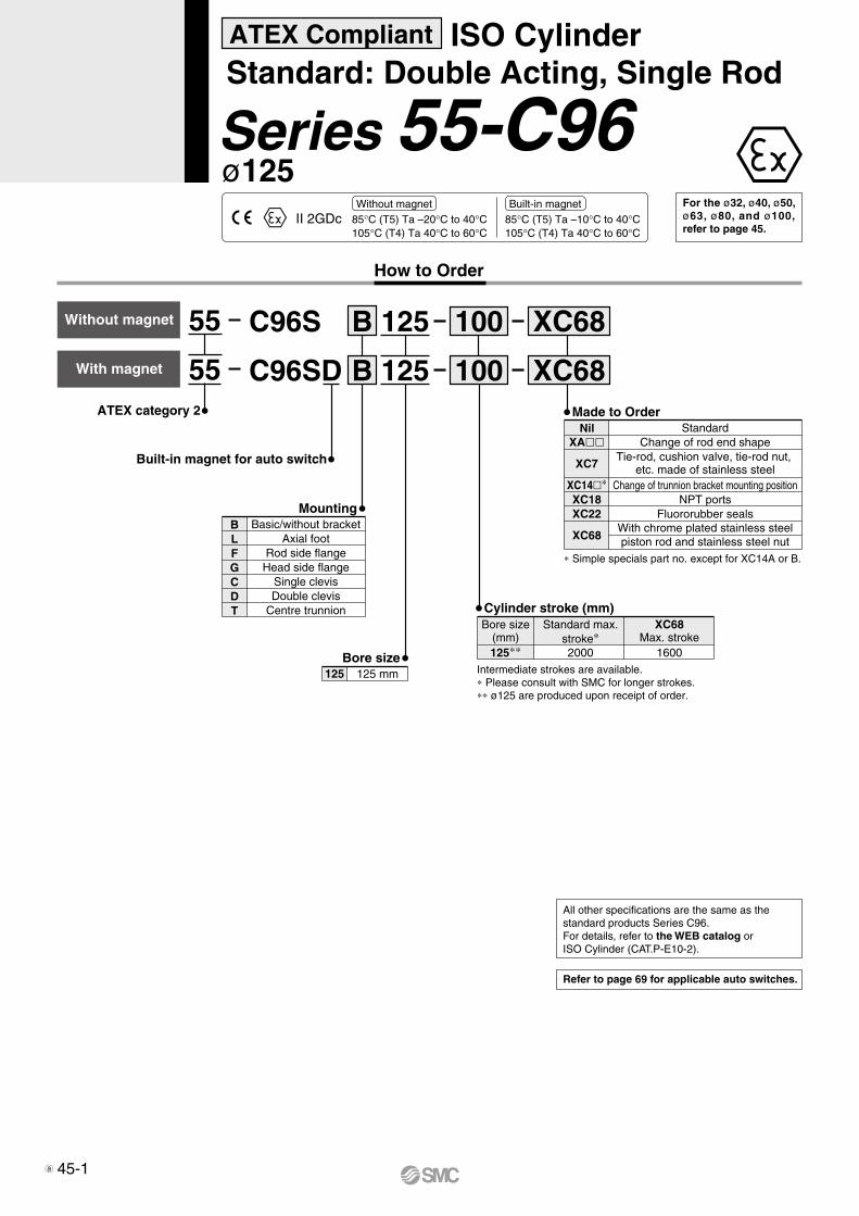
125
125
XC68
XC68
Bore size125 125 mm
Cylinder stroke (mm)
125∗∗
Bore size(mm)
Standard max.stroke∗
XC68Max. stroke
2000 1600
Made to Order
XA
XC7
XC14∗XC18XC22
XC68
Nil StandardChange of rod end shape
Change of trunnion bracket mounting positionNPT ports
Fluororubber seals
Tie-rod, cushion valve, tie-rod nut, etc. made of stainless steel
With chrome plated stainless steelpiston rod and stainless steel nut
∗ Simple specials part no. except for XC14A or B.
Refer to page 69 for applicable auto switches.
All other specifications are the same as the standard products Series C96.For details, refer to the WEB catalog or ISO Cylinder (CAT.P-E10-2).
100
100
II 2GDc 85°C (T5) Ta –20°C to 40°C105°C (T4) Ta 40°C to 60°C
85°C (T5) Ta –10°C to 40°C105°C (T4) Ta 40°C to 60°C
Without magnet Built-in magnet
ATEX Compliant ISO CylinderStandard: Double Acting, Single Rod
Series 55-C96ø125
How to Order
C96S B
C96SD B
Built-in magnet for auto switch
MountingBasic/without bracket
Axial footRod side flangeHead side flange
Single clevisDouble clevis
Centre trunnion
BLFGCDT
With magnet
Without magnet 55
55ATEX category 2
Intermediate strokes are available.∗ Please consult with SMC for longer strokes.∗∗ ø125 are produced upon receipt of order.
For the ø32, ø40, ø50, ø63, ø80, and ø100, refer to page 45.
45-1a

C96S B W32 100
C96SD B W32 100
Built-in magnet for auto switch
Bore size3240506380100
32 mm 40 mm 50 mm 63 mm 80 mm100 mm
RodW Double rod
MountingBasic/without bracket
Axial footRod side flangeCentre trunnion
BLFT
Cylinder stroke (mm)
32
40
50
63
80
100
Bore size(mm)
Standard stroke (mm)
1000
1000
1000
1000
1000
1000
25, 50, 80, 100, 125, 160, 200250, 320, 400, 50025, 50, 80, 100, 125, 160, 200250, 320, 400, 50025, 50, 80, 100, 125, 160, 200250, 320, 400, 500, 60025, 50, 80, 100, 125, 160, 200250, 320, 400, 500, 60025, 50, 80, 100, 125, 160, 200250, 320, 400, 500, 600, 700, 80025, 50, 80, 100, 125, 160, 200250, 320, 400, 500, 600, 700, 800
Intermediate strokes are available.∗ Please consult with SMC for longer strokes.
With magnet
Without magnet 55
55ATEX category 2
XC68
XC68Made to OrderNil
XAXC4
XC7
XC14∗XC22
XC65
XC68
StandardChange of rod end shape
With chrome plated stainless steelpiston rod and stainless steel nut
Made of Stainless Steel(Combination of XC7 and XC68)
II 2GDc 85°C (T5) Ta –20°C to 40°C105°C (T4) Ta 40°C to 60°C
85°C (T5) Ta –10°C to 40°C105°C (T4) Ta 40°C to 60°C
With heavy duty scraper (ø32 to ø100)
Change of trunnion bracket mounting positionFluororubber seals
Tie-rod, cushion valve, tie-rod nut, etc. made of stainless steel
Without magnet Built-in magnet
ATEX Compliant ISO CylinderStandard: Double Acting, Double Rod
Series 55-C96Wø32, ø40, ø50, ø63, ø80, ø100
For the ø125, refer to page 46-1.
How to Order
Refer to page 69 for applicable auto switches.
All other specifications are the same as the standard products Series C96W.For details, refer to the WEB catalog or ISO Cylinder (CAT.P-E10-2).
Max. stroke∗
∗ Simple specials part no. except for XC14A or B.
C
C
46 a

W125
W125
Bore size125 125 mm
Cylinder stroke (mm)
125∗∗Bore size (mm) Max. stroke∗
1000
XC68
XC68
100
100
For the ø32, ø40, ø50, ø63, ø80, and ø100, refer to page 46.
II 2GDc 85°C (T5) Ta –20°C to 40°C105°C (T4) Ta 40°C to 60°C
85°C (T5) Ta –10°C to 40°C105°C (T4) Ta 40°C to 60°C
Without magnet Built-in magnet
ATEX Compliant ISO CylinderStandard: Double Acting, Double Rod
Series 55-C96Wø125
C96S B
C96SD B
Built-in magnet for auto switch
MountingBasic/without bracket
Axial footRod side flangeCentre trunnion
BLFT
With magnet
Without magnet 55
55ATEX category 2
How to Order
RodW Double rod
Intermediate strokes are available.∗ Please consult with SMC for longer strokes.∗∗ ø125 are produced upon receipt of order.
Refer to page 69 for applicable auto switches.
All other specifications are the same as the standard products Series C96W.For details, refer to the WEB catalog or ISO Cylinder (CAT.P-E10-2).
Made to OrderNil
XA
XC7
XC14∗XC18XC22
XC68
StandardChange of rod end shape
With chrome plated stainless steelpiston rod and stainless steel nut
Change of trunnion bracket mounting positionNPT ports
Fluororubber seals
Tie-rod, cushion valve, tie-rod nut, etc. made of stainless steel
∗ Simple specials part no. except for XC14A or B.
46-1a
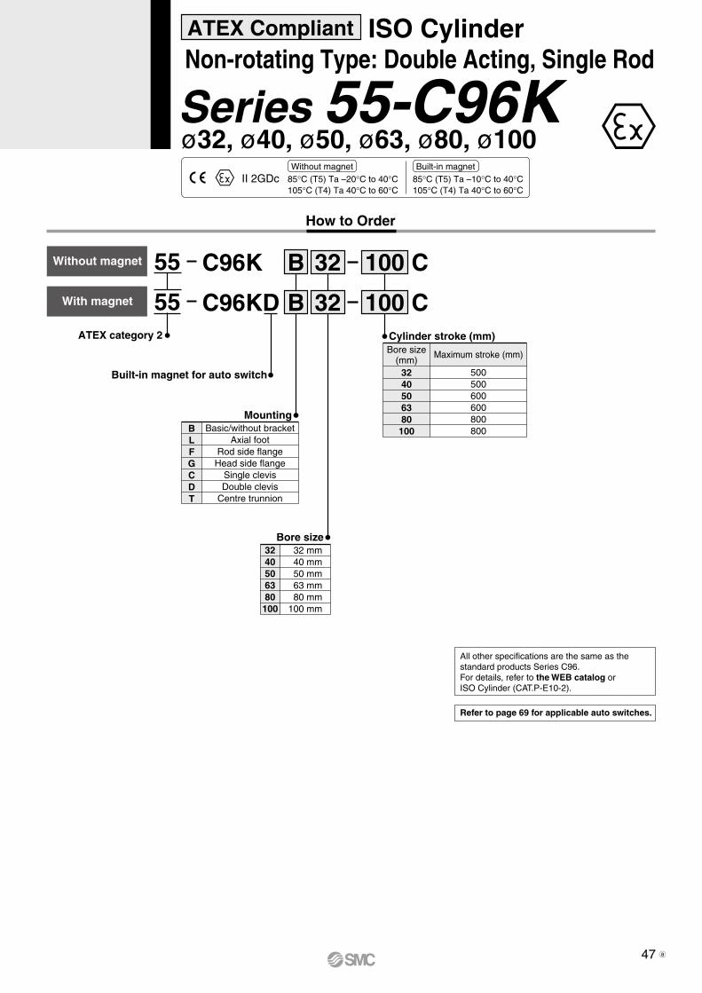
C96K B 32 100
C96KD B 32 100
Built-in magnet for auto switch
Bore size3240506380100
32 mm 40 mm 50 mm 63 mm 80 mm100 mm
MountingBasic/without bracket
Axial footRod side flangeHead side flange
Single clevisDouble clevis
Centre trunnion
BLFGCDT
Cylinder stroke (mm)
With magnet
Without magnet 55
55ATEX category 2
3240506380100
Bore size(mm)
Maximum stroke (mm)
500500600600800800
II 2GDc 85°C (T5) Ta –20°C to 40°C105°C (T4) Ta 40°C to 60°C
85°C (T5) Ta –10°C to 40°C105°C (T4) Ta 40°C to 60°C
ATEX Compliant ISO CylinderNon-rotating Type: Double Acting, Single Rod
Series 55-C96K
How to Order
Without magnet Built-in magnet
Refer to page 69 for applicable auto switches.
All other specifications are the same as the standard products Series C96.For details, refer to the WEB catalog or ISO Cylinder (CAT.P-E10-2).
C
C
47
ø32, ø40, ø50, ø63, ø80, ø100
a

C96K B W32 100
C96KD B W32 100
Built-in magnet for auto switch
Bore size3240506380100
32 mm 40 mm 50 mm 63 mm 80 mm100 mm
W Double rod
MountingBasic/without bracket
Axial footRod side flangeCentre trunnion
BLFT
Cylinder stroke (mm)
With magnet
Without magnet 55
55ATEX category 2
II 2GDc 85°C (T5) Ta –20°C to 40°C105°C (T4) Ta 40°C to 60°C
85°C (T5) Ta –10°C to 40°C105°C (T4) Ta 40°C to 60°C
3240506380100
Rod
Bore size(mm)
Maximum stroke (mm)
500500600600800800
How to Order
ATEX Compliant ISO CylinderNon-rotating Type: Double Acting, Double Rod
Series 55-C96KWWithout magnet Built-in magnet
Refer to page 69 for applicable auto switches.
All other specifications are the same as the standard products Series C96W.For details, refer to the WEB catalog or ISO Cylinder (CAT.P-E10-2).
C
C
48
ø32, ø40, ø50, ø63, ø80, ø100
a

C96Y B 32 100
C96YD B 32 100
Built-in magnet for auto switch
Bore size3240506380100125
32 mm 40 mm 50 mm 63 mm 80 mm100 mm125 mm
MountingBasic/without bracket
Axial footRod side flangeHead side flange
Single clevisDouble clevis
Centre trunnion
BLFGCDT
Cylinder stroke (mm)
With magnet
Without magnet 55
55ATEX category 2
3240506380100125
Bore size(mm)
Maximum stroke (mm)
800 80010001000100010001000
II 2GDc 85°C (T5) Ta –20°C to 40°C105°C (T4) Ta 40°C to 60°C
85°C (T5) Ta –10°C to 40°C105°C (T4) Ta 40°C to 60°C
ATEX Compliant ISO CylinderSmooth cylinder: Double Acting, Single Rod
Series 55-C96YWithout magnet Built-in magnet
How to Order
Refer to page 69 for applicable auto switches.
All other specifications are the same as the standard products Series C96.For details, refer to the WEB catalog or ISO Cylinder (CAT.P-E10-2).
49
ø32, ø40, ø50, ø63, ø80, ø100, ø125

CP96S B 32
Cylinder stroke (mm)
Bore size3240506380100
32 mm 40 mm 50 mm 63 mm 80 mm100 mm
100
CP96SD B 32 100 XC68
XC68
MountingBasic/without bracket
Axial footRod side flangeHead side flange
Single clevisDouble clevis
BLFGCD
Built-in magnet for auto switch
With magnet
Without magnet 55
55ATEX category 2
32
40
50
63
80
100
Bore size(mm)
Standard stroke (mm) Max. stroke∗
2000
2000
2000
2000
2000
2000
Intermediate strokes are available.∗ Please consult with SMC for longer strokes.
25, 50, 80, 100, 125, 160, 200250, 320, 400, 50025, 50, 80, 100, 125, 160, 200250, 320, 400, 50025, 50, 80, 100, 125, 160, 200250, 320, 400, 500, 60025, 50, 80, 100, 125, 160, 200250, 320, 400, 500, 60025, 50, 80, 100, 125, 160, 200250, 320, 400, 500, 600, 700, 80025, 50, 80, 100, 125, 160, 200250, 320, 400, 500, 600, 700, 800
II 2GDc 85°C (T5) Ta –20°C to 40°C105°C (T4) Ta 40°C to 60°C
85°C (T5) Ta –10°C to 40°C105°C (T4) Ta 40°C to 60°C
NilXAXC4
XC7
XC22
XC65
XC68
StandardChange of rod end shape
With heavy duty scraper (ø32 to ø100)
Fluororubber seals
Tie-rod, cushion valve, tie-rod nut, etc. made of stainless steel
With chrome plated stainless steelpiston rod and stainless steel nut
Made of Stainless Steel(Combination of XC7 and XC68)
Made to Order
How to Order
ATEX Compliant ISO CylinderStandard: Double Acting, Single Rod
Series 55-CP96Without magnet Built-in magnet
Refer to page 69 for applicable auto switches.
All other specifications are the same as the standard products Series CP96.For details, refer to the WEB catalog or ISO Cylinder (CAT.P-E10-2).
XC65, XC68Max. stroke
1800
1700
1700
1700
1700
1700
For the ø125, refer to page 50-1.
C
C
50
ø32, ø40, ø50, ø63, ø80, ø100
a

CP96S B
Bore size125 125 mm
CP96SD B
MountingBasic/without bracket
Axial footRod side flangeHead side flange
Single clevisDouble clevis
BLFGCD
Built-in magnet for auto switch
With magnet
Without magnet 55
55ATEX category 2
Intermediate strokes are available.∗ Please consult with SMC for longer strokes.∗∗ ø125 are produced upon receipt of order.
II 2GDc 85°C (T5) Ta –20°C to 40°C105°C (T4) Ta 40°C to 60°C
85°C (T5) Ta –10°C to 40°C105°C (T4) Ta 40°C to 60°C
NilXA
XC7
XC18XC22
XC68
StandardChange of rod end shape
NPT portsFluororubber seals
Tie-rod, cushion valve, tie-rod nut, etc. made of stainless steel
With chrome plated stainless steelpiston rod and stainless steel nut
Made to Order
How to Order
ATEX Compliant ISO CylinderStandard: Double Acting, Single Rod
Series 55-CP96Without magnet Built-in magnet
Refer to page 69 for applicable auto switches.
All other specifications are the same as the standard products Series CP96.For details, refer to the WEB catalog or ISO Cylinder (CAT.P-E10-2).
125
125 XC68
XC68100
100
Cylinder stroke (mm)
125∗∗
Bore size(mm) Max. stroke∗
2000
XC68Max. stroke
1600
For the ø32, ø40, ø50, ø63, ø80, and ø100, refer to page 50.
50-1
ø125
a

CP96S B W32
Cylinder stroke (mm)
Bore size3240506380100
32 mm 40 mm 50 mm 63 mm 80 mm100 mm
100
CP96SD B W32
Rod
100
MountingBasic/without bracket
Axial footRod side flange
BLF
Double rodW
32
40
50
63
80
100
Bore size(mm)
Standard stroke (mm) Max. stroke∗
1000
1000
1000
1000
1000
1000
Intermediate strokes are available.∗ Please consult with SMC for longer strokes
25, 50, 80, 100, 125, 160, 200250, 320, 400, 50025, 50, 80, 100, 125, 160, 200250, 320, 400, 50025, 50, 80, 100, 125, 160, 200250, 320, 400, 500, 60025, 50, 80, 100, 125, 160, 200250, 320, 400, 500, 60025, 50, 80, 100, 125, 160, 200250, 320, 400, 500, 600, 700, 80025, 50, 80, 100, 125, 160, 200250, 320, 400, 500, 600, 700, 800
With magnet
Without magnet 55
55ATEX category 2
Built-in magnet for auto switch
II 2GDc 85°C (T5) Ta –20°C to 40°C105°C (T4) Ta 40°C to 60°C
85°C (T5) Ta –10°C to 40°C105°C (T4) Ta 40°C to 60°C
XC68
XC68
NilXAXC4
XC7
XC22
XC65
XC68
StandardChange of rod end shape
With heavy duty scraper (ø32 to ø100)
Fluororubber seals
Tie-rod, cushion valve, tie-rod nut, etc. made of stainless steel
With chrome plated stainless steelpiston rod and stainless steel nut
Made of Stainless Steel(Combination of XC7 and XC68)
Made to Order
ATEX Compliant ISO CylinderStandard: Double Acting, Double Rod
Series 55-CP96WWithout magnet Built-in magnet
How to Order
Refer to page 69 for applicable auto switches.
All other specifications are the same as the standard products Series CP96W.For details, refer to the WEB catalog or ISO Cylinder (CAT.P-E10-2).
For the ø125, refer to page 51-1.
C
C
51
ø32, ø40, ø50, ø63, ø80, ø100
a

CP96S B
Bore size125 125 mm
CP96SD B
Rod
MountingBasic/without bracket
Axial footRod side flange
BLF
Double rodW
Intermediate strokes are available.∗ Please consult with SMC for longer strokes.∗∗ ø125 are produced upon receipt of order.
With magnet
Without magnet 55
55ATEX category 2
Built-in magnet for auto switch
II 2GDc 85°C (T5) Ta –20°C to 40°C105°C (T4) Ta 40°C to 60°C
85°C (T5) Ta –10°C to 40°C105°C (T4) Ta 40°C to 60°C
NilXA
XC7
XC18XC22
XC68
StandardChange of rod end shape
NPT portsFluororubber seals
Tie-rod, cushion valve, tie-rod nut, etc. made of stainless steel
With chrome plated stainless steelpiston rod and stainless steel nut
Made to Order
ATEX Compliant ISO CylinderStandard: Double Acting, Double Rod
Series 55-CP96WWithout magnet Built-in magnet
How to Order
Refer to page 69 for applicable auto switches.
All other specifications are the same as the standard products Series CP96W.For details, refer to the WEB catalog or ISO Cylinder (CAT.P-E10-2).
For the ø32, ø40, ø50, ø63, ø80, and ø100, refer to page 51.
W125
W125 XC68
XC68100
100
Cylinder stroke (mm)
125∗∗Bore size (mm) Max. stroke∗
1000
51-1
ø125
a
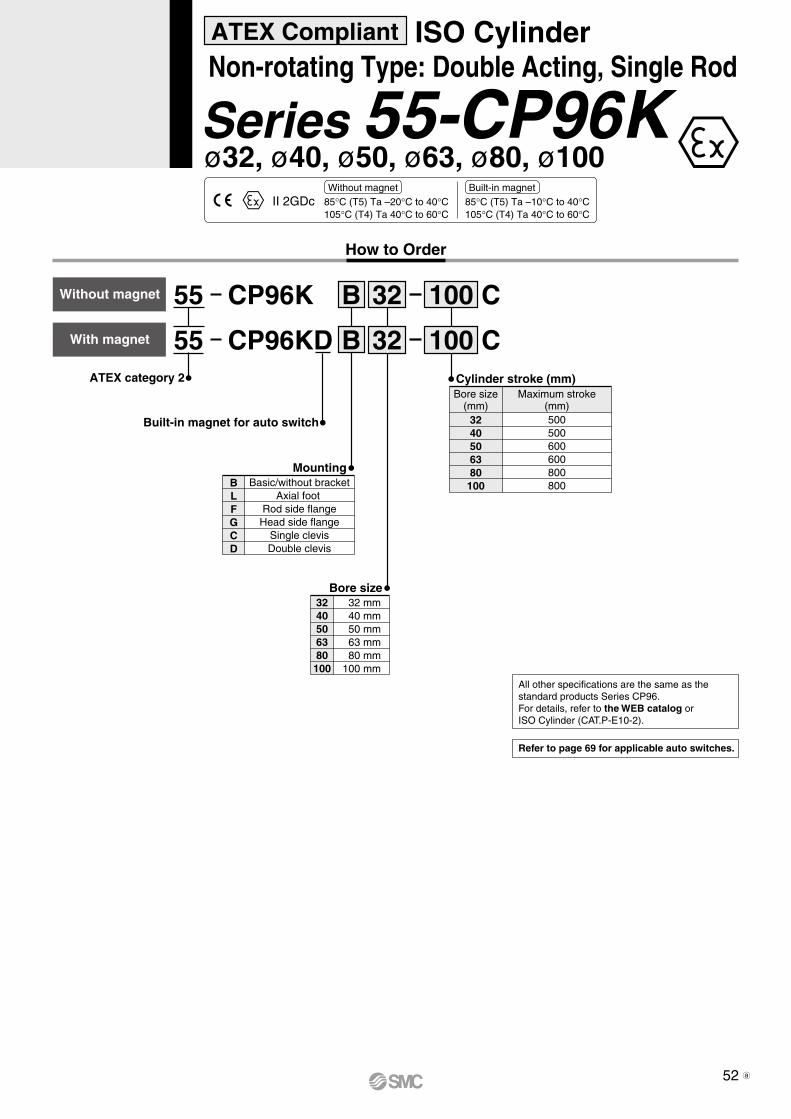
CP96K B 32
Bore size3240506380100
32 mm 40 mm 50 mm 63 mm 80 mm100 mm
100
CP96KD B 32 100
MountingBasic/without bracket
Axial foot Rod side flangeHead side flange
Single clevisDouble clevis
BLFGCD
Built-in magnet for auto switch
With magnet
Without magnet 55
55ATEX category 2
II 2GDc 85°C (T5) Ta –20°C to 40°C105°C (T4) Ta 40°C to 60°C
85°C (T5) Ta –10°C to 40°C105°C (T4) Ta 40°C to 60°C
Cylinder stroke (mm)
3240506380100
Bore size(mm)
Maximum stroke(mm)500500600600800800
ATEX Compliant ISO CylinderNon-rotating Type: Double Acting, Single Rod
Series 55-CP96KWithout magnet Built-in magnet
How to Order
Refer to page 69 for applicable auto switches.
All other specifications are the same as the standard products Series CP96.For details, refer to the WEB catalog or ISO Cylinder (CAT.P-E10-2).
C
C
52
ø32, ø40, ø50, ø63, ø80, ø100
a

CP96K B 32
Bore size3240506380100
32 mm 40 mm 50 mm 63 mm 80 mm100 mm
100
CP96KD B 32 100
MountingBasic/without bracket
Axial footRod side flange
BLF
With magnet
Without magnet 55
55ATEX category 2
Built-in magnet for auto switch
II 2GDc 85°C (T5) Ta –20°C to 40°C105°C (T4) Ta 40°C to 60°C
85°C (T5) Ta –10°C to 40°C105°C (T4) Ta 40°C to 60°C
Cylinder stroke (mm)
3240506380100
Bore size(mm)
Maximum stroke(mm)500500600600800800
W
W
RodDouble rodW
ATEX Compliant ISO CylinderNon-rotating Type: Double Acting, Double Rod
Series 55-CP96KWWithout magnet Built-in magnet
How to Order
Refer to page 69 for applicable auto switches.
All other specifications are the same as the standard products Series CP96W.For details, refer to the WEB catalog or ISO Cylinder (CAT.P-E10-2).
C
C
53
ø32, ø40, ø50, ø63, ø80, ø100
a

How to Order
C55
With magnet
Without magnet B
B
20
20
10
10
Bore size 20 25 32 40 50 63 80100
20 mm 25 mm 32 mm 40 mm 50 mm 63 mm 80 mm100 mm
Cylinder stroke (mm)
Body optionStandard (Rod end female thread)
Rod end male threadNilM
CD55
Built-in magnet for auto switch
55
55ATEX category 2
MountingBLFGC
Through-hole/Both ends tapped common (Standard)Foot
Rod side flangeHead side flange
Single clevis
Bore size (mm) Standard stroke (mm)
5, 10, 15, 20, 25, 30, 35, 40, 45, 50, 60, 80100, 125, 150
10, 15, 20, 25, 30, 35, 40, 45, 50, 60, 80100, 125
20 to 63
80, 100
Refer to page 69 for applicable auto switches.
ø20, ø25, ø32, ø40, ø50, ø63, ø80, ø100Series 55-C55 ATEX Compliant ISO StandardsCompact Cylinder/Standard type: Double acting, Single rod
85°C(T6) Ta -10°C to 40°C105°C(T4) Ta 40°C to 60°CII 2GDc
All other specifications are the same as the standard products Series C55. For details, refer to the WEB catalog or ISO Cylinder (CAT.P-E10-2).
54

55 CDG1
L 25
L
N
N 25
55 CG1 100
100
XC85
XC85
Bore size20253240
20 mm25 mm32 mm40 mm
50 63 80100
50 mm 63 mm 80 mm100 mm
With magnet
Without magnet
Cylinder stroke (mm)
TypeNA
Rubber cushionAir cushion
Built-in magnet for auto switch
MountingBLFGU∗T∗D
BasicAxial foot
Rod side flangeHead side flangeRod side trunnionHead side trunnion
Clevis∗ Not available for ø80 or ø100.Note) Mounting brackets are shipped
together, (but not assembled).
Note 1) “How to Order” for XC10, and XC11 are different from the above. Refer to “How to Order” in Best Pneumatics No. 2.
Note 2) Not available for rubber cushion type.
Note 3) XC10 and XC11 are not applicable to XC85.
Port thread type
NilTN
TF
RcNPT
M5 x 0.8G
ø20 to ø100ø20 to ø100
ø20, ø25ø32 to ø100
Rubber cushion
Made to OrderNil
XC85XC10 Note 1)
XC11 Note 1) 2)
StandardFood grade grease
Dual stroke cylinder/Double rodDual stroke cylinders/Single rod
Nil
TN
TF
M5 x 0.8Rc
M5 x 0.8NPT
M5 x 0.8G
ø20, ø25ø32 to ø100
ø20, ø25ø32 to ø100
ø20, ø25ø32 to ø100
Air cushion
ATEX category 2
Refer to page 69 for applicable auto switches.
Bore size (mm)
20
25
32
40
50, 63
80
100
Standard stroke Note 1) (mm)
25, 50, 75, 100, 125, 150, 200
25, 50, 75, 100, 125, 150, 200, 250, 300
Long stroke Note 2)
(mm)
201 to 350
301 to 400
301 to 450
301 to 800
301 to 1200
301 to 1400
301 to 1500
Note 1) Manufacture of intermediate strokes at 1 mm intervals is possible. (Spacers are not used.)
Note 2) Long stroke is compatible with the axial foot and rod side flange types. When other mounting brackets are used or the long stroke exceeds the limit, the allowable maximum stroke length is determined using the stroke selection table (Best Pneumatics No. 2).
How to Order
ø20, ø25, ø32, ø40, ø50, ø63, ø80, ø100Series 55-CG1 ATEX Compliant Air Cylinder/Standard type: Double acting, Single rod
II 2GDc95°C (T5) Ta –10°C to 40°C115°C (T4) Ta 40°C to 60°C
All other specifications are the same as the standard products Series CG1. For details, refer to the WEB catalog or Best Pneumatics No. 2.
55

CDG1W55
L 25
L
N
N 25
W55 CG1 100
100
Cylinder stroke (mm)
MountingBLF
U∗
BasicAxial footFlange
Centre trunnion∗ Not available for bore size ø80
and ø100.Note) Mounting brackets are shipped
together, (but not assembled).
Double Acting/Double Rod
Built-in magnet for auto switch
TypeNA
Rubber cushionAir cushion
Bore size20253240
20 mm25 mm32 mm40 mm
50 63 80100
50 mm 63 mm 80 mm100 mm
With magnet
Without magnet
ATEX category 2
Bore size (mm)
20
25
32
40
50, 63
80
100
Standard stroke Note 1) (mm)
25, 50, 75, 100, 125, 150, 200
25, 50, 75, 100, 125, 150, 200250, 300
Long stroke (mm)
201 to 350
301 to 400
301 to 450
301 to 800
301 to 1200
301 to 1400
301 to 1500
Note 1) Manufacture of intermediate strokes at 1 mm intervals is possible. (Spacers are not used.)
Note 2) Long stroke is compatible with the axial foot and rod side flange types. When other mounting brackets are used or the long stroke exceeds the limit, the allowable maximum stroke length is determined using the stroke selection table (Best Pneumatics No. 2).
XC85
XC85
Made to OrderNil
XC85Standard
Food grade grease
How to Order
ø20, ø25, ø32, ø40, ø50, ø63, ø80, ø100Series 55-CG1W ATEX Compliant Air Cylinder/Standard type: Double acting, Double rod
II 2GDc95°C (T5) Ta –10°C to 40°C115°C (T4) Ta 40°C to 60°C
Refer to page 69 for applicable auto switches.
All other specifications are the same as the standard products Series CG1W. For details, refer to the WEB catalog or Best Pneumatics No. 2.
Port thread type
NilTN
TF
RcNPT
M5 x 0.8G
ø20 to ø100ø20 to ø100
ø20, ø25ø32 to ø100
Rubber cushion
Nil
TN
TF
M5 x 0.8Rc
M5 x 0.8NPT
M5 x 0.8G
ø20, ø25ø32 to ø100
ø20, ø25ø32 to ø100
ø20, ø25ø32 to ø100
Air cushion
56

Bore size
125140160180200250300
125 mm140 mm160 mm180 mm200 mm250 mm300 mm
MountingBLFGCDT
BasicFoot
Rod side flangeHead side flange
Single clevisDouble clevis
Centre trunnion
Cylinder stroke (mm)
TypeN
Without cushionWith cushion in rod side
With cushion in head sideWith cushion in both sides
Cushion
Cus
hion
NRH
Nil
Tubing material
Non-lube type
Non-lube type
Symbol
125, 140160
125, 140160
180 to 300125, 140
160
Tubing material Stroke range(mm)
Aluminum
Steel
Steel
1000 or less1200 or less1001 or more1201 or more
All strokes1000 or less1200 or less
Nil
F
Bore size(mm)
CS155 L 300160NATEX category 2
Tubing material Aluminum Steel
Mountingbracket
Boresize
125
140
160
180
200
250
300
Basic, Head side flange,Single clevis, Double clevis,
Centre trunnion, Foot,Rod side flange
1000 or less
1000 or less
1200 or less
—
—
—
—
1000 or less
1200 or less
1200 or less
1200 or less
1200 or less
1200 or less
1200 or less
1600 or less
1600 or less
1600 or less
2000 or less
2000 or less
2400 or less
2400 or less
Basic,Head side flange,
Single clevis,Double clevis,
Centre trunnion
FootRod side flange
How to Order
Non-lube type: ø125, ø140, ø160, ø180, ø200, ø250, ø300Series 55-CS1 ATEX Compliant Air Cylinder/Standard type: Non-lube
95°C (T5) Ta 0°C to 40°C115°C (T4) Ta 40°C to 60°CII 2GDc
∗ If specifying more than one symbol, indicate them alphabetically.
Refer to page 69 for applicable auto switches.
All other specifications are the same as the standard products Series CS1. For details, refer to the WEB catalog or Best Pneumatics No. 2.
Class 2 Pressure Vessel
Bore size(mm)
Cylinder stroke(mm)
200
250
300
998
813
564
The cylinder with a stroke exceeding the level shown below that is applicable to the Class 2 Pressure Vessel Act cannot be installed or used in Japan.
57

CDS155 300
Built-in magnet for auto switch
Mounting
160
Bore size
Type
Non-lube type
L
BasicFoot
Rod side flangeHead side flange
Single clevisDouble clevis
Centre trunnion
BLFGCDT
Non-lube typeN
125140160180200
125 mm140 mm160 mm180 mm200 mm
With magnet
ATEX category 2
CushionNRHNil
Without cushionWith cushion in rod side
With cushion in head sideWith cushion in both sides
Cushion
∗ If specifying more than one symbol, indicate them alphabeti-cally.
Bore size(mm)
125, 140
160
180
200
Basic, Head side flange, Single clevis,Double clevis, Centre trunnion
1000 or less
1200 or less
1200 or less
1200 or less
Foot,Rod side flange
1400 or less
1400 or less
1500 or less
1200 or less
Maximum Stroke
Cylinder stroke (mm)
N
How to Order
ø125, ø140, ø160, ø180, ø200Series 55-CDS1 ATEX Compliant Air cylinder
95°C (T5) Ta 0°C to 40°C115°C (T4) Ta 40°C to 60°CII 2GDc
Refer to page 69 for applicable auto switches.
All other specifications are the same as the standard products Series CS1. For details, refer to the WEB catalog or Best Pneumatics No. 2.
Class 2 Pressure Vessel
Bore size(mm)
Cylinder stroke(mm)
200 998
The cylinder with a stroke exceeding the level shown below that is applicable to the Class 2 Pressure Vessel Act cannot be installed or used in Japan.
58

Symbol
125, 140160180200
250, 300125, 140
160
Tubing material
Aluminum
Steel
Steel
Nil
F
Bore size(mm)
Tubing material
WCS1
CDS1W55With magnet
Without magnet L
L
100
100
Built-in magnet for auto switch
125
125
Mounting
Double rod
Type
Cylinder stroke (mm)
BasicFoot
Rod side flangeCentre trunnion
BLFT
Non-lube typeN
∗ It is not available with auto switch.
Non-lube type125140160180200250∗300∗
125 mm140 mm160 mm180 mm200 mm250 mm300 mm
Bore size
CushionNRHNil
Without cushionWith cushion in rod sideWith cushion in head sideWith cushion in both sides
Cushion
∗ If specifying more than one symbol, indicate them alphabetically.
Tubing material
MountingbracketBore
size (mm)
125, 140
160
180
200
250, 300
Aluminum
Basic, Foot, Rod side flange, Centre trunnion
1000 or less
1200 or less
—
—
—
1000 or less
1200 or less
1200 or less
1200 or less
—
Steel
Without magnet With magnet Without magnet
1000 or less
1200 or less
1200 or less
1200 or less
1200 or less
55
ATEX category 2
N
N
95°C (T5) Ta 0°C to 40°C115°C (T4) Ta 40°C to 60°CII 2GDc
How to Order
Non-lube type: ø125, ø140, ø160, ø180, ø200, ø250, ø300Series 55-CS1W ATEX Compliant
Air Cylinder: Double Rod Type
Refer to page 69 for applicable auto switches.
All other specifications are the same as the standard products Series CS1W. For details, refer to the WEB catalog or Best Pneumatics No. 2.
Class 2 Pressure Vessel
Bore size(mm)
Cylinder stroke(mm)
200
250
300
998
813
564
The cylinder with a stroke exceeding the level shown below that is applicable to the Class 2 Pressure Vessel Act cannot be installed or used in Japan.
59
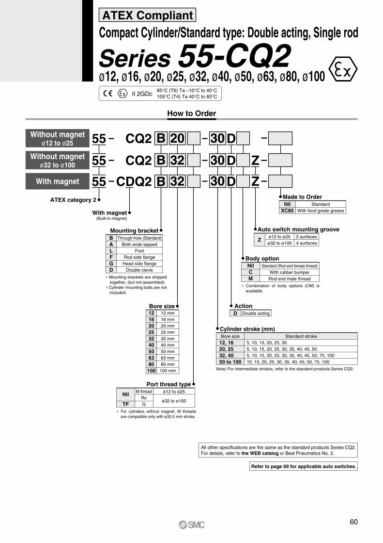
How to Order
30
30
32
32
With magnet(Built-in magnet)
CQ2 B
BCDQ2
Cylinder stroke (mm)
DWith magnet
Body optionNilCM
Standard (Rod end female thread)With rubber bumperRod end male thread
ActionD Double acting
D
Bore size121620253240506380100
12 mm16 mm20 mm25 mm32 mm40 mm50 mm63 mm80 mm100 mm
∗ For cylinders without magnet, M threads are compatible only with ø32-5 mm stroke.
M threadRcG
ø12 to ø25
ø32 to ø100
Port thread type
Nil
TF
Through-hole (Standard)Both ends tapped
FootRod side flangeHead side flange
Double clevis
BALFGD
Mounting bracket
Without magnetø12 to ø25
Without magnetø32 to ø100
3020CQ2 B D
Z
Z
Auto switch mounting groove
Zø12 to ø25
ø32 to ø1002 surfaces4 surfaces
Made to OrderNil
XC85Standard
With food grade grease
∗ Combination of body options (CM) is available.
Note) For intermediate strokes, refer to the standard products Series CQ2.
Bore size
12, 1620, 2532, 4050 to 100
Standard stroke5, 10, 15, 20, 25, 305, 10, 15, 20, 25, 30, 35, 40, 45, 505, 10, 15, 20, 25, 30, 35, 40, 45, 50, 75, 10010, 15, 20, 25, 30, 35, 40, 45, 50, 75, 100
55
55
55ATEX category 2
∗ Mounting brackets are shipped together, (but not assembled).
∗ Cylinder mounting bolts are not included.
ø12, ø16, ø20, ø25, ø32, ø40, ø50, ø63, ø80, ø100Series 55-CQ2 ATEX Compliant
Compact Cylinder/Standard type: Double acting, Single rod
85°C (T6) Ta –10°C to 40°C105°C (T4) Ta 40°C to 60°CII 2GDc
Refer to page 69 for applicable auto switches.
All other specifications are the same as the standard products Series CQ2. For details, refer to the WEB catalog or Best Pneumatics No. 2.
60
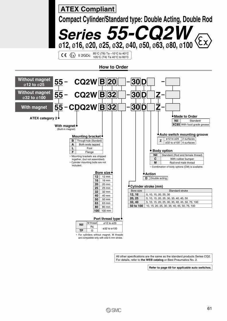
How to Order
30
30
32
32
With magnet(Built-in magnet)
B
B
Cylinder stroke (mm)
DWith magnet
ActionD Double acting
D
Bore size121620253240506380100
12 mm16 mm20 mm25 mm32 mm40 mm50 mm63 mm80 mm
100 mm
∗ For cylinders without magnet, M threads are compatible only with ø32-5 mm stroke.
M threadRcG
ø12 to ø25
ø32 to ø100
Port thread type
Nil
TF
Without magnetø12 to ø25
Without magnetø32 to ø100
3020B D
Z
Z
Auto switch mounting groove
Zø12 to ø25
ø32 to ø1002 surfaces4 surfaces
Bore size
12, 1620, 2532, 4050 to 100
Standard stroke5, 10, 15, 20, 25, 305, 10, 15, 20, 25, 30, 35, 40, 45, 505, 10, 15, 20, 25, 30, 35, 40, 45, 50, 75, 10010, 15, 20, 25, 30, 35, 40, 45, 50, 75, 100
55
55
55ATEX category 2
CQ2W
CDQ2W
CQ2W
Body optionNilCM
Standard (Rod end female thread)With rubber bumperRod end male thread
∗ Combination of body options (CM) is available.
Through-hole (Standard)Both ends tapped
FootFlange
BALF
Mounting bracket
∗ Mounting brackets are shipped together, (but not assembled).
∗ Cylinder mounting bolts are not included.
ø12, ø16, ø20, ø25, ø32, ø40, ø50, ø63, ø80, ø100Series 55-CQ2W ATEX Compliant
Compact Cylinder/Standard type: Double Acting, Double Rod
85°C (T6) Ta –10°C to 40°C105°C (T4) Ta 40°C to 60°CII 2GDc
Refer to page 69 for applicable auto switches.
All other specifications are the same as the standard products Series CQ2. For details, refer to the WEB catalog or Best Pneumatics No. 2.
Made to OrderNil
XC85Standard
With food grade grease
61

Built-in magnet for auto switch
CQ2
With magnet
Without magnet
CDQ2
Body optionNilM
Standard (Rod end female thread)Rod end male thread
Bore size
Mounting bracketALFGD
Both ends tappedFoot
Rod side flangeHead side flange
Double clevis
200
200
32
32
DC
DC
A
A
ActionD Double acting
CushionC Rubber cushion
55
55ATEX category 2
Bore size Standard stroke
125, 150, 175, 200, 250, 30032, 40, 5063, 80, 100
Cylinder stroke (mm)
32 mm40 mm50 mm63 mm80 mm
100 mm
3240506380
100
RcG
Port thread typeNilTF
Z
Auto switch mounting grooveZ 4 surfaces
Z
How to Order
ø32, ø40, ø50, ø63, ø80, ø100Series 55-CQ2 ATEX Compliant
Compact Cylinder: Long Stroke/Double Acting, Single Rod
85°C (T6) Ta –10°C to 40°C105°C (T4) Ta 40°C to 60°CII 2GDc
Refer to page 69 for applicable auto switches.
All other specifications are the same as the standard products Series CQ2. For details, refer to the WEB catalog or Best Pneumatics No. 2.
∗ Mounting brackets are shipped together, (but not assembled).
Made to OrderNil
XC85Standard
With food grade grease
62

Built-in magnet for auto switch
CQ2B
With magnet
Without magnet
CDQ2B
Body option
Cylinder stroke (mm)
NilM
Standard (Rod end female thread)Rod end male thread
Bore size125140160180200
125 mm140 mm160 mm180 mm200 mm
BMounting bracket
Standard (Through-hole/Both ends tapped common)
125
125 30
30
DC
DC
ActionD Double acting
CushionC Rubber cushion
∗ Cylinder mounting bolts are not included.
55
55ATEX category 2
Refer to page 69 for applicable auto switches.
Bore size
125, 140, 160180, 200
10, 20, 30, 40, 50, 75, 100125, 150, 175, 200, 250, 300
Standard stroke
Z
Auto switch mounting grooveZ 4 surfaces
Z
RcG
NilTF
Port thread type
How to Order
ø125, ø140, ø160, ø180, ø200Series 55-CQ2 ATEX Compliant Compact Cylinder: Large Bore Size/Double Acting, Single Rod
85°C (T6) Ta –10°C to 40°C105°C (T4) Ta 40°C to 60°CII 2GDc
All other specifications are the same as the standard products Series CQ2. For details, refer to the WEB catalog or Best Pneumatics No. 2.
Made to OrderNil
XC85Standard
With food grade grease
63

How to Order
CXS55 M 10020
BearingSlide bearing
Ball bushing bearingML
Bore size/Standard stroke (mm)Bore size
6 10, 20, 30, 40, 50
10, 15, 20, 25, 30, 35, 40, 45, 50, 60, 70, 75
10, 15, 20, 25, 30, 35, 40, 45, 50, 60, 70, 75, 80, 90, 100
15, 2025, 32
Standard stroke (mm)
10
ATEX category 2
Port thread typeBore sizeø6 to ø20
ø25, ø32
TypeM thread
Rc1/8G1/8
Symbol
Nil
TF
65°C (T6) Ta –10°C to 40°C85°C (T6) Ta 40°C to 60°C
ø6, ø10, ø15, ø20, ø25, ø32Series 55-CXS ATEX Compliant Dual Rod Cylinder/Basic Type
II 2GDc
Refer to page 69 for applicable auto switches.
All other specifications are the same as the standard products Series CXS. For details, refer to the WEB catalog or Best Pneumatics No. 3.
Made to OrderNil
XB11Standard
Long stroke type
64

How to Order
L 10020
BearingSlide bearing
Ball bushing bearing
CXS55 W
Double rod type
ATEX category 2
ML
Bore size/Stroke (mm)Bore size
10, 20, 30, 40, 5010, 20, 30, 40, 5010, 20, 30, 40, 50, 75, 100
610, 15
20, 25, 32
Standard stroke
Port thread typeBore sizeø6 to ø20
ø25, ø32
TypeM thread
Rc1/8G1/8
Symbol
Nil
TF
65°C (T6) Ta –10°C to 40°C85°C (T6) Ta 40°C to 60°C
ø6, ø10, ø15, ø20, ø25, ø32Series 55-CXSW ATEX Compliant Dual Rod Cylinder/Double Rod Type
II 2GDc
Refer to page 69 for applicable auto switches.
All other specifications are the same as the standard products Series CXS. For details, refer to the WEB catalog or Best Pneumatics No. 3.
Made to OrderNil
XB11Standard
Long stroke type
65

MY1B55ø25, ø32, ø40
Piping
10 mm16 mm20 mm25 mm32 mm40 mm50 mm63 mm80 mm
100 mm
Bore size101620253240506380
100
BasicATEX category 2
25 300
StandardCentralized piping type
NilG
Port thread typeType
M threadRc
NPTG
ø10, ø16, ø20
ø25 ,ø32, ø40,ø50, ø63, ø80,ø100
Bore sizeSymbol
Nil
TNTF
Note) For ø10, only G is available.
Made to Order
∗ Strokes are manufacturable in 1 mm increments, up to the maximum stroke. However, when exceeding a 2000 mm stroke, specify “-XB11” at the end of the model number.With strokes of 49 mm or less, the air cushion capacity may decrease and it may not be possible to mount multiple auto switches.
Cylinder stroke (mm)
Bore size (mm)
10, 1620, 25, 32, 4050, 63, 80, 100
Standard stroke∗ (mm)
100, 200, 300, 400, 500, 600700, 800, 900, 1000, 12001400, 1600, 1800, 2000
3000
5000
Maximumstroke (mm)
Standard typeLong stroke type
NilXB11
How to Order
ø10, ø16, ø20, ø25, ø32, ø40, ø50, ø63, ø80, ø100Series 55-MY1B ATEX Compliant Mechanically Jointed Rodless Cylinder/Basic Type
75°C (T6) Ta 5°C to 40°C95°C (T5) Ta 40°C to 60°CII 2Gc
Refer to page 69 for applicable auto switches.
All other specifications are the same as the standard products Series MY1B. For details, refer to the WEB catalog or Best Pneumatics.
MY1B 20 300ø10, ø16, ø20ø50, ø63, ø80, ø100 55
Z
66 A

MY1B55Basic
Piping
10 mm16 mm20 mm25 mm32 mm40 mm50 mm63 mm80 mm
100 mm
Bore size101620253240506380
100
BasicATEX category 2
20 300
StandardCentralized piping type
NilG
Port thread typeType
M threadRc
NPTG
ø10, ø16, ø20
ø25 ,ø32, ø40,ø50, ø63, ø80,ø100
Bore sizeSymbol
Nil
TNTF
Note) For ø10, only G is available.
Made to Order
∗ Strokes are manufacturable in 1 mm increments, up to the maximum stroke. However, when exceeding a 2000 mm stroke, specify “-XB11” at the end of the model number.With strokes of 49 mm or less, the air cushion capacity may decrease and it may not be possible to mount multiple auto switches.
Cylinder stroke (mm)
Bore size (mm)
10, 1620, 25, 32, 4050, 63, 80, 100
Standard stroke∗ (mm)
100, 200, 300, 400, 500, 600700, 800, 900, 1000, 12001400, 1600, 1800, 2000
3000
5000
Maximumstroke (mm)
Standard typeLong stroke type
NilXB11
How to Order
ø10, ø16, ø20, ø25, ø32, ø40, ø50, ø63, ø80, ø100Series 55-MY1B ATEX Compliant Mechanically Jointed Rodless Cylinder/Basic Type
75°C (T6) Ta 5°C to 40°C95°C (T5) Ta 40°C to 60°CII 2Gc
Refer to page 69 for applicable auto switches.
All other specifications are the same as the standard products Series MY1B. For details, refer to the WEB catalog or Best Pneumatics No. 2.
55-MY1B series has been remodeled.Click here for details.
66-1 A

MY1M55Slide bearing guide type
Cylinder stroke (mm)
Piping
16 mm20 mm25 mm32 mm40 mm50 mm63 mm
Bore size16202532405063
Slide bearing guide type
ATEX category 2
20 300
StandardCentralized piping type
NilG
G
Port thread typeType
M threadRc
NPTG
ø16, ø20ø25, ø32,ø40, ø50,ø63
Bore sizeSymbol
Nil
TNTF
Made to Order
Bore size(mm)
16
20, 25, 3240, 50, 63
Standard stroke∗ (mm)
100, 200, 300, 400, 500, 600, 700800, 900, 1000, 1200, 1400, 16001800, 2000
3000
5000
Maximumstroke (mm)
∗ Strokes are manufacturable in 1 mm increments, up to the maximum stroke. However,when exceeding a 2000 mm stroke, specify “-XB11” at the end of the model number.With strokes of 49 mm or less, the air cushion capacity may decrease and it may not be possible to mount multiple auto switches.
Standard typeLong stroke type
NilXB11
How to Order
ø16, ø20, ø25, ø32, ø40, ø50, ø63Series 55-MY1M ATEX Compliant Mechanically Jointed Rodless Cylinder/Slide Bearing Guide Type
75°C (T6) Ta 5°C to 40°C95°C (T5) Ta 40°C to 60°CII 2Gc
Refer to page 69 for applicable auto switches.
All other specifications are the same as the standard products Series MY1M. For details, refer to the WEB catalog or Best Pneumatics No. 2.
67

MY1H55ø25, ø32, ø40
Cylinder stroke (mm)
Piping
Bore size10 mm16 mm20 mm25 mm32 mm40 mm
101620253240
Linear guide type
ATEX category 2
25 300
StandardCentralized piping type
NilG
Note) For ø10, only G is available.
Port thread typeType
M threadRc
NPTG
ø10, ø16, ø20
ø25, ø32, ø40
Bore sizeSymbol
Nil
TNTF
Made to Order
Bore size(mm)
10, 16, 20
25, 32, 40
Standard stroke∗ (mm)
50, 100, 150, 200, 250, 300350, 400, 450, 500, 550, 600
1000
1500
Maximumstroke (mm)
∗ Strokes are manufacturable from 50 mm in 1 mm increments, up to the maximum stroke. However, add “-XB10” to the end of the part number for nonstandard strokes from 51 to 599. Also when exceeding a 600 mm stroke, specify “-XB11” at the end of the model number. (Only 10 mm increments are available for size ø10.)
Standard type
Intermediate stroke(using exclusive body)
Long stroke type
Nil
XB10
XB11
How to Order
ø10, ø16, ø20, ø25, ø32, ø40Series 55-MY1H ATEX Compliant Mechanically Jointed Rodless Cylinder/Linear Guide Type
75°C (T6) Ta 5°C to 40°C95°C (T5) Ta 40°C to 60°CII 2Gc
Refer to page 69 for applicable auto switches.
All other specifications are the same as the standard products Series MY1H. For details, refer to the WEB catalog or Best Pneumatics.
MY1H55ø10, ø16, ø20 16 300
Z
68 A

MY1H55Linear guide type
Linear guide type
Cylinder stroke (mm)
Piping
Bore size10 mm16 mm20 mm25 mm32 mm40 mm
101620253240
Linear guide type
ATEX category 2
25 300
StandardCentralized piping type
NilG
Note) For ø10, only G is available.
Port thread typeType
M threadRc
NPTG
ø10, ø16, ø20
ø25, ø32, ø40
Bore sizeSymbol
Nil
TNTF
Made to Order
Bore size(mm)
10, 16, 20
25, 32, 40
Standard stroke∗ (mm)
50, 100, 150, 200, 250, 300350, 400, 450, 500, 550, 600
1000
1500
Maximumstroke (mm)
Cylinder stroke (mm)
∗ Strokes are manufacturable from 50 mm in 1 mm increments, up to the maximum stroke. However, add “-XB10” to the end of the part number for nonstandard strokes from 51 to 599. Also when exceeding a 600 mm stroke, specify “-XB11” at the end of the model number. (Except ø10)
Standard typeIntermediate stroke (using exclusive body)
Long stroke type
NilXB10XB11
253240
25 mm32 mm40 mm
MY1H 55 25
Bore size
300 X1985ATEX category 2
Linear guide type
Port thread typeTypeRc
NPTG
ø25 to ø40
Bore sizeSymbolNilTNTF
PipingStandard
Centralized piping typeNilG
Rust proof guide
253240
50, 100, 150, 200, 250, 300, 350,400, 450, 500, 550, 600, 750
Bore size(mm) Standard stroke∗ (mm)
How to Order
ø10, ø16, ø20, ø25, ø32, ø40Series 55-MY1H ATEX Compliant Mechanically Jointed Rodless Cylinder/Linear Guide Type
75°C (T6) Ta 5°C to 40°C95°C (T5) Ta 40°C to 60°CII 2Gc
Refer to page 69 for applicable auto switches.
All other specifications are the same as the standard products Series MY1H. For details, refer to the WEB catalog or Best Pneumatics No. 2.
∗ X1985 type can only be manufactured with the strokes listed in table.
55-MY1H series has been remodeled.Click here for details.
68-1 A

Model
Switch type
D-M9-588
D-M9V-588
D-M9W-588
D-M9WV-588
D-H7A2-588
D-F7P-588
D-F7PV-588
D-F5P-588
D-Y7P-588
D-Y7PV-588
D-S7P-588
D-S9P-588
D-S9PV-588
D-F6P-588
(16 to 25)
(160 to 250)
(160 to 200)
(160 to 200)
(160 to 250)
(160 to 200)
(125 to 200)
(125 to 200)
(125 to 200)
(125 to 200)
(125 to 200)
(125 to 200)
(125 to 200)
(125 to 200)
(125 to 200)
(125 to 200)
(125 to 200)
(125 to 200)
(Except 50)
(Except 50)
(Except 50)
(Except 50)
(25 to 100)
(25 to 100)
(10 to 20)
(10 to 20)
(25 to 100)
(20 to 63)
(20 to 63)
(20 to 63)
(20 to 63)
(20 to 63)
(25 to 63)
(25 to 63)
(16, 20)
(16, 20)
(25 to 63)
(25 to 40)
(25 to 40)
(25 to 40)
(50 to 100)
(50 to 100)
(20 to 40)
(10, 15)
(10, 15)
(10, 15)
(20 to 40)
(20 to 40)
(10, 15)
(10, 15)
(10, 15)
(20 to 40)
Auto Switch Applicable Cylinder List55-C76
55-C85
55-C95
55-CG1
55-CS1
55-CXS/W
55-C55
55-MY1B
55-MY1M
55-MY1H
55-CRQ2
56-CRB1
56-CRB2
56-CRBU2
D-C73-588D-C80-588
D-A73-588D-A80-588
D-A73H-588D-A80H-588
D-A54-588D-A67-588
D-A90-588D-A93-588
D-A90V-588D-A93V-588
D-90A-588D-93A-588
D-Z73-588D-Z80-588
D-E73A-588D-E80A-588
D-R73-588D-R80-588
(12 to 160)
(12 to 160)
(12 to 160)
(12 to 160)
55-C96
55-CP96
55-CQ2(Z)
∗ ( ): Cylinder sizeNote 1) 55-C85 Band mounting all sizes, and Rail mounting for 8 to 16 only.Note 2) 55-C85 Band mounting only.Note 3) 55-C85 Rail mounting only.Note 4) 55-C85 Rail mounting only.Note 5) 55-C85 Rail mounting only, for 16 to 25 only.
ATEX Compliant
Note 1)
Note 1)
Note 3)
Note 4)
Note 4)
Note 3)
Note 4)
Note 4)
Note 2)
Note 2)
Note 5)
69

Auto Switch Specifications
Grommet
PLC: Programmable Logic Controller
Auto switch part no.Electrical entry directionWiring typeOutput typeApplicable loadPower supplyCurrent consumptionLoad voltageLoad currentInternal voltage dropLeakage currentIndicator lightStandard
D-M9NVD-M9N D-M9B D-M9BV
2-wire—
24 VDC relay, PLC——
24 VDC (10 to 28V)2.5 to 40 mA4 V or less
0.8 mA or less
D-M9PVD-M9P
Red LED illuminates when turned ON.CE marking
3-wire
IC circuit, Relay, PLC5/12/24 VDC (4.5 to 28 V)
10 mA or less
40 mA or less0.8 V or less at 10 mA (2 V or less at 40 mA)
100 µA or less at 24 VDC
In-line Perpendicular In-line Perpendicular In-line Perpendicular
NPN PNP
28 VDC or less —
D-M9/D-M9V (With indicator light)
V LM9D N 588Auto switch part no. ATEX category 3
Wiring and outputNPB
3-wire NPN3-wire PNP
2-wire
Electrical entry directionNilV
In-linePerpendicular
Lead wire lengthNilLZ
SAPCMAPCSBPCMBPCSDPCMDPC
0.5 m3 m5 m0.5 m + M8 - 3 pins pre-wired connector1 m + M8 - 3 pins pre-wired connector0.5 m + M8 - 4 pins pre-wired connector1 m + M8 - 4 pins pre-wired connector0.5 m + M12 - 4 pins pre-wired connector1 m + M12 - 4 pins pre-wired connector
How to Order
Connector Specifications
12
1 2
43
Connector type
Pinarrangement
M8 - 3 pins M8 - 4 pins M12 - 4 pins
1
3
4
3 4
II 3G Ex nA II T5 X –10°C ≤ Ta ≤ +60°CII 3D Ex tD A22 IP67 T93°C X
ATEX CompliantSolid State Switch/Direct MountingD-M9N(V)·D-M9P(V)·D-M9B(V)-588
This category 3 type auto switch can only be used in zones 2 and 22.
2 cores (Brown/Blue)
Auto switch model D-M9N D-M9P D-M9B
3 cores (Brown/Blue/Black)
Sheath
Insulator
Conductor
Outside diameter [mm]
Number of cores
Outside diameter [mm]
Cross section [mm2]
Strand diameter [mm]
Minimum bending radius [mm] (Reference)
2.7 x 3.2 (ellipse)
ø0.9
0.15
ø0.05
20
Oilproof Heavy-duty Lead Wire Specifications
70

Auto Switch SpecificationsPLC: Programmable Logic Controller
Auto switch part no.Electrical entry directionWiring typeOutput typeApplicable loadPower supplyCurrent consumptionLoad voltageLoad currentInternal voltage dropLeakage current
Indicator light
Standard
D-M9NWVD-M9NW D-M9BW D-M9BWV
2-wire—
24 VDC relay, PLC——
24 VDC (10 to 28V)2.5 to 40 mA4 V or less
0.8 mA or less
D-M9PWVD-M9PW
Operating position .................... Red LED illuminates.Optimum operating position ...... Green LED illuminates.
3-wire
IC circuit, Relay, PLC5/12/24 VDC (4.5 to 28 V)
10 mA or less
40 mA or less0.8 V or less at 10 mA (2 V or less at 40 mA)
100 µA or less at 24 VDC
CE marking
In-line Perpendicular In-line Perpendicular In-line Perpendicular
NPN PNP
28 VDC or less —
D-M9W/D-M9WV (With 2 colour indicator light)
Grommet
V LM9D N W 588Auto switch part no. ATEX category 3
2 colour display
Wiring and outputNPB
3-wire NPN3-wire PNP
2-wire
Electrical entry directionNilV
In-linePerpendicular
Lead wire lengthNilMLZ
SAPCMAPCSBPCMBPCSDPCMDPC
0.5 m1 m3 m5 m0.5 m + M8 - 3 pins pre-wired connector1 m + M8 - 3 pins pre-wired connector0.5 m + M8 - 4 pins pre-wired connector1 m + M8 - 4 pins pre-wired connector0.5 m + M12 - 4 pins pre-wired connector1 m + M12 - 4 pins pre-wired connector
How to Order
Connector Specifications
12
1 2
43
Connector type M8 - 3 pins M8 - 4 pins M12 - 4 pins
1
3
4
3 4
II 3G Ex nA II T5 X –10°C ≤ Ta ≤ +60°CII 3D Ex tD A22 IP67 T93°C X
RoHS
ATEX Compliant2-Colour Solid State Switch/Direct MountingD-M9NW(V)·D-M9PW(V)·D-M9BW(V)-588
This category 3 type auto switch can only be used in zones 2 and 22.
Pinarrangement
2 cores (Brown/Blue)
Auto switch model
3 cores (Brown/Blue/Black)
Sheath
Insulator
Conductor
Outside diameter [mm]
Number of cores
Outside diameter [mm]
Cross section [mm2]
Strand diameter [mm]
Minimum bending radius [mm] (Reference)
2.7 x 3.2 (ellipse)
ø0.9
0.15
ø0.05
20
D-M9NW D-M9PW D-M9BWOilproof Flexible Heavy-duty Lead Wire Specifications
71

Auto Switch Specifications
D-H7 A2(With indicator light)PLC: Programmable Logic Controller
Auto switch part no.
Wiring type
Output type
Applicable load
Power supply
Current consumption
Load current
Internal voltage drop
Leakage current
Indicator light
Standard
D-H7A2
3-wire
PNP
IC circuit/Relay/PLC
5/12/24 VDC (4.5 to 28 VDC)
10 mA or less
80 mA or less
0.8 V or less
100 µA or less at 24 VDC
Red LED illuminates when turned ON.
CE marking This category 3 type auto switch can only be used in zones 2 and 22.
Grommet
H7A2D 588Auto switch part no. ATEX category 3
Lead wire lengthNilLZ
SAPCMAPCSBPCMBPCSDPCMDPC
0.5 m3 m5 m0.5 m + M8 - 3 pins pre-wired connector1 m + M8 - 3 pins pre-wired connector0.5 m + M8 - 4 pins pre-wired connector1 m + M8 - 4 pins pre-wired connector0.5 m + M12 - 4 pins pre-wired connector1 m + M12 - 4 pins pre-wired connector
How to Order
Connector Specifications
12
1 2
43
Connector type
Pinarrangement
M8 - 3 pins M8 - 4 pins M12 - 4 pins
1
3
4
3 4
II 3G Ex nA II T5 X -10°C ≤ Ta ≤ +60°CII 3D Ex tD A22 IP67 T93°C X
ATEX CompliantSolid State Switch/Band MountingD-H7A2-588
Auto switch model D-H7A2Sheath
Insulator
Conductor
Outside diameter [mm]
Number of cores
Outside diameter [mm]
Cross section [mm2]
Strand diameter [mm]
Minimum bending radius [mm] (Reference)
ø3.4
3 cores (Brown/Blue/Black)
ø1.1
0.2
ø0.08
21
Oilproof Heavy-duty Lead Wire Specifications
72

Auto Switch Specifications
D-F7P, D-F7PV (With indicator light)PLC: Programmable Logic Controller
Auto switch part no.
Wiring type
Output type
Applicable load
Power supply
Current consumption
Load current
Internal voltage drop
Leakage current
Indicator light
Standard
D-F7P D-F7PV
This category 3 type auto switch can only be used in zones 2 and 22.
3-wire
PNP
IC circuit/Relay/PLC
5/12/24 VDC (4.5 to 28 VDC)
10 mA or less
80 mA or less
0.8 V or less
100 µA or less at 24 VDC
Red LED illuminates when turned ON.
CE marking
Grommet
F7PD 588Auto switch part no. ATEX category 3
Electrical entry directionNilV
In-linePerpendicular
Lead wire lengthNilLZ
SAPCMAPCSBPCMBPCSDPCMDPC
0.5 m3 m5 m0.5 m + M8 - 3 pins pre-wired connector1 m + M8 - 3 pins pre-wired connector0.5 m + M8 - 4 pins pre-wired connector1 m + M8 - 4 pins pre-wired connector0.5 m + M12 - 4 pins pre-wired connector1 m + M12 - 4 pins pre-wired connector
How to Order
Connector Specifications
12
1 2
43
Connector type
Pinarrangement
M8 - 3 pins M8 - 4 pins M12 - 4 pins
1
3
4
3 4
II 3G Ex nA II T5 X -10°C ≤ Ta ≤ +60°CII 3D Ex tD A22 IP67 T93°C X
ATEX CompliantSolid State Switch/Rail MountingD-F7P(V)-588
Auto switch model
Sheath
Insulator
Conductor
Outside diameter [mm]
Number of cores
Outside diameter [mm]
Cross section [mm2]
Strand diameter [mm]
Minimum bending radius [mm] (Reference)
ø3.4
3 cores (Brown/Blue/Black)
ø1.1
0.2
ø0.08
21
Oilproof Heavy-duty Lead Wire SpecificationsD-F7P
73

Auto Switch SpecificationsPLC: Programmable Logic Controller
This category 3 type auto switch can only be used in zones 2 and 22.
D-F5P (With indicator light)Auto switch part no.
Wiring type
Output type
Applicable load
Power supply
Current consumption
Load current
Internal voltage drop
Leakage current
Indicator light
Standard
D-F5P
3-wire
PNP
IC circuit/Relay/PLC
5/12/24 VDC (4.5 to 28 VDC)
10 mA or less
80 mA or less
0.8 V or less
100 µA or less at 24 VDC
Red LED illuminates when turned ON.
CE marking
Grommet
F5PD 588Auto switch part no. ATEX category 3
Lead wire lengthNilLZ
SAPCMAPCSBPCMBPCSDPCMDPC
0.5 m3 m5 m0.5 m + M8 - 3 pins pre-wired connector1 m + M8 - 3 pins pre-wired connector0.5 m + M8 - 4 pins pre-wired connector1 m + M8 - 4 pins pre-wired connector0.5 m + M12 - 4 pins pre-wired connector1 m + M12 - 4 pins pre-wired connector
How to Order
Connector Specifications
12
1 2
43
Connector type
Pinarrangement
M8 - 3 pins M8 - 4 pins M12 - 4 pins
1
3
4
3 4
II 3G Ex nA II T5 X -10°C ≤ Ta ≤ +60°CII 3D Ex tD A22 IP67 T93°C X
ATEX CompliantSolid State Switch/Tie-rod MountingD-F5P-588
Auto switch model
Sheath
Insulator
Conductor
Outside diameter [mm]
Number of cores
Outside diameter [mm]
Cross section [mm2]
Strand diameter [mm]
Minimum bending radius [mm] (Reference)
Oilproof Heavy-duty Lead Wire SpecificationsD-F5P
ø4
3 cores (Brown/Blue/Black)
ø1.22
0.3
ø0.08
24
74

Auto Switch SpecificationsPLC: Programmable Logic Controller
D-Y7P/D-Y7PV (With indicator light)Auto switch part no.
Electrical entry direction
Wiring type
Output type
Applicable load
Power supply
Current consumption
Load current
Internal voltage drop
Leakage current
Indicator light
Standard
D-Y7PV
Perpendicular
D-Y7P
In-line
3-wire
PNP
IC circuit/Relay/PLC
5/12/24 VDC (4.5 to 28 VDC)
10 mA or less
80 mA or less
0.8 V or less
100 µA or less at 24 VDC
Red LED illuminates when turned ON.
CE marking This category 3 type auto switch can only be used in zones 2 and 22.
Grommet
Y7PD 588Auto switch part no. ATEX category 3
Electrical entry directionNilV
In-linePerpendicular
Lead wire lengthNilLZ
SAPCMAPCSBPCMBPCSDPCMDPC
0.5 m3 m5 m0.5 m + M8 - 3 pins pre-wired connector1 m + M8 - 3 pins pre-wired connector0.5 m + M8 - 4 pins pre-wired connector1 m + M8 - 4 pins pre-wired connector0.5m + M12 - 4 pins pre-wired connector1m + M12 - 4 pins pre-wired connector
How to Order
Connector Specifications
12
1 2
43
Connector type
Pinarrangement
M8 - 3 pins M8 - 4 pins M12 - 4 pins
1
3
4
3 4
II 3G Ex nA II T5 X -10°C ≤ Ta ≤ +60°CII 3D Ex tD A22 IP67 T93°C X
ATEX CompliantSolid State Switch/Direct MountingD-Y7P(V)-588
Auto switch model
Sheath
Insulator
Conductor
Outside diameter [mm]
Number of cores
Outside diameter [mm]
Cross section [mm2]
Strand diameter [mm]
Minimum bending radius [mm] (Reference)
Oilproof Flexible Heavy-duty Lead Wire SpecificationsD-Y7P
ø3.4
3 cores (Brown/Blue/Black)
ø1.0
0.15
ø0.05
21
75

Auto Switch SpecificationsPLC: Programmable Logic Controller
Grommet/ConnectorElectrical entry: In-line
D-S7P2 D-S7P1
This category 3 type auto switch can only be used in zones 2 and 22.
D-S7P2D-S7P1
D-S7P1/D-S7P2 (With indicator light)Auto switch part no.
Wiring type
Output type
Applicable load
Power supply
Current consumption
Load current
Internal voltage drop
Leakage current
Indicator light
Standard
3-wire
PNP
IC circuit/Relay/PLC
5/12/24 VDC (4.5 to 28 VDC)
10 mA or less
40 mA or less
0.8 V or less at 10 mA (2 V or less at 40 mA)
100 µA or less at 24 VDC
Red LED illuminates when turned ON.
CE marking
S7PD 588Auto switch part no. ATEX category 3
Mounting12
Right hand mountingLeft hand mounting
Lead wire lengthNilLZ
SAPCMAPCSBPCMBPCSDPCMDPC
0.5 m3 m5 m0.5 m + M8 - 3 pins pre-wired connector1 m + M8 - 3 pins pre-wired connector0.5 m + M8 - 4 pins pre-wired connector1m + M8 - 4 pins pre-wired connector0.5 m + M12 - 4 pins pre-wired connector1 m + M12 - 4 pins pre-wired connector
How to Order
Connector Specifications
12
1 2
43
Connector type
Pinarrangement
M8 - 3 pins M8 - 4 pins M12 - 4 pins
1
3
4
3 4
II 3G Ex nA II T5 X -10°C ≤ Ta ≤ +60°CII 3D Ex tD A22 IP67 T93°C X
ATEX CompliantSolid State Switch/Direct MountingD-S7P-588
Right hand mountingLeft hand mounting
Oilproof Heavy-duty Lead Wire SpecificationsD-S7P
ø3.43 cores (Brown/Blue/Black)
ø1.10.2
ø0.0821
Insulator
Conductor
Minimum bending radius [mm] (Reference)
SheathAuto switch model
Outside diameter [mm] Number of cores
Outside diameter [mm] Cross section [mm2]
Strand diameter [mm]
76 A

Auto Switch Specifications
D-S9P1 D-S9P2
D-S9PV1 D-S9PV2
Grommet
This category 3 type auto switch can only be used in zones 2 and 22.
D-S9P1D-S9P2
D-S9PV1D-S9PV2
In-line Perpendicular
PLC: Programmable Logic Controller
Electrical entry directionWiring typeOutput typeApplicable loadPower supplyCurrent consumptionLoad currentInternal voltage dropLeakage currentIndicator lightStandard
3-wirePNP
IC circuit/Relay/PLC5/12/24 VDC (4.5 to 28 VDC)
10 mA or less40 mA or less
0.8 V or less at 10 mA (2 V or less at 40 mA)100 µA or less at 24 VDC
Red LED illuminates when turned ON.CE marking
D-S9P/D-S9PV (With indicator light)
Auto switch part no.
Solid State Switch/Direct MountingD-S9P(V)-588
S9PD 588Auto switch part no. ATEX category 3
Electrical entry directionNilV
In-linePerpendicular
Lead wire lengthNilLZ
SAPCMAPCSBPCMBPCSDPCMDPC
0.5 m3 m5 m0.5 m + M8 - 3 pins pre-wired connector1 m + M8 - 3 pins pre-wired connector0.5 m + M8 - 4 pins pre-wired connector1 m + M8 - 4 pins pre-wired connector0.5 m + M12 - 4 pins pre-wired connector1 m + M12 - 4 pins pre-wired connector
How to Order
Connector Specifications
12
1 2
43
Connector type
Pinarrangement
M8 - 3 pins M8 - 4 pins M12 - 4 pins
1
3
4
3 4
II 3G Ex nA II T5 X -10°C ≤ Ta ≤ +60°CII 3D Ex tD A22 IP67 T93°C X
Mounting12
Right hand mountingLeft hand mounting
ATEX Compliant
Right hand mountingLeft hand mounting
Right hand mountingLeft hand mounting
Oilproof Heavy-duty Lead Wire Specifications
ø3.43 cores (Brown/Blue/Black)
ø1.10.2
ø0.0821
Insulator
Conductor
Minimum bending radius [mm] (Reference)
SheathAuto switch model
Outside diameter [mm] Number of cores
Outside diameter [mm] Cross section [mm2]
Strand diameter [mm]
D-S9P
77 A

Auto Switch Specifications PLC: Programmable Logic Controller
Auto switch part no.Electrical entry directionWiring typeOutput typeApplicable loadPower supplyCurrent consumptionLoad currentInternal voltage dropLeakage currentIndicator lightStandard
D-F6P
Red LED illuminates when turned ON.CE marking
3-wire
IC circuit, Relay, PLC5/12/24 VDC (4.5 to 28 V)
10 mA or less40 mA or less0.8 V or less
100 µA or less at 24 VDC
In-line
PNP
D-F6P (With indicator light)
This category 3 type auto switch can only be used in zones 2 and 22.
Solid State Switch for Hygienic Design Cylinder/Direct MountingD-F6P-588
Grommet
F6PD 588Auto switch part no. ATEX category 3
Lead wire lengthNilLZ
SAPCMAPCSBPCMBPCSDPCMDPC
0.5 m3 m5 m0.5 m + M8 - 3 pins pre-wired connector1 m + M8 - 3 pins pre-wired connector0.5 m + M8 - 4 pins pre-wired connector1 m + M8 - 4 pins pre-wired connector0.5 m+ M12 - 4 pins pre-wired connector1 m+ M12 - 4 pins pre-wired connector
How to Order
Connector Specifications
12
1 2
43
Connector type
Pinarrangement
M8 - 3 pins M8 - 4 pins M12 - 4 pins
1
3
4
3 4
II 3G Ex nA II T5 X -10°C ≤ Ta ≤ +60°CII 3D Ex tD A22 IP67 T93°C X
ATEX Compliant
Auto switch model D-F6PSheath
Insulator
Conductor
Outside diameter [mm]
Number of cores
Outside diameter [mm]
Cross section [mm2]
Strand diameter [mm]
Minimum bending radius [mm] (Reference)
2.7 x 3.2 (ellipse)
3 cores (Brown/Blue/Black)
ø0.9
0.15
ø0.05
20
Oilproof Flexible Heavy-duty Lead Wire Specifications
78

Prior to UseAuto Switch/Internal Circuit
Contact Protection Box SpecificationsPart no.
Load voltageMax. load current
CD-P12
∗ Lead wire length — Auto switch connection side 0.5 m Load connection side 0.5 m
24 VDC50 mA
Contact Protection Box Connection
Contact Protection Box/Dimensions
Contact Protection Box Internal CircuitCD-P12
Cont
act
prot
ectio
n bo
xCo
ntac
tpr
otec
tion
box
Cont
act
prot
ectio
n bo
x
2-colorindicator
circuit
Load
Blue
Brown
Load
Blue
Brown
2-colorindicator
circuitLoad
Blue
BlackBrown
Load
Blue
Brown
Load
Blue
Brown
Indicatorcircuit
Indicatorcircuit
Load
Blue
Brown
Con
tact
prot
ectio
n ci
rcui
t
Cont
act
prot
ectio
n cir
cuit
Cont
act
prot
ectio
n cir
cuit
Load
Blue
Brown
Indicatorcircuit
q
t y u
w e rNo.
No.
Brown
Blue
Load sideAuto switch sideChoke coilZener diode
Reed Auto Switch
Contact Protection Box: CD-P12<Applicable switch models>D-A73/A8, D-A73H/A80H, D-C73/C8, D-E73A/E80A, D-Z73/Z8, 9A, and D-A9/A9V typeThe auto switches above do not have a built-in contact protection circuit.A contact protection box is not required for solid state auto switches dueto their construction.q Where the operation load is an inductive load.w Where the wiring length to load is greater than 5 m.
Therefore, use a contact protection box with the switch for any of the above cases:The contact life may be shortened (due to permanent energizingconditions.)
Even for the built-in contact protection circuit type (D-A54), use the contact protection box when the wiring length to load is very long (over 30 m) and PLC (Programmable Logic Controller) with a large inrush current is used.
To connect a switch unit to a contact protection box, connect the lead wire from the side of the contact protection box marked SWITCH to the lead wire
coming out of the switch unit. Keep the switch as close as possible to the contact protection box, with a lead wire length of no more than 1 meter.
2-wire (Reed switch) 2-wire (Reed switch) 2-wire (Reed switch) 2-wire (Reed switch)
3-wire (Reed switch, NPN) 2-wire (Reed switch) 2-wire (Reed switch)
Inte
rnal
Circ
uit
Inte
rnal
Circ
uit
Brown(+)
Blue(−)
79
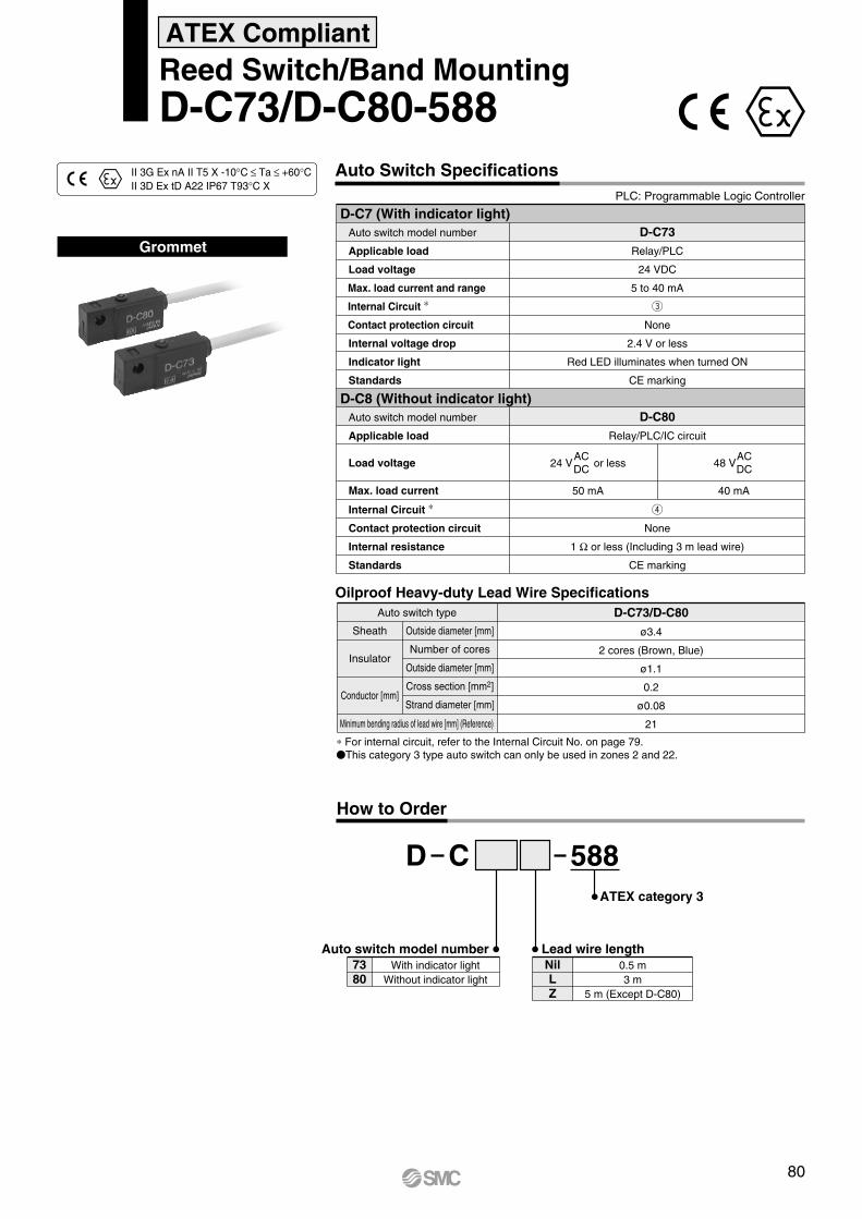
Auto Switch SpecificationsPLC: Programmable Logic Controller
D-C73
Relay/PLC
24 VDC
5 to 40 mA
e
None
2.4 V or less
Red LED illuminates when turned ON
CE marking
D-C80
Relay/PLC/IC circuit
24 V or less
50 mA
48 V
40 mA
r
None
1 Ω or less (Including 3 m lead wire)
CE marking
ACDC
ACDC
Reed Switch/Band MountingD-C73/D-C80-588
Grommet
CD 588ATEX category 3
Auto switch model number7380
With indicator lightWithout indicator light
Lead wire lengthNilLZ
0.5 m3 m
5 m (Except D-C80)
How to Order
ATEX Compliant
II 3G Ex nA II T5 X -10°C≤Ta≤+60°CII 3D Ex tD A22 IP67 T93°C X
Oilproof Heavy-duty Lead Wire SpecificationsD-C73/D-C80Auto switch type
ø3.4
2 cores (Brown, Blue)
ø1.1
0.2
ø0.08
21Minimum bending radius of lead wire [mm] (Reference)
Sheath
Insulator
Conductor [mm]
Outside diameter [mm]
Number of cores
Outside diameter [mm]
Cross section [mm2]
Strand diameter [mm]
∗ For internal circuit, refer to the Internal Circuit No. on page 79.This category 3 type auto switch can only be used in zones 2 and 22.
D-C7 (With indicator light) Auto switch model number
Applicable load
Load voltage
Max. load current and range
Internal Circuit ∗
Contact protection circuit
Internal voltage drop
Indicator light
Standards
D-C8 (Without indicator light) Auto switch model number
Applicable load
Load voltage
Max. load current
Internal Circuit ∗
Contact protection circuit
Internal resistance
Standards
80

Auto Switch Specifications
GrommetElectrical entry: Perpendicular
PLC: Programmable Logic Controller
D-A73, D-A73H (With indicator light)Auto switch model number
Applicable load
Load voltage
Load current range
Internal Circuit ∗
Contact protection circuit
Internal voltage drop
Indicator light
Standard
24 VDC
5 to 40 mA
e
None
2.4 V or less
Red LED illuminates when turned ON
CE marking
D-A73/D-A73H
Relay/PLC
D-A80/D-A80H
Relay/IC circuit/PLC
r
None
1 Ω or less (Including 3 m lead wire)
CE marking
D-A80, D-A80H (Without indicator light)Auto switch model number
Applicable load
Load voltage
Max. load current
Internal Circuit ∗
Contact protection circuit
Internal resistance
Standard
50 mA 40 mA
24 V or lessACDC
48 V ACDC
Reed Switch/Rail MountingD-A73(H)/D-A80(H)-588
AD 588ATEX category 3
Auto switch model number7380
With indicator lightWithout indicator light
Lead wire lengthNilLZ
0.5 m3 m
5 m (Except A 80)
How to Order
ATEX Compliant
II 3G Ex nA II T5 X -10°C≤Ta≤+60°CII 3D Ex tD A22 IP67 T93°C X
Electrical EntryNilH
PerpendicularIn-line
Oilproof Heavy-duty Lead Wire SpecificationsD-A73/D-A73H/D-A80/D-A80HAuto switch type
ø3.4
2 cores (Brown, Blue)
ø1.1
0.2
ø0.08
21Minimum bending radius of lead wire [mm] (Reference)
Sheath
Insulator
Conductor
Outside diameter [mm]
Number of cores
Outside diameter [mm]
Cross section [mm2]
Strand diameter [mm]
∗ For internal circuit, refer to the Internal Circuit No. on page 79.This category 3 type auto switch can only be used in zones 2 and 22.
81

Auto Switch Specifications
D-A54 (With indicator light)PLC: Programmable Logic Controller
Auto switch model number
Applicable load
Load voltage
Max. load current and range
Internal Circuit ∗
Contact protection circuit
Internal voltage drop
Indicator light
Standard
D-A54
Relay/PLC
24 VDC
5 to 50 mA
q
Built-in
2.4 V or less (up to 20 mA) / 3.5 V or less (up to 50 mA)
Red LED illuminates when turned ON
CE marking
D-A67 (Without indicator light)Auto switch model number
Applicable load
Load voltage
Max. load current and range
Internal Circuit ∗
Contact protection circuit
Internal resistance
D-A67
PLC/IC circuit
MAX. 24 VDC
30 mA
r
None
1 Ω or less (Including 3 m lead wire)
Standard CE marking
Reed Switch/Tie-rod MountingD-A54/D-A67-588
Grommet
AD 588ATEX category 3
Auto switch model number5467
With indicator lightWithout indicator light
Lead wire lengthNilLZ
0.5 m3 m
5 m (Except D-A67)
How to Order
ATEX Compliant
II 3G Ex nA II T5 X -10°C≤Ta≤+60°CII 3D Ex tD A22 IP67 T93°C X
Oilproof Heavy-duty Lead Wire SpecificationsD-A54/D-A67Auto switch type
ø4
2 cores (Brown, Blue)
ø1.22
0.3
ø0.08
24Minimum bending radius of lead wire [mm] (Reference)
Sheath
Insulator
Conductor
Outside diameter [mm]
Number of cores
Outside diameter [mm]
Cross section [mm2]
Strand diameter [mm]
∗ For internal circuit, refer to the Internal Circuit No. on page 79.This category 3 type auto switch can only be used in zones 2 and 22.
82

Auto Switch SpecificationsPLC: Programmable Logic Controller
D-A90/D-A90V
IC circuit/Relay/PLC
24 V or less
50 mA
r
None
1 Ω or less (Including 3 m lead wire)
CE marking
48 V or less
40 mA
D-A93/D-A93V
Relay/PLC
24 VDC
5 to 40 mA
e
None
D-A 93 —— 2.4 V or less (up to 20 mA)/3 V or less (up to 40 mA)D-A 93V —— 2.7 V or less
Red LED illuminates when turned ON
CE marking
ACDC
ACDC
Reed Switch/Direct MountingD-A90(V)/D-A93(V)-588
Grommet
AD 588ATEX category 3
Auto switch model number9390
With indicator lightWithout indicator light
Lead wire lengthNilLZ
0.5 m3 m
5 m (Except A90)
How to Order
ATEX Compliant
II 3G Ex nA II T5 X -10°C≤Ta≤+60°CII 3D Ex tD A22 IP67 T93°C X
Electrical EntryNilV
In-linePerpendicular
Oilproof Heavy-duty Lead Wire SpecificationsD-A90 (V)/D-A93 (V)Auto switch type
ø2.7
2 cores (Brown, Blue)
ø0.96
0.18
ø0.08
17Minimum bending radius of lead wire [mm] (Reference)
Sheath
Insulator
Conductor
Outside diameter [mm]
Number of cores
Outside diameter [mm]
Cross section [mm2]
Strand diameter [mm]
∗ For internal circuit, refer to the Internal Circuit No. on page 79.This category 3 type auto switch can only be used in zones 2 and 22.
D-A90, D-A90V (Without indicator light) Auto switch model number
Applicable load
Load voltage
Max. load current
Internal Circuit ∗
Contact protection circuit
Internal resistance
Standard
D-A93, D-A93V (With indicator light) Auto switch model number
Applicable load
Load voltage
Max. load current and
load current range
Internal Circuit ∗
Contact protection circuit
Internal voltage drop
Indicator light
Standard
83

Auto Switch Specifications
GrommetLead wire: Heavy-duty cord
PLC: Programmable Logic Controller
D-93ARelay/PLC
e
2.4V or less
Red LED illuminates when turned ON
CE marking
D-90ARelay/IC circuit/PLC
r
1 Ω or less (Including 3 m lead wire)
CE marking
50 mA
24 VDC
5 to 40 mA
Reed Switch/Direct MountingD-90A/D-93A-588
AD 588ATEX category 3
Auto switch model number9390
With indicator lightWithout indicator light
Lead wire lengthNilLZ
0.5 m3 m5 m
How to Order
ATEX Compliant
II 3G Ex nA II T5 X -10°C ≤ Ta ≤ +60°CII 3D Ex tD A22 IP67 T93°C X
Oilproof Heavy-duty Lead Wire SpecificationsD-90A/D-93AAuto switch type
ø3.4
2 cores (Brown, Blue)
ø1.1
0.2
ø0.08
21Minimum bending radius of lead wire [mm] (Reference)
Sheath
Insulator
Conductor
Outside diameter [mm]
Number of cores
Outside diameter [mm]
Cross section [mm2]
Strand diameter [mm]
∗ For internal circuit, refer to the Internal Circuit No. on page 79.This category 3 type auto switch can only be used in zones 2 and 22.
D-90A (Without indicator light) Auto switch model number
Applicable load
Load voltage
Max. load current
Internal Circuit ∗
Internal resistance
Standard
D-93A (With indicator light) Auto switch model number
Applicable load
Load voltage
Load current range
Internal Circuit ∗
Internal voltage drop
Indicator light
Standard
ACDC
24 V
84

Auto Switch Specifications
D-Z73 (With indicator light)PLC: Programmable Logic Controller
Auto switch model number
Applicable load
Load voltage
Max. load current and range
Internal Circuit ∗
Contact protection circuit
Internal voltage drop
Indicator light
Standard
D-Z73
Relay/PLC
24 VDC
5 to 40 mA
e
None
2.4 V or less (up to 20 mA)/3 V or less (up to 40 mA)
Red LED illuminates when turned ON
CE marking
D-Z80
Relay/PLC/IC circuit
r
None
1 Ω or less (Including 3 m lead wire)
CE marking
D-Z80 (Without indicator light)Auto switch model number
Applicable load
Load voltage
Max. load current
Internal Circuit ∗
Contact protection circuit
Internal resistance
Standard
50 mA 40 mA
Reed Switch/Direct MountingD-Z73/D-Z80-588
Grommet
ZD 588ATEX category 3
Auto switch model number7380
With indicator lightWithout indicator light
Lead wire lengthNilLZ
0.5 m3 m
5 m (Except D-Z80)
How to Order
ATEX Compliant
II 3G Ex nA II T5 X -10°C≤ Ta≤ +60°CII 3D Ex tD A22 IP67 T93°C X
Oilproof Heavy-duty Lead Wire SpecificationsD-Z73/D-Z80Auto switch type
ø2.7
2 cores (Brown, Blue)
ø1.1
0.18
ø0.08
17Minimum bending radius of lead wire [mm] (Reference)
Sheath
Insulator
Conductor
Outside diameter [mm]
Number of cores
Outside diameter [mm]
Cross section [mm2]
Strand diameter [mm]
∗ For internal circuit, refer to the Internal Circuit No. on page 79.This category 3 type auto switch can only be used in zones 2 and 22.
48 VACDC24 V or less
ACDC
85

Auto Switch Specifications
Oilproof Heavy-duty Lead Wire Specifications
D-E73A (With indicator light)PLC: Programmable Logic Controller
Auto switch model number
Applicable load
Load voltage
Max. load current and range
Internal Circuit ∗
Contact protection circuit
Internal voltage drop
Indicator light
Standard
D-E73A
D-E80A
Relay/PLC/IC circuit
r
None
1 Ω or less (Including 3 m lead wire)
CE marking
D-E73A/D-E80AAuto switch type
ø3.4
2 cores (Brown, Blue)
ø1.1
0.2
ø0.08
21Minimum bending radius of lead wire [mm] (Reference)
Sheath
Insulator
Conductor
Outside diameter [mm]
Number of cores
Outside diameter [mm]
Cross section [mm2]
Strand diameter [mm]
D-E80A (Without indicator light)Auto switch model number
Applicable load
Load voltage
Max. load current
Internal Circuit ∗
Contact protection circuit
Internal resistance
Standard
∗ For internal circuit, refer to the Internal Circuit No. on page 79.This category 3 type auto switch can only be used in zones 2 and 22.
50 mA 40 mA
Reed Switch/Direct MountingD-E73A/D-E80A-588
Grommet
E AD 588ATEX category 3
Auto switch model number7380
With indicator lightWithout indicator light
Lead wire lengthNilL
0.5 m3 m
How to Order
ATEX Compliant
II 3G Ex nA II T5 X -10°C≤ Ta≤ +60°CII 3D Ex tD A22 IP67 T93°C X
Relay/PLC
24 VDC
5 to 40 mA
e
None
2.4 V or less
Red LED illuminates when turned ON
CE marking
24 V or lessACDC 48 V
ACDC
86

GrommetElectrical entry: In-line
Left hand mounting Right hand mounting
D-R1D-R2
Auto Switch SpecificationsPLC: Programmable Logic Controller
Reed Switch/Direct MountingD-R73/D-R80-588
RD 588ATEX category 3
Auto switch model number7380
With indicator lightWithout indicator light
Lead wire lengthNilLZ
0.5 m3 m5 m
How to Order
ATEX Compliant
II 3G Ex nA II T5 X -10°C≤ Ta≤ +60°CII 3D Ex tD A22 IP67 T93°C X
Mounting12
Right hand mountingLeft hand mounting
Oilproof Heavy-duty Lead Wire Specifications
D-R73 (With indicator light)Auto switch model number
Applicable load
Load voltage
Load current range
Internal Circuit ∗
Internal voltage drop
Indicator light
Standard
D-R731/D-R732
Relay/PLC
24 VDC
5 to 40 mA
e
2.4 V or less
Red LED illuminates when turned ON
CE marking
D-R801/D-R802
Relay/IC circuit/PLC
50 mA
r
1 Ω or less (Including 3 m lead wire)
CE marking
D-R73/D-R80Auto switch type
ø3.4
2 cores (Brown, Blue)
ø1.1
0.2
ø0.08
21Minimum bending radius of lead wire [mm] (Reference)
Sheath
Insulator
Conductor
Outside diameter [mm]
Number of cores
Outside diameter [mm]
Cross section [mm2]
Strand diameter [mm]
D-R80 (Without indicator light)Auto switch model number
Applicable load
Load voltage
Max. load current
Internal Circuit ∗
Internal resistance
Standard
∗ For internal circuit, refer to the Internal Circuit No. on page 79.This category 3 type auto switch can only be used in zones 2 and 22.
24 VACDC
87

80 90
506380
100
Rotating angle
Size
Classification
Stan
dard
Sem
i-st
anda
rd
Symbol Single vane Double vane90
180270100190280
90°180°270°100°190°280°
90°——
100°——
WCRB155 B
MountingBL
BasicFoot
ATEX category 2
Shaft typeW Double shaft (long shaft with key and short shaft with four flats)
S
Vane typeSD
Single vaneDouble vane
Connecting port positionNilE
Side portsAxial ports
Thread PortNil-XF-XN
RcG
NPT
Standard
Bolt
B portA portB portA port
II 2Gc90°C (T5) Ta 5°C to 40°C110°C (T4) Ta 40°C to 60°C
Side ports Axial portsBody end of the short-shaft side
How to Order
Rotary Actuator: Vane Type
Sizes: 50, 63, 80, 100Series 55-CRB1ATEX Compliant
All other specifications are the same as the standard products Series CRB1. For details, refer to the WEB catalog or Best Pneumatics No. 4.
88

80
80
90
90
506380
100
Rotating angle
Size
Classification
Stan
dard
Sem
i-st
anda
rd
Symbol Single vane Double vane90
180270100190280
90°180°270°100°190°280°
90°——
100°——
W
W
Without magnet
With magnet
56 B
56
CRB1
CDRB1 B
MountingBL
BasicFoot
With auto switch unitBuilt-in magnet
Shaft typeW Double shaft (long shaft key & four chamfers)
S
S
Vane typeSD
Single vaneDouble vane
Connecting port positionNilE
Side portsAxial ports
Bolt
B portA portB portA port
Side ports Axial ports
ATEX category 3
II 3G84°C (T6) Ta 5°C to 40°C104°C (T4) Ta 40°C to 60°C
Body end of the short-shaft side
How to Order
Rotary Actuator: Vane Type
Sizes: 50, 63, 80, 100Series 56-CRB1ATEX Compliant
Refer to page 69 for applicable auto switches.
All other specifications are the same as the standard products Series CRB1. For details, refer to the WEB catalog or Best Pneumatics No. 4.
Thread PortNil-XF-XN
RcG
NPT
89
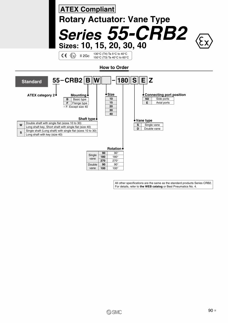
Size
55 CRB2 B
MountingBF
Basic typeFlange type
Rotation
Connecting port positionNilE
Side portsAxial ports
∗ F: Except size 40
Shaft type
W
S
Double shaft with single flat (sizes 10 to 30)Long shaft key, Short shaft with single flat (size 40)Single shaft (Long shaft) with single flat (sizes 10 to 30)Long shaft with key (size 40)
Vane type
Singlevane
Doublevane
90180270
90100
90°180°270°
90°100°
Standard
SD
Single vaneDouble vane
ATEX category 21015203040
130°C (T4) Ta 5°C to 40°C150°C (T3) Ta 40°C to 60°CII 2Gc
How to Order
Rotary Actuator: Vane Type
Sizes: 10, 15, 20, 30, 40Series 55-CRB2ATEX Compliant
All other specifications are the same as the standard products Series CRB2. For details, refer to the WEB catalog or Best Pneumatics No. 4.
180 S E ZW
90 a

56 B
56
CRB2
CDRB2 B
Size1015203040
MountingBF
BasicFlange
With auto switch unitBuilt-in magnet
Rotation
Singlevane
Doublevane
90180270
90100
90°180°270°
90°100°
∗ F: Except size 40
∗ Cannot be selected when mounting an auto switch
Shaft type
W
S∗
Double shaft with single flat (sizes 10 to 30)Long shaft with key, short shaft with single flat (size 40)Single shaft (Long shaft) with single flat (sizes 10 to 30)Long shaft with key (size 40)
Vane type
Withoutmagnet
With magnet
SD
Single vaneDouble vane
ATEX category 3
100°C (T5) Ta 5°C to 40°C120°C (T4) Ta 40°C to 60°CII 3G
How to Order
Rotary Actuator: Vane Type
Sizes: 10, 15, 20, 30, 40Series 56-CRB2ATEX Compliant
Refer to page 69 for applicable auto switches.
All other specifications are the same as the standard products Series CRB2. For details, refer to the WEB catalog or Best Pneumatics.
Connecting port positionNilE
Side portsAxial ports
180 S EW Z
W 180 S Z
91 b

Free mount type
ATEX category 2 Connecting port positionNilE
Side portsAxial ports
Standard
Rotation
Singlevane
Doublevane
90180270
90100
90°180°270°
90°100°
Vane typeSD
Single vaneDouble vane
Shaft type
W
S
Double shaft with single flat (sizes 10 to 30)Long shaft with key, short shaft with single flat (size 40)Single shaft (Long shaft) with single flat (sizes 10 to 30)Long shaft with key (size 40)
Size1015203040
130°C (T4) Ta 5°C to 40°C150°C (T3) Ta 40°C to 60°CII 2Gc
How to Order
Rotary Actuator: Free Mount Type
Sizes: 10, 15, 20, 30, 40Series 55-CRBU2ATEX Compliant
All other specifications are the same as the standard products Series CRBU2. For details, refer to the WEB catalog or Best Pneumatics No. 4.
55 CRBU2 180 S EW Z
92 a

Size
Free mount type
With auto switch unitBuilt-in magnet
NilE
Side portsAxial ports
Withoutmagnet
With magnet
Rotation
Singlevane
Doublevane
90180270
90100
90°180°270°
90°100°
Vane typeSD
Single vaneDouble vane
Shaft type
W
S∗
Double shaft with single flat (sizes 10 to 30)Long shaft with key, short shaft with single flat (size 40)Single shaft (Long shaft) with single flat (sizes 10 to 30)Long shaft with key (size 40)
ATEX category 3
100°C (T5) Ta 5°C to 40°C120°C (T4) Ta 40°C to 60°CII 3G
1015203040
How to Order
Rotary Actuator: Free Mount Type
Sizes: 10, 15, 20, 30, 40Series 56-CRBU2ATEX Compliant
Refer to page 69 for applicable auto switches.
All other specifications are the same as the standard products Series CRBU2. For details, refer to the WEB catalog or Best Pneumatics.
Connecting port position
∗ Cannot be selected when mounting an auto switch
CRBU256 180 SW E
56 CDRBU2 W 180 S
Z
Z
93 b

How to Order
55 S 20 90
55
CRQ2B
CDRQ2B S 20 90
Built-in magnet for auto switch
ATEX category 2
Size1015203040
Port thread
NilNilTFTNTT
Rc 1/8G 1/8
NPT 1/8NPTF 1/8
M5Size Port thread
10, 15
20, 30, 40
Rotation80° to 100°
170° to 190°90
180
Cushion
Without cushionRubber cushionAir cushion
—
—
10—
—
15
—
20
—
30
—
40SymbolSize
Cushion
Nil
C
Withoutmagnet
With magnet
Shaft typeSW
Single shaftDouble shaft
II 2Gc70°C (T6) Ta 0°C to 40°C90°C (T5) Ta 40°C to 60°C
Series 55-CRQ2
ATEX Compliant Compact Rotary ActuatorRack & Pinion Type
Refer to page 69 for applicable auto switches.
All other specifications are the same as the standard products Series CRQ2. For details, refer to the WEB catalog or Best Pneumatics No. 4.
94
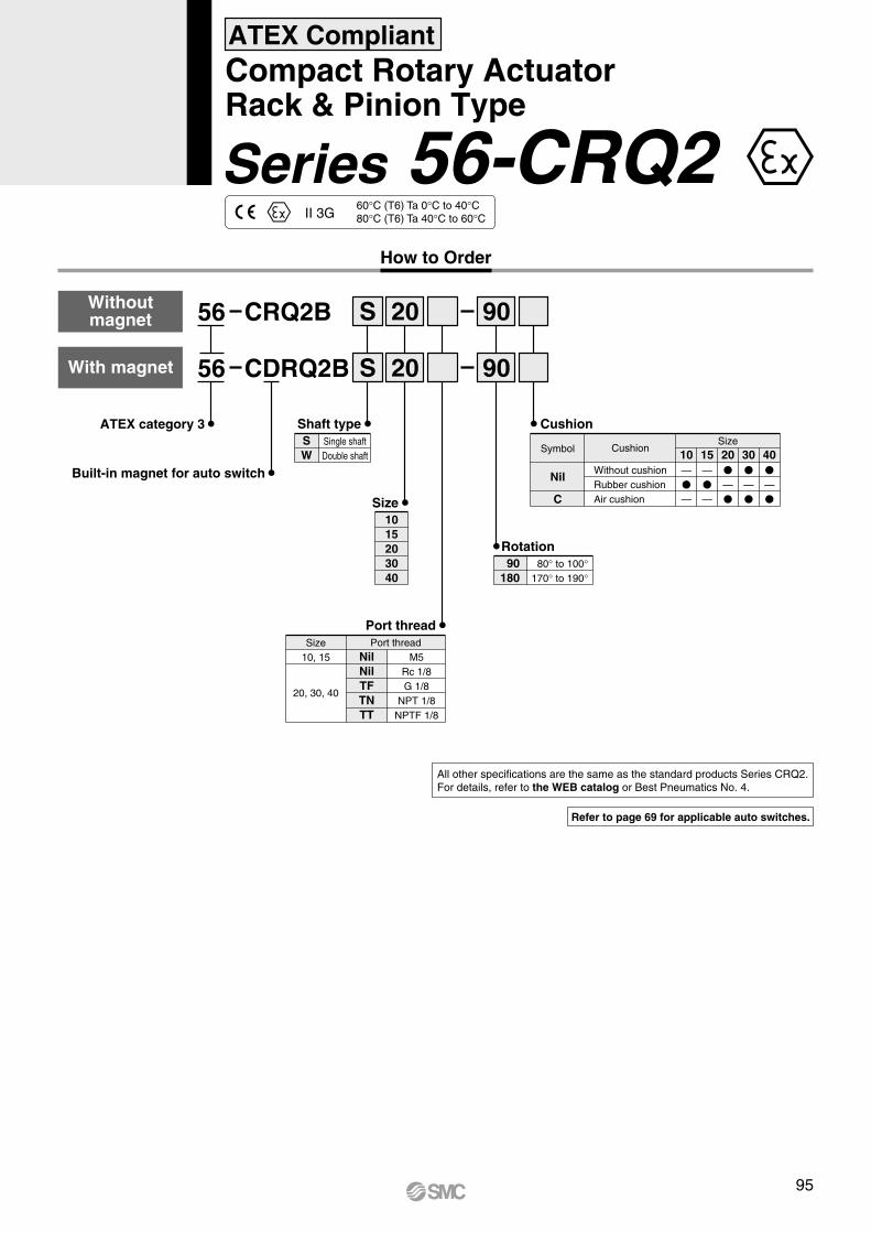
How to Order
56 S 20 90
56
CRQ2B
CDRQ2B S 20 90
Built-in magnet for auto switch
Size1015203040
Port thread
NilNilTFTNTT
Rc 1/8G 1/8
NPT 1/8NPTF 1/8
M5Size Port thread
10, 15
20, 30, 40
Rotation
Cushion
Withoutmagnet
With magnet
Shaft typeSW
Single shaftDouble shaft
ATEX category 3
II 3G60°C (T6) Ta 0°C to 40°C80°C (T6) Ta 40°C to 60°C
Series 56-CRQ2
ATEX Compliant Compact Rotary ActuatorRack & Pinion Type
Without cushionRubber cushionAir cushion
—
—
10—
—
15
—
20
—
30
—
40SymbolSize
Cushion
Nil
C
80° to 100°170° to 190°
90180
Refer to page 69 for applicable auto switches.
All other specifications are the same as the standard products Series CRQ2. For details, refer to the WEB catalog or Best Pneumatics No. 4.
95

ATEX Compliant Booster Regulator
Series 56-VBA10A to 43A
56-VBA 0440A
Port size
020304
1/4"3/8"1/2"
Port sizeVBA1AVBA2AVBA4A
Applicable seriesSymbol
Thread typeRcG
NPTNPTF
Thread type Note)
SymbolNilFNT
1/4, Handle-operated type1/4, Handle-operated type3/8, Handle-operated type1/2, Handle-operated type
3/8, Air-operated type1/2, Air-operated type
1/2, Max. operating pressure 1.6 Mpa
Pressure increase ratio: TwicePressure increase ratio: 2 to 4 times
Pressure increase ratio: Twice
Body size10A11A20A40A22A42A43A
ATEX category 3
Note) Thread type: NPT, NPTFUnder the new measurement law, the pressure unit of “psi” on the pressure gauges cannot be used in Japan.
Specifications
Pressure unit on the product name label and pressure gauge: psi
Standard product
Semi-standardSymbol
Nil
Z Note)
Note) Thread types apply to the IN, OUT, and EXH ports of the VBA1A and to the IN, OUT, EXH, and gauge ports of the VBA2A and VBA4A.The gauge ports of the VBA1A are Rc thread type regardless of the thread type indication.
OptionsOptionsNone
Pressure gaugeSilencer
High-noise reduction silencer Note)
Pressure gauge, SilencerPressure gauge, High-noise reduction silencer Note)
Elbow silencer Note)
Elbow high-noise reduction silencer Note)
Pressure gauge, Elbow silencer Note)
Pressure gauge, Elbow high-noise reduction silencer Note)
SymbolNilGNS
GNGSLNLS
GLNGLS
Note) Refer to “Combination of Thread Type and Options.”
10A11A
20A22A
40A42A43A
G
Combination of Thread Type and Options
Body sizeOptions Semi-standardThread
type NilNilFNT
NilFNT
NilFNT
——
——
——
——
——
——
——
N S GN GS LN LS GLN NilGLS -Z
RoHS
II 3 GD c T6 Ta 2°C to 50°C
All other specifications are the same as the standard products Series VBA.For details, refer to the WEB catalog or Best Pneumatics No. 5.
96
How to Order

How to Order
Specifications
Model
Rated pressure range
Pressure display range/Set pressure range
Withstand pressure
Pressure display resolution/Minimum unit setting
Applicable fluid
Power supply voltage
Current consumption
56-ISE700 to 1 MPa
−0.1 to 1 MPa
1.5 MPa
0.01 MPa
Air, Non-corrosive gas, Non-flammable gas
12 to 24 VDC±10%, Ripple (p-p) 10% or less (with power supply polarity protection)
55 mA or less (at no load)
ISE70 02 43
02N02F02
Rc1/4
NPT1/4
G1/4 (ISO1179)
Piping specifications
NilM
P
With display unit switching function Note 1)
Fixed SI unit Note 2)
Pressure unit: psi (Initial value)With display unit switching function Note 1)
Unit specifications
Nil
S
None
Lead wire with M12 connector (5 m),straight
L Lead wire with M12 connector (5 m),right-angled
Option 1
Nil
A
None
With bracket
Option 2
561MPa M
43
27
67
65
Fixed setting: (The pressure set point for switching the output signal is common to NPN and PNP.)NPN open collector 1 output (Pin no.: 4) + PNP open collector 1 output (Pin no.: 2)
Fixed settingPNP open collector 1 output (Pin no.: 4)
2 settingsNPN open collector 2 outputs (Pin no.: 2, 4)
2 settingsPNP open collector 2 outputs (Pin no.: 2, 4)
Output specifications
Note 1) Under the New Measurement Law, sales of switches with the unit switching function are not allowed for use in Japan. (Initial value: MPa)
Note 2) Fixed unit: Mpa
Series 56-ISE70
ATEX Compliant Digital Pressure Switch for Air
II 3G Ex nA II T5 X 0°C ≤ Ta ≤ 50°CII 3D tD A22 IP67 T53°C X
ATEX category 3
Follow the instructions given below when handling the pressure switch.• Operating temperature range is 0 to 50°C• Do not expose the pressure switch to heat radiation from a heat source located nearby. It can cause malfunction.• Do not expose the pressure switch/connector/cable to vibration and impact. Otherwise it can cause damage or malfunction.• Protect the product from direct sunlight or UV light using a suitable protective cover.• Do not disconnect the M12 connector while energized.• Use only an ATEX approved M12 connector.• For cleaning this product, use a clean and damp cloth, to prevent the buildup of an electrostatic charge.• Ground properly to prevent the buildup of an electrostatic charge.
All other specifications are the same as the standard products Series ISE70. For details, refer to the WEB catalog or Best Pneumatics No. 6.
Note) Mounting screws are not included.
97

How to Order
ISE75H
ISE75
15MPa
10MPa
02
Output specifications
02N02F02
Rc1/4
NPT1/4
G1/4 (ISO1179)
Piping specifications
Note 1) Under the New Measurement Law, sales of switches with the unit switching function are not allowed for use in Japan. (Initial value: MPa)
Note 2) Fixed unit: Mpa
NilM
P
With display unit switching function Note 1)
Fixed SI unit Note 2)
Pressure unit: psi (Initial value)With display unit switching function Note 1)
Unit specifications
Nil
S
None
Lead wire with M12 connector (5 m),straight
L Lead wire with M12 connector (5 m),right-angled
Option 1
Nil
A
None
With bracket
Option 2
M
02 43 M
43
43
Fixed setting: (The pressure set point for switching the output signal is common to NPN and PNP.)NPN open collector 1 output (Pin no.: 4) + PNP open collector 1 output (Pin no.: 2)
27
67
2 settingsNPN open collector 2 outputs (Pin no.: 2, 4)
2 settingsPNP open collector 2 outputs (Pin no.: 2, 4)
65 Fixed settingPNP open collector 1 output (Pin no.: 4)
Series 56-ISE75/75H
ATEX Compliant Digital Pressure Switch for General Fluids
II 3G Ex nA II T4 X -5°C ≤ Ta ≤ 50°CII 3D tD A22 IP67 T54°C X
56
ATEX category 3
56
Specifications
Model
Rated pressure range
Pressure display range/Set pressure range
Withstand pressure
Pressure display resolution/Minimum unit setting
Applicable fluid
Power supply voltage
Current consumption
56-ISE75 56-ISE75H
0.1 MPa
Fluid or gas that will not corrode SUS304, SUS430 and SUS630
12 to 24 VDC±10%, Ripple (p-p) 10% or less (with power supply polarity protection)
55 mA or less (at no load)
0 to 10 MPa
0.4 to 10 MPa
30 MPa
0 to 15 MPa
0.5 to 15 MPa
45 MPa
Follow the instructions given below when handling the pressure switch.• Operating temperature range is − 5 to 50°C• Do not expose the pressure switch to heat radiation from a heat source located nearby. It can cause malfunction.• Do not expose the pressure switch/connector/cable to vibration and impact. Otherwise it can cause damage or malfunction.• Protect the product from direct sunlight or UV light using a suitable protective cover.• Do not disconnect the M12 connector while energized.• Use only an ATEX approved M12 connector.• For cleaning this product, use a clean and damp cloth, to prevent the buildup of an electrostatic charge.• Ground properly to prevent the buildup of an electrostatic charge.
All other specifications are the same as the standard products Series ISE75/ISE75H.For details, refer to the WEB catalog or Best Pneumatics No. 6.
Note) Mounting screws are not included.
98

VND56 15AAir operated 2 D S0
Valve type
Body optionNil
Note) SStandard (Copper alloy)
Stainless steel body
Note) Threaded type only
OptionsNil
Note) BL
Note) BL
NoneWith bracket
With indicator light(visual verification of operation)With bracket and indicator light(visual verification of operation)
Valve size Port size
Orifice dia.(mm)
SymbolSymbol
SymbolN.C. N.O. N.C.
Port sizeRc
ø15
ø7
ø20
2
1
0 2 4
3ø254
ø325
ø406
ø507
6A8A10A10A15A20A25A32A32F40A40F50A50F
Note) Brackets (for valve size 1/2/3/4 only) will be assembled at the time of shipment.Bracket part no.
Valve size 1: VN1-A16 (with thread)Valve size 2 to 4: VN-16
2 to 4
Thread typeNilFNT
RcGNPTNPTF
ATEX category 3
How to Order
Series 56-VND
ATEX Compliant 2 Port Steam ValveSteam Valve
II 3G TX-5°C ≤ Ta ≤ 60°C
All other specifications are the same as the standard products Series VND. For details, refer to the WEB catalog or Best Pneumatics No. 7.
———
——————————
11
2
1 81 43 83 81 23 4
1 4
11 2
11 4 B Flange
11 2 B Flange
2 B Flange
99
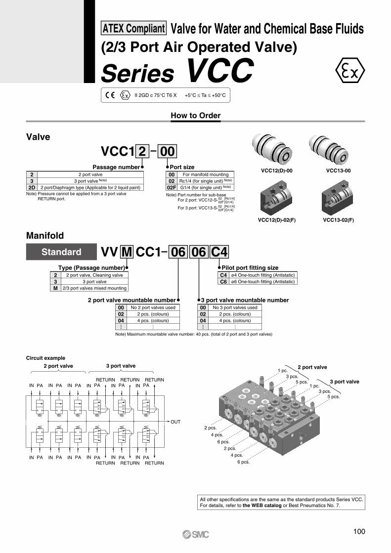
1 pc.3 pcs.
5 pcs.1 pc.
3 pcs.5 pcs.
2 port valve
3 port valve
2 pcs.
4 pcs.
6 pcs.2 pcs.
4 pcs.
6 pcs.
PAIN
PAIN
PAIN
PAINRETURN
PAIN
RETURNPAINPAIN
PAIN
3 port valve2 port valve
RETURNPAIN
RETURNPAIN
RETURNPAIN
RETURN
OUT
PAIN
Circuit example
Valve
2 00VCC1Port size
For manifold mountingRc1/4 (for single unit) Note)
G1/4 (for single unit) Note)
0002
02F
Passage number2 port valve
3 port valve Note)
2 port/Diaphragm type (Applicable for 2 liquid paint)
23
2D
Manifold
06VV CC1M 06 C4Standard
Type (Passage number)2 port valve, Cleaning valve
3 port valve2/3 port valves mixed mounting
23M
3 port valve mountable numberNo 3 port valves used
2 pcs. (colours)4 pcs. (colours)
000204
… …
Pilot port fitting sizeø4 One-touch fitting (Antistatic)ø6 One-touch fitting (Antistatic)
C4C6
VCC12(D)-00 VCC13-00
VCC12(D)-02(F) VCC13-02(F)
2 port valve mountable numberNo 2 port valves used
2 pcs. (colours)4 pcs. (colours)
000204
… …
Note) Maximum mountable valve number: 40 pcs. (total of 2 port and 3 port valves)
Note) Part number for sub-baseFor 2 port: VCC12-S-
For 3 port: VCC13-S-
0202F
[Rc1/4][G1/4]
0202F
[Rc1/4][G1/4]
Note) Pressure cannot be applied from a 3 port valve RETURN port.
II 2GD c 75°C T6 X +5°C ≤ Ta ≤ +50°C
Series VCC
ATEX Compliant Valve for Water and Chemical Base Fluids(2/3 Port Air Operated Valve)
How to Order
All other specifications are the same as the standard products Series VCC. For details, refer to the WEB catalog or Best Pneumatics No. 7.
100

OUT
Cleaning valve
Cleaning valve
Cleaning valve
Gate valve
Circuit example
RETURNPAIN
RETURNPAINPAIN
PAIN
2/3 port valve
PAIN
Gate/Cleaning valve
PAIN
PAPAIN
Gate valve RETURNPAIN
RETURNPAIN
RETURNPAIN
RETURN
OUT
PAIN
How to Order
02VV CC1 GM 06 C4 04With gate valve
Passage number2 port valve, Cleaning valve
2/3 port valves mixed mounting2M
Gate valve and cleaning valve mountable numberCleaning valve (2 port valve): 1 pc. + Gate valve: 1 pc.Cleaning valve (2 port valve): 3 pcs. + Gate valve: 1 pc.Cleaning valve (2 port valve): 5 pcs. + Gate valve: 1 pc.
020406
2 port valve mountable numberNo 2 port valves used
2 pcs. (colours)4 pcs. (colours)
000204
… …
3 port valve mountable numberNo 3 port valves used
2 pcs. (colours)4 pcs. (colours)
000204
… …
∗ The gate valve and cleaning valve (2 port valve) are not included. They are ordered separately. (Gate valve is equivalent to 2 port valve.)
∗ When cleaning valve number is an even number, use the blanking plug for 2 port valve.
Pilot port fitting sizeø4 One-touch fitting (Antistatic)ø6 One-touch fitting (Antistatic)
C4C6
Note) Maximum mountable valve number: 40 pcs.(total of 2 port, 3 port and gate valves)
Manifold
All other specifications are the same as the standard products Series VCC. For details, refer to the WEB catalog or Best Pneumatics No. 7.
101
Series VCCATEX Compliant Valve for Water and Chemical Base Fluids

Port size1/81/41/81/41/43/83/81/21/23/41
Body class
2
4
5
6
3
1
Symbol0102010202030304040610
Port size
Thread typeRc
NPTG
SymbolNilNF
Thread type
Body class
LVA55 2 0 02 A
Symbol123456
Body class123456
Orifice dia.ø2ø4ø8ø12ø20ø22
Valve type012
N.C.N.O.
Double acting
Note) Refer to “Series Variations” in the table below for valve type combinations.
NoneWith flow rate adjustment
With bypass (PFA body only)With flow rate adjustment & bypass (PFA body only)
With indicator
Nil1234
Options
Material
BodyApplicable option
SUS
PPS
PFA
SUS
SUS
PFA
PPS
PPS
PFA
Diaphragm
PTFE
PTFE
PTFE
NBR
EPR
PTFE
NBR
EPR
PTFE
Note
Hydrofluoric acid compatibleOnly 55-LVA40
Ammonium hydroxide compatible55-LVA20 to 40
—
55-LVA10 to 40
55-LVA10 to 40
55-LVA10 to 40
55-LVA10 to 50
55-LVA20 to 40
55-LVA10 to 50
Actuator sectionEnd plate
PPS—
PPS
PPS
PPS—
PPS—
PVDF
PPS
PPS
PPS
Symbol
A
B
C
D
E
F
G
H
N
1
2
3
4
ATEX category 2
How to Order Valves (Single Type)
Series 55-LVA
ATEX Compliant Air operated typeThreaded Type
55-LVA10 and 55-LVA12 II 2G c IIB T6 X Ta 0°C to +50°C II 2G c IIB TXX Ta 0°C to +60°C
Special condition X "Protect from impact"
55-LVA2, 55-LVA3, 55-LVA4, 55-LVA5,55-LVA6 and 55-LVA200
II 2GD c IIB 80°C T6 X Ta 0°C to +50°CII 2GD c IIB TXX Ta 0°C to +60°C
Special condition X "Protect from impact"
N.C.
N.C.
N.O. Doubleacting
Double acting
A
PA
B AB
PB
AB
PA
PB
A
PA
B AB
PA
PB
N.C. Double acting
N.C. Double acting
PA
B A
N.C.
PA
B A
PA
PB
B A
PA
B A
PA
PB
B A
Model 55-LVA10 55-LVA20 55-LVA30 55-LVA40 55-LVA60
1/8 1/4
ø2
1/8 1/4
ø4
1/4 3/8
ø8
3/8 1/2
ø12 ø2255-LVA50
1/2 3/4
ø20
1
Series Variations
N.C.
N.C.
N.O.
Double acting
Double acting
N.C.
Double acting
N.C.
Double acting
N.C.
—
—
—
—
—
—
—
—
—
—
—
—
—
—
—
—
—
—
—
—
—
—
—
—
—
—
—
—
—
—
—
—
—
—
—
—
—
—
—
—
—
—
—
—
—
—
—
—
—
—
—
—
—
—
Basic
With flow rate adjustment
With by-pass
With flow rate adjustment & by-pass
With indicator
Type
Body materialOnly PFA
Body materialOnly PFA
PPSPFA
Valve type
SUS316
Symbol
Body material Note)
Note) Refer to the “Material” table for the applicable optional body materials.
Model 55-LVA10 55-LVA20 55-LVA30
0 to 500 to 1000 to 500 to 60
55-LVA40 55-LVA50 55-LVA60Fluid temperature (°C)
Ambient temperature (°C)
Temperature class T6Temperature class TXTemperature class T6Temperature class TX
Specifications
Note) The manifold type is not available with ATEX certification
Orifice dia.Port size
All other specifications are the same as the standard products Series LVA. For details, refer to the WEB catalog or Best Pneumatics No. 7.
Note) Refer to “Variations” in the table below for option combinations. Options can not be combined each other.
102

LVA55 2 0 0
Body classSymbol
2Body class
2Orifice dia.
ø4
Valve type0 N.C.
Thread typeRc
NPT
SymbolNilN
Thread type
MaterialBody Actuator section DiaphragmSymbol
PFA PPS PTFEC
Port sizePort size
1/4Symbol
02
02 CATEX category 2
How to Order Valves
Series 55-LVA
ATEX Compliant Air operated typeThreaded Type
55-LVA10 and 55-LVA12 II 2G c IIB T6 X Ta 0°C to +50°C II 2G c IIB TXX Ta 0°C to +60°C
Special condition X "Protect from impact"
55-LVA2, 55-LVA3, 55-LVA4, 55-LVA5,55-LVA6 and 55-LVA200
II 2GD c IIB 80°C T6 X Ta 0°C to +50°CII 2GD c IIB TXX Ta 0°C to +60°C
Special condition X "Protect from impact"
Note) The manifold type is not available with ATEX certification
All other specifications are the same as the standard products Series LVA. For details, refer to the WEB catalog or Best Pneumatics No. 7.
103

3 1 1 0 0355 PA
Actuation
Symbol
NilN
Options
Options
NoneWith silencer
Applicable actuation
Automaticallyoperated type
Air operated type
—
Thread type
Symbol35
Body sizeBody size
3/8 standard1/2 standard
Symbol
12
Diaphragm material
Diaphragm material
PTFENBR
Automaticallyoperated type
Applicable actuation
Air operated type
—
Symbol12
Liquid contact body materialBody material
ADC12 (Aluminum)SCS14 (Stainless steel)
Symbol
030406
Port size
Port size
3/8"1/2"3/4"
Applicable modelPA3000
——
PA5000—
ATEX category 2
SymbolNilNFT
TypeRc
NPTG
NPTF
Symbol03
ActuationAutomatically operated type
Air operated type
∗ Dimensions are the same as the standard products.
For 55-PA30: II 2 GD c T6 Ta 0°C to +60°CFor 55-PA33: II 2 GD c T5 Ta 0°C to +60°CFor 55-PA5: II 2 GD c T6 Ta 0°C to +60°CFor 55-PA53: II 2 GD c T6 Ta 0°C to +60°C
How to Order
All other specifications are the same as the standard products Series PA3000/5000. For details, refer to the WEB catalog or Best Pneumatics No. 7.
Series 55-PA3000/5000
ATEX Compliant Process PumpAutomatically operated type (Internal switching type)/Air operated type (External switching type)
∗ A silencer of 2504-002 (NPT: 2504-N002) is provided.
104
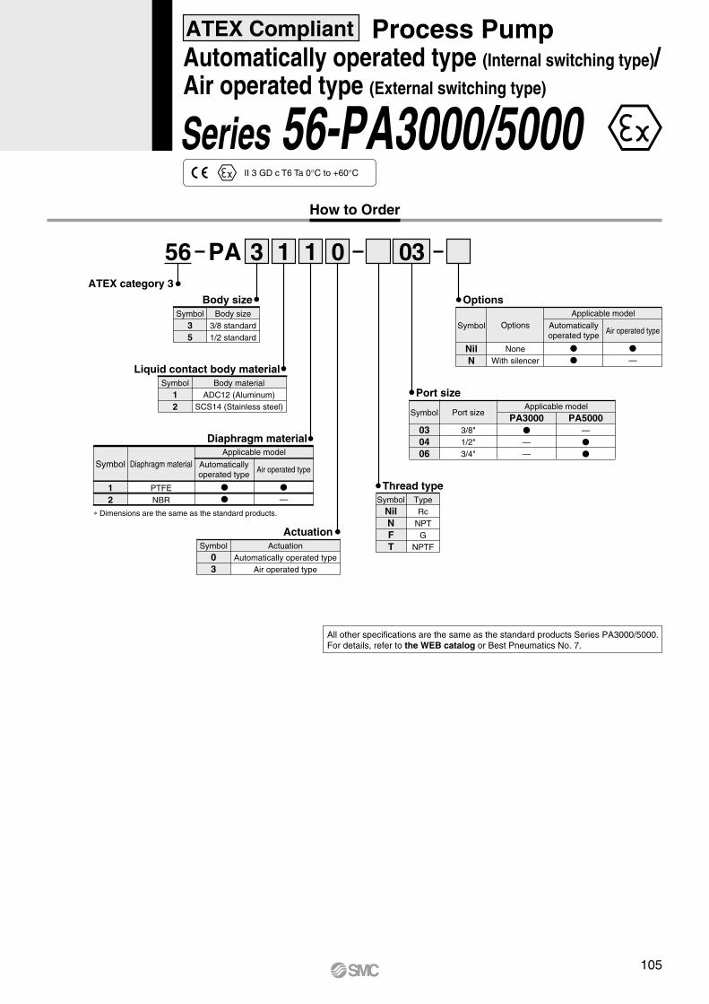
3 1 1 0 0356 PA
Actuation
Symbol
NilN
Options
Options
NoneWith silencer
Applicable model
Automaticallyoperated type
Air operated type
—
Thread type
Symbol35
Body sizeBody size
3/8 standard1/2 standard
Symbol
12
Diaphragm material
Diaphragm material
PTFENBR
Automaticallyoperated type
Applicable model
Air operated type
—
Symbol12
Liquid contact body materialBody material
ADC12 (Aluminum)SCS14 (Stainless steel)
Symbol
030406
Port size
Port size
3/8"1/2"3/4"
Applicable modelPA3000
——
PA5000—
ATEX category 3
SymbolNilNFT
TypeRc
NPTG
NPTFSymbol03
ActuationAutomatically operated type
Air operated type
∗ Dimensions are the same as the standard products.
Series 56-PA3000/5000II 3 GD c T6 Ta 0°C to +60°C
How to Order
ATEX Compliant Process PumpAutomatically operated type (Internal switching type)/Air operated type (External switching type)
All other specifications are the same as the standard products Series PA3000/5000. For details, refer to the WEB catalog or Best Pneumatics No. 7.
105

Pneumatic-Pneumatic Positioner
Series 55-IP5000/5100
0 0100055 IP5
Ambient temperature
Input pressure
Indication of opening Note)
0
1
0.2 to 1.0 MPa (Standard)1/2 split
0.02 to 0.06, 0.06 to 0.1 MPa
Pressure gauge/Air portNilNF
Rc (Standard)NPT
G
NilTL
−20 to 80°C (Standard)−5 to 100°C (High temperature)−30 to 60°C (Low temperature)
01
Not providedIndicated
ATEXcategory 2
Positioner type000100
Lever typeRotary type
Pressure gauge (SUP, OUT1)0123
Not provided0.2 MPa0.3 MPa1.0 MPa
Note) Please refer to table below
Accessories Note 1)
Nil
A
B
CD
E
F
Without accessory(standard)
With ø0.7 output restrictorintegrated pilot valve
With ø1.0 output restrictorintegrated pilot valve
With fork lever type fitting MWith fork lever type fitting S
With lever unit for a 35 to 100 mm stroke
With lever unit for a 50 to 140 mm stroke
Only for IP5100
Only for IP5100 Note 2)
Note 1) If multiple accessories are required, they should be indicated in alphabetical order.ex. 55-IP5000-010-AD
Note 2) For ''E'' and ''F'', standard lever is not provided.
Classification
II 2GD c T4II 2GD c T5II 2GD c T6
Low temperature55-IP500-L-
––
-30°C ≤ Ta ≤ 60°C
Standard55-IP500--
–-20°C ≤ Ta ≤ 80°C-20°C ≤ Ta ≤ 60°C
High temperature55-IP500-T--5°C ≤ Ta ≤ 100°C-5°C ≤ Ta ≤ 80°C-5°C ≤ Ta ≤ 60°C
Ambient temperature range
Specifications
II 2GDc T4-T6
How to Order
ATEX Compliant
Note) 55-IP5000 is available only with option ''0'' (no indication).
With standard lever (10 to 85 mm stroke) for IP5000
Common to IP5000 and IP5100 small capacity actuators
All other specifications are the same as the standard products Series IP5000/5100.For details, refer to the WEB catalog or Series IP5000/5100 (CAT.ES60-13).
106

II 3GD c T4II 3GD c T5II 3GD c T6
Low temperature56-IP500-L-
––
-30°C ≤ Ta ≤ 60°C
Standard56-IP500--
–-20°C ≤ Ta ≤ 80°C-20°C ≤ Ta ≤ 60°C
High temperature56-IP500-T--5°C ≤ Ta ≤ 100°C-5°C ≤ Ta ≤ 80°C-5°C ≤ Ta ≤ 60°C
Classification
Ambient temperature range
0 0100056 IP5
Ambient temperature
Input pressure
Indication of opening Note)
0
1
0.2 to 1.0 MPa (Standard)1/2 split
0.02 to 0.06, 0.06 to 0.1 MPa
Pressure gauge / Air portNilNF
Rc (Standard)NPT
G
NilTL
−20 to 80°C (Standard)−5 to 100°C (High temperature)−30 to 60°C (Low temperature)
01
Not providedIndicated
ATEX category 3
Positioner type000100
Lever typeRotary type
Pressure gauge (SUP, OUT1)0123
Not provided0.2 MPa0.3 MPa1.0 MPa
Accessories Note 1)
Nil
A
B
CD
E
F
Without accessory(standard)
With ø0.7 output restrictorintegrated pilot valve
With ø1.0 output restrictorintegrated pilot valve
With fork lever type fitting MWith fork lever type fitting S
With lever unit for a 35 to 100 mm stroke
With lever unit for a 50 to 140 mm stroke
With standard lever (10 to 85 mm stroke) for IP5000
Common to IP5000 and IP5100 small capacity actuators
Only for IP5100
Only for IP5100 Note 2)
Note 1) If multiple accessories are required, they should be indicated in alphabetical order.ex. 56-IP5000-010-AD
Note 2) For ''E'' and ''F'', standard lever is not provided.
Specifications
II 3GDc T4-T6
Note) Please refer to table below
How to Order
Pneumatic-Pneumatic Positioner
Series 56-IP5000/5100ATEX Compliant
All other specifications are the same as the standard products Series IP5000/5100.For details, refer to the WEB catalog or Series IP5000/5100 (CAT.ES60-13).
Note) 55-IP5000 is available only with option ''0'' (no indication).
107

4 to 20 mADC (Standard) Note1)
235 ± 15Ω (4 to 20 mADC)0.14 to 0.7 MPa
Within ± 0.5% F.S.Within 0.1% F.S./°C
Note 3) 80 L/min (ANR) or more (SUP = 0.14 MPa)Note 3) Within 5 L/min (ANR) (SUP = 0.14 MPa)
−20°C to 80°C (T5)−20°C to 60°C (T6)
ATEX intrinsically safe explosion proof structure
Approval No. KEMA 03 ATEX1119
1/4 NPT female screwM20 x 1.5
Aluminium diecast for the bodyApprox. 2.4 kg
JIS F8007 IP55 (Conform to IEC 60529)
Ui ≤ 28V, Ii ≤ 125mA, Pi ≤ 1.2W, Ci ≤ OnF, Li ≤ OmH
IP6 000ATEX category 2
Positioner type000100
Lever typeRotary type
Pressure gauge (SUP, OUT1)123
0.2 MPa0.3 MPa1.0 MPa
Accessories Note)
10 0 X14
TypeItem
Input currentInput resistanceSupply air pressure
Standard stroke
SensitivityLinearityHysteresisRepeatabilityThermal coefficientOutput flow rateAir consumptionAmbient and using fluid Temperature
Explosion protected Construction
Classification of degree of protectionParameters(Current circuit)
Air connection portElectric wiring connection portMaterialWeight
IP6000Lever type lever
10 to 85 mm(External lever allowable runout angle 10° to 30°) 60° to 100° Note 2)
IP6100Rotary type cam
Single acting Double acting Single acting Double acting
Within 0.1% F.S.Within ± 1% F.S.Within 0.75% F.S.
( II 2G Ex ib II C T5/T6)
Within 0.5% F.S.Within ± 2% F.S.Within 1% F.S.
0344
Nil
A
B
CD
E
F
G
Without accessory (standard)
With compensation spring (A)
With ø0.7 output restrictorintegrated pilot valve
With ø1.0 output restrictorintegrated pilot valve
With fork lever type fitting MXWith fork lever type fitting SX
With lever unit for a 35 to 100 mm stroke
With lever unit for a 50 to 140 mm stroke
With standard lever (10 to 85 mm stroke) for IP6000
Common to IP6000 and 6100 small capacity actuators
Only for IP6100
Only for IP6000
Common to IP6000 and 6100Note) If multiple accessories are required, they should be indicated in alphabetical
order.ex. IP6000-011-AG-X14
Note 1) 1/2 split range is possible with the standard type (by adjusting the span).Note 2) The stroke is adjustable in 0° to 60° and 0° to 100°.Note 3) Standard air (JIS B0120): temp. 20°C, absolute press. 760 mmHg, ratio humidity 65%.
How to Order
II 2G Ex ib IIC T5/T6
Specifications
(Lever type/Rotary type)
Series IP6000-X14/6100-X14ATEX Compliant Electro-Pneumatic Positioner
All other specifications are the same as the standard products Series IP6000/6100.For details, refer to the WEB catalog or Series IP6000/6100 (CAT.ES60-11).
108

MPabar
SMC
MPabar
SMC
Zero adjusting knob
SMC Corporation 1-16-4 Shinbashi Minatoku Tokyo 105-8659 Japan
KEMA No.03ATEX1119EExIb CT5 Ta 80CEExIb CT6 Ta 60C
UI 28V II 125mA P 1.2V CI 0nf LI 0nH20** MADE IN JAPAN
Serial No.*****SUPPLY 0.14 to 0.7MPa(1.4 to 7bar )MODEL NO. IP6*00-0*0-*-X14-*
INPUT 0/4 to 20mADC
SMC ELECTRO-PNEUMATIC POSITIONER
MPabar
SMC
MPabar
SMC
1104035
65
22.5
4220
5046
166.1
5
130 10
015
35
15168
122
125
150
125=180
3511
38
53
110
302
14
B
B
NP
E
Pressure gauge port 2 x Rc1/8
Mark ''M'' means that this port is ''M'' thread
(OUT2.1/4NPT)
E
SPA
N
MA
OUT2
Span adjusting knob
M
2 x M8 x 1.25 depth 12(Female thread for mounting, side position)
A4 x M8 x 1.25 depth 12(Female thread for mounting, backside)
M20 x 1.5Porting for electrical connection
Plugged
OUT1.1/4NPT
SUP.1/4NPT
A
E
OUT2
PE
IP6000MODEL
At accessory “E”: 110At accessory “F”: 110At accessory "E": 195At accessory "F": 275
Dimensions/IP6000
IP6000-00--X14 (Lever type)
Series IP6000-X14ATEX Compliant Electro-Pneumatic Positioner/Lever type
109

24
2163
(39)
770
(46) M
Pa
bar
SM
CM
Pa
bar
SM
CM
Pa
bar
SM
CM
Pa
bar
SM
C
42
22.5
65
3540 110
2050
46
122
=180125
130 10
035
15
15168
4411
6
1135
38
53
Positioner body
Hold spring
Fork lever type fitting
Fork pin unit
Main shaft of actuator
C-C
CC
M6 x 1
B
NP
E
M
OUT1.1/4NPT
SUP.1/4NPT
A
E
PE
MO
DE
LIP6100
90 o
60 o
30 o30 o
60 o
90 o
Oo
OUT2
DA
0
SPAN
E
MA
OUT2
M20 x 1.5Porting for electrical connection
B
Zero adjusting knob
(OUT2.1/4NPT)Plugged
Pressure gauge port 2 x Rc1/8
A4 x M8 x 1.25 depth 12(Female thread for mounting, backside)
2 x M8 x 1.25 depth 12(Female thread for mounting, side position)
SMC Corporation 1-16-4 Shinbashi Minatoku Tokyo 105-8659 Japan
KEMA No.03ATEX1119EExIb CT5 Ta 80CEExIb CT6 Ta 60C
UI 28V II 125mA P 1.2V CI 0nf LI 0nH20** MADE IN JAPAN
Serial No.*****SUPPLY 0.14 to 0.7MPa(1.4 to 7bar )MODEL NO. IP6*00-0*0-*-X14-*
INPUT 0/4 to 20mADC
SMC ELECTRO-PNEUMATIC POSITIONER
Dimension of optional fork leverassembly type “MX”
( ) Shows dimension of fork lever assembly type ''SX''
Mark ''M'' means that this port is ''M'' thread
Dimensions/IP6100
IP6100-00--X14 (Rotary type)
Series IP6100-X14ATEX Compliant Electro-Pneumatic Positioner/Rotary type
110

Accessories Note 1)
Symbol AccessoriesApplicable model
NilABCDEFGH
Without accessoryWith ø0.7 output restrictor integrated pilot valve Note 2)
With ø1.0 output restrictor integrated pilot valve Note 2)
With fork lever type fitting M Note 3)
With fork lever type fitting S Note 4)
With lever unit for a 35 to 100 mm stroke Note 5)
With lever unit for a 50 to 140 mm stroke Note 5)
With compensation spring (A) Note 6)
With external scale plate
IP8000-X14
——
—
IP8100-X14
——
Positioner typeElectro-pneumatic lever typeElectro-pneumatic rotary type
000100
Option Note 7)
000IP8 0 X14
ATEX directive compliance and connection
X14
ATEX directive category 2Intrinsically safe explosion-proof itemAir connection port: 1/4 NPTConduit connection port: M20 x 1.5With blue cable gland
Note 1) If multiple accessories are required, they should be indicated in alphabetical order.ex. IP8100-010-AG
Note 2) “A” is applied to approx 90 cm3-capacity actuator.“B” is applied to approx 180 cm3-capacity actuator.
Note 3) Fork lever-type fitting MX (Connection thread: M6 x 1) for IP8100-00--X14.
Note 4) Fork lever-type fitting SX (Connection thread: M6 x 1) for IP8100-00--X14.
Note 5) Standard lever is not attached.Note 6) It is to be used together with “A” or “B” when tending to overshoot by the
use of “A” or “B”. It is mounted to the body as a replacement of the standard compensation spring.
Note 7) Combination of “L” and “W” is not available.
ATEX Directive IntrinsicallySafe Explosion Proof 1 0
Pressure gaugePressure
Not provided0.2 MPa0.3 MPa1.0 MPa
Symbol0123
NilLW
Option
—Low temperature (−40 to 60°C)With internal opening indicator plate
Applicable modelIP8000-X14
—
IP8100-X14
Symbol
II 2G Ex ib IIC T5/T6
How to Order
(Lever type/Rotary type)
Series IP8000-X14/8100-X14ATEX Compliant Electro-Pneumatic Positioner
All other specifications are the same as the standard products Series IP8.For details, refer to the WEB catalog or Series IP8 (CAT.ES60-18).
111

Accessories Note 1)
Symbol AccessoriesApplicable model
NilCDEFHW
NoneWith fork lever type fitting MWith fork lever type fitting SFor stroke 35 to 100 mm with lever unit Note 2)
For stroke 50 to 140 mm with lever unit Note 2)
With external scale plateBody with LCD window
IP8001
——
—
IP8101
——
TypeSmart lever typeSmart rotary type
001101
123
0.2 MPa0.3 MPa1.0 MPa
——
Pressure gauge NoteConnection
NilM Note)
N1
2 Note)
34
5 Note)
6
Air Electric Rc1/4Rc1/4Rc1/4
1/4NPT1/4NPT1/4NPT
G1/4G1/4G1/4
G1/2M20 x 1.51/2NPT
G1/2M20 x 1.51/2NPT
G1/2M20 x 1.51/2NPT
ATEX temperature
NilT6
SymbolApplicable model
IP8101IP8001T4
T5/T6
ATEXtemperature
001IP852 0 3 4
Specifications
4Intrinsically safe explosion proof (ATEX) + output function + HART communication
Note) When the symbol is M, 2, or 5 for 52- ATEX directive items, a blue cable gland is included with the electrical connection.
Symbol
SymbolPressure
gaugeApplicable modelIP8001 IP8101
Note 1) If two or more accessories are required, the part numbers should be given in alphabetical order.ex. 52-IP8101-034-CH
Note 2) Standard lever is not attached.
ATEX directive complianceATEX directive category 1
Intrinsically safe explosion-proof52
ATEX Directive IntrinsicallySafe Explosion Proof
(Lever type/Rotary type)
Series 52-IP8001/8101ATEX Compliant Smart Positioner
II 1 G Ex ia IIC T4/T5/T6 GaT4/T5: Ta = -20°C to 80°C T6: Ta = -20°C to 60°C
How to Order
All other specifications are the same as the standard products Series IP8.For details, refer to the WEB catalog or Series IP8 (CAT.ES60-18).
112

Series 56-IP200/210
ATEX Compliant
Cylinder Positioner
0 056 IP2
Model01
StandardOutside tube fixed to the main body
Stroke 25 to 300 mm
Temperature and MaterialNilTL
S
Standard –5°C to 60°CHigh –5°C to 100°CLow –30°Cto 60°C
Feedback spring and zeroadjustment screw made in stainless steel
ATEX category 3
II 3GD 100°C (T5)II 3GD 60°C (T6)
Low temp. model56-IP20--L
—–30°C to 60°C
—–5°C to 60°C
–5°Cto 100°C—
Standard model56-IP20-
High temp. model56-IP20--TClassification
Ambient temperature range
56-IP200/2100.3 to 0.7 MPa0.02 to 0.1 MPa
Rc 1/4 (standard)Rc 1/8
Less than ± 2% F.S.Less than 1% F.S.Less than 1% F.S.
Less than 0.5% F.S.18 L/min (ANR) or less (SUP=0.5 MPa)
200 L/min (ANR) or more (SUP=0.5 MPa)50 to 300 bore sizes/25 to 300 mm stroke
–5°C to 60°C (Standard model)−30°C to 60°C (Low temp. model)−5°C to 100°C (High temp. model)
Note) Standard air temperature: 20°C, Absolute pressure: 101.3 kPa.Relative humidity: 65%
Model
Supply pressureSignal pressurePort sizePressure gauge port typeLinearityHysteresisRepeatabilitySensitivityAir consumptionFlow rateApplicable cylinder
Operating temperature
Specifications
II 3GD T5...T6
All other specifications are the same as the standard products Series IP200.For details, refer to the WEB catalog or Series IP200 (CAT.ES60).
How to Order
113


