Namur Solenoid Valves cat en - SMC ETech · PDF fileNAMUR Solenoid Valves Directional Control...
20
RoHS EMC.NAMUR-01A-UK NAMUR Solenoid Valves Directional Control Valves NAMUR Interface 3 Port Solenoid Valve/VFN200N ………… Page 01 NAMUR Interface 5 Port Solenoid Valve/VFN2000N ………… Page 04 NAMUR Interface 3/5 Port Solenoid Valve/ IP67 Compliant, Hygienic Design Type/ VFN2120N-X23/-X36 ……………………………………………………… Page 11
Transcript of Namur Solenoid Valves cat en - SMC ETech · PDF fileNAMUR Solenoid Valves Directional Control...
RoHS
EMC.NAMUR-01A-UK
NAMUR Solenoid Valves
Directional Control ValvesNAMUR Interface 3 Port Solenoid Valve/VFN200N ………… Page 01NAMUR Interface 5 Port Solenoid Valve/VFN2000N ………… Page 04NAMUR Interface 3/5 Port Solenoid Valve/
IP67 Compliant, Hygienic Design Type/VFN2120N-X23/-X36 ……………………………………………………… Page 11
1
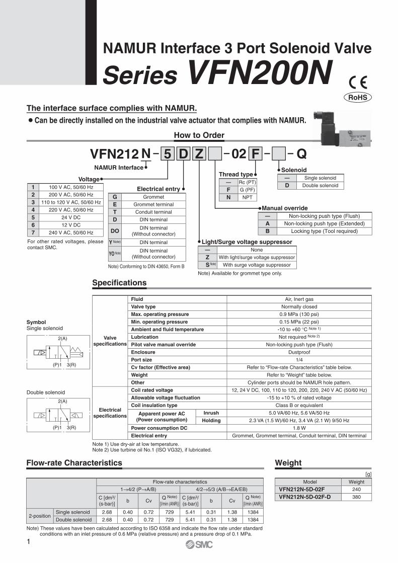
SymbolSingle solenoid
NAMUR Interface 3 Port Solenoid Valve
Series VFN200N
Note 1) Use dry-air at low temperature.Note 2) Use turbine oil No.1 (ISO VG32), if lubricated.
Note) These values have been calculated according to ISO 6358 and indicate the fl ow rate under standard conditions with an inlet pressure of 0.6 MPa (relative pressure) and a pressure drop of 0.1 MPa.
Valve specifi cations
Fluid Air, Inert gas
Valve type Normally closed
Max. operating pressure 0.9 MPa (130 psi)
Min. operating pressure 0.15 MPa (22 psi)
Ambient and fl uid temperature -10 to +60 °C Note 1)
Lubrication Not required Note 2)
Pilot valve manual override Non-locking push type (Flush)
Enclosure Dustproof
Port size 1/4
Cv factor (Effective area) Refer to “Flow-rate Characteristics” table below.
Weight Refer to “Weight” table below.
Other Cylinder ports should be NAMUR hole pattern.
Electrical specifi cations
Coil rated voltage 12, 24 V DC, 100, 110 to 120, 200, 220, 240 V AC (50/60 Hz)
Allowable voltage fl uctuation -15 to +10 % of rated voltage
Coil insulation type Class B or equivalent
Apparent power AC(Power consumption)
Inrush 5.0 VA/60 Hz, 5.6 VA/50 Hz
Holding 2.3 VA (1.5 W)/60 Hz, 3.4 VA (2.1 W) 9/50 Hz
Power consumption DC 1.8 W
Electrical entry Grommet, Grommet terminal, Conduit terminal, DIN terminal
Flow-rate characteristics
1→4/2 (P→A/B) 4/2→5/3 (A/B→EA/EB)
C [dm3/(s·bar)]
b CvQ Note)
[l/min (ANR)]C [dm3/(s·bar)]
b CvQ Note)
[l/min (ANR)]
2-positionSingle solenoid 2.68 0.40 0.72 729 5.41 0.31 1.38 1384
Double solenoid 2.68 0.40 0.72 729 5.41 0.31 1.38 1384
Specifi cations
Flow-rate Characteristics Weight
Model Weight
VFN212N-5D-02F 240
VFN212N-5D-02F-D 380
[g]
NAMUR Interface
Manual override— Non-locking push type (Flush)A Non-locking push type (Extended)B Locking type (Tool required)
Electrical entryG Grommet
E Grommet terminal
T Conduit terminal
D DIN terminal
DO DIN terminal(Without connector)
Y Note) DIN terminal
YO Note) DIN terminal(Without connector)
Note) Conforming to DIN 43650, Form B
Voltage1 100 V AC, 50/60 Hz
2 200 V AC, 50/60 Hz
3 110 to 120 V AC, 50/60 Hz
4 220 V AC, 50/60 Hz
5 24 V DC
6 12 V DC
7 240 V AC, 50/60 Hz
For other rated voltages, please contact SMC.
Light/Surge voltage suppressor— None
Z With light/surge voltage suppressor
S Note) With surge voltage suppressor
Note) Available for grommet type only.
2(A)
(P)1 3(R)
2(A)
(P)1 3(R)
Double solenoid
Thread type— Rc (PT)
F G (PF)
N NPT
Solenoid— Single solenoid
D Double solenoid
VFN212 02N 5 FD Z
How to Order
The interface surface complies with NAMUR.
¡ Can be directly installed on the industrial valve actuator that complies with NAMUR.
RoHS
Q
2
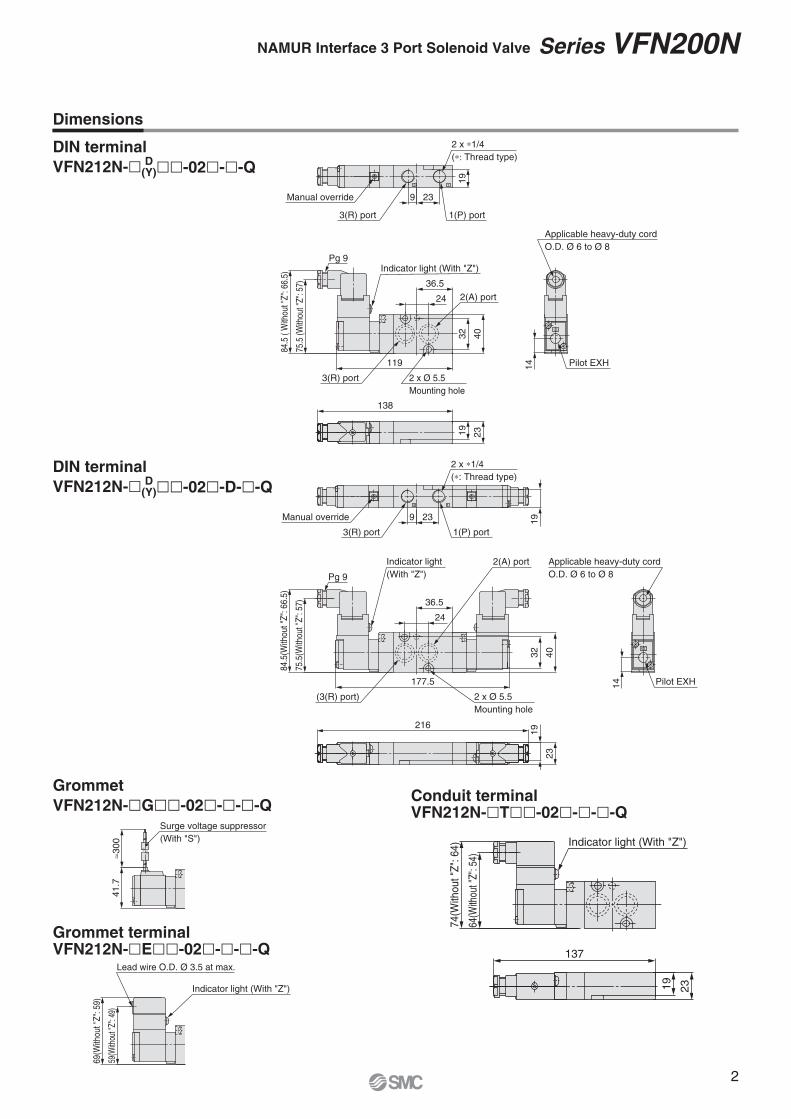
GrommetVFN212N-�G��-02�-�-�-Q
DIN terminalVFN212N-� D
(Y)��-02�-�-Q
DIN terminalVFN212N-� D
(Y)��-02�-D-�-Q
Conduit terminalVFN212N-�T��-02�-�-�-Q
Grommet terminalVFN212N-�E��-02�-�-�-Q
SMC
13
138
Applicable heavy-duty cordO.D. Ø 6 to Ø 8
84.5
( W
ithou
t "Z"
: 66.
5)
75.5
(With
out "
Z": 5
7)
3(R) port 2 x Ø 5.5Mounting hole
119
Pg 9
19 23
36.5
4032
24
2 x ∗1/4(∗: Thread type)
1(P) port3(R) port
Manual override 9 23
19
14 Pilot EXH
Indicator light (With "Z")
2(A) port
SMC
13
216
232(A) portIndicator light
(With "Z")
36.5
24
Pg 9
75.5
(With
out "
Z": 5
7)
84.5
(With
out "
Z": 6
6.5)
(3(R) port)
177.5
2 x Ø 5.5Mounting hole
Applicable heavy-duty cordO.D. Ø 6 to Ø 8
Manual override
3(R) port 1(P) port
239
2 x ∗1/4(∗: Thread type)
32 40
19
14
19
Pilot EXH
Lead wire O.D. Ø 3.5 at max.
Indicator light (With "Z")
69(W
ithou
t "Z"
: 59)
59(W
ithou
t "Z"
: 49)
137
19 23
Indicator light (With "Z")
74(W
ithou
t "Z"
: 64)
64(W
ithou
t "Z"
: 54)
41.7
300
Surge voltage suppressor(With "S")
Dimensions
NAMUR Interface 3 Port Solenoid Valve Series VFN200N
3
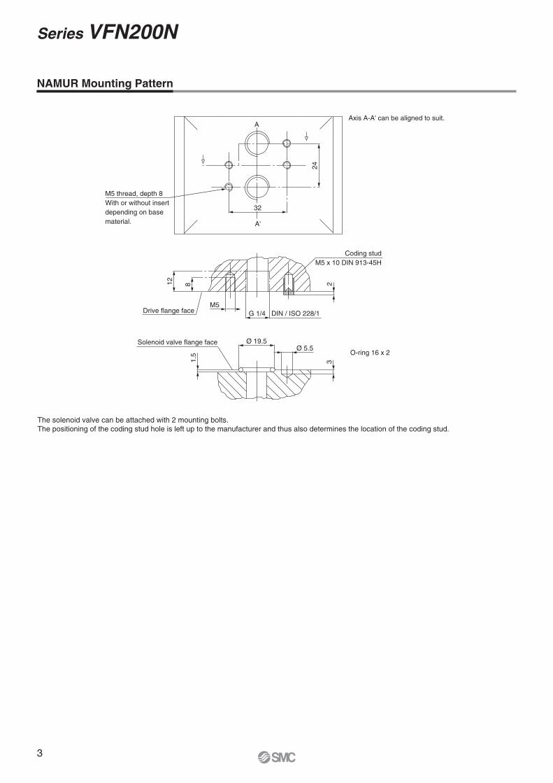
Series VFN200N
A
A'
O-ring 16 x 2
Axis A-A' can be aligned to suit.
2
M5
812
24
Coding studM5 x 10 DIN 913-45H
Drive flange face
M5 thread, depth 8With or without insertdepending on basematerial.
Solenoid valve flange face
G 1/4 DIN / ISO 228/1
3
Ø 19.5Ø 5.5
1.5
32
The solenoid valve can be attached with 2 mounting bolts.The positioning of the coding stud hole is left up to the manufacturer and thus also determines the location of the coding stud.
NAMUR Mounting Pattern
4
2(B)
3(EB)1(P)
(A)4
(EA)5
2(B)
3(EB)1(P)
(A)4
(EA)5
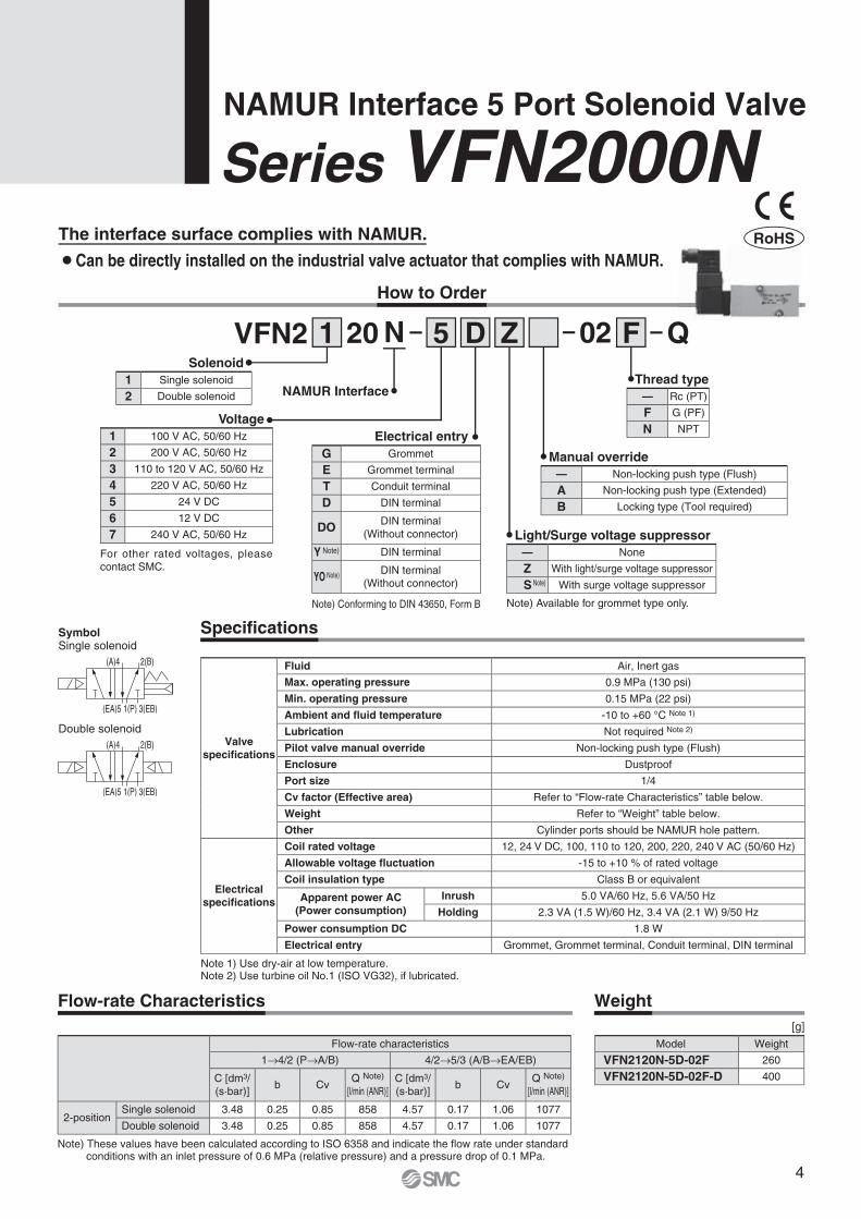
SymbolSingle solenoid
Double solenoid
NAMUR Interface 5 Port Solenoid Valve
Series VFN2000N
Note 1) Use dry-air at low temperature.Note 2) Use turbine oil No.1 (ISO VG32), if lubricated.
Valve specifi cations
Fluid Air, Inert gas
Max. operating pressure 0.9 MPa (130 psi)
Min. operating pressure 0.15 MPa (22 psi)
Ambient and fl uid temperature -10 to +60 °C Note 1)
Lubrication Not required Note 2)
Pilot valve manual override Non-locking push type (Flush)
Enclosure Dustproof
Port size 1/4
Cv factor (Effective area) Refer to “Flow-rate Characteristics” table below.
Weight Refer to “Weight” table below.
Other Cylinder ports should be NAMUR hole pattern.
Electrical specifi cations
Coil rated voltage 12, 24 V DC, 100, 110 to 120, 200, 220, 240 V AC (50/60 Hz)
Allowable voltage fl uctuation -15 to +10 % of rated voltage
Coil insulation type Class B or equivalent
Apparent power AC(Power consumption)
Inrush 5.0 VA/60 Hz, 5.6 VA/50 Hz
Holding 2.3 VA (1.5 W)/60 Hz, 3.4 VA (2.1 W) 9/50 Hz
Power consumption DC 1.8 W
Electrical entry Grommet, Grommet terminal, Conduit terminal, DIN terminal
Specifi cations
Flow-rate Characteristics Weight[g]
NAMUR Interface
Manual override— Non-locking push type (Flush)
A Non-locking push type (Extended)
B Locking type (Tool required)
Electrical entryG Grommet
E Grommet terminal
T Conduit terminal
D DIN terminal
DO DIN terminal(Without connector)
Y Note) DIN terminal
YO Note) DIN terminal(Without connector)
Note) Conforming to DIN 43650, Form B
Voltage1 100 V AC, 50/60 Hz
2 200 V AC, 50/60 Hz
3 110 to 120 V AC, 50/60 Hz
4 220 V AC, 50/60 Hz
5 24 V DC
6 12 V DC
7 240 V AC, 50/60 Hz
For other rated voltages, please contact SMC.
Solenoid1 Single solenoid
2 Double solenoid
Light/Surge voltage suppressor— None
Z With light/surge voltage suppressor
S Note) With surge voltage suppressor
Note) Available for grommet type only.
Thread type— Rc (PT)
F G (PF)
N NPT
VFN2 0220 N1 5 FD Z
The interface surface complies with NAMUR.
¡ Can be directly installed on the industrial valve actuator that complies with NAMUR.
How to Order
Q
RoHS
Flow-rate characteristics
1→4/2 (P→A/B) 4/2→5/3 (A/B→EA/EB)
C [dm3/(s·bar)]
b CvQ Note)
[l/min (ANR)]C [dm3/(s·bar)]
b CvQ Note)
[l/min (ANR)]
2-positionSingle solenoid 3.48 0.25 0.85 858 4.57 0.17 1.06 1077
Double solenoid 3.48 0.25 0.85 858 4.57 0.17 1.06 1077
Model Weight
VFN2120N-5D-02F 260
VFN2120N-5D-02F-D 400
Note) These values have been calculated according to ISO 6358 and indicate the fl ow rate under standard conditions with an inlet pressure of 0.6 MPa (relative pressure) and a pressure drop of 0.1 MPa.
5
Series VFN2000N
300
41.7
Surge voltage suppressor(With "S")
59(W
ithou
t "Z"
: 48.
5)
69(W
ithou
t "Z"
: 58.
5)
Indicator light (With "Z")
Lead wire O.D. Ø 3.5 at max.148
2319
Indicator light(With "Z")
64(W
ithou
t "Z"
: 54)
74(W
ithou
t "Z
": 6
4)
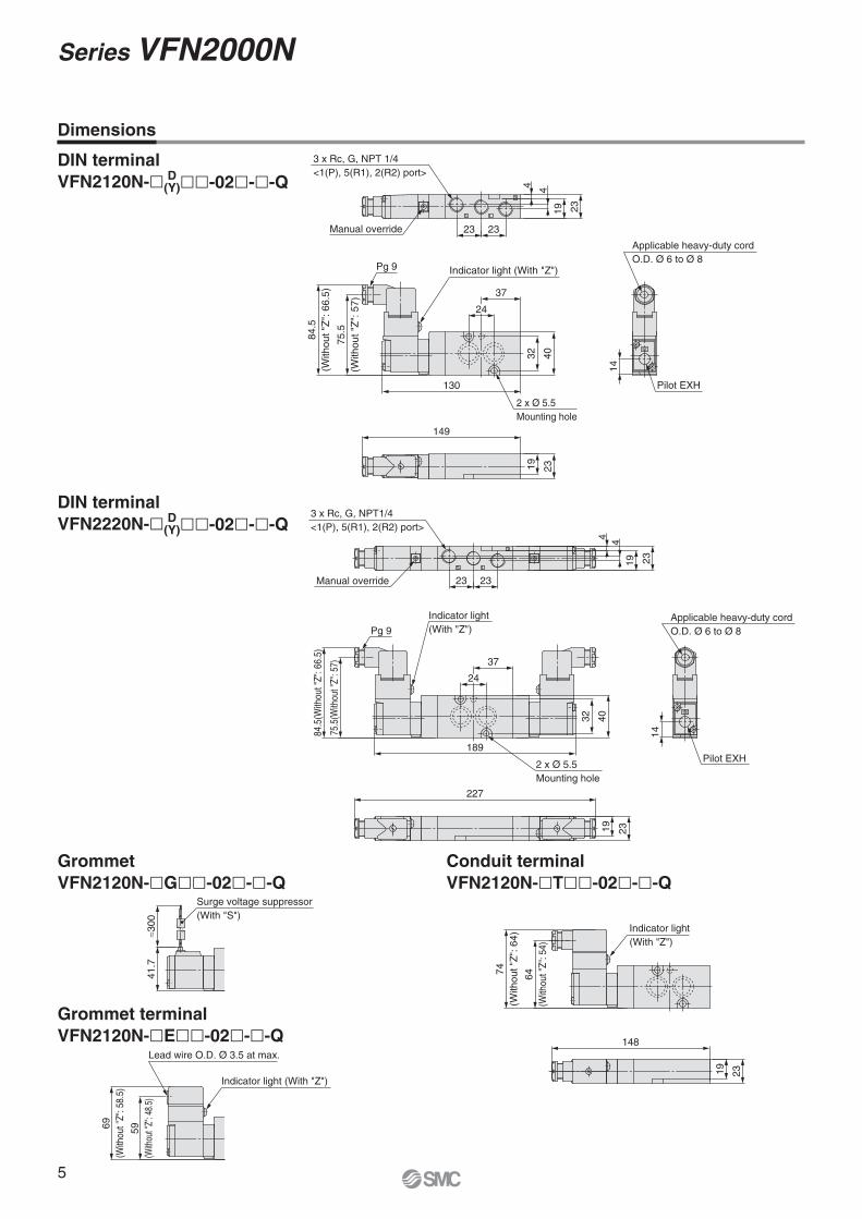
GrommetVFN2120N-�G��-02�-�-Q
Conduit terminalVFN2120N-�T��-02�-�-Q
Grommet terminalVFN2120N-�E��-02�-�-Q
DIN terminalVFN2120N-� D
(Y)��-02�-�-Q
DIN terminalVFN2220N-� D
(Y)��-02�-�-Q
Dimensions
3
5 1
SMC
2323
4032
130
37
84.5
(With
out "
Z":
66.
5)
75.5
( With
out "
Z":
57)
3 x Rc, G, NPT 1/4<1(P), 5(R1), 2(R2) port>
149
Manual override
2 x Ø 5.5Mounting hole
Indicator light (With "Z")
Pilot EXH
Applicable heavy-duty cordO.D. Ø 6 to Ø 8
14
Pg 9
2319
2319
4 4
24
SMC
3
5 1
3 x Rc, G, NPT1/4<1(P), 5(R1), 2(R2) port>
189
23 23
2319
4 4
Manual override
4032
2 x Ø 5.5Mounting hole
Indicator light(With "Z")Pg 9
75.5
(With
out "
Z": 5
7)
84.5
(With
out "
Z": 6
6.5)
37
Applicable heavy-duty cordO.D. Ø 6 to Ø 8
Pilot EXH
14
19 23
227
24
6
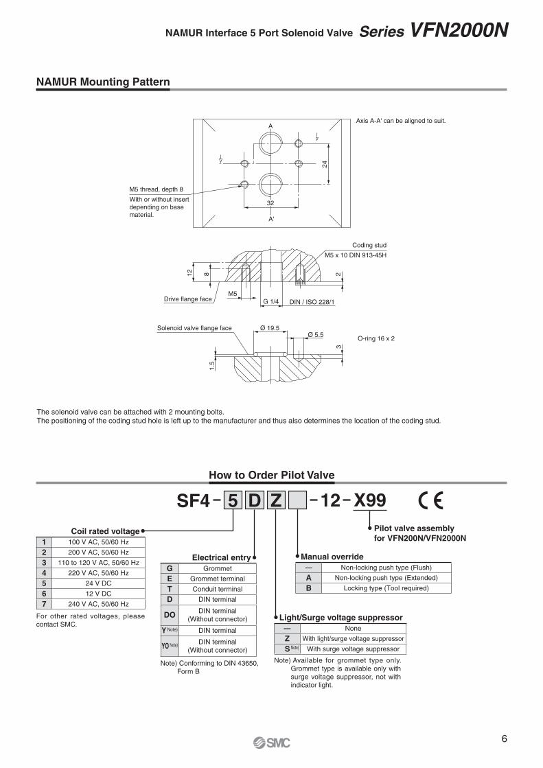
NAMUR Interface 5 Port Solenoid Valve Series VFN2000N
24
A
G 1/4M5
12 8 2
Coding stud
M5 x 10 DIN 913-45H
Drive flange face
Ø 19.5Ø 5.5
1.5
3
Solenoid valve flange face
O-ring 16 x 2
Axis A-A' can be aligned to suit.
M5 thread, depth 8
With or without insertdepending on basematerial.
32
DIN / ISO 228/1
A'
The solenoid valve can be attached with 2 mounting bolts.The positioning of the coding stud hole is left up to the manufacturer and thus also determines the location of the coding stud.
NAMUR Mounting Pattern
Manual override— Non-locking push type (Flush)
A Non-locking push type (Extended)
B Locking type (Tool required)
Electrical entryG Grommet
E Grommet terminal
T Conduit terminal
D DIN terminal
DO DIN terminal(Without connector)
Y Note) DIN terminal
YO Note) DIN terminal(Without connector)
Note) Conforming to DIN 43650, Form B
Coil rated voltage1 100 V AC, 50/60 Hz
2 200 V AC, 50/60 Hz
3 110 to 120 V AC, 50/60 Hz
4 220 V AC, 50/60 Hz
5 24 V DC
6 12 V DC
7 240 V AC, 50/60 Hz
For other rated voltages, please contact SMC.
Light/Surge voltage suppressor— None
Z With light/surge voltage suppressor
S Note) With surge voltage suppressor
Note) Available for grommet type only. Grommet type is available only with surge voltage suppressor, not with indicator light.
How to Order Pilot Valve
Pilot valve assemblyfor VFN200N/VFN2000N
125 D ZSF4 X99
7
NAMUR Interface Solenoid ValvesSpecifi c Product Precautions 1Be sure to read this before handling.
1. Actuator driveWhen an actuator, such as a cylinder, is to be driven using a valve, take appropriate measures to prevent potential danger caused by actuator operation.
2. Holding pressure (including vacuum)Since the valves are subject to air leakage, they cannot be used for applications such as holding pressure (including vac-uum) in a pressure vessel.
3. Not suitable for use as an emergency shutoff valve, etc.The valves are not designed for safety applications such as an emergency shutoff valve. If the valves are used for the men-tioned applications, additional safety measures should be adopted.
4. Ensure sufficient space for maintenance activities.When installing the products, allow access for maintenance.
5. Release of residual pressureFor maintenance purposes install a system for releasing residual pressure.
3. Solenoid valve drive with SSRIf the minimum load current of the SSR is larger than that of the solenoid valve, this may cause a malfunction.When selecting the SSR, refer to the element catalogue specifi cations.
4. Surge voltage suppressorIf a surge protection circuit contains nonstandard diodes, such as Zener diodes or ZNR, a residual voltage that is in propor-tion to the protective circuit and the rated voltage will remain. Therefore, take into consideration the surge voltage protection of the controller.In the case of diodes, the residual voltage is approximately 1 V.
5. Operation in a low temperature conditionIt is possible to operate a valve in extreme temperature, as low as -10 °C. Take appropriate measures to avoid freezing of drainage, moisture etc. in low temperature.
6. Mounting orientationMounting orientation of a single solenoid valve is universal. When installing a double solenoid valve, mount the valve so that spool valve is horizontal.
Design Selection
Warning
1. Confi rm the specifi cations.Products are designed only for use in compressed air systems (including vacuum). Do not operate at pressures or tempera-tures, etc., beyond the range of specifications, as this can cause damage or malfunction. (Refer to the specifications.)Please contact SMC when using a fluid other than com-pressed air (including vacuum).
2. Extended periods of continuous energizationPlease contact SMC when a valve is continuously energised for an extended period of time or when the energised period is longer than the de-energised period.
Selection
Warning
1. Momentary energisation (Double solenoid valve)If a double solenoid valve is operated with momentary ener-gization, it should be energised for at least 0.1 second.However, depending on the condition of the secondary load, itshould be energised until the cylinder reaches the stroke end position, since there is a possibility of malfunction.
Caution
1. If air leakage increases or equipment does not operate properly, stop operation.Check mounting conditions when air and power supplies are connected. Initial function and leakage tests should be per-formed after installation.
2. Operation manualInstall the products and operate them only after reading the operation manual carefully and understanding its contents.Also, keep the manual where it can be referred to as neces-sary.
3. Painting and coatingWarnings or specifications printed or affixed to the product should not be erased, removed or covered up. Also, applying paint to resinous parts may have an adverse effect due to the solvent in the paint.
Mounting
Warning
Caution
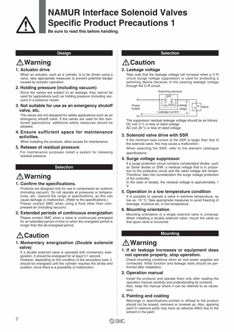
OFF
C RLeakage voltage
Valve
Leakage current
Powersupply
Switching element
The suppressor residual leakage voltage should be as follows.DC coil: 3 % or less of rated voltageAC coil: 20 % or less of rated voltage
2. Leakage voltageTake note that the leakage voltage will increase when a C-R circuit (surge voltage suppressor) is used for protecting a switching device because of the passing leakage voltage through the C-R circuit.
8
NAMUR Interface Solenoid ValvesSpecifi c Product Precautions 2Be sure to read this before handling.
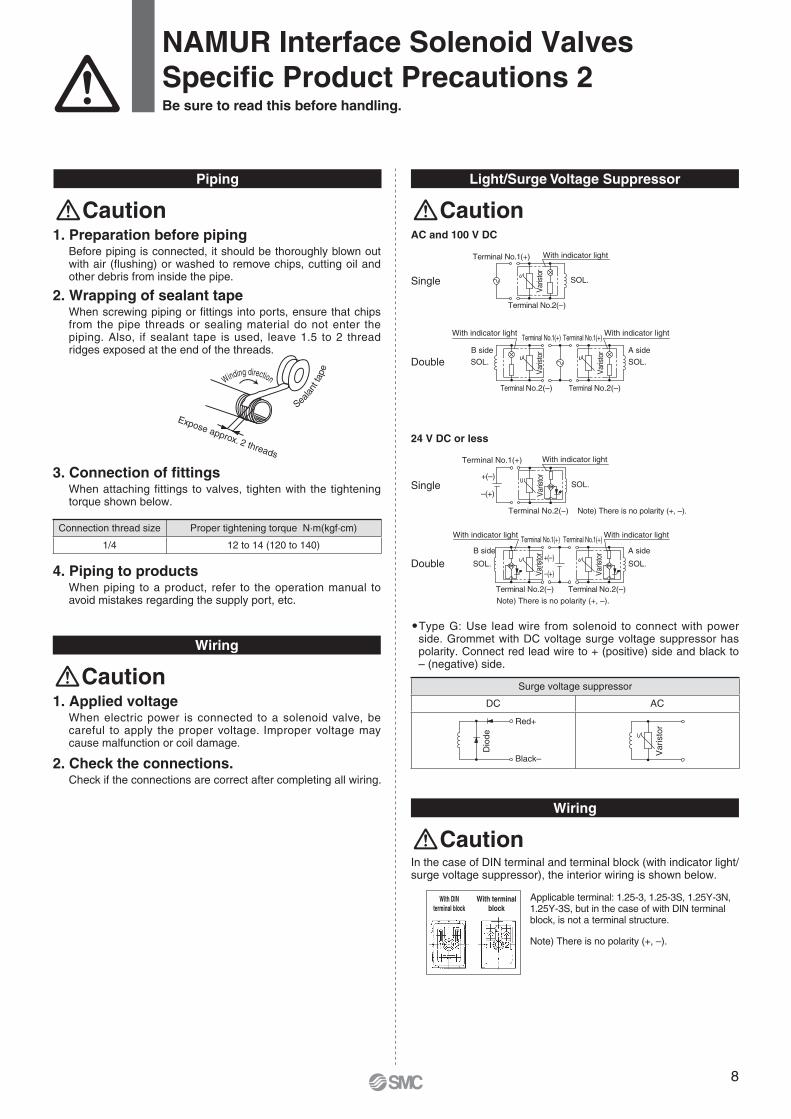
Light/Surge Voltage SuppressorPiping
3. Connection of fi ttingsWhen attaching fittings to valves, tighten with the tightening torque shown below.
4. Piping to productsWhen piping to a product, refer to the operation manual to avoid mistakes regarding the supply port, etc.
1. Preparation before pipingBefore piping is connected, it should be thoroughly blown out with air (flushing) or washed to remove chips, cutting oil and other debris from inside the pipe.
2. Wrapping of sealant tapeWhen screwing piping or fi ttings into ports, ensure that chips from the pipe threads or sealing material do not enter the piping. Also, if sealant tape is used, leave 1.5 to 2 thread ridges exposed at the end of the threads.
Expose approx. 2 threads
Winding direction
Seala
nt ta
pe
SOL.
Varis
tor
With indicator light
Terminal No.2(–)
Terminal No.1(+)
A sideB side
SOL.
Terminal No.2(–)
With indicator lightTerminal No.1(+)
SOL.
Varis
tor
With indicator light
Terminal No.2(–)
Terminal No.1(+)
Varis
tor
–(+)
+(–)
Note) There is no polarity (+, –).
SOL.
Varis
tor
With indicator light
Terminal No.2(−)
Terminal No.1(+)
–(+)
+(–)
Note) There is no polarity (+, –).
A sideB side
SOL.
Terminal No.2(–)
With indicator lightTerminal No.1(+)
SOL.
With indicator light
Terminal No.2(–)
Terminal No.1(+)Va
risto
r
Varis
tor
Black–
Red+
Dio
de
Var
isto
rWiring
1. Applied voltageWhen electric power is connected to a solenoid valve, be careful to apply the proper voltage. Improper voltage may cause malfunction or coil damage.
2. Check the connections.Check if the connections are correct after completing all wiring.
Caution
CautionCaution
Connection thread size Proper tightening torque N·m(kgf·cm)
1/4 12 to 14 (120 to 140)
AC and 100 V DC
24 V DC or less
Single
Single
Double
Double
�Type G: Use lead wire from solenoid to connect with power side. Grommet with DC voltage surge voltage suppressor has polarity. Connect red lead wire to + (positive) side and black to – (negative) side.
Wiring
In the case of DIN terminal and terminal block (with indicator light/surge voltage suppressor), the interior wiring is shown below.
Applicable terminal: 1.25-3, 1.25-3S, 1.25Y-3N, 1.25Y-3S, but in the case of with DIN terminal block, is not a terminal structure.
Note) There is no polarity (+, –).
With DINterminal block
With terminalblock
Surge voltage suppressor
DC AC
Caution
9
Lubrication
1. Lubrication1) The valve has been lubricated for life at the factory, and
does not require any further lubrication.2) If a lubricant is used in the system, use class 1 turbine oil
(no additive), ISO VG32. Once a lubricant is used in the system, lubrication must be continued because the original lubricant applied during manufacturing will be washed away. Refer to each manufacturer's brand name of class 1 turbine oil (no additive), ISO VG32 as shown below.
Class 1 Turbine Oil (No additive), ISO VG32
NAMUR Interface Solenoid ValvesSpecifi c Product Precautions 3Be sure to read this before handling.
Air SupplyChanging Direction of DIN Terminal/Cable Entry
2. Take measures to ensure air quality, such as by installing an aftercooler, air dryer, or water separator.Compressed air that contains a large amount of drainage can cause malfunction of pneumatic equipment such as valves. Therefore, take appropriate measures to ensure air quality, such as by providing an aftercooler, air dryer, or water separa-tor.
3. If excessive carbon powder is seen, install a mist separator on the upstream side of the valve.If excessive carbon dust is generated by the compressor, it may adhere to the inside of a valve and cause it to malfunction.
For compressed air quality, refer to SMC Best Pneumatics catalogue.
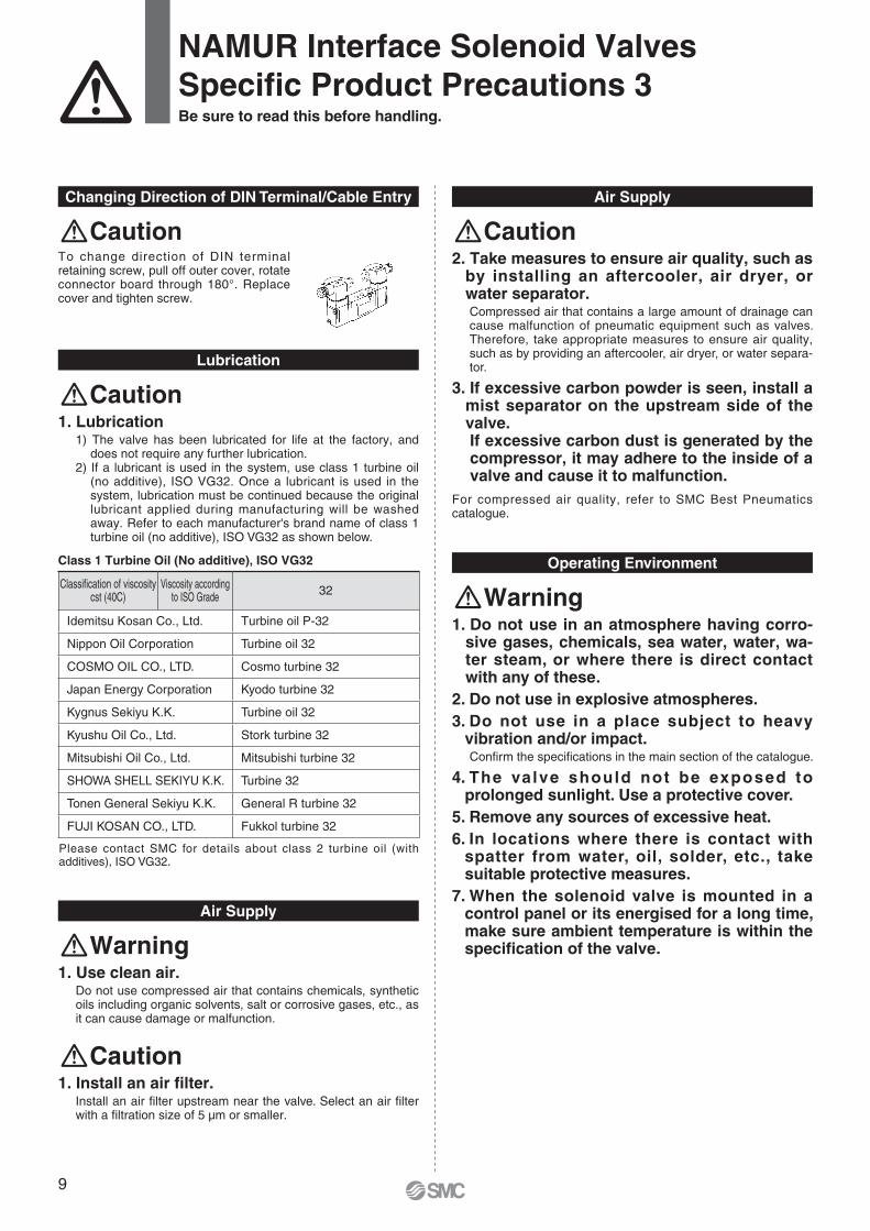
To change direction of DIN terminal retaining screw, pull off outer cover, rotate connector board through 180°. Replace cover and tighten screw.
Caution
Please contact SMC for details about class 2 turbine oil (with additives), ISO VG32.
Classifi cation of viscositycst (40C)
Viscosity according to ISO Grade 32
Idemitsu Kosan Co., Ltd. Turbine oil P-32
Nippon Oil Corporation Turbine oil 32
COSMO OIL CO., LTD. Cosmo turbine 32
Japan Energy Corporation Kyodo turbine 32
Kygnus Sekiyu K.K. Turbine oil 32
Kyushu Oil Co., Ltd. Stork turbine 32
Mitsubishi Oil Co., Ltd. Mitsubishi turbine 32
SHOWA SHELL SEKIYU K.K. Turbine 32
Tonen General Sekiyu K.K. General R turbine 32
FUJI KOSAN CO., LTD. Fukkol turbine 32
CautionCaution
Operating Environment
1. Do not use in an atmosphere having corro-sive gases, chemicals, sea water, water, wa-ter steam, or where there is direct contact with any of these.
2. Do not use in explosive atmospheres.3. Do not use in a place subject to heavy
vibration and/or impact.Confi rm the specifi cations in the main section of the catalogue.
4. The valve should not be exposed to prolonged sunlight. Use a protective cover.
5. Remove any sources of excessive heat.6. In locations where there is contact with
spatter from water, oil, solder, etc., take suitable protective measures.
7. When the solenoid valve is mounted in a control panel or its energised for a long time, make sure ambient temperature is within the specifi cation of the valve.
Warning
Air Supply
1. Use clean air.Do not use compressed air that contains chemicals, synthetic oils including organic solvents, salt or corrosive gases, etc., as it can cause damage or malfunction.
Warning
1. Install an air fi lter.Install an air fi lter upstream near the valve. Select an air fi lter with a fi ltration size of 5 µm or smaller.
Caution
10
NAMUR Interface Solenoid ValvesSpecifi c Product Precautions 4Be sure to read this before handling.
1. Perform maintenance inspection according to the procedures indicated in the operation manual.If handled improperly, malfunction and damage of machinery or equipment may occur.
2. Removal of equipment, and supply/exhaust of compressed airWhen components are removed, first confirm that measures are in place to prevent workpieces from dropping, run-away equipment, etc. Then, cut off the supply pressure and electric power, and exhaust all compressed air from the system using the residual pressure release function. For 3-position closed centre type, exhaust the residual pressure between the valve and the cylinder.When the equipment is operated after remounting or replace-ment, first confirm that measures are in place to prevent lurch-ing of actuators, etc. Then, confirm that the equipment is oper-ating normally.
3. Low frequency operationValves should be operated at least once every 30 days to pre-vent malfunction. (Use caution regarding the air supply.)
4. Manual overrideWhen the manual override is operated, connected equipment will be actuated. Operate after safety is confirmed.
Maintenance
Warning
1. Drain flushingRemove drainage from the air filters regularly.
2. LubricationOnce lubrication has been started, it must be continued.Use class 1 turbine oil (with no additive), VG32. If other lubricant oil is used, it may cause malfunction. Please contact SMC for suggested class 2 turbine oil (with additive), VG32.
Caution
11
How to Order
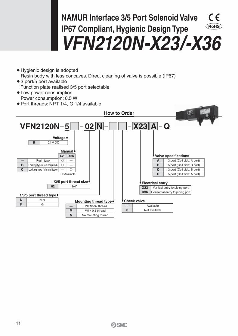
Voltage5 24 V DC
Valve specificationsA 3 port (Coil side: A port)
B 5 port (Coil side: B port)
C 3 port (Coil side: B port)
D 5 port (Coil side: A port)
Electrical entryX23 Vertical entry to piping port
X36 Horizontal entry to piping port
ManualX23 X36
— Push type � —
B Locking type (Tool required) � —
C Locking type (Manual type) — �
�: Available
1/3/5 port thread size02 1/4"
1/3/5 port thread typeN NPT
F GMounting thread type
— UNF10-32 thread
M M5 x 0.8 thread
N No mounting thread
Check valve— Available
0 Not available
NAMUR Interface 3/5 Port Solenoid ValveIP67 Compliant, Hygienic Design Type
VFN2120N-X23/-X36
VFN2120N 02 X23N A Q5
¡ Hygienic design is adoptedResin body with less concaves. Direct cleaning of valve is possible (IP67)
¡ 3 port/5 port availableFunction plate realised 3/5 port selectable
¡ Low power consumptionPower consumption: 0.5 W
¡ Port threads: NPT 1/4, G 1/4 available
RoHS
12
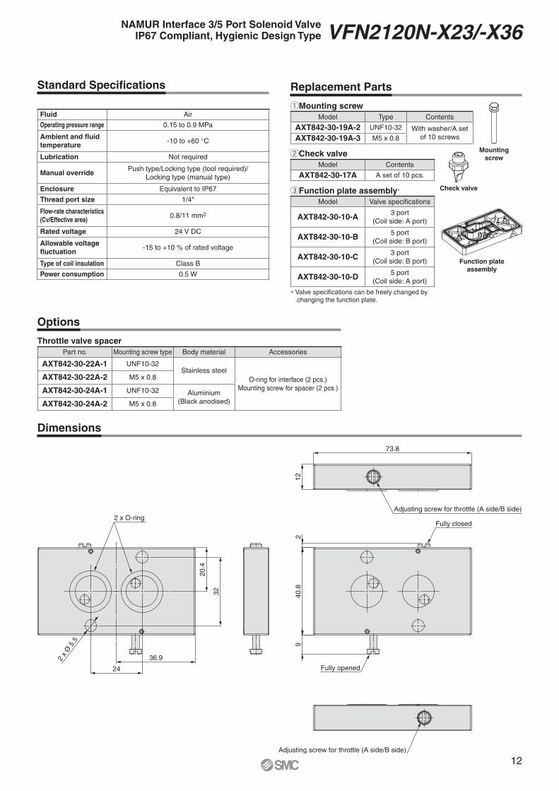
eFunction plate assembly∗
Model Valve specifi cations
AXT842-30-10-A 3 port(Coil side: A port)
AXT842-30-10-B 5 port (Coil side: B port)
AXT842-30-10-C 3 port (Coil side: B port)
AXT842-30-10-D 5 port (Coil side: A port)
∗ Valve specifi cations can be freely changed by changing the function plate.
qMounting screwModel Type Contents
AXT842-30-19A-2 UNF10-32 With washer/A set of 10 screwsAXT842-30-19A-3 M5 x 0.8
wCheck valveModel Contents
AXT842-30-17A A set of 10 pcs.
Fluid Air
Operating pressure range 0.15 to 0.9 MPa
Ambient and fl uid temperature
-10 to +60 °C
Lubrication Not required
Manual overridePush type/Locking type (tool required)/
Locking type (manual type)
Enclosure Equivalent to IP67
Thread port size 1/4"
Flow-rate characteristics(Cv/Effective area)
0.8/11 mm2
Rated voltage 24 V DC
Allowable voltage fl uctuation
-15 to +10 % of rated voltage
Type of coil insulation Class B
Power consumption 0.5 W
Standard Specifi cations Replacement Parts
Mounting screw
Check valve
Function plate assembly
Options
Throttle valve spacerPart no. Mounting screw type Body material Accessories
AXT842-30-22A-1 UNF10-32Stainless steel
O-ring for interface (2 pcs.)Mounting screw for spacer (2 pcs.)
AXT842-30-22A-2 M5 x 0.8
AXT842-30-24A-1 UNF10-32 Aluminium(Black anodised)AXT842-30-24A-2 M5 x 0.8
40.8
9
Adjusting screw for throttle (A side/B side)
Fully closed
Fully opened
12
73.8
Adjusting screw for throttle (A side/B side)
24
32
20.4
2 x O-ring
36.92 x
Ø 5
.5
2
Dimensions
NAMUR Interface 3/5 Port Solenoid ValveIP67 Compliant, Hygienic Design Type VFN2120N-X23/-X36
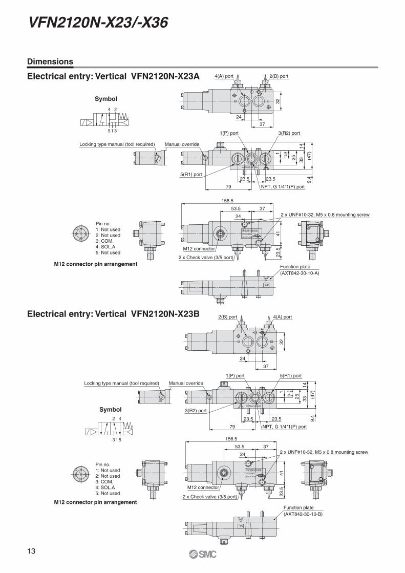
13
VFN2120N-X23/-X36
Symbol
24
315
3/2
5
3
2
1
45
24
1 3
VFN2120N-5-02N-X23A
MADE IN JAPAN
0.15 to 0.9MPa
10
AXT842-30-10A
24
M12 connector pin arrangement
Pin no.1: Not used2: Not used3: COM.4: SOL.A5: Not used
37
24
2(B) port
32
79
Manual override
5(R1) port
156.5
53.5 37
24 2 x UNF#10-32, M5 x 0.8 mounting screw
4123
.5
2 x Check valve (3/5 port)
M12 connector
23.5 23.5
NPT, G 1/4"1(P) port
Locking type manual (tool required)
4(A) port
1(P) port 3(R2) port
(47)
9.4
3314
25
1
14.5
Function plate(AXT842-30-10-A)
Symbol42
513
5
3
2
1
43
42
1 5
VFN2120N-5-02N-X23B
MADE IN JAPAN
0.15 to 0.9MPa
42
10
AXT842-30-10B
5/2
Locking type manual (tool required)
37
32
24
2(B) port 4(A) port
79 NPT, G 1/4"1(P) port
Manual override
23.5 23.5
3(R2) port
1(P) port 5(R1) port
(47)
14332514
.51
9.4
23.5
41
M12 connector
2 x Check valve (3/5 port)
156.5
53.5 37
24 2 x UNF#10-32, M5 x 0.8 mounting screw
M12 connector pin arrangement
Pin no.1: Not used2: Not used3: COM.4: SOL.A5: Not used
Function plate(AXT842-30-10-B)
Dimensions
Electrical entry: Vertical VFN2120N-X23A
Electrical entry: Vertical VFN2120N-X23B
14
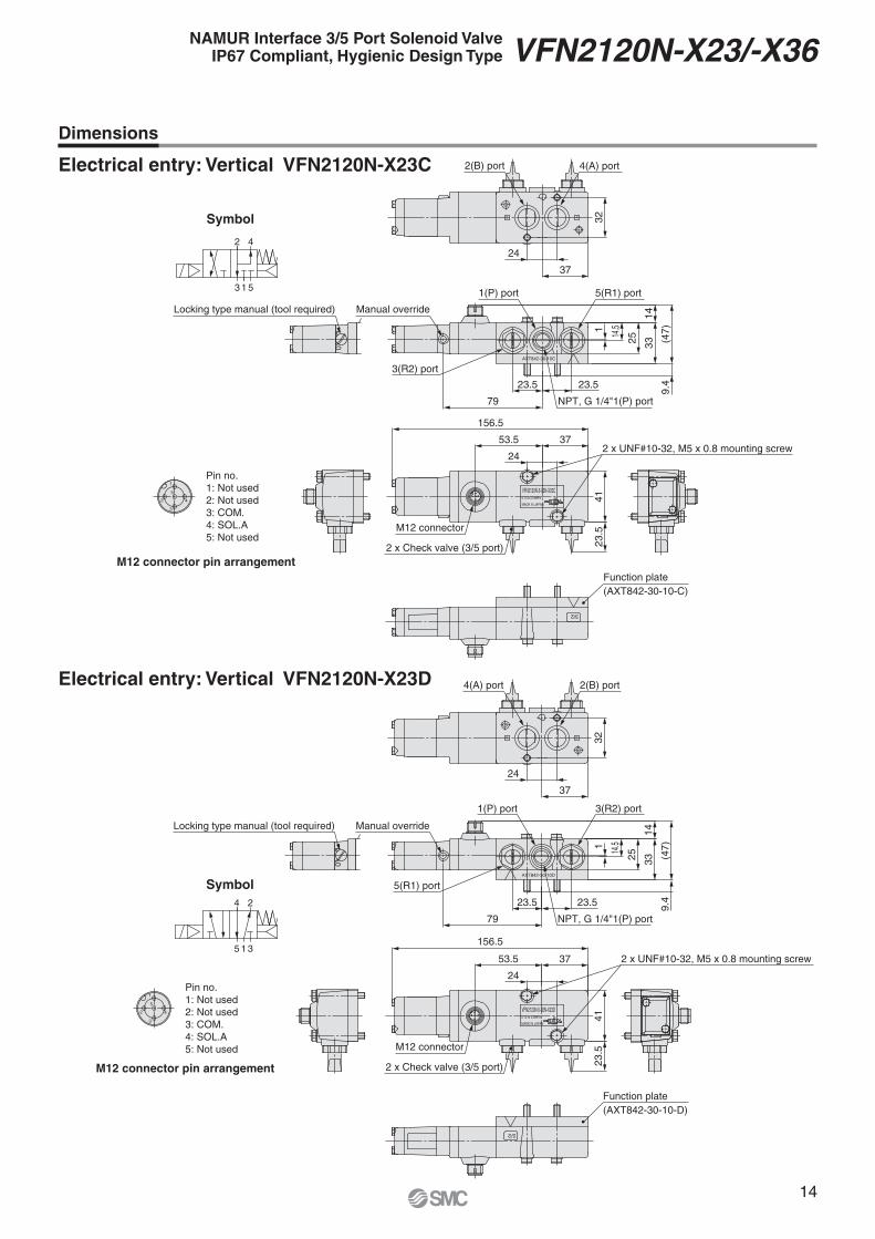
NAMUR Interface 3/5 Port Solenoid ValveIP67 Compliant, Hygienic Design Type VFN2120N-X23/-X36
Symbol
42
513
3/2
5
3
2
1
43
42
1 5
VFN2120N-5-02N-X23C
MADE IN JAPAN
0.15 to 0.9MPa
AXT842-30-10C
10
42
Locking type manual (tool required)
2(B) port 4(A) port
32
37
79 NPT, G 1/4"1(P) port
23.5 23.5
3(R2) port
Manual override
1(P) port 5(R1) port
(47)
3325
14.5
14
9.4
1
2 x UNF#10-32, M5 x 0.8 mounting screw
156.5
M12 connector
2 x Check valve (3/5 port)
4123
.5
53.5 37
M12 connector pin arrangement
Pin no.1: Not used2: Not used3: COM.4: SOL.A5: Not used
24
24
Function plate(AXT842-30-10-C)
Symbol
35 1
4 2
5
3
2
1
4
5
24
1 3
VFN2120N-5-02N-X23D
MADE IN JAPAN
0.15 to 0.9MPa
24
10
AXT842-30-10D
5/2
Locking type manual (tool required)
4(A) port 2(B) port
32
37
Manual override
79 NPT, G 1/4"1(P) port
5(R1) port
23.5 23.5
1(P) port 3(R2) port
(47)
9.4
3325
14.51
14
156.5
53.5 37
4123
.5M12 connector
2 x Check valve (3/5 port)
2 x UNF#10-32, M5 x 0.8 mounting screw
M12 connector pin arrangement
Pin no.1: Not used2: Not used3: COM.4: SOL.A5: Not used
24
24
Function plate(AXT842-30-10-D)
Dimensions
Electrical entry: Vertical VFN2120N-X23C
Electrical entry: Vertical VFN2120N-X23D
15
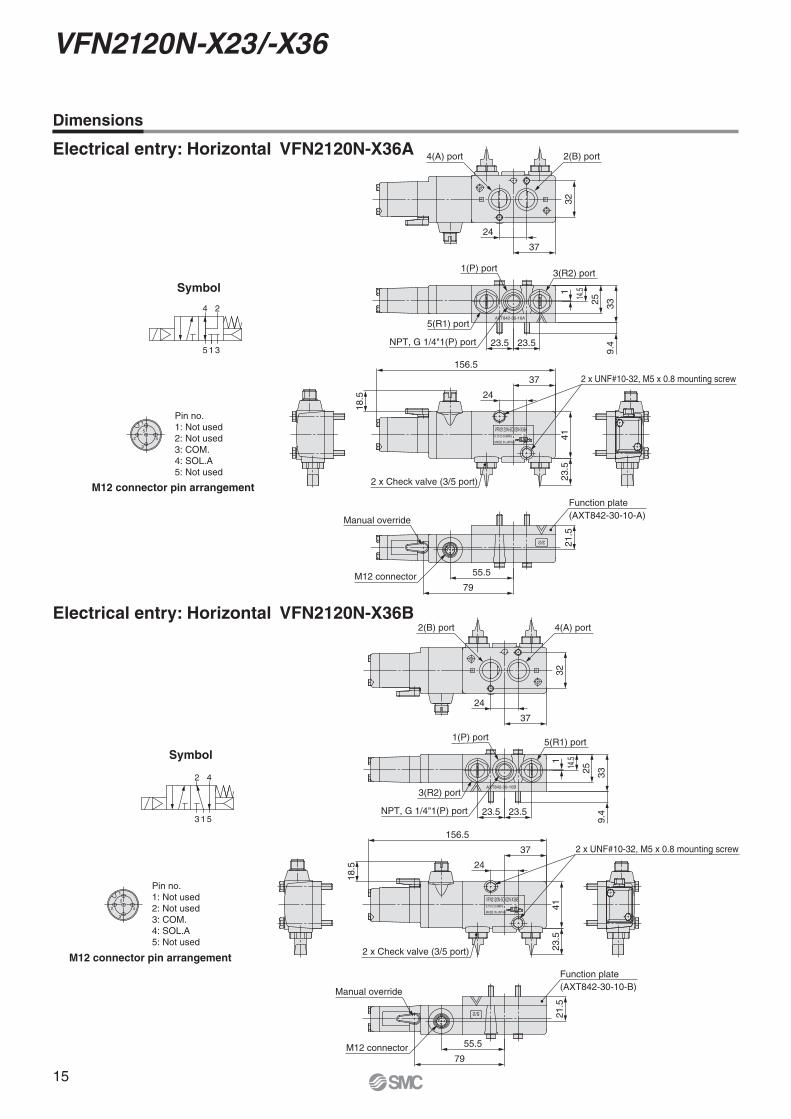
VFN2120N-X23/-X36
Symbol
24
315
5
3
2
1
4
3/2
5
24
1 3
VFN2120N-5C-02N-X36A
MADE IN JAPAN
0.15 to 0.9MPa
AXT842-30-10A
24
M12 connector21
.555.5
79
Manual override
18.5
2 x UNF#10-32, M5 x 0.8 mounting screw
156.5
37
24
4123
.5
2 x Check valve (3/5 port)
1(P) port 3(R2) port
5(R1) port
3325
1 14.5
23.5 23.5
9.4NPT, G 1/4"1(P) port
2(B) port4(A) port
37
32
M12 connector pin arrangement
Pin no.1: Not used2: Not used3: COM.4: SOL.A5: Not used
24
Function plate(AXT842-30-10-A)
Symbol
42
513
5
3
2
1
4
5/2
3
42
1 5
VFN2120N-5C-02N-X36B
MADE IN JAPAN
0.15 to 0.9MPa
AXT842-30-10B
42
Manual override
M12 connector79
55.5
156.5
18.5
37
4123
.5
2 x Check valve (3/5 port)
2 x UNF#10-32, M5 x 0.8 mounting screw
21.5
339.
4
25
1
23.523.5
3(R2) port
NPT, G 1/4"1(P) port
1(P) port 5(R1) port
14.5
4(A) port2(B) port
32
37
M12 connector pin arrangement
Pin no.1: Not used2: Not used3: COM.4: SOL.A5: Not used
24
24
Function plate(AXT842-30-10-B)
Dimensions
Electrical entry: Horizontal VFN2120N-X36A
Electrical entry: Horizontal VFN2120N-X36B
16
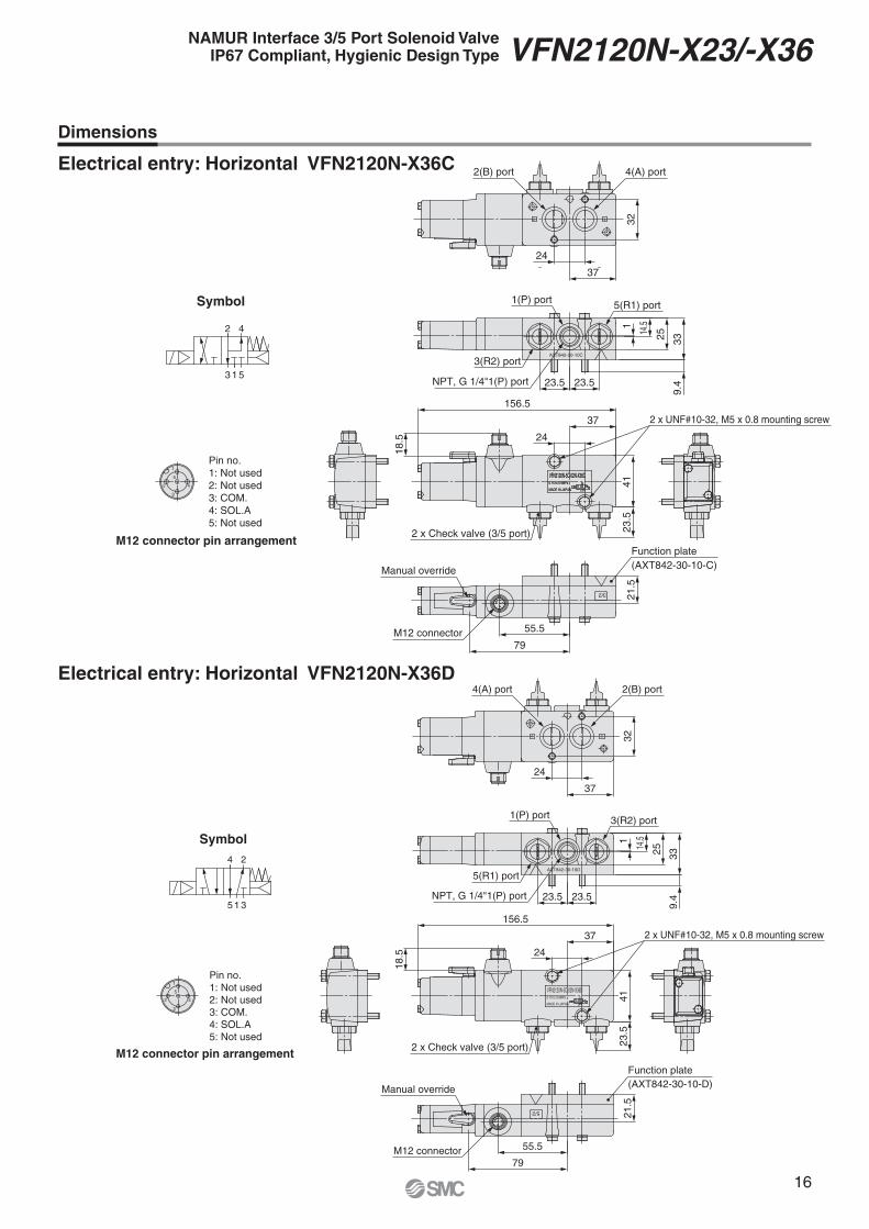
NAMUR Interface 3/5 Port Solenoid ValveIP67 Compliant, Hygienic Design Type VFN2120N-X23/-X36
Symbol
42
513
3
42
1 5
VFN2120N-5C-02N-X36C
MADE IN JAPAN
0.15 to 0.9MPa
5
3
2
1
4
3/2
3
42
1 5
VFN2120N-5C-02N-X36C
MADE IN JAPAN
AXT842-30-10C
42
0.15 to 0.9MPa
M12 connector21
.555.5
79
Manual override
18.5
2 x UNF#10-32, M5 x 0.8 mounting screw
2 x Check valve (3/5 port)
4123
.5
156.5
37
1(P) port 5(R1) port
3(R2) port
NPT, G 1/4"1(P) port 23.523.5
4(A) port2(B) port
32
37
339.
4
2514.51
M12 connector pin arrangement
Pin no.1: Not used2: Not used3: COM.4: SOL.A5: Not used
24
24
Function plate(AXT842-30-10-C)
Symbol
35 1
4 2
M12 connector pin arrangement
Pin no.1: Not used2: Not used3: COM.4: SOL.A5: Not used
5
3
2
1
4
5/2
5
24
1 3
VFN2120N-5C-02N-X36D
MADE IN JAPAN
0.15 to 0.9MPa
AXT842-30-10D
24
M12 connector
21.5
55.5
79
Manual override
18.5
2 x UNF#10-32, M5 x 0.8 mounting screw
2 x Check valve (3/5 port)
4123
.5
156.5
37
1(P) port
NPT, G 1/4"1(P) port 23.523.5
32
37
339.
4
2514.51
3(R2) port
5(R1) port
2(B) port4(A) port
24
24
Function plate(AXT842-30-10-D)
Dimensions
Electrical entry: Horizontal VFN2120N-X36C
Electrical entry: Horizontal VFN2120N-X36D

17

Lithuania +370 5 2308118 www.smclt.lt [email protected] +31 (0)205318888 www.smcpneumatics.nl [email protected] +47 67129020 www.smc-norge.no [email protected] +48 222119600 www.smc.pl [email protected] +351 226166570 www.smc.eu [email protected] +40 213205111 www.smcromania.ro [email protected] +7 8127185445 www.smc-pneumatik.ru [email protected] +421 (0)413213212 www.smc.sk [email protected] +386 (0)73885412 www.smc.si [email protected] +34 902184100 www.smc.eu [email protected] +46 (0)86031200 www.smc.nu [email protected] +41 (0)523963131 www.smc.ch [email protected] +90 212 489 0 440 www.smcpnomatik.com.tr [email protected] UK +44 (0)845 121 5122 www.smcpneumatics.co.uk [email protected]
Specifications are subject to change without prior notice and any obligation on the part of the manufacturer.SMC CORPORATION Akihabara UDX 15F, 4-14-1, Sotokanda, Chiyoda-ku, Tokyo 101-0021, JAPAN Phone: 03-5207-8249 FAX: 03-5298-5362
1st printing VO printing VO 00 Printed in Spain
Austria +43 (0)2262622800 www.smc.at [email protected] +32 (0)33551464 www.smcpneumatics.be [email protected] +359 (0)2807670 www.smc.bg [email protected] Croatia +385 (0)13707288 www.smc.hr [email protected] Republic +420 541424611 www.smc.cz [email protected] Denmark +45 70252900 www.smcdk.com [email protected] Estonia +372 6510370 www.smcpneumatics.ee [email protected] +358 207513513 www.smc.fi [email protected] +33 (0)164761000 www.smc-france.fr [email protected] +49 (0)61034020 www.smc.de [email protected] +30 210 2717265 www.smchellas.gr [email protected] +36 23511390 www.smc.hu [email protected] +353 (0)14039000 www.smcpneumatics.ie [email protected] +39 0292711 www.smcitalia.it [email protected] +371 67817700 www.smclv.lv [email protected]
Safety Instructions Be sure to read “Handling Precautions for SMC Products” (M-E03-3) before using.
SMC Corporation (Europe)
1. The compatibility of the product is the responsibility of the person who designs the equipment or decides its specifications.
Since the product specified here is used under various operating conditions, its compatibility with specific equipment must be decided by the person who designs the equipment or decides its specifications based on necessary analysis and test results. The expected performance and safety assurance of the equipment will be the responsibility of the person who has determined its compatibility with the product. This person should also continuously review all specifications of the product referring to its latest catalogue information, with a view to giving due consideration to any possibility of equipment failure when configuring the equipment.
2. Only personnel with appropriate training should operate machinery and equipment.
The product specified here may become unsafe if handled incorrectly. The assembly, operation and maintenance of machines or equipment including our products must be performed by an operator who is appropriately trained and experienced.
3. . Do not service or attempt to remove product and machinery/equipment until safety is confirmed.1. The inspection and maintenance of machinery/equipment should only be performed
after measures to prevent falling or runaway of the driven objects have been confirmed.
2. When the product is to be removed, confirm that the safety measures as mentioned above are implemented and the power from any appropriate source is cut, and read and understand the specific product precautions of all relevant products carefully.
3. Before machinery/equipment is restarted, take measures to prevent unexpected operation and malfunction.
4. Contact SMC beforehand and take special consideration of safety measures if the product is to be used in any of the following conditions. 1. Conditions and environments outside of the given specifications, or use outdoors or in
a place exposed to direct sunlight.2. Installation on equipment in conjunction with atomic energy, railways, air navigation,
space, shipping, vehicles, military, medical treatment, combustion and recreation, or equipment in contact with food and beverages, emergency stop circuits, clutch and brake circuits in press applications, safety equipment or other applications unsuitable for the standard specifications described in the product catalogue.
3. An application which could have negative effects on people, property, or animals requiring special safety analysis.
4. Use in an interlock circuit, which requires the provision of double interlock for possible failure by using a mechanical protective function, and periodical checks to confirm proper operation.
Warning Limited warranty and Disclaimer/Compliance Requirements The product used is subject to the following “Limited warranty and Disclaimer” and “Compliance Requirements”.Read and accept them before using the product.
1. The product is provided for use in manufacturing industries.The product herein described is basically provided for peaceful use in manufacturing industries. If considering using the product in other industries, consult SMC beforehand and exchange specifications or a contract if necessary. If anything is unclear, contact your nearest sales branch.
CautionSMC products are not intended for use as instruments for legal metrology.Measurement instruments that SMC manufactures or sells have not been qualified by type approval tests relevant to the metrology (measurement) laws of each country.Therefore, SMC products cannot be used for business or certification ordained by the metrology (measurement) laws of each country.
Caution
Limited warranty and Disclaimer1. The warranty period of the product is 1 year in service or 1.5 years
after the product is delivered, wichever is first.∗2)
Also, the product may have specified durability, running distance or replacement parts. Please consult your nearest sales branch.
2. For any failure or damage reported within the warranty period which is clearly our responsibility, a replacement product or necessary parts will be provided. This limited warranty applies only to our product independently, and not to any other damage incurred due to the failure of the product.
3. Prior to using SMC products, please read and understand the warranty terms and disclaimers noted in the specified catalogue for the particular products.
∗2) Vacuum pads are excluded from this 1 year warranty.A vacuum pad is a consumable part, so it is warranted for a year after it is delivered. Also, even within the warranty period, the wear of a product due to the use of the vacuum pad or failure due to the deterioration of rubber material are not covered by the limited warranty.
Compliance Requirements1. The use of SMC products with production equipment for the manufacture of
weapons of mass destruction (WMD) or any other weapon is strictly prohibited.
2. The exports of SMC products or technology from one country to another are governed by the relevant security laws and regulations of the countries involved in the transaction. Prior to the shipment of a SMC product to another country, assure that all local rules governing that export are known and followed.
These safety instructions are intended to prevent hazardous situations and/or equipment damage. These instructions indicate the level of potential hazard with the labels of “Caution,” “Warning” or “Danger.” They are all important notes for safety and must be followed in addition to International Standards (ISO/IEC)∗1), and other safety regulations.
∗1) ISO 4414: Pneumatic fluid power – General rules relating to systems. ISO 4413: Hydraulic fluid power – General rules relating to systems. IEC 60204-1: Safety of machinery – Electrical equipment of machines. (Part 1: General requirements) ISO 10218-1: Manipulating industrial robots - Safety. etc.
Caution indicates a hazard with a low level of risk which, if not avoided, could result in minor or moderate injury.
Warning indicates a hazard with a medium level of risk which, if not avoided, could result in death or serious injury.
Caution:
Warning:
Danger : Danger indicates a hazard with a high level of risk which, if not avoided, will result in death or serious injury.
Safety Instructions