SmartMediaPro (SSP-1200E) S Quick Reference Guidedealers.savantav.com/portal/SavantSandbox/Released...
2
SmartMediaPro (SSP-1200E) Quick Reference Guide 009-0435-02 SSP-1200E-10 Copyright2012 Savant Systems LLC, SAVANT and RacePoint Blueprint are trademarks of Savant Systems, LLC. All brand names, product names and trademarks are the property of their respective owners. Savant Systems, LLC reserves the right to change product specifications without notice. Savant Confidential and Proprietary 050412 45 Perseverance Way, Hyannis, MA 02601 Phone 508.683.2500 Fax 508.683.2600 SavantSystems.com The Savant SmartMediaPro Quick Reference Guide provides information necessary to install an SSP-2400E or SSP-3600E Smart System. The SSP-2400E consists of two SSP-1200Es and the SSP-3600E consists of three SSP-1200Es. The SSP-1200E chassis is not available as a stand-alone product. The SSP-2400E and SSP-3600E are part of Savant’s family of modular matrix switches and controllers. To expand a SmartMediaPro system, two SSP-1200Es can be interconnected to configure an SSP-2400E, and three SSP-1200Es can be interconnected to configure an SSP-3600E. The SmartMediaPro can be field upgraded by adding audio or video processing modules, or audio and video input and output modules based on the needs and complexity of your installation. Important: To confirm this document is the latest version, refer to SavantSystems.com > Dealer Login > Knowledge Base > Products. Box Contents SSP-1200E (Not available as a stand-alone product) (1) SmartMediaPro (SSP-1200E-xx) (1) Installation Kit (075-0116-xx) • (2) 9 pin Screw-Down Plug-In Connector (028-9353-xx) • (2) 6 pin Screw-Down Plug-In Connector (028-9352-xx) • (6) M5 x 8mm Flat Phillips Screw (039-0180-xx) • (1) Ferrite (045-0037-xx) • (1) Power cord C13, 6 feet (N. America) (064-0079-xx) or appropriate international power cord • (1) Mini Display Port to HDMI Cable, 1 meter (064-0222-xx) • (2) Module Removal Tool 12 (071-0268-xx) • (2) Rack Mounting Bracket (6U) (071-0192-xx) • (1) HDMI Locking Cable, 3 feet (CBL-3LHDMI-xx) (1) Quick Reference Guide (this document) SSP-2400E Configuration (2) SmartMediaPro (SSP-1200E-xx) and two Installation Kits(075-0116-xx) – See above Switch Card Cables (2) Expansion Cable (1 meter) (064-0070-xx) (1) S/PDIF Cable (1 meter) (064-0084-xx) Note: There will be one extra Mini Display Port to HDMI and HDMI Locking Cable. SSP-3600E Configuration (3) SmartMediaPro (SSP-1200E-xx) and three Installation Kits (075-0116-xx)– See above Switch Card Cables (6) Expansion Cable (1 meter) (064-0070-xx) (3) S/PDIF Cable (1 meter) (064-0084-xx) Note: There will be two extra Mini Display Port to HDMI and HDMI Locking Cables. Front Panel 1 Standby Power button Press the button for about five seconds to place the system in standby mode. Press the button again for about five seconds to take the system out of standby mode. To turn the power off for the entire system, use the switch on the rear panel. 2 Power LED Green indicates the system has adequate power and is operating normally. Red indicates the system is in standby mode. The controller hardware has power, but the embedded processor is shut off and in the standby mode. Off indicates that the system is not receiving power. 3 Status LED Green indicates the host has evaluated the firmware currently running and determined it is up to date. Green flashing indicates the embedded system is ready (running with DHCP IP address), but the embedded processor has not established communications with the embedded system. Off indicates the embedded processor is resetting or is powered up and is booting the embedded firmware. Red indicates the host has determined the firmware needs to be updated but a problem occurred during the process that will initiate a reset. Red flashing indicates the embedded firmware is running but has not received a DHCP IP address. Amber indicates the host is currently updating the embedded firmware. Amber flashing indicates the embedded system has a valid link-local IP address and is waiting to connect to the host. Over Temperature or Hardware Failure If the controller overheats or has a hardware failure, the Status LED indication will be interrupted every three seconds with a solid red indication. For example, if the LED is flashing green when an over temperature or hardware failure occurs, the LED will flash green, solid red, etc. in 3-second intervals. 4 Video LED Off indicates the encrypted video content remains protected. The HDCP keys remain valid. Red flashing indicates the HDCP keys are invalid. 5 Video port LED Off indicates which video output port(s) do not have an error. Green indicates which video output port(s) have an error. 6 RS-232/422/485, IR, Relay and GPIO LEDs Green indicates activity on the associated ports on the rear of the unit. Specifications per SSP-1200E Environmental Temperature 32º to 104º F (0º to 40º C) Humidity 10% to 80% RH (non-condensing) Cooling 62 cubic feet per minute (CFM) recommended. Note that each chassis has fans pushing 72 CFM. Maximum BTUs 1195 BTUs per hour Noise Normal Operation condition: 57 dB Average Power Maximum Power 350 Watt Power Supply 100-240V AC 50/60 Hz Dimensions and Weight Dimensions (H x W X D) 10.46 in x 17.32 in x 14.23 in (26.57 cm x 43.99 cm x 36.14 cm) Weight 54 lb/24.49 kg (Base Configuration/Shipping Weight) Rack Space 6U Compliance Safety and Emissions S-Mark/FCC Part 15/CE Mark/C-Tick RoHS Compliant Rear Panel 1 Reset button Resets the SSP-1200E/SSP-2400E/SSP-3600E 2 HOST AUDIO 1, 2 ports HDMI ports used to receive digital audio (iTunes®) from host. 3 Ethernet RJ45 10/100 Base-T, auto-negotiating port 4 RS-232/422/485 (serial ports 1 – 8) RJ45 ports used to transmit and receive serial binary data transmission. Ports 1 and 2 support flow control Clear to Send / Ready to Send (CTS/RTS) for RS-232. 5 IR output (1 – 6) Infrared transmitter output ports 6 Relay 1, 2, 3 NC/C/NO (Normally Closed/ Common/Normally Open) These ports provide dry contacts (open/closed) to control devices requiring basic on/off operation. GPIO General Purpose Input and Output ports The digital GPIO ports are binary I/O ports used for contact closure, trigger (output), or detect (input). Each GPIO is individually configured as an input or output trigger. All seven GPIO pins use the COM pins for common ground (at each end of the GPIO block). GPIO Input When configured as an input, the GPIO port detects a voltage present (GPIO input). GPIO inputs can safely detect the presence of a voltage of 0-30V DC with a threshold of 2.4V DC. 7 GPIO Output When configured as an output, the GPIO port outputs a voltage is 12V DC. The maximum current per port is 150 milliamps. The combined maximum current for all GPIO outputs is 550 milliamps. 8 SPDIF Expansion A, B ports Use these digital audio expansion ports between another SSP-1200E for an expanded configuration. 9 USB port USB 2.0 Type B port (Reserved) 10 Video Switch Expansion A Ports 1, 2 Use these video switch expansion ports between another SSP-1200E for an expanded configuration. 11 Video Switch Expansion B Ports 1, 2 Use these video switch expansion ports with the Video Switch Expansion A Ports 1, 2 for SSP- 3600E configuration. 12 Input power connector Connects 100-240V AC, 50/60 Hz source power to SSP-1200E/2400E/3600E from a surge- protected circuit. 13 I/O On/Off button - I is used to power to the On state. - O is used to power to the Off state. 14 Fuse 250V, 5A fast acting fuse for one chassis. Switch Card Interconnections Savant requires the system controllers, which make up an SSP-2400E or SSP-3600E, be interconnected as shown on the Switch Card on each unit. Refer to the SSP-1200E rear panel view and descriptions above. To connect the expansion cables from the switch card on one chassis to another, see the next figures. For more information and system design considerations, refer to the Savant SmartMediaPro (SSP-2400E/3600E) Deployment Guide. SSP-2400E 6 1 4 2 3 5 3 2 1 5 7 4 9 10 11 8 6 14 13 12 SSP-1200E Top Video S Expan Switch nsion A Video S Expan Switch nsion B SPDIF Expansion A SPDIF Expansion B Top Port 1 Port 2 Port 1 Port 2 SSP-1200E Port 1 Port 2 Port 1 Port 2 SPDIF Expansion A SPDIF Expansion B SSP-1200E Bottom Video S Expan Switch nsion A Video S Expan Switch nsion B Expansion A Expansion B
Transcript of SmartMediaPro (SSP-1200E) S Quick Reference Guidedealers.savantav.com/portal/SavantSandbox/Released...
SmartMediaPro
(SSP-1200E) Quick Reference Guide
009-0435-02 SSP-1200E-10
Copyright2012 Savant Systems LLC, SAVANT and RacePoint Blueprint are trademarks of Savant Systems, LLC. All brand names, product names and trademarks are the property of their respective owners. Savant Systems, LLC reserves the right to change product specifications without notice.
Savant Confidential and Proprietary 050412
45 Perseverance Way, Hyannis, MA 02601 Phone 508.683.2500 Fax 508.683.2600 SavantSystems.com
The Savant SmartMediaPro Quick Reference Guide provides information necessary to install an SSP-2400E or SSP-3600E Smart System. The SSP-2400E consists of two SSP-1200Es and the SSP-3600E consists of three SSP-1200Es. The SSP-1200E chassis is not available as a stand-alone product. The SSP-2400E and SSP-3600E are part of Savant’s family of modular matrix switches and controllers. To expand a SmartMediaPro system, two SSP-1200Es can be interconnected to configure an SSP-2400E, and three SSP-1200Es can be interconnected to configure an SSP-3600E. The SmartMediaPro can be field upgraded by adding audio or video processing modules, or audio and video input and output modules based on the needs and complexity of your installation. Important: To confirm this document is the latest version, refer to SavantSystems.com > Dealer Login > Knowledge Base > Products. Box Contents SSP-1200E (Not available as a stand-alone product) (1) SmartMediaPro (SSP-1200E-xx) (1) Installation Kit (075-0116-xx)
• (2) 9 pin Screw-Down Plug-In Connector (028-9353-xx) • (2) 6 pin Screw-Down Plug-In Connector (028-9352-xx) • (6) M5 x 8mm Flat Phillips Screw (039-0180-xx) • (1) Ferrite (045-0037-xx) • (1) Power cord C13, 6 feet (N. America) (064-0079-xx) or appropriate international
power cord • (1) Mini Display Port to HDMI Cable, 1 meter (064-0222-xx) • (2) Module Removal Tool 12 (071-0268-xx) • (2) Rack Mounting Bracket (6U) (071-0192-xx) • (1) HDMI Locking Cable, 3 feet (CBL-3LHDMI-xx)
(1) Quick Reference Guide (this document)
SSP-2400E Configuration (2) SmartMediaPro (SSP-1200E-xx) and two Installation Kits(075-0116-xx) – See above
Switch Card Cables (2) Expansion Cable (1 meter) (064-0070-xx) (1) S/PDIF Cable (1 meter) (064-0084-xx)
Note: There will be one extra Mini Display Port to HDMI and HDMI Locking Cable. SSP-3600E Configuration (3) SmartMediaPro (SSP-1200E-xx) and three Installation Kits (075-0116-xx)– See above
Switch Card Cables (6) Expansion Cable (1 meter) (064-0070-xx) (3) S/PDIF Cable (1 meter) (064-0084-xx)
Note: There will be two extra Mini Display Port to HDMI and HDMI Locking Cables.
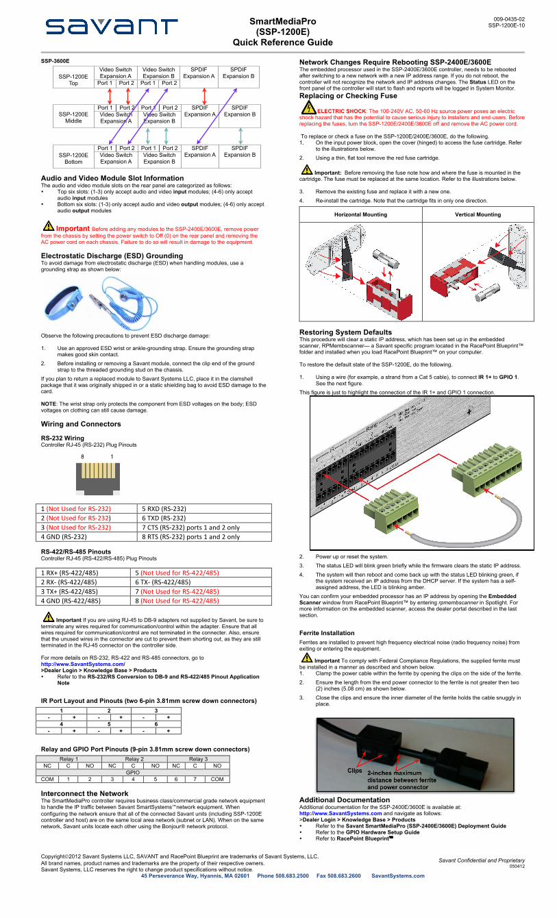
Front Panel 1 Standby Power
button Press the button for about five seconds to place the system in standby mode. Press the button again for about five seconds to take the system out of standby mode. To turn the power off for the entire system, use the switch on the rear panel.
2 Power LED Green indicates the system has adequate power and is operating normally. Red indicates the system is in standby mode. The controller hardware has power, but the embedded processor is shut off and in the standby mode. Off indicates that the system is not receiving power.
3 Status LED
Green indicates the host has evaluated the firmware currently running and determined it is up to date. Green flashing indicates the embedded system is ready (running with DHCP IP address), but the embedded processor has not established communications with the embedded system. Off indicates the embedded processor is resetting or is powered up and is booting the embedded firmware. Red indicates the host has determined the firmware needs to be updated but a problem occurred during the process that will initiate a reset. Red flashing indicates the embedded firmware is running but has not received a DHCP IP address. Amber indicates the host is currently updating the embedded firmware. Amber flashing indicates the embedded system has a valid link-local IP address and is waiting to connect to the host. Over Temperature or Hardware Failure If the controller overheats or has a hardware failure, the Status LED indication will be interrupted every three seconds with a solid red indication. For example, if the LED is flashing green when an over temperature or hardware failure occurs, the LED will flash green, solid red, etc. in 3-second intervals.
4 Video LED Off indicates the encrypted video content remains protected. The HDCP keys remain valid. Red flashing indicates the HDCP keys are invalid.
5 Video port LED Off indicates which video output port(s) do not have an error. Green indicates which video output port(s) have an error.
6 RS-232/422/485, IR, Relay and GPIO LEDs
Green indicates activity on the associated ports on the rear of the unit.
Specifications per SSP-1200E Environmental Temperature 32º to 104º F (0º to 40º C) Humidity 10% to 80% RH (non-condensing) Cooling 62 cubic feet per minute (CFM) recommended.
Note that each chassis has fans pushing 72 CFM. Maximum BTUs 1195 BTUs per hour Noise Normal Operation condition: 57 dB Average Power Maximum Power 350 Watt Power Supply 100-240V AC 50/60 Hz Dimensions and Weight Dimensions (H x W X D) 10.46 in x 17.32 in x 14.23 in (26.57 cm x 43.99 cm x 36.14 cm) Weight 54 lb/24.49 kg (Base Configuration/Shipping Weight) Rack Space 6U Compliance Safety and Emissions S-Mark/FCC Part 15/CE Mark/C-Tick RoHS Compliant
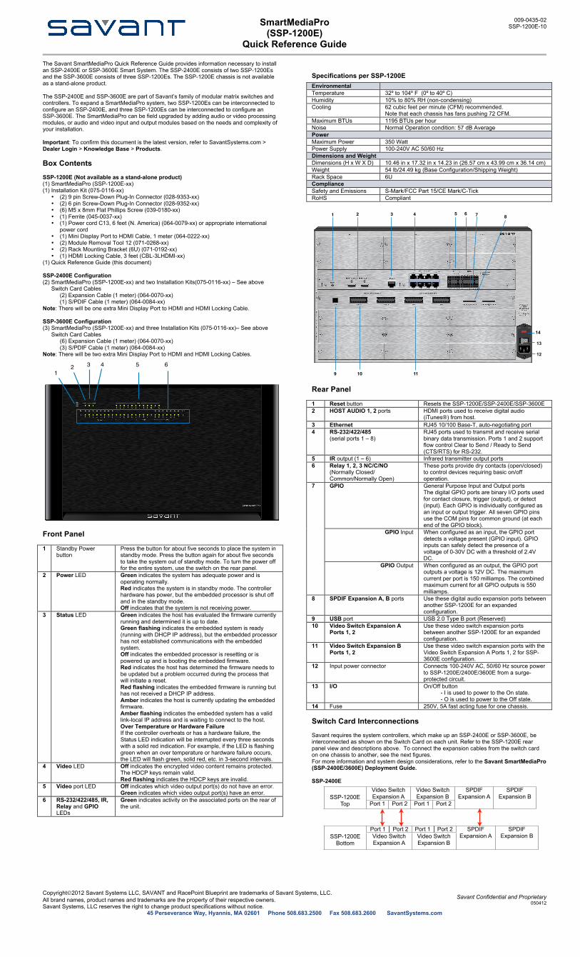
Rear Panel 1 Reset button Resets the SSP-1200E/SSP-2400E/SSP-3600E 2 HOST AUDIO 1, 2 ports HDMI ports used to receive digital audio
(iTunes®) from host. 3 Ethernet RJ45 10/100 Base-T, auto-negotiating port 4 RS-232/422/485
(serial ports 1 – 8) RJ45 ports used to transmit and receive serial binary data transmission. Ports 1 and 2 support flow control Clear to Send / Ready to Send (CTS/RTS) for RS-232.
5 IR output (1 – 6) Infrared transmitter output ports 6 Relay 1, 2, 3 NC/C/NO
(Normally Closed/ Common/Normally Open)
These ports provide dry contacts (open/closed) to control devices requiring basic on/off operation.
GPIO General Purpose Input and Output ports The digital GPIO ports are binary I/O ports used for contact closure, trigger (output), or detect (input). Each GPIO is individually configured as an input or output trigger. All seven GPIO pins use the COM pins for common ground (at each end of the GPIO block).
GPIO Input When configured as an input, the GPIO port detects a voltage present (GPIO input). GPIO inputs can safely detect the presence of a voltage of 0-30V DC with a threshold of 2.4V DC.
7
GPIO Output When configured as an output, the GPIO port outputs a voltage is 12V DC. The maximum current per port is 150 milliamps. The combined maximum current for all GPIO outputs is 550 milliamps.
8 SPDIF Expansion A, B ports Use these digital audio expansion ports between another SSP-1200E for an expanded configuration.
9 USB port USB 2.0 Type B port (Reserved) 10 Video Switch Expansion A
Ports 1, 2 Use these video switch expansion ports between another SSP-1200E for an expanded configuration.
11 Video Switch Expansion B Ports 1, 2
Use these video switch expansion ports with the Video Switch Expansion A Ports 1, 2 for SSP-3600E configuration.
12 Input power connector
Connects 100-240V AC, 50/60 Hz source power to SSP-1200E/2400E/3600E from a surge-protected circuit.
13 I/O On/Off button - I is used to power to the On state. - O is used to power to the Off state.
14 Fuse 250V, 5A fast acting fuse for one chassis. Switch Card Interconnections Savant requires the system controllers, which make up an SSP-2400E or SSP-3600E, be interconnected as shown on the Switch Card on each unit. Refer to the SSP-1200E rear panel view and descriptions above. To connect the expansion cables from the switch card on one chassis to another, see the next figures. For more information and system design considerations, refer to the Savant SmartMediaPro (SSP-2400E/3600E) Deployment Guide. SSP-2400E
61
42 3 5
321 5 74
9 10 11
86
14
13
12
SSP-1200E Top
Video Switch Expansion AVideo Switch Expansion A
Video SwitchExpansion BVideo SwitchExpansion B
SPDIFExpansion A
SPDIFExpansion BSSP-1200E
Top Port 1 Port 2 Port 1 Port 2
SPDIFExpansion A
SPDIFExpansion B
SSP-1200E Bottom
Port 1 Port 2 Port 1 Port 2 SPDIFExpansion A
SPDIFExpansion BSSP-1200E
BottomVideo Switch Expansion AVideo Switch Expansion A
Video SwitchExpansion BVideo SwitchExpansion B
SPDIFExpansion A
SPDIFExpansion B
SmartMediaPro
(SSP-1200E) Quick Reference Guide
009-0435-02 SSP-1200E-10
Copyright2012 Savant Systems LLC, SAVANT and RacePoint Blueprint are trademarks of Savant Systems, LLC. All brand names, product names and trademarks are the property of their respective owners. Savant Systems, LLC reserves the right to change product specifications without notice.
Savant Confidential and Proprietary 050412
45 Perseverance Way, Hyannis, MA 02601 Phone 508.683.2500 Fax 508.683.2600 SavantSystems.com
SSP-3600E
Audio and Video Module Slot Information The audio and video module slots on the rear panel are categorized as follows: • Top six slots: (1-3) only accept audio and video input modules; (4-6) only accept
audio input modules • Bottom six slots: (1-3) only accept audio and video output modules; (4-6) only accept
audio output modules
Important Before adding any modules to the SSP-2400E/3600E, remove power from the chassis by setting the power switch to Off (0) on the rear panel and removing the AC power cord on each chassis. Failure to do so will result in damage to the equipment. Electrostatic Discharge (ESD) Grounding To avoid damage from electrostatic discharge (ESD) when handling modules, use a grounding strap as shown below:
Observe the following precautions to prevent ESD discharge damage: 1. Use an approved ESD wrist or ankle-grounding strap. Ensure the grounding strap
makes good skin contact. 2. Before installing or removing a Savant module, connect the clip end of the ground
strap to the threaded grounding stud on the chassis. If you plan to return a replaced module to Savant Systems LLC, place it in the clamshell package that it was originally shipped in or a static shielding bag to avoid ESD damage to the card. NOTE: The wrist strap only protects the component from ESD voltages on the body; ESD voltages on clothing can still cause damage. Wiring and Connectors RS-232 Wiring Controller RJ-45 (RS-232) Plug Pinouts
1 (Not Used for RS-‐232) 5 RXD (RS-‐232) 2 (Not Used for RS-‐232) 6 TXD (RS-‐232) 3 (Not Used for RS-‐232) 7 CTS (RS-‐232) ports 1 and 2 only 4 GND (RS-‐232) 8 RTS (RS-‐232) ports 1 and 2 only RS-422/RS-485 Pinouts Controller RJ-45 (RS-422/RS-485) Plug Pinouts 1 RX+ (RS-‐422/485) 5 (Not Used for RS-‐422/485) 2 RX-‐ (RS-‐422/485) 6 TX-‐ (RS-‐422/485) 3 TX+ (RS-‐422/485) 7 (Not Used for RS-‐422/485) 4 GND (RS-‐422/485) 8 (Not Used for RS-‐422/485)
Important If you are using RJ-45 to DB-9 adapters not supplied by Savant, be sure to terminate any wires required for communication/control within the adapter. Ensure that all wires required for communication/control are not terminated in the connecter. Also, ensure that the unused wires in the connector are cut to prevent them shorting out, as they are still terminated in the RJ-45 connector on the controller side. For more details on RS-232, RS-422 and RS-485 connectors, go to http://www.SavantSystems.com/ >Dealer Login > Knowledge Base > Products • Refer to the RS-232/RS Conversion to DB-9 and RS-422/485 Pinout Application
Note
IR Port Layout and Pinouts (two 6-pin 3.81mm screw down connectors) 1 2 3
- + - + - + 4 5 6
- + - + - +
Relay and GPIO Port Pinouts (9-pin 3.81mm screw down connectors) Relay 1 Relay 2 Relay 3
NC C NO NC C NO NC C NO GPIO
COM 1 2 3 4 5 6 7 COM Interconnect the Network The SmartMediaPro controller requires business class/commercial grade network equipment to handle the IP traffic between Savant SmartSystems™network equipment. When configuring the network ensure that all of the connected Savant units (including SSP-1200E controller and host) are on the same local area network (subnet or LAN). When on the same network, Savant units locate each other using the Bonjour® network protocol.
Network Changes Require Rebooting SSP-2400E/3600E The embedded processor used in the SSP-2400E/3600E controller, needs to be rebooted after switching to a new network with a new IP address range. If you do not reboot, the controller will not recognize the network and IP address changes. The Status LED on the front panel of the controller will start to flash and reports will be logged in System Monitor. Replacing or Checking Fuse
ELECTRIC SHOCK: The 100-240V AC, 50-60 Hz source power poses an electric shock hazard that has the potential to cause serious injury to installers and end-users. Before replacing the fuses, turn the SSP-1200E/2400E/3600E off and remove the AC power cord. To replace or check a fuse on the SSP-1200E/2400E/3600E, do the following. 1. On the input power block, open the cover (hinged) to access the fuse cartridge. Refer
to the illustrations below. 2. Using a thin, flat tool remove the red fuse cartridge.
Important: Before removing the fuse note how and where the fuse is mounted in the cartridge. The fuse must be replaced at the same location. Refer to the illustrations below. 3. Remove the existing fuse and replace it with a new one. 4. Re-install the cartridge. Note that the cartridge fits in only one direction.
Horizontal Mounting Vertical Mounting
Restoring System Defaults This procedure will clear a static IP address, which has been set up in the embedded scanner, RPMembscanner— a Savant specific program located in the RacePoint Blueprint™ folder and installed when you load RacePoint Blueprint™ on your computer. To restore the default state of the SSP-1200E, do the following. 1. Using a wire (for example, a strand from a Cat 5 cable), to connect IR 1+ to GPIO 1.
See the next figure. This figure is just to highlight the connection of the IR 1+ and GPIO 1 connection.
2. Power up or reset the system. 3. The status LED will blink green briefly while the firmware clears the static IP address. 4. The system will then reboot and come back up with the status LED blinking green, if
the system received an IP address from the DHCP server. If the system has a self-assigned address, the LED is blinking amber.
You can confirm your embedded processor has an IP address by opening the Embedded Scanner window from RacePoint Blueprint™ by entering rpmembscanner in Spotlight. For more information on the embedded scanner, access the dealer portal described in the last section.
Ferrite Installation Ferrites are installed to prevent high frequency electrical noise (radio frequency noise) from exiting or entering the equipment.
Important To comply with Federal Compliance Regulations, the supplied ferrite must be installed in a manner as described and shown below. 1. Clamp the power cable within the ferrite by opening the clips on the side of the ferrite. 2. Ensure the length from the end power connector to the ferrite is not greater then two
(2) inches (5.08 cm) as shown below. 3. Close the clips and ensure the inner diameter of the ferrite holds the cable snuggly in
place.
Additional Documentation Additional documentation for the SSP-2400E/3600E is available at: http://www.SavantSystems.com and navigate as follows: >Dealer Login > Knowledge Base > Products • Refer to the Savant SmartMediaPro (SSP-2400E/3600E) Deployment Guide • Refer to the GPIO Hardware Setup Guide • Refer to RacePoint Blueprint™
SSP-1200E Top
Video Switch Expansion AVideo Switch Expansion A
Video SwitchExpansion BVideo SwitchExpansion B
SPDIFExpansion A
SPDIFExpansion BSSP-1200E
Top Port 1 Port 2 Port 1 Port 2
SPDIFExpansion A
SPDIFExpansion B
SSP-1200E Middle
Port 1 Port 2 Port 1 Port 2 SPDIFExpansion A
SPDIFExpansion BSSP-1200E
MiddleVideo Switch Expansion AVideo Switch Expansion A
Video SwitchExpansion BVideo SwitchExpansion B
SPDIFExpansion A
SPDIFExpansion B
SSP-1200E Bottom
Port 1 Port 2 Port 1 Port 2 SPDIFExpansion A
SPDIFExpansion BSSP-1200E
BottomVideo Switch Expansion AVideo Switch Expansion A
Video SwitchExpansion BVideo SwitchExpansion B
SPDIFExpansion A
SPDIFExpansion B


![Scanned with CamScanner2.336.7278-1 ssp r] 2.137.438.67 ssp 3.539.747 ssp pb 9.188.097 sds pe 3.941.456 ssds pb 2.962.728 ssp pb 3.470.194 ssp pb 3.714.010 ssp pb 28.250.988-4 detran](https://static.fdocuments.net/doc/165x107/5f66e8908127b2003314bb43/scanned-with-23367278-1-ssp-r-213743867-ssp-3539747-ssp-pb-9188097-sds.jpg)