
Belco Resources Equipment SSP-250 SSP-400 Poly …tarrivermfg.com/index_htm_files/SSP-250 SSP-400...
20
Operator’s Manual Poly Fertilizer Spreaders SSP-250 - SSP-400 Publication: February 2011
Transcript of Belco Resources Equipment SSP-250 SSP-400 Poly …tarrivermfg.com/index_htm_files/SSP-250 SSP-400...

Operator’s Manual
Poly Fertilizer Spreaders
SSP-250 - SSP-400
Publication: February 2011

2

3
TABLE OF CONTENTS
INTRODUCTION.........................................................................................................................................................4
SAFETY........................................................................................................................................................................4
SAFETY SIGNAL WORDS .........................................................................................................................................5
GENERAL SAFETY GUIDELINES............................................................................................................................5
SAFETY DECAL CARE ..............................................................................................................................................6
BEFORE OPERATION ................................................................................................................................................6
DURING OPERATION................................................................................................................................................7
HIGHWAY AND TRANSPORT OPERATIONS ........................................................................................................8
ASSEMBLY..................................................................................................................................................................9
OPERATION ..............................................................................................................................................................11
ATTACHING TO THE TRACTOR ...........................................................................................................................11
SHORTENING A PTO DRIVELINE .........................................................................................................................11
MAINTENANCE........................................................................................................................................................12
SPREADING CHART ................................................................................................................................................13
PARTS BREAKDOWN..............................................................................................................................................15
LIMITED WARRANTY.............................................................................................................................................17
WARRANTY REGISTRATION FORM & INSPECTION REPORT .......................................................................19

4
INTRODUCTION
Thank you for purchasing your Belco Resources Equipment fertilizer spreader. Your fertilizer spreader is design to be used on Cat. 1 tractors and at 540. It is important to properly maintain in keep in place all safety guards and shields that came with your spreader.
SAFETY Read and understand this manual and all safety signs before operating and maintaining. Review the safety in-structions and precautions annually. TAKE NOTE! THIS SAFETY ALERT SYMBOL FOUND THROUGHOUT THIS MANUAL IS USED TO CALL YOUR ATTENTION TO INSTRUCTIONS INVOLVING YOUR PERSONAL SAFETY AND THE SAFETY OF OTHERS. FAILURE TO FOLLOW THESE INSTRUCTIONS CAN RESULT IN INJURY OR DEATH.
THIS SYMBOL MEANS
ATTENTION! BECOME ALERT!
YOUR SAFETY IS INVOLVED!
5
SAFETY SIGNAL WORDS
Safety of the operator is one of the main concerns in designing and developing a new piece of equipment. Designers and manufacturers build in as many safety features as possible. However, every year many accidents occur which could have been avoided by a few seconds of thought and a more careful approach to handling equipment. You, the operator, can avoid many accidents by observing the following precautions in this section. To avoid personal injury, study the following precautions and insist those working with you, or for you, follow them. Replace any CAUTION, WARNING, DANGER or instruction safety decal that is not readable or is missing. Location of such decals is indicated in this booklet. Do not attempt to operate this equipment under the influence of drugs or alcohol. Review the safety instructions with all users annually. This equipment is dangerous to children and persons unfamiliar with its operation. The operator should be a responsible adult familiar with farm machinery and trained in this equipment’s operations. Do not allow persons to operate or assemble this unit until they have read this manual and have developed a thorough understanding of the safety precautions and of how it works. To prevent injury or death, use a tractor equipped with a Roll Over Protective System (ROPS). Do not paint over, remove or deface any safety signs or warning decals on your equipment. Observe all safety signs and practice the instructions on them. Never exceed the limits of a piece of machinery. If its ability to do a job, or to do so safely, is in question - DON’T TRY IT.
Note the use of the signal words DANGER, WARNING and CAUTION with the safety messages. The appropriate signal word for each has been selected using the following guidelines:
DANGER: Indicates an imminently hazardous situation that, if not avoided, will result in death or serious injury. This signal word is to be limited to the most extreme situations typically for machine components which, for functional purposes, cannot be guarded.
WARNING: Indicates a potentially hazardous situation that, if not avoided, could result in death or serious injury, and includes hazards that are exposed when guards are removed. It may also be used to alert against unsafe practices.
CAUTION: Indicates a potentially hazardous situation that, if not avoided, may result in minor or moderate injury. It may also be used to alert against unsafe practices.
GENERAL SAFETY GUIDELINES

6
• Keep safety signs clean and legible at all times. • Replace safety signs that are missing or have become illegible. • Replaced parts that displayed a safety sign should also display the current sign. • Safety signs are available from your Distributor or Dealer Parts Department or the factory.
How to Install Safety Signs: • Be sure that the installation area is clean and dry. • Decide on the exact position before you remove the backing paper. • Remove the smallest portion of the split backing paper. • Align the decal over the specified area and carefully press the small portion with the exposed sticky backing
in place. • Slowly peel back the remaining paper and carefully smooth the remaining portion of the decal in place. • Small air pockets can be pierced with a pin and smoothed out using the piece of decal backing paper.
• Carefully study and understand this manual. • Do not wear loose-fitting clothing, which may catch in moving parts. • Always wear protective clothing and substantial shoes. • Assure that all tires are inflated evenly. • Give the unit a visual inspection for any loose bolts, worn parts or cracked welds, and make necessary repairs.
Follow the maintenance safety instructions included in this manual. • Be sure that there are no tools lying on or in the equipment. • Do not use the unit until you are sure that the area is clear, especially children and animals.
• Don’t hurry the learning process or take the unit for granted. Ease into it and become familiar with your new equipment.
• Practice operation of your equipment and its attachments. Completely familiarize yourself and other opera-
tors with its operation before using. • Use a tractor equipped with a Roll Over Protective System (ROPS) and fasten your seat belt prior to starting
the engine.
SAFETY DECAL CARE
BEFORE OPERATION
7
• The manufacturer does not recommend usage of tractor with ROPS removed. • Move tractor wheels to the widest recommended settings to increase stability. • Securely attach to towing unit. Use a high strength, appropriately sized hitch pin with a mechanical retainer
and attach safety chain. • Do not allow anyone to stand between the tongue or hitch and the towing vehicle when backing up to the
equipment.
• Children should not be allowed on the product.
• Clear the area of small children and bystanders before moving the feeder.
• If using a towing unit, securely attach feeder by using a hardened 3/4” pin, a metal retainer, and safety chains if required. Shift towing unit to a lower gear before going down steep downgrades, thus using the engine as a retarding force. Keep towing vehicle in gear at all times. Slow down for corners and rough ter-rain.
• Make sure you are in compliance with all local and state regulations regarding transporting equipment on public roads and highways. Lights and slow moving signs must be clean and visible by overtaking or on-coming traffic when feeder is transported.
• Beware of bystanders, particularly children! Always look around to make sure that it is safe to start the
engine of the towing vehicle or move the unit. This is particularly important with higher noise levels and quiet cabs, as you may not hear people shouting.
• NO PASSENGERS ALLOWED - Do not carry passengers anywhere on, or in, the tractor or equipment,
except as required for operation. • Keep hands and clothing clear of moving parts.
• Do not clean, lubricate or adjust your equipment while it is moving.
• When halting operation, even periodically, set the tractor or towing vehicle brakes, disengage the PTO, shut off the engine and remove the ignition key.
• Be especially observant of the operating area and terrain - watch for holes, rocks or other hidden hazards. Always inspect the area prior to operation.
• DO NOT operate near the edge of drop-offs or banks. • DO NOT operate on steep slopes as overturn may result. • Operate up and down (not across) intermediate slopes. Avoid sudden starts and stops.
DURING OPERATION

8
• Adopt safe driving practices: ⇒ Keep the brake pedals latched together at all times. NEVER USE INDEPENDENT BRAKING WITH MACHINE IN TOW AS LOSS OF CONTROL AND/OR UPSET OF UNIT CAN RESULT. ⇒ Always drive at a safe speed relative to local conditions and ensure that your speed is low enough for an emer-
gency stop to be safe and secure. Keep speed to a minimum. ⇒ Reduce speed prior to turns to avoid the risk of overturning. ⇒ Avoid sudden uphill turns on steep slopes. ⇒ Always keep the tractor or towing vehicle in gear to provide engine braking when going downhill. Do not coast. ⇒ Do not drink and drive! • Comply with state and local laws governing highway safety and movement of farm machinery on public roads. • Use approved accessory lighting flags and necessary warning devices to protect operators of other vehicles on
the highway during daylight and nighttime transport. Various safety lights and devices are available from your dealer.
• The use of flashing amber lights is acceptable in most localities. However, some localities prohibit their use.
Local laws should be checked for all highway lighting and marking requirements. • When driving the tractor and equipment on the road or highway under 40 kph (20 mph) at night or during the
day, use flashing amber warning lights and a slow moving vehicle (SMV) identification emblem. • Plan your route to avoid heavy traffic. • Be a safe and courteous driver. Always yield to oncoming traffic in all situations, including narrow bridges, in-
tersections, etc.
• Be observant of bridge loading ratings. Do not cross bridges rated lower than the gross weight as which you are operating.
• Watch for obstructions overhead and to the side while transporting. • Always operate equipment in a position to provide maximum visibility at all times. Make allowances for in-
creased length and weight of the equipment when making turns, stopping the unit, etc. • Pick the levelest possible route when transporting across fields. Avoid the edges of ditches or gullies and steep
hillsides. • Be extra careful when working on inclines. • Maneuver the tractor or towing vehicle at safe speeds. • Avoid overhead wires or other obstacles. Contact with overhead lines could cause serious injury or death. • Avoid loose fill, rocks and holes; they can be dangerous for equipment operation or movement. • Allow for unit length when making turns. • Operate the towing vehicle from the operator’s seat only. • Never stand alongside of unit with engine running or attempt to start engine and/or operate machine while stand-
ing alongside of unit. • Never leave running equipment attachments unattended. • As a precaution, always recheck the hardware on equipment following every 100 hours of operation. Correct all
problems. Follow the maintenance safety procedures.
HIGHWAY AND TRANSPORT OPERATIONS
9
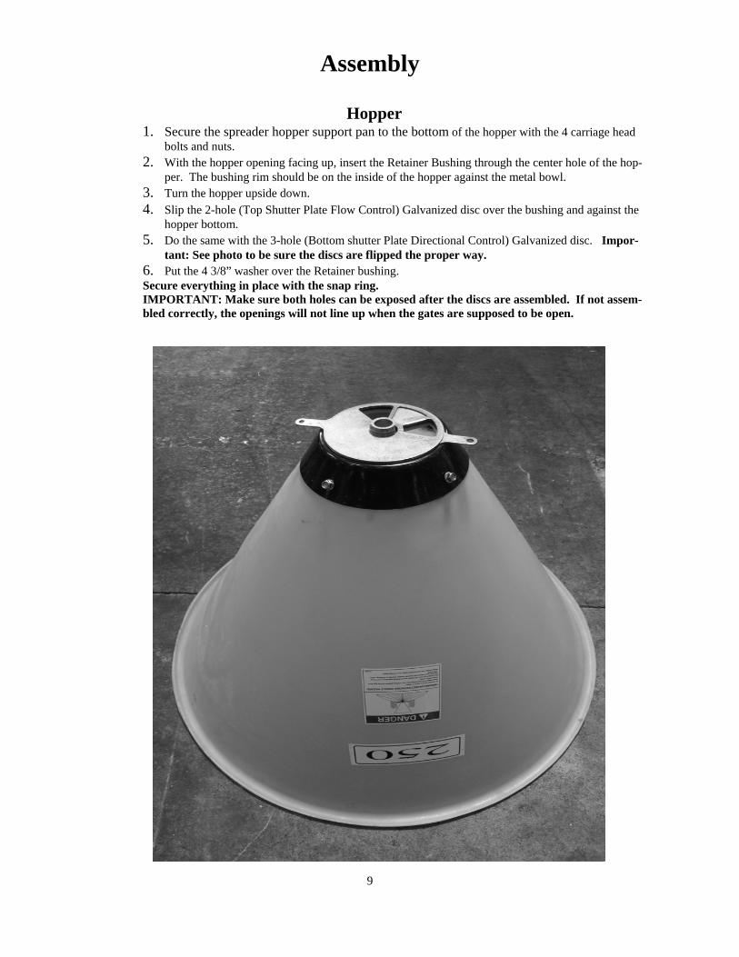
Hopper 1. Secure the spreader hopper support pan to the bottom of the hopper with the 4 carriage head
bolts and nuts. 2. With the hopper opening facing up, insert the Retainer Bushing through the center hole of the hop-
per. The bushing rim should be on the inside of the hopper against the metal bowl. 3. Turn the hopper upside down. 4. Slip the 2-hole (Top Shutter Plate Flow Control) Galvanized disc over the bushing and against the
hopper bottom. 5. Do the same with the 3-hole (Bottom shutter Plate Directional Control) Galvanized disc. Impor-
tant: See photo to be sure the discs are flipped the proper way. 6. Put the 4 3/8” washer over the Retainer bushing. Secure everything in place with the snap ring. IMPORTANT: Make sure both holes can be exposed after the discs are assembled. If not assem-bled correctly, the openings will not line up when the gates are supposed to be open.
Assembly
10
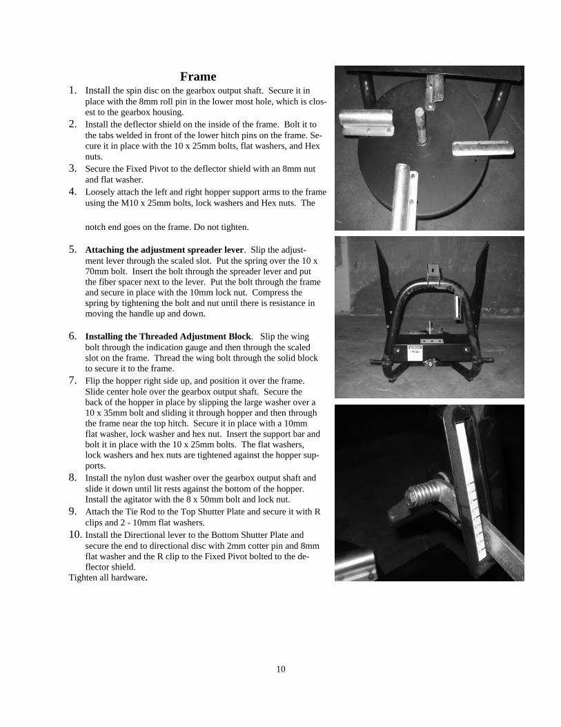
Frame 1. Install the spin disc on the gearbox output shaft. Secure it in
place with the 8mm roll pin in the lower most hole, which is clos-est to the gearbox housing.
2. Install the deflector shield on the inside of the frame. Bolt it to the tabs welded in front of the lower hitch pins on the frame. Se-cure it in place with the 10 x 25mm bolts, flat washers, and Hex nuts.
3. Secure the Fixed Pivot to the deflector shield with an 8mm nut and flat washer.
4. Loosely attach the left and right hopper support arms to the frame using the M10 x 25mm bolts, lock washers and Hex nuts. The
notch end goes on the frame. Do not tighten.
5. Attaching the adjustment spreader lever. Slip the adjust-ment lever through the scaled slot. Put the spring over the 10 x 70mm bolt. Insert the bolt through the spreader lever and put the fiber spacer next to the lever. Put the bolt through the frame and secure in place with the 10mm lock nut. Compress the spring by tightening the bolt and nut until there is resistance in moving the handle up and down.
6. Installing the Threaded Adjustment Block. Slip the wing bolt through the indication gauge and then through the scaled slot on the frame. Thread the wing bolt through the solid block to secure it to the frame.
7. Flip the hopper right side up, and position it over the frame. Slide center hole over the gearbox output shaft. Secure the back of the hopper in place by slipping the large washer over a 10 x 35mm bolt and sliding it through hopper and then through the frame near the top hitch. Secure it in place with a 10mm flat washer, lock washer and hex nut. Insert the support bar and bolt it in place with the 10 x 25mm bolts. The flat washers, lock washers and hex nuts are tightened against the hopper sup-ports.
8. Install the nylon dust washer over the gearbox output shaft and slide it down until lit rests against the bottom of the hopper. Install the agitator with the 8 x 50mm bolt and lock nut.
9. Attach the Tie Rod to the Top Shutter Plate and secure it with R clips and 2 - 10mm flat washers.
10. Install the Directional lever to the Bottom Shutter Plate and secure the end to directional disc with 2mm cotter pin and 8mm flat washer and the R clip to the Fixed Pivot bolted to the de-flector shield.
Tighten all hardware.
11
Operation
Attaching to the tractor 1. With the Fertilizer Spreader on a level surface, back the Cat. 1 tractor so the tractor lift arms are even with the
fertilizer spreader lower hitch pins. Lower or raise the tractor hitch arms until the 7/8” bushing in the arm is level with the hitch pins. Be sure nothing is between the tractor and the cutter before backing up.
2. Insert the lower link hitch hole of the tractor’s lift arm over the implement’s hitch pin. 3. Secure the lift arm in place by using a 7/16” lynch pin or other fastener. 4. Repeat with the other arm. 5. Connect the driveline to the tractor’s PTO output shaft. Secure it in place with the bolt supplied with the
driveline. 6. Connect the tractor top link to the upper pivot hitch of the fertilizer spreader. 7. Start the tractor and slowly raise the fertilizer spreader. Check for drawbar interference. Be sure that the PTO
driveline does not bottom out when lifting the fertilizer spreader to it’s maximum height. If it does appear that it could bottom out, it is necessary to shorten the PTO driveline. (See Shortening a PTO Driveline section). Ensure that in the working position there is an overlap of a minimum of 1/3 the length of each profile.
Shortening a PTO Driveline 1. With the implement attached to the tractor’s three point hitch, and the PTO driveline not installed, separate
the PTO driveline. Attach the implement end to the implement and the other end to the tractor PTO input shaft.
2. Raise the implement by using the tractor’s hydraulic 3-point hitch to it’s maximum lift height. 3. Hold the half shafts next to each other and mark them so each end is approximately ½” from hitting the end of
the telescopic profiles. 4. Shorten the inner and out guard tubes equally. 5. Shorten the inner and outer profiles by the same length as the guard tubes. Using a rattail file, round off all
sharp edges and burrs. Grease the telescopic profile generously before reassembling.
Do not shorten too much, the proper overlap is a minimum of 1/3 the length of each profile. Spreading Height Before operating the spreader, make sure that the spreading disc is set to the horizontal position and it is about 30” from ground level. Spreading with revolving vanes. Since fertilizers vary with respect to weights and density, in order to obtain a perfect spreading it may be necessary to adjust the vanes in order to compensate for these differences. The vanes are usually set to the center position. By moving the vanes forward, distribution is increased towards the left side of the tractor operator, moving them backwards causes distribution to be increased towards the right. Left– Center – Right Spreader pattern A simple adjustment of the lower lever allows directioning of the spreader pattern towards the right , center or left of the tractor Removal and Storage After finishing, remove the spreader from the tractor. 1. Put the PTO driveline in a safe location so it will not become damaged. Wash out the spreader, removing all fertilizer or other material.
12
• Following operation, or when unhitching, stop the tractor or towing vehicle, set the brakes, disengage the PTO
and all power drives, shut off the engine and remove the ignition keys. • Store the unit in an area away from human activity. • Do not park equipment where it will be exposed to livestock for long periods of time. Damage and livestock
injury could result. • Do not permit children to play on or around the stored unit. • Make sure all parked machines are on a hard, level surface and engage all safety devices. • Wheel chocks may be needed to prevent unit from rolling.
• Good maintenance is your responsibility. Poor maintenance is an invitation to trouble. • Make sure there is plenty of ventilation. Never operate the engine of the towing vehicle in a closed building.
The exhaust fumes may cause asphyxiation. • Be certain all moving parts on attachments have come to a complete stop before attempting to perform mainte-
nance. • Always use the proper tools or equipment for the job at hand. • Use extreme caution when making adjustments. • Never replace hex bolts with less than grade five bolts unless otherwise specified. • After servicing, be sure all tools, parts and service equipment are removed. • Where replacement parts are necessary for periodic maintenance and servicing, genuine factory replacement
parts must be used to restore your equipment to original specifications. The manufacturer will not claim respon-sibility for use of unapproved parts and/or accessories and other damages as a result of their use.
• If equipment has been altered in any way from original design, the manufacturer does not accept any liability for injury or warranty.
MAINTENANCE Although the hopper of your spreader is fabricated with polypropylene, and therefore impervious to rust and corro-sion, it is very important that the other parts of the spreader be kept clean due to the corrosive properties of fertilizers.
The
gearbox is sealed and filled with grease so not maintenance is necessary.
FOLLOWING OPERATION
Item Interval
PTO shaft grease zerks Grease weekly
PTO shaft telescopic tubing Grease every 40 hours
Clean spreader After each use.

13
Fertilizer Type Spread Width MPH LBS PER ACRE
Gate setting
1.5 2 2.5 3 3.5 4 4.5 5 5.5 6 6.5 7
Granular Fertilizer 39
1 174 285 484 815 1052 1326 1554 1870 2105 2414 2622 2919
2.5 84 121 202 336 435 545 640 762 854 987 1071 1172
5 46 60 106 176 222 277 320 392 436 494 535 596
7.5 29 40 92 121 151 191 216 260 294 336 365 400
10 17 30 52 86 113 136 166 197 231 253 279 295
Medium Crystalline Fertilizer
26
1 330 546 1007 1632 2019 2587 3024 3603 4033 4476 4908 5407
2.5 115 219 412 661 816 1053 1221 1446 1621 1801 1973 2174
5 68 112 209 329 416 534 614 730 821 907 989 1092
7.5 44 76 140 223 280 364 415 490 546 606 664 728
10 30 54 100 171 208 275 318 363 408 455 496 549
Calcium Cyanamid & Similar
32
1 275 750 1104 1636 2020 1844 2868 3345 4289
2.5 109 300 453 662 809 994 1158 1343 1508
5 58 149 229 297 407 495 584 672 755
7.5 37 99 148 218 272 333 388 449 502
10 26 73 112 166 204 251 289 336 376
Ammonium Sulph. (CR) 10
1 142 565 924 1391 1779 2199 2607 3061 3355 3767 4039 4521
2.5 61 224 373 557 716 886 1040 1228 1347 1512 1621 1810
5 28 114 188 281 362 444 519 615 671 757 809 909
7.5 23 73 122 189 241 295 348 418 451 508 544 607
10 15 58 94 143 180 222 262 308 336 378 410 453
Thomas Metal 20
1 2262 5037 6670 6929
4 572 1277 1685 1736
7 290 537 843 869
12 195 427 297 583
Spreading Charts
14
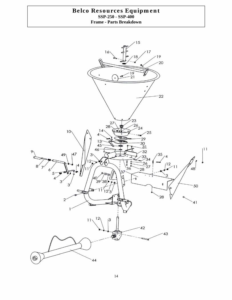
Belco Resources Equipment SSP-250 - SSP-400
Frame - Parts Breakdown

15
Belco Resources Equipment SSP-250 - SSP-400
Frame - Parts Breakdown
Part No. Part # Description Qty 1 5SB16153 Base Assembly 1 2 5SB3016 Bolt, Hex Head M10x20,Zinc 2 3 5SB07015 Flat Washer Zinc Plated 10mm 5 4 5SB12048 R Clips 4 5 5SB19287 Tie Rod 1 6 5SB19286 Lever 1 7 5SB19306 Spreader Spring 1 8 5SB06099 Bolt, Hex Head M10x70,Zinc 1
10 5SB19312 Hopper Support Arm (Right Side) 1 11 5SB11005 Hex Head Nut 10 x 1.5 14 12 5SB07001 Split Type 10mm Lockwasher 10 13 5SB19299 Directional Lever 1 14 5SB06103 Shutter Adjustment Pivot Joint 1 15 5SB19297 Agitator 1 16 5SB06097 Hex Head Bolt 8 x 2.5 x 45 1 17 5SB11056 8mm Nylon Locking Nut 1 18 5SB07090 25 x 60 x 3.o Nylon Washer 1 19 5SB06112 Bolt, Carridge, M10x25, Zinc 5 20 5SB19227 Bar - Hopper reinforcement 1 21 5SB07073 Hopper Support Washer 1 22 5SB19394 Hopper 1 23 5SB04131A Retainer Bushing 1 24 5SB16152 Hopper Support Pan 1 25 5SB3010 Bolt Carridge,M8x25, Zinc 6 26 5SB07075 8mm Flat Washer Zinc Plated 14 27 5SB3012 Washer,Lock,8mm, Zinc 14 28 5SB11045 Hex Head Nut 8 x 1.25 15 29 5SB19300 Top Shutter Plate (Flow Control) 1 30 5SB19301 Bottom Shutter Plate (Directional) 1 31 5SB06095 Hex Head Bolt 8 x 1.25 x 16 8 32 5SB19291 Distributor Vane 4 33 5SB3013 Roll Pin,ø8*40, 1 34 5SB3014 Roll Pin,ø6*40, 1 35 5SB12055 Lever, Fixed Pivot 1 36 5SB19292 Spreader Disc 1 37 5SB19296 Front Shield 1 38 5SB19307 Threaded Adj. Block 1 39 5SB19308 Gauge Pointer 1 40 5SB06094 Thumb Screw 1 41 5SB06063 Bolt Hex Head M10x25, Zinc 4 42 5SB01429 Gearbox 1 43 5SB06096 Hex Bolt 10 x 1.5 x 110 3 44 5SB3000 PTO Assembly (complete) 1 45 5SB07079A Flat Washer - Hardened 1 46 5SB21036 Snap Ring 1 47 5SB11019 M10 Lock Nut 1 48 5SB3015 Washer,Lock 4 49 5SB10129 Adjustment Lever Washer, Bakelite 1 50 5SB19294 Hopper Support Arm (Left Side) 1

16
Belco Resources Equipment SSP-250 - SSP-400
PTO Shaft - Parts Breakdown
Position Part # Description Qty 1 5SB3001 Yoke 2 2 5SB3002 Inner Yoke complete 1 3 5SB3003 Outer Yoke complete 1 4 5SB3004 Inner PTO Guard Complete 1 5 5SB3005 Outer PTO Guard Complete 1 6 5SB3006 Cross & Bearing 2 7 5SB3007 Safety Chain 2 5SB3000 PTO Shaft Complete

17
LIMITED WARRANTY Belco Resources Equipment warrants to the original purchaser of any new piece of machinery from Belco Resources Equipment, purchased from an authorized Belco Resources Equip-ment dealer, that the equipment be free from defects in material and workmanship for a period of one (1) year for non-commercial, state, and municipalities’ use, ninety (90) days for commercial use from date of retail sale. Warranty for rental purposes is thirty (30) days. The obligation of Belco Resources Equipment to the purchaser under this warranty is limited to the repair or replacement of defective parts. Replacement or repair parts installed in the equipment covered by this limited warranty are war-ranted for ninety (90) days from the date of purchase of such part or to the expiration of the applica-ble new equipment warranty period, whichever occurs later. Warranted parts shall be provided at no cost to the user at an authorized Belco Resources Equipment dealer during regular working hours. Belco Resources Equipment reserves the right to inspect any equipment or parts which are claimed to have been defective in material or workmanship. This limited warranty does not apply to and excludes wear items such as shear pins, tires, tubes knives, blades or other wear items. Oil or grease is not covered by this warranty.
All obligations of Belco Resources Equipment under this limited warranty shall be ter-minated if: Proper service is not preformed on the machine The machine is modified or altered in any way. The machine is being used or has been used for purposes other than those
for which the machine was intended. DISCLAIMER OF IMPLIED WARRANTIES & CONSEQUENTIAL DAMAGES Belco Resources Equipment obligation under this limited warranty, to the extent
allowed by law, is in lieu of all warranties, implied or expressed, including im-plied warranties of merchantability and fitness for a particular purpose and any liability for incidental and consequential damages with respect to the sale or use of the items warranted. Such incidental and consequential damages shall include but not be limited to: transportation charges other than normal freight charges; cost of installation other than cost approved by Belco Resources Equipment; duty; taxes; charges for normal service or adjustment; loss of crops or any other loss of income; rental of substitute equipment, expenses due to loss, damage, detention or delay in the delivery.

18

19
WARRANTY REGISTRATION FORM & INSPECTION REPORT This form must be filled out by the dealer and signed by both dealer and customer at time of delivery.
Customer name ____________________________ Dealer name _______________________________
Address __________________________________ Address ___________________________________
City, state, code ____________________________ City, state, code ____________________________
Phone number ______________________________ Dealer Account # ____________________________
Tractor Make ______________________________
Model ______________ HP __________________
Type of Application (Commercial Maintenance, Private Homeowner, Landscaping, Farm, etc) __________________________________________
Model ____________________________________
Serial Number ______________________________
Delivery Date ______________________________
DEALER INSPECTION REPORT CUSTOMER WARRANTY UNDERSTANDING
_______ Tightened All Hardware _______ Safety Guards In Place _______ Safety Decals In Place _______ Fittings Greased _______ Oil In Gearbox _______ Bolts Correctly Torqued _______ Unit Attached to Tractor _______ Field Adjusted _______ Operator’s Manual Is Present _______ Review operating and safety instructions
I hereby acknowledge that: I have received and accepted delivery of the machine de-scribed. The equipment was thoroughly inspected for loose and/or missing parts and has been adjusted in accordance with the Pre-Delivery Checklist. I have read and understand the nature and extent of the warranty and understand clearly that there were and are no other representations of warranties, either expressed or implied, made by any person. I have been advised on proper operation, maintenance and lubrication prodecure of this equipment. I have been instructed on and do understand the applica-tion, limitation and capacities this equipment was designed and recommended for, all as described in the Operator’s Manual and Product Literature provided by Belco Re-sources Equipment.
I have thoroughly instructed the buyer on the above-described equipment; review included the operator’s manual content, equipment care, adjustments, safe operation and applicable warranty policy.
Date _______________________ Dealer’s signature _______________________________________
The above equipment and operator’s manual have been received by me, and I have been thoroughly in-structed as to care, adjustments, safe operation and applicable warranty policy.
Date _______________________ Customer’s signature ____________________________________
Mail to: Belco Resources Equipment Division P.O. Box 8164 Rocky Mount, NC 27804

20
Increasing agricultural productivity since 1974 Belco Resources Equipment
P.O. Box 8164 Rocky Mount, NC 27804 www.BR-Equipment.com
Tel: 252-442-0700 Fax: 252-442-0787 Sales@BRGlimited