
Simplified Projectile Swerve Solution for General Control ...
7
Simplified Projectile Swerve Solution for General Control Inputs Douglas Ollerenshaw ∗ Oregon State University, Corvallis, Oregon 97331 and Mark Costello † Georgia Institute of Technology, Atlanta, Georgia 30332 DOI: 10.2514/1.34252 The swerve response of fin- and spin-stabilized projectiles to control mechanism inputs is sometimes not intuitive. This paper seeks to explain the basic parameters that govern the swerve of projectiles excited by control inputs. By modeling the overall effect of a generalized control mechanism as a nonrolling reference frame force applied to a point on the projectile, general expressions for swerve are obtained in terms of basic vehicle parameters. These compact expressions are used to show that maximum swerve response for a fin-stabilized projectile is achieved when the force is applied near the nose of the projectile, whereas maximum swerve response for a spin-stabilized projectile is achieved when the force is applied near the base of the projectile. Nomenclature C MQ = pitch damping aerodynamic coefficient C NA = normal force aerodynamic coefficient C YPA = Magnus force aerodynamic coefficient D = projectile reference diameter F c = magnitude of the applied control force g = gravity I P = pitch moment of inertia measured around an axis centered at the projectile center of mass and perpendicular to the axis of symmetry I R = roll moment of inertia measured about the projectile axis of symmetry m = mass of the projectile p = projectile roll rate expressed in the body frame ~ q, ~ r = projectile pitch and yaw rates expressed in the no- roll frame R = magnitude of the swerve response s = dimensionless arc length ~ u, ~ v, ~ w = projectile velocity components expressed in the no- roll frame V = total velocity x, y, z = projectile position in inertial space Y c , Z c = y and z components applied control force expressed in no-roll frame SLC = station line distance from the projectile mass center to the point of application of the control force SLM = station line distance from the projectile mass center to the point of application of the Magnus force SLP = station line distance from the projectile mass center to the center of pressure FR , FI = real and imaginary parts of the fast-mode epicyclic eigenvalues SR , SI = real and imaginary parts of the slow-mode epicyclic eigenvalues = atmospheric density R = phase shift of the swerve response , , = projectile roll, pitch, and yaw angles = denotes variables expressed in the projectile no-roll frame 0 = prime denotes variables differentiated with respect to dimensionless arc length I. Introduction T HE continuing development of microelectromechanical systems (MEMS) is pointing to the possibility of mounting complete sensor systems on medium- and small-caliber projectiles as part of an actively controlled smart munition. Two important technical challenges in achieving this goal are the development of small, rugged, sensor suites and control mechanisms. There is currently a flurry of activity to create innovative physical control mechanisms. Concepts include pulse jets, squibs, synthetic jets [1– 3], drag brakes [4,5], deployable pins [6,7], moveable nose [8], moveable canards [9], dual-spin projectiles [10,11], ram air deflection [12], and internal translating mass [13], to name a few. Although the preceding physical control mechanisms are very diverse, there is a common theme between them all: each exerts a force and/or moment on the projectile. Moreover, because trajectories are shaped relative to ground coordinates, the forces and moments are effectively applied in a nonrolling reference frame and can often be modeled as constant point forces applied to the projectile body. Although the uncontrolled dynamics of projectiles (both fin-stabilized and spin-stabilized) have been extensively studied in the ballistics community, issues with regard to control response have received considerably less attention due to the lack of practical application of control technology to spinning projectiles. Using projectile linear theory, this paper analytically investigates several aspects of the response of a spinning projectile to a constant control force in the nonrolling reference frame. Simple expressions result for the swerve-response magnitude and phase angle in terms of basic physical mass properties, aerodynamic characteristics, and the state of the air vehicle. These expressions provide a means toward deeper understanding of the underlying factors driving the control response of projectiles, helping smart-weapon designers to create more capable weapon systems. II. Simplified Analytical Swerve Solution A six-degree-of-freedom (6-DOF) rigid-body dynamic model used to simulate the trajectory of a projectile in atmospheric flight is Received 27 August 2007; revision received 30 November 2007; accepted for publication 6 December 2007. Copyright © 2007 by the American Institute of Aeronautics and Astronautics, Inc. All rights reserved. Copies of this paper may be made for personal or internal use, on condition that the copier pay the $10.00 per-copy fee to the Copyright Clearance Center, Inc., 222 Rosewood Drive, Danvers, MA 01923; include the code 0731-5090/08 $10.00 in correspondence with the CCC. ∗ Department of Mechanical Engineering; currently Consulting Engineer, Earthly Dynamics LLC, Atlanta, GA 30327. † Sikorsky Associate Professor, School of Aerospace Engineering. Associate Fellow AIAA. JOURNAL OF GUIDANCE,CONTROL, AND DYNAMICS Vol. 31, No. 5, September–October 2008 1259
Transcript of Simplified Projectile Swerve Solution for General Control ...

Simplified Projectile Swerve Solution for GeneralControl Inputs
Douglas Ollerenshaw∗
Oregon State University, Corvallis, Oregon 97331
and
Mark Costello†
Georgia Institute of Technology, Atlanta, Georgia 30332
DOI: 10.2514/1.34252
The swerve response of fin- and spin-stabilized projectiles to control mechanism inputs is sometimes not intuitive.
This paper seeks to explain the basic parameters that govern the swerve of projectiles excited by control inputs. By
modeling the overall effect of a generalized control mechanism as a nonrolling reference frame force applied to a
point on the projectile, general expressions for swerve are obtained in terms of basic vehicle parameters. These
compact expressions are used to show thatmaximum swerve response for a fin-stabilized projectile is achieved when
the force is applied near the nose of the projectile, whereasmaximum swerve response for a spin-stabilized projectile
is achieved when the force is applied near the base of the projectile.
Nomenclature
CMQ = pitch damping aerodynamic coefficientCNA = normal force aerodynamic coefficientCYPA = Magnus force aerodynamic coefficientD = projectile reference diameterFc = magnitude of the applied control forceg = gravityIP = pitch moment of inertia measured around an axis
centered at the projectile center of mass andperpendicular to the axis of symmetry
IR = roll moment of inertia measured about the projectileaxis of symmetry
m = mass of the projectilep = projectile roll rate expressed in the body frame~q, ~r = projectile pitch and yaw rates expressed in the no-
roll frameR = magnitude of the swerve responses = dimensionless arc length~u, ~v, ~w = projectile velocity components expressed in the no-
roll frameV = total velocityx, y, z = projectile position in inertial spaceYc, Zc = y and z components applied control force expressed
in no-roll frame�SLC = station line distance from the projectile mass center
to the point of application of the control force�SLM = station line distance from the projectile mass center
to the point of application of the Magnus force�SLP = station line distance from the projectile mass center
to the center of pressure�FR, �FI = real and imaginary parts of the fast-mode epicyclic
eigenvalues�SR, �SI = real and imaginary parts of the slow-mode epicyclic
eigenvalues
� = atmospheric density�R = phase shift of the swerve response�, �, = projectile roll, pitch, and yaw angles� = denotes variables expressed in the projectile no-roll
frame0 = prime denotes variables differentiated with respect to
dimensionless arc length
I. Introduction
T HE continuing development of microelectromechanicalsystems (MEMS) is pointing to the possibility of mounting
complete sensor systems onmedium- and small-caliber projectiles aspart of an actively controlled smart munition. Two importanttechnical challenges in achieving this goal are the development ofsmall, rugged, sensor suites and control mechanisms. There iscurrently a flurry of activity to create innovative physical controlmechanisms. Concepts include pulse jets, squibs, synthetic jets [1–3], drag brakes [4,5], deployable pins [6,7], moveable nose [8],moveable canards [9], dual-spin projectiles [10,11], ram airdeflection [12], and internal translating mass [13], to name a few.
Although the preceding physical control mechanisms are verydiverse, there is a common theme between them all: each exerts aforce and/or moment on the projectile. Moreover, becausetrajectories are shaped relative to ground coordinates, the forcesand moments are effectively applied in a nonrolling reference frameand can often be modeled as constant point forces applied to theprojectile body. Although the uncontrolled dynamics of projectiles(both fin-stabilized and spin-stabilized) have been extensivelystudied in the ballistics community, issues with regard to controlresponse have received considerably less attention due to the lack ofpractical application of control technology to spinning projectiles.Using projectile linear theory, this paper analytically investigatesseveral aspects of the response of a spinning projectile to a constantcontrol force in the nonrolling reference frame. Simple expressionsresult for the swerve-responsemagnitude and phase angle in terms ofbasic physical mass properties, aerodynamic characteristics, and thestate of the air vehicle. These expressions provide a means towarddeeper understanding of the underlying factors driving the controlresponse of projectiles, helping smart-weapon designers to createmore capable weapon systems.
II. Simplified Analytical Swerve Solution
A six-degree-of-freedom (6-DOF) rigid-body dynamic modelused to simulate the trajectory of a projectile in atmospheric flight is
Received 27 August 2007; revision received 30 November 2007; acceptedfor publication 6 December 2007. Copyright © 2007 by the AmericanInstitute of Aeronautics and Astronautics, Inc. All rights reserved. Copies ofthis paper may be made for personal or internal use, on condition that thecopier pay the $10.00 per-copy fee to the Copyright Clearance Center, Inc.,222 Rosewood Drive, Danvers, MA 01923; include the code 0731-5090/08$10.00 in correspondence with the CCC.
∗Department of Mechanical Engineering; currently Consulting Engineer,Earthly Dynamics LLC, Atlanta, GA 30327.
†Sikorsky Associate Professor, School of Aerospace Engineering.Associate Fellow AIAA.
JOURNAL OF GUIDANCE, CONTROL, AND DYNAMICS
Vol. 31, No. 5, September–October 2008
1259

well known [14]. Over time, however, a series of simplifications tothe dynamic equations have been identified that result in ananalytically solvable set of quasi-linear differential equations andreasonably accurate trajectories. These equations are referred tocollectively as projectile linear theory [15]. The linear theorydynamic equations that are applicable to this analysis are given asEqs. (1–6):8>><
>>:~v0
~w0
~q0
~r0
9>>=>>;�
�A 0 0 �D0 �A D 0BD
CD
H �F� CD
BD
F H
2664
37758>><>>:
~v~w~q~r
9>>=>>;�
8>><>>:VFWF
QF
RF
9>>=>>; (1)
�0 �DV
~q (2)
0 �DV
~r (3)
x0 �D (4)
y0 �DV
~v� D (5)
z0 �DV
~w � �D (6)
The projectile linear theory dynamic equations use dimensionless arclength s as the independent variable. Arc length is related to time, asshown in Eq. (7):
s� 1
D
Zt
0
V dt (7)
The prime notation employed in Eqs. (1–6) signifies that thederivatives are taken with respect to dimensionless arc length, asopposed to time. Additionally, the linear theory equations employ areference frame that is aligned with the projectile axis of symmetrybut does not roll. Variables in this reference frame, which is referredto as the no-roll frame or the fixed plane frame, are denoted with atilde superscript. The no-roll frame is related to the body-fixed frameused in the traditional 6-DOF equations by a single axis rotationabout the projectile axis of symmetry.
For the purpose of examining basic swerve response due to controlinputs, both gravity and atmospheric winds are neglected. Theconstant terms in the set of four coupled equations shown as Eq. (1),referred to as the epicyclic equations, can then be described as
A� ��D3CNA
8m(8)
B� ��D5CYPAp�SLM
16IPV(9)
C� ��D4CNA�SLP
8IP(10)
F� IRDpIPV
(11)
H � ��D5CMQ
16IP(12)
VF �DYCmV
(13)
WF �DZCmV
(14)
QF ��D�SLCZCIPV
(15)
RF �D�SLCYCIPV
(16)
Both the velocityV and the roll ratep are considered to be constantin Eqs. (2–6) and (8–16).
The aerodynamic coefficients appearing in Eqs. (8–16) are definedas follows [16]. The term CNA is the normal force coefficient. Thenormal force acts in a direction perpendicular to the projectile axis ofsymmetry and results from nonaxial wind forces caused by yawingand pitching of the projectile. The normal force does not act at theprojectile center of gravity (c.g.), but at a point called the normalforce center of pressure (COP). The �SLP term represents thedistance between the center of gravity and the center of pressure, asshown in Eq. (17):
�SLP � SLCOP � SLc:g: (17)
where both the center of gravity and the center of pressure aremeasured from the projectile base along the projectile station line.CYPA is the Magnus force coefficient. The Magnus force isperpendicular to the normal force and is caused by unequal pressureson opposite sides of the projectile resulting from viscous interactionbetween the spinning surface and the surrounding atmosphere. TheMagnus force itself is generally considered to be small enough to beneglected; however, the resulting moment must be considered. Thedistance between the c.g. and the point of application of the Magnusforce (Mag) is denoted as �SLM:
�SLM � SLMag � SLc:g: (18)
where both the center of gravity and the Magnus force applicationpoint are measured from the projectile base along the projectilestation line. The Magnus force is proportional to both spin rate andtransverse angular velocity. Therefore, in projectiles with very lowspin rates, the Magnus moment approaches zero. The term CMQ
represents the pitch-damping-moment coefficient. The pitchdamping moment is proportional to the transverse angular velocityof the projectile. CMQ will always be negative for a stable projectile.Thus, it has the stabilizing effect of decreasing the total transverseangular velocity of the projectile.
Finally, the terms YC andZC represent the y and z components of aconstant control force expressed in the no-roll frame and are assumedto act at a single point on the projectile with a moment arm �SLC
defined as
�SLC � SLCF � SLc:g: (19)
where both the center of mass and the point of application of thecontrol force are measured from the rear of the projectile along theprojectile axis of symmetry.
To arrive at expressions for swerve �y; z�, the solutions tothe coupled epicyclic equations (5) must first be obtained. Inthe interest of brevity, this lengthy but mathematically conventionalsolution was omitted here. Substituting the solutions for ~q and ~rinto the attitude equations ��; �, then substituting the resultingattitude expressions, along with the solutions for ~v and ~w, intothe swerve expressions results in the following expressions for
1260 OLLERENSHAW AND COSTELLO

projectile swerve:
y�s� � Cy0 � Cy1S � Cy1S2 � e�FRs �Cyfc cos��FIS �
� Cyfs sin��FIS�� � e�SRS �Cysc cos��SIS � � Cyss sin��SIS��(20)
z�s� � Cz0 � Cz1S � Cz2s2 � e�FRs �Czfc cos��FIS�
� Czfs sin��FIS�� � e�SRS �Czsc cos��SIS � � Czss sin��SIS��(21)
TheC terms in Eqs. (20) and (21) are constants containing projectileparameters, initial conditions, and input forces. Additionally, thedownrange position of the projectile is simply
x�s� � x0 �Ds (22)
Equations (20–22) are expressed as a function of dimensionless arclength s, as defined in Eq. (7).
To obtain a sense of the generalized swerve response of a projectiledue to an applied control force, wewill examine the case inwhich theprojectile is fired downrange with no initial pitch or yaw angle andwith no initial perturbations to the transverse lateral and angularvelocities. Assuming that the firing position is at the origin of theinertial reference frame, this allows us to set the initial conditions ofall terms to zero, with the exception of velocity and roll rate. Thevelocity and roll-rate initial conditions are denoted V0 and p0.Additionally, as stated earlier, the effects of both gravity andatmospheric winds are neglected here. These assumptions provide acase in which a projectile with no applied control force displays noswerving motion. Subsequently, the swerve response created by theapplication of a control force is clear.
Examining the swerve expressions in Eqs. (20) and (21), a fewsimplifications can be made. First of all, it should be noted that in astable projectile, the real parts of the fast- and slow-modeeigenvalues,�FR and�SR, are always negative. Therefore, the oscilla-tory terms in the swerve-response decay as the projectile fliesdownrange and can be neglected for long-term swerve response. Thepitch damping moment is primarily associated with the oscillatoryepicyclic terms and can also be neglected, allowing CMQ in Eq. (12)to be set to zero. Additionally, as the arc length value becomes large,the terms containing the square of the arc length begin to dominatethe swerve-response expressions, and the terms involving Cy0, Cy1,Cz0, and Cz1 can be neglected. These simplifications leave only theterms involving s2 in Eqs. (20) and (21). Finally, Eq. (22) can besolved for arc length s and substituted into Eqs. (20) and (21).
The resulting simplified swerve expressions are then functions ofrange solely in terms of projectile parameters, initial velocity andspin rate, and a control force applied in the no-roll frame. Theequations for y and z can then be combined to create an expression forthe overall magnitude of the swerve response. A compact andinformative expression for the response magnitude R results:
R� FCx2
2V20
������������������������������������������������������������������������������������������������������D2p2
0C2YPA�
2SLM � 4V2
0C2NA��SLC ��SLP�2
p20�2IRCNA �mDCYPA�SLM�2 � 4m2V2
0C2NA�
2SLP
s
(23)
where FC is the magnitude of the control force, defined as
FC �������������������Y2C � Z2
C
q(24)
The phase shift of the response, �R, is the angle between thedirection of the applied control force and the direction of theresponse, as shown in Fig. 1. The phase shift can be expressed as
j
k
CF
RΦ
y
z− R
Fig. 1 Rear view of the projectile, showing position coordinate
definitions. The positive �i and x directions point into the page.
Table 1 Summary of the projectile initial conditions, physical
parameters, and aerodynamic coefficients
120-mm fin-stabilizedprojectile
155-mm spin-stabilizedprojectile
V0, ft=s 5479.0 2710.0p0, rad=s 8.7000 1674.1�, slug=ft3 2:3785 � 10�3 2:3785 � 10�3
IR, slug � ft2 2:3870 � 10�4 0.10857IP, slug � ft2 0.17718 1.3964m, slug 0.34461 2.9465D, ft 0.08790 0.50853CNA 13.350 2.6314CYPA 0.0000 �0:9600CMQ �5215:8 �27:700SLc:g:, ft 1.3833 1.0627�SLM, ft 0.0000 �0:52920�SLP, ft �0:50079 0.71373
Fig. 2 Vertical plane swerve response of thefin-stabilized projectile at a
range of 5280 ft to a 1-lbf control input applied in the�ydirection,with 6-DOF correlation data.
OLLERENSHAW AND COSTELLO 1261
�R � tan�1�
2V0p0CNA�2IRCNA��SLC ��SLP� �mDCYPA�SLM�SLC�Dp2
0CYPA�SLM�2IRCNA �mDCYPA�SLM� � 4mV20C
2NA�SLP��SLC ��SLP�
�(25)
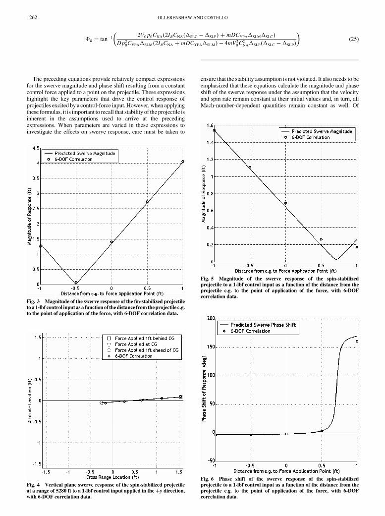
The preceding equations provide relatively compact expressionsfor the swerve magnitude and phase shift resulting from a constantcontrol force applied to a point on the projectile. These expressionshighlight the key parameters that drive the control response ofprojectiles excited by a control-force input. However, when applyingthese formulas, it is important to recall that stability of the projectile isinherent in the assumptions used to arrive at the precedingexpressions. When parameters are varied in these expressions toinvestigate the effects on swerve response, care must be taken to
ensure that the stability assumption is not violated. It also needs to beemphasized that these equations calculate the magnitude and phaseshift of the swerve response under the assumption that the velocityand spin rate remain constant at their initial values and, in turn, allMach-number-dependent quantities remain constant as well. Of
Fig. 4 Vertical plane swerve response of the spin-stabilized projectile
at a range of 5280 ft to a 1-lbf control input applied in the�y direction,with 6-DOF correlation data.
Fig. 3 Magnitude of the swerve response of the fin-stabilized projectile
to a 1-lbf control input as a function of the distance from theprojectile c.g.
to the point of application of the force, with 6-DOF correlation data.
Fig. 6 Phase shift of the swerve response of the spin-stabilizedprojectile to a 1-lbf control input as a function of the distance from the
projectile c.g. to the point of application of the force, with 6-DOF
correlation data.
Fig. 5 Magnitude of the swerve response of the spin-stabilized
projectile to a 1-lbf control input as a function of the distance from theprojectile c.g. to the point of application of the force, with 6-DOF
correlation data.
1262 OLLERENSHAW AND COSTELLO

course, this assumption becomes increasingly inaccurate as theprojectile proceeds downrange and must be periodically updated forlong-range trajectories.
III. Correlation to the Full Six-Degree-of-FreedomModel
To demonstrate the accuracy of the simplified swerve equations, atypical 120-mm fin-stabilized projectile and a typical 155-mm spin-stabilized projectile were evaluated. For both projectiles, the resultsobtained using Eqs. (23) and (25) were compared with results from afixed-step, fourth-order Runge–Kutta numerical integration of thefull 6-DOF equations of motion. The swerve response was evaluatedat a range of 5280 ft in the absence of gravity and atmospheric windsand with no initial yaw or pitch angles. In both cases, a 1-lbf controlinput was applied in the positive y direction. The control-forcemoment arm�SLC in Eqs. (23) and (25) was varied from 1 ft behindthe projectile center of mass to 1 ft in front of the projectile center ofmass. The 6-DOF swerve responsewas evaluated for both projectileswith control-forcemoment arms of�SLC ��1:0,�0:5, 0.0, 0.5, and1.0 ft.
Table 1 summarizes the initial conditions and the resultantaerodynamic coefficients, along with the relevant physicalparameters, for both projectiles, as used in Eqs. (23) and (25).
Figure 2 shows the swerve response of the fin-stabilized projectilein the vertical target plane at a downrange location of x� 5280 ft,with five 6-DOF data points included to demonstrate correlation. Itshould be noted that the positive z direction points downward, in thenegative altitude direction. Figure 3 shows the magnitude of theresponse as a function of control-force application point, along with6-DOF correlation data for the fin-stabilized projectile. Note that themagnitude of the response is dependent only upon the magnitude ofthe control input, not its direction. The phase shift, which is simply0 degwhen the force is applied in front of the COP and 180 degwhenit is applied behind the COP, is not shown. The phase shift of theresponse does not vary with the magnitude of the input and is alsoindependent of the direction of the input force.
Figure 4 shows the swerve response of the spin-stabilizedprojectile in the vertical target plane at a downrange location ofx� 5280 ft, with five 6-DOF data points included to demonstratecorrelation. Figures 5 and 6 show the magnitude and phase shift ofthe response along with 6-DOF correlation data for the spin-stabilized projectile.
Fig. 7 Summary of the projectile response to a control input in the positive y direction in both a fin-stabilized and a spin-stabilized projectile. Magnus
moments, which act 90 deg out of phase with the angle of attack in spin-stabilized projectiles, are not shown.
OLLERENSHAW AND COSTELLO 1263

For both the fin-stabilized and spin-stabilized projectiles studiedhere, the response as predicted by the simplified swerve equations isshown to correlate very well with that predicted by the full 6-DOFsimulation at this relatively short range. Though only a very smallfraction of the total terms comprising the full linear theory swerveexpressions are preserved in the simplified version, it is clear thatthose terms providing the dominant effect on the swerve responsehave been retained.
IV. Effects of Individual Parameters
Figures 2–6 clearly show that the point of application of thecontrol force has a very large effect on both the direction and themagnitude of the swerve response. Further, they demonstrate that theeffects are drastically different for fin- and spin-stabilized projectiles.The simplified swerve expressions provide insight into the reasonsfor this behavior. In the swerve-response magnitude and phaseexpressions given as Eqs. (23) and (25), the term expressing thedistance from the center-of-pressure location to the point ofapplication of the control force (�SLC ��SLP) shows up repeatedly.The practical result is that if the control force is applied at the centerof pressure,�SLC ��SLP becomes zero and the response magnitudeis at a minimum. In the case of a fin-stabilized projectile, which hasvery low spin rates and negligibly small Magnus effects as a result,the magnitude of the response goes to zero when the control force isapplied at the center of pressure.
The direction of the response is also driven by the center-of-pressure location relative to the projectile mass center. A typical fin-stabilized projectile will have a center-of-pressure location behindthe projectile center of mass. A control force applied in front of thecenter of pressure leads to a response largely in phase with thedirection of the control force. Conversely, when the control force isapplied behind the center of pressure, the response is nearly 180 degout of phase with the direction of the control force.
A spin-stabilized projectile, which typically has its center ofpressure located in front of the center of mass, displays the oppositebehavior. Additionally, the Magnus moment causes a relativelysmall response that is 90 deg out of phase with the direction of theapplied control force.
The physical explanation for this behavior is relativelystraightforward. Application of a control force away from the centerof gravity creates a nonzero angle of attack in the projectile. Thenormal force results directly from the angle of attack, and in a stableprojectile, it will create a moment equal and opposite to the momentcaused by the control input after the initial oscillatory epicyclicdynamics decay, creating a zero net moment on the body. Thedirection of the response will be driven primarily by the sum of thesetwo forces.When the control force is applied at the center of pressure,the normal force will be equal and opposite to the control force andthe response will be driven solely by the Magnus effect, which has anonnegligible effect only in spin-stabilized projectiles. Figure 7graphically summarizes the effects of a control force in the positive ydirection applied at varying points on the projectile body.
To demonstrate the relatively small contribution of the Magnusmoment in a spin-stabilized projectile, the swerve magnitude andphase shift of the spin-stabilized projectile were examined with theMagnus force coefficient equal to the nominal value (�0:96), half thenominal value (�0:48), and zero.
Themagnitude of the response is largely unaffected by reducing orremoving the Magnus moment, with the exception being when thecontrol force is applied near the projectile center of pressure. Whenthat is the case, the sum of the normal force and control force nearszero and the Magnus moment becomes the dominant factor in theresponse magnitude. When the Magnus moment is neglectedentirely, the magnitude of the response of the spin-stabilizedprojectile becomes zerowhen the control force is applied at the centerof pressure, as is the case in a fin-stabilized projectile.
The effect of the Magnus moment becomes more apparent whenexamining the phase response of the spin-stabilized projectile withvaried Magnus force coefficients, as shown in Fig. 8. The Magnusmoment acts 90 deg out of phase with the angle of attack of the
projectile. As the Magnus force coefficient is reduced, the portion ofthe response that is orthogonal to the control input diminishes. Withno Magnus moment present, the response is almost completely inphase with a force applied behind the center of pressure and is nearly180 deg out of phase for a force applied in front of the center ofpressure.
V. Conclusions
Relatively simple, closed-form formulas for the magnitude andphase angle of a projectile excited by a control force in terms offundamental projectile flight mechanic parameters were created. Theswerve-response formulas are remarkably accurate given the litanyof simplifications and the resulting compact form of the results.These formulas clearly explain the control response differencesbetween fin- and spin-stabilized projectiles, including the key rolethat the center of pressure plays in control-force response. It is shownthat fin-stabilized projectiles respond in phase to control-force inputsforward of the center of pressure whereas spin-stabilized projectilesrespond out of phase to control-force inputs forward of the center ofpressure. The simple formulas reported here are expected to be usefulto smart-weapon designers in bringing to light basic parameters thatdrive swerve response from different control mechanisms.
References
[1] Harkins, T., and Brown, T., “Using Active Damping as a Precision-Enhancing Technology for 2.75-Inch Rockets,” U. S. Army ResearchLab., ARL-TR-1772, Aberdeen Proving Ground, MD, 1999.
[2] Jitpraphai, T., and Costello, M., “Dispersion Reduction of a Direct FireRocket Using Lateral Pulse Jets,” Journal of Spacecraft and Rockets,Vol. 38, No. 6, 2001, pp. 929–936.
[3] Amitay, M., Smith, D., Kibens, V., Parekh, D., and Glezer, A.,“Aerodynamic Flow Control over an Unconventional AirfoilUsing Synthetic Jet Actuators,” AIAA Journal, Vol. 39, No. 3, 2001,pp. 361–370.
[4] Harkins, T., and Davis, B., “Drag-Brake Deployment Method andApparatus for Range Error Correction of Spinning, Gun-LaunchedArtillery Projectiles,” U.S. Patent 6345785, issued 12 Feb. 2002.
[5] T. Hillstrom, T., and Osborne, P., “United Defense Course CorrectingFuze for the Precision Guidance Kit Program,” 49th Annual Fuze
Conference, National Defense Industrial Association, Arlington, VA,5–7 Apr. 2005, http://proceedings.ndia.org/5560/Wednesday/Sessio-n_III-A/Osborne.pdf.
[6] Massey, K., and Flick, A., “Mechanical and Jet Actuators for Guiding a
Fig. 8 Phase shift of the swerve response of the spin-stabilizedprojectile to a 1-lbf control input as a function of the distance from the
projectile c.g. to the point of application of the control force. Magnus
force coefficient is varied from its nominal value to zero.
1264 OLLERENSHAW AND COSTELLO
Small Caliber Subsonic Projectile,” 25thAIAAApplied AerodynamicsConference, Miami, FL, AIAA Paper 2007-3813, 25–28 June 2007.
[7] Massey, K., McMichael, J., Warnock, T., and Hay, F., “MechanicalActuators for Guidance of a Supersonic Projectile,” 23rd AIAAApplied Aerodynamics Conference, Toronto, Ontario, Canada, AIAAPaper 2005-4970, 6–9 June 2005.
[8] Costello, M., and Agarwalla, R., “Improved Dispersion of a FinStabilized Projectile Using a Passive Moveable Nose,” Journal of
Guidance, Control, and Dynamics, Vol 23, No. 5, 2000, pp 900–903;also Errata, Vol. 25, No. 2, 2002, pp. 414.
[9] Costello, M., “Extended Range of a Gun Launched Smart ProjectileUsing Controllable Canards,” Shock and Vibration, Vol 8, Nos. 3–4,2001, pp. 203–213.
[10] Costello,M., and Peterson, A., “Linear Theory of aDual Spin Projectilein Atmospheric Flight,” Journal of Guidance, Control, and Dynamics,Vol. 23, No. 5, 2000, pp. 789–797.
[11] Burchett, B., Peterson, A., and Costello, M., “Prediction of SwervingMotion of aDual-Spin Projectile with Lateral Pulse Jets inAtmosphericFlight,” Mathematical and Computer Modelling, Vol. 35, No. 7–8,2002, pp. 821–834.doi:10.1016/S0895-7177(02)00053-5
[12] Chandgadkar, S., Costello, M., Dano, B., Liburdy, J., and Pence, D.,“Performance of a Smart Direct Fire Projectile Using aRamAir ControlMechanism,” Journal ofDynamic Systems,Measurement, andControl,Vol. 124, No. 4, 2002, pp. 606–612.doi:10.1115/1.1514666
[13] Rogers, J., and Costello, M., “Control Authority of a ProjectileEquippedwith an Internal TranslatingMass,” 2007AIAAAtmosphericFlight Mechanics Conference, Hilton Head, SC, AIAA Paper 2007-6492, 2007.
[14] McCoy, R. L., “Six-Degrees-of-Freedom (6 DOF) andModified Point-Mass Trajectories,”Modern Exterior Ballistics: the Launch and Flight
Dynamics of Symmetric Projectiles, Schiffer Publishing, Atglen, PA,1999, pp. 187–212.
[15] Hainz, L., and Costello, M., “Modified Projectile LinearTheory for Rapid Trajectory Prediction,” Journal of
Guidance, Control, and Dynamics, Vol. 28, No. 5, 2005, pp. 1006–1014.
[16] McCoy, R. L., “Aerodynamic Forces and Moments Acting onProjectiles,” Modern Exterior Ballistics: the Launch and Flight
Dynamics of Symmetric Projectiles, Schiffer Publishing, Atglen, PA,1999, pp. 32–40.
OLLERENSHAW AND COSTELLO 1265