SIMOTICS M-1PH8 Induction motor - Siemens · PDF fileInduction motor SIMOTICS M-1PH8 1PH8 ......
160
Induction motor SIMOTICS M-1PH8 Type 1PH818., 1PH822. forced ventilated II 3D Ex tc IIIB T150°C Dc Operating Instructions / Installation Instructions 11/2012
Transcript of SIMOTICS M-1PH8 Induction motor - Siemens · PDF fileInduction motor SIMOTICS M-1PH8 1PH8 ......

Induction motorSIMOTICS M-1PH8 Type 1PH818., 1PH822. forced ventilated
II 3D Ex tc IIIB T150°C Dc Operating Instructions / Installation Instructions 11/2012

30.11.2012 17:35V11.02

Induction motor
SIMOTICS M-1PH81PH8
Operating InstructionsInstallation Instructions
For employment in zone 22 (IEC/EN 60079-10-2) II 3D Ex tc IIIB T150°C Dc
Edition 11/2012
Introduction 1
Safety information 2
Description 3
Preparations for use 4
Mounting 5
Electrical connection 6
Commissioning 7
Operation 8
Maintenance 9
Spare parts 10
Disposal 11
Service and Support A
Quality documents B
Additional documents C

Legal informationWarning notice system
This manual contains notices you have to observe in order to ensure your personal safety, as well as to prevent damage to property. The notices referring to your personal safety are highlighted in the manual by a safety alert symbol, notices referring only to property damage have no safety alert symbol. These notices shown below are graded according to the degree of danger.
DANGER
indicates that death or severe personal injury will result if proper precautions are not taken.
WARNING
indicates that death or severe personal injury may result if proper precautions are not taken.
CAUTION
indicates that minor personal injury can result if proper precautions are not taken.
NOTICEindicates that property damage can result if proper precautions are not taken.If more than one degree of danger is present, the warning notice representing the highest degree of danger will be used. A notice warning of injury to persons with a safety alert symbol may also include a warning relating to property damage.
Qualified PersonnelThe product/system described in this documentation may be operated only by personnel qualified for the specific task in accordance with the relevant documentation, in particular its warning notices and safety instructions. Qualified personnel are those who, based on their training and experience, are capable of identifying risks and avoiding potential hazards when working with these products/systems.
Proper use of Siemens productsNote the following:
WARNING
Siemens products may only be used for the applications described in the catalog and in the relevant technical documentation. If products and components from other manufacturers are used, these must be recommended or approved by Siemens. Proper transport, storage, installation, assembly, commissioning, operation and maintenance are required to ensure that the products operate safely and without any problems. The permissible ambient conditions must be complied with. The information in the relevant documentation must be observed.
TrademarksAll names identified by ® are registered trademarks of Siemens AG. The remaining trademarks in this publication may be trademarks whose use by third parties for their own purposes could violate the rights of the owner.
Disclaimer of LiabilityWe have reviewed the contents of this publication to ensure consistency with the hardware and software described. Since variance cannot be precluded entirely, we cannot guarantee full consistency. However, the information in this publication is reviewed regularly and any necessary corrections are included in subsequent editions.
Siemens AGIndustry SectorPostfach 48 4890026 NÜRNBERGGERMANY
Order number: A5E03986435A ABⓅ 11/2012 Technical data subject to change
Copyright © Siemens AG 2012.All rights reserved

Table of contents
1 Introduction.................................................................................................................................................11 1.1 Content........................................................................................................................................11
2 Safety information.......................................................................................................................................13 2.1 Information for the nominated person in control of the electrical installation...............................13 2.2 The five safety rules:...................................................................................................................13 2.3 Qualified personnel......................................................................................................................14 2.4 Safe handling...............................................................................................................................14 2.5 For use in hazardous areas in Zone 22.......................................................................................16 2.6 Electrostatic sensitive devices.....................................................................................................17 2.7 Electromagnetic compatibility......................................................................................................18 2.8 Interference immunity..................................................................................................................18 2.9 Interference voltages when operating the converter...................................................................18 2.10 Electromagnetic fields when operating electrical power engineering installations......................19
3 Description..................................................................................................................................................21
4 Preparations for use...................................................................................................................................29 4.1 Safety-related aspects to consider when configuring the plant...................................................29 4.2 Ensuring cooling..........................................................................................................................29 4.3 Cooling air quality........................................................................................................................31 4.4 Interlock circuit for the external fan..............................................................................................31 4.5 Thermal motor protection............................................................................................................31 4.6 Overheating during periodic duty.................................................................................................32 4.7 Noise emissions..........................................................................................................................32 4.8 Rotational speed limit values.......................................................................................................32 4.9 System-inherent frequencies.......................................................................................................33 4.10 Torsional loading of the shaft assembly due to faults in the electrical supply.............................33 4.11 Transport and storage.................................................................................................................33 4.11.1 Checking the delivery..................................................................................................................34 4.11.2 Requirements for safe lifting and transporting.............................................................................34 4.11.3 Lifting and transporting................................................................................................................35 4.11.4 Transporting a force-ventilated motor that has already been in operation..................................37 4.11.5 Transporting the machine set......................................................................................................37 4.11.6 Storage........................................................................................................................................38 4.11.7 Attaching the rotor shipping brace prior to storage......................................................................39 4.11.8 Long-term storage.......................................................................................................................40
SIMOTICS M-1PH8Operating Instructions 11/2012 A5E03986435A AB 5

4.11.9 Protection against corrosion........................................................................................................41 4.12 Converter operation.....................................................................................................................41 4.12.1 Connection to a converter...........................................................................................................41 4.12.2 Insulated bearings for converter operation..................................................................................42 4.12.3 Operation with insulated coupling................................................................................................43
5 Mounting.....................................................................................................................................................45 5.1 Insulation resistance and polarization index................................................................................45 5.2 Testing the insulation resistance and polarization index.............................................................46 5.3 Preconditions for correct alignment and secure attachment ......................................................48 5.4 Vibration severity.........................................................................................................................49 5.5 Aligning the machine...................................................................................................................50 5.6 Securing the machine..................................................................................................................51 5.7 Tightening torques for screw and bolt connections.....................................................................52 5.8 Mounting the output elements.....................................................................................................53
6 Electrical connection...................................................................................................................................57 6.1 Safety instructions relating to the electrical connection...............................................................57 6.2 Preparation..................................................................................................................................58 6.2.1 Selecting cables..........................................................................................................................58 6.2.2 Connecting the grounding conductor...........................................................................................58 6.3 Connecting..................................................................................................................................59 6.3.1 Circuit diagram............................................................................................................................59 6.3.2 Terminal designation...................................................................................................................59 6.3.3 Laying cables...............................................................................................................................59 6.3.4 Electrical connection data............................................................................................................60 6.3.5 Connection with cable lugs..........................................................................................................61 6.3.6 Connecting aluminum conductors...............................................................................................63 6.3.7 Completing connection work.......................................................................................................64 6.3.8 Internal equipotential bonding.....................................................................................................64 6.4 Auxiliary circuits...........................................................................................................................65 6.4.1 Selecting cables..........................................................................................................................65 6.4.2 Connecting the auxiliary circuits..................................................................................................65 6.4.3 Intrinsically safe circuits for sensors or probes............................................................................65 6.4.4 Connecting an external fan..........................................................................................................66 6.4.5 Connecting the speed encoder....................................................................................................68 6.4.6 Attach a protective tube for the signal connector........................................................................70 6.4.7 Connecting the temperature sensor............................................................................................71 6.4.8 Connection to a converter...........................................................................................................71 6.4.9 Converter operation on a grounded network...............................................................................72 6.4.10 Connect metal shield in the terminal box ....................................................................................73
7 Commissioning...........................................................................................................................................75 7.1 Insulation resistance and polarization index................................................................................75 7.2 Checks to be carried out prior to commissioning ........................................................................75 7.3 Switching on................................................................................................................................77
Table of contents
SIMOTICS M-1PH86 Operating Instructions 11/2012 A5E03986435A AB

7.4 Test run.......................................................................................................................................78
8 Operation....................................................................................................................................................79 8.1 Safety guidelines in operation.....................................................................................................79 8.2 Machine overheating caused by dust..........................................................................................80 8.3 Operation.....................................................................................................................................81 8.4 Switching-off force-ventilated motors..........................................................................................82 8.5 Switching on again after an emergency switching-off.................................................................82 8.6 Stoppages...................................................................................................................................82 8.6.1 Avoidance of damage to roller bearings during stoppages.........................................................83 8.6.2 Measurement of the insulation resistance after an extended stoppage......................................83 8.7 Decommissioning the machine....................................................................................................83 8.8 Re-commissioning the machine..................................................................................................84 8.9 Faults...........................................................................................................................................84 8.9.1 Inspections in the event of faults.................................................................................................84 8.9.2 Electrical faults at force-ventilated motors...................................................................................84 8.9.3 Mechanical faults.........................................................................................................................85 8.9.4 Roller bearing faults.....................................................................................................................86
9 Maintenance...............................................................................................................................................87 9.1 Qualified personnel......................................................................................................................87 9.2 Observe the operating instructions of the components...............................................................87 9.3 Inspection and maintenance........................................................................................................88 9.3.1 Inspections in the event of faults.................................................................................................90 9.3.2 Initial inspection...........................................................................................................................90 9.3.3 General inspection.......................................................................................................................91 9.3.4 Rolling-contact bearing inspection...............................................................................................91 9.3.5 Changing bearings when using permanently lubricated rolling-contact bearings.......................92 9.3.6 Maintenance................................................................................................................................92 9.3.6.1 Measuring the insulation resistance during the course of maintenance work.............................94 9.3.6.2 Maintenance intervals..................................................................................................................94 9.3.6.3 Rolling-contact bearings..............................................................................................................94 9.3.6.4 Lubrication...................................................................................................................................95 9.3.6.5 Cleaning the spent grease chamber............................................................................................99 9.3.6.6 Cleaning the cooling air passages.............................................................................................101 9.3.6.7 Maintaining terminal boxes........................................................................................................103 9.4 Repair........................................................................................................................................104 9.4.1 Prepare servicing work..............................................................................................................104 9.4.2 Explosion hazard during installation and disassembling of the external fan.............................105 9.4.3 Disassembling the machine.......................................................................................................106 9.4.4 Removing and installing the protecting ring...............................................................................107 9.4.5 Removing and mounting the bearing shields............................................................................108 9.4.6 Installing the machine................................................................................................................108 9.4.7 Removing the external fan.........................................................................................................109 9.4.8 Removing and mounting the speed encoder.............................................................................109 9.4.9 Touch up any damaged paintwork............................................................................................110
Table of contents
SIMOTICS M-1PH8Operating Instructions 11/2012 A5E03986435A AB 7

10 Spare parts...............................................................................................................................................111 10.1 Ordering data.............................................................................................................................111 10.2 Spare parts kits..........................................................................................................................111 10.3 Ordering spare parts via the Internet.........................................................................................112 10.4 Using commercially available spare parts.................................................................................112 10.5 Spare parts force-ventilated motor............................................................................................113 10.5.1 Force-ventilated motor, complete..............................................................................................113 10.5.2 External fan...............................................................................................................................114 10.5.3 Roller bearing cartridge DE with radial shaft sealing ring with regreasing................................115 10.5.4 Roller bearing cartridge DE, belt coupling.................................................................................116 10.5.5 Roller bearing cartridge DE, coupling output, with regreasing..................................................117 10.5.6 Roller bearing cartridge DE, coupling output, with permanent lubrication.................................118 10.5.7 Roller bearing cartridge NDE, with permanent lubrication.........................................................119 10.5.8 Roller bearing cartridge NDE, with regreasing (type 1PH818., 1PH822.).................................120 10.6 Terminal box..............................................................................................................................121 10.7 Speed encoder (type 1PH818., 1PH822.).................................................................................122
11 Disposal....................................................................................................................................................123 11.1 Introduction................................................................................................................................123 11.2 Preparing for disassembly.........................................................................................................123 11.3 Dismantling the machine...........................................................................................................123 11.4 Disposal of components............................................................................................................124
A Service and Support.................................................................................................................................125 A.1 Siemens Service Center............................................................................................................125
B Quality documents....................................................................................................................................127 B.1 EC Declaration of Conformity 2006/95/EC................................................................................129 B.2 EC Declaration of Conformity (Ex t)..........................................................................................131
C Additional documents...............................................................................................................................145 C.1 Operating instructions, external fan...........................................................................................146
Index.........................................................................................................................................................155
Tables
Table 3-1 Elements on the rating plate........................................................................................................22Table 3-2 Machine design ........................................................................................................................23Table 3-3 Motor version with type of explosion protection Ex t ..............................................................23Table 3-4 Roller bearing versions .............................................................................................................26Table 3-5 Minimum radial forces.................................................................................................................26Table 4-1 Pressure drop in motors with pipe connection ..........................................................................30Table 4-2 Tightening torque for rotor shipping brace ................................................................................36
Table of contents
SIMOTICS M-1PH88 Operating Instructions 11/2012 A5E03986435A AB
Table 5-1 Stator winding insulation resistance at 40° C..............................................................................47Table 5-2 Maximum permitted radial vibration severity...............................................................................49Table 5-3 Maximum permitted axial vibration severity.................................................................................49Table 5-4 Permissible deviations when aligning the motor..........................................................................51Table 5-5 Tightening torques for bolted connections with a tolerance of ±10%..........................................53Table 6-1 Terminal designations using the 1U1-1 as an example...............................................................59Table 6-2 Data for electrical connection......................................................................................................61Table 8-1 Electrical faults .........................................................................................................................85Table 8-2 Mechanical faults ......................................................................................................................85Table 8-3 Roller bearing faults ................................................................................................................86Table 9-1 Checks after installation or repair ...............................................................................................90Table 9-2 Maintenance measures...............................................................................................................94Table 9-3 Criteria for selecting roller bearing greases.................................................................................95Table 9-4 Roller bearing greases for vertical and horizontal types of construction ....................................96Table 9-5 Alternative greases with NLGI Class 2 for motors with a horizontal type of construction............96Table 9-6 Lubricating grease for the Performance version (Option L37).....................................................97Table 10-1 Motor, complete .......................................................................................................................113Table 10-2 Spare parts for external fan.......................................................................................................114Table 10-3 Spare parts for rolling-contact bearing bush drive end with mounted gearing, with regreasing 115Table 10-4 Spare parts for rolling-contact bearing bush drive end with belt coupling, with regreasing.......116Table 10-5 Spare parts for rolling-contact bearing bush drive end, with coupling output, with regreasing 117Table 10-6 Spare parts for rolling-contact bearing bush drive end, with coupling output, with permanent
lubrication .................................................................................................................................118Table 10-7 Spare parts for roller bearing cartridge, non-drive end, permanent lubrication ........................119Table 10-8 Spare part, roller bearing cartridge NDE, with regreasing (type 1PH818., 1PH822.) ..............120Table 10-9 Spare parts for terminal box .....................................................................................................121Table 10-10 Spare part, speed encoder (type 1PH818., 1PH822.)...............................................................122Table A-1 Service numbers........................................................................................................................125
Figures
Figure 3-1 Schematic layout of rating plate..................................................................................................22Figure 3-2 Ex plate on the machine (schematic representation)..................................................................24Figure 4-1 Air guidance from NDE to DE (schematic representation)..........................................................30Figure 4-2 Lifting the machine (schematic representation)...........................................................................35Figure 4-3 Rotor shipping brace...................................................................................................................36Figure 4-4 Schematic representation of a single drive..................................................................................42Figure 5-1 Max. permissible vibration velocity, taking into account the vibration displacement and vibration
acceleration.................................................................................................................................50Figure 5-2 Aligning the machine...................................................................................................................51
Table of contents
SIMOTICS M-1PH8Operating Instructions 11/2012 A5E03986435A AB 9

Figure 5-3 Balancing type on the drive-end side..........................................................................................53Figure 6-1 Detailed view: Connection point ① for ground conductor...........................................................58Figure 6-2 Connection in the external fan terminal box................................................................................67Figure 6-3 External fan terminal box ① (schematic representation)............................................................68Figure 6-4 Detailed view: Plug-in connection ...............................................................................................69Figure 6-5 Sensor Module ① mounted on the terminal box........................................................................69Figure 6-6 Slide the protective tube to remove the signal connector over the signal connector..................70Figure 6-7 Screw the protective tube to remove the connector to the end position......................................70Figure 9-1 Flat grease nipples ① and ② (schematic representation for types 1PH818. and 1PH822.).....99Figure 9-2 Fitting the protecting ring...........................................................................................................108Figure 10-1 Schematic representation of the motor, complete.....................................................................113Figure 10-2 Spare parts for external fan (type 1PH818., 1PH822.) ............................................................114Figure 10-3 Rolling-contact bearing bush drive end with mounted gearing, with regreasing.......................115Figure 10-4 Rolling-contact bearing bush drive end with belt coupling, with regreasing..............................116Figure 10-5 Rolling-contact bearing bush drive end, with coupling output, with regreasing.........................117Figure 10-6 Rolling-contact bearing bush drive end, with coupling output, with permanent lubrication.......118Figure 10-7 Roller bearing cartridge, non-drive end, permanent lubrication ................................................119Figure 10-8 Roller bearing cartridge NDE, with regreasing (type 1PH818., 1PH822.).................................120Figure 10-9 Terminal box..............................................................................................................................121Figure 10-10 Speed encoder..........................................................................................................................122
Table of contents
SIMOTICS M-1PH810 Operating Instructions 11/2012 A5E03986435A AB

Introduction 11.1 Content
These operating instructions are valid for 1PH8 induction motors in shaft heights 180 ... 225 in the force-ventilated version.
● 1PH818.1 and 1PH818.3
● 1PH822.1 and 1PH822.3
The serial number of the motor can be found on the rating plate.
These instructions describe the machine and explain how to handle it, from initial delivery to final disposal of the equipment. Keep these instructions for later use.
Read these operating instructions before you handle the machine and follow the instructions. to become familiar with its design and operating principles and thus ensure safe, problem-free machine operation and long service life.
If you have suggestions for improving the document, please contact our Service Center (Page 125).
Text format featuresThe warning notice system is explained on the rear of the inside front. Always follow the safety instructions and notices in these instructions.
In addition to the safety-related warning notices which you must read, you will find the text in these instructions is formatted in the following way:
1. Handling instructions are always formatted as a numbered list. Always perform the steps in the order given.
● Lists are formatted as bulleted lists.
– Lists on the second level are hyphenated.
Note
A Note is an important item of information about the product, handling of the product or the relevant section of the document. Notes provide you with help or further suggestions/ideas.
SIMOTICS M-1PH8Operating Instructions 11/2012 A5E03986435A AB 11

Introduction1.1 Content
SIMOTICS M-1PH812 Operating Instructions 11/2012 A5E03986435A AB
Safety information 22.1 Information for the nominated person in control of the electrical
installationThis electric machine has been designed and built in accordance with the specifications contained in Directive 2006/95/EC ("Low-Voltage Directive") and is intended for use in industrial plants. Please observe the country-specific regulations when using the electric machine outside the European Community.
Follow the local and industry-specific safety and setup regulations.
The persons responsible for the plant must ensure the following:
● Planning and configuration work and all work carried out on and with the machine is only to be done by qualified personnel.
● The operating instructions must always be available for all work.
● The technical data as well as the specifications relating to the permissible installation, connection, ambient and operating conditions are taken into account at all times.
● The specific setup and safety regulations as well as regulations on the use of personal protective equipment are observed.
Note
Use the services and support provided by the appropriate Service Center (Page 125) for planning, installation, commissioning, and servicing work.
In the individual chapters of this document, you will find safety instructions that must be obeyed absolutely, for your own safety, to protect other people and to avoid damage to property.
Observe the following safety instructions for all activities on and with the machine.
2.2 The five safety rules:For your personal safety and to prevent material damage when working on the machine, always observe the safety instructions and the following five safety rules, according to EN 50110‑1 "Working in a voltage-free state". Apply the five safety rules in the order stated before starting work at the machine.
Five safety rules 1. Disconnect the system.
Disconnect the auxiliary circuits, for example anti-condensation heating
2. Prevent reconnection.
3. Make sure that the equipment is at zero voltage
SIMOTICS M-1PH8Operating Instructions 11/2012 A5E03986435A AB 13

4. Ground and short-circuit
5. Cover or isolate nearby components that are still live.
To energize the system, apply the measures in reverse order.
2.3 Qualified personnelAll work at the machine must be carried out by qualified personnel only. For the purpose of this documentation, qualified personnel is taken to mean people who fulfill the following requirements:
● Through appropriate training and experience, they are able to recognize and avoid risks and potential dangers in their particular field of activity.
● They have been instructed to carry out work on the machine by the appropriate person responsible.
2.4 Safe handlingWorkplace safety depends on the attentiveness, care, and common sense of the personnel who install, operate, and maintain the machine. In addition to the safety measures cited, as a matter of principle, the use of caution is necessary when you are near the machine. Always pay attention to your safety.
Also observe the following to prevent accidents:
● General safety regulations applicable in the country where the machine is deployed.
● Manufacturer-specific and application-specific regulations
● Special agreements made with the operator
● Separate safety instructions supplied with the machine
● Safety symbols and instructions on the machine and its packaging
WARNING
Live parts
Electric machines contain live parts.
Fatal or severe injuries and substantial material damage can occur if the covers are removed or if the machine is not handled, operated, or maintained properly.● Always observe the "five safety rules (Page 13)" when carrying out any work on the
machine.● Only remove the covers using the methods described by these operating instructions.● Operate the machine properly.● Regularly and correctly maintain the machine.
Safety information2.4 Safe handling
SIMOTICS M-1PH814 Operating Instructions 11/2012 A5E03986435A AB

WARNING
Rotating components
Electric machines contain dangerous rotating parts.
Fatal or severe injuries and substantial material damage can occur if the covers are removed or if the machine is not handled, operated, or maintained properly.● Only remove the covers using the methods described by these operating instructions.● Operate the machine properly.● Perform regular maintenance on the machine.● Secure free-standing shaft ends.
WARNING
Hot surfaces
Electric machines have hot surfaces. Do not touch these surfaces. They could cause burns.● Allow the machine to cool before starting work on the machine.● Only remove the covers using the methods described by these operating instructions.● Operate the machine properly.
CAUTION
Hazardous substances
Chemical substances required for the setup, operation and maintenance of machines can present a health risk.
Poisoning, skin damage, cauterization of the respiratory tract, and other health damage may result.● Read the information in these operating instructions and the product information supplied
by the manufacturer.● Observe the relevant safety regulations and wear the personal protective equipment
specified.
CAUTION
Flammable substances
Chemical substances required for the setup, operation and maintenance of machines may be flammable.
Burns and other damage to health and material may result.● Read the information in these operating instructions and the product information supplied
by the manufacturer.● Observe the relevant safety regulations and wear the personal protective equipment
specified.
Safety information2.4 Safe handling
SIMOTICS M-1PH8Operating Instructions 11/2012 A5E03986435A AB 15

WARNING
Noise emissions
During operation, the machine's noise emission levels can exceed those permitted at the work place. which can cause hearing damage.
Take steps to reduce noise, such as introducing covers and protective insulation or adopting hearing protection measures, so that the machine can be operated safely within your system.
2.5 For use in hazardous areas in Zone 22Electrical systems in hazardous areas must be assembled, installed, and operated by the responsible persons in accordance with the applicable rules and regulations.
Note
The basic requirements relating to electrical systems and their operation in hazardous areas are described, for instance, in the 94/9/EG and 1999/92/EG directives as well as in the IEC / EN 60079-14 standard.
Ignition hazards The assessment of operating risks and local operating conditions and the necessary monitoring methods must be clarified and made binding by the system operator, coordinated with the responsible supervisory authority. It is mandatory that the necessary measures are complied with. The machine manufacturer cannot offer any generally applicable recommendations in this case. Please observe the information in these operating instructions.
Note
The basic requirements relating to the assessment of ignition hazards arising from electrical systems and their operation in hazardous areas are given, for instance, in the 94/9/EG and 1999/92/EG directives as well as in the IEC / EN 60079 series of standards.
Safety information2.5 For use in hazardous areas in Zone 22
SIMOTICS M-1PH816 Operating Instructions 11/2012 A5E03986435A AB

2.6 Electrostatic sensitive devices
ESD protective measures
NOTICE
Electrostatic discharge
Electronic modules contain components that can be destroyed by electrostatic discharge.
These modules can be easily destroyed by improper handling.
To protect your equipment against damage, follow the instructions given below.● Never touch electronic modules unless absolutely necessary in the course of maintenance
and repair procedures. ● If the modules have to be touched, the body of the person concerned must be
electrostatically discharged immediately beforehand and be grounded.● Electronic modules should not be brought into contact with electrically insulating materials
such as plastic film, plastic parts, insulating table supports or clothing made of synthetic fibers.
● Always place electrostatic sensitive devices on conductive bases.● Always pack, store and transport electronic modules or components in conductive
packaging, e.g. metallized plastic or metal containers, conductive foam material or domestic aluminum foil.
The necessary ESD protective measures for electrostatic sensitive devices are illustrated once again in the following drawings:
d
f f f f
b
e
a a ac c c
e
b
f
d d
(1) (2) (3)
e
a
(1) Sitting (2) Standing (3) Standing/sittinga = conductive floor surface b = ESD table c = ESD shoesd = ESD overall e = ESD wristband f = cabinet ground connection
Safety information2.6 Electrostatic sensitive devices
SIMOTICS M-1PH8Operating Instructions 11/2012 A5E03986435A AB 17

WARNING
Risk of explosion due to electrostatic discharge
Electrostatic discharge poses a potential ignition source. In an explosive atmosphere, there is a risk of an explosion. This can result in death, serious injury or material damage.
Please comply with ESD protective measures.
2.7 Electromagnetic compatibilityThis machine is designed in accordance with IEC/EN 60034 and, when used as prescribed, it satisfies the requirements of European Directive 2004/108/EG on electromagnetic compatibility.
2.8 Interference immunityThe machine fulfills the requirements regarding interference immunity in accordance with IEC/EN 61000‑6‑2.
When using machines with integrated sensors (e.g. PT100, PTC thermistors), the manufacturers of the complete systems must ensure sufficient interference immunity by selecting suitable sensor signal leads and evaluation units.
2.9 Interference voltages when operating the converter
WARNING
Interference voltages when operating the converter
When a converter is in operation, the emitted interference varies in strength depending on the converter (manufacturer, type, interference suppression measures undertaken). On motors with integrated sensors (e.g. PTC thermistors), interference voltages caused by the converter may occur on the sensor lead. This can cause faults which can result in eventual or immediate death, serious injury or material damage.
In order to avoid exceeding the limit values set for the drive system (motor and converter) in IEC/EN 61000-6-3, the EMC information provided by the converter manufacturer must be observed. You must put appropriate EMC measures in place.
Safety information2.9 Interference voltages when operating the converter
SIMOTICS M-1PH818 Operating Instructions 11/2012 A5E03986435A AB

2.10 Electromagnetic fields when operating electrical power engineering installations
WARNING
Interference on electronic devices through electromagnetic fields
Electromagnetic fields are generated during operation of electrical power engineering installations. Electromagnetic fields can interfere with electronic devices, resulting in malfunctioning of those devices. The operation of heart pacemakers can be impaired, potentially leading to damage to a person's health or even death. It is therefore forbidden for persons with heart pacemakers to come into the vicinity of the machine. Data may be lost from magnetic or electronic data media.
As the operator of the installation, you must take the following measures:● Ensure that the personnel working on the plant are adequately protected from any harm
by making appropriate arrangements, such as erecting identifying markings, safety barriers and warning signs and giving safety talks.
● Observe the nationally applicable health and safety regulations.● Do not carry any magnetic or electronic data media with you.
Safety information2.10 Electromagnetic fields when operating electrical power engineering installations
SIMOTICS M-1PH8Operating Instructions 11/2012 A5E03986435A AB 19

Safety information2.10 Electromagnetic fields when operating electrical power engineering installations
SIMOTICS M-1PH820 Operating Instructions 11/2012 A5E03986435A AB

Description 3
Application range The motors of the 1PH818., 1PH822., series are used as industrial drives. They have been designed to address a wide range of drive applications exclusively fed from converters.
They are characterized by their high power density, ruggedness, long lifetime, and overall reliability.
Type of protection Ex tcThis machine has been designed in accordance with the "constructional safety" (Ex tc) type of protection in line with IEC / EN‑60079‑0 and IEC / EN 60079‑31 . It may, therefore, be operated in hazardous areas in the presence of non-conductive, combustible dust in Zone 22 in accordance with IEC / EN 60079‑10‑2 .
WARNING
Risk of explosion
This machine is not designed for use in the following areas: ● Explosive gas atmospheres.● Areas in which an explosion hazard exists due to hybrid mixtures.● Areas with dust of explosive materials.● Dust explosion protection areas with conducting dusts● Areas with pyrophoric materials.
An explosion can occur if the machine is operated in these areas. This can result in death, serious injury or material damage.
Never operate this machine in the above mentioned areas.
Rating plateThe rating plate shows the identification data and the most important technical data. The data on the rating plate and the contractual agreements define the limits of proper usage.
SIMOTICS M-1PH8Operating Instructions 11/2012 A5E03986435A AB 21
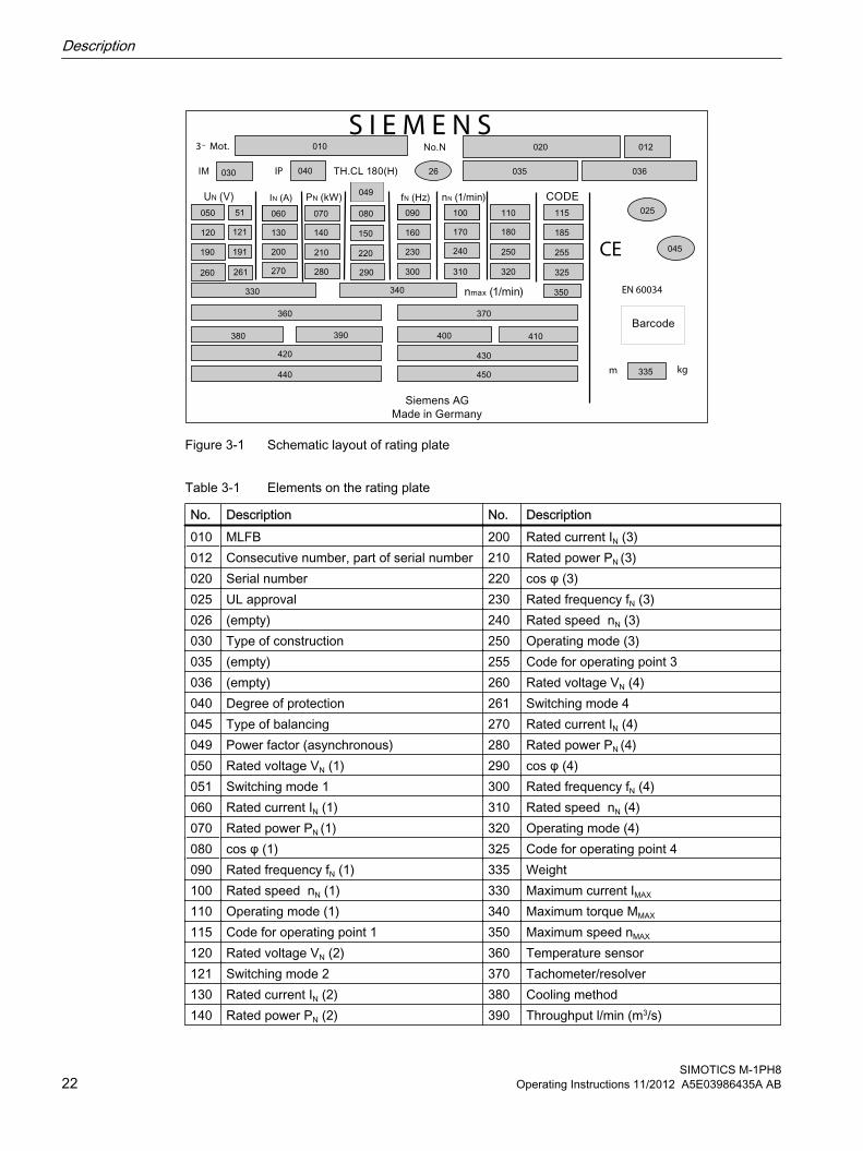
Figure 3-1 Schematic layout of rating plate
Table 3-1 Elements on the rating plate
No. Description No. Description010 MLFB 200 Rated current IN (3)012 Consecutive number, part of serial number 210 Rated power PN (3)020 Serial number 220 cos φ (3)025 UL approval 230 Rated frequency fN (3)026 (empty) 240 Rated speed nN (3)030 Type of construction 250 Operating mode (3)035 (empty) 255 Code for operating point 3036 (empty) 260 Rated voltage VN (4)040 Degree of protection 261 Switching mode 4045 Type of balancing 270 Rated current IN (4)049 Power factor (asynchronous) 280 Rated power PN (4)050 Rated voltage VN (1) 290 cos φ (4)051 Switching mode 1 300 Rated frequency fN (4)060 Rated current IN (1) 310 Rated speed nN (4)070 Rated power PN (1) 320 Operating mode (4)080 cos φ (1) 325 Code for operating point 4090 Rated frequency fN (1) 335 Weight100 Rated speed nN (1) 330 Maximum current IMAX
110 Operating mode (1) 340 Maximum torque MMAX
115 Code for operating point 1 350 Maximum speed nMAX
120 Rated voltage VN (2) 360 Temperature sensor121 Switching mode 2 370 Tachometer/resolver130 Rated current IN (2) 380 Cooling method140 Rated power PN (2) 390 Throughput l/min (m3/s)
Description
SIMOTICS M-1PH822 Operating Instructions 11/2012 A5E03986435A AB

No. Description No. Description150 cos φ (2) 400 System pressure160 Rated frequency fN (2) 410 Maximum coolant temperature170 Rated speed nN (2) 420 Options (I)180 Operating mode (2) 430 Options (II)185 Code for operating point 2 440 Optional customer information190 Rated voltage VN (3) 450 Anti-condensation heater / place holder191 Switching mode 3
Rotor This machine is an induction motor for low voltage with squirrel-cage induction motor and integrated cooling circuit.
Machine design The regulations and standards used as basis for designing and testing this machine are stamped on the rating plate. The machine design basically complies with the subsequent standards: Please refer to the EC Declaration of Conformity for the versions of the harmonized standards referenced.
Table 3-2 Machine design
Feature StandardDimensions and operation characteristics IEC / EN 60034-1Degree of protection IEC / EN 60034-5Cooling IEC / EN 60034-6Type of construction IEC / EN 60034-7Terminal markings and direction of rotation IEC/EN 60034-8Noise emission IEC / EN 60034-9Mechanical vibrations IEC / EN 60034-14IEC‑standard voltages IEC/DIN IEC 60038Vibration limit values DIN ISO 10816-3
The following standards additionally apply for explosion-proof motors:
Table 3-3 Motor version with type of explosion protection Ex t
Feature StandardType of protection Ex t ① IEC / EN 60079-0
IEC / EN 60079-31① Optional (depending on order)
Description
SIMOTICS M-1PH8Operating Instructions 11/2012 A5E03986435A AB 23

Figure 3-2 Ex plate on the machine (schematic representation)
Drive The motor speed is controlled using a converter.
NOTICE
Destruction of the machine when operated directly from the line supply
The machine will be destroyed if it is directly connected to the line supply. Only operate the machine using a converter.
Types of construction The motor is supplied with two attached lifting eyes. The type construction can be found on the rating plate.
Vertical type of constructionFor IM V5 and IM V15 types of construction with "shaft extension pointing downward", the motor is equipped with two additional Vario eye bolts. The Vario eyebolts are in the terminal box.
NOTICE
Protection against falling parts
For vertical types of construction, protect the air intake or discharge against falling parts, e.g. by attaching a canopy. Otherwise the machine could be damaged.
Description
SIMOTICS M-1PH824 Operating Instructions 11/2012 A5E03986435A AB

Cooling with external fanThe machine has cooling method IC 416 in accordance with IEC / EN 60034-6. The separately driven fan unit and the terminal box can be mounted in a different position depending on the order.
WARNING
Operating instructions, external fan
Improper use of the external fan can result in death, serious injury, and material damage.
Observe and follow the operating instructions of the external fan.
NOTICE
Minimum clearance for mounted accessories
If the required cooling air flow cannot be maintained, then the machine can overheat. Material damage can result.
Maintain a minimum clearance of 300 mm for customer-supplied mounted accessories at the air intake opening and at the air discharge openings to ensure the required cooling air flow.
EC external fan from the Ziehl-Abegg companyFor air-cooled 1PH8. motors, the EC external fans from the Ziehl-Abegg company are installed. This are especially designed fan units for this motor series, with a permanently set operating speed. The external fan is suitable for use in hazardous areas of Zone 22.
Terminals GND; 10V; D1; I1; A1 and A2 must not be connected and are therefore equipped with insulators.
NOTICE
The use in IT systems is not permitted.
NOTICE
The external fan may not be cleaned with a water jet. This results in material damage.
Degree of protectionThe machine is available with degree of protection IP55.
Description
SIMOTICS M-1PH8Operating Instructions 11/2012 A5E03986435A AB 25

Supplementary devices A KTY 84 temperature sensor is installed (Page 71) in the stator winding for winding control.
Depending on the order options, various supplementary devices such as encoder systems can be installed or mounted, which are suitable for use in Zone 22.
Ambient conditionsThe standard machines are not suitable for use in corrosive atmospheres, atmospheres with a high salt content, or outdoor applications.
Roller bearingsThe machines are equipped with different types of roller bearings depending on the version and the operating conditions described in the order. If the machine is equipped with a regreasing system, you will find the relevant data on the machine's lubricant plate.
The following standard roller bearing versions are available:
Table 3-4 Roller bearing versions
Design BearingsStandard design Drive end deep-groove ball bearing as spring-loaded floating
bearingNon-drive end deep-groove ball bearing as fixed bearing
Version for increased radial forces Drive end cylindrical-roller bearing as floating bearingNon-drive end deep-groove ball bearing as fixed bearing
NOTICE
Maintain the minimum radial forces
Operating cylindrical roller bearings without a load can damage them. Maintain the minimum radial forces specified when using cylindrical-roller bearings.
Table 3-5 Minimum radial forces
Type Minimum radial force1PH818. 4 kN1PH822. 5 kN1PH828. 9 kN
Description
SIMOTICS M-1PH826 Operating Instructions 11/2012 A5E03986435A AB

Paint finish The machine is painted according to the instructions in your order.
Description
SIMOTICS M-1PH8Operating Instructions 11/2012 A5E03986435A AB 27

Description
SIMOTICS M-1PH828 Operating Instructions 11/2012 A5E03986435A AB

Preparations for use 4
Good planning and preparation of machine applications are essential in terms of keeping installation simple and avoiding errors, ensuring safe operation, and allowing access to the machine for servicing and corrective maintenance.
This chapter outlines what you need to consider when configuring your plant in relation to this machine and the preparations you need to make before the machine is delivered.
4.1 Safety-related aspects to consider when configuring the plantA number of residual risks are associated with the machine. These are described in the chapter titled "Safety information" and in related sections.
Take appropriate safety precautions (covers, barriers, markings, etc.) to ensure the machine is operated safely within your plant.
Observing the operating mode Observe the machine's operating mode. Use a suitable control system to prevent overspeeds, thus protecting the machine from damage.
4.2 Ensuring cooling
Note
Note also the technical data on the rating plates on the motor enclosure.
Preconditions for adequate cooling ● In the case of motors that are cooled by the ambient air, the cooling air must be able to flow
unimpeded to and from the motors. Hot discharged air should not be drawn in again.
● The requirements of the IP degree of protection must be maintained.Higher requirements regarding the IP degree of protection may necessitate the installation of suitable filters and special arrangement of the intake and outlet openings.
● Equipment and cables must be connected without strain.
SIMOTICS M-1PH8Operating Instructions 11/2012 A5E03986435A AB 29

NOTICE
Minimum clearance for mounted accessories
If the required cooling air flow cannot be maintained, then the machine can overheat. Material damage can result.
Maintain a minimum clearance of 300 mm for customer-supplied mounted accessories at the air intake opening and at the air discharge openings to ensure the required cooling air flow.
Figure 4-1 Air guidance from NDE to DE (schematic representation)
External fanThe code for the external fan is the eleventh position of the order number, e.g. 1PH8...-...0. For details of the order number, which also tells you which type of external fan is installed (pressure or extraction), please refer to the motor rating plate.
Machines with pipe connection You must mount and connect pipes and a fan of suitable type and dimensioning to machines that are intended for the connection of pipes and/or for operation with an external fan. An adapter is not included in the scope of supply.
Please observe the following when connecting pipes:
● Additional pressure drop in the system.
● Shipping covers on the ventilation openings must have been removed.
For machines with a pipe connection, the potential pressure drop inside the machine is given in the following table:
Table 4-1 Pressure drop in motors with pipe connection
Type Volume flow Pressure drop Flow resistance1PH818. 0,17 m3/s 550 Pa 19030 Ns2/m8
1PH822. 0,31 m3/s 650 Pa 6760 Ns2/m8
Preparations for use4.2 Ensuring cooling
SIMOTICS M-1PH830 Operating Instructions 11/2012 A5E03986435A AB

4.3 Cooling air qualityThe cooling air is only permitted to have weak chemically aggressive properties and must only have low levels of oil or dust.
4.4 Interlock circuit for the external fanFor machines with external fans, install an interlock circuit that prevents the main machine being switched on if the external fan is not operational.
See alsoOperating instructions, external fan (Page 146)
Force-ventilated 1PH818. and 1PH822. motors are equipped as standard with an external fan with electronically commutated motor (EC motor); this is optional for 1PH828. motors.
NOTICE
Voltage fluctuations
The electronics of the external fan equipped with EC motor can be damaged as a result of voltage fluctuations. Supply the external fan with power from the line supply and not via a frequency converter.
4.5 Thermal motor protectionThe machine is equipped as standard with a KTY 84 temperature sensor, optionally with PTC thermistors to directly monitor the motor temperature to protect the machine against overload in operation. Plan a corresponding circuit for monitoring.
See alsoConnecting the temperature sensor (Page 71)
Preparations for use4.5 Thermal motor protection
SIMOTICS M-1PH8Operating Instructions 11/2012 A5E03986435A AB 31

4.6 Overheating during periodic duty
NOTICE
Periodic duty
For all operating modes, operate the external fan according to DIN EN 60034-1. Also for non-periodic operation, the machine can be thermally overloaded. This can result in damage to the machine.
In the case of extended non-operational periods, the fan should be in operation until the machine has approximately reached the temperature of the coolant, see S2-operation in DIN EN 60034‑1.
Use a suitable circuit to ensure that the external fan is appropriately operated.
4.7 Noise emissions
WARNING
Noise emissions
During operation, the machine's noise emission levels can exceed those permitted at the work place. which can cause hearing damage.
Take steps to reduce noise, such as introducing covers and protective insulation or adopting hearing protection measures, so that the machine can be operated safely within your system.
4.8 Rotational speed limit values
WARNING
Permissible speed
Excessive rotational speed can lead to serious damage to the machine. This can result in death, serious injury or material damage.
The controller must ensure that operation at impermissible speeds is prevented. Observe the information about the speeds on the rating plate.
Preparations for use4.8 Rotational speed limit values
SIMOTICS M-1PH832 Operating Instructions 11/2012 A5E03986435A AB

4.9 System-inherent frequencies
NOTICE
Machine damage caused by system resonances
The system consisting of the foundation and machine set must be configured and matched in such a way that no system resonances can arise and result in the permissible vibration levels being exceeded. Excessive vibrations can damage the machine set.
DIN 4024 must be taken into account when constructing the machine foundation. The limit values in accordance with DIN ISO 10816-3 must not be exceeded.
4.10 Torsional loading of the shaft assembly due to faults in the electrical supply
In the event of faults in the electrical connection during operation, excessive air gap torques can lead to additional mechanical torsional load on the line shaft.
WARNING
Serious damage to the machine
If the configuration does not correctly recognize the mechanical torsional loadings of the shaft assembly, this can lead to serious damage to the machine. This can result in death, serious injury or material damage.
When planning the system, consider the configuration data in the catalog.
Note
The system planner is responsible for the entire shaft assembly.
4.11 Transport and storage
When carrying out any work on the machine, observe the general safety instructions and the specifications contained in EN 50110‑1 regarding working safely with and on electrical machines.
Preparations for use4.11 Transport and storage
SIMOTICS M-1PH8Operating Instructions 11/2012 A5E03986435A AB 33
4.11.1 Checking the delivery
Checking the delivery for completenessThe drive systems are put together on an individual basis. When you take receipt of the delivery, please check immediately whether the items delivered are in accordance with the accompanying documents. Siemens will not accept any claims relating to items missing from the delivery and which are submitted at a later date.
● Report any apparent transport damage to the delivery agent immediately. Never commission a damaged motor.
● Report any apparent defects/missing components to the appropriate Siemens office immediately.
These safety instructions are part of the scope of supply; keep them in a location where they can be easily accessed.
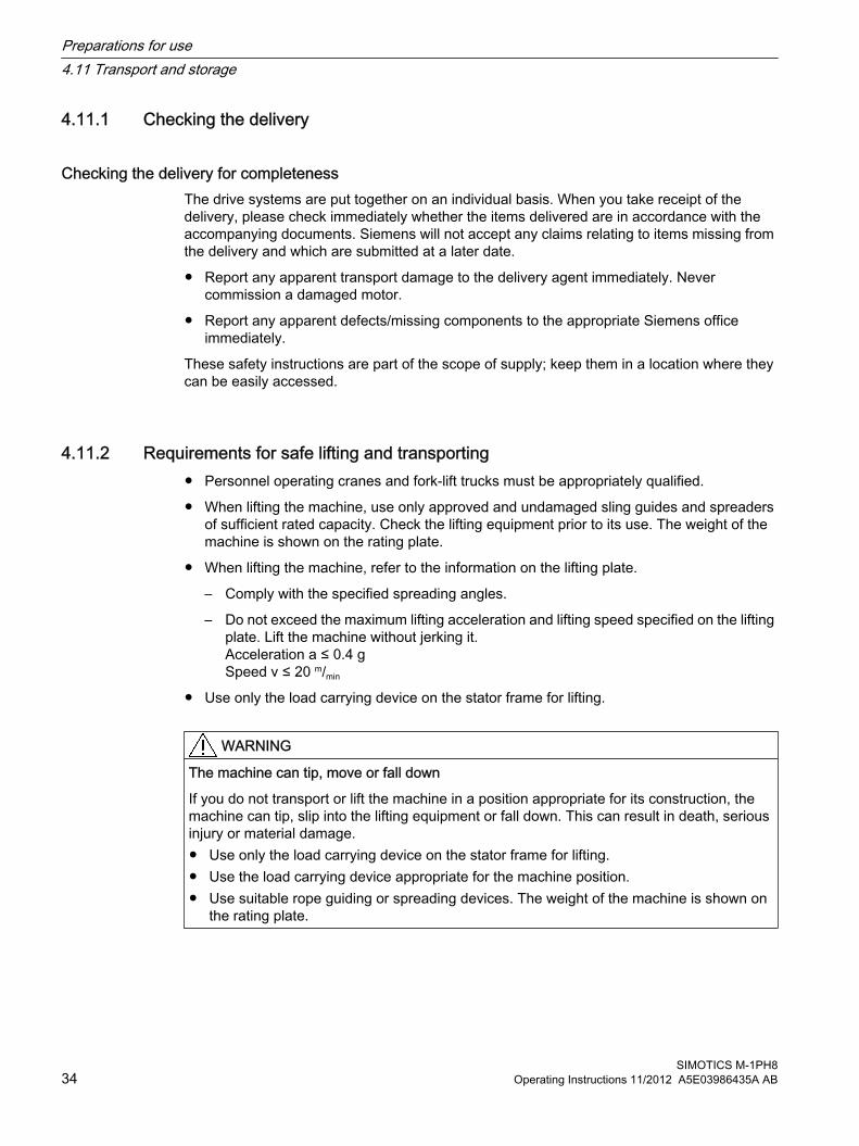
4.11.2 Requirements for safe lifting and transporting● Personnel operating cranes and fork-lift trucks must be appropriately qualified.
● When lifting the machine, use only approved and undamaged sling guides and spreaders of sufficient rated capacity. Check the lifting equipment prior to its use. The weight of the machine is shown on the rating plate.
● When lifting the machine, refer to the information on the lifting plate.
– Comply with the specified spreading angles.
– Do not exceed the maximum lifting acceleration and lifting speed specified on the lifting plate. Lift the machine without jerking it.Acceleration a ≤ 0.4 gSpeed v ≤ 20 m/min
● Use only the load carrying device on the stator frame for lifting.
WARNING
The machine can tip, move or fall down
If you do not transport or lift the machine in a position appropriate for its construction, the machine can tip, slip into the lifting equipment or fall down. This can result in death, serious injury or material damage.● Use only the load carrying device on the stator frame for lifting.● Use the load carrying device appropriate for the machine position. ● Use suitable rope guiding or spreading devices. The weight of the machine is shown on
the rating plate.
Preparations for use4.11 Transport and storage
SIMOTICS M-1PH834 Operating Instructions 11/2012 A5E03986435A AB

WARNING
The machine can tip, move or fall down
If the center of gravity of a load is not located centrally between the attachment points, the motor can tip over or slip out of the lifting equipment and fall when it is being transported or lifted. This can result in death, serious injury or material damage.● Comply with the handling instructions on the machine when transporting it.● Be aware of the possibility of different loads on the sling ropes or lifting straps and the
carrying capacity of the lifting equipment.● Always take account of the center of gravity when transporting or lifting the motor. If the
center of gravity is not located centrally between the attachment points, then position the hoisting hook above the center of gravity.
4.11.3 Lifting and transportingThere are two lifting eyebolts for horizontal transport of the motor. Always transport and lift the motor by the lifting eyebolts.
● Only lift the motor at the lifting eyebolts on the bearing end shields. To hoist the motor, in particular if there are built-on assemblies, use suitable cable-guidance or spreading equipment.
● Pay attention to the lifting capacity of the hoisting gear. The weight of the motor is specified on the rating plate.
Figure 4-2 Lifting the machine (schematic representation)
Preparations for use4.11 Transport and storage
SIMOTICS M-1PH8Operating Instructions 11/2012 A5E03986435A AB 35

Lifting force-ventilated motor in type of construction IM V5 with side-mounted terminal boxProceed as follows if you wish to lift a machine with type of construction IM V5 and with side-mounted terminal box:
1. Screw off the external fan.
2. Screw in the eyebolts supplied and use these to lift the machine.
3. Screw on the external fan again after the work has been completed.
Rotor shipping brace Machines ordered with the "Increased radial force" option are equipped with cylindrical-roller bearings and a rotor shipping brace.
NOTICE
Transport damage if the rotor shipping brace device is not used.
The motor can be damaged if it is jolted during transport. Material damage can result.● Always transport the motor with the rotor shipping brace supplied. It must be securely
attached during transportation.● Only remove it before pushing on the drive element.● When the motor has to be transported after the drive element is pushed on you must take
other appropriate measures to fix the axial position of the rotor.
① Sleeve② Shaft screw
Figure 4-3 Rotor shipping brace
Table 4-2 Tightening torque for rotor shipping brace
Type Thread in the shaft end Tightening torque Preload1PH818. M20 50 Nm 12 kN1PH822. M20 50 Nm 12 kN1PH828. M24 100 Nm 20 kN
Preparations for use4.11 Transport and storage
SIMOTICS M-1PH836 Operating Instructions 11/2012 A5E03986435A AB
4.11.4 Transporting a force-ventilated motor that has already been in operationIf you have already operated the motor and now want to transport it, proceed as follows:
1. Allow the motor to cool down.
2. Remove the connections provided by the customer.
3. Fit the rotor shipping brace.
4. Only use the eyebolts on the bearing shields to transport and lift the motor.
NoteStore the rotor locking device
Be sure to store the rotor locking device. It must be remounted for possible disassembly and transport.
4.11.5 Transporting the machine set
WARNING
Falling down of the machine
The lifting lugs on the machine are designed only for the weight of the machine. If a machine set is lifted and transported by a single machine, this can lead to mechanical failure of the lifting lug. The machine or machine set may fall. This can result in death, serious injury or material damage.● Do not lift machine sets by attaching lifting tackle to the individual machines.● Use only the equipment provided, e.g. the openings or lugs on the base plates, for
transporting machine sets. Note the maximum capacity of the lifting lug.
NotePlace the machine in a secure and raised position
In order to obtain easy and safe access to the underside of the machine, place it in a secure and raised position.
DANGER
Standing under suspended loads
If the lifting gear or load handling attachments were to fail, the machine could fall. This can result in death, serious injury or material damage.
Never remain under the machine when it is raised.
Preparations for use4.11 Transport and storage
SIMOTICS M-1PH8Operating Instructions 11/2012 A5E03986435A AB 37

4.11.6 StorageThe motors can be stored for up to two years in dry, dust-free and vibration-free rooms without reducing the specified storage time.
NOTICE
Seizure damage to bearings
If the motors are stored incorrectly there is a risk of bearing seizure damage such as brinelling, for example as a result of vibrations.
Read the following storage instructions.
Preparation● Fit the rotor shipping brace.
● Apply a preserving agent such as Tectyl to bare external components such as shaft ends, if this has not already been applied in the factory.
Storing indoors
NOTICE
Damage caused as a result of outdoor storage
Storing the machine outdoors can result in it being damaged. Ensure that the machine is only stored in areas that comply with the following conditions.
● Store the motor in an area that meets the following criteria:
– Dry, dust-free, frost-free and vibration-free The relative air humidity should be lower than 60% and the temperature should not drop below -15 °C in accordance with EN 60034-1.
– It must be well ventilated.
– Offers protection against extreme weather conditions
– The air in the storage area must not contain any harmful gases.
● Protect the motor from shocks and humidity.
● Cover the motor properly.
● Avoid contact corrosion:
– Every three months, remove the shipping brace and rotate the shaft end by hand.
– Then reattach the rotor shipping brace.
Preparations for use4.11 Transport and storage
SIMOTICS M-1PH838 Operating Instructions 11/2012 A5E03986435A AB

Protection against humidity ● If a dry storage area is not available, then take the following precautions:
– Wrap the motor in humidity-absorbent material and then wrap it in film to create an air-tight unit.
– Include several bags of desiccant in the seal-tight packaging. Check the desiccant and replace as required.
– Place a humidity meter in the seal-tight packaging to indicate the level of air humidity inside it.
– Inspect the motor regularly.
WARNING
Explosion hazard during commissioning
Storing the machine at temperatures that do not fall within the specified limits can damage the material of the seals and cause them to fail. There is also a risk that potentially explosive gaseous atmosphere may enter the machine and ignite during commissioning. Explosions can occur.
This can result in death, serious injury or material damage.
The materials used are specially designed for the temperature range required by the customer. Do not store the motor in conditions that lie outside the specified temperature limits. The relevant temperature limits are specified on the rating plate.
4.11.7 Attaching the rotor shipping brace prior to storageThe machine is delivered with mounted rotor shipping brace. If the machine has already been operational, mount the rotor shipping brace prior to packing and/or storing. This prevents damage to the bearings.
If the rotor shipping brace is not attached on a motor in storage, make sure that you turn the rotor through 360° regularly to prevent the occurrence of damage as a result of standstill.
NOTICE
Bearing damage caused by vibrations
If storage conditions are inappropriate there is a risk of bearing seizure damage. This can result in material damage, such as damage to bearings caused by vibration.
On machines that have been supplied with a rotor shipping brace, secure the rotor as per the notes on transportation. Protect the machine against strong radial vibrations, since the rotor shipping brace might not absorb these completely.
Preparations for use4.11 Transport and storage
SIMOTICS M-1PH8Operating Instructions 11/2012 A5E03986435A AB 39

NOTICE
Bearing damage
If the customer has already mounted parts, for example coupling, belt pulley, etc., the bearing can be damaged during transport.
In this case, make sure that the customer uses a rotor locking device.
4.11.8 Long-term storageIf you are storing a machine for more than six months, you must check its condition every six months.
● Check the machine for damage.
● Carry out any necessary maintenance work.
● Document all preservation measures taken so that they can be reversed before the machines are put back into service.
● Provide air-conditioning for the storage room.
CondensationCondensation can collect in the machine as a result of sharp fluctuations in ambient temperature, exposure to direct sunlight, high levels of humidity in the storage location or intermittent operation/variations in load during operation.
NOTICE
Damage caused by condensation
If the stator winding is damp, its insulation resistance is reduced. This results in voltage flashovers that can destroy the winding. Condensation can also cause rusting inside the machine.
Preparations for use4.11 Transport and storage
SIMOTICS M-1PH840 Operating Instructions 11/2012 A5E03986435A AB
4.11.9 Protection against corrosionIf the machine is stored in dry conditions, then apply the subsequently listed anti-corrosion measures:
● Storage up to six months:Apply a coat of corrosion protective compound to all accessible bare metal parts such as the exposed shaft extension, flange or machine feet.
● Storage for longer than six months:Apply a coat of anti-corrosion compound which provides long-term protection, e.g. Tectyl 506.
● Inspect the machine regularly and apply an additional coating of corrosion protection if necessary.
Document all preservation measures taken so that they can be reversed before the machines are put back into service.
4.12 Converter operation
4.12.1 Connection to a converter
Selecting and connecting the cable● Use Motion Connect cables or symmetrically constructed, shielded cables to connect the
motor to a converter. The cable shielding, made up of as many strands as possible, must have good electrical conductivity. Braided shields made of copper or aluminum are well suited.
● The shield must be connected at both ends to the motor and the converter; unshielded cable ends must be kept as short as possible.
● To ensure effective discharge of high-frequency currents, make the shield contact over the largest possible area, i.e. as a 360° contact on the converter and motor, e.g. using EMC glands at the cable entry points.
Preparations for use4.12 Converter operation
SIMOTICS M-1PH8Operating Instructions 11/2012 A5E03986435A AB 41

Measures to reduce bearing currentsTo specifically reduce and prevent damage caused by bearing currents, you must consider the system as a whole, which comprises the motor, converter, and driven machine. The following precautions help to prevent bearing currents:
● Setting up a properly meshed grounding system in the system as a whole, with low impedance for high-frequency currents
● No potential difference between the motor, converter, and working machine.
– Use symmetrical, shielded connecting cables.
– Connect the cable shield at both ends over the greatest possible surface area (360° contact).
– Use equipotential bonding conductors between the motor and the driven machine as well as between the motor and the converter
● Use iron cores mounted above the motor connecting cable at the converter output. These help to reduce common-mode components. The Siemens sales representative is responsible for selection and dimensioning.
● Limit the voltage rate of rise by using an output filter to dampen harmonic components in the output voltage
4.12.2 Insulated bearings for converter operationIf the machine is operated at a low-voltage converter such as SINAMICS G150 / S150 / S120, then an insulated bearing and a speed encoder with insulated storage (option) is mounted on the non-drive end.
For 1PH818, the insulated bearings are optional; for 1PH822 and 1PH828, insulated bearings are standard.
Comply with the plates on the machine relating to bearing insulation and possible bridges.
① Driving machine ④ Insulated bearings② Motor ⑤ Insulated tachometer fitting③ Coupling
Figure 4-4 Schematic representation of a single drive
Preparations for use4.12 Converter operation
SIMOTICS M-1PH842 Operating Instructions 11/2012 A5E03986435A AB
NOTICE
Bearing damage
The bearing insulation must not be bridged. Damage may be caused to the bearings if there is a flow of current.● Also for subsequent installation work, such as the installation of an automatic lubrication
system or a non-insulated vibration sensor, make sure that the bearing insulation cannot be bridged.
● Contact your Service Center, if necessary.
See alsoService and Support (Page 125)
4.12.3 Operation with insulated couplingIf you connect two motors in series in "tandem operation", fit a coupling between the motors; this coupling should satisfy Directive 94/9/EC or the regulations that apply in the country where the equipment is installed..
Preparations for use4.12 Converter operation
SIMOTICS M-1PH8Operating Instructions 11/2012 A5E03986435A AB 43
Preparations for use4.12 Converter operation
SIMOTICS M-1PH844 Operating Instructions 11/2012 A5E03986435A AB

Mounting 5
When carrying out any work on the machine, observe the general safety instructions (Page 13) and the specifications contained in EN 50110‑1 regarding working safely with and on electrical machines.
NoteLoss of conformity with European directives
In the delivery state, the machine corresponds to the requirements of the European directives. Unauthorized changes or modifications to the motor lead to the loss of conformity with the European directives and the loss of warranty.
WARNING
Explosion hazard when making modifications to the machine
Substantial modifications to the machine are not permitted – or may only be performed by the manufacturer. Otherwise an explosion can occur in an explosive atmosphere. This can result in death, serious injury or material damage.
Please contact the Service Center, if necessary.
NOTICE
High temperatures
The motor components get very hot during operation. High temperatures can damage mounting parts such as the cable insulation. ● Temperature-sensitive parts such as normal cables or electronic components must not
rest against or be attached to mounted machine parts.● Only use heat-resistant mounting parts. The connecting cables and cable entries must be
suitable for the ambient temperature.
5.1 Insulation resistance and polarization indexMeasuring the insulation resistance and polarization index (PI) provides information on the condition of the machine. It is therefore important to check the insulation resistance and the polarization index at the following times:
SIMOTICS M-1PH8Operating Instructions 11/2012 A5E03986435A AB 45

● Before starting up a machine for the first time
● After an extended period in storage or downtime
● Within the scope of maintenance work
The following information is provided regarding the state of the winding insulation:
● Is the winding head insulation conductively contaminated?
● Has the winding insulation absorbed moisture?
As such, you can determine whether the machine needs commissioning or any necessary measures such as cleaning and/or drying the winding:
● Can the machine be put into operation?
● Must the windings be cleaned or dried?
Detailed information on testing and the limit values can be found here:
"Testing the insulation resistance and polarization index"
5.2 Testing the insulation resistance and polarization index
WARNING
Hazardous voltage at the terminals
During and immediately after measuring the insulation resistance or the polarization index (PI) of the stator winding, hazardous voltages may be present at some of the terminals. Contact with these can result in death, serious injury or material damage.● If any power cables are connected, check to make sure line supply voltage cannot be
delivered.● Discharge the winding after measurement until the risk is eliminated, e.g. using the
following measures:– Connecting the terminals with ground potential until the recharge voltage drops to a
non-hazardous level– Connecting the connecting cable
Measure the insulation resistance1. Before you begin measuring the insulation resistance, please read the manual for the
insulation resistance meter you are going to use.
2. Disconnect any connected main-circuit cables from the terminals before measuring the insulation resistance.
Mounting5.2 Testing the insulation resistance and polarization index
SIMOTICS M-1PH846 Operating Instructions 11/2012 A5E03986435A AB

3. Measure the insulation resistance of the winding in relation to the machine housing and the winding temperature. The winding temperature should not exceed 40° C during the measurement. Convert the measured insulation resistances to the reference temperature of 40° C according to the formula in the following table. This thereby ensures that the minimum values specified can be compared.
4. Read out the insulation resistance one minute after applying the measuring voltage.
Measuring the polarization index1. To determine the polarization index, measure the insulation resistances after one minute
and ten minutes.
2. Express the measured values as a ratio:PI = Rinsul 10 min / Rinsul 1 minModern measuring devices display these values automatically following the measurement.
Limit values for insulation resistance and polarization index of the stator windingThe following table indicates the measuring voltage and limit values for the insulation resistance and PI. These values correspond to recommendations in IEEE 43‑2000. In addition, a critical insulation resistance is specified for the stator winding, which is the minimum requirement for further operation, e.g. following a long-term machine downtime.
Table 5-1 Stator winding insulation resistance at 40° C
Urated [V]
Umeas [V]
RC [MΩ]
RC, operation
[MΩ] RT
[MΩ] PI
U ≤ 1000 500 ≥ 5 0.2 MΩ/kV(≈0.5 MΩ/kV at 25° C)
2.0
1000 ≤ U ≤ 2500 500 (max. 1000) 100 1.8 MΩ/kV(≈5 MΩ/kV at 25° C)2500 < U ≤ 5000 1000 (max. 2500)
5000 < U ≤ 12000 2500 (max. 5000)U > 12000 5000 (max. 10000)
Urated = rated voltage, see the rating plateUmeas = DC measuring voltageRC = critical or minimum insulation resistance at reference temperature of 40° CRC = minimum insulation resistance after cleaning/repair at 40° CRC, operation = critical insulation resistance during operation at 40° CRT = insulation resistance converted to current measuring/winding temperaturePI = polarization index Rinsul 10 min / Rinsul 1 min. (T < 40° C)T = current measuring/winding temperature
Mounting5.2 Testing the insulation resistance and polarization index
SIMOTICS M-1PH8Operating Instructions 11/2012 A5E03986435A AB 47

Note the following:● When measuring at winding temperatures other than 40 °C, the measured value must be
converted to the reference temperature of 40 °C. The value is calculated using the formula specified in the table from IEEE 43‑2000. In this case, doubling or halving the insulation resistance at a temperature change of 10 K is used as the basis.
– The insulation resistance halves every time the temperature rises by 10 K.
– The resistance doubles every time the temperature falls by 10 K.
● Dry, new windings have an insulation resistance of between 100 ... 2000 MΩ, or even higher values, if required. Insulation resistance close to the minimum value could be due to humidity and/or dirt accumulation. However, the size of the winding, the rated voltage and other characteristics affect the insulation resistance and may need to be taken into account when determining measures.
● Over its operating lifetime, the motor winding insulation resistance can drop due to ambient and operational influences. Depending on the rated voltage, the critical insulation resistance value is to be calculated by multiplying the rated voltage (kV) by the specific critical resistance value and then converted to the current winding temperature at the time of the measurement, see previous table.
Example calculationCritical resistance for a rated voltage (VN) of 3.3 kV:
3,3 kV x 1,8 MΩ / kV = 6 MΩ at 40 °C.
A winding temperature of T = 25° C during the measurement, results in a critical insulation resistance of 16.5 MΩ.
NOTICE
Damage to insulation
If the critical insulation resistance is reached or undershot, this can damage the insulation and cause voltage flashovers. ● Contact your Siemens Service Center.● If the measured value is close to the critical value, you must subsequently check the
insulation resistance at shorter intervals.
5.3 Preconditions for correct alignment and secure attachment Detailed specialist knowledge of the following measures is required in order to correctly align and securely fit the equipment.
● Preparing the foundation
● Selecting and mounting the coupling
● Measuring the concentricity and axial eccentricity tolerances
● Positioning the machine
Mounting5.3 Preconditions for correct alignment and secure attachment
SIMOTICS M-1PH848 Operating Instructions 11/2012 A5E03986435A AB
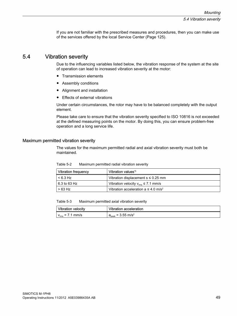
If you are not familiar with the prescribed measures and procedures, then you can make use of the services offered by the local Service Center (Page 125).
5.4 Vibration severityDue to the influencing variables listed below, the vibration response of the system at the site of operation can lead to increased vibration severity at the motor:
● Transmission elements
● Assembly conditions
● Alignment and installation
● Effects of external vibrations
Under certain circumstances, the rotor may have to be balanced completely with the output element.
Please take care to ensure that the vibration severity specified to ISO 10816 is not exceeded at the defined measuring points on the motor. By doing this, you can ensure problem-free operation and a long service life.
Maximum permitted vibration severityThe values for the maximum permitted radial and axial vibration severity must both be maintained.
Table 5-2 Maximum permitted radial vibration severity
Vibration frequency Vibration values1)
< 6.3 Hz Vibration displacement s ≤ 0.25 mm6.3 to 63 Hz Vibration velocity vrms ≤ 7.1 mm/s> 63 Hz Vibration acceleration a ≤ 4.0 m/s2
Table 5-3 Maximum permitted axial vibration severity
Vibration velocity Vibration accelerationvrms = 7.1 mm/s apeak = 3.55 m/s2
Mounting5.4 Vibration severity
SIMOTICS M-1PH8Operating Instructions 11/2012 A5E03986435A AB 49

Figure 5-1 Max. permissible vibration velocity, taking into account the vibration displacement and vibration acceleration
To evaluate the vibration velocity, the measuring equipment must fulfill the requirements of ISO 2954.
The vibration acceleration must be measured as a peak value in the time range in a frequency band of 10 to 2000 Hz.
If excitation in excess of 2000 Hz (e.g. meshing frequencies) is to be expected, the measurement range must be adapted accordingly. This does not alter the maximum permissible values.
5.5 Aligning the machine
Vertical and horizontal alignment The following measures are required in order to compensate any radial offset at the coupling and to horizontally adjust the electric motor with respect to the driven load:
● Place shims under the motor feet to position it vertically and to prevent stress/distortion. The number of shims should be kept as low as possible, so use as few thicker shims as possible, instead of several thinner shims.
● For horizontal positioning, push the motor sideways on the foundation Pay attention to maintaining the axial position.
● When positioning the motor, ensure that a uniform axial gap is maintained around the coupling.
NoteAlignment accuracy
Remember to take account of data concerning the alignment accuracy of the driven load and the coupling.
Mounting5.5 Aligning the machine
SIMOTICS M-1PH850 Operating Instructions 11/2012 A5E03986435A AB
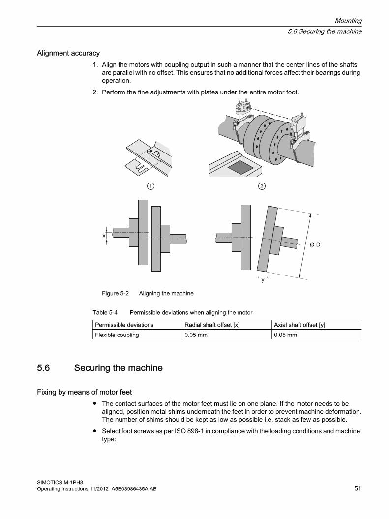
Alignment accuracy 1. Align the motors with coupling output in such a manner that the center lines of the shafts
are parallel with no offset. This ensures that no additional forces affect their bearings during operation.
2. Perform the fine adjustments with plates under the entire motor foot.
Figure 5-2 Aligning the machine
Table 5-4 Permissible deviations when aligning the motor
Permissible deviations Radial shaft offset [x] Axial shaft offset [y]Flexible coupling 0.05 mm 0.05 mm
5.6 Securing the machine
Fixing by means of motor feet ● The contact surfaces of the motor feet must lie on one plane. If the motor needs to be
aligned, position metal shims underneath the feet in order to prevent machine deformation.The number of shims should be kept as low as possible i.e. stack as few as possible.
● Select foot screws as per ISO 898-1 in compliance with the loading conditions and machine type:
Mounting5.6 Securing the machine
SIMOTICS M-1PH8Operating Instructions 11/2012 A5E03986435A AB 51

● Use foot screws with a minimum property class of 8.8.
● Pin the mounting feet to the customer foundation for motors with types of construction B6, B7, B8, V5 and V6.
Type Foot screw size1PH818. M121PH822. M161PH828. M20
Flange mounting The flange is only used to transfer the torque. Due to the empty weight or as a result of vibrations that arise if the flange is too soft, the motor can be damaged if it is only fastened via the flange.
1. Fasten the flange-mounted motors via a stable motor suspension and support them via the end shield feet (foot flange type of construction).
2. During commissioning, ensure that the permitted vibration values are maintained in accordance with ISO 10816‑3.If the motor is to be only flange mounted, then the maximum speed nmax is reduced for rigid foundations according to the following table:
Type Maximum speed nmax
1PH818. 3000 1/min
1PH822. 2500 1/min
1PH828. 2000 1/min
Maximum speed for a rigid foundation and flange mounting
5.7 Tightening torques for screw and bolt connectionsBolt locking devices ● Refit nuts or bolts that are mounted together with locking, resilient, and/or force-distributing
elements with identical, fully-functional elements when re-assembling. Always renew keyed elements.
● When screwing together threads secured with a liquid adhesive, use a suitable medium such as Loctite 243.
● Always use suitable securing devices or removable adhesives (e.g., Loctite 243) when installing fixing bolts with a clamping length of less than 25 mm. The clamping length is taken as the distance between the head of the bolt and the point at which the bolt is screwed in.
Tightening torques The bolted connections with metal contact surfaces, such as end shields, bearing cartridge parts, terminal box parts bolted onto the stator frame, should be tightened to the following torques, depending on the thread size:
Mounting5.7 Tightening torques for screw and bolt connections
SIMOTICS M-1PH852 Operating Instructions 11/2012 A5E03986435A AB

Table 5-5 Tightening torques for bolted connections with a tolerance of ±10%.
Case M4 M5 M6 M8 M10 M12 M16 M20 M24 M30 M36 M42 M48 M56 A 1,2 2,5 4 8 13 20 40 52 80 150 - - - - NmB 1,3 2,6 4,5 11 22 38 92 180 310 620 1080 1700 2600 4200 NmC 3 5 8 20 40 70 170 340 600 1200 2000 3100 4700 7500 Nm
ApplicationsThe above-mentioned tightening torques apply for the following applications:
● Case AApplies to electrical connections in which the permissible torque is normally limited by the bolt materials and/or the current carrying capacity of the insulators, with the exception of the busbar connections in case B.
● Case BApplies to bolts screwed into components made from lower-strength materials (e. g. aluminum) and to bolts of strength class 8.8 to ISO 898-1.
● Case CApplies to bolts of strength class 8.8 or A4-70 to ISO 898-1, but only to bolts screwed into components made from higher-strength materials (e. g. gray cast iron, steel or cast steel).
NoteNon-standard tightening torques
Different tightening torques for electrical connections and bolted connections for parts with flat seals or insulating parts are specified in the relevant sections and drawings.
5.8 Mounting the output elements
Balance quality The rotor is dynamically balanced. For shaft extensions with featherkeys, the balancing type is specified using the following coding on the face of the drive end of the shaft:
● "H" means balancing with a half feather key
● "F" means balancing with a whole feather key.
Figure 5-3 Balancing type on the drive-end side
Mounting5.8 Mounting the output elements
SIMOTICS M-1PH8Operating Instructions 11/2012 A5E03986435A AB 53

Pushing on the power output elements ● Prerequisites:
– The coupling and/or the output element must be appropriately dimensioned for the operating case at hand.
– Comply with the coupling manufacturer's instructions.
– Make sure that the balancing type of the transmission element correctly matches the type of balance of the rotor.
– Use only ready drilled and balanced transmission elements. Check the hole diameters and the balancing status before pulling them on. Thoroughly clean the shaft extension.
● Pulling on:
– Warm up the transmission elements to expand them before pulling them on. Select the temperature difference for the heating process to suit the coupling diameter, fit and material. See the coupling manufacturer's instructions.
– Power output elements may only be pushed on or pulled off with the correct equipment. The transmission element must be pulled on in one continuous operation via the front thread holes in the shaft or pushed on by hand.
– Do not strike it with a hammer, as this would damage the bearings.
Shaft extensions with feather key To maintain the balancing quality, you have the following options:
● If the transmission element is shorter than the feather key with balancing type "H", then you must machine off the section of feather key protruding from the shaft contour and transmission element in order to maintain the balance quality.
● If the output element is mounted up to the shaft shoulder for motors with full-key balancing "F", or if the output element is longer than the motor shaft extension, then when balancing the coupling or belt pulley, take into account that the feather key does not completely fill the slot in the hub.
WARNING
The feather key can fall out
The feather keys are only locked against falling out during shipping. If a machine with two shaft extensions does not have an output element on one shaft extension, the feather key can fall out during operation.
Death or serious injury can result.● Do not operate the machine unless the transmission elements have been pulled on.● On shaft extensions without output element, make sure that the feather key cannot fall
out and shorten it by approximately half for balance type "H".
Mounting5.8 Mounting the output elements
SIMOTICS M-1PH854 Operating Instructions 11/2012 A5E03986435A AB

NoteType of balancing
In the case of shaft extensions with feather keys, the type of balancing is also included on the rating plate next to the CE mark.
Mounting5.8 Mounting the output elements
SIMOTICS M-1PH8Operating Instructions 11/2012 A5E03986435A AB 55

Mounting5.8 Mounting the output elements
SIMOTICS M-1PH856 Operating Instructions 11/2012 A5E03986435A AB

Electrical connection 6
When carrying out any work on the machine, observe the general safety instructions (Page 13) and the specifications contained in EN 50110‑1 regarding working safely with and on electrical machines.
NoteService Center
If you require support when electrically connecting up the motor, please contact the (Page 125) Service Center.
6.1 Safety instructions relating to the electrical connection
WARNING
Connected parts can loosen
If you use fixing elements made from the wrong material or apply the wrong tightening torque, this could impair current transfer or cause connecting parts to become loose. Fastening elements can work loosely, so that the minimum air clearances are no longer maintained. Sparking formation may occur, in an explosive atmosphere it can lead to an explosion. This could result in death, serious injury or material damage to the machine or even in failure, which could in turn lead indirectly to material failure of the system.● Tighten the screwed connections to the specified tightening torques.● Observe any specifications regarding the materials from which fixing elements must be
made.● When performing servicing, check the fastenings.
See alsoTightening torques for screw and bolt connections (Page 52)
SIMOTICS M-1PH8Operating Instructions 11/2012 A5E03986435A AB 57

6.2 Preparation
6.2.1 Selecting cablesTake the following criteria into account when selecting the connecting cables:
● Rated current
● Rated voltage
● Where necessary, the service factor
● System-dependent conditions, such as ambient temperature, routing type, cable cross-section as defined by required length of cable, etc.
● Requirements to IEC / EN 60204‑1
● Requirements to IEC / EN 60079-14
● Configuration notes
6.2.2 Connecting the grounding conductorThe grounding conductor of the motor must be in full conformance with the installation regulations, e.g. in accordance with IEC/EN 60204-1.
● Connect the ground conductor to the end shield of the motor. There is a fixing lug ① for the ground conductor at the designated connection point.
– The fixing lug ① is suitable for grounding high-frequency currents using HF ribbon cable with appropriately formed conductor ends.
Figure 6-1 Detailed view: Connection point ① for ground conductor
● When making connections, ensure the following:
– the connecting surface is bare and protected against corrosion using a suitable substance, e.g. acid-free Vaseline
– the flat and spring washers are located under the bolt head.
Electrical connection6.2 Preparation
SIMOTICS M-1PH858 Operating Instructions 11/2012 A5E03986435A AB

6.3 Connecting
Depending on the version, different terminal boxes may be installed on the machine. Dependent on the terminal box, different cable entries and options for the cable connection are possible. You can identify the terminal box installed on the machine via the illustrations in the following chapters.
6.3.1 Circuit diagramData on the connection and connecting the motor winding can be found in the circuit diagram in the cover of the terminal box.
6.3.2 Terminal designationWith the terminal designations according to IEC / EN 60034‑8, the following definitions apply to three-phase machines:
Table 6-1 Terminal designations using the 1U1-1 as an example
1 U 1 - 1 Designationx Index for pole assignment on pole-changing motors where applicable. A lower
index signifies a lower speed. Special case for split winding. x Phase designation U, V, W x Index for winding start (1) or end (2) or if there is more than one connection per
winding x Additional indices for cases in which it is obligatory to connect parallel power feed
cables to several terminals with otherwise identical designations
6.3.3 Laying cables● For explosion-proof machines use certified versions of cable glands and cable or lead
inlets. The cable glands are not included in the scope of supply. For loose cables, use twist-protection cable glands with strain relief.
● For fixed cables use EMC screwed cable glands. Screw the EMC cable glands into the threaded holes of the screw-off entry plate.
● Arrange the exposed connecting cables in the terminal box such that the PE conductor has excess length and the insulation of the cable strands cannot be damaged.
Electrical connection6.3 Connecting
SIMOTICS M-1PH8Operating Instructions 11/2012 A5E03986435A AB 59

● Use shielded cables.
● In the case of aluminum connecting bars, insert a steel washer between the cable lug and connecting bar. This prevents contact corrosion.
NOTICE
Close unused screw threads with a metallic locking screw certified for use in Zone 2 or Zone 22 or which is bonded in position and cannot be removed. This achieves the required IP degree of protection and high-frequency shielding.
6.3.4 Electrical connection dataCable entry and technical connection data depend on the mounted terminal box. You can find more information on the terminal box that is mounted in the ordering documentation or in the catalog.
1XB7 322 1XB7 422
Electrical connection6.3 Connecting
SIMOTICS M-1PH860 Operating Instructions 11/2012 A5E03986435A AB

1XB7 700 1XB7 712 (*)① main terminal ③ signal connection terminal② ground terminal ④ signal connection
Table 6-2 Data for electrical connection
Terminal box type 1XB7 322 1XB7 422 1XB7 700 1XB7 712 (*)Cable entry 2 x M50 x 1,5 2 x M63 x 1,5 3 x M75 x 1,5 4 x M75 x 1,5Max. poss. cable outer diameter 38 mm 53 mm 68 mm 68 mmNumber of main terminals 3 x M12 3 x M12 3 x 3 x M12 3 x 4 x M16Max. cross-section per terminal 2 x 50 mm2 2 x 70 mm2 3 x 150 mm2 4 x 185 mm2
Max. current per terminal ① 210 A 270 A 700 A 1150 ANumber of ground terminals 4 x M6 4 x M8 Terminal strip 4 x M16
① Current carrying capacity based on IEC / EN 60204-1or IEC / EN 60364-5-32(*) Terminal box 1XB7 712 is not used in hazardous areas of Zone 22.
6.3.5 Connection with cable lugs1. To connect the cables to the main terminals, select cable lugs that match the necessary
cable cross-section and appropriate screw size. The connectable cable cross section is determined by the cable lug size for example.
– Cable lug in accordance with DIN 46234 from 35 mm2 to 185 mm2,
– Cable lug in accordance with DIN 46235 from 35 mm2 to 185 mm2.Observe the possible outer diameter of the connecting cable in the chapter entitled "Electrical connection data".Connect only one conductor per cable lug.
2. Remove the insulation from the conductor ends so that the remaining insulation is almost long enough to reach the cable lug.
3. Fasten the cable lug to the end of the conductor correctly, e.g. by crimping.
4. If necessary, insulate the cable lugs in order to maintain the minimum clearances of 10 mm and the 20 mm creepage distance, which are normally available. The tightening torque for contact nuts and fixing screws depends on the size of the screw, see Case A in the table in ChapterTightening torques for screw and bolt connections (Page 52).
Electrical connection6.3 Connecting
SIMOTICS M-1PH8Operating Instructions 11/2012 A5E03986435A AB 61

Connection with cable lug at the terminal box 1XB7 322 / 1XB7 422
① Customer connecting cable② Internal motor connecting cable③ Copper spacer ring
Connection with cable lug at the terminal box 1XB7 700 / 1XB7 712
Note
Terminal box 1XB7 712 is not used in hazardous areas of Zone 22.
① Customer connecting cable② Connection bar
See alsoElectrical connection data (Page 60)
Electrical connection6.3 Connecting
SIMOTICS M-1PH862 Operating Instructions 11/2012 A5E03986435A AB

WARNING
Explosion hazard if cable lugs without side guards are used
For cable cross-sections under 70 mm2, cable lugs without side guard may twist. The minimum air clearances may be underrun and cause an explosion.
This can result in death, serious injury, or material damage.● For cable cross-sections under 70 mm2, use only cable lugs with side guard.● Make sure that the minimum air clearances are observed.
Use only sealing plugs, cable entries and conductor entries, that are certified and marked for use in the respective hazardous area (the zone).
● If you are using cable glands, use only certified cable glands with strain relief. Comply with the installation and operation conditions specified in the certificate for these cable glands and check that they have been complied with.
● Correctly close unused threads or holes, maintaining the IP degree of protection. The IP degree of protection is stamped on the rating plate.
● Replace any unused cable glands by certified screw plugs.
6.3.6 Connecting aluminum conductorsIf you are using aluminum conductors, comply in addition with the following:
● Use only cable lugs that are suitable for connecting aluminum conductors.
● Immediately before inserting the aluminum conductor, remove the oxide layer from the contact areas on the conductor and/or the mating piece, by brushing or filing.
● Then grease the contact areas immediately using neutral Vaseline in order to avoid re-oxidation.
NOTICE
The aluminum flow is determined by contact
The aluminum flow is determined by contact following installation. The connection with the clamping nuts can loosen as a result. The contact resistance would increase and the current-carrying be impeded; as a consequence the terminal box and the surrounding components could burn. This could result in material damage to the machine or even in total failure, which could in turn lead to indirect material damage to the system.
Retighten the clamping nuts after approximately 24 hours and then again after approximately four weeks. Make sure that the terminals are de-energized before you tighten the nuts.
Electrical connection6.3 Connecting
SIMOTICS M-1PH8Operating Instructions 11/2012 A5E03986435A AB 63
6.3.7 Completing connection work1. Before closing the terminal box, please check that:
– the electrical connections in the terminal box are tight and are in full compliance with the specifications above.
– The required clearances in air of 10 mm are maintained.
– Wire ends do not protrude.
– the inside of the terminal box is clean and free of any cable debris.
– all seals and sealing surfaces are undamaged.
– The connecting cables are arranged so that they do not come into contact with the machine, and the cable insulation cannot be damaged.
– Unused threads are closed with metal screw plugs certified for use in Zone 22 or bonded in position so they cannot be removed. The sealing elements can only be removed with a tool.
– The cable/conductor glands are fitted compliant with the specifications regarding degree of protection, cable routing type, permissible cable diameter etc.
2. Then close the terminal box with the terminal box cover fixing screws.
6.3.8 Internal equipotential bondingThe internal equipotential bonding between the grounding terminal in the box enclosure and the motor frame is established through the terminal box retaining bolts. The contact locations underneath the bolt heads are bare metal and protected against corrosion.
The standard cover fixing screws are sufficient for equipotential bonding between the terminal box cover and terminal box housing.
Note
Connecting points are provided on the enclosure or end shield to allow an outer PE conductor or equipotential bonding conductor to be connected; see "Connecting the grounding conductor".
See alsoConnecting the grounding conductor (Page 58)
Electrical connection6.3 Connecting
SIMOTICS M-1PH864 Operating Instructions 11/2012 A5E03986435A AB

6.4 Auxiliary circuits
6.4.1 Selecting cablesTake the following criteria into account when selecting the connecting cables for the auxiliary circuits:
● Rated current
● Rated voltage
● System-dependent conditions, such as ambient temperature, routing type, cable cross-section as defined by required length of cable, etc.
● Requirements to IEC / EN 60204‑1
● Requirements to IEC / EN 60079‑14
6.4.2 Connecting the auxiliary circuits
Cable entry and routing The cable entries and sealing plugs must be certified for use in Zone 22.
A plate is bolted to the terminal box housing via a rectangular cut-out through which the connecting cables are introduced. Refer to the machine documentation for the dimensions.
● Normally this plate is supplied without threaded holes for the cable glands. Adjust the number and size of the cable glands to the operational conditions.
● Seal the screwed sockets on the cable glands in accordance with the degree of protection for the machine (see rating plate).
6.4.3 Intrinsically safe circuits for sensors or probesObserve the IEC / EN 60079‑14 standard when selecting and routing connecting cables.
NOTICE
Intrinsically safe circuits for sensors or probes
If blue connection terminals are installed for sensors/probes, these sensors/probes must be connected to certified intrinsically safe circuits. This can otherwise result in damage. Ensure that you also observe the additional requirements in IEC / EN 60079‑14 for intrinsically safe equipment and the associated connecting cables.
Electrical connection6.4 Auxiliary circuits
SIMOTICS M-1PH8Operating Instructions 11/2012 A5E03986435A AB 65

NOTICE
Connection of temperature sensors to intrinsically safe circuits with certified evaluation devices
The temperature sensors may only be connected to intrinsically safe circuits with certified evaluation devices. The maximum permissible input currents and powers according to the EC type-examination certificate shall not be exceeded. This can otherwise result in damage.
If shielded, intrinsically safe temperature sensors are fitted in the stator winding, these must be connected using the blue connecting terminals. The shield is grounded at the laminated core; multiple grounding is not permitted.
6.4.4 Connecting an external fan
Preconditions ● Only use cables that comply with the relevant installation regulations regarding voltage,
current, insulation material, and load-carrying capacity.
● Before connecting the device, make sure that the line voltage matches the device voltage.
● Check whether the data on the fan rating plate matches the connection data.
● Cable glands are not included in the scope of delivery. Close unused cable entries, otherwise, the degree of protection is not maintained.
Type Supply voltage Current consumption1PH818. 1 AC 200 V … 277 V / 50Hz, 60 Hz (± 10 %) 1,45 ... 1,05 A1PH822. 1 AC 200 V … 277 V / 50Hz, 60 Hz (± 10 %) 2,3 ... 1,6 A1PH828. 3 AC 400 V / 50 Hz (± 10 %)
3 AC 400 V / 60 Hz (± 10 %)3 AC 480 V / 60 Hz (± 10 %)
2,55 A2,50 A2,50 A
Connection values for external fans
● The line voltage must fulfill the quality criteria stipulated by DIN EN 50160 and the defined standard voltages specified in DIN IEC 60038.
Procedure1. Open the terminal box of the external fan and route the cables into it. The cables are not
included in the scope of delivery.
2. Connect the protective conductor (PE).
3. Connect the other cables to the relevant terminals, refer to the connection diagram.Connection cables must not be subject to excessive tensile stress.
Note
For fans equipped with EC motor, the fan motor starts with a delay after the line voltage is connected.
Electrical connection6.4 Auxiliary circuits
SIMOTICS M-1PH866 Operating Instructions 11/2012 A5E03986435A AB
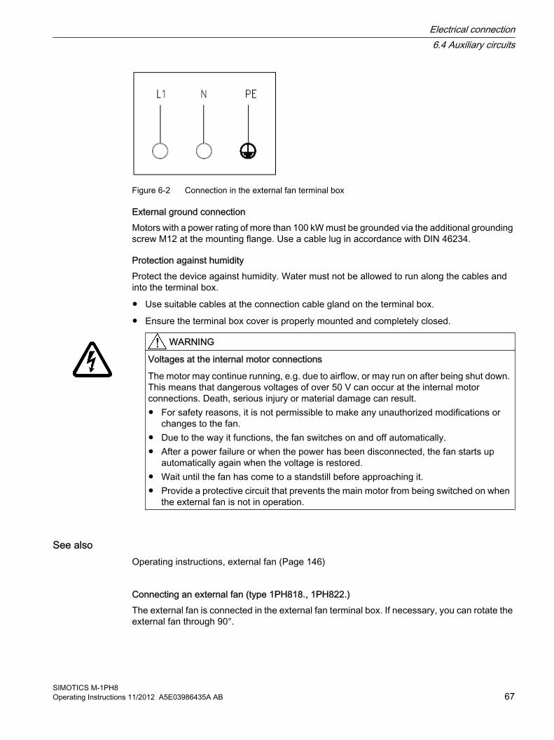
Figure 6-2 Connection in the external fan terminal box
External ground connectionMotors with a power rating of more than 100 kW must be grounded via the additional grounding screw M12 at the mounting flange. Use a cable lug in accordance with DIN 46234.
Protection against humidityProtect the device against humidity. Water must not be allowed to run along the cables and into the terminal box.
● Use suitable cables at the connection cable gland on the terminal box.
● Ensure the terminal box cover is properly mounted and completely closed.
WARNING
Voltages at the internal motor connections
The motor may continue running, e.g. due to airflow, or may run on after being shut down. This means that dangerous voltages of over 50 V can occur at the internal motor connections. Death, serious injury or material damage can result.● For safety reasons, it is not permissible to make any unauthorized modifications or
changes to the fan.● Due to the way it functions, the fan switches on and off automatically.● After a power failure or when the power has been disconnected, the fan starts up
automatically again when the voltage is restored.● Wait until the fan has come to a standstill before approaching it.● Provide a protective circuit that prevents the main motor from being switched on when
the external fan is not in operation.
See alsoOperating instructions, external fan (Page 146)
Connecting an external fan (type 1PH818., 1PH822.)The external fan is connected in the external fan terminal box. If necessary, you can rotate the external fan through 90°.
Electrical connection6.4 Auxiliary circuits
SIMOTICS M-1PH8Operating Instructions 11/2012 A5E03986435A AB 67
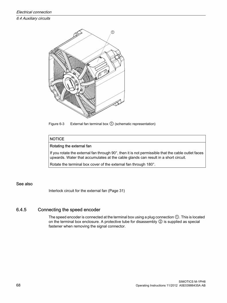
Figure 6-3 External fan terminal box ① (schematic representation)
NOTICE
Rotating the external fan
If you rotate the external fan through 90°, then it is not permissible that the cable outlet faces upwards. Water that accumulates at the cable glands can result in a short circuit.
Rotate the terminal box cover of the external fan through 180°.
See alsoInterlock circuit for the external fan (Page 31)
6.4.5 Connecting the speed encoderThe speed encoder is connected at the terminal box using a plug connection ①. This is located on the terminal box enclosure. A protective tube for disassembly ② is supplied as special fastener when removing the signal connector.
Electrical connection6.4 Auxiliary circuits
SIMOTICS M-1PH868 Operating Instructions 11/2012 A5E03986435A AB

Figure 6-4 Detailed view: Plug-in connection
Note
The plug-in connection may differ from the standard layout in the case of special orders. For versions without speed encoder, connection thread M16x1.5 is located here.
Cable outlet directions The sensor module is mounted on the motor terminal box. The sensor module can be rotated through approximately 235°. You can change the cable outlet directions by rotating the sensor module, as shown in the diagram below.
NOTICE
Damage to the sensor module
You can damage the sensor module if you turn it with a pipe wrench, a hammer, or similar tools.
Turn the sensor module by hand. The typical torque is approx. 4 ... 8 Nm.
Figure 6-5 Sensor Module ① mounted on the terminal box
Electrical connection6.4 Auxiliary circuits
SIMOTICS M-1PH8Operating Instructions 11/2012 A5E03986435A AB 69

NOTICE
Modifying the cable outlet direction
Changing the cable outlet direction by any improper means will damage the connecting cables.
The permissible rotation range must not be exceeded. A maximum of ten changes to the rotation angle of the Sensor Module are permissible within the rotation range.
6.4.6 Attach a protective tube for the signal connectorA protective tube is supplied as special fastener when removing the signal connector. Slide the protective tube to remove the signal connector over it and screw it down firmly.
Operation without special fastener is not permissible.
Figure 6-6 Slide the protective tube to remove the signal connector over the signal connector
Figure 6-7 Screw the protective tube to remove the connector to the end position
Electrical connection6.4 Auxiliary circuits
SIMOTICS M-1PH870 Operating Instructions 11/2012 A5E03986435A AB
WARNING
Risk of explosion
The disassembly protective tube and the signal plug must not be removed in an explosion-endangered environment or when under power. An explosion can result. This can result in death, serious injury or material damage.● Ensure that the ambient atmosphere is not combustible before you remove the
disassembly protective tube and the signal plug. ● The disassembly protective tube and the signal plug must be connected from the power
supply before being removed.
6.4.7 Connecting the temperature sensor● The temperature sensor is connected to the signal connector together with the speed
encoder signal.
● For the version without speed encoder, the temperature sensor is connected at the terminal strip.
● The motor has a reserve temperature sensor, which is also connected at the auxiliary terminal strip. Reconnect the temperature sensor as needed, e.g. if the previous temperature sensor fails.
6.4.8 Connection to a converter
Selecting and connecting the cable● Use Motion Connect cables or symmetrically constructed, shielded cables to connect the
motor to a converter. The cable shielding, made up of as many strands as possible, must have good electrical conductivity. Braided shields made of copper or aluminum are well suited.
● The shield must be connected at both ends to the motor and the converter; unshielded cable ends must be kept as short as possible.
● To ensure effective discharge of high-frequency currents, make the shield contact over the largest possible area, i.e. as a 360° contact on the converter and motor, e.g. using EMC glands at the cable entry points.
Electrical connection6.4 Auxiliary circuits
SIMOTICS M-1PH8Operating Instructions 11/2012 A5E03986435A AB 71

Measures to reduce bearing currentsTo specifically reduce and prevent damage caused by bearing currents, you must consider the system as a whole, which comprises the motor, converter, and driven machine. The following precautions help to prevent bearing currents:
● Setting up a properly meshed grounding system in the system as a whole, with low impedance for high-frequency currents
● No potential difference between the motor, converter, and working machine.
– Use symmetrical, shielded connecting cables.
– Connect the cable shield at both ends over the greatest possible surface area (360° contact).
– Use equipotential bonding conductors between the motor and the driven machine as well as between the motor and the converter
● Use iron cores mounted above the motor connecting cable at the converter output. These help to reduce common-mode components. The Siemens sales representative is responsible for selection and dimensioning.
● Limit the voltage rate of rise by using an output filter to dampen harmonic components in the output voltage
6.4.9 Converter operation on a grounded network
NOTICE
Damage resulting from protective conductor currents
When the machine is operated on a converter with current limiter, but without ground-fault monitoring, protective conductor currents of up to 1.7 times the external conductor current can arise if there is a ground fault on the output side. Neither the PE conductors of normally rated multi-core connecting cables nor the PE connecting points of normal terminal boxes are suitable for this purpose. Material damage can result.● Use an appropriately sized PE conductor.● Connect the PE conductor to the grounding terminal on the motor enclosure.
See alsoConnect metal shield in the terminal box (Page 73)
Electrical connection6.4 Auxiliary circuits
SIMOTICS M-1PH872 Operating Instructions 11/2012 A5E03986435A AB

6.4.10 Connect metal shield in the terminal box When you insert metal-armored cables into the terminal box or auxiliary terminal box, ground the metal shield in the terminal and in the operator control post.
NOTICE
Faults
If the metal shield is grounded just once, cable- or field-related interferences can occur. Ground the metal shield at least twice.
Electrical connection6.4 Auxiliary circuits
SIMOTICS M-1PH8Operating Instructions 11/2012 A5E03986435A AB 73

Electrical connection6.4 Auxiliary circuits
SIMOTICS M-1PH874 Operating Instructions 11/2012 A5E03986435A AB

Commissioning 7
When carrying out any work on the machine, observe the general safety instructions (Page 13) and the specifications contained in EN 50110‑1 regarding working safely with and on electrical machines.
7.1 Insulation resistance and polarization indexMeasuring the insulation resistance and polarization index (PI) provides information on the condition of the machine. It is therefore important to check the insulation resistance and the polarization index at the following times:
● Before starting up a machine for the first time
● After an extended period in storage or downtime
● Within the scope of maintenance work
The following information is provided regarding the state of the winding insulation:
● Is the winding head insulation conductively contaminated?
● Has the winding insulation absorbed moisture?
As such, you can determine whether the machine needs commissioning or any necessary measures such as cleaning and/or drying the winding:
● Can the machine be put into operation?
● Must the windings be cleaned or dried?
Detailed information on testing and the limit values can be found here:
"Testing the insulation resistance and polarization index" (Page 46)
7.2 Checks to be carried out prior to commissioning Once the system has been correctly installed, you should check the following prior to commissioning:
NoteChecks to be carried out prior to commissioning
The following list of checks to be performed prior to commissioning does not claim to be complete. It may be necessary to perform further checks and tests in accordance with the specific situation on-site.
SIMOTICS M-1PH8Operating Instructions 11/2012 A5E03986435A AB 75

● The machine is undamaged.
● The machine has been correctly installed and aligned, the transmission elements are correctly balanced and adjusted.
● All fixing screws, connection elements, and electrical connections have been tightened to the specified tightening torques.
● The operating conditions match the data provided in accordance with the technical documentation, such as degree of protection, ambient temperature, etc..
● Moving parts such as the coupling move freely.
● If the second shaft extension is not in use, its feather key is secured to prevent it from being thrown out, and cut back to roughly half its length if the rotor has balancing type "H" (standard type).
● All touch protection measures for moving and live parts have been taken.
● The rotor can spin without coming into contact with the stator.
● The bearing insulation is not bridged.
● The grounding and equipotential bonding connections have been made correctly.
● The machine is connected so that it rotates in the direction specified.
● Appropriately configured control and speed monitoring functions ensure that the motor cannot exceed the permissible speeds specified in the technical data. For this purpose, compare the data on the rating plate or, if necessary, the system-specific documentation.
● The minimum insulation resistance values are within tolerance.
● Minimum air clearances have been maintained.
● Any supplementary motor monitoring devices and equipment have been correctly connected and are functioning correctly.
● All brakes and backstops are operating correctly.
● At the monitoring devices, the values for "Warning" and "Shutdown" are set.
● While being operated on the converter, the motor cannot exceed the specified upper speed limit nmax or undershoot the lower speed limit nmin.If the design of the motor requires connection to a particular converter type, the rating plate will contain corresponding additional information.
● The converter is correctly parameterized. The parameterization data is specified on the rating plate of the machine. Information about the parameters is available in the operating instructions for the converter.
Commissioning7.2 Checks to be carried out prior to commissioning
SIMOTICS M-1PH876 Operating Instructions 11/2012 A5E03986435A AB

● If the motor has been stored for more than two years in a dry, dust-free and vibration-free room, prepare for commissioning as follows:
– Replace the rolling-contact bearings on motors with lifetime lubrication.
– Replace the grease in motors with re-greasing system.
● If stored under less favorable conditions, replacement of bearings or re-greasing must be carried out after a storage period of approx. 18 months.
● Appropriately configured control and speed monitoring functions ensure that the the permissible speeds specified on the rating plate cannot be exceeded.
● Any supplementary motor monitoring devices and equipment have been correctly connected and are fully functional.
Force-ventilated motors● All external fans fitted are ready for operation and have been connected so that they rotate
in the direction specified.
● The flow of cooling air is not impeded.
7.3 Switching on● See the operating instructions of the frequency converter for switching on.
● Before you switch on the motor, ensure that the parameters of the frequency converter have been assigned correctly.
● Use appropriate commissioning tools, such as "Drive ES" or "STARTER".
NOTICE
Operation noise or abnormal noises
The motor can be damaged by improper handling during transport, storage or set up. If a damaged motor is operated damage to the winding, bearings or, complete destruction of the motor can be the result.
If the motor is not running smoothly or is emitting abnormal noises, de-energize it, and determine the cause of the fault as the motor runs down.
Maximum speed The maximum rotational speed nmax is the highest permissible operating speed. The maximum rotational speed is specified on the rating plate.
Commissioning7.3 Switching on
SIMOTICS M-1PH8Operating Instructions 11/2012 A5E03986435A AB 77

7.4 Test runCommission the machine after assembly or inspection as follows:
● Start up the machine without a load. To do this, close the circuit breaker and do not, if at all possible, switch off prematurely.
● Switching the machine off again while it is starting up and still running at slow speed should be kept to a bare minimum, for example for checking the direction of rotation or for checking the required dimensions. Allow the machine to run down before switching it on again.
● Check the machine for noises or vibrations on the bearings or bearing shields as it runs.
● If the machine is not running smoothly or is emitting abnormal noises, de-energize it, and determine the cause of the fault as the motor runs down.
– If the mechanical operation improves immediately after the machine is switched off, then the cause is magnetic or electrical.
– If the mechanical operation is not improved after switching off, then the cause is mechanical. This can be an imbalance in the electrical machines or in the driven machine, poor alignment of the machine unit, operation of the machine with the system resonating (system = motor, base frame, foundation etc.).
● Continue to observe the motor for a while in no-load operation.
● If it runs perfectly, connect a load. Check whether it is running smoothly. Read off the values for voltage, current, and output and log them. If possible, read and log the corresponding values for the working machine.
NOTICE
Serious damage to the machine
The vibration values encountered during operation must be satisfied in accordance with DIN ISO 10816-3, otherwise the machine could be damaged or destroyed.
During operation, observe the vibration values in accordance with DIN ISO 10816‑3.
● Monitor and log the temperatures of the bearings, windings, etc., until the system reaches the steady state, in as much as this is possible with the available measuring equipment.
Commissioning7.4 Test run
SIMOTICS M-1PH878 Operating Instructions 11/2012 A5E03986435A AB

Operation 8
When carrying out any work on the machine, observe the general safety instructions (Page 13) and the specifications contained in EN 50110‑1 regarding working safely with and on electrical machines.
8.1 Safety guidelines in operation
WARNING
Live parts
Terminal boxes contain live electrical parts. If you open the terminal box cover, this can result in death, serious injury or material damage.
When the machine is in operation, the terminal boxes must remain closed at all times. Terminal boxes may be opened only when the machine is stopped and de-energized.
WARNING
Rotating and live parts
Rotating or live parts are dangerous. If you remove the required covers, this can result in death, serious injury or material damage.
Any covers that prevent live electrical or rotating parts from being touched, ensure compliance with a particular degree of protection or are required for ensuring proper air flows, and hence effective cooling, must not be opened during operation.
WARNING
Fire hazard resulting from hot surfaces
Certain parts of the machine become hot during operation. Severe burns can result from contact with these parts.● Check the temperature of the parts before touching them and take appropriate protective
measures if necessary.● Allow the machine to cool before starting work on the machine.
SIMOTICS M-1PH8Operating Instructions 11/2012 A5E03986435A AB 79

WARNING
Faults in operation
Deviations from normal operation such as increased power consumption, temperatures or vibrations, unusual noises or odors, tripping of monitoring devices, etc., indicate that the machine is not functioning properly. This can cause faults which can result in eventual or immediate death, serious injury or material damage. ● Immediately inform the maintenance personnel.● If you are in doubt, immediately switch off the motor, being sure to observe the system-
specific safety conditions!
NOTICE
Risk of corrosion due to condensate
Humid air can condense inside the machine during operation as a result of intermittent duty or load fluctuations. Condensate can collect inside the motor. Damage such as rust can result.
Make sure that any condensation can drain away freely.
8.2 Machine overheating caused by dust
WARNING
Explosion hazard due to overheating of the machine caused by a layer of dust
Layers of dust thicker than 5mm can insulate the machine, resulting in overheating. The maximum surface temperature of the machine cannot be adhered to. The dust can ignite, resulting in an explosion. This can result in death, serious injury or material damage.
Dust the machine regularly. Do not allow dust layers thicker than 5 mm to build up on the machine surface. Do not switch the machine on until the dust has been removed.
WARNING
Risk of explosion due to excessive bearing temperature
The surface temperature cannot be maintained within maximum permissible limits if the bearing becomes too hot. The dust can ignite, resulting in an explosion. This can result in death, serious injury or material damage.● Always check the bearing temperature.● In addition to the current-dependent overload protection device located in the three phases
of the connecting cable, we recommend that you also monitor the temperature rise in the motor with the aid of the temperature sensors built into the stator winding.
Operation8.2 Machine overheating caused by dust
SIMOTICS M-1PH880 Operating Instructions 11/2012 A5E03986435A AB

DANGER
Explosion hazard if the bridging is removed from the insulated bearing
Removing the factory-fitted bridging of the insulated bearing leads to potential differences between the rotor and the grounded motor. This can cause the generation of sparks, which especially in an explosive atmosphere can ignite surrounding dust or combustible gases. Explosions can occur. There is also a risk of an electric shock. Death, serious injury, or material damage will result.
Do not open the bridging of the bearing insulation during operation.
NOTICE
Periodic duty
For all operating modes, operate the external fan according to DIN EN 60034-1. Also for non-periodic operation, the machine can be thermally overloaded. This can result in damage to the machine.
In the case of extended non-operational periods, the fan should be in operation until the machine has approximately reached the temperature of the coolant, see S2-operation in DIN EN 60034‑1.
Use a suitable circuit to ensure that the external fan is appropriately operated.
8.3 Operation● After starting the motor, observe it for a while to see if it is running smoothly and check the
monitoring devices.
● Monitor operation and the monitoring devices regularly and record the values you read off.
NOTICE
Speed monitoring
The motor is designed for a certain speed range.
If a motor is operated at impermissible speeds damage to the winding, bearings, or complete destruction of the motor can be the result.
Ensure that the speeds specified on the rating plate are not exceeded by appropriately configuring controller and speed monitoring components.
Operation8.3 Operation
SIMOTICS M-1PH8Operating Instructions 11/2012 A5E03986435A AB 81

8.4 Switching-off force-ventilated motors● When switching-off, also observe the converter operating instructions.
● Switch off the external fan during longer standstill periods. Leave the fan on for approximately 30 minutes after switching off the motor to avoid overheating of the motor.
● If a standstill heating unit is available, switch it on.
8.5 Switching on again after an emergency switching-off● Check the motor before restarting the driven machine after an emergency off.
● Eliminate all the causes that have led to the emergency off
8.6 Stoppages
The stoppage is a shutdown for a period of time, during which the machine is stopped but remains at the location of use.
Under normal ambient conditions, e. g. the stopped machine is not exposed to any vibration, no increased level of corrosion, etc. in general, the following measures are necessary during stoppages.
Measures when motors are at standstill and ready for operation ● For longer periods when the motor is not being used, either energize the motor at regular
intervals (roughly once a month), or at least spin the rotor.
● Please refer to the section"Switching on" (Page 77) before switching on to recommission the motor.
NOTICE
Damage due to improper storage
The motor can be damaged if it is not stored properly. If the motor is out of service for extended periods of time, implement suitable anti-corrosion, preservation, and drying measures.
When recommissioning the motor after a long period out of service, carry out the measures recommended in the chapter entitled "Commissioning (Page 75)".
Operation8.6 Stoppages
SIMOTICS M-1PH882 Operating Instructions 11/2012 A5E03986435A AB

8.6.1 Avoidance of damage to roller bearings during stoppagesExtended stoppages at the identical or almost identical resting position of the roller bearings can lead to damage such as brinelling or formation of corrosion.
● During stoppages, regularly start the machine up for a brief period once a month, or at least turn the rotor over several times.If you have uncoupled the machine from the driven machine and secured the rotor with a rotor shipping brace, then remove this before turning the rotor over or starting the machine up.Make sure that the resting position of the roller bearings after the rotor has been turned over is different from what it previously had been. Use the fitted key or the coupling halves as reference markers.
● During re-commissioning, refer to the information in the "Commissioning" section.
8.6.2 Measurement of the insulation resistance after an extended stoppageMeasuring the insulation resistance and polarization index (PI) provides information on the condition of the machine. It is therefore important to check the insulation resistance and the polarization index at the following times:
● Before starting up a machine for the first time
● After an extended period in storage or downtime
● Within the scope of maintenance work
The following information is provided regarding the state of the winding insulation:
● Is the winding head insulation conductively contaminated?
● Has the winding insulation absorbed moisture?
As such, you can determine whether the machine needs commissioning or any necessary measures such as cleaning and/or drying the winding:
● Can the machine be put into operation?
● Must the windings be cleaned or dried?
Detailed information on testing and the limit values can be found here:
"Testing the insulation resistance and polarization index"
8.7 Decommissioning the machine
NOTICE
Damage as a result of an extended period out of service
If the machine is going to be out of service for longer than six months, then perform the necessary measures for anti-corrosion protection, preservation, packaging and drying. Otherwise damage to the machine will result.
Operation8.7 Decommissioning the machine
SIMOTICS M-1PH8Operating Instructions 11/2012 A5E03986435A AB 83

Record the decommissioning steps. This log will be useful upon recommissioning.
8.8 Re-commissioning the machineWhen you re-commission the machine, proceed as follows:
● Study the record made when the machine was decommissioned, and reverse the measures that were taken for conservation and storage.
● Perform the measures listed in the "Commissioning" section.
8.9 Faults
8.9.1 Inspections in the event of faultsNatural disasters or unusual operating conditions, such as overloading or short circuit, are faults that overload the machine electrically or mechanically.
Immediately perform an inspection after such faults.
Correct the cause of the fault as described in the respective remedial measures section. Repair any damage to the machine.
8.9.2 Electrical faults at force-ventilated motors
Note
When operating the machine with a converter, also refer to the operating instructions of the frequency converter if electrical faults occur.
Operation8.9 Faults
SIMOTICS M-1PH884 Operating Instructions 11/2012 A5E03986435A AB

Table 8-1 Electrical faults
↓ Motor fails to start ↓ Motor accelerates sluggishly
↓ Humming noise when starting ↓ Humming noise in operation
↓ High temperature rise during no-load operation ↓ High temperature rise under load
↓ High temperature rise of individual winding sections Possible causes of faults Remedial measures
X X X X Overload Reduce the load.X Interruption of a phase in the
supply cableCheck frequency converters and supply cables.
X X X X Interruption of a phase in the supply after switching on
Check frequency converters and supply cables.
X X X X Winding short circuit or phase short circuit in stator winding
Determine the winding and insulation resistances. Contact the Service Center.
X Converter output voltage too high, frequency too low
Check the settings at the frequency converter and perform the automatic motor identification.
X External fan is not running Check the external fan and its connections. X Reduced air intake Check the air ducts; clean the machine.
8.9.3 Mechanical faults
Table 8-2 Mechanical faults
↓ Grinding noise ↓ Overheating
↓ Radial vibrations ↓ Axial vibrations
Possible causes of faults Remedial measuresX Rotating parts are grinding Establish the cause and realign the parts.
X Rotor not balanced Decouple the rotor and then rebalance it. X Rotor out of true, shaft bent Contact the Service Center. X X Poor alignment Align the machine set and check the coupling. 1)
X Coupled machine not balanced Rebalance the coupled machine. X Shocks from coupled machine Examine the coupled machine. X X Resonance with the foundation Stabilize the foundation following consultation. X X Changes in foundation Determine the cause of the changes and, if
necessary, rectify. Realign the machine.1) Take into account possible changes which may occur during overheating.
Operation8.9 Faults
SIMOTICS M-1PH8Operating Instructions 11/2012 A5E03986435A AB 85
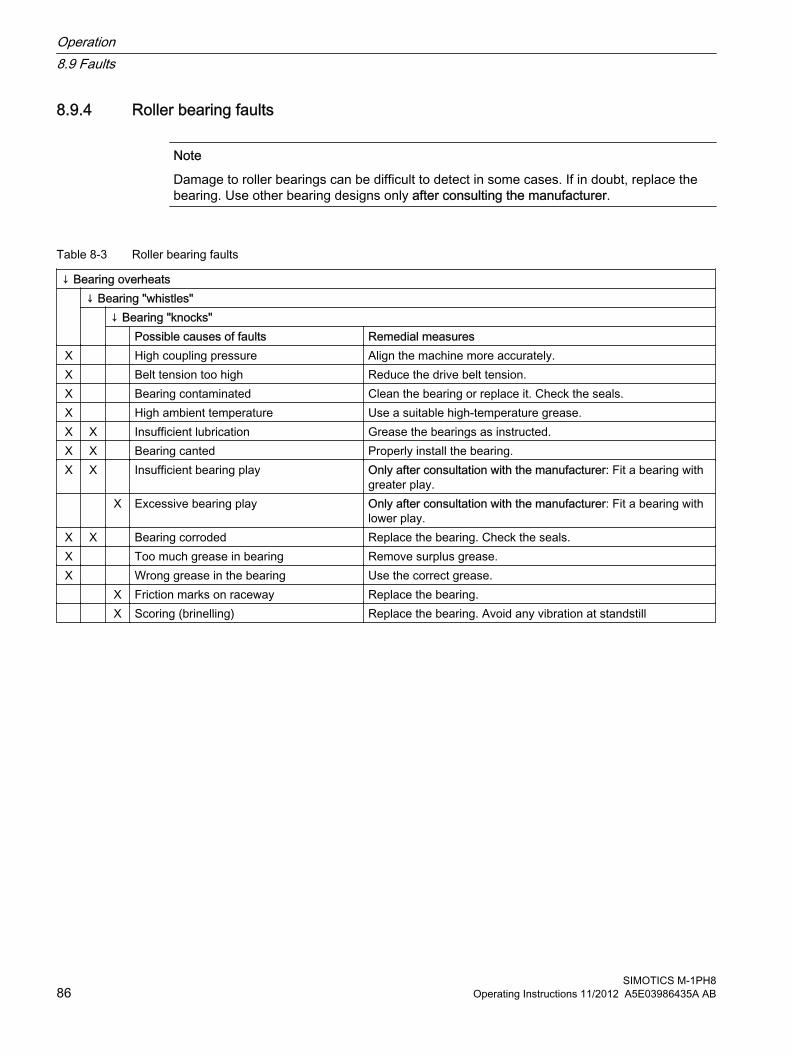
8.9.4 Roller bearing faults
Note
Damage to roller bearings can be difficult to detect in some cases. If in doubt, replace the bearing. Use other bearing designs only after consulting the manufacturer.
Table 8-3 Roller bearing faults
↓ Bearing overheats ↓ Bearing "whistles"
↓ Bearing "knocks" Possible causes of faults Remedial measures
X High coupling pressure Align the machine more accurately.X Belt tension too high Reduce the drive belt tension.X Bearing contaminated Clean the bearing or replace it. Check the seals.X High ambient temperature Use a suitable high-temperature grease.X X Insufficient lubrication Grease the bearings as instructed.X X Bearing canted Properly install the bearing.X X Insufficient bearing play Only after consultation with the manufacturer: Fit a bearing with
greater play. X Excessive bearing play Only after consultation with the manufacturer: Fit a bearing with
lower play.X X Bearing corroded Replace the bearing. Check the seals.X Too much grease in bearing Remove surplus grease.X Wrong grease in the bearing Use the correct grease. X Friction marks on raceway Replace the bearing. X Scoring (brinelling) Replace the bearing. Avoid any vibration at standstill
Operation8.9 Faults
SIMOTICS M-1PH886 Operating Instructions 11/2012 A5E03986435A AB

Maintenance 9
Through careful and regular maintenance, inspections, and overhauls you can detect faults at an early stage and resolve them. This means that you can avoid consequential damage.
Operating conditions and characteristics can vary widely. For this reason, only general maintenance intervals can be specified here. Maintenance intervals should therefore be scheduled to suit the local conditions (dirt, starting frequency, load, etc.).
When carrying out any work on the machine, observe the general safety instructions (Page 13) and the specifications contained in EN 50110‑1 regarding working safely with and on electrical machines.
Comply with the IEC / EN 60079‑17 standard during all servicing and maintenance work on the machine.
NoteService Center
Please contact the Service Center, if you require support with servicing, maintenance or repair.
9.1 Qualified personnelAll work at the machine must be carried out by qualified personnel only. For the purpose of this documentation, qualified personnel is taken to mean people who fulfill the following requirements:
● Through appropriate training and experience, they are able to recognize and avoid risks and potential dangers in their particular field of activity.
● They have been instructed to carry out work on the machine by the appropriate person responsible.
9.2 Observe the operating instructions of the componentsWhen carrying out any maintenance and repair work, always carefully observe the manufacturer's operating instructions for additional components.
See alsoOperating instructions, external fan (Page 146)
SIMOTICS M-1PH8Operating Instructions 11/2012 A5E03986435A AB 87

9.3 Inspection and maintenance
WARNING
Rotating and live parts
Electric machines have live parts and rotating parts. Fatal or serious injuries and substantial material damage can occur if maintenance work is performed on the machine when it is not stopped or not de-energized.● Perform maintenance work on the machine only when it is stopped. The only operation
permissible while the machine is rotating is regreasing the roller bearings.● When performing maintenance work, comply with the five safety rules.
WARNING
Machine damage
If the machine is not maintained it can suffer damage. This can cause faults which can result in eventual or immediate death, serious injury or material damage.
Perform regular maintenance on the machine.
CAUTION
Dust disturbances when working with compressed air
When cleaning with compressed air, dust, metal chips, or cleaning agents can be whirled up. Injuries can result.
When cleaning using compressed air, make sure you use suitable extraction equipment and wear protective equipment (safety goggles, protective suit, etc.).
NOTICE
Damage to insulation
If metal swarf enters the winding head when cleaning with compressed air, this can damage the insulation. Clearance and creepage distances can be undershot. This may cause damage to the machine extending to total failure.
When cleaning with compressed air, ensure there is adequate extraction.
Maintenance9.3 Inspection and maintenance
SIMOTICS M-1PH888 Operating Instructions 11/2012 A5E03986435A AB

NOTICE
Machine damage caused by foreign bodies
Foreign bodies such as dirt, tools or loose components, such as screws etc., can be left by accident inside the machine after maintenance is performed. These can cause short circuits, reduce the performance of the cooling system or increase noise in operation. They can also damage the machine.● When carrying out maintenance work, make sure that no foreign bodies are left in or on
the machine.● Securely attach all loose parts again once you have completed the maintenance
procedures.● Carefully remove any dirt.
Note
Operating conditions and characteristics can vary widely. For this reason, only general intervals for inspection and maintenance measures can be specified here.
WARNING
Explosion hazard due to overheating of the machine caused by a layer of dust
Layers of dust thicker than 5mm can insulate the machine, resulting in overheating. The maximum surface temperature of the machine cannot be adhered to. The dust can ignite, resulting in an explosion. This can result in death, serious injury or material damage.
Dust the machine regularly. Do not allow dust layers thicker than 5 mm to build up on the machine surface. Do not switch the machine on until the dust has been removed.
WARNING
Risk of explosion due to excessive bearing temperature
The surface temperature cannot be maintained within maximum permissible limits if the bearing becomes too hot. The dust can ignite, resulting in an explosion. This can result in death, serious injury or material damage.● Always check the bearing temperature.● In addition to the current-dependent overload protection device located in the three phases
of the connecting cable, we recommend that you also monitor the temperature rise in the motor with the aid of the temperature sensors built into the stator winding.
Maintenance9.3 Inspection and maintenance
SIMOTICS M-1PH8Operating Instructions 11/2012 A5E03986435A AB 89

WARNING
Risk of explosion when cleaning with compressed air
If you clean the machine with compressed air, plastic components may become statically charged and ignite a potentially explosive atmosphere; an explosion can occur. This can result in death, serious injury or material damage.
Do not use compressed air to clean plastic parts in an explosive atmosphere. When cleaning the machine, make sure that the air in the vicinity of the motor is free of gas and dust.
9.3.1 Inspections in the event of faultsNatural disasters or unusual operating conditions, such as overloading or short circuit, are faults that overload the machine electrically or mechanically.
Immediately perform an inspection after such faults.
9.3.2 Initial inspectionPerform the following checks after approximately 500 operating hours or at the latest after six months:
Table 9-1 Checks after installation or repair
Check When the motor is running
At standstill
The electrical parameters are maintained. X The smooth running characteristics and machine running noise have not deteriorated.
X
The motor foundation has no cracks and indentations. (*) X X
(*) You can perform these checks while the motor is running or at a standstill.
Additional checks may also be required according to the system-specific conditions.
NOTICE
If you detect any deviations during the inspection, you must rectify them immediately. They may otherwise damage the motor.
Maintenance9.3 Inspection and maintenance
SIMOTICS M-1PH890 Operating Instructions 11/2012 A5E03986435A AB
9.3.3 General inspection
Inspection intervalPerform the following checks after approx. 16,000 operating hours or two years, whichever comes first.
Implementation● While the motor is running, check that:
– The stated electrical characteristics are being observed
– The smooth running characteristics and machine running noise have not deteriorated
● Once the machine has been shut down, check that:
– The motor foundation has no indentations or cracks
– The machine is aligned within the permissible tolerance ranges
– All the fixing bolts/screws for the mechanical and electrical connections have been securely tightened
– The winding insulation resistances are sufficiently high
– Any bearing insulation has been fitted as shown on plates and labeling.
– Cables and insulating parts and components are in good condition and there is no evidence of discoloring
NOTICE
If you detect any defects or malfunctions during the inspection, you must rectify them immediately. They may otherwise cause damage to the machine.
9.3.4 Rolling-contact bearing inspection
Inspections in the event of faultsPerform an inspection immediately in the event of faults or exceptional operating conditions indicating an electrical or mechanical overload, e.g., overload, short circuit.
Maintenance9.3 Inspection and maintenance
SIMOTICS M-1PH8Operating Instructions 11/2012 A5E03986435A AB 91

Regreasing intervals
NOTICE
Observe the regreasing intervals for the rolling-contact bearings
The regreasing intervals for roller bearings are different from the servicing intervals for the machine. Failure to regrease the rolling-contact bearings at the specified intervals can result in them sustaining damage. Comply with the regreasing intervals for roller bearings, the regreasing intervals are specified on the lubricant plate.
9.3.5 Changing bearings when using permanently lubricated rolling-contact bearingsThe replacement of the permanently lubricated roller bearing is determined by the number of operating hours and is required around every three years.
9.3.6 Maintenance
When carrying out any work on the machine, observe the general safety instructions (Page 13) and the specifications contained in EN 50110‑1 regarding working safely with and on electrical machines.
WARNING
Rotating and live parts
Electric machines have live parts and rotating parts. Fatal or serious injuries and substantial material damage can occur if maintenance work is performed on the machine when it is not stopped or not de-energized.● Perform maintenance work on the machine only when it is stopped. The only operation
permissible while the machine is rotating is regreasing the roller bearings.● When performing maintenance work, comply with the five safety rules (Page 13).
WARNING
Machine damage
If the machine is not maintained it can suffer damage. This can cause faults which can result in eventual or immediate death, serious injury or material damage.
Perform regular maintenance on the machine.
Maintenance9.3 Inspection and maintenance
SIMOTICS M-1PH892 Operating Instructions 11/2012 A5E03986435A AB

CAUTION
Dust disturbances when working with compressed air
When cleaning with compressed air, dust, metal chips, or cleaning agents can be whirled up. Injuries can result.
When cleaning using compressed air, make sure you use suitable extraction equipment and wear protective equipment (safety goggles, protective suit, etc.).
NOTICE
Damage to insulation
If metal swarf enters the winding head when cleaning with compressed air, this can damage the insulation. Clearance and creepage distances can be undershot. This may cause damage to the machine extending to total failure.
When cleaning with compressed air, ensure there is adequate extraction.
NOTICE
Machine damage caused by foreign bodies
Foreign bodies such as dirt, tools or loose components, such as screws etc., can be left by accident inside the machine after maintenance is performed. These can cause short circuits, reduce the performance of the cooling system or increase noise in operation. They can also damage the machine.● When carrying out maintenance work, make sure that no foreign bodies are left in or on
the machine.● Securely attach all loose parts again once you have completed the maintenance
procedures.● Carefully remove any dirt.
Note
Operating conditions and characteristics can vary widely. For this reason, only general intervals for inspection and maintenance measures can be specified here.
WARNING
Risk of explosion when cleaning with compressed air
If you clean the machine with compressed air, plastic components may become statically charged and ignite a potentially explosive atmosphere; an explosion can occur. This can result in death, serious injury or material damage.
Do not use compressed air to clean plastic parts in an explosive atmosphere. When cleaning the machine, make sure that the air in the vicinity of the motor is free of gas and dust.
Maintenance9.3 Inspection and maintenance
SIMOTICS M-1PH8Operating Instructions 11/2012 A5E03986435A AB 93
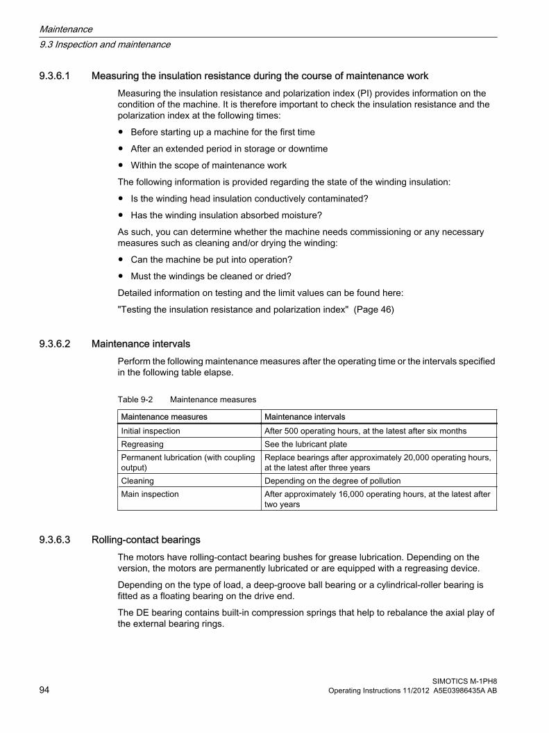
9.3.6.1 Measuring the insulation resistance during the course of maintenance workMeasuring the insulation resistance and polarization index (PI) provides information on the condition of the machine. It is therefore important to check the insulation resistance and the polarization index at the following times:
● Before starting up a machine for the first time
● After an extended period in storage or downtime
● Within the scope of maintenance work
The following information is provided regarding the state of the winding insulation:
● Is the winding head insulation conductively contaminated?
● Has the winding insulation absorbed moisture?
As such, you can determine whether the machine needs commissioning or any necessary measures such as cleaning and/or drying the winding:
● Can the machine be put into operation?
● Must the windings be cleaned or dried?
Detailed information on testing and the limit values can be found here:
"Testing the insulation resistance and polarization index" (Page 46)
9.3.6.2 Maintenance intervalsPerform the following maintenance measures after the operating time or the intervals specified in the following table elapse.
Table 9-2 Maintenance measures
Maintenance measures Maintenance intervalsInitial inspection After 500 operating hours, at the latest after six monthsRegreasing See the lubricant platePermanent lubrication (with coupling output)
Replace bearings after approximately 20,000 operating hours, at the latest after three years
Cleaning Depending on the degree of pollution Main inspection After approximately 16,000 operating hours, at the latest after
two years
9.3.6.3 Rolling-contact bearingsThe motors have rolling-contact bearing bushes for grease lubrication. Depending on the version, the motors are permanently lubricated or are equipped with a regreasing device.
Depending on the type of load, a deep-groove ball bearing or a cylindrical-roller bearing is fitted as a floating bearing on the drive end.
The DE bearing contains built-in compression springs that help to rebalance the axial play of the external bearing rings.
Maintenance9.3 Inspection and maintenance
SIMOTICS M-1PH894 Operating Instructions 11/2012 A5E03986435A AB

See alsoDescription (Page 21)
9.3.6.4 LubricationThe specified grease data apply for the data specified on the rating plate data and for high-quality grease in accordance with the specifications in these operating instructions. These greases significantly exceed the requirements according to DIN 51825 and ISO 6743‑9, thereby permitting the specified relubrication intervals.
Initial lubricationFor initial lubrication of the bearings (when delivered), the lubricating grease ESSO / Unirex N (standard version) or Lubcon / Sintono GPE702 (Performance version) is used.
Grease selection criteriaHigh qualityISO‑L‑X BDEA3 grease according to ISO 6743-9 and K3N‑20 grease according to DIN 51825 with lithium soap as a thickener and an upper service temperature of at least+140 °C / +284 °F are permissible for standard applications without special requirements.
When selecting the lubricating grease, ensure that the technical data of the grease is suitable for the application.
The lubricating grease must satisfy the criteria listed in the table below and must match the operating conditions.
Table 9-3 Criteria for selecting roller bearing greases
Criteria Standard Property, characteristic value UnitType of base oil - Mineral oil -Thickener - Lithium -Consistency according to NLGI class DIN 51818 ● 3 for vertical and horizontal types of construction
● 2 alternatively for horizontal type of construction with reduced lubrication interval
-
Worked penetration DIN ISO 2137 220–295 0.1 mmOperating temperature range - At least -20 °C ... +140 °C °CDropping point DIN ISO 2176 At least +200 °C °CBasic oil viscosity DIN 51562-1 ● Approx. 100 mm²/s at 40 °C
● Approx. 10 mm²/s at 100 °Cmm²/s
Additive - ● Antioxidation (AO), Anti-Wear (AW)● No solid lubricants● Alternative: Extreme-pressure (EP) only after
consultation with grease and bearing manufacturers
-
FE9 test: A/1500/6000 DIN 51821-1/-2 F10 ≥ 50 h at +140 °CF50 ≥ 100 h at +140 °C
h
Behavior with respect to water DIN 51807 0 or 1 at a test temperature of +90 °C -Corrosive effect on copper DIN 51811 0 or 1 at a test temperature of +140 °C Corr.°
Maintenance9.3 Inspection and maintenance
SIMOTICS M-1PH8Operating Instructions 11/2012 A5E03986435A AB 95

Criteria Standard Property, characteristic value UnitResistance to corrosion (EMCOR) DIN 51802 /
ISO 110070 - 0 (0 - 1, permissible for special greases) Corr.°
Solid matter content, particle sizes > 25 μm
DIN 51813 < 10 mg/kg mg/kg
Suitability of bearingsSpeed characteristic nxdm
- Suitable for the built-in motor bearings, seals and these speeds
-mm/min
If different special lubricating greases are stated on the lubricant plate, then different criteria apply.
NOTICE
Other ambient temperatures and operating conditions
For other ambient temperatures and operating conditions, an alternative grease to the one stated on the lubricant plate may only be used after prior consultation with the manufacturer. Otherwise the roller bearing could be damaged.
NOTICE
Use of other greases
If other greases are used, there can be no guarantee of compatibility with the overall system. Otherwise the roller bearing could be damaged.
If you use greases that satisfy only the minimum requirements of DIN 51825 or ISO 6743-9, then reduce the lubrication intervals by half or adapt them accordingly. If in doubt, consult the manufacturer.
Recommended greases for roller bearingsFor standard applications, the following high-quality greases are recommended for roller bearings for vertical and horizontal motor types of construction due to their technical properties:
Table 9-4 Roller bearing greases for vertical and horizontal types of construction
Manufacturer Grease typeExxonMobil Unirex N3EssoFuchs Renolit H443 HD88Lubcon Turmoplex 3FAG Arcanol Multi 3
For motors with a horizontal type of construction, you can alternatively use greases with NLGI Class 2. However, this reduces the lubrication interval by 20 %.
Table 9-5 Alternative greases with NLGI Class 2 for motors with a horizontal type of construction
Manufacturer Grease typeExxonMobil Unirex N2Esso
Maintenance9.3 Inspection and maintenance
SIMOTICS M-1PH896 Operating Instructions 11/2012 A5E03986435A AB
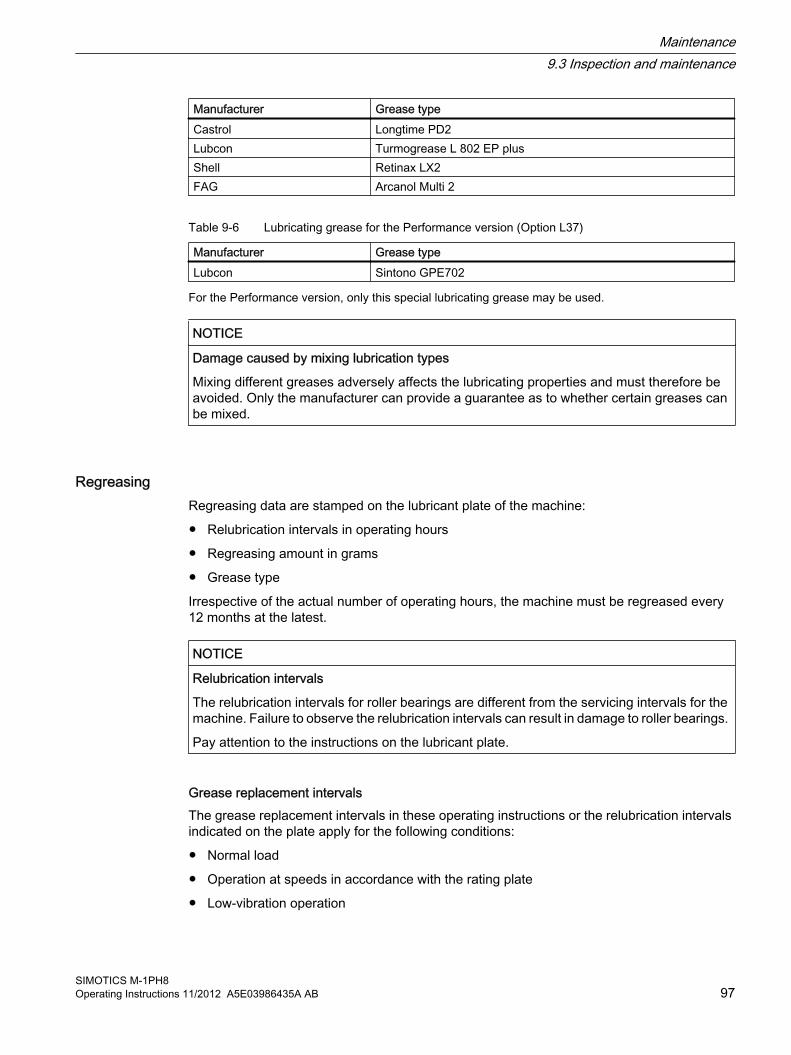
Manufacturer Grease typeCastrol Longtime PD2Lubcon Turmogrease L 802 EP plusShell Retinax LX2FAG Arcanol Multi 2
Table 9-6 Lubricating grease for the Performance version (Option L37)
Manufacturer Grease typeLubcon Sintono GPE702
For the Performance version, only this special lubricating grease may be used.
NOTICE
Damage caused by mixing lubrication types
Mixing different greases adversely affects the lubricating properties and must therefore be avoided. Only the manufacturer can provide a guarantee as to whether certain greases can be mixed.
RegreasingRegreasing data are stamped on the lubricant plate of the machine:
● Relubrication intervals in operating hours
● Regreasing amount in grams
● Grease type
Irrespective of the actual number of operating hours, the machine must be regreased every 12 months at the latest.
NOTICE
Relubrication intervals
The relubrication intervals for roller bearings are different from the servicing intervals for the machine. Failure to observe the relubrication intervals can result in damage to roller bearings.
Pay attention to the instructions on the lubricant plate.
Grease replacement intervalsThe grease replacement intervals in these operating instructions or the relubrication intervals indicated on the plate apply for the following conditions:
● Normal load
● Operation at speeds in accordance with the rating plate
● Low-vibration operation
Maintenance9.3 Inspection and maintenance
SIMOTICS M-1PH8Operating Instructions 11/2012 A5E03986435A AB 97

● Neutral ambient air
● High-quality roller bearing greases
In the case of unfavorable operating conditions, the relubrication intervals must be reduced after consultation with the manufacturer.
Regreasing The shaft must rotate during regreasing, so that the new grease can be distributed throughout the bearing. For motors that are be operated with a converter, regreasing should be carried out at low-to-medium speed where possible (nmin = 250 rpm, nmax = 3600 rpm) to ensure an even distribution of grease.
WARNING
Rotating parts
When regreasing, pay attention to all rotating components. This can result in death, serious injury or material damage.
Clean the grease nipples before regreasing and then gradually press in an appropriate type and amount of grease, as described on the lubricant plate and by the specifications in these Operating Instructions.
The roller bearing temperature rises sharply at first, then drops to the normal value again after the excess grease has being expelled from the bearing.
The used grease collects outside each bearing in a spent grease chamber. If the specifications on the lubricant plate are observed, the spent grease chamber will provide capacity for a calculated service life of at least 20 000 operating hours (approx. 2.5 years).
Maintenance9.3 Inspection and maintenance
SIMOTICS M-1PH898 Operating Instructions 11/2012 A5E03986435A AB

Lubricating using the regreasing system A flat grease nipple in accordance with DIN 3404, size M10x1, is provided at both the DE ① and the NDE ② for regreasing.
1. Clean the grease nipples at the DE and NDE.
2. Press in the type and quantity of grease specified (see lubrication instruction plate). The shaft should rotate so that the new grease can be distributed throughout the bearing.The bearing temperature rises sharply at first, then drops to the normal value again after the excess grease has been displaced out of the bearing.
Figure 9-1 Flat grease nipples ① and ② (schematic representation for types 1PH818. and 1PH822.)
WARNING
Overheating of the rolling bearings
If the roller bearings are not regularly regreased, local overheating may be possible, and, as a consequence, an explosion in an explosive atmosphere. This can result in death, serious injury or material damage.● Regrease the roller bearings regularly according to the lubrication plate.● Implement bearing temperature monitoring if not yet in existence.
9.3.6.5 Cleaning the spent grease chamberThe rolling-contact bearing's spent grease chamber only has room for a limited amount of spent grease. When the spent grease chamber is full, the spent grease must be removed, otherwise it will penetrate into the interior of the machine. The information on the amount of grease to be used when regreasing can be found on the lubricant plate. When changing the
Maintenance9.3 Inspection and maintenance
SIMOTICS M-1PH8Operating Instructions 11/2012 A5E03986435A AB 99

bearings remove the spent grease that has collected in the spent grease chamber and in the outer bearing cover.
To remove the spent grease, proceed as follows:
1. Remove the transmission element.
2. Remove the spent grease:
– At the DE, unscrew the outer bearing cover and empty the spent grease from the outer bearing cover.
– At the NDE, remove the cover of the speed sensor and the cover of the spent grease chamber. Empty the spent grease chamber.
Note
For types 1PH818. and 1PH822., you must remove the fan before removing the speed encoder cover. At the NDE, remove the fan and then the speed encoder cover.
Maintenance9.3 Inspection and maintenance
SIMOTICS M-1PH8100 Operating Instructions 11/2012 A5E03986435A AB
9.3.6.6 Cleaning the cooling air passages
Cleaning the cooling air passages ● Regularly clean the cooling air passages through which the ambient air flows, e.g. using
dry compressed air.
NOTICE
Cleaning intervals depend on the degree of fouling
The frequency of the cleaning intervals depends on the local degree of fouling. The machine can overheat if the cooling air passages are fouled and the cooling air cannot flow without obstruction.
Check for fouling regularly and clean the cooling air passages through which the ambient air flows.
Servicing the external fan● Check the external fan in accordance with DIN ISO 10816 every 12 months for mechanical
vibrations. The maximum permissible vibrational severity is 2.8 mm/s measured on the end shield of the impeller-side motor bearing.
● Regularly clean and inspect the fan. Impeller and frame are subject to natural wear depending on the area of application and displacement medium.
WARNING
Impeller can crack
Due to deposits and the resulting imbalance there is a hazard of fatigue fracture of the impeller. The impeller can crack in operation. Death, serious injury, or material damage can result.
Regularly clean and inspect the fan.
Maintenance9.3 Inspection and maintenance
SIMOTICS M-1PH8Operating Instructions 11/2012 A5E03986435A AB 101

WARNING
Voltages at the internal motor connections
The motor may continue running, e.g. due to airflow, or may run on after being shut down. This means that dangerous voltages of over 50 V can occur at the internal motor connections. Death, serious injury, or material damage can result.● For safety reasons, it is not permissible to make any unauthorized modifications or
changes to the fan.● Due to the way it functions, the fan switches on and off automatically.● After a power failure or when the power has been disconnected, the fan starts up
automatically again when the voltage is restored.● Wait until the fan has come to a standstill before approaching it.● Provide a protective circuit that prevents the main motor from being switched on when
the external fan is not in operation.
Cleaning the fanIf the fan blades need to be cleaned, the following points must be observed:
DANGER
Danger of shearing
During maintenance work on the forced ventilation unit (e.g. when cleaning the fan blades), the fan must be at a standstill. The circuit for the forced ventilation unit must be open and a safeguard must be provided to prevent unintentional reclosing.
CAUTION
Avoid the effects of excessive force
If excessive forces are present, this can damage the fan blades.
The fan should be cleaned with a suitable cloth or brush, and steps should be taken to prevent moisture from entering the motor.
● Once the voltage has been disconnected on all poles, wait for five minutes before touching the device.
● Never open the device during operation.
● Never loosen any fixing screws for the ventilation unit during operation.
Maintenance9.3 Inspection and maintenance
SIMOTICS M-1PH8102 Operating Instructions 11/2012 A5E03986435A AB

Changing the filter mat of the external fan (option)Check the state of the filter mat regularly depending on the prevailing conditions. Change it if it is dirty.
CAUTION
Changing the filter only when the fan is stationary
When the mesh is removed, the degree of protection is no longer guaranteed. There is a risk of injury. Only change the filter when the fan is stationary.
1. Unscrew the fan guard and remove the old filter mat.
2. Insert the new filter mats and screw the fan guard back into position.
You can order the filter mat as a spare part.
● Spare parts, external fan (Page 114)
● Spare parts kits (Page 111)
● Ordering spare parts via the Internet (Page 112)
9.3.6.7 Maintaining terminal boxes
RequirementThe machine is de-energized.
Checking the terminal box● Terminal boxes must be regularly checked for tightness, undamaged insulation, and tight
terminal connections.
● If dust or humidity have infiltrated the terminal box, this should be cleaned and dried (particularly the insulators).Check all the seals and sealing surfaces and address the cause of the leakiness.
● Check the insulators, connectors and cable connections in the terminal box.
● Replace the damaged components if necessary.
WARNING
Short-circuit hazard
Damaged components can cause short circuits, possibly resulting in death, serious injuries and property damage.
Replace damaged components.
Maintenance9.3 Inspection and maintenance
SIMOTICS M-1PH8Operating Instructions 11/2012 A5E03986435A AB 103

9.4 Repair
When carrying out any work on the machine, observe the general safety instructions (Page 13) and the specifications contained in EN 50110‑1 regarding working safely with and on electrical machines.
WARNING
Explosion hazard when carrying out repair work
Repairs are only permissible within the scope of the work described in these operating instructions. Otherwise an explosion can occur in an explosive atmosphere. This can result in death, serious injury or material damage.
For repairs to go beyond this scope, please contact the Service Center.
Comply with the IEC / EN 60079‑17 standard during all servicing and maintenance work on the machine.
Note
If the motor has to be transported, please observe the information and instructions in the "Transport" (Page 35) section.
9.4.1 Prepare servicing work● The drawings and parts lists do not contain any detailed information about the type and
dimensions of fixing elements and components. For this reason, you should establish this information when dismantling them and make a note of it for the purpose of reassembly.
● Document the type, dimensions and arrangement of the parts so that you will be able to reassemble the machine to its original state.
● Use suitable tools to disassemble the machine.
● Take measures to prevent parts from dropping down before you dismantle them, e.g. by replacing fastening elements with extra-long screws, threaded bolts or similar. This ensures that the part is supported after it is pulled off.
● The centerings in the shaft extensions have reset threads. Use lifting gear which is suitable for the rotor weight and direction of loading.
Maintenance9.4 Repair
SIMOTICS M-1PH8104 Operating Instructions 11/2012 A5E03986435A AB

WARNING
Rotor can fall down
Eyebolts in accordance with DIN 580 are unsuitable for suspending the rotor. The rotor can fall off. This can result in death, serious injury or material damage.
Use lifting gear which is suitable for the rotor weight and direction of loading.
WARNING
Machine damage caused by improper repair work
Improper servicing work can damage the machine. This can cause damages and/or faults which can result in eventual or immediate death, serious injury, or property damage.● Properly assemble or disassemble the machine.● Use only suitable tools and equipment.● Immediately replace damaged components.● Contact the Service Center, if necessary.
9.4.2 Explosion hazard during installation and disassembling of the external fan
WARNING
Explosion hazard
Sparks can occur if the external fan rotor grazes the external fan housing and ignite ambient air dust. An explosion can result. This can result in death, serious injury or material damage.
The external fan may only by removed and installed by appropriately qualified technical personnel or a Siemens Service workshop. Only then can it be ensured that the distance between the external fan rotor and the external fan housing is greater than 2 mm.
Maintenance9.4 Repair
SIMOTICS M-1PH8Operating Instructions 11/2012 A5E03986435A AB 105

9.4.3 Disassembling the machineThe drawings and parts lists do not contain any detailed information about the type and dimensions of fixing elements, etc.
NOTICE
Installing and removing the impeller
For some motor versions the stator link has an interior diameter that is smaller than the impeller diameter. When removing the rotor the stator coil connection can be damaged.
Only install the impeller in the direction on which a stator link is not attached. Contact the Siemens Service Center (Page 125), if necessary.
NOTICE
Dismantling centered parts
Centered parts can be damaged if dismantled improperly with unsuitable tools.
Use pullers or suitable devices to disassemble parts and components attached to the motor shaft.
Removing1. Ensure you do not damage insulation when dismantling the device. Check the insulation
for possible damage prior to re-installing.
2. To disassemble the motor, disconnect the connecting cables from the terminals and the entry plate from the terminal box housing.In this way, the respective positioning of the cables in relation to one another and the sealing of the cables in the cable entries are to a large extent maintained.
3. Remove the connecting cables in the terminal box of the fan motor, and if necessary the cable on the ground terminal and the cables laid out on the motor.
4. Pull out the connector of the speed sensor.
LinksThe circuit diagram (Page 59) shows the relationships required when connecting to the line supply.
Component assignmentWhen dismantling or assembling the bearing pay attention to the proper arrangement of the components particularly if the bearing is the same size on the DE side and NDE side, for example:
● Bearing shield
● Bearings
● Compression springs
Maintenance9.4 Repair
SIMOTICS M-1PH8106 Operating Instructions 11/2012 A5E03986435A AB

● Spacer washers,
● Covers with different centering length, etc.
Insulated roller bearingsIf roller-contact bearings with an insulated design are installed, use roller bearings of the same type as spare parts. This will prevent any bearing damage being caused by bearing currents.
9.4.4 Removing and installing the protecting ringThe protecting ring acts as an outer bearing seal. It sits on the shaft outside the bearing end shield.
Maintenance9.4 Repair
SIMOTICS M-1PH8Operating Instructions 11/2012 A5E03986435A AB 107

Disassembly● Once the coupling is detached, you can remove the protective ring from the shaft. After it
has been removed, the protective ring will be deformed and must be replaced.
Assembly● Push the protecting ring over the end of the shaft. Make sure that the outer collar is placed
at a spacing of 1 mm from the bearing end shield.
Figure 9-2 Fitting the protecting ring
9.4.5 Removing and mounting the bearing shields1. Unscrew the belt pulleys. The belt pulleys may be jammed or distorted, in which case you
should lever them off carefully.
2. Remove the bearing shield.When removing the bearing shields, take care that the windings are not damaged.
For assembly, proceed in reverse order.
9.4.6 Installing the machineStrictly ensure the greatest possible care and cleanliness when repairing the machine.
Maintenance9.4 Repair
SIMOTICS M-1PH8108 Operating Instructions 11/2012 A5E03986435A AB
Mount the machine on an alignment plate. This ensures that the contact surfaces of the motor feet are all on the same level.
NOTICE
Do not damage windings
Windings protrude from the stator housing and can be damaged when attaching the end shield. This can damage the motor.
When mounting the end shield, ensure that the windings that project from the stator housing are not damaged.
Sealing the motor● Clean bare joints between parts before re-assembling (e.g. between enclosures, end
shields and the active parts of bearings).
● Brush the bare joints with the non-hardening sealing agent " Hylomar M".
● Note that these joints between parts (e.g. the sealing gap on the active part of the bearing) must also be resealed with a suitable, silicone-free sealant during assembly.
● Check the sealing elements fitted (e.g. at the terminal boxes) and replace them if they do not provide an adequate seal.
● Follow the manufacturer's application and safety instructions when using the sealant.
● Replace parts that are subject to wear such as the adjusting springs.
Installing the active parts of the bearings 1. First position the parts that must be arranged on the shaft within the bearing.
2. To fit the bearings on the shaft, heat them up to about 80 °C in oil or air.
3. Then push the bearings onto the shaft up to its shoulder. Avoid any heavy blows that might damage the bearings.
4. Fill the bearing to the top with the specified lubricating grease.
9.4.7 Removing the external fanThe external fan may only be replaced, removed and mounted by qualified technical personnel or a Siemens Service Center.
9.4.8 Removing and mounting the speed encoderThe speed encoder may only be replaced, removed and mounted by qualified technical personnel or a Siemens Service Center.
Maintenance9.4 Repair
SIMOTICS M-1PH8Operating Instructions 11/2012 A5E03986435A AB 109

9.4.9 Touch up any damaged paintworkIf the paint is damaged, it must be repaired in order to protect the unit against corrosion.
NotePaint system
Contact the Service Center before you repair any paint damage. They will provide you with more information about the correct paint system and methods of repairing paint damage.
WARNING
Repainting explosion-proof motors
The paint coat can become electrostatically charged where there is a thick coat. Electrostatic discharges can occur. There is a risk of explosion if potentially explosive mixtures are also present at this moment. This can result in death, serious injury or material damage.
You must comply with one of the following requirements when you repaint painted surfaces:
● Limit the surface resistance of the paint used:Surface resistance ≤ 1 GΩ for motors of explosion group III
● Breakdown voltage ≤ 4 kV for explosion group III
Suitability test of the paint system for hazardous areas Proof is available for the electrostatic suitability with explosion-proof machines for the paint systems ordered by default. Such evidence is not available for paint systems that are non-standard or specifically requested by customers. Take into consideration that the provided evidence is not valid for repaintings.
Maintenance9.4 Repair
SIMOTICS M-1PH8110 Operating Instructions 11/2012 A5E03986435A AB

Spare parts 1010.1 Ordering data
When ordering spare parts, in addition to the precise designation of the spare part, specify the motor type and the serial number of the motor. Ensure that the spare part designation matches the designation in the spare part lists and add the associated part number.
Example:
Spare part Spare parts kit, drive-end bearing (Part 3.00)Machine type 1PH81841JD202FA1Serial number N-W91246206010001
The machine type and the serial number are indicated on the rating plate and in the technical data, and are also embossed on the drive end of the shaft.
NoteBar code on rating plate
You can also read the machine type and serial number from the bar code on the rating plate.
Note
The graphics in this chapter are schematic representations of the basic versions. They are used for spare parts definitions. The supplied version may differ in details from these representations.
10.2 Spare parts kitsThe spare parts are bundled with the necessary wearing parts in a logical way so as to create spare parts kits. The spare parts kits for the bearings also contain the bearing grease.
The following spare parts kits are available for you to order:
3.00 Spare parts kit, non-drive-end bearing (complete)4.00 Spare parts kit, drive-end bearing (complete)32.00 Spare parts kit, separately driven fan (only force-ventilated motors)55.00 Spare parts kit, relevant version of speed encoder
Additional spare parts are available on request.
For an overview of the services available from Technical Support, please visit:
Technical Support (http://support.automation.siemens.com/WW/view/en/16605654)
SIMOTICS M-1PH8Operating Instructions 11/2012 A5E03986435A AB 111

If you wish to submit a service request directly, you can do so via the following page:
http://www.siemens.com/automation/support-request (http://www.siemens.com/automation/support-request)
Insulated roller bearingsIf roller-contact bearings with an insulated design are installed, use roller bearings of the same type as spare parts. This will prevent any bearing damage being caused by bearing currents.
10.3 Ordering spare parts via the InternetSpare parts can be ordered online from the spare parts service "Spares on Web":
Spares on Web (https://b2b-extern.automation.siemens.com/spares_on_web).
You can use "Spares on Web" to determine the order numbers for motor spare parts quickly and easily.
A short description of how to use "Spares on Web" is available on the Internet.
Guide for Spares on Web (http://support.automation.siemens.com/WW/news/en/25248626).
10.4 Using commercially available spare parts
WARNING
Risk of explosion
If you use parts other than the original spare parts, the type of protection can no longer be guaranteed. This can result in an explosion during operation in a potentially explosive gaseous atmosphere. This can result in death, serious injury or material damage.● Use only original spare parts for explosion-proof machines; this also applies to
components such as seals, terminals, cables and cable entries. Should you have any questions, please contact the Service Center .
● Commercially available equivalent standard parts such as screws may be used.
Spare parts10.4 Using commercially available spare parts
SIMOTICS M-1PH8112 Operating Instructions 11/2012 A5E03986435A AB

10.5 Spare parts force-ventilated motor
10.5.1 Force-ventilated motor, complete
Figure 10-1 Schematic representation of the motor, complete
Table 10-1 Motor, complete
Number Designation Number Designation3.00 Spare parts kit, NDE bearing 10.00* Stator housing (with laminated core
and winding)4.00 Spare parts kit, DE bearing 10.35* Eyebolt5.00* Bearing shield, DE 20.00* Terminal box6.00* Bearing shield, NDE 32.00 External fan8.00* Rotor, complete 55.10 Spare parts kit, speed encoder
* On request
Spare parts10.5 Spare parts force-ventilated motor
SIMOTICS M-1PH8Operating Instructions 11/2012 A5E03986435A AB 113
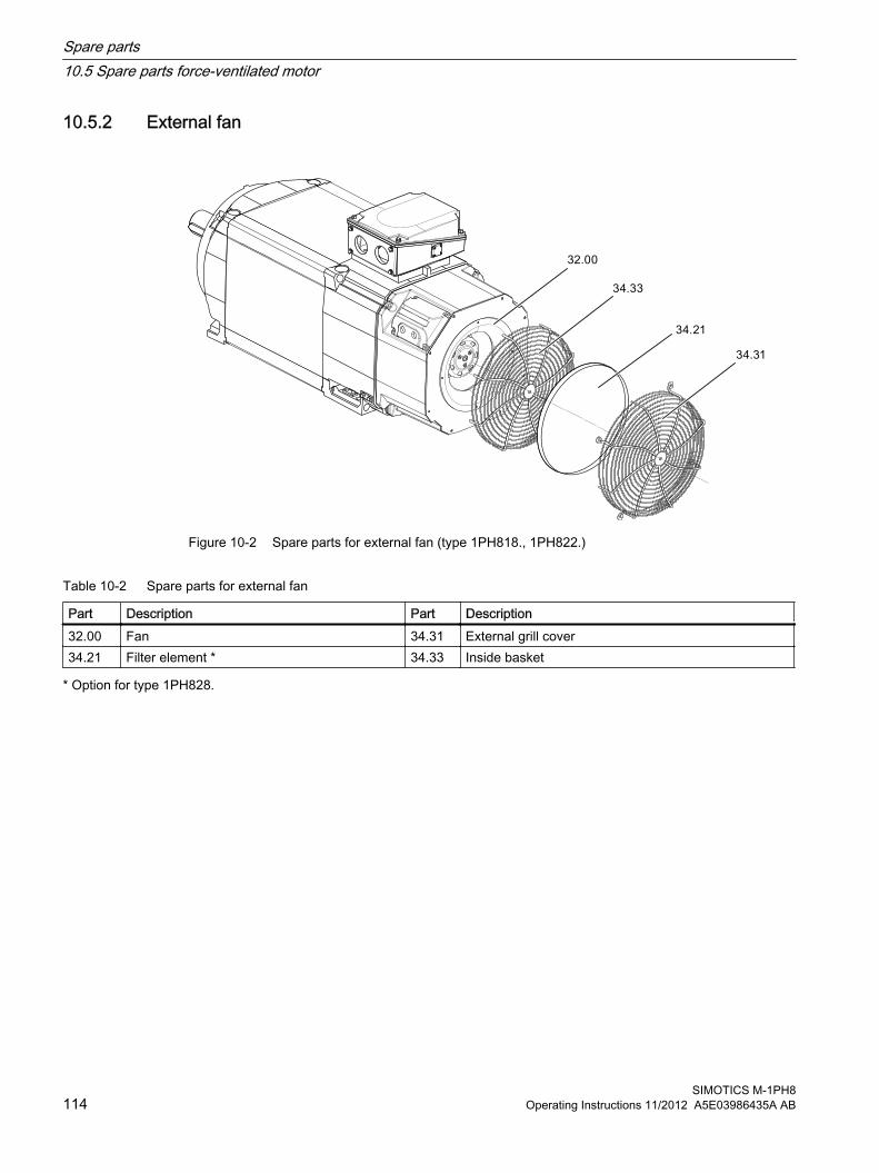
10.5.2 External fan
Figure 10-2 Spare parts for external fan (type 1PH818., 1PH822.)
Table 10-2 Spare parts for external fan
Part Description Part Description32.00 Fan 34.31 External grill cover34.21 Filter element * 34.33 Inside basket
* Option for type 1PH828.
Spare parts10.5 Spare parts force-ventilated motor
SIMOTICS M-1PH8114 Operating Instructions 11/2012 A5E03986435A AB

10.5.3 Roller bearing cartridge DE with radial shaft sealing ring with regreasing
Figure 10-3 Rolling-contact bearing bush drive end with mounted gearing, with regreasing
Table 10-3 Spare parts for rolling-contact bearing bush drive end with mounted gearing, with regreasing
Number Designation Number Designation3.00 Spare parts kit, drive-end bearing
● Deep-groove ball bearing (floating bearing)
● Radial shaft sealing ring ● Inner ring
3.60* Inner bearing cover
3.20* Outer bearing cover 3.80* Grease nipple3.45* Corrugated spring/compression
springs
* On request
Spare parts10.5 Spare parts force-ventilated motor
SIMOTICS M-1PH8Operating Instructions 11/2012 A5E03986435A AB 115

10.5.4 Roller bearing cartridge DE, belt coupling
Figure 10-4 Rolling-contact bearing bush drive end with belt coupling, with regreasing
Table 10-4 Spare parts for rolling-contact bearing bush drive end with belt coupling, with regreasing
Number Designation Number Designation3.00 Spare parts kit, drive-end bearing
● Cylindrical-roller bearing (floating bearing)
● Protecting ring (rotating)
3.60* Inner bearing cover
3.20* Outer bearing cover 3.80* Grease nipple
* On request
Spare parts10.5 Spare parts force-ventilated motor
SIMOTICS M-1PH8116 Operating Instructions 11/2012 A5E03986435A AB
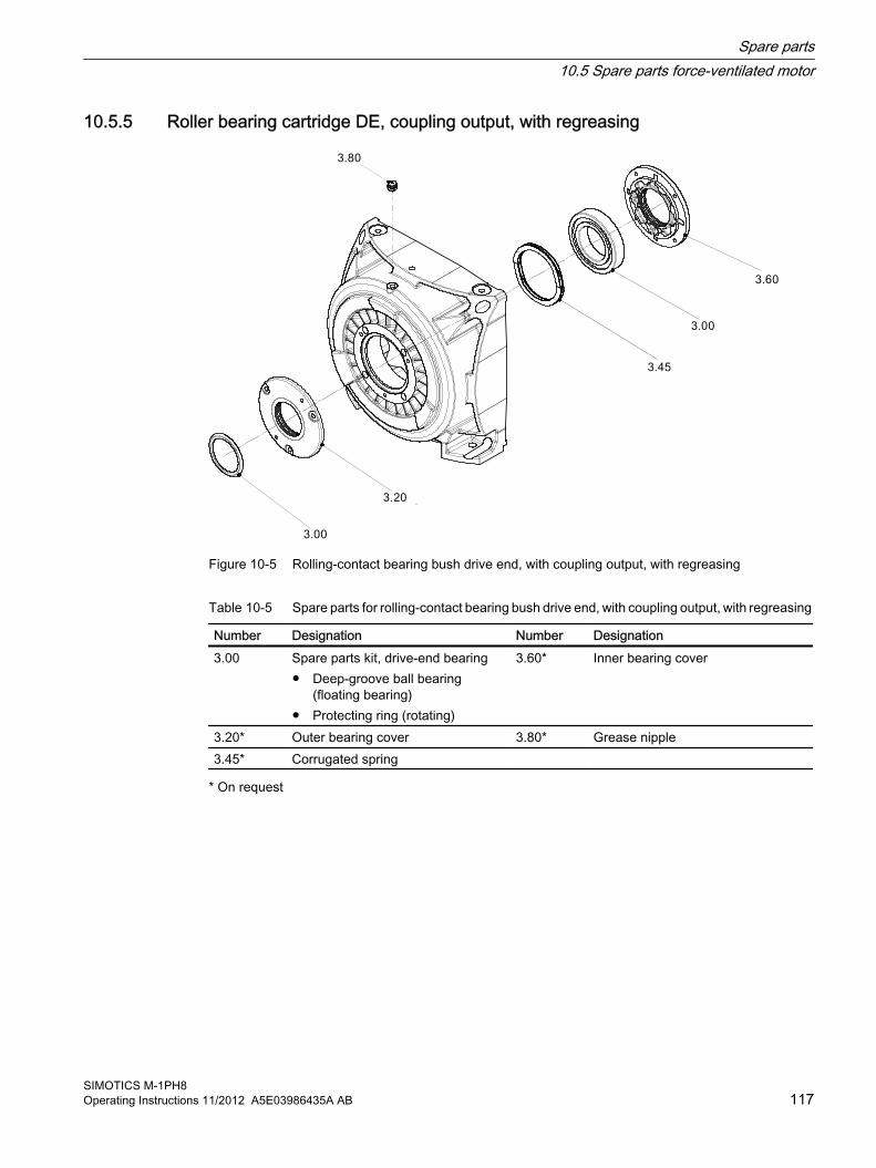
10.5.5 Roller bearing cartridge DE, coupling output, with regreasing
Figure 10-5 Rolling-contact bearing bush drive end, with coupling output, with regreasing
Table 10-5 Spare parts for rolling-contact bearing bush drive end, with coupling output, with regreasing
Number Designation Number Designation3.00 Spare parts kit, drive-end bearing
● Deep-groove ball bearing (floating bearing)
● Protecting ring (rotating)
3.60* Inner bearing cover
3.20* Outer bearing cover 3.80* Grease nipple3.45* Corrugated spring
* On request
Spare parts10.5 Spare parts force-ventilated motor
SIMOTICS M-1PH8Operating Instructions 11/2012 A5E03986435A AB 117

10.5.6 Roller bearing cartridge DE, coupling output, with permanent lubrication
Figure 10-6 Rolling-contact bearing bush drive end, with coupling output, with permanent lubrication
Table 10-6 Spare parts for rolling-contact bearing bush drive end, with coupling output, with permanent lubrication
Number Designation3.00 Spare parts kit, drive-end bearing
● Deep-groove ball bearing (floating bearing)● Protecting ring (rotating)
3.45* Corrugated spring/compression springs
* On request
Spare parts10.5 Spare parts force-ventilated motor
SIMOTICS M-1PH8118 Operating Instructions 11/2012 A5E03986435A AB

10.5.7 Roller bearing cartridge NDE, with permanent lubrication
Figure 10-7 Roller bearing cartridge, non-drive end, permanent lubrication
Table 10-7 Spare parts for roller bearing cartridge, non-drive end, permanent lubrication
Number Designation4.00 Spare parts kit, NDE bearing
● Deep-groove ball bearing (locating bearing)● Retaining ring
4.60* Inner bearing cover
* On request
Spare parts10.5 Spare parts force-ventilated motor
SIMOTICS M-1PH8Operating Instructions 11/2012 A5E03986435A AB 119
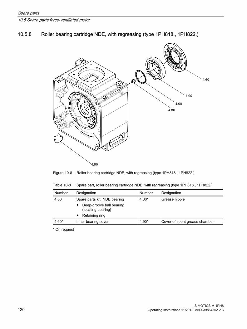
10.5.8 Roller bearing cartridge NDE, with regreasing (type 1PH818., 1PH822.)
Figure 10-8 Roller bearing cartridge NDE, with regreasing (type 1PH818., 1PH822.)
Table 10-8 Spare part, roller bearing cartridge NDE, with regreasing (type 1PH818., 1PH822.)
Number Designation Number Designation4.00 Spare parts kit, NDE bearing
● Deep-groove ball bearing (locating bearing)
● Retaining ring
4.80* Grease nipple
4.60* Inner bearing cover 4.90* Cover of spent grease chamber
* On request
Spare parts10.5 Spare parts force-ventilated motor
SIMOTICS M-1PH8120 Operating Instructions 11/2012 A5E03986435A AB

10.6 Terminal box
Figure 10-9 Terminal box
Table 10-9 Spare parts for terminal box
Number Designation Number Designation20.20* Enclosure 20.50* Entry plate20.30* Cover 20.60* Adapter plate (optional)
* On request
Spare parts10.6 Terminal box
SIMOTICS M-1PH8Operating Instructions 11/2012 A5E03986435A AB 121

10.7 Speed encoder (type 1PH818., 1PH822.)
Figure 10-10 Speed encoder
Table 10-10 Spare part, speed encoder (type 1PH818., 1PH822.)
Part Description55.00 Spare parts kit, speed encoder
● Speed encoder● Torque arm
6.80* Cover
* On request
Spare parts10.7 Speed encoder (type 1PH818., 1PH822.)
SIMOTICS M-1PH8122 Operating Instructions 11/2012 A5E03986435A AB

Disposal 1111.1 Introduction
Protecting the environment and preserving its resources are corporate goals of the highest priority for us. Our worldwide environmental management system to ISO 14001 ensures compliance with legislation and sets high standards in this regard. Environmentally friendly design, technical safety and health protection are always firm goals even at the product development stage.
Recommendations for the environmentally friendly disposal of the machine and its components are given in the following section. Be sure to comply with local disposal regulations.
11.2 Preparing for disassemblyDisassembly of the machine must be carried out and/or supervised by qualified personnel with appropriate expert knowledge.
1. Contact a certified waste disposal organization in your vicinity. Clarify what is expected in terms of the quality of dismantling the machine and provision of the components.
2. Follow the five safety rules (Page 13).
3. Disconnect all electrical connections and remove all cables.
4. Remove all liquids such as oil, cooling liquids, …
5. Detach the machine fixings.
6. Transport the machine to a suitable location for disassembly.
See alsoMaintenance (Page 87)
11.3 Dismantling the machineDismantle the machine using the general procedures commonly used in mechanical engineering.
WARNING
Machine parts can fall
The machine is made up of heavy parts. These parts are liable to fall during dismantling. This can result in death, serious injury or material damage.
Secure the machine parts being dismantled to prevent them falling.
SIMOTICS M-1PH8Operating Instructions 11/2012 A5E03986435A AB 123

11.4 Disposal of components
Components The machines consist for the most part of steel and various proportions of copper and aluminum. Metals are generally considered to be unlimitedly recyclable.
Sort the components for recycling according to whether they are:
● Iron and steel
● Aluminum
● Non-ferrous metal, e.g. windingsThe winding insulation is incinerated during copper recycling.
● Insulating materials
● Cables and wires
● Electronic waste
Process materials and chemicals Sort the process materials and chemicals for recycling according to whether they are for example:
● Oil
● Grease
● Cleaning substances and solvents
● Paint residues
● Anti-corrosion agent
Dispose of the separated components according to local regulations or via a specialist disposal company. The same goes for cloths and cleaning substances which have been used while working on the machine.
Packaging material● If necessary, contact a suitable specialist disposal company.
● Wooden packaging for sea transport consists of impregnated wood. Observe the local regulations.
● The foil used for water-proof packaging is an aluminum composite foil. It can be recycled thermically. Dirty foil must be disposed of via waste incineration.
Disposal11.4 Disposal of components
SIMOTICS M-1PH8124 Operating Instructions 11/2012 A5E03986435A AB

Service and Support AA.1 Siemens Service Center
Contact for further information Details regarding the design of this electrical machine and the permissible operating conditions are described in these operating instructions.
Service numbers If you wish to request local field service or order spare parts, or if you require answers to technical queries or any additional information, please contact the relevant service number below.
Please have the following machine data ready:
● Machine type
● Machine number
You can find this data on the rating plate of the machine.
Table A-1 Service numbers
Local field service Phone +49 (0)911 895 7444Fax +49 (0)911 895 7445
Technical queries or additional information
Phone +49 (0)911 895 7448Fax +49 (0)911 895 7449
Spare parts and repairs Phone +49 (0)911 895 7222Fax +49 (0)911 895 7223
Contact:
● http://www.siemens.com/automation/support-request (http://www.siemens.com/automation/support-request)
● [email protected] (mailto:[email protected])
SIMOTICS M-1PH8Operating Instructions 11/2012 A5E03986435A AB 125

Service and SupportA.1 Siemens Service Center
SIMOTICS M-1PH8126 Operating Instructions 11/2012 A5E03986435A AB

Quality documents B
SIMOTICS M-1PH8Operating Instructions 11/2012 A5E03986435A AB 127

Quality documents
SIMOTICS M-1PH8128 Operating Instructions 11/2012 A5E03986435A AB

B.1 EC Declaration of Conformity 2006/95/EC
Quality documentsB.1 EC Declaration of Conformity 2006/95/EC
SIMOTICS M-1PH8Operating Instructions 11/2012 A5E03986435A AB 129

Quality documentsB.1 EC Declaration of Conformity 2006/95/EC
SIMOTICS M-1PH8130 Operating Instructions 11/2012 A5E03986435A AB

B.2 EC Declaration of Conformity (Ex t)
Quality documentsB.2 EC Declaration of Conformity (Ex t)
SIMOTICS M-1PH8Operating Instructions 11/2012 A5E03986435A AB 131

I DT LD Copyright ( ) SIEMENS AG 2007-2012 All rights reservedVQ 1013-4-0806 Seite 2 von 13
Englisch
EC Declaration of Conformity (according to Annex VIII of EC Directive 94/9/EG)
Manufacturer: Siemens AG Sector Industry Drive Technologies Large Drives, Vogelweiherstr. 1-15, D-90441 Nürnberg
The designated product is in conformity with the specifications of the following European Directive: 94/9/EC Directive of the European Parliament and the Council on the approximation of the laws of the
Member States concerning equipment and protective systems intended for use in potentially explosive atmospheres.
We confirm conformity of the product indicated above with the standards: First display of the CE marking: 2008
The product indicated is intended to be installed in another machine for use in hazardous areas of zone 22 (non-conductive dust) in accordance with EN 60079-10-2 and Directive 1999/92/EC. Commissioning is prohibited until conformity of this machine with Directive 94/9/EC has been confirmed. This declaration confirms conformity with the guidelines mentioned. However, this is neither a quality nor a durability warranty. Please take notice of the safety notes supplied with the product documentation.
Tschechisch
Prohlášení o shod s p edpisy EU (podle dodatku VIII sm rnice EU 94/9/EG)
Výrobce: Siemens AG Sector Industry Drive Technologies Large Drives, Vogelweiherstr. 1-15, D-90441 Nürnberg
Uvedený výrobek se shoduje s p edpisy následujících evropských sm rnic: 94/9/EG sm rnice Evropského parlamentu a Rady o sjednocení legislativy lenských stát EU týkající se
ístroj a ochranných systém za ú elem jejich správného používání v oblastech ohrožených explozí.
Potvrzujeme tímto, že se výše uvedený výrobek shoduje s následujícími normami:
První umíst ní ozna ení CE: 2008
Uvedený výrobek je ur en pro montáž do jiných stroj pro použití v oblastech ohrožených explozí zóny 22 s nevodivým prachem podle EN 60079-10-2 a sm rnice 1999/92/EG. Stroj není dovoleno zprovoz ovat, dokud není potvrzena shoda tohoto stroje se sm rnicí 94/9/EG.
Toto prohlášení osv uje shodu s uvedenými sm rnicemi, neznamená však záruku vlastností nebo trvanlivosti. Dodržujte bezpe nostní pokyny podle dodané dokumentace k výrobku.
Quality documentsB.2 EC Declaration of Conformity (Ex t)
SIMOTICS M-1PH8132 Operating Instructions 11/2012 A5E03986435A AB
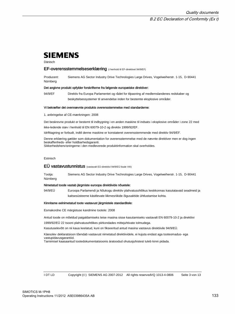
I DT LD Copyright ( ) SIEMENS AG 2007-2012 All rights reservedVQ 1013-4-0806 Seite 3 von 13
Dänisch
EF-overensstemmelseserklæring (i henhold til EF-direktivet 94/9/EF)
Producent: Siemens AG Sector Industry Drive Technologies Large Drives, Vogelweiherstr. 1-15, D-90441 Nürnberg
Det angivne produkt opfylder forskrifterne fra følgende europæiske direktiver: 94/9/EF Direktiv fra Europa Parlamentet og rådet for tilpasning af medlemslandenes redskaber og
beskyttelsessystemer til anvendelse inden for bestemte eksplosive områder.
Vi bekræfter det ovennævnte produkts overensstemmelse med standarderne:
1. anbringelse af CE-mærkningen: 2008
Det beskrevne produkt er bestemt til indbygning i en anden maskine til indsats i eksplosive områder i zone 22 med ikke-ledende støv i henhold til EN 60079-10-2 og direktiv 1999/92/EF. Idrifttagning er forbudt, indtil denne maskine er konstateret overensstemmende med direktiv 94/9/EF. Denne erklæring gælder som dokumentation for overensstemmelse med de nævnte direktiver men er dog ingen beskaffenheds- eller holdbarhedsgaranti. Sikkerhedshenvisningerne i den medleverede produktinformation skal overholdes. Estnisch
EÜ vastavustunnistus (vastavalt EÜ-direktiivi 94/9/EÜ lisale VIII)
Tootja: Siemens AG Sector Industry Drive Technologies Large Drives, Vogelweiherstr. 1-15, D-90441 Nürnberg
Nimetatud toode vastab järgmiste euroopa direktiivide nõuetele: 94/9/EÜ Euroopa Parlamendi ja Nõukogu direktiiv plahvatusohtlikus keskkonnas kasutatavaid seadmeid ja
kaitsesüsteeme käsitlevate liikmesriikide õigusaktide ühtlustamise kohta.
Kinnitame eelnimetatud toote vastavust järgmistele standarditele:
Esmakordne CE märgistuse kandmine tootele: 2008
Antud toode on mõeldud paigaldamiseks teise masina sisse kasutamiseks vastavalt EN 60079-10-2 ja direktiivi 1999/92/EÜ 22 tsooni plahvatusohtlikes piirkondades mittejuhtivate tolmudega. Kasutuselevõtt on nii kaua keelatud, kuni on fikseeritud antud masina vastavus direktiivile 94/9/EÜ.
Käesolev deklaratsioon tõendab vastavust nimetatud direktiividele, ei kujuta endast aga tooteomadus- ega vastupidavusgarantiid. Tarnimisel kaasaantud tootedokumentatsioonis äratoodud ohutusjuhistest tuleb kinni pidada.
Quality documentsB.2 EC Declaration of Conformity (Ex t)
SIMOTICS M-1PH8Operating Instructions 11/2012 A5E03986435A AB 133

I DT LD Copyright ( ) SIEMENS AG 2007-2012 All rights reservedVQ 1013-4-0806 Seite 4 von 13
Griechisch
VIII 94/9/E )
: Siemens AG Sector Industry Drive Technologies Large Drives, Vogelweiherstr. 1-15, D-90441 Nürnberg
:
94/9/
.
:
CE: 2008
22 EN 60079-10-2 1999/92/ .
94/9/E .
, .
. Spanisch
Declaración de conformidad CE (según el Anexo VIII de la Directiva 94/9/CE)
Fabricante: Siemens AG Sector Industry Drive Technologies Large Drives, Vogelweiherstr. 1-15, D-90441 Nürnberg
El producto arriba mencionado cumple con lo especificado en la Directiva Europea siguiente: 94/9/CE Directiva del Parlamento Europeo y del Consejo para la armonización de las leyes de los estados
miembros relativa a aparatos y sistemas de protección para uso conforme en atmósferas potencialmente explosivas.
Confirmamos que el producto arriba mencionado cumple las siguientes normas:
Primera colocación de la marca "CE": 2008
El producto mencionado está previsto para su montaje en otra máquina prevista para su instalación en atmósferas potencialmente explosivas de la zona 22 con polvo no conductor conforme a EN 60079-10-2 y la directiva 1999/92/CE. La puesta en marcha está prohibida hasta que no se haya confirmado que dicha máquina cumple la directiva 94/9/CE.
Esta declaración certifica el cumplimiento de las directivas mencionadas pero no garantiza las características ni la durabilidad. Deben observarse las consignas de seguridad de la documentación de producto suministrada.
Quality documentsB.2 EC Declaration of Conformity (Ex t)
SIMOTICS M-1PH8134 Operating Instructions 11/2012 A5E03986435A AB

I DT LD Copyright ( ) SIEMENS AG 2007-2012 All rights reservedVQ 1013-4-0806 Seite 5 von 13
Französisch
Déclaration CE de conformité (selon annexe VIII de la directive 94/9/CE)
Constructeur : Siemens AG Sector Industry Drive Technologies Large Drives, Vogelweiherstr. 1-15, D-90441 Nürnberg
Le produit désigné est conforme aux prescriptions de la directive européenne suivante :
94/9/EG Directive du parlement européen et du conseil concernant le rapprochement des législations des États membres pour les appareils et les systèmes de protection destinés à être utilisés en atmosphères explosibles.
Nous certifions la conformité du produit mentionné ci-dessus avec les normes :
Première apposition du marquage CE : 2008
Le produit désigné est destiné à l'implantation dans une autre machine pour l'utilisation en atmosphère explosible, zone 22 avec poussière non-conductrice selon la norme EN 60079-10-2 et la directive 1999/92/EG. La mise en service est proscrite tant que la conformité de cette machine avec la directive 94/9/EG n'est pas constatée.
Ce certificat atteste la conformité aux directives mentionnées, mais ne tient pas lieu de garantie de qualité ni de longévité. Respecter les consignes de sécurité figurant dans la documentation produit fournie. Italienisch
Dichiarazione di conformità CE (in conformità all’Annesso VIII della Direttiva Europea 94/9/CE)
Costruttore: Siemens AG Sector Industry Drive Technologies Large Drives, Vogelweiherstr. 1-15, D-90441 Nürnberg
Il prodotto designato è conforme alle prescrizioni della seguente Direttiva Europea: 94/9/CE Direttiva del Parlamento Europeo e del Consiglio concernente il ravvicinamento delle legislazioni
degli Stati membri relativa agli apparecchi e sistemi di protezione destinati ad essere utilizzati in atmosfera potenzialmente esplosiva.
Si certifica la conformità del prodotto sopra menzionato alle norme seguenti:
Prima apposizione del marchio CE: 2008
Il prodotto designato è destinato ad essere installato in un’altra macchina per l’impiego in aree a rischio di esplosione della Zona 22 con polveri non conduttrici secondo la norma EN 60079-10-2 e la Direttiva 1999/92/CE. La messa in servizio è vietata fintantoché non è stata accertata la conformità di questa macchina con la Direttiva 94/9/CE.
Questa dichiarazione certifica la conformità con le direttive citate, non costituisce però alcuna garanzia di caratteristiche di prodotto oppure di durata. Le avvertenze di sicurezza riportate nella documentazione di prodotto allegata devono essere rispettate.
Quality documentsB.2 EC Declaration of Conformity (Ex t)
SIMOTICS M-1PH8Operating Instructions 11/2012 A5E03986435A AB 135

I DT LD Copyright ( ) SIEMENS AG 2007-2012 All rights reservedVQ 1013-4-0806 Seite 6 von 13
Lettisch
EK atbilst bas deklar cija (Saska ar pielikumu VIII no EK direkt vas 94/9/EG) Ražot js: Siemens AG Sector Industry Drive Technologies Large Drives, Vogelweiherstr. 1-15, D-90441 Nürnberg
Ražojums atbilst turpm k min to Eiropas direkt vu specifik cij m: 94/9/EK Eiropas parlamenta un padomes direkt va, saska ar dal bvalstu likumiem, attiec uz ieceri
izmantot ier ces un aizsardz bas sist mas iesp jami spr dzienb stam vid .
Ar šo dokumentu apliecin m, ka iepriekš aprakst tais izstr jums atbilst š m pras m:
CE z mes pirm uzlikšana: 2008
Saska ar EN 60079-10-2 un direkt vu 1999/92/ EK šis izstr d jums paredz ts ieb v šanai citos meh nismos, kas izmantojami 22. zonas str vu nevadošu putek u spr dzienb stam vid . Nodošana ekspluat cij aizliegta kam r neb s apstiprin ta š s maš nas atbilst ba direkt vai 94/9/EK.
deklar cija apliecina atbilst bu nor taj m direkt m, bet t negarant atbilst bu nor taj m izstr juma paš m vai kalpošanas ilgumam.
iev ro droš bas nor jumi, kas ietverti pieg des komplekt iek autaj izstr juma dokument cij . Litauisch
EB atitikties deklaracija (pagal EB direktyvos 94/9/EB VIII pried )
Gamintojas: Siemens AG Sector Industry Drive Technologies Large Drives, Vogelweiherstr. 1-15, D-90441 Nürnberg
Nurodytas produktas atitinka šios Europos direktyvos reikalavimus:
94/9/EB Europos Parlamento ir Tarybos direktyva d l valstybi nari statym , susijusi su potencialiai sprogioje aplinkoje naudojama ranga ir apsaugos sistemomis, suderinimo
Tvirtiname, kad aukš iau min tas produktas atitinka normas:
Pirmasis CE ženklas pritvirtintas: 2008
Nurodytas produktas skirtas montuoti kit mašin , naudojam potencialiai sprogioje 22 zonos aplinkoje su nelaidžiomis dulk mis pagal EN 60079-10-2 ir direktyv 1999/92/EB. Draudžiama atiduoti ekspoatacijai tol, kol nenustatyta, kad ši mašina atitinka direktyv 94/9/EB.
Ši deklaracija patvirtina atitikim nurodytoms direktyvoms, ta iau negarantuoja joki ypatybi ar tinkamumo naudoti termino.
tina laikytis pridedamoje gaminio dokumentacijoje pateikt sp jam nurodym .
Quality documentsB.2 EC Declaration of Conformity (Ex t)
SIMOTICS M-1PH8136 Operating Instructions 11/2012 A5E03986435A AB

I DT LD Copyright ( ) SIEMENS AG 2007-2012 All rights reservedVQ 1013-4-0806 Seite 7 von 13
Ungarisch
EU egyez ségi nyilatkozat (a 94/9/EG számú EU-irányelv VIII függeléke szerint)
Gyártó: Siemens AG Sector Industry Drive Technologies Large Drives, Vogelweiherstr. 1-15, D-90441 Nürnberg
A jelzett termék megfelel a következ európai irányelvek el írásainak: 94/9/EG Az Európai Parlament és az Európa Tanács irányelve a tagállamok készülékekre és védelmi
rendszerekre vonatkozó jogi el írásainak harmonizálásáról a robbanásveszélyes területeken való rendeltetésszer használathoz.
A fent említett termék szabványokkal való egyez ségét a következ kkel igazoljuk:
A CE-jelzés els elhelyezése: 2008
A jelzett termék más gépbe történ elhelyezésre készült a 22-es zónába sorolt nemvezet porok környezetében területein történ alkalmazáshoz az EN 60079-10-2 szabvány és az 1999/92/EG irányelv szerint. Az üzembe helyezés mindaddig tilos, amíg a gép egyez ségét a 94/9/EG irányelvvel nem rögzítették. Ez a nyilatkozat tanúsítja a nevezett irányelveknek való megfelel séget, de semmilyen min ségi- vagy tartóssági garanciát nem jelent. A csatolt termékdokumentációban szerepl biztonsági utasításokat figyelembe kell venni. Maltesisch
UE-Dikjarazzjoni ta' Konformità (skond l-appendi i VIII tad-Direttiva tal-Kunsill ta’l-Unjoni Ewropea 94/9/KE)
Manifattur: Siemens AG Sector Industry Drive Technologies Large Drives, Vogelweiherstr. 1-15, D-90441 Nürnberg
Il-prodott imsemmi jikkorrispondi ma' l-instruzzjonijiet tad-direttivi ewropej. 94/9/KE Direttiva tal-parlament Ewropew u tal-Kunsill dwar l-approssimazzjoni tal-li ijiet ta’l-Istati Membri li
jirrigwardaw tag mir u sistemi ta' sigurtà g al u u skond ir-regolamenti f' oni fejn hemm periklu ta' splu jonijiet.
Nikkonfermaw il-konformità tal-prodott imsemmi ma' l-istandards:
Applikazzjoni tal-marka CE: 2008
Il-prodott imsemmi huwa ma sub biex ji i immuntat f'magna o ra g all-u u f' ona ta’ periklu 22 (trab mhux konduttiv) skond EN 60079-10-2 u d-Direttiva 1999/92/KE. Il-prodott ma jistax jibda' ji i m addem sakemm tigi determinata il-konformità ta' din il-magna mad-direttiva 94/9/KE.
Din id-dikjarazzjoni mhix garanzija ta’ responsabbiltà dwar il-prodott. Ir-regoli tad-dokumentazzjoni tal-prodott g andhom jigu obduti.
Quality documentsB.2 EC Declaration of Conformity (Ex t)
SIMOTICS M-1PH8Operating Instructions 11/2012 A5E03986435A AB 137

I DT LD Copyright ( ) SIEMENS AG 2007-2012 All rights reservedVQ 1013-4-0806 Seite 8 von 13
Niederländisch
EG-conformiteitsverklaring (volgens bijlage VIII van de EG-richtlijn 94/9/EG)
Fabrikant: Siemens AG Sector Industry Drive Technologies Large Drives, Vogelweiherstr. 1-15, D-90441 Nürnberg
Het omschreven product stemt overeen met de voorschriften van de volgende Europese richtlijn:
94/9/EG Richtlijn van het Europees Parlement en de Raad inzake de onderlinge aanpassing van de wetgevingen van de lidstaten betreffende apparaten en beveiligingssystemen bedoeld voor gebruik op plaatsen waar ontploffingsgevaar kan heersen.
Wij bevestigen de conformiteit van bovengenoemd product met de normen:
Eerste aanbrengen van het CE-keurmerk: 2008
Het omschreven product is bedoeld voor inbouw in een andere machine voor gebruik op explosiegevaarlijke plaatsen van zone 22 met niet-geleidende stoffen volgens EN 60079-10-2 en richtlijn 1999/92/EG. De inbedrijfneming is verboden tot de conformiteit van de machine met de Richtlijn 94/9/EG is vastgesteld.
Deze verklaring bevestigt de conformiteit met de genoemde richtlijnen, maar geeft geen garantie betreffende de gesteldheid of de houdbaarheid. De veiligheidsaanwijzingen in de meegeleverde productdocumentatie dienen te worden nageleefd. Norwegisch
EU konformitetserklæring (i henhold til EUs direktiv 94/9/EU) Produsent: Siemens AG Sector Industry Drive Technologies Large Drives, Vogelweiherstr. 1-15, D-90441 Nürnberg
Det angitte produktet er i overensstemmelse med forskriftene i følgende europeiske direktiv: 94/9/EU Direktiv fra EU-parlamentet og rådet for tilpasning av medlemsstatenes rettslige forskrifter for
utstyr og beskyttelsessystemer for forskriftemessig bruk i eksplosjonsfarlige områder.
Vi bekrefter det overnevnte produkts konformitet med standardene:
Første gangs plassering av Ce-MERKING: 2008
Det omtalte produktet er ment for innbygging i en annen maskin for bruk i eksplosjonsfarlige områder i sone 22 med ikke-ledende støv i henhold til EN 60079-10-2 og Direktiv 1999/92/EU. Det er forbudt å ta i bruk inntil konformiteten i denne maskinen er fastsatt ut fra Direktiv 94/9/EU. Denne erklæringen er ingen garanti om egenskaper. Henvisningene i den medfølgende produktdokumentasjonen må overholdes.
Quality documentsB.2 EC Declaration of Conformity (Ex t)
SIMOTICS M-1PH8138 Operating Instructions 11/2012 A5E03986435A AB
I DT LD Copyright ( ) SIEMENS AG 2007-2012 All rights reservedVQ 1013-4-0806 Seite 9 von 13
Polnisch
Deklaracja zgodno ci UE (wed ug za cznika VIII dyrektywy EG 94/9/EG) Producent: Siemens AG Sector Industry Drive Technologies Large Drives, Vogelweiherstr. 1-15, D-90441 Nürnberg
Wymieniony produkt jest zgodny z przepisami nast puj cej Dyrektywy Europejskiej:
94/9/EG Dyrektywa Parlamentu Europejskiego i Rady ds. Harmonizacji Przepisów Prawnych Pa stw Cz onkowskich dla Urz dze i Systemów Ochronnych w celu ich u ytkowania zgodnego z przeznaczeniem w obszarach zagro onych wybuchami.
Niniejszym potwierdzamy, e opisany powy ej produkt spe nia nast puj ce standardy:
Pierwsze u ycie znaku CE: 2008
Wymieniony produkt przeznaczony jest do wbudowania w inne maszyny do zastosowania w strefach zagro onych wybuchem 22 z nieprowadz cymi py ami wed ug normy EN 60079-10-2 i dyrektywy 1999/92/WE. Nie zaleca si uruchomienia bez stwierdzenia zgodno ci niniejszej maszyny z dyrektyw 94/9/EG.
Niniejsza deklaracja za wiadcza zgodno z wymienionymi dyrektywami, jednak nie stanowi gwarancji o w ciwo ciach lub trwa ci produktu. Nale y zapozna si ze wskazówkami bezpiecze stwa zawartych w do czonej dokumentacji produktu. Portugiesisch
Declaração de conformidade CE (segundo o anexo VIII da Directiva CE 94/9)
Fabricante: Siemens AG Sector Industry Drive Technologies Large Drives, Vogelweiherstr. 1-15, D-90441 Nürnberg
O produto especificado está em conformidade com o disposto nas seguintes Directivas Europeias:
94/9/CE Directiva do Parlamento Europeu e do Conselho relativa à aproximação das legislações dos Estados-Membros sobre aparelhos e sistemas de protecção destinados a serem utilizados em conformidade com as especificações em atmosferas potencialmente explosivas
Certificamos a conformidade do produto supracitado com as seguintes normas:
Primeira aposição da classificação CE: 2008
O produto supracitado destina-se à instalação noutra máquina para a utilização em atmosferas potencialmente explosivas da zona 22 com poeiras não condutoras em conformidade com a Norma EN 60079-10-2 e a Directiva 1999/92/CE. Não é autorizada a sua colocação em funcionamento enquanto não for verificada a conformidade da máquina com a Directiva 94/9/CE
A presente declaração atesta a conformidade com as directivas mencionadas, no entanto, não constitui uma garantia de qualidade ou durabilidade. Respeitar as indicações de segurança da documentação do produto juntamente fornecida.
Quality documentsB.2 EC Declaration of Conformity (Ex t)
SIMOTICS M-1PH8Operating Instructions 11/2012 A5E03986435A AB 139

I DT LD Copyright ( ) SIEMENS AG 2007-2012 All rights reservedVQ 1013-4-0806 Seite 10 von 13
Russisch
VIII 94/9/EG) : Siemens AG Sector Industry Drive Technologies Large Drives, Vogelweiherstr. 1-15, D-90441
Nürnberg
:
94/9/EG -, .
:
CE: 2008
22 EN 60079-10-2
1999/92/EG. , 94/9/EG.
. , .
Slowakisch
Prehlásenie o zhode s normami EÚ (v súlade s prílohou VIII Smernice EÚ . 94/9 /EEC, vrátane všetkých neskorších doplnkov) Výrobca: Siemens AG Sector Industry Drive Technologies Large Drives, Vogelweiherstr. 1-15, D-90441 Nürnberg Uvedený výrobok zodpovedá predpisom nasledovných európskych smerníc: 94/9/EEC Smernica Európskeho parlamentu a Rady o zosúladení zákonných požiadaviek lenských štátov
týkajúcich sa prístrojov a ochranných systémov, ktoré sú ur ené na použitie v rámci stanovených predpisov v prostrediach s nebezpe ím výbuchu.
Potvrdzujeme zhodu horeuvedeného výrobku s normami:
Ozna enie CE bolo prvýkrát uvedené: 2008
Uvedený výrobok je ur ený pre zabudovanie do iného stroja pre nasadenie v priestoroch s nebezpe ím výbuchu v zóne 22 s nevodivými prachovými asticami pod a normy EN 60079-10-2 a smernice EÚ . 1999/92/EEC
Uvedenie do prevádky nie je dovolené dovtedy, pokia nebude stanovená zhoda tohoto stroja so smernicou EÚ . 94/9/EEC.
Toto prehlásenie osved uje zhodu s uvedenými smernicami, neznamená však záruku vlastností alebo trvanlivosti. Dodržiavajte bezpe nostné pokyny pod a dodanej dokumentácie k výrobku.
Quality documentsB.2 EC Declaration of Conformity (Ex t)
SIMOTICS M-1PH8140 Operating Instructions 11/2012 A5E03986435A AB

I DT LD Copyright ( ) SIEMENS AG 2007-2012 All rights reservedVQ 1013-4-0806 Seite 11 von 13
Slowenisch
EG- izjava o skladnosti (po dodatku VIII EG smernici 94/9/EG) Proizvajalec: Siemens AG Sector Industry Drive Technologies Large Drives, Vogelweiherstr. 1-15, D-90441 Nürnberg
Ozna eni izdelek ustreza predpisom slede ih evropskih smernic: 94/9/EG Smernice Evropskega parlametna in sveta za zakonsko prilagajanje predpisov držav lanic za
naprave in varovalne sisteme.V eksplozijsko ogroženih podro jih velja uporaba ustreznih dolo il.
Potrjujemo skladnost zgoraj navedenega izdelka po normah:
Prva navedba CE – oznake: 2008
Ozna eni izdelek je namenjen za vgradnjo v drug stroj za uporabo v eksplozijsko ogroženih podro ji in to v conah 22 z neprevodnimi vrstami prahu po EN 60079-10-2 ter smernici 1999/92/EG. Uporaba je prepovedana, dokler ni zagotovljena skladnost stroja s predpisi 94/9/EG.
Ta izjava potrjuje skladnost z navedenimi direktivami, vendar pa ni garancija za samo sestavo ali garancija za vsebnost. Treba je upoštevati varnostna opozorila priložene dokumentacije produkta. Finnisch
EU-vaatimustemukaisuusvakuutus (EU-direktiivin 94/9/EY liitteen VIII mukaan)
Valmistaja: Siemens AG Sector Industry Drive Technologies Large Drives, Vogelweiherstr. 1-15, D-90441 Nürnberg
Kuvattu tuote vastaa seuraavien eurooppalaisten direktiivien vaatimuksia:
94/9/EY Euroopan Parlamentin ja Neuvoston direktiivi räjähdysvaarallisissa tiloissa käytettäväksi tarkoitettuja laitteita ja suojajärjestelmiä koskevan jäsenvaltioiden lainsäädännön lähentämisestä..
Vakuutamme, että yllä mainittu tuote on seuraavien standardien mukainen:
CE-merkintä annettu ensimmäisen kerran: 2008
Kuvattu tuote on tarkoitettu asennettavaksi toiseen koneeseen, jota käytetään räjähdysvaarallisissa, sähköä johtamatonta pölyä sisältävissä tilaluokan 22 tiloissa standardin EN 60079-10-2 ja direktiivin 1999/92/EY mukaisesti. Käyttöönotto on kielletty, kunnes koneen on todettu vastaavan direktiivin 94/9/EY määräyksiä.
Tämä selostus todistaa, että tuote vastaa mainittuja direktiivejä, mutta se ei ole ominaisuus- tai kestävyystakuu. Tuotteen mukana toimitettavan dokumentaation turvallisuusohjeita on noudatettava.
Quality documentsB.2 EC Declaration of Conformity (Ex t)
SIMOTICS M-1PH8Operating Instructions 11/2012 A5E03986435A AB 141

I DT LD Copyright ( ) SIEMENS AG 2007-2012 All rights reservedVQ 1013-4-0806 Seite 12 von 13
Schwedisch
EG-konformitetsförklaring (enligt artikel VIII i EG direktiv 94/9/EG)
Tillverkare: Siemens AG Sector Industry Drive Technologies Large Drives, Vogelweiherstr. 1-15, D-90441 Nürnberg
Den märkta produkten stämmer överens med föreskrifterna i följande europeiska direktiv: 94/9/EG Direktiv från det europeiska parlamentet och rådet för anpassning av medlemsstaternas rättsliga
föreskrifter angående apparater och skyddssystem för användning inom bestämda områden med explosionsrisk.
Vi bekräftar ovan angivna produkts överensstämmelse med standarderna:
Första placering av CE-märkning: 2008
Den märkta produkten är avsedd att byggas in i en annan maskin för insats i områden med explosionsrisk i zonen 22 med ej ledande damm enligt EN 60079-10-2 och direktiv 1999/92/EG. Idrifttagande är förbjudet fram till dess att denna maskins överensstämmelse med direktiv 94/9/EG har fastställts. Denna förklaring garanterar överensstämmelse med nämnda standarder, men gäller inte som garanti av något slag. Beakta säkerhetsanvisningarna i den medföljande produktdokumentationen. Rumänisch Declara ie de conformitate CE (în conformitate cu anexa VIII directivei CE 94/9/CE) Produc tor: Siemens AG Sector Industry Drive Technologies Large Drives Adresa: su a po tal 4743 Vogelweiherstr. 1-15
D-90025 Nürnberg D-90441 Nürnberg
Produsul mai sus men ionat corespunde prevederilor urm toarelor Directive Europene:
94/9/CE Directiva Parlamentului European i a Consiliului cu privire la uniformizarea legisla iei statelor membre pentru aparate i sisteme de protec ie cu privire la utilizarea conform cu scopul de fabrica ie în zone cu pericol de explozie.
Confirm m conformitatea produsului mai sus men ionat cu urm toarele norme:
Modul ini ial de montare al simbolului CE: 2008 Produsul mai sus men ionat este conceput pentru montarea într-o alt ma in pentru utilizarea în zone cu pericol de explozie zonei 22 cu pulberi neconductibile cu EN 60079-10-2 i directiva 1999/92/CE. Punerea în func iune este interzis pân când se stabile te conformitatea acestei ma ini cu directiva 94/9/CE. Aceast declara ie confirm conformitatea cu directivele men ionate, îns nu reprezint o garan ie a calit ii sau fiabilit ii. Trebuie respectate indica iile de siguran din documenta ia livrat cu produsul.
Quality documentsB.2 EC Declaration of Conformity (Ex t)
SIMOTICS M-1PH8142 Operating Instructions 11/2012 A5E03986435A AB

I DT LD Copyright ( ) SIEMENS AG 2007-2012 All rights reservedVQ 1013-4-0806 Seite 13 von 13
Bulgarisch
- , ( VIII 94/9/EG) : Siemens AG Sector Industry Drive Technologies Large Drives
: Postfach 4743 Vogelweiherstr. 1-15 D-90025 Nürnberg D-90441 Nürnberg
:
94/9/EG
.
:
CE- : 2008
22 , EN 60079-10-2 1999/92/EG.
, 94/9/EG.
, .
, .
Quality documentsB.2 EC Declaration of Conformity (Ex t)
SIMOTICS M-1PH8Operating Instructions 11/2012 A5E03986435A AB 143

Quality documentsB.2 EC Declaration of Conformity (Ex t)
SIMOTICS M-1PH8144 Operating Instructions 11/2012 A5E03986435A AB

Additional documents C
If you have any questions or problems, contact your Siemens service center (Page 125).
SIMOTICS M-1PH8Operating Instructions 11/2012 A5E03986435A AB 145
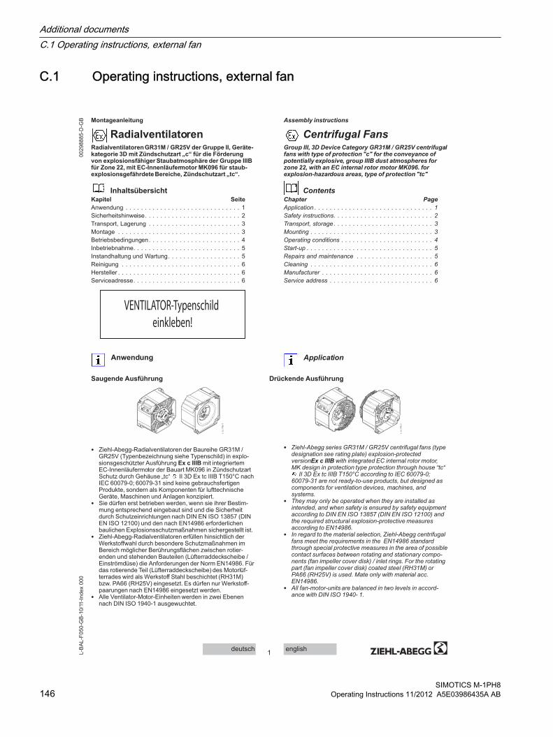
Montageanleitung
RadialventilatorenRadialventilatoren GR31M / GR25V der Gruppe II, Geräte-kategorie 3D mit Zündschutzart „c“ für die Förderung von explosionsfähiger Staubatmosphäre der Gruppe IIIB für Zone 22, mit EC-Innenläufermotor MK096 für staub-explosionsgefährdete Bereiche, Zündschutzart „tc“.
InhaltsübersichtKapitel Seite
Anwendung . . . . . . . . . . . . . . . . . . . . . . . . . . . . . . 1Sicherheitshinweise. . . . . . . . . . . . . . . . . . . . . . . . . 2Transport, Lagerung . . . . . . . . . . . . . . . . . . . . . . . . 3Montage . . . . . . . . . . . . . . . . . . . . . . . . . . . . . . . . 3Betriebsbedingungen. . . . . . . . . . . . . . . . . . . . . . . . 4Inbetriebnahme. . . . . . . . . . . . . . . . . . . . . . . . . . . . 5Instandhaltung und Wartung. . . . . . . . . . . . . . . . . . . 5Reinigung . . . . . . . . . . . . . . . . . . . . . . . . . . . . . . . 6Hersteller . . . . . . . . . . . . . . . . . . . . . . . . . . . . . . . . 6Serviceadresse. . . . . . . . . . . . . . . . . . . . . . . . . . . . 6
VENTILATOR-Typenschild
einkleben!
Anwendung
Saugende Ausführung Drückende Ausführung
• Ziehl-Abegg-Radialventilatoren der Baureihe GR31M / GR25V (Typenbezeichnung siehe Typenschild) in explo-sionsgeschützter Ausführung Ex c IIIB mit integriertem EC-Innenläufermotor der Bauart MK096 in Zündschutzart Schutz durch Gehäuse „tc“ II 3D Ex tc IIIB T150°C nach IEC 60079-0; 60079-31 sind keine gebrauchsfertigen Produkte, sondern als Komponenten für lufttechnische Geräte, Maschinen und Anlagen konzipiert.
• Sie dürfen erst betrieben werden, wenn sie ihrer Bestim-mung entsprechend eingebaut sind und die Sicherheit durch Schutzeinrichtungen nach DIN EN ISO 13857 (DIN EN ISO 12100) und den nach EN14986 erforderlichen baulichen Explosionsschutzmaßnahmen sichergestellt ist.
• Ziehl-Abegg-Radialventilatoren erfüllen hinsichtlich der Werkstoffwahl durch besondere Schutzmaßnahmen im Bereich möglicher Berührungsflächen zwischen rotier-enden und stehenden Bauteilen (Lüfterraddeckscheibe / Einströmdüse) die Anforderungen der Norm EN14986. Für das rotierende Teil (Lüfterraddeckscheibe) des Motorlüf-terrades wird als Werkstoff Stahl beschichtet (RH31M) bzw. PA66 (RH25V) eingesetzt. Es dürfen nur Werkstoff-paarungen nach EN14986 eingesetzt werden.
• Alle Ventilator-Motor-Einheiten werden in zwei Ebenen nach DIN ISO 1940-1 ausgewuchtet.
Assembly instructions
Centrifugal FansGroup III, 3D Device Category GR31M / GR25V centrifugal fans with type of protection "c" for the conveyance of potentially explosive, group IIIB dust atmospheres for zone 22, with an EC internal rotor motor MK096. for explosion-hazardous areas, type of protection "tc"
ContentsChapter Page
Application . . . . . . . . . . . . . . . . . . . . . . . . . . . . . . . 1
Safety instructions. . . . . . . . . . . . . . . . . . . . . . . . . . 2
Transport, storage. . . . . . . . . . . . . . . . . . . . . . . . . . 3
Mounting . . . . . . . . . . . . . . . . . . . . . . . . . . . . . . . . 3
Operating conditions . . . . . . . . . . . . . . . . . . . . . . . . 4
Start-up . . . . . . . . . . . . . . . . . . . . . . . . . . . . . . . . . 5
Repairs and maintenance . . . . . . . . . . . . . . . . . . . . 5
Cleaning . . . . . . . . . . . . . . . . . . . . . . . . . . . . . . . . 6
Manufacturer . . . . . . . . . . . . . . . . . . . . . . . . . . . . . 6
Service address . . . . . . . . . . . . . . . . . . . . . . . . . . . 6
Application
• Ziehl-Abegg series GR31M / GR25V centrifugal fans (type designation see rating plate) explosion-protected versionEx c IIIB with integrated EC internal rotor motor, MK design in protection type protection through house “tc“
II 3D Ex tc IIIB T150°C according to IEC 60079-0; 60079-31 are not ready-to-use products, but designed as components for ventilation devices, machines, and systems.
• They may only be operated when they are installed as intended, and when safety is ensured by safety equipment according to DIN EN ISO 13857 (DIN EN ISO 12100) and the required structural explosion-protective measures according to EN14986.
• In regard to the material selection, Ziehl-Abegg centrifugal fans meet the requirements in the EN14986 standard through special protective measures in the area of possible contact surfaces between rotating and stationary compo-nents (fan impeller cover disk) / inlet rings. For the rotating part (fan impeller cover disk) coated steel (RH31M) or PA66 (RH25V) is used. Mate only with material acc. EN14986.
• All fan-motor-units are balanced in two levels in accord-ance with DIN ISO 1940- 1.
1englishdeutsch
00298885-D
-GB
L-B
AL-F
050-G
B-1
0/1
1-I
ndex
000
C.1 Operating instructions, external fan
Additional documentsC.1 Operating instructions, external fan
SIMOTICS M-1PH8146 Operating Instructions 11/2012 A5E03986435A AB

Sicherheitshinweise
• Die Normen EN 60079-0 Elektrische Betriebsmittel für explosionsgefährdete Bereiche (Allgemeine Bestim-mungen), EN 60079-31 (Schutz durch Gehäuse „tc“) und alle für Ventilatoren in explosionsgeschützter Ausführung relevanten Normen müssen eingehalten werden. Damit wird der Betrieb von Motoren in potentiell explosionsfä-higen Staub-Luft-Gemischen in explosionsgefährdeten Bereichen der Kategorie 3D (Zone 22) zulässig.
• Die Ventilatoren sind nur zur Förderung von Luft oder explosionsfähiger Staub-Luft-Gemische der Zone 22 bestimmt.
• Fördermedien, die die Werkstoffe des Radialventilators angreifen, sind nicht zulässig. Verwendete Materialien:– RH25V: PA66+6 (GF + CF)40; Stahl DIN EN 10346-
DX54D– RH31M: Lackbasis Polyacrylat, Polyisozyanat;
Beschichtungspulverbasis Polyester-Epoxid-Harz; Stahl DIN EN 10042-DX53D+Z275-N-A
– Einströmdüse (RH25V): Blech DIN EN 10088-2 (1.4571)
– Einströmdüse (RH31M): Blech DIN EN 1652-Cu-DHP-R220
• Die Angabe der maximalen Oberflächentemperatur auf dem Motor-Leistungsschild muss die unterste Zündtempe-ratur des möglicherweise auftretenden, brennbaren Staubes unterschreiten.
• Betreiben Sie den Ventilator nur nach seiner bestim-mungsgemäßen Verwendung und nur bis zur max. zuläs-sigen Betriebsdrehzahl gemäß Angaben auf dem Venti-lator-/ Motorlüfterrad-Typenschild. Ein Überschreiten der max. Betriebsdrehzahl ist nicht zulässig. Das Laufrad kann bersten – Lebensgefahr!→ siehe Betriebsbedin-gungen.
• Die max. zulässigen Betriebsdaten auf dem Ventilator-Leistungsschild gelten für eine Luftdichte ρ = 1,2 kg/m 3.
• Montage und elektrische Installation darf nur durch geeig-netes Fachpersonal, das die einschlägigen Vorschriftenbeachtet, vorgenommen werden! – Zur Vermeidung von Störfällen und zum Schutz des
Motors muss der Motor durch die eingebauten Kaltleiter bei einer Betriebsstörung (z.B. unzulässig hohe Mediumstemperatur) in Verbindung mit einem Auslöse-gerät (Kennzeichnung II (2) G siehe Richtlinie 94/9/EG) und einem externen Schütz vom Netz getrennt werden.
– max. Prüfspannung der Kaltleiter: 2,5V– Ein stromabhängiger Schutz ist nicht zulässig und auch
als Sekundärschutz nicht möglich.– Die Motoren enthalten Drillingskaltleiter. Mehr als zwei
Kaltleiterketten dürfen nicht in Serie geschaltet werden, da dies zu undefiniertem Abschalten führen kann.
• Alle Ventilator-Motor-Einheiten werden mit herausge-führtem Kabel geliefert. Die zulässige Mediumstemperatur beträgt -20°C...+40°C. Abweichende Mediumstempera-turen sind dem Typenschild oder dem Datenblatt zu entnehmen. Die Einhaltung der EN ISO 13857 bzw. EN 60529 IP20 bezieht sich nur auf den montierten Berühr-schutz sofern dieser zum Lieferumfang gehört. Für die vollständige Erfüllung der EN ISO 13857 bzw. EN 60529 ist der Anlagenbauer verantwortlich.
• Sicherheitsbauteile, z.B. Schutzgitter, dürfen weder demontiert noch umgangen oder außer Funktion gesetzt werden!
• Wenn durch die Geräte- oder Anlagenkonstruktion das Ansaugen oder Hereinfallen von Fremdkörpern nicht verhindert werden kann, es besteht die Gefahr der Explo-sion einer zündfähigen Staub-Luftatmosphäre, sind vom Betreiber zusätzliche Maßnahmen zu treffen, um dies zu verhindern, z.B. durch das Anbringen eines zusätzli-chen Schutzgitters mit einer engen Maschenweite. Bei den Einbaubeispielen die im nebenstehenden Bild mit einem Blitz gekennzeichnet sind, muss mit einer erhöhten Gefahr bezüglich dem Hereinfallen von Fremdkörpern gerechnet werden.
Safety instructions
• The standards Explosive atmospheres - Part 0: Equipment (General Requirements), EN 60079-15 (Explosive atmos-pheres - Part 31: Equipment dust ignition protection by enclosure "t") and all standards relevant to fans in explo-sion protected versions must be complied with. That makes operation of motors in potentially explosive dust-air mixtures in Category 3D (Zone 22) explosive atmosphere areas permissible.
• The fans are intended to convey air or potentially explosive Zone 22 dust-air mixtures.
• Pumping media that corrode the centrifugal fans are not permitted. Materials used:– RH25V: PA66+6 (GF + CF)40; Steel DIN EN 10346-
DX54D– RH31M: Varnish base polyacrylate, polyisocyanate;
coated powder basis polyester epoxy resin; Steel DIN EN 10042-DX53D+Z275-N-A
– Air inlets (RH25V): Plate DIN EN 10088-2 (1.4571)– Inlet ring (RH31M): Sheet DIN EN 1652-Cu-DHP-R220
• The specification of the maximum surface temperature on the motor rating plate must be less than the lowest ignition temperature of any possibly occurring, flammable dust.
• Operate the fan only in accordance with its intended use and only up to the max. permissible operating speed in compliance with the specifications on the fan/motor impel-ler/rating plate. Exceeding the max. operating speed is prohibited. The impeller can burst – danger of death!→ see operating instructions.
• The maximum permissible operating data given on the fan-rating-plate are valid from air density ρ=1,2 kg/m3.
• Mounting and electrical installation may only be carried out by trained specialized personnel who observe the relevant regulations!– In order to prevent malfunctions and in order to protect
the motor the motor must be disconnected from the mains by the integrated PTC in connection with a trig-gering device (identification II (2)G; see directive 94/9/EU) and an external contactor during an opera-tions failure (e.g., inadmissibly high medium tempera-ture).
– max. test voltage of the PTC: 2.5V– A current dependent protection is not admissible and
also not possible as secondary protection.– The motors have triplet PTC’s. More than two PTC’s
may not be connected in series, as this can lead to undefined shut-downs.
• All fan-motor-units are supplied with the cable led out. The permissible media temperature is -20°C...+40°C. Refer to the rating plate or data sheet for non-complying media temperatures. Compliance with EN ISO 13857 or EN 60529 IP20 relates solely to the mounted contact protec-tion insofar as it is included in the scope of delivery. The system constructor is responsible for compliance with EN ISO 13857 or EN 60529.
• Safety features, e.g. guard grilles, are not to be disman-tled, circumvented or made inoperative!
• If sucking or falling in of foreign objects cannot be prevented due to the device design or plant construction, there is a hazard of explosion of an ignitable dust-air mixture; the operator must take additional measures to prevent this from occurring, for instance by attaching an additional narrow meshed guard grill. In the installation examples marked with a lightning symbol in the picture opposite, one must reckon with an increased hazard regarding foreign objects being able to fall in.
2englishdeutsch
00298885-D
-GB
L-B
AL-F
050-G
B-1
0/1
1-I
ndex
000
Additional documentsC.1 Operating instructions, external fan
SIMOTICS M-1PH8Operating Instructions 11/2012 A5E03986435A AB 147

• Ein Restrisiko durch Fehlverhalten, Fehlfunktion, oder Einwirken höherer Gewalt beim Betreiben des Radialventi-lators kann nicht völlig ausgeschlossen werden. Der Planer, Betreiber oder Erbauer des Gerätes, der Maschine oder Anlage muss durch geeignete Sicherheitsmaß-nahmen nach DIN EN ISO 12100 und insbesondere nach EN14986 verhindern, dass eine Gefährdungssituation entstehen kann.
• Die Einhaltung der EMV-Richtlinie 2004/108/EG wird nur dann gewährleistet, wenn das Produkt direkt an das übliche Stromversorgungsnetz angeschlossen ist. Wird dieses Produkt in eine Anlage integriert oder mit anderen Komponenten (z.B. Regel- und Steuergeräte) komplettiert und betrieben, so ist der Hersteller oder Betreiber der Gesamtanlage für die Einhaltung der EMV-Richtlinie 2004/108/EG verantwortlich.
• Beachten Sie die Hinweise zur Instandhaltung und Wartung.
• Diese Montageanleitung ist Teil des Produktes und als solche zugänglich aufzubewahren.
Transport, Lagerung
• Ziehl-Abegg- Ventilatoren sind ab Werk für die jeweils vereinbarte Transportart entsprechend verpackt.
• Transportieren Sie den/die Ventilator/-en entweder origi-nalverpackt oder größere Ventilatoren an den dafür vorge-sehenen Transportvorrichtungen (Gehäuseflansch, Befes-tigungswinkel, Bohrungen am Motorgehäuse zum Einschrauben von Ringschrauben) mit geeigneten Trans-portmitteln.
• Beachten Sie die Gewichtsangaben auf dem Typenschild.• Nicht am Anschlusskabel transportieren!• Vermeiden Sie Schläge und Stöße, besonders bei Geräten
mit aufgebauten Ventilatoren.• Achten Sie auf evtl. Beschädigung der Verpackung oder
des Ventilators.• Lagern Sie den Ventilator trocken und wettergeschützt in
der Originalverpackung oder schützen Sie ihn bis zur endgültigen Montage vor Schmutz und Wettereinwirkung.
• Vermeiden Sie extreme Hitze- oder Kälteeinwirkung.• Vermeiden Sie zu lange Lagerzeiträume (wir empfehlen
max. ein Jahr) und überprüfen Sie vor dem Einbau die ordnungsgemäße Funktion der Motorlagerung.
Montage
• Es obliegt der Verantwortung des System- oder Anlagen-bauers, dass anlagenbezogene Einbau- und Sicherheits-hinweise sich im Einklang mit den geltenden Normen (DIN EN ISO 12100, 13857, DIN EN 60529, EN14986) befinden.
• Für alle Ventilatorbauformen gilt:– Nicht verspannt einbauen. Anbauflächen müssen eben
sein. Verformungen und Verlagerungen dürfen nicht zum Anschlagen oder Schleifen rotierender Teile führen.
• A residual risk through inappropriate behavior, malfunction, or affects through acts of God or force majeure during operation of the centrifugal fan cannot be completely excluded. The planner, operator, or constructor of the system, machine, or plant must prevent a hazardous situa-tion from arising by taking appropriate safety precautions in accordance with DIN EN ISO 12100 and especially in accordance with the EN14986.
• Compliance with EMC guideline 2004/108/EG is only guaranteed if the product is connected to the standard electricity supply grid. If this product is integrated into a system or complemented and operated with other components (e.g. controller units and control devices), the manufacturer or operator of the entire system is responsible for the compliance with the EMC directive 2004/108/EG.
• Pay attention to the notes which concerning maintenance and service.
• These assembly instructions are part of the product and, as such, are to be kept accessible at all times.
Transport, storage
• Ziehl-Abegg Fans are packaged at the factory to comply with requirements for the agreed mode of transport.
• Transport the fan(s) either in the original packaging or, in the case of larger fans, on the dedicated transportation fixtures (housing flange, mounting bracket, holes on the motor housing to attach lifting eye bolts), using a suitable means of transportation.
• Observe the weight data on the type code
• Do not transport the fan by the connecting cable!
• Avoid impacts and collisions, especially on fans set-up on devices.
• Be on the alert for any damage to the packaging or the fan.
• Store the fan in the original packaging in a dry area protected from the weather or protect it from dirt and weather until final installation.
• Avoid exposure to extreme heat and cold.
• Avoid excessive storage periods (we recommend a one year max.) and inspect the motor bearings for proper oper-ation prior to installation.
Mounting
• The system manufacturer or the machine builder is responsible that the inherent installation and security infor-mations are harmonised with the valid standard and guide-lines (DIN EN ISO 12100,13857, DIN EN 60529,EN14986).
• The following applies to all fan designs:– Do not install distorted. The installation area must be
level. Deformations and misalignments must not result in rotating parts striking or grinding.
3englishdeutsch
00298885-D
-GB
L-B
AL-F
050-G
B-1
0/1
1-I
ndex
000
Additional documentsC.1 Operating instructions, external fan
SIMOTICS M-1PH8148 Operating Instructions 11/2012 A5E03986435A AB

– Bei Einhaltung der Werkstoffpaarung müssen folgende Mindestspalte eingehalten werden: zwischen rotier-enden und stehenden Teilen darf der Mindestspalt nicht kleiner als 1 % des maßgeblichen Kontaktdurchmes-sers, aber nicht weniger als 2 mm in axialer oder radialer Richtung sein und muss nicht mehr als 20 mm betragen. Das Spaltmaß „S“ nach Abb. wurde bereits im Auslieferungszustand eingestellt. Vor Einbau ist der Ventilator vom Anlagenbauer auf gleichmäßiges Spaltmaß zu überprüfen. Bei Abweichung ist der Hersteller zu informieren.
– Zur Befestigung des Ventilators und der Schutzgitter, Schrauben der Festigkeitsklasse 8.8 verwenden und mit geeigneter Schraubensicherung versehen. Zul. Anzugsmomente: M5 = 5,5Nm; M8 =23 Nm.
– Bestimmte Betriebspunkte / Drehzahlen dürfen bei auftretenden Eigenresonanzen aufgrund von Anbau-teilen nicht gefahren werden. Die Überprüfung auf Eigenresonanz ist vom Anlagenbauer bei Inbetrieb-nahme durchzuführen.
– Der Ventilator darf nur an Stromkreise angeschlossen werden, die mit einem allpolig trennenden Schalter abschaltbar sind.
– Elektrischer Anschluss entsprechend dem im Klem-menkasten angebrachten Schaltbild! Das Anschluss-schaltbild muss am Betriebsort verfügbar sein.
– Motoranschlusskabel mit Kabelbindern oder Kabel-schellen befestigen. Die Befestigung ist so vorzu-nehmen, dass das Kabel nach dem Befestigen noch verschiebbar ist, und somit die Kabelisolation nicht beschädigt wird.
– Werden Gefährdungen durch Blitzschlag festgestellt, müssen die Anlagen durch geeignete Blitzschutzmaß-nahmen geschützt werden.
– Anlagen müssen in ausreichendem Sicherheitsabstand zu Sendeanlagen aufgestellt oder durch geeignete Abschirmung geschützt werden.
Betriebsbedingungen
• Das Ventilator-Leistungsschild enthält die Bemes-sungsspannung und Schaltung und bis zu welchen Daten der Ventilator belastet werden kann. Höhere Werte als die gestempelte Aufnahmeleistung / gestempelten Aufnahmeleistungen bedeuten, dass der Ventilator in einem nicht zulässigen Betrieb arbeitet.
• Motorschutz: siehe Sicherheitshinweise• Schalthäufigkeit: Der Motor ist für Dauerbetrieb S1
bemessen. Die Steuerung darf keine extremen Schaltbe-triebe zulassen!
• A-bewerteter Schallleistungspegel größer 80dB(A) möglich.
– For compliance with material mating, maintain the following minimum gaps: between rotating and stationary parts, the minimum gap must not be less than 1 % of the decisive contact diameter, but not less than 2 mm in axial or radial direction and must amount to no more than 20 mm. The gap dimension „S“ in the figure was already set in the as-delivered condition. Before installing the fan, the plant constructor is to check for uniform gap dimension. Inform the manufac-turer if there are any non-compliances.
– To attach the fan and the guard grill, use Strength Class 8.8 bolts and provide with suitable bolt locking. Perm. torque: M5 = 5,5Nm; M8 =23 Nm.
– Certain operating points / speeds may not be run during self-resonance of the attached components. The verifi-cation of self-resonance is to be carried out by the system constructor during start-up operation.
– Connect fan only to electrical circuits that can be disconnected with an all-pole isolating switch.
– Electrical connection corresponding to the wiring diagram in the terminal box! The connection diagrams must be available at the operating location.
– Fasten the motor connection with cable ties or cable clamps. Attachment is to be carried out in such a way that the cable can still be moved after attachment and so that the cable insulation will not be damaged.
– If hazards from lightning strikes have been ascertained, the system must be protected through the use of suit-able lightning protection measures.
– Systems must be sufficiently separated from transmit-ting installations or be protected through suitable shielding.
Operating conditions
• The fan rating plate includes the rated voltage and circuit and to which data the fan can be loaded. Values higher than the stamped power consumption / stamped power consumptions mean the fan is working in an impermissible range.
• Motor protection: see safety notifications
• Switching frequency: The motor is dimensioned for contin-uous operation S1. The control must not allow any extreme switching modes!
• A-weighted sound power levels of over 80dB(A) possible.
4englishdeutsch
00298885-D
-GB
L-B
AL-F
050-G
B-1
0/1
1-I
ndex
000
Additional documentsC.1 Operating instructions, external fan
SIMOTICS M-1PH8Operating Instructions 11/2012 A5E03986435A AB 149

Inbetriebnahme
• Vor Erstinbetriebnahme prüfen:– Einbau und elektrische Installation fachgerecht abge-
schlossen?– Sicherheitseinrichtungen montiert?– Montagerückstände und Fremdkörper aus Ventilator-
raum entfernt?– Lüfterrad darf nicht an feststehendem Gehäuseteil
schleifen (→ Zündfunke!).– Schutzleiter angeschlossen?– Kaltleiter und Auslösegerät fachgerecht angeschlossen
und funktionsfähig?– Kabeleinführung dicht?– Stimmen Einbaulage und Anordnung der Kondenswas-
serlöcher überein?– Stimmen Anschlussdaten mit den Daten auf dem Venti-
lator-Typenschild (Klebeschild) überein?• Inbetriebnahme darf erst erfolgen, wenn alle Sicherheits-
hinweise überprüft und eine Gefährdung ausgeschlossen ist.– Drehrichtung kontrollieren (Drehrichtungspfeil auf
Laufrad bzw. am Ventilatorgehäuse).– Auf ruhigen Lauf achten.– Starke Schwingungen durch unruhigen Lauf (Unwucht),
z. B. durch Transportschaden oder unsachgemäße Handhabung, können zum Ausfall führen, ggf. Unwucht überprüfen lassen. Das Laufrad kann bersten – Lebensgefahr!
– Alle leitfähigen Anbau- und Zubehörteile müssen geerdet werden, z. B. durch Kontaktscheiben. Dadurch kann das Entfernen der Lackschicht / Beschichtung entfallen.
– Bei der Aufstellung / Inbetriebnahme müssen Umge-bungstemperatur, Luftfeuchtigkeit, Umgebungsver-schmutzung und Korrosion durch die Umgebungsatmo-sphäre berücksichtigt werden.
Instandhaltung und Wartung
• Der EC-Innenläufermotor ist durch Verwendung von Kugellagern mit “Lebensdauerschmierung” (Sonderbefet-tung) wartungsfrei.
• Bei Anzeichen von Verschleiß, oder spätestens nach 40.000 h, ist ein Lagerwechsel erforderlich. Da für den Lagerwechsel Spezialwerkzeug notwendig ist und spezielle Lager mit Ziehl-Abegg Sonderbefettung verwendet werden, kann der Lagerwechsel nur durch Ziehl-Abegg durchgeführt werden.
• Achten Sie auf untypische Laufgeräusche!• Ablagerungen am Laufrad können zur Unwucht und damit
zu Schäden führen. Regelmäßige Inspektion und Reini-gung ist zwingend erforderlich, ggf. Unwucht überprüfen lassen. Das Laufrad kann bersten – Lebensgefahr!
• Außenaufstellung: Bei längeren Stillstandszeiten in feuchter Atmosphäre wird empfohlen die Ventilatoren wöchentlich für mindestens 2 Std. in Betrieb zu nehmen, damit eventuell eingedrungene Feuchtigkeit verdunstet.
• Bei allen Instandhaltungs- und Wartungsarbeiten:– Sicherheits- und Arbeitsvorschriften (DIN EN 50 110,
IEC 364) beachten.– Das Ventilatorlaufrad muss still stehen!– Stromkreis ist unterbrochen und gegen Wiederein-
schalten gesichert.– Spannungsfreiheit feststellen.– Keine Wartungsarbeiten am laufenden Ventilator!
• Eine Laufraddemontage und Wiedermontage ist nicht gestattet.
• Halten Sie die Luftwege des Ventilators frei - Gefahr durch herausfliegende Gegenstände!
• Der Anlagenbauer muss eine leichte Zugänglichkeit für Reinigungs- und Inspektionsarbeiten ermöglichen.
Start-up
• Before initial commissioning, check:– Installation and electrical connection have been prop-
erly completed?– Have the safety devices been installed?– All leftover installation materials and other foreign mate-
rials have been removed from the fan cavity.– The impeller must not rub against any stationary
housing parts (→ sparks!).– Is the protective earth connected?– Thermistor and triggering device have been properly
installed and are operational.– Cable gland is sealed.– Installation position and the arrangement of condensa-
tion water drains correspond to each other?– Connection data complies with the specifications on the
type plate?
• Commissioning may only take place if all safety instruc-tions have been checked and danger can be excluded.– Check the direction of rotation (direction of rotation
arrow on the impeller or on the fan housing).– Watch out for smooth operation.– Strong vibrations caused by uneven running (imbal-
ance), for instance due to shipping damage or improper handling, can lead to failure. The impeller can burst – Danger of death!
– All conductive attachment and accessory parts must be grounded e.g., with contact disks: By doing so, removal of the paint coat / coating can be omitted.
– During erection / start-up operation, the ambient temperature, air humidity, environmental contamination, and corrosion through the surrounding atmosphere must be taken into consideration.
Repairs and maintenance
• Through the use of ball bearings with "lifetime lubrication" (special greasing), the EC internal rotor motor is mainte-nance-free.
• Upon signs of wear or latest after 40,000 h, a bearing replacement is required. Since special tools are required to replace the bearing and since specific bearings with special Ziehl-Abegg lubrication are employed, only Ziehl-Abegg AG is allowed to replace the bearing.
• Take note of abnormal operating noise!
• Deposits on the impeller can lead to imbalance, causing damage. Periodic inspection and cleaning is mandatory; it applicable, have the imbalance checked. The impeller can burst – Danger of death!
• Outdoor fans: If a fan is stationary for long periods in a humid atmosphere, it should be switched ON for minimum of two hours every week to remove any moisture that may have condensed within the motor.
• For all repair and maintenance work:– Observe the safety and labour regulations (DIN EN 50
110, IEC 364).– The fan impeller must be at a standstill!– Open the electrical circuit and secure against being
switched back on. – Verify the absence of voltage.– No maintenance work at running fan!
• Disassembling and remounting the impeller is prohibited.
• Keep the airways of the fan free- danger because of objects dropping out!
• The system constructor must enable easy access for cleaning and inspection work.
• Before switching off the fan, make sure that no Ex atmos-phere is present.
5englishdeutsch
00298885-D
-GB
L-B
AL-F
050-G
B-1
0/1
1-I
ndex
000
Additional documentsC.1 Operating instructions, external fan
SIMOTICS M-1PH8150 Operating Instructions 11/2012 A5E03986435A AB

• Vor dem Abschalten des Ventilators ist sicher zu stellen, dass keine Ex-Atmosphäre anliegt.
• Bei allen anderen Schäden (z. B. Kabel- und Leitungs-einführungen, Wicklungen und Kabel) wenden Sie sich bitte an unsere Serviceabteilung.
Reinigung
• Regelmäßige Inspektion, ggf. mit Reinigung erforderlich um Unwucht durch Verschmutzung zu vermeiden.– Durchströmungsbereich des Ventilators säubern.
• Achten Sie auf schwingungsarmen Lauf.• Reinigungsintervalle je nach Verschmutzungsgrad des
Laufrades.• Der komplette Ventilator darf mit einem feuchten Putztuch
gereinigt werden.• Zur Reinigung dürfen keine aggressiven, lacklösenden
Reinigungsmittel verwendet werden.• Verwenden Sie keinesfalls einen Hochdruckreiniger
oder Strahlwasser zur Reinigung.
• Nassreinigung unter Spannung kann zum Strom-schlag führen - Lebensgefahr!
• Nach dem Reinigungsprozess muss der Motor zum Abtrocknen 30 Minuten bei 80-100% der max. Drehzahl betrieben werden, damit eventuell eingedrungenes Wasser verdunsten kann.
Hersteller
Unsere Produkte sind nach den einschlägigen internationalen Vorschriften gefertigt (Auflistung und Ausgabestände siehe EG-Einbauerklärung und EG-Konformitätserklärung).Haben Sie Fragen zur Verwendung unserer Produkte oder planen Sie spezielle Anwendungen, wenden Sie sich bitte an:
Ziehl-Abegg AGHeinz-Ziehl-StraßeD-74653 KünzelsauTel. 07940/16-0Fax 07940/[email protected]
Serviceadresse
Länderspezifische Serviceadressen siehe Homepage unter www.ziehl-abegg.com
• For all other defects (e.g. cable and wire lead-ins, windings and cables), please contact our service department.
Cleaning
• Regular inspection, and cleaning is necessary to prevent imbalance due to ingress of dirt.– Clean the fans`s flow area.
• Watch out for vibration free motion.
• The cleaning interval depends on the degree to which the impeller is soiled.
• You can clean the entire fan with a moist cloth.
• Do not use any aggressive, paint solvent cleaning agents when cleaning.
• Never use a high-pressure cleaner or spray jet to clean.
• Wet cleaning under voltage may lead to an electric shock - danger to life!
• After cleaning, the motor must be operated for 30 minutes at 80-100% of the max. rpm to let it dry out. This will allow any possibly penetrated water to evaporate.
Manufacturer
Our products are manufactured in compliance with applicable international standards and regulations (listing and relevant version see EC Declaration of Incorporation and EC Declara-tion of Conformity).If you have any questions about how to use our products or if you are planning special applications, please contact:
Ziehl-Abegg AGHeinz-Ziehl-StrasseD-74653 KuenzelsauTel. 07940/16-0Fax 07940/[email protected]
Service address
Please refer to the homepage at www.ziehl-abegg.com for a list of our subsidiaries worldwide.
6englishdeutsch
00298885-D
-GB
L-B
AL-F
050-G
B-1
0/1
1-I
ndex
000
Additional documentsC.1 Operating instructions, external fan
SIMOTICS M-1PH8Operating Instructions 11/2012 A5E03986435A AB 151

EG-Einbauerklärung
im Sinne der EG-Richtlinie Maschinen 2006/42/EG, Anhang II B
Die Bauart der unvollständigen Maschine:
• Außenläufermotor für explosionsgefährdete Bereiche Zündschutzart „n“ oder Zündschutzart „e“ MK..• Axialventilator für explosionsgefährdete Bereiche Zündschutzart „c“ mit Außenläufermotor Zündschutzart „n“
oder Zündschutzart „e“ FB..• Radialventilator für explosionsgefährdete Bereiche Zündschutzart „c“ mit Außenläufermotor Zündschutzart „n“
oder Zündschutzart „e“ RE.., RH..• Radialventilator für explosionsgefährdete Bereiche Zündschutzart „c“ mit EC-Innenläufermotor Zündschutzart „tc“ RH.., GR..
• Radialventilator für explosionsgefährdete Bereiche Zündschutzart „c“ mit Innenläufermotor Zündschutzart „d“ ER..
Motorbauart:
• Asynchron-Außen- oder Innenläufermotor • Elektronisch kommutierter Innenläufermotor (mit integriertem EC-Controller)
entspricht den Anforderungen von Anhang I Artikel 1.1.2, 1.1.5, 1.4.1, 1.5.1, 1.5.7 der EG-Richtlinie
Maschinen 2006/42/EG.
Hersteller ist die Ziehl-Abegg AG
Heinz-Ziehl-Straße
D-74653 Künzelsau
Folgende harmonisierte Normen sind angewandt:
EN 1127-1:2007EN 60204-1:2006
Explosionsfähige Atmosphären - Explosionsschutz - Teil 1: Grundlagen und MethodikSicherheit von Maschinen; Elektrische Ausrüstung von Maschinen; Teil 1: Allgemeine Anforderungen
EN ISO 12100:2010 Sicherheit von Maschinen; Grundbegriffe, allgemeine GestaltungsleitsätzeEN ISO 13857:2008 Sicherheit von Maschinen; Sicherheitsabstände gegen das Erreichen von Gefahrstellen
mit den oberen GliedmaßenHinweis: Die Einhaltung der EN ISO 13857:2008 bezieht sich nur dann auf den montierten
Berührschutz, sofern dieser zum Lieferumfang gehört.
Die speziellen Technischen Unterlagen gemäß Anhang VII B sind erstellt und vollständig vorhanden.
Bevollmächtigte Person für das Zusammenstellen der speziellen Technischen Unterlagen ist: Herr Dr. O. Sadi, Anschrift siehe oben. Auf begründetes Verlangen werden die speziellen Unterlagen an die staatliche Stelle übermittelt. Die Übermittlung kann elektronisch, auf Datenträger oder auf Papier erfolgen. Alle Schutzrechte verbleiben bei o. g. Hersteller.
Die Inbetriebnahme dieser unvollständigen Maschine ist so lange untersagt, bis sichergestellt ist, dass die
Maschine, in die sie eingebaut wurde, den Bestimmungen der EG-Richtlinie Maschinen entspricht.
Künzelsau, 15.02.2012 Dr. O. Sadi - Technischer Leiter Lufttechnik
i.V.
1deutsch
ZA
87
ex-
D-0
2/1
2 In
de
x 0
03
00
29
67
18
-D
Additional documentsC.1 Operating instructions, external fan
SIMOTICS M-1PH8152 Operating Instructions 11/2012 A5E03986435A AB

EC Declaration of Incorporation
as defined by the EC Machinery Directive 2006/42/EC, Annex II B
The design of the incomplete machine:
• External rotor motor for explosion-hazardous areas, type of protection "n" or "e" MK..• Axial fan for explosion-hazardous areas, type of protection "c", with external rotor motor for explosion-hazardous
areas, type of protection "n" or "e" FB..• Centrifugal fan for explosion-hazardous areas, type of protection "c", with external rotor motor for explosion-
hazardous areas, type of protection "n" or "e" RE.., RH..• Centrifugal fan for explosion-hazardous areas, type of protection "c", with EC-internal rotor motor for explosion-
hazardous areas, type of protection "tc" RH.., GR..• Centrifugal fan for explosion-hazardous areas, type of protection "c", with internal rotor motor for explosion-
hazardous areas, type of protection "d" ER..
Motor type:
• Asynchronous external or internal rotor motor• Electronically commutated internal rotor motor (with integrated EC controller)
complies with the requirements in Appendix I, Articles 1.1.2, 1.1.5, 1.4.1, 1.5.1, 1.5.7 in EC Machinery
Directive 2006/42/EC.
The manufacturer is the Ziehl-Abegg AG
Heinz-Ziehl-Strasse
D-74653 Kuenzelsau
The following standards are applied:
EN 1127-1:2007EN 60204-1:2006
Explosive atmospheres - Explosion protection - Part 1: Fundamentals and methodologySafety of machinery; electrical equipment of machines; Part 1: General requirements
EN ISO 12100:2010 Safety of machinery; basic concepts, general principles for designEN ISO 13857:2008 Safety of machinery; safety distances to prevent danger zones being reached by the
upper limbsNote: The maintenance of the EN ISO 13857:2008 relates only to the installed accidental
contact protection, provided that it is part of the scope of delivery.
The specific technical documentation in accordance with Appendix VII B has been written and is available in its entirety.
The person authorised for compiling the specific technical documentation is: Dr. O. Sadi, address see above.The specific documentation will be transmitted to the official authorities on justified request. The transmission can be electronic, on data carriers or on paper. All industrial property rights remain with the above-mentioned manufacturer.
It is prohibited to commission this incomplete machine until it has been secured that the machine into
which it was incorporated complies with the stipulations of the EC Machinery Directive.
Künzelsau, 15.02.2012 Dr. O. Sadi - Technical Director Ventilation Division
i.V.
1english
ZA
87
ex-
GB
-02
/12
In
de
x 0
03
00
29
67
18
-GB
Additional documentsC.1 Operating instructions, external fan
SIMOTICS M-1PH8Operating Instructions 11/2012 A5E03986435A AB 153

Additional documentsC.1 Operating instructions, external fan
SIMOTICS M-1PH8154 Operating Instructions 11/2012 A5E03986435A AB

Index
AAir clearances, 64Aligning
Prerequisites, 48Alignment accuracy, 51Aluminum conductors, 63Application range, 21
BBalance quality, 53Bearing currents, 42, 72Bearing insulation, 42Bearing seizure damage, 38Bearing shield
Assembly, 108Disassembly, 108
Bolt locking device, 52
CCable entries, 59
certified, 63Cable gland, 59Cable glands, 63Cable lug, 61Cable lugs without side guard, 63Cable outlet direction, 69Center of gravity, 35Checks to be carried out prior to commissioning, 75Circuit diagram, 59Cleaning, 94
Cooling air passages, 101Spent grease chamber, 100
Cleaning intervals, 101Condensate, 80Condensation, 40Connecting cables
Selection of, 58, 65Connecting the auxiliary circuit, 65
Cable entry and routing, 65Connection
Electrical, 60External fan, 66Speed encoder, 68Temperature sensor, 71
Connection data, 60Contact, 125Converter, 24Cooling, 29Cooling air quality, 31Cooling method, 25Corrective maintenance
Initial inspection, 90Corrosion protection, 41Coupling, 43Creepage distance, 61
DDamage during transportation
Prevention, 36Degree of protection, 25Disassembly
Disposal, 123Machine, 104
DisposalChemicals, 124Components, 124
Drive, 24
EElectromagnetic compatibility, 18Electromagnetic fields, 19Emergency off, 82Emitted interference, 19Environmental requirements, 26Equipotential bonding, 64Equipotential bonding conductor, 42, 72ESD guidelines, 17Explosion hazard, 105
Bridging the insulated bearing , 81electrostatic discharge, 18
External fan, 25, 31, 114Connection, 66, 67Filter mat, 103Maintenance, 101
FFan
Cleaning, 102faults, 80
SIMOTICS M-1PH8Operating Instructions 11/2012 A5E03986435A AB 155

FaultsElectrical, 85Inspection , 84, 90Mechanical, 85Roller bearings, 86
Feather key, 54Five safety rules, 13Flammable substances, 15Flange-mounted motors, 52
HHazardous substances, 15Hearing damage, 16, 32Hot surfaces , 15
IIgnition hazard, 16Initial inspection, 94Inspection
Faults, 84, 90Installation
Initial inspection, 90Insulated bearings, 42, 81Insulation resistance, 45, 75, 83, 94
Critical, 48measure, 46, 47
Interference immunity, 18Interference voltages, 18Interlocking circuit
External fan, 31
LLifting, 34Limit speed, 76Line operation, 24Live parts, 14Local field service
Service numbers, 125Long-term storage, 40Low-Voltage Directive, 13
MMachine
Aligning, 50Machine design, 23
IEC, 23
Main inspection, 91, 94Maintenance
Maintenance intervals, 87Maximum speed, 77
Flange mounting, 52Metal-armored cables, 73Minimum clearances, 61Minimum radial forces, 26Mounting
Flange, 52Motor feet, 51
Mounting parts, 45
NNoise emissions, 16, 32
OOperating mode, 29Output element, 54Overspeeds, 29
PPaint finish, 27Paint system, 110Paintwork damage, 110Permanent lubrication , 94Pipe connection, 30Polarization index, 45, 75, 83, 94Pressure drop, 30Protecting ring, 107Protective conductor, 72Protective tube for disassembly, 68
QQualified personnel, 14, 87
RRating plate, 21
Bar code, 111Re-commissioning, 84Regreasing, 98Regreasing , 94Regreasing device, 94Regreasing intervals, 92Regreasing system, 99
Index
SIMOTICS M-1PH8156 Operating Instructions 11/2012 A5E03986435A AB
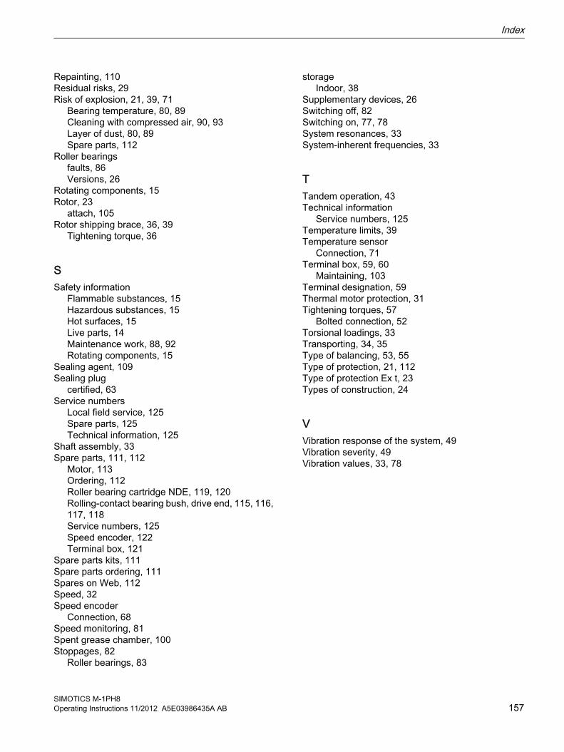
Repainting, 110Residual risks, 29Risk of explosion, 21, 39, 71
Bearing temperature, 80, 89Cleaning with compressed air, 90, 93Layer of dust, 80, 89Spare parts, 112
Roller bearingsfaults, 86Versions, 26
Rotating components, 15Rotor, 23
attach, 105Rotor shipping brace, 36, 39
Tightening torque, 36
SSafety information
Flammable substances, 15Hazardous substances, 15Hot surfaces, 15Live parts, 14Maintenance work, 88, 92Rotating components, 15
Sealing agent, 109Sealing plug
certified, 63Service numbers
Local field service, 125Spare parts, 125Technical information, 125
Shaft assembly, 33Spare parts, 111, 112
Motor, 113Ordering, 112Roller bearing cartridge NDE, 119, 120Rolling-contact bearing bush, drive end, 115, 116, 117, 118Service numbers, 125Speed encoder, 122Terminal box, 121
Spare parts kits, 111Spare parts ordering, 111Spares on Web, 112Speed, 32Speed encoder
Connection, 68Speed monitoring, 81Spent grease chamber, 100Stoppages, 82
Roller bearings, 83
storageIndoor, 38
Supplementary devices, 26Switching off, 82Switching on, 77, 78System resonances, 33System-inherent frequencies, 33
TTandem operation, 43Technical information
Service numbers, 125Temperature limits, 39Temperature sensor
Connection, 71Terminal box, 59, 60
Maintaining, 103Terminal designation, 59Thermal motor protection, 31Tightening torques, 57
Bolted connection, 52Torsional loadings, 33Transporting, 34, 35Type of balancing, 53, 55Type of protection, 21, 112Type of protection Ex t, 23Types of construction, 24
VVibration response of the system, 49Vibration severity, 49Vibration values, 33, 78
Index
SIMOTICS M-1PH8Operating Instructions 11/2012 A5E03986435A AB 157
Index
SIMOTICS M-1PH8158 Operating Instructions 11/2012 A5E03986435A AB

AG EC declaration of Conformity 1PH8 35AA Mounting instructions Ziehl-Abegg ext. fan (Ex-machine)AD EC declaration of Conformity 1PH8

Siemens AGIndustry SectorDrive Technologies and Industry AutomationP.O. Box 484890327 NUREMBERGGERMANY
www.siemens.com/automation