Shifting Control and Analysis of Dual Clutch Transmission ... · DTC (Dual Clutch Transmission) is...
12
International Journal of Control and Automation Vol.8, No.12 (2015), pp.241-252 http://dx.doi.org/10.14257/ijca.2015.8.12.22 ISSN: 2005-4297 IJCA Copyright ⓒ 2015 SERSC Shifting Control and Analysis of Dual Clutch Transmission of Automobile Xiaohui Xia Changzhou College of Information Technology, Changzhou, Jiangsu 213164, China [email protected] Abstract According to the DCT structure and principle, the dynamic shifting process of DCT has been analyzed, and the engine and clutch model have been established. The driver intention has been analyzed and distinguished through the fuzzy control theory, on this basis, gear shift rule has been formulated based on driver intention,separately from the power performance and economy performance. Clutch and engine control strategy for DCT shifting process have been proposed, and shifting control logic also has been drawn up. DCT shifting simulation model has been established based on the MATLAB/Simulink software simulation platform. The simulation result shows that the shifting simulation model in this study meets the requirement, and the shifting control strategy has a good control effect. Keywords: automobile, dual clutch transmission; driver intention; gear shift rule; control strategy 1. Introduction In the automotive industry, the automatic transmission has long been regarded as a substitute for manual transmission. As a key performance indicator of automobile, the economic performance of vehicle fuels has been gradually valued, and the control strategy of automobile’s automatic transmission is very important. The development trend of automatic transmission is mainly reflected in such aspects as excellent economy and comfort of driving and so on. To select the appropriate gear through the cooperation between the intention of the driver and the controller of the vehicle, low fuel consumption can be realized in most operation cases of the engine, while the control of the transmission of the conventional automatic transmission is realized through the control of torque converter and a planetary gear set. Though after years of improvement, the efficiency of mechanical transmission is still lower than that of the manual transmission. Therefore, the primary goal of the automotive industry is to improve the mechanical efficiency, and at the same time, to ensure the comfort and high quality of automatic gearshift [1-2]. DTC (Dual Clutch Transmission) is a new type of automatic transmission device in the field of automotive automatic transmission. It realizes power transmission and interruption, and shifting without power interruption through respective connection between the two transmission shaft and two clutches. AAAA also combines the advantages of manual transmission and traditional torque mechanic transmission so as to equip the vehicle with the same convenience and comfort with manual transmission vehicles, but better fuel economy [3-4]. Shift control is the key technology of DCT vehicles, and an important index to measure the driving comfort of vehicles, therefore, to carry out targeted shift analysis and control of the DCT seems quite necessary.
Transcript of Shifting Control and Analysis of Dual Clutch Transmission ... · DTC (Dual Clutch Transmission) is...
International Journal of Control and Automation
Vol.8, No.12 (2015), pp.241-252
http://dx.doi.org/10.14257/ijca.2015.8.12.22
ISSN: 2005-4297 IJCA
Copyright ⓒ 2015 SERSC
Shifting Control and Analysis of Dual Clutch Transmission of
Automobile
Xiaohui Xia
Changzhou College of Information Technology, Changzhou, Jiangsu 213164,
China
Abstract
According to the DCT structure and principle, the dynamic shifting process of DCT
has been analyzed, and the engine and clutch model have been established. The driver
intention has been analyzed and distinguished through the fuzzy control theory, on this
basis, gear shift rule has been formulated based on driver intention,separately from the
power performance and economy performance. Clutch and engine control strategy for
DCT shifting process have been proposed, and shifting control logic also has been drawn
up. DCT shifting simulation model has been established based on the MATLAB/Simulink
software simulation platform. The simulation result shows that the shifting simulation
model in this study meets the requirement, and the shifting control strategy has a good
control effect.
Keywords: automobile, dual clutch transmission; driver intention; gear shift rule;
control strategy
1. Introduction
In the automotive industry, the automatic transmission has long been regarded as a
substitute for manual transmission. As a key performance indicator of automobile, the
economic performance of vehicle fuels has been gradually valued, and the control strategy
of automobile’s automatic transmission is very important. The development trend of
automatic transmission is mainly reflected in such aspects as excellent economy and
comfort of driving and so on.
To select the appropriate gear through the cooperation between the intention of the
driver and the controller of the vehicle, low fuel consumption can be realized in most
operation cases of the engine, while the control of the transmission of the conventional
automatic transmission is realized through the control of torque converter and a planetary
gear set. Though after years of improvement, the efficiency of mechanical transmission is
still lower than that of the manual transmission. Therefore, the primary goal of the
automotive industry is to improve the mechanical efficiency, and at the same time, to
ensure the comfort and high quality of automatic gearshift [1-2].
DTC (Dual Clutch Transmission) is a new type of automatic transmission device in the
field of automotive automatic transmission. It realizes power transmission and
interruption, and shifting without power interruption through respective connection
between the two transmission shaft and two clutches. AAAA also combines the
advantages of manual transmission and traditional torque mechanic transmission so as to
equip the vehicle with the same convenience and comfort with manual transmission
vehicles, but better fuel economy [3-4]. Shift control is the key technology of DCT
vehicles, and an important index to measure the driving comfort of vehicles, therefore, to
carry out targeted shift analysis and control of the DCT seems quite necessary.
International Journal of Control and Automation
Vol.8, No.12 (2015)
242 Copyright ⓒ 2015 SERSC
According to the characteristics of DCT synchronizer which can be pre-engaged in the
shift, under the premise of ensuring the accurate realization of the synchronizer’s function,
Yang Weibin [5] put forward the control law of DCT synchronizer, achieving accurate
control of synchronizer, but he did not take into account the control of clutch; Ma Jin [6]
took the up shift of Block 1 to Block2 as an example to describe the DCT shift process,
and put forward the control method to improve shift quality according to the clutch
engaging speed and engaging time, which has obtained certain results, but has not involve
the driver intention, nor economic and dynamic effects were representative; Zhao Zhiguo
[7] conducted shift researches targeted at a five speed dry dual clutch transmission to
discusses the torque coordinated control between the engine and DCT. Considering the
characteristics of the physical structures, they established 5 degrees of freedom shifting
dynamics equation, and the results showed that the proposed torque coordinated control
strategy based on models reflected the driver intention of shifting, which improved the
shift quality of DCT, but the control structure was relatively complex.
Aiming at a five rates wet DTC, this paper conducts dynamics analysis of the DCT
shifting process and makes model and analysis of key parts; on this basis, it develops a
shift schedule based on driver intention, and makes detailed analysis for gear shifting
process to develop a shift control strategy; finally, based on the MATLAB/Simulink
simulation platform, it builds DCT shift model and conducts simulation test to verify the
validity of the shift control strategies.
2. Structure and Principle of DCT
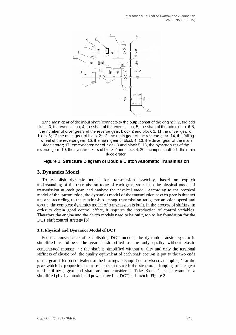
Structure diagram of is as shown in Figure 1. The structure has 5 forward gear blocks
and 1 reverse gear block, and two clutches respectively control the odd and even gear
block. Similar with the traditional manual gear box structure, it includes helical
cylindrical gear set and the synchronizer gear set, wherein Block 1 adopts the connection
between one-way clutch and the input shaft as the constant mesh gear pair. Two clutches
couples with input shaft through the transmission gear pair. Therefore, the two clutches
can be engaged with the motor, by controlling the switch between the two clutches
(isolating the off going clutch, and at the same time engaging the ongoing clutch), to
complete the shift.
International Journal of Control and Automation
Vol.8, No.12 (2015)
Copyright ⓒ 2015 SERSC 243
1,the main gear of the input shaft (connects to the output shaft of the engine); 2, the odd clutch;3, the even clutch; 4, the shaft of the even clutch; 5, the shaft of the odd clutch; 6-8,
the number of diver gears of the reverse gear, block 2 and block 3; 11 the driver gear of block 5; 12 the main gear of block 2; 13, the main gear of the reverse gear; 14, the falling
wheel of the reverse gear; 15, the main gear of block 4; 16, the driver gear of the main decelerator; 17, the synchronizer of block 3 and block 5; 18, the synchronizer of the
reverse gear; 19, the synchronizers of block 2 and block 4; 20, the input shaft; 21, the main decelerator.
Figure 1. Structure Diagram of Double Clutch Automatic Transmission
3. Dynamics Model
To establish dynamic model for transmission assembly, based on explicit
understanding of the transmission route of each gear, we set up the physical model of
transmission at each gear, and analyze the physical model. According to the physical
model of the transmission, the dynamics model of the transmission at each gear is thus set
up, and according to the relationship among transmission ratio, transmission speed and
torque, the complete dynamics model of transmission is built. In the process of shifting, in
order to obtain good control effect, it requires the introduction of control variables.
Therefore the engine and the clutch models need to be built, too to lay foundation for the
DCT shift control strategy [8].
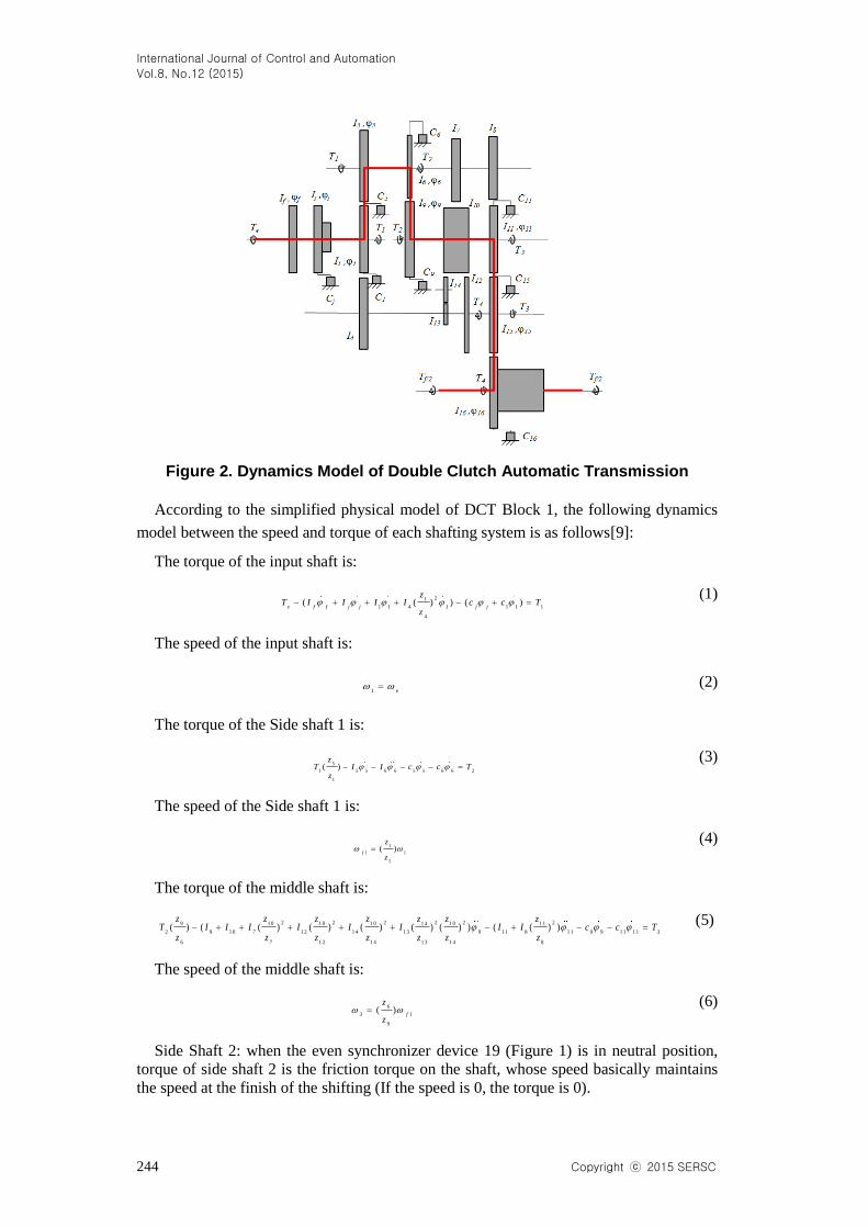
3.1. Physical and Dynamics Model of DCT
For the convenience of establishing DCT models, the dynamic transfer system is
simplified as follows: the gear is simplified as the only quality without elastic
concentrated moment iI ; the shaft is simplified without quality and only the torsional
stiffness of elastic rod, the quality equivalent of each shaft section is put to the two ends
of the gear; friction equivalent at the bearings is simplified as viscous damping iC at the
gear which is proportionate to transmission speed; the structural damping of the gear
mesh stiffness, gear and shaft are not considered. Take Block 1 as an example, a
simplified physical model and power flow line DCT is shown in Figure 2.
International Journal of Control and Automation
Vol.8, No.12 (2015)
244 Copyright ⓒ 2015 SERSC
Figure 2. Dynamics Model of Double Clutch Automatic Transmission
According to the simplified physical model of DCT Block 1, the following dynamics
model between the speed and torque of each shafting system is as follows[9]:
The torque of the input shaft is:
21
1 1 4 1 1 1 1
4
( ( ) ) ( )e f f j j j j
zT I I I I c c T
z
(1)
The speed of the input shaft is:
1 e (2)
The torque of the Side shaft 1 is:
5
1 5 5 6 6 5 5 6 6 2
1
( )z
T I I c c Tz
(3)
The speed of the Side shaft 1 is:
1
1 1
5
( )f
z
z
(4)
The torque of the middle shaft is:
2 2 2 2 2 29 1 0 1 0 1 0 1 01 4 1 1
2 9 1 0 7 1 2 1 4 1 3 9 1 1 8 1 1 9 9 1 1 1 1 3
6 7 1 2 1 4 1 3 1 4 8
( ) ( ( ) ( ) ( ) ( ) ( ) ) ( ( ) )z z z z zz z
T I I I I I I I I c c Tz z z z z z z
(5)
The speed of the middle shaft is:
6
3 1
9
( )f
z
z
(6)
Side Shaft 2: when the even synchronizer device 19 (Figure 1) is in neutral position,
torque of side shaft 2 is the friction torque on the shaft, whose speed basically maintains
the speed at the finish of the shifting (If the speed is 0, the torque is 0).
International Journal of Control and Automation
Vol.8, No.12 (2015)
Copyright ⓒ 2015 SERSC 245
The torque of idler wheel 15 is:
1 5
3 1 5 1 5 1 5 1 5 4
1 1
( )z
T I c Tz
(7)
The torque of idler wheel 15 is:
1 1
1 5 3
1 5
( )z
z
(8)
The torque of block 16 driven by differential:
1 6
4 1 6 1 6 1 6 1 6
1 5
( )f
zT I c T
z
(9)
The torque of block 16 driven by differential:
1 5
1 6 1 5
1 6
( )z
z
(10)
Among them, e
T 、f
I
are respectively the engine output torque, the engine crankshaft
(including flywheel), the output shaft and the equivalent moment of inertia of the clutch
driving plate; f
is the angular displacement of f
I ; j j j
I C、 、 are respectively the
equivalent moment of inertia of active part on the clutch driven plate damper, angular
displacement and the viscous damping, 1
T 、2
T 、3 4 2f
T T T、 、 are respectively the transmission
torque of each component on the transmission route at block 1 power,
1 4 5 6 7 8 9 1 0 1 1 1 2 1 3I I I I I I I I I I I、 、 、 、 、 、 、 、 、 、 、
1 4 1 5 1 6I I I、 、
are respectively the equivalent moment
of inertia of each key component of the vehicle driving system; 1 5 6 9 1 1 1 5 1 6
、 、 、 、 、 、 are respectively the angular displacement of each component on the transmission route at
block 1 power; and1
C 、5 6 9 1 1 1 5 1 6
C C C C C C、 、 、 、 、 are respectively the viscous damping of
each component on the transmission route of block 1 power.
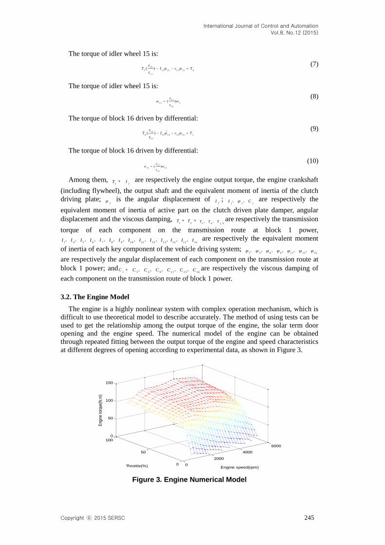
3.2. The Engine Model
The engine is a highly nonlinear system with complex operation mechanism, which is
difficult to use theoretical model to describe accurately. The method of using tests can be
used to get the relationship among the output torque of the engine, the solar term door
opening and the engine speed. The numerical model of the engine can be obtained
through repeated fitting between the output torque of the engine and speed characteristics
at different degrees of opening according to experimental data, as shown in Figure 3.
0
2000
4000
6000
0
50
1000
50
100
150
Engine speed(rpm)Throttle(%)
Eng
ine
torq
ue(N
.m)
Figure 3. Engine Numerical Model
International Journal of Control and Automation
Vol.8, No.12 (2015)
246 Copyright ⓒ 2015 SERSC
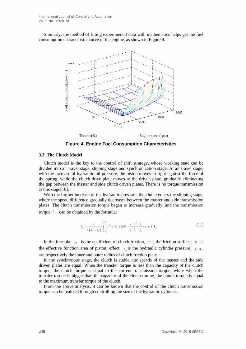
Similarly, the method of fitting experimental data with mathematics helps get the fuel
consumption characteristic curve of the engine, as shown in Figure 4.
Throttle(%) Engine speed(rpm)
Figure 4. Engine Fuel Consumption Characteristics
3.3. The Clutch Model
Clutch model is the key to the control of shift strategy, whose working state can be
divided into air travel stage, slipping stage and synchronization stage. At air travel stage,
with the increase of hydraulic oil pressure, the piston moves to fight against the force of
the spring, while the clutch drive plate moves to the driven plate, gradually eliminating
the gap between the master and side clutch driven plates. There is no torque transmission
at this stage[10].
With the further increase of the hydraulic pressure, the clutch enters the slipping stage,
where the speed difference gradually decreases between the master and side transmission
plates. The clutch transmission torque began to increase gradually, and the transmission
torque clT can be obtained by the formula:
2
1
2 3 3
2 2 1
2 22 2
2 102 1
2
3c l
R
c l c l
R
T z SR Rz
r P S d r d PR RR R
(11)
In the formula: is the coefficient of clutch friction, z is the friction surface; S is
the effective function area of piston; effect; c l
P is the hydraulic cylinder pressure; 1 2,R R
are respectively the inner and outer radius of clutch friction plate.
In the synchronous stage, the clutch is stable, the speeds of the master and the side
driven plates are equal. When the transfer torque is less than the capacity of the clutch
torque, the clutch torque is equal to the current transmission torque, while when the
transfer torque is bigger than the capacity of the clutch torque, the clutch torque is equal
to the maximum transfer torque of the clutch.
From the above analysis, it can be known that the control of the clutch transmission
torque can be realized through controlling the size of the hydraulic cylinder.
Fu
el c
on
sum
pti
on
(g/k
w.h
-1)
International Journal of Control and Automation
Vol.8, No.12 (2015)
Copyright ⓒ 2015 SERSC 247
4. The Integrated Control of the Shifting
Through the fuzzy control method, the driver intention can be identified, and the shift
schedule can be made and amended according to driver intention. On this basis, the DCT
shift process is analyzed in detail and the corresponding control methods are made.
4.1. Identification of the Driver Intention
In the running of vehicles, intelligent control system hopes to be able to best meet the
driver's different driving intention, and at the same time avoid frequent shifting and cyclic
shift so as to avoid affecting the life of the clutch and synchronizer. Therefore, to identify
the driver intention is very important. According to the traditional driving experience,
driving intentions can be divided into parking, deceleration, cruise, acceleration and acute
acceleration.
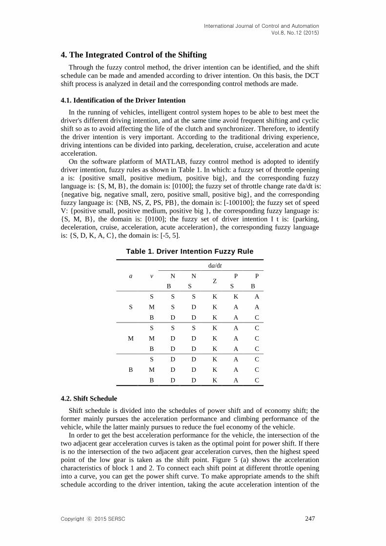
On the software platform of MATLAB, fuzzy control method is adopted to identify
driver intention, fuzzy rules as shown in Table 1. In which: a fuzzy set of throttle opening
a is: {positive small, positive medium, positive big}, and the corresponding fuzzy
language is: {S, M, B}, the domain is: [0100]; the fuzzy set of throttle change rate da/dt is:
{negative big, negative small, zero, positive small, positive big}, and the corresponding
fuzzy language is: {NB, NS, Z, PS, PB}, the domain is: [-100100]; the fuzzy set of speed
V: {positive small, positive medium, positive big }, the corresponding fuzzy language is:
{S, M, B}, the domain is: [0100]; the fuzzy set of driver intention I t is: {parking,
deceleration, cruise, acceleration, acute acceleration}, the corresponding fuzzy language
is: {S, D, K, A, C}, the domain is: [-5, 5].
Table 1. Driver Intention Fuzzy Rule
a v
da/dt
N
B
N
S Z
P
S
P
B
S
S S S K K A
M S D K A A
B D D K A C
M
S S S K A C
M D D K A C
B D D K A C
B
S D D K A C
M D D K A C
B D D K A C
4.2. Shift Schedule
Shift schedule is divided into the schedules of power shift and of economy shift; the
former mainly pursues the acceleration performance and climbing performance of the
vehicle, while the latter mainly pursues to reduce the fuel economy of the vehicle.
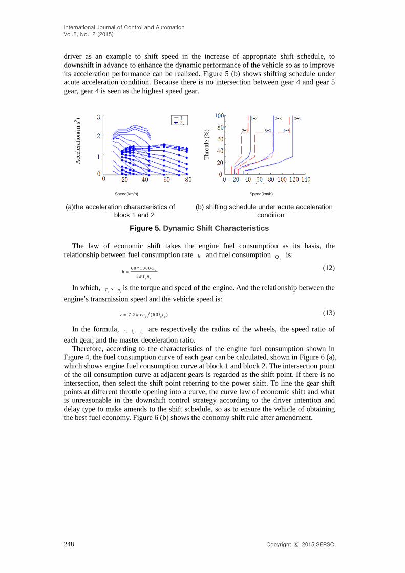
In order to get the best acceleration performance for the vehicle, the intersection of the
two adjacent gear acceleration curves is taken as the optimal point for power shift. If there
is no the intersection of the two adjacent gear acceleration curves, then the highest speed
point of the low gear is taken as the shift point. Figure 5 (a) shows the acceleration
characteristics of block 1 and 2. To connect each shift point at different throttle opening
into a curve, you can get the power shift curve. To make appropriate amends to the shift
schedule according to the driver intention, taking the acute acceleration intention of the
International Journal of Control and Automation
Vol.8, No.12 (2015)
248 Copyright ⓒ 2015 SERSC
driver as an example to shift speed in the increase of appropriate shift schedule, to
downshift in advance to enhance the dynamic performance of the vehicle so as to improve
its acceleration performance can be realized. Figure 5 (b) shows shifting schedule under
acute acceleration condition. Because there is no intersection between gear 4 and gear 5
gear, gear 4 is seen as the highest speed gear.
Speed(km/h) Speed(km/h)
(a)the acceleration characteristics of (b) shifting schedule under acute acceleration block 1 and 2 condition
Figure 5. Dynamic Shift Characteristics
The law of economic shift takes the engine fuel consumption as its basis, the
relationship between fuel consumption rate b and fuel consumption e
Q is:
6 0 * 1 0 0 0
2
e
e e
Qb
T n
(12)
In which, e
T 、e
n is the torque and speed of the engine. And the relationship between the
engine’s transmission speed and the vehicle speed is:
7 .2 (6 0 )e n o
v rn i i (13)
In the formula, n o
r i i、 、 are respectively the radius of the wheels, the speed ratio of
each gear, and the master deceleration ratio.
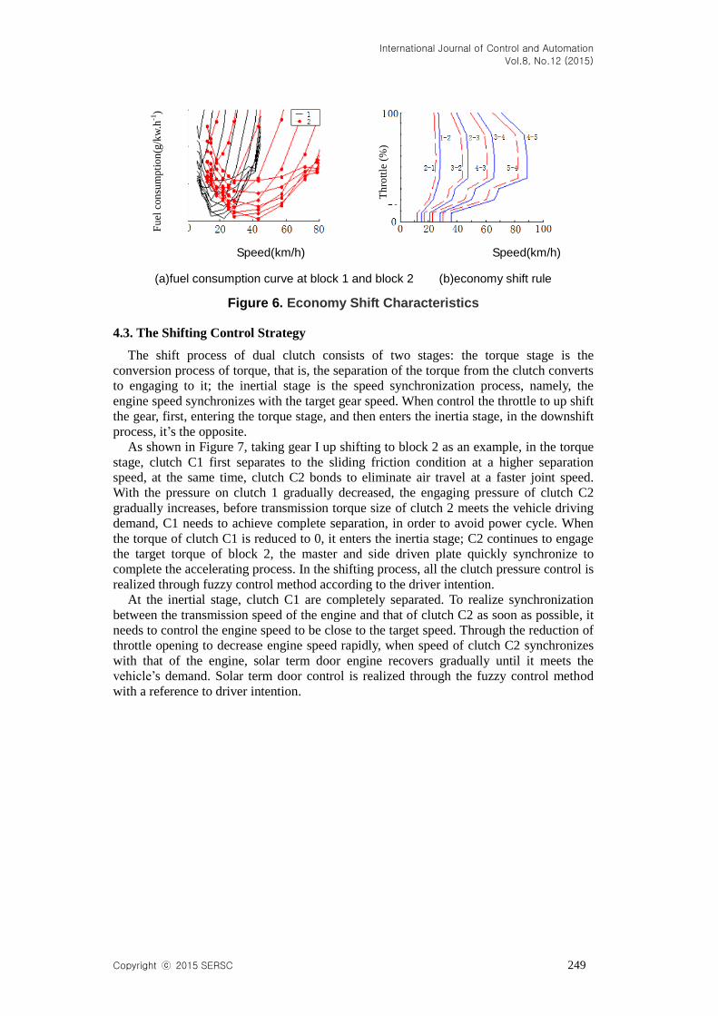
Therefore, according to the characteristics of the engine fuel consumption shown in
Figure 4, the fuel consumption curve of each gear can be calculated, shown in Figure 6 (a),
which shows engine fuel consumption curve at block 1 and block 2. The intersection point
of the oil consumption curve at adjacent gears is regarded as the shift point. If there is no
intersection, then select the shift point referring to the power shift. To line the gear shift
points at different throttle opening into a curve, the curve law of economic shift and what
is unreasonable in the downshift control strategy according to the driver intention and
delay type to make amends to the shift schedule, so as to ensure the vehicle of obtaining
the best fuel economy. Figure 6 (b) shows the economy shift rule after amendment.
Acc
eler
atio
n(m
.s2)
Th
rott
le (
%)
International Journal of Control and Automation
Vol.8, No.12 (2015)
Copyright ⓒ 2015 SERSC 249
Speed(km/h) Speed(km/h)
(a)fuel consumption curve at block 1 and block 2 (b)economy shift rule
Figure 6. Economy Shift Characteristics
4.3. The Shifting Control Strategy
The shift process of dual clutch consists of two stages: the torque stage is the
conversion process of torque, that is, the separation of the torque from the clutch converts
to engaging to it; the inertial stage is the speed synchronization process, namely, the
engine speed synchronizes with the target gear speed. When control the throttle to up shift
the gear, first, entering the torque stage, and then enters the inertia stage, in the downshift
process, it’s the opposite.
As shown in Figure 7, taking gear I up shifting to block 2 as an example, in the torque
stage, clutch C1 first separates to the sliding friction condition at a higher separation
speed, at the same time, clutch C2 bonds to eliminate air travel at a faster joint speed.
With the pressure on clutch 1 gradually decreased, the engaging pressure of clutch C2
gradually increases, before transmission torque size of clutch 2 meets the vehicle driving
demand, C1 needs to achieve complete separation, in order to avoid power cycle. When
the torque of clutch C1 is reduced to 0, it enters the inertia stage; C2 continues to engage
the target torque of block 2, the master and side driven plate quickly synchronize to
complete the accelerating process. In the shifting process, all the clutch pressure control is
realized through fuzzy control method according to the driver intention.
At the inertial stage, clutch C1 are completely separated. To realize synchronization
between the transmission speed of the engine and that of clutch C2 as soon as possible, it
needs to control the engine speed to be close to the target speed. Through the reduction of
throttle opening to decrease engine speed rapidly, when speed of clutch C2 synchronizes
with that of the engine, solar term door engine recovers gradually until it meets the
vehicle’s demand. Solar term door control is realized through the fuzzy control method
with a reference to driver intention.
Fu
el c
on
sum
pti
on
(g/k
w.h
-1)
Th
rott
le (
%)
International Journal of Control and Automation
Vol.8, No.12 (2015)
250 Copyright ⓒ 2015 SERSC
Figure 7. Rise Block Feature
4.4. The Logic of Shift Control
Through the formulation of the shift schedule the analysis of and the shifting process,
comprehensive control logic of shifting are established based on DCT. Take block 1 up
shift to block 2 as an example, the comprehensive control logic of shifting is mainly
divided into three parts: shift identification and shifting schedule judgment, torque control
stage and inertial control stage.
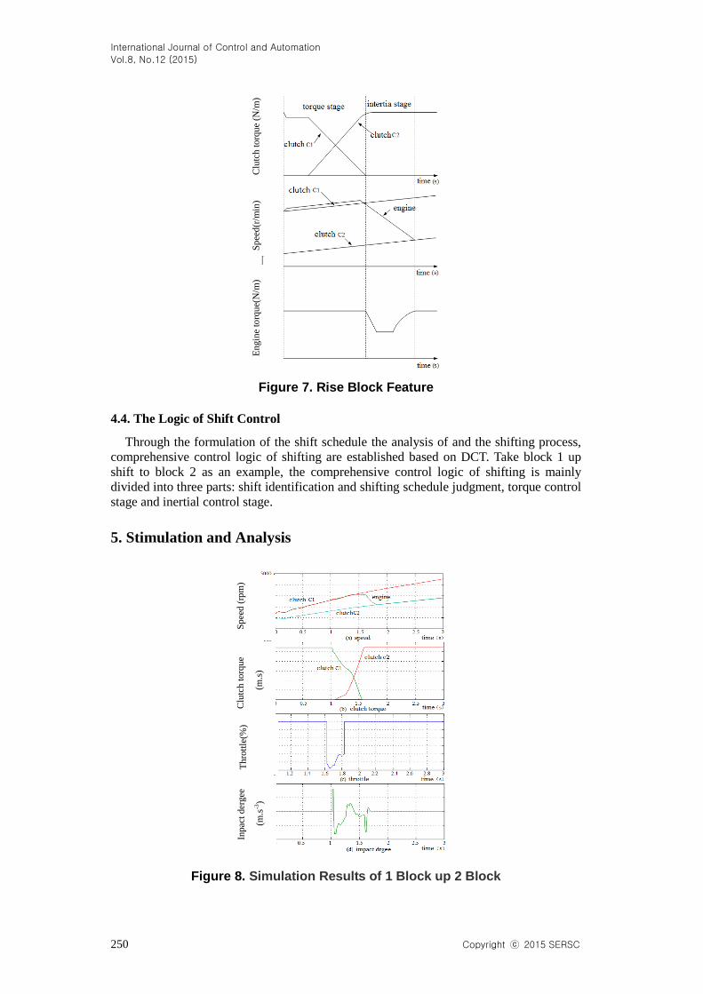
5. Stimulation and Analysis
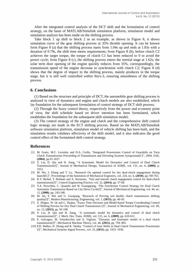
Figure 8. Simulation Results of 1 Block up 2 Block
Eng
ine
torq
ue(
N/m
) S
pee
d(r
/min
) C
lutc
h t
orq
ue
(N/m
)
Inpac
t der
gee
(m.s
-3)
Th
rott
le(%
) C
lutc
h t
orq
ue
(m.s
)
Sp
eed
(rp
m)
International Journal of Control and Automation
Vol.8, No.12 (2015)
Copyright ⓒ 2015 SERSC 251
After the integrated control analysis of the DCT shift and the formulation of control
strategy, on the basis of MATLAB/Simulink simulation platform, simulation model and
simulation analysis has been made on the shifting process.
Take block 1 up shift to block 2 as an example, as shown in Figure 8, it shows
simulation curve of the gear shifting process at 35% throttle opening. It can be known
form Figure 8 (a) that the shifting process starts from 1.04s up and ends at 1.83s with a
duration of 0.79s, the shift time meets requirements; from Figure 8 (b), before clutch C2
achieves the target torque, the torque of clutch C1 has been reduced to 0 to avoid the
power cycle; from Figure 8 (c), the shifting process enters the inertial stage at 1.62s, the
solar term door opening of the engine quickly reduces from 35%, correspondingly, the
transmission speed of the engine decrease to synchronize with clutch C2; Figure 8 (d)
shows that the degree of impact in the shifting process, mainly produces in the torque
stage, but it is still well controlled within 9m/s-3, ensuring smoothness of the shifting
process.
6. Conclusions
(1) Based on the structure and principle of DCT, the automobile gear shifting process is
analyzed in view of dynamics and engine and clutch models are also established, which
lay foundation for the subsequent formulation of control strategy of DCT shift process;
(2) Through the fuzzy control theory, respectively from the power and economy point
of view, the shift schedule based on driver intention has been formulated, which
establishes the foundation for the subsequent shift simulation model;
(3) The control strategy of the engine and clutch and the comprehensive shift control
logic strategy are made in the ECT shifting process. Based on the MATLAB/Simulink
software simulation platform, simulation model of vehicle shifting has been built, and the
simulation results validates affectivity of the shift model, and it also indicates the good
control effect of the formulated shift control strategy.
References
[1] M. Goetz, M.C. Levesley and D.A. Crolla, “Integrated Powertrains Control of Gearshifts on Twin
Clutch Transmissions Proceeding of Transmission and Driveling Systems Symposium[C]”, 2004, SAE,
(2004), pp.01-1637.
[2] Y. Liu, D. Qin and H. Jiang, “A Systematic Model for Dynamics and Control of Dual Clutch
Transmissions[J]”, Journal of Mechanical Design, Transaction of ASME, vol. 131, no. 6, (2009), p.
1012.
[3] M. Wu, J. Zhang and T. Lu, “Research On optimal control for dry dual-clutch engagement during
launch[C]”, Proceedings of the Institution of Mechanical Engineers, vol. 224, no. 6, (2010), pp.749-763.
[4] K.V. Berkel, T. Hofman and A. Serrarens, “Fast and smooth clutch engagement control for dual-clutch
transmissions[J]”, Control Engineering Practice, vol. 22, (2014), pp. 57-68.
[5] Y.A. Noweibin, C. Quanshi and W. Guangqiang, “The Synchroner Control Strategy for Dual Clutch
Automatie Transmission Based on City Drive Cycle[J]”, Journal of Mechanical Engineering, vol. 44, no.
12, (2008), pp. 243-248.
[6] M. Jin, S. Wei and U. Guoqiang, “Research of Proving wet double clutch transmission shifting
quality[J]”, Modern.Manufacturing, Engineering, vol. 1, (2013), pp. 46-50.
[7] Z. Zhiguo, W. Qi and C. Haijun, “Fuzzy Time Decision and Model-based Torque Coordinating Control
of Shifting Process for Dry Dual Clutch Transmission [J]”, Journal of Mechanical Engineering, vol. 49,
no. 12, (2013), pp. 92-108.
[8] Y. Liu, D. Qin and H. Jiang, “A systematic model for dynamics and control of dual clutch
transmissions[J]”, J. Mech. Des. Trans. ASME, vol. 131, no. 6, (2009), pp. 610-612.
[9] E. Galvagno, M. Velardocchia and A. Vigliani, “Dynamic and kinematic model of a dual clutch
transmission[J]”, Mechanical Machine Theory, vol. 46, (2011), pp. 794–805.
[10] P.D. Walker, N. Zhang and R. Tamba, “Control of Gear Shifts in Dual Clutch Transmission Powertrains
[J]”, Mechanical Systems Signal Process., vol. 25, (2011), pp. 1923–1936.

International Journal of Control and Automation
Vol.8, No.12 (2015)
252 Copyright ⓒ 2015 SERSC
Author
Xiaohui Xia, is a graduate student in Nanjing University of
Science & Technology, majoring in applied math. She was
graduated and obtained the bachelor's degree in College of Applied
Math, Nanjing University of Science & Technology.