The OBZ 7-speed Dual Clutch S tronic Transmission in the ...The OBZ 7-speed dual clutch transmission...
81
The OBZ 7-speed Dual Clutch S tronic Transmission in the 2017 R8 Self Study Program 950173
Transcript of The OBZ 7-speed Dual Clutch S tronic Transmission in the ...The OBZ 7-speed dual clutch transmission...

The OBZ 7-speed Dual Clutch S tronic Transmission in the 2017 R8
Self Study Program 950173

ii
Audi of America, LLC Service Training Created in the U.S.A. Created 11/2016 Course Number 950173
©2016 Audi of America, LLC
All rights reserved. Information contained in this manual is based on the latest information available at the time of printing and is subject to the copyright and other intellectual property rights of Audi of America, LLC., its affiliated companies and its licensors. All rights are reserved to make changes at any time without notice. No part of this document may be reproduced, stored in a retrieval system, or transmitted in any form or by any means, electronic, mechanical, photocopying, recording or otherwise, nor may these materials be modified or reposted to other sites without the prior expressed written permission of the publisher.All requests for permission to copy and redistribute information should be referred to Audi of America, LLC.
Always check Technical Bulletins and the latest electronic service repair literature for information that may supersede any information included in this booklet.
Revision:11/2016

iii
Note
Reference
Introduction ......................................................................................1Overview .................................................................................................................................................................... 2
Selector mechanism ...........................................................................4Component overview ................................................................................................................................................ 5Selector lever longitudinal lock ............................................................................................................................... 8Selector lever transverse lock .................................................................................................................................. 9
Transmission functions .....................................................................12Auto-P function .......................................................................................................................................................12Tip-shifting in D/S ...................................................................................................................................................12Activating transmission setting N (holding P-OFF setting) ................................................................................12Launch control program ........................................................................................................................................12Special features of the 2017 R8 ............................................................................................................................13Audi drive select – transmission settings .............................................................................................................14
Gearbox assemblies ..........................................................................16Specifications ..........................................................................................................................................................16Overview and features ............................................................................................................................................16Component overview ..............................................................................................................................................20Gear set/gear train configuration .........................................................................................................................22Dual clutch ..............................................................................................................................................................24Gear train and gear set ..........................................................................................................................................28Gear shifting and gear-shift actuators .................................................................................................................30Power transmission path in gearboxes ................................................................................................................32Parking lock – mechanical function ......................................................................................................................36Parking lock – electro-hydraulic function .............................................................................................................38Parking lock emergency release ............................................................................................................................44Oil system and ATF supply .....................................................................................................................................46Oil level ....................................................................................................................................................................48Lubrication and cooling of the gear train .............................................................................................................50ATF temperature management .............................................................................................................................52
Transmission control ........................................................................54Component overview ..............................................................................................................................................54Dual-Clutch Transmission Mechatronic ................................................................................................................56Auxiliary hydraulic module ....................................................................................................................................62Parking lock module ...............................................................................................................................................63Transmission control modules ..............................................................................................................................65Sensors and information .......................................................................................................................................66Function diagram ...................................................................................................................................................72Hydraulic circuit diagram .......................................................................................................................................74
Knowledge assessment ....................................................................76
The eSelf-Study Program (eSSP) teaches a basic understanding of the design and mode of operation of new models, new automotive components or new technologies. It is not a repair manual! Figures are given for explanatory purposes only and refer to the data valid at the time of preparation of the SSP. This content is not updated. For further information about maintenance and repair work, always refer to the current technical literature.

iv

1
643_002
The new 0BZ S tronic 7-speed dual clutch transmission is a truly sport-oriented gear box. Shifting occurs virtually without interrupting the power transmission.
The seven speeds provide a wide spread of ratios which reduce fuel consumption while retaining a close ratio con-figuration for better acceleration. It offers agility and easy gear shifting to meet customer expectations in terms of handling dynamics and driver convenience.
To review the basic functions of a dual clutch transmission with electro-hydraulic controls, please refer to eSelf-Study Program 951403, The 02E Direct Shift Gearbox, Design and Function.
Learning objectives of this eSelf-Study Program:
After you have completed this eSelf-Study Program, you will be able to answer the following questions:
› What is the design of the 0BZ 7-speed dual clutch transmission? › How does the 0BZ 7-speed dual clutch transmission function? › How does the 0BZ 7-speed dual clutch transmission differ from the dual clutch transmission we are already familiar with?
Introduction

2
Overview
The OBZ 7-speed dual clutch transmission is being offered for the first time in the North American market on the 2017 Audi R8.
The power to the front wheels on the 2017 R8 is via the new OD4 front final drive with an electro-hydraulic multi-plate clutch. For more information about this final drive, please refer to eSelf-Study Program 950163, Front Final Drive OD4 Design and Function.
Automatic Transmission Control Module 2 J1006
The drive response and handling dynamics can be varied using Audi drive select to suit the driver’s preference. See page 14.

3
643_012
643_003
All Wheel Drive Control Module J492
Selector mechanism
Parking lock emergency release mechanism
0D4 front final drive with electro-hydraulically controlled multi-plate clutch eSee Self-Study Program 950163, Front Final Drive OD4 Design and Function for more information.

4
B2B1
A1A2
T-T T+
XX
643_010
643_011
643_012
643_013
The Audi R8 uses the latest-generation Audi B and C series selector mechanism with full "shift-by-wire" functionality.
The operating concept is intuitive and is essentially identi-cal to the familiar operating logic of other Audi automatic transmission models.
The parking lock is normally engaged and disengaged by the Auto-P function but can also be engaged by the driver using the P button. See page 12.
After every operation, the selector lever returns to the normal position of the automatic or tiptronic gate.
Basic shift schematic
Shift schematic
Automatic gate tiptronic gate
Note: An acknowledgement tone sounds when drive position R is engaged.
Automatic gate
tiptronic gate
Possible positions of the selector lever.
The following indications are displayed in the self-diagnosis sequence according to the selector lever position:
X - Normal position in automatic modeT - Normal position in tiptronic mode
A1, A2, B1, B2, T+, and T- are the position indicators in the selector lever position shown in each case
Positions selectable without moving the selector
Selectable drive positions
Normal position of the selector lever and current drive position
Software lock: cancelled by pressing the release button – E681
Software lock: deactivate by pressing the foot brake1)
Mechanical lock by Shift Lock Solenoid N110 – cancelled by pressing Selector Lever Release Button E681
A change in driving direction from D to R and vice versa is only possible at speeds less than approximately 5 mph (8 km/h).
At vehicle speeds above 5 mph (8 km/h), the transmission safety function prevents the change.
Speed-dependent transmission protection function
1) The orange-colored software lock is activated in drive position N after about one second. This allows quick-changing of the drive position from D to R and vice versa without applying the brake. The makes it possible, to free a stuck vehicle by rocking it backwards and forwards and makes it easier to shift driving position when maneuvering.
Selector mechanism

5
Component overview
Handle for selector lever top section
Selector mechanism cover
Selector Lever Release Button E681
Handle for selector lever bottom section with selector lever
Parking Lock Button E816 – P button – Parking Lock Indicator Lamp E3320
Selector Lever Transmission Range Display Y5
Plug connection E
Selector lever
Plug connection C
Plug connection A
Selector mechanism (Selector Lever E313)
Button E681 is used for releasing the selector lever lock. It consists of two shift elements for reliability and diagnos-tics. In the event of a fault, it is considered actuated. The locks marked red and blue (Fig. 643_011) are disabled and a DTC is recorded and then indicated on the instrument cluster. The selector can be moved out of positions P and N by pressing the foot brake.
The P button is for manually engaging the parking lock. The parking lock can only be activated at vehicle speeds less than 0.5 mph (1 km/h). Button E816 has three shift elements for reliability and diagnostics. Its shift status is transferred to Selector Lever Sensor System Control Module J587 via two interfaces. In the event of a fault in E816, a message appears in the instrument cluster and the parking lock can only be engaged by the Auto-P function.
Selector Lever Release Button E681 Parking Lock Button E816
643_014

6
Selector Lever Sensor System Control Module J587
J587 forms a functional unit with Selector Lever Position Sensor G727 and Transverse Selector Lever Lock Sensor G868.
It is responsible for detecting the driver input, analyzing the button signals, communication with Gearbox Control Unit 1 J743, and all selector mechanism control and diagnosis functions. It has the Address Word 81. J587 registers the positions of the selector lever as shown in Figure 643_010 (A2, A1, X, B1, B2, T+, T and T-) and the signals from the buttons E681 and E816, and passes them on to Gearbox Control Unit 1 J743 via the Drivetrain CAN.
Gearbox Control Unit 1 J743 determines the desired trans-mission setting and initiates the appropriate functional operations.
It reports back the current transmission setting to the selec-tor lever sensor module, and then operates Shift Lock Sole-noid N110, the LEDs for Selector Lever Transmission Range Display Y5 and Parking Lock Button K320.
When a transmission setting is selected, there is a brief delay before the relevant transmission setting symbol lights up. 643_015
Schematic diagram of selector mechanism
InformationIf there is a system fault with the selector mechanism, the transmission ranges D and N can be selected by simultaneously pressing the two tiptronic paddles when the vehicle is stationary and the brake applied. See page 13.
The Y adaptor VAS 642 001 allows measurements to be taken between Selector Lever E313 and Selector Lever Transmission Range Display Y5.
VAS 642 001
Selector Lever Sensor System Control Module J587Address Word 81
643_016
Selector mechanism Selector lever
CAN-High
CAN-Low

7
B2
B1A1 A2X
T-
TT+
Selector Lever Position Sensor G727 How selector lever positions are detected:
Selector lever in automatic gate
J587 determines all selector lever positions by means of Selector Lever Position Sensor G727. G727 consists of two sensors – one sensor for the automatic gate and one sensor for the tiptronic gate.
The longitudinal and transverse movements of the selector lever are transmitted to a slider with two diamond-shaped sender elements. The sender elements affect the magnetic flux in the sensor elements of G727 according to the move-ment of the selector lever. From the sensor signals, Selector Lever Sensor System Control Module J587 generates the following selector lever positions:
› Automatic gate A2 – A1 – X (Normal position) – B1 – B2
› tiptronic gate T+ – T (Normal position) – T-
For more details, see the shift schematic on page 6.
643_017
643_018
Restriction of the selector lever movement to one position forwards (T+) and one position backwards (T-) is achieved by means of the tiptronic gate track of the position engagement mechanism.
Key to schematic diagram of selector mechanism on page 6
E313 Selector LeverE681 Selector Lever Release ButtonE816 Parking Lock ButtonG727 Selector Lever Position SensorG868 Transverse Selector Lever Lock SensorJ587 Selector Lever Sensor System Control ModuleK320 Parking Lock Indicator LampN110 Shift Lock SolenoidV577 Transverse Selector Lever Lock MotorY5 Selector Lever Transmission Range Display
Selector lever in tiptronic gate
Plug connection A
Transverse Selector Lever Lock Sensor G868
Circuit board containing Selector Lever Sensor System Control Module J587, Transverse Selector Lever Lock Sensor G868 and Selector Lever Position Sensor G727.
Selector Lever Position Sensor G727 for automatic gate
Selector Lever Position Sensor G727 for tiptronic gateMagnet for G868
Slider with sender elements for automatic and tiptronic gates
Movement of the base plate together with the slider and sender elements
Basic position
8
B2
B1A1 A2X
Selector lever longitudinal lock
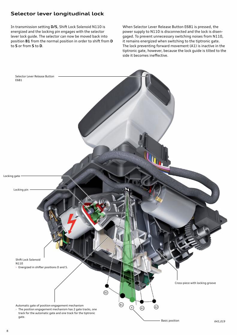
In transmission setting D/S, Shift Lock Solenoid N110 is energized and the locking pin engages with the selector lever lock guide. The selector can now be moved back into position B1 from the normal position in order to shift from D to S or from S to D.
When Selector Lever Release Button E681 is pressed, the power supply to N110 is disconnected and the lock is disen-gaged. To prevent unnecessary switching noises from N110, it remains energized when switching to the tiptronic gate. The lock preventing forward movement (A1) is inactive in the tiptronic gate, however, because the lock guide is tilted to the side it becomes ineffective.
643_019
Selector Lever Release ButtonE681
Locking gate
Shift Lock SolenoidN110 › Energized in shifter positions D and S.
Automatic gate of position engagement mechanism › The position engagement mechanism has 2 gate tracks, one
track for the automatic gate and one track for the tiptronic gate.
Locking pin
Cross-piece with locking groove
Basic position

9
Selector lever transverse lock
Transverse Selector Lever Lock Sensor G868
Transmission setting P/R/N – selector lever transverse lock active
To ensure that the selector lever cannot be inadvertently moved into the tiptronic gate, it is transversely locked in transmission settings P, R and N.
Selector lever transverse lock active
The selector lever is held in the cross-piece. When the trans-verse lock is active, the locking cam is positioned so that it engages in the locking groove of the cross-piece. When the locking cam is in that position, the selector lever cannot be moved into the tiptronic gate.
G868 uses Hall-effect sensors and a sensor magnet that is located at the end of the roller. The sensor magnet affects the signal of G868 according to the rotational position of the roller. From that information Selector Lever Sensor System Control Module J587 determines the position of the roller and thus the status of the selector lever transverse lock.
643_020
Transverse Selector Lever Lock Motor V577
Magnet for G868
Cross-piece with locking groove
Transverse Selector Lever Lock Sensor G868
Worm gear Reciprocating plate
Roller with swash plate, locking cam and sensor magnet
Locking cam

10
2
1
Selector lever transverse lock inactive
Transmission setting D/S – selector lever transverse lock inactive
Selector lever transverse lock cancelling function
To be able to change to the tiptronic gate from transmission setting D or S, the selector lever transverse lock has to be deactivated.
Transverse Selector Lever Lock Motor V577 is oper-ated by Selector Lever Sensor System Control Module J587 until the locking cam is disengaged from the locking groove of the cross-piece.
The cross-piece is then no longer locked and the selector lever can be shifted into the tiptronic gate.
2
1
643_021
643_022
Transverse Selector Lever Lock Sensor G868
Roller with worm gear
From the position of the magnet, the selector lever sensor module detects (with the aid of the sensor G868) that the selector lever transverse lock is not active.
Locking groove clear – the cross-piece and, therefore, the selector lever can move side-ways in the direction of the arrow – the illustration shows the position of the selec-tor lever in the automatic gate.
Locking cam
V577
11
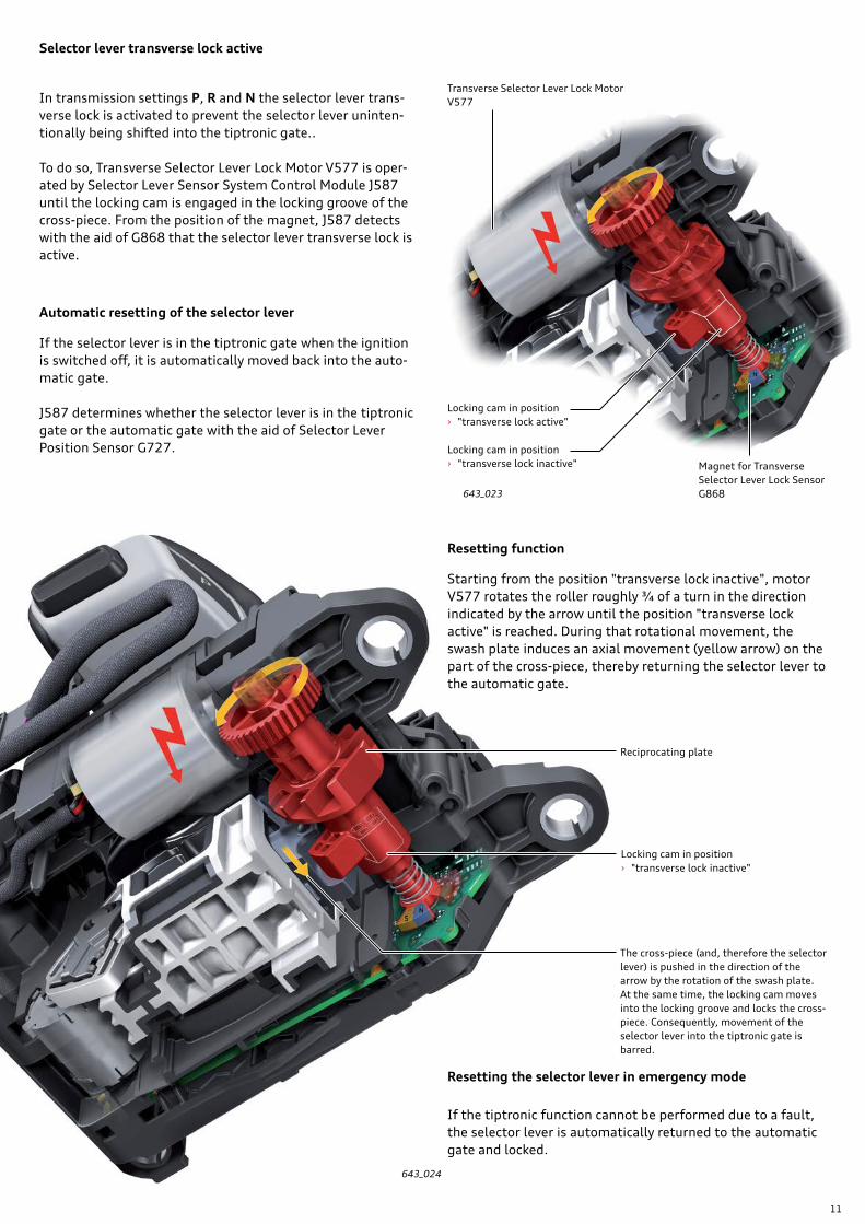
Selector lever transverse lock active
Automatic resetting of the selector lever
Resetting function
Resetting the selector lever in emergency mode
In transmission settings P, R and N the selector lever trans-verse lock is activated to prevent the selector lever uninten-tionally being shifted into the tiptronic gate..
To do so, Transverse Selector Lever Lock Motor V577 is oper-ated by Selector Lever Sensor System Control Module J587 until the locking cam is engaged in the locking groove of the cross-piece. From the position of the magnet, J587 detects with the aid of G868 that the selector lever transverse lock is active.
If the selector lever is in the tiptronic gate when the ignition is switched off, it is automatically moved back into the auto-matic gate.
J587 determines whether the selector lever is in the tiptronic gate or the automatic gate with the aid of Selector Lever Position Sensor G727.
Starting from the position "transverse lock inactive", motor V577 rotates the roller roughly ¾ of a turn in the direction indicated by the arrow until the position "transverse lock active" is reached. During that rotational movement, the swash plate induces an axial movement (yellow arrow) on the part of the cross-piece, thereby returning the selector lever to the automatic gate.
If the tiptronic function cannot be performed due to a fault, the selector lever is automatically returned to the automatic gate and locked.
643_023
643_024
Transverse Selector Lever Lock MotorV577
Locking cam in position › "transverse lock active"
Locking cam in position › "transverse lock inactive"
Locking cam in position › "transverse lock inactive"
The cross-piece (and, therefore the selector lever) is pushed in the direction of the arrow by the rotation of the swash plate. At the same time, the locking cam moves into the locking groove and locks the cross-piece. Consequently, movement of the selector lever into the tiptronic gate is barred.
Magnet for Transverse Selector Lever Lock Sensor G868
Reciprocating plate

12
Auto-P function
Tip-shifting in D/S
Launch control program
Activating transmission setting N (holding P-OFF setting)
The parking lock is operated electro-hydraulically. See page 38. This allows Gearbox Control Module 1 to automatically operate the parking lock, thereby enhancing operating comfort.
The Auto-P function engages the parking lock automatically (P-ON position) if the following conditions are satisfied:
› Vehicle is stationary – vehicle speed less than 0.6 mph (1 km/h).
› One of the transmission settings D, S, R or M is active.
› The engine is switched off – Terminal 15 is off.
On the 2017 Audi R8, the parking lock can also be engaged by the driver by pressing the P button, provided that the vehicle speed is less than 0.6 mph (1 km/h).
The parking lock is disengaged automatically (P-OFF position) if the engine is running and one of the transmission set-tings D, S, R, N or M is selected.
To be able to move the vehicle without the parking lock for a limited amount of time, for example, in a car wash, auto-matic engagement of the parking lock can be prevented.
A condition for this is that the selector mechanism, the P button and the transmission are working properly.
To activate P-OFF, transmission setting N must be selected while the engine is running and then the engine switched off1). When the ignition is turned off, engagement of the parking lock is suppressed for a period of 20 minutes. After 19 minutes the following message is displayed in the instru-ment cluster: “Start engine to remain in N.” along with a warning tone. If this instruction is not followed, the parking lock engages after 20 minutes and the system shuts down.
If a speed signal greater than 0.6 mph (1 km/h) is detected during this time, the period is extended according to the driving time of the vehicle until the system detects that the vehicle has been stationary for at least five minutes.
While the vehicle is stationary with the transmission in P-OFF, power is consumed by the activity of the control modules, bus network operation and the holding solenoid. If the vehicle is stationary for an extended period of time, the battery may become discharged to the extent that the parking lock auto-matically engages. Therefore, if it is necessary to keep the transmission in P-OFF for an extended period, the parking lock emergency release should be actuated.
More information on "Holding transmission setting P-OFF" can be found on page 37.
Manual gear shifts can be executed at any time using the shift paddles on the steering wheel (steering wheel tiptronic controls) in transmission setting D/S. Once the steering wheel tiptronic controls have been used, the transmission remains permanently in manual mode (tiptronic mode).
There are two possible ways of returning to automatic mode:
› Pull the selector lever back one position (position B1).
› Move the selector lever into the tiptronic gate and back into the automatic gate.
The Launch Control Program regulates the maximum accel-eration of the vehicle from a standing start. Please refer to the Owner's Manual for instructions on how to use it and follow the guidance provided.
The Launch Control Program in the Audi R8 has a particularly sporty setup. In addition, forced up-shifts are performed in tiptronic mode. Refer to page 14.
Notes When pulling away with Launch Control active, all vehicle components are heavily stressed. As a result, greater wear may occur.
The number of Launch Control starts performed can be read in the Measuring values.
On the 2017 R8 (100% keyless) the vehicle cannot be locked while P-OFF is active.
Transmission functions

13
Special features of the 2017 R8
Steering wheel tiptronic
The following functions can be selected using the shift paddles on the steering wheel of the 2017 R8.
› If both shift paddles are operated simultaneously while the engine is running, driving position N is selected (both moving and when the vehicle is stationary).
› When the vehicle is stationary, the driver can shift from the transmission settings P, R and N to M1 by operating the Tip+ shift paddle with the brake applied.
› Press-and-hold function: if the driver presses and holds the Tip+ shift paddle while the vehicle is moving, the transmis-sion changes up to the highest possible gear, for example, from 3rd to 5th gear. If the driver presses and holds the Tip– shift paddle, the transmission changes down to the lowest possible gear, for example, from 7th to 3rd gear.
› If a system malfunction occurs in the selector mechanism, the driver can select driving position D with the Tip+ shift paddle when the vehicle is stationary and with the brake pressed. N can be selected by actuating both shift paddles simultaneously. R (reverse gear) is not available.
These additional functions of the tiptronic shift paddles are made possible by the use of redundant backup systems for communicating the shift commands from the shift paddles The shift commands are sent via CAN data bus to Gearbox Control Unit 1 J743 and also by two separate signal lines to Automatic Transmission Control Module 2 J1006. See also schematic diagram on page 72. The information is then, in turn, sent on by CAN data bus to J743.
643_025
Tip - Tip +

14
643_026
snow wet
Performance
last mode drive select
last mode
dry
comfort auto dynamic individual
Performance button
Performance button adjusting ring
Audi drive select button/MMI turn-and-press knob
Terminal 15 changeover
Key:
Audi drive select – transmission settings
The 2017 Audi R8 is equipped with Audi drive select. That means, depending on the vehicle equipment, the driver can experience the performance capabilities and dynamic han-dling characteristics of different vehicle systems.
In addition to the familiar Audi drive select modes – comfort, auto, dynamic and individual – the 2017 R8 has a performance mode. Within performance mode itself there are three sub-modes – snow, wet and dry. Those setups allow the handling systems to be better adapted to the road surface conditions. The Audi drive select handling system utilizes the electronic stability control (ESC) system in perfor-mance mode.
Basic information about Audi drive select on the Audi R8 can be found in eSelf-Study Program 990363, The 2017 Audi R8 Introduction. It explains how the transmission control system reacts to the various Audi drive select modes.
The comfort, auto and dynamic modes
comfort and auto modes are identical regarding transmission setup. The shift points and the gear shifts are comfort-orien-tated.
In dynamic mode the sport program S is selected in the gearbox. In the sport program the shift points are at higher engine speeds and shift times are reduced. This makes for better power delivery and more noticeable gear shifts.
The overview on page 15 shows the effects of the various Audi drive select modes on the transmission setup.
speeds, gear changes are very fast and distinctly perceptible. Performance mode can only be activated and operated using the Performance button the steering wheel. The Performance button allows the driver to activate or deactivate perfor-mance mode directly and in any Audi drive select mode.
Performance mode
Performance mode is standard on the V10 plus and optional on the V10. In performance mode, the transmission setup is very sporty. That means that the transmission works to maxi-mize power delivery from the engine; comfort plays a second-ary role. Gear shifts are performed at very high engine
Please note that the stabilization functions of the ESC and traction control systems are limited when performance mode is activated. You should only activate performance mode if you have the necessary driving skills and the traffic conditions permit. There is a danger of skidding and losing control!
InformationThe following applies to vehicles for the North America region and all other countries from model year '17 on: If performance mode is selected, Gearbox Control Unit 1 switches to tiptronic mode MS+ and automatic mode is not available.

15
comfort autodynamic
= sport program
performanceNo distinction is made between dry, wet and
snow
Driving position1) D M D M S MS MS+
Shift characteristics normal – normal – sporty – –
Automatic upshifting in M mode
– Yes – Yes – No No
Downshift during-kickdown in M mode
– Yes – Yes – No No
Modified accelerator map, increased idling and driveaway speed
normal sporty super sporty
Launch control program No No Yes – with forced up-shift to M and with the most high-performance shift
sequence and fastest gear changes
Blipping the throttle during downshift
No Yes No Yes Yes
Shift sequence/shift time A C A C B C D
Return to automatic mode after actuating the tiptronic shift paddles
No – No – No – –
Engine start/stop mode Yes No
Key to shift sequences/shift times:
Overview of transmission setups available with Audi drive select
Performance button
The Performance button is a touch switch with an adjusting ring. The adjusting ring is used to select the snow, wet and dry modes. Those modes have no effect on the setup of the transmission.
A Comfort-orientated overlapping gear shift with engine torque interventionB Shift-time-orientated overlapping gear shift with maximum engine torque interventionC Fast overlapping gear shift with maximum engine torque intervention – specially adapted for tiptronic operationD Fastest possible overlapping gear shift with maximum engine torque intervention and utilisation of engine inertial torque during
up-shifts
1) The transmission setting is determined by the selector lever setting (D, S, or M) in combination with the choice of Audi drive select mode. M means: tiptronic Manual shift program, MS means: tiptronic Manual Sport shift program , MS+ means: Manual Sport Plus shift program.
643_027
Audi drive select button Performance button with adjusting ring for selecting the snow, wet and dry modes
Audi drive select modes
Transmission setups and functions

16
Specifications
643_038
Designations Manufacturer DL800-7AService 7-speed dual clutch gearbox 0BZSales S tronic
Development/production Audi AG Ingolstadt/VW plant Kassel
Gearbox type Full synchromesh 3-shaft sliding-collar variable-speed gearbox with 7 forward gears and one reverse gear, electro-hydraulically operated for mid-engine concept, with differential lock in the rear final drive and PTO shaft for direct power transmission to the front final drive
Dual clutch Two wet-type multi-plate clutches in an in-line configuration, electro-hydraulically operated and oil-cooled
Control system Mechatronic unit plus 2 additional electro-hydraulic modules (parking lock module and auxiliary hydraulics module) – shift-by-wire actuation with electro-hydraulically operated parking lock (park by wire), Two control module concept for park-by-wire technology and separate clutch cooling for clutches K1 and K2. Automatic mode with various shift programs and tiptronic program for manual gear-shifting.
Ratio configuration › 6+E configuration on the V10 (the 7th gear is a high ratio designed for fuel economy) › 7 speed configuration on V10 plus
Weight 311 lb (141 kg) including ATF and dual-mass flywheel
Overview and features
Gearbox assemblies

17
Transmission ratios for the PTO shaft for the front final drive 0D4 › Basic transmission ratio on V10: 28 : 23 › Dynamic transmission ratio on V10 Plus: 28 : 21
ATF drain and inspection plug with bayonet Dual-Clutch Transmission Mechatronic J743 now participates with Immobilizer system.
Differential lock with modified locking characteristics for front final drive 0D4.
ATF cooler1) with deflector hood (crash guard)
Parking lock emergency release operated from vehicle interior by mechanical cable
1) The overall cooling concept on the 2017 Audi R8 has been redesigned and substantially improved so that no additional ATF cooler (air/oil heat exchanger) is required by either engine variant.
643_036

18
A Electrical connection of Parking Lock Module T16a
B Electrical connection of Auxiliary Hydraulic Module T16b
643_037
Axial alignment of input shaft
597 mm
X
The 0BZ was developed specially for the new MSS platform1). That platform requires a transmission with a short installed length.
Those requirements were essentially achieved by means of the following design features:
› Compact dual clutch with directly adjacent clutches.
› Positioning of the Mechatronic module on the side of the transmission.
› 3-shaft gear-set configuration.
› Positioning of the rear final drive and the PTO shaft for the front final drive.
With an installed length shorter than 23.6 in (600 mm), the OBZ transmission is more than 5.9 in (150 mm) shorter than the R tronic.
Together with the engine's dry-sump lubrication system, it achieves sufficient ground clearance at the same time as providing a low center of gravity for the vehicle while keeping within the baseline limit.
The 0BZ 7-speed dual clutch gearbox is perfectly suited for the new MSS platform1) with mid-engine configuration and quattro drive. That platform is the basis for the 2017 Audi R8 and the Lamborghini Huracán.
1) MSS = Modular Super Sports-car
AC
B
C Electrical connector T16c for Dual-Clutch Transmission Mechatronic J743
X Installation space requirement from axis of transmission input shaft (= crankshaft axis) to bottom of transmission

19

20
Component overview
Electrical connection/circuit board for parking lock module
Parking lock mechanism and parking lock emergency release mechanism
Electro-hydraulic parking lock › Parking lock module
Final drive with differential lock › The locking characteristics have been adapted to the
quattro drive concepts › For more information on the differential lock refer
to eSSP 950123, Audi R8 Power Transmission
Dual clutch

21
643_038
Auxiliary hydraulic module › ATF pump › Electro-hydraulic control unit
Electrical connection for auxiliary hydraulic module
Electrical connection for auxiliary hydraulic module
Electro-hydraulic gearbox control module › Dual-Clutch Transmission Mechatronic
J743 › Gearbox Control Unit 1 J743
Electrical connection of mechatronic unit
Gear set and gear actuator › Hydraulically operated selector plates
Automatic Transmission Control Module 2 J1006
Parking lock gear

22
Gear set/gear train configuration
A dual clutch transmission consists of two gear train subsets and two associated clutches - K1 and K2. Gear train subset 1 carries the uneven gears 1, 3, 5, 7 and gear train subset 2 the even gears 2, 4, 6 and reverse.
In operation, only one gear train subset is transmitting power at a time, while on the other gear train subset the next gear required is pre-engaged. If, for example, the vehicle is accel-erating in 3rd gear, the next gear required is 4th gear on gear train subset 2.
Gear changes are performed by switching power transmission from one clutch to the other. In the above example – changing from 3rd to 4th gear – clutch K2 is engaged while clutch K1 is simultaneously disengaged.
That process is referred to clutch overlap or overlap gear shift-ing. The entire sequence takes place in only a few hundredths of a second. The dual clutch gearbox enables quicker gear shifts which reduce power flow interruption.
Differential gear with differential lock
Spur gear for driving ATF pump
Crankshaft
Dual-mass flywheel for isolating rotational vibration
Front final drive input shaft › The final drive input shaft is also referred to
as the PTO shaft.
Output shaft transmission ratios › Basic transmission ratio on V10: 28 : 23 › Dynamic transmission ratio on V10 Plus: 28 : 21
K2 K1
Rear axle final drive

23
The rear final drive uses bevel gears without hypoid offset. That means that the sliding forces between the meshing teeth are smaller than with bevel gears with hypoid offset. This design enables the use of a common oil system using low-viscosity ATF for all functional transmission sub-assemblies.
The differential has a differential lock design carried over from the R tronic. More detailed information on the differ-ential lock can be found in eSSP 950123, Audi R8 Power Transmission. The locking characteristics have been adapted to suit the all-wheel drive concept of the 2017 R8.
643_039
Output shaft 1
Pinion shaft
Output shaft 2
Input shaft 1
Input shaft 2
2
1
54
63
7
Gearbox unit 1
Gearbox unit 2
R

24
K2 K1
Dual clutch
The dual clutch is the central functional component of the dual clutch transmission. It transmits the torque to the relevant gear train subset.
Design features
The dual clutch consists of two wet-type multi-plate clutches, K1 and K2. The two clutches are mounted in line with each other and have the same dimensions and the same number of plates.
Power transmission path in the dual clutch
The engine torque is transmitted from the dual-mass fly-wheel via the dog clutch to the coupling housing and from there to the clutch housing cover. The clutch cover positively interlocks with the clutch hub. The clutch hub, in turn, is connected to the inner plate carriers of the two clutches. Clutch K1 transmits the torque to its outer plate carrier, which in turn positively interlocks with input shaft 1. Clutch K2 transmits the torque to input shaft 2.
643_040Input shaft 1Driving device Input shaft 2
Clutch carrier
Clutch hub – inner plate carrier
Clutch housing cover
Clutch housing
Reluctor for engine speed sensor
Piston K2
Piston K1MEngine

25
K2
K1
643_041
Ring gear – for starter
Clutch hub – inner plate carrier
Dual mass flywheel Driving device Clutch cover Clutch housing cover
Clutch carrier
Dowel sleeveATF pump drive
Sections through fixed components – gearbox housing
Power transmission path from dog clutch to clutch
26
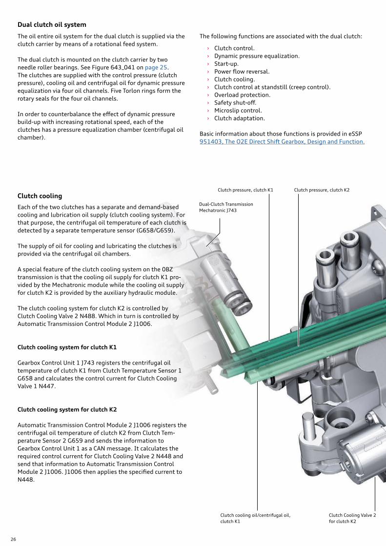
Dual clutch oil system
Clutch cooling
The oil entire oil system for the dual clutch is supplied via the clutch carrier by means of a rotational feed system.
The dual clutch is mounted on the clutch carrier by two needle roller bearings. See Figure 643_041 on page 25. The clutches are supplied with the control pressure (clutch pressure), cooling oil and centrifugal oil for dynamic pressure equalization via four oil channels. Five Torlon rings form the rotary seals for the four oil channels.
In order to counterbalance the effect of dynamic pressure build-up with increasing rotational speed, each of the clutches has a pressure equalization chamber (centrifugal oil chamber).
Each of the two clutches has a separate and demand-based cooling and lubrication oil supply (clutch cooling system). For that purpose, the centrifugal oil temperature of each clutch is detected by a separate temperature sensor (G658/G659).
The supply of oil for cooling and lubricating the clutches is provided via the centrifugal oil chambers.
A special feature of the clutch cooling system on the 0BZ transmission is that the cooling oil supply for clutch K1 pro-vided by the Mechatronic module while the cooling oil supply for clutch K2 is provided by the auxiliary hydraulic module.
The clutch cooling system for clutch K2 is controlled by Clutch Cooling Valve 2 N488. Which in turn is controlled by Automatic Transmission Control Module 2 J1006.
Clutch cooling system for clutch K1
Gearbox Control Unit 1 J743 registers the centrifugal oil temperature of clutch K1 from Clutch Temperature Sensor 1 G658 and calculates the control current for Clutch Cooling Valve 1 N447.
Clutch cooling system for clutch K2
Automatic Transmission Control Module 2 J1006 registers the centrifugal oil temperature of clutch K2 from Clutch Tem-perature Sensor 2 G659 and sends the information to Gearbox Control Unit 1 as a CAN message. It calculates the required control current for Clutch Cooling Valve 2 N448 and send that information to Automatic Transmission Control Module 2 J1006. J1006 then applies the specified current to N448.
The following functions are associated with the dual clutch:
› Clutch control. › Dynamic pressure equalization. › Start-up. › Power flow reversal. › Clutch cooling. › Clutch control at standstill (creep control). › Overload protection. › Safety shut-off. › Microslip control. › Clutch adaptation.
Basic information about those functions is provided in eSSP 951403, The O2E Direct Shift Gearbox, Design and Function.
Dual-Clutch Transmission Mechatronic J743
Clutch pressure, clutch K1 Clutch pressure, clutch K2
Clutch Cooling Valve 2 for clutch K2
Clutch cooling oil/centrifugal oil, clutch K1

27
KD1
KD1
K1
K2
KD2
KD2
KK1
KK1
KK2
KK2
Clutch monitoring
The clutch pressure of the two clutches is continuously monitored by Gearbox Control Unit 1 J743. If the pressure deviates from the specified clutch pressure, the clutch concerned is de-pressurized by means of a safety cut-out. Refer to page 60.
The temperature of the two clutches is continuously moni-tored by J743 and J1006.
Two temperature sensors, G658 and G659, are used to calcu-late the clutch temperature and controlling clutch cooling.
If a centrifugal oil temperature of around approximately 338 °F (170 °C) is exceeded, the instrument cluster displays the warning "Gearbox too hot. Please adjust driving style." and a corresponding DTC is registered in the control module.
643_042
Clutch cooling oil/centrifugal oil, clutch K2Auxiliary hydraulic moduleClutch Cooling Valve 2 for clutch K2
Pressure equalization chamber – centrifugal oil chamber, clutch K1
Pressure equalization chamber – centrifugal oil chamber, clutch K2
Clutch piston, clutch K1
Clutch piston, clutch K2
Pressure chamber K1
Pressure chamber K1
Clutch pressure oil channel, clutch K1
Cooling oil/centrifugal oil channel, clutch K1
Clutch pressure oil channel, clutch K2
Cooling oil/centrifugal oil channel, clutch K2
Key:
Torlon ring

28
Special features
The gear set of the 0BZ transmission has the following special features:
› Reverse gear is implemented without a separate reverse drive gear or reverse shaft.
› The parking lock gear is combined with the sliding collar of gear set R/4 in a single unit.
› There is a separate output shaft for driving the front wheels.
Figure 643_045 opposite shows how the two output shafts 1 and 2, the pinion shaft and the PTO shaft for the front final drive are permanently engaged.
643_043
Pinion shaft
Output shaft 1
Output shaft 2
Input shaft 1Input shaft 2
Sliding collar R/4 with parking lock gear
Front final drive input shaft (PTO)
Gear train and gear set
Different output shaft transmission ratios › Basic transmission ratio on V10: 28 : 23 › Dynamic transmission ratio on V10 Plus: 28 : 21

29
Disengage Reverse gear
The parking lock gear is located on the sliding collar of gear set R/4. The sliding collar, the synchromesh hub and output shaft 1 are locked together rotationally. When the parking lock is engaged, output shaft 1 is locked.
The reversal of rotation direction for reverse gear is achieved by means of the synchronizer gear for 2nd gear. The syn-chronizer gears for 2nd and reverse gears are permanently engaged. In reverse gear, the torque is transmitted from input shaft 2 via the idling synchronizer gear for 2nd gear to the synchronizer gear for reverse gear. The direction of rotation of output shaft 1 is opposite to what it is in the forward gears.
643_044
643_045
Pinion shaft
Output shaft 1
Output shaft 2
Output shaft 2
Output shaft 1
Reverse gear
Input shaft 2
Interconnection of the shafts
2nd gear pinion
Synchro hub
Sliding collar R/4with parking lock gear
30
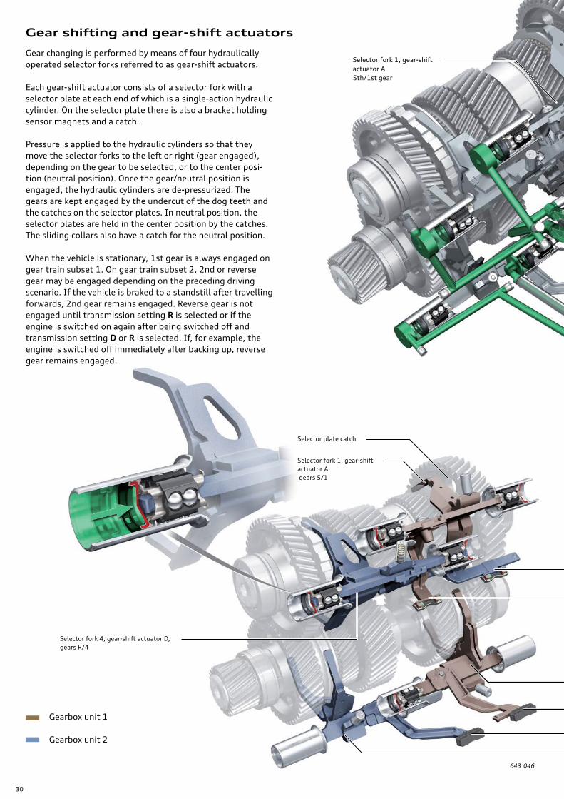
Gear shifting and gear-shift actuators
Gear changing is performed by means of four hydraulically operated selector forks referred to as gear-shift actuators.
Each gear-shift actuator consists of a selector fork with a selector plate at each end of which is a single-action hydraulic cylinder. On the selector plate there is also a bracket holding sensor magnets and a catch.
Pressure is applied to the hydraulic cylinders so that they move the selector forks to the left or right (gear engaged), depending on the gear to be selected, or to the center posi-tion (neutral position). Once the gear/neutral position is engaged, the hydraulic cylinders are de-pressurized. The gears are kept engaged by the undercut of the dog teeth and the catches on the selector plates. In neutral position, the selector plates are held in the center position by the catches. The sliding collars also have a catch for the neutral position.
When the vehicle is stationary, 1st gear is always engaged on gear train subset 1. On gear train subset 2, 2nd or reverse gear may be engaged depending on the preceding driving scenario. If the vehicle is braked to a standstill after travelling forwards, 2nd gear remains engaged. Reverse gear is not engaged until transmission setting R is selected or if the engine is switched on again after being switched off and transmission setting D or R is selected. If, for example, the engine is switched off immediately after backing up, reverse gear remains engaged.
643_046
Selector plate catch
Selector fork 1, gear-shift actuator A, gears 5/1
Selector fork 1, gear-shift actuator A5th/1st gear
Selector fork 4, gear-shift actuator D, gears R/4
Gearbox unit 1
Gearbox unit 2

31
Gear shift monitoring
For the transmission to function perfectly, the exact positions of the selector forks must be known by transmission control module.
Four travel sensors, aided by sensor magnets attached to the selector rods, define the positions of the relevant gear shift actuators/selector forks. Refer to page 68.
643_047
643_102
Sensor magnet for Gear Position Distance Sensor 4 G4901) for gear-shift actuator D for gears R/4
Selector fork 3/gear-shift actuator C, gears 3/7
Sensor magnet for Gear Position Distance Sensor 2 G4881) for gear-shift actuator B for gears 2/6
Sensor magnet for Gear Position Distance Sensor 3 G4891) for gear-shift actuator C for gears 3/7
Sensor magnet for Gear Position Distance Sensor 1 G4871) for gear-shift actuator A for gears 5/1
Selector fork 2/gear-shift actuator B, gears 2/6
In the event of malfunctions or invalid shift positions, the gear train subset concerned is hydraulically disabled by means of the safety cut-out. Refer to page 60.
Due to manufacturing tolerances, the limit positions and synchronization points of each gear have to be learned by Dual-Clutch Transmission Mechatronic J743. This can be done via the VAS Scan Tool.
The measurements taken – actual positions of gear-shift actuator A (B/C/D) – show the gear-shift travel in millime-tres. Refer to page 68.
3rd/4th/5th/6th gear engaged
Neutral position 1st/2nd/7th/Reverse gear engaged
Travel of gear-shift actuator
1) See also page 68.
32
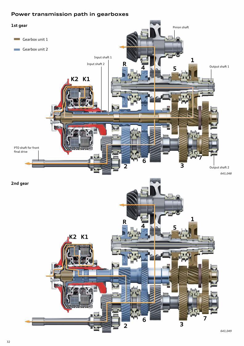
Power transmission path in gearboxes
1st gear
2nd gear
643_048
643_049
2
R
R
2
1
1
5
5
4
4
K2
K2
K1
K1
6
6
3
3
7
7
PTO shaft for front final drive
Pinion shaft
Output shaft 1
Input shaft 1
Input shaft 2
Output shaft 2
Gearbox unit 1
Gearbox unit 2
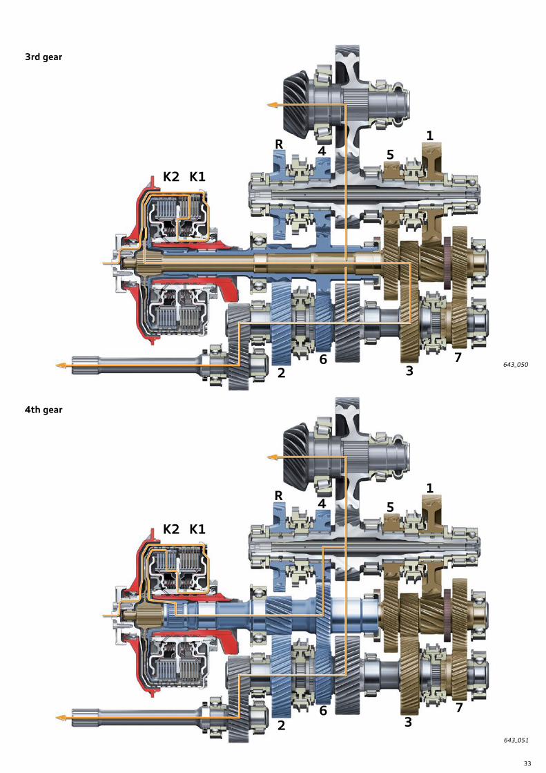
33
3rd gear
4th gear
643_050
643_051
2
R
R
2
1
1
5
5
4
4
K2
K2
K1
K1
6
6
3
3
7
7
Output shaft 1
Output shaft 2
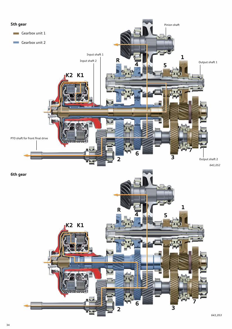
34
5th gear
6th gear
643_052
643_053
Gearbox unit 1
Gearbox unit 2
PTO shaft for front final drive
Pinion shaft
Output shaft 1
Input shaft 1
Input shaft 2
Output shaft 22
R 154
K2 K1
63
7
R
2
154
K2 K1
63
7

35
7th gear
Reverse gear
643_054
643_055
Output shaft 1
Output shaft 2 2
R
R
2
1
1
5
5
4
4
K2
K2
K1
K1
6
6
3
3
7
7
36
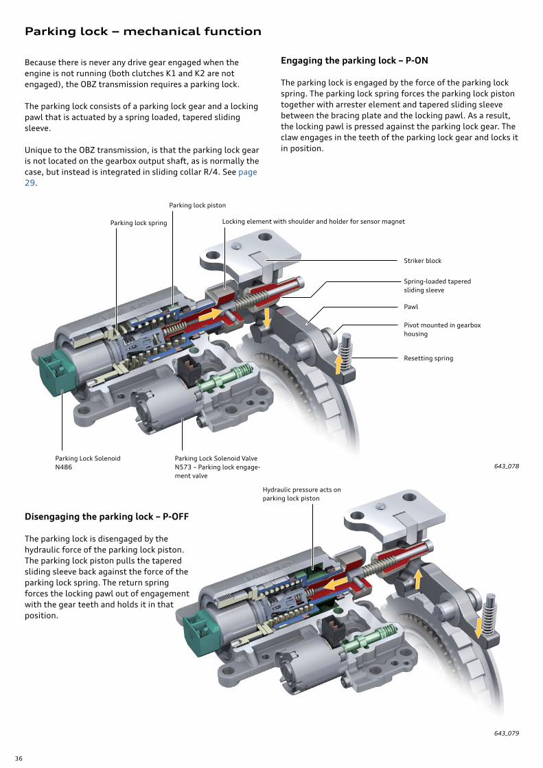
Parking lock – mechanical function
Because there is never any drive gear engaged when the engine is not running (both clutches K1 and K2 are not engaged), the OBZ transmission requires a parking lock.
The parking lock consists of a parking lock gear and a locking pawl that is actuated by a spring loaded, tapered sliding sleeve.
Unique to the OBZ transmission, is that the parking lock gear is not located on the gearbox output shaft, as is normally the case, but instead is integrated in sliding collar R/4. See page 29.
Engaging the parking lock – P-ON
The parking lock is engaged by the force of the parking lock spring. The parking lock spring forces the parking lock piston together with arrester element and tapered sliding sleeve between the bracing plate and the locking pawl. As a result, the locking pawl is pressed against the parking lock gear. The claw engages in the teeth of the parking lock gear and locks it in position.
643_078
Parking lock piston
Parking lock spring
Parking Lock Solenoid N486
Parking Lock Solenoid Valve N573 – Parking lock engage-ment valve
Striker block
Spring-loaded tapered sliding sleeve
Pawl
Pivot mounted in gearbox housing
Resetting spring
643_079
Hydraulic pressure acts on parking lock piston
Disengaging the parking lock – P-OFF
The parking lock is disengaged by the hydraulic force of the parking lock piston. The parking lock piston pulls the tapered sliding sleeve back against the force of the parking lock spring. The return spring forces the locking pawl out of engagement with the gear teeth and holds it in that position.
Locking element with shoulder and holder for sensor magnet

37
N486
643_080
643_081
Engaging the parking lock if pawl and gear do not mesh
1. If the claw of the locking pawl clashes with a tooth of the parking lock gear, the tapered sliding sleeve is still forced between the bracing plate and the locking pawl by the preloaded spring force. The tapered sleeve is spring-loaded and presses the locking pawl against the tooth of the parking lock gear.
2. As soon as the vehicle rolls a little and the parking lock gear rotates slightly, the locking pawl snaps into engagement with the parking lock gear because the tapered sleeve is preloaded by the force of the spring. The parking lock is engaged.
643_082
Tapered sliding sleeve – spring-loaded
Claw and tooth clashing
A - Keeping parking lock disengaged
If the parking lock needs to remain disengaged after the engine is switched off, the parking lock piston has to be held in the P-OFF position by the Parking Lock Solenoid N486.
To hold the lock in position P-OFF, N486 remains energized after the engine is switched off. That means that the arma-ture of N486 remains pulled in against the force of the spring (Figure A).
Holding the parking lock in position P-OFF with Parking Lock Solenoid N486
B - Engaging the parking lock
If N486 is de-energized, the armature of N486 moves out (to the right) under the force of the armature spring. As a result, the ratchet springs are forced apart and release the arrester element of the parking lock piston. The parking lock piston is thus unlocked and the parking lock spring forces the parking lock piston into the P-ON position.
Ratchet spring Arrester element with parking lock piston
Locking element
A B
In that position, the 3 ratchet springs of N486 engage with the locking tip of the arrester element and so lock the parking lock piston in the P-OFF position.
More information on activating the transmission setting P-OFF can be found on page 12.
2nd step
1st step
PistonsPiston springSnap hook
38
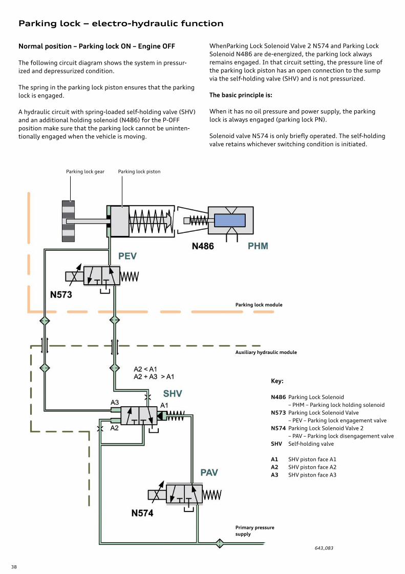
Normal position – Parking lock ON – Engine OFF
The following circuit diagram shows the system in pressur-ized and depressurized condition.
The spring in the parking lock piston ensures that the parking lock is engaged.
A hydraulic circuit with spring-loaded self-holding valve (SHV) and an additional holding solenoid (N486) for the P-OFF position make sure that the parking lock cannot be uninten-tionally engaged when the vehicle is moving.
643_083
Parking lock gear Parking lock piston
Parking lock module
Auxiliary hydraulic module
Primary pressure supply
Parking lock – electro-hydraulic function
WhenParking Lock Solenoid Valve 2 N574 and Parking Lock Solenoid N486 are de-energized, the parking lock always remains engaged. In that circuit setting, the pressure line of the parking lock piston has an open connection to the sump via the self-holding valve (SHV) and is not pressurized.
The basic principle is:
When it has no oil pressure and power supply, the parking lock is always engaged (parking lock PN).
Solenoid valve N574 is only briefly operated. The self-holding valve retains whichever switching condition is initiated.
Key:
N486 Parking Lock Solenoid – PHM – Parking lock holding solenoidN573 Parking Lock Solenoid Valve – PEV – Parking lock engagement valveN574 Parking Lock Solenoid Valve 2 – PAV – Parking lock disengagement valveSHV Self-holding valve
A1 SHV piston face A1A2 SHV piston face A2A3 SHV piston face A3

39
Parking lock module
Auxiliary hydraulic module
Primary pressure supply
Parking lock ON – engine running
Even if the primary pressure is present when the engine is running, the self-holding valve remains in its normal position and keeps connection between the parking lock piston pressure line and the sump open and, therefore, depressur-ized. When P-ON is active, N573 remains energized until the engine is switched off.
That means the connection between the parking lock piston and the sump is open. This prevents unintentional pressure build up that would result from the disengagement of the parking lock.
The self-holding valve, SHV
The SHV has a spring-loaded valve with 3 different-sized piston faces – faces A1, A2 and A3. Depending on the switch-ing position of the solenoid valves N573 and N574, either the primary pressure (equal pressure) or no pressure is acting on those faces. Since the same pressure acts on all the piston faces, different forces result and enable the valve to be moved to the desired setting.
The following relationships apply to the piston faces:1. Face A2 is smaller than face A1.2. Faces A2 and A3 combined are larger than face A1.
A larger face (A) = Greater force
In the situation illustrated in Figure 643_084 – primary pressure applied to A2 and A1 – the SHV remains in the left-hand position because the force acting on piston face A1 is greater than that on A2.
643_084

40
Disengaging the parking lock and holding the P-OFF setting
To disengage the parking lock, primary pressure is applied to the packing lock piston. The hydraulic force is many times greater than the force of the parking lock spring, so the parking lock piston is forced back together with the tapered sleeve. The return spring of the locking pawl lifts the pawl out of engagement with the parking lock gear and so releases the parking lock. See Figure 643_079 on page 36.
Electro-hydraulic function
Step 1
Parking Lock Solenoid Valve N573 has to be de-energized. By operating Parking Lock Solenoid Valve 2 N574 the control line for piston A1 is connected to the sump and de-pressurized. Initially, pressure is only applied to piston face A2, causing the self-holding valve, SHV, to switch over to the right. At that point, the primary pressure is connected through to the parking lock piston via N573 and the parking lock is disengaged.
At the same time, the primary pressure is directed to piston A3 via a control line. The primary pressure is then acting on both piston faces A2 and A3. At the same time as the valves N573 (OFF) and N574 (ON) are switched over, Parking Lock Solenoid N486 is also energized.
Step 2
As soon as the position P-OFF is definitely detected (signal from G747 plus short delay), N574 is de-energized. N574 is then back in its normal position and applies primary pressure to piston face A1. The switching condition of the SHV remains unchanged, however, because the forces acting on A2 and A3 are greater than the force on A1 (self-holding function).
Primary pressure is acting on the parking lock piston and holds the parking lock in the position P-OFF. The energized Parking Lock Solenoid N486 acts as an addi-tional safeguard against unwanted engagement of the parking lock while the vehicle is being driven.
If, for example, the ATF supply were to fail (for example, because of the engine stopping) while the vehicle is moving, the parking lock would be engaged. In such a scenario, Parking Lock Solenoid N486 prevents the parking lock engag-ing and so protects the parking lock (and the transmission) from damage. Refer to Figure 643_089.
643_086
643_085
Parking lock module
Auxiliary hydraulic module
Primary pressure supply
Parking lock module
Auxiliary hydraulic module
Primary pres-sure supply
Parking lock gear Parking lock piston
Parking lock spring

41
Engaging the parking lock – parking lock ON
Step 1
To engage the parking lock, N486 must first be switched off.
Step 2
At the same time, N573 is energized.
That connects the pressure line for the parking lock piston and the control line for piston A3 to the sump, thereby de-pressurizing them. The parking lock is engaged by the force of the parking lock spring.
Step 3
As primary pressure is acting on piston face A3, the self-holding valve, SHV, switches over to the left into its normal position.
The entire pressure line for the parking lock piston is then connected through to the sump and thus de-pressurized.
N573 is not switched off until the engine is switched off. Refer to page 38.
643_087 643_088 643_084
Holding the position P-OFF in transmission setting N.
To prevent the parking lock being engaged when the engine is switched off, transmission setting N must be selected while the engine is running. If the engine is switched off with the transmission in N, N486 remains energized. The Parking Lock Solenoid N486 then keeps the parking lock piston in the P-OFF position.
More information on the subject can be found on page 12 and page 37.
643_089
Parking lock spring
Key:
N486 Parking Lock Solenoid – PHM – Parking lock holding solenoidN573 Parking Lock Solenoid Valve – PEV – Parking lock engagement valveN574 Parking Lock Solenoid Valve 2 – PAV – Parking lock disengagement valveSHV Self-holding valve
A1 SHV piston face A1A2 SHV piston face A2A3 SHV piston face A3

42
In normal operation, the parking lock is electro-hydraulically actuated. To enable electro-hydraulic disengagement of the parking lock, the engine must be running to generate suf-ficient ATF pressure. And to hold the parking lock in the OFF position, there must also be sufficient ATF pressure or an adequate power supply to Parking Lock Solenoid N486.
The emergency release mechanism serves to disengage the parking lock and hold it in the P-OFF position if the electro-hydraulic function fails or if it is necessary to hold the P-OFF position for an extended period.
The emergency release mechanism of the parking lock must be actuated in the following situations:
› In general, when recovering or maneuvering the vehicle.
› If the parking lock cannot be released electro-hydraulically due to a malfunction.
› If the vehicle cannot be maneuvered or moved due to insufficient onboard voltage.
› If the engine is not running and it is necessary to maneu-ver or move the vehicle, for example, in the workshop.
› For function testing after carrying out assembly work on components of the emergency release mechanism. See Note.
After removing and installing the transmission or carrying out assembly work on components of the emergency release mechanism, a function test must be performed as described in the workshop manual.

43

44
Parking lock emergency release
The parking lock is emergency-released from inside the vehicle by means of a cable pull. The special socket tool and the screwdriver are included in the vehicle tool kit.
643_029
643_030
Operating the parking lock emergency release (position P-OFF)
Follow the instructions on the page opposite.
Warning! Before actuating the emergency release device of the parking lock, the vehicle must be secured to prevent it from rolling away.
Indications on the instrument cluster
When the parking lock emergency release device is actuated, the yellow gearbox warning lamp and the gear drive position indicator N light up in the instrument cluster. In addition, information on the instrument cluster indicates that the parking lock cannot be engaged, there is a risk of the vehicle rolling away, and the parking brake should be applied.
Deactivating the emergency release (P-ON position)
The emergency release mechanism is deactivated in reverse order.

45
Operation
1. Remove inlay from cupholder.
2. Remove the cover with a screwdriver. Remove the screw, push the release tab (arrow) and take out the cover.
3. Fold the socket wrench as shown and insert it into the actuating mechanism.
4. Fold the special socket tool as shown and move it into position.
643_031
643_032 643_033
Inlay in cupholder
Cover
Socket wrench
Direction of travel

46
The 0BZ transmission has a common ATF oil system for all functional sub-assemblies and oil chambers of the gearbox. The Mechatronic module has its own oil chamber in which its own oil level is established. See page 48.
The following functional sub-assemblies are supplied and/or controlled, lubricated and cooled with ATF.
› Mechatronic module. › Dual clutch. › Hydraulic selector mechanism. › Hydraulically operated parking lock. › Gear set (gear train). › Final drive with differential lock.
The special ATF and the ATF pressure filter currently have a service/replacement interval of approximately 40,000 miles (60,000 km) (the ATF intake filter is not replaced). In order to be able to drain off the used oil as completely as possible, the 0BZ gearbox has several ATF drain plugs.
Note: when changing the ATF, all drain plugs always have to be removed.
Note on draining the ATF
There are different versions of the ATF drain plugs and the overflow pipe. Follow the instructions given in the workshop manual, ETKA and on the VAS Scan Tool when checking and changing the ATF.
643_057
ATF filter › with heat shield
(partial-flow pressure filter)
ATF drain plug for Mechatronic module oil chamber
ATF inspection and drain plug
Overflow pipe
There may also be a drain plug here, depending on version.
ATF intake filter – integrated in ATF sump
ATF drain plugs
643_056
Make sure the heat shield is always installed. Otherwise, there is a risk of damage to the transmission.
Oil system and ATF supply

47
ATF pump
One of the most important components of an automatic transmission is the ATF pump.
The 0BZ transmission is supplied with oil by an ATF pump that is constantly driven by the engine (internal gear pump). The ATF pump is driven by a spur gear system of which the drive gear is attached to the clutch housing. See page 22, Figure 643_039.
ATF filtration
The ATF is filtered by an intake filter integrated in the ATF sump and a partial-flow pressure filter through which the return flow from the ATF cooler passes. Part of the cooled and filtered ATF is diverted by the Mechatronic module used directly to control the clutch cooling circuit for clutch K2.
643_058
643_059
Oil pipe to clutch cooling circuit for clutch K2
Oil pipe connections to parking lock module
Oil pipe connections to and from Mechatronic module
Bracket/ securing clip
Intake connection – connected directly to ATF intake filter
Pipe to clutch cooling circuitClutch K2
ATF filterPartial-flow pressure filter
The ATF pump is part of the auxiliary hydraulic module. See page 54.

48
Oil level
On the 0BZ gearbox, the Mechatronic module is in its own oil chamber, which is formed by a partition dividing it off from the gear train. In operation, that oil chamber (Mechatronic module oil chamber) fills with ATF until it is largely or com-pletely (depending on gearbox version) immersed in ATF. That ensures that the hydraulic system is well vented and the Mechatronic module always operates under the same physical conditions. In addition, the solenoid valve coils are effectively cooled.
The Mechatronic module oil chamber fills up with exhaust oil from normal operation of the solenoid valves and is thus continually filled. An overflow facility provides for venting and a defined oil level in the Mechatronic module oil chamber.
There are two transmission versions with differing accumula-tion levels:
› Version A – Transmission codes NXZ and PTX
The apertures in the partition for the two lower gear-shift actuator travel sensors and for the two speed sensors are sealed by means of sealing collars. The apertures for the two upper gear-shift actuator travel sensors are not sealed (no sealing collars installed) and the left aperture is enlarged. The ATF accumulates until it reaches the upper apertures, at which point is runs off into the gear train oil chamber.
Enlarged aperture for oil overflow
643_093
Version A- transmission codes NXZ and PTX
There are no sealing collars installed on the two upper travel sensors.
Oil level in Mechatronic module oil chamber
Oil level in gear train oil chamber1)
View of partition
On version A, the apertures in the parti-tion for the upper travel sensors act as the oil overflow.

49
With this version, all apertures in the partition are sealed by sealing collars. At the very top of the Mechatronic module oil chamber there is an overflow channel through which the exhaust oil flows off into the gear train oil chamber. With version B, therefore, the Mechatronic module oil chamber fills up completely with accumulated oil (ATF) and the oil
1) The oil level in the gear train oil chamber varies according to the operating conditions. The oil level shown here reflects the required level under the specified inspection conditions.
Overflow channel
Version B- all transmission codes EXCEPT NXZ and PTX
The sealing collars on the two upper travel sensors have to be installed on as shown (tab at the top).
Mechatronic module oil chamber completely filled
View of partition
On version B the apertures in the partition for the upper travel sensors are an exact fit and are sealed.
Oil level in gear train oil chamber1)
643_094
Overflow channel
Information for all transmission codes › The oil chamber has its own drain plug. Observe the guidance notes on page 46. › A new Mechatronic module is always supplied with only 4 sealing collars. The two upper sealing collars (on the upper
travel sensors) are obtainable from the ETKA and have to be installed if necessary.Information for transmission codes NXZ and PTX only › With these versions, the Mechatronic module is installed without sealing collars on the upper travel sensors.
Information for all transmission codes except NXZ and PTX › With these versions, the sealing collars have to be installed as shown on the upper travel sensors before the
Mechatronic module is installed so the ATF can accumulate as required in the Mechatronic module oil chamber.
level is raised to a point where it is above the highest gear-shift actuator (gear-shift actuator A for gears 5/1). The effect is that gear-shift actuator A is better filled and vented. That, in turn, improves the quality of gear changes in gears 1 and 5.
Gear-shift actuator A – gears 5/1

50
Lubrication and cooling of the gear train
Lubrication of the gear train is performed by a selectively targeted injection system that lubricates only the gear train subset that is transmitting the drive at any one time, each gear train subset is allocated a separate oil pipe. Depending on which clutch is in operation (K1 or K2), a change-over valve in the Mechatronic module controls the oil flow to the relevant gear train subset. In the oil pipe there are small injector jets which deliver ATF to the drive gears for lubrica-tion and cooling.
Oil pipe – gear train subset 2
Oil pipe – gear train subset 1
Gearbox unit 1
Gearbox unit 2
The gear pairings that are permanently engaged and the two input shafts with their idler gear bearings and synchromesh mechanisms are supplied separately and continuously with cooled oil. See hydraulic circuit diagram on page 74.

51
Lubrication and cooling of the final drive
The relatively high oil chamber for the final drive is filled by the cooling oil from the dual clutch. The dual clutch throws large quantities of its cooling oil into the final drive oil chamber via an oil baffle plate (not illustrated).
The rotating ring gear moves surplus oil into an oil collector from where it can run back to the intake point through the hollow pinion shaft. In addition, the oil level is limited by an overflow pipe.
The pinion top bearing is supplied via another oil collector.
643_060
643_061
Overflow pipe
Intake point – sump
Oil pan
Pinion top bearing

52
The ATF cooling system uses two heat exchangers – one coolant/oil heat exchanger (ATF cooler 1) and one air/coolant heat exchanger (ATF cooler 2).
ATF cooler 1 is connected in series in the partial-flow ATF circuit for the ATF pressure filter and the ATF flows through it constantly. The cooling capacity of ATF cooler 1 is substantially increased by ATF cooler 2. The two heat exchangers are con-nected in series and integrated in the engine cooling system. The coolant flow through the two heat exchangers is con-trolled by means of a coolant thermostat (bypass thermostat).
After-Run Coolant Pump V51 assists the flow of coolant through the two ATF coolers.
The coolant thermostat opens at approximately 176 °F (80 °C). When the coolant thermostat is open, the coolant cooled by the motion-induced air flow over ATF cooler 2 flows to ATF cooler 1. ATF cooler 2 substantially reduces the coolant temperature before it is fed into ATF cooler 1. Due to the low inflow temperature, ATF cooler 1 is able to operate very efficiently.
After-Run Coolant Pump V51
V51 operates as required for the following conditions:
› For continued coolant circulation. › To increase heating capacity. › To increase the cooling capacity of the ATF cooling system.
It is operated on demand by the ECM via a PWM signal. Above an ATF temperature of approximately 204 °F (96 °C), the ECM instructs V51 to operate. V51 increases the coolant flow rate through the two ATF coolers and the cooling capacity is then increased in proportion with the pump delivery rate. If the ATF temperature drops to around approximately 197 °F (92 °C), the pump delivery requirement is cancelled. If there is no other demand for pump operation within the thermal management system, V51 is switched off.
ATF cooler 2 › Air/coolant heat exchanger
After-Run Coolant Pump V51
ATF temperature management

53
Coolant thermostat closed up to approximately 176 °F (80 °C)
The flow through the two heat exchangers is kept to a minimum. Engine and transmission quickly reach operating temperature.
Coolant thermostat open at approximately 176 °F (80 °C) (as illustrated)
Coolant flows through both heat exchangers. The ATF is effectively cooled.
643_095
Coolant thermostat › Bypass thermostat › Pay attention to installation
orientation
Heat shield1)
1) The heat shield acts, as a protective guard for the component and, secondly prevents the coolant and the coolant thermostat being heated too much by the exhaust system. That prevents unintended opening of the thermostat. Therefore, you should pay careful attention to correct installation of the heat shield.
643_096
ATF cooler 1 › Coolant/oil heat exchanger

54
Component overview
The Mechatronic module is the central transmission control component. It originates from the DQ500 transmission series (for example, the 7-speed dual clutch transmission OBH). To meet the functional requirements of the OBZ transmission, additional components have been added. One particular feature is that that transmission control system utilizes two control modules.
The electro-hydraulic transmission control system uses the following components/modules:
› Dual-Clutch Transmission Mechatronic J743. › Auxiliary hydraulic module. › Parking lock module. › Transmission Control Module 2 J1006. › Selector mechanism.
Those components/modules have the following functions:
Dual-Clutch Transmission Mechatronic J743
J743 is the central control module and master for Transmis-sion Control Module 2 J1006. See pages 57 and 65.
It is responsible for hydraulic pressure control for the follow-ing subsystems:
› Clutch control system for clutches K1 and K2. › Clutch cooling system for clutch K1. See also page 26. › Gear shifting. › Demand-based gear set lubrication.
Auxiliary hydraulic module
The auxiliary hydraulic module performs the following tasks:
› Oil supply (ATF pump) for gearbox control, lubrication and cooling.
› Control of cooling oil for clutch K2. › Partial control of the pressure for the parking lock.
Parking lock module
The parking lock module performs the following tasks:
› Partial control of the pressure for the parking lock. › Electro-hydro-mechanical actuation of the parking lock.
Transmission Control Module 2 J1006
J1006 performs the following tasks:
› Electrical operation of the parking lock module. › Electrical operation of the clutch cooling system for clutch
K2 (via Gearbox Control Unit 1 J743 and the auxiliary hydraulic module; see page 26).
Parking lock module
Transmission Control Module 2 J1006
Transmission control

55
643_065
Selector mechanism
The selector mechanism performs the following tasks:
› Registering driver input for control of the transmission. › Shift-lock functions and indication of transmission settings.
Auxiliary hydraulic module
Dual-Clutch Transmission Mechatronic and Gearbox Control Unit 1 (both referenced as J743)
Selector mechanism

56
Dual-Clutch Transmission Mechatronic
When handling the Mechatronic module, it is important to pay close attention to the working guidelines regarding electro-static discharge (ESD). Electrostatic discharge can irreparably damage electronic components.
643_066Electro-hydraulic control module
Electrical connector T16c for vehicle and transmission peripherals
Electrical connector for Transmission Input Speed Sensor G182 and Clutch Temperature Sensor 2 G659
Printed circuit board for the solenoid valves (actuators)
Electronic module – see page 64
J743 consists of two modules:
› The electronic module containing Gearbox Control Unit 1 and the majority of the sensors.
› The electro-hydraulic control module containing the major-ity of the actuators.
The Mechatronic module is compatibly matched combination of those two modules and may, therefore, only be replaced as a complete unit.

57
The gasket for the interfaces between the hydraulic control module and the gearbox housing is printed on the intermediate plate and cannot be replaced. When the Mechatronic module is detached, the gasket is damaged, which means that a proper seal can no longer be obtained. Re-using such a Mechatronic module is not permissible. See page 59.
The Mechatronic module controls, regulates and/or executes the following functions:
› Adjustment of the oil pressure in the hydraulic system to suit the various needs and requirements.
› Control of the dual clutch.
› Control of the clutch cooling system for clutch K1.
› Control of the clutch cooling system for clutch K2.1)
› Shift point selection.
› Gear shifting.
› Serving as master J1006.
› Control of the parking lock.1)
› Communication with the other control units in the vehicle.
› Safe mode program.
› Self-diagnostics.
1) Operation/activation is performed by Transmission Control Module 2 J1006. See page 26 and the schematic diagram on page 72
643_067
Electro-hydraulic control module
Electrical connection between Gearbox Control Unit 1 and the solenoid valves (actuators) takes place via the printed circuit board.
Electronic module – see page 64
Electrical connector for printed circuit board
Gearbox Control Unit 1 (also referenced as J743)

58
Electro-hydraulic control module
The electro-hydraulic control module controls, regulates and/or executes the following functions:
› Adjustment of the ATF pressure in the hydraulic system to suit the various needs and requirements.
› Pressure control for operating clutches K1 and K2.
› Control of cooling oil for clutch K1.
› Pressure control for operation of the gear-shift actuators.
› Oil supply for demand-based gear set lubrication for gear train subsets 1 and 2.
643_068
Sub-Transmission 2 Valve 3 N439Clutch valve K2
Sub-Transmission 1 Valve 3 N435Clutch valve K1
Sub-Transmission 2 Valve 4 N440Gear train subset 2 safety valve 2
Sub-Transmission 1 Valve 1 N433Gear-shift actuator valve 1 for gears 5/1
Sub-Transmission 1 Valve 2 N434Gear-shift actuator valve 3 for gears 3/7
Valve manifold for gear-shift actuator valves and clutch cooling oil valve for clutch K1
Sub-Transmission 2 Valve 1 N437Gear-shift actuator valve 2 for gears 2/6
Sub-Transmission 2 Valve 2 N438Gear-shift actuator valve 4 for gears R/4
Clutch Cooling Valve 1 N447 for clutch K1
Main Pressure Valve N472
Sub-Transmission 1 Valve 4 N436Gear train subset 1 safety valve 1
The electro-hydraulic control module contains the majority of the solenoid and pressure regulating valves, hydraulic valves and other valves for controlling the transmission functions. See hydraulic circuit diagram on page 74.
The description of the valves can be found on page 60 and the section for the relevant function.

59
Hydraulic interfaces
643_069
The electro-hydraulic control module consists of 2 casing sections as well as the valve manifold. Between the two casing sections there is an intermediate plate. That interme-diate plate acts, as a partition and together with the relevant casing section forms corresponding oil channels for gearbox control. Secondly, the intermediate plate acts as a seal between the hydraulic interfaces and the transmission housing.
5th gear
Reverse gear
LubricationInput shaft 1
Measurement point for clutch pressure, K2
Cooling channel for control unit
3rd gear
2nd gear
Intermediate plate
Printed gasket
7th gear
ATF cooling – flow
ATF cooling – return
1st gear
4th gear
Clutch K1
Clutch K2
Clutch cooling, K2
Lubrication, input shaft 2
Flow from ATF pump
Return to ATF pump
6th gear
Measurement point for clutch pressure K1
The gasket for the interfaces between the hydraulic control module and the gearbox housing is printed on the intermediate plate and cannot be replaced. When the Mechatronic module is detached, the gasket is damaged, which means that a proper seal can no longer be obtained. Re-using such a Mechatronic module is not permissible. See page 59.
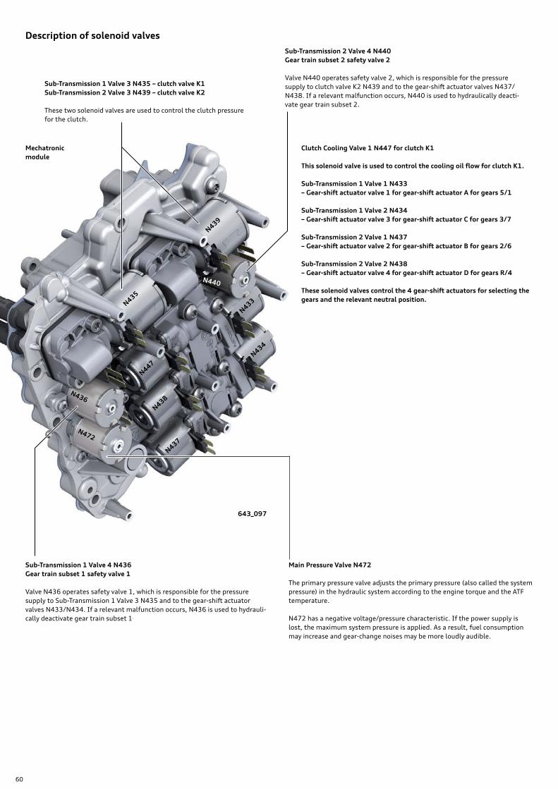
60
Description of solenoid valves
Sub-Transmission 2 Valve 4 N440Gear train subset 2 safety valve 2
Valve N440 operates safety valve 2, which is responsible for the pressure supply to clutch valve K2 N439 and to the gear-shift actuator valves N437/N438. If a relevant malfunction occurs, N440 is used to hydraulically deacti-vate gear train subset 2.
Sub-Transmission 1 Valve 3 N435 – clutch valve K1Sub-Transmission 2 Valve 3 N439 – clutch valve K2
These two solenoid valves are used to control the clutch pressure for the clutch.
643_097
Main Pressure Valve N472
The primary pressure valve adjusts the primary pressure (also called the system pressure) in the hydraulic system according to the engine torque and the ATF temperature.
N472 has a negative voltage/pressure characteristic. If the power supply is lost, the maximum system pressure is applied. As a result, fuel consumption may increase and gear-change noises may be more loudly audible.
Sub-Transmission 1 Valve 4 N436Gear train subset 1 safety valve 1
Valve N436 operates safety valve 1, which is responsible for the pressure supply to Sub-Transmission 1 Valve 3 N435 and to the gear-shift actuator valves N433/N434. If a relevant malfunction occurs, N436 is used to hydrauli-cally deactivate gear train subset 1.
Clutch Cooling Valve 1 N447 for clutch K1
This solenoid valve is used to control the cooling oil flow for clutch K1.
Sub-Transmission 1 Valve 1 N433– Gear-shift actuator valve 1 for gear-shift actuator A for gears 5/1
Sub-Transmission 1 Valve 2 N434– Gear-shift actuator valve 3 for gear-shift actuator C for gears 3/7
Sub-Transmission 2 Valve 1 N437– Gear-shift actuator valve 2 for gear-shift actuator B for gears 2/6
Sub-Transmission 2 Valve 2 N438– Gear-shift actuator valve 4 for gear-shift actuator D for gears R/4
These solenoid valves control the 4 gear-shift actuators for selecting the gears and the relevant neutral position.
Mechatronic module
N439
N435
N436
N472
N447
N438
N437
N434
N433
N440

61
643_099
643_098
Clutch Cooling Valve 2 N448 for clutch K2
This solenoid valve is used to control the cooling oil flow for clutch K2).
Basic information on the clutch cooling system for clutch K2 can be found on page 26.
Parking Lock Solenoid Valve 2 N574
This solenoid valve is also called the parking lock disengagement valve or PAV. It is used for disengaging the parking lock.
The operation of N574 is explained beginninag at page 40.
Auxiliary hydraulic module1)
Parking lock module1)
1) The auxiliary hydraulic module and the parking lock module are controlled by Automatic Transmission Control Module 2 J1006. See schematic diagram on page 72.
Parking Lock Solenoid N486
N486 is an electromagnetic in function and acts as redundant backup for holding the P-OFF function when the vehicle is moving and when transmission setting N is selected.
The operation of N486 is explained on pages 37 and 40.
Parking Lock Solenoid Valve N573
This solenoid valve is also called the parking lock engagement valve or PEV. As the name suggests, it is used for engaging the parking lock.
The method of operation of N573 is explained beginning at page 38.

62
Auxiliary hydraulic module
643_075
643_076
Electrical connector for Clutch Temperature Sensor 2 G659
Electrical connector T16b Connection to Transmission Control Module 2 J1006
ATF pump Self-holding valve SHV
Parking Lock Solenoid Valve 2 N574Parking lock disengagement valve PAV
Oil pipe Connection to clutch cooling circuitClutch K2
Clutch Cooling Valve 2 N448Clutch K2
Oil pipe connections to parking lock module
Oil pipe connections to and from Mechatronic module
The auxiliary hydraulic module is responsible for hydraulic control of clutch cooling (K2), partial hydraulic control of the parking lock, and serves as an interface for the Clutch Tem-perature Sensor 2 G659.
Electrical operation of the auxiliary hydraulic module is per-formed by Transmission Control Module 2 J1006. Refer to page 72.
The auxiliary hydraulic module has the following functional components:
› The ATF pump. › Clutch Cooling Valve 2 N448 for clutch K2. › Parking Lock Solenoid Valve 2 N574 for disengaging the
parking lock. › A hydraulic self-holding valve (SHV) for controlling the
parking lock piston. › The contact and connection module.
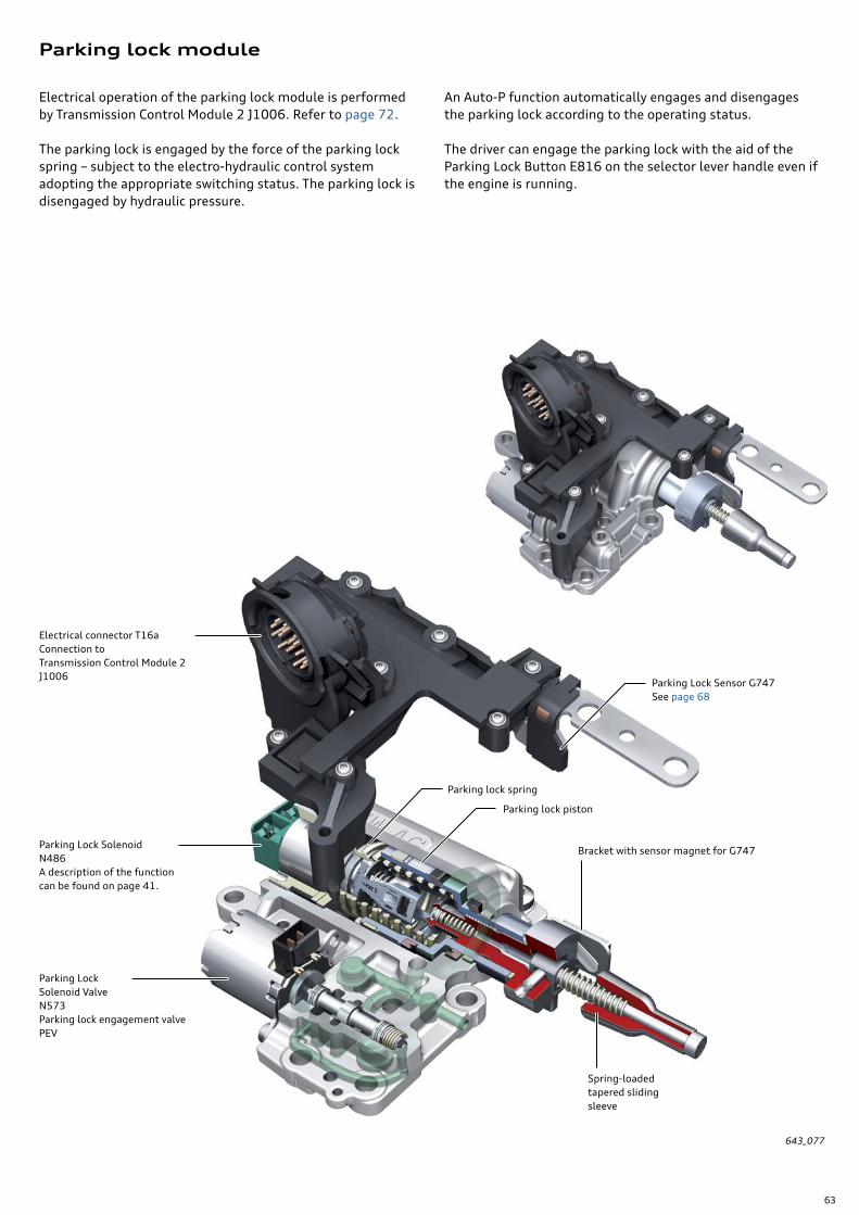
63
Parking lock module
An Auto-P function automatically engages and disengages the parking lock according to the operating status.
The driver can engage the parking lock with the aid of the Parking Lock Button E816 on the selector lever handle even if the engine is running.
643_077
Electrical connector T16a Connection to Transmission Control Module 2 J1006
Parking Lock SolenoidN486A description of the function can be found on page 41.
Parking lock spring
Parking lock piston
Bracket with sensor magnet for G747
Spring-loaded tapered sliding sleeve
Parking Lock Solenoid ValveN573Parking lock engagement valve PEV
Parking Lock Sensor G747See page 68
Electrical operation of the parking lock module is performed by Transmission Control Module 2 J1006. Refer to page 72.
The parking lock is engaged by the force of the parking lock spring – subject to the electro-hydraulic control system adopting the appropriate switching status. The parking lock is disengaged by hydraulic pressure.

64
Electronic module
643_071
643_070
Gear Position Distance Sensor 4 G490– for gear-shift actuator D for gears R/4
Gear Position Distance Sensor 1 G487– for gear-shift actuator A – gears 5/1
Transmission Input Speed Sensor 1 G632Speed sensor for input shaft 1
Transmission Input Speed Sensor 2 G612Speed sensor for input shaft 2
Transmission Control Module J217
Transmission Fluid Temperature Sensor G93
Gear Position Distance Sensor 3 G489– for gear-shift actuator C – gears 3/7
Gear Position Distance Sensor 2 G488– for gear-shift actuator B – gears 2/6
Electrical connector for Transmission Input Speed Sensor G182 and Clutch Temperature Sensor 1 G658
Electrical connector T16c for vehicle and transmission peripherals
Hydraulic Pressure Sensor 2 G546Clutch pressure K2
Hydraulic Pressure Sensor 1 G545Clutch pressure K1
Gearbox Control Unit 1 (also referenced as J743)
Electrical connector for printed circuit board
The electronic module combines Gearbox Control Unit 1 J743 and the majority of the sensors in an integrated unit.

65
Transmission control modules
Transmission Control Module 2 – J1006Address Word C2
J1006 is known as a “smart actuator” control module and controls the actuators assigned to it in response to com-mands from Gearbox Control Unit 1 J743. It also acts as an intelligent interface for several sensors and input signals. Refer to the chart on page 66.
J1006 has the following functions:
› Controlling the clutch cooling for clutch K2 (N448)
› Controlling the electro-hydraulically operated parking lock (N486, N573, N574).
› Processing the signals from the parking lock sensor G747.
› Processing the signals from Clutch Temperature Sensor 2 (clutch K2).
› Processing the signals from the steering wheel tiptronic controls.
643_072
643_003
Installation location in engine bay on left-hand side
Installation location for J1006
Dual-Clutch Transmission Mechatronic J743
Gearbox Control Unit 1 J743
There are two modules for controlling the OBZ transmission. › Gearbox Control Unit 1 J743. › Transmission Control Module 2 J1006.
Dual-Clutch Transmission Mechatronic J743Address Word 02
The designation J743 can refer to either the complete Mechatronic module or only to the Gearbox Control Unit 1 in the electronic module of the Mechatronic module. Gearbox Control Unit 1 is the master control module for Transmission Control Module 2 J1006.
The two modules along with Selector Lever Sensor System Control Module J587 communicate via the Drivetrain CAN. The schematic on page 72 provides an overall view of which sensors and actuators are read/controlled by which module.

66
Sensors and information
Speed sensors and speed data
Speed signals are among the most important items of infor-mation that a dual clutch transmission requires. The 0BZ processes the following speed data:
› Gearbox input speed.1)
› Input speed for gear train subset 1.1)
› Input speed for gear train subset 2.1)
› Gearbox output speed.2)
› Engine speed.2)
Transmission Input Speed Sensor 1 G632 Speed sensor for input shaft 1
Transmission Input Speed Sensor 2 G612 Speed sensor for input shaft 2
These two speed sensors are used to register the clutch output speeds (G632 = clutch K1 and G612 = clutch K2). Together with the signal from G182, they allow the clutch slip to be precisely calculated.
The signals from sensors G632 and G612 are used...
› For microslip control. › For adapting the clutches. › For determining the synchromesh speed for gear shifts. › For calculating the gearbox output speed.
If one of the sensors fails, the affected gear train subset is deactivated. Gearbox Control Unit 1 J743 then switches to an appropriate safe mode.
Transmission Input Speed Sensor G182
G182 is used to detect the clutch input speed in real time. The clutch housing, which is attached on one side to the dog clutch and on the other to the inner plate carrier, acts as the reluctor ring. See page 24, Figure 643_040.
The signal from G182 is used ...
› For more precise control of the clutches.
› For adapting the clutches.
› For microslip control.
If G182 fails, the speed data from the Engine Speed Sensor G28 is used as a substitute signal2).
Microslip control and certain adaptations cannot be carried out. The casing of G182 also houses Clutch Temperature Sensor 1 G658. See page 69.
1) This speed data is collected by the gearbox sensors and processed by Gearbox Control Unit 1 J743.
2) This speed data is provided by other control modules via CAN data communi-cation and processed or calculated by Gearbox Control Unit 1 J743.
Gearbox unit 1Gearbox unit 2
G632
Plug for engine speed sensor socket
Reluctor ring for input shaft 1
Reluctor ring for input shaft 2
G612

67
643_073
643_074
InformationThe sensors G182/G658 and G659 are identical in design. The speed sensor in G659 is not used.
Transmission output speed – vehicle road speed – direction of travel
Gearbox Control Unit 1 calculates the output speed and the direction of travel on the basis of the speed signals from G632/G612 and the currently selected gear. The output speed provides the basis for calculating the vehicle road speed.
To check the plausibility of the signals from the two sensors G632/G612, the wheel speed data from the ESC control module is referred to.
That information is required for the following functions:
› For gear selection and determining the gear-shift points. › For detecting the direction of travel for plausibility-check-
ing the gear selection (for example, when backing up, 1st gear engagement is barred).
› For the creep control function3).
Clutch Temperature Sensor 2 J659
Transmission Input Speed Sensor G182Clutch Temperature Sensor 1 G658
Engine Speed SensorG28
Electrical connector for G659 on auxiliary hydraulic module
Transmission Input Speed Sensor G182Clutch Temperature Sensor 1 G658
Clutch Temperature Sensor 2 G659
Electrical connector for G659 on auxiliary hydraulic module
Clutch housing

68
Travel and position sensors
Gear Position Distance Sensor 1 G487Gear Position Distance Sensor 2 G488Gear Position Distance Sensor 3 G489Gear Position Distance Sensor 4 G490
Precise detection of the movement and positions of the gear-shift actuators/selector forks is of fundamental importance for changing gear and transmission control. It is imperative to ensure that no prohibited gear-shift positions can occur. The information is read by Gearbox Control Unit 1 J743 with the aid of 4 travel sensors. Sensor magnets (permanent magnets) are used as position markers and are attached to each of the gear shift actuators. See also sensor readings on page 31.
The following gear-shift actuators (selector forks)/gears and readings are assigned to the 4 travel sensors:
› G487 – for gear-shift actuator A – gears 5/1 – sensor reading IDE02864 › G488 – for gear-shift actuator B – gears 2/6 – sensor reading IDE02872 › G489 – for gear-shift actuator C – gears 3/7 – sensor reading IDE02880 › G490 – for gear-shift actuator D – gears R/4 – sensor reading IDE02888
If one of the travel sensors fails, the gear train subset concerned is deactivated and an appropriate safe mode program activated.
In order to guarantee the required position detection accuracy, the travel sensors and/or the selector forks have to be calibrated by means of a Basic Setting. (For example, after replacing the Mechatronic module).
Parking Lock Sensor G747
G747 is used to determine the following positions(indicated in Measuring value IDE08465 for parking lock actual status):
Engaged → Intermediate position → Not engaged
Due to tolerances when determining the parking lock posi-tion, the intermediate position is indicated when the parking lock is being held in the P-OFF position by the Parking Lock Solenoid N486 (see page 37). In normal vehicle operation – P engaged or P not engaged (P hydraulically disengaged) – the intermediate position is not allowed and is registered as a DTC after a defined period.
G747 has the following functions:
› Monitoring correct operation of the parking lock.
› Providing clearance to start in P (the sensor signal is con-verted directly to the P/N signal by the Gearbox Control Unit 1).
› Generating the indications on the instrument cluster when the parking lock is not engaged (for example, risk of rolling and prompting engagement of parking lock/parking brake).
643_077
G747
Interface module
Sensor magnet
Parking lock module
The position of the parking lock is monitored by Transmission Control Module 2 J1006 with the aid of Parking Lock Sensor G747 and then communicated to Gearbox Control Unit 1 J743. G747 is part of the interface module of the parking lock module.

69
643_074
643_100
Temperature sensors
Clutch Temperature Sensor 1 G658Clutch Temperature Sensor 2 G659
The sensors G658/G659 detect the temperature of the cooling oil thrown out from the dual clutch by centrifugal force (centrifugal oil temperature). From that, the clutch temperature can be deduced and the cooling oil volume controlled according to demand. In addition, warning mes-sages and diagnostics entries are generated from the cen-trifugal oil temperature. Refer to page 26.
The sensors G658/G659 are 2 identical combination sensors each of which also houses a speed sensor and a temperature sensor within the same housing.
Sensor G658 detects the centrifugal oil temperature of clutch K1. In the case of G658, the speed sensor G182 is also used for detecting the transmission input speed1). G658 is con-nected to the electronic module of the Mechatronic module. Gearbox Control Unit 1 J743 processes the sensor reading and operates Clutch Cooling Valve 1 N447 accordingly.
Sensor G659 detects the centrifugal oil temperature of clutch K2. G659 is connected to the auxiliary hydraulic module, which in turn is connected to Transmission Control Module 2 J1006. The sensor reading is analyzed and passed on to Gearbox Control Unit 1 J743 as a temperature reading. J743 then sends J1006 the control variable for operating Clutch Cooling Valve 2 N448. See schematic diagram on page 72. The speed sensor in G659 is not used.
G658/G182
Electrical connector for auxil-iary hydraulic module
G659
Sensor magnet
G488
G489
G487
G490

70
High temperatures have a detrimental effect on the useful life and performance of electronic components.Because the electronic control module is integrated in the gearbox (immersed in oil), monitoring of the module tem-perature and, therefore, of the gearbox oil temperature is very important.
G93 is located on the circuit board of Gearbox Control Unit 1 J743. Gearbox Control Unit 1 is mounted on an alu-minium plate that serves as a heat sink for the electronic module. Pressure sensors G545 and G546 are also located on this heat sink. The aluminium plate is directly attached to the electro-hydraulic control module and is in contact with a constant flow of cooling oil through an oil channel. Therefore, the temperature of the aluminium plate closely approximates to the gearbox oil temperature.
Transmission Fluid Temperature Sensor G93 Temperature sensors in the control module
643_101
The gearbox oil temperature and the temperature of the gearbox electronic module are important items of informa-tion for the following applications:
› Temperature monitoring for initiating safety functions › Criterion for various adaptations › Adaptation of gear-shift pressure › Criterion for the warm-up program
Due to demanding requirements regarding component pro-tection, there is another temperature sensor for monitoring the electronic module temperature which is integrated in the middle of the electronic components and detects the tem-perature directly at the electronic components. That sensor does not have a diagnostics designation of its own.
The readings of the two temperature sensors are constantly checked against one another for plausibility. If there is a fault on one of the two temperature sensors, a substitute reading is generated from the readings of the intact sensor and a substitute program activated. See temperature monitoring/safety functions.
Temperature monitoring/safety functions
When temperatures at G93 of approximately 288 °F (139 °C) are detected, Gearbox Control Unit 1 J743 instigates an engine torque reduction.
A warning message (“Gearbox too hot. Please adjust driving style”) is also displayed in the instrument cluster. At DTC is registered in the fault memory.
643_071
Electro-hydraulic control module
Cooling oil channel for Gearbox Control Unit 1 J743
G546
G545
G93
Aluminium plate
Electronic module
J743
The engine torque is reduced so that it is about 70 Nm when the oil temperature is approximately 293 °F (145 °C). This improves the cooling capacity and prevents overheating.

71
Pressure sensors
Hydraulic Pressure Sensor 1 G545 Hydraulic Pressure Sensor 2 G546
G545 detects the clutch pressure of clutch K1 (actual clutch pressure).
G546 detects the clutch pressure of clutch K2 (actual clutch pressure).
The sensors G545 and G546 are used to monitor the clutch pressure of the respective clutch in each case and for calibrat-ing clutch pressure control and the primary pressure.
The actual clutch pressure is constantly compared with the specified clutch pressure calculated by Gearbox Control Unit 1 J743 and checked for plausibility. In the event of discrepan-cies (malfunctions), safety deactivation of the gear train subset concerned is initiated and the relevant safe mode program activated.
The two sensors are part of the electronic module, which in turn forms a single unit with the Mechatronic module – which again can only be replaced as a complete unit if required.
Other information
You can find information on the following topics in the Owner's Manual for the vehicle:
› Transmission faults, fault indications and messages.
› Tow-starting/towing.

72
The control modules are listed on the vehicle diagnostic tester under the following Address Words:
› J743 – Dual-Clutch Transmission Mechatronic. › 02
› J1006 – Transmission Control Module 2. › C2
› J587 – Selector Lever Sensor System Control Module. › 81
Function diagram
Wiring colors and symbols:
Mechatronic module
Selector mechanism
Powertrain CAN
To make the descriptions easier to follow, the following designations are used for the two transmission control modules:
› Gearbox Control Unit 1 J743.
› Transmission Control Module 2 J1006.
Ground cable Positive cable Transmitted signal Received signal Inside the 0BZ transmission
Twisted wires

73
Key:
E313 Selector Lever
E681 Parking Lock Indicator Lamp
E816 Parking Lock Button
G93 Transmission Fluid Temperature Sensor
G182 Transmission Input Speed Sensor
G487 Gear Position Distance Sensor 1/gear-shift actuator A
G488 Gear Position Distance Sensor 2/gear-shift actuator B
G489 Gear Position Distance Sensor 3/gear-shift actuator C
G490 Gear Position Distance Sensor 4/gear-shift actuator D
G545 Hydraulic Pressure Sensor 1
G546 Hydraulic Pressure Sensor 2
G612 Transmission Input Speed Sensor 2
G632 Transmission Input Speed Sensor 1
G658 Clutch Temperature Sensor 1
G659 Clutch Temperature Sensor 2
G727 Selector Lever Position Sensor
G747 Parking Lock Sensor
G868 Transverse Selector Lever Lock Sensor
J587 Selector Lever Sensor System Control Module
J743 Dual-Clutch Transmission Mechatronic
Electrical connectors on Transmission Control Module 2 J1006
Connector A pins 1-80 (T81a on ELSA wiring diagram)Connector B pins 81-121 (T40a on ELSA wiring diagram)
Auxiliary hydraulic module Parking lock module
643_090
Stee
ring
whe
el
tipt
roni
c co
ntro
ls
J1006 Transmission Control Module 2 J1006
K320 Parking Lock Indicator Lamp
N110 Parking Lock Indicator Lamp
N433 Sub-Transmission 1 Valve 1 – Gear-shift actuator valve 1 for gear-shift actuator A/gears 5/1
N434 Sub-Transmission 1 Valve 2 – Gear-shift actuator valve 3 for gear-shift actuator C/gears 3/7
N435 Sub-Transmission 1 Valve 3 – clutch valve K1
N436 Sub-Transmission 1 Valve 4 – gear train subset 1 safety valve
N437 Sub-Transmission 2 Valve 1 – Gear-shift actuator valve 2 for gear-shift actuator B/gears 2/6
N438 Sub-Transmission 2 Valve 2 – Gear-shift actuator valve 4 for gear-shift actuator D/gears R/4
N439 Sub-Transmission 2 Valve 3 – clutch valve K2
N440 Sub-Transmission 2 Valve 4 – gear train subset 2 safety valve
N447 Clutch Cooling Valve 1 – clutch K1
N448 Clutch Cooling Valve 2 – clutch K2
N472 Main Pressure Valve
N486 Parking Lock Solenoid – holding solenoid for parking lock OFF
N573 Parking Lock Solenoid Valve – Parking lock engagement valve/PEV
N574 Parking Lock Solenoid Valve 2 – Parking lock disengagement valve/PAV
V577 Transverse Selector Lever Lock Motor
Y5 Selector Lever Transmission Range Display

74
Hydraulic circuit diagram
Key:
AW Input shaft
BP Bypass valve
CPU Central processing unit – Outlet point on cooling channel for control unit
DBV Pressure limiting valve
DF Pressure filter
DROP Lubrication point
GS Gear-shift actuator
GSV Gear-shift actuator value
HD Primary pressure valve
HP Hydraulic pump
K Clutch
KK Clutch cooling
KUV Cooling oil valve
KV Clutch valve
NH Normally high1)
NL Normally low1)
PAV Parking lock disengagement valve
PEV Parking lock engagement valve
PHM Parking lock holding solenoid
RD Residual pressure valve
SF Intake filter
SHV Self-holding valve
SV Safety valve
TR Temperature regulator (thermostat)
TW Output shaft
VOL Volumetric flow valve
WTK Heat exchanger – fluid: coolant
WTL Heat exchanger – fluid: air
WV Change-over valve
Parking lock module
Auxiliary hydraulic module
1) Explanation of NL and NH
NL characteristic NH characteristic
NL – Normally low means that the solenoid valve has a positive current/pressure charac-teristic. That, in turn, means that as the control current I increases, so does the control pressure P.
Valve de-energized = no control pressure (0 mA = 0 bar)
If one of these valves fails, the corresponding hydraulic valve or actuator is not operated and the associated functions fail.
NH – Normally high means that the sole-noid valve has a negative characteristic. That, in turn, means that as the control current I increases, the control pressure P decreases.
Valve de-energized = maximum control pressure
If one of these valves fails, the correspond-ing hydraulic valve or actuator is set to its maximum level, for example, maximum cooling oil flow rate or primary pressure.
P
I
P
I
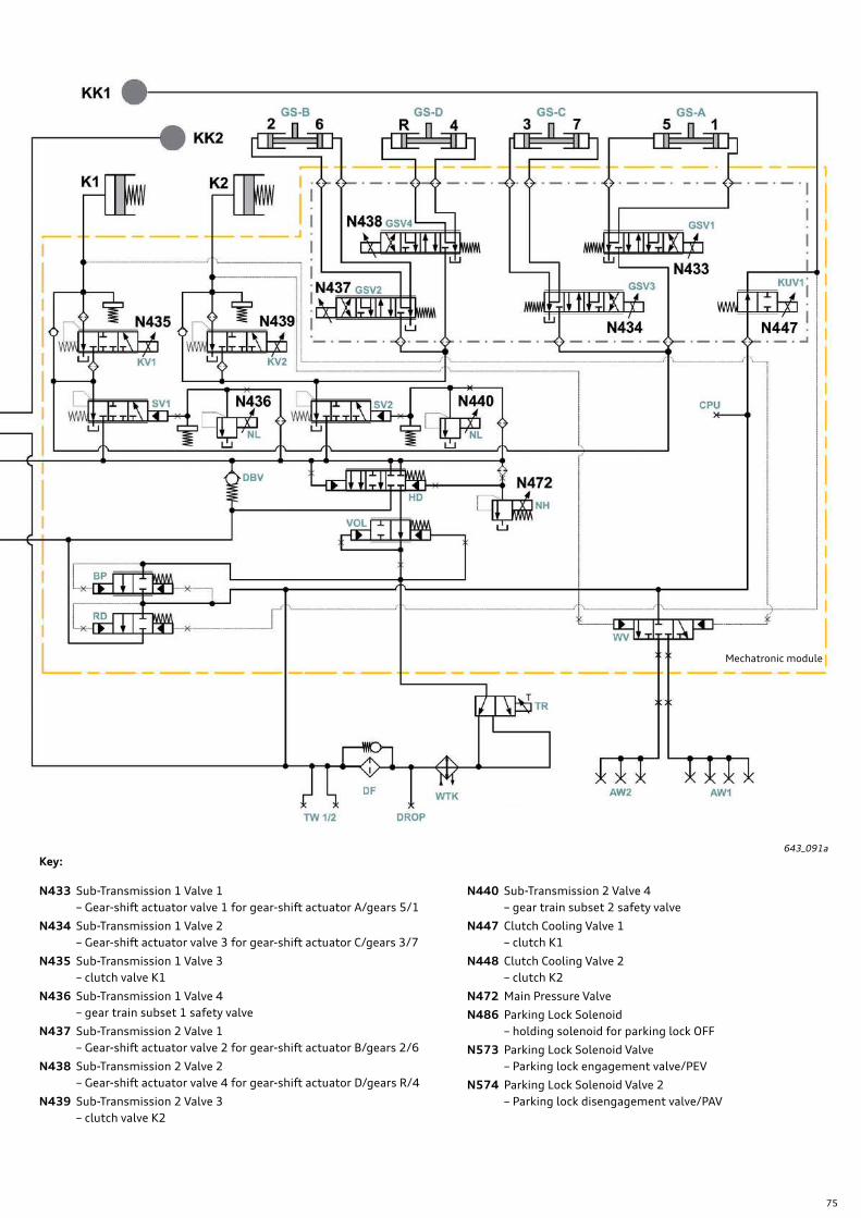
75
643_091a
N433 Sub-Transmission 1 Valve 1 – Gear-shift actuator valve 1 for gear-shift actuator A/gears 5/1
N434 Sub-Transmission 1 Valve 2 – Gear-shift actuator valve 3 for gear-shift actuator C/gears 3/7
N435 Sub-Transmission 1 Valve 3 – clutch valve K1
N436 Sub-Transmission 1 Valve 4 – gear train subset 1 safety valve
N437 Sub-Transmission 2 Valve 1 – Gear-shift actuator valve 2 for gear-shift actuator B/gears 2/6
N438 Sub-Transmission 2 Valve 2 – Gear-shift actuator valve 4 for gear-shift actuator D/gears R/4
N439 Sub-Transmission 2 Valve 3 – clutch valve K2
N440 Sub-Transmission 2 Valve 4 – gear train subset 2 safety valve
N447 Clutch Cooling Valve 1 – clutch K1
N448 Clutch Cooling Valve 2 – clutch K2
N472 Main Pressure Valve
N486 Parking Lock Solenoid – holding solenoid for parking lock OFF
N573 Parking Lock Solenoid Valve – Parking lock engagement valve/PEV
N574 Parking Lock Solenoid Valve 2 – Parking lock disengagement valve/PAV
Mechatronic module
Key:
76
From the accessaudi.com Homepage:
› Click on the “App Links”
› Click on the “Academy site CRC”
Click on the Course Catalog Search and select “950173 - The OBZ 7-speed Dual Clutch S tronic Transmission in the 2017 R8”
Please submit any questions or inquiries via the Academy CRC Online Support Form
which is located under the “Support” tab or the “Contact Us” tab of the Academy CRC.
Thank you for reading this eSelf-Study Program and taking the assessment.
The Knowledge Assessment is required for Certification credit.
You can find this Knowledge Assessment at: www.accessaudi.com
An On-Line Knowledge Assessment (exam) is Available for this eSelf-Study Program.
Knowledge assessment

95
01
73
All rights reserved.
Technical specifications subject to
change without notice.
Audi of America, LLC
2200 Ferdinand Porsche Drive
Herndon, VA 20171