Services Wind Energy 3800 ab amersfoort Developing Countries
51
PRELIMINARY OF USING AN INJECTOR FOR SUPPLYING AIR TO THE A IR CHAMBER OF A DEEPWELL PUMP J.C. VINK February 1989 Coaches: Ir. P.T. Smulders Ir. J.W. Cleijne Ing. J.F.L. Diepens WIND ENERCY CROUP Technical University Eindhoven Faculty of Physics R 978 S Laboratory of Fluid Dynamics and Heat Transfer P.O. Box 513 5600 MB Eindhoven. the Netherlands Services Wind Energy Developing Countries p.O. box8S 3800 ab amersfoort holland
Transcript of Services Wind Energy 3800 ab amersfoort Developing Countries

PRELIMINARY INVESTICATI~S OF USING AN INJECTOR FOR SUPPLYING AIR TO
THE A IR CHAMBER OF A DEEPWELL PUMP
J.C. VINK
February 1989
Coaches: Ir. P.T. Smulders Ir. J.W. Cleijne Ing. J.F.L. Diepens
WIND ENERCY CROUP Technical University Eindhoven Faculty of Physics
R 978 S
Laboratory of Fluid Dynamics and Heat Transfer P.O. Box 513 5600 MB Eindhoven. the Netherlands
Consu~ancy Services Wind Energy Developing Countries
p.O. box8S
3800 ab amersfoort
holland

CONTENTS
Acknowledgements
Summary
Chapter 1. Introduction 1.1. Background 1.2. Criteria for the injector 1.3. Possibilities 1.4. Introduction
Chapter 2. Theory 2.1. Calculations 2.2. Other quantities 2.3. Calculations of dimensions
Chapter 3. Experimental set-up 3.1. General set-up 3.2. Measuring equipment 3.3. Measuring procedures
Chapter 4. Results and discussion 4.1. The relation between PvO and P3 4.2. The relation between Qw and Pvo 4.3. The relation between Qa and Qw 4.4. The relation between Qa and P3
Page
3
4
5 5 6 7 7
9 9
11 12
14 14 15 15
17 17 20 22 24
Chapter 5. Conclusions and recommendations 26 5.1. The feasibility of the injector-concept 26 5.2. Recommendations for further research 27
List of references 31
List of symbols and subscripts 32
Appendix 1. Experimental results 33
Appendix 2. Calculations of the nozzle-diameter 43
Appendix 3. Calculations on the injector-model 45
2

ACKNOWLEDGEMENTS
Working on this first traineeship roused my interest in the area of fluid dynamics, as well in the so far unknown world of setting up one's own research-program and trying to carry it out succesfully.
Of course I would be a terrible liar if I said I did all the work by myself. Many persons helped me in times of practical, theoretical or psychological trouble and if I mentioned all of them the list would never be complete. However there are four persons whom I'd like to thank in particular: Paul Smulders for devoting some of his precious time for my
benefit. Louis Wasser for his great help in constructing the designed
experimental set-up and delivering the necessary measuring and experimental equipment.
Jan Diepens for compensating my weakness in technical drawing and my clumsiness in handling the equipment.
Rob van Noort for lending his computer to write the report and especially for recovering the files I deleted accidently.
At the end of the report some recommendations for further research are proposed. I would be happy to assist anyone who is going to do this inquiry. One can contact me via the CWDadministration or via the administration of the Eindhoven Technical University.
3

SUMMARY
The traineeship discussed in this report dealt with the problem of air-shortage in the delivery-airchambers in deepwell pumps. One of the solutions for this problem is using an injector. This is a device in which a high-speed "motive fluid" (in this case water that was drawn off the pump itself) mixes with a low-speed "secondary fluid" (in this case the needed air). The mixture then is injected back into the pump, consequently eliminating the air-shortage. The mixture must have a higher pressure than the normal air pressure, for the pressure in the deepwell pump (which is positioned well below the groundwater level) is also higher than the air pressure. The used water flow cannot be too great, to prevent inefficiency of the water pump. These demands were translated into boundary conditions for the problem. An examination of the various possibilities of thi& injector-concept, as well of its feasibility for practical use, has been made.
First the problem was treated in a theoretical way, using some basic principles of fluid dynamics and some particular theories found in the literature. Special attention was payed to calculations of the pressure of the mixture .flowing out: of t:.he. injector, the water flow that was necessary and tEe air flow that could be reached. An experimental set-up was designed and constructed to test the relations. The measurements were done under steady flow-conditions and therefore the results cannot be applied to the practical (unsteady) situation. Some variables, such as the diameters of the injector and the incoming water pressure, were changed during the experiments.
The results were summarized in four graphs (page 17, 19, 21 and 24). Reckoning with the water pressure at the inlet of the injector (which directly depends on the static height) and the permitted water flow '(which depends on the leak acceptable in the pump), it can be concluded that it is possible to construct an injector with an acceptable air flow and a reasonable pressure of the ourflowing mixture. Thus it can be concluded, as far as the steady conditions allow such a conclusion, that the injector-concept is feasible for practical use.
However, more research has to be done. Especially the measurements under unsteady flow-conditions need to be examined thoroughly. When this is done, a procedure can be designed, with which it is easy to see what kind of injector is needed for a particular pump.
4

Chapter 1. INTRODUCTION
1.1. Background
For a long time people have been using wind-energy, especially for water pumping purposes. The past two decennia there has been a lot of research on windenergy, concentrated on the use in the Third World Countries. The Consultancy Services Wind Energy Developing Countries (CWO) in the Netherlands has designed and developed some different types of windmill-driven water pumps. More about these mills and their applications one can find in the literature (1).
Appliances for developing countries require other conditions then those usual in the Western World. For example, as a result of the shortage of well-trained engineering personnel in the Third World, the appliances must be relatively simple, with little maintenance needed. Of course things cannot be made too expensive. The waterpumping section of a CWO-windmill is equipped with a pistonpump (2). To reduce the impedance of such a system one can insert an airchamber (figure 1). When the waterpumping section is placed beneath the local groundwater level ("deepwell pump") a delivery-airchamber (figure 1) is used. But the pressure of the enclosed air will always be higher than the normal air pressure and the air will therefore dissolve slowly into the water, resulting in an increased impedance of the system, due to loss of air in the airchamber. This problem was the subject of my first traineeship. CWO asked me to find a way to bring fresh air into the delivery-airchamber. Already a temporary solution was found by attaching a dripping device above ground-level and leading the waterdrops, with enclosed air inbetween, all the way down to the water pump (which sometimes can be a distance of over 40 meters). This solution was not satisfactory, for the thin watertube was very easily obstructed by dirt or algae, especially under tropical circumstances.
Figure 1. Scheme of a windmill-driven deepwellpump with airchambers.
l)e:l..t~-A1RCt'\AM~ .......... ----<:::__ __ ,...,c.--_,
PUMPRoO ----ir--+--IIl1A " ~"1'Ct.J VAi,. \Ie-
._---
5
~1tou."'OWt\T~-VE"L
De-efWe't.L -rrtlfil--........ PuMP
R.AwOOW.vt\eiGtt'TJ tip
L-., $(AC Tta..t -IAIRCt-IAMt!£A.
'---- ~I..E"T

Another solution could be to use a water-driven air-injector and it is this particular device that has been investigated. In figure 2 a scheme of an injector is drawn. The motive fluid (in this case water) enters the secondary fluid (air) with high speed and there is intense mixing. The waterjet slows down and therefore energy can be used to increase the pressure of the air. The water-air-mixture coming out of the injector must somewhere enter in the water pump and must have a higher pressure than the outside air pressure. The advantage of an injector is that it matches with demands put forward earlier: it is cheap, easy to make and to keep up, because of the absence of moving parts.
Figure 2. Scheme of an injector.
1.2. criteria for the injector
.----- It.,) LET
!i::riIt:"H+-- t/lOTIV(; FLUID
",*-- sr:cotvOA(~ r\..UlO
Before proceeding to theory and experiment, an investigation on some design-conditions is required. a). A delivery-airchamber (contents about 10 1itres) in a
deepwell pump will dissolve totally in about one week time, so a refreshing rate of 60 c1. air per hour is necessary. This is very difficult to realise (for comparison: a human being breathes about 10 litres of air every minute), so the criterium was set on refilling the airchamber completely every hour. An advantage of air in water is that it makes water more elastic and can reduce the occurence of sudden, great forces within the pump-system.
b). The high-pressure water of the pump is used for the injector; inherently this means a reduction of the pump efficiency. A maximum of about 5% of the totally pumped volume is allowed to be used by the injector. with the known capacities of the CWD-2740 and the CWD-5000 windmills (3) calculations learn that a water flow of 40-130 litres per hour is available.
6

c). The injector must be large enough to prevent obstruction by dirt or algae. As the smallest acceptable diameter (the nozzle, figure 2) 1 mm has been chosen as a preliminary criterium. This may have to be adjusted later.
1.3. Possibilities
The place where water is drawn off (the inlet to the injector) and the place where the mixture flows back into the system (the outlet) are not fixed. Naturally the water pressure at the inlet must be higher than at the outlet. Figure 3 gives an idea of the pressures in the pump. In figure 4 the possibilities for inlet and outlet and the possible combinations are drawn. Inflow of the water-air-mixture below the footvalve is not recommended, so only four combinations are left to choose from. The best choice is combination 1, because it is practically realizable; by adjusting the outlet the effective working-time of the injector can be varied, for when the piston moves below the outlet the injector cannot work (pressures at inlet and outlet are equal). A little valve in the air conduct-pipe is needed to prevent filling up with water during that part of the stroke in which the injector does not work, and of course if the pump is standing still.
1.4. Introduction
In this report some preliminary experiments are described (chapter 3 and 4) to investigate the feasibility of the injector-system. Experiments were restricted to steady flow conditions, and therefore do not reflect the problems one might encounter owing to the inherent pressure fluctuations in a real pistonpump. Chapter 2 gives a simple adapted theoretical background based on known theories of fluid dynamics and injectors. Finally in the last chapter some recommendations are given for further research and the feasibility of the injector concept is discussed.
Figure 3. Scheme of the pressures in the pump.
1""-----..., j i
L--- __ 1
7 Hp ~----~--~--~--

.11.---__ _._' .... ~ '/
MA}(. COjv\~II\iATlO N i ~ Ai + .B 1
It..Ii'('T';'I~ (itvJrCTOR. \NORI(S \t= Pi~To/IJ LS, 1>t:llNE'f"N O\lTL~T AND MAY-
HAl<
.!JlA~\kJ '1 T+t€ Up-- STw:1.cKe).
CoH\7INAilON :2: Al -t- 52-(rt.JJe:'Tc~ WCKKS, AlL.. THc TIMe
l)Vl!lIt.J<:i T+tE LA'\>- s,nzo"e:- )
( ItJ j"E' (-rott 'N)~t I~ PiS TOrv \~ ltTW~ iPllLEi'T AND Ct4.T\E'T,
UlJI(IN<i T+1f IAP- ~'T('.o~)
C.CMf)\NAIlON '-\: AA -T &2-(~:cro~ \/\lO(.K& IF ?is Tcl'J is
WjE'C.TCP- WffN ~~\~D .,.~~T~;!Stto~e) t="\§.~C~ COH.i?\lvATIOtJS of IN- AND
Olx-rLET.
8

Chapter 2. THEORY
Figure 5 and table 1 give the definitions of symbols and subscriptions used in this report, as well the names of the various parts of the injector. For a complete list of symbols, super- and subscripts as well their dimensions I refer to the list of symbols, page 29.
o
1 CI L.1t.Jna.,C1\f. II M')(I~ Ctf~""2oEt" OR T+-'R.okr - SEC-nON 1
Figure 5. Scheme of an injector.
2.1. Calculation of the pressure
Table 1. Symbols and subscripts.
SYMBOLS: Q flow ~ density f> pressure d diameter A : cross-section area v : velocity
SUBSCRIPTS: 9 gas v : liquid m mixture n : nozzle t throat d diffuser 0,1,2,3: see figure 5
The Navier-Stokes equation of momentum and the equation of continuity, going from sections 0 to 1 and from 1 to 2 give rise to the following expressions:
VV1~VIAVI + VglrglAg1 = Vm2~2Al VvOfvoAvO + VgofgoAgo = vVIyvIAvl + Vgl~glAgl
~ t PvlAvl + PgIAgl + VV:qV1Avl + Vg19g1Agl = Pm2Al
(2.1.1)
(2.1.2)
Assuming that vgltgl « vV1~V1 (air is lighter and slower then the water), thae m2 ~ fVl = gv (quite true if little air is entrained by the ater), (2.1.1) can be rewritten as:
Vm2 = vVl.(Avl/A1) (2.1.4)
Likewise, assuming VgO~go « vvoYvo and VgI 0gl« VV1fvl' (2.1.2) can be rewriet~n as: )
9

To rewrite expression (2.1.3), we need the Bernoulli-equation, applied to the gas for sections 0 to 1:
(2.1.6)
Here it is assumed that fgO ~ Pg1 (incompressibility) and that the air flow is rotation-free. Both assumptions are not likely to be fulfilled, for air is very compressible and the flow is not entirely frictionless. For the moment, however, they will do. Substituting this Bernoulli-expression into (2.1.3), with VgO « vg1' and realizing that Av1 + Ag1 = A1 and that Pv1 = Pg1 = P1, we get:
2 2 P1A1 + vV1~V1Av1 + 2(pgo - P1)Ag1 = Pm2A1 + Vm2~m2A1
For section 2-3 again Bernoulli is applied:
P2 + ~Vi2~m2 = P3 + ~V~~3 Conservation of mass requires:
(2.1.7)
(2.1.8)
vm2ym2A1 = v3~3A3 (2.1.9)
and therefore (inserting A2 = A1 and ~m2 = y3 ~ ~v):
P2 = P3 - ~Vi2~V.(1 - (A1/A3)2) (2.1.10)
Substituting (2.1.10) in (2.1.7) yields:
2-P1A1 + VV1~vAV1 + 2(Pg~ - P1)Ag1 =
A1(P3 - ~Vm2~v.(1 - (A1/A3)2» + ~2~vA1 (2.1.11)
Using Bernoulli on the section 0-1 for the water and dividing by A1 results in:
P1 + 2(pvO - P1)·(Av1/A1) + 2(P~0 - P1)·(Ag1/Al) = P3 + "5V~2YV. (1 + (A1/A3) 2 ) (2.1.12)
Defining a := Av1/A1' p := A1/A3 and after some rearranging, using equation (2.1.4), (2.1.12) can be rewritten as:
-P1 + 2apvO + 2(1 - a)pgo = P3 + (PvO - Pl).a2 (1 + P2)
and so
P3 - PI
Pvo - P1 (2.1.13)
Simplifying by putting PI ~ PgO' the final result can be written as:
P3 - Pgo
PvO - PgO = 2a - a 2 (1 + P2)
10
(2.1.14 )

Note: because of the simplification PI ~ Pgo, nothing can be said about how much air is transported by ~he process. It is a model to estimate the relation between the pressures at the inlet and the outlet. Equation (2.1.14) holds when there is only little air entrained by the water.
2.2. Other quantities
The relationship between the pressure at the inlet (PvO) and the water flow at the nozzle (Qvl) can be calculated from the Bernoulli-equation for section 0-1 for water:
1 t 0 1 ~ PvO - PVl = ~VVl)Vl - ~vvoyvo (2.2.1)
Assume that vvO « vvl and that Pv1 = PI ~ PgO' then
vv1 = j(2(PvO - Pgo)/9v ) (2.2.2)
resulting in a water flow of
Qv1 = Av1· vVl = ~~d~.j(2(PvO - Pgo)/Yv) (2.2.3)
The relationship between the air flow Qa (= Q 1) and the water flow Qw (= Qv1) is very complicated. ~n the literature a relation for the mass flow-ratio between the motive and secondary fluid can be found (4). It can be written as:
Mg/Mv = J'«fg/9v).(I/a.).Ks.Kel.f~) (2.2.4)
M : mass flow Ks : head-loss factor because of the flow
pattern of the air. Depends on the construction of the injector. About 3.10-5 .
Kel: head-loss factor because of the expansion of the waterjet between nozzle and throat. Depends on the angle of this expansion. About 0.3.
f s : fraction of total suction that is used. If no air can enter the injector, the water flow will create a suction-pressure in the throat. When there is an air flow, only a fraction of this suction-pressure will be used: f s ' Depens on quality of the mixing between water and air. BetWeen 0.1 and 0.4.
n : the power of fs (an empirical value). Depends on fs: if fs < 0.6 then n = 0.6.
To relate these mass flows to volume flows the densities must be considered, especially the density of the air. -------------------------------------------------------------Remark In discussions on this equatIon after this report had been finalized. some doubts came up on the validity of equation (2.2.4). This question will have to looked into when the research in the injector is continued.
11
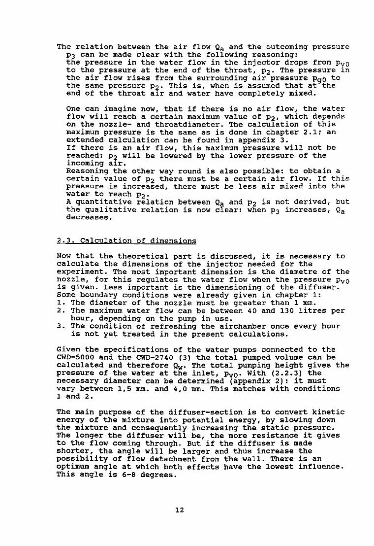
The relation between the air flow Qa and the outcoming pressure P3 can be made clear with the following reasoning: the pressure in the water flow in the injector drops from PyO to the pressure at the end of the throat, P2. The pressure 1n the air flow rises from the surrounding air pressure PgO to the same pressure P? This is, when is assumed that at the end of the throat a1r and water have completely mixed.
One can imagine now, that if there is no air flow, the water flow will reach a certain maximum value of P21 which depends on the nozzle- and throatdiameter. The calculation of this maximum pressure is the same as is done in chapter 2.1; an extended calculation can be found in appendix 3. If there is an air flow, this maximum pressure will not be ~each7d: P? will be lowered by the lower pressure of the 1ncom1ng a1r. Reasoning the other way round is also possible: to obtain a certain value of P2 there must be a certain air flow. If this pressure is increased, there must be less air mixed into the water to reach P2" A quantitative relation between Qa and P2 is not derived, but the qualitative relation is now clear: when P3 increases, Qa decreases.
2.3. Calculation of dimensions
Now that the theoretical part is discussed, it is necessary to calculate the dimensions of the injector needed for the experiment. The most important dimension is the diametre of the nozzle, for this regulates the water flow when the pressure Pvo is given. Less important is the dimensioning of the diffuser. Some boundary conditions were already given in chapter 1: 1. The diameter of the nozzle must be greater than 1 rom. 2. The maximum water flow can be between 40 and 130 litres per
hour, depending on the pump in use. 3. The condition of refreshing the airchamber once every hour
is not yet treated in the present calculations.
Given the specifications of the water pumps connected to the CWD-5000 and the CWD-2740 (3) the total pumped volume can be calculated and therefore Qw. The total pumping height gives the pressure of the water at the inlet, Pvo. With (2.2.3) the necessary diameter can be determined (appendix 2): it must vary between 1,5 rom. and 4,0 rom. This matches with conditions 1 and 2.
The main purpose of the diffuser-section is to convert kinetic energy of the mixture into potential energy, by slowing down the mixture and consequently increasing the static pressure. The longer the diffuser will be, the more resistance it gives to the flow coming through. But if the diffuser is made shorter, the angle will be larger and thus increase the possibility of flow detachment from the wall. There is an optimum angle at which both effects have the lowest influence. This angle is 6-8 degrees.
12
static pressure is needed to make it possible for the mixture to return to the pump. The Bernoulli-law and the law of massconservation lead to:
(2.3.1)
This is an expression in the case of an ideal flow. In laboratory conditions the gain of pressure will be lower than that calculated with (2.3.1).
Please note that the factor (AI/A3) 2 = (d1/d3 )4 rapidly converges to zero. If d3 = 2dl is chosen the pressure-gain will be about 94 % of the maximum gain, ~Vi2~V' If d3 = 3dl this gain is already 99 %.
Earlier the possibili~y was mentioned of regulating the effective working time of the injector by adjusting in- or outlet (1.3). This procedure would lower the water flow to the injector. But if the mean flow to the injector should be about 5 % of average pumpflow, the momentary water flow in the injector, QW can be made higher than the mean value, resulting in a bigger possible nozzle-diametre, as the high-pressure differences are cyclic. In the calculations of the diametres (appendix 2) an effective working time of liS pumpstroke has been taken into account, allowing a larger sizing of the nozzle diameter.
13

Chapter 3. Experimental set-up
3.1. General set-up
The experiments on the injector can be separated into two different types:
measurements under steady conditions. Here the water flow is kept constant to examine the general relationships between the various variables like the pressure at the inlet (Pvo) , the pressure at the outlet (P3)' the water- and air flow and the ratio between the areas of the nozzle and throat crosssections. measurements in unsteady conditions. Here the experimental set-up is connected to a test pump to simulate the practical environment. It is important to see what the influence is of positioning in- and outlet on the pump and to determine the "effective working-time". In this effective working-time the injector can be regarded as working stationary.
In figure 6 a scheme of the general set-up is drawn in the case of the stationary measurements. With the pressure-vessel the water flow Qw is kept on the constant entering pressure PvO' This pressure can be varied and is measured by the pressure transducer. The incoming air passes a flowmeter before mixing with the water. The pressure at the outlet P3 is also measured by the pressure transducer. A valve is mounted in the outlet-pipe to measure P3'
The final dimensions of the injector were (se£ Appendix .te): -dn varied between 1,0 mID. and 3,0 mID. -dt varied between 3,0 mID. and 4,0 mID. -the diffuser began with the same diameter as the throat and spread out to 11 mID., with an angle of 8,7 degrees.
-after the diffuser all tubes had a diametre of 11 mID. -the nozzle was cone-shaped and fitted in the cone-shaped injectorhouse in such a way that the distance between nozzle and injectorhouse was about 1 mID. everywhere.
Figure 6. Scheme of the experimental set-up.
14

3.2. Measuring equipment
Water flow. Qw was determined by measuring the watervolume (in a measuring glass) per time (with a countdown alarm). The reading error on the measuring glass was 3 mI. on a total volume of 500-1000 mI., therefore the relative reading error was 0,3-0,6 %. In order to raise the accuracy the measurements were done repeatedly. This gives a mean value and a standard deviation in the watervolume. If the standard deviation was smaller than the reading error, the reading error was taken as the absolute error in the volume. The error in reaction time in pressing the countdown alarm on and off was about 0,2 sec. on a total measuring time of 8-30 sec., leading to a relative error of 0,7-3,0 %.
Air flow. Qa was measured with an integrating gasflowmeter for flows of several litres per hours. The apparatus did not need to be calibrated. It was a continously measuring device, and to determine the air flow (Qa> the beginvalue as well as the endvalue of the needle on the meter had to be read, both having an error of less then 0,5 l/hr. The error will increase if the flow increases, for the needle will rotate faster and reading becomes more difficult. The errors worked with are:
Qa S 150 l/hr ~ ~Qa = ±0,5 l/hr 150 l/hr < Qa $ 300 l/hr -+ AQa = ± 1 l/hr 300 l/hr < Qa S 450 l/hr ~ AQa = ± 2 l/hr
The air flow measurements were repeated several times to increase the accuracy. If the standard-deviation was bigger than~Qa' it was taken as the absolute error in the air flow.
Pressure-transducers. Before using the transducers they were calibrated to see if the output (in volts) was linear with the input (the pressure). The calibration showed that this was indeed linear, but that every day the zero-point had to be adjusted again. The transducers worked from 0 to 10 bar overpressure and the accuracy was nearly always 0,01 bar, sometimes slightly more.
3.3. Measuring procedures
The first set of experiments involved the steady situation. The measuring procedure was: --the pressure in the pressure-vessel was adjusted to a value
of about 0,5 bar. --the topvalve as shown in figure 6 was opened and the
water flow was measured three times (five times if the flow varied heavily) in the way explained in 3.2.
--the air flow was measured three times. --the bottomvalve was slowly closed until the air flow stopped
(the water flow continued). Then the pressure-at-outlet was read off on the pressure-transducer: this was the maximumpressure that the injector could create.
--the pressure in the air-vessel was increased by about 0,5 bar and the procedure was repeated.
15

At first the experimental brass injector did not have a diffuser. Also not all the transitions (p.e. the transition between injector and the outlet-tube) were smooth and this
created extra resistance. Altogether the water flow did not run through the injector, but rather flowed back into the air-inlet. It was decided that the new injector should have a diffuser, smooth transitions and was to be made of perspex to make it possible to watch the process of mixing.
The measuring procedure described above was repeated for different diametres of the nozzle, and again for different throat-diameters. The following combinations have been investigated:
dt (rom) 3,0 3,5 4,0
dn (rom) 1,0 - 1,5 - 2,0 - 2,5 2,0 - 2,5 - 3,0 2,0 - 2,5 - 3,0
While measuring it became clear that there was a so-called "turning-point" in the whole process. If PvO was gradually increased, there was a point were the flow-pattern changed. At the same point the water flow Ow decreased suddenly. In total three kinds of flows were noticed: (1) the waterjet flowed undisturbed through throat and
diffuser. This was only the case for dn = 1,0 and 1,5 rom., and for low pressures.
(2) the waterjet ran through throat and diffuser with very high speed and only a thin waterfilm was formed on the diffuser-side. This occurred before the turning-point, for a nozzle diameter greater than or equal to 2,0 rom., and also always after the turning-point.
(3) "the foam-stream": the waterjet spread out in the throat and mixed thoroughly with the air to a foam which filled the diffuser completely. This kind of flow could also be heard by its typical fierce hissing sound. It occurred around the turning-point.
Another observation was that the injector-system seemed to have a higher resistance after the turning-point, because the total water flow decreased suddenly when the pressure was increased. Around these points some more measurements were done.
A second set of measurements was done to investigate the relation betweeen air flow and outlet-pressure P3' This is done for nearly every combination of dt and dn (except dt = 3,0 rom and dn = 1,0 and 1,5 rom), with two different pressures. The bottomvalve was slightly closed (while the injector was working) until a certain value of P3 was reached (p.e. 0,10 bar). Then the air flow was measured (three times) and P3 again increased, etc. till the air flow stopped completely.
16
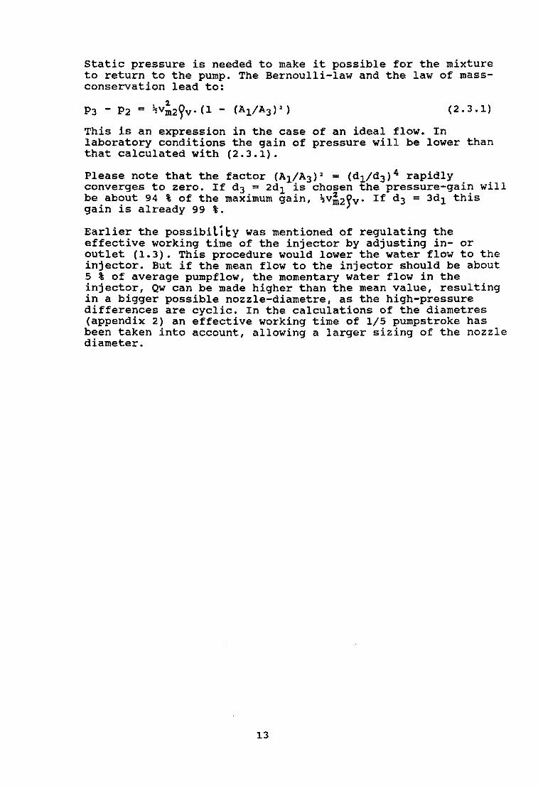
Chapter 4. Results and discussion
Only the results of measurements done on the injector with diffuser are given.
4.1. The relation between PvO and P3
In graphs LA-1C the maximum outcoming pressure P3-PgO is plotted against the incoming pressure PvO-PgO.
1
j(-~:
0-0'
1 9-'V ;
d~ 210
J.,t;; 3,0
-:.l" ~~\b.
6\ ~ 4P MVVI
.-"""""-__+----4-----f. .. ----- _.--&.-113
~~\C.
17

In chapter 2.1. it was calculated that the relation between these two parameters is given by:
P3 - PgO
PvO - PgO (2.1.14)
This relationship was derived making the following assumptions: '" PI === Pgo *Om ===9v * -lrvo « vvl * ~ gO === ~ gl and rot (Vg) =0
Table 2, List of theoreticall graphical slopes of graphs lA-Ie.
dt
3.0
3.5
4.0
p
0.074
0.10
0.13
'P. .. Oi OF 'ttl.e T~E'Oft0'ICAL. AtJD
"tt~Pt\lC..AL. i S\...of't~
N;frINST c(.. ~ Q
l
"'" V)
dn
1.0 1.5 2.0 2.5
2.0 2.5 3.0
2.0 2.5 3.0
\.0
oS
0.111 0.250 0.444 0.694
0.327 0.510 0.735
0.250 0.390 0.563
18
D o
theory
0.210 0.437 0.690 0.904
0.546 0.757 0.924
0.436 0.625 0.804
o
\l
graphs
0.155 0.285 0.488 0.394
0.372 0.365 0.425
0.251 0.273 0.349
'til o
difference
-0.055 -0.152 -0.202 -0.510
-0.174 -0.392 -0.499
-0.185 -0.352 -0.455
~~Pt-lS
0--:;;-; eli:' 3.0 W\M.
O-V: c4 = 3 S W\WI .
0-0: ct~ ~ ~.o W'M.

The slope of the graphs must have the value calculated in (2.1.14), but they can differ because of the assumptions made. Table 2 gives a listing of the theoretically calculated values and the graphically determined values. In graph 10 both the values are drawn against 0 (neglecting 13). As can be seen, the practical slope is smaller than the theoretical one. Two possible explanations are:
a). PgO F Pl' but Pgo = Pl + /l Pl' It can be calculated (appendix 3) that (2.1.14) changes into:
P3 - PgO
PvO - Pgo
L1 P1 = 20 - 0 2 (1 + p2) + ---------
Pvo - PgO (1 - 0 2 (1 + 13 2
) )
Because 0 2 (1 + 13 2 ) < 1 it can be concluded from the graphs that P1 is negative, thus that P1 > PgO' If this was true, there could be no air flow into the inJector. Thus it can be concluded that the difference between the theory and the results cannot be explained by putting PgO = P1 +Llp1'
b) • 9 m f: 9 v, but 9m = J.L9v1 with J.L < 1. It can be calculated (appendix 3) that in this case (2.1.14) can be written as:
P3 - PgO
PvO - PgO
Because J.L < 1 the slope calculated with this expression will be smaller than when calculated with (2.1.14).
Another remarkable observation that can be made from table 2 is, in the case that dt = 3.0 rom, the existence of an optimum value of 0 (about 0.5). Theoretically this optimum exists at 0
= 0.99. A possible explanation might be the fact. that, with 13 so small, the diffuser section has little influence in the flow pattern of the air-water-mixture. In this case the system could be seen as working without a diffuser. Calculations on such a system learn that the optimum value of o is about 0.5 (appendix 3).
c). As no friction losses have been included in the model. it is clear that the measured pressure ratios will be lower than the calculated one. Losses arise in the flow of air and water to the throat. wall friction losses in the throat, diffuser losses (which would be quite substantial) .
19

4.2. The relation between Ow and Pvo
In the graphs 2A-2C the water flow Qw is plotted against the square-root of the incoming pressure PvO-PgO'
I
t ~)I.:I,.o
c:>-e.i,'S /
~. V-:V:,o !
1 i.)oQ ','fi " t~
QvJ
:t II :1 i / I . ;:~ , I
! /
100
.. , c:l ll : Jfo"1(~ 2,0
0-0: J..<i>
VooV: J,o
t • •. « l
In chapter 2.2. was derived that
~1 ... Jurd~./(2(PvO - Pgo)/fv)
"~:J.o
0-0: 2,S V.:ti1: J,c
(o.4=4,OMI
°o~--~--~--~·---r~--1 Vw ...
~~~ w.;-~
(2.2.3)
With dn given in mm, Qw in liters per hour (l/hr) and PvO-Pg~ in bar, (2.2.3) can be rewritten as (inserting 'w ... 1000 kgfm ):
2-and therefore the slope of the graph should be 40dn • Table 3 gives a listing of this theoretical slope and that determined from the graphs. This latter consists of two parts, because of the turning-point which was observated during the experiments (chapter 3.3).
20

Table 3. List of theoretical/ graphical slopes of graphs 2A-2C.
dt dn theory graphs first second
3.0 1.0 40 43 30 1.5 90 74 59 2.0 160 142 124 2.5 250 217
3.5 2.0 160 148 125 2.5 250 221 3.0 360 296
4.0 2.0 160 146 128 2.5 250 221 3.0 360 291
From table 3 the following conclusions can be made: a). The first part of the graphs, i.e. before the turning
point, is fairly consistent with the theory. b). The second part of the graphs give lower slopes,
indicating an increased resistance of the system. The most important explanation is a sudden increase of Pl' This explanation is supported by the observations made during the measuring program (see chapter 3.3). When the "foam-stream" occurs it is likely to assume that the process of mixing in the throat is suddenly completely isolated from the outlet of the injector and that therefore the pressure P1 can increase. On the other hand, in a smooth and steady flow situation, there is a fairly good connection between the pressures inside and outside the mixing-chamber, preserving P1 from sudden changes.
c). The slope of the graphs is independent of the diameter of the throat, as was already stated in the theory (Qw only depends on dn and Pvo-Pgo)'
d). The turning point pressure (Ptp)' this is PvO of the turning point (chapter 3.3), increases with the nozzle diameter. Because the turning-point is a result of the m1x1ng process in the throat, one can expect Ptp to be dependent on Q, the ratio between dn and dt. But no quantitive relationship is found. Especially strange are the graphs of dn = 2.0 mm:
when dt = when dt = when dt =
Possible explanations:
3.0 mm' then Ptp ~ 4.0 bar 3.5 mm, then Ptp ~ 2.7 bar 4.0 mm' then Ptp ~ 3.4 bar
* the turning-point depends only on dn (and it occurs between 2.7 and 4.0 bar).
* the beginning of the turning-point is a process that ean start in a large "high-rise" pressurearea and it is initiated by any little disturbance.
21

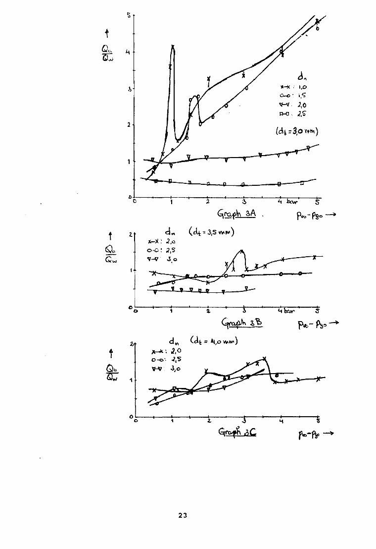
4.3. The relation between Oa and Qw
In the graphs 3A-C the ratio between the air flow Oa and the water flow Ow is plotted against the incoming pressure PvO-PgO' In chapter 2.2. an expression is stated giving the relation between the mass flows of the air and the water:
(2.2.4)
The mass flow and the volume flow are related as M = O.~. If the air is treated as incompressible -as is done in the derivations in chapter 2.1.- relation (2.2.4) simply changes into:
(2.2.4.a)
which would implicate a constant ratio Oa/Qwl for all factors are considered as a constant.
If the air is seen as a compressible gas (not unnatural) the density of the air is related to the pressure by the BoyleGayLussac-expression Pg = ~g.R.T , and (2.2.4.a) will change into (inserting the pressure just before the throat, P1):
Qa/Qw = C. (1/a).J{1/P1) (2.2.4.b)
with C = J(~v.R.T.Ks.Kel'~)'
As can be seen in (2.2.4.b), it seems to be unuseful to relate Qa/Qw to PvO-PgO' because the relation between PvO-PgO and Pl is still unknown. When dt = 3.0 mm, with dn = 2.0 or 2.5 mm and when dt = 3.5 mm, with dn = 2.5 or 3.0 mm, the ratio Qa/Qw is nearly constant (see graphs). In this case (2.2.4.a) is applicable. In table 4 is calculated the injector-related total constant Cl = I(Ks.Kel.f~), with the use of (2.2.4.a) and the air-density as 1.29 kgm-3. (Qa/Qw)graph is the mean value of the values found during the experiments. (Qa/Qw)~heor is calculated with (2.2.4.a) using the values ment10ned in chapter 2.2: Kel = 0.3, Ks = 3.10-5 , fs = 0.3 and n = 0.6.
Table 4
(~)~ (Oa/Qw)theor
dt dn a (Qa/Qw) graph Cl -----------(Qa/Qw) graph
3.0 2.0 0.444 1.1 ± 0.1 1.8 ± 0.2 0.131 0.12 ± 0.01 2.5 0.694 0.38 ± 0.07 1.0 ± 0.2 0.084 0.22 ± 0.04
3.5 2.5 0.510 0.81 ± 0.07 1.5 ± 0.1 0.114 0.14 ± 0.01 3.0 0.735 0.48 ± 0.03 1.27 ± 0.08 0.079 0.16 ± 0.01
22
t Qt:.. Q.-J
~
d" .2, ,a-;c: 1,0
0-.0', i,S"
~, ).0 p..(J, J.S
1 (d~=3,o",,~)
1
D~C------+-'~---+l--~--~~--~--~~I~~~I---S-I
2.
1
G\~ ibA .
d~ (dt -::: 3,5 Vw\ftI!)
1
~~l:>
d ~ (ell: = it,o '¥\!loW' )
~~ ~.O 0-0', .lIS "f·Jfr 310
23

From table 4 the following conclusions can be made: * Qa/Qw decreases as Q increases. This is consistent with
relation (2.2.4.a). * In the last column the ratio between the theoretically
calculated Qa/Qw and the graphical determined (Qa/Qw) is given. This should be equal to 1, but there is a factor of about 0.15. Because this factor does not change much it can be assumed that it is independent of Q or9g. The factor then is due to unrightly chosen constants Ks, Kel, fs or n.
In the other case, when Qa/Qw does not have a constant value, not much can be said about the behaviour of this flow-ratio. When it is necessary to learn the exact relationship a new investigation is recommended.
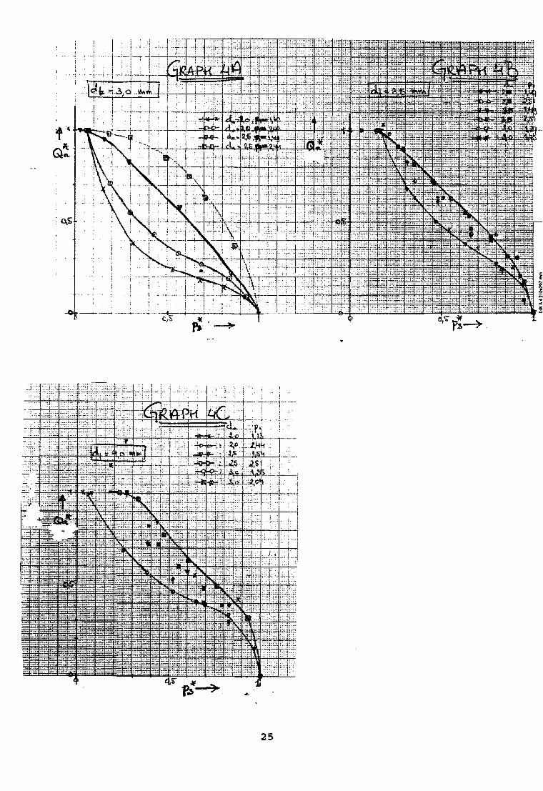
4.4. The relation between Qa and P3
In the graphs 4A-C the air flow Qa is plotted against the outcoming P3. Both quantities are made dimensionless, to make a better comparison possible, by using the following expressions: -- Q~ = Qa/Qao with QaO the air flow when the bottomvalve (figure
6) was completely open (and P3-PgO was almost zero). P3 = (P3-P90)/P3max with P3max tfie pressure when there was no more air flow.
No theoretical derivation was made about the quantitive relation between Qa and P3. The graphs have a more practical meaning: if P3 is known (and now P3 is the pressure of the groundwater surrounding the deepwell pump) one can try to adjust the air flow by choosing dn and dt. It will be seen in chapter 5 that the graphs are necessary to obtain information about the feasibility of the injector concept.
24
25

Chapter 5. Conclusions and recommendations
The most important question to be discussed is: can the injector concept be used to solve the problem of air-shortage in the airchambers of deepwell pumps. The way to discuss the feasibility is to look if the results found with the experiments match with the criteria in the practical environment. This is done in chapter 5.1. Important in this discussion is that the experiments were done under steady flow conditions and cannot be used as a final result, but just as an indicator for the necessity of further research. For this further research some recommendations are given in chapter 5.2.
5.1. The feasibility of the injector-concept
The procedure to investigate the feasibility can be separated into the following steps. a). Determine the total pumped volume of a pump and the pressure
PVQ that is available. Pvo is directly related to the static he1ght Hc (a watercolumn of 10 meters gives 1 bar of overpressure). Both values can be found in the literature (3) and in appendix 2.
b). Graphs 2A-C gives an idea of the Qw that is possible with the various nOZZles, if Pvo is varied.
c). In chapter 1.2. the borders of Qw are given. with this, an suitable nozzle-throat-combination can be chosen. The water flow must be between 1% and 5% of the total pumped volume found under a). If the injector is to be used only part of the time, the water flow can be greater (chapter 2.3).
d). From graphs 1A-C it can be seen if the chosen nozzlethroat-combination is acceptable, by looking if the maximum outcoming pressure P3 is acceptable. If not, another combination must be chosen.
e). Graphs 3A-C gives an idea of the possible air flows that can be achieved with the now known QWI dn and dt.
f). To vary the air flow graphs 4A-C can be of use: P3 is given by the drawdown-height Hp (see figure 1) and by varying this depth Qa can be adjusted. If this depth is not acceptable, another combination of Qw-dn-dt must be chosen, that is, the procedure must be restarted.
As an example this procedure can be applied to the case of a deepwell pump attached to a CWD-SOOO windmill. step a. The total pumped volume is about 1000 l/hr in the case
the static height Hc is at its maximum of 67 meters. In this case the overpressure PvO-Pgo can vary between 1 bar (Hc = 10 m) and 6,7 bar (Hc = 67 m).
step b. See graphs 2A-C. Step c. In choosing the best dn-dt-ratio, graphs 3A-C already
should be taken into account: if dn is decreased, then Qa/Qw increases and too much air is not recommended. The choice is dn = 2 mm and dt = 3 mm. Then Qw varies from 140 to 310 l/hr, i.e. 3-6% of the total pumped volume (if the injector has an effective working time of one fifth of a pumpstroke).
step d. The chosen combination appears to have the best ratio between P3 and Pyo (graphs lA-C). Note that if dn should be 2.5 mm, this rat10 also is acceptable.
26

step e. With the known QWI dn and dt it can be seen from graphs 3A-C that Qa varies from 140-500 l/hr. This is very much and must be adjusted with step f.
Step f. A rough estimation can be made from graphs 4A-C about the behaviour of Qa as the drawdown-height is varied. For example: if Hc = 10 m (Pyo-PgO = 1 bar) and P3 is set on 80% of its maximum, the Qa w1ll De about 10% of the maximum air flow, resulting in a flow of about 15 l/hr. This matches well with the criterium that Qa should be 10 l/hr. If Hc is at its maximum, the PvO-PgO = 6,7 bar and P3 is set on 90% of its maximum (which means a drawdown-height of 29 meters!), then Qa is 28% of the maximum value: this is 140 l/hr and far too much.
A complete survey of the procedure can be found in table 5. It can be concluded from this example that the injector-concept has possibilities to solve the problem of air-shortage in deepwell pumps.
5.2. Recommendations for further researh
Now that it can be concluded that the injector-concept has possibilities to solve the problem of air shortage in deepwell pumps, it is necessary to work out this concept to see if it is also applicable to its practical environment.
First of all, the necessity of measurements in unsteady flowconditions will be clear. Unsteady flow conditions in this case means connecting the experimental set-up to a test pump. Some advices for further examinations are: a). It can be investigated what the relation is between the
position of the outlet and the length of the effective working time.
b). It can be investigated if the injector shows the same behaviour during the effective working time as it did in steady flow conditions.
c). It is recommended to measure the relation between Qa and P3-PgO for more different values of PvO'
d). Afeer the measurements are done a procedure must be designed, which makes it easy to see what kind of injector is needed for a particular pump. The procedure can have the same structure as the one used in chapter 5.1.
27

other interesting issues that can be investigated more thoroughly are: a). A measuring procedure to measure PI' the pressure just before
the throat. The results can be used to verify the assumption that PI > PgO. This assumption was made in the theories put forward in chapter 4.1.
b). The relation between the turning point pressure (Ptp) and the incoming pressure PvO. This relationship can be used to predict the turning-point.
c). The exact relation between Qa and Qw. To investigate this a thorough study of various articles in the literature must be done, as well as a very detailed theory built upon known theories in fluid dynamics.
d). The relation between Qa and P3, which also needs a theoretical work-out before proceeding to the experiments.
28

Table SA-C. Survey of the procedure to determine the feas;bility of the injector-concept, applied for the CWD-5000 windmill with minimum pumping stroke.
Table SA. Step a, band c as mentioned in chapter 5.1.
Step a: He .. 10-65 m .• therefore PvO-PgO .. 1.0 to 6.5 ba r. Total pumped volume ; ~ abou t 103 l/hr.
Step b_and c : • 5uitable-.) d t d n Qw (pva·1 )· Qw (PvO· 6 • S )
3.0- 1.0 1 .0 '" 1 . 5 '" yes 1.5 1 . 5 % 3.0 '" yes 2.0 3.0 % 6.0 % yes· 2.5 4.5 '" 9.5 '" maybe
3.5 2.0 3.0 % 6.0 '" yes 2.5 4.5 % 10 % maybe 3.0 6.0 "10 12 '" no
4.0 2.0 3.0 % 6.5 % yes 2.5 4.5 % 10 "10 maybe 3.0 6.0 % 14 "10 no
') from g rep h 5 2 A - C . ~if Qw < 7 % then suitable, if Qw > 10 % then not.
Table 5B. Step d and e as mentioned in chepter 5.1 (on 1 y suitable combinations are considered).
d t dn renge of P3- Qa (1 /h r)1j suiteblelt#
3.0 1.0 O. 15 - 1.0 180 - 360 no 1.5 0.29 - 1.8 95 - SOO no 2.0 0.49 - 3.2 140 - 500 yes 2.5 0.39 - 2.6 110 - 200 yes
3.5 2.0 0.37 - 2.4 130 - 450 yes 2.5 0.37 - 2.4 170 - 500 yes
4.0 2.0 0.25 - 1.6 110 - 320 maybe 2.5 0.27 - 1.8 110 - 600 no
~if PvO-PgO is varying from 1.0 to 6.5 bar. ~from graphs 3A-C, considering Ow between 45 and 70 l/hr~ ~if P3mex ) 2.0 bar end Oa < 500 l/hr than suiteble, if P3max
< 1.0 bar than not.
29
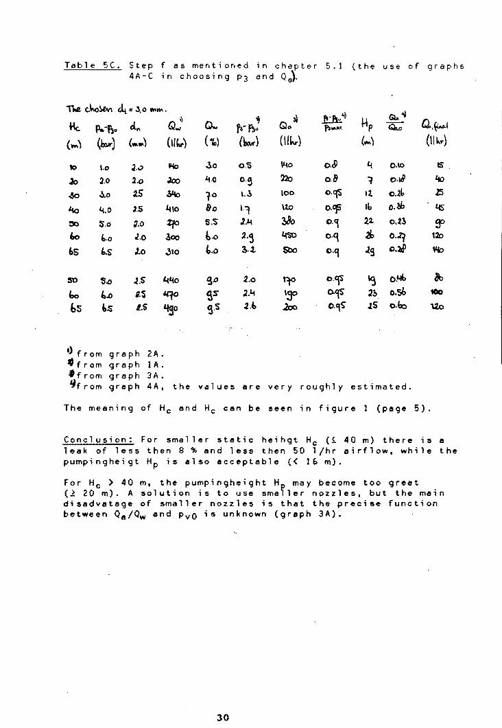
Table 5(. Step f as mentioned in chapter 5. 1 (the use of 4A-C ; n choosing P3 and o a)'
1\e c..ko~ ~ ... J,o W\W\.
~".l Q..~ Q~) 'I}
Q" 3) ttp Me. p..-Ilo d .. Q... ,~-~ .. p, .... , Q.o
(~) (llaK) (Wo .. ) (II"") ( 10) (k) ( 11"'-) (~\
10 \.0 2..;> lI40 30 0.'5 \lio 0.8 ~ 0.\0
.ao l.o .2.0 Joo '1.0 o.~ ~ 0.8 1 o.1CP
.50 ~.o 2S ..Yb 1-0 \.3 100 o.Cf.i It o.1.b
1.1() '4.0 .2.5 ~\O &.0 1.1 \%.0 0.'fS 16 o.l.k
:so s.o g.O Zfo S:S .1.4 ~ 0·9 12- o.ll
iIo b.o .1.0 300 t.o ;Z.~ ~'SO o.q 2b 0.2f 65 '.S 1.0 310 t.o l..t SbO o.q .29 0.21
5'0 '.0 J.S i.«'40 ~.o 2.0 t.to o.~ 'CJ O~
bo 4.0 I.S "'¥' gs .2.'4 '30 o.CfS 2?> o.sb bS b.S I.S 'tgo ~.s .2.1> J.al o.,s .IS 0.4.0
I) from 9 rap h 2 A . "from graph lAo ff rom graph 3A. ~from graph 4A, the values are very roughly estimated.
graphs
Q.,(w.4
(m,,.)
IS
'to
J5
tfS
~ 120
We>
1Jo tOo
\20
The meaning of Hc and Hc Can be seen in figure 1 (page 5),
Conclusion: For smaller static heihgt Hc (~ 40 m) there is a leak of less then 8 % end less then 50 l/hr airflow. while the pumpingheigt Hp is also acceptable « 16 m).
For Hc > 40 m, the pumpingheight H may become too great (1 20 m). A solution is to use sma~ler nozzles, but the main disedvetage of smaller nozzles ;s that the precise function between Qe/Qw end PvO is unknown (graph 3A).
30

LIST OF REFERENCES
(1) Intruduction to wind energy , E.H.Lysen, may 1983 (2nd edition), nr. CWD 82-1.
(2) idem.
(3) CWD-folder, at the back of this report. see (1) for the formulas to convert the specifications given in the folder to usable quantities.
(4) studies on gas dispersion in a horizontal liquid-jet ejector, by M.N. Biswas, A.K. Mitra and A.N. Roy. Paper E-3 of the Proc. 2nd symposium on Jet Pump & Ejectors and Gas Lift Techniques, BHRA Fluid Engineering, Cranfield, U.K. (March, 1975).
31

List of syabols and subscripts
Symbols
symbol meaning used S.I. dimension dimension
diameter am fraction of total suction used
in an injector the power of fs pressure bar
n p v A o
velocity
01 He Hp Eel
Es
M Q R T Q
Ii
~
cross section area a constant defined as
C = j~(~v~.=R-.T=-.=Es~.E=e-l--.f~g~)~\ a constant defined as C1 = ,J(E,.Eel.fsr the static height of a pump (f1g. 1) the drawdown height of a pump (fig. 1) head loss factor because of the expansion of the waterjet after the nozzle head loss factor because of the
mass flow volume flow gas constant temperature
flow pattern of the air
ratio between An and At ratio between At and A3 density factor to relate ~m to ~v
l/hr
subscripts
subscript meaning
d g m n t tp v 0,1,2,3
diffuser gas mixture nozzle throat turning-point liquid see figure 5 (page ').
32
m
kgs'm'l&
m m

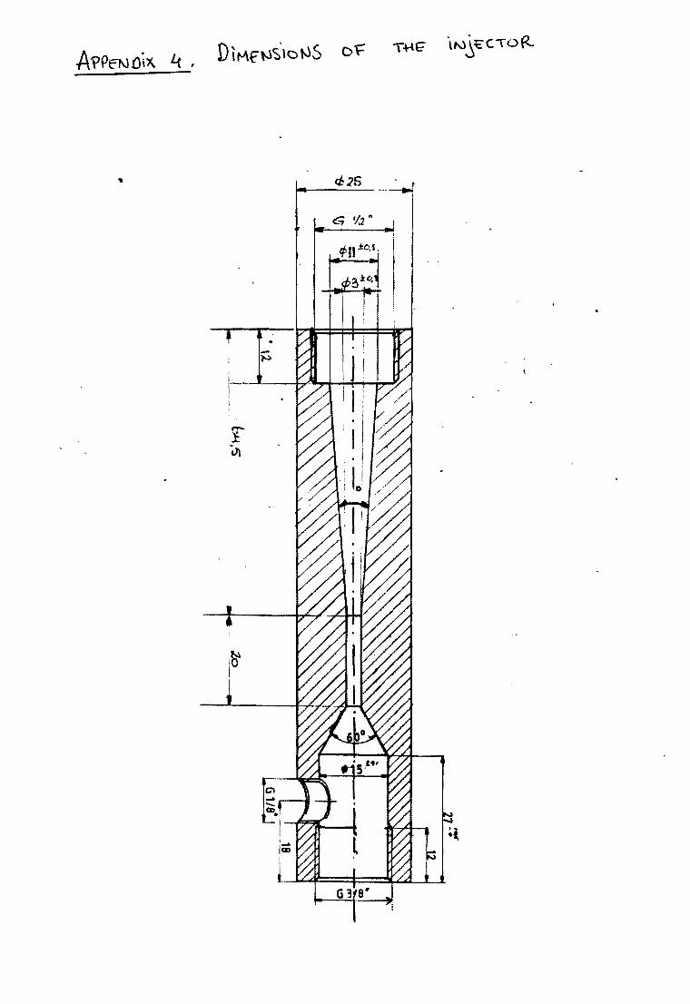
A'PPE"""'.(HX 1 t?xPER\Mf~TAL ~.E~UL:TS ==-
In -t~ -\oHcWi~'.~ -\:a.bk-& -tW. to UC\I.J\."'5 ~~ols (lfe u.1'.QJ 'p-.(O - r~" ~ kvvoWV\ V WeJ.ev- : fu \/otAtw.-t- 0\ ~ ~*{W" ecJc1.Jd. ~ a.. pMtak o{ tlV'v'L. fu
.n~ IS rOOv\ l.Y\ ~ ~t<.J c.ctM.VV\. V\ .
\J' wo..hrv- : fu ~al"\ ~(.. ~~ fu ~~w.w. Q: fu vJQ •. A~~v ffuw , ((\,lt~~d fv'tYM V V'otd~(' aN\J fu ~~ . QcJ.", fu. cJf~ VV\J2a~ec.t Q~'i ~ \J'>M.Q.M ~ of fu u.,~~~.
P -f fp \ ~ "-"""""" ~vo -r~v) ~ V\1c..e.~~ -b yb~ ~! Q~ -c.
Ta.,ble ~. d \a ': 3 If{I.v'V\.) dV\ -:- j MW\
_ 3(~ -',j • t~'it ?("j)(~) .~, ~~) 8ft)
33

To-kk A .1... dol =~ W\'N\) dV\::: 1/~ VVt.Wl
, ~~._~J~\_--~ tl~e ~~~=t-=(f~~··· ,. (~~. -
Vw;...'\'eV-~ .. ~o ttw\e ~ c..!{) lvJ\ ~,
o,50~ 'y'l c'l-\ ; 8-;, :,.. .. :) .~, , .... / ........ '- L~
~,c 1-! ~,~! ?!}i h~o;1&O b 1:~t~ 0)01 o,::.?: o.,bb/qbc ~,,,,,
~/:YI tJZ<-,:>jfu,1 1.}q ~ ~,~j '15 2 ,'Sl ~ ~(o 1 ~"t:cJ ~';;2/~~ 1~ ~lo2>-io,C! &22/ 25/ 23 11 ~~~OfOJ /ibI;, 8b~8b1 12, 3,~!-t.opl B3':)18J.)[&J) , 12. ~,1<:!-t 0,01 1\Z·/1\ol~\'~ I jo u,,4~-! Op1 l'3ti/t 3Z{130 i 10 L! !O O! LlQ ' :l2 S Jo 1~1 ,
- ,.- I \/wJer: QIoV l.wJ) I (tj~V") i
I I ,
8:,1-!: .t t<»! 1 te8!:.~ tLU -i:.' t,i4 '14:: :2
±3 19'3-±' ~
~-!~ ~l!-;4 l,±~ ~1iS"
abH~ 2?03tS ddj-±b lbS-i-b ~\tH5 25~i1 1b2~ lbtab i
SH! I o-!.b I
1'.Lilt 1 '\t)ij,o± 0,5 .1Lta-t 1
.2Sct± 1
• Q. i
l~/~ !
,.2~1
t>t-i. J 1~S-i:.1 J3bt.1 ~iSiZ L:r.lS,* ~ b2ot5
~rt) to1:s/UO,Sj1a5,O i 1cb ± ~ '2kp/i~i5{12~ ,0 12.b,l!D,s ;)t;)2.1 to 1/ ;2 D2. 2D1-:11 22.~/ 122/222. 222 1: 1-2.b4J2!l(11!~ 2b4il 2bs/2b41::11 2bi f 2. 3t4/31b/312.. ~lli-t 2. !t"'t J~\2/~\'1 3\312.. 3\b/~oJ31b !tl!2. 3'!k1$-i/~3b ~~,2, ~bb ~b8 3tk !h -:2. I I
. ..,
"'GJo1e A.I..(. d.t = .3 ~'M) dV\ -= 2.,S V'I\\M •
o,5t!-!:o,Ol O,~~ ~OIOl 1,S2 -! o,oj
'.~'"!:' 0,0 t 2, Lf,H' 0,01
2,~tO,ol ~,~C'~O,Ol Lf,So~c,O~
~'i.3 171-±~
'fH:5 ~\?"i8 ~±8 4~i'O Lto~tl2.
1~~1:\2. .
34
~tt~) (~/t) 83,~/82/SJ&3,S 6l,.1i.qs
~O/1~,o(~ 4ob,~q~ ~~b,o/1\5,S/t\S/S, US.'l-to,S tq,o/t11,S/11~$ tq,!-i 0,5
""S/11S }W .. t 115-1:.1 1081iO~I\08 1c9-!1 12~ /u.8/425 -\281:.1 1Lfl?/ tSO/iLti 1tt1± 1
,
0,\8+0,01
o,'b~:!:O/01 .O/fLH:/:f01 o,St~o,Ol
o,satop { o,bbto,ot G,cPiO,ol o,~!to,01 i,fofO,Ol 1,L(~t 0,01
p!(~)
O,2b±O,OJ o,50±qot o,~LijqOl
O}~:±qot 1,2.3:to,ol i,LtS'-± 0,01 1,:tOt~oi
1,<3' ~O/Ol 2,~-fqol 2. 2OiO,ol , ~3ioo
, !
0, 32d'±D,OCJ. 1,.;>30t 0, ~ l,~tO,oo! VbS±o,ooL 1. $21 'i 0, DoL, 1, S~ ±o,OOl1
,:.L 'iI (, 0fC13i 0,£0 .. ",~lii:O/oo3 1;1l>f±op0.3 l,C>1o±o,oo; 2,~Hqoo.
\( f7~'1
q~1±o/Q) i,cx)s!.o,
t/~±4cO, .... 1,lHl :ro, 1,~to,c03 1,~t-=O,~'3 ~'5±o,oo.3 1/~tO,oo 2,~ti:o, l/l1D'±o~
. :1 ,JLf~coo

\~\e A.'5". c1~ = lJ,'S w\'M) din -: 2 W\~
V~ I t::'rW\£. v: ~~l ~tt~) -
~3(~ 1 ~1hJ~' . ~l~) GA'ft. ~.) (~) (~ (tt~)
O,5Lt-±o,ot ~~.2S/t'~'S .:!:O ~',.~ 8 11Oi: 2- ,ob,o{lC8tollo:vs tcq,l ±O,b 0,23+0,01 0, ~5±:D,oq . 1,08± o,ot :8t.t'11 2.1 iL(o .10 ~!,.±Lt 'I52f z. 1w,';i/\2~lol\2b,S 12d,b-!'-O,5 o,Lt!;!'CI,CI \,~~OoS ..... 1t
Lfli:o,01 :rM'/~t \5 ~±3 t~1: b \4rcl~I.o/\~,D ''fO,~to,S o,7t1o,Oi 1/2f~-± ~oo~ , .1,02 ± 0,0\ ,lfbt.tl ' 1S a3 2Df i a, 14 ,O/LI.ctP,S/ILt5.'5 l~a 'i'O/S' o,~±O,o' t,Lt2f ±o,ooLt _ 'l,5H: 0,01 S /fjlo/tff'i IS
At~ J~..t.~ liBs /2tJl.t 283 ± 2- q~r!O.'H 1,5~tqOO! . .1,,11 ±opt 18\'/~ u. llM~t J.U.B/.24:3/24.9 Jtce±l 1, 06± ",0 J iJW :i:l)oo3. .2,<01 * o,Olf '1,1/ :;O'ohi2 12... ~5 W~5 /'$".llg5B 55.31:4 1,1:-tqcn .....
r'~-OPI . .sp1t o,of.{ ~ 12. 1C9ot~ 234*1 2~1ZS/.241/~ 14i.t±.3 1)1~-±0JOf ,,~S-:!O/C1 . 3,!fito,o1 i1'tlt=l~I~~ 12.. r:~ 222-!:5 21.,slzbbI 2b=l 2bb±1 1)2b10,DI 1, :<9± ~oo:.. .!>,si..to,oi. . ~'t1'~ .'\2. -!:Ls ~1:\:5 ;r~t lz::n/ ~1 2iHt i,Y5±o,o1 1, e8g to, 0<:'3 It,ob ± qpt ~c1 L9t.·U ac..., _tl '&LtS"-i:lf 7!!k%'; ~J2".34/~':>~ ~-12. lS4±q01 2of5±ooo?.
j. • '
4,~±o,01 :g.25/Sig/~14 1,t ~zbt~ ~1C>ib :JI:j2/uYS ,~3 ~1±2 l,<9b-:l' 0,01 ~ '2!~:fqro2
T~{e A.b. d.t: ::: b,5 tMVV\) cl~ -= 2.,S w.."", •
\J~ L~e - - -'i~kr rVO((!:) \1.,., flit) Qw.r ~ fsM:) ("",l) (co) (wl) ltliw) (tllw) r
Otb4-: qo/ ~hssl1-sOl \5 1~0>~~ 1dH:b \21,o/\2'1,SI12b,s l.21,ofo,S o,29,*O,CI o,c?cio !Cl,CX: 1,04tO,01 ~"6SJ ~41 ~S~ 15 ~SLf~b 2~+'5 '\rsg I 'bO 1 \bS '\bl'i 2. o,4i±O,OI t,OJpio,tc V-\!H.o,OI ~Q;)/~1.t/~ 12- W~-±'3 .21 'i S 2.~/2~2123b ~!.-! 2- %3-:c,ct t,2~to(cc 1,~1:0/01 101&1!i1 10 ~±:5 ~2:t tJ) 21.:(t /2Lf1l/2Sb J'tY± 1 Oa?-±o,oi ~~iq~-C
2, -t0rol ~~I&f~~o kl 8c9C3i 3 1J 0:' J J5S/15b/'lbl 2'58-11. I
o,rT4-:fC,cl V~.lJ:"tec l,Lt~-:!: 0,01 ~'50/~4 ~Lf9 110 ~4C3!3 YfH. Z11/212Jl12 .2,2-t I c,~c~~alol 11'Si~o,e .1,~1-!o,OI ~,dl/~\sl~\C 9 ~~-iL.t ~b!10 .29~/~412q!; J;:{Lf~ I 1, t'1-: (', 0 I IJ'P~ -:!(), It,oHO,ol '~1d)/~\2{~lb ~ '(H~ Lff1± 12.. 3Sb I '" ~ J$t'j o'5(P±l 1, 54-±o,Oi 'J..jXJ~to' i{,elto,OI " ~ ell c ±4 4,,1'± 12. ~/$a,bl I.-f Lft z.. I Vi s-± 0,0 I 2; f2~'!r;CO
To.b\e A.".. 4::= 3}S vv\VV\ ) cA ~ '::: .3 Mw\ . }
", Vw, - .
~p..,~~ fw~ v~ -b.~ (Ii) ~al~ ~t) ~(~~) (wt) (s1 (Mr) ~ i"-r)
o,'55!. 0101 1~8/~'~ t1 l~i:Lf 22l:.-i S" "0.3, 0/10.3,~' tOI/:I; 102,~±~b 0, 2k± 0,01 oa~.uqc.n:, t,OS *:.0,01 ~11 o~ 10 842±~ ~±t 155/ Is.! 11s5 '54! 1 o,4'1-! 0,01 I,()~:f o,ODS !/~i::'o,Ol ~1t9/~2o/~O 10 ~1b±5 =~~ ib~'''h3 , Ii::. 1 1b2:! 1 o,s?:t,~cl \ 1 ,q-! c, COIf t,Slt 1:: D,Oi ~;\bl~1S'~ 9 t~3 3bi±9 \1# J'JlI1lQ 11ci -t I obe-+oo' 1,.1-41+ C?~ , - J •
1.15 -:o,ot c=l2/,a661 . C' 8 Lf±5 ~.!.! .2 1&~b 1/1 ( i(9'I-i 1 O,1dtc,c/ 1.3~3to~ ,,~±'oJo' 'j~/C32e/~22. {j Q~-i.'i Lfiii.12.. iNS' t~111~\ 1~1± 1 O,c?1 io,ul '.+ V·4 ~,_ opoLl 2/-to-±qo, C?8sl ~!>I tllJ& 1 ~s Lf51ttO 1~l/301/tg~ ~1 1,0<4 '± 0,01 1,r;;~S!O~ ~)os"!;o,o~ . ~bo/~50JS511 T ~~it ~-!1i iba/2bo(2bl til ·4 ~~ ... o 01 \.~~i<;,c:c3 , • J
35

Tilie A. &. dt- =·Lf WWV\) d", -:::. 2.- IMWI
,,~ - - --
p\M)(~) t\~ 'J.,., Q"" QA\t' ~M~ ~Io ~~-~ (tMT) (~) (w-t) «!~r) ( (/tw") (tfh() :~
O,5.l-t.c,ot ~30~$~2J) ~ 92Jl±~ 1\1±.1 g~p'a,o }~/S &',Bto,ii: qtl±O'O: Oa~l±C!OC '.q*op' 8:ft1 aOJ ~ (jS>o'H;- tsC'±2 118,0/11&,5 Ji20p 11Hls o,b q:fH:O,i:l ! 1,cxf.2i D.O~ 1/51-: 0 , 0\ 3J3f:;J~ ~ iooo±.'; 18012.- ~fqp'l ~,Ol\:z.o,o 111»tO,S" o,LfLi-i q C I 1/~f"'004 1/~-.t 0,01 &511 I 15 ~t3 2ei-!: ~ 2~ /2/;0/21,::, .25~"i 1 0, '5& :±-o,':> I 1,l-\Qlf:!O,o~ J, -!O,OI t~~jto 15 ~b±3 23'1f li . ~/2Sj/2S{{ ~tC5-t: J.. o,13~o,o! 1,~ic,oc ~12:±o,o, 12. C9s~~ Z'O-i5 314131S/~ ~±'l' ~Q6~D,01 ~1~biqoo.3 o;~-t°rot t;st~1 f?P. .~ 1,1 ~~ ±l 2b3~'f &Jb'jM11~' -±.:b O~i±qDI. 1/6!t~-! o.oce :,S,'Ho,oLf e~/()lZ/a-J)) It &i-t-t3 .2s>-:- 5 . 3tjS/;t/ 'JIj4 ~~2 0'5 ~O,OI 1,M?t.: 0,01 3,c9s-to,ol B~ I a~l~8:!>' i2 8~1:~ .2SH:: S ~/2 12'12. "J -i'1 \0"2:1 0 01 11~±o,0Q3
2kr!S ,
Li,13-t q "I ~/~ ~bs 1.2.. "t±~ .2"5~/.2b, /?SO v -!: 3 1,otP -t 0,01 l(o?Jiq~
'-\~tqOl 85¥/~/~t; 12- &il-l~ 26q~s .2~1 t:l l1/.213 ~~21: 1- 1J1f±Opl .2} 11~ic,oo. $',0 {O,Of 'i1 Q 12- -!:S :let"! b 2. J ~ i4 1,32~ODI ~tD,D(,
3
2,
- --4:w - - •
~~~ ~~-~i~ 1'11t) "(:tr \I""" 8-~) QIH~ . f~ff. (t) (v.!) ttl~1 hv) (b.w :<~
°tJ)t;:O,OI ~/'i\lI=tIS 15 =t"±Lf 't\± ~ ~t;;{~,S{bI,o b2p~ 0/5 o,2H C;.)l 0, i!>~-t 0, cO i)1H:O,o \ ~f:JgoJ~ IS' 994iS .2~-t4 14,o(14b,O/:t.b,o 1'Qk!q'1 () zqJ. l " :\/ ~ci6'4-to,oo
t ..... "'" '" 1-
1/i1~ 0,01 r:JK)J~IS f2. ~5 2~~i b fDPI1(?~j '11 ..aD"'!: I O,t{o,":"D,O. ~tJ.z~ 4ry:) ~o4'.'!O(O( aas~~ 10 'i5 ,.3(cP-f 9 2:jbi 3 b/~' t 1 LilcP.: 0 ~1$1'2~2J'1&2 0, t:--:0,01
~O±a '. t
2,41-1'101 5lt1/S4lJ Sl£ 10 ~'M.t~ .3SsJ~S<.(/J5L1 ':';;>4 ~ (. C/1S-± 0,01 t~J:±o co "!.k8.1:'YQ
I . ,
~t~rto,ol 921/~~'S- ~ <32ot5 3iP1/lt:113Q'Z. [ ~C'-! Z. o,Cb-to,ot rf'P~~ OJ 4- ~+OfOI N (:\1 (Q ~3 <414-: 11 4tq~b~ t{b~ Ltb!"i'5 11 tt-± 0,':: I \ I 1,i-to! ';1)
f t'"
z
'1 ....
,,~ - --- - - V'" ., 'wi~ .uM~ \tW ) &,~~ GtIIo\r QiJtt f'2(~ (w-.f\ n) (..;J. (,t" ((Ikr) '.tl~) f7~'1t 0,,,1> -10,01 1~/1?;1 12- t-!3 221~S t1~o/tf\u~S H1/fO,b 0l'l~ioJot 0;:1.4&: 0p>'1 .,oS-t 0,0\ 04ciql.(~ 1~2. to is 3fj4.t8 2.2&12.~j 2,lQ t 1 o,4CtC,01 1 :;)2 Sf C as jS1.!. 0,01 ~~J~I,;l/gI1 .3bS~3 .lbr~ '1
' . I
~ '312*~ ~21:lb4l2t8 O,s8topi 1,.~.H 0,004 ,00-: 0,01 ~/FJSl~1 ~iLf LIIC\~ll .:!;1Z/31Q/3t~ ~t4±2.. o,f5tc,Cl f,~i4fo
.1,~l-:!: ~o.O o d'S,:} ~1: 460' "1 5:'5 ;lb .3?:!E:it 1~.3 ~12!l O/a2~ 0,01 t51. io,cA 3,~,* cpt.{ ~1~J:l' t ~c:e~4 lfbJ±IS ~qs/492 I..f ~ f~ 5
. ..J 1,3b-topl 1,10 ~O,OI
36

qooiO,ot q10 -:0,0\ 0,'1.0 to,o I 'i31 to,o' 0,40'*0,01 O,'Sl l' 0,01 o,:s:r:! 0,:1 -
Pp~tt:) 0,11 'io/ol 0,21> 't%J
tlL(~
O,~ -1:qOI 0 /40 -t~OI 0,$1 i:o,ol 0,4>0 -t(),Or o,bl.l -to/O, ---
1t.to. Q -!: 0, S 1YLl -I: t 9<91: 1 {,4±1 61 :t. i 35/c.:; =o,~
o
b. ~ ttl t..«.)
. 23\i.1 : lOS cP '!; 2-
.- JlS~1
~~~qs fer. lP>i: 0, & ~3>,S'i: o,~
0 ---
D,ob:r11 01
0,20:-0/01
0,31.1:'0,01
O/43~o!CI[ : O,b\.{-tO,OI ! ci1C'±O;01 ' oJb~-t ~,Ol O,31:!~O'
'282>± 2-:211>:;1 ;;o~ t 1 i,cP± 1 -t~i: 1 HS* f 8y~ I
o
:l,st kw p3(l-xw-) ?SA (tltJ.)
0, \~ -kO,Ol 2151:. 2-0 1 2.S -t 0,0\ ~±f o ,'ll.( ~ 0,0' ±1 O,I..(S:t~ot 19b :t1
O'rlt'f 0,01 1,2~ t .
0, '-t to,ot 1""'-:1: 1 Q"l~.tQOf 115~8t.o,s 0, Ott "* '10 I Bs.l'S i:O,~ O,~1 -to,ol 5S,} fo,1I o ~O,OI 0
37

f -P. 11: .~ hew' P'; (6.)) ~ ell'M.) p~ (bwl ilb;;~Iki<.) o,'2..±o,O\ ,i>1 ':'1 o,o~-! o,ot k*t ~'2.~-!O,O\ \bl-t 1 0,t1±. DrOI \1£1: 1 (),~tOfO\ . 1~'\~ 1 . O,lt:P ~ 0, Of ~lS:tqS: O,~-t. 0,01 ~*1 O,UJ±: C,OI T"/2.':J:~" o,bO±o,Ol 13,O±O,S O/""&'fl: 0, 01 8c3,)!:qf o,~to,ot 31i.l 0f~ -to,::>! to.'Ito,S o i:)tD-!:o, 0 \ _.0 Or'S'~tO/OI 0
~ --t--- - -
t> •• p:~ 1)~o bc:l)lt. 2,i.tt.( ~ ~(~(~) ~~(b) ~(el~)
0,0\ ±O,O\ 111,8i:. o,b o,a.-t-t.Op' 2g1.(,± 1-0,0{, :to,O\ '?9,t -to,b O,11j-O,O\ 202. t 2. O,~ ±o,o, 81,OTO,b q2b~o/OI \~11 C,2.\-!: 0,0\ . ~,S±O,e 0, ~ to,o2 1S(9± 1 0,29 i:. 0 /01 e:q,~:!: 0/1 o,4t1± 0,02 11b,~tO,S o/~1.±o/OI . 0 0,'51'1" 0,02. too,5i-qS
- - O(~±o,o2 Lf2a'±O,i-- - 0,1;. ~o,O'L · 0 •
f~o-Ps'> 1,54 b-. .:zS1 bwa.. p~~) . Q..CeIW P.s (b-vtt)' G5"o. (~/~)
0,04 *0,0\ 19°-;t ~ O,ll-!O,O( ~±'1. 0 ,\4. i: 0,01 ~S:1 °,25-: 0 /01 W~2 G~i:o,OI 1bH.~ 1 o,.:s: 0,01 2.~± 2 o,~l i: 0,01 1Ol,btc,~ 0,45"*0,01 27111 q4Lt:t:qOI =t$,hO/~ O,'S'ltO,Pl '~S:!:-2 ~S~±o,of 0 OaO±O,OI 11b~ 1 - - 0,15=0,0' 0 .
. ....
~ f""-~~ 2,cJ..i 1,.35 · bcvR. t) ,..,( QQ,l{IWsz.) ?3(~~} 1ifo. (.el ~ . 0,2\"* 0,0, ~ott. q\Lot to/ot 2Li'1.t 1 . o,!J.(i: O/of ~~1 o,1cd-opt 1ioi1 c.,4'::o,o 1 'S3 * 2- 0,21 :ro,o1 ~1,2+o/~ o,'S~to,oI 1~2± 2.: o,~4±o,01 102.,2.i.o,5 O,b1 to,O\ 123,11: O,S o/t.f~±o,o1 :fttt
. () ,*001 0 O,52.±0 01 · 0 1~1 I
-t) "f3 .. ..f.s ~: f3 - ':5" 38

(..I. ~>l
0.77 0.'33 1 .09 1 • 22 1 .53 2.05 3.01 4. 11 5.03
1.0 mm
U.71 1 • Z 3 3.58 4. 16 1 .55 2.27 3.26 3.35 3.94 4.87
d n c 2.0 mm
0.54 1. 08 1 .47 2.02 2.51 2. 71 2.92 3.07 3.34 3.57 4.06 4.92
Qe. Qw
0.97 0.85 0.80 0.71 1 • 21 1 .02 1 .52 I .04 1 • 1 4 1. 12 1 .31 1. 41
TcJ,le A.le.
d n - 2.0 mm
f\>-&' t:-0.52 0.75 1. 17 0.75 1. 51 0.66 1 .97 1. 26 2.58 1. 09 3. 12 1. 46 3.33 1 .47 3.53 1 .58 3.85 0.95 4.13 0.98 4.49 1. 01 5.03 1. 04
6)" 6:C
O. ~>3 1 .OE> I .4 b 1 .60 1 .76 1 .79 2.14 2.51 3.10 4.04 5.02
1.5 mm
c.Qc..
Q ...
() .lW 1 .35 1 • E,5 2.72 2.75 2.01 2.23 2.51 3.00 4.03 4.66
d n • 2.5 mm
0.64 1 . 04 1 .45 1 .69 2.02 2.49 2.97 4.01 4.52
~
d n -t--f\o 0.58 1.11 I .47 2.04 2.47 2.91 3.89
0.70 0.70 0.85 0.85 0.81 0.80 0.80 0.87 0.91
f\ll>- ~o. 2.5 rom
~ Q...
0.36 0.62 0.69 0.87 1. 04 1 .06 1 . t 2
39
0.50 1 . 01 1 .51 1 .99 2.52 3.03 3.44 3.93 4.19 4.45 4.77
2.0 mm
1.0f 0.89 1 . 1 6 1 • 12 1 .05 1 .08 1. 21 t • t 8 1. 23 1. 27 1. 36
d n = 3.0 mm
p.--f!So 0.S5 1. OS 1 .27 1.54 1 .75 1.99 2.40 3.05
Q,. Q;"
0.45 0.51 0.49 0.49 0.4f> 0.46 0.44 0.53
d.t -: Lt W\YvI •
dn - 3.0 rom
f--'~ ~ Qw
0.56 0.51 1.05 0.75 1. 52 0.72 2.00 0.75 2.47 0.81 3.10 1 .07
d = n
p..,' p~.~ 0.58 0.99 1 .52 2.01 2.49 2.99 3.98 4.60
2.5 mm
QC\ Q':" 0.49 0.48 0.42 0.37 0.34 0.30 0.31 0.34

d n=2. p = 1 • E.2 d n =2, p =2.42 d n =2.5, p =1. 43 d n =2.5, p =2.44
r,-fu ~ ~-f\,: Glc l?~ Q". ~rfl-' Qc.
~ G;:"" - Gc ... p~'I\O\D." f>:l-.l p~-,,1( Qo..:, ~'*"""
O.Ob O.Ob 0.03 1 0.07 1
O. 15 0.&8 O. 1 '3 0.71 0.16 0.95 O. 18 0.98 0.31 0.38 0.30 0.55 0.29 0.83 0.30 o . '3 G
0.53 0.24 0.43 0.43 0.57 0.58 0.49 0.85 0.68 0.18 0.56 0.33 0.85 0.21 0.62 0.75 0.81 O. 15 0.69 0.27 1 a 0.71 0.63 1 0 0.84 0.19 0.87 0.37
0.93 0.0'3 1 0 1 0
TJo\e. A .22- ~ - \l'e..{'wt ~) -p~:! c4 -= .6,S Qa,v 11 ; Y\I\."-It """\IV\. .
d n =2, P -1. 47 d n =2, P =2.51 dn=2.5. p -1.49
ft.-~ Gb. fl-~ Q.:. ~ G)n .:.--;;...-
~ ~ ~ f,_x - p). ........ t'l-0.00 1 O.OG I 0.17 1 O. 18 1 .03 0.21 0.'38 0.31 0.68 0.35 0.63 0.35 0.72 0.47 0.50 0.54 0.46 o . 51 0.63 0.63 0.38 0.70 0.36 0.6E> O.4E> 0.80 0.27 0.89 0.25 0.80 o . 4 1 0.94 0.15 1 0 0.91 0.30 1 0
1 0
Ta!,\e. ~ 'P~ -FojO A.Z2>. tSln,o ~ fl,W\N( • cAt = '6,S WVM..
d n ",2.5, P =2.51 d n =3, p -1 .27 d n -3, p -1.75
~ G.c. ~ ~ a:&- Ge.. Glo.o PI~1. Qcu,
" .. cU Go ..
O. 15 1 0.14 1 0.15 1 O.ZE. O. ~.H 0.31 0.83 0.29 0.90 0.35 0.81 0.48 0.61 0.45 0.72 0.46 0.71 0.66 0.43 0.63 0.55 0.S5 0.63 0.83 0.24 0.77 0.40 0.65 0.53 0.'35 0.07 0.95 0.17 0.77 0.42 1 0 1 0 0.86 0.31 0.93 0.20 1 0
40

dn"'Z, p '" 1 . 13 dn-Z, p "2.44 d n =Z.5, p '" 1 . 54
f~ Qe ~ f?-A., Qco-.;...---
Q<w ~ p..-.x f"J~"j(
0.03 O.OE. 0.08 1
O. 18 1 • 15 0.25 O.b,:! 0.25 1 • 29
0.3':1 0.72 0.38 (1.57 0.43 0.85 0.04 0.55 0.52 0.47 0.60 0.57 0.88 0.42 0.70 0.40 0.83 0.40 1 0 0.83 0.34 1 0
0.<:37 O. 15 1 0
d n "Z.5. P "Z.51 d n"3, p -1 .35 d n -3. p -Z.04
~ Gr.. ~ Go.. ~ts~ ~ P- 'Q;;" V1oi\O.o-.Y Qo. ..
0.Z3 1 0.27 1 0.27 1 0.33 0.':17 0.38 0.73 0.44 0.72 0.47 0.77 0.52 0.53 0.55 0.60 O.GO 0.G3 0.65 0.41 0.69 0.48 0.7E> 0.49 0.83 0.30 0.79 0.39 0.<:33 0.32 1 0 1 0 1 0
41
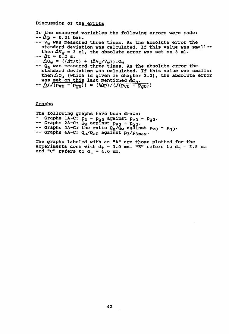
Discussion of the errors
In }he measured variables the following errors were made: --QP - 0.01 bar. -- Vw was measured three times. As the absolute error the
standard deviation was calculated. If this value was smaller thenAvw - 3 mI, the absolute error was set on 3 mI.
-- ~t - 0.2 s. -- ilQw == «ht/t) + (Avw/vw» .Qw -- Qa was measured three times. As the absolute error the
standard deviation was calculated. If this value was smaller then.c1Qa (which is given in chaEter 3.2), the absolute error was set on this last mentioned~a.
--I:l(/(PvO -'PgO» == (\8p)/(J(PvO - Pgo»
Graphs
The following graphs have been drawn: Graphs lA-C: P3 - PqO against Pvo - Pgo· Graphs 2A-C: Qw against PvO - PgQ'
-- Graphs 3A-C: the ratio Qa/Qw aga1nst Pvo - PgO' -- Graphs 4A-C: Qa/QaO against P3/P3max'
The graphs labeled with an "At! are those plotted for the experiments done with dt ::: 3.0 mm. "B" refers to dt == 3.5 mm and "C" refers to dt - 4.0 mm.
42

APPEHDXI 2
Calculations of nozzle-diameters given the specifications of the o.D-5000 and the CWD-2740 windmills.
If the pumping height Hc is given, then the overpressure ~p, defined as Pvo-Pgo' can be simply calculated with:
Ap = O.l*Hc •
The velocity of the water going through the nozzle can be calculated with Bernoulli's law:
~ = \.V~l.gV. Than vV1 = Ir(-2-.1-0--~3~.~~-p~)'. With this velocity, the wanted diameter can be found with the relation:
Qw can be found in the literature (3). Note that 2w is about 5% of the total pumped volume. If the injector is working during one fifth of a pumpstroke, the Qw during this time can be 5 times as great (because Qw=O during the rest of time).
In the table below the calculations for various possibilities are done. The dn calculated in the fourth column refers to a mean value of the water flow through the injector, Qw' of 1% of the total pumped volume Q. The fifth column refers to a mean value of Qw corresponding to 5% of Q.
43

Table A2.1. Calculations of the wanted diameters of the nozzle.
CWD-5000 with minimum total pumped volume. Q == 1000 l/hr.
Be p vvl dn dn (m) (bar) (m/s) (am) (am)
10 1.0 14 1.12 2.50 20 2.0 20 0.94 2.10 30 3.0 24 0.85 1.90 40 4.0 28 0.80 1.79 50 5.0 32 0.76 1.70 60 6.0 35 0.71 1.59 67 6.7 37 0.69 1.54
CWD-5000 with maximum total pumped volume. Q == 2600 l/hr.
Be p vvl 4n dn (m) (bar) (m/s) (am) Cam)
10 1.0 14 1.79 4.00 15 1.5 17 1.61 3.60 20 2.0 20 1.50 3.35 25 2.5 22 1.43 3.20 27 2.7 23 1.39 3.11
CWD-2740 with minimum total pumped volume. Q == 800 l/hr.
Be p vvl dn 4n em) (bar) (m/s) (am) (am)
10 1.0 14 1.03 2.30 15 1.5 17 0.94 2.10 20 2.0 20 0.85 1.90 25 2.5 22 0.80 1.79
CWD-2740 with maximum total pumped volume. Q == 1700 l/hr.
Be p vVl dn 4n Cm) (bar) (m/s) Cma) (ma)
10 1.0 14 1.43 3.20 12.5 1.25 16 1.36 3.03
44

APPENDIX 3
Calculations on slightly altered models of the injectorconcept.
a). PgO f P1, but PgO = PI +~P1·
Rewrite (2.1.12) and divide by A1:
(Pgo - ~P1) + 2 (PvO - Pgo + .6P1) . (Av1/A1) + 2 <LlP1) . (Ag 1/A1) = P3 + (PvO - Pgo + .aP1) • (Av l/A1P • (1 + (A1/A3) 2 ) (A. 3. a.1)
With inserting a and p and realizing that (Ag/A1) = 1-a :
PgO - P1 + 2apvo - 2apgo + 2a6Pl + 2(1-a~p1 = P3 + (Pvo - PgO +Ap1).a2 .(1 + P2) (A.3.a.2)
and so
P3 = Pgo (1 - 2a + a 2 (1 + P2» + Pvo (2a - a 2 (1 + P2» + ~P1(1 - a 2 (1 + P2» (A.3.a.3)
This can be rewritten as:
P3 - PgO
Pvo - Pgo = 2a - a 2 (1 + P2) + ---- (1 - a 2 (1 + p2 ) )
Pvo - PgO
b) . fm f ~v' but fm = p,~v' with P, < 1.
Expression (2.1.4) changes in:
Vm2 = (vv1/P,). (AV1/A1) (A. 3. b .1)
Expression (2.1.10) and (2.1.7) give (PgO ~ P1):
2 Q 2 P1A1 + VV1)V1AV1 = P2A1 + P,vm2~vA1 (A.3.b.2)
P2 = P3 - ~P.Vi2~V.(1 - (A1/A3)2) (A.3.b.3)
which results in a slightly changed (2.1.12):
(A.3.b.4)
If a and p are inserted and after some rearranging this can be rewritten as:
P3 - Pgo
PvO - PgO
45

c). No diffuser section.
The derivation of the equations is similar to the derivation done in chapter 2.1, with omission of the expressions involving P3. Starting with equation (2.1.7), inserting (2.1.4), using the Bernoulli-equation on the section 0-1 for the water and dividing by A1 leads to:
P1 + 2(Pvo - P1)·(Av1/A1) + 2(Pgo - Pg1)·(~1/A1) = P2 + 2(Pvo - P1).(Av1/A1)2 (A.3.c.1)
Setting P1 = PgO and inserting a gives:
PgO + 2a(pvO - PgO) = P2 + 2a 2 (PvO - PgO)
and therefore:
P2 - PgO
Pvo - Pgo = 2a - 2a2 = f(a)
(A.3.c.2)
Note: the optimum value of a is reached when df/da = O. df/da = 2 - 4a and the optimum value of a will be a = 0.5. Then f(a) = 0.5; the outcoming pressure will be half the incoming pressure.
46
• ~25

Consultancy Services Wind Energy Developing Countries
p.O. box 85
3800 ab amersfoort
holland
Telephone (0)33·6891 11 Telex 79348 dhv nl Cables dehave
TECHNICAL SPECIFICATIONS WIND PUMP MODELS CWO 2000, CWO 2740 AND CWO 5000 LW.
CWO has developed a number of standard wind pump models and special versions to suit various purposes. The design proces is determined bV CWO's aim to enable local production in developing countries. This has lead to following main design criteria: - a service life of 10 years • the use of Iocallv available materials • the use of elementary construction techniques and equipment - easv maintenance and servicing. The designs enable a decentralized production of windmills. while servicing maV largelv be done by the users theml8lves.
The standard CWO wind pump models are the CWO 2000, the CWO 2740 and the CWO 5000 LW. For these wind pumps CWO designed four types of single acting piston pumps with cylinder diameters of 66, 100, 150 and 250 mm.
The Sri Laniul wnion of the CWO 2000.
The Peru wnion of the CWO 2740.
The stroke is adjustable. The pumps may be situated under water or above ground level. depending on the type of water source and the water level.
Possible combinations:
Wind pump Rotor diameter Pump diameter StrOke Head (mm) lmml (mm) 1m)
CWO 2000 2000 66/100 25-60 2· 12
CWO 2740 2740 66/100 /150 25-100 2· 20
CW05000LW 5000 100 /150- t 250 aJ..200 2·100
The next pagas show the specification' of a $p8Cjai version of each standard CWO wind pump model.

CWO 2000
PURPOSE : water lifting; designed for UIe in low and moderate wind regimes (yearly averages below 5 mlsl
ROTOR : horizontal axis; kept in up wind posi-tion by balance of side vane and excentric rotor; rotor diameter 2 m; 6 blades of galvanized steel sheet; fixed pitch
TRANSMISSION: direct drive crank mechanism with adjustable stroke and swing arm; strokes 25- tOO mm; balanced pump rod weight
CONTROL ; over speed control by yawing, SYSTEMS activated by exentric rotor and
hinged side vane system PUMP SYSTEM : single acting piaton pump with star·
ting noZZle and air chambers; nominal pump diameter 65 mm
TOWER : stael tubular mest; height 6.5 m; can be lowered by means of hinges in the tower base
CAPACITY : 25 m~/day at 5 m static head and 3.5 mls average wind speed.
OPERATING : ·cut-in : 2.5 mls WIND SPEEDS ·rated : 6 m/s
·survival: 40 mls AERODYNAMIC:·). (design): 1.5 PROPERTIES -Cp (max): 0.3
-solidity: 0.35 -typical design wind speed: 3 mi.
WEIGHTS : total (excl. fourwilltionl: :I: 150 k9

CWO 2740
PURPOSE : water lifting: designed for use in low and moderate wind regimes (yearly averages below 6 mlsl
ROTOR : horizontal axis; kej)t in up wind p0si-tion by means of a tail vane; rotor diamater 2.74 m, 6 blades of galvanized steel sheet; fixed pitch
TRANSMISSION: direct drive crank mechanism with adjustable stroke and overhead swing arm; strokes up to 60 mm
CONTROL : over speed control by yawing, SYSTEMS ectiveted by side vane and hinged tail
vane system; with manually activated furling device
PUMP SYSTEM : single acting piston pump; nominal pump diameter 150 mm with air chambers
TOWER : lattice steel tower; height 5,5 mm FOUNDATION : earth loaded steel plates welded to
to_legs CAPACITY : 35 m'lday at 10 m static head and 4
mls wind speed. OPERATING : -cut-in : 3 mls WINO SPEEDS -rated : 8 mls
-cut-out: 12 mls -survival: 40 mls
AERODYNAMIC: -); (designl: 2 PROPERTIES ·Cp lmaxl: 0.38
-solidity: 0.34 -typical design wind &peed: 3 mls
WEIGHTS : -rotor, head and 1ranamilsion: %86 kg;
-pump, with pump rod: % 30 kg -tower: % lfi6 kg
E-' 0

CWO 5000 LW
PURPOSE : water lifting; designed for use in low and moderate wind regimes lvearly averages below 6 mls)
ROTOR : horizontal axis; upwind position by means of a tail vane; rotor diamater 5 m, 8 biades of galvanized steel sheet; fixed pitch
TRANSMISSION: direct drive crank mechanism with adjustable stroke and overhead swing arm; strokes: ~200 mm
CONTROL : over speed control by yawing, SYSTEMS ectivated by side vane and hinged tail
vane system; with manually activated furling device
PUMP SYSTEM : single acting piston pump with pressure air chamber and starting nozzle; galvanized steel pump; nominel pump diameter of 150 mm.
TOWER : lattice steel tower; height 12 m (alternative 9 ml
FOUNDATION : requires about 1 m3 reinforced COIl
crete per leg. CAPACITY : 50 m3/day at 20 m static head and
4.5 mls wind speed. OPERATING : -cut-in : 4 m/s WIND SPEEDS -rated : 9 m/s
-cut~ut: 12 mls (automatic furling between 8 and 12 m/s)
-survival: 50 mls AERODYNAMIC: -). (design): 2 PROPERTIES -Cp (max): 0.35
-solidity: 0.34 -typical design wind speed: 4.5 mls
WEIGHTS : -rotor. head and transmission: ± 350 kg;
-tow.: 450 kg IS ml resp. 650 kg 112m'
-pump including 25 m piping below ground level 2a) kQ