Service manual 200RC Ident-Nr. 4256100 “tM
40
Serviceanweisung 160RC Ident-Nr. 4255800 Service manual 200RC Ident-Nr. 4256100 “tM
Transcript of Service manual 200RC Ident-Nr. 4256100 “tM
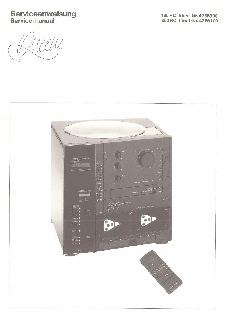
Serviceanweisung 160RC Ident-Nr. 4255800 Service manual 200RC Ident-Nr. 4256100
“tM

Inhaltsverzeichnis
Queens 160 Seite Verdrahtungsplankpl.Gerat. . 2... 2... eee ee eee 8) VerdrahtungsplanCD-Player ............2.00565 @ BlockdiagrammCD-Player ...........222008. ay
Schaltbild(ohneCD-Player)............200005 @) SchaltbildCD-Player . 0. nea we cee eee Ds 8 a3
FAUDIDIALING ks 2 i5 oa eke hae 2 Pa GR BRS © Displayplatine/Schalterplatinen/Phono-Vorverstarker ... . © Klangreglerplatine/Tunerplatine...............4. @ CD=Platiiiew:.; os. 2 oe srk eG Oar ew oe woh es @
AbgleichanweisungTuner..............255. (@)-40 Abgleichanweisung Cassette ............2204. AbgleichanweisungCD-Player .............+4. @ FehlersuchdiagrammCD-Player .........-.-..554-
IC- und Transistor-Blockschaltbilder furCD-Player ..... 4/48) IC- und Transistor-Spannungstabellen furCD-Player ..... 5)
ExplosionsdarstellungGehause.............--. 63 Explosionsdarstellung Cassettenmechanik.......... 64) Explosionsdarstellung Plattenspieler ............. 65) ExplosionsdarstellungCD-Mechanik .............
Ersatzteilliste elektrische Teile(ohneCD) ........... Ersatzteilliste CD-Player (elektrisch u.mechanisch)..... . ErsatzteillisteGehauseteile .. 2... 2... ee eee 62) Ersatzteilliste Cassettenmechanik.............-- 64) ErsatzteillistePlattenspieler. . 2... 2. ee ee eee 64
Bestellhinweise .. 6... es a
Queens 200 Verdrahtungsplankpl.Gerat. . 2.2... ee ee eee 1) VerdrahtungsplanCD-Player .... 0... 0.25.2 eee ay BlockdiagrammCD-Player ... 2... 2.0.0. eee eee a)
SchaltbildReceiver .. 2... 2 ee ee ee @3) Schaltbild Recorder... 2... 2... eee ee ee ee 24) SchaltbildCD-Player ... 2... . 2. ee ee ee ee a3
Hauptplatines. yc .66 8 ao ese Dw ee ee ee Oo 22/25) Displayplatine/Schalterplatinen/Phono-Vorverstarker .... @6 Tunerplatine/Klangreglerplatine............22-5 27) CD=-Platine:: o.0 05 Se seed RAD ee wy ee @
Abgleichanweisung Tuner... . 2... eee eee ee ee 28/29) Abgleichanweisung Cassette ..........2.5.-20 0+ @9) AbgleichanweisungCD-Player .........-22.520505 @ FehlersuchdiagrammCD-Player ..........20005 48)
IC- und Transistor-Blockschaltbilder firCD-Player ..... a4/a5) IC- und Transistor-Spannungstabellen furCD-Player .... . a5)
ExplosionsdarstellungGehause. ............005 67) Explosionsdarstellung Cassettenmechanik.......... ExplosionsdarstellungPlattenspieler ............. 65) Explosionsdarstellung CD-Mechanik .............
Ersatzteilliste elektrische Teile(ohne CD) ........... @0) Ersatzteilliste CD-Player (elektrisch u. mechanisch)...... ErsatzteillisteGehauseteille ..............20-. Ersatzteilliste Cassettenmechanik. .............-. ErsatzteillistePlattenspieler................0.
Bestellhinweise ... 2... 2.2... 20 2 eee eee eee 49)
Subwoofer Schaltbild): = ca a 7 Bao os we ale Bee ee he Netzschalterplatine/LED-Kette-Platine ............ Verstarkerplatine 2.0 se ce © ew oe ee 61) ERSAtZteiliSte® sa: cog sae tae aw as ae te Se ag Kh see wt we ee 61)
Table of contents
Queens 160 Page Wiring diagramwholeunit..............00005 8) WiringdiagramCDplayer............. 02000 - a) BlockdiagramCDplayer .............-.22004 a)
Circuit diagram (withoutCDplayer) .............. @) CircuitdiagramCDplayer............. 00000 a3
Main'iP:C:B: «oa va we ee ew ee ee we 6) Display P.C.B./Switch P.C.B.’s/Pre-amplifierPhono ..... 6) Tone P.C.B/lunerP:G.By sess ose dew s wee eS @) CDIPGiBs 5.6 ue 6 ee ee 4:28 eles Ce eww aw a2
Alignmentproceduretuner ............-.0.4. (8)-0 Alignment procedurecassette............-200- Alignment procedureCDplayer..............0.4. a@ Trouble shooting flowchartCD player .............
IC andtransistor block diagramforCDplayer........ 44/45) IC andtransistor voltage chartsforCDplayer.........
Explodedviewhousing .......... 0.002 ee eae 63 Exploded view cassettemechanism. ............. 64) Explodedview player ..... 2.2... 0 ce eee ee eee 5) ExplodedviewCDmechanism .............+4.
Spare parts list electrical parts (without CD player) ...... Spare parts list CD player (electricalandmechanical) ..... Spare partslisthousingparts ................. 62 Spare parts listcassette mechanism ............. 64) Sparepartslistplayer .. 2... 0... ee eee ee 64)
ImportantiOrOrder: 6 & 6.8. Ve Gee aa ae eae eb
Queens 200 Wiring diagramwholeunit................0-.% @1) Wiring diagramCDplayer.............-...04. 4) BlockdiagramCDplayer ............. 000004 a1)
Circuit diagram Receiver... ........02. 00.000 ee @3 Circuitdiagram Recorder ...........0.00 000 ee 24) CircuitdiagramCDplayer..............2208. 43
MaintPiG:Bs 6 sds a2 whee es Ca BEE OS he eS 22/5) Display P.C.B./Switch P.C.B.’s/Pre-amplifierPhono ..... TunerP.G.B./TONEPIG.B.. 6. 6 4 2 kt alae 8 we oR ws 7) CDIP:GLBs actu 2 ete iach ge eS LR See Be Se LS 42
Alignmentproceduretuner ............-.0004 28/29) Alignment procedurecassette.............000. @9) Alignment procedureCDplayer...............4. a Trouble shooting flowchartCDplayer.............
IC andtransistor block diagramforCDplayer........ a4/45) IC andtransistor voltage chartsforCDplayer ......... (5)
Explodedviewhousing ...........0+0.050805 6) Exploded view cassettemechanism............+.. 68) Explodedviewplayer ...........2. 00004 eae 68) ExplodedviewCDmechanism ............000.%
Spare parts list electrical parts (withoutCD player) ...... 0) Spare parts list CD player (electricalandmechanical) .... . Sparepartslisthousingparts ..............000.% Spare parts listcassette mechanism ............. Sparepartslistplayer ............ 2.000024 ee 64)
Importantfororder... 2... ee ee
Subwoofer Circuitdiagram . ns eee ere eee ee ws Power switch P.C.B./LED powermeterP.C.B. ........ AmplifierP.G.Be ..3. 1. 26 eee ewe wee ee ee eed 61) Spare parntsiist. 6... ¢6%6 64 2.488 wine ea ae BAe oS

Verdrahtungsplan Queens 160 Wiring diagram Queens 160
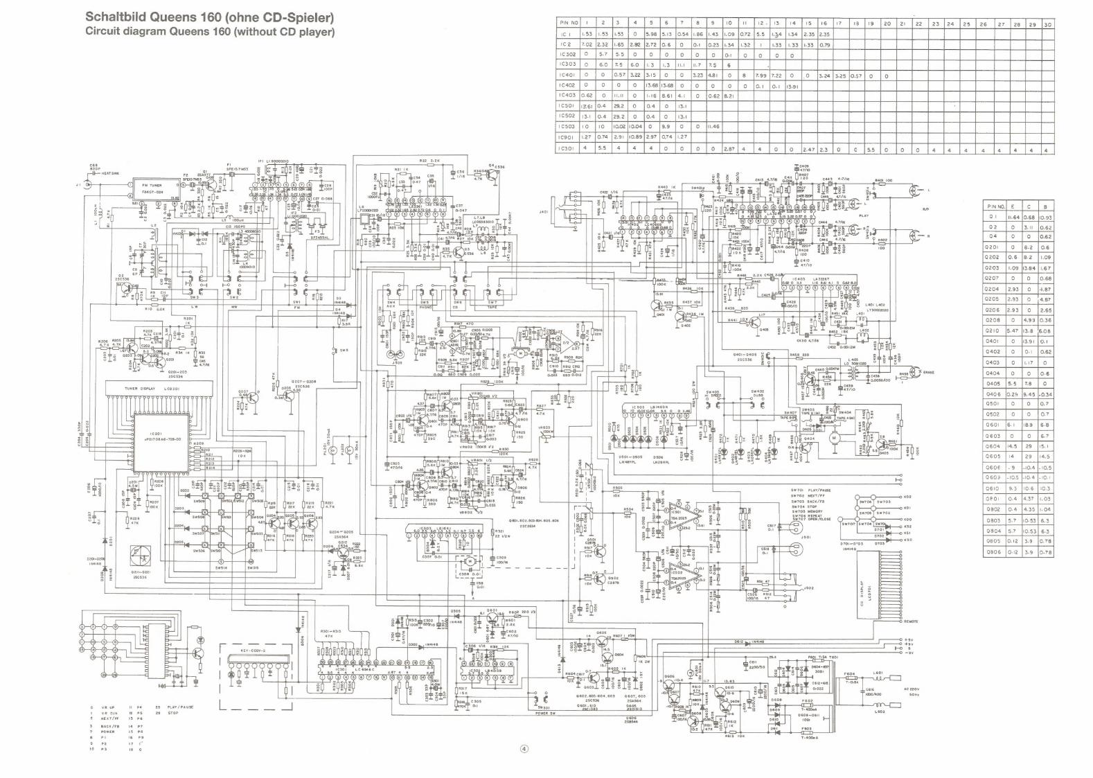
Schaltbild Queens 160 (ohne CD-Spieler) Circuit diagram Queens 160 (without CD player)
eae 2 ee el ee jo |o |szs lee |o [s res |ree]o [io | 2 ee ee
fo [o Jo Jo Jo for Jor fron] | a ee ee ee ee ea] | | { ft 7 | | |
IFI_ L1 30003010 Rie 02K FI
$20P a SFEIO.7MS3 § kg i ays 8 a8 R2l 1K I HEAT SINK F2_2salig7 J — 4 os 3 3 8 . = ca 035 cada’ ARhe scat
SFEIOTHSS 3] 2 g ° A) Spe |c33_ [0-47 0 Bpe't-s = a
ut Q (| Fm Tuner ol) kK): OO ATOO © © @ @ Tes 2 hells vie $s 33 go Q@— + ol MY & 153 T-S3T R 2eee O54 1-86) 100P 0-47 ° ex © 2 SL Gail Pasotese* al] “thes 35 2.38 I 0.72 1,09 143 oer: easy ars zd ~ Wir i 3]
~ © OW OO OMOEA coves © OMA OM OO Bhp iss | 981 (3) a eos fe 31.33 |; 132 | 23 9 z 8 Tse Rp x es 8 ros yi] SSS c2 Ls 3 ms Q 3 s=ts o> 0-01 LF20001020 cae 2 x i = ie 31 1/6 =] aa ” 110002020 ; Ge = ny LS * 100uH 2 canal , “Le cIS_150PS Sis 28 —RZ g
x 3400080) IS Trl U8 Tse = & — ao =e € |] 4 SFZ455HL C446 4.7/6 R402 S zUe| » = —
8fjx o38 100 zU8 Iss
ch 410 T I 47/10
2.2K C426 2. _ a, 0 1403 LA3226T
L] iD = lo.e2 0 tll 116 8.61 4.1 0 0.62 8.21 R436_10K ¥ 1®OO@O® © O © O,We
— - slTets
Ee ycs | el | me
3 ot. c428 Sie 2 bay INaI48, e" _ = | | fede F[]g § L401 raoz
04 3 CB im |e! = <= T= LT30002020 1N4148 Rd ‘401 (> R438 1M [|] R451 18K L401
° RIT 3 hs = K) aio ZI 3.9K (3 0.402 oS gers g
os «68 7 SIR = « 1 =
C430 4.716 m 8
432 0.0012M = sws a aaoi~aaos 3p R458 _220 Bie te6 > ascs3e = S L403 ST8 Tee
8 a 2 Lo 30011020 = |6
i HIE — pat Q201~203 x 0.012 680 C909 0.022 Cs i 2SC536 i = 0.0056A00 2 Q207~ Q208 31] R829 _ 120K
TUNER DISPLAY LCD 201 87 0208 ‘ise . sw403 sw4o2 Co ; 809 Reo} HI SPEED use ° oN ooo oR oM on oH okoNemeReMeRoRoRene) > oO °
1¢503 LBI403N a a & lO _10 10.0210.04 9.9 Sw407 x ———T [ree 2
co)
“ 8 3
¢ a] 6 rs oly 2 = 2 > 8 sie fy~ 3] 3] 8 uPDI708 AG -728-00 2 a = « ZEUS os o7 E 2 oO6 on x
oLsé 3 Fy Snes Z : se® 33 aS zis a ooy se ai 3 DS50!~ D505 $8 38 zUs
- mene LN48YPL es eS 7 = 6K 2 ‘L470A6 § _S 435 3
ee 2 (] csos xl lalg c804 ue T AO $7 els
3 3 F KK )osoz si '712 mS08 SW70!1 PLAY/PAUSE 8 a J csdB{o.4 ae 10K 8 SW702 NEXT/FF © KD2 Pa bn [es 470P yR806 | o= SW703 BACK/FB 3 Rz2i 8 2 390 = sls SW704 STOP O O © KD! ba se oor We c N ors SW705 MEMORY 7 WR srs 1] 5 SW706 REPEAT sl lols 10K Ny 8 SW707 OPEN/CLOSE () O O Oo KDO si= Q80!,802.803-804.805. 806 OTS 3 =] =
- 1303 Lei64) asCees lane Sia 6 ents 3 2 L__y_g xsi 0204 0205 6.0 75 "6.0 1.3 1-3 ei 7 75 6 A) R32 Jee als aTOn S
5 asasea POO ysves | 8 sso 0 Kso 9805 |o.12 |3.9 |o.78 : H | D701~D703 0703 4
| = rt INdI48 : | 26 cS) Q806 0.12 |3.9 |0.78
Pras bee aL 0201~D205, 100/16 3] e138 INdI48. i Sa eee Sls] 2 By =
os is 8 3 o 2 Q2itnQ22i 8 a | =e | S = 2SC536 oO g- RSN47 ° i |
= g — ° é6 ee u = Lo. it om o J 2 a 2
=n, e526) «R512 So bos | sf O06 47 7 | 7 3 = eo ES 3-/ ° ra
3 O REMOTE 2 8 R301 ~R313 3
+5v 3 D6I2 p INaI48, BS aey — —_— fo ¢
Oo -9v KEY-Cosv-2 a Hell F6Q!_T-5A T6O! _ Sees HO 2OHOH®@ OO000000| =8 C301 LC 6546C = F604 Leo! ® (] = (] I 4.55 4 4 4 2.87 4 4 2.4 0 Y - | VOODOO OOOO OU GHH = eae ae —
° = 2 Usushl all [] 3 3 0-022 Ac 220v LI | E 3 sons 8 @602.603-604.609 9607, 608 S a 2Sc536 2Sa564 F602
[I 9601, 610 ° VR UP PS 28 = PLAY / PAUSE i 2s 8 i603 ' VR DUN 2 PSs 29 STOP POWER Sw sae page soe! zi NEXT/FF 13 P6
2SB544
3 BACK/FB 14-P7 7 POWER 15 PB RaIs 10K TaGaak 8 PI 16 PS 2 pez i
Ps is 0 @ 3
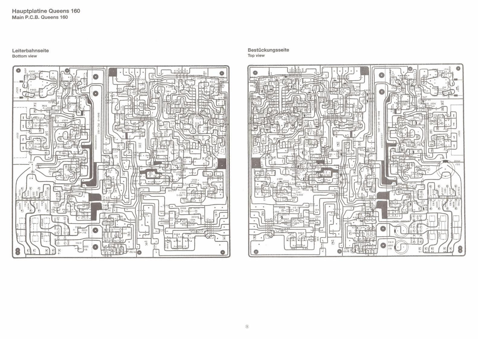
Bestiickungsseite Top view
Hauptplatine Queens 160 Main P.C.B. Queens 160
Leiterbahnseite Bottom view
Es
b a)
3 :
: 3s
iO
q
U Ces
¥ Q0
yo
6
ta
re
u/(P)
= (
A) JOG
a ®
i
‘ il
ps
Ou
4 “J
oT)
\ au
pied
3
- =e)
)
1%
3
Ay
q wenni)-a\
Ae
i oe
cae
i
mai),
: .
CO
arouse
71
. 4
Ws =n
[|
an Ue
NY f
r<eun 2
0
1 th
mae 1a
1% i Q
;
Hor}
Us D uy 4 im
{ 3 q
M -
= -N
el ONL
i 39
SObp = \
ed
>
xpd
«Bis BO
4 ae
S =o
f @
<4 8
sj dOde
, oF
5 0
D A
10. |
Lh
4 ;
: OO)
Ae OQ
e EY
5 d
f =
Dt
= ie
: :
a
bard p> > IC d STE ay eh (POR br lal
,
3 :
=
O Sf
fF G
dD Sik
C R
i t
s a’
Oo
: °
q og
: rad)
n |
on
x 9°75
P BC)
(Ds aenaE
PS
¢ ON
ON
doko :
0) EK)
AP
A) ys
S., _OHD~
a8
P os,
js
Dlg doar
YP
=
Any
= Ris
% J
Gye :
BY
i>
jf =
: OT
’ ;
LOLS
FA) ws
\ Cl_>
| *
Pat) ©
das dg
ur

Displayplatine/Schalterplatinen CD-Tape, Queens 160 Display P.C.B./Switch P.C.B.’s CD-Tape, Queens 160
Bestiickungsseite Top view
\ ear
EP REEr eer Ppa
To saan 4 PPK |
ies 1 ll ANN
eee (Qu
fe
fie CFT ON
ne
iS Smee i asa), w AG (aa seo 6:
we | Gamer
| i
2 i ee eS ee Os he 01
5 R3O
s (5 Bpciomeiic, aa SEL)
Leiterbahnseite Bottom view
a S52 = Vi ee Erererer ]
iano ee
B eye as ast! —— “
Styne ree
ereae Pees Bite)
8 r 5| rpki , host 1G caee 1. =
te “hd . 108
' ae EE 3); 2 ares fd als 7
: ; an Ls | a
Phono-Vorverstarkerplatine Pre-amplifier P.C.B. phono
Bestiickungsseite Top view
Leiterbahnseite
Bottom view

Klangreglerplatine Queens 160 Tunerplatine Queens 160 Tone P.C.B. Queens 160 Tuner P.C.B. Queens 160
Bestiickungsseite Top view
Bestuckungsseite Top view
vr oO I “A
oO _
> oc os © =] o
Leiterbahnseite Bottom view
Leiterbahnseite
Bottom view
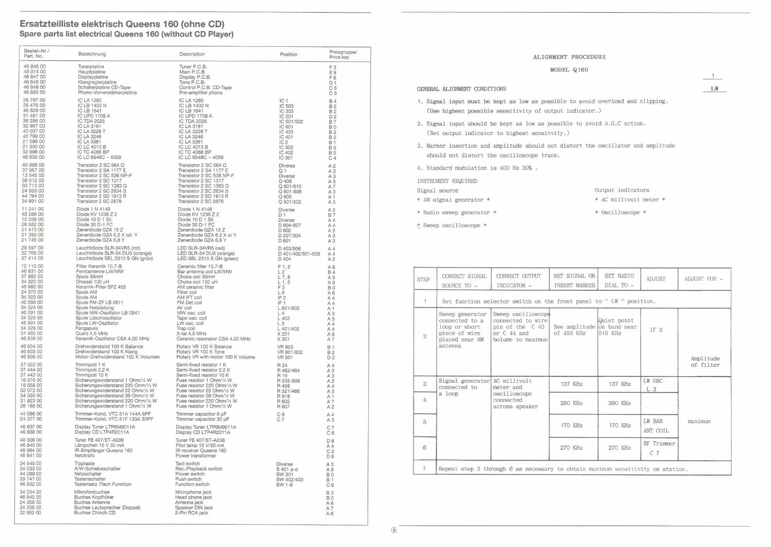
Ersatzteilliste elektrisch Queens 160 (ohne CD) Spare parts list electrical Queens 160 (without CD Player)
Bestell-Nr./ Part. No.
46 846 00 48 014 00 46 847 00 46 848 00 46 849 00 46 850 00
26 797 00 26 476 00 46 829 00 31 481 00 38 286 00 32 997 00 40 037 00 40 799 00 21 596 00 21 330 00 32 998 00 46 830 00
45 988 00 37 957 00 13 545 00 08 012 00 03 713 00 24 533 00 44 764 00 34 691 00
11 241 00 40 288 00 12 039 00 26 552 00 21 413 00 21 350 00 21 745 00
29 597 00 32 768 00 37 414 00
12 110 00 46 831 00 37 882 00 34 320 00 45 992 00 24 372 00 34 322 00 40 293 00 34 324 00 40 291 00 34 325 00 45 991 00 34 326 00 31 482 00 46 839 00
46 834 00 46 835 00 46 836 00
37 022 00 37 444 00 37 443 00 18 576 00 18 558 00 32 072 00 34 335 00 31 823 00 26 168 00
44 086 00 24 377 00
46 837 00 46 838 00
40 306 00 46 840 00 46 994 00 46 841 00
34 545 00 34 033 00 44 089 00 29 747 00 46 832 00
34 034 00 46 842 00 24 358 00 34 338 00 32 952 00
Bezeichnung
Tunerplatine Hauptplatine Displayplatine Klangreglerplatine Schalterplatine CD-Tape Phono-Vorverstarkerplatine
IC LA 1260 IC LB 1403 N IC LB 1641 IC UPD 1708 A IC TDA 2025 IC LA 3161 IC LA 3226 T IC LA 3246 IC LA 3361 IC LC 4013 B IC TC 4066 BP IC LC 6546C — 4059
Transistor 2 SC 564 Q Transistor 2SA 1177 E Transistor 2 SC 536 NP-F Transistor 2 SC 1317 Transistor 2 SC 1383 Q Transistor 2 SC 2634 S Transistor 2 SD 1913 R Transistor 2 SC 2878
Diode 1 N 4148 Diode KV 1236 Z 2 Diode 10 D 1 Sil. Diode 30 D-1 FC Zenerdiode GZA 15 Z Zenerdiode GZA 6,2 X od. Y Zenerdiode GZA 6,8 Y
Leuchtdiode SLR-34VR5 (rot) Leuchtdiode SLR-34 DU5 (orange) Leuchtdiode SEL 2310 S GN (griin)
Filter Keramik 10.7-B Ferritantenne LW/MW Spule 39mH Drossel 100 uwH Keramik-Filter SFZ 455 Spule AM Spule AM Spule FM-ZF LB 0511 Spule Netzleitung Spule MW-Oszillator LB 0541 Spule Léschoszillator Spule LW-Oszillator Fangspule Quarz 4,5 MHz Keramik-Oszillator CSA 4,00 MHz
Drehwiderstand 100 K Balance Drehwiderstand 100 K Klang Motor-Drehwiderstand 100 K Volumen
Trimmpoti 1K Trimmpoti 2,2 K Trimmpoti 10 K Sicherungswiderstand 1 Ohm//4 W Sicherungswiderstand 220 Ohm//% W Sicherungswiderstand 22 Ohm/‘2 W Sicherungswiderstand 39 Ohm/'2 W Sicherungswiderstand 220 Ohm/‘2 W Sicherungswiderstand 1 Ohm/2 W
Trimmer-Kond. VTC 51A 144A 6PF Trimmer-Kond. VTC 51F 133A 30PF
Display Tuner LTP6M9011A Display CD LTP4R2011A
Tuner FE 407/ET-A036 Lampchen 15 V 30 mA IR-Empfanger Queens 160 Netztrafo
Tipptaste A/W-Schiebeschalter Netzschalter Tastenschalter Tastensatz 7fach Funktion
Mikrofonbuchse Buchse Kopfhérer Buchse Antenne Buchse Lautsprecher (Doppel) Buchse Chinch CD
Description Position
Tuner P.C.B. Main P.C.B. Display P.C.B. Tone P.C.B. Control P.C.B. CD-Tape Pre-amplifier phono
IC LA 1260 IC 1 IC LB 1403 N IC 503 IC LB 1641 IC 303 IC UPD 1708 A IC 201 IC TDA 2025 IC 501/502 IC LA 3161 IC 901 IC LA 3226 T IC 403 IC LA 3246 IC 401 IC LA 3361 IC 2 IC LC 4013 B IC 302 IC TC 4066 BP IC 402 IC LC 6546C — 4059 IC 301
Transistor 2 SC 564 Q Diverse Transistor 2 SA 1177 E Q1 Transistor 2 SC 536 NP-F Diverse Transistor 2 SC 1317 Q 406 Transistor 2 SC 1383 Q Q 601/610 Transistor 2 SC 2634 S Q 801-806 Transistor 2 SD 1913 R Q 605 Transistor 2 SC 2878 Q 501/502
Diode 1 N 4148 Diverse Diode KV 1236 Z 2 D1 Diode 10 D 1 Sil. Diverse Diode 30 D-1 FC D 604-607 Zenerdiode GZA 15 Z D 602 Zenerdiode GZA 6.2 X or Y D 207/304 Zenerdiode GZA 6.8 Y D601
LED SLR-34VR8 (red) D 403/506 LED SLR-34 DU5 (orange) LED SEL 2310 S GN (green)
Ceramic filter 10.7-B Bar antenna coil LW/MW Choke coil 39mH Choke coil 100 wH AM ceramic filter Filter coil AM IFT coil FM Det coil Air coil MW osc. coil Tape osc. coil LW osc. coil Trap coil X-tal 4.5 MHz Ceramic resonator CSA 4.00 MHz
Rotary VR 100 K Balance Rotary VR 100 K Tone Rotary VR with motor 100 K Volume
Semi-fixed resistor 1 K Semi-fixed resistor 2.2 K Semi-fixed resistor 10 K Fuse resistor 1 Ohm/% W Fuse resistor 220 Ohm/%4 W Fuse resistor 22 Ohm/%2 W Fuse resistor 39 Ohm/'2 W Fuse resistor 220 Ohm/12 W Fuse resistor 1 Ohm/12 W
Trimmer capacitor 6 pF Trimmer capacitor 30 pF
Display Tuner LTP6M9011A Display CD LTP4R2011A
Tuner FE 407/ET-A036 Pilot lamp 15 V/30 mA IR receiver Queens 160 Power transformer
Tact switch Rec./Playback switch Power switch Push switch Function switch
Microphone jack Head phone jack Antenna jack Speaker DIN jack 2-Pin RCA jack
D 401/402/501-505 D 404
F1,2 L2 L7,8 L1,5 F3 L6 IF 2 IF 1 L 601/602 L4 L 403 L3 L 401/402 X 201 X 301
VR 803 VR 801/802 VR 501
R 24 R 462/464 R19 R 505-508 R 458 R 321/466 R918 R 602 R 607
cg C7
Diverse S 401 a-d SW 301 SW 402/403 SW 1-8
Preisgruppe/ Price key
F3 E9 F8
ODDWDWDDDHDOWWDW ONO ROMN-|ANMNONNNYNA OM
ALIGNMENT. PROCEDURE
GENERAL ALIGNMENT CONDITIONS
MODEL Q160
LW
1. Signal input must be kept as low as possible to avoid overload and clipping.
(Use highest possible sensitivity of output indicator.)
2. Signal input should be kept as low as possible to avoid A.G.C action.
(Set output indicator to highest sensitvity.)
3. Marker insertion and amplitude should not distort the oscillator and amplitude
should not distort the oscilloscope trace.
4. Standard modulation is 400 Hz 30% .
INSTRUMENT REQUIRED
Signal source
* AM Signal generator *
* Radio sweep generator *
* Sweep oscilloscope *
7
CONNECT SIGNAL | CONNECT OUTPUT
SOURCE TO - INDICATOR -
Output indicators
* AC millivolt meter *
* Oscilloscope *
SET RADIO
DIAL TO -
SET SIGNAL OR
INSERT MARKER ADJUST ADJUST FOR -
Set function selector switch on the front panel to "' LW " position.
Sweep generator connected to a
loop or short
piece of wire placed near AM
antenna
Signal generator connected to
Sweep oscilloscopé¢ connected to wire
pin of the C 43 or C 44 and
bolume to maximun
AC millivolt
meter and
oscilloscope
connected
across speaker
Quiet point
See amplitude jon band near 515 KHz
Amplitude of filter
137 KHz 137 KHz | LW Ose L 3
LW BAR maximum 170 KHz 170 KHz
ANT COIL
RF Trimmer 270 KHz 270 KHz F
Cc
Repeat step 3 through 6 as necessary to obtain maximum sensitivity on station.

ALIGNMENT PROCEDURE ALIGNMENT PROCEDURE
MODEL Q160 MODEL Q160
3 =
GENERAL ALIGNMENT CONDITIONS MW GENERAL ALIGNMENT CONDITION _ FM
1. Signal input must be kept as low as possible to avaid overload and clipping. 1. Signal input must be kept as low as possible to avoid ocerload clipping.
(Use highest possible sensitivity of output -indicator.) (Use highest possitivity of output indicator.)
2. Signal input should be kept as low as possible to avoid A:G.C. action. 2. Makers must be accurate (crystal controlled or calibrated). The 10.7 MHz marker
(Set output indicator to highest sensitivity.) used in each section of the FM alignment must be the same.
3. Signal input should be kept as low as possible to avoid A.G.C. action. 3. Maker insertion and amplitude should i i i Fags Peed plitude should not distort the oscillator and amplitude (Set output indicator to highest sensitivity.)
should not distort th il ‘ i i € oscilloscope trace 4. FM signal generator RF output frequency must be monitoring.
4. Standard modulation is 400 Hz. 5. Standard modulation is 1 KHz ( 40 KHz)
INSTRUMENTS REQUIRED INSTRUMENTS REQUIRED
Signal source Output indicators Signal sources Output indicators * AM signal generator * * AC millivolt meter * * FM signal generator * * AC millivolt meter *
* Radio sweep generator * * Oscilloscope * * Radio sweep generator * Cael tiescene © * Sweep oscilloscope * * 114 KHz signal generator *
* Sweep oscilloscope * * Frequency counter *
SOURCE TO - INDICATOR - INSERT MARKER | DIAL TO -
CONNECT SIGNAL | CONNECT OUTPUT | SET SIGNAL OR SET RADIO ADJUST ADJUST FOR —
SOURCE TO - INDICATOR TO — | INSERT MARKER DIAL TO CONNECT SIGNAL | CONNECT OUTPUT SET SIGNAL OR | SET RADIO ADJUST ADJUST FOR —
Set function selector switch on the front panel to '' FM " position.
Radio sweep Oscilloscope Quiet Straightness S + + tw ai + + et function selector switch on the front panel to '" MW "' position. connected to seale and symmetry
wire pin of the pointer of ' S " curve
FM front ent C 43 of C 44 on band with 10.7 MHz
tuner pin 3 and volume VR makerd at zero
to maximum crossover
Sweep generator |Sweep oscilloscope
connected to a |connected to wire | See amplitude | Quiet point
loop or short |pin of the C 43 of 455 KHz on band near piece of wire |of C 44 and 513 KHz placed near AM |volume to mzximum
antenna
Amp1 tude oft filter
Signal generat—|AC millivolt or connected to a loop i
1620 KHz 1620 KHz —
AM BAR . 600 KHz 600 KHz ae Gon: TED
RF Trimmer
1400 KHz 1400 KHz as
Repeat step 3 through 6 necessary to obtain maximum sensitivity on station.

ALIGNMENT PROCEDURE
MODEL Q160 4
MPX
GENERAL ALIGNMENT CONDITION
1. Adjust FM signal generator output to ImV (60dB) with MPX modulation 1 KHz
Deviation = 33.75 KHz Pilot = 6 KHz
INSTRUMENTS REQUIRED
Signal source Output indicator
* FM signal generator * * Frequency counter *
* Stereo signal generator * * AC millivolt meter *
* Oscilloscope *
| 1 | set function selector switch on the front panel to '" FM STEREO " Position.
eee CONNECT SIGNAL] CCNNECT OUTPUT SET SIGNAL SET RADIO ADJUST ADJUST FOR —
INDICATOR TO _-
modulation off, pilot signal off too
generator
connected to
FM aerial
19.00 KHz
+ / - 50 Hz [PX test point 98 MHz R- 19
Abgleichanweisung Cassette Queens 160 Alignment procedure cassette Queens 160
TAPE POSITION TEST TAPE peered Recorderstellung Testcassette MeBgerat
1. Head azimuth/A/W-Kopf-Einstellung
MTT-114.N V.T.V.M | PLAYBACK 10 kHz AC-Millivoltmeter
2. Tape speed/Geschwindigkeit
ADJUSTMENT LOCATION
Abgleichpunkt
MEASURING SIGNAL
MeBsignal
TESTPOINT MeBpunkt
OUT L CH OUT R CH AZIMUTH SCREW NF-max.
PLAYBACK MTT- 111.N FREQUENCY R 464 3000 Hz
PLAYBACK MTT-111 N Frequenz- at LAbet te ea OUT UR CH R 462 4800 Hz
3. Oscillator coil frequency/Oszillatorfrequenz
FREQUENCY COUNTER
Frequenzzahler
ERASE HEAD Loschkopf
85 kHz +/-5 kHz
AC-212 RECORD aot L 403
Léschspannung: ca. 100 Vss
Vormagnetisierung: ca. 34 Vss

Verdrahtungsplan CD-Player Queens 160/Queens 200 Blockdiagramm CD-Player Queens 160/Queens 200 Wiring diagram CD player Queens 160/Queens 200 Block diagram CD player Queens 160/Queens 200
COMPACT DISC
ADING MOTOR
DRIVE DRIVE 7
CXA1082 CXA1081 SERVO SIGNAL RE AMP PROCESSOR
CXD/1135Q DIGITAL SIGNAL a PROCESSOR 2048 x 8-BIT DIGITAL FILTER ae
CXP-5016 SYSTEM CONTROL
DISPLAY AND KEY |
(1); (2)
P.1.C. SW LOADING MOTOR
LC7880 D/A CONVERTER
DISC MOTOR
= 2)
Z 8 & E a x AUDIO (5) s = CIRCUITRY
(4) Qo (1) (3)
my AUDIO OUT
Y © L R

Schaltbild IC-Zusatzplatine SP001 CPC-S2101 zu CD-Player Cc
CD-Platine CD P.C.B. Sub P.C.B. SP001 CPC-S2101 for CD player ircuit diagram
Bestickungsseite Top view
LRCK
WOCK
DAI6
DAIS
XTACO
XTALI
—— OO CON
{ x24)
+5V
O nC
SPDL-
SPDLO
FOK
O MIRR
et Tad
DFCT
Te
FE
i) VIC
FEO
Fem
SRCH
O +SV
TAO
O TaA~
FEEOC
FEEDD
GND
CXA1082
4 $N3S}
Fsw O
MDS
MON O
MOP O
EFM O
ASY O
LOocKO
vco O
3.5V O
PbO
BW GND
CLK
XLT
DATAO
XRSTO
CNINO
SENSO
MUTGO
CRCFO
EXCKO
suB00
scorOo
spso0o0
sackoO
OTOXO
GFs
o—
|}o
va
«Moti
a4
&
Eo
VUWee-diq=Ee>
OAxX&>U
Oo}
L>0]
wwa
COS
HNVO
OM
ent
tus
a2a0axxu+Z20Mw=
! aruwswwM+Feu iL
QD
DOO
OQ
OOOOOOD
“
ftr20u~oroxrx<
BNZOLE>+VO™O
AXKERN—ZREUUMONUEN
nocar.noaszZzioIaeZzwdsexD.UMaeu
LES lw
>M
Oo NVVKOAKVMNEUWNNNMNAWY
sf pasonnsanicatasanepecoscsananaton
O-
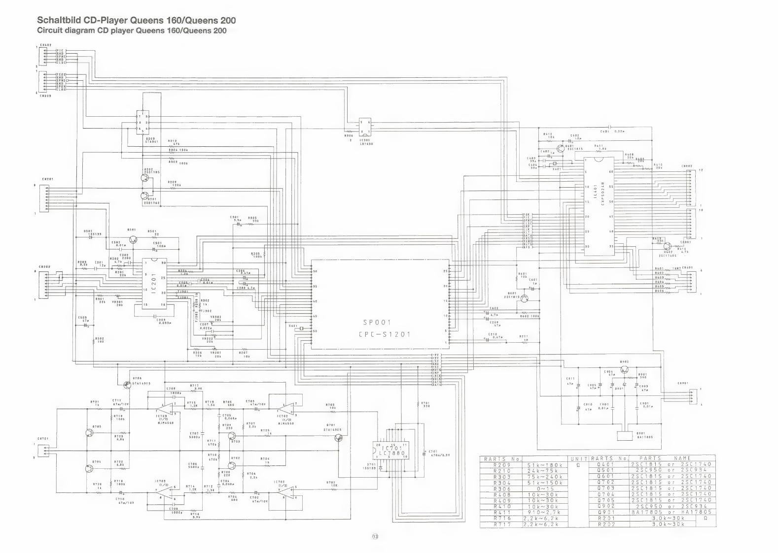
Schaltbild CD-Player Queens 160/Queens 200 Circuit diagram CD player Queens 160/Queens 200
1 Nbo2 PIC GND OPNC GND CLSC
5 1
FEED! pup 'SPND —=] GND t OPEN) —- Los)
6 cN203
7 3
8 2 el ee Ga eas 4h
5 — ebie ChOS 0.02 7 C402
0203 gE 10 STAS&1 ator + +
0401
R304 150k tS C1618
R303 1 go, pew 410 ait CN802
0202 12 2801185 SY)
CN201 (> a R209
120k
CXPSO24H
w
a ak ak n °
w
te S78 R602 100k
sPO001 "6209 |
CPCs 1 201 Pee ee R211
r 0902
- + > ne
ce R901
0706 cont 390 <0 aaleiiial 47h x £908 J ees CN9O1
47s
~ — —— ee Srastov 1. : aes - | Oey. ee eos . —----+— ae ite 0.018 =
R719 1¢703 3 ii
100k (172) .
NJIM4&560 4 4 _|
Q705 a DTAI4S3ES |
CN aH ‘a CA lil ATE 704 6.8k ty)
20 is VE
[= af t T D) yee a C701
oros | a2 a << RARTS No, UNIT[RARTS No] PARTS NAME =i
to D704 TTT R209 Sik~180k Q a401 28C1815 or 2SC1740
o ee R210 24K=T5 k 0501 7SC950 or 25C934 TT R303 75k~240k a601 28C1815 or 28C1740
nao 3108 ate R703 R304 5 1k~150k a7 02 PSC 1615 of 25C1740 ww R306 O~15 a703 2801815 or 28C1740
R408 TOk~30k a704 25C1815 or 2S5C1740 17a/10V R409 TOk~30k a7 05 25C1815 or 2S8C1740
R410 1Ok~30k a9 02 28C950 or 2SC934 | R411 910~2.7k 0901 BA17805 or HA17805
a 2.2k~6.2k R201 3,0k~30k q R717 7,.2k~6.2k R202 3,0k~30k

IC- und Transistor-Blockschaltbilder fir CD-Player IC and transistor block diagrams for CD player lana oak the I/O with bit unit)
Aa v v Q203 STA341M re O20
XTALO VLC3
Za 1SS133 D501, 701 EXTAL © c STA341M Q203 RST o. ©VLC1
wpe o COMO
INT1 © OCOM1
PYoo ©COM2 2
Bye 0 COM3 ‘
. INT2/PY2 O—+(8) SEGO Register
Ec/pY3 o—~() seci © Jerr nrnrrHe-—
28D1762 Q201 SC/PXO O SEG2
Zz HZ6BIRE = D901 aeBiies; (Q202 SOB/PX1 0 0 SEG3
7 SOA/PX2 © SEG4 SI/PX3 © SEG5 re
0 EGS fe) oad an = Date memory PD1 O==! SEG7 ne
PD2 0 SEG8 ae
PD3 0 o SEG9 N
PCO oO 0 SEG10
PC1.0 0 SEG11 2SA950 —Q501, 902 BG osece0—lt(<i‘(<(<‘il!];(S:*”*C«éCdirR Re eee enn
DTA143ES —_Q701, 706 i tb, PC3 © 0 SEG13
23 E PBO SEG14
PBI SEG15
PB20 © SEG16/PFO
PBS © SEG17/PF1
PAO © SEG18/PF2
PAI © SEG19/PF3
BA17805 901 eee O;SeG20/PEP 28C1740 —Q401, 402, 601, 702 PA3O © SEG21/PE1
Q703, 704, 705 nes emacs LCD
~c® Vsso © SEG23/PE3 controller
VL driver VLC1 .
1C401 CXP5024H Vice
VLC3
IC 701 LC7880
SEG16 SEGO COMO
SEG23 SEG15 COM3
ee (Combined use Li 10) E
with port E and port F)
TIMING CONTROL
R- STRING DAC
IC 702, 703
ol LEVEL SHIFT BA4560 DAC
OUTPUT (1)
_ be A es (4)
(8) Vee
CH2 LATCH OUTPUT 7)
Ar INV INPUT
)
NON -INV INPUT
NON-INV INPUT
(Enables to specify (Mask option in combination
the I/O with port unit) with segment output) a a
[ai [at tat 44?
| o Vic2
Program counter
(12) ALU
| Accumulator | :
Ne Timer/counter (8)
Serial I/O (8) .
Interruption control
Program
memory 4096 x B bit
Command control
EXTAL
XTAL
PX3/. PX1/.—- PY3/_ PY1 S1 SOB EC
PX2/ PX0/ PY2/ PYO SOA SC INT2
(Combined use with serial |/O)
1C401 CXP5024H
IC 702, 703 BA4560
output (1) (8) Vee
Inv INPUT (2) (7) output
NON-INV INPUT (3) (6) INV INPUT
vee (4) (5) NON-INV INPUT

IC- und Transistor-Spannungstabellen fur CD-Player
IC and transistor voltage charts for CD player
DC
| 0401
| 0705
IC 201 CXA1081
REFERENCE REFERENCE
FOK COMPARATOR
- L___> ae J FOK AMP,
Pats comparator LI @) 1c20! - EFM CXAIO081
~ AUTO AUTO ASYMMETRY
RF SUMMING ASYMMETRY BUFFER AM CONTROL
‘AMP j <I 6)
as “aMe q (25) 0 GND
Ga)
ASY
RF |-V AMP (
cB
cP
RF 1-V AMP ( ie i O AMP MIRR
rN Fi-V AMP oO —
OEFECT
OEFECT DEFECT = BOTTOM HOLD COMPARATOR
TE
> TRACKING ERROR AMP
CENTER VOLTAGE BUFFER VEE
ccl
| 5.0] 5.0 | 5...0
Vour: Yours 1C301 Pin No.| 31] 32{ 33] 34] 35| 36, ai oc | 0.0] 0.0] 5.0] 5.0| 5.0| 5.0]
Nee LB1630 [Pin No.| 46] 47] 48] 49] 50] 1)
ct Vin 1 (1) (8) Vout 1
7 GND() (7) Vee
Vcont (3) (6) NC
vin 2 (4) (5) Vout 2 |Pin No. | 16{ 17] 18] 19] 20) [| oc f 0.07 0.0] 0.0} :
1C301 LB1630

Explosionsdarstellung CD-Mechanik Queens 160/Queens 200 Exploded view CD mechanism
Explo-Index: CD
Ersatzteilliste CD-Player Spare parts list CD player
ies Bezeichnung Description Position beter pel
Elektrische Teile/Electrical parts
46 819 00 CD-Spieler kpl. CD player assembly A22 G2
46 876 00 CD-Platine CD P.C.B. CM 60 FQ 46 877 00 IC-Zusatzplatine JO19 IC P.C.B. JO19 J019 E5
46 747 00 IC CXA 1081 S RF Amplifier IC CXA 1081 S RF Amplifier IC 201 B4 46 748 00 IC LB 1630 Motor Driver IC LB 1630 motor driver IC 301 B3 46 878 00 IC CXP 5024 H-076S IC CXP 5024H-076S IC 401 D5 46 501 00 _IC LC 7880 = LC 7881 IC LC 7880 = LC 7881 IC 701 BQ 40 765 00 IC BA 4560 o. UPC 4560 IC BA 4560 0. UPC 4560 IC 702/703 A6
40 767 00 Transistor 2 SD 1762 E Transistor 2 SD 1762 E Q 201 AZ 40 766 00 Transistor 2 SB 1185 E Transistor 2 SB 1185 E Q 202 A8 40 768 00 Transistor STA 341 M Transistor STA 341 M Q 203 B4 34 692 00 Transistor 2 SC 1740 Transistor 2 SC 1740 Diverse A2 46 752 00 Transistor 2 SA 950 Y Transistor 2 SA 950 Y Q 501/902 A5 40 368 00 Transistor DTA 143 XS Transistor DTA 143 XS Q 701/706 A2 46 751 00 Transistor HA 17805 Transistor HA 17805 Q 901 A8&
24 750 00 Diode 1 SS 133 Diode 1 SS 133 D 501/701 A2 46 879 00 Zenerdiode HZ 6B1 RE Zenerdiode HZ 6B1 RE D901 A3
29 622 00 Trimmpoti 20 kOhm Semi-fixed resistor 20 kKOhm Diverse A3
40 769 00 Quarz XTP0334-16934K015 16,9344 MHz Crystal XTP0334-16934K015 16.9344 MHz xX 601 B2 46 839 00 Keramik-Oszillator CSA 4,00 MHz Ceramic resonator CSA 4.00 MHz X 401 A7
Mechanische Teile/Mechanical parts
46 755 00 Schlitten CD-Platte Tray DM 1 B4 46 756 00 Auflagebtigel CD-Platte Lifter DM 2 BO 46 869 00 Feder Auflagebtigel Spring lifter DM 4 A2 46 757 00 Zentrierscheibe oben Disk cramper DM 8 A3 46 758 00 Kurvenzahnrad Lademechanik Drive gear DM 11 AQ 34 315 00 Sicherungsring fir Kurvenzahnrad E-Ring spring DM 15 AO 46 759 00 Schaltkontakt LSC-1223-31 Leaf SW DM 17 AQ 44 132 00 Mikroschalter MSW L 541 T Leaf switch MSW L 541 T DM 18 A4 46 870 00 Gewindestange Laserschlitten Lead screw laser DM 22 Bi 44 121 00 Pulley Gewindestange Pulley feed DM 23 A2 46 871 00 Fuhrungsrolle Gewindestange S-rack lead screw DM 25 A3 46 760 00 Laserabtaster kpl. Laser pick up DM 26 F1 44 116 00 Riemen Lasermotor Belt laser motor DM 29 A3 44 124 00 Gleitstange Guide shaft DM 30 A4 46 761 00 Motor Antrieb CD-Platte Disk motor DM 34 co 46 762 00 Antriebsteller Disk table DM 37 Bo 46 872 00 Feder Antriebsteller Locater spring DM 38 Al 46 763 00 Zentrierscheibe unten Locater DM 39 A3 46 873 00 Kappe Zentrierscheibe Locater cup DM 40 A3 44 11500 Motorpulley Laser Motorpulley laser DM 41 Al 44 11700 Motor Laser Motor laser DM 42 B6 46 874 00 Gleithebel Kippmechanik Slide lever cam DM 48 A7 46 875 00 Druckhebel Kippmechanik Lever push DM 49 A5 46 764 00 Zwischenrad/Lademechanik Idle gear C DM 52 A3 46 765 00 Riemen Lademotor Belt DM 53 A4 40 752 00 Motor Schlitten Motor tray DM 54 BQ 46 766 00 Pully Lademotor Motor pulley DM 55 A2

Abgleichanweisung CD-Spieler
Bendtigte MeBgerate: Frequenzzahler Test-CD Oszilloskop
VCO-Frequenzabgleich
Dieser Abgleich kann ohne CD-Platte durchgefiihrt werden.
1. Frequenzzahler an Testpunkt VCO und Masse anschlieBen. 2. Pin 6 der IC-Zusatzplatine mit Masse TJ 901 verbinden. 3. Gerat einschalten. 4. Mit Poti VR auf der IC-Zusatzplatine Frequenz auf 4,3218
+0,01 MHz abgleichen.
5. KurzschluBbriicke an Pin 6 der !C-Zusatzplatine wieder ent- fernen.
IC-Zusatzplatine Sub PCB
EF-Balance und Focus-Offset-Abgleich
1. CD-Platte einlegen und »PLAY«-Taste driicken. 2. Oszilloskop an Testpunkt TJ 203 und Masse TJ 901 an-
schlieBen. 3. HF-Signal mit VR 201 und VR 301 auf Maximum abgleichen.
Fokus-Servo-Verstarkung
(Einstellung von Fokus- und Spurfuhrungsverstarkung) Fur genauen Abgleich ist ein Servo-Analysator erforderlich. Jedoch besteht bei Normalbetrieb auch dann keine Schwierig- keit, wenn eine geringe Abweichung von den zulassigen Werten auftritt, da die Verstarkung in einem gewissen Bereich variieren kann. Deswegen sollte dieser Abgleich nicht ausgefiihrt werden. Mit der Fokus- und Spurflhrungsverstarkung werden Nachfuhr- eigenschaften des Abtasters bei mechanischen Erschutterungen und St6Ben wahrend des Betriebs beeinfluBt.
Alignment procedure CD player
Instruments required: Frequency counter Test disc Oscilloscope
VCO frequency adjustment
This VCO frequency adjustment does not need a CD disc.
1. Connect the frequency counter to test point (VCO) and to ground (TJ 901).
2. Connect the Sub P.C.B. 6th pin to GND wire. 3. Set the unit power on. 4. Adjust VR in Sub P.C.B. the frequency to 4.3218 +0.01 MHz. 5. Resolder (Pin 6 in Sub P.C.B. and GND).
VR for VCO adjust
Test point VCO
EF-Balance and Focus-Offset adjustment
1. Load a disc and play back. 2. Connect an oscilloscope to the test points TU 203 and ground
(TJ 901). 3. Adjust VR 201 and VR 301 so that the HF-Signal becomes
maximum.
The screen of oscilloscope
ALOR
Oscilloscope
Focus servo gain adjustment
(Focus/Tracking-Gain adjustment) A servo-analyzer is required for accurate adjustment. However, there will be no problem in normal operation even in case of a minor drift from precise adjustment because the gain has an allowable margin. Therefore, do not apply this adjustment. The Focus/Tracking-gain determines the tracking property of the pickup against the mechanical noise and mechanical shock during the operation.
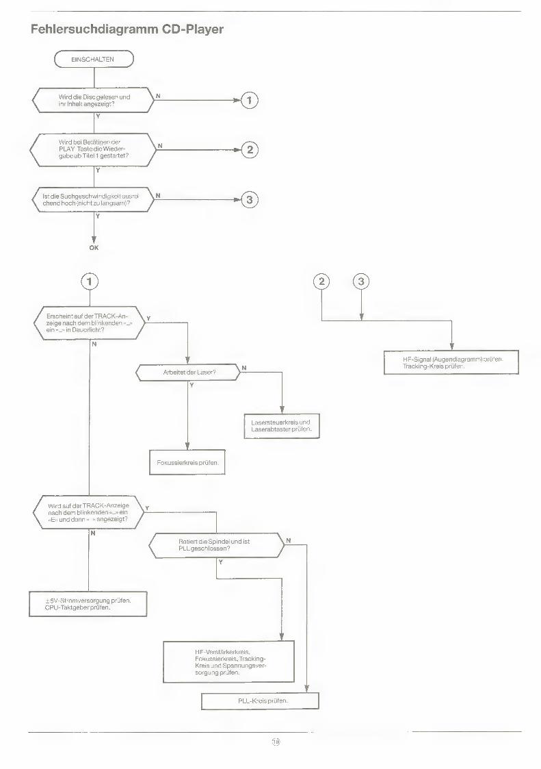
Fehlersuchdiagramm CD-Player
EINSCHALTEN
Wird bei Betatigen der PLAY-Taste die Wieder- gabe ab Titel 1 gestartet?
Ist die Suchgeschwindigkeit ausrei- chend hoch (nicht zu langsam)?
OK
Erscheint auf der TRACK-An- zeige nach dem blinkenden «_» ein «_» in Dauerlicht?
<
HF-Signal (Augendiagramm) priifen. Tracking-Kreis priifen.
Arbeitet der Laser? a
¥
Lasersteuerkreis und Laserabtaster priifen.
Fokussierkreis priifen.
Wird auf der TRACK-Anzeige nach dem blinkenden «_» ein «E» und dann «_» angezeigt?
Rotiert die Spindel undist N PLL geschlossen?
Y
+5V-Stromversorgung prifen. CPU-Taktgeber priifen.
HF-Verstarkerkreis, Fokussierkreis, Tracking- Kreis und Spannungsver- sorgung prifen.
PLL-Kreis priifen.
@

Troubleshooting Flowchart CD player
POWER ON
Does pressing the PLAY key start playback from the 1st track?
OK
Does the TRACK display show “--” after flashing “--”?
N Is laser light emitted?
Y
Check the focusing circuit block.
Does the TRACK display change from a flashing “--” to“ E” to “-"9
Is the spindle rotating N and the PLL locked?
Y
Check the +5V power supply. Check the CPU clock.
Check the RF amp circuit block, the focusing circuit block, the tracking circuit block, and the feed circuit block.
Check the PLL circuit block.
Check the laser drive circuit and pickup.
Check the RF signal (eye pattern). Check the tracking circuit block.

Ersatzteilliste elektrisch Queens 200 (ohne CD) Spare parts list electrical Queens 200 (without CD player)
Bestell-Nr./ Part. No.
48 009 00 48 010 00 48 011 00 48 013 00 48 012 00 46 850 00
48 002 00 13 558 00 46 829 00 31 481 00 38 286 00 32 997 00 37 730 00 40 799 00 21 596 00 26 131 00 32 998 00 46 830 00
21 736 00 12 036 00 37 957 00 13 545 00 08 012 00 03713 00 24 533 00 44 096 00 34 691 00 44 764 00
11 241 00 40 288 00 12 039 00 26 552 00 23 214 00 21 413 00 21 350 00 21 745 00 21 352 00
29 597 00 32 768 00 37 414 00
12 110 00 48 003 00 46 831 00 37 784 00 37 783 00 37 782 00 34 320 00 45 992 00 24 372 00 34 322 00 34 324 00 40 291 00 48 004 00 45 991 00 48 005 00 40 295 00 31 482 00 46 839 00
46 834 00 46 835 00 46 836 00 48 006 00
37 022 00 37 444 00 37 443 00 32 587 00 37 441 00 34 538 00 18 576 00 46 479 00 32 072 00 34 335 00 31 823 00 40 296 00 44 086 00 24 377 00
46 837 00 46 838 00 40 306 00 46 840 00 48 007 00 48 008 00 40 305 00 34 545 00 34 033 00 44 089 00 29 747 00 46 832 00 34 034 00 46 842 00 24 358 00 34 338 00 32 952 00
Bezeichnung
Tunerplatine Haupiplatine Displayplatine Klangreglerplatine Schalterplatine CD Tape Phono-Vorverstarker-Platine
IC LA 1265 IC LB 1416 IC LB 1641 IC UPD 1708 AG-728-00 IC TDA 2025 IC LA 3161 IC LA 2746 IC LA 3246 IC LA 3361 IC TC 4013 BP IC TC 4066 BP IC LC 6546C — 4059
Transistor 2 SC 1815 GR Transistor 2 SA 564 Q Transistor 2 SA 1177 E Transistor 2 SC 536 NP-F Transistor 2 SC 1317 Transistor 2 SC 1383 Q Transistor 2 SC 2634S Transistor 2 SB 544 E/F Transistor 2 SC 2878 Transistor 2 SD 1913 R
Diode 1 N 4148 Diode KV 1236 Z 2 Diode 10 D 1 SIL. Diode 30 D-1 FC Zenerdiode GZA 9,1 Y Zenerdiode GZA 15 Z Zenerdiode GZA 6,2 X oder Y Zenerdiode GZA 6,8 Y Zenerdiode GZA 5,6 Y
Leuchtdiode SLR-34VR85 {rot) Leuchtdiode SLR-34 DUS (orange) Leuchtdiode SEL 2310 S GN (griin)
Filter-Keramik 10.7-B Filter-Keramik BFU 455 CN 4 Ferritantenne LW/MW Spule 100 wH Spule 3,9 mH Spule 6,8 mH Drossel 100 wH Keramik-Filter SFZ 455 Spule AM Spule AM Spule Netzleitung Spule MW-Oszillator LB 0541 Spule, L6schoszillator Spule LW-Oszillator Oszillator Filter MPX Quarz 4,5 MHz Keramik-Oszillator CSA 4,00 MHz
Drehwiderstand 100k Balance Drehwiderstand 100k Klang Motor-Drehwiderstand 100k Volumen Drehwiderstand 10k Aussteuerung
Trimmpoti 1k Trimmpoti 2,2k Trimmpoti 10k Trimmpoti 22k Trimmpoti 4,7k Trimmpoti 47k Sicherungswiderstand 1 Ohm/'/s W Sicherungswiderstand 10 Ohm/'/2 W Sicherungswiderstand 22 Ohm/’2 W Sicherungswiderstand 39 Ohm/'2 W Sicherungswiderstand 220 Ohm/'/2 W Sicherungswiderstand 1 Ohm/1 W Trimmer Kondensator VTC 51A 144A 6pF Trimmer Kondensator VTC 51F 133A 30pF
Display Tuner LTP6M9011A Display CD LTP4R2011A Tuner FE 407/ET-A036 Lampchen 15V 30mA IR-Empfanger Queens 200 Netztrafo Microschalter Bandsorte Tipptaste A/W-Schiebeschalter Netzschalter Tastenschalter Tastensatz 7fach Funktion Mikrofonbuchse Buchse Kopfhérer Buchse Antenne Buchse Lautsprecher (Doppel) Buchse Chinch CD
Description Position inte tela ad |
Tuner P.C.B. F3 Main P.C.B. F7 Display P.C.B. F8 Tone P.C.B. cg Control P.C.B. CD Tape C8 Pre-amplifier phono C3
IC LA 1265 IC 1 B7 IC LB 1416 IC 405 B5 IC LB 1641 IC 303 B2 IC UPD 1708 AG-728-00 IC 201 D2 IC TDA 2025 IC 501/502 B7 IC LA 3161 IC 404/901 Bo IC LA 2746 IC 403 C3 IC LA 3246 IC 401 B2 IC LA 3361 IC 2 B1 IC TC 4013 BP IC 302 A8& IC TC 4066 BP IC 402 BO IC LC 6546C - 4059 IC 301 C4
Transistor 2 SC 1815 GR Diverse A3 Transistor 2 SA 564 Q Diverse A8& Transistor 2SA1177E Q1 A3 Transistor 2 SC 536 NP-F Diverse A3 Transistor 2 SC 1317 Diverse A5 Transistor 2 SC 1383 Q Q 601/609 A7 Transistor 2 SC 2634S Diverse A3 Transistor 2 SB 544 E/F Q 605 A5 Transistor 2 SC 2878 Q 501/502 A3 Transistor 2 SD 1913 R Q 602 Al
Diode 1 N 4148 Diverse A2 Diode KV 1236 Z 2 D1 B7 Diode 10D 1 SIL. Diverse A4 Diode 30 D-1 FC D 604-607 A4 Zenerdiode GZA 9.1 Y D 409 Al Zenerdiode GZA 15 Z D 603 A2 Zenerdiode GZA 6.2 X or Y D 207/304 A3 Zenerdiode GZA 6.8 Y D 602 A3 Zenerdiode GZA 5.6 Y D 605 A3
LED SLR-34VR5 (red) X 402/410 A4 LED SLR-34 DU5 (orange) X 403-409 A4 LED SEL 2310 S GN (green) X 401 A2
Ceramic Filter 10.7-B F1,2 A6 Ceramic Filter BFU 455 CN 4 F4 A8 Bar antenna coil LW/MW L2 B4 Coil 100 wH L 412/413 A4 Coil 3.9 mH L 409/410 A4 Coil 6.8 mH L 407/408 A4 Choke coil 100 wH Li,5 A3 AM Ceramic Filter F3 Bo Filter Coil L6 A6 AM IFT Coil IF 2 A4 Air Coil L 601/602 Al MW oscillator coil L4 A3 Tape oscillator coil L411 A7 LW oscillator coil L3 A4 Oscillator coil L 401-406 A7 Filter MPX L7/8 BO X'tal 4.5 MHz X 201 A8 Ceramic resonator CSA 4.00 MHz X 301 A7
Rotary VR 100k Balance VR 803 B1 Rotary VR 100k Tone VR 801/802 B2 Rotary VR with motor 100k Volume VR 501 DO Rotary VR 10k record level VR 401 co
Semi-fixed resistor 1k SFR 4 A4 Semi-fixed resistor 2.2k Diverse A3 Semi-fixed resistor 10k Diverse A3 Semi-fixed resistor 22k SFR 1 A4 Semi-fixed resistor 4.7k SFR 411 A3 Semi-fixed resistor 47k SFR 2 A2 Fuse resistor 1 Ohm/%4 W R 507-510 A2 Fuse resistor 10 Ohm/'2 W R 4137/4138 Al Fuse resistor 22 Ohm/2 W R 321 A3 Fuse resistor 39 Ohm//2 W R918 Al Fuse resistor 220 Ohm/'2 W R 606 A7 Fuse resistor 1 Ohm/1 W R 604 A3 Trimmer capacitor 6pF CcT2 A4 Trimmer capacitor 30 pF CT1 A3
Display Tuner LTP6M9011A LCD 201 C7 Display CD LTP4R2011A LCD 701 Ccé6 Tuner FE 407/ET-A036 D6 Pilot lamp 15V/30mA A4 IR-Receiver Queens 200 C2 Power transformer D7 Leaf switch tape select A6 Tact switch Diverse A3 Rec/PB switch S 401 a-d A8 Power switch SW 301 Bo Push switch SW 402-404 B1 Function switch SW 1-8 Ccé6 Microphone jack J 401 B3 Headphone jack J 502 Bo Antenna jack A6 Speaker DIN jack J 501 A7 2-Pin RCA jack A6
2)

Verdrahtungsplan Queens 200 Wiring diagram Queens 200
ere aire
g i | =.
ya FL aay. ie | iL} -____._. ATL d
Ket). =e Sh _—_————
aE o

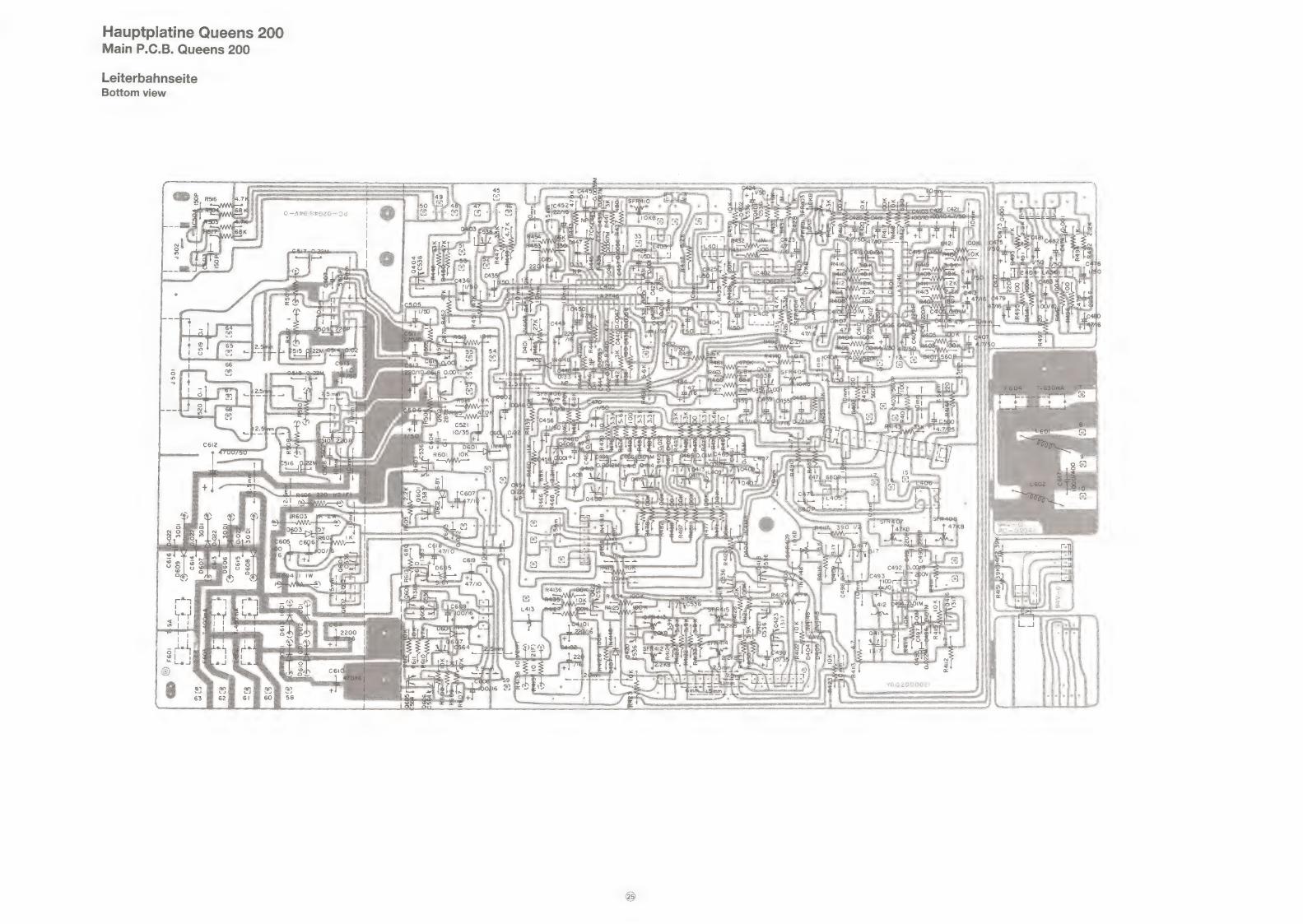
Hauptplatine Queens 200 Main P.C.B. Queens 200
Bestiickungsseite Top view
{Rg i |POOOG waa eras —_ =~ _ slelsis? NU ee A im Ls seo
Fee CF ai B iw: : : : 3 ae
orftesa eel echt
8) a I
ve : 4
leona J 123
am * : 5 4P2 9.0018 age
all Ly: a C493 | o
AW SD 1S
@ fee) ee
eel, i < B UB ni:
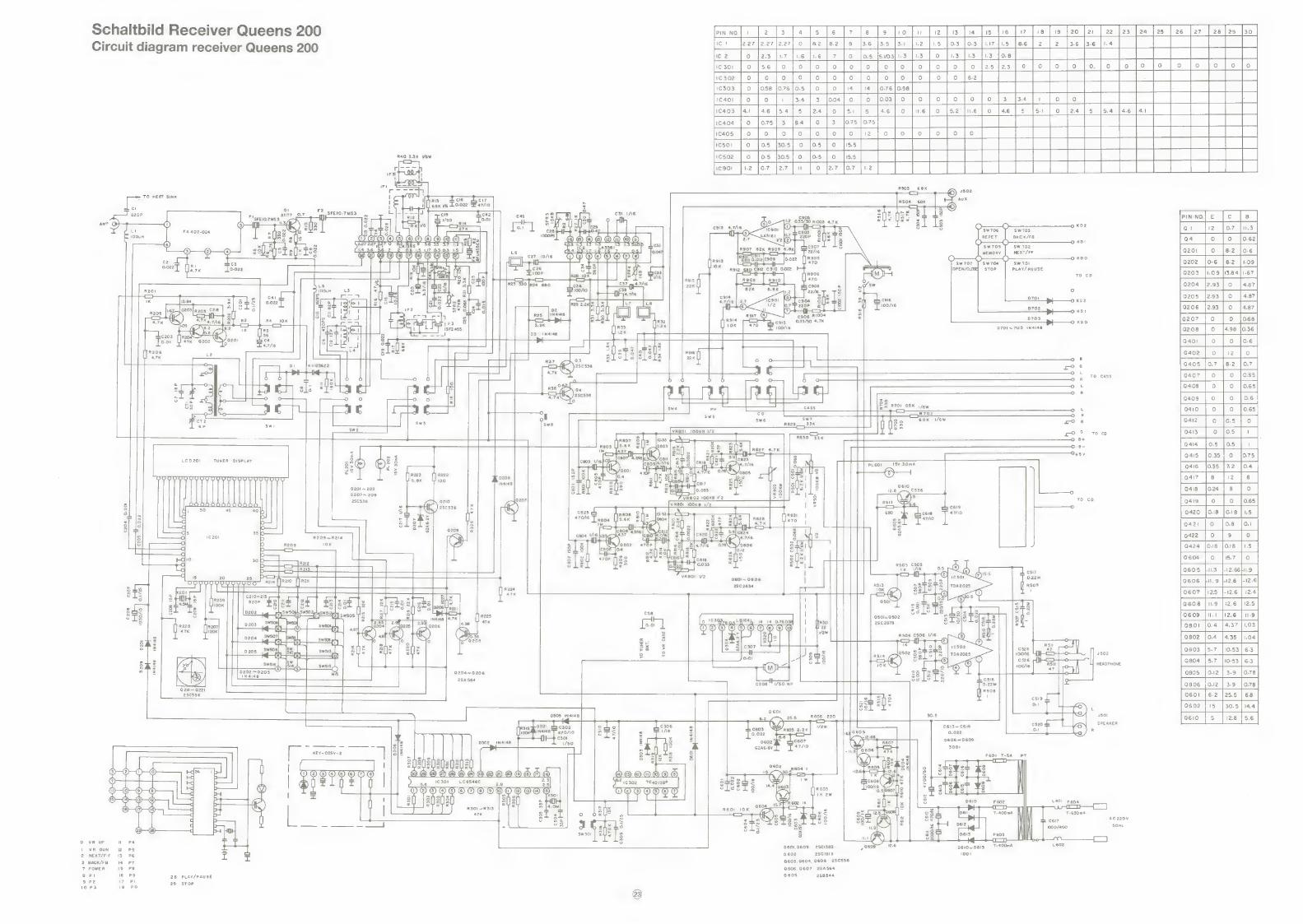
Schaltbild Receiver Queens 200 pweal) [2 1s 141s lel? lels lolu |elslu [ls |e |i [re [1 [20] Circuit diagram receiver Queens 200 Ic | 2.27 [2.27 |2.27 o |82 a | 8 3.6/3.5 [3-1 [12 [1.5 }03 [od [17 |.5 |e6 | 2
pe fas ja tae - |__|
IC 2 oO 2.3 13 [uz | o [3 13 1.3 [os a =
o-40 ]/o]0 | 0 |as{23]o ]o |o
o |o | oj o {62 |_|
0.58 | |
o}/o}oj}of}oj}o]3 {34 }1 oO
o jue] o {52 jue | o [46] 5 [51 | o [24
|__| L-| ical
cal |__| ae
n
reap. | 6 | 1 302 | o |
C303
1c401 °
1C403 om 1C404
1C405 =
re rea re 1c501
R40 3.3K Vew 1c502 =
pt or I HW ent
ia ae RS03_ 68K © +502 TO MEAT SINK | . RIS ci6 Ci7
lnsoa_eoe | = ei | 2 [leex ve L002 47/0 5 eos eax ~©) Qi ; ;
ao08 SFEIO-7MS3 L on ne 5] x = cst 1/6 sk E* g g g = x =e es 6 <
ant G ° g a — Ria a “fos []f]? 9 i e z< ral Te 2 ° x o 0.1 «Ua ic29 CG) : 8 g oO KD2
FA 407-024 eTrsTs oon « 0-4 2 SWTO3 S 1000PS TFOOQOMOOODs QOHHDONO® eases 9 Ko!
Ce ge Sk gages ur 0203 12 AT ae aw 702 - 7S Lé “ NEXT/FF
S DOO OOO OO® c27_ 10/16 aT Ty x am [ma] u sw 701 ee . c26 : PLAY/ PAUSE
is [eae mee () To co
7H a
ch cai6 OKS2 100/16
1 a OKS!I
c906 R1004 0703 cos (0.33/50 4.7K —o Kso 100/16 D701~703 IN4148
oO 8
ros OL OR TO CASS
e) L
OR
01 68K few <b = R702 SR
| gs 68K i/6w oo6
Pay 6 to cD
O B+ © B-
t ‘a OSV Lep201 TUNER DISPLAY =" 6 38> 8 PLEO! I5V30mA
> a® © sls O
OOUUUNDDUUUO VOUUUUUU 0208 elie IN4148 -
0201 ~203 3 2.8 cs36 0207~ 209 6 :
8 4 50 45 r3 < aa — - co céi9 3 ba S R = jee reece 680 co ces 47/10
z] {8 q 5 5 Tasos 5.6K J 82 Tae 3| [2 : : 3 Pe) Ef dia 6 q 0 ing ce08' a6] Ne s
ry O D R209~R214 RAG ee IK) ca 8 Us aaa 0 R209 10K ao] x Wx/osoz 470P 8
i O = BLE] ego fos E()3 8 re 6 2
— id : O al 3
Ug pF PH csi7 ie boo — | vreoi V2 0.22M
— Tall etl poe ; ‘a 2802634 R509 o=sk Nn ~ K201
els Sq s 2 °
37 re § be sl Ig sos 8 & cse ols ° 501.0502
°
7 Be2P 0.01 l
2sc 28768
47K w
3 R506 C506 1/I6 - = °°
g gu « 6 Pa > css
e 100/6 4502 a no \ cs26 i} Yo 100/16 HEADPHONE
o vay 0204~0206
XN | 2SA4 564
¢308 | 1/50 NP Q2i~ 221
28536
a6oi - 0305 IN4I48 B ae 25.5 R606 220 30.5 J501
AP — = cy © 306 ° c603 ae Vvew C613~CEI6 SEeanet
“70/0 2 6 = To.oze = 0-022 bs ey = 3 = peo2 o4c607 D606 ~D609
Fie, ea, aes fet . ] [j= GzA6.8Y 470 KEY-COSV-2 oto Lo S pT
8 als 2 8 32
7. ae ! 2602 R608 | 23 |e DOOOOOO® Qe OO @QOQA® - m6 Wa he ime he | |S » | l l 1630! F21c302 TC4o138P ots aL 2 QZ) tw iS 8 @ 5-8. Sis 3'L $ 14.4 1603 lo +
= OODO@O® OOOOOOD els R603 °
I 3 v7 1K 2W ° Pa
= a0) |s0303U 4) aU: 1 3 cs Pe $ D610 F602 R3OI~R3I3 2 ons é 2 1a
47K 8 o On4l > S T-400mA \ 3 g 3 Ac220v
—— Pees | « be | b ohx sé = SOHz
swso | 21 ss [3 F603 | VR UP W & G00 L602 VR DUN fz bs Q601,9609 2SCI383 D610~DEI3 7 400mA
NEXT/F-F 13 P6 id a a6o2 2Scisi3 1001 BACK/FB 14 P7 Q603.0604,Q608 2SC536
POWER 15 PS Q606,Q607 2SA564
Pt 16 P9 28 PLAY/PAUSE 605 288544
Re ne SB 29 sTOP 10 P3 18 PO

Schaltbild Recorder Queens 200 Circuit diagram cassette Queens 200
IT cai C5 47/6
R407 180 cai
pec C4105 £409, 0.01M f
220P
C405 4.7/16 0
c40l R403
seor | 1OoK'
C407 4.7/16 I
C403 2 I 560P
C406 4.7/6 1
wa R401 ome 3
> ° = 3[8 3 LcH ) 100 = c4io
— o ‘a eee
TAPE-A POOOR PAB oF FS] | 22°F | caiog 7 18K -> © = ©] Ica2 O.01M] R412
S a @ Een wrt A mr 180 c404 Ly cag
[sr L 476 L405 =--- R489
4.7K C469 a !
1/50 c4a7i 68oP
R485 3.3K Q.01M 100
R427 680
SFR403
10KB
rT ty
cage R484 C466 R480
x x . fn °
x = = a Lai2 2 $ 100uH = & o
a ° s S
220P ©4930
TAPE-A
ERACE
0.0012M 5-6 K
10K
R44
C498 0.1
Nor/Cr SW
sw408
C484 47/16
MIC JACK
GZAS.1Y
TAPE-B Nor /Cr SW
Sw407
PLAY SW
RBS. 10 if2
MOTOR SW
C4101 220/16
0407 R4i26 0422
R4129
Sw 402
DUBBING
SFR4N
c4a9 100/A6
15K
= =
C488 4.7/50
l
DOOO@O® @ O R4103_ “C48 ita R499 10K
Fags sa« | c486 4.7/50 R4100 10K = it
R402 5.1K
C451 220/16
SFR4I4 R 4133 SFRAIS
R410 68 2w
Q401~ 414 Q418~422 424
28C536 (2SC 2634)
Q415~417 423 2sci3i7
D401~ 408 IN4148
0409
GZA9.1Y
x402 410
LN 28RPL
x401 LN36GPL
X403~409
LN 48 YPL
ns 200
Hauptplatine Queens 200 Ma in P.C.B. Quee

Displayplatine/Schalterplatinen CD-—Tape, Queens 200 Phono-Vorverstarkerplatine Display P.C.B./Switch P.C.B.’s CD—Tape, Queens 200 Pre-amplifier P.C.B. phono
Bestuckungsseite Top view
Bestiickungsseite Top view
ee ah BE
Gat . tne
erat
Leiterbahnseite Bottom view Leiterbahnseite
Bottom view
Pheer ont le
h | rfcteg cb Ir fick Che ; Wwian| soe eae cn
we Fae ar ae ea
Pad en reels Ty = = Gateranaali

Tunerplatine Queens 200 Tuner P.C.B. Queens 200
Bestiickungsseite Top view
Klangreglerplatine Queens 200 Tone P.C.B. Queens 200
Bestiickungsseite Top view
or i
O | | “ OQ —
> if Lom]
= [1 ~]
o a
76
deoorred BAIS) hiries ee
Leiterbahnseite Bottom view
Leiterbahnseite Bottom view
—}————}
as Sees es ee al a
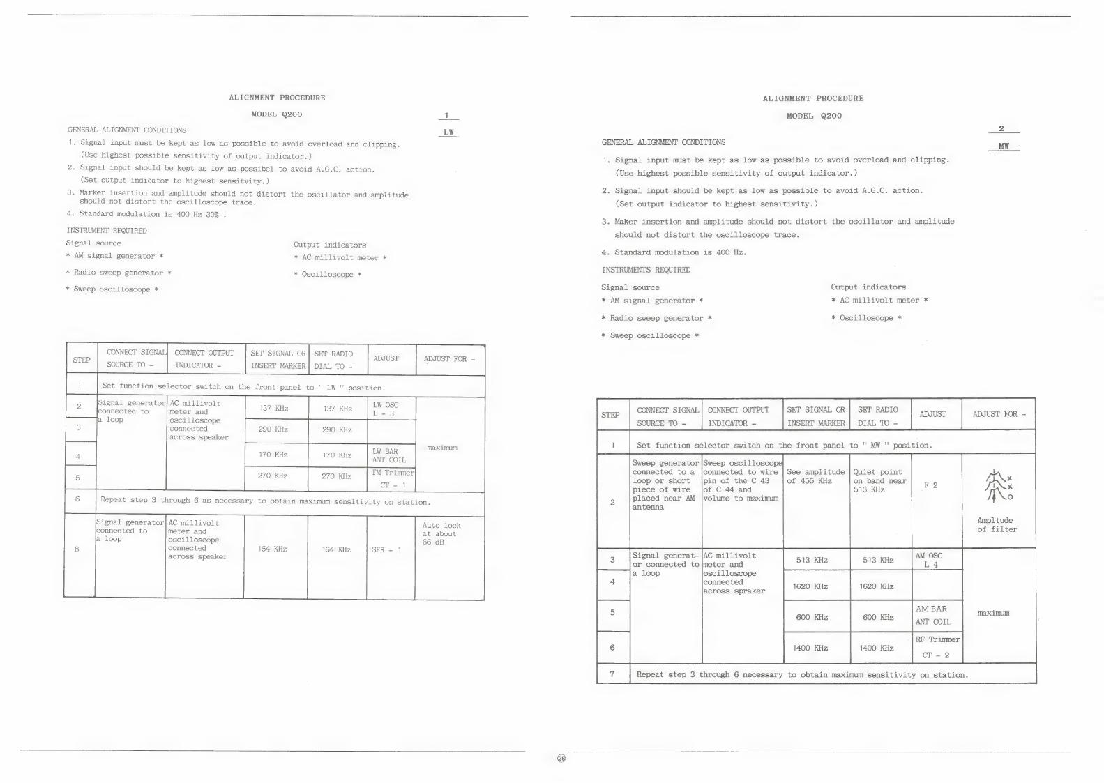
ALIGNMENT PROCEDURE
MODEL Q200 1
GENERAL ALIGNMENT CONDITIONS _LW_
1. Signal input must be kept as low as possible to avoid overload and clipping.
(Use highest possible sensitivity of output indicator.)
2. Signal input should be kept as low as possibel to avoid A.G.C. action.
(Set output indicator to highest sensitvity.)
3. Marker insertion and amplitude should not distort the oscillator and amplitude should not distort the oscilloscope trace.
4. Standard modulation is 400 Hz 30% :
INSTRUMENT REQUIRED
Signal source Output indicators
* AM signal generator * * AC millivolt meter *
* Radio sweep generator * * Oscilloscope *
* Sweep oscilloscope *
CONNECT SIGNAL} CONNECT OUTPUT
INDICATOR -
SET SIGNAL OR} SET RADIO ADJUST ADJUST FOR -
INSERT MARKER] DIAL TO -
Set function selector switch om the front panel to '" LW " position.
137 KHz 137 KHz mt Ox L-3
290 KHz 290 KHz
maximum LW BAR
270 KHz 270 Kz =| *™ Trinmer CT - 1
Repeat step 3 through 6 as necessary to obtain maximum sensitivity on station.
meter and
oscilloscope
connected
across speaker
Signal generator] AC millivolt meter and
oscilloscope
connected
across speaker
Auto lock
at about
66 dB 164 KHz 164 KHz SFR - 1
ALIGNMENT PROCEDURE
MODEL Q200
GENERAL ALIGNMENT CONDITIONS MW
1. Signal input must be kept as low as possible to avoid overload and clipping.
(Use highest possible sensitivity of output indicator.)
2. Signal input should be kept as low as possible to avoid A.G.C. action.
(Set output indicator to highest sensitivity. )
3. Maker insertion and amplitude should not distort the oscillator and amplitude
should not distort the oscilloscope trace.
4. Standard modulation is 400 Hz.
INSTRUMENTS REQUIRED
Signal source Output indicators
* AM signal generator * * AC millivolt meter *
* Radio sweep generator * * Oscilloscope *
* Sweep oscilloscope *
SET SIGNAL OR
INSERT MARKER
CONNECT OUTPUT
INDICATOR - SET RADIO | angust ADJUST FOR - DIAL TO -
Quiet point
on band near 513 KHz
Sweep generator |Sweep oscilloscope connected to a |connected to wire | See amplitude loop or short |pin of the C 43 of 455 KHz piece of wire jof C 44 and
placed near AM |volume to mzximum antenna
Amp1 tude ot filter
1620 KHz 1620 KHz |
AM BAR ; maximum
600 KHz 600 KHz ANT COIL
-| RF Trimmer 1400 KHz 1400 KHz
cT - 2
Repeat step 3 through 6 necessary to obtain maximum sensitivity on station.
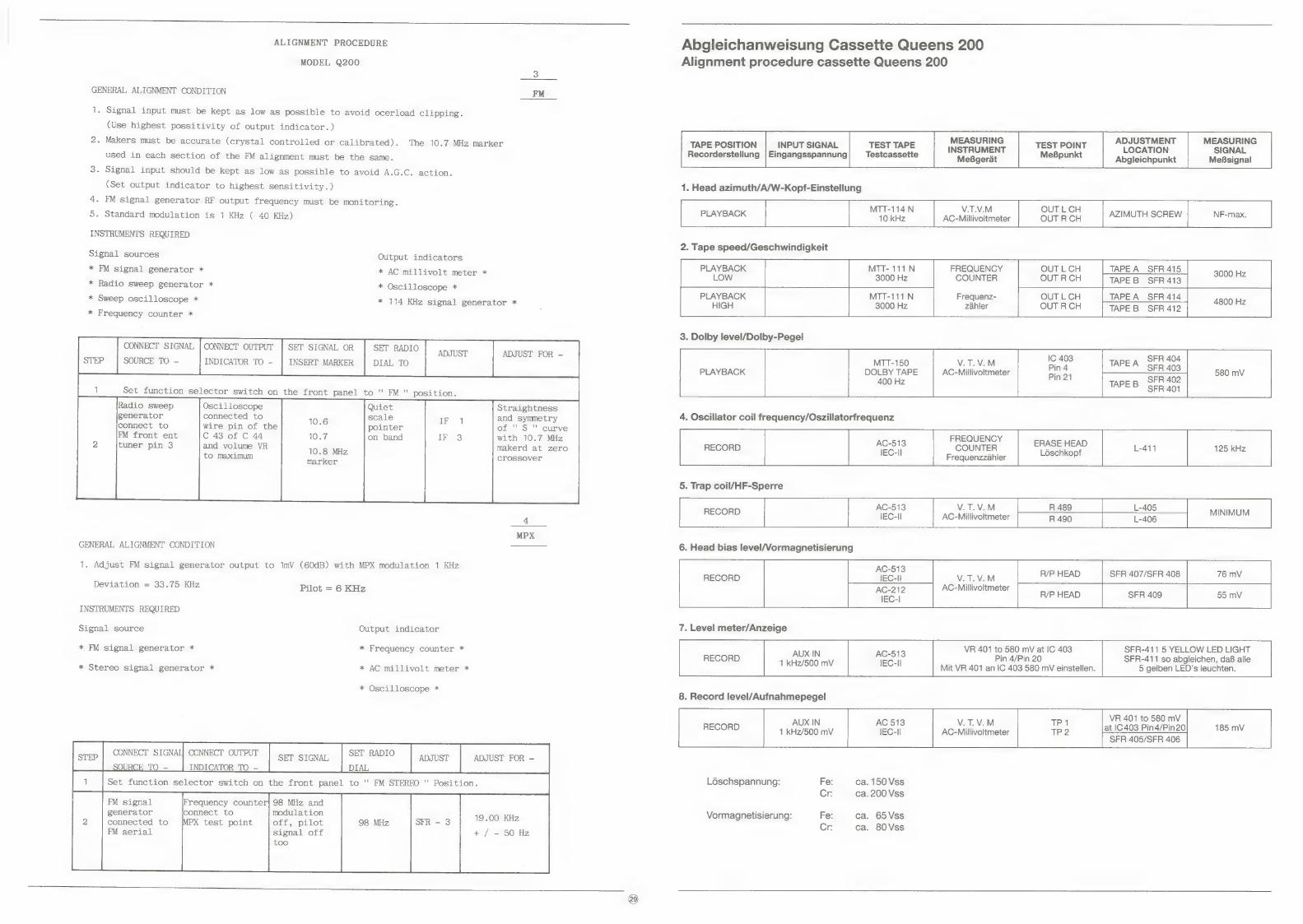
ALIGNMENT PROCEDURE
MODEL Q200
GENERAL ALIGNMENT CONDITION FM
1. Signal input must be kept as low as possible to avoid ocerload clipping.
(Use highest possitivity of output indicator.)
2. Makers must be accurate (crystal controlled or calibrated). The 10.7 MHz marker
used in each section of the FM alignment must be the same.
3. Signal input should be kept as low as possible to avoid A.G.C. action.
(Set output indicator to highest sensitivity.)
4. FM signal generator RF output frequency must be monitoring.
5. Standard modulation is 1 KHz ( 40 KHz)
INSTRUMENTS REQUIRED
Signal sources Output indicators
* FM signal generator * * AC millivolt meter *
* Radio sweep generator * * Oscilloscope *
* Sweep oscilloscope * * 114 KHz signal generator *
ent Bent0 ADJUST ADJUST FOR - DIAL TO
1 Set function selector switch on the front panel to '' FM '" position.
Quiet scale
pointer on band
* Frequency counter *
CONNECT SIGNAL | CONNECT OUTPUT
SOURCE TO - INDICATOR TO -
SET SIGNAL OR
INSERT MARKER
Radio sweep generator
connect to
FM front ent
tuner pin 3
Oscilloscope connected to
wire pin of the C 43 of C 44 and volume VR
to maximum
Straightness and symmetry of " S " curve with 10.7 MHz makerd at zero crossover
MPX GENERAL ALIGNMENT CONDITION
1. Adjust FM signal generator output to ImV (60dB) with MPX modulation 1 KHz
Deviation = 33.75 KHz Pilot = 6 KHz
INSTRUMENTS REQUIRED
Signal source Output indicator
* FM signal generator * * Frequency counter *
* Stereo signal generator * * AC millivolt meter *
* Oscilloscope *
pe CONNECT SIGNAL] CCNNECT OUTPUT SET SIGNAL SET RADIO ADJUST ADJUST FOR —
O - INDICATOR TO - ;
| 1 | set function selector switch on the front panel to '" FM STEREO " Position.
FM signal
generator connect to modulation connected to /MPX test point off, pilot 98 MHz 19.00 KHz FM aerial signal off + / - 50 Hz
too
Abgleichanweisung Cassette Queens 200 Alignment procedure cassette Queens 200
MEASURING ADJUSTMENT MEASURING TAPE POSITION INPUT SIGNAL TEST TAPE INSTRUMENT TEST POINT LOCATION SIGNAL Recorderstellung | Eingangsspannung Testcassette MeBpunkt
MeBgerat Abgleichpunkt MeBsignal
1. Head azimuth/A/W-Kopf-Einstellung
MTT-114.N V.T.V.M OUT L.CH PLAYBACK F 10 kHz AC-Millivoltmeter OUT RCH AZIMUTH SCREW
2. Tape speed/Geschwindigkeit
PLAYBACK MTT- 111N FREQUENCY OUT L CH | TAPEA SFR415 | A_SFR415 3000 Hz LOW 3000 Hz COUNTER OUT R CH TAPEB SFR 413
PLAYBACK MTT-111N Frequenz- OUT L CH TAPE A SFR 414 4800 Hz HIGH 3000 Hz zahler OUT R CH TAPEB SFR 412
3. Dolby level/Dolby-Pegel
SFR 404 SFR 403
SFR 402 SFR 401
MTT-150 V.T.V.M : TAPE A PLAYBACK DOLBY TAPE AC-Millivoltmeter
400 Hz TAPE B
4. Oscillator coil frequency/Oszillatorfrequenz
. FREQUENCY RECORD < COUNTER
Frequenzzahler
ERASE HEAD Ldéschkopf 125 kHz
5. Trap coil/HF-Sperre
AC-513 V.T.V.M R 489 L-405
6. Head bias level/Vormagnetisierung
VR 401 to 580 mV at IC 403 SFR-411 5 YELLOW LED LIGHT Pin 4/Pin 20 SFR-411 so abgleichen, daB alle
Mit VR 401 an IC 403 580 mV einstellen. 5 gelben LED’s leuchten.
AC-513 RECORD IEC-II V.T.V.M
AC-Millivoltmeter
R/P HEAD
7. Level meter/Anzeige
AUX IN AC-513 RECORD 1 kHz/500 mV IEC-II
8. Record level/Aufnahmepegel
VR 401 to 580 mV RECORD 4 kHz/500 mV e AC-Millivoltmeter at IC 403 Pin4/Pin20 185 mV
SFR 405/SFR 406
L6schspannung: Fe: ca. 150 Vss
Cr: ca. 200 Vss
Vormagnetisierung: Fe: ca. 65Vss Cr: ca. 80Vss
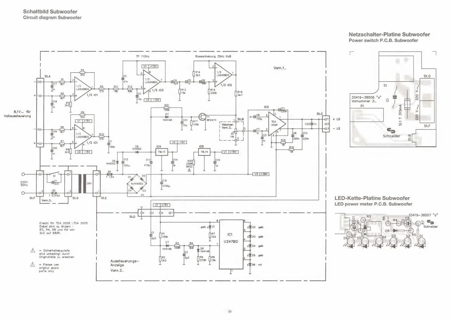
Schaltbild Subwoofer Circuit diagram Subwoofer
8,1V~ fir
Vollaussteuerung
220V 50Hz
St.F
- i & & oe} — - —_ - —_-—_- St.D
6 Ersatz fiir TDA 2026 :TDA 2025 Dabei sind zu &ndern : 2Yo2 geb R3, R4, R8 und RY von
2k2 auf 680R. | C1 2y2 D3 gelb
= D4 gelb
100R ms Ez = Sicherheitsbauteile sabe c2 Nate sind unbedingt durch : ZW5 gelb Originalteile zu ersetzen R2 2p2 R5 Wie 2
Aussteuerungs— 2k2 270R UB1Sk = Please use Anzeige Z¥D6 rot original spare parts only Vorn.2.. 1
220n |220n
R19 =
St.c
O
> Ee cg C10
Netzschalter-Platine Subwoofer
Power switch P.C.B. Subwoofer
rc
Vornummer 3.. oO
R1
33419-38506 “a”
220 VAL 220 V-~U
Si.1 T 315mA
Schneider a ma)
LED-Kette-Platine Subwoofer LED power meter P.C.B. Subwoofer
oa R3 _ ap5419-38507 "Q” wd | RS | 6.@-= b Ot b Es
Schneider
08 PE) | Oz 2" pa” D3 p2R5 p14

Verstarker-Platine Subwoofer
Amplifier P.C.B. Subwoofer
Spare parts subwoofer
Bestell-Nr./ Part. No.
47 063 00 47 061 00 47 066 00 47 079 00 41 970 00 27 747 00 18 331 00 18 336 00
27 638 00
38 487 00 11 760 00
39 258 00 38 510 00 23 257 00 38 511 00 38 512 00 38 286 00 38 007 00 31 729 00 38 555 00
39 259 00 38 486 00 38 030 00
39 260 00 02 424 00 31 463 00 38 502 00 38 500 00
47 069 00
ot ®) LS out 1!
a ° — a,”
SA 84 T 4@ ps s
+ 2 R3 Ptr D6 a A a A li
+3" : me Si.deT6A n
fF t
I <x
a = Vy ; 9 Be ao, e
En re rt ee | pee Crx Q— re Yi CS-= p= O- O ft R7 — sa 33419-38508"a BOS .
Ersatzteilliste Subwoofer
: a ‘43 Preisgruppe/ Bezeichnung Description Position Price key _|
Gehause Queens Subwoofer Housing Queens subwoofer DQ Abdeckgitter Queens Subwoofer (vorn) Mask Queens subwoofer (front) B8 Abdeckgitter Queens Subwoofer (oben) | Mask Queens subwoofer (top) B5 Frontteil Queens Subwoofer Front panel Queens subwoofer D5 Frontblende Queens (Plexiglas) Front window Queens (plexiglass) C4 FuB 50 mm mit Gummi Foot 50 mm with rubber A8& Tastenknopf 24 x 15,5 (Power on/off) Knob push 24 x 15.5 (Power on/off) A3 Drehknopf 14,6 (Bass level) Knob VR 14.6 (Bass level) A3
Lautsprecher 8 Ohm KW-200-1328 Speaker 8 Ohm KW-200-1328 D2
Trafo El 66 Power transformer El 66 D8 Buchse Lautsprecher Speaker jack A3
Verstarker-LP kpl. MS1 Amplifier P.C.B. assembly D5 Transistor BF 247 C Transistor BF 247 C T 101 Bo IC LA 6458 DS Dual-OP IC LA 6458 DS IC 101/102 AQ IC 78L15 IC 78L15 IC 105 A3 IC 79L15 IC 79L15 IC 104 A3 IC TDA 2025 IC TDA 2025 IC 103 B7 Zenerdiode ZPD 18(k) Zenerdiode ZPD 18 D 107 Al Diode 1 N 4002 Diode 1 N 4002 D101 A2 Sicherungswiderstand 330 Ohm/'s W Fuse resistor 330 Ohm/4 W R 120 A2
Netzschalter-LP kpI. MS1 Power switch P.C.B. assembly C3 Drehwiderstand Lautstarke 10 K Rotary VR 10 K volume R 301 B5 Netzschalter Power switch S$ 301 B2
LED-Kette-LP kpl. MS1 LED Power meter P.C.B. assembly C1 IC U 247 B Anzeige-IC IC U 247 B (indication IC) IC 201 B5 Diode 1 N 4148 (A) Diode 1 N 4148 (A) D 207/208 Al Leuchtdiode rot LED red D 206 A3 Leuchtdiode gelb LED yellow D 201-205 A3
Sty.-Verp. Queens Subwoofer/Unterschr. Polyfoam Queens subwoofer C6 Faltkarton Queens Subwoofer/Unterschr. Carton Queens subwoofer C8 47 068 00
#)

Ersatzteilliste Gehauseteile Queens 160
Spare parts list housing parts Queens 160
Bestell-Nr./ Part. No.
46 800 00 46 801 00 46 802 00 46 803 00
46 804 00 46 805 00 46 806 00 46 807 00 46 808 00 46 809 00 46 810 00 46 811 00 46 812 00 46 833 00
46 813 00 46 814 00 35 520 00
46 815 00 46 816 00 46 817 00
46 818 00 46 819 00 46 851 00 46 820 00
03 460 00 46 821 00
46 822 00 46 823 00 46 824 00 46 825 00
40 026 00 46 826 00 46 827 00 37 813 00 46 828 00
46 852 00 46 853 00 46 854 00 46 855 00 46 856 00
46 857 00 46 858 00 46 859 00 40 790 00 40 791 00 46 860 00 46 861 00 46 862 00
46 843 00 46 844 00 46 845 00
42 833 00 42 834 00 46 827 00
Bezeichnung Description
Frontteil Front panel Gehauseboden Bottom chassis Seitenteil rechts Seitenteil links
Taste On/Off Tastenblock CD 2fach Tastenblock CD 5fach Taste Dubbing (2) Tastenblock Tuning Tastenblock 13fach Tastenblende Drehknopf 19 mm (Klang, Balance) Drehknopf 52 mm (Lautstarke) Taste Funktionswahl (7)
Frontblende (Plexiglas) Blende CD-Schublade Schriftzug Schneider
Abdeckhaube Zarge Plattenspieler Riickwand
Plattenspieler kpl. CD-Spieler kpl. Doppel-Cass.-Mechanik TN-21ZSW-494 Fernbedienungsgeber Queens
Plattenpuck Matte Plattenteller
Streuglas Tunerdisplay Streuglas CD-Display Reflektor Tunerdisplay Reflektor CD-Display
Steckhilse Funktionsschalter Pulley Zahlwerk GehausefuB Scharnier Abdeckhaube Sicherungsknebel Funktionsschalter
Cassettenfach Cassettenfachdeckel A Cassettenfachdeckel B CR-Taste schmal CR-Taste breit
Taste Zahlwerk Zahlwerkriemen Zahliwerk Dampfrad Dampfradhalter Feder Cassettenfach Feder AW-Schalter Zierschraube
Karton Queens 160/200 Styropor-Verpackung rechts Styropor-Verpackung links
Queens 160 LS links Queens 160 LS rechts GehausefuB LS-Box
Side panel right Side panel left
Button on/off Preset button CD 2x Preset button CD 5x Button dubbing (2) Button tuning Preset button 13x Preset button frame Knob VR 19 mm (Tone, balance) Knob main VR (Volume) Button function (7)
LCD window CD door Badge Schneider
Dust cover Player board Back board
Player assembly CD player Double cass. mechanic TN-21ZSW-494 Remote control
Adapter 45 rom Turn-table mat
Screen tuner display Screen CD display Reflector tuner display Reflector CD display
Spacer function switch Pulley tape counter Foot Hinge assembly Spacer function switch
Cassette case Cassette window A Cassette window B Cass. key small Cass. key large
Counter knob Counter belt Tape counter Damper gear Damper holder Cass. open spring Cass. rec. spring Screw bolt
Carton Queens 160/200 Poly foam right Poly foam left
Queens 160 LS left Queens 160 LS right Foot speakerbox
Position
rPrrr>r FrYryYr OOMNOO ROMA
rrrry> ticks ok kik ROM=A0
A15 A16 A17
A18 A19 A20
A2i A22 C1 A23
A 24 A25
=|WNO® NOOO
9Q000000 C0000 va00nD woOD NABO-OOON Ou Wh 28Rs cok ek ek, ak
Preisgruppe/ Price key
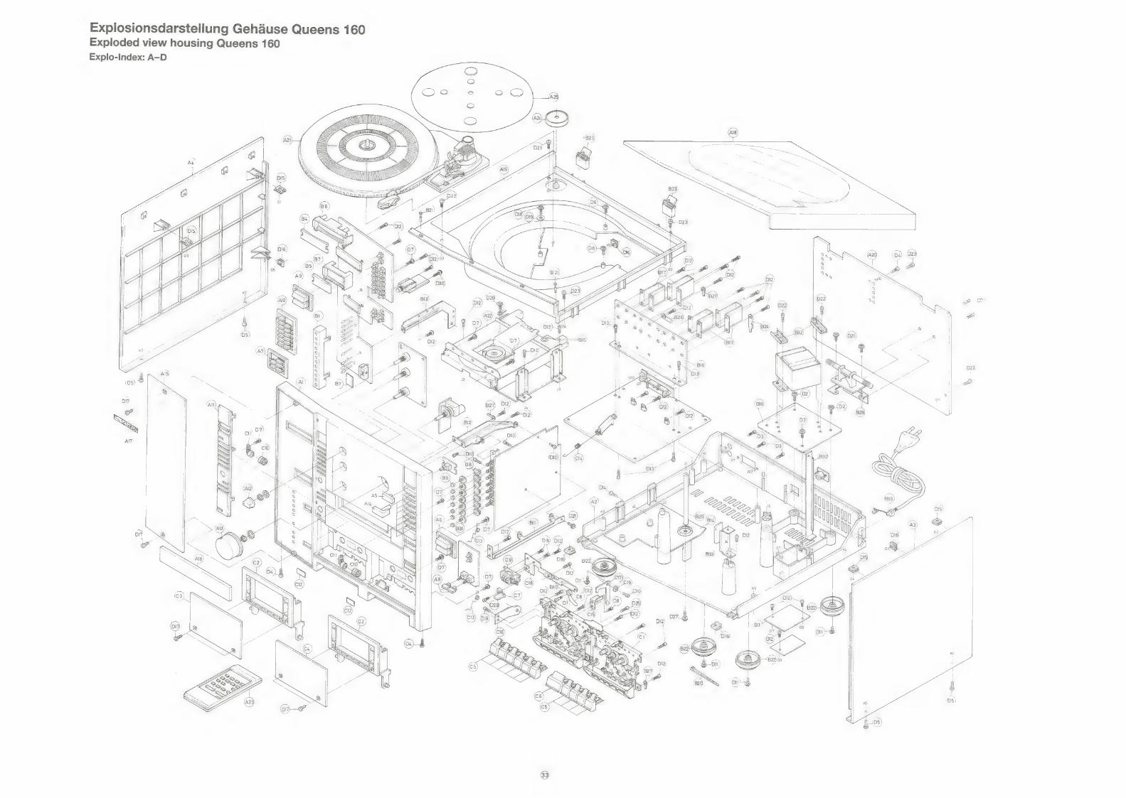
Explosionsdarstellung Gehause Queens 160 Exploded view housing Queens 160
Explo-Index: A-D
\AN
A
A /

Explosionsdarstellung Cassettenmechanik Queens 160 Exploded view cassette mechanism Queens 160
Explo-Index: CM
Ersatzteilliste Cassettenmechanik Queens 160 Spare parts list cassette mechanism Queens 160
Bezeichnung Bestell-Nr./ Part. No.
46 863 00 46 417 00 44 130 00 44 131 00 32 428 00 46 864 00 32 423 00 44 132 00 45 760 00 32 432 00 32 435 00 32 436 00 44 135 00 44 137 00 44 138 00 46 865 00 46 866 00 44 136 00 44 140 00 44 319 00 44 14100 44 142 00 46 436 00 32 453 00 32 454 00 44 778 00 40 818 00 46 418 00 32 459 00
34 348 00 34 349 00 24 513 00 46 177 00
32 451 00 44 133 00 32 462 00 46 867 00 46 868 00
Feder Pauserasthebel Pauserasthebel Druckfeder Pauserasthebel Sicherungsstépsel Pause Feder Tastenhebel (Vor-, Ruicklauf) Feder Aufnahmetaste Feder Tastenhebel (Stop, Pause) Mikroschalter MSW L 541 T Feder Kopftragerplatte Feder Léschkopf Feder A/W-Kopf Bandandruckrolle kpl. Tasthebel Endabschaltung Rutschkupplung kpl. Riemen Rutschkupplung Schwungmasse AW-Laufwerk Schwungmasse Wiedergabe-Laufwerk Kurvenzahnrad Zahnrad Vorlauf Feder Wickelteller links Wickelteller links Wickelteller rechts kpl. Spange Wickelteller Gummipuffer Motor Schraube Motor Pulley-Motor Antriebsriemen Gleithebel Eject Cassettenandruckfeder
Wiedergabekopf A/W-Kopf Léschkopf Antriebsmotor SH U 2.L
Aufnahmesperrhebel Mikroschalter MSW-17820 MVDO Sicherungsscheibe Schwungmasse Kick-Hebel Doppelpause Feder Kick-Hebel
Ersatzteilliste Plattenspieler Queens 160/Queens 200 Spare parts list player Queens 160/Queens 200
Bestell-Nr./ Part. No. Bezeichnung
46 819 00 Plattenspieler kpl.
48 018 00 Plattentelier mit Zahnrad 48 019 00 Tonarm kpl. mit System 48 020 00 Tonarmiift 46 182 00 Liftknopf 03 460 00 Puck 34 357 00 Clip Tonarmstitze 48 021 00 Gleitschieber Motorschalter 48 022 00 Kurvenrad 48 023 00 Endschalthebel 48 024 00 Nadelschutz 40 829 00 Motorpulley 32 868 00 Sicherungsring Plattenteller 48 025 00 Gleithebel 14 229 00 Sicherungsring Kurvenrad 48 026 00 Lagergummi unten 48 027 00 Lagergummi oben (2) 48 028 00 Gummiring 34 371 00 Antriebsriemen 48 029 00 Feder Gleithebel 48 030 00 Lifthebel 48 031 00 Schubstange
46 423 00 Motor SHR 2 R 48 032 00 System 48 033 00 Abtastnadel
48 034 00 Schiebeschalter 33/45 46 014 00 Microschalter Motor —
ere Fa Preisgruppe/ Description Position Price key
Spring pause lever CM 10 AO Pause lever CM 11 AO Spring pause lever CM 12 AO Pause stopper CM 13 AO Button lever spring (FF, REW.) CM 14 A3 Spring rec. button CM 21 AO Button lever spring (Pause, Stop) CM 22 A3 Leaf switch MSW L 541 T CM 23 A4 Spring head panel CM 29 A Erase head spring CM 33 A3 Spring R/P head CM 34 A3 Pinch roller assembly CM 35 B6 Sensing lever stop CM 38 Al RF clutch assembly CM 39 A7 Belt RF clutch CM 40 A4 Fly-wheel R/P CM 44 B7 Fly-wheel Play mechanism CM 43 B7 Cam gear CM 47 A2 FF gear CM 49 Al Back tension spring CM 50 AO Supply reel CM 51 A3 Take-up reel assembly CM 52 A4 Sensor CM 53 Al Motor rubber CM 56 A2 Motor collar screw CM 57 A2 Pulley motor CM 58 A6 Main belt CM 59 A3 Eject slide lever CM 62 A3 Pack spring CM 64 A5
Play head CM 65 Bé6 R/P head CM 66 B6 Erase head CM 67 BO Drive motor SHU 2L CM 68 Cé6
Record safety lever CM 69 A5 Leaf switch MSW-17820 MVDO CM 70 A7 Polyslider washer fly-wheel CM 85 AO Kick lever pause CM 91 A Spring kick lever CM 95 AO
boas a” Preisgruppe/ Description Position Price key
Player assembly A21 E5
Turn-table with gear PL 2+11 C3 Tone arm assembly with system D5 Cueing shaft PL6 A2 Knob PL. 7 Al Adapter PL 8 A2 Pick-up cramper PL9 A Trip pawl PL 10 A2 Cam gear PL.12.., AQ Control lever PL. 13.;. A3 Stylus cover PL 14 Al Motor pulley PL 15 A2 E-ring turn-table PL 22 AO Drive plate PL 24... A7 E-ring cam gear PL 28 Al Grommet PL 33 A2 Grommet (2) PL 34 A Insert rubber PL 35 AO Belt PL 36 Bo Spring drive plate PL 37 A2 Cueing lever PL 38 A2 Control lever PL 40 A3
Motor SHR 2 R PL 46 G5 Cartridge PL 47 D1 Stylus PL 48 C4
Slide switch PL 49 BO Leaf switch PL 50 A5
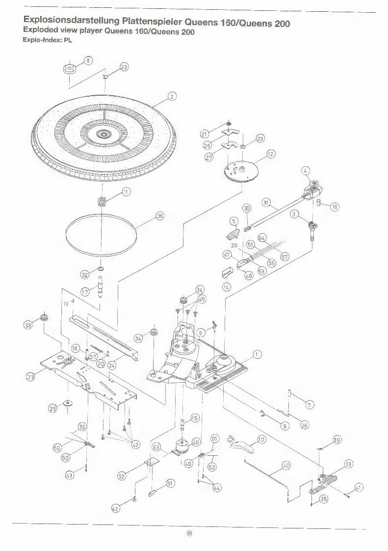
/Queens 200 Explosionsdarstellung Plattenspieler Queens 160 Exploded view player Queens 160/Queens 200 Explo-Index: PL

Ersatzteilliste Gehauseteile Queens 200 Spare parts list housing parts Queens 200
=
Sri Bezeichnung Description Position i aad
46 995 00 Frontteil Front panel A 1 C7 46 996 00 Gehauseboden Bottom chassis A 2 G5 46 802 00 Seitenteil rechts Side panel right A 3 C3 46 803 00 Seitenteil links Side panel left A 4 C2
46 804 00 Taste On/Off Button on/off A 5 Al 46 805 00 Tastenblock CD 2fach Preset button CD 2x A 6 A2 46 806 00 Tastenblock CD 5fach Preset button CD 5x A 7 A2 46 807 00 Taste Dubbing (2) Button dubbing (2) A 8 AO 46 808 00 Tastenblock Tuning Button tuning A 9 A2 46 809 00 Tastenblock 13fach Preset button 13x A10 A3 46 997 00 Tastenblende Preset button frame A111 . A7 46 811 00 Drehknopf 19 mm (Klang, Balance) Knob VR 19 mm (Tone, balance) A12 Al 46 812 00 Drehknopf 52 mm (Lautstarke) Knob Main VR (Volume) A138 B4 46 833 00 Taste Funktionswahl (7) Button function (7) A14 A2
46 813 00 Frontblende (Plexiglas) LCD window A15 C8 46 814 00 Blende CD-Schublade CD door A116 A7 35 520 00 Schriftzug Schneider Badge Schneider A17 A3
46 815 00 Abdeckhaube Dust cover A18 cg 46 816 00 Zarge Plattenspieler Player board A19 C3 46 817 00 Riickwand Back board A20 B5
46 818 00 Plattenspieler kpl. Player assembly A21 E5 46 819 00 CD-Spieler kpl. CD player A 22 G2 46 998 00 Cass.-Mech. A/W TN-21ZSB-495 Cass. mech. R/P TN-21ZSB-495 C1 EO 46 999 00 Cass.-Mech. Wiedergabe TN-21ZSB-496 Cass. mech. Play TN-21ZSB-496 C21 D9 46 820 00 Fernbedienungsgeber Queens Remote control A 23 D5
03 460 00 Plattenpuck Adapter 45 rom A24 A2 46 821 00 Matte Plattenteller Turn-table mat A25 B5
46 822 00 Streuglas Tunerdisplay Screen tuner display B 4 A3 46 823 00 Streuglas CD-Display Screen CD display B 5 A2 46 824 00 Reflektor Tunerdisplay Reflector tuner display B 6 A2 46 825 00 Reflektor CD-Display Reflector CD display B7 A2
40 026 00 Steckhulse Funktionsschalter Spacer function switch B 8 Al 46 826 00 Pulley Zahlwerk Pulley tape counter B10 AO 46 827 00 GehausefuB Foot B22 AQ 37 813 00 Scharnier Abdeckhaube Hinge assembly B23 Bo 46 828 00 Sicherungsknebel Funktionsschalter Spacer function switch B31 Al
46 852 00 Cassettenfach Cassette case C2 A5 46 853 00 Cassettenfachdeckel A Cassette window A C 3 B1 46 854 00 Cassettenfachdeckel B Cassette window B Cc 4 B1 46 855 00 CR-Taste schmal Cass. key small C5 A2 46 856 00 CR-Taste breit Cass. key large Cc 6 A2
46 857 00 Taste Zahlwerk Counter knob C7 Al 46 858 00 Zahlwerkriemen Counter belt Cc 8 A2 46 859 00 Zahiwerk Tape counter Cc 9 B4 40 790 00 Dampfrad Damper gear C10 A2 40 791 00 Dampfradhalter Damper holder C11 A2 46 860 00 Feder Cassettenfach Cass. open spring C13 Al 48 000 00 Feder AW-Schalter Cass. rec. spring C14 A2 46 862 00 Zierschraube Screw bolt D17 A1
46 843 00 Karton Queens 160/200 Carton Queens 160/200 C3 46 844 00 Styropor-Verpackung rechts Poly foam right co 46 845 00 Styropor-Verpackung links Poly foam left co
42 835 00 Queens 200 LS links Queens 200 LS left 42 836 00 Queens 200 LS rechts Queens 200 LS right 46 827 00 Gehausefu8 LS-Box Foot speakerbox AQ

Explosionsdarstellung Gehduse Queens 200 Exploded view housing Queens 200 Explo-Index: A-—D
—__\
(Z
RANE’.
9y guy
40
\V
J
g \
. z
7
~ JTKG
27 QR
& MW
(AL
” LITBMU
2
ey
ee
i
Ti
“6
Wa

Explosionsdarstellung Cassettenmechanik A/W Queens 200 Explosionsdarstellung Cassettenmechanik Wiedergabe Queens 200 Exploded view cassette mechanism R/P Queens 200 Exploded view cassette mechanism playback Queens 200
Explo-Index: CM Explo-Index: CM
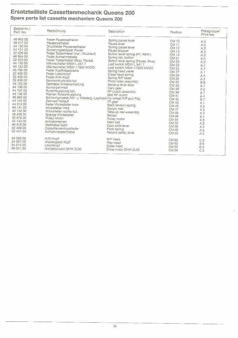
Ersatzteilliste Cassettenmechanik Queens 200 Spare parts list cassette mechanism Queens 200
|
esr Bezeichnung Description Position ee e/
46 863 00 Feder Pauserasthebel Spring pause lever CM 10 AO 46 417 00 Pauserasthebel Pause lever CM 11 AO 44 130 00 Druckfeder Pauserasthebel Spring pause lever CM 12 AO 44 131 00 Sicherungsstépsel Pause Pause stopper CM 13 AO 32 428 00 Feder Tastenhebel (Vor-, Riicklauf) Button lever spring (FF, REW.) CM 14 A3 46 864 00 Feder Aufnahmetaste Spring rec. button CM 21 AO 32 423 00 Feder Tastenhebel (Stop, Pause) Button lever spring (Pause, Stop) CM 22 A3 44 132 00 Mikroschalter MSW L 541 T Leaf switch MSW L 541 T CM 23 A4 44 133 00 Mikroschalter MSW-17820 MVDO Leaf switch MSW-17820 MVDO CM 24 A7 45 760 00 Feder Kopftragerplatte Spring head panel CM 27 Al 32 432 00 Feder Loschkopf Erase head spring CM 28 A3 32 435 00 Feder A/W-Kopf Spring R/P head CM 29 A3 32 436 00 Bandandruckrolle kpl. Pinch roller assembly CM 32 B6 44 135 00 Tasthebel Endabschaltung Sensing lever stop CM 35 Al 44 136 00 Kurvenzahnrad Cam gear CM 38 A2 44 137 00 Rutschkupplung kpl. RF clutch assembly CM 39 A7 44 138 00 Riemen Rutschkupplung Belt RF clutch CM 41 A4 46 865 00 Schwungmasse AW- u. Wiederg.-Laufwerk Fly-wheel R/P and Play CM 43 B7 44 140 00 Zahnrad Vorlauf FF gear CM 45 Al 44 319 00 Feder Wickelteller links Back tension spring CM 46 AO 44 141 00 Wickelteller links Supply reel CM 47 A3 44 142 00 Wickelteller rechts kpl. Take-up reel assembly CM 48 A4 46 436 00 Spange Wickelteller Sensor CM 49 Al 32 876 00 Pulley-Motor Pulley motor CM 54 A5 44 143 00 Antriebsriemen Main belt CM 55 A2 46 418 00 Gleithebel Eject Eject slide lever CM 58 A3 32 459 00 Cassettenandruckfeder Pack spring CM 59 A5 32 451 00 Aufnahmesperrhebel Record safety lever CM 60 A5
34 056 00 A/W-Kopf R/P head CM 62 C3 34 057 00 Wiedergabe-Kopf Play head CM 62 BQ 24 513 00 Loschkopf Erase head CM 63 BO 48 001 00 Antriebsmotor SHW 2L00 Drive motor SHW 2L00 CM 64 C3 =
Bitte bei Ersatzteilbestellung die genaue Bezeichnung und Ident-Nr. (siehe Typenschild) des Gerates
sowie Bestell-Nummer und Positions-Nummer des Ersatzteils angeben.
For ordering of spare parts please state exact description and ident no. of unit (see silver rating label on
the backside of unit) as well as part no. and position no. of required spare parts.
Benuitzen Sie:
Telex: 531516
oder
(a) * 317298 #
oder
Telefax: 082 45/5 1326
Technische Anderungen vorbehalten. Technical modifications reserved. 4679900 HDS 68174/8000/43/89


![DELTAtec 90P Feed - Boehlerit · 7 DELTAtec 90P Feed Systemgröße 10 System size 10 Abmessungen [mm] Dimensions [mm] Bestellbezeichnung Ordering code Ident.-Nr. Ident.-No. Verfügbarkeit](https://static.fdocuments.net/doc/165x107/604631b2c64a7264c42d08d5/deltatec-90p-feed-boehlerit-7-deltatec-90p-feed-systemgre-10-system-size-10.jpg)