Service Manual€¦ · · 2015-11-14Service Manual DUCT FREE SPLIT SYSTEM R--410A HIGH WALL...
34
Specifications subject to change without notice. 421 08 9300 00 April 2008 Service Manual DUCT FREE SPLIT SYSTEM R--410A HIGH WALL DFS4(A/H) -- System DFC4(A/H)3 -- Outdoor DFF4(A/H)H -- Indoor TABLE OF CONTENTS PAGE SAFETY CONSIDERATIONS 1 ............................ MODEL NUMBER INDENTIFICATION GUIDE 2 .............. STANDARD FEATURES AND ACCESSORIES 3 ............. SPECIFICATIONS -- COOLING ONLY 4 ..................... SPECIFICATIONS -- HEAT PUMP UNITS 5 .................. DIMENSIONS 6 .......................................... SERVICE VALVE LOCATIONS 6 ........................... CLEARANCES 7 ......................................... SYSTEM OPERATING ENVELOPE 8 ....................... ELECTRICAL DATA 8 .................................... WIRING 9 ............................................... CONNECTION DIAGRAMS 9 .............................. WIRING DIAGRAMS 10 -- 14 ............................... REFRIGERATION CYCLE DIAGRAM 15 .................... REFRIGERANT LINES 16 ................................. SYSTEM EVACUATION AND CHARGING 17 ................ CONTROL SYSTEM & SYSTEM SAFETIES 18 .............. 3 MINUTE TIME DELAY 18 ................................ COMPRESSOR OVERCURRENT PROTECTION 18 -- 19 ...... SEQUENCE OF OPERATION 20 ........................... MODES OF OPERATION 20 -- 22 ........................... TROUBLESHOOTING 23 -- 34 ............................. SAFETY CONSIDERATIONS Improper installation, adjustment, alteration, service, maintenance, or use can cause explosion, fire, electrical shock, or other conditions which may cause death, personal injury, or property damage. Consult a qualified installer, service agency, or your distributor or branch for information or assistance. The qualified installer or agency must use factory--authorized kits or accessories when modifying this product. Refer to the individual instructions packaged with the kits or accessories when installing. Follow all safety codes. Wear safety glasses, protective clothing, and work gloves. Use quenching cloth for brazing operations. Have fire extinguisher available. Read these instructions thoroughly and follow all warnings or cautions included in literature and attached to the unit. Consult local building codes and National Electrical Code (NEC) for special requirements. Recognize safety information. This is the safety--alert symbol ! ! When you see this symbol on the unit and in instructions or manuals, be alert to the potential for personal injury. Understand these signal words: DANGER, WARNING, and CAUTION. These words are used with the safety--alert symbol. DANGER identifies the most serious hazards which will result in severe personal injury or death. WARNING signifies hazards which could result in personal injury or death. CAUTION is used to identify unsafe practices which may result in minor personal injury or product and property damage. NOTE is used to highlight suggestions which will result in enhanced installation, reliability, or operation. ! WARNING ELECTRICAL SHOCK HAZARD Failure to follow this warning could result in personal injury or death. Before installing, modifying, or servicing system, main electrical disconnect switch must be in the OFF position. There may be more than 1 disconnect switch. Lock out and tag switch with a suitable warning label. INTRODUCTION Section 1 of this Service Manual provides the necessary information to service, repair, and maintain the Duct Free Splits with R410--A air conditioners and heat pumps. Section 2 of this manual is an appendix with data required to perform troubleshooting. Use the Table of Contents to locate a desired topic.
Transcript of Service Manual€¦ · · 2015-11-14Service Manual DUCT FREE SPLIT SYSTEM R--410A HIGH WALL...

Specifications subject to change without notice. 421 08 9300 00 April 2008
Service ManualDUCT FREE SPLIT SYSTEM R--410A
HIGH WALLDFS4(A/H) -- System
DFC4(A/H)3 -- OutdoorDFF4(A/H)H -- Indoor
TABLE OF CONTENTS
PAGE
SAFETY CONSIDERATIONS 1. . . . . . . . . . . . . . . . . . . . . . . . . . . .
MODEL NUMBER INDENTIFICATION GUIDE 2. . . . . . . . . . . . . .
STANDARD FEATURES AND ACCESSORIES 3. . . . . . . . . . . . .
SPECIFICATIONS -- COOLING ONLY 4. . . . . . . . . . . . . . . . . . . . .
SPECIFICATIONS -- HEAT PUMP UNITS 5. . . . . . . . . . . . . . . . . .
DIMENSIONS 6. . . . . . . . . . . . . . . . . . . . . . . . . . . . . . . . . . . . . . . . . .
SERVICE VALVE LOCATIONS 6. . . . . . . . . . . . . . . . . . . . . . . . . . .
CLEARANCES 7. . . . . . . . . . . . . . . . . . . . . . . . . . . . . . . . . . . . . . . . .
SYSTEM OPERATING ENVELOPE 8. . . . . . . . . . . . . . . . . . . . . . .
ELECTRICAL DATA 8. . . . . . . . . . . . . . . . . . . . . . . . . . . . . . . . . . . .
WIRING 9. . . . . . . . . . . . . . . . . . . . . . . . . . . . . . . . . . . . . . . . . . . . . . .
CONNECTION DIAGRAMS 9. . . . . . . . . . . . . . . . . . . . . . . . . . . . . .
WIRING DIAGRAMS 10 -- 14. . . . . . . . . . . . . . . . . . . . . . . . . . . . . . .
REFRIGERATION CYCLE DIAGRAM 15. . . . . . . . . . . . . . . . . . . .
REFRIGERANT LINES 16. . . . . . . . . . . . . . . . . . . . . . . . . . . . . . . . .
SYSTEM EVACUATION AND CHARGING 17. . . . . . . . . . . . . . . .
CONTROL SYSTEM & SYSTEM SAFETIES 18. . . . . . . . . . . . . .
3 MINUTE TIME DELAY 18. . . . . . . . . . . . . . . . . . . . . . . . . . . . . . . .
COMPRESSOR OVERCURRENT PROTECTION 18 -- 19. . . . . .
SEQUENCE OF OPERATION 20. . . . . . . . . . . . . . . . . . . . . . . . . . .
MODES OF OPERATION 20 -- 22. . . . . . . . . . . . . . . . . . . . . . . . . . .
TROUBLESHOOTING 23 -- 34. . . . . . . . . . . . . . . . . . . . . . . . . . . . .
SAFETY CONSIDERATIONSImproper installation, adjustment, alteration, service,maintenance, or use can cause explosion, fire, electrical shock,or other conditions which may cause death, personal injury, orproperty damage. Consult a qualified installer, service agency, oryour distributor or branch for information or assistance. Thequalified installer or agency must use factory--authorized kits oraccessories when modifying this product. Refer to the individualinstructions packaged with the kits or accessories wheninstalling.
Follow all safety codes. Wear safety glasses, protective clothing,and work gloves. Use quenching cloth for brazing operations.Have fire extinguisher available. Read these instructionsthoroughly and follow all warnings or cautions included inliterature and attached to the unit. Consult local building codesand National Electrical Code (NEC) for special requirements.
Recognize safety information. This is the safety--alert symbol !!
When you see this symbol on the unit and in instructions ormanuals, be alert to the potential for personal injury.
Understand these signal words: DANGER, WARNING, andCAUTION. These words are used with the safety--alert symbol.DANGER identifies the most serious hazards which will result insevere personal injury or death. WARNING signifies hazardswhich could result in personal injury or death. CAUTION is usedto identify unsafe practices which may result in minor personalinjury or product and property damage. NOTE is used to highlightsuggestions which will result in enhanced installation, reliability,or operation.
! WARNINGELECTRICAL SHOCK HAZARD
Failure to follow this warning could result in personalinjury or death.
Before installing, modifying, or servicing system, mainelectrical disconnect switch must be in the OFFposition. There may be more than 1 disconnectswitch. Lock out and tag switch with a suitablewarning label.
INTRODUCTIONSection 1 of this Service Manual provides the necessaryinformation to service, repair, and maintain the Duct Free Splitswith R410--A air conditioners and heat pumps. Section 2 of thismanual is an appendix with data required to performtroubleshooting. Use the Table of Contents to locate a desiredtopic.

SERVICE MANUAL Duct Free Split System -- High Wall: DFS4(A/H), DFC4(A/H)3, DFF4(A/H)H
421 08 9300 00 2Specifications subject to change without notice.
DUCT FREE SPLIT SYSTEM MODEL NUMBER IDENTIFICATION GUIDE -- OUTDOOR
DFC 4 A 3 09 J 1 BDFC = Duct Free CondenserDFS = Duct Free System
4 = Environmentally Sound R--410A REFRIGERANTA = Air ConditionerH = Heat Pump TYPE3 = 134 = 14 NAMEPLATE SEER09 = 9,000 BTUH = ¾ ton12 = 12,000 BTUH = 1 ton18 = 18,000 BTUH = 1½ tons24 = 24,000 BTUH = 2 tons NOMINAL CAPACITYJ = 115--1--60K = 208/230--1--60 SUPPLY VOLTAGE1 = Single Zone2 = Dual Zone3 = Tri Zone SALES CODE / FEATURESSales Code
DUCT FREE SPLIT SYSTEM MODEL NUMBER IDENTIFICATION GUIDE -- INDOOR
DFF 4 A H 09 J 1 BDFF = Duct Free Fan CoilDFS = Duct Free System
4 = Environmentally Sound R--410A REFRIGERANTA = Air ConditionerH = Heat Pump TYPEH = High WallU= Under CeilingC = Cassette APPLICATION09 = 9,000 BTUH = ¾ ton12 = 12,000 BTUH = 1 ton18 = 18,000 BTUH = 1½ tons24 = 24,000 BTUH = 2 tons NOMINAL CAPACITYJ = 115--1--60K = 208/230--1--60 SUPPLY VOLTAGE1 = Single Zone2 = Dual Zone3 = Tri Zone SALES CODE / FEATURESSales Code
SERVICE MANUAL Duct Free Split System -- High Wall: DFS4(A/H), DFC4(A/H)3, DFF4(A/H)H
3 421 08 9300 00Specifications subject to change without notice.
STANDARD FEATURES AND ACCESSORIESEase Of InstallationMounting Brackets SLow Voltage Controls SComfort FeaturesMicroprocessor Controls SWireless Remote Control SAutomatic Air Sweep SAir Direction Control SAuto Restart Function SCold Blow Protection On Heat Pumps STurbo Mode On Sizes 9K and 12 K SAuto Changeover On Heat Pumps SEnergy Saving FeaturesSleep Mode SStop/Start Timer SSafety And Reliability3 Minute Time Delay For Compressor SOver Current Protection For Compressor SIndoor Coil Freeze Protection SIndoor Coil High Temperature Protection On Heat Pumps SCondenser High Temperature Protection On heat Pumps{ SAccumulator On Heat Pumps SEase Of Service And MaintenanceCleanable Filters SDiagnostics SLiquid Line Pressure Taps SSuction And Discharge Pressure Taps (Sizes 18 and 24K) SApplication FlexibilityLow Ambient Controls (---20˚F) ACondensate Pumps ACrankcase Heater AWind Baffles F
{ Sizes 18k & 24kLegendS StandardA AccessoryO OptionalF Field Fabricated
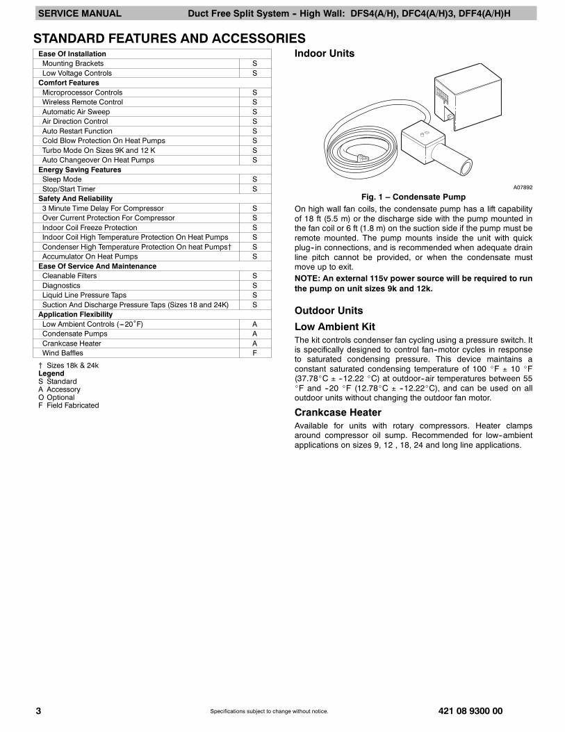
Indoor Units
A07892
Fig. 1 – Condensate PumpOn high wall fan coils, the condensate pump has a lift capabilityof 18 ft (5.5 m) or the discharge side with the pump mounted inthe fan coil or 6 ft (1.8 m) on the suction side if the pump must beremote mounted. The pump mounts inside the unit with quickplug--in connections, and is recommended when adequate drainline pitch cannot be provided, or when the condensate mustmove up to exit.NOTE: An external 115v power source will be required to runthe pump on unit sizes 9k and 12k.
Outdoor Units
Low Ambient KitThe kit controls condenser fan cycling using a pressure switch. Itis specifically designed to control fan--motor cycles in responseto saturated condensing pressure. This device maintains aconstant saturated condensing temperature of 100 _F ± 10 _F(37.78_C ± --12.22 _C) at outdoor--air temperatures between 55_F and --20 _F (12.78_C ± --12.22_C), and can be used on alloutdoor units without changing the outdoor fan motor.
Crankcase HeaterAvailable for units with rotary compressors. Heater clampsaround compressor oil sump. Recommended for low--ambientapplications on sizes 9, 12 , 18, 24 and long line applications.
SERVICE MANUAL Duct Free Split System -- High Wall: DFS4(A/H), DFC4(A/H)3, DFF4(A/H)H
421 08 9300 00 4Specifications subject to change without notice.
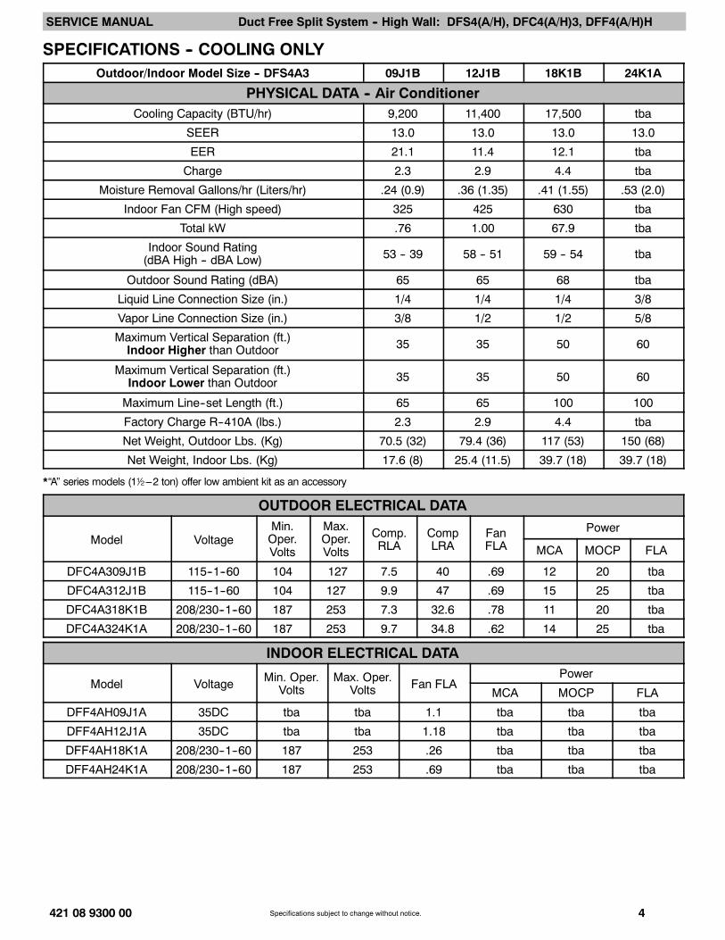
SPECIFICATIONS -- COOLING ONLYOutdoor/Indoor Model Size -- DFS4A3 09J1B 12J1B 18K1B 24K1A
PHYSICAL DATA -- Air ConditionerCooling Capacity (BTU/hr) 9,200 11,400 17,500 tba
SEER 13.0 13.0 13.0 13.0
EER 21.1 11.4 12.1 tba
Charge 2.3 2.9 4.4 tba
Moisture Removal Gallons/hr (Liters/hr) .24 (0.9) .36 (1.35) .41 (1.55) .53 (2.0)
Indoor Fan CFM (High speed) 325 425 630 tba
Total kW .76 1.00 67.9 tba
Indoor Sound Rating(dBA High -- dBA Low) 53 -- 39 58 -- 51 59 -- 54 tba
Outdoor Sound Rating (dBA) 65 65 68 tba
Liquid Line Connection Size (in.) 1/4 1/4 1/4 3/8
Vapor Line Connection Size (in.) 3/8 1/2 1/2 5/8
Maximum Vertical Separation (ft.)Indoor Higher than Outdoor 35 35 50 60
Maximum Vertical Separation (ft.)Indoor Lower than Outdoor 35 35 50 60
Maximum Line--set Length (ft.) 65 65 100 100
Factory Charge R--410A (lbs.) 2.3 2.9 4.4 tba
Net Weight, Outdoor Lbs. (Kg) 70.5 (32) 79.4 (36) 117 (53) 150 (68)
Net Weight, Indoor Lbs. (Kg) 17.6 (8) 25.4 (11.5) 39.7 (18) 39.7 (18)
*“A” series models (12 ---2 ton) offer low ambient kit as an accessory
OUTDOOR ELECTRICAL DATA
Model VoltageMin.Oper.Volts
Max.Oper.Volts
Comp.RLA
CompLRA
FanFLA
Power
MCA MOCP FLA
DFC4A309J1B 115--1--60 104 127 7.5 40 .69 12 20 tba
DFC4A312J1B 115--1--60 104 127 9.9 47 .69 15 25 tba
DFC4A318K1B 208/230--1--60 187 253 7.3 32.6 .78 11 20 tba
DFC4A324K1A 208/230--1--60 187 253 9.7 34.8 .62 14 25 tba
INDOOR ELECTRICAL DATA
Model Voltage Min. Oper.Volts
Max. Oper.Volts Fan FLA
Power
MCA MOCP FLA
DFF4AH09J1A 35DC tba tba 1.1 tba tba tba
DFF4AH12J1A 35DC tba tba 1.18 tba tba tba
DFF4AH18K1A 208/230--1--60 187 253 .26 tba tba tba
DFF4AH24K1A 208/230--1--60 187 253 .69 tba tba tba

SERVICE MANUAL Duct Free Split System -- High Wall: DFS4(A/H), DFC4(A/H)3, DFF4(A/H)H
5 421 08 9300 00Specifications subject to change without notice.
SPECIFICATIONS -- HEAT PUMP ONLYOutdoor/Indoor Model Size -- DFS4H3 09J1B 12J1B 18K1B 24K1A
PHYSICAL DATA -- Heat PumpCooling Capacity (BTU/hr) 9,600 11,500 17,500 tba
SEER 13.0 13.0 13.0 13.0
EER 12.1 12.1 11.8 tba
Charge 2.35 3.0 4.5 tba
High Heat Capacity (BTU/hr) 9,400 11,500 17,100 tba
High Heat COP 3.6 3.5 3.3 tba
High Heat HSPF 7.7 7.7 7.7 tba
Low Heat Capacity (BTU/hr) 5,200 7,500 9,700 tba
Low Heat COP 2.4 2.6 2.2 tba
Moisture Removal Gallons/hr (Liters/hr) .24 (0.9) .36 (1.35) .41 (1.55) .53 (2.0)
Total kW .80 .95 1.48 tba
Indoor Fan CFM (High speed) 325 425 560 tba
Indoor Sound Rating(dBA High -- dBA Low) 52 -- 42 59 -- 51 59 -- 54 tba
Outdoor Sound Rating (dBA) 66 64 tba tba
Liquid Line Connection Size (in.) 1/4 1/4 1/4 3/8
Vapor Line Connection Size (in.) 3/8 1/2 1/2 5/8
Maximum Vertical Separation (ft.)Indoor Higher than Outdoor 35 35 50 60
Maximum Vertical Separation (ft.)Indoor Lower than Outdoor 35 35 50 60
Maximum Line--set Length (ft.) 65 65 100 100
Factory Charge R--410A (lbs.) * 2.4 3.0 tba tba
Net Weight, Outdoor Lbs. (Kg) 72.8 (33) 83.8 (38) 117 (53) 151 (68.5)
Net Weight, Indoor Lbs. (Kg) 17.6 (8) 25.4 (11.5) 39.7 (18) 39.7 (18)
*“A” series models (12 ---2 ton) offer low ambient kit as an accessory
OUTDOOR ELECTRICAL DATA
Model VoltageMin.Oper.Volts
Max.Oper.Volts
Comp.RLA
CompLRA
FanFLA
Power
MCA MOCP FLA
DFC4H309J1B 115--1--60 104 127 7.5 40 .69 12 20 tba
DFC4H312J1B 115--1--60 104 127 9.9 47 .69 15 25 tba
DFC4H318K1B 208/230--1--60 187 253 7.3 32.6 .78 11 20 tba
DFC4H324K1A 208/230--1--60 187 253 9.7 34.8 .62 14 25 tba
INDOOR ELECTRICAL DATA
Model Voltage Min. Oper.Volts
Max. Oper.Volts Fan FLA
Power
MCA MOCP FLA
DFF4HH09J1A 115--1--60 tba tba 1.1 tba tba tba
DFF4HH12J1A 115--1--60 tba tba 1.18 tba tba tba
DFF4HH18K1A 208/230--1--60 187 253 .26 tba tba tba
DFF4HH24K1A 208/230--1--60 187 253 .39 tba tba tba
*“A” series models (12 ---2 ton) offer low ambient kit as an accessory

SERVICE MANUAL Duct Free Split System -- High Wall: DFS4(A/H), DFC4(A/H)3, DFF4(A/H)H
421 08 9300 00 6Specifications subject to change without notice.
DIMENSIONS -- INDOOR
A07336
Model SizeW
in. (mm)H
in. (mm)D
in. (mm) Weight lb (kg)
9K 32.09 (815) 11.02 (280) 7.68 (195) 24.2 (11)
12K 35.67 (906) 11.26 (286) 9.25 (235) 33.0 (15)
18K 49.21 (1250) 12.80 (325) 9.06 (230) 55.0 (25)
24K 49.21 (1250) 12.80 (325) 9.06 (230) 55.0 (25)
DIMENSIONS -- OUTDOOR
L1
L2
35
W
H
Air Flow
L3
A07337
Model SizeW
in. (mm)H
in. (mm)L1
in. (mm)L2
in. (mm)L3
in. (mm)Weight lb (kg)Cooling Only
Weight lb (kg)Heat Pumps
9K 30.71 (780) 21.26 (540) 21.61 (549) 11.81 (300) 10.87 (276) 77.0 (35) 79.2 (36)
12K 29.92 (760) 23.23 (590) 20.87 (530) 12.40 (315) 11.42 (290) 85.8 (39) 90.2 (41)
18K 33.07 (840) 27.36 (695) 22.05 (560) 14.17 (360) 13.19 (335) 125.4 (57) 125.4 (57)
24K 31.16 (893) 33.86 (860) 23.11 (588) 13.98 (355) 13.11 (333) 159.5 (72) 160.6 (73)
SERVICE VALVE LOCATIONS
J K
9K 12K 18K 24K
J
K
J K KJ
A07376a
Service Valve Locations9K
in. (mm)12K
in. (mm)18K
in. (mm)24K
in. (mm)J 3.46 (88) 3.19 (81) 3.46 (88) 4.02 (102)K 3.46 (88) 5.63 (143) 3.62 (92) 6.57 (167)

SERVICE MANUAL Duct Free Split System -- High Wall: DFS4(A/H), DFC4(A/H)3, DFF4(A/H)H
7 421 08 9300 00Specifications subject to change without notice.
CLEARANCES -- INDOOR
6" (0.15m) min.
5"(0.13m)
min.
6'
5"(0.13m)
min.
(1.8m)
A07891
Fig. 2 – Indoor unit clearance
CLEARANCES -- OUTDOOR
A
D B
Air-outlet
Air-inlet
C
E
A07894
Fig. 3 – Outdoor Unit Clearance
UNIT 9k and 12k in. (mm) 18k and 24k in. (mm)A 24 (610) 24 (610)B 24 (610) 36 (914)C 24 (610) 24 (610)D 4 (102) 12 (305)E 12 (305) 12 (305)
SERVICE MANUAL Duct Free Split System -- High Wall: DFS4(A/H), DFC4(A/H)3, DFF4(A/H)H
421 08 9300 00 8Specifications subject to change without notice.
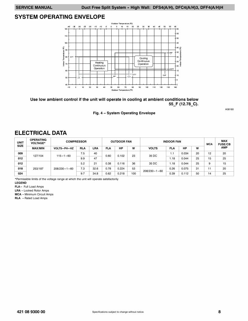
SYSTEM OPERATING ENVELOPE
Use low ambient control if the unit will operate in cooling at ambient conditions below55_F (12.78_C).
A08180
Fig. 4 – System Operating Envelope
ELECTRICAL DATA
UNITSIZE
OPERATINGVOLTAGE* COMPRESSOR OUTDOOR FAN INDOOR FAN
MCAMAX
FUSE/CBAMPMAX/MIN VOLTS---PH---HZ RLA LRA FLA HP W VOLTS FLA HP W
009127/104 115---1---60
7.5 400.60 0.102 23 35 DC
1.1 0.034 20 12 20
012 9.9 47 1.18 0.044 25 15 25
012
253/187 208/230---1---60
5.2 21 0.38 0.116 36 35 DC 1.18 0.044 25 9 15
018 7.3 32.6 0.78 0.224 53208/230---1---60
0.26 0.075 31 11 20
024 9.7 34.8 0.62 0.218 100 0.39 0.112 50 14 25
*Permissible limits of the voltage range at which the unit will operate satisfactorilyLEGENDFLA --- Full Load AmpsLRA --- Locked Rotor AmpsMCA --- Minimum Circuit AmpsRLA --- Rated Load Amps
SERVICE MANUAL Duct Free Split System -- High Wall: DFS4(A/H), DFC4(A/H)3, DFF4(A/H)H
9 421 08 9300 00Specifications subject to change without notice.
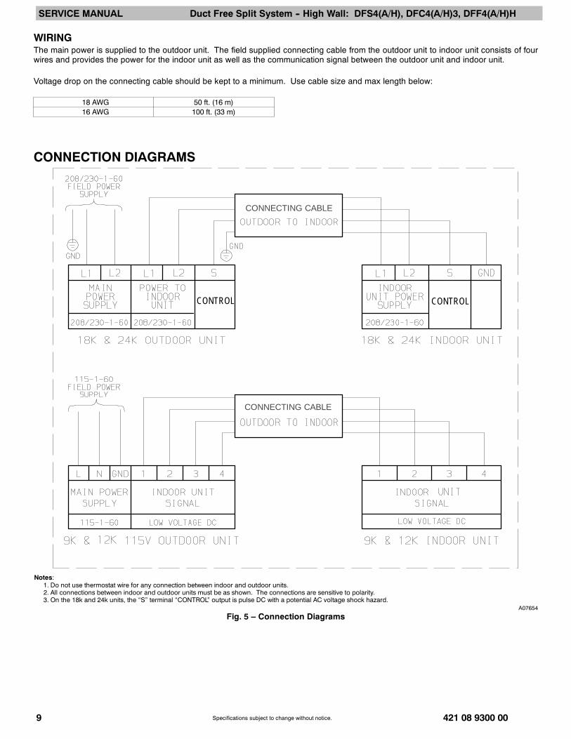
WIRINGThe main power is supplied to the outdoor unit. The field supplied connecting cable from the outdoor unit to indoor unit consists of fourwires and provides the power for the indoor unit as well as the communication signal between the outdoor unit and indoor unit.
Voltage drop on the connecting cable should be kept to a minimum. Use cable size and max length below:
18 AWG 50 ft. (16 m)16 AWG 100 ft. (33 m)
CONNECTION DIAGRAMS
CONNECTING CABLE
CONNECTING CABLE
CONTROL CONTROL
Notes:1. Do not use thermostat wire for any connection between indoor and outdoor units.2. All connections between indoor and outdoor units must be as shown. The connections are sensitive to polarity.3. On the 18k and 24k units, the “S” terminal “CONTROL” output is pulse DC with a potential AC voltage shock hazard.
A07654
Fig. 5 – Connection Diagrams
SERVICE MANUAL Duct Free Split System -- High Wall: DFS4(A/H), DFC4(A/H)3, DFF4(A/H)H
10 421 08 9300 00Specifications subject to change without notice.
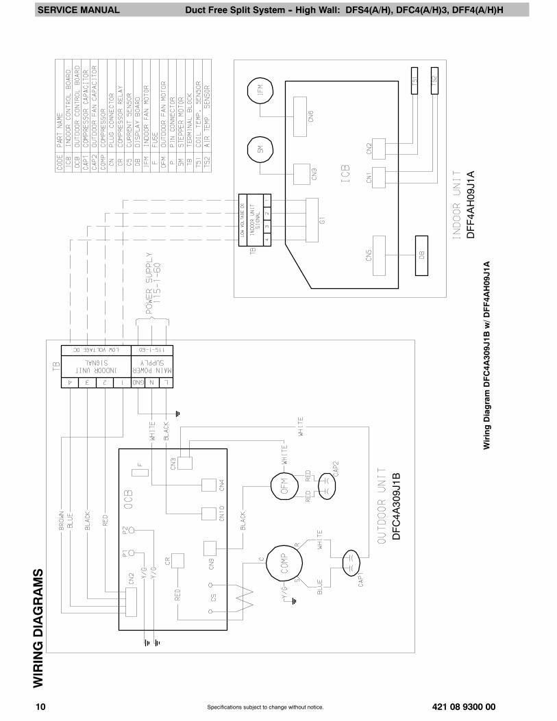
WIRINGDIAGRAMS
DFF4A
H09J1A
DFC4A
309J1B
WiringDiagramDFC4A
309J1B
w/D
FF4A
H09J1A

SERVICE MANUAL Duct Free Split System -- High Wall: DFS4(A/H), DFC4(A/H)3, DFF4(A/H)H
421 08 9300 00 11Specifications subject to change without notice.
WIRINGDIAGRAMS(CONT.)
DFF4A
H12K1A
DFC4A
312K
1B
WiringDiagramDFC4A
312K
1Bw/D
FF4A
H12K1A

SERVICE MANUAL Duct Free Split System -- High Wall: DFS4(A/H), DFC4(A/H)3, DFF4(A/H)H
12 421 08 9300 00Specifications subject to change without notice.
WIRINGDIAGRAMS(CONT.)
DFF4A
H18K1A
DFC4A
318K
1B
WiringDiagramDFC4A
318K
1Bw/D
FF4A
H18K1A
SERVICE MANUAL Duct Free Split System -- High Wall: DFS4(A/H), DFC4(A/H)3, DFF4(A/H)H
421 08 9300 00 13Specifications subject to change without notice.
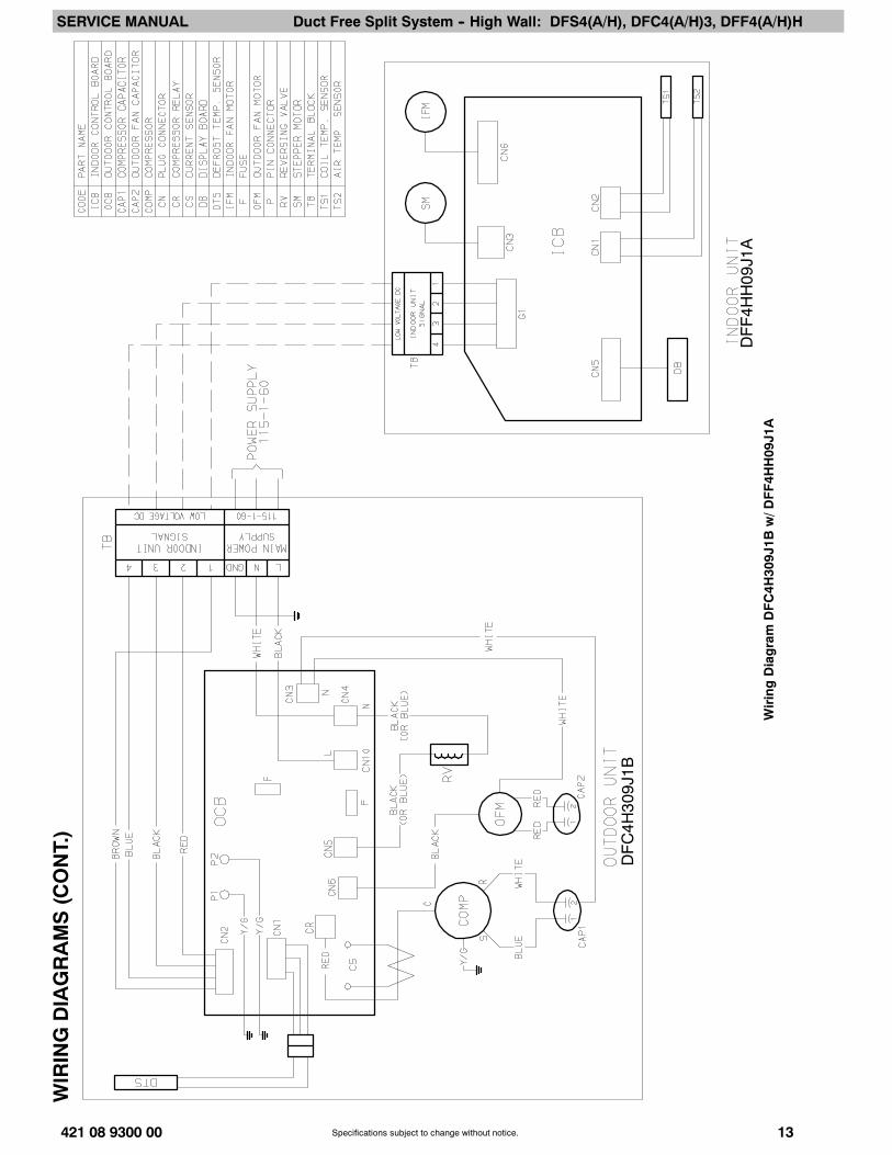
WIRINGDIAGRAMS(CONT.)
DFC4H
309J1B
DFF4H
H09J1A
WiringDiagramDFC4H
309J1B
w/D
FF4H
H09J1A

SERVICE MANUAL Duct Free Split System -- High Wall: DFS4(A/H), DFC4(A/H)3, DFF4(A/H)H
14 421 08 9300 00Specifications subject to change without notice.
WIRINGDIAGRAMS(CONT.)
DFC4H
312K
1B
DFF4H
H12K1A
WiringDiagramDFC4H
312K
1Bw/D
FF4H
H12K1A

SERVICE MANUAL Duct Free Split System -- High Wall: DFS4(A/H), DFC4(A/H)3, DFF4(A/H)H
15 421 08 9300 00Specifications subject to change without notice.
REFRIGERATION CYCLE DIAGRAM
CAPILLARY TUBE
HEATEXCHANGER(CONDENSER)
HEATEXCHANGER(EVAPORATOR)
FIELD PIPING
COMPRESSOR
FLARE CONNECTION
SERVICE VALVE
SERVICE VALVE W/GUAGE PORT
TWO PHASE LIQUID LINE
SUCTION LINE
FIELD PIPING
FLARE CONNECTION
A08104Fig. 6 – Cooling
CAPILLARY TUBE
HEATEXCHANGER(CONDENSER)
HEATEXCHANGER(EVAPORATOR)
SERVICE VALVE
LIQUID HTG LIQUID
TWO PHASECHECK VALVE
(HEATING MODEL ONLY)
REVERSINGVALVE
(HEAT PUMP ONLY)
COOLINGHEATING
COMPRESSOR
SUCTIONDISCHARGE
SUCTION ACCUMULATOR
SERVICE VALVEW/ GUAGE PORT
FIELD PIPING
INDOOR UNIT OUTDOOR UNIT
FLARE CONNECTION
FLARE CONNECTION
A08105Fig. 7 – Heat Pumps

SERVICE MANUAL Duct Free Split System -- High Wall: DFS4(A/H), DFC4(A/H)3, DFF4(A/H)H
421 08 9300 00 16Specifications subject to change without notice.
REFRIGERANT LINESGeneral refrigerant line sizing:
1. The DFC4(A/H) units are shipped with a full charge ofR410A refrigerant. All charges, line sizing, and capacitiesare based on runs of 25 ft (7.6 m). For runs over 25 ft (7.6m), consult long--line section on this page for propercharge adjustments.
2. Minimum refrigerant line length between the indoor andoutdoor units is 10 ft. (3 m).
3. Refrigerant lines should not be buried in the ground. If it isnecessary to bury the lines, not more than 36--in (914 mm)should be buried. Provide a minimum 6--in (152 mm)vertical rise to the service valves to prevent refrigerantmigration.
4. Both lines must be insulated. Use a minimum of 1/2--in.(12.7 mm) thick insulation. Closed--cell insulation isrecommended in all long--line applications.
5. Special consideration should be given to isolatinginterconnecting tubing from the building structure. Isolatethe tubing so that vibration or noise is not transmitted intothe structure.
S The following maximum lengths are allowed:
REFRIGERANT LINE LENGTHS ft. (m)
Unit Size Max Line Length Max Elevation(ID over OD)
Max Elevation(OD over ID)
9K 65 (20) 35 (11) 35 (11)12K 65 (20) 35 (11) 35 (11)18K 100 (30) 50 (15) 50 (15)24K 100 (30) 60 (18) 60 (18)
S The following are the piping sizes.
PIPE SIZESUnit Size Mix Phase Vapor9K 1/4” 3/8”12K 1/4” 1/2”18K 1/4” 1/2”24K 3/8” 5/8”
Refrigerant Charge
REFRIGERANT CHARGE lb. (kg)Unit Size Air Conditioner Heat Pump9K 2.3 (1.0) 2.4 (1.1)12K 2.9 (1.3) 3.0 (1.4)18K 4.4 (2.0) TBD24K TBD TBD
S Above charge is for piping runs up to 25 ft. (7.6 m).S For piping runs greater than 25 ft. (7.6 m), add 0.1 oz. of
refrigerant per foot of extra piping up to the allowablelength.
Long Line Applications, DFC4A Units:1. A crankcase heater should be added for line lengths
longer than 25 ft (7.62 m) to prevent the migration ofrefrigerant to the compressor during the “OFF” cycle.
2. A field fabricated wind baffle is recommended.3. No change in line sizing is required.4. Add refrigerant per table below.
ADDITIONAL CHARGE TABLE
Unit Size
TotalLine Length,
ftAdditional Charge, oz.
Min. Max. 10 --- 25 ft(3.05 --- 7.62m)
>25 --- 65 ft(7.62---19.81m)
>65 --- 100 ft(19.81---30.48m)
9K coolonly
1065
none 0.1 oz perfoot
9K hp
12K coolonly
12K hp
18K coolonly 100 0.1 oz. per
foot
5. Reduction in capacity due to long lines can be calculatedfrom the chart below.
CAPACITY LOSSCapacity, % Loss
Line Length, ftCooling: 25 45 65 1009 & 12 KBTU/H models 0% 2% 5%18 & 24 KBTU/H models 0% 2% 4% 7%Heating:9 & 12 KBTU/H models 0% 7% 11%18 & 24 KBTU/H models 0% 7% 11% 15%

SERVICE MANUAL Duct Free Split System -- High Wall: DFS4(A/H), DFC4(A/H)3, DFF4(A/H)H
17 421 08 9300 00Specifications subject to change without notice.
SYSTEM EVACUATION ANDCHARGING
UNIT DAMAGE HAZARD
Failure to follow this caution may result in equipmentdamage or improper operation.
Never use the system compressor as a vacuumpump.
CAUTION!
Refrigerant tubes and indoor coil should be evacuated using therecommended deep vacuum method of 500 microns. Thealternate triple evacuation method may be used if the procedureoutlined below is followed. Always break a vacuum with drynitrogen.
SYSTEM VACUUM AND CHARGEUsing Vacuum Pump
1. Completely tighten flare nuts A, B, C, D, connect manifoldgage charge hose to a charge port of the low side servicevalve. (See Fig. 15.)
2. Connect charge hose to vacuum pump.3. Fully open the low side of manifold gage. (See Fig. 16)4. Start vacuum pump5. Evacuate using either deep vacuum or triple evacuation
method.6. After evacuation is complete, fully close the low side of
manifold gage and stop operation of vacuum pump.7. The factory charge contained in the outdoor unit is good
for up to 25 ft. (8 m) of line length. For refrigerant lineslonger than 25 ft (8 m), add 0.1 oz. per foot of extra pipingup to the maximum allowable length.
8. Disconnect charge hose from charge connection of thelow side service valve.
9. Fully open service valves B and A.10. Securely tighten caps of service valves.
Outdoor Unit Indoor UnitRefrigerant
Service Valve
Low Side
High Side
A
B
C
D
A07360Fig. 8 – Service Valve
Manifold Gage
500 microns
Low side valve High side valve
Charge hose Charge hose
Vacuum pump
Low side valve
A07361Fig. 9 – Manifold
Deep Vacuum MethodThe deep vacuum method requires a vacuum pump capable ofpulling a vacuum of 500 microns and a vacuum gage capable ofaccurately measuring this vacuum depth. The deep vacuummethod is the most positive way of assuring a system is free ofair and liquid water. (See Fig. 17)
500
MINUTES0 1 2 3 4 5 6 7
10001500
LEAK INSYSTEM
VACUUM TIGHTTOO WET
TIGHTDRY SYSTEM
2000MICRONS
250030003500400045005000
A95424Fig. 10 – Deep Vacuum Graph
Triple Evacuation MethodThe triple evacuation method should only be used when vacuumpump is only capable of pumping down to 28 in. of mercuryvacuum and system does not contain any liquid water.Refer to Fig. 18 and proceed as follows:
1. Pump system down to 28 in. of mercury and allow pumpto continue operating for an additional 15 minutes.
2. Close service valves and shut off vacuum pump.3. Connect a nitrogen cylinder and regulator to system and
open until system pressure is 2 psig.4. Close service valve and allow system to stand for 1 hr.
During this time, dry nitrogen will be able to diffusethroughout the system absorbing moisture.
5. Repeat this procedure as indicated in Fig. 18. System willthen be free of any contaminants and water vapor.
CHECK FOR TIGHT, DRY SYSTEM(IF IT HOLDS DEEP VACUUM)
EVACUATE
BREAK VACUUM WITH DRY NITROGEN
WAIT
EVACUATE
RELEASE CHARGE INTO SYSTEM
BREAK VACUUM WITH DRY NITROGEN
EVACUATE
WAIT
A95425Fig. 11 – Triple Evacuation Method
Final Tubing CheckIMPORTANT: Check to be certain factory tubing on bothindoor and outdoor unit has not shifted during shipment.Ensure tubes are not rubbing against each other or anysheet metal. Pay close attention to feeder tubes, makingsure wire ties on feeder tubes are secure and tight.

SERVICE MANUAL Duct Free Split System -- High Wall: DFS4(A/H), DFC4(A/H)3, DFF4(A/H)H
421 08 9300 00 18Specifications subject to change without notice.
CONTROL SYSTEMThe DFF4 unit is equipped with a microprocessor control to perform two functions:
1. Provide safety for the system2. Control the system and provide optimum levels of comfort and efficiency
The main microprocessor is located on the control board of the fan coil unit (outdoor units have a microprocessor too) with thermistorslocated in the fan coil air inlet and on the indoor coil. Heat pump units have a thermistor on the outdoor coil. These thermistors monitorthe system operation to maintain the unit within acceptable parameters and control the operating mode.
SYSTEM SAFETIES
SafetyCooling Only Heat Pump
09K 12K 18K 24K 09K 12K 18K 24K3 Min Time Delay X X X X X X X X
Over Current Protection On Compressor X X X X X X X XIndoor Coil Freeze Protection X X X X X X X X
Condenser High Temperature Protection X X X XIndoor Evaporator High Temperature X X X X
3 MINUTE TIME DELAYIn order to protect the compressor, there is a 3 minute delay on break even if the control is calling for heating or cooling.
COMPRESSOR OVERCURRENT PROTECTIONOvercurrent protection can result due to any of the following:
S The ambient temperature is to high
S Locked rotor on the compressor
S Blockage in refrigeration circuit (cap tubes, for example)
S Outdoor air is blocked or restrictedThe compressor current is monitored continuously and protection is provided as shown below:
3 sec
5 min
1 sec
NormalIndoor fan: Oncompressor: Onoutdoor fan: On
Outdoor fan off (heating)Indoor fan lowspeed (cooling)
Compressor off(after 5 minutes)
Compressor off(after 3 seconds)
Current down
Current up
A08117Fig. 12 – Compressor Overcurrent Protection
If the compressor is stopped 4 times at the 5 minute limit or 1 time at the 3 second limit, the system will be locked off and the main powerwill have to be reset before the system can be restarted.
Time LimitCompressor Current
DFC4(A/H)309J1B DFC4(A/H)312J1B DFC4(A/H)318K1B DFC4(A/H)324K1B3 SEC 14 A 18 A 14 A 23 A5 MIN 12 A 16A 12 A 21 AI SEC 10.5 A 14 A 11 A 18 ANORMAL 9 A 12.5 A 10 A 16 A

SERVICE MANUAL Duct Free Split System -- High Wall: DFS4(A/H), DFC4(A/H)3, DFF4(A/H)H
19 421 08 9300 00Specifications subject to change without notice.
Indoor Coil Freeze ProtectionThe indoor coil can freeze due to any of the following:S Low system chargeS Reduced indoor airflowS Restricted refrigerant flowS Low ambient temperature (outdoor)S Low load (indoor)In cooling mode, the thermistor located on a return bend of theindoor coil monitors the coil temperature continuously. Any timethe coil temperature drops below the TE5 limit for fiveconsecutive minutes, the compressor and outdoor fan will beswitched off until the coil temperature rises above the TE6 asshown below:
Compressor and outdoorfan off (after 5 mins)
Compressor andoutdorr fan on
EVAP temp. down EVAP temp. up
TE5 TE6T
(Evap Temp.)
A08118Fig. 13 – Indoor Coil Freeze Protection
ParameterCoil Temperature ˚F (˚C)
DFC4(A/H)309J1B
DFC4(A/H)312J1B
DFC4(A/H)318K1B
DFC4(A/H)324K1A
TE5 39 (4) 41 (5) 36 (2) 36 (2)TE6 50 (10) 54 (12) 54 (12) 54 (12)
Condenser High Temperature ProtectionCondenser high temperature can occur due to any of thefollowing conditions:S High outdoor ambientS Outdoor fan blockedS Outdoor coil blockedThe outdoor coil thermistor on a heat pump unit continuouslymonitors the temperature of the outdoor coil. Anytime the coiltemperature exceeds the TE10 limit, the compressor is switchedoff and the outdoor fan continues running to reduce the coiltemperature. When the coil temperature drops below the TE11limit, the compressor is switched back on as shown below:
Compressor on Outdoor fan on
COND temp. down
TE11 TE10 T
COND temp. up
Compressor offOutdoor fan on
A08119Fig. 14 – Condenser High Temp Protection
ParameterCondenser Temp.
˚F (˚C)DFC4(A/H)318K1B DFC4(A/H)324K1B
TE10 149 (63) 158 (70)TE11 131 (55) 149 (65)
Indoor High Temperature ProtectionHigh indoor coil temperature (in heating mode) can occur due toany of the following:S High outdoor ambient temperatureS Indoor fan blockedS Indoor coil blocked (including dirty filters)The indoor coil thermistor on a heat pump unit continuouslymonitors the temperature of the indoor coil during heatingoperation. Anytime the coil temperate exceeds the TE8 limit, theoutdoor fan is switched off. If the coil temperature continues toclimb and exceeds the TE7 limit, the compressor is switched off.When the coil temperature drops below the TE9 limit, thecompressor and outdoor fan are switched back on as shownbelow:
TE9 TE8 TE7 T
T temp. up
Compressor on Fan on
T temp. down
Compressor off Fan off
Compressor onFan off
A08120Fig. 15 – Indoor High Temperature Protection
Parameter Condenser Coil Temp.˚F (˚C)
Parameter DFC4(A/H)309J1B
DFC4(A/H)312J1B
DFC4(A/H)318K1B
DFC4(A/H)324K1A
TE7 140 (60) 140 (60) 145 (63) 145 (63)TE8 129 (54) 129 (54) 129 (54) 129 (54)TE9 118 (48) 118 (48) 122 (50) 122 (50)

SERVICE MANUAL Duct Free Split System -- High Wall: DFS4(A/H), DFC4(A/H)3, DFF4(A/H)H
421 08 9300 00 20Specifications subject to change without notice.
SEQUENCE OF OPERATION
InterfaceA wireless remote control, supplied with the unit, is the interfacebetween the fan coil and the user. The wireless remote controlhas the following characteristics:S Capable of displaying _C and _F with _C being the default
setting. To change the default setting, refer to the Owner’sManual or push the recessed F/C button once using a paperclip or similar object*.
S The remote control setpoint range is from 62_F (17_C) to88_F (30_C) in increments of 2_F (1_C).
S There is a dedicated cooling only and heat pump remotecontrol.
S The wireless remote control has an operating range of 25 ft.(7.62 m).
S The same remote control can be used to control more thanone unit.
S If the remote control is lost, damaged, or the batteries areexhausted, the system can be operated by using the manualbutton (forced Auto) located under the front panel.
Manual button
A07364Fig. 16 – Manual Button Location on Unit
* On units produced during week 12 (2008) and later. Unitsproduced before week 12 have dedicated _C or _F controls.
MODES OF OPERATIONThe units have 5 main operating modes:
1. Fan Only2. Cooling3. Heating (heat pumps only)4. Auto5. Dehumidification (Dry)
The units have 2 other modes (manual operation) that areoperated in unique situations:
1. Auto Forced Mode (Emergency)2. Test Mode
Fan Mode OnlyIn this mode, the system circulates the room air without changingthe room air temperature.Cooling ModeIn this mode, the system cools and dries the room air with thefan running continuously, either at a selected fan speed or Autofan speed. The fan runs even when the compressor cycles off.This feature enhances room comfort and efficiency of thesystem.When the unit is operating in cooling, two sub modes can alsobe selected:
1. Sleep Mode is an energy saving feature that changes theset point automatically.
2. Turbo Mode is a comfort feature on the 9k and 12k unitswhere the set point is reached quickly by having the fanrun on high speed regardless of the speed that has beenselected.
Compressor and Outdoor Fan OperationThe compressor and outdoor fan motor cycle on and off basedon the conditions of the set point and the room temperature asshown below. There is no minimum run time.
T = Room Temperature Ts = Set Point Temperature
Compressor offfan off
Compressor andoutdoor fan on
Room temp. down
0 1.8°F T-Ts
Room temp. up
A08106Fig. 17 – Compressor and Outdoor Fan -- Cooling Mode
Indoor Fan OperationWhen in cooling mode, the fan runs continuously either at thechosen set speed , or in Auto mode, where the speed isdetermined by the microprocessor based on the differencebetween the room temperature and the temperature set point asshown below:
Room temp. upRoom temp. down
T= Room TemperatureTs = Set Point Temperature
9.0 °F7.2 °F1.8 °F T-Ts
Low fan
High fan
Med fan
A08107Fig. 18 – Auto Fan -- Cooling Mode
Sleep ModeWhen in cooling mode, additional energy savings can berealized by selecting the Sleep setting. When the Sleep settingis selected, the temperature set point is adjusted automaticallyas shown below:
Set point
Time (hour)1 2
1.8°F
1.8°F
A08108Fig. 19 – Sleep Mode
The unit will shut off 7 hours after the Sleep Mode is selected.Turbo ModeWhen in cooling mode, selecting Turbo will allow the indoor unitto satisfy the temperature set point as quickly as possible. InTurbo Mode, the indoor fan will shift to high speed and either runcontinuously for 20 minutes or until the user pushes the Turbobutton again, at which point the fan speed will return to theoriginal setting.Heating ModeIn this mode, the system heats the room air with the indoor fanrunning at either the selected speed or on Auto. As in thecooling mode, the indoor fan will run continuously unlessinterrupted by the cold blow algorithm. This algorithm will notallow the fan to run if the indoor coil temperature drops below apreset value.The sleep function can be selected while the unit is running inthe Heating Mode. Defrost is controlled by the on--boardmicroprocessor.
SERVICE MANUAL Duct Free Split System -- High Wall: DFS4(A/H), DFC4(A/H)3, DFF4(A/H)H
21 421 08 9300 00Specifications subject to change without notice.
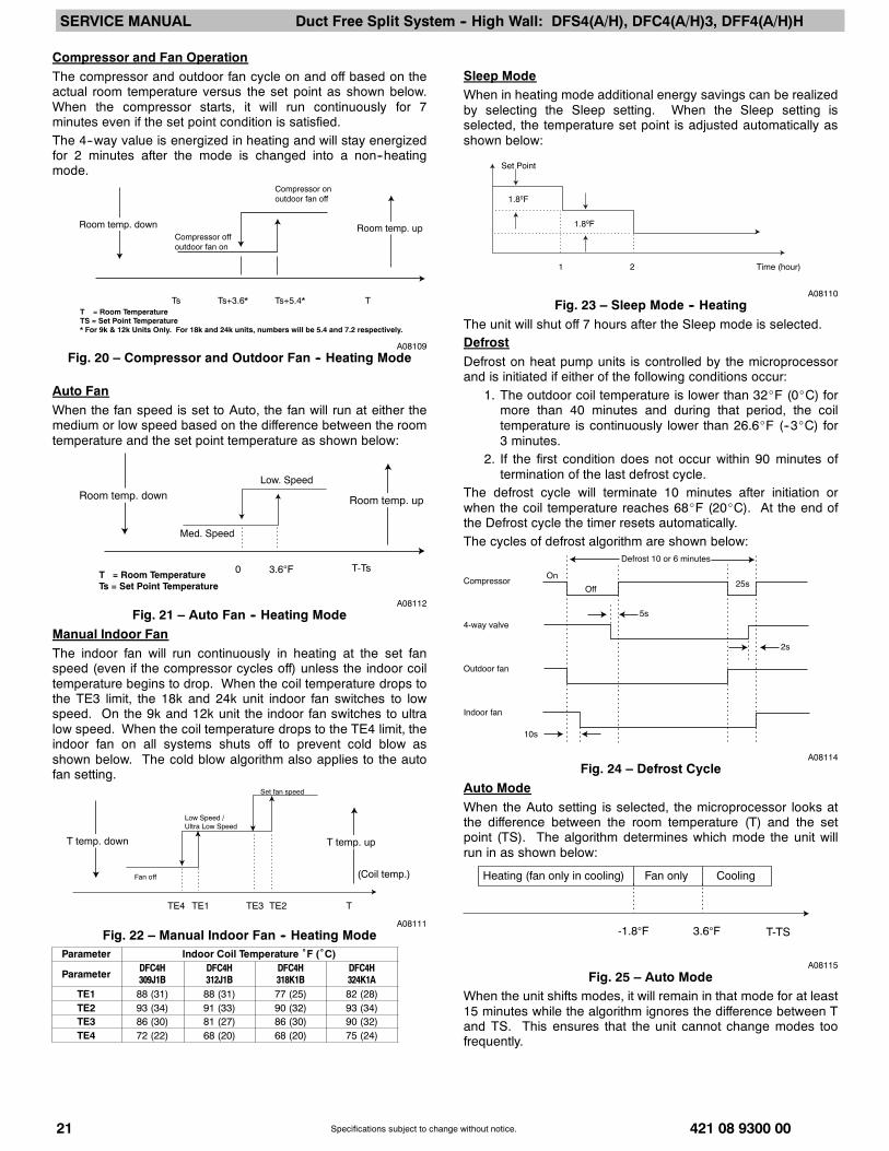
Compressor and Fan OperationThe compressor and outdoor fan cycle on and off based on theactual room temperature versus the set point as shown below.When the compressor starts, it will run continuously for 7minutes even if the set point condition is satisfied.The 4--way value is energized in heating and will stay energizedfor 2 minutes after the mode is changed into a non--heatingmode.
Compressor on outdoor fan off
Room temp. upRoom temp. downCompressor off outdoor fan on
Ts+5.4*Ts+3.6*Ts TT = Room Temperature TS = Set Point Temperature * For 9k & 12k Units Only. For 18k and 24k units, numbers will be 5.4 and 7.2 respectively.
A08109Fig. 20 – Compressor and Outdoor Fan -- Heating Mode
Auto FanWhen the fan speed is set to Auto, the fan will run at either themedium or low speed based on the difference between the roomtemperature and the set point temperature as shown below:
Room temp. upRoom temp. down
T-Ts0
Med. Speed
Low. Speed
3.6°FT = Room Temperature Ts = Set Point Temperature
A08112Fig. 21 – Auto Fan -- Heating Mode
Manual Indoor FanThe indoor fan will run continuously in heating at the set fanspeed (even if the compressor cycles off) unless the indoor coiltemperature begins to drop. When the coil temperature drops tothe TE3 limit, the 18k and 24k unit indoor fan switches to lowspeed. On the 9k and 12k unit the indoor fan switches to ultralow speed. When the coil temperature drops to the TE4 limit, theindoor fan on all systems shuts off to prevent cold blow asshown below. The cold blow algorithm also applies to the autofan setting.
T temp. upT temp. down
Fan off
Low Speed / Ultra Low Speed
Set fan speed
TE4 TE1 TE3 TE2 T
(Coil temp.)
A08111Fig. 22 – Manual Indoor Fan -- Heating Mode
Parameter Indoor Coil Temperature ˚F (˚C)
Parameter DFC4H309J1B
DFC4H312J1B
DFC4H318K1B
DFC4H324K1A
TE1 88 (31) 88 (31) 77 (25) 82 (28)TE2 93 (34) 91 (33) 90 (32) 93 (34)TE3 86 (30) 81 (27) 86 (30) 90 (32)TE4 72 (22) 68 (20) 68 (20) 75 (24)
Sleep ModeWhen in heating mode additional energy savings can be realizedby selecting the Sleep setting. When the Sleep setting isselected, the temperature set point is adjusted automatically asshown below:
Set Point
Time (hour)1 2
1.8ºF
1.8ºF
A08110Fig. 23 – Sleep Mode -- Heating
The unit will shut off 7 hours after the Sleep mode is selected.DefrostDefrost on heat pump units is controlled by the microprocessorand is initiated if either of the following conditions occur:
1. The outdoor coil temperature is lower than 32_F (0_C) formore than 40 minutes and during that period, the coiltemperature is continuously lower than 26.6_F (--3_C) for3 minutes.
2. If the first condition does not occur within 90 minutes oftermination of the last defrost cycle.
The defrost cycle will terminate 10 minutes after initiation orwhen the coil temperature reaches 68_F (20_C). At the end ofthe Defrost cycle the timer resets automatically.The cycles of defrost algorithm are shown below:
Compressor
4-way valve
Outdoor fan
Indoor fan
Defrost 10 or 6 minutes
On
Off
5s
10s
25s
2s
A08114Fig. 24 – Defrost Cycle
Auto ModeWhen the Auto setting is selected, the microprocessor looks atthe difference between the room temperature (T) and the setpoint (TS). The algorithm determines which mode the unit willrun in as shown below:
Heating (fan only in cooling) Fan only Cooling
-1.8°F 3.6°F T-TS
A08115Fig. 25 – Auto Mode
When the unit shifts modes, it will remain in that mode for at least15 minutes while the algorithm ignores the difference between Tand TS. This ensures that the unit cannot change modes toofrequently.

SERVICE MANUAL Duct Free Split System -- High Wall: DFS4(A/H), DFC4(A/H)3, DFF4(A/H)H
421 08 9300 00 22Specifications subject to change without notice.
Dry (Dehumidification) ModeWhen more humidity control is desired, the Dry setting can beselected. Lower humidity is achieved when the microprocessoradjusts the indoor fan speed and compressor cycling bycomparing the room temperature (T) and the set pointtemperature (TS).There are two different control algorithms:Size 9k and 12 k units:T = TS + 3.6 -- the compressor will run for 6 minutes and theindoor fan will run at low speed. The compressor will be off for 4minutes and the indoor fan will run in ultra low speed.TS = T < TS + 3.6 -- The compressor will run for 5 minutes andthe indoor fan will run at low speed. The compressor will be offfor 5 minutes and the indoor fan will run in ultra low speed.T < TS -- The compressor will run for 4 minutes and the indoorfan will run at low speed. The compressor will be off for 6minutes and the indoor fan will run in ultra low speed.Size 18k and 24k units:These units do not have ultra low speed. When set fordehumidification, the indoor fan runs at low speed and thecompressor cycles based on the difference between T and TS.Manual OperationThe unit can be set for Forced Auto or Forced Cooling manuallyby pushing the Manual button once or twice as shown below:
Remotemode
Forcedauto
Forcedcooling
Push 3 Times Push Once Push Twice
A08116Fig. 26 – Manual Operation
Forced Auto (Emergency Operation)Forced Auto option allows operation of the unit if the remotecontrol is lost or the batteries have expired. When the system isin Forced Auto, it will run with a default set point of 75.2_F. Whilein Forced Auto, the system will respond to signals from theremote control.Forced Cooling OperationThis option is used for diagnostic purposes. The system isforced to run in cooling for 30 minutes.After 30 minutes, the 9k and 12k systems will switch to Drymode with a default set point of 75.2_F. The 18k and 24ksystems will switch to Forced Auto mode. When the system is inForced Cooling mode, it will not respond to signals from theremote control. The only way to exit the Forced Cooling mode isto push the manual button once to switch the system to remotecontrol mode.

SERVICE MANUAL Duct Free Split System -- High Wall: DFS4(A/H), DFC4(A/H)3, DFF4(A/H)H
23 421 08 9300 00Specifications subject to change without notice.
TROUBLESHOOTINGThis section provides the required flow charts to troubleshoot problems that may arise.NOTE: Information required in the diagnoses can be found either on the wiring diagrams or in the appendix.
Required Tools:The following tools are needed when diagnosing the units:S Digital multimeterS Screw drivers (Phillips and straight head)S Needle--nose pliers
Recommended Steps1. Refer to the diagnostic hierarchy chart below and determine the problem at hand.2. Go to the chart listed in the diagnostic hierarchy and follow the steps in the chart for the selected problem.
DIAGNOSTIC HIERARCHY
Unit has a problem
Unit displays a
diagnostic codeUnit not running and
no diagnostic codeUnit running but not
optimally
Refer to page ---
appropriate diagnostic chart
Go to chart # 7 Go to chart # 8 & 9
* For EEROM error, replace the indoor microprocessor board
Unit has a problem
Unit displays a
diagnostic codeUnit not running and
no diagnostic codeUnit running but not
optimally
Refer to page A8 & A9
identify error code* and use Go to chart Go to chart #
* For EEROM error, replace the indoor microprocessor board
A08165For the ease of service, the systems are equipped withdiagnostic code display LED’s on both the indoor and outdoorunits. The outdoor diagnostic display is an LED on the outdoorunit board and is limited to very few errors. However, it is usefulin identifying special error codes like a failure of the outdoor coilsensor on heat pumps. The indoor diagnostic display is acombination of flashing LED’s on the display panel on the frontof the unit. If possible always check the diagnostic codesdisplayed on the indoor unit first.The diagnostic codes for the indoor and outdoor units are listedin appendix A8 and A9.Problems may occur that are not covered by a diagnostic code,but are covered by the diagnostic flow charts starting with thediagnostic hierarchy. These problems will be typical airconditioning mechanical or electrical issues that can becorrected using standard air conditioning repair techniques.
For problems requiring measurements at the control boardsplease note the following:
1. Always disconnect the main power.2. When possible check the outdoor board first.3. Start by removing the outdoor unit top cover.4. Reconnect the main power5. Probe the outdoor board inputs and outputs with a digital
multi--meter referring to the wiring diagrams andinput/output charts found in the appendix.
6. Connect the red probe to hot signal and the black probe tothe ground or negative.
7. Note that some of the DC voltage signals are pulse willgive continuously variable readings.
8. If it is necessary to check the indoor unit board you muststart by disconnecting the main power.
9. Next remove the front cover of the unit and then controlbox cover.
10. Carefully remove the indoor board from the control box,place it face up on a plastic surface (not metal).
11. Reconnect the main power and repeat steps 5,6, and 7.12. Disconnect main power before reinstalling board to avoid
shock hazard and board damage.

SERVICE MANUAL Duct Free Split System -- High Wall: DFS4(A/H), DFC4(A/H)3, DFF4(A/H)H
421 08 9300 00 24Specifications subject to change without notice.
CHART 1 -- INDOOR FAN SPEED OUT OF CONTROL
Reset main power and
restart system using remote.
Problem persists?
Replace indoor fan motor
No further action is
required
No
Yes
Check IFM output and input
on indoor board.
Values good?
Yes
Check motor connection.
Connection good?
NoFix connection
Yes
NoReplace indoor board
Reset main power and
restart system using remote.
Problem persists?
Replace indoor fan motor
No further action is
required
No
Yes
Yes
Check motor connection.
Connection good?
NoFix connection
Yes
NoReplace indoor board
A08166
CHART 2 -- TEMPERATURE SENSOR
Reset main power and
restart system using remote.
Problem persists?
Appendix 6
No further action is
required
No
Yes
Check input and output
on indoor or outdoor board.
Yes
Check sensor connector
at ID or OD board
Connection good?
NoFix connection
Yes
NoReplace board
Check sensor resistance.
No
Yes
Yes
No
Yes
No
NoReplace sensor
No
Double check connection,
for corrosion or high
resistance.
YesYes
A08167

SERVICE MANUAL Duct Free Split System -- High Wall: DFS4(A/H), DFC4(A/H)3, DFF4(A/H)H
25 421 08 9300 00Specifications subject to change without notice.
CHART 3 -- COMPRESSOR OVERCURRENT PROTECTION
Is unit running in outdoor
ambient higher than
125 °F?
Beyond operating range
Outdoor coil clean?Clean coil.
Problem persists? Problem solved
Check connections from
OD board. Corrosion, or
high resistance
Outdoor fan Ok?
Connect gauges to unit.
pressures ok?
Check amp draw to
compressor? Values within
range?
Replace outdoor board
Replace compressor
Clean/repair connection
Problem persists?Problem solved
Change outdoor motor
High head, high suction? High head, low suction?
Unit is overcharged.
Reclaim charge and weigh
in correct charge.
Yes
Yes
Yes
Yes
Yes
No
No
No
No No
No
No
Yes
Yes
No
No
Yes
Yes
Restriction in refrigeration
circuit.
A08168
CHART 4 -- INDOOR UNIT COMMUNICATION ERROR SIZE 9K AND 12K
Reset main power and
restart system using remote.
Problem persists?
.
No further action is
required
No
Yes
Measure Volts DC on
outdoor TB between 1 & 3.
Ok?**
Yes
Check the wires and
connections between
Indoor and outdoor units*
No
Fix connection or
replace wiring
No
Yes
Replace outdoor board.
** There is a 2 to 3 minute window to take the measurement before the diagnostic light is on again.
Measure Volts DC on
indoor TB between 1 & 3.
Ok?**
No
Replace indoor board.
Recheck wiring and
connections
Notes:
Before measuring the Volts DC on outdoor TB,
disconnect the field wire on terminal 1.
Before measuring the Volts DC on Indoor TB,
disconnect the field wire on terminal 1.
Have the red probe of the meter on terminal 1
and the black probe on terminal 3. Reconnect
wiring when measurements are complete.
Reset main power and
restart system using remote.
Problem persists?
.
No further action is
required
No
Yes
Measure Volts DC on
outdoor TB between 1 & 3.
Ok?**
Yes
Check the wires and
connections between
Indoor and outdoor units*
No
Fix connection or
replace wiring
No
Yes
Replace outdoor board.
* Make sure wires are connected per connection diagrams. Failing to do that will result in a communication error.
** There is a 2 to 3 minute window to take the measurement before the diagnostic light is on again.
Measure Volts DC on
indoor TB between 1 & 3.
Ok?**
No
Replace indoor board.
Recheck wiring and
connections
Notes:
Before measuring the Volts DC on outdoor TB,
disconnect the field wire on terminal 1.
Before measuring the Volts DC on Indoor TB,
A08181

SERVICE MANUAL Duct Free Split System -- High Wall: DFS4(A/H), DFC4(A/H)3, DFF4(A/H)H
421 08 9300 00 26Specifications subject to change without notice.
CHART 5 -- OUTDOOR UNIT PROTECTS
Suction and head
equal?
Outdoor coil clean?Clean coil. Problem
persists?
Check sensors.
Flow Chart #2
Connect gauges to
unit. Pressures ok?
Check compressor
Normal suction,
high head?
Non condensables
in sys. Pump down
and recharge unit
High head, high
suction?
Unit is overcharged.
Reclaim charge and
weigh in correct charge
High head, low
suction?
Yes
No
No No No
Problem solvedNo No
Yes
Yes
Yes
Yes
Yes Yes Yes
Check application
limits
Check outdoor unit
board. Indicator light
flashing twice?
No
See note below*
* Restriction in system. Check capillary tube, check for moisture, and check for damage to liquid line between indoor and
outdoor units.
A08182
CHART 6 -- INDOOR UNIT COMMUNICATION ERROR SIZE 18K AND 24K
* Make sure wires are connected per connection diagrams i.e. L1 to L1 and L2 to L2. Failing to do that will result in a
communication error.
** There is a 2 to 3 minute window to take measurements before the diagnostic light is on again.
Reset main power and
restart system using remote.
Problem persists?
.
No further action is
required
No
Yes
Measure VDC reading on
outdoor between S and G.
Reading positive? **
Yes
Check the wires and
connections between
Indoor and outdoor units*
No
Fix connection or
replace wiring
Yes
NoReplace outdoor board
Replace indoor board.
Notes:
When unit is operating normally and a DC
voltage reading is taken between the S and
G terminal on the outdoor unit (or indoor
unit) positive and negative readings will
fluctuate between 0 and 24V DC.
If indoor board is bad, only a positive
readings will be registered between
terminals S and G on the outdoor unit. The
reverse will apply if outdoor board is bad
(only negative readings will register).
Above data is obtained by having the red
probe of the meter on the S terminal and
the black probe on the G terminal.
A08183
SERVICE MANUAL Duct Free Split System -- High Wall: DFS4(A/H), DFC4(A/H)3, DFF4(A/H)H
27 421 08 9300 00Specifications subject to change without notice.
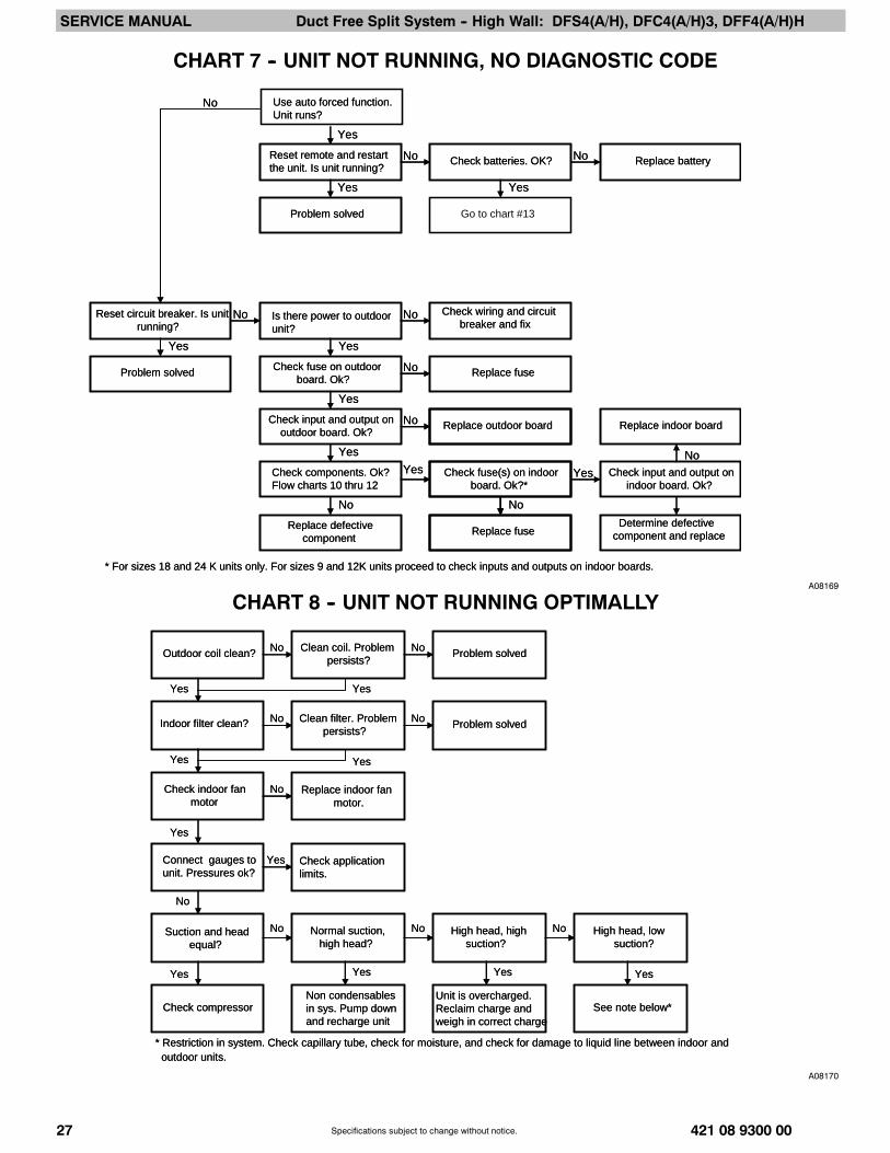
CHART 7 -- UNIT NOT RUNNING, NO DIAGNOSTIC CODE
Yes
Use auto forced function.
Unit runs?
Reset remote and restart
the unit. Is unit running?
Problem solved
Check batteries. OK? Replace battery
Go to chart #13
Reset circuit breaker. Is unit
running?
Yes
Problem solved
Is there power to outdoor
unit?
Yes
Check fuse on outdoor
board. Ok?
Yes
Check input and output on
outdoor board. Ok?
Check components. Ok?
Flow charts 10 thru 12
Yes
No
Replace defective
component
Check wiring and circuit
breaker and fix
Replace fuse
Replace outdoor board
Check fuse(s) on indoor
board. Ok?*
Replace fuse
Replace indoor board
Check input and output on
indoor board. Ok?
Determine defective
component and replace
Yes Yes
Yes Yes
No No
No
No
No
No
No No
No
* For sizes 18 and 24 K units only. For sizes 9 and 12K units proceed to check inputs and outputs on indoor boards.
Yes
Use auto forced function.
Unit runs?
Reset remote and restart
the unit. Is unit running?
Problem solved
Check batteries. OK? Replace battery
Reset circuit breaker. Is unit
running?
Yes
Problem solved
Is there power to outdoor
unit?
Yes
Check fuse on outdoor
board. Ok?
Yes
Check input and output on
outdoor board. Ok?
Check components. Ok?
Flow charts 10 thru 12
Yes
No
Replace defective
component
Check wiring and circuit
breaker and fix
Replace fuse
Replace outdoor board
Check fuse(s) on indoor
board. Ok?*
Replace fuse
Replace indoor board
Check input and output on
indoor board. Ok?
Determine defective
component and replace
Yes Yes
Yes Yes
No No
No
No
No
No
No No
No
* For sizes 18 and 24 K units only. For sizes 9 and 12K units proceed to check inputs and outputs on indoor boards.
A08169
CHART 8 -- UNIT NOT RUNNING OPTIMALLY
Suction and head
equal?
Outdoor coil clean?Clean coil. Problem
persists?
Indoor filter clean?Clean filter. Problem
persists?
Check indoor fan
motor
Connect gauges to
unit. Pressures ok?
Replace indoor fan
motor.
Check compressor
Normal suction,
high head?
High head, high
suction?
Unit is overcharged.
Reclaim charge and
weigh in correct charge
High head, low
suction?
Yes
Yes
Yes
No
No No No
Problem solved
Problem solved
No No
No No
No
Yes
Yes
Yes
Yes
Yes Yes Yes
Check application
limits.
Non condensables
in sys. Pump down
and recharge unit
See note below*
* Restriction in system. Check capillary tube, check for moisture, and check for damage to liquid line between indoor and
outdoor units.
A08170

SERVICE MANUAL Duct Free Split System -- High Wall: DFS4(A/H), DFC4(A/H)3, DFF4(A/H)H
421 08 9300 00 28Specifications subject to change without notice.
CHART 9 -- UNIT NOT RUNNING OPTIMALLY (HP IN HEATING)*
Visually check outdoor
Unit for ice blockage. **
Check reversing valve.
Go to flow chart #12
No
Yes
Yes
Check defrost sensor. Ok? NoReplace sensor
Check application limits.
Ok?
** Check for blockage on outdoor coil and drain pan. Are the holes in drain pans blocked?
NoBeyond operating range
Yes
Yes
Check ambient conditions.
Prime icing?
Explain to customer
Visually check outdoor
Unit for ice blockage. **
Check reversing valve.No
Yes
Yes
Check defrost sensor. Ok?Go to flow chart #2
NoReplace sensor
Check application limits.
Ok?
* To supplement flow chart #8es in drain pans blocked?
NoBeyond operating range
Yes
Yes
Check ambient conditions.
Prime icing?
Explain to customer
A08184
CHART 10 -- COMPRESSOR
Check contactor output on outdoor board if not done already.
If bad, replace outdoor board.
* For size 9 and 12k units contactor is on outdoor board.
Trace connections from
OD board. Connections
ok?
Check compressor
windings. Ok?
No fix connectionNo
Yes
Check capacitor.
Capacitor ok?
Yes
Check contactor.*
Contactor ok?
NoReplace contactor
Yes
NoReplace capacitor
NoReplace compressor
No
Compressor ok.
Trace connections from
OD board. Connections
ok?
Check compressor
windings. Ok?
No fix connectionNo
Yes
Check capacitor.
Capacitor ok?
Yes
Check contactor.*
Contactor ok?
NoReplace contactor
Yes
NoReplace capacitor
NoReplace compressor
No
Compressor ok.
A08171
SERVICE MANUAL Duct Free Split System -- High Wall: DFS4(A/H), DFC4(A/H)3, DFF4(A/H)H
29 421 08 9300 00Specifications subject to change without notice.
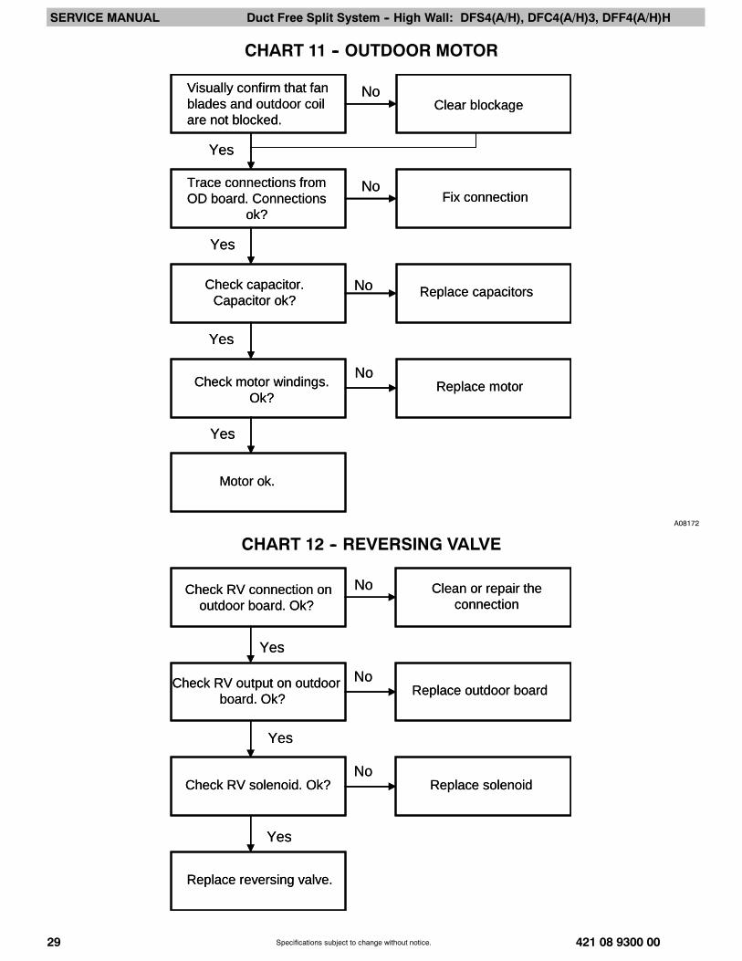
CHART 11 -- OUTDOOR MOTOR
Trace connections from
OD board. Connections
ok?
Motor ok.
Fix connectionNo
Yes
Yes
No
Replace capacitors
Yes
No
Replace motor
Check capacitor.
Capacitor ok?
Check motor windings.
Ok?
Visually confirm that fan
blades and outdoor coil
are not blocked. Clear blockage
Yes
No
Trace connections from
OD board. Connections
ok?
Motor ok.
Fix connectionNo
Yes
Yes
No
Replace capacitors
Yes
No
Replace motor
Check capacitor.
Capacitor ok?
Check motor windings.
Ok?
Visually confirm that fan
blades and outdoor coil
are not blocked. Clear blockage
Yes
No
A08172
CHART 12 -- REVERSING VALVE
Check RV connection on
outdoor board. Ok?
Clean or repair the
connection
No
Yes
Yes
Check RV output on outdoor
board. Ok?
NoReplace outdoor board
Replace reversing valve.
Yes
Check RV solenoid. Ok? Replace solenoidNo
Check RV connection on
outdoor board. Ok?
Clean or repair the
connection
No
Yes
Yes
Check RV output on outdoor
board. Ok?
NoReplace outdoor board
Replace reversing valve.
Yes
Check RV solenoid. Ok? Replace solenoidNo
SERVICE MANUAL Duct Free Split System -- High Wall: DFS4(A/H), DFC4(A/H)3, DFF4(A/H)H
421 08 9300 00 30Specifications subject to change without notice.
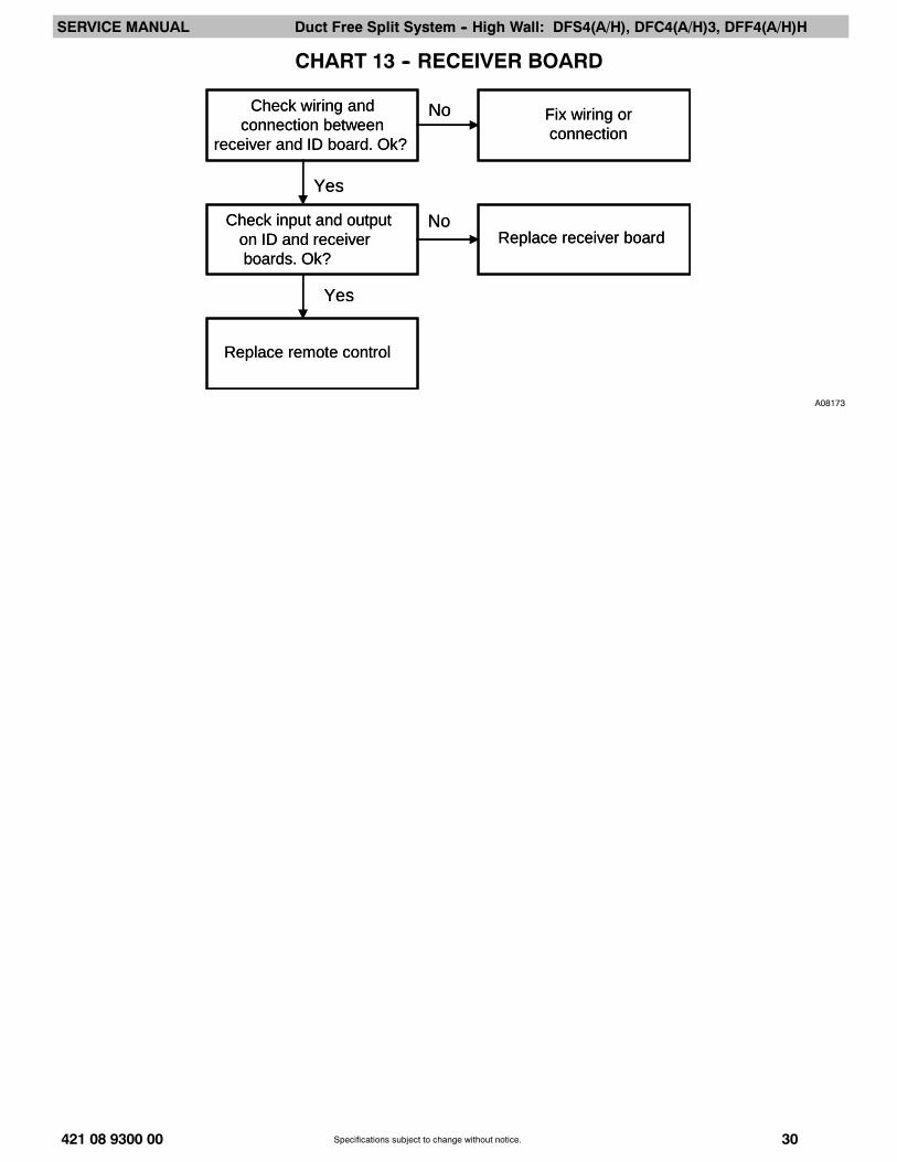
CHART 13 -- RECEIVER BOARD
Check wiring and
connection between
receiver and ID board. Ok?
Fix wiring or
connection
No
Yes
Replace remote control
Yes
Check input and output
on ID and receiver
boards. Ok?
NoReplace receiver board
Check wiring and
connection between
receiver and ID board. Ok?
Fix wiring or
connection
No
Yes
Replace remote control
Yes
Check input and output
on ID and receiver
boards. Ok?
NoReplace receiver board
A08173

SERVICE MANUAL Duct Free Split System -- High Wall: DFS4(A/H), DFC4(A/H)3, DFF4(A/H)H
31 421 08 9300 00Specifications subject to change without notice.
A1 -- DFS4A309J1B/DFS4A312J1B
DFC4A309J1B/DFC4A312J1B CONTROL BOARD
CONNECTOR INPUT or OUTPUT VALUE
CN2 OUT: (Pin 1: Pulse 0 to 12 Volts DC) (Pin2: 35±2 Volts DC) (Pin 3: GND) (Pin 4: 13±4 Volts DC) all relative to Pin 3
CN3 OUT: Neutral
CN4 IN: Neutral
CN9 OUT: L 115 Volts AC
CN10 IN: L 115 Volts AC
P1 GND
P2 GND
DFF4AH09J1A/DFF4AH12J1A CONTROL BOARD
CONNECTOR INPUT or OUTPUT VALUE
CN1 IN: 0---5 Volt DC
CN2 IN: 0---5 Volt DC
CN3 Pulse drive output: 0---17 Volts DC(Pin 5: GND All other Pins are 0 to 17 Volt DC) All relative to Pin 5)
CN5 Power Output: (Pin 1: GND) (Pin 2: 5 Volts DC) Input: (Pin 3: Pulse 0 to 5 Volts DC) Output:(Pin 4~Pin 10: Pulse 0 to 5 Volt DC)All relative to Pin 1
CN6 Out: (Pin 1: 35 Volt DC) ( Pin 2: Empty) (Pin 3: GND) (Pin 4: 5 Volt DC) (Pin 5: Pulse 0---5 Volt DC) IN: (Pin 6: Pulse 0 to 5 Volt DC)All relative to Pin 3
G1 IN: (Pin 1: Pulse 0 to 12 Volts DC) (Pin2: 35±2 Volts DC) (Pin 3: GND) (Pin 4: 13±4 Volts DC) all relative to Pin 3
A2 -- DFS4H309J1B/DFS4H312J1BDFC4H309J1B/DFC4H312J1B CONTROL BOARD
CONNECTOR INPUT or OUTPUT VALUE
CN1 OUT: (Pin 1: GND, Pin 2: 5 Volts DC, Pin 3: Empty) IN: (Pin 4: 0 to 5 Volts DC) All relative to Pin 1
CN2 OUT: (Pin 1: Pulse 0 to 12 Volts DC) (Pin2: 35±2 Volts DC) (Pin 3: GND) (Pin 4: 13±4 Volts DC) all relative to Pin 3
CN3 OUT: Neutral
CN4 IN: Neutral
CN5 OUT: L 115 Volt AC
CN6 OUT: L 115 Volt AC
CN10 IN: L 115 Volt AC
P1 GND
P2 GND
DFF4HH09J1A/DFF4HH12J1A CONTROL BOARD
CONNECTOR INPUT or OUTPUT VALUE
CN1 IN: 0---5 Volt DC
CN2 IN: 0---5 Volt DC
CN3 Pulse drive output: 0---17 Volts DC(Pin 5: GND All other Pins are 0 to 17 Volt DC) All relative to Pin 5)
CN5 Power Output: (Pin 1: GND) (Pin 2: 5 Volts DC) Input: (Pin 3: Pulse 0 to 5 Volts DC) Output:(Pin 4~Pin 10: Pulse 0 to 5Volt DC) All relative to Pin 1
CN6 Out: (Pin 1: 35 Volt DC) ( Pin 2: Empty) (Pin 3: GND) (Pin 4: 5 Volt DC) (Pin 5: Pulse 0---5 Volt DC) IN: (Pin 6: Pulse 0 to 5Volt DC) All relative to Pin 3
G1 IN: (Pin 1: Pulse 0 to 12 Volts DC) (Pin2: 35±2 Volts DC) (Pin 3: GND) (Pin 4: 13±4 Volts DC) all relative to Pin 3

SERVICE MANUAL Duct Free Split System -- High Wall: DFS4(A/H), DFC4(A/H)3, DFF4(A/H)H
421 08 9300 00 32Specifications subject to change without notice.
A5 -- DFS4A318K1B
DFC4A318K1B CONTROL BOARD
CONNECTOR INPUT or OUTPUT VALUE
CN1 IN: 14.5±5V Volts AC
CN3 Pulse Signal 0 to 24 Volts DC (Relative to ground)
CN4 IN: L1 208/230 Volts AC
CN5 IN: L2 208/230 Volts AC
CN6 OUT: 208/230 Volts AC
CN8 OUT: 208/230 Volts AC
DFF4AH18K1A CONTROL BOARD
CONNECTOR INPUT or OUTPUT VALUE
CN1 IN: 11.0±3 Volts AC (Pin 1 to Pin2 ); 9.5±2 Volts AC (Pin 3 to Pin 4)
CN2 OUT: IFM Capacitor Terminal 1
CN4 OUT: IFM Capacitor Terminal 2
CN5 OUT: 208/230 Volts AC
CN6 OUT: 208/230 Volts AC (Pin 1 to Pin 2, Pin 1 to Pin 3, Pin 1 to Pin4)
CN7 IN: 0---5 Volt DC (Not including 0V and 5V)
CN8 IN: 0---5 Volt DC (Not including 0V and 5V)
CN9 OUT: (Pin 1: Ground, Pin 2: 5 Volts DC) IN: (Pin 1: Ground, Pin 3: 0 to 5 Volts DC) Pulse relative to Pin 1
CN10 OUT: (Pin 1: Ground, Pin 2 ~ Pin 5: 0 to 5 Volts DC) Pulse relative to Pin 1
CN11 OUT: (Pin 5: Ground, all other Pins are 0 to 17 Volts DC) Pulse relative to Pin 5
CN12 Two way signal, 0 to 24 Volts DC, Pulse relative to Ground
P1 IN: L1 208/230 Volts AC
P2 IN: L2 208/230 Volts AC
INDOOR UNIT DISPLAY BOARD
CONNECTOR INPUT or OUTPUT VALUE
CN1 IN: (Pin 1: Ground, Pin 2 ~ 5: 0 to 5 Volts DC) Pulse relative to Pin 1
CN2 IN: (Pin 1: Ground, Pin: 5 Volts DC) OUT: (Pin 3: 0 to 5 Volts DC) Pulse relative to Pin 1

SERVICE MANUAL Duct Free Split System -- High Wall: DFS4(A/H), DFC4(A/H)3, DFF4(A/H)H
33 421 08 9300 00Specifications subject to change without notice.
A6 -- Characteristics of Temperature Sensor
Temp. ˚F/˚C Resistance KΩ Temp. ˚F/˚C Resistance KΩ Temp. ˚F/˚C Resistance KΩ14/---10 62.2756 62.6/17 14.6181 111.2/44 4.387415.8/---9 58.7079 64.4/18 13.918 113/45 4.212617.6/---80 56.3694 66.2/19 13.2631 114.8/46 4.045919.4/---7 52.2438 68/20 12.6431 116.6/47 3.886721.2/---6 49.3161 69.8/21 12.056 118.4/48 3.734823/---5 46.5725 71.6/22 11.5 120.2/49 3.589624.8/---4 44 73.4/23 10.9731 122/50 3.45126.6/---3 41.5878 75.2/24 10.4736 123.8/51 3.318528.4/---2 39.8239 77/25 10 125.6/52 3.191830.2/---1 37.1988 78.8/26 9.5507 127.4/53 3.070732/0 35.2024 80.6/27 9.1245 129.2/54 2.95933.8/1 33.3269 82.4/28 8.7198 131/55 2.844235.6/2 31.5635 84.2/29 8.3357 132.8/56 2.738237.4/3 29.9058 86/30 7.9708 134.6/57 2.636839.2/4 28.3459 87.8/31 7.6241 136.4/58 2.539741/5 26.8778 89.6/32 7.2946 138.2/59 2.446842.8/6 25.4954 91.4/33 6.9814 140/60 2.357744.6/7 24.1932 93.2/34 6.6835 141.8/61 2.272546.4/8 22.5662 95/35 6.4002 143.6/62 2.190748.2/9 21.8094 96.8/36 6.1306 145.4/63 2.112450/10 20.7184 98.6/37 5.8736 147.2/64 2.037351.8/11 19.6891 100.4/38 5.6296 149/65 1.965353.6/12 18.7177 102.2/39 5.3969 150.8/66 1.896355.4/13 17.8005 104/40 5.1752 152.6/67 1.8357.2/14 16.9341 105.8/41 4.9639 154.4/68 1.766559/15 16.1156 107.6/42 4.7625 156.2/69 1.705560.8/16 15.3418 109.4/43 4.5705 158/70 1.6469
A7 -- Fuse Chart
Unit SizeFuse Rating (Amps/Volts)
Indoor Outdoor Outdoor009 --- 3.15A/250V 2A/250V012 --- 3.15A/250V 2A/250V018 3.15A/250V 3.15A/250V ---024 3.15A/250V 3.15A/250V ---
The 3.15A fuses protect the board against the indoor or outdoor fan motors.The 2A fuses protect the board against a Class II circuit board failure.
SERVICE MANUAL Duct Free Split System -- High Wall: DFS4(A/H), DFC4(A/H)3, DFF4(A/H)H
421 08 9300 00 34Specifications subject to change without notice.
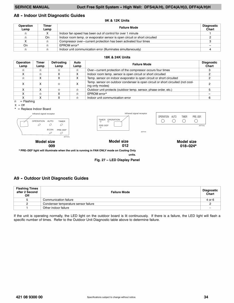
A8 -- Indoor Unit Diagnostic Guides9K & 12K Units
OperationLamp
TimerLamp Failure Mode Diagnostic
Chartl X Indoor fan speed has been out of control for over 1 minute 1l On Indoor room temp. or evaporator sensor is open circuit or short circuited 2X l Compressor over---current protection has been activated four times 3On l EPROM error* ---l l Indoor unit communication error (Illuminates simultaneously) 4
18K & 24K UnitsOperationLamp
TimerLamp
DefrostingLamp
AutoLamp Failure Mode Diagnostic
Chartl l l l Over---current protection of the compressor occurs four times 3X l X X Indoor room temp. sensor is open circuit or short circuited 2l X X X Temp. sensor on indoor evaporator is open circuit or short circuited 2
X X l X Temp. sensor on outdoor condenser is open circuit or short circuited (not cool-ing only modes) 2
X X l l Outdoor unit protects (outdoor temp. sensor, phase order, etc.) 5X l X l EPROM error* ---X X X l Indoor unit communication error 6
l = FlashingX = Off* = Replace Indoor Board
A07545a
A07544
A07546a
Model size009
Model size012
Model size018--024*
Infrared signal receptor
OPERATION TIMER
PRE-DEF
AUTO
ECON
TIMER OPERATION
PRE-DEF
Infrared signal receptor
* PRE--DEF light will illuminate when the unit is running in FAN ONLY mode on Cooling Only
units.
AUTO TIMER PRE.-DEF.OPERATION
Fig. 27 – LED Display Panel
A9 -- Outdoor Unit Diagnostic Guides
Flashing Timesafter 2 Second
OffFailure Mode Diagnostic
Chart
5 Communication failure 4 or 62 Condenser temperature sensor failure 21 Other indoor failure –
If the unit is operating normally, the LED light on the outdoor board is lit continuously. If there is a failure, the LED light will flash aspecific number of times. Refer to the Outdoor Unit Diagnostic table above to determine failure.