Aymond Citation Petition Original Complete Served November 2009
Upload
tomas-merkeviciusCategory
view
411download
12
SEI Volume 20 | Number 4 | November 2010
STRUCTURAL ENGINEERING INTERNATIONAL
International Association for Bridge and Structural Engineering (IABSE)
Fibre Reinforced Polymer Composites
sei_4-10OFC.indd 1sei_4-10OFC.indd 1 20/10/10 4:38 PM20/10/10 4:38 PM

Bridge Information Modeling is a compelling new methodology for project delivery that dramatically improves bridge quality and reduces risk. Using the Bentley bridge solution for BrIM, engineers develop and employ an unprecedented depth of information about the bridge as they streamline the entire bridge development process, design through construction engineering.
Organizations achieve the highest level of real-time team collaboration using the Bentley solution. They get the right information in the right hands and ultimately empower project stakeholders to collectively deliver the best-quality, most constructible bridges possible. They also deliver an invaluable bridge information asset to the owner for lifetime operation of the bridge.
With our leading bridge design and engineering systems, RM Bridge and LEAP Bridge, projects evolve in a synthesis of modeling, analysis, and design. Engineers perform an array of intensive analyses of any condition, from seismic impact to wind dynamics and even rolling stock analysis – for every stage of construction.
Join the world’s top engineering consultancies. Choose the Bentley bridge solution for BrIM – and the satisfaction of delivering safe, sustainable bridges on time and on budget.
Only Bentley can take you there. www.bentley.com/SEI
© 2010 Bentley Systems, Incorporated. Bentley, the “B” Bentley logo, and LEAP are either registered or unregistered trademarks or service marks of Bentley Systems, Incorporated or one of its direct or indirect wholly-owned subsidiaries. Other brands and product names are trademarks of their respective owners.
Bridge Information Modeling – It’s everything to do with the bridge.
5828_Ad_STI-Bridge_A4-SEI_0610.indd 1 28-6-2010 19:24:08

structural bearingsexpansion joints Switzerland www.mageba.ch
bridges - linking people®
Bandra Worli Sea Link, IndiaEquipped with 254 DISKTRON disc bearings (Vmax =
14,000 kN) and 26 mageba TENSA®MODULAR expansion joints of types LR2 to LR6 (max. movement: 480mm).
Hong Kong
Croatia Finland
South Korea
Germany
Portugal Slovenia
Canada FranceDenmark
Poland Switzerland
China
USA
seismic devicesmonitoring & services
p1.indd 1p1.indd 1 2/1/10 10:04:13 AM2/1/10 10:04:13 AM

s i n c e 1 9 1 0
Innovat ion & Consistency
Sika’s Advanced Technologiesfor Bridge EngineeringSika® ViscoCrete®
High performance concretes using
Sika® ViscoCrete® Admixture
TechnologySelf compactingFast /Controlled settingWatertight and corrosion resistant
Sika Services AG
Business Unit ConstractorsCH-8330 PfäffikonSwitzerlandPhone +41 58 436 23 79Fax: +41 58 436 23 77www.sika.com
SikaGrout®
Long lasting cable ducts using
SikaGrout® PT-Technology
Factory quality controlledWaterproofCorrosion resistant
Sika® CarboDur®
Structural strengthening using
Sika® CarboDur® Technology
CFRP plate systemsFabric systemsPatented prestressing systemsCarboShear® system
p2.indd 1p2.indd 1 1/22/10 10:41:34 PM1/22/10 10:41:34 PM

Structural Engineering International 4/2010 359
Information on SEIwww.iabse.org/sei
SEI Advisory BoardJ.-E. Breen, W.F. Chen, Y. Fujino, N.J. Gimsing, P.R. Head, M. A. Hirt, D.A. Nethercot, M.J. Priestley, J. Schlaich, P. Taylor, M. Virlogeux, J.C. Walraven, H.F. Xiang.
SEI Editorial BoardH.H. Snijder, Chair; A. Schumacher, Vice Chair; M.G. Bruschi, A. Frangi, N.P. Hoej, K. Sugiura, D.Xu
CorrespondentsChina: D. Xu. Denmark: M. Braestrup.Egypt: F. Saad. Finland:M.-K. Söderqvist. France: B. Godart.Germany: U. Kuhlmann. India: V. Kumar.Italy: G. Bignotti, L. Ceriolo.Japan: K. Fujita. Korea: H.K. Kim.Norway: L. Toverud. Poland: W. Radomski.Russia: S.V. Mozalev. Sweden:H. Sundquist. Thailand: E. Limsuwan.UK: D.K. Doran. USA: J. Burns,D. Frangopol.
PublisherIABSEETH Zurich8093 Zurich, SwitzerlandTel: 41-44-633 2647Fax: 41-44-633 [email protected]
Publications ManagerBrindarica Bose, IABSE
Advertising InquiriesSissel Niggeler, IABSE
PublishedQuarterly: 1 Feb., 1 May, 1 Aug., 1 Nov.
Subscription 2011Included in IABSE Membership.220 CHF: Individual Subscription630 CHF: Institutional SubscriptionAvailable through subscription agencies.
ISSN 1016-8664, E-ISSN 1683-0350Copyright © IABSE. All rights reserved.Opinions and positions expressed in signed articles are those of the authors and are not necessarily those of Structural Engineering International or IABSE.
Front cover:Wolchul Mountain Bridge, Korea
See article on page 405
Contents 4/2010 Structural Engineering International International Association for Bridge and Structural Engineering
Abstracting and Indexing: This publication is abstracted in Cambridge Scientific Abstracts under CSA Civil Engineering Abstracts; Emerald Abstracts; Construction and Building Abstracts (CBA); CAB Abstracts; INSPEC; and is included in EBSCOhost and SwetsWise Online Content. For SEI content Photocopying, Electronic usage, in the USA: Contact Copyrights Clearance Centre (CCC) at www.copyrights.com In rest of the world: Contact IABSE, at [email protected]
EditorialStrengthening IABSE; P. L. Popovic; USA 361
Special Feature: Fibre Reinforced Polymer Composites
Scientific Papers*Introduction: Fiber Reinforced Polymer (FRP) Composites; A. Schumacher; Switzerland,
M. D. G. Pulido; Spain 362Glass Fibre Reinforced Polymer Pultruded Flexural Members: Assessment of Existing
Design Methods; J. R. Correia, F. Branco, J. Gonilha, N. Silva, D. Camotim; Portugal 362Effects of Hygrothermal Ageing on the Mechanical Properties of Glass-Fibre-Reinforced
Polymer Pultruded Profiles; J. R. Correia, S. Cabral-Fonseca, A. Carreiro, R. Costa, M. P. Rodrigues, I. Eusébio, F. Branco; Portugal 370
Evaluation of a Life Prediction Model and Environmental Effects of Fatigue for Glass Fiber Composite Materials; D. B. Dittenber, G. V. S. Hota; USA 379
A Composite Bridge is Favoured by Quantifying Ecological Impact; R. A. Daniel; The Netherlands 385Experimental Assessment of Bond Behaviour of Fibre-Reinforced Polymers on Brick Masonry;
E. Garbin, M. Panizza, M. Valluzzi; Italy 392Bridges with Glass Fibre–Reinforced Polymer Decks: The Road Bridge in Friedberg, Germany;
J. Knippers, E. Pelke, M. Gabler, D. Berger; Germany 400
Technical ReportsCurrent and Future Applications of Glass-Fibre-Reinforced Polymer Decks in Korea; S. W. Lee,
K. J. Hong, S. Park; Korea 405Field Issues Associated with the Use of Fiber-Reinforced Polymer Composite Bridge Decks
and Superstructures in Harsh Environments; L. N. Triandafilou, J. S. O’Connor; USA 409Examples of Applications of Fibre Reinforced Plastic Materials in Infrastructure in Spain;
A. Bansal, J. F. M. Cano, B. O. O. Muñoz, C. Paulotto; Spain 414Fiber-Reinforced Polymer Decks for Movable Bridges; R. D. Bottenberg; USA 418Glass Fiber Reinforced Polymer Strengthening and Evaluation of Railroad Bridge Members;
G. V. S. Hota, P. V. Vijay, R. S. Abhari; USA 423Design of the St Austell Fibre-Reinforced Polymer Footbridge, UK; J. Shave, S. Denton,
I. Frostick; UK 427
General
Scientific Papers*Aluminium Structures in Building and Civil Engineering Applications; F. Soetens; The Netherlands 430Glass Tensegrity Trusses; M. Froli, L. Lani; Italy 436A Simplified Serviceability Assessment of Footbridge Dynamic Behaviour Under Lateral
Crowd Loading; L. Bruno, F. Venuti; Italy 442
Technical ReportsThe Construction of the Main Bridge of the Yichang Yangtze River Railway Bridge in China;
Y. Zhou, L. Zhang; China 447Static and Dynamic Analysis of the “Piedra Movediza” Replica Rock, Argentina; M. I. Montanaro,
M. H. Peralta, N. Ercoli, M. L. Godoy, I. Rivas; Argentina 451Footbridge Studenci over the Drava River in Maribor, Slovenia; V. Markelj; Slovenia 454Sanchaji Bridge: Three-Span Self-Anchored Suspension Bridge, China; G. Dai, X. Song, N. Hu; China 458The First Extradosed Bridge in Slovenia; V. Markelj; Slovenia 462
Recent PhD Abstracts 468
Eminent Structural EngineerChristian Menn—Bridge Designer and Builder; E. Brühwiler; Switzerland 470
PanoramaIABSE Annual Meetings 473Predrag (Pete) Popovic, USA, New President of IABSE 473IABSE Awards 2010 474The IABSE Foundation Anton Tedesko Medal 479IABSE Symposium Venice, September 22–24, 2010 479Dhaka Conference ‘Advances in Bridge Engineering-II’ 482Calendar of Events and IABSE Members’ Business Cards 483IABSE Membership Application Form 484
*Peer-reviewed papers
sei_4-10toc.indd 359sei_4-10toc.indd 359 27/10/10 5:56 PM27/10/10 5:56 PM

Holcim is building the very foundations of modern life and as a leading supplier of building materials in Asia we are strongly committed to the region.
Global expertise and know-how, local market excellence and can-do attitude provide the strongest foundation for future growth. As with the Phu My Bridge, opened in September 2009, that brought long awaited relief to Ho Chi Minh City, Vietnam.
That’s what it takes to build with confidence in the most dynamic region in the world. We do this with respect for both the environment and the local communities where we operate.
www.holcim.com
Building Asia together
Strength. Performance. Passion.
Bangkok Ad_A4_2010.indd 1 14.10.10 15:30
Structural Engineering International 4/2010 Editorial 361
Strengthening IABSE
This issue of Structural Engineering International contains a series of articles on strengthening structures with fiber-reinforced polymers (FRP). It seems appropriate that this Editorial should also be about strengthening—in particular strengthening IABSE.
The Executive Committee under the leadership of Jacques Combault has been working to update IABSE’s long-range plan and is expecting to complete its work by the end of 2010. The plan will outline strategies to strengthen IABSE.
IABSE offers a well-established network for the comprehensive dissemination of knowledge to structural engineers worldwide through excellent conferences and publications such as Structural Engineering International (SEI) and Structural Engineering Documents (SED). Technical Commissions, Working Groups, and E-learning present additional platforms for exchange of technical information and ideas. However, despite these strengths, IABSE membership has not grown. Currently, IABSE has about 3600 members in 100 countries.
There are several obvious reasons why our membership level has plateaued, including: competition from national technical societies and international societies focused on particular structure types or materials; lack of awareness among poten-tial members of IABSE and the benefits it offers; high costs to attend conferences and pay membership fees for many members from developing countries; limited number of young engineers and students joining IABSE; and of course, the current world economic crisis causing a decrease in membership renewals. This latter trend could also have an impact over time on IABSE finances.
To spur membership growth and in effect “strengthen” IABSE, we need to increase the visibility and relevance of IABSE to structural engineers from around the world. Stronger IABSE finances will follow increased membership. Our goal should be to attract 1000 new IABSE members over the next three years or to increase the net membership by at least 500. This will require all of our involvement and special efforts by National Groups. Specific strategies to address these challenges will be communicated as our long term plan is finalized.
I am optimistic that together we will, despite the current economic environment, be able to strengthen and improve our organization over the next several years and that we will enjoy this journey together.
Predrag L. Popovic
President, IABSE
Editorial.indd 361Editorial.indd 361 25/10/10 5:29 PM25/10/10 5:29 PM
362 Scientific Paper Structural Engineering International 4/2010
Peer-reviewed by international ex-perts and accepted for publication by SEI Editorial Board
Paper received: February 19, 2010Paper accepted: July 28, 2010
results of analytical, experimental and numerical investigations on the struc-tural behaviour of GFRP pultruded profiles, the objective of which was to evaluate the relative accuracy of exist-ing design methods. A survey of ana-lytical formulae available for the design of GFRP pultruded flexural members at both service and ultimate limit states is first presented. Subsequently, results of a test programme carried out at Instituto Superior Técnico (IST) are briefly discussed—the experiments included material characterization tests and full-scale flexural tests on I-section simply supported beams and cantile-vers. These tests allowed for the evalu-ation of the service behaviour of GFRP flexural members and some of their most relevant failure mechanisms and respective ultimate loads. Results from experimental tests are compared with those obtained from analytical formu-lae and numerical models in order to
Glass Fibre Reinforced Polymer Pultruded Flexural Members: Assessment of Existing Design MethodsJoão R. Correia, Prof. Dr, Technical Univ. of Lisbon, Instituto Superior Técnico/ICIST, Civil Eng. and Architecture,
Lisbon, Portugal; Fernando Branco, Prof. Dr, Technical Univ. of Lisbon, Instituto Superior Técnico/ICIST, Civil Eng. and
Architecture, Lisbon, Portugal; José Gonilha, Civil Eng., Technical Univ. of Lisbon, Instituto Superior Técnico/ICIST,
Civil Eng. and Architecture, Lisbon, Portugal; Nuno Silva, Civil Eng., Technical Univ. of Lisbon, Instituto Superior
Técnico/ICIST, Civil Eng. and Architecture, Lisbon, Portugal; Dinar Camotim, Prof. Dr, Technical Univ. of Lisbon,
Instituto Superior Técnico/ICIST, Civil Eng. and Architecture, Lisbon, Portugal. Contact: [email protected]
Abstract
Glass fibre reinforced polymer (GFRP) pultruded profiles are being increas-ingly used in bridge and building con-struction as an alternative to traditional materials because of their several favourable properties that include high strength, low self-weight, short instal-lation times, low maintenance require-ments and improved durability. In spite of these advantageous characteristics, there are some factors delaying the widespread use of GFRP pultruded profiles in civil infrastructure, one of which is the lack of widely accepted design codes. This paper presents the
evaluate the relative accuracy of exist-ing design methods.
Keywords: GFRP pultruded profiles; service behaviour; local buckling; global buckling; design methods; ana-lytical formulae; numerical models.
Introduction
The limited durability of structures made with traditional materials and their consequent rehabilitation costs, which have substantially increased in the past few years, have been promot-ing the development of new structural materials that are less prone to corro-sion, lighter and easier to erect. In this context, in the last two decades, fibre reinforced polymer (FRP) materials in general, and glass fibre reinforced polymer (GFRP) pultruded profiles in particular, have found a growing number of applications in buildings
Fiber reinforced polymer (FRP) composites can be consid-ered a new class of construction material when compared with classical materials such as steel, concrete, timber and masonry. The relatively recent and growing interest in FRP in the domain of structural engineering can be traced to its advantageous properties ranging from a very high strength-to-weight ratio, electromagnetic neutrality, excellent fatigue behaviour, to superior durability including corrosion resist-ance. These properties have, in turn, lead to a broad spec-trum of application that can be divided into two general categories: all-FRP members or structures in new construc-tion or in the replacement of existing structural elements, and FRP components in the repair and rehabilitation of damaged or deteriorating structures.
Structural Engineering International received an over-whelming response from around the world to its call for papers on the topic of FRP structures and strengthening of structures using FRP. The number of abstracts submitted, and subsequent high-quality papers received, has prompted the extension of this Special Edition over two issues—the
present issue, as well as the coming May 2011 issue. In this first issue, six Scientific Papers on topics including existing design method assessments for FRP members, durability, environmental and fatigue issues for glass fiber reinforced polymer composites (GFRP), ecological advantages of FRP as compared with other materials, bond issues related to the use of FRP in the strengthening of masonry structures, and GFRP decks for bridges are presented. The Scientific Papers are complemented by six Technical Reports ranging from descriptions on the innovative use of FRPs in bridge decks to the application of GFRP in the strengthening of rail road bridges.
Dr. Ann Schumacher, Vice-Chair SEI Editorial Board, Swiss Institute for Steel Construction, Switzerland
Prof. M. Dolores G. Pulido, Chair WG 2 - Fiber Reinforced Polymer (FRP) Structures, Spanish National Research Council – Instituto CC Eduardo Torroja, Spain
Introduction: Fiber Reinforced Polymer (FRP) Composites
x052.indd 362x052.indd 362 28/10/10 11:02 AM28/10/10 11:02 AM

Structural Engineering International 4/2010 Scientific Paper 363
taking into account the shear contri-bution to overall deformation. In fact, shear deformations can be relatively important owing to the high elastic-to-shear moduli ratio. For example, the elastic short-term deflection of a simply supported beam with a point load at midspan (similar to the beams whose experiments are reported later) can be calculated using Eq. (1),
δ =⋅
⋅ ⋅+
⋅⋅ ⋅
P LE I
P LG Ax w
3
48 4full full
(1)
where d is the midspan deflection, P is the applied load, L is the span, Ix is the second moment of area about the strong axis x, Aw is the web(s) cross sec-tion and Efull and Gfull are the full-scale longitudinal elastic and shear moduli for an equivalent isotropic behaviour, which can be determined on the basis of experiments (see next section).
In order to evaluate long-term deflec-tions in pultruded beams, it is necessary to address the viscoelastic response associated with the polymeric nature of the matrix properly. Therefore, time-dependent deformations due to sustained loads must be calculated tak-ing into account the viscoelastic values of the full-scale moduli in Eq. (1). In Ref. [17], Bank presents a set of creep moduli and creep rate exponents rec-ommended for design, which were obtained from long-term creep tests using the linearized version of Findley’s creep theory.
Ultimate Limit States
For ultimate limit states design, the fact that GFRP flexural members can theo-retically collapse due to several failure modes must be taken into account. For the most commonly produced geom-etries (thin-walled open sections), the following failure mechanisms can occur: (a) flexural (tensile or compres-sive) failure; (b) web shear failure; (c) web transverse crushing; (d) local buck-ling; and (e) lateral-torsional buckling.
Flexural Failure
The bending moment associated with flexural failure of a pultruded member (Mu) can be calculated using Eq. (2),
M Wu x u x= ⋅σ , (2)
where sx,u is the longitudinal failure stress (either compressive or tensile) of the GFRP material and Wx is the cross-section elastic modulus about the strong axis. It is worth mentioning that flexural failure, due to compressive
This paper presents the results of ana-lytical, experimental and numerical investigations on the structural behav-iour of GFRP pultruded profiles, the objective of which was to evaluate the relative accuracy of existing design methods. A survey of analytical for-mulae that have been suggested for the design of GFRP pultruded flex-ural members, for both service and ultimate limit states, is first presented. Subsequently, results of a test pro-gramme carried out at IST are briefly discussed—the experiments included material characterization tests on small-scale coupons and full-scale flex-ural tests on I-sections of simply sup-ported GFRP beams and cantilevers. These tests, which are described in detail in Refs. [18, 19], allowed evalua-tion of the service behaviour of GFRP flexural members and some of their most relevant failure mechanisms and respective ultimate loads. The results from these experimental tests are then compared with predictions obtained from both analytical formulae and numerical models, in order to evaluate the relative accuracy of existing design methods.
Design Methods for GFRP Flexural Members
The design of structures made of GFRP pultruded profiles can be per-formed in much the same way as that of steel structures, provided that some necessary adaptations are taken into account, the most important of which are the orthotropic nature and lin-ear elastic behaviour of the GFRP material.
Thereafter, the structural design of standard GFRP profiles can be per-formed on the basis of either analyti-cal beam models or shell and/or solid finite element (FE) models. For the former approach, which is most cur-rently used in the design of GFRP frames and trusses, a simplified equiv-alent isotropic behaviour is assumed. For the latter approach, the ortho-tropic nature of the GFRP material is explicitly taken into account.
Serviceability Limit States
For service limit states design, the bending deflections of pultruded flexural members can be determined with a reasonable accuracy using analytical beam models based on the Timoshenko beam theory, that is,
and bridges, in both new construc-tions and rehabilitation of degraded infrastructures.1–10
GFRP pultruded profiles have great potential as structural materials, pre-senting several advantages over tra-ditional materials because of their high strength-to-weight ratio, low self-weight, electromagnetic transpar-ency, possibility of being produced with any cross section, ease of instal-lation, low maintenance requirements and improved durability under aggres-sive environments.11 The drawback, in addition to the initial costs, lack of competitiveness for mainstream appli-cations and the concerns regarding their behaviour under fire,12,13 is that there are still no generally accepted design codes or guidelines available for civil engineering practitioners. As a consequence, at present, most struc-tural designs are based on manufactur-ers’ design guides, often presented in a tabular format, which are sometimes incomplete and over-conservative.
The Eurocomp Design Code and Handbook,14 published in 1996, pro-vides design recommendations for polymer composites in general, but this non-normative document does not specifically address pultruded mem-bers. In 2002, the European Committee for Standardization (CEN) released the EN 13706 standard,15 a normative document that merely defines two classes of pultruded profiles (associ-ated with minimum values of mate-rial properties), not providing any design guidance. In 2007, the Italian National Research Council published the first national design guidelines for structures made of pultruded pro-files;16 however, these specifications are mandatory only in Italy. It is also worth mentioning that most textbooks on the mechanics of composite mate-rials and composite structures refer to aerospace and mechanical engineer-ing applications—with the exception of a recent publication by Bank,17 which provides a comprehensive set of design rules for FRP structures, writ-ten in a civil engineering format.
Before a comprehensive and widely accepted set of design rules and rec-ommendations can be established for the use of GFRP pultruded pro-files, further research work is needed to obtain in-depth understanding of their structural behaviour and to provide additional validation for the design methods that have been proposed.
x052.indd 363x052.indd 363 28/10/10 11:02 AM28/10/10 11:02 AM

364 Scientific Paper Structural Engineering International 4/2010
moment of area about the weak axis, J is the torsional constant, Cw is the warping constant, kf is the effective length coefficient for flexural buckling about the weak axis (kf = 1,0 for simply supported beams, such as those tested in the experiments reported herein), kw is the effective length coefficient for torsional buckling of the section (in general, for simply supported beams, kw can be taken as 1,0) and Lb is the unbraced length of the beam.
For the particular case of cantile-vers loaded at the shear centre of their extremity section, the critical lateral-torsional buckling load can be predicted using design formulae pro-posed by Timoshenko and Gere,22 assuming no warping at the fixed end and adapted to the GFRP material orthotropy—Eq. (8):
PE I G J
Lcrglobal L y LT
=γ2
2 (8)
where Pcr is the critical lateral-torsional buckling load, and g 2 is a dimension-less factor depending on the torsional and warping rigidities.
Experimental Assessment of the Design Methods
As already mentioned, the establish-ment of consensual design approaches is dependent on further validation of the existing design methods and, most likely, on the development of new methodologies. In order to contribute to achieving this goal, a research effort was conducted at IST, which con-sisted of a fairly extensive experimen-tal investigation, described in detail in Refs. [18, 19], whose results were then compared with several differ-ent types of numerical simulations.23 In this study, the experimental results obtained in the above investigation are used to assess the accuracy of the design methods described earlier.
The experimental investigation involved pultruded GFRP I-beams (a) made of an isophthalic polyester matrix reinforced with E-glass fibre rovings and mats (inorganic content of 62%, by weight) and (b) exhibiting the fol-lowing nominal dimensions: web height of 200 mm, flange width of 100 mm and thickness of 10 mm. The experi-mental study comprised (a) material characterization tests, to evaluate the mechanical properties and response of the GFRP material; (b) flexural tests on simply supported beams, aimed at
the critical local buckling stress of flanges under compression can be determined using two alternative design formulae, derived by Kollár20 and by Mottram21—Eqs. (5) and (6), respectively,
(Kollár20)
σ crlocal
f f
L T
,
=( ) ⋅
×
⋅+ ⋅
1
2
71 4 12
2b t
D D
/
ξξI-flangeS+ ⋅
⎛
⎝⎜
⎞
⎠⎟12 D (5)
where σ crlocal is the critical local buck-
ling stress, bf is the flange width, tf is the flange thickness, DL, DT and DS are the longitudinal, transverse and shear flexural rigidities of the flange plate and xI-flange is the coefficient of edge restraint (assuming the flange is the critical wall); (Mottram21)
σπ
crlocal f
f
f
/
,
=⋅
( )×
+
2 2
2
2
2
2
0 454
t
b
b
a
⎛⎛
⎝⎜⎞
⎠⎟⋅
− ⋅( )⎡
⎣⎢⎢
⎤
⎦⎥⎥
E EL T
L T12 1 ν ν
(6)
where EL and ET are the in-plane longitudinal and transverse moduli, nL and nT are the major and minor Poisson’s ratios and a is the length of the buckle half-wavelength which, for I-section profiles, is suggested21 to be taken as 3bf.
With regard to the above-mentioned formulae, it should be mentioned that the use of Kollar’s design equa-tions involves knowing all the in-plane properties (including the in-plane shear modulus) of both the web(s) and the flanges. Mottram’s alternative simplified procedure makes use of the flange’s properties only.
Lateral-Torsional Buckling
The critical lateral-torsional buckling stress for homogeneous doubly sym-metric open profiles can be deter-mined using the well-known Eurocode 3 equation, adapted to the GFRP material orthotropy—Eq. (7):
σ
π π
crglobal b
L LT
f b
L
= ×
⋅ ⋅ ⋅ ⋅
⋅( )+
⋅
C
S
E I G J
k L
E
x
2
2
4y
22
2 2
⋅ ⋅
⋅( ) ⋅( )I C
k L k L
y w
f b w b
(7)
where Cb is a coefficient account-ing for moment variation along the beam length, Sx is the section modulus about the strong axis, Iy is the second
crushing or tensile rupture, is not likely to occur for most common pul-truded shapes, unless local buckling is prevented by an adequate stiffening system.17
Shear Failure
The critical shear force (Vu) of a pul-truded flexural member can be calcu-lated using Eq. (3):
VI t
SAu
u x
xu v=
⋅ ⋅≈ ⋅
ττ (3)
where tu is the in-plane shear strength of the pultruded material, Sx is the first moment of area about the strong axis, t is the laminate (web/flanges) thick-ness and Av is the shear area which, for most common profiles, corresponds to the web(s) of the profile. It should be noted that, similar to flexural fail-ure, shear failure of the web material due to in-plane shear stresses seldom occurs,17 as the strength of current cross sections and spans is dominated by buckling phenomena.
Web Transverse Crushing
The web(s) of GFRP pultruded beams can fail because of transverse crushing basically at two locations: (a) in the supports and (b) under con-centrated loads. The critical crushing force (Fu
crush) can be determined using Eq. (4):
F Au y uccrush
eff≈ ⋅σ , (4)
where s cy,u can be taken as the trans-
verse compressive strength and Aeff is the effective cross section of the web subjected to the concentrated load, that is, the area of the web directly subjected to the support reaction or concentrated load. In order to avoid this failure mechanism, the lengths of the supports or loading patches can be increased and, in addition, web stiffen-ers can be used.
Local Buckling due to In-Plane Compression
Local buckling is an instability phe-nomenon characterized by transverse (flexural) bending of the member walls while the axis remains basically undeformed. Besides the high width-to-thickness ratios typically exhibited by thin-walled members made of any material (e.g. steel), GFRP pultruded profiles exhibit an added susceptibil-ity to local buckling because of their reduced in-plane moduli. For the most common doubly symmetric profiles,
x052.indd 364x052.indd 364 28/10/10 11:02 AM28/10/10 11:02 AM

Structural Engineering International 4/2010 Scientific Paper 365
(a)
(b) (c) (d)
Fig. 1: Failure modes: (a) interlaminar shear; (b) flexure; (c) tension; and (d) compression
Property/test and direction
Longitudinal fl exure
L ongitudinal tension
Longitudinal compression
Transverse compression
su (MPa) 624,6 ± 26,9 475,5 ± 25,5 375,8 ± 67,9 122,0 ± 15,4
E (GPa) 26,9 ± 1,3 32,8 ± 0,9 26,4 ± 1,9 7,4 ± 0,4
eu (10−3) 24,9 ± 1,3 15,4 ± 1,5 17,0 ± 2,5 21,5 ± 1,7
nxy (–) — 0,28 — —
Interlaminar shear strength, Fsbs = 35,0 ± 3,9 MPa.In-plane shear strength, tu = 38,7 ± 5,6 MPa.Full-scale properties (equivalent isotropic behaviour): Efull = 38,3 GPa; Gfull = 3,58 GPa.
Table 1: Mechanical properties of the GFRP profi le from coupon (average and standard deviation values) and full-scale testing
evaluating their behaviour under ser-vice and failure conditions (including web transverse crushing and local and lateral-torsional buckling); and (c) flex-ural tests on cantilevers to investigate their lateral-torsional buckling behav-iour and failure under tip-point loads applied at different locations. Each test type is addressed individually in the following sections. After providing the experimental set-up and procedure, the relevant results are outlined and used to assess the quality (accuracy and safety) of the corresponding design method.
Material Characterization Tests
Interlaminar shear tests (ASTM D2344) were first conducted on specimens with nominal dimensions of 9,8 × 20,0 × 60,0 mm3, applying a concentrated load at the centre of a 45,0 mm span, in order to determine the interlaminar shear strength (Fsbs). Three-point bending tests (ISO 14125) were then performed on specimens with nominal dimensions of 9,8 × 15,0 × 300 mm3, tested in the longitudinal direction (L), in order to determine the flexural strength (sfu,L), the elastic modulus in bending (Ef,L) and the strain at failure (efu,L). Tensile tests (ISO 527-1,4) were also performed, using specimens with nominal dimen-sions of 9,8 × 15,0 × 350 mm3, loaded in their longitudinal direction, allowing measurement of the tensile strength (stu,L), the strain at failure (etu,L), the elastic modulus in tension (Et,L) and the Poisson’s ratio (nLT). Finally, com-pressive tests (ASTM D695) were car-ried out on specimens with nominal dimensions of 9,8 × 12,7 × 39,0 mm3, in order to determine, for both longitu-dinal (L) and transverse (T) directions,
the compressive strength (scu,L and scu,T), the strain at failure (ecu,L and ecu,T) and the elastic modulus in com-pression (Ec,L and Ec,T).
In all mechanical tests, the mate-rial generally exhibited linear-elastic behaviour until failure, a typical fea-ture of the GFRP material.18,19 The failure modes observed in the differ-ent mechanical tests are illustrated in Fig. 1. Table 1 presents a summary of the mechanical properties obtained in these tests (which will be later used as input data in the analytical and numerical design methods), namely, the ultimate stress (su), the elastic modulus (E), the strain at failure (eu), the Poisson’s ratio (nLT), the inter-laminar shear strength (Fsbs) and the in-plane shear strength (τu), the latter obtained from tensile tests on double lap bolted joints.18 It is worth mention-ing that the behaviour exhibited by coupons extracted from both the web and the flanges was similar. The differ-ent mechanical properties in tension, flexure and compression, together with the material orthotropy, are also outlined.
Flexural Behaviour of Simply Supported Beams
Test Set-up and Results
This experimental series consisted of four beams with different spans and lateral bracing systems, all subjected to a point load at midspan. Beams V1 and V2 were both tested in a 4,00 m span, while beams V3 and V4 were tested in spans of 1,44 and 1,00 m, respectively. In beam V1, in order to prevent lateral-torsional instability, a lateral bracing system was used along the beam span (Fig. 2). All the other beams were lat-erally unrestrained. Load was applied using a hydraulic jack that transmitted the load to the top flange of the GFRP profile through square steel spreading plates of side 0,08 m; a metallic sphere was placed between the two spread-ing plates, in order to avoid any trans-verse loading. In beam V2, in order to investigate the influence of the loading system in restraining the beam at mid-span, successive changes were intro-duced in the loading system.18,19 The supports of all the beams were made of 0,05 m diameter steel rollers with
x052.indd 365x052.indd 365 28/10/10 11:02 AM28/10/10 11:02 AM

366 Scientific Paper Structural Engineering International 4/2010
tested GFRP beams were developed using the FE program SAP2000.25 The web and flanges of the GFRP profiles were modelled using adapted DKQ (discrete Kirchhoff quadrilateral) shell elements, consisting of four-node rectangular/triangular elements with bilinear interpolation functions.25,26 Linear-elastic orthotropic material behaviour was assumed on the basis of the results of experiments (cf. Table 1). The actual supporting condi-tions were simulated with node con-straints. Both linear static and linear buckling analyses were carried out—Fig. 6 shows the buckled configuration of beam V1.
For the serviceability behaviour, the deflections of all tested beams could be back-calculated with a very high accuracy (maximum and average rela-tive errors among the tested beams of 3 and 1%, respectively) on the basis of Timoshenko beam theory and using the calculated full-scale elastic con-stants in Eq. (1). It is also worth men-tioning that in all tested beams, the shear contribution to deformation was significant: 12,6% for the relatively slender beams V1 and V2; 41,1 and 59,1% for the less slender beams V3 and V4, respectively.
With regard to the failure behaviour, the experimental critical load of beam V1 (60,2 kN) compared reasonably well with numerical (53,9 kN, relative difference of −10,5%) and analytical predictions, the latter obtained using the two alternative design formulae presented by Kollár20 (58,0 kN, −3,7%) and Mottram21 (56,8 kN, −5,6%). Analytical predictions were computed on the basis of Eqs. (5) and (6), respec-tively, using the coupon material prop-erties (cf. Table 1); in these calculations, a standard value of νT = 0,10 was con-sidered and it was assumed that the in-plane shear modulus, GLT, is equal to the full-scale shear modulus, Gfull). The differences between experimental and predicted critical loads are very
0,08 m long top steel plates; both end supports allowed for free rotation and one of them also allowed for longitu-dinal sliding.
All beams presented linear-elastic behaviour up to failure.18,19 The full-scale elastic constants of the GFRP profile were estimated on the basis of the method proposed by Bank,24 which involves performing a linear regression analysis of the slope of the load-deflec-tion curves for varying spans. This analysis provided a longitudinal elastic modulus (Efull) of 38,3 GPa and a shear modulus (Gfull) of 3,58 GPa. One can readily note that the elastic constants provided by mechanical tests on small-scale specimens (Et,x = 32,8 GPa; Ef,x = 26,9 GPa, cf. Table 1) may differ con-siderably from those obtained in full-scale tests. Such variation is mainly due to the inhomogeneous constitution of both the GFRP laminates and the overall cross section and also to differ-ences in the experimental set-up.
Failure of beam V1 occurred due to local buckling of the top flange, for a midspan deflection of 107,3 mm (about 1/37 of the span, Fig. 2) and a load of 60,2 kN, which corresponded to a longitudinal maximum stress of 268,2 MPa. Failure occurred with delamina-tion of the top flange and web-top flange separation in the vicinity of midspan (Fig. 3), followed by web transverse bending. This test showed the importance of the local buckling Fig. 4: Beam V2—lateral-torsional buckling
Fig. 5: Beam V3—web crushing under applied load
phenomenon in members under com-pression, such as the flanges of bended beams. In fact, at failure, the maximum longitudinal stress was about 56 and 71% of the tensile and compressive material strengths, respectively.
In several iterations of the flexural test of beam V2, failure was always triggered by lateral-torsional buck-ling (Fig. 4). The different test set-ups proved to have a significant influence on the buckling load, which varied from 13,0 to 20,7 kN. The lowest buck-ling load (minimum restriction intro-duced by the load application system at midspan) corresponded to a maximum longitudinal stress of 58,0 MPa, show-ing the importance of global instability in slender unrestrained beams.
Failure of beams V3 and V4 was due to crushing of the web at midspan (Fig. 5) under the applied load, and occurred for loads of 88,2 and 107,5 kN, respectively. Crushing fail-ure of the web was followed by the development of longitudinal cracks in the web–top flange junction. The above-mentioned failure loads cor-respond to maximum transverse com-pressive stresses in the web (under the applied load) of 112,6 and 137,1 MPa, calculated using Eq. (4).
Assessment of Design Methods
In addition to the analytical formulae presented earlier, FE models of all
Fig. 3: Beam V1—local buckling failure
Fig. 2: Beam V1—deformation on the brink of collapse
x052.indd 366x052.indd 366 28/10/10 11:02 AM28/10/10 11:02 AM

Structural Engineering International 4/2010 Scientific Paper 367
Fig. 6: FE model of beam V1—local buckling configuration
under the metal plates positioned below the hydraulic jacks) with the compressive strength in the transverse direction, obtained from the material characterization tests (122,0 MPa, cf. Table 1), allows justifying the observed failure mode.
Flexural Behaviour of Cantilevers
Test Set-up and Results
In this experimental series, three dif-ferent spans of 2,0, 3,0 and 4,0 m were tested and, for each span, the load was applied in three alternative positions of the free end cross section: at the centre of the top flange (TF), at the centroid or shear centre (SC) and at the centre of the bottom flange (BF). Load was applied using a dead-load system, consisting of a metal bucket filled with metal plates and water, which was suspended from the free end cross section of the GFRP cantilevers, at the three predefined positions. The vertical support of the cantilevers was made of a thick steel plate connected to a transverse metal beam, which was placed over the top flange of the profile using four Dywidag bars. Horizontal deflections in the support section were restrained by means of metallic plates and sets of metallic bolts placed on both sides of the web.
All cantilevers tested presented lateral-torsional buckling—Fig. 7 illustrates the buckled configuration of a 4,0 m span cantilever loaded at the SC. This global instability could easily be distinguished in the load-deflection behaviour
small, particularly if the relatively high coefficients of variation exhibited by GFRP material properties are taken into account. In principle, because of the geometric imperfections of the material, one would expect the experi-mental results to be below analytical/numerical predictions; the fact that predictions are slightly lower than the experimental critical load, has to be attributed to the above-mentioned material inhomogeneity and, eventu-ally, to some slight restriction intro-duced by the loading system.
For beam V2, the minimum experi-mental critical load (13,0 kN) differed quite significantly from numerical (5,0 kN) and analytical (4,7 kN) pre-dictions, obtained respectively with the above-mentioned FE model and using Eq. (7), again computed using coupon material properties (cf. Table 1). For this beam, the restriction (friction) introduced by the loading system had a very significant effect in preventing the triggering of lateral-torsional buck-ling. Therefore, in order to understand this instability mechanism better and to assess the accuracy of analytical and numerical design tools, it was decided to perform tests on cantilevers, for which it is easier to prevent the loading system from restraining deformations (see next section).
For beams V3 and V4, comparison of the maximum transverse compressive stresses in the web under the applied load (112,6 and 137,1 MPa, respec-tively, obtained by dividing the applied load by the area of the web directly
Fig. 7: Lateral-torsional buckling of a 4,0 m span cantilever (load at SC)
2,25
2,00
1,75
1,50
1,25
1,00
0,75
0,50
0,25
0,00
Loa
d (k
N)
1000 20 40 60 80
Deflection (mm)
d3
d2
d1
Fig. 8: Load-deflection curves for a 4,0 span cantilever (load at SC)
Fig. 9: Critical load as a function of the span, for different load positions
18
16
14
12
10
8
6
4
2
0
Cri
tica
l loa
d (k
N)
1,5 2,0 2,5 3,0 3,5 4,0 4,5
Cantilever span (m)
BF — experiment
SC — experiment
TF — experiment
SC — analytical
BF — numerical
SC — numerical
TF — numerical
(Fig. 8)—firstly, in the curves corre-sponding to the horizontal deflection of both flanges (d2 and d3) and secondly, in the curve describing the vertical deflection of the shear centre (d1). As expected, the critical bucking load decreased with increasing span and, for each span the highest critical load was obtained when the load was applied at the centre of the bottom flange (BF), while the lowest critical load was obtained when loading at the centre of the top flange (TF), as illustrated in Fig. 9. For the shortest span of 2,0 m, maximum longitudinal stresses varied between 53,3 and 125,0 MPa, while for the longest span of 4,0 m those stresses varied between 24,7 and 44,7 MPa.
x052.indd 367x052.indd 367 28/10/10 11:02 AM28/10/10 11:02 AM

368 Scientific Paper Structural Engineering International 4/2010
Assessment of Design Methods
Shell FE models of all tested cantilevers, similar to those described for the sim-ply supported beams, were developed with the program SAP2000. Figure 10 illustrates the buckling mode for a 4,0 m span cantilever loaded at the TF.
Figure 9 shows the comparison between experimental critical loads and numerical predictions using the aforementioned FE models (for all three load positions) and analytical predictions (computed only for shear centre loading) using Eq. (8).
Average relative errors for analyti-cal and numerical predictions are 4,7 and 12,9%, respectively. Therefore, it seems fair to claim a reasonable agreement between experimental crit-ical loads and both design methods—predictions unarguably exhibit a simi-lar pattern of variation with both the span and the load position. Figure 9 also shows that, in general, experimen-tal critical loads are lower than predic-tions, which may be attributed to the effect of geometrical imperfections in the profile and, in addition, to the not completely fixed restraint condition at the support.
Conclusion
The flexural behaviour of GFRP pultruded profiles presents several dif-ferences when compared to traditional materials, at both material and struc-tural levels. On one hand, contrary to steel that yields and concrete that cracks, in general, GFRP profiles present
linear-elastic behaviour until failure, which usually occurs with large defor-mations. On the other hand, the design of GFRP members is often governed by deformability restrictions, due to the low elastic modulus in the longitudinal direction and also due to the contribu-tion of shear to the global deformation. In general, design at ultimate limit states is not governed by material strength, as failure is usually due to local or global buckling phenomena, with stress levels in service that are relatively low, in spite of the high strength exhibited by the GFRP material.
The comparison between experimental results and predicted behaviour with the FE models and analytical formulae pre-sented in this paper for a limited range of failure scenarios shows that numeri-cal and analytical tools available for the design of GFRP pultruded flexural members are reasonably accurate. In particular, for service design, the bend-ing deformations of GFRP beams can be readily calculated with Timoshenko’s beam theory, using full-scale elastic constants and assuming an equivalent isotropic behaviour. At ultimate limit states, failure mechanisms associated with material crushing and local or global buckling can be easily computed, using laminate material properties, obtained through coupon testing.
Acknowledgements
The authors wish to acknowledge the sup-port of FCT, ICIST and Agência da Inovação (Grant No. 2009/003456) for funding the research and also STEP and ALTO for
supplying the GFRP profiles used in the experimental investigations.
References
[1] Keller T. Recent all-composite and hybrid fibre-reinforced polymer bridges and buildings. Prog. Struct. Eng. Mater. 2001; 3(2): 132–140.
[2] Keller T. Use of Fibre Reinforced Polymers in Bridge Construction. Structural Engineering Documents, vol. 7. IABSE: Zurich, 2003.
[3] Burgoyne C. Advanced composites in civil engineering in Europe, Struct. Eng. Int. 1999; 9(4): 267–273.
[4] Braestrup M. Footbridge constructed from glass-fiber reinforced profiles, Denmark. Struct. Eng. Int. 1999; 9(4): 256–258.
[5] GangaRao H, Craigo II CA. Fiber reinforced composite bridge decks in the USA. Struct. Eng. Int. 1999; 9(4): 286–288.
[6] Keller T. Towards structural forms for com-posite fibre materials. Struct. Eng. Int. 1999; 9(4): 297–300.
[7] Sobrino JA, Pulido MDG. Towards advanced composite material footbridges. Struct. Eng. Int. 2002; 12(2): 84–86.
[8] Cheng L, Karbhari VM. New bridge systems using FRP composites and concrete: a state-of-the-art review. Prog. Struct. Eng. Mater. 2006; 8(4): 143–154.
[9] Neto ABS, La Rovere HL. Composite con-crete/GFRP slabs for footbridge deck systems. Compos. Struct. 2010; 92(10): 2554–2564.
[10] Hollaway LC. A review of the present and future utilisation of FRP composites in the civil infrastructure with reference to their important in-service properties. Const. Build. Mater., in press, doi:10.1016/j.conbuildmat.2010.04.062.
[11] Correia JR, Cabral-Fonseca S, Branco FA, Ferreira J, Eusébio MI, Rodrigues MP. Durability of glass fibre reinforced polyester (GFRP) pultruded profiles for construction applications. Mech. Compos. Mater. 2006; 42(4): 325–338.
[12] Correia JR, Branco FA, Ferreira J, Cabral-Fonseca S, Rodrigues JPC. Lifetime perfor-mance of GFRP pultruded profiles for structural applications. IABSE Symposium Improving Infrastructure—Bringing People Closer World-wide, Weimar, 2007.
[13] Correia JR. GFRP Pultruded Profiles in Civil Engineering: Hybrid Solutions, Bonded Connections and Fire Behaviour, PhD Thesis, IST, Technical University of Lisbon, 2008.
[14] Clarke JL (ed.). Structural Design of Polymer Composites—EuroComp Design Code and Handbook. E & FN Spon: London, 1996.
[15] CEN. EN 13706: Reinforced Plastics Composites—Specifications for Pultruded Profiles. Part 1: Designation; Part 2: Methods of Test and General Requirements; Part 3: Specific Requirements. European Committee for Standardisation: Brussels, 2002.
[16] National Research Council of Italy. Guide for the Design and Construction of Structures made of FRP Pultruded Elements, Advisory Committee on Technical Recommendations for Construction: Roma, 2008.
Fig. 10: FE model of a 4,0 m span cantilever (load at TF) —global buckling configuration
x052.indd 368x052.indd 368 28/10/10 11:02 AM28/10/10 11:02 AM

Structural Engineering International 4/2010 Scientific Paper 369
beams—part 2: numerical simulation, submit-ted for publication. Contact author for details: [email protected]
[24] Bank LC. Flexural and shear moduli of full-section fiber reinforced plastic (FRP) pultruded beams. J. Testing Eval. 1989; 17(1): 40–45.
[25] Computers and Structures Inc. SAP 2000 User’s Manual (version 11.0), 2007.
[26] Zienkiewicz OC, Taylor RL. The finite element method—Volume 2. Solid and fluid mechanics. Dynamics and Non-Linearity. McGraw-Hill: London, 1991.
[20] Kollár LP. Local buckling of fiber reinforced plastic composite structural members with open and closed cross sections. J. Struct. Eng. 2003; 129(11): 1503–1513.
[21] Mottram JT. Determination of critical load for flange buckling in concentrically loaded pul-truded columns. Compos. B: Eng. 2004; 35(1): 35–47.
[22] Timoshenko SP, Gere JM. Theory of Elastic Stability, McGraw-Hill: New York, 1963.
[23] Silva NMF, Camotim D, Silvestre N, Correia JR, Branco FA. First-order, buckling and post-buckling behaviour of GFRP pultruded
[17] Bank LC. Composites for Construction: Structural Design with FRP Materials. Wiley: Hoboken, NJ, 2006.
[18] Correia JR. GFRP Pultruded Profiles: The Use of GFRP-concrete Hybrid Beams in Construction, MSc Thesis, IST, Technical University of Lisbon, 2004 (in Portuguese).
[19] Correia JR, Branco FA, Silva NMF, Camotim D, Silvestre N. First-order, buckling and post-buckling behaviour of GFRP pultruded beams—part 1: experimental study, submitted for publication. Contact author for details: [email protected]
x052.indd 369x052.indd 369 28/10/10 11:02 AM28/10/10 11:02 AM
370 Scientific Paper Structural Engineering International 4/2010
Peer-reviewed by international ex-perts and accepted for publication by SEI Editorial Board
Paper received: February 19, 2010Paper accepted: July 25, 2010
Effects of Hygrothermal Ageing on the Mechanical Properties of Glass-Fibre-Reinforced Polymer Pultruded ProfilesJoão R. Correia, Prof., Dr, Technical Univ. of Lisbon, Instituto Superior Técnico/ICIST, Civil Eng. and Architecture, Lisbon, Portugal; Susana Cabral-Fonseca, Dr, Eng., Laboratório Nacional de Engenharia Civil, Lisbon, Portugal; Ana Carreiro, Civil Eng., Technical
Univ. of Lisbon, Instituto Superior Técnico, Civil Eng. and Architecture, Lisbon, Portugal; Ricardo Costa, Civil Eng., Technical Univ.
of Lisbon, Instituto Superior Técnico, Civil Eng. and Architecture, Lisbon, Portugal; Maria Paula Rodrigues, Dr, Eng., Laboratório
Nacional de Engenharia Civil, Lisbon, Portugal; Isabel Eusébio, Dr, Eng., Laboratório Nacional de Engenharia Civil, Lisbon, Por-
tugal; Fernando Branco, Prof., Dr, Technical Univ. of Lisbon, Instituto Superior Técnico/ICIST, Civil Eng. and Architecture, Lisbon,
Portugal. Contact: [email protected]
corrosive environments, when com-pared to traditional materials. However, for civil engineering applications; own-ers, designers and contractors request comprehensive and validated data on durability, since the service life of main-stream structures is generally expected to exceed 50 years. As most FRP civil engineering structures are quite recent3 and research already carried out on this topic is still limited, such information correlating the effects of environmen-tal degradation on the physical, chemi-cal and mechanical properties of FRPs is currently not available. The develop-ment of reliable degradation models, similar to those already available for traditional materials, involves gathering such comprehensive data on durability. It is also worth mentioning that com-parative studies on the performance of alternative matrix formulations used in FRP materials are also scarce. In this context, paradoxically, the widespread acceptance of FRP materials is delayed because of concerns about durability. In this regard, several authors have recently identified durability as one of the most critical gap between per-ceived need for information and avail-able information, and as a crucial area
Abstract
This paper presents the results of an experimental study on the physical and mechanical changes suffered by glass-fibre-reinforced polymer (GFRP) pul-truded profiles, made of either unsaturated polyester or vinylester resins, after accelerated hygrothermal ageing. Specimens from both types of profiles, com-prising identical fibre contents and architectures, were subjected to: (a) immer-sion in demineralized water; (b) immersion in saltwater at temperatures of 20, 40 and 60°C for 12 months and; (c) continuous condensation at 40°C for 9 months. Batches of test specimens from both profiles, conditioned in those accelerated exposure environments, were periodically monitored with respect to: (a) mass changes; (b) variation in glass transition temperature evaluated through dynamic mechanical analysis (DMA) and; (c) degradation of mechanical properties, assessed by means of tensile, flexural and interlaminar shear tests.
Keywords: GFRP; unsaturated polyester matrix; vinylester matrix; pultruded profiles; hygrothermal ageing; mechanical properties.
Introduction
Fibre-reinforced polymer (FRP) mate-rials in general, and glass-fibre-rein-forced polymer (GFRP) pultruded profiles in particular, are being used increasingly in civil engineering appli-cations as an alternative to traditional materials, such as steel, reinforced con-crete and timber. This growing accep-tance of FRP structures, particularly in corrosive applications, can be attributed to their improved durability and low maintenance requirements, in addition to other intrinsic advantageous prop-erties of advanced composite materi-als that include high strength, lightness and low thermal conductivity.1,2
In regard to durability, the long-term use of FRP materials in vessels, pipe-lines, storage tanks and chemical-resistant equipment of the oil industry provides evidence of their improved performance in relatively harsh and
of focus for future research on FRP materials.4,5
This paper presents results of an experimental study on the physical and mechanical changes suffered by GFRP pultruded profiles, made of either unsaturated polyester or vinylester resins with identical fibre contents and architectures, following accelerated hygrothermal ageing. Specimens from both types of profiles were subjected to immersion in demineralized water and saltwater for temperatures of 20, 40 and 60°C and, in addition, to con-tinuous condensation at 40°C, simu-lating the ageing conditions in wet environments (e.g. placed under water or subjected to high levels of mois-ture), in coastal areas or where the use of de-icing salts is common. Other environmental degradation agents, not investigated in the present study, include acid or alkaline fluids, thermal cycles, freeze–thaw cycles, ultraviolet radiation and elevated temperature.4 Batches of test specimens from both types of profiles, placed in the above-mentioned degradation environments, were periodically removed and moni-tored regarding: (a) mass changes; (b) variation in glass transition tem-perature evaluated through dynamic mechanical analysis (DMA) and; (c) degradation of mechanical proper-ties in tension, flexure and shear. This paper provides extensive data on the effects of hygrothermal age-ing on the performance of GFRP pul-truded profiles, thereby contributing to shortening of the above-mentioned gap between perceived need for infor-mation and available information on durability. In addition, as similar fibre contents/architectures were used in this study, results obtained allow for a direct comparison between the perfor-mances of unsaturated polyester and vinylester resins.
x051.indd 370x051.indd 370 27/10/10 6:51 PM27/10/10 6:51 PM

Structural Engineering International 4/2010 Scientific Paper 371
Experimental Programme
Materials
The material studied was obtained from two commercial GFRP pul-truded tubular profiles (50 × 50 mm, thickness 5 mm). This material consists of alternating layers of unidirectional E-glass fibre rovings and strand mats embedded in either unsaturated poly-ester resin (profile “UP”) or vinylester resin (profile “VE”). The former resin is used in most structural applications when there are no particular require-ments in terms of environmental aggressiveness, whereas the latter is often selected for applications in rela-tively harsh or corrosive environments. The two profiles were produced with the same glass fibre content and archi-tecture (Figs. 1 and 2), thus allowing comparison of the durability perfor-mance of the polyester and vinylester resins used in these off-the-shelf stan-dard profiles.
Initial Characterization
The chemical, physical and mechanical characterization of both types of mate-rials was carried out using the follow-ing techniques:
1. Chemical composition: Infrared spectra of the materials were stud-ied in the 450 to 4000 cm−1 region,
according to ASTM E 1252 stan-dard.6 For these measurements, powder samples scraped from the surfaces of test specimens were mixed with dry spectroscopic-grade potassium bromide and pressed into pellets. 32 scans were collected and averaged at a spectral resolution of 4 cm−1, in a Thermo Scientifi c Nicolet spectroscope. The glass fi bre content was determined by the calcination method described in ASTM D 3171 standard.7
2. Physical properties: Density was measured according to ISO 1183 standard8 (immersion method). Glass transition temperature (Tg) was determined by DMA, in accor-dance with ISO 6721 standard.9 Three-point bending type clamped specimens of 5 × 15 × 60 mm were tested at constant frequency of 1 Hz and strain amplitude of 15 μm, using a DMA analyser. The analysis was carried out from room temperature up to 200°C, at a rate of 2°C/min. Three replicates were tested for each type of material.
3. Mechanical properties: Tensile tests were conducted according to ISO 527—parts 1 and 5 standard10 in rectangular test specimens (5 × 25 × 300 mm), without end tabs, using an universal testing machine with a load capacity of 100 kN. Three-point bending fl exural tests were
performed according to ISO 14125 standard,11 in rectangular test speci-mens (5 × 15 × 150 mm) with a span of 100 mm using a system consti-tuted by a hydraulic press with a 10 kN load capacity. Interlaminar shear tests were carried out in accordance with ASTM D 2344 standard12 in rectangular test specimens (5 × 10 × 30 mm), loaded in a 20 mm span with the same system used in the bending tests. Compressive properties were determined according to ASTM D 695 standard13 in rectangular speci-mens (5 × 10 × 30 mm).
Exposure Environments
In order to study the potential degra-dation of the two types of profiles in typical environments of civil engineer-ing applications, test specimens were subjected to the exposure conditions described in Table 1.
The experimental procedures used in the immersion ageing conditions, both in water and in saltwater, were based on ISO 175 standard,14 with the concentration of salt in the saltwa-ter medium being in agreement with ASTM D 1141 standard15—for both media, the cut edges of the test speci-mens were completely immersed. The ageing performed in the continuous condensation chamber was carried out according to the procedures described in ISO 6270 standard.16
Experimental Characterization after Hygrothermal Ageing
After exposure to the different ageing conditions described in Table 1, batches of aged test specimens obtained from each type of profile were subjected to the following characterization techniques:
1. Mass changes: Control specimens with geometry similar to that of spec-imens used in DMA were removed periodically from the different exposure environments in order to evaluate their mass changes. After removal from the exposure environ-ments, the surface of the specimens was dried with a cloth in order to remove any residual free moisture. Specimens were then immediately weighed using a 0,0001 g precision scale.
2. Dynamic mechanical analysis: The Tg was measured according to the same procedure used in the initial characterization tests. Three repli-cates were tested for each type of
Mats Rovings Mats Rovings
VE profile
1 mm
UP profile
Fig. 1: Cross section and fibres architecture of UP and VE profiles (UP = Unsaturated polyester resin; VE = Vinylester resin)
Fig. 2: Outer mats and inner rovings of a burnt laminate (VE profile)
x051.indd 371x051.indd 371 27/10/10 6:51 PM27/10/10 6:51 PM
372 Scientific Paper Structural Engineering International 4/2010
material and ageing condition (dura-tion and exposure environment).
3. Mechanical behaviour: Tensile, fl ex-ural and interlaminar shear tests were performed according to the above-mentioned standards. At least fi ve replicates were tested in the lon-gitudinal direction for each material and ageing condition.
Excluding the study of the mass changes, after being removed from the different exposure environments and prior to further testing, specimens were placed inside polyethylene bags. These were hermetically closed, in order to maintain the moisture content of the material, and then placed inside a room with temperature controlled at 20 (±2)°C. Prior to testing, specimens were removed from the polyethylene bags and immediately tested without any further conditioning.
Results and Discussion
Initial Characterization
The results of initial chemical, physi-cal and mechanical characterization of both profiles are listed in Table 2.
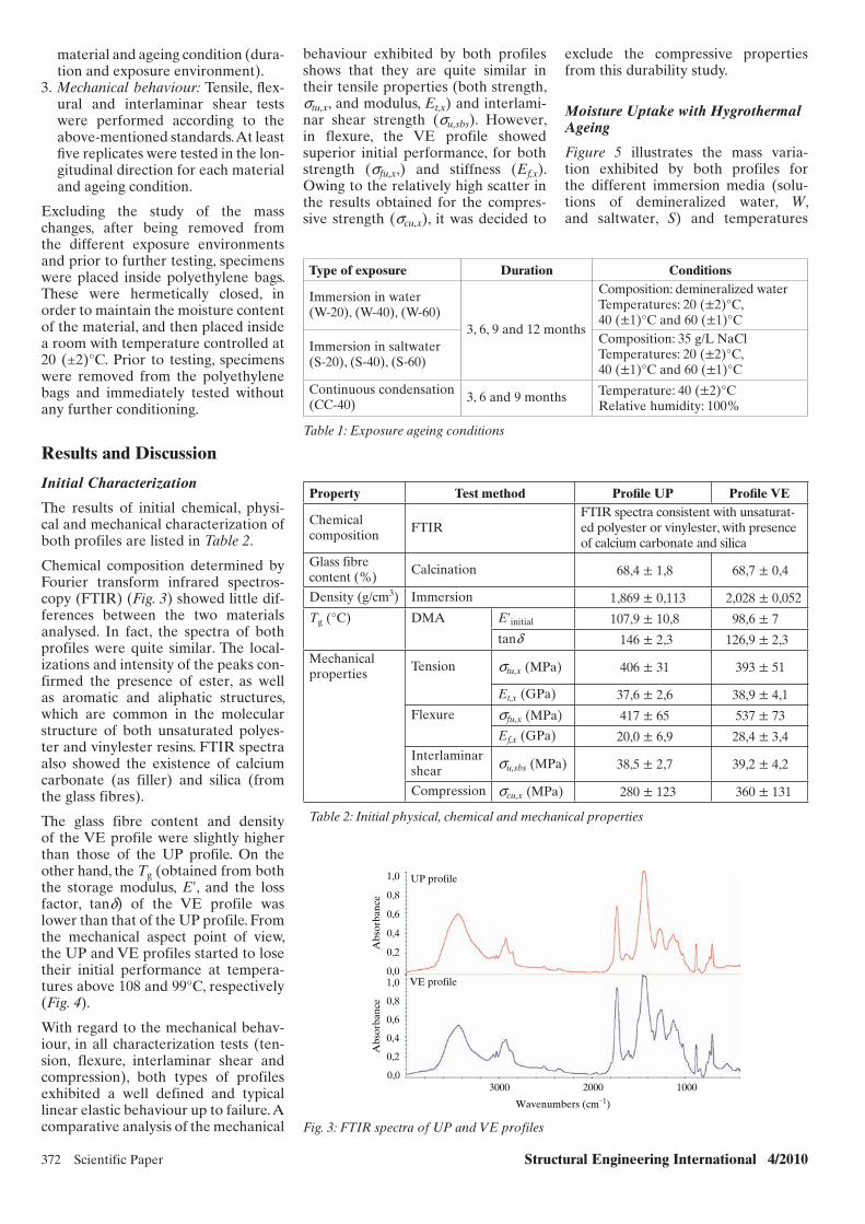
Chemical composition determined by Fourier transform infrared spectros-copy (FTIR) (Fig. 3) showed little dif-ferences between the two materials analysed. In fact, the spectra of both profiles were quite similar. The local-izations and intensity of the peaks con-firmed the presence of ester, as well as aromatic and aliphatic structures, which are common in the molecular structure of both unsaturated polyes-ter and vinylester resins. FTIR spectra also showed the existence of calcium carbonate (as filler) and silica (from the glass fibres).
The glass fibre content and density of the VE profile were slightly higher than those of the UP profile. On the other hand, the Tg (obtained from both the storage modulus, E′, and the loss factor, tand) of the VE profile was lower than that of the UP profile. From the mechanical aspect point of view, the UP and VE profiles started to lose their initial performance at tempera-tures above 108 and 99°C, respectively (Fig. 4).
With regard to the mechanical behav-iour, in all characterization tests (ten-sion, flexure, interlaminar shear and compression), both types of profiles exhibited a well defined and typical linear elastic behaviour up to failure. A comparative analysis of the mechanical
0,0
Abs
orba
nce
Abs
orba
nce
0,2
0,4
0,6
0,8
1,00,0
0,2
0,4
0,6
0,8
1,0
3000 2000 1000
UP profile
VE profile
Wavenumbers (cm–1)
Fig. 3: FTIR spectra of UP and VE profiles
Type of exposure Duration Conditions
Immersion in water(W-20), (W-40), (W-60)
3, 6, 9 and 12 months
Composition: demineralized waterTemperatures: 20 (±2)°C, 40 (±1)°C and 60 (±1)°C
Immersion in saltwater(S-20), (S-40), (S-60)
Composition: 35 g/L NaClTemperatures: 20 (±2)°C, 40 (±1)°C and 60 (±1)°C
Continuous condensation(CC-40)
3, 6 and 9 months Temperature: 40 (±2)°CRelative humidity: 100%
Table 1: Exposure ageing conditions
Property Test method Profi le UP Profi le VE
Chemical composition
FTIRFTIR spectra consistent with unsaturat-ed polyester or vinylester, with presence of calcium carbonate and silica
Glass fibre content (%)
Calcination 68,4 ± 1,8 68,7 ± 0,4
Density (g/cm3) Immersion 1,869 ± 0,113 2,028 ± 0,052
Tg (°C) DMA E′initial 107,9 ± 10,8 98,6 ± 7
tand 146 ± 2,3 126,9 ± 2,3Mechanical properties
Tension stu,x (MPa) 406 ± 31 393 ± 51
Et,x (GPa) 37,6 ± 2,6 38,9 ± 4,1
Flexure sfu,x (MPa) 417 ± 65 537 ± 73
Ef,x (GPa) 20,0 ± 6,9 28,4 ± 3,4Interlaminar shear su,sbs (MPa) 38,5 ± 2,7 39,2 ± 4,2
Compression scu,x (MPa) 280 ± 123 360 ± 131
Table 2: Initial physical, chemical and mechanical properties
behaviour exhibited by both profiles shows that they are quite similar in their tensile properties (both strength, stu,x, and modulus, Et,x) and interlami-nar shear strength (su,sbs). However, in flexure, the VE profile showed superior initial performance, for both strength (sfu,x,) and stiffness (Ef,x). Owing to the relatively high scatter in the results obtained for the compres-sive strength (scu,x), it was decided to
exclude the compressive properties from this durability study.
Moisture Uptake with Hygrothermal Ageing
Figure 5 illustrates the mass varia-tion exhibited by both profiles for the different immersion media (solu-tions of demineralized water, W, and saltwater, S) and temperatures
x051.indd 372x051.indd 372 27/10/10 6:51 PM27/10/10 6:51 PM

Structural Engineering International 4/2010 Scientific Paper 373
(20, 40 and 60°C), as well as in continu-ous condensation (CC) at 40°C.
Figure 5 shows that the evolution of all mass variation curves follow roughly a Fickian response (i.e. a fast initial mass gain that slows as saturation approaches), with rates of mass uptake increasing with temperature, particu-larly in the beginning of the exposure. It can also be seen that, for similar ageing conditions (immersion media and tem-peratures), the comparison of the mass variation exhibited by both profiles depicts significant differences, with the mass uptake for the VE profile being considerably lower than that exhibited by the UP profile for all hygrothermal ageing conditions; these differences, already reported by Chin et al.17, stem mainly from the distinct water absorp-tion capacities of both resin systems, in particular, the higher hydrolytic stabil-ity of VE resins. Figure 5 also shows that, for similar temperatures, mass uptake in saltwater was always lower than that in demineralized water, for both UP and VE profiles. Finally, one can readily observe that the increas-ing immersion temperature does not have a direct correlation with the increased level of mass uptake and this result should be attributed to the potential mass loss by extraction of low molecular components, an effect that is expected to increase with the immersion temperature. In fact, weight changes in these ageing processes usu-ally result from a balance between the water uptake due to moisture ingress and the loss of material. When com-pared with the immersion in deminer-alized water at 40°C, under continuous condensation at 40°C both materials exhibited a higher initial weight gain, although for longer periods, weight gains for those environments became quite similar.
DMA after Hygrothermal Ageing
Figure 4 shows the results of DMA after 12 months of immersion and 9 months of continuous condensation—for each condition, only one curve corresponding to a representative specimen is plotted. The left axis rep-resents the variation of E′ curves with temperature, which exhibit a charac-teristic “step” in the glass transition region; the right axis shows the corre-sponding tand curves, which present a typical peak in that region.
The variation in the behaviour exhib-ited by the E′ curves at the transition region reflects mainly the changes
0,000
0,25
0,50
0,75
1,00
1,25
1,50
(a)
(b)
1000 2000 3000 4000 5000 6000 7000 8000 9000
Mas
s va
riat
ion
(%)
Mas
s va
riat
ion
(%)
UP profile
Exposure period (h)
Exposure period (h)
0,000
0,25
0,50
0,75
1,00
1,25
1,50
1000 2000 3000 4000 5000 6000 7000 8000 9000
VE profile
W-20 W-40 W-60 S-20 S-40 S-60 CC-40
W-20 W-40 W-60 S-20 S-40 S-60 CC-40
Fig. 5: Mass variation of UP (a) and VE (b) profiles for different hygrothermal ageing conditions
0
5
10
15
20
25
(a)
(b)
25
Un-aged
50 75
Temperature (°C)
Temperature (°C)
100 125 150 175 2000
0,04
0,08
0,12
0,16
0,2UP profile
E′(G
Pa)
E′(G
Pa)
Tan
d (
–)T
an d
(–)
W-20 W-40 W-60 S-20 S-40 S-60 CC-40
Un-aged W-20 W-40 W-60 S-20 S-40 S-60 CC-40
0
5
10
15
20
25VE profile
25 50 75 100 125 150 175 2000
0,04
0,08
0,12
0,16
0,2
Tg,onset
Fig. 4: DMA 3-point bending curves of UP (a) and VE (b) profiles before and after hygrothermal ageing
x051.indd 373x051.indd 373 27/10/10 6:52 PM27/10/10 6:52 PM

374 Scientific Paper Structural Engineering International 4/2010
in the polymer matrix performance, which progresses from a glassy state to an elastomeric state, characteristic of its viscoelastic nature. In fact, the reinforced material (in this case, the glass fibres) does not suffer a stiffness reduction in this temperature range. Therefore, the DMA technique indi-cates the contribution of the viscoelas-tic nature of the matrix for the overall behaviour of the composite, and in the present study, this information is useful to help understand the actual influence of the matrix nature on the durability of the composite. In addition, the qual-ity of the fibre–matrix interface can also influence DMA results.
Figure 6 plots, in summary, the varia-tion of the Tg of both profiles (mean value ± standard deviation, determined based on the onset of E′), as a function of the type and duration of exposure.
For the UP profile, immersion in both demineralized water and salt-water caused, in general, a decrease in the value of Tg. It is seen that the maximum reduction in Tg occurred for specimens immersed in demineralized water, whereas the minimum reduc-tion corresponds to immersion in salt-water. After 12 months of exposure, Tg seems to increase with the immer-sion temperature for both media; for saltwater immersion at 60°C, the Tg becomes even higher than that of the un-aged material, most likely due to a post-curing phenomenon, induced
by the increased temperature. For the UP profile, the tand curves for con-tinuous condensation, and immersion in demineralized water at 60°C show the appearance of a second “peak” at higher temperatures (Fig. 4). The occur-rence of this second peak, associated to the widening of its base, suggests that the ageing of the material involves a plasticization mechanism. The occur-rence of two “peaks” in the tanδ curve may be attributed to the different mobility of two kinds of segments in the polymeric matrix, caused by their different extents of plasticization.
For the VE profile, the variation of Tg was less dependent on the immersion temperature and, in general, its varia-tion was less significant than that veri-fied in the UP profile. The tand curves for the VE profile did not show any widening, suggesting that the molecu-lar structure did not suffer significant changes. The only exceptions were the immersions at 60°C in both media, in which an asymmetry could be observed in the configuration of the tand curves, near their maximum value. This result is consistent with the lower water uptake ability exhibited by this material, when compared with the UP profile.
Water uptake by unsaturated polyester and vinylester composites is known to cause plasticization in the short term and hydrolysis over the long term through attack of the ester linkages.18 As the ester group is located in the
middle of the molecular structure of polyester, and in the ends of the molec-ular structure of vinylester, in principle, the later resin is more resistant to the above-mentioned plasticization mech-anisms. Both these phenomena induce higher levels of molecular mobility, resulting in a consequent decrease in the Tg, although such decrease can often be offset through residual curing of the resins in aqueous media. These competing phenomena result in fluc-tuations in the Tg as a function of the exposure period; in the experiments reported herein, such behaviour was shown, in particular, by the UP profile.
Mechanical Performance after Hygrothermal Ageing
Tensile Properties
The results obtained from tensile tests on both materials, namely, the tensile strength and the tensile modulus as a function of time and hygrothermal conditions, are presented in Fig. 7.
Figure 7 shows that for all ageing con-ditions and for both materials there was an overall decrease in the average tensile strength with the duration of exposure (the only exception was the VE profile after 12 months of expo-sure in demineralized water at 20°C). As expected, the level of degradation of the tensile strength increased con-sistently with the temperature of the immersion medium, with maximum reductions occurring at 60°C—after 12 months of exposure, the lowest levels of retention were 64 and 75% for the UP and VE profiles, both immersed in demineralized water. The general higher aggressiveness of demineral-ized water compared to saltwater was consistent with previous investigations (e.g. those reported by Van de Velde and Kiekens19) and could be attributed to osmotic effects. For all hygrothermal ageing conditions and periods of expo-sure, the tensile strength retention of the VE profile was consistently higher than that of the UP profile. Chu et al.20 reported tensile strength reductions in pultruded E-glass vinylester lami-nates that follow the overall trend of the present tests—the strength reten-tion presented by those authors was considerably smaller, but so was the thickness of the tested material and, consequently, the maximum moisture uptake.
The variation exhibited by the aver-age tensile modulus with the expo-sure period (Fig. 7), which was much more irregular and associated with
0
(a)
(b)
UP profile
VE profile
W-20 W-40 W-60 S-20 S-40 S-60 CC-40
W-20 W-40 W-60 S-20 S-40 S-60 CC-40
20
40
60
80
100
120
140
0
20
40
60
80
100
120
140
Tg
(E')
[°C
]T
g (E
') [°
C]
Initial 3 months 6 months 9 months 12 months
Initial 3 months 6 months 9 months 12 months
Fig. 6: Glass transition temperature of UP (a, c) and VE (b, d) profiles after hygrothermal ageing
x051.indd 374x051.indd 374 27/10/10 6:52 PM27/10/10 6:52 PM

Structural Engineering International 4/2010 Scientific Paper 375
higher coefficients of variation (when compared to the tensile strength), makes it more difficult to establish systematic analyses and comparisons between the two materials. However, for all exposure conditions and dura-tions, one can conclude that the stiff-ness retention was considerably higher than the corresponding strength reten-tion—the minimum levels of retention after 12 months were 76% for the UP profile (saltwater at 20°C) and 85% for the VE profile (saltwater at 60°C). In addition, and similar to the tensile strength, the stiffness retention of the VE profile was always higher than that exhibited by the UP profile. Finally, when compared to strength, stiffness retention appeared to be much more insensitive to the temperature and composition of the immersion media.
For both profiles the strength and stiff-ness retention of specimens immersed in demineralized water at 40°C was comparable to that of specimens under continuous condensation (particularly for the VE profile) and this result agrees well with the water uptake measurements.
Flexural Properties
The results obtained from flexural tests, namely the flexural strength and the flexural modulus, on both materi-als are presented as a function of time and hygrothermal conditions in Fig. 8.
In general, the level of degradation of the flexural strength of both profiles increased with the temperature of the immersion medium, being maximum at 60°C—this result was in agreement with the behaviour already reported for the tensile strength and with results obtained by other authors with GFRP pultruded profiles.19,21 As for the ten-sile strength, for similar temperatures, strength reduction in demineralized water was usually lower than that in saltwater (it should be mentioned that this latter result differs from those reported by Liao et al.22) Unlike the behaviour exhibited in the tensile tests (essentially dominated by the fibres), in flexure (also significantly influenced by the matrix and the fibre–matrix interface) the VE profile did not pres-ent a better mechanical performance than the UP profile for all ageing conditions; in fact, for most exposure conditions and durations, the strength retention of the VE profile was consid-erably smaller than that of the UP pro-file—after 12 months of exposure, the lowest levels of retention were 66% for the UP profile and 58% for the VE profile, both immersed in demin-eralized water. This result may be due, at least to some extent, to some post-curing effect on the UP profile, which was identified in the DMA tests, and, in addition, to the considerable scatter of the results obtained in the initial char-acterization flexural tests. In this regard, it is worth mentioning that Kootsookos
0W-20 W-40 W-60 S-20
50100150200250300350400450500
S-40 S-60 CC-40
W-20 W-40 W-60 S-20 S-40 S-60 CC-40 W-20 W-40 W-60 S-20 S-40 S-60 CC-40
0W-20 W-40 W-60 S-20
50100150200250300350400450500
S-40 S-60 CC-40
Ten
sile
str
engt
h (M
Pa)
Ten
sile
mod
ulus
(G
Pa)
Ten
sile
mod
ulus
(G
Pa)
Ten
sile
str
engt
h (M
Pa)
05
10152025303540455055
05
10152025303540455055
UP profile
(a) (b)
(c) (d)
VE profile
VE profileUP profile
Initial 3 months 6 months 9 months 12 months
Initial 3 months 6 months 9 months 12 months Initial 3 months 6 months 9 months 12 months
Initial 3 months 6 months 9 months 12 months
Fig. 7- Tensile strength and modulus of UP (a, c) and VE (b, d) profiles after hygrothermal ageing
and Mouritz23 also reported higher flexural strength retention in moulded glass–polyester laminates, compared with glass–vinylester laminates having similar fibre architectures.
Flexural modulus after 12 months of exposure decreased in all ageing condi-tions, for both profiles (Fig. 8). Similar to strength, in general, stiffness reten-tion in demineralized water was lower than that in saltwater and, in addi-tion, the UP profile presented better performance than the VE profile—the lowest levels of retention were 69% for the UP profile and 58% for the VE profile, both immersed in demineral-ized water. Similar to the tensile mod-ulus, the flexural stiffness retention appeared to be more insensitive to the temperature of the immersion media, when compared to strength.
As for tensile performance, the varia-tion of flexural properties in specimens subjected to continuous condensa-tion was roughly similar to that of specimens immersed in demineralized water at 40°C.
Interlaminar Shear Strength
Figure 9 illustrates the variation of the interlaminar shear strength (a matrix dominated property) of both profiles as a function of the hygrothermal con-ditions and the period of exposure.
Figure 9 shows that very significant reductions occurred in the interlaminar
x051.indd 375x051.indd 375 27/10/10 6:52 PM27/10/10 6:52 PM
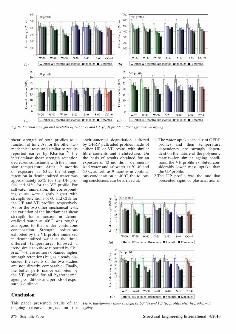
376 Scientific Paper Structural Engineering International 4/2010
0
100
200
300
400
500
600
(a) (b)
(c) (d)
W-20 W-40 W-60 S-20 S-40 S-60 CC-40
W-20 W-40 W-60 S-20 S-40 S-60 CC-40
0
100
200
300
400
500
600
700
W-20 W-40 W-60 S-20 S-40 S-60 CC-40
W-20 W-40 W-60 S-20 S-40 S-60 CC-40
Fle
xura
l str
engt
h (M
Pa)
Fle
xura
l mod
ulus
(G
Pa)
Fle
xura
l mod
ulus
(G
Pa)
Fle
xura
l str
engt
h (M
Pa)
0
5
10
15
20
25
30
35
0
5
10
15
20
25
30
35
UP profile VE profile
VE profileUP profile
Initial 3 months 6 months 9 months 12 months Initial 3 months 6 months 9 months 12 months
Initial 3 months 6 months 9 months 12 months Initial 3 months 6 months 9 months 12 months
Fig. 8– Flexural strength and modulus of UP (a, c) and VE (b, d) profiles after hygrothermal ageing
Initial 3 months 6 months 9 months 12 months
Initial 3 months 6 months 9 months 12 months
50454035302520151050In
terl
. she
ar s
tren
gth
(MP
a)In
terl
. she
ar s
tren
gth
(MP
a)
CC-40S-60S-40S-20W-60W-40W-20
CC-40S-60S-40S-20W-60W-40W-20
50
(a)
(b)
454035302520151050
VE profile
UP profile
Fig. 9: Interlaminar shear strength of UP (a) and VE (b) profiles after hygrothermal ageing
shear strength of both profiles as a function of time. As for the other two mechanical tests, and similar to results reported earlier by Kharbari,24 the interlaminar shear strength retention decreased consistently with the immer-sion temperature. After 12 months of exposure at 60°C, the strength retention in demineralized water was approximately 55% for the UP pro-file and 61% for the VE profile. For saltwater immersion, the correspond-ing values were slightly higher, with strength retentions of 60 and 62% for the UP and VE profiles, respectively. As for the two other mechanical tests, the variation of the interlaminar shear strength for immersion in demin-eralized water at 40°C was roughly analogous to that under continuous condensation. Strength reductions exhibited by the VE profile immersed in demineralized water at the three different temperatures followed a trend similar to those reported by Chu et al.20—these authors obtained higher strength retentions but, as already dis-cussed, the results of the two studies are not directly comparable. Finally, the better performance exhibited by the VE profile for all hygrothermal ageing conditions and periods of expo-sure is outlined.
Conclusion
This paper presented results of an ongoing research project on the
environmental degradation suffered by GFRP pultruded profiles made of either UP or VE resins, with similar fibre contents and architectures. On the basis of results obtained for an exposure of 12 months in demineral-ized water and saltwater at 20, 40 and 60°C, as well as 9 months in continu-ous condensation at 40°C, the follow-ing conclusions can be arrived at:
1. The water uptake capacity of GFRP profi les and their temperature dependency are strongly depen-dent on the nature of the polymeric matrix—for similar ageing condi-tions, the VE profi le exhibited con-siderably lower mass uptake than the UP profi le.
2.The UP profi le was the one that presented signs of plasticization in
x051.indd 376x051.indd 376 27/10/10 6:53 PM27/10/10 6:53 PM
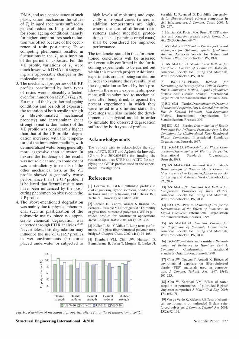
Structural Engineering International 4/2010 Scientific Paper 377
DMA, and as a consequence of such plasticization mechanism the values of Tg in aged specimens suffered a general reduction. In spite of this, for some ageing conditions, namely for higher temperatures, such reduc-tion was offset because of the occur-rence of resin post-curing. These competing phenomena resulted in fl uctuations in the Tg as a function of the period of exposure. For the VE profi le, variations of Tg were much lower, with DMA not suggest-ing any appreciable changes in the molecular structure.
3. The mechanical properties of GFRP profi les constituted by both types of resins were noticeably affected, even for immersion at 20°C (Fig. 10). For most of the hygrothermal ageing conditions and periods of exposure, the retention of both tensile strength (a fi bre-dominated mechanical property) and interlaminar shear strength (matrix dominated) of the VE profi le was considerably higher than that of the UP profi le—degra-dation increased with the tempera-ture of the immersion medium, with demineralized water being generally more aggressive than saltwater. In fl exure, the tendency of the results was not so clear and, to some extent was contradictory to results of the other mechanical tests, as the VE profi le showed a generally worse performance than the UP profi le. It is believed that fl exural results may have been infl uenced by the post-curing phenomen on observed in the UP profi le.
4. The above-mentioned degradation was mainly due to physical phenom-ena, such as plasticization of the polymeric matrix, since no appre-ciable chemical degradation was detected through FTIR analyses.25,26 Nevertheless, this degradation may infl uence the use of GFRP profi les in wet environments (structures placed underwater or subjected to
high levels of moisture) and espe-cially in tropical zones (where, in addition, temperatures are high), where the use of different resin systems and/or superfi cial protec-tions (such as paintings or gel coats) shall be considered for improved performance.
The tendencies stated in the aforemen-tioned conclusions will be assessed and eventually confirmed in the forth-coming experiments to be carried out within this research project. Additional experiments are also being carried out in order to evaluate the reversibility of the degradation suffered by both pro-files—in these new experiments, speci-mens will be submitted to mechanical tests after being dried, as against the present experiments, in which they were tested in a saturated state. The next steps will also include the devel-opment of analytical models in order to simulate the observed degradation suffered by both types of profiles.
Acknowledgements
The authors wish to acknowledge the sup-port of FCT, ICIST and Agência da Inovação (Grant No. 2009/003456) for funding the research and also STEP and ALTO for sup-plying the GFRP profiles used in the experi-mental investigations.
References
[1] Correia JR. GFRP pultruded profiles in civil engineering: hybrid solutions, bonded con-nections and fire behaviour, PhD Thesis, IST, Technical University of Lisbon, 2008.
[2] Correia JR, Cabral-Fonseca S, Branco FA, Ferreira J, Eusébio MI, Rodrigues MP. Durability of glass fibre reinforced polyester (GFRP) pul-truded profiles for construction applications. Mech. Compos. Mater. 2006; 42(4): 325–338.
[3] Keller T, Bai Y, Vallée T. Long-term perfor-mance of a glass-fiber-reinforced polymer truss bridge. J. Compos. Const. 2007; 11(1): 99–108.
[4] Kharbari VM, Chin JW, Hunston D, Benmokrane B, Juska T, Morgan R, Lesko JJ,
0
20
40
60
80
100
120
Pro
pert
y re
tent
ion
(%)
Tensilestrength
Tensilemodulus
Flexuralstrength
Flexuralmodulus
Int. shearstrength
UP-W-20 VE-W20 UP-S-20 VE-S-20
Fig. 10: Retention of mechanical properties after 12 months of immersion at 20°C
Sorathia U, Reynaud D. Durability gap analy-sis for fiber-reinforced polymer composites in civil infrastructure. J. Compos. Const. 2003; 7: 238–247.
[5] Harries KA, Porter MA, Busel JP. FRP mate-rials and concrete research needs. Concr. Int., ACI 2003; October: 69–74.
[6] ASTM~E~1252. Standard Practice for General Techniques for Obtaining Spectra Qualitative Analysis. American Society for Testing and Materials, West Conshohocken, PA, 1998.
[7] ASTM~D~3171. Standard Test Methods for Constituent Content of Composite Materials. American Society for Testing and Materials, West Conshohocken, PA, 2009.
[8] ISO~1183—Plastics. Methods for Determining the Density of Non-Cellular Plastics. Part 1: Immersion Method, Liquid Pyknometer Method And Titration Method. International Organization for Standardization, Brussels, 2004.
[9] ISO~6721—Plastics. Determination of Dynamic Mechanical Properties. Part 1: General Principles; Part 5: Flexural Vibration- Non-Resonance Method. International Organization for Standardization, Brussels, 2001.
[10] ISO~527—Plastics. Determination of Tensile Properties. Part 1: General Principles; Part~5: Test Conditions for Unidirectional Fiber-Reinforced Plastic Composites, International Standards Organization, Brussels, 1997.
[11] ISO~14125. Fiber-Reinforced Plastic Com-posites—Determination of Flexural Properties, International Standards Organization, Brussels, 1998.
[12] ASTM~D~2344. Standard Test for Short-Beam Strength of Polymer Matrix Composite Materials and Their Laminates, American Society for Testing and Materials, West Conshohocken, PA, 2006.
[13] ASTM~D~695. Standard Test Method for Compressive Properties of Rigid Plastics. American Society for Testing and Materials, West Conshohocken, PA, 2008.
[14] ISO~175—Plastics. Methods of Test for the Determination of the Effects of Immersion in Liquid Chemicals. International Organisation for Standardization, Brussels, 1999.
[15] ASTM~D~1141. Standard Practice for the Preparation of Substitute Ocean Water. American Society for Testing and Materials, West Conshohocken, PA, 2008.
[16] ISO~6270—Paints and varnishes. Determi-nation of Resistance to Humidity. Part 1: Continuous Condensation, International Standards Organization, Brussels, 1998.
[17] Chin JW, Nguyen T, Aouadi K. Effects of environmental exposure on fiber- reinforced plastic (FRP) materials used in construc-tion. J. Compos. Technol. Res. 1997; 19(4): 205–213.
[18] Chu W, Karbhari VM. Effect of water sorption on performance of pultruded E-glass/ vinylester composites. J. Mater. Civil Eng. 2005; 17(1): 63–71.
[19] Van de Velde K, Kiekens P. Effects of chemi-cal environments on pultruded E-glass rein-forced polyesters. J. Compos. Technol. Res. 2001; 23(2): 92–101.
x051.indd 377x051.indd 377 27/10/10 6:53 PM27/10/10 6:53 PM

378 Scientific Paper Structural Engineering International 4/2010
[20] Chu W, Wu L, Kharbari VM. Durability evaluation of moderate temperature cured E-glass/vinlyester systems. Compos. Struct. 2004; 66(1–4): 367–376.
[21] Nishizaki I, Meiarashi S. Long-term deterio-ration of GFRP in water and moist environment. J. Compos. Const. 2002; 6(1): 21–27.
[22] Liao K, Schultheisz CR, Hunston DL. Effects of environmental aging on the properties
of pultruded GFRP. Compos. B: Eng. 1999; 30(5): 485–493.
[23] Kootsookos A, Mouritz AP. Seawater dura-bility of glass- and carbon-polymer composites. Compos. Sci. Technol. 2004; 64(10–11): 1503–1511.
[24] Kharbari VM. E-Glass/vinylester compos-ites in aqueous environments: effects on short-beam shear strength. J. Compos. Const. 2004; 8(2): 148–156.
[25] Costa R. Durability of Glass Fibre Reinforced Polyester Pultruded Profiles. MSc Thesis, IST, Technical University of Lisbon, 2009 (in Portuguese).
[26] Carreiro A. Durability of Glass Fibre Reinforced Vinylester Pultruded Profiles. MSc Thesis, IST, Technical University of Lisbon, 2010 (in Portuguese).
Global Thinking in Structural Engineering:Recent Achievements
IABSE Conference Cairo EgyptMay 7-9, 2012
The Egyptian Group of IABSEThe Egyptian Society of Engineers
Organised by
More information: [email protected]
International Association for Bridgeand Structural Engineering
x051.indd 378x051.indd 378 27/10/10 6:53 PM27/10/10 6:53 PM

Peer-reviewed by international ex-perts and accepted for publication by SEI Editorial Board
Paper received: March 14, 2010Paper accepted: May 21, 2010
Structural Engineering International 4/2010 Scientific Paper 379
Evaluation of a Life Prediction Model and Environmental Effects of Fatigue for Glass Fiber Composite MaterialsDavid Brian Dittenber, Ph.D. Student; GangaRao V.S. Hota, Prof., Director of Constructed Facilities Center; Civil Eng. Dept.,
West Virginia University, USA. Contact: [email protected]
Abstract
Fiber-reinforced polymer (FRP) composites are being utilized in an increasing number of applications in structural industries. Establishing values for long-term fatigue response is essential for widespread use of FRP composites. The variety of available fibers, matrix materials, and manufacturing processes makes the fatigue response difficult to predict without extensive empirical testing. A proposed fatigue life prediction model uses the internal strain energy release rate as the metric for predicting fatigue life from a minimum of data points. The objective of this research was to apply the above model to fatigue data for vari-ous composite coupons and components in order to evaluate its applicability in predicting fatigue life. The model was found to be able to regularly fit and pre-dict fatigue data within 5% log error at both coupon and component levels. The effects of environmental conditions, including 12 MPa pressurized absorption and fatiguing in salt water and elevated temperatures, were also explored for a glass/vinyl ester FRP. The results of this research can be used to aid in the design of numerous structural FRP applications, such as windmill blades, bridge decks, or deep sea piping.
Keywords: FRP composites; fatigue life prediction; temperature effects; saltwater environment; component fatigue; strain energy.
the performance of a material, but fatigue testing is time consuming and costly. Therefore, observed behav-ioral trends need to be combined with established physical relationships in order to produce mathematical models to predict fatigue life with reasonable accuracy. Many researchers have devel-oped fatigue life prediction models for composites in the past few decades, but none have been widely adapted in industry.
Fatigue in Composites
When the weakest location in a com-posite fails, the surrounding fiber/matrix interface experiences increased local stresses, which can lead to fatigue damage. The weakest location is typi-cally caused by material defects, such as misaligned fibers, voids, or resin-rich regions. As fatigue damage progresses, cracks in either the resin or the resin/matrix interface develop between the fibers, causing many to become over-loaded and fail. In order to predict the fatigue behavior of a material, the remaining strength or the remaining number of cycles, the material prop-erties and the environmental/loading conditions must be related to the vari-ous damage modes that the material is likely to experience.
When developing a fatigue life predic-tion model, it is important to evaluate how the model is able to handle a vari-ety of materials and test conditions. Several researchers have compiled a large composite material fatigue data-base consisting of data from fatigue testing on wind turbine blade materi-als.2,3 Over 190 polymeric composite materials with over 12 000 individual coupon tests were conducted. Their research was focused on materials with lay-up combinations of 0°, ±45°, and 0°/±45° fabrics, manufactured by either hand lay-up or resin transfer molding (RTM).
Fatigue Model Development
The proposed GFRP fatigue life model4 uses the internal strain energy of the material as the damage metric; this energy is expended due to dam-age in the forms of matrix cracking, fiber/matrix interface failure, delami-nations, or fiber breakage before rup-ture. Strain energy was chosen as the damage metric because of its ability to represent multiple damage modes through one measurement and its high sensitivity to damage accumulation due to the squaring of the stress/strain term. While other researchers5 have previously used the strain energy to predict fatigue life, this more recent model differs in the following ways:
1. It is laminate-derived instead of lamina-derived, meaning no ply mechanics calculations need to be made.
2. It focuses on utilizing a minimum number of experimental tests to determine material coeffi cients.
3. It relates the strain energy back to the stress versus number of cycles curve in order to provide physical meaning.
4. It is intended for use in industry, therefore attempts to simplify the process while still providing a rea-sonable fatigue life prediction.
The expenditure of strain energy occurs in three stages (Fig. 1): Stage I is a steep curve of energy loss as the
Introduction
Fiber-reinforced polymer (FRP) composites offer an opportunity to revolutionize and rehabilitate infra-structure because of their advantages over traditional structural materials: higher strength, higher fatigue and impact resistance, higher corrosive and environmental resistance, longer ser-vice life, lower installation and main-tenance costs, and more consistent performance.1
FRPs are composites that have rein-forcement in the form of fibers and matrix in the form of a polymeric material, that is, epoxy, vinyl ester, or polyester. The most common fiber reinforcements are glass and carbon fibers, but the higher cost of carbon generally prohibits their use for infra-structure. Glass fiber-reinforced poly-mers (GFRPs) are lightweight and have a good combination of mechani-cal performance per unit cost.
Performing extensive experimental work is one way to fully characterize
x073.indd 379x073.indd 379 10/25/10 12:28 PM10/25/10 12:28 PM

380 Scientific Paper Structural Engineering International 4/2010
NUU N
U
abf
o o
ultd d
= ( ) =( )( )2 2 σ σmax
(10)
Model Evaluation
Fatigue test results were selected from the composite material fatigue data-base2 using the following controlling criteria:
1. Tension–tension testing2. Stress ratio (smin/smax ), R = 0,13. Minimum three load levels (between
25 and 75% of max stress)4. Minimum fi ve tests run to failure
with at least 100 cycles each5. E-glass fi bers6. Fatigue rate ≤ 20 Hz7. Generally ordered results (if s1 > s2,
then N1 < N2).
After applying these criteria, test results for 109 different composites (1254 individual tests) were analyzed.
Each material listing in the database included its static modulus of elas-ticity, static ultimate strength, and coupon dimensions, with stress load levels and number of cycles to fail-ure for each coupon. Polyester was the most common matrix material, but results for vinyl ester, epoxy, and thermoplastic matrices were included. Most of the laminates selected were manufactured by RTM or lay-up tech-niques but included a variety of fiber architectures.
For each composite, the fatigue coeffi-cients (a and b) were obtained through a power regression on the criteria-selected data after plotting the results of Eqs. (8) and (9) (Fig. 2). Using the fatigue coefficients, the curve gener-ated by Eq. (10) was plotted against the data on a log scale (see Fig. 3).
In order to assess the accuracy of the model in fitting data, curves of ±5% log(Nf) and ±10% log(Nf) were gener-ated, with any data lying within these envelopes considered to be reasonably well-modeled (Fig. 3). The number of data points within each error envelope was then tallied for each sample.
Results
Composite Material Fatigue Database
The results of the fatigue database2 analysis of the model are shown in Table 1. Since data scatter is as likely as a poor-fitting model to result in data
Exp
ende
d en
ergy
(U
)
Stage I Stage II (Linear) Stage III
Cycles to failure (N)
Failure
Fig. 1: Three stages of energy expenditure in fatigue
of the sample, L is the gage length, and Estatic is the static modulus of elasticity.4
UAL
E0
2
2= mean
static
(4)
After analyzing experimental strain energy release results for several GFRP fatigue tests, it was observed that the strain energy expended at ~90% of the fatigue life (the end of Stage II) was consistently close to 1,5 times the ini-tial strain energy, U0. The data point at the end of Stage II can therefore be defined as (Nf, Uf), as shown in Eqs. (5) and (6).4
U Uf 1 5 0, (5)
N Nf ult0 9, (6)
The energy release rate per cycle is relatively constant within Stage II and is dependent on the material type and loading conditions. Plotting the normal-ized strain against the energy release rate, the data can be curve-fitted with a power law as shown below, where a and b are the fatigue coefficients.
dd ult
UN
ab
=⎛⎝⎜
⎞⎠⎟
εε
max (7)
Because of the linearity of the Stage II energy release, dU/dN can be approxi-mated as ΔU/ΔN [Eq. (8)]. If we assume that the strain ratio can be approxi-mated as equivalent to the stress ratio due to a linear relationship between the stress and strain of the material [Eq. (9)], Nf can be calculated as shown in Eq. (10).
dd f f
UN
UN
U UN
UN
= = =1 5
20 0 0,
(8)
max max
ult ult
(9)
material is initially loaded, and gener-ally lasts for about 15% of the fatigue life; Stage II is nearly linear, with the slope a characteristic of the material and testing conditions, and generally lasts for about 75% of the fatigue life; Stage III is again a steep curve leading to material rupture over the last 10% of the fatigue life.4,6
Equation (1) describes the rate of the release of strain energy, Uj, with respect to the number of cycles, Nj, as a function of the mean strain, em, the strain range, er, the amount of expended strain energy corresponding to the current cycle count, and the par-ticular composite material type, Ct.
4 If the material type is kept constant, then this relationship supposes that the rate of release of strain energy with respect to the number of cycles is a function of the loading conditions:
d
d m r t
U
Nf U Cj
jj= ( ), , , (1)
The strain energy at any cycle of a fatigue test can be determined from the deflection (or strain) and loading data; for a tension–tension fatigue test, this is shown in Eq. (2), where Pj is the load and dj is the deflection at any cycle j:
UP
jj j=2
(2)
To account for more complex material properties, it would be acceptable to use different versions of the strain energy equation. The strain energy density, W, could be calculated as shown in Eq. (3) for elastic plane stress problems.5
W x x y y xy xy= + +( ) / 2 (3)
The strain energy model calculates the initial strain energy U0 using the mean loading stress (smean) just prior to initiating fatigue, as shown in Eq. (4), where A is the cross sectional area
x073.indd 380x073.indd 380 10/25/10 12:28 PM10/25/10 12:28 PM

Structural Engineering International 4/2010 Scientific Paper 381
at a time produced no noticeable trends in the values of either the a or b coefficients: matrix type, com-mon fiber architecture, manufacturing process, material thickness, material cross-sectional area, modulus of elas-ticity, testing rate, and ultimate tensile strength. The differences in matrices may have had a slight impact on the b-coefficient (with epoxies averaging 11,8, polyesters 11,9, and vinyl esters 12,1), but was not large enough to be significant and did not account for the high degree of variation within each of those groups.
The linear approximation of Eq. (11) was obtained by running regressions on plots of the fiber volume fraction versus the b-coefficient for several smaller groupings of RTM polyes-ter-matrix data (e.g. unidirectional samples, 0°/45° samples, etc.). Plotting the b-coefficient against the fiber vol-ume fraction still does not account for the high amount of scatter (Fig. 4), but does allow for a reasonable aver-age to be obtained. An attempt was made to normalize the fiber content with respect to the 0° direction before plotting against the b-coefficient, but it did not provide any better an approxi-mation. Equation (11) provides an approximation of the b-coefficient for a majority of samples only if they have polyester matrices and were manufac-tured by RTM; the error can be much higher for those samples with other matrices or manufacturing methods.
The percentages of the 126 data points that fell within the ±5 and ±10% error envelopes using between one and nine data points to obtain the fatigue coef-ficients are shown in Fig. 5.
Glass/Vinyl Ester Composite
The same logarithmic error envelope analysis was carried out using fatigue test results from a glass/vinyl ester com-posite material. Six tension– tension fatigue tests were run at six different stress levels between 35 and 70% of the ultimate static strength.
After performing a similar curve fit analysis as was conducted on the data-base materials, it was determined that the material had an R2 value of 0,995 for the power regression and that all of the six data points lay within the ±5% error envelope (Fig. 3). After assessing the curve prediction analy-sis, it was found that at least five of the data points fell within the ±5% error envelope using between two and six samples to obtain the fatigue
Total Within 5% log error Within 10% log error
Number Number Percentage (%) Number Percentage (%)
Full data set 1260 1034 82,1 1222 97
R2 > 0,9 1201 1003 83,5 1171 97,5
R2 > 0,95 1099 935 85,1 1078 98,1
R2 > 0,98 623 565 90,7 621 99,7
Table 1: Log error anal ysis results
Fig. 3: Typical log error analysis (on glass/vinyl ester composite)
0,85
0,75
0,65
0,55
0,45
0,35
0,250 2 4 6 8 10
Nor
mal
ized
max
str
ess
(sm
ax/s
ult)
Cycles to failure (Log N)
Actual
Model fit
Upper limit (+10%)
Lower limit (−10%)
Upper limit (+5%)
Lower limit (−5%)
10
9
8
7
6
5
4
3
2
1
0
Ene
rgy
rele
ase
rate
ΔU/Δ
N in
N-m
m/c
ycle ΔU/ΔN
Power (ΔU/ΔN)
0 0,2 0,4 0,6 0,8
Normalized applied stress (smax/sult)
y = 2610,44 × 17,67R2 = 0,989
Fig. 2: Typical mate rial energy release rate
points located outside of these error envelopes, results were also considered for different correlation coefficient (R2) values obtained from the initial power regression. A higher R2 value would indicate less scatter; using R2 > 0,98 (Table 1) the model is able to fit over 90% of the fatigue data to within the ±5% error envelope.
Once it had been shown that the model provided good accuracy at fit-ting the data, another analysis was run to assess its ability to predict coupon fatigue life. Only composites with poly-ester matrices and a total of nine data points were considered, resulting in 14 laminates and a total of 126 fatigue
tests. The same curve equation and error envelopes were generated for each composite using several different fatigue coefficients. The power regres-sion was performed using anywhere from two to nine logically selected data points and the number of data points within the error envelopes was tallied. A curve was also generated for each composite using only a single data point (~50% ultimate strength) and the loose correlation of Eq. (11).
b = ( )20 1 fiber volume fraction (11)
Grouping and analyzing the data by one or more of the following characteristics
x073.indd 381x073.indd 381 10/25/10 12:28 PM10/25/10 12:28 PM

382 Scientific Paper Structural Engineering International 4/2010
both beams. If only two data points were used to obtain the fatigue coef-ficients, five of the six data points were within the ±2,5% error enve-lope and all six were within the ±5% error envelope. An appropriate b- approximation has not yet been determined for component fatigue, so a single-sample fatigue life predic-tion could not be obtained.
Environmental Effects on Fatigue in Composites
Both increased temperature and the presence of moisture have similar effects on polymeric composites—both induce stress by swelling and both relax stress by softening.8 Several research-ers9 have shown that the fatigue damage accumulation sequence was essentially the same at each temperature level they tested (ranging between −20 and 150°C) but the rate of accumulation increased with temperature.
Fatigue tests on the tested glass/vinyl ester composite coupons were con-ducted under varying environmental conditions in both bending and ten-sion–tension fatigue with an R-ratio (smin/smax) of 0,2. The environmental conditions included the absence or presence of salt water during testing, elevated temperatures, and acceler-ated immersion preconditioning (at 12 MPa), and testing was performed at several stress levels (from 35 to 70% of ultimate stress). While it has been shown10 that the absence or presence of salt often has little effect on the performance of composites, salt water was used for the testing in order to most closely simulate ocean conditions.
In bending fatigue, the most common failure mode was delamination of the outer layers on the tension side of the sample, believed to be initiated by microcracking at the midpoint. The presence of salt water reduced the fatigue life of the material to 84% of the value of a dry test at room tem-perature and a stress level of 63% of ultimate load, and to 54% of the value of a dry test at room temperature and a stress level of 50%. The effect of temperature on the life of the material was found to be approximately linear (with a higher temperature leading to a reduction in fatigue life), at least on those samples that were also tested in a salt water environment (see Fig. 7). The tests confirmed that the fatigue life of the material is decreased by the
analysis could be run for full-scale components. Segments of the beams, each of dimensions 120 mm × 120 mm × 6,5 mm were fatigue tested over a span of 1,83 m.
UILEc0
mean static=2
26 (12)
The R2 values on the power regres-sion for the box and I-beams were 0,967 and 0,985, respectively. All 12 of the data points lay within the ±5% error envelopes; in fact, they were also all within curves of ±2,5% log(Nf) (Fig. 6). The prediction anal-ysis revealed that using anywhere between three and six data points to obtain the fatigue coefficients resulted in all six data points being within the ±2,5% error envelope for
coefficients (Table 2). An appropri-ate b- approximation has not yet been determined for this resin type, so a single-sample fatigue life prediction could not be obtained.
Component Data
Generally, few fatigue tests are run to failure on composite components owing to the difficulty and expense of full-scale testing. One researcher7 ran six bending fatigue tests each on two glass/vinyl ester composite beams (one an I-beam, the other a box beam). Using his data and an adapta-tion of U0 for strain and bending [see Eq. (12), where I is the moment of inertia of the sample, L is again the gage length, and c is the distance from the neutral axis], a fit and prediction
Number of samples used
a-Coeffi cient b-Coeffi cient R2 value Within 5% Within 10%
2 5,969 14,245 1 6 63 5,998 14,246 1 6 64 4,990 14,122 0,998 5 65 5,006 14,085 0,997 5 66 6,616 14,39 0,995 6 6
Table 2: Model coeffi cients and prediction analysis for glass/vinyl ester composite
Fig. 4: L inear regression on b-coefficient versus fiber volume fraction (0/±45 fibers)
20
18
16
14
12
10
8
6
4
2
0
b-C
oeff
icie
nt
0,600,20 0,25 0,30 0,35 0,40 0,45 0,50 0,55
y = −20,428x + 19,535R2 = 0,2612
Fiber volume fraction
Fig. 5: Erro r from varying number of samples used to plot the prediction curve
100%
95%
90%
85%
80%
75%
70%
65%
60%
55%
50%
Ave
rage
% o
f sam
ples
wit
hin
erro
r
1 2 3 4 5 6 7 8 9
Number of samples used (out of 9)
5% log error
10% log error
x073.indd 382x073.indd 382 10/25/10 12:28 PM10/25/10 12:28 PM

Structural Engineering International 4/2010 Scientific Paper 383
polyester GFRPs to within ±5% of the log number of cycles to failure using only two experimental values with a success rate of over 75%; using three increased the success rate to over 82%. It appears that the model can predict values nearly as accu-rately with nine samples as it can with only two or three samples, illustrat-ing how it only requires a minimum number of experimental data points. The results of the analysis of the com-ponent fatigue tests suggest that the model is able to fit and predict the fatigue life for a full-scale composite component as accurately as for a cou-pon while maintaining the same level of simplicity. The model was able to fit and predict the fatigue life of both of the components tested to within ±2,5% of the log number of cycles to failure.
The introduction of moisture or ele-vated temperatures has been shown to significantly decrease the fatigue life of the glass/vinyl ester composite material. This effect seems to be partic-ularly linear for temperature changes and is relative to the testing length for the presence of salt water. Pre-immer-sion appears to produce a consistent reduction in fatigue life, depending on the immersion temperature.
The strain energy fatigue model pro-vides a simple method to predict fatigue life to within acceptable levels of accuracy in many structures, such as windmill blades, bridge decks, or deep-sea pipes. Additional work should focus on developing material and test-ing condition-based approximations for b-coefficients, as well as continuing to test the model against component-scale and environmental fatigue test results.
References
[1] Liang R, GangaRao HV. Applications of fiber reinforced polymer composites. In Polymer Composites III, 2004 Creese R, GangaRao HV (eds). DEStech: Lancaster (PA), 2004; 173–187.
[2] Samborsky DD, Mandell JF. DOE/MSU Composite Material Fatigue Database, Version 18.1, 2005.
[3] Mandell JF, Samborsky DD. DOE/MSU Composite Material Fatigue Database: Test Methods, Materials, and Analysis. Contractor Report SAND97-3002, Albuquerque, NM: Sandia National Laboratories, 1997.
[4] Natarajan V, GangaRao HV, Shekar V. Fatigue response of fabric-reinforced polymeric composites. J. Compos. Mater. 2005; 39(17): 1541–1559.
(16°C) resulted in a decrease in the number of cycles to failure in all three tests by 67%. It appears that room temperature immersion con-ditioning could reduce the fatigue life of the material to 50 to 65% of the fatigue life of the pre-immersion material, while 38°C immersion con-ditioning could reduce the fatigue life of the material to 15 to 25%. More tests need to be run at differ-ent stress levels before the strain energy model can be applied to the tests run under different environ-mental conditions.
Conclusion
The strain energy fatigue model appears to provide both a good fit and a good prediction for the fatigue life of GFRP composite materials. The large amount of data analyzed from the composite material fatigue data-base indicates the ability of the model to fit a variety of GFRP materials with 80 to 90% of the tests falling within ±5% of the log number of cycles to failure. The model was also shown to be able to predict the fatigue life of
presence of salt water, elevated tem-perature, or increased loading level.
The failure mode for all of the ten-sion–tension fatigue tests seemed to be a combination of lamina separation and fiber breaking. The presence of salt water in the 50% stress level sample reduced the fatigue life of the mate-rial to 43% of the value of a dry test, while at 63% no salt water effect was observed—this makes it clear that salt water has a larger effect over time, as the 63% stress level tension test only lasted for a few hours. As compared to bending fatigue data under the same stress levels, the tension fatigue tests exhibited much fewer cycles to failure and were more susceptible to environ-mental effects. This increased suscep-tibility in tension fatigue is likely due to the higher overall stress on fiber/resin interfaces and the increased ten-sioned-surface area, allowing greater permeability.
Through the absorption tests, the salt water saturation point of the material was determined to be between 0,10 and 0,17% of the weight. The slight increase in immersion temperature
Fig. 6: I-beam fa tigue model fit
0,85
0,80
0,75
0,70
0,65
0,60
0,55
0,50
0,454 4,5 5 5,5 6
Nor
mal
ized
max
str
ain
(em
ax/e
ult)
Cycles to failure (Log N)
ActualPredictionUpper limit (+10%)Lower limit (−10%)Upper limit (+2,5%)Lower limit (−2,5%)
Fig. 7: Temperature ef fect on bending fatigue
70
60
50
40
30
20
10
0
Tem
pera
ture
(°C
)
0 5000 10 000 15 000 20 000 25 000 30 000 35 000
Number of cycles to failure
Cycles to failure
Linear (cycles to failure)
y = −0,0019x + 74,587 R2 = 0,985
x073.indd 383x073.indd 383 10/25/10 12:28 PM10/25/10 12:28 PM

384 Scientific Paper Structural Engineering International 4/2010
for infrastructure applications. Int. J. Fatigue 1999; 22: 53–64.
Further Information
1. Constructed Facilities Center at West Virginia University. http://www.cemr.wvu.edu/cfc/.
2. Department of Energy/Montana State University Composite Material Fatigue Database. http://www.coe.montana.edu/composites/.
[8] Weitsman Y. Moisture in composites: sorption and damage. In Fatigue of Composite Materials. Reifsnider, KL (ed.). Elsevier: Amsterdam, 1990; 385–429.
[9] Khan R, Khan Z, Al-Sulaiman F, Merah N. Fatigue life estimates in woven carbon fabric/epoxy composites at non-ambient tem-peratures. J. Compos. Mater. 2002; 36(22): 2517–2535.
[10] McBagonluri F, Garcia K, Hayes M, Verghese KNE, Lesko JJ. Characterization of fatigue and combined environment on durabil-ity performance of glass/vinyl ester composite
[5] Ellyin F, El-Kadi H. A fatigue failure crite-rion for fiber reinforced composite laminae. Composite Structure 1990; 15: 61–74.
[6] Dittenber DB, GangaRao HV. Evaluation of fatigue life prediction model for GFRP compos-ite materials. Proceedings of SPE-ANTEC 2010; 2010 May 16–20; Orlando (FL), United States; 2010.
[7] Nagaraj V. Static and Fatigue Response of Pultruded FRP Beams without and with Splice Connections. College of Engineering and Mineral Resources [thesis]. Morgantown (WV), West Virginia University, 1994.
x073.indd 384x073.indd 384 10/25/10 12:28 PM10/25/10 12:28 PM

Peer-reviewed by international ex-perts and accepted for publication by SEI Editorial Board
Paper received: January 14, 2010Paper accepted: July 19, 2010
Structural Engineering International 4/2010 Scientific Paper 385
A Composite Bridge is Favoured by Quantifying Ecological ImpactRyszard A. Daniel, PhD, Eng., Ministry of Transport, Public Works and Water Management, Division of Infrastructure, Utrecht,
The Netherlands. Contact: [email protected]
puted performances of all the mate-rial options considered resulted in an advice to construct a bridge of pultruded FRP profiles (Fig. 1). The customer followed that advice. It was the first bridge constructed using this technology in The Netherlands. The bridge was assembled and brought into service in 2001. It has been
Abstract
Carrying traffic loads is not the only objective of bridge designers nowadays. Other demands include constructing a bridge in a sustainable way, which reduces pollution and other harm to the environment. In The Netherlands, the govern-ment responds to such demands by promoting technologies and materials that decrease the environmental impact of construction projects.
An assessment of that impact is, however, quite complex for bridge projects. The existing analytical methods, such as life-cycle analysis (LCA), require an extensive data input. Moreover, their results are more reliable for relatively simple products of short life cycles, for example, door or window frames, than for complex construction projects. In construction projects, the life cycles can-not be determined with the same precision and the materials are usually chosen in the very early stage of design. As a result, the data required by the LCA are often incomplete or even disputable. Therefore, there is a demand for ecological analysis methods that enable quick scanning of several material options, require less-extensive data input and are hardly, or not, vulnerable to arbitrariness.
Keywords: FRP structures; eco-analysis, material choice; sustainable material; sustainable bridge; energy input; exergy; emissions; pollution data.
Introduction
This paper answers the above-men-tioned demand by presenting a method for ecological material selection for a bridge. It shows a way to quantify the environmental impacts of pos-sible material choices in comparable terms and to assess those choices with respect to their impact. The method was first developed and applied for the quay footbridges in the Noordland inner harbour, province of Zeeland, The Netherlands. Five material options were considered: structural steel, stain-less steel, composites (fibre-reinforced polymers, FRPs), aluminium and rein-forced concrete. The analysis allowed evaluating these options in terms of three crucial ecological indicators: energy consumption, pollution to air and pollution to water.
The ecological analysis was per-formed along with the costs and service-life assessment. The com-
performing remarkably well since then, validating the computed eco-logical and other indicators. Its good performance suggests the possible construction of more similar foot-bridges in that area in future. This paper presents a comparison of those indicators for the material options considered, and discusses these and some selected problems of the eco-logical analyses.
The applied ecological analysis has been presented on various occasions since the bridge construction.1–3 Yet, it still evokes much interest because of the importance of environmental engineering in relation to, for example, climatic processes. This paper aims to respond to that interest, giving more details of both the applied ecologi-cal analysis and the constructed FRP bridge.
Project Objectives and Scope
The Dutch province of Zeeland is a costal area in the south-western delta of the rivers Rhine, Meuse and Scheldt. High exposure to sea water, wind loads and chloride corrosion form part of the usual design specifica-tions. At the end of 1999, the Regional
Fig. 1: Installation of the Noordland inner harbour footbridge
x036.indd 385x036.indd 385 1/1/70 12:46:01 PM1/1/70 12:46:01 PM

386 Scientific Paper Structural Engineering International 4/2010
Authority for Public Works and Water Management ordered an investigation on construction materials for a foot-bridge in the Noordland inner harbour that forms part of the Eastern Scheldt Storm Surge Barrier complex. The bridge provides a double span access to a mooring pontoon (Fig. 2). The new bridge was to replace the old steel bridge that was largely deteriorated by corrosion after only 35 years of service. This was not surprising, considering the extreme conditions at that location.
The service load of the bridge is 400 kN/m2. Other loads are wind, snow, glitter ice, and so on. There is no navi-gation under the bridge. The support level to pontoon varies because of the tides. The allowable span deflection is limited to 1/250. The customer was interested in comparing the perfor-mances of the first four bridge materi-als from the following list:
– structural steel (with coating);– stainless steel;– synthetic material (composite);– aluminium;– concrete.
The fifth material was investigated later for the sake of completeness. The weight of a concrete bridge made it unfit for a pontoon support. Timber was also not an interesting option because of its maintenance require-ments, combustibility and short ser-vice life at this particular location. Nonetheless, it certainly can be consid-ered—also with respect to the environ-ment—in other bridge projects. In this paper, timber is not included, because the considerations that determine its environmental performances are of a different nature. An important crite-rion is, for example, sustainable forest management.4 It is difficult to quantify such criteria in a manner that allows for a comparison with other materials.
The performances of each option had to be quantified in terms of the following
four criteria: construction costs, main-tenance costs, service life and environ-mental impact. Aesthetics was not a prior concern at this desolate location. Maintenance and service life appeared to show a strong correlation. It was, therefore, agreed to impose a uniform service life of 50 years on all material options. This period reflects the cur-rent design views in The Netherlands. In this way, the number of assessment criteria was reduced to three, which simplified the analysis.
Construction and maintenance costs are quite common criteria in engineer-ing; therefore, only the final results are presented. To quantify the environ-mental impact, however, an investiga-tion method had to be set up first. As already discussed, the existing meth-ods like the LCA5 were not very help-ful. The footbridge appeared to be too complex and too vaguely determined at this stage. Making detailed bridge designs and life-cycle inventories for all material options was, obviously, not the intention. Therefore, a simplified, but workable, two-way evaluation was chosen:
– energy consumption analysis— taking also account of the energy “stored” in materials and products (the so-called “exergy” method6);
– analysis of loads (pollutions) to water and air as a result of material win-ning, processing, fabrication of the fi nal product and its maintenance.
In current views, the first approach can be seen as a measure of not only energy consumption as such (i.e. decrease of global energy resources) but also the processes resulting from fossil fuel combustion, like the green-house effect, rise in ocean level, global climatic changes, and so on. The sec-ond approach (loads to air and water apart) produced global pollution data of the bridge options under con-sideration. Loads to soil appeared to be insignificant, but they can be
analysed in the same way, whenever relevant.
Conceptual Designs
As the materials in question repre-sented in fact five groups of materials, the material grades had to be chosen. In accordance with the existing practice, the following grades were selected:
– structural steel: S235J0 or S355J0, according to the European norm EN 10025. An arc-sprayed alumin-ium coating was considered as an alternative to the conventional paint system.
– stainless steel: X2CrNi18-11 or X2CrNiMo18-14-3 according to the European norms (AISI 304L or 316L according to the US standards).
– composite: fi breglass-reinforced polyester resin (FGRP) in pultruded sections.
– aluminium: AlMgSi1,0 F31 accord-ing to the DIN 1748 code (or 6061 and 6063 alloys according to the ASTM B221).
– concrete: B35 according to the European norm EN 1992-1, 150 kg of reinforcement per 1 m3; 100 kg of other steel accessories (e.g. hand-rails) per 1 m3.
The next step was to complete five rough conceptual bridge designs, one in each optional material. It soon became clear that each option required a different form, system, manufactur-ing approach, and so on. In structural steel and concrete, for example, con-ventional girders with separate hand-rails were an evident choice, whereas in the other, more expensive materials the handrails were integrated in truss or truss-like girders. Major differences appeared also in section shapes, deck systems, and so on. In Fig. 3, one span of the bridge in each of the five materi-als is shown. The structural analysis was very brief in all cases. Nevertheless, it is fair to say that the bridge spans shown in Fig. 3 are representative for the considered materials, and comparable with each other in terms of strength and durability.
The material mass estimations are based on a brief analysis and data from similar projects. These masses form the data for estimating both total costs and environmental impact. Remarkably large mass differences are seen between the material options. This requires a few comments. The mass of structural steel span would have been lower (2200–2500 kg) if truss girders
NorthSea
NL
A
A
13,5
13,5
Pontoon A - A
1,60
1,10
D
B
Fig. 2: Bridge location and dimensions (Units: m)
x036.indd 386x036.indd 386 1/1/70 12:46:03 PM1/1/70 12:46:03 PM

Structural Engineering International 4/2010 Scientific Paper 387
nature of bridge design. In some cases, rough estimations had to be made. The concerned specialists agreed, nonethe-less, that a sufficient, well balanced base was provided to evaluate the bridge options. The concise results of this evaluation are shown in Table 1. The general conclusions are as follows:
– In terms of construction costs, the structural steel and the concrete bridges are favourable. The stain-less steel bridge is too expensive; the composite and aluminium bridges score in the middle.
– In terms of maintenance costs, the scores are opposite. The stainless steel bridge is the cheapest, followed by the concrete bridge. The struc-tural steel bridge (conventionally painted) is the most expensive. The scores of the composite and alumin-ium bridges lie in between.
– Adding construction and mainte-nance costs (whether or not capital-ized) puts the concrete bridge in the fi rst place and the structural steel bridge in the second. The compos-ite bridge takes a good third place, closely followed by aluminium. The stainless steel bridge is evidently the most expensive.
– Analysis of the energy consump-tion makes the composite bridge a winner. Every other option results in energy consumption that is more than two times as high. Energy con-sumption is seen as an important indicator of the contribution to the global warming effect.
– The composite bridge is also the best in terms of the resulting water and air pollution levels. The structural steel bridge is the second, concrete bridge is the third and aluminium bridge is the fourth.
The customer was advised as follows: if construction cost was the primary concern, the choice of a structural steel bridge was the best. But if a little extra cost was acceptable in the inter-est of the environment, the composite bridge of pultruded profiles was the best choice. An additional argument in support of the composite bridge was the innovative character of such a project. It was to be the first com-posite bridge of pultruded profiles in The Netherlands. The customer was indeed in a position, and willing, to choose the second, pro-environmental option. The composite bridge was con-structed in October 2001. It has been closely monitored since then, confirm-ing the results of the analysis.
Option 1: Structural steel
FSC timber 50 mm
Cross girderHE240B
FSC timber 50 mm
Cross girdersHE160B
Cross girdersφ139, 7 × 6,3
Upper chord/Handrail
Lower chordφ168, 3 × 6,3
Diagonalsφ 70 × 60 × 5
Chordsφ 200 × 100 × 10
Girderφ 450 × 200
Deck plate 150
13 500 1600
Lower chordU240 × 72 × 8
Cross girdersH200 × 100 × 10
Cross girder
1100
Cross girderφ168, 3 × 6,3
Option 2: Stainless steel
One span mass: 2800 kg
Option 3: Composite
One span mass: 2000 kg
Option 4: Aluminium
One span mass: 1600 kg
Option 5: Concrete
One span mass: 14 000 kg
Girder h = 360of HE240A
One span mass: 3000 kg
Fig. 3: Bridge span in five material options (length units: mm)
integrated with handrails were chosen instead of beams. This has deliberately not been done to justify neglecting the impact of steel coating. In any case, however, the composite and alu-minium bridges appear to be the light-est. The concrete bridge is 5–10 times heavier than the other bridges. The dead weight was of minor importance here, as long as it did not cause pon-toon overloading. A smaller weight is, however, desirable in large bridges. It allows for higher traffic loads, lighter foundations, pillars, transport and assembly equipment.
Global Assessment
The bridge conceptual designs were employed to collect more data for the evaluation—not only the total mate-
rial masses. The drawings in the form of outlines prompted specific ques-tions and enabled collection of rel-evant data on the market. The desired data covered, in general, the following subjects:
– quantities and unit prices of the materials involved;
– available manufacturing technolo-gies, their costs, conditions, quality assurances and risks;
– transport and assembly require-ments, like access, time, heavy equip-ment, specifi c provisions;
– inspection and maintenance fre-quencies during the service life;
– environmental impact of all pro-cesses involved.
The accuracy of these data was not always high because of the preliminary
x036.indd 387x036.indd 387 1/1/70 12:46:04 PM1/1/70 12:46:04 PM

388 Scientific Paper Structural Engineering International 4/2010
Eco-Analysis in Terms of Energy Consumption
Ecological performances of a particular material option cannot be expressed in a single indicator, although it is advis-able to keep the number of indicators small. Energy consumption, therefore, does not reveal everything about the ecological performances, but it is an important indicator in this field. It requires no argument today that energy consumption is a global environmental issue in both direct and indirect senses. In the first sense, it decreases the global energy resources which are—for the biggest part—not renewable. In the second sense, it harms the environ-ment in many ways, including its con-tribution to the emission of CO2, other “greenhouse gases” and the resulting climatic changes. However, if the latter is seen as the main or only issue of eco-analysis (which is not the author’s view), a direct analysis of greenhouse gas emission,7 will be more appropriate.
The required data is that of the energy use for the processing and manufactur-ing—from obtaining the raw materi-als to the final product—of one mass unit of the product in question (in MJ/kg). These data vary because the same materials and products can be obtained using different technologies. As eco-analyses are quite new, there is still much arbitrariness in defining the data. Therefore, it is always advisable to check which processes are covered by the received data. During this study, for example, the following energy con-sumption rates for structural steel prod-ucts were found in various sources:
– Source 1 (The Netherlands):6 46 MJ/kg;
– Source 2 (The Netherlands):8 31 MJ/kg;
– Source 3 (The Netherlands):9 18 MJ/kg;
– Source 4 (USA):10 6 MJ/kg.
Such differences may be surprising to engineers who are used to approved specifications, standard codes and reli-able and well tested data. However, the databases held by various institutes appear to be usable. When high figures, for example, for structural steel are quoted, they usually include energy input for rolling, surface treatment, transport, welding, fabrication, deliv-ery and assembly of the structure. Low figures comprise smaller numbers of those processes. Data on other materi-als are collected in a similar way so that every database is usually consistent. It is, therefore, recommended to use data from the same source throughout the entire analysis. The lack of standards should temporarily be accepted. In the interest of the environment, one should rather critically apply the exist-ing data than wait until they become better.
The so-called “exergy” method was used to quantify the energy use for the five bridge options. In this method, the total energy consumption is a sum of energy value decreases for the mate-rials in the processes involved. The analysis was limited to basic materials; wooden bridge decks in both struc-tural and stainless steel bridges, stain-less steel connectors in aluminium and FRP bridges and so on were ignored. The energy consumption rates per material unit were collected from the first6 database except for composites (second8 data base). Although both companies were involved in the offi-cial “Eco-indicator” project,11 no uni-form energy database for all materials was available at that time. The review resulted in some adjustments to the
data for the purpose of this analysis (Table 2). According to recent views, the data for composites might still require a minor increase. These data should, however, not be confused with the much higher energy rates for plas-tics. Polyester resin usually makes up less than 50% in volume (about 30% in weight) of pultruded profiles. The rest is fibreglass.
In the following example, energy con-sumption is estimated for a structural steel bridge:
Total mass of two spans: 6000 kg. Assumed: 80% of the primary and 20% of the secondary (recycled) material. Energy consumption on delivery:
Ex0 = 6000 × [0,8 × (46–7) + 0,2
× (36–7)] = 222 000 MJ (1)
The energy used during maintenance (2 × blast cleaning and painting) was approximated by subtracting the fig-ure for unpainted structure (31 MJ/kg) obtained from another database.9 To take account of the time delay (about 20 and 35 years), a factor of 0,75 was introduced:
Ex1 = 6000 × 2 × 0,75 × (46 − 7 − 31)
= 72 000 MJ (2)
This gives the total energy consumption:
Ex Ex Ex= + = +
=0 1 222 000 72 000
294 000 MJ
(3)
The energy consumptions for the other material options were estimated in a similar manner. This gave the energy impact graph for all the five bridge options (Fig. 4).
Bridge material Criterion
Construction costs (EUR)
Maintenance costs (EUR)
Environment: Energy consumption (MJ)
Environment: Critical volume of polluted air and water
Structural steel Painted: 40 000 Painted: 30 000 “Exergy” method: 294 000 Water: 697,4 m3
Aluminium coated: 50 000 Aluminium coated: 6 000 Air: 7,09 × 10⁶ m3
Stainless steel Steel AISI 316L: 110 000Steel AISI 304L: 96 000
Steel AISI 316L: 6000AISI 304L more, life cycle shorter
“Exergy” method: 329 600 Not investigated but certainly more pollution than for struc-tural steel
Composite Pultruded sections of FGRP: 70 000
Rough estimation: 17 000
“Exergy” method: 120 000 Water: 85,8 m3
Air: 7,92 × 10⁶ m3
Aluminium Quality AlMgSi1 Rough estimation: 19 000 “Exergy” method: 268 700 Water: 565,3 m3
acc. to DIN 1748: 77 000 Air: 41,10 × 10⁶ m3
Concrete Reinforced concrete B35, handrails etc: 30 000
Rough estimation: 10 000
“Exergy” method: 277 200 Water: 341,9 m3
Air: 31,04 × 10⁶ m3
Table 1: Performances of the fi ve material options for the bridge
x036.indd 388x036.indd 388 1/1/70 12:46:05 PM1/1/70 12:46:05 PM

Structural Engineering International 4/2010 Scientific Paper 389
These results are not as “hard” as, for example, those from structural analy-ses. One may wonder why the delay fac-tor of 0,75 is used for the maintenance of the structural steel bridge—and if so, then why it is not applied to deck replacements in other bridge options. In this case, the engineers felt that spare decks of “unusual” materials (compos-ite, aluminium) should be secured, that is, delivered together with the bridges. This assumption is, however, arbitrary. Another simplification is that the energy for dismantling after the ser-vice life has been neglected. Including it would probably point to the con-crete bridge as the most energy-con-suming option. Concrete demolition and utilization requires much energy. As mentioned, there are also differ-ences in energy rating between various institutions and countries, especially in regard to composites. German data,12 often result in higher energy rates and American data10 in lower energy rates. However, it is undisputable that the composite bridge had the lowest energy consumption.
Loads to the Environment
Energy analyses do not indicate how “clean” or “dirty” the considered
options are, that is, they provide no comparison in terms of environmen-tal pollution. The problem with such a comparison is that each material option gives a spectrum of qualitatively dif-ferent pollutions, which cannot simply be added up. The solution is found by taking account of the so-called “legal thresholds” of the particular pollutants. This was, to the author’s best knowl-edge, the first time that this approach was used in an infrastructure project. The applied method is derived from the so-called critical load method,10 and is based on the following two data records:
– Bm,i (kg/m3), emitted masses of the pollutants i due to production and processing of 1 m3 of the material m. Such emissions are usually recorded as loads to air, water and (exception-ally) soil.
– B0,i (kg/m3), legal thresholds of the pollutants i in 1 m3 of air, water and (exceptionally) soil.
When these two data records are known along with the total mass Gm and density γm of the material m, the total critical volume of polluted air Va
m or water Vwm (m3) can be com-
puted as follows:
VG B
Bmm
m
m i
ii
= ×∑γ,
,0 (4)
Tables 3 and 4 present the emissions Bm,i and their legal thresholds B0,i for the four final material options: struc-tural steel, composite, aluminium and concrete. The stainless steel option was not given up at that stage. The data for structural steel and aluminium bridges were collected from Refs. [10, 13]. The emission data for polyester resin were provided by the world market leader in this branch, and combined with the data for glass to give the aggregated emissions for FRP. The data for rein-forced concrete (including steel acces-sories like handrails) were obtained by combining the records for concrete and steel.
Apart from the global results (see Table 1), it is interesting to compare the pollutions to water and air quali-tatively. For example, for the com-posite bridge, Eq. (4) and the data in Tables 3 and 4 give the following criti-cal volumes of polluted air, Va
cp and water Vw
cp:
VG B
Bi
iicpa cp
cp
cp
,
= × =
= ××
∑γ,
,0
34000
1700
1 03 10
99 0 10
1 2 10
8 0 10
2 35 3
3
1
7,
,
,
,
×+ ⋅ ⋅ ⋅ +
×
×
⎛
⎝⎜⎞
⎠⎟
= ×
−
−
−
,, , m337 10 7 92 106 6× = ×
(5)
VG B
Bi
iicpw cp
cp
cp
,
= × =
= ××
∑γ,
,0
4000
1700
2 0 110
5 0 10
3 0 10
1 0 10
6
5
2
3
−
−
−
−×+ ⋅ ⋅ ⋅ +
×
×
⎛
⎝⎜⎞
⎠⎟,
,
,
= × =2 35 36 5 85 8, , , m3
(6)
The components of these sums, mul-tiplied by the ratio Gcp/γcp, are repre-sented in diagrams (left) in Fig. 5, along with the results for the other material options. The total critical volumes of polluted air and water are compared in pie charts (right) in Fig. 5. Also, the composite bridge appears to be more favourable than the other considered options.
The analysis in this paper was deliber-ately kept simple. The bridge options were approached as single-material cases. Although there usually exists a single dominant material in all bridge projects, it may be advisable to consider other component mate-rials as well. Examples are concrete
Material Condition Energy consumption value (MJ/kg)
Remaining “stored” energy (MJ/kg)
Structural steel (e.g. S235J0)
Primary Secondary
4636
77
Stainless steel (e.g. AISI 316L)
Primary Secondary
6954
1111
Composites (FGRP)
PrimarySecondary
33—
9—
Aluminium (e.g. AlMgSi1)
Primary 137 33
Secondary 45 33
Reinforced concrete (B35, handrails)
PrimarySecondary
11—
2—
Table 2: Energy consumption data for the fi ve material options for the bridge
On delivery
350 000
300 000
250 000
200 000
150 000
100 000
50 000
0Structural
steelStainless
steelComposite Aluminium Reinforced
concrete
Maintenance
Fig. 4: Energy impact of the bridge for the five material options
x036.indd 389x036.indd 389 1/1/70 12:46:06 PM1/1/70 12:46:06 PM

390 Scientific Paper Structural Engineering International 4/2010
Polluter Structural steel Bst,i Composite Bcp,i Aluminium Bal,i Concrete Bcr,i Threshold B 0,i
Aluminium 3,33 × 10⁻⁶ 2 × 10⁻⁶ 3,09 × 10⁻⁵ 1,65 × 10⁻⁷ 5 × 10⁻⁵
Ammonia 4,58 × 10⁻³ 1,1 × 10⁻³ 4,23 × 10⁻² 2,38 × 10⁻⁴ 2,2 × 10⁻³
Cadmium 4,57 × 10⁻⁵ 2,1 × 10⁻⁶ 4,28 × 10⁻⁴ 2,18 × 10⁻⁶ 3,5 × 10⁻⁶
Copper 1,96 × 10⁻⁸ 7,9 × 10⁻⁴ 1,82 × 10⁻⁷ 0,99 × 10⁻⁹ 2 × 10⁻⁴
Cyanide 3,08 × 10⁻⁴ 7,4 × 10⁻⁵ 2,85 × 10⁻³ 1,6 × 10⁻⁵ 1 × 10⁻⁴
Fluoride 1,03 × 10⁻¹ 2 × 10⁻⁴ 6,49 × 10⁻³ 3,51 × 10⁻³ 1,5 × 10⁻³
Manganese 6,07 × 10⁻⁶ 3,6 × 10⁻⁶ 5,64 × 10⁻⁵ 3,03 × 10⁻⁷ 5 × 10⁻⁵
Mercury 1,57 × 10⁻⁴ 7 × 10⁻⁷ 1,45 × 10⁻³ 7,53 × 10⁻⁶ 5 × 10⁻⁶
Zinc 3,97 1,4 × 10⁻³ 5,44 × 10⁻² 1,35 × 10⁻¹ 5 × 10⁻³
Cobalt — 3 × 10⁻² — — 1 × 10⁻³
Table 4: Emissions to water for structural steel, composite, aluminium and reinforced concrete
Polluter Structural steel Bst,i Composite Bcp,i Aluminium Bal,i Concrete Bcr,i Threshold B0,i
CO2 2,56 × 10+3 1,03 × 10+3 2,1 × 10+4 4,95 × 10+2 9 × 10⁻³
CO 9,58 × 10+1 1,32 5,15 × 10+1 3,48 4 × 10⁻⁵
CH4 5,95 1,21 5,39 × 10+1 9,89 × 10⁻¹ 6,7 × 10⁻³
N2O 3,7 × 10⁻² 4,8 × 10⁻³ 2,94 × 10⁻¹ 1,51 × 10⁻² 1 × 10⁻⁷
PM Fe/Al-oxi.* 2,2 × 10⁻¹ 1,05 × 10⁻¹ 1,65 6 × 10⁻² 1 × 10⁻⁷
PM Si/Ca-oxi.* 4,2 × 10⁻² 5,05 × 10⁻¹ 2,7 × 10⁻¹ 4,7 × 10⁻¹ 3 × 10⁻⁷
SO2 3,28 2,51 × 10⁻³ 1,27 × 10+1 2,8 × 10⁻¹ 1,2 × 10−6
NOx 3,08 2,83 2,45 × 10+1 1,27 1 × 10⁻⁵
Styrene — 1,2 × 10⁻¹ — — 8 × 10⁻⁷
*PM = particulate matter (dust), here predominately Fe/Al or Si/Ca oxides.
Table 3: Emissions to air for structural steel, composite, aluminium and reinforced concrete
VG B
Bj
j
j i
iijcomplex = ×
⎛
⎝⎜
⎞
⎠⎟∑∑ γ
,
,0 (7)
where Vcomplex is the critical volume of air or water polluted up to the respective legal threshold (m3); Gj is the total mass of material j in the considered complex material bridge option (kg); g j is the specific mass of material j (kg/m3); Bj,i is the mass of pollutant i emitted by production + processing of 1 m3 of material j (kg/m3); B0,i is the respective legal threshold of pollutant i in air or water (kg/m3).
This may look complex here, but once we have the databases Bj,i and B0,i in a PC, this sum presents no problem. In fact, it can easily be generated in a simple spread sheet, along with proper graphs.
Conclusion and Future Outlook
The considered case proves that syn-thetic composites (FRPs) constitute a very interesting material option for bridges in terms of environmental impact. A composite bridge project
15 00010 0005000
CO2
CH4
N2O
SO2
Styrene
NOx
PM Fe/Al
PM Si/Ca
CO
0 20 000 25 000
Struct. steel
Loads to air
7090
7920
41 100
Loads to water
697, 4341,9
565,385,8
CompositeAluminiumReinf. concrete
in 103 m3 of air
400 500300100 200
Aluminium
Cadmium
Copper
Mercury
Cobalt
Zinc
Cyanide
Fluoride
Manganese
Ammonia
0 600 700
Struct. steelCompositeAluminiumReinf. concrete
in 103 of water
31 040
Fig. 5: Polluted air and water as a result of bridge construction with four material options
and steel in cable-stayed bridges or steel and composite in steel bridges with composite decks. The discussed
method can be applied in such cases too. Equation (4) then takes the fol-lowing form:
x036.indd 390x036.indd 390 1/1/70 12:46:06 PM1/1/70 12:46:06 PM

Structural Engineering International 4/2010 Scientific Paper 391
Fig. 6: Closed ‘traffic ducts’ concept
requires less than half of the energy input that is required for an equiva-lent project constructed using steel, stainless steel, aluminium or concrete. In terms of loads to air, the composite bridge is the second “cleanest” option after the steel bridge. In terms of loads to water, the composite bridge is the undisputable winner. This makes com-posites an advantageous material for bridges, despite the slightly higher con-struction costs.
The main reasons for the good perfor-mance of FRP are:
– good mechanical properties, particu-larly the tensile strength, resulting in small quantities required;
– very good chemical stability, result-ing in low maintenance and long ser-vice life;
– well-controlled processes, resulting in small error margins and low envi-ronment impact.
The presented case should be seen as an indication, but not necessarily as evidence, for other bridge projects. Individual requirements and local conditions often play a decisive role in material selection. In the consid-ered Noordland Bridge, for example, high corrosion resistance was particu-larly valued because of the surround-ing environment (sea water). For road bridges, the relatively low elasticity modulus of composites may limit their applications or require other forms and structural systems, for example, “ribbon
bridge”,14 membrane deck,15 high truss girders or closed traffic ducts.16 The lat-ter also (Fig. 6) offer other advantages for the environment. Yet, as the signifi-cance of environmental performances steadily grows, the synthetic compos-ites will likely gain a stronger posi-tion in the construction market in the future.
It is also predictable that the methods of environmental analyses will develop fast and that their results will enjoy a growing significance. It is important to develop objective, soundly based and well balanced tools enabling us to comparatively assess the environmen-tal impacts on engineering choices. Only such tools can replace emo-tions, manipulations and free lobbying, which very often control these choices at present. Such tools should be rooted in official regulations, rather than in individual judgements. This is the main reason why the presented assessment method makes use of “legal thresh-olds”. Even if those thresholds are not perfect yet, they must be endorsed. The idea behind it is the same as for referring to the existing databases: it is better to use them and complain about their shortcomings than wait until they improve.
References
[1] Daniel RA. Environmental considerations to structural material selection for a bridge.
Proceedings of the Bridge Engineering Con-ference. COBRAE, Rotterdam, March 2003.
[2] Daniel RA. Construction material for a bridge with regard to the environment. Bautechnik 2003; 80(1): 32–42.
[3] Daniel RA. Ecological analysis of mate-rial selection for a bridge. Proceedings of 33rd IABSE Symposium. IABSE, Bangkok, September 2009.
[4] Daniel RA, Brekoo A, Mulder AJ. New materials for an old navigation lock. Land Water 2001; 41(11): 36–38 (in Dutch).
[5] Schmmelpfeng L, Lück P. Ökologische Produktgestaltung, Stoffstromanalysen und Ökobilanzen. Springer-Verlag: Berlin–Heidelberg, 1999.
[6] Elferink H. Energy analysis also useful for product improving. Energie- en Milieuspectrum 1998; 11: 22–25 (in Dutch).
[7] Anderson JE, Silman R. A life cycle inven-tory of structural engineering design strategies for greenhouse gas reduction. Struct. Eng. Int. 2009; 19(3): 283–288.
[8] Pré Consultants. Environmental Comparison of Harbour Approach Structures. Research report 2092. Amersfoort, August 1994 (in Dutch) (unpublished).
[9] Intron Institute. Energy Analysis for the Motorway 16/13 Adaptation Options. Research report M715240/R980548. Houten, November 1994 (in Dutch) (unpublished).
[10] Mahadvi A, Ries R. Towards computational eco-analysis of building designs. Comput. Struct. 1998; 67: 375–387.
[11] Ministry of Housing, Urban planning and the environment. The Eco-indicator 99—Manual for Designers. The Hague, October 2000 (in Dutch).
[12] Hegger M, Fuchs M, Zeumer M. Integration vergleichender Nachhaltigkeitskennwerte von Baumaterialien. TU Darmstadt/Deutsche Bundesstiffung Umwelt, November 2005.
[13] Sittig M. World-wide Limits for Toxic and Hazardous Chemicals in Air, Water and Soil. Noyes Publications: Park Ridge, NJ, 1994.
[14] Schlaich M, Bleicher A. Carbon fibre stress-ribbon bridge. Proceedings of the COBRAE Conference: Benefits of Composites in Civil Engineering. COBRAE, Stuttgart, March 2007.
[15] Daniel RA. Search of Optimal Shapes for Composite Bridges. Proceedings of the COBRAE Conference: Benefits of Composites in Civil Engineering. COBRAE, Stuttgart, March 2007.
[16] Daniel RA. Shaping composite bridges for traffic and the environment. Proceedings of the 4th Int. Conference on Bridge Maintenance, Safety and Management. IABMAS, Seoul, July 2008. CRC Press, Taylor & Francis Group: London–New York–Leiden, 2008.
x036.indd 391x036.indd 391 1/1/70 12:46:07 PM1/1/70 12:46:07 PM

392 Scientific Paper Structural Engineering International 4/2010
Peer-reviewed by international ex-perts and accepted for publication by SEI Editorial Board
Paper received: February 21, 2010Paper accepted: July 25, 2010
Experimental Assessment of Bond Behaviour of Fibre-Reinforced Polymers on Brick MasonryEnrico Garbin, Dr; Matteo Panizza, Dr; Maria Valluzzi, Prof. Dr; University of Padova, Dept. of Structural and Transportation
Engineering, Padova, Italy. Contact: [email protected]
usage of hollow clay blocks,7 testing the bond on brick masonry prisms13,14 and the research15 where historic clay bricks were used as substrate. All of the aforementioned studies adopted either the single-lap shear test or the double-lap push–pull shear test; the latter has also been referred to in lit-erature as the double-shear push test or near-end supported double-shear test.16 It involves applying tensile loads to two reinforcement strips symmetri-cally connected to the substrate mainly to create shear stresses at the interface while the brittle substrate is subjected to compressive stresses. The double-lap push–pull shear test set-up is conven-tionally based on the assumption that the applied load is equally distributed to the two strips. This test set-up is quite simple and suitable for commonly available universal testing machines.
Several predictive models have been developed to evaluate the debond-ing load of composite-to-concrete joints. Reviews of available strength or bond-slip models were given by many researchers17-20. The models of Tanaka, Hiroyuki and Wu, Maeda, Khalifa (as The models of Tanaka, Hiroyuki and Wu, Maeda, Khalifa (as reported in Ref. [17]), Yang, Sato, Iso (as reported in Ref. [18]), express failure load as the
product of an area and a nominal aver-age tangential stress. The models of Izumo,18 Neubauer and Rostàsy,17 Chen and Teng17 present other expressions for the failure load. Finally, 11 models provide an estimation of the fracture energy value that is correlated with the failure load. In particular, the mod-els of Monti (as reported in Ref. [18]), Lu et al.18, herein labelled as Lu Bilinear, Brosens and Van Gemert19 and Italian Research Council Guidelines21 use a bilinear bond-slip law; the models of Nakaba et al.6 and Savoia et al.22 adopt a Popovic’s curve as bond-slip law; the models of Neubauer and Rostàsy,17 Dai & Ueda,23 Dai et al.24 and Lu et al.25 (precise and simplified) resort to other types of bond-slip function.
Several types of bond-slip laws have been used in the literature to describe the behaviour of externally bonded FRP, namely: (a) a cut-off function (Neubauer and Rostàsy, as reported in Ref. [17]); (b) a bilinear function, presented by some guidelines26,21 and by researchers;18,19,25 (c) a rigid func-tion with linear softening behaviour;17 (d) a single function, as the Popovics curve22,6 or an exponential curve;24 (e) two different non-linear func-tions for ascending and descending branches.25,23 Therefore, it is gener-ally assumed that bond behaviour of composite laminates exhibits soften-ing, with an ascending branch followed by a descending one, and presents no residual stress for large slip.
In the present work, the double-lap push–pull shear procedure was adopted. Results of five samples for high-strength carbon reinforcement and five samples for alkali-resistant glass rein-forcement are presented and discussed. The predictions of 21 bond strength models, available in the reported litera-ture for concrete as the parent material, were compared with the experimental debonding loads. The fracture energy of the composite-to-clay interface was evaluated using experimental failure loads. Furthermore, a simplified bond-slip law was proposed on the basis of the data obtained from the load and strain recorded during the tests. Finally, a bilinear function was also calibrated.
Abstract
Existing masonry structures represent a significant amount of the architectural heritage. Many of these buildings are vulnerable to earthquakes. Consequently, they need structural improvements in order to meet the seismic requirements of recent building guidelines. In the last decade, there has been a growing interest in the application of Externally Bonded-Fibre Reinforced Polymers (EB-FRP) as strengthening and repair materials because of their high-performance mechani-cal characteristics, feasibility of application in civil structures, resistance to chemi-cal attacks and other potentials. Brick masonry components are the most suitable substrates susceptible to improvements because of their more regular surface in comparison with stonework or rubble masonry. The bond behaviour of FRP, applied on a masonry substrate, is a critical issue for the effectiveness of the technique. In this paper, the results of an experimental assessment of the local behaviour of EB-FRP applied on clay bricks are presented. Experimental failure load results were compared with predictive bond strength models proposed in literature for concrete substrates. On the basis of measured strengths and local deformations, interface fracture energies were calibrated and an analytical func-tion was proposed as bond stress-slip law. Finally, a bilinear law was calibrated for practical design applications.
Keywords: FRP; glass; carbon; bond; masonry; brick.
Introduction
The application of Externally Bonded-Fibre Reinforced Polymers (EB-FRP) is a developing technique for the strengthening and repair of masonry structures. The bond behaviour between these products and the substrate is a crucial aspect that needs to be clari-fied, as it strongly influences the effec-tiveness of the intervention. In the last decade, the bonding of composite lami-nates on concrete substrates has been extensively investigated and character-ized using different test set-ups. The most commonly used are the single-lap shear test,1–4 double-lap pull–pull shear test,5,6 double-lap push–pull shear test7 and beam-type test.8 On the other hand, few investigations concerning the debonding from different masonry and masonry units are available. For instance refer to investigations on bond to natural stones,9 comparison of natural stones and clay bricks,10 test-ing the bond on solid clay bricks,11,12
x056.indd 392x056.indd 392 10/25/10 4:22 PM10/25/10 4:22 PM

Structural Engineering International 4/2010 Scientific Paper 393
Experimental Tests
Solid clay bricks, with nominal dimen-sions of 250 × 120 × 55 mm, were used as the substrate. High-strength Carbon Fibres Polymer (CFRP) on five speci-mens and alkali-resistant Glass Fibres Polymer (GFRP) on five other speci-mens were applied as reinforcement using a commercially available wet lay-up system. The mechanical prop-erties of the bricks used are listed in Table 1 and the reinforcement system properties, obtained from manufactur-ers’ datasheets, are listed in Table 2.
Each specimen was made by a single clay brick with two strips of reinforce-ment symmetrically bonded on the opposite wider surfaces. The thickness of the epoxy adhesive was approxi-mately 2 mm and the fibres were placed as accurately as possible on the centre line of the polymeric layer. Each strip was 50 mm wide and bonded to the brick over a length of Lb = 200 mm (Fig. 1). An unbonded region of 30 mm, from the loaded end of the brick, was maintained in order to minimize edge effects.
The testing machine was a universal mechanical press (Fig. 2). Each strip of reinforcement was bonded at the loaded end to a steel support con-nected to the machine. The brick was connected to the testing apparatus through a steel frame made by two steel plates linked by bolts (Fig. 2). The steel frame and support were con-nected to the machine by means of ball joints, to allow for even loading of the two composite strips. Samples were axially loaded in displacement control at a rate of 0,2 mm/min. The tensile load was monitored with a 100 kN load cell. For each specimen, seven strain gauges were applied to one of the two reinforcement strips and distrib-uted as follows: one on the unbonded region next to the loaded end, and six on the bonded length. To optimize the
Mean cubic compressive strength
50,94 N/mm2
Mean direct tensile strength
2,37 N/mm2
Mean splitting tensile strength
3,99 N/mm2
Mean flexural tensile strength
5,46 N/mm2
Secant modulus of elasticity
16 100 N/mm2
Table 1: Mechanical properties of clay bricks
Adhesive Saturant
Characteristic compressive strength >80 N/mm2
Characteristic direct tensile strength >50 N/mm2
Maximum tensile strain 2,5%
Tensile modulus of elasticity >3000 N/mm2
High-strength carbon fi bre
Equivalent thickness of one-ply fabric 0,165 N/mm2
Characteristic direct tensile strength 3430 N/mm2
Maximum tensile strain 1,5%
Tensile elastic modulus 230 000 N/mm2
Alkali-resistant glass fi bre
Equivalent thickness of one-ply fabric 0,230 N/mm2
Characteristic direct tensile strength 1700 N/mm2
Maximum tensile strain 2,8%
Tensile modulus of elasticity 65 000 N/mm2
Table 2: Properties of reinforcement components
Reinforcement strips Steel plates
Clay brick
Clay brick
50 m
m
200 mm 30 mm
Unbonded zone
Load direction
Reinforcement
Fig. 1: Geometry of specimens
Fig. 2: Test machine (left) and a specimen ready for testing (right)
x056.indd 393x056.indd 393 10/25/10 4:22 PM10/25/10 4:22 PM

394 Scientific Paper Structural Engineering International 4/2010
Fig. 4: Composite and brick surfaces after test
Specimen Ef (N/mm2) Pu (N) Pu/2b'f (N/mm) ru (N/mm2)
High-strength carbon fi bre
ShC1 164 419 31 884 318,8 1932
ShC2 336 439 34 233 342,3 2075
ShC3 284 991 35 325 353,3 2141
ShC4 277 511 39 210 392,1 2376
ShC5 338 456 40 301 403 2442
Mean value 280 363 36 191 361,9 2193
Stand. dev. 70 696 3505
COV (%) 25,2 9,7
Alkali-resistant glass fi bre
ShG1 50 934 23 380 233,8 1017
ShG2 87 014 27 940 279,4 1215
ShG3 80 545 27 300 273 1187
ShG4 102 598 26 400 264 1148
ShG5 84 842 28 360 283,6 1233
Mean value 81 035 26 676 266,9 1160
Stand. dev. 18 817 1985
COV (%) 23,2 7,4
Table 3: Experimental results for carbon and glass fi bre reinforcements
number of instruments and to monitor the whole bonded region, the strain gauges were closely spaced near the loaded end (Fig. 3).
Experimental Test Results and Prediction of Strength
At the end of the test, all the speci-mens showed complete detachment of the reinforcement from the sup-port. Failure involved the brick sur-face (Fig. 4), where curved cracks and detachment of clay pieces were observed. Failure loads, Pu, are listed in Table 3 for carbon (ShC) and glass (ShG) fibre reinforcements. Specimens strengthened with CFRP showed 36% higher failure loads than GFRP speci-mens. Table 3 also reports compos-ite modulus of elasticity values, Ef, nominal tensile stresses at debonding, s u, and failure loads per unit width, Pu /2b'f (where b'f is the single strip width). To compute the modulus of elasticity, it was assumed that the strain
and stress were uniformly distributed along the cross section and that it was possible to refer to the mechani-cal properties of one-ply dry fabric. This approach is accepted by many authors17 and included in some guide-lines21,26. Therefore, it was possible to calculate the nominal tensile stress for each sample as the load divided by the cross-sectional area, Af =b'f·tf (where tf is the equivalent thickness of fibres) and also to calculate the mod-ulus of elasticity as the linear best fit of the ratio between the nominal ten-sile stress and the experimental strain data recorded in the unbonded region, within 10 and 40% of the ultimate load. The average experimental modulus of elasticity was found to be higher than the manufactures’ values (22% for car-bon reinforcement and 25% for glass reinforcement). Their large dispersion may be due to the wet lay-up applica-tion of the composites and to minor misalignments of the fibres. The aver-age tensile stress reached by the rein-forcement at the debonding load was 64% of the maximum tensile strength of the carbon fibres and 68% of the glass fibres.
As the reinforcement axial stiffness per unit width, Ef·tf, was calculated for each specimen, failure loads per unit width, Pu /2b'f, were tabulated against the axial stiffness. Trend lines were fitted, with respect to all data or to each set (carbon and glass fibres). The
SG1
0 200 mm
SG2 SG3 SG4 SG5 SG6 SG7
–15
mm
20 m
m
40 m
m
65 m
m
95 m
m
130
mm
170
mm
Clay brick
Loadedend
Free end x axis
Fig. 3: Distribution of the strain gauges
x056.indd 394x056.indd 394 10/25/10 4:22 PM10/25/10 4:22 PM

Structural Engineering International 4/2010 Scientific Paper 395
Set of data c1 c2 R2
All data 12,876 0,310 0,876
Glass data only 27,197 0,234 0,622
Carbon data only 35,063 0,218 0,439
All data (square root) 1,759 0,5 n.a.
Glass data (square root) 1,953 0,5 n.a.
Carbon data (square root) 1,681 0,5 n.a.
Table 4: Regression constants of load versus axial stiffness trend lines (both per unit width)
0
100
200
300
400
500
600
0 20 × 103 40 × 103 60 × 103 80 × 103
In(y) = 0,21758 In(x) + 3,5572
In(y) = 0,23276 In(x) + 3,30118
In(y) = 0,310003 In(x) + 2,55545
Carbon reinforcement
Glass reinforcement
Longitudinal axial stiffness (N/mm)
Fai
lure
load
per
uni
t wid
th (
N/m
m)
Fig. 5: Failure loads per unit width versus reinforcement axial stiffness per unit width: experimental data and trend lines
expression adopted for the trend lines is given in Eq. (1):
Pb
c E tcu
ff f2 1
2
'= ( )
(1)
where c1 and c2 are regression con-stants (values reported in Table 4). It can be observed that the fit of all data shows a better correlation than the fit of each single set. Moreover, adopting the relationship between the failure load and the square root (c2 equals 0,5) of the axial stiffness per unit width [Eq. (5)], from the literature24,27,28 and
00
100
200
300
400
500
600
20 × 103 40 × 103 60 × 103 80 × 103
Longitudinal axial stiffness (N/mm)
Fai
lure
load
per
uni
t wid
th (
N/m
m)
Carbon reinforcement
Glass reinforcement
Fig. 6: Failure loads per unit width versus reinforcement axial stiffness per unit width: experimental data and trend lines based on the axial stiffness square root
from guidelines21, it was possible to reduce the number of free parameters in Eq. (1). In this case, the regression coefficient for the GFRP was slightly higher than that for CFRP (around 16%) and this could be significant for the fracture energy evaluation [see Eq. (6)]. Table 4 gives the values of carbon data set, glass data set and all data set, whereas Figs. 5 and 6 compare trend lines with experimental data.
Experimental results were compared to estimations of strength given by the different models presented in the Introduction section (see Table 5 and
Fig. 7). All the predictions, except for that of Sato18 and Izumo18 in the in the case of carbon reinforcement, underestimated the average experi-mental failure load. Moreover, all for-mulations provided a prediction closer to test results in the case of CFRP than in the case of GFRP, except the models of Tanaka17 and Hiroyuki17. However, results showed large dif-ferences from model to model. They varied between 44 and 154% of aver-age experimental failure load for carbon reinforcement and between 43 and 85% for glass reinforcement.
Fracture Energy Calibration
The interface mode II fracture energy, Gf, is defined by Eq. (2) as a definite integral of the tangential stress, t, expressed as a function of the mutual slip between the composite and the substrate, s:
G s sf = ( )d0
(2)
One of the first analytical models of the composite-to-concrete bond strength was derived by Täljsten29, starting both from a linear approach based on the beam theory and from a non-linear approach related to fracture mechanics. For commonly used epoxy adhesives, a simplified formulation29 was obtained [Eq. (3)]:
P bE t G E t
E tu ff f f
TT
f f
c c
=+
=21
;
(3)
where bf is the reinforcement width, Gf is the interface fracture energy, a T is a constant value and Ec·tc is the axial stiffness per unit width of the concrete substrate.
Yuan (as reported in Ref. [17]) proposed a modified constant value [Eq. (4)] that takes into account the width (bf and bc) ratio of bonded materials:
P bE t G b E t
b E tu ff f f
WW
f f f
c c c
=+
=21
; (4)
In most cases, the constant value a T, or a W, has a slight or negligible influence on the calculation. Several authors22,24 report the formulation in Eq. (5) with-out introducing any constant:
P b E t Gu f f f f= 2 (5)
By applying Eqs. (3)–(5) to the experi-mental data of the present work, it was
x056.indd 395x056.indd 395 10/25/10 4:22 PM10/25/10 4:22 PM

396 Scientific Paper Structural Engineering International 4/2010
CFRP GFRP
Model Pu/2b'f (N/mm)
Error (%)
Pu/2b'f (N/mm)
Error (%)
Tanaka17 166 −54 166 −37,6
Hiroyuki and Wu17 158 −56,2 158 −40,6
Maeda17 254 −29,7 174 −34,9
Khalifa17 248 −31,4 170 −36,2
Yang18 192 −47 143 −46,3
Sato18 415 +14,6 116 −56,5
Iso18 271 −25,1 161 −39,5
Izumo18 557 +53,9 224 −15,9
Neubauer and Rostàsy17 283 −21,8 179 −32,7
Chen and Teng17 245 −32,2 156 −41,6
Monti et al.18 321 −11,3 204 −23,6
Lu et al. Bilinear25 220 −39,3 139 −47,7
Brosens and Van Gemert19 359 −0,9 228 −14,7
CNR-DT 20021 263 −27,4 167 −37,5
Nakaba et al.6 350 −3,3 222 −16,7
Savoia et al.23 328 −9,4 208 −22
Neubauer and Rostàsy18 266 −26,4 169 −36,6
Dai and Ueda (1)23 326 −9,9 207 −22,5
Dai and Ueda (2)24 322 −11 202 −24,2
Lu et al. Precise25 220 −39,3 139 −47,7
Lu et al. Simplified25 220 −39,3 139 −47,7
Mean experimental 362 — 267 —
Table 5: Predictions of failure load
0%
20%
40%
60%
80%
100%
120%
140%
160%
Tanak
a
Hiro
yukiI
& W
uM
aeda
Khalifa
Yang
Sato Iso
Izum
o
Neubra
uer &
Rostá
sy (1
)
Chen &
Ten
gM
onti et
al.
Lu et al
. Bili
near
Brose
ns & V
an G
emer
t
CNR DT–2
00/20
04
Nakab
a
Savoia
Neubau
er &
Rostá
sy (2
)
Dai
& U
eda (
1)
Dai
& U
eda (
2)
Lu et al
. Pre
cise
Lu et al
. Sim
plified
Pre
dict
ed v
s E
xp. l
oad
rati
o
Carbon reinforcement
Glass reinforcement
Fig. 7: Ratio of predicted failure loads versus average experimental value for carbon and glass reinforcement
found that taking the parameters a T or a W into consideration only leads to a difference of less than 2%. It is worth noting that Eq. (5), demonstrated in some cases,24,27 can be assumed in every case of regular interface law as pointed out by Savoia et al.28 The formula-
tion of Eq. (5), derived for concrete substrates, has been considered valid also for the clay substrate adopted in the present work, since both are quasi-brittle substrates. Accordingly, it was possible to calibrate the fracture energy Gf through Eq. (5), using mean values
of failure load and elastic modulus, and the results are given in Table 6. The esti-mated value for glass reinforcement is approximately 35% higher than that for carbon reinforcement.
Moreover, the fitting parameter c1 given in Table 4, when c2 is 0,5 (square root based fit), allowed evaluation of Gf as shown in Eq. (6). The results in Table 6 presented no significant dif-ference from the values obtained by means of Eq. (5) for carbon and glass fibres, while using all data the value provided by Eq. (5) was 11% higher than the value provided by Eq. (6):
502 112E t G c E t G cf f f f f f= ⇒ = ,
(6)
Calibration of a Bond-Slip Law
Calibration of the bond-slip law on the basis of the experimental results was performed by adopting a combined approach where the tangential stress and interface slip points (t–s) were obtained from strain gauge recordings and the fracture energy value, Gf, was calculated from failure loads by means of Eq. (5). The fracture energy rep-resents an analytical restraint for the bond-slip function [Eq. (2)] and allows reduction of the number of free param-eters involved in the calibration process.
Equations (7)–(9), which briefly report the main relations among reinforce-ment strain e, interface tangential stress t and slip s, were obtained from simple equilibrium and compatibility considerations, disregarding the slip component due to the substrate, which is generally stiffer than the compos-ite. The notation x indicates the coor-dinate along the central axis of the bonded region.
dd f f
x
x E tx
( ) = ( )1
(7)
xs x
xs x x x
x
( ) = ( ) ( ) = ( )dd
d0
(8)
dd f f
2 10
s x
x E tx
( ) ( ) =
(9)
To calculate the tangential stress and slip values from the corresponding strain recorded in discrete positions along the reinforcement, Eqs. (7)–(9) were modi-fied and input into the discrete formulas given in Eqs. (10) and (11), as was done
x056.indd 396x056.indd 396 10/25/10 4:22 PM10/25/10 4:22 PM
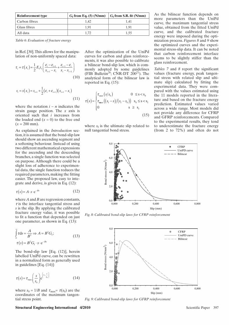
Structural Engineering International 4/2010 Scientific Paper 397
Reinforcement type Gf from Eq. (5) (N/mm) Gf from S.R. fi t (N/mm)
Carbon fibres 1,42 1,41
Glass fibres 1,91 1,91
All data 1,72 1,55
Table 6: Evaluation of fracture energy
in Ref. [30]. This allows for the manipu-lation of non-uniformly spaced data:
i ii i
i i
i i
i i
x E tx x x x
= ( ) = ++
+
12
1
1
1f f
11
(10)
s s x s x xi i i i i i i= ( ) = + +( )( )+ + +1 1 1
12
(11)
where the notation i − n indicates the strain gauge position. The x axis is oriented such that i increases from the loaded end (x = 0) to the free end (x = 200 mm).
As explained in the Introduction sec-tion, it is assumed that the bond-slip law should show an ascending segment and a softening behaviour. Instead of using two different mathematical expressions for the ascending and the descending branches, a single function was selected on purpose. Although there could be a slight loss of adherence to experimen-tal data, the single function reduces the required parameters, making the fitting easier. The proposed law, easy to inte-grate and derive, is given in Eq. (12):
s A s Bs( ) = e (12)
where A and B are regression constants, t is the interface tangential stress and s is the slip. By applying the calibrated fracture energy value, it was possible to fit a function that depended on just one parameter, as shown in Eq. (13):
τ
τ
d
e
f
f
sAB
A B G
s B G s Bs
02
2
2
∞
−
∫ = ⇒ =
( ) = ⋅ ⋅
;
(13)
The bond-slip law [Eq. (12)], herein labelled UniPd curve, can be rewritten in a normalized form as generally used in guidelines [Eq. (14)]:
sss
ss( ) = max
0
10e
(14)
where s0 = 1/B and t max= t (s0) are the coordinates of the maximum tangen-tial stress point.
After the optimization of the UniPd curves for carbon and glass reinforce-ments, it was also possible to calibrate a bilinear bond-slip law, which is com-monly adopted by some guidelines (FIB Bulletin26; CNR-DT 20021). The analytical form of the bilinear law is reported in Eq. (15):
s
s s
( ) =( ) <max 0 0 s s0
mmax s s s sf f 0 fs s s( ) ( )( ) <0
0 s sf
(15)
where sf is the ultimate slip related to null tangential bond stress.
As the bilinear function depends on more parameters than the UniPd curve, the maximum tangential stress value, obtained from the fitted UniPd curve, and the calibrated fracture energy were imposed during the opti-mization process. Figures 8 and 9 show the optimized curves and the experi-mental stress-slip data. It can be noted that carbon reinforcement interface seems to be slightly stiffer than the glass reinforcement.
Tables 7 and 8 report the significant values (fracture energy, peak tangen-tial stress with related slip and ulti-mate slip) calculated by fitting the experimental data. They were com-pared with the values estimated using the 11 models reported in the litera-ture and based on the fracture energy prediction. Estimated values varied across a wide range. Most models did not provide any difference for CFRP and GFRP reinforcements. Compared to the experimental results, they tend to underestimate the fracture energy (from 2 to 72%) and often do not
0,00,000 0,200 0,400
Slip (mm)
0,600 0,800
2,0
4,0
6,0
8,0
Bon
d st
rees
(N
/mm
2 )
CFRPUniPD curveBilinear
Fig. 8: Calibrated bond-slip laws for CFRP reinforcement
0,00,000 0,200 0,400
Slip (mm)
0,600 0,800
2,0
4,0
6,0
8,0
Bon
d st
rees
(N
/mm
2 )
CFRPUniPD curveBilinear
Fig. 9: Calibrated bond-slip laws for GFRP reinforcement
x056.indd 397x056.indd 397 10/25/10 4:22 PM10/25/10 4:22 PM
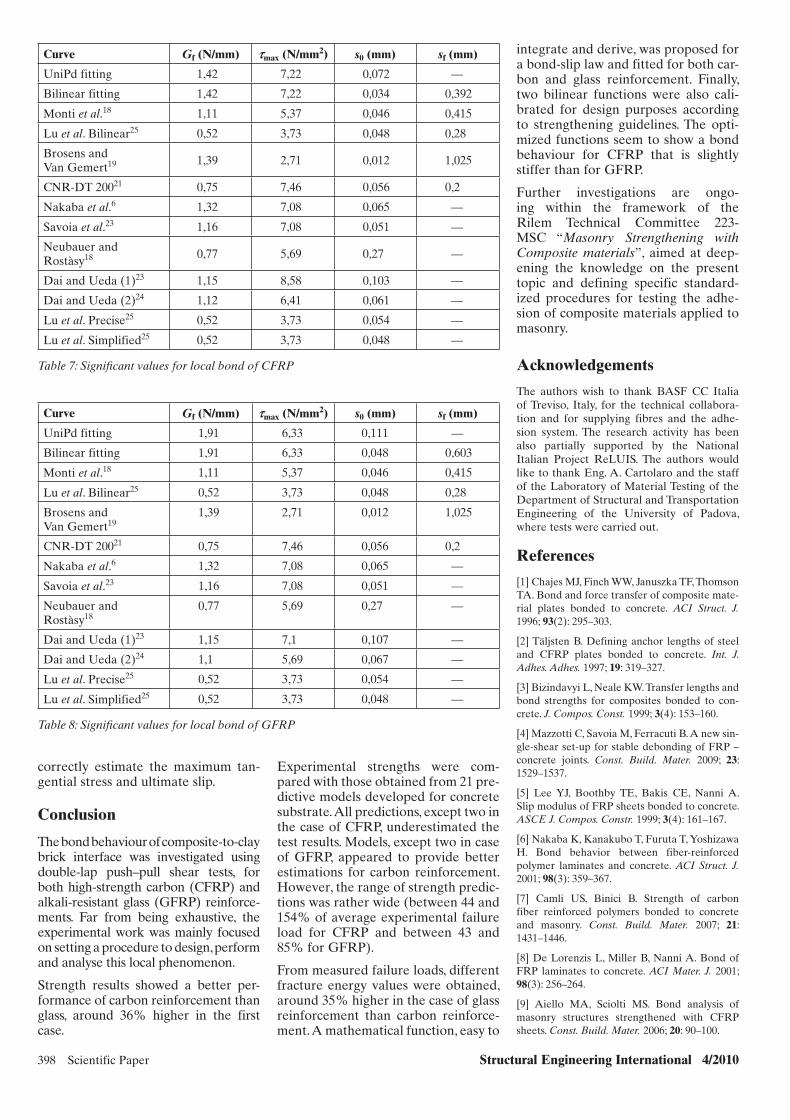
398 Scientific Paper Structural Engineering International 4/2010
Curve Gf (N/mm) smax (N/mm2) s0 (mm) sf (mm)
UniPd fitting 1,42 7,22 0,072 —
Bilinear fitting 1,42 7,22 0,034 0,392
Monti et al.18 1,11 5,37 0,046 0,415
Lu et al. Bilinear25 0,52 3,73 0,048 0,28
Brosens and Van Gemert19 1,39 2,71 0,012 1,025
CNR-DT 20021 0,75 7,46 0,056 0,2
Nakaba et al.6 1,32 7,08 0,065 —
Savoia et al.23 1,16 7,08 0,051 —
Neubauer and Rostàsy18 0,77 5,69 0,27 —
Dai and Ueda (1)23 1,15 8,58 0,103 —
Dai and Ueda (2)24 1,12 6,41 0,061 —
Lu et al. Precise25 0,52 3,73 0,054 —
Lu et al. Simplified25 0,52 3,73 0,048 —
Table 7: Signifi cant values for local bond of CFRP
Curve Gf (N/mm) smax (N/mm2) s0 (mm) sf (mm)
UniPd fitting 1,91 6,33 0,111 —
Bilinear fitting 1,91 6,33 0,048 0,603
Monti et al.18 1,11 5,37 0,046 0,415
Lu et al. Bilinear25 0,52 3,73 0,048 0,28
Brosens and Van Gemert19
1,39 2,71 0,012 1,025
CNR-DT 20021 0,75 7,46 0,056 0,2
Nakaba et al.6 1,32 7,08 0,065 —
Savoia et al.23 1,16 7,08 0,051 —
Neubauer and Rostàsy18
0,77 5,69 0,27 —
Dai and Ueda (1)23 1,15 7,1 0,107 —
Dai and Ueda (2)24 1,1 5,69 0,067 —
Lu et al. Precise25 0,52 3,73 0,054 —
Lu et al. Simplified25 0,52 3,73 0,048 —
Table 8: Signifi cant values for local bond of GFRP
correctly estimate the maximum tan-gential stress and ultimate slip.
Conclusion
The bond behaviour of composite-to-clay brick interface was investigated using double-lap push–pull shear tests, for both high-strength carbon (CFRP) and alkali-resistant glass (GFRP) reinforce-ments. Far from being exhaustive, the experimental work was mainly focused on setting a procedure to design, perform and analyse this local phenomenon.
Strength results showed a better per-formance of carbon reinforcement than glass, around 36% higher in the first case.
Experimental strengths were com-pared with those obtained from 21 pre-dictive models developed for concrete substrate. All predictions, except two in the case of CFRP, underestimated the test results. Models, except two in case of GFRP, appeared to provide better estimations for carbon reinforcement. However, the range of strength predic-tions was rather wide (between 44 and 154% of average experimental failure load for CFRP and between 43 and 85% for GFRP).
From measured failure loads, different fracture energy values were obtained, around 35% higher in the case of glass reinforcement than carbon reinforce-ment. A mathematical function, easy to
integrate and derive, was proposed for a bond-slip law and fitted for both car-bon and glass reinforcement. Finally, two bilinear functions were also cali-brated for design purposes according to strengthening guidelines. The opti-mized functions seem to show a bond behaviour for CFRP that is slightly stiffer than for GFRP.
Further investigations are ongo-ing within the framework of the Rilem Technical Committee 223-MSC “Masonry Strengthening with Composite materials”, aimed at deep-ening the knowledge on the present topic and defining specific standard-ized procedures for testing the adhe-sion of composite materials applied to masonry.
Acknowledgements
The authors wish to thank BASF CC Italia of Treviso, Italy, for the technical collabora-tion and for supplying fibres and the adhe-sion system. The research activity has been also partially supported by the National Italian Project ReLUIS. The authors would like to thank Eng. A. Cartolaro and the staff of the Laboratory of Material Testing of the Department of Structural and Transportation Engineering of the University of Padova, where tests were carried out.
References
[1] Chajes MJ, Finch WW, Januszka TF, Thomson TA. Bond and force transfer of composite mate-rial plates bonded to concrete. ACI Struct. J. 1996; 93(2): 295–303.
[2] Täljsten B. Defining anchor lengths of steel and CFRP plates bonded to concrete. Int. J. Adhes. Adhes. 1997; 19: 319–327.
[3] Bizindavyi L, Neale KW. Transfer lengths and bond strengths for composites bonded to con-crete. J. Compos. Const. 1999; 3(4): 153–160.
[4] Mazzotti C, Savoia M, Ferracuti B. A new sin-gle-shear set-up for stable debonding of FRP – concrete joints. Const. Build. Mater. 2009; 23: 1529–1537.
[5] Lee YJ, Boothby TE, Bakis CE, Nanni A. Slip modulus of FRP sheets bonded to concrete. ASCE J. Compos. Constr. 1999; 3(4): 161–167.
[6] Nakaba K, Kanakubo T, Furuta T, Yoshizawa H. Bond behavior between fiber-reinforced polymer laminates and concrete. ACI Struct. J. 2001; 98(3): 359–367.
[7] Camli US, Binici B. Strength of carbon fiber reinforced polymers bonded to concrete and masonry. Const. Build. Mater. 2007; 21: 1431–1446.
[8] De Lorenzis L, Miller B, Nanni A. Bond of FRP laminates to concrete. ACI Mater. J. 2001; 98(3): 256–264.
[9] Aiello MA, Sciolti MS. Bond analysis of masonry structures strengthened with CFRP sheets. Const. Build. Mater. 2006; 20: 90–100.
x056.indd 398x056.indd 398 10/25/10 4:22 PM10/25/10 4:22 PM

Structural Engineering International 4/2010 Scientific Paper 399
[10] Faella C, Martinelli E, Paciello S, Perri F. Composite materials for masonry structures: the adhesion issue. In MuRiCo 3: Proceedings of the 3rd Nat. Conf. on Mechanics of Masonry Structures Strengthened with Composite Materials: Modeling, Testing, Design, Control; 2009 April 1–3, Venice, Italy. Pitagora, Bologna, Di Tommaso A. (ed.), 2009; 266–273.
[11] Briccoli Bati S, Rovero L, Tonietti U. Adesione fra blocchi in laterizio e rinforzo in CFRP. In Proceedings of the National Workshop on Materiali ed Approcci Innovativi per il Progetto in Zona Sismica e la Mitigazione della Vulnerabilità delle Strutture, Faella C, Manfredi G, Piluso V, Realfonzo R (eds), Salerno, Italy. Monza: Polimetrica, 2007; 213–220.
[12] Panizza M. FRP Strengthening or Masonry Arches: Analysis of Local Mechanisms and Global Behaviour. Ph.D. [dissertation]. Padova (Italy): University of Padova; 2010.
[13] Basilio I. Strengthening of Arched Masonry Structures with Composite Materials. Ph.D. [dis-sertation]. Guimarães (Portugal): University of Minho; 2007.
[14] Subramanian K, Focacci F, Carloni C. An investigation on the interface fracture propa-gation between FRP and masonry. In MuRiCo 3: Proceedings of the 3rd Nat. Conf. on Mechanics of masonry structures strengthened with composite materials: modeling, testing, design, control; 2009 April 1-3, Venice, Italy. Pitagora, Bologna, Di Tommaso A (ed.), Bologna, 2009; 423–430.
[15] Capozucca R. Experimental FRP/SRP-historic masonry delamination. Compos Struct. 2010; 92(4): 891-903.
[16] Yao J, Teng JG, Chen JF. Experimental study on FRP-to-concrete bonded joints. Compos: B 2005; 36: 99–113.
[17] Chen JF, Teng JG. Anchorage strength mod-els for FRP and steel plates bonded to concrete. ASCE J. Struct. Eng. 2001; 127(7): 784–791.
[18] Lu XZ, Teng JG, Ye LP, Jiang JJ. Bond-slip models for FRP sheets-plates bonded to con-crete. Eng. Struct. 2005; 27: 920–937.
[19] Karbhari VM, Niu H, Sikorsky C. Review and comparison of fracture mechanics-based bond strength models for FRP-strengthened
structures. J. Reinforced Plastics Compos. 2006; 25(17): 1757–1794.
[20] Ferracuti B, Savoia M, Mazzotti C. Interface law for FRP—concrete delamination. Composite structures. 2007; 80(4), 523–531.
[21] CNR-DT 200/2004. Guide for the Design and Construction of Externally Bonded FRP Systems for Strengthening Existing Structures. Italian National Research Council: Rome, 2005.
[22] Savoia M, Ferracuti B, Mazzotti C. Non lin-ear bond-slip law for FRP-concrete interface. In: FRPRCS-6: Proceedings of the 6th International Symposium on Fibre-Reinforced Polymer Reinforcement for Concrete Structures; 2003 July 8–10; Singapore, Tan KH (ed.). World Scientific: Singapore, 2003; 1–10.
[23] Dai JG, Ueda T. Local Bond stress Slip rela-tions for FRP Sheets-Concrete Interfaces. In: FRPRCS-6: Proceedings of the 6th International Symposium on Fibre-Reinforced Polymer Reinforcement for Concrete Structures; 2003 July 8–10; Singapore, Tan KH (ed.), World Scientific: Singapore, 2003; 143–152.
[24] Dai JG, Ueda T, Sato Y. Development of the nonlinear bond stress-slip model of fiber rein-forced plastics sheet–concrete interfaces with a simple method. ASCE J Compos Const. 2005; 9(1): 52–62.
[25] Lu XZ, Teng JG, Ye LP, Jiang JJ. Bond-slip models for FRP sheet/plate-to-concrete interfaces. In: ACIC 2004: 2nd International Conference on Advanced Polymer Composites for Structural Applications in Construction; 2004 April 20–22; Guildford, Great Britain, Hollaway LC, Chryssanthopoulos MK, Moy SSJ (eds). Woodhead: Cambridge, 2004; 152–161.
[26] FIB Bulletin 14. Externally Bonded FRP Reinforcement for RC Structures. Fédération Internationale du Béton: Lausanne, 2001.
[27] Wu Z, Yuan H, Niu H. Stress transfer and fracture propagation in different kinds of adhe-sive joints. ASCE J. Eng. Mech. 2002; 128(5): 562–573.
[28] Savoia M, Ferracuti B, Mazzotti C. Una legge di interfaccia non lineare per placcaggi con lamine in FRP. In: AIMETA’03: Proceedings of the 16th Congress of Theoretical and Applied Mechanics; Sep 9–12; Ferrara, Italy, 2003.
[29] Täljsten B. Strengthening of concrete prisms using the plate bonding technique. Int. J. Fract. 1996; 82: 253–266.
[30] Valluzzi MR, Tinazzi D, Garbin E, Modena C. FEM modelling of CFRP strips bond behaviour for bed joints reinforcement techniques. In: STRUMAS VI: Proceeding of the 6th International Conference on Computer Methods in Structural Masonry; Sep 22–24; Rome, Italy, 2003.
Further Information
http://www.rilem.net/tcDetails.php?tc=223-MSChttp://www.cnr.it/sitocnr/Englishversion/CNR/Activities/RegulationCertification.htmlhttp://www.reluis.it/
List of Symbols
A Regression constantAf Cross-section area of a single stripB Regression constantbc Width of the concretebf Reinforcement widthb'f Width of a single strip c1 Regression constantc2 Regression constante Euler’s ConstantEc Modulus of elasticity of concreteEf Longitudinal modulus of elasticity of the
fibresGf Interface fracture energy in mode IILb Bonded lengthPu Failure loads Interface relative slips0 Interface slip at the maximum tangential
bond stresssf Ultimate interface slip at null tangential
bond stresstc Thickness of the concretetf Thickness of the fibresx Longitudinal abscissa along the bonded
lengthaT Constant valueaW Constant valuee Reinforcement strainsu Nominal tensile stresses at debondingt Tangential bond stresstmax Maximum tangential bond stress
x056.indd 399x056.indd 399 10/25/10 4:22 PM10/25/10 4:22 PM
400 Scientific Paper Structural Engineering International 4/2010
Peer-reviewed by international ex-perts and accepted for publication by SEI Editorial Board
Paper received: February 26, 2010Paper accepted: July 1, 2010
Bridges with Glass Fibre–Reinforced Polymer Decks: The Road Bridge in Friedberg, GermanyJan Knippers, Head of Institute, Universität Stuttgart, ITKE, Stuttgart, Germany; Eberhard Pelke, Head of Dept., Road and Traffic
Administrative Dept. Hessen, Wiesbaden, Germany; Markus Gabler, Research Assistant, Universität Stuttgart, ITKE, Stuttgart,
Germany; Dieter Berger, Development Eng., Road and Traffic Administrative Department Hessen, Wiesbaden, Germany.
Contact: [email protected]
As the “hub of Germany” due to its central position, the state of Hessen has the highest average volume of traffic in Germany. Durability and low maintenance of civil engineering structures are hence prerequisites in terms of maintaining the economy’s efficiency and reducing costs of citi-zens by keeping traffic congestions to a minimum. The first approaches were conducted by the administration by observing traditional bridge building.1 Today, project calculations of road construction include approximate life cycle costs. In order to implement the objectives mentioned above, dif-ferent new building techniques were examined and analysed. Lightweight constructions using fibre-reinforced polymer (FRP), which is very durable and fast to assemble, provide a poten-tial solution. Such a bridge system was recently developed and realised in the context of the project “Congestion-Free Hessen”.
Bridges with FRP Decks
Realised Constructions
The costs of FRP products are higher than that of conventional materials, therefore it is sensible to restrict their use to members that are susceptible to corrosion. For bridge superstructures, this means that decks can be built out of FRP, while the main girders are made of conventional materials such as steel and reinforced concrete (RC). This means not only lower costs but also less deflection of the superstructure due to the higher Young’s modulus of steel and RC. Steel FRP-composites have, especially in the USA, been exten-sively applied since the mid 1990s. The US Federal Highway Agency pres-ently counts approximately 70 bridges built with FRP decks.2 FRP decks are used very often in the refurbishment of existing road bridges. Damaged decks have been replaced on numer-ous RC-composite or steel bridges by FRP panels, whereas the abutment and the steel beams were preserved. The possibility of prefabricating large
lightweight panels and transporting them to the building site, allows for extremely rapid refurbishment and reopening of the bridges. The curing time necessary for concrete decks is a fundamental reason for choosing the application of FRP. Several road bridges with FRP decks have also been built in Korea in the last few years, the 300 m long and 35 m wide “Noolcha Bridge” in Busan, for exam-ple.3 Positive experience was thereby consistently gathered—no major dam-ages due to long term load have been observed in the structures built so far.4
Types of FRP Decks
Available FRP decks can generally be classified into two categories: pul-truded hollow sections and hand lay-up sandwich panels (Fig. 1). Pultruded decks consist of a row of prismatic bars that are manufactured through an automatic process. These hollow sec-tions have a wall thickness that varies from 5 to 15 mm and an overall dimen-sion of approximately 200 mm × 400 mm. Owing to the continuous manu-facturing process, the fibre direction is mostly longitudinal. The panels are formed by adhesively bonding the bars together. The bars are connected to the slab during assembly or previously at the factory in transportable sizes. The pultruded deck sections generally have a span of 2 to 3 m between the main girders.
On the other hand, sandwich panels bear loads in two directions with the same stiffness and are therefore bet-ter suited to carrying concentrated loads. However, bigger tolerances occur through the manual manufactur-ing process than in pultruded profiles. Furthermore, research has shown that, owing to minimal heat transfer in the sandwich panels, very high tempera-ture gradients can occur. Lastly, the intricate construction of connections and the connecting details are more challenging, which has led to sandwich panels not being introduced in Europe to date.
Abstract
In July 2008, the first road bridge in Germany using glass fibre-reinforced polymers (GFRP) was completed in Friedberg/Hessen. The structure has a span of 27 m and acts as a flyover across the federal road B3. The high durability of the new construction material and the fast assembly of the bridge were decisive factors in favour of GFRP.
During the preceding years, several lightweight bridges using FRP had been constructed in the USA, Japan and also in Europe. Through these projects, valuable experience was gath-ered regarding construction, and the use and performance of composites could be demonstrated.
The bridge in Friedberg extended this experience by taking into account the composite action between the FRP deck and the steel girders. It also followed, consequently, the approach of durable bridge construction by omit-ting any bearings or expansion joints and making the innovative material visible to passers-by.
Keywords: glass fibre-reinforced poly-mers; composites; road bridge; installa-tion; material tests; approval.
Introduction
The road and traffic administrative department in the German state of Hessen sees itself as a modern mobil-ity service provider. It consequentially supports the development of new building methods for civil engineering structures, providing sustainability and reduction of life cycle costs as well as minimal interference with traffic dur-ing the construction. This includes the application of new materials in build-ing methods.
x062.indd 400x062.indd 400 27/10/10 8:31 PM27/10/10 8:31 PM

Structural Engineering International 4/2010 Scientific Paper 401
girders (Fig. 3). A two-component epoxy adhesive was used to attach the FRP to the steel. The deck con-sisted of glued hollow sections and had a structural height of 225 mm. It was covered by a 45 mm thick layer of polymer concrete with applied polymer surfacing, which was sprayed with silica to provide surface rough-ness. The tensile strength of the poly-mer concrete was high enough to be considered in the calculation as strengthening for the top flange of the FRP deck. To obtain sufficient load-bearing safety, such composite action was necessary for withstanding con-centrated wheel loads. The edge cas-ings were made with a second layer of the same FRP sections. These casings together with the steel railing guaran-tee the required safety for the cars on the bridge. The design velocity of the road passing over the bridge is V ≤ 50 km/h. The railing itself was connected to the front faces with anchor plates that were glued into the hollow sec-tions of the FRP profiles of the deck and edge casings. Thus, it is possible to replace these parts in case of dam-age. The front face of the FRP decks was closed with thin-walled plates in order to prevent vermin from enter-ing the hollow sections (Fig. 4).
After assembling, the entire super-structure was rigidly connected onto the concrete abutments by grout-ing the attached fixing plates with welded head stud bolts. Making the FRP parts visible for passers-by was of utmost importance; therefore the front faces of the FRP deck remained uncovered, the hollow parts being recognisable as shadow gaps. The frame appearance of the bridge was underlined by the choice and orienta-tion of formwork.
Finite Element Method (FEM)—Calculations and Laminate Analysis
The bridge structure was designed as a restrained frame with linear structural members. The composite cross section of the superstructure was therefore represented as an ideal steel cross sec-tion. It was already known from avail-able test results6 that full composite action can be assumed for the adhe-sive layer and the deck as the cross section virtually stayed even. With the actual dimensions of the Friedberg superstructure, the entire width of the FRP deck is under compression in the centre span. Owing to the direc-tion of the fibre reinforcement, the
Fig. 1: Comparison of different systems for FRP bridge decks; (left): pultruded hollow sec-tions; (right): manually laid-up sandwich panels
Dimensioning and Building
Draft Principles
Unlike the case of previously built structures, the aim of the design for the new road bridge in Friedberg, Germany, was to fully apply the com-posite action between the steel girders and the FRP deck, and to verify this experimentally as well as through anal-ysis. For this reason, an adhesive layer was chosen for the FRP–steel connec-tion: a joining method so far rarely used for civil engineering structures, although the material is appropriate and enables smooth load transmission without weakening caused by drilling. A frame structure was chosen with the purpose of long life and low upkeep of the construction, and therefore, track transition and bridge bearings were
omitted. The structure was designed according to the ENV 1991–35 taking into account the government regu-lations of Germany. Due to lack of appropriate data, the fatigue-proof test of FRP could not be carried out through calculation. It was substituted by test data from the manufacturer of the FRP deck, which certified advanta-geous fatigue behaviour.
Structural System and Composition
The bridge structure (Fig. 2) has an integral design with a span of 27 m over the two-lane federal road B3a near Friedberg, in central Germany. The superstructure was made of two slightly curved and haunched steel girder with a structural height of 625 to 900 mm. The overall 5 m wide FRP deck was glued onto both main
900
8290
625
7000 20000 7000
Fig. 2: FRP bridge in Friedberg (Hessen—Germany); (top): elevation; (bottom): longitudi-nal section (Units: mm)
x062.indd 401x062.indd 401 27/10/10 8:31 PM27/10/10 8:31 PM
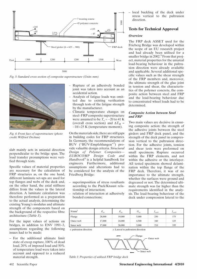
402 Scientific Paper Structural Engineering International 4/2010
– Rupture of an adhesively bonded joint was taken into account as an accidental action.
– Analysis of fatigue loads was omit-ted due to existing verifi cation through tests of the fatigue strength by the manufacturer.
– Climatic temperature changes on steel–FRP composite superstructure were assumed to be Te = −20 to 41 K (overall cross section) and ΔTM = −18/+25 K (temperature moment).
On the materials side, there are still gaps in building codes for FRP structures. In Germany, the recommendations of BUV (“BUV-Empfehlungen”7) pro-vide valuable design criteria. Structural Design of Polymer Composites—EUROCOMP Design Code and Handbook8 is a helpful handbook for engineers. Furthermore, additional assumptions and alterations had to be considered for the analysis of the Friedberg Bridge:
– superimposition of stress resultants according to the Puck/Knaust rela-tionship of interaction;
– relation of interaction at adhesively bonded connections;
slab mainly acts in uniaxial direction perpendicular to the bridge span. The load transfer presumptions were veri-fied through tests.
Specific values of material properties are necessary for the calculation of FRP structures as, on the one hand, different laminate set-ups are used for top flanges and webs of the deck and, on the other hand, the axial stiffness differs from the values in the lateral direction. A laminate calculation was therefore performed as a preparation to the actual analysis, determining the existing Young’s modulus and ultimate strength of the components based on the background of the respective fibre architecture (Table 1).
For the input values of actions on bridges, in addition to ENV 1991–3, assumptions regarding the following issues had to be made:
– For the additional ultimate limit state of creep rupture, 100% of dead load, 20% of imposed load and 50% of temperature load were taken into account and opposed to a reduced material strength.
East
45 polymer concrete
7 wearing course
Steel girder (h = 625 ... 900)
West13001200 12001300
1000
+45
+2454%
2,5%
+155
– 45
5000
FRP-deck
Fig. 3: Standard cross section of composite superstructure (Units: mm)
Fig. 4: Front face of superstructure (photo credit: Wilfried Dechau)
Inner web
Outer webFlange
N/mm2 Exx Eyy Gxy fx,u,k fy,u,k
Flange 28,000 19,000 5,000 250 175
Outer web 17,000 24,000 4,500 160 125
Inner web 17,000 26,000 3,000 210 195
x: pultrusion direction y: Lateral to pultrusion direction
Table 1: Properties of utilised FRP bridge deck
– local buckling of the deck under stress vertical to the pultrusion direction.
Tests for Technical Approval
Overview
The FRP deck ASSET used for the Frieberg Bridge was developed within the scope of an EU research project and had already been utilised for a smaller bridge in 2002.9 From that proj-ect, material properties for the uniaxial load-bearing behaviour in the pultru-sion direction were already available and applicable. Several additional spe-cific values such as the shear strength of the FRP members and, moreover, the ultimate strength of the glue joint in tension and shear, the characteris-tics of the polymer concrete, the com-posite action between steel and FRP and the load-bearing behaviour due to concentrated wheel loads had to be determined.
Composite Action between Steel and FRP
Two main values are decisive in ensur-ing composite action: the strength of the adhesive joints between the steel girders and FRP deck panel, and the strength of the deck panel in compres-sion vertical to the pultrusion direc-tion. For the adhesive joints, tension and shear tests were preformed on small specimens. Rupture occurred within the FRP elements, and not within the adhesive or the interlayer. All tested specimens showed delami-nation within the top flange of the FRP deck. Therefore, it was of no importance to the ultimate strength, whether the surfaces were ground and degreased or not. The determined ulti-mate strength was far higher than the requirements identified in the analy-sis. The load-bearing behaviour of the deck under compression lateral to the
x062.indd 402x062.indd 402 27/10/10 8:32 PM27/10/10 8:32 PM

Structural Engineering International 4/2010 Scientific Paper 403
The surfacing system and the top flange of the FRP deck are assumed to be in composite action. Thus, the stress is distributed over a larger area. In addition, the polymer concrete sur-facing reinforces the FRP deck flange (Fig. 6). This approach is similar to the design concept for orthotropic steel superstructures. The system is stable for wheel loads according to ENV 1991–3.
Construction and Assembly of the Superstructure
Pre-Assembly in Shop
The entire superstructure was pre-assembled in a storehouse located 20 km from the building site. This allowed for protection against weathering and guaranteed optimal working condi-tions. The steel beams had already been welded when delivered and fur-nished with corrosion protection in the hall. The FRP deck had already been partially glued by the manufacturer and delivered in 5,00 × 1,50 m courses. The bonding of the deck panels onto the steel beams could be performed within 1 week. The FRP was ground and cleaned directly before the bond-ing; the adhesively bonded joints of the steel beams had already been sandblasted.
On completion of the deck, the edge casings were affixed with a second layer of FRP sections and the front face was closed. After that a 45 mm thick layer of polymer concrete was applied onto the FRP. In the wet con-dition, the chosen coating was very stiff and debris-like and had to be levelled with appropriate tools to a nominal thickness. The treatment of the surfacing in one working sequence without joints proved to give the best results. The final jobs were the mount-ing of the railings, the edge sections at the transition between superstructure and abutment and the casting of 5 mm thick polymer surfacing on the edge casings.
Transportation, Lifting and Positioning of the Superstructure
Transporting the bridge to the build-ing site had to be done in one night, as the public road next to the assem-bly hall could only be blocked for that long. The bridge was transported to the building site on a low platform trailer at a maximum speed of 50 km/h. The total weight of the superstructure was
between the individual elements. The failure mode became decisive for the design of the bridge. An optimization of the cross section, especially around the joining area could increase the compression strength perpendicular to the direction of pultrusion.
Concentrated Wheel Loads
Stress concentrations due to concen-trated wheel loads are critical for the thin walls of the FRP deck. The poly-mer concrete used for the surfacing can bear tension and shear stresses.
pultrusion direction has already been described within the context of other research work.6 Analogue experiments were conducted in order to confirm the values and secure a wider data basis. Therefore a 750 × 600 mm section of the deck was tested in an upright posi-tion under central load up to the point of rupture (Fig. 5). Because of local buckling, the strength was consider-ably lower than what could have been expected from the laminate architec-ture. The buckling appeared within the reinforcing layers of the overlap joint
0
100
200
300
400
500
600
700
0 1 2 3 4 5 6 7
Deformation (mm)
Nor
mal
forc
e on
a 6
00 m
m w
ide
spec
imen
(kN
)
Fig. 5: Test set-up and results for determination of compressive strength of FRP—bridge deck perpendicular to the direction of pultrusion
–175
–150
–125
–100
–75
–50
–25
0–8–7–6–5–4–3–2–10
Deflection (mm)
Loa
d on
a a
rea
of 4
00 ×
200
mm
(kN
)
With surfacing
Without surfacing
Fig. 6: Test set-up and results for concentrated wheel loads, with and without surfacing layer
x062.indd 403x062.indd 403 27/10/10 8:32 PM27/10/10 8:32 PM

404 Scientific Paper Structural Engineering International 4/2010
[8] Clarke J, et al. Structural Design of Polymer Composites—EUROCOMP Design Code and Handbook. E&FN SPON: London, 1996.
[9] Luke S, et al. Advanced composite bridge decking system—project ASSET. Struct. Eng. Int. 2002; 12: 76–79.
close attention to detailed specifications of technical details in the tender docu-ments and during construction proved to be beneficial. Thus, the necessary execution excellence could be obtained and risks for the principal could be minimised. With good collaboration between the consultant and the public authority, and a high commitment from all parties involved, this project could be completed successfully.
References
[1] Kuhlmann U, Pelke E, et al. Ganzheitliche Wirtschaftlichkeitsbetrachtungen bei Verbund-brücken. Stahlbau 76 (Heft 2), Seite 105ff, Germany.
[2] Webpage of Federal Highway Administration (USA). www.fhwa.dot.gov/Bridge/FRP (as on Aug.16, 2010).
[3] Lee SW, Kee-Jeung H. Experiencing More Composite-Deck Bridges and Developing Innovative Profile of Snap-Fit Connection. COBRAE Conference, Stuttgart, 2007.
[4] Keller T, et al. Long-term performance of a glass fiber-reinforced polymer truss bridge. J. Compos. Constr. (ASCE) 01/2007, Vol. 11, pp.99–108.pp.99.
[5] ENV 1991–3 Traffic Loads on Bridges.
[6] Gürtler H. Composite Action of FRP Decks adhesively bonded to Steel Main Girders. PhD thesis No. 3135, Prof. Thomas Keller, EPFL Lausanne (CH), CCLab, 2004.
[7] BÜV-Empfehlung. Tragende Kunststoff-bauteile im Bauwesen (TKB). Bau-Überwachungsverein e.V., 2002 (Entwurf).
approximately 60 tons. The total width of the carriage was only 5 m; support vehicles were not necessary and the motorway was not closed. The super-structure was lifted the next morning within 2 h onto the abutments (Fig. 7) by two truck-mounted cranes, after which the prepared supporting pock-ets were grouted (Fig. 8). With this completed, only the finishing jobs on the abutments were pending before the bridge could be made operational.
Conclusion
The use of fibre composites has great potential in bridge building. The pos-sibility of pre-assembling in the hall allows for rapid installation on site. In this project, the critical working stages of gluing the FRP panels, as well as the lifting and positioning of the superstructure were performed with-out any problems. The handling of the prefabricated products is relatively non-sensitive. Detailed recording and tracking the quality of important components and working stages in the tender documents proved to be worthwhile.
Monitoring the bridge over the next few years should contribute to gather-ing experience and optimising building methods for FRP bridge decks. Paying
Fig. 7: Mounting of superstructure on con-struction site (photo credit: Fiberline Com-posites A/S, Denmark)
Fig. 8: Superstructure being lowered shortly before settling down in the grouting—pocket (photo credit: ASV Gelnhausen, Germany)
SEI Data BlockEI Data Block
Owner: State of Hessen, Germany in the representation of Federal Republic of Germany
Designer: Knippers Helbig Advanced Engineering, Stuttgart – New York
Material tests and monitoring: Universität Stuttgart, Institute for Building Structures and Structural design (itke), Stuttgart (D)
Design Construction Phase:KHP Planungsgesellschaft
Main contractor: LS Bau GmbH & Co. KG, Giessen (D)
FRP fabricator: Fiberline Composites A/S, Middelfart (DK)
FRP (t): 13,5
Span lengths (m): 27,0
Construction cost (EUR million): 0,55
Service date: August 2008
x062.indd 404x062.indd 404 27/10/10 8:32 PM27/10/10 8:32 PM

Structural Engineering International 4/2010 Technical Report 405
Current and Future Applications of Glass-Fibre-Reinforced Polymer Decks in KoreaSung Woo Lee, President, Prof., Kookmin University, Seoul, Korea; Kee Jeung Hong, Prof., School of Civil Eng. Kookmin
University, Seoul, Korea; Sinzeon Park, Associate Manager, Kookmin Composite Infrastructure Inc., Kyungki-do, Korea.
Contact: [email protected]
they have been used successfully to replace conventional concrete and steel decks on a number of bridges. The GFRP composite decks for bridges have significant advantages compared to conventional concrete and steel decks as they are highly durable and corrosion free. Much longer service lives and lower maintenance costs are expected for GFRP composite decks than for conventional concrete and steel decks, which will, in most cases, result in much lower life-cycle cost (LCC). The lightweight of GFRP com-posite decks reduces the dead load by as much as 80% compared to conven-tional concrete decks. Much slimmer substructures are possible for bridges on account of the use of lightweight GFRP composite decks. When a GFRP composite deck is used for re-decking of a bridge, the capacity for live load on the bridge is consequently upgraded without strengthening its substruc-tures. Furthermore, since GFRP com-posite decks can be installed easily and quickly, the duration of construction reduces significantly and the amount of disruption to traffic lessens. This allows considerable savings in direct and indi-rect costs to the urban community.
In view of these notable advantages of GFRP composite decks, numerous studies have been carried out and an increasing number of field applica-tions have been reported.1,2 Moreover, many profiles of GFRP composite decks have been developed and put into practice since the 1990s.2 In recent times, Korea has become one of the leading countries in the construction of composite-deck bridges. In Korea, more than 30 bridges (road and foot-bridges) with GFRP composite decks have been constructed. The “Noolcha Bridge” in the Busan Newport area was constructed with the world’s larg-est (300 m long and 35 m wide) com-posite-deck panel, and the 1,7 km-long walkway of the “Hangang Bridge” in Seoul was expanded from a width of 2,5 to 5 m by replacing the existing concrete decks with the composite decks. Many more bridges with GFRP
composite decks are scheduled to be constructed.
The GFRP composite decks with tongue-and-groove connections were developed and commercialised by the authors’ university and a private com-pany.3 Subsequently, the snap-fit con-nections of GFRP composite decks have been invented to significantly improve the construction quality and reduce the installation time compared to tongue-and-groove connections of GFRP composite decks.4–11
Developed GFRP Composite Decks
Tongue-and-Groove Composite Decks
Through extensive studies such as flex-ural tests, compressive fatigue tests, flexural fatigue tests, shear connection tests, traffic barrier tests, pavement bonding test, accelerated chemical tests and field load tests, a composite-deck profile that uses a tongue-and-groove connection was developed. As shown in Fig. 1a, it has three trapezoi-dal cells 200 mm in height (TG200), and is fabricated by pultrusion. To fabricate the laminate of the deck, 8800 Tex E-glass rovings are used in the longitudinal direction in conjunc-tion with multi-axial stitched fabrics (90°, ±45°), and unsaturated polyes-ter is used as a resin base. The deck is designed for typical girders spaced at 2,5 to 3,0 m under the DB24 truck load (front and rear wheel loads are 24 and 96 kN, respectively) according to the Korean Highway Bridge Design Specifications.12 The pultruded deck tubes are horizontally assembled by epoxy bonding to build deck panels for bridges as shown in Fig. 2a.
Snap-Fit Composite Decks
Use of the tongue-and-groove connec-tion method is prevalent in the assem-bly of composite decks, but it causes two problems when used for bridge decks. For conventional construction
Abstract
In comparison to concrete or steel bridge decks, glass-fibre-reinforced polymer (GFRP) compos ite bridge deck is highly economical, since its lightweight property reduces initial construction cost for the foundation, and the high durability decreases the life-cycle cost for the bridges. Furthermore, the duration of construc-tion is reduced significantly because of the short installation time of the light-weight GFRP composite decks.
Korea is one of the leading countries in the construction of composite-deck bridges in recent years. In Korea, 13 road bridges (deck area = 15 917 m2) have been constructed and six more road bridges (deck area = 9747 m2) will be constructed in the near future. Furthermore, 19 footbridges (deck area = 14 921 m2) have been constructed to date and six more footbridges (deck area = 14 204 m2) will be constructed in the near future. Among them, there are two remarkable projects: the Noolcha Bridge in Busan Newport which was constructed with the world’s largest composite-deck panel, which is 300 m long and 35 m wide, and the existing 1,7 km-long walkway of the Hangang Bridge in Seoul which was expanded from a width of 2,5 to 5 m by replacing the existing concrete decks with com-posite decks.
Keywords: GFRP; composite deck; road bridge; footbridge; walkway expansion; snap-fit.
Introduction
To cope with the problems of deteriora-tion and corrosion in conventional steel and concrete materials, highly durable and lightweight fibre-reinforced poly-mer (FRP) composites are considered to be one of the most promising alter-native materials for civil infrastruc-tures. Among many applications of these materials, glass-fibre-reinforced polymer (GFRP) composite decks for bridges are particularly notable, since
x058.indd 405x058.indd 405 27/10/10 8:41 PM27/10/10 8:41 PM

406 Technical Report Structural Engineering International 4/2010
with concrete decks, shear connectors are installed on top of the girder prior to the placement of the concrete decks. For construction with the tongue-and-groove composite decks, in contrast, shear connectors cannot be installed before the placement and assembly of the composite decks on girders, since the composite decks are assembled by horizontal sliding on the top surface of the girder. Small holes at the locations of the shear studs must therefore be made on the composite decks prior to placing the composite decks on gird-ers. After the placement and assembly of the composite decks, the shear studs are welded to the steel girders (or steel plates attached on the concrete girders) through small holes. Welding shear studs to girders through small holes is diffi-cult and time-consuming and can result in poor welding quality. Accumulated horizontal gaps between the assembled composite decks become larger for a longer bridge. If the accumulated gaps are significantly large, it can cause mis-matches between the locations of shear studs and the locations of the associated holes. This is the second problem that may produce construction errors and an increase in the construction time.
To resolve the aforementioned problems related to conventional
tongue-and-groove connections, new profiles of composite decks with snap-fit connections have been developed. The developed composite decks are assembled by mechanical snap-fit-ting in the vertical direction (Fig. 2b). Figure 1b shows the pultruded com-posite decks (SF200) with snap-fit connections for road bridges, which are not used yet in the field and are still under verification. Other snap-fit profiles have also been developed such as SF75L, SF75H, SF100 and SF125, which are not discussed in this paper explicitly. However, they are success-fully applied in 19 footbridges in Korea in view of the easy assembly of the composite decks on the girder. The dif-ferences between these profiles lie in the height of the profile and the thick-ness of the flanges and webs.
The newly developed snap-fit com-posite decks significantly improve workability and quality in welding shear studs to girders since the shear studs are welded with enough working space before placement of the com-posite decks. Furthermore, the devel-oped decks help to avoid mismatches between the locations of shear studs and the locations of associated holes on the composite decks, since the horizontal gaps between the snap-fit
composite decks are rather limited and predictable. If the snap-fit com-posite decks are assembled without adhesive bonding, they can be easily disassembled and reused. The snap-fit connections also help to reduce the installation time and associated work-ing costs.
Projects Examples
Road Bridges
The developed composite decks with tongue-and-groove connections at a height of 200 mm (Fig. 1a) have been applied for the construction of road bridges in Korea, with different girder types such as steel-plate girders, steel-box girders, pre-stressed concrete gird-ers and reinforced concrete girders. 13 road bridges (deck area = 15 917 m2) have been constructed and six more road bridges (deck area = 9747 m2) are planned to be constructed. Among these applications, the Bongsan Third Bridge and the Noolcha Bridge are shown in Figs. 3 and 4, respectively. The 36 m long and 7 m wide compos-ite-deck panel was assembled on the steel-plate girders for the Bongsan Third Bridge as shown in Fig. 3a, con-struction on the bridge was completed in 2007. The Noolcha Bridge con-structed in 2006 at the Busan Newport is considered a milestone since it has the world’s largest composite deck. Figure 4a shows the placing of the composite-deck panel from the storage site onto the RC girders using a crane for the Noolcha Bridge. Placing a sin-gle composite-deck panel (2 × 17,5 m) takes approximately 2 minutes, which is a significant reduction in construc-tion time over that required for the placing of conventional concrete- or steel-deck panels. This quick instal-lation of decks is a significant advan-tage in using the composite decks for bridge construction. Furthermore, the construction costs for the marine piles were significantly reduced because of the lightweight of the composite decks. Asphalt was used for the pavement of the Noolcha Bridge.
Footbridges and Walkway Expansion
The recently developed composite decks TG200, SF75L, SF75H, SF100 and SF125 have been applied exten-sively for the construction of foot-bridges in Korea. These footbridges are constructed in short time periods as compared with conventional con-crete- or wood-deck footbridges, since
(a) Tongue-and-groove connection (TG200) (b) Snap-fit connection (SF200)
Fig. 1: Pultrusion of composite decks
(a) Tongue-and-groove connection (TG200)
(b) Snap-fit connection (SF200)
Fig. 2: Connections for composite decks
x058.indd 406x058.indd 406 27/10/10 8:41 PM27/10/10 8:41 PM

Structural Engineering International 4/2010 Technical Report 407
the developed composite decks are much easier to install. 19 footbridges (deck area = 14 921 m2) have been constructed and six more footbridges (deck area = 14 204 m2) are planned for construction.
In 2006, the developed composite decks (SF100) were quickly assembled at high elevation for a suspension foot-bridge, called the Wolchul Mountain Bridge. Shown in Fig. 5, it is 53 m long and 1 m wide. The 1,7 km-long walkway
of the Hangang Bridge in Seoul was upgraded with ease by replacing the existing concrete decks with the light-weight composite decks (SF75L). The existing walkway, which was 2,5 m in width, was expanded to 5 m through this upgrade without strengthening the substructures. After the existing concrete decks had been removed, Fig. 6a shows placing of the compos-ite decks for the expanded walkway on both sides of the Hangang Bridge. The red lane for bikes and the grey lane for pedestrians are shown in Fig. 6b. Based on these successful applications of composite decks, more projects for new bridges and walkway expansions have been scheduled.
Conclusion
GFRP composite decks have been widely applied for many road bridges and footbridges in Korea. Among these GFRP deck bridges, there are two remarkable projects: the Noolcha Bridge in Busan Newport has been constructed with the world’s larg-est composite-deck panel and the Hangang Bridge in Seoul, has been expanded with ease from a width of 2,5 to 5 m by replacing the existing con-crete decks with the composite decks.
The newly developed snap-fit connec-tion of the composite decks resolves two problems encountered during construc-tion with the tongue-and-groove com-posite decks: poor welding conditions for the connection of the shear studs and the possible mismatch between the loca-tions of shear studs and the associated locations of pre-drilled holes on the composite decks. By snap-fitting com-posite decks without adhesive bonding, simplified assembly and disassembly of the composite decks are ensured. This enables their application in temporary bridges or temporary roads. It is antici-pated that the newly developed snap-fit connection will pave the way for far wider applications of GFRP composite decks in future, and that GFRP com-posite decks will be promising alterna-tives to c onventional concrete, steel or wood decks for bridges.
References
[1] DARPA. Advanced Composites for Bridge Infrastructure Renewal-Phase II Tasks 16- Modular Composite Bridge. Defense Advanced Research Projects Agency. Technical Report Vol. IV. USA, 2000.
[2] Keller T. Use of Fiber Reinforced Polymers in Bridge Construction. Structural Engineering Documents 7. IABSE (International Association
(a) Placing GFRP composite decks (TG200) (b) Completed bridge
Fig. 3: Bongsan Third Bridge (steel-plate girder bridge)
(a) Placing GFRP composite decks (TG200) (b) Completed bridge
Fig. 4: Noolcha Bridge (RC girder bridge)
(a) Placing GFRP composite decks (SF100) (b) Completed bridge
Fig. 5: Wolchul Mountain Bridge (suspension bridge)
(a) Placing GFRP composite decks (SF75L) (b) Completed walkway (four side-lanes)
Fig. 6: Walkway expansion of Hangang Bridge (arch bridge and steel-plate girder bridge)
x058.indd 407x058.indd 407 27/10/10 8:41 PM27/10/10 8:41 PM

408 Technical Report Structural Engineering International 4/2010
for Bridge and Structural Engineering). Switzerland, 2003.
[3] Lee SW. Development of High Durable, Light Weight and Fast Installable Composite Deck. MOCT R&D Report. Ministry of Construction and Transportation, Korea, 2004.
[4] Lee SW. Fiber Reinforced Polymer Composite Bridge Deck of Tubular Profile Having Vertical Snap-Fit Connection. US Patent No. US 7, 131, 161 B2, USA; 2006.
[5] Lee SW, Hong KJ. Development of Composite Deck Connection for Pedestrian Bridge Using Korean Traditional Wooden Joint Method. KOSEF Research Report. Korean Science and Engineering Foundation, Korea, 2007.
[6] Lee SW, Hong KJ. Experiencing more com-posite-deck bridge and developing innovative profile of snap-fit connections. Proceedings of COBRAE Conference. Stuttgart, Germany, 2007.
[7] Lee SW, Hong KJ. Constructing bridges with glass-fiber reinforced composite decks. Proceedings of 4th International Structural Engineering and Construction. RMIT University, Melbourne, Australia, 2007.
[8] Lee SW, Hong KJ. Evolution of innovative snap-fit connection for pultruded ‘Delta Deck’. Proceedings of European Pultrusion Technology Association. Rome, Italy, 2008.
[9] Lee SW, Hong KJ. Experiencing more GFRP composite bridge decks for vehicular
and pedestrian bridges. Proceedings of IABSE. Chicago, USA, 2008.
[10] Lee SW, Hong KJ, Ketel J. Composite ‘Delta Deck’ of innovative snap-fit connection for new and rehabilitated footbridges. Proceedings of Footbridge 2008. Porto, Portugal, 2008.
[11] Lee SW, Hong KJ. Development of Light-Weight Composite Deck with Snap-Fit Connection for Rigmat and Bridge Deck. MOCT R&D Report. Ministry of Construction and Transportation. Korea, 2009.
[12] Korea Road and Transportation Association. Korean Highway Bridge Design Specifications. Ministry of Construction and Transportation, Korea, 2005.
SED 7 - Structural Engineering Document on FRP
www.iabse.org/publications/onlinshop
Topics: Overview and Classification, Fibres and Matrices, Tensile Elements,
Structural Components and Systems, FRP-Reinforced Concrete – State-
of-the-Art, Fibre Reinforced Polymers – State of the Art in Repair and
Strengthening, Fibre Reinforced Polymers – State-of-the-Art in Hybrid
New Structures, Fibre Reinforced Polymers – State-of-the-Art in All-
Composite New Structures, Design, Codes and Guidelines, Application
Recommendations, Research, Requirements and Recommendations.
Price: CHF 40 for Members, CHF 70 for Non-Members
This Structural Engineering Document reviews the progress made
worldwide in the use of fibre reinforced polymers as structural
components in bridges until the end of the year 2000. It includes
application and research recommendations with particular reference
to Switzerland and is aimed at both students and practising engineers,
working in the field of fibre reinforced polymers, bridge design,
construction, repair and strengthening.
IABSE
x058.indd 408x058.indd 408 27/10/10 8:42 PM27/10/10 8:42 PM

Structural Engineering International 4/2010 Technical Report 409
Field Issues Associated with the Use of Fiber-Reinforced Polymer Composite Bridge Decks and Superstructures in Harsh EnvironmentsLouis N. Triandafilou, P.E., M.ASCE, Senior Structural Eng., Federal Highway Administration Resource Center, Baltimore, MD,
USA and Jerome S. O’Connor, P.E., F. ASCE, Manager, Bridge Engineering Program, Dept. of Civil, Structural, Environmental
Engineering, University at Buffalo, The State University of New York, Buffalo, NY, USA. Contact: [email protected]
should be encouraged. By making this knowledge available to a wide range of owners, engineers, and researchers, cooperation can be brought about in the development of the modifications to design and construction practices that will help advance the state of the art and the use of composites in practice.
The scope of the discussion herein is restricted to 117 identified structures that have utilized FRP for the bridge deck or the superstructure. Although a few of these structures are too short to meet the federal definition of a bridge (at least 6,1 m), they are being considered here, since the lessons are the same, regardless of span length. Also included are the decks that have been taken out of service because of operational problems, and FRP super-structures that use concrete, timber, or asphalt for the deck or wearing sur-face. Experience from these bridges has provided lessons pertaining to the fabrication of the FRP, application of the wearing surface, and their long-term performance under harsh envi-ronmental conditions. Excluded from the discussion are pedestrian bridges, timber glue-laminated bridges that use FRP as a laminate, and FRP stay-in-place (SIP) forms for a concrete deck.
Performance Summary
Of the installations considered in this study, 95% are still in service and beingmonitored visually as part of regularly scheduled bridge inspections. Six have been taken out of service because of structural defects or failures of the deck or superstructure panels. An undisclosed number have also exhib-ited problems such as cracking and spalling of an adhesively bonded wear-ing surface.
Structural Integrity
It is often difficult to state conclusively what caused a particular structural failure. The six products taken out of
service were from various manufactur-ers and manufacturing techniques.
– Two types of deck were removed from the Salem Avenue bridge in Ohio (one vacuum-assisted resin transfer molded (VARTM), and one hand-laid sandwich section), because the FRP fl ange had sepa-rated from the FRP web core. There may have been contributing factors that led to failure of the decks after the bridge was placed in service, but an initiator of the problems seems to have been a manufacturing defect. The connection between the decks and the steel beams may have also played a role by allowing too much movement under live loads.
– A detour bridge in Iowa was taken out of service and is not being used because it is not considered structur-ally sound. It is a VARTM sandwich section that separated between the FRP fl ange and web (top face skin and core). This could have been caused by a manufacturing defect or possibly by pounding from truck traffi c along the leading edge after it was placed in service. The impact was apparently due to a slight height difference between the deck surface and the approach pavement.
– In West Virginia, two corrugated core decks from the same manufac-turer have been taken out of service because of structural integrity issues with the hand lay-up sandwich sec-tion. On one, clips between the deck and steel fl oor beam failed, allowing excessive movement that apparently led to a crushing of the web core of the deck. On the other, there were leaking joints between panels, and apparent debonding of the top face skin and crushing of the FRP core that resulted in “potholes”.
– A pultruded FRP deck was removed from a bridge in Oregon owing to unsatisfactory performance of the support and connection details. The connection, which was designed to be rigid between the FRP deck and the steel structure, did not serve as
Abstract
There has been ample time for the United States to evaluate the use of fiber-reinforced polymer (FRP) com-posites to serve as bridge decks and superstructures under real-world envi-ronmental and operating conditions. This provides a great opportunity to weigh in on the decision to move for-ward with these materials. By studying the successes and failures, materials and techniques used for the design and construction of these bridges can be improved so that we can move closer to the goals of maintenance-free bridges and service lives exceeding 100 years. Though only a few of these structures are instrumented for structural health monitoring, there are a sufficient num-ber of lessons that can be gleaned from the experiences of various owners dur-ing the fabrication, installation, opera-tion, and inspection of these structures. By addressing these issues head-on, advocates will be better equipped to have direct dialogue with those in the profession who remain skeptical about the hidden potential for a construction material that is strong, light, and corro-sion resistant.
Keywords: FRP; deck; composite; bridge deck; superstructure; bridge.
Introduction
In the United States, public traffic has been carried on fiber-reinforced poly-mer (FRP) bridges since the installa-tion of the first superstructure in 1996. A summary of these installations is available in the literature.1 Bridge own-ers and researchers can benefit from these installations by considering their ongoing use as a real-world labora-tory. Although the vast majority of the bridges constructed or rehabilitated with composites are considered a suc-cess, there have been some undesirable performance issues, such as debond-ing of wearing surfaces. Investigating these issues and openly sharing the experiences and findings with others
x068.indd 409x068.indd 409 10/25/10 2:28 PM10/25/10 2:28 PM

410 Technical Report Structural Engineering International 4/2010
intended and led to a failure of the grout haunch and shear stud pock-ets, excessive fl exure of the deck, and cracking of the wearing surface.
In addition, there are two bridges (in California and New York) that are being monitored closely. These were constructed by different manufactur-ers but both have been repaired after debonding of the sandwich sections was discovered. Figure 1 shows a void under an edge of the top face skin of one bridge superstructure and Fig. 2 shows a core of the top face skin of the other.
Thermal Behavior
Although composites used in other industries have been thoroughly inves-tigated and used in service at extreme temperatures, there has been limited research done on bridges at extreme temperatures.2 Thus, the observation of in-service bridges has been useful in demonstrating performance under these harsh conditions.
FRP behaves slightly differently from traditional materials at cold temper-atures and during fluctuations in tem-perature. For instance, not only is the coefficient of thermal expansion different from steel or concrete, within the
Fig. 1: Top face skin of the sandwich superstructure debonded from the core (California)
Fig. 2: A sample drilled from the top face skin of a sandwich panel exhibits dry fibers. This manufacturing flaw may have led to debonding of the face skin from the core (New York)
same FRP unit, it may be different lon-gitudinally as compared to transversely. In addition to the extent of the rmal expansion/contraction being different, the rate at which the changes occur is also different. In general, this has not created a problem. The exception is that the interface between the FRP and the applied wearing surface has some-times failed; thermal behavior may be involved, though conclusive studies have not been made. See below for further discussion on bonded wearing surfaces.
Drivers in cold climates are aware that the surface of a bridge can become icy before the roadway does. This is because the surface temperature of the roadway is moderated by that of the earth below it. Bridges do not benefit from the heat that is stored in that ther-mal mass, and respond to drops in air temperature more quickly. FRP decks react the same way, but the changes are even more dramatic because they have little thermal mass when compared to concrete decks. While this is not known to have caused any problems to date, it is important to be aware that the rate of temperature change is not what driv-ers may be expecting. Figure 3 shows frost on the deck while the approaches remain clear and dry.
Fig. 3: Frosting of the deck surface while the roadway remains relatively warm and dry
The use of snow plows on bridges that have FRP decks has not been cited as a problem. As is typical with conven-tional decks, high spots in the deck surface may exhibit polishing and wear sooner than the rest of the deck.
High temperatures observed in the field frequently result in the “hogging” of thick FRP superstructure panels. The resulting camber (arching) does not seem to create a problem as long as the wearing surface and its bond with the FRP can handle the shear and tensile stresses. Hogging is a thermal distortion that results from a temperature gradi-ent through the depth of a section that results in an expansion of the warm
top surface while the bottom surface remains relatively cool. This typically occurs during autumn or spring when there are cool nights, but daytime tem-peratures rise rapidly and the dark roadway warms up by absorbing solar radiation. The difference in tempera-ture between the top and the bottom has been observed to be as much as 25°C (77°F). Analysis has shown that thermally induced stresses can be higher than stresses caused by live loads from traffic. Several FRP structures exhibit this phenomenon, but none have suf-fered damage as a direct result.
Wearing Surface
The serviceability issue most often reported as a problem concerns the wearing surface. Although no prob-lems have resulted from the use of a concrete or timber deck used with FRP beams, or with asphalt used as a wearing surface on FRP decks (except in a case where there was a structural integrity issue with the deck itself), there have been numerous reports of cracking and debonding of polymer concrete wearing surfaces that were applied to FRP decks. The figures below highlight some of the relevant concerns. In general, wearing surface problems can be categorized as follows:
– material selection;– application;– structural integrity of the FRP
substrate;– movement or flexibility of the FRP
substrate.
Material Selection
Fig. 4: Cracking along a construction joint created between two FRP superstructure panels. Use of a flexible material such as two-part silicone may have been a better material choice
Figure 4 shows a construction joint between FRP superstructure panels that was filled with adhesive during installation. The wearing surface over the joint has broken up, making the joint susceptible to moisture intake.
x068.indd 410x068.indd 410 10/25/10 2:28 PM10/25/10 2:28 PM
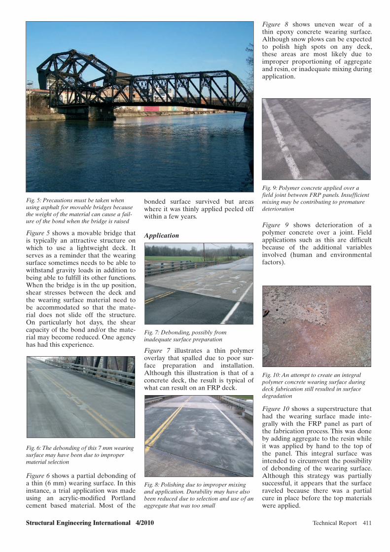
Structural Engineering International 4/2010 Technical Report 411
bonded surface survived but areas where it was thinly applied peeled off within a few years.
Application
Fig. 7: Debonding, possibly from inadequate surface preparation
Figure 7 illustrates a thin polymer overlay that spalled due to poor sur-face preparation and installation. Although this illustration is that of a concrete deck, the result is typical of what can result on an FRP deck.
Fig. 8: Polishing due to improper mixing and application. Durability may have also been reduced due to selection and use of an aggregate that was too small
Fig. 5: Precautions must be taken when using asphalt for movable bridges because the weight of the material can cause a fail-ure of the bond when the bridge is raised
Figure 5 shows a movable bridge that is typically an attractive structure on which to use a lightweight deck. It serves as a reminder that the wearing surface sometimes needs to be able to withstand gravity loads in addition to being able to fulfill its other functions. When the bridge is in the up position, shear stresses between the deck and the wearing surface material need to be accommodated so that the mate-rial does not slide off the structure. On particularly hot days, the shear capacity of the bond and/or the mate-rial may become reduced. One agency has had this experience.
Fig. 6: The debonding of this 7 mm wearing surface may have been due to improper material selection
Figure 6 shows a partial debonding of a thin (6 mm) wearing surface. In this instance, a trial application was made using an acrylic-modified Portland cement based material. Most of the
Figure 8 shows uneven wear of a thin epoxy concrete wearing surface. Although snow plows can be expected to polish high spots on any deck, these areas are most likely due to improper proportioning of aggregate and resin, or inadequate mixing during application.
Fig. 9: Polymer concrete applied over a field joint between FRP panels. Insufficient mixing may be contributing to premature deterioration
Figure 9 shows deterioration of a polymer concrete over a joint. Field applications such as this are difficult because of the additional variables involved (human and environmental factors).
Fig. 10: An attempt to create an integral polymer concrete wearing surface during deck fabrication still resulted in surface degradation
Figure 10 shows a superstructure that had the wearing surface made inte-grally with the FRP panel as part of the fabrication process. This was done by adding aggregate to the resin while it was applied by hand to the top of the panel. This integral surface was intended to circumvent the possibility of debonding of the wearing surface. Although this strategy was partially successful, it appears that the surface raveled because there was a partial cure in place before the top materials were applied.
x068.indd 411x068.indd 411 10/25/10 2:28 PM10/25/10 2:28 PM
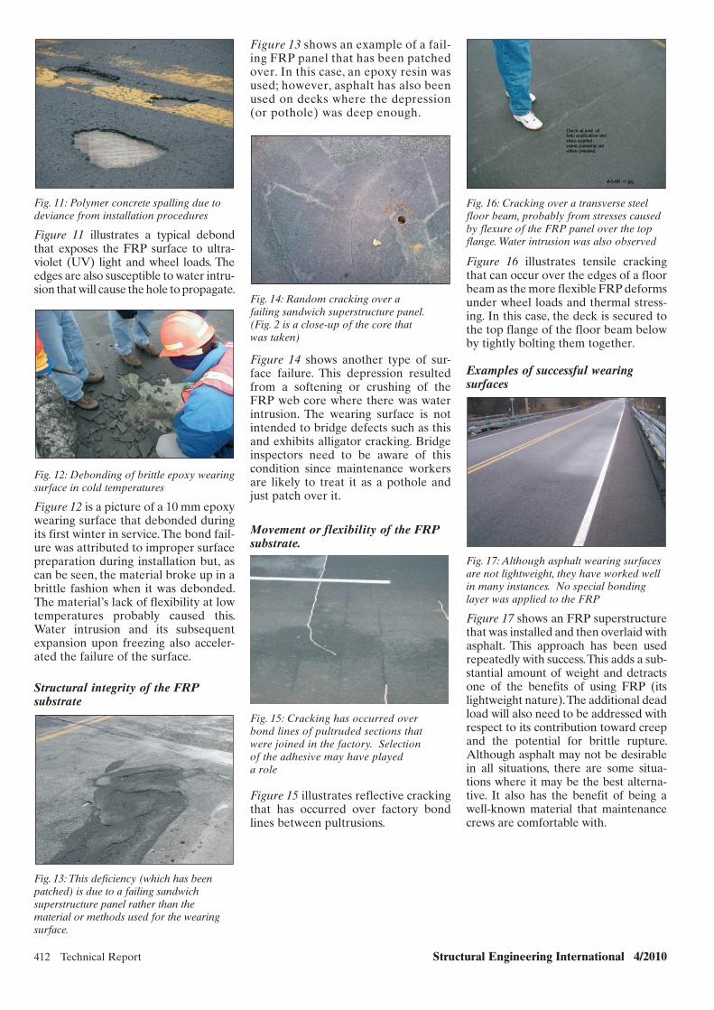
412 Technical Report Structural Engineering International 4/2010
Fig. 16: Cracking over a transverse steel floor beam, probably from stresses caused by flexure of the FRP panel over the top flange. Water intrusion was also observed
Figure 16 illustrates tensile cracking that can occur over the edges of a floor beam as the more flexible FRP deforms under wheel loads and thermal stress-ing. In this case, the deck is secured to the top flange of the floor beam below by tightly bolting them together.
Examples of successful wearing surfaces
Fig. 17: Although asphalt wearing surfaces are not lightweight, they have worked well in many instances. No special bonding layer was applied to the FRP
Figure 17 shows an FRP superstructure that was installed and then overlaid with asphalt. This approach has been used repeatedly with success. This adds a sub-stantial amount of weight and detracts one of the benefits of using FRP (its lightweight nature). The additional dead load will also need to be addressed with respect to its contribution toward creep and the potential for brittle rupture. Although asphalt may not be desirable in all situations, there are some situa-tions where it may be the best alterna-tive. It also has the benefit of being a well-known material that maintenance crews are comfortable with.
Figure 13 shows an example of a fail-ing FRP panel that has been patched over. In this case, an epoxy resin was used; however, asphalt has also been used on decks where the depression (or pothole) was deep enough.
Fig. 14: Random cracking over a failing sandwich superstructure panel.(Fig. 2 is a close-up of the core that was taken)
Figure 14 shows another type of sur-face failure. This depression resulted from a softening or crushing of the FRP web core where there was water intrusion. The wearing surface is not intended to bridge defects such as this and exhibits alligator cracking. Bridge inspectors need to be aware of this condition since maintenance workers are likely to treat it as a pothole and just patch over it.
Movement or flexibility of the FRP substrate.
Fig. 15: Cracking has occurred over bond lines of pultruded sections that were joined in the factory. Selection of the adhesive may have played a role
Figure 15 illustrates reflective cracking that has occurred over factory bond lines between pultrusions.
Fig. 11: Polymer concrete spalling due todeviance from installation procedures
Figure 11 illustrates a typical debond that exposes the FRP surface to ultra-violet (UV) light and wheel loads. The edges are also susceptible to water intru-sion that will cause the hole to propagate.
Fig. 12: Debonding of brittle epoxy wearing surface in cold temperatures
Figure 12 is a picture of a 10 mm epoxy wearing surface that debonded during its first winter in service. The bond fail-ure was attributed to improper surface preparation during installation but, as can be seen, the material broke up in a brittle fashion when it was debonded. The material’s lack of flexibility at low temperatures probably caused this. Water intrusion and its subsequent expansion upon freezing also acceler-ated the failure of the surface.
Structural integrity of the FRP substrate
Fig. 13: This deficiency (which has been patched) is due to a failing sandwich superstructure panel rather than the material or methods used for the wearing surface.
x068.indd 412x068.indd 412 10/25/10 2:28 PM10/25/10 2:28 PM

Structural Engineering International 4/2010 Technical Report 413
References
[1] Triandafilou L, O’Connor J. FRP Composites for Bridge Decks and Superstructures: State of the Practice in the U.S. Proceedings of Interna-tional Conference on Fiber Reinforced Polymer (FRP) Composites for Infrastructure Applications, University of the Pacific, Stockton, CA, 2009.
[2] Dutta P, Kwon S. Fatigue Performance Evaluation of FRP Composite Bridge Deck Prototypes Under High and Low Temperatures. 82nd Annual Meeting, Compendium of Papers on CD ROM, Transportation Research Board, Washington, D.C., 2003.
[3] Aboutaha R. Investigation of Durability of Wearing Surfaces for FRP Bridge Decks, Syracuse University, 2008.
[4] Wattanadechachan P, Aboutaha RS, Hag-Elsafi O, and Alampalli S. Thermal compatibility and durability of wearing surfaces on FRP bridge decks. ASCE Journal of Bridge Engineering 2006; 11(4), pp. 465-473; July–August.
[5] Barquist G, Lovejoy S, Nelson S, Soltesz S. Evaluation of Wearing Surface Materials for FRP Bridge Decks OR-DF-06-02, Oregon Department of Transportation, 2005.
specifically designed to insure a good bond and the upper course to provide the requisite durability and skid resis-tance.3 Reports of any such installa-tions are yet to be made available.
Conclusion
The vast majority of FRP deck and superstructure installations have per-formed well structurally, but success in the field has been diminished by the poor performance of several wearing surfaces, especially the ones made of thinly applied bonded materials that were used for weight saving. Better performance in the future can be obtained by proper selection of mate-rial, meticulous adherence to well-planned installation procedures, use of pull-off tests to check for proper sur-face preparation and bond, and use of a two-course system, where one is used to ensure bonding and a top layer is used for skid resistance and durability.
Fig. 18: Thin polymer concrete surfaces provide good skid resistance and protec-tion with little extra weight
Figure 18 illustrates a successful instal-lation of a polymer concrete overlay. After 5 years of service, this deck sur-face is still in “like-new” condition.
New York State and Oregon have undertaken research projects to explore some of the wearing surface issues presented above.3–5 The New York report by Aboutaha recommends applying the surface as two courses, one
x068.indd 413x068.indd 413 10/25/10 2:28 PM10/25/10 2:28 PM

414 Technical Report Structural Engineering International 4/2010
Examples of Applications of Fibre Reinforced Plastic Materials in Infrastructure in SpainAnurag Bansal, Research Engineer; John F. Monsalve Cano, Research Engineer; Bladimir O. Osorio Muñoz, Research
Engineer; Carlo Paulotto, Dr., Research Engineer; Acciona Infraestructuras, Alcobendas, Spain. Contact: [email protected]
Airport in the north of Spain [1]. This is a four-span bridge of total length of 46 m (see Fig. 1a). The bridge gird-ers are three continuous longitudinal carbon fibre beams on three inter-mediate supports connected to the reinforced concrete deck through alkali-resistant glass fibre shear con-nectors (see Fig. 1b). The beams are characterized by trapezoidal cross sections. They were manufactured in two parts and transported to the work site where they were joined by means of adhesive step joints. Each step joint was manufactured by placing the two parts of a beam side-by-side, wrapping them with pre-impregnated carbon fabric which was finally consolidated using the vacuum bag system. Using a crane, it took only half a day to place the three 46 m long beams on their supports. This was possible thanks to the minimal weight of the beams
at 1 kN/m. Glass fibre stay-in-place formworks were used to cast the con-crete deck. This bridge was the result of an international research project involving Spain, Colombia and Cuba, and it was aimed at demonstrating the possibility of building a road overpass using FRP materials.
The other two bridges are located on the outskirts of Madrid along the M-111 freeway [2]. These two bridges are identical, each made up of three simply supported spans (10, 14 and 10 m) with a 20,40 m wide box-girder deck (see Fig. 2a). The four hybrid carbon–glass fibre deck beams have reverse “Ω”-shaped cross sections (see Fig. 2b). Each beam was closed by connecting its top flange to a sandwich panel along its entire length. This panel initially acts both as the top flange of the beam and as formwork for the
Abstract
The introduction of new materials such as fibre reinforced plastics (FRPs) into construction practices has been discussed in this paper. Hereafter, some of the most significant examples of the applications of these new mate-rials are presented in some detail.
Keywords: carbon; glass; fibre; matrix; reinforcement.
Introduction
For the sake of clarity, the examples concerning the application of FRP materials in civil infrastructure in this paper are divided into two groups: structures and structural members entirely made with FRP materials and concrete structures or structural mem-bers, where FRP materials are used as external or internal reinforcement. The FRP beams employed to build up the girders of a road overpass along the A8 freeway close to the Asturias Airport in the north of Spain and those used for the girders of two bridges along the M-111 freeway in Madrid belong to the former group. To the same group belong two FRP slabs, used as a chan-nel bed during the channelling work of the Rio Mesoiro River in Galicia and the spiral stairs designed and manufac-tured for placement in a pumping well along one of the metro lines in Madrid. The FRP sheets used to reinforce both in shear and in bending a “reshaped” concrete beam in a building in Aragón and the FRP reinforcing bars used in some parts of the concrete substructure of the new tramway in Granada belong to the latter group.
Structures and Structural Members Made Entirely of FRP Materials
Asturias and M-111 Bridges
Since 2003, three vehicular bridges have been designed, manufactured and erected whose girder beams are completely made of FRP materi-als. The first bridge is located along the highway leading to the Asturias
(a) (b)
Fig. 1: (a) General view of the bridge in Asturias; (b) View of the carbon fibre beams and the glass fibre stay-in place formworks
(a) (b)
Fig. 2: (a) General view of one of the twin bridges along the M-111 freeway; (b) One of the FRP beams during positioning
x049.indd 414x049.indd 414 27/10/10 8:38 PM27/10/10 8:38 PM

Structural Engineering International 4/2010 Technical Report 415
using steel studs with one of their ends embedded in the FRP slabs.
Spiral Stairs for a Pumping Well in Madrid
The stairs of one of the pumping wells along one of the metro lines of Madrid were exposed to a highly aggressive environment owing to water and gasoline infiltrations. The well has a depth of 21,15 m and a
Fig. 3: Positioning of the FRP channel bed slabs
uncured concrete deck slab. Once the concrete has strengthened, the slab contributes to the deck strength, as it is connected to the top flanges of the beams through steel studs. The mini-mal weight of the beams (3 kN/m) meant that they could be placed on the supports using a simple crane truck. 12 beams were positioned during one working day. These two bridges were developed as demonstrators in the framework of a research project funded by the European Commission. The overall objective of the project was the development of a new high-performance and cost-effective con-struction concept for bridges based on the application of rapid-renewal and long-life service infrastructures in the countries that joined the European Union in 2004.
Rio Mesorio River Channelling
During the channelling work of the Rio Mesorio River in the Spanish region of Galicia, the channel had to cross a pre-existing oil pipeline at one point [3]. According to the origi-nal design, the channel consisted of a reinforced concrete hollow section composed of two identical cells. The section was 2,40 m high and 5,40 m wide, with all the walls having the same thickness of 0,30 m, except for the central vertical diaphragm that had a thickness of 0,50 m. During the excavation phase, it was found that the thickness of the soil layer covering the pipeline was less than expected. The level of the top face of the chan-nel’s bottom slabs however could not be varied, but executing the original plan would have meant interference between the bottom slabs and the oil pipes. To cope with this problem, the only feasible solution appeared to be reduction of the thickness of the slabs constituting the channel bed by replacing them with a material with better mechanical properties as com-pared with reinforced concrete. The use of steel was judged inappropriate due to possible corrosion problems. On the other hand, FRP materials, having both better mechanical proper-ties than reinforced concrete and not suffering from corrosion phenomena, appeared to be the best alternative. To optimize the cost of the FRP slabs, it was decided to manufacture them with a mix of carbon and glass fibre fabrics that were impregnated with epoxy resin to overcome the constraint imposed by the carbon fibre sizing. The slabs were manufactured by wet
lay-up and consolidated using the vacuum bag technique. The slabs were 2,50 m wide and 14,50 m long, and had a thickness of 0,05 m (see Fig. 3). They were manufactured in a workshop in Madrid and moved to the work site by truck. After the two FRP bottom slabs were put in place, the lateral walls and top slabs of reinforced concrete were cast (see Fig. 4). The structural connection between the FRP bottom slabs and the lateral walls was ensured
Fig. 4: View of the completed channel section
x049.indd 415x049.indd 415 27/10/10 8:38 PM27/10/10 8:38 PM
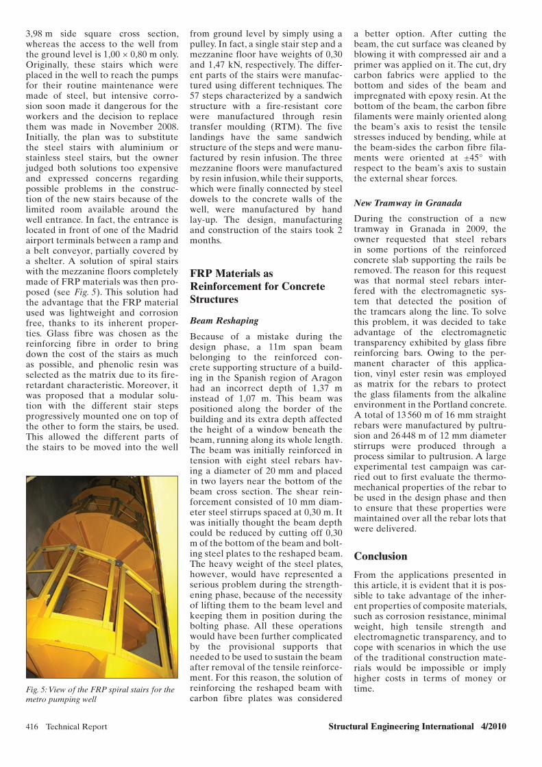
416 Technical Report Structural Engineering International 4/2010
3,98 m side square cross section, whereas the access to the well from the ground level is 1,00 × 0,80 m only. Originally, these stairs which were placed in the well to reach the pumps for their routine maintenance were made of steel, but intensive corro-sion soon made it dangerous for the workers and the decision to replace them was made in November 2008. Initially, the plan was to substitute the steel stairs with aluminium or stainless steel stairs, but the owner judged both solutions too expensive and expressed concerns regarding possible problems in the construc-tion of the new stairs because of the limited room available around the well entrance. In fact, the entrance is located in front of one of the Madrid airport terminals between a ramp and a belt conveyor, partially covered by a shelter. A solution of spiral stairs with the mezzanine floors completely made of FRP materials was then pro-posed (see Fig. 5). This solution had the advantage that the FRP material used was lightweight and corrosion free, thanks to its inherent proper-ties. Glass fibre was chosen as the reinforcing fibre in order to bring down the cost of the stairs as much as possible, and phenolic resin was selected as the matrix due to its fire-retardant characteristic. Moreover, it was proposed that a modular solu-tion with the different stair steps progressively mounted one on top of the other to form the stairs, be used. This allowed the different parts of the stairs to be moved into the well
Fig. 5: View of the FRP spiral stairs for the metro pumping well
from ground level by simply using a pulley. In fact, a single stair step and a mezzanine floor have weights of 0,30 and 1,47 kN, respectively. The differ-ent parts of the stairs were manufac-tured using different techniques. The 57 steps characterized by a sandwich structure with a fire- resistant core were manufactured through resin transfer moulding (RTM). The five landings have the same sandwich structure of the steps and were manu-factured by resin infusion. The three mezzanine floors were manufactured by resin infusion, while their supports, which were finally connected by steel dowels to the concrete walls of the well, were manufactured by hand lay-up. The design, manufacturing and construction of the stairs took 2 months.
FRP Materials as Reinforcement for Concrete Structures
Beam Reshaping
Because of a mistake during the design phase, a 11m span beam belonging to the reinforced con-crete supporting structure of a build-ing in the Spanish region of Aragon had an incorrect depth of 1,37 m instead of 1,07 m. This beam was positioned along the border of the building and its extra depth affected the height of a window beneath the beam, running along its whole length. The beam was initially reinforced in tension with eight steel rebars hav-ing a diameter of 20 mm and placed in two layers near the bottom of the beam cross section. The shear rein-forcement consisted of 10 mm diam-eter steel stirrups spaced at 0,30 m. It was initially thought the beam depth could be reduced by cutting off 0,30 m of the bottom of the beam and bolt-ing steel plates to the reshaped beam. The heavy weight of the steel plates, however, would have represented a serious problem during the strength-ening phase, because of the necessity of lifting them to the beam level and keeping them in position during the bolting phase. All these operations would have been further complicated by the provisional supports that needed to be used to sustain the beam after removal of the tensile reinforce-ment. For this reason, the solution of reinforcing the reshaped beam with carbon fibre plates was considered
a better option. After cutting the beam, the cut surface was cleaned by blowing it with compressed air and a primer was applied on it. The cut, dry carbon fabrics were applied to the bottom and sides of the beam and impregnated with epoxy resin. At the bottom of the beam, the carbon fibre filaments were mainly oriented along the beam’s axis to resist the tensile stresses induced by bending, while at the beam-sides the carbon fibre fila-ments were oriented at ±45° with respect to the beam’s axis to sustain the external shear forces.
New Tramway in Granada
During the construction of a new tramway in Granada in 2009, the owner requested that steel rebars in some portions of the reinforced concrete slab supporting the rails be removed. The reason for this request was that normal steel rebars inter-fered with the electromagnetic sys-tem that detected the position of the tramcars along the line. To solve this problem, it was decided to take advantage of the electromagnetic transparency exhibited by glass fibre reinforcing bars. Owing to the per-manent character of this applica-tion, vinyl ester resin was employed as matrix for the rebars to protect the glass filaments from the alkaline environment in the Portland concrete. A total of 13 560 m of 16 mm straight rebars were manufactured by pultru-sion and 26 448 m of 12 mm diameter stirrups were produced through a process similar to pultrusion. A large experimental test campaign was car-ried out to first evaluate the thermo-mechanical properties of the rebar to be used in the design phase and then to ensure that these properties were maintained over all the rebar lots that were delivered.
Conclusion
From the applications presented in this article, it is evident that it is pos-sible to take advantage of the inher-ent properties of composite materials, such as corrosion resistance, minimal weight, high tensile strength and electromagnetic transparency, and to cope with scenarios in which the use of the traditional construction mate-rials would be impossible or imply higher costs in terms of money or time.
x049.indd 416x049.indd 416 27/10/10 8:38 PM27/10/10 8:38 PM

Structural Engineering International 4/2010 Technical Report 417
References
[1] Gutierrez E, Primi S, Mieres JM, Calvo I. Structural testing of a vehicular carbon fiber bridge: quasi-static, and short-term behavior. J. Bridge Eng. ASCE 2008; 13 (3): 271–281.
[2] Primi S, Areiza M, Bansal A, Gonzalez A. New design and construction of a road bridge in composites materials in Spain: sustainability applied to civil works. In Proceedings of the 9th International Symposium On Fiber-Reinforced Polymer Reinforcement for Concrete Structures, 2009. Oehlers DJ, Griffith MC, Seracino R (eds). Sydney, New South Wales, 2009, 62. ISBN: 9780980675504.
[3] Paulotto C, Primi S, Bansal A. A composite bed for the Rio Mesorio river. Proceedings of the Composites UK 10th Annual Conference, Birmingham, England, 2010.
SEI Data BlockEI Data Block
Owner: Ministerio de Fomento (for the Asturias bridge); Comunidad de Madrid (for the M111 bridges)
Designer:Acciona Infraestructuras (for all the 3 bridges)
Main contractor:Acciona Infraestructuras (for all the 3 bridges)
FRP fabricator:Acciona Infraestructuras (for all the 3 bridges)
FRP (t): 15 (for the Asturias bridge); 22,5 (for each one the M111 bridges)Span lengths (m): 46 (for the Asturias bridge); 34 (for each one of the M111 bridges)
Construction cost (USD million): 0,5 (for the Asturias bridge); 0,5 (for each one of the M111 bridges)
Service date: 2004 (for the Asturias bridge); 2008 (for both the M111 bridges)
www.iabse.org/SEI
2 Print Copies per issue (Feb, May, Aug., Nov)
Online Access to the Journal for the entire
Institution via Site License
Online Access to Current + Back issues (1991- )
at no extra cost (1500 and more SEI articles)
only CHF 630 a year.
Sign up for an Institutional Subscription
x049.indd 417x049.indd 417 27/10/10 8:38 PM27/10/10 8:38 PM
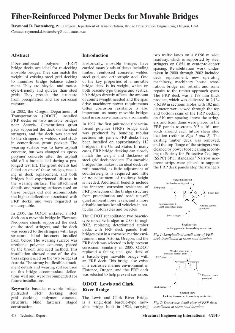
418 Technical Report Structural Engineering International 4/2010
Fiber-Reinforced Polymer Decks for Movable BridgesRaymond D. Bottenberg, P.E., Oregon Department of Transportation, Bridge Preservation Engineering, Oregon, USA.
Contact: [email protected]
Introduction
Historically, movable bridges have carried many kinds of decks including timber, reinforced concrete, welded steel grid, and orthotropic steel. One of the key properties of a movable bridge deck is its weight, which on both bascule-type bridges and vertical lift bridges directly affects the amount of counterweight needed and the span drive machinery power requirements. Often corrosion resistance is also important, as many movable bridges exist in corrosive marine environments.
In 1997, the first pultruded fiber-rein-forced polymer (FRP) bridge deck was produced by bonding tubular sections into panels. FRP decks have been installed on approximately 112 bridges in the United States. In many cases, FRP bridge decking can closely match the weight and thickness of steel grid deck products. For movable bridges, this makes it an ideal deck ret-rofit material, as little adjustment of counterweights is required and little or no adjustment of roadway height is needed. Additional benefits include the inherent corrosion resistance of FRP, protection of the bridge structure from precipitation and road run-off, quiet ambient noise levels, and a more drivable surface for all vehicles, in par-ticular motorcycles and bicycles.
The ODOT rehabilitated two bascule-type movable bridges in 2000 through 2002, replacing deteriorated timber decks with FRP deck panels. Both bridges exist in a corrosive marine envi-ronment near Astoria, Oregon, and the FRP deck was selected to help prevent corrosion. Similarly in 2005, ODOT replaced a failing steel grid deck of a bascule-type movable bridge with an FRP deck. This bridge also exists in a corrosive marine environment in Florence, Oregon, and the FRP deck was selected to help prevent corrosion.
ODOT Lewis and Clark River Bridge
The Lewis and Clark River Bridge is a single-leaf bascule-type mov-able bridge built in 1924, carrying
two traffic lanes on a 6,096 m wide roadway, which is supported by steel stringers on 0,851 m center-to-center spacing. Rehabilitation work under-taken in 2000 through 2002 included deck replacement, new operating machinery, machinery house resto-ration, bridge rail retrofit and some repairs to the timber approach spans. The FRP deck was a 178 mm thick product, which was delivered in 2,134 × 6,199 m sections. Holes with 102 mm diameter were sawed through the top and bottom skins of the FRP decking on 610 mm spacing above the string-ers, and foam dams were placed in the FRP panels to create 203 × 161 mm voids around each future shear stud location (refer to Figs. 1 and 2). The existing timber deck was removed, and the top flange of the stringers was cleaned by power tool cleaning accord-ing to Society for Protective Coatings (SSPC) SP11 standards.1 Narrow neo-prene strips were placed to support the FRP deck panels atop the stringers
Abstract
Fiber-reinforced polymer (FRP) bridge decks are ideal for re-decking movable bridges. They can match the weight of existing steel grid decking to minimize bridge balance adjust-ment. They are bicycle- and motor-cycle-friendly and quieter than steel grids. They protect the structure from precipitation and are corrosion resistant.
In 2002, the Oregon Department of Transportation (ODOT) installed FRP decks on two movable bridges near Astoria. Cementitious grout pads supported the deck on the steel stringers, and the deck was secured to the stringers by welded steel studs in cementitious grout pockets. The wearing surface was to have asphalt concrete, but was changed to epoxy polymer concrete after the asphalt slid off a bascule leaf during a pro-longed test lift. The grout details had failed on one of these bridges, result-ing in deck replacement, and both bridges had experienced distress in the wearing surface. The attachment details and wearing surfaces used on these bridges did not accommodate the higher deflections associated with FRP decks, and were regarded as unacceptable.
In 2005, the ODOT installed a FRP deck on a movable bridge in Florence. Neoprene sheets supported the deck on the steel stringers, and the deck was secured to the stringers with large structural blind fasteners installed from below. The wearing surface was urethane polymer concrete, placed by the broom and seed method. This installation showed none of the dis-tress experienced on the two bridges at Astoria. The strong but flexible attach-ment details and wearing surface used on this bridge accommodate deflec-tions well and were recommended for future installations.
Keywords: bascule; movable bridge; pultruded FRP decking; steel grid decking; polymer concrete; structural blind fastener; staged construction.
Welded shear studPortland cement grout
FRP panel
Neoprene strip &Light gauge steel angle
Steel stringer
Section viewlooking parallel to roadway centerline
Portland cementgrout pad
Foam dam
Fig. 1: Longitudinal detail view of FRP deck installation at shear stud location
Welded shear studPortland cement grout
FRP panel
Portland cementgrout pad
Section viewlooking transverse to roadway centerline
Steel stringer
Fig. 2: Transverse detail view of FRP deck installation at shear stud location
x055.indd 418x055.indd 418 27/10/10 7:12 PM27/10/10 7:12 PM
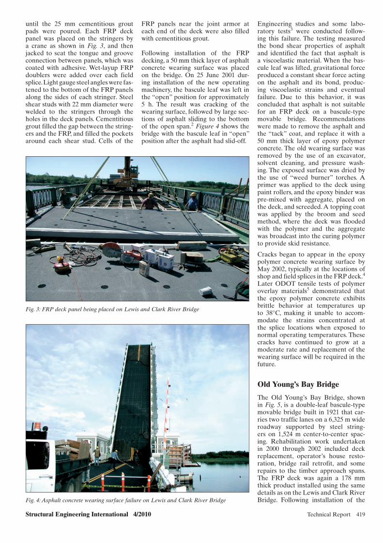
Structural Engineering International 4/2010 Technical Report 419
until the 25 mm cementitious grout pads were poured. Each FRP deck panel was placed on the stringers by a crane as shown in Fig. 3, and then jacked to seat the tongue and groove connection between panels, which was coated with adhesive. Wet-layup FRP doublers were added over each field splice. Light gauge steel angles were fas-tened to the bottom of the FRP panels along the sides of each stringer. Steel shear studs with 22 mm diameter were welded to the stringers through the holes in the deck panels. Cementitious grout filled the gap between the string-ers and the FRP, and filled the pockets around each shear stud. Cells of the
FRP panels near the joint armor at each end of the deck were also filled with cementitious grout.
Following installation of the FRP decking, a 50 mm thick layer of asphalt concrete wearing surface was placed on the bridge. On 25 June 2001 dur-ing installation of the new operating machinery, the bascule leaf was left in the “open” position for approximately 5 h. The result was cracking of the wearing surface, followed by large sec-tions of asphalt sliding to the bottom of the open span.2 Figure 4 shows the bridge with the bascule leaf in “open” position after the asphalt had slid-off.
Engineering studies and some labo-ratory tests3 were conducted follow-ing this failure. The testing measured the bond shear properties of asphalt and identified the fact that asphalt is a viscoelastic material. When the bas-cule leaf was lifted, gravitational force produced a constant shear force acting on the asphalt and its bond, produc-ing viscoelastic strains and eventual failure. Due to this behavior, it was concluded that asphalt is not suitable for an FRP deck on a bascule-type movable bridge. Recommendations were made to remove the asphalt and the “tack” coat, and replace it with a 50 mm thick layer of epoxy polymer concrete. The old wearing surface was removed by the use of an excavator, solvent cleaning, and pressure wash-ing. The exposed surface was dried by the use of “weed burner” torches. A primer was applied to the deck using paint rollers, and the epoxy binder was pre-mixed with aggregate, placed on the deck, and screeded. A topping coat was applied by the broom and seed method, where the deck was flooded with the polymer and the aggregate was broadcast into the curing polymer to provide skid resistance.
Cracks began to appear in the epoxy polymer concrete wearing surface by May 2002, typically at the locations of shop and field splices in the FRP deck.4 Later ODOT tensile tests of polymer overlay materials5 demonstrated that the epoxy polymer concrete exhibits brittle behavior at temperatures up to 38°C, making it unable to accom-modate the strains concentrated at the splice locations when exposed to normal operating temperatures. These cracks have continued to grow at a moderate rate and replacement of the wearing surface will be required in the future.
Old Young’s Bay Bridge
The Old Young’s Bay Bridge, shown in Fig. 5, is a double-leaf bascule-type movable bridge built in 1921 that car-ries two traffic lanes on a 6,325 m wide roadway supported by steel string-ers on 1,524 m center-to-center spac-ing. Rehabilitation work undertaken in 2000 through 2002 included deck replacement, operator’s house resto-ration, bridge rail retrofit, and some repairs to the timber approach spans. The FRP deck was again a 178 mm thick product installed using the same details as on the Lewis and Clark River Bridge. Following installation of the
Fig. 3: FRP deck panel being placed on Lewis and Clark River Bridge
Fig. 4: Asphalt concrete wearing surface failure on Lewis and Clark River Bridge
x055.indd 419x055.indd 419 27/10/10 7:12 PM27/10/10 7:12 PM

420 Technical Report Structural Engineering International 4/2010
Siuslaw River Bridge
The Siuslaw River Bridge is a double-leaf bascule-type movable bridge built in 1936, carrying two traffic lanes on an 8,230 m wide roadway, which is supported by steel stringers on 0,914 m center-to-center spacing. Retrofit work undertaken in 2005 included deck replacement, recycled plastic lumber sidewalk decking, and new reinforced plastic walers on the fender system. The steel grid deck had been support-ing the sidewalks, and the FRP deck retrofit required installation of new supports made from rectangular steel tubing, spanning between sidewalk brackets to keep the loads off the FRP decking. Stringer splices were modified by moving the splice plates to the bot-tom of the stringer flange and install-ing with countersunk fasteners. The FRP deck was a 127 mm thick product which was delivered in 2,438 × 4,089 m sections. The existing steel grid deck was removed, and the top flange of the stringers was repaired and cleaned by needle guns to SSPC SP11 standards.1 Neoprene pads with 3 mm thickness were placed on each stringer. Each FRP deck panel was placed on the stringers by a crane, and then jacked to seat the tongue and groove connection between panels, which was coated with adhesive. Wet-layup FRP doublers were added over each field splice. The FRP deck panels were secured with 16 mm diameter structural blind fasteners through existing holes in the stringer flanges and newly drilled matching holes in the FRP. This installation is shown in Fig. 8. Cells of the FRP pan-els near the joint armor at each end of each deck were filled with urethane.
The deck was installed in two stages to meet traffic needs, with the FRP panels spliced at roadway centerline. The bottom skins of the FRP panels were fastened securely to the flange of a stringer located at the center-line. The top skins of the FRP panels were fastened together using a 2,7 mm thick 304 stainless steel plates, abrasive blasted and installed using a polyurethane adhesive sealant and 6,4 mm diameter stainless steel structural blind fasteners.
Owing to the problems with the poly-mer concrete wearing surfaces on the Astoria bridges, further laboratory tension testing5 was performed with a variety of polymer concrete wear-ing surface materials cast into dog-bone-shaped specimens. This testing revealed that the epoxy polymer
grout between the FRP panels and the stringers also failed, starting at the joint armor and propagating along the stringers. Due to these failures and consequent FRP panel damage, this deck was replaced in June 2010 with a steel grid deck at the request of ODOT district management. These failures could have been avoided by using ductile materials for the wearing surface and using strong but flexible materials for the attachment details to accommodate the deformations experienced between the flexible steel floor system and the more flexible FRP deck panels.
FRP decking, a 19 mm thick epoxy polymer concrete wearing surface was placed by the broom and seed method.
Cracks began to appear on the epoxy polymer concrete wearing surface by May 2002 similar to the crack-ing observed on the Lewis and Clark River Bridge. These cracks continued growing at an aggressive rate,4 prob-ably exacerbated by increased deflec-tions due to defective shop splices. An advanced example of this cracking is shown in Fig. 6. The cementitious grout around the shear studs failed as shown in Fig. 7. The cementitious
Fig. 5: Historic view of Old Young’s Bay Bridge in the “open” position
Fig. 6: Cracking and spalling of epoxy polymer concrete wearing surface on the Old Young’s Bay Bridge
x055.indd 420x055.indd 420 27/10/10 7:12 PM27/10/10 7:12 PM
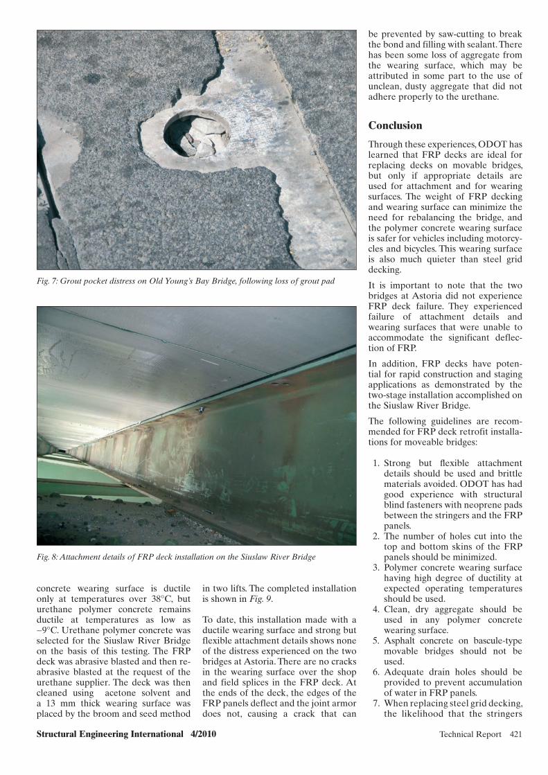
Structural Engineering International 4/2010 Technical Report 421
Fig. 7: Grout pocket distress on Old Young’s Bay Bridge, following loss of grout pad
Fig. 8: Attachment details of FRP deck installation on the Siuslaw River Bridge
be prevented by saw-cutting to break the bond and filling with sealant. There has been some loss of aggregate from the wearing surface, which may be attributed in some part to the use of unclean, dusty aggregate that did not adhere properly to the urethane.
Conclusion
Through these experiences, ODOT has learned that FRP decks are ideal for replacing decks on movable bridges, but only if appropriate details are used for attachment and for wearing surfaces. The weight of FRP decking and wearing surface can minimize the need for rebalancing the bridge, and the polymer concrete wearing surface is safer for vehicles including motorcy-cles and bicycles. This wearing surface is also much quieter than steel grid decking.
It is important to note that the two bridges at Astoria did not experience FRP deck failure. They experienced failure of attachment details and wearing surfaces that were unable to accommodate the significant deflec-tion of FRP.
In addition, FRP decks have poten-tial for rapid construction and staging applications as demonstrated by the two-stage installation accomplished on the Siuslaw River Bridge.
The following guidelines are recom-mended for FRP deck retrofit installa-tions for moveable bridges:
1. Strong but fl exible attachment details should be used and brittle materials avoided. ODOT has had good experience with structural blind fasteners with neoprene pads between the stringers and the FRP panels.
2. The number of holes cut into the top and bottom skins of the FRP panels should be minimized.
3. Polymer concrete wearing surface having high degree of ductility at expected operating temperatures should be used.
4. Clean, dry aggregate should be used in any polymer concrete wearing surface.
5. Asphalt concrete on bascule-type movable bridges should not be used.
6. Adequate drain holes should be provided to prevent accumulation of water in FRP panels.
7. When replacing steel grid decking, the likelihood that the stringers
concrete wearing surface is ductile only at temperatures over 38°C, but urethane polymer concrete remains ductile at temperatures as low as −9°C. Urethane polymer concrete was selected for the Siuslaw River Bridge on the basis of this testing. The FRP deck was abrasive blasted and then re-abrasive blasted at the request of the urethane supplier. The deck was then cleaned using acetone solvent and a 13 mm thick wearing surface was placed by the broom and seed method
in two lifts. The completed installation is shown in Fig. 9.
To date, this installation made with a ductile wearing surface and strong but flexible attachment details shows none of the distress experienced on the two bridges at Astoria. There are no cracks in the wearing surface over the shop and field splices in the FRP deck. At the ends of the deck, the edges of the FRP panels deflect and the joint armor does not, causing a crack that can
x055.indd 421x055.indd 421 27/10/10 7:12 PM27/10/10 7:12 PM

422 Technical Report Structural Engineering International 4/2010
quality control programs should be specifi ed.
10. A saw-cut and fl exible sealant between the FRP deck panels and rigid joint armor should be provided.
References
[1] Surface Preparation Standard No. 11, Power Tool Cleaning to Bare Metal. SSPC: The Society for Protective Coatings. Pittsburgh, PA, September 1, 2000 and November 1, 2004 revisions.
[2] Nelson J. Asphalt Crashes Down From Bridge. The Oregonian. Portland, Oregon, June 27, 2001.
[3] Lovejoy SC, Nelson SD, Patterson BM. Causes and Solutions to the Failure of the Wear Surface on the Lewis and Clark River Bridge. Unpublished report. Oregon Department of Transportation, November 21, 2001.
[4] Lovejoy SC. Summary of Cracking in the Wearing Surface of the FRP Decks on Bridges 0711 (Lewis and Clark River) and 0330 (Old Young’s Bay). Unpublished report. Oregon Department of Transportation, October 20, 2004.
[5] Barquist G, Lovejoy SC, Nelson SD, Soltesz S. Evaluation of Wearing Surface Materials for FRP Bridge Decks. Oregon Department of Transportation and Federal Highway Administration, July, 2005.
Fig. 9: View of completed FRP deck installation on the Siuslaw River Bridge
will have wear damage and may require replacement should be considered.
8. Stringer splices with plates on top of the top fl ange should be modi-
fi ed to a confi guration with coun-tersunk fasteners and splice plates on the underside of the top fl ange.
9. FRP deck products made by manu facturers that have effective
Contact: [email protected], Subject: Subscription Gift
Make Your Client Remember Youthrough out the Year..
Gift a SEI SubscriptionCHF 220/Year for 4 issues.
x055.indd 422x055.indd 422 27/10/10 7:13 PM27/10/10 7:13 PM

Structural Engineering International 4/2010 Technical Report 423
Glass Fiber Reinforced Polymer Strengthening and Evaluation of Railroad Bridge MembersGangaRao V.S. Hota, Prof., Ph.D., P.E., Director; P.V. Vijay, Research Prof., PhD, PE; Dept. of Civil and Environmental
Engineering West Virginia University, Morgantown, USA and Reza S. Abhari, MSCE, PE, Structural Eng., Alpha Corporation; USA.
Contact: [email protected]
wood for bridge construction. The US railroads have more than 2400 km of timber bridges and trestles in service today, which typically provide more than 50 years of acceptable service when properly designed, constructed, and maintained.1 With the recent increases in railway car axle loads and long-term exposure to the envi-ronment, many of these bridges have reached the end of their service life or their load carrying capacity has low-ered significantly because of material aging. This work describes the use of GFRP for rehabilitating in-service superstructure and substructure rail-road timber bridge members.
Objectives and Scope
The work presented herein focuses on developing safer, faster, and most prac-tical methods that allow in situ reha-bilitation of timber railroad bridges without interrupting rail traffic. The objective of this research work is to evaluate the application of GFRP composite spray and wraps as a viable rehabilitation alternative for string-ers and piles on in-service timber bridges. In this work, damaged tim-ber bridge stringers and piles selected by the South Branch Valley Railroad (SBVR) in Moorefield, WV, USA were repaired and rehabilitated with the use of GFRP composites. The work con-sisted of: (a) determining bending and shear properties of damaged timber stringers removed from field-service, and performing analytical compari-sons prior to and after repair through sprayed GFRP (SGFRP) and vacuum bagging methods, and (b) rehabilitat-
ing and evaluating timber railroad bridge piles under static and dynamic loads (up to 24 km/h).
Stringer Rehabilitation Scheme
A total of four 50+ year-old creosote-treated Douglas-fir stringers were acquired from the SBVR-WVDOT. The four stringers were deemed defi-cient due to significant checking and splitting along their length (Fig. 1). All four specimens (152 × 203 × 3560 mm) were load tested up to 26,7 kN before repair to determine flexural rigidity and shear modulus. Stringers were sur-face prepared by removing dirt and debris, by filling of void or splits with fillers (resin and saw dust mix), and edge smoothening to reduce stress concentrations. After sanding, primer coat (phenolic resin) was applied and cured. Retrofitting was done using the most compatible primer/resin combi-nation using phenolic formaldehyde.
Vacuum Bagging and GFRP Spray Methods
Vacuum bagging creates clamping forces (127–152 mm Hg vacuum) to hold the resin-coated fiber/fabric components in place and removes the trapped air. Fabric pieces were cut to cover three sides of the specimen. The vacuum bagging method used a sealed plastic bag covering the lay-up area including a breather layer, and a vacuum pump to remove the air and apply uniform surface pressure during resin curing (Fig. 1). For the SGFRP method, two separate compressed air spray guns were used, in lieu of an
Abstract
In this work, damaged timber rail-road bridge stringers and piles were rehabilitated with glass fiber rein-forced polymer (GFRP) composites, and tested. Four timber stringers (152 × 203 × 3560 mm) removed from the field were rehabilitated with GFRP spray lay-up and GFRP wrap vacuum bagging methods. GFRP strength-ening increased the shear moduli of the two stringers by 41 and 267%. Rehabilitation and load testing were also performed on an open-deck-tim-ber railroad bridge built during the early 1900s on the South Branch Valley Railroad (SBVR) owned by the West Virginia Department of Transporta-tion (WVDOT) in Moorefield, WV, USA. Specifically, field rehabilitation involved repairing piles using GFRP composite wraps and phenolic formal-dehyde adhesives. Static and dynamic tests using a 80 ton locomotive showed that the rehabilitated piles and pile cap showed a 43 and 46% strain reduction, respectively. Dynamic load amplifi-cation factor was noted to be almost close to a speed of 24 km/h.
Keywords: strengthening; GFRP; com-posites; rehabilitation; timber piles; timber stringers.
Introduction
In the USA, timber was the primary railroad bridge construction material until the early 20th century. The use of lumber began to slowly decline in the early 20th century as other materi-als such as steel and concrete replaced
Vacuum bagcovering the
wrapped area Vacuum pump
(a) (b) (c)
Fig. 1: Rehabilitation of timber stringers: (a) field-removed stringers; (b) vacuum bagging of wrapped beam; (c) spraying fiber on the wet surface
x057.indd 423x057.indd 423 25/10/10 5:46 PM25/10/10 5:46 PM
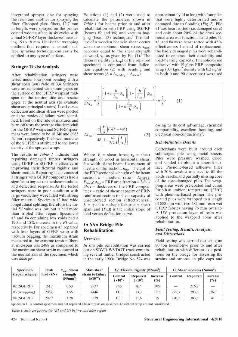
424 Technical Report Structural Engineering International 4/2010
Equations (1) and (2) were used to calculate the parameters shown in Table 1 for beams prior to and after rehabilitation with FRP using SGFRP (beams #2 and #4) and vacuum bag-ging (beam #3) techniques.2 The fail-ure of a wooden beam in shear occurs when the maximum shear stress, smax, becomes equal to the shear strength of wood, sd, as given by Eq. (1).2 The flexural rigidity (EIexp) of the repaired specimens is computed from deflec-tion equation (2) with bending and shear terms (Δ = Δbending + Δshear).
integrated sprayer, one for spraying the resin and another for spraying the fiber. Chopped glass fibers, 12,7 mm in length, were sprayed on the primer coated wood surface in six cycles with a final SGFRP layer thickness measur-ing 15 to 18 mm. Unlike the wrapping method that requires a smooth sur-face, spraying technique can easily be applied to any type of surface.
Stringer Tests/Analysis
After rehabilitation, stringers were tested under four-point bending with a shear span (a/h) ratio of 3,4. Stringers were instrumented with strain gages on the surface of the GFRP wraps at mid-span on the tension side and rosette gages at the neutral axis (to evaluate shear and principal strains). Load versus deflection and shear strain were plotted and the modes of failure were identi-fied. Based on the rule of mixtures and burn-off tests, the average elastic moduli for the GFRP wraps and SGFRP speci-mens were found to be 18 340 and 8963 N/mm2, respectively. The lower modulus of the SGFRP is attributed to the lower density of the sprayed wraps.
The results in Table 1 indicate that repairing damaged timber stringers using GFRP or SGFRP is effective in improving their flexural rigidity and shear moduli. Repairing shear zones of a stringer with GFRP composites had a significant impact on the shear modulus and deflection response. As the tested stringers were in poor condition with large voids, they were filled with strong filler material. Specimen #2 had wide longitudinal splitting, therefore the ini-tial EI value was low, but it had more than tripled after repair. Specimens #3 and #4 containing less voids had a 19,5 and 15% increase in the EI value, respectively. For specimen #3 repaired with four layers of GFRP wrap with vacuum bagging, the maximum strain measured at the extreme tension fibers at mid-span was 2488 µε compared to the maximum shear strain measured at the neutral axis of the specimen, which was 4446 µε.
Specimen/(repair scheme)
Peak load (kN)
s max, Shear strength (N/mm2)
Max. shear strain to failure
(×10−6)
EI, Flexural rigidity (N/mm2) G, Shear modulus (N/mm2)
Control (×106)
Repaired (×106)
Increase (%)
Control Repaired Increase (%)
#2 (SGFRP) 161,5 0,53 2937 2,85 8,7 305 — 216,2 —
#3 (wrapping) 206,6 1,55 4446 11,1 13,3 19,5 295,3 793,6 267
#4 (SGFRP) 209,3 1,28 3379 10,1 11,6 15 270,7 383,6 41
Specimen #1 is control specimen and not repaired. Shear strains on specimen #2 without wrap are not considered.
Table 1: Stringer properties (EI and G) before and after repair
EIa
PL a
aGA
Pexp
( – )
–=
3 4
48 12
2 2
(2)
Where V = shear force; sd = shear strength of wood in horizontal shear; b = width of the beam; I = moment of inertia of the section; hfrp = height of the FRP section; h = height of the beam section; n = modular ratio = ESGFRP/Ewood; r frp = FRP area fraction = 2thfrp/bh; t = thickness of the FRP compos-ite; r = ratio of shear capacity of FRP-reinforced section to shear capacity of unreinforced section (effectiveness); L = span; k = shape factor; a = shear span; and (P/D) is the initial slope of load versus deflection curve.
In Situ Bridge Pile Rehabilitation
Overview
In situ pile rehabilitation was carried out on SBVR-WVDOT track contain-ing several timber bridges constructed in the early 1900s. Bridge No. 574 was
vbh
nh
hh
h
d
=
+ +23
1 1
2
frpfrp
frpfrpp
frpfrp+1 n
h
h
= 23
r (1)
approximately 14 m long with four piles that were highly deteriorated and/or damaged due to flooding (Fig. 2). Pile #1 was heart rotted (i.e. damaged core) and only about 20% of the cross sec-tional area was functional, and piles #2, #3, and #4 were heart rotted with 45% effectiveness. Instead of replacement, the badly damaged piles were rehabili-tated to enhance their durability and load-bearing capacity. Phenolic-based adhesive with E-glass FRP composite wrap (0,4 kg/m2 density with 0,2 kg/m2 in both 0 and 90 directions) was used
owing to its cost advantage, chemical compatibility, excellent bonding, and electrical non-conductivity3.
Rehabilitation Details
Cofferdams were built around each submerged pile using metal sheets. Piles were pressure washed, dried, and sanded to obtain a smooth sur-face. Phenolic-based adhesive filler with 20% sawdust was used to fill the voids, cracks, and partially missing core of the core-damaged piles. The wrap-ping areas were pre-coated and cured for 6 h at ambient temperature (27°C) with phenolic-based primer. The pre-coated piles were wrapped to a length of 888 mm with two 482 mm resin wet GFRP fabrics having 76 mm overlap. A UV protection layer of resin was applied to the wrapped areas after rehabilitation.
Field Testing, Results, Analysis, and Discussions
Field testing was carried out using an 80 ton locomotive prior to and after rehabilitation with different axle posi-tions on the bridge for assessing the strains and stresses in pile caps and
x057.indd 424x057.indd 424 25/10/10 5:47 PM25/10/10 5:47 PM

Structural Engineering International 4/2010 Technical Report 425
Loading Pile 4
Pile 3
Pile 2
Pile 1
Pile Cap
Micro-strains
Center of rear axle on pile bent
Before rehabilitation — −243 −144 152 230
After rehabilitation −185 −138 −127 108 129
Reduction (%) 43 12 29 44
24 km/h Before rehabilitation — −364 −150 278 253
After rehabilitation −376 −229 −134 119 146
Reduction (%) 37 11 57 42
Negative (−) strain–compression; positive (+) strain–tension.
Table 2: Results for different load cases before and after rehabilitation
1219 1524 All dimensionsin mm
Averagewaterlevel
305610Pile 2
1676
Pile 3
1067
Wrappedheight888 mm
1981
Pile 4 Pile 1
Straingage
36584571575508
D = 305 D = 610 D = 610 D = 305
(a) (b) (c)
Fig. 2: Pile rehabilitation: (a) water submerged piles; (b) pile repaired with GFRP; (c) pile configuration and strain gage locations
Pile 1: before rehabAfter rehab
Pile 2: before rehabAfter rehab
Pile 3: before rehabAfter rehab
−400
−300
−200
−100
Mic
ro s
trai
ns
010 11 12 13 14 15
100
200
300
(a) (b)
Fig. 3: Dynamic load testing: (a) 80 ton locomotive; (b) time versus strain data for piles at 24 km/h
piles. The piles were not symmetri-cally placed when the bridge was built and this can be seen from the dimen-sions in Fig. 2. After rehabilitation, the strains induced in the timber piles and pile caps under different load condi-tions were reduced up to 43 and 46%, respectively (Table 2), with improved load distribution. Pile #2 was not reha-bilitated and was considered as a con-trol pile. It was also noted that strain values for pile #1 were in tension, instead of being in compression, which
is attributed to local stress patterns and pile buckling at the top section and the displacement of the whole pile from its original axis. Dynamic load testing up to the SBVR-DOT recommended maximum speed on the bridge showed that the strains were similar to static values with a dynamic load amplifica-tion (impact) factor of 1 up to a speed of 24 km/h (Fig. 3). Dynamic load test-ing also showed a strain reduction in the FRP rehabilitated piles #1 and #3, and showed no change in the strain
value of control pile #2, which was not rehabilitated (Fig. 3).
Conclusion
Damaged stringers strengthened with GFRP and tested under controlled laboratory conditions showed a 267 and 41% improvement in the shear modulus when repaired with wrapping method and SGFRP method, respec-tively. The 50+ year-old in situ rehabili-tated timber railroad bridge subjected to static and dynamic loads using an 80 ton locomotive, revealed a reduction in pile cap strains by approximately 44% and in the piles by approximately 57%. The dynamic effect was negligi-ble at the speed ranges up to 24 km/h in most of the piles. GFRP composite fabric in combination with phenolic formaldehyde adhesives was found to perform well with excellent bonding under harsh environments for GFRP wrapped timber piles.
Acknowledgement
Funding provided by Federal Railroad Authority (FRA) and West Virginia
x057.indd 425x057.indd 425 25/10/10 5:47 PM25/10/10 5:47 PM
426 Technical Report Structural Engineering International 4/2010
Division of Highways (WVDOH), USA for this work is acknowledged.
References
[1] Ritter M. Timber Bridges. Construction, Inspection and Maintenance. United States Department of Agriculture Forest Service, 1990.
[2] Triantafillou T. Shear reinforcement of wood using FRP materials. J. Mater. Civil Eng. ASCE, 9(2), 1997.
[3] Abhari RS. Rehabilitation of Timber Railroad Bridges using GFRP Composites, MS Thesis, West Virginia University, 2007.
SEI Data BlockEI Data Block
Owner:South Branch Valley Railroad, Authority, West Virgin ia (WV) Department of Transportation (USA)
Designer:Constructed Facilities Center, West Virginia University, Morgantown, WV.
Main contractor:Constructed Facilities Center, West Virginia University, Morgantown, WV.
FRP fabricator:Constructed Facilities Center, West Virginia University, Morgantown, WV.
FRP (t): 0, 1 Span lengths (m): 3560 mm (stringers) and 14000 mm (bridges)
Rehabilitation cost (USD million): Less than 10,000
Service date: 2001/2004 (Different times of rehabilitation)
x084.indd 349 7/21/10 1:13:05 PMx057.indd 426x057.indd 426 25/10/10 5:47 PM25/10/10 5:47 PM
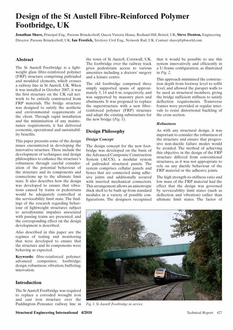
Structural Engineering International 4/2010 Technical Report 427
Design of the St Austell Fibre-Reinforced Polymer Footbridge, UKJonathan Shave, Principal Eng., Parsons Brinckerhoff, Queen Victoria House, Redland Hill, Bristol, UK; Steve Denton, Engineering
Director, Parsons Brinckerhoff, UK; Ian Frostick, Territory Civil Eng., Network Rail, UK. Contact: [email protected]
the town of St Austell, Cornwall, UK. The footbridge over the railway track gives pedestrians access to various amenities including a doctors’ surgery and a leisure centre.
The old footbridge comprised three simply supported spans of approxi-mately 5, 14 and 6 m, respectively, and was supported by masonry piers and abutments. It was proposed to replace the superstructure with a new fibre-reinforced polymer (FRP) structure and adapt the existing substructure for the new bridge (Fig. 1).
Design Philosophy
Design Concept
The design concept for the new foot-bridge was developed on the basis of the Advanced Composite Construction System (ACCS), a modular system of pultruded structural panels. The system comprises cellular panels and boxes that are connected using adhe-sive joints and additionally secured with inserted mechanical connectors. This arrangement allows an anisotropic thick shell to be built up from standard modules in a variety of possible con-figurations. The designers recognised
that it would be possible to use this system innovatively and efficiently in a U-frame configuration, as illustrated in Fig. 2.
This approach minimised the construc-tion depth from footway level to soffit level, and allowed the parapet walls to be used as structural members, giving the bridge sufficient stiffness to satisfy deflection requirements. Transverse frames were provided at regular inter-vals to resist distortional buckling of the cross section.
Robustness
As with any structural design, it was important to consider the robustness of the structure and ensure that progres-sive non-ductile failure modes would be avoided. The method of achieving this objective in the design of the FRP structure differed from conventional structures, as it was not appropriate to rely on any ductile behaviour of the FRP material or the adhesive joints.
The high strength-to-stiffness ratio and low mass of the FRP material had the effect that the design was governed by serviceability limit states (such as deflection and vibration) rather than ultimate limit states. The factor of
Abstract
The St Austell Footbridge is a light-weight glass fibre-reinforced polymer (FRP) structure comprising pultruded and moulded elements, which crosses a railway line in St Austell, UK. When it was installed in October 2007, it was the first structure on the UK rail net-work to be entirely constructed from FRP materials. The bridge structure was designed to satisfy the aesthetic and environmental requirements of the client. Through rapid installation and the minimisation of any mainte-nance requirements, it has delivered economic, operational and sustainabil-ity benefits.
This paper presents some of the design issues encountered in developing the innovative structure. These include the development of techniques and design philosophies to enhance the structure’s robustness through careful consider-ation of the potential behaviour of the structure and its components and connections up to the ultimate limit state. It also describes how the design was developed to ensure that vibra-tions caused by trains or pedestrians would be adequately controlled at the serviceability limit state. The find-ings of the research regarding behav-iour of lightweight structures subject to aerodynamic impulses associated with passing trains are presented, and the corresponding effect on the design development is described.
Also described in this paper are the regimes of testing and monitoring that were developed to ensure that the structure and its components were behaving as expected.
Keywords: fibre-reinforced polymer; advanced composites; footbridge; design; robustness; vibration; buffeting; innovation.
Introduction
The St Austell Footbridge was required to replace a corroded wrought iron and cast iron structure over the Paddington–Penzance railway line in Fig. 1: St Austell Footbridge in service
x043.indd 427x043.indd 427 27/10/10 8:43 PM27/10/10 8:43 PM

428 Technical Report Structural Engineering International 4/2010
safety on the ultimate strength of the footbridge was high, and the theoreti-cal load required to cause structural failure would never be encountered (and even if it were, the structure would already have become unservice-able due to excessive deflection).
Notwithstanding this high factor of safety, there remained the possibility that an abnormal stress state could be triggered, for example, due to the unex-pected failure of a joint. This scenario was considered carefully in the design of St Austell Footbridge, to avoid the possibility of a non-ductile progressive collapse of the structure.
The vulnerability of the joints was ini-tially minimised in the design by avoid-ing any in-span transverse joints and by careful specification of the adhe-sive (with associated testing) to ensure a sufficiently high factor of safety. In addition, the joints were given fur-ther robustness through the additional mechanical connector that effectively clamps each bonded joint together, sig-nificantly reducing the risk of any Mode I fracture behaviour. Notwithstanding these features, it was recognised that the potential vulnerability of the joints should be a key factor that had to be taken into account in the design stage when considering robustness.
The philosophy was that the structure should be able to withstand the loss of any joint without causing ultimate collapse of the structure. Hence, if the most heavily loaded joints at the base of each parapet were to unexpect-edly fail, losing the composite action between the parapets and the deck, then the deck section should have suf-ficient ultimate strength acting on its own to resist nominal loading (includ-ing pedestrian loading) without col-
lapse. In this situation, there would be an increase in deflection and other noticeable indicators of distress. This behaviour is characteristic of a robust structure, improving safety and allow-ing effective monitoring techniques to be used.
Outer Skin
A further degree of robustness was achieved by encasing the main pul-truded structural elements in a tough outer skin, providing additional pro-tection from damage due to vandalism or adverse environmental conditions (such as ultraviolet radiation). Moulded FRP panels were used on the outside of the structure. These have the added advantage of improving the aesthetics and providing smooth curves to the structure. The inner faces of the para-pets are protected with tough, replace-able anti-vandal panels, which prevent surface damage to the structure and have an anti-graffiti “deep-crinkle” finish. The non-slip walking surface was provided by a tough gritted FRP plate.
Design for Vibration Serviceability
The use of very light FRP materials allows the structure to have a low mass of only 5 t for the central 14 m span. There are various benefits to having a very light structure, principally con-cerned with installation and transpor-tation, but the low mass also had some interesting effects on the vibration ser-viceability design, particularly under the actions of passing trains. This aspect of the design became the governing cri-terion, and required some cutting-edge research to be carried out in order to provide sufficient assurance that the structure would be serviceable.
Two aspects of vibration serviceability were considered: pedestrian-induced vibration and train-induced vibration.
Owing to the low mass of the struc-ture, the design natural frequencies were generally higher than would be normal for a conventional footbridge. The fundamental vertical mode had a frequency of 12 Hz, and the horizontal mode had a frequency of 7 Hz, both of which were high enough for the structure to generally be deemed ade-quate for pedestrian-induced vibration serviceability. Even allowing for the unusually low mass of the structure, the accelerations arising from pedes-trian actions were not expected to be high, and this proved to be the case.
Vibrations arising from the aerody-namic-buffeting action of trains pass-ing under the footbridge were harder to quantify. It was important to be able to demonstrate that the design accel-erations would not cause discomfort to the pedestrians using the structure.
Existing design standards provided only very limited guidance on the appro-priate loadings to be used to model train buffeting effects. EN1991-21 recommends a loading model, but this is not appropriate for use in the United Kingdom, as stated in the accompany-ing UK National Annex.2
Accordingly, it was necessary to derive a new loading model. An extensive literature search suggested that there was very little useful data on train buf-feting vibrations, and so it was neces-sary to carry out new research based on actual measurements to derive an appropriate loading model.
The designers, worked with Sheffield University experts to take acceleration measurements of a temporary footbridge over the railway at Goring, UK, which was exposed to considerable vibrations due to buffeting. These measurements were then back analysed to derive a pro-posed loading model for train buffeting to be used for the St Austell Footbridge design. Even using this loading model, and allowing for a reasonably modest line speed of 105 km/h at St Austell, the design of the footbridge was still gov-erned by the limitation of vibrations due to train buffeting effects at the service-ability limit state.
The development of the train buffet-ing load model allowed the footbridge design to be completed in an optimised and lightweight form, without the need for additional ballast or dampers to reduce theoretical vibration levels.
Transverse frames to providelateral stiffness and stability
Exterior skincomprisingmoulded panels
Longitudinal elements comprisingACCS panels built up into U-shape
Fig. 2: U-frame concept
x043.indd 428x043.indd 428 27/10/10 8:43 PM27/10/10 8:43 PM

Structural Engineering International 4/2010 Technical Report 429
Construction
Fabrication of each span was achieved off site in factory conditions by building up the cross section from the ACCS components using adhesive bonds and mechanical inserts along the entire length of each span. Transverse U-frames were incorpo-rated at regular intervals, with the horizontal frame members passing through the holes in the middle layer of the ACCS box. The internal faces were clad with the anti-vandal plates and the gritted base plate.
The curved moulded panels on the exterior faces were produced by incor-porating internal stiffening ribs to provide sufficient resistance to wind loading, and fixed to the structure at the top and bottom of each parapet wall. Moulded capping pieces were fixed to the top of each parapet wall, placed over the anti-vandal plate and the exterior moulded panels.
Each bridge span was transported to the site as a single prefabricated unit, and was rapidly installed in a single night, as illustrated in Fig. 3. The spans were placed onto elastomeric bearings and held down to the new concrete padstones using stainless steel fixings and brackets. After installation of the spans, final panels were installed at the pier positions, providing an unbroken elevation and allowing relative move-ment and rotation at the bearings.
Testing and Monitoring
A significant amount of testing was carried out for this project, at the fol-lowing levels:
– Pultrusion testing– Adhesive testing– Moulded component testing– Complete structure testing (static
and dynamic).
The project specification was deve-loped to include a comprehensive
SEI Data BlockSEI Data Block
Owner:Network Rail, UK
Designer:Parsons Brinckerhoff
Main contractor:BAM Nuttall
FRP fabricator:Pipex Structural Composites
FRP (t): 8Span lengths (m): 5, 14, 6Construction cost (EUR million): 0,4
Service date: October 2007Fig. 3: Installation of the main span Fig. 4: Static load testing with water
series of tests to ensure that all the materials and components had the correct properties. These included short-term and long-term stiffness and strength tests on the ACCS pultrusions, fire tests, adhesive tests at ambient and elevated temperatures and testing of the moulded panels for stiffness and strength.
In addition, due to the innovative nature of the structure it was appro-priate to specify testing of the com-plete structure under both static and dynamic loading conditions.
The main span of the structure was tested under static loading conditions in the factory by filling it with 10,1 t of water up to a maximum level of 510 mm, representing a design service-ability loading of 5 kPa (Fig. 4).
The testing confirmed the following:
– The structure as fabricated was ade-quate to carry crowd loading.
– Defl ections under serviceability loading were not excessive and were consistent with predictions.
– The load–defl ection behaviour was linear.
To confirm the vibration behaviour of the footbridge, vibration testing was carried out a week after installa-tion. Vertical and horizontal shakers were used in combination with accel-erometers to obtain a full dynamic blueprint of the structure, includ-ing modeshapes, frequencies, modal masses and damping coefficients. The natural frequencies and mode shapes for the fundamental lateral and verti-cal modes will be monitored over the life of the structure in order to identify any reductions in stiffness or integrity of the structure.
The dynamic response of the main span to pedestrian excitation was confirmed to be minor, as predicted. The test sub-jects reported that the vibrations were comfortable at all speeds.
The main span was also tested for vibrations related to train buffeting loading and were well within accept-able serviceability limits. The speed of the trains was measured using a speed gun, and the accelerations were back analysed providing additional data for further improvement and calibration of the buffeting load model.
Conclusion
The St Austell Footbridge is a highly innovative structure, and the first all-FRP structure to be installed on the UK rail network.
As a successful “pioneer” project, it paves the way for the increased use of these lightweight materials across the transportation sector to provide robust and aesthetically pleasing structures that deliver considerable economic, operational and sustainability benefits.
Its design included the development of methods to ensure that a suffi-cient degree of robustness would be achieved.
Research was carried out to ensure that vibration serviceability would be satisfied, particularly regarding the development and refinement of load-ing models for train buffeting effects.
A significant degree of testing was car-ried out on the structure and its com-ponents, with highly successful results.
References
[1] BS EN 1991–2. Eurocode 1: Actions on Structures. Part 2: Traffic Loads on Bridges, BSi, October 2003.
[2] National Annex to BS EN 1991–2. Eurocode 1: Actions on Structures. Part 2: Traffic Loads on Bridges, BSi, May 2008.
x043.indd 429x043.indd 429 27/10/10 8:43 PM27/10/10 8:43 PM

430 Scientific Paper Structural Engineering International 4/2010
Peer-reviewed by international ex-perts and accepted for publication by SEI Editorial Board
Paper received: Sept. 15, 2009Paper accepted: July 22, 2010
Aluminium Structures in Building and Civil Engineering ApplicationsFrans Soetens, Prof., Eindhoven University of Technology, Eindhoven, The Netherlands; TNO Built Environment and Geosciences,
Delft, The Netherlands. Contact: [email protected]
Abstract
Structural applications of aluminium are considered in this paper. Although the discussion is mainly devoted to Europe, the paper also refers, where pos-sible, to developments in other parts of the world. The problems faced by a designer in creating an optimum design are described, followed by a brief review of the research carried out in the past four decades on the struc-tural behaviour of aluminium and a preview of topics still to be investigated. A historical overview of standards is then given, starting from the ECCS Recommendations up to the recently published Eurocode 9. Finally, a number of structural applications are dealt with, as well as some future directions and concluding remarks.
Keywords: aluminium; structures; design; research; standards; applications.
the application of plastic analysis for aluminium alloys.10–13 Top prior-ity was given to stability, more pre-cisely global and local buckling, and this subject still requires substantial attention.14–26
Another important topic in Europe and elsewhere was connections, where the structural behaviour of both pre-loaded and non-preloaded bolts was investigated.27–31 In The Netherlands in particular and also elsewhere, the structural behaviour of welded connec-tions was studied.32–36 Subsequently, adhesive-bonded connections were investigated to look after their appli-cability in building and civil engineer-ing.37,38 High priority was also given to the topic of fatigue because of the higher vulnerability of aluminium structures to fatigue as compared to steel structures.39–51 This work is still in progress in many countries; in Europe it has been coordinated within the ECCS-TC2. As in the case of steel, for aluminium, most attention was given to the fatigue behaviour of welded details (Fig. 2). Research was also done on aluminium shell struc-tures, which resulted in design rules as given in Eurocode 9, Part 1–5, Shell Structures.52–54
Forthcoming Activities
The above-mentioned knowledge of structural behaviour must be com-pleted and extended. New designs and applications demand improved design rules, which in turn demands further study of specific topics.
Overview of Research Activities
State of the Art
In the past four decades, significant research has been carried out on alu-minium technology as well as on its structural behaviour in Europe and elsewhere, such as in the United States. This has resulted in the development of new alloys, improvement of mate-rial properties, combination of materi-als, new joining techniques, improved strength, stability and fire resistance. Many joint industry projects have been undertaken and many research committees have been involved on national and international basis. In Europe, Technical Committee 2 of the ECCS, the European Convention for Constructional Steelwork, has been particularly active.9
In the early 1970s, research priorities were set, and joint industry research work commenced. Some of the first topics tackled were strength, plas-ticity and ductility in order to study
Introduction
Successful design and calculation solu-tions for aluminium elements and structures are only possible when the favourable properties of alumin-ium—in particular, its light weight and corrosion resistance—are taken into account, and an adequate design solu-tion is provided for its unfavourable properties. These properties are unfa-vourable in comparison to the behav-iour of steel structures and include the low Young’s modulus of alumin-ium, resulting in higher deformations, and a higher sensitivity to stability issues, as well as its vulnerability to fatigue issues and its lower fire resis-tance. Furthermore, a designer should also be aware of the freedom in the arbitrary shaping of aluminium cross sections as enabled by the extrusion process (Fig. 1).
This implies that with design and cal-culation in aluminium—more than with other materials such as steel, concrete, wood—it is necessary to “think” in aluminium. In other words, the possibilities with aluminium, in particular the freedom of shap-ing by extrusion, must be kept in mind from the very beginning of a design.1–8
Fig. 1: Aluminium extruded sectionsFig. 2: Fatigue loading of welded aluminium bridge
x011.indd 430x011.indd 430 28/10/10 10:40 AM28/10/10 10:40 AM

Structural Engineering International 4/2010 Scientific Paper 431
Some topics—related to the structural behaviour of aluminium—that require further study are as follows:
– Research to optimise the load-bearing resistance of aluminium cross-sections,55 which will further improve the existing design rules in Eurocode 9. Important aspects in this research are local and distor-tional buckling of thin-walled cross sections.
– Research on “new” joining methods, such as “Friction Stir” welding56–59 and adhesive bonding.60 For the latter, in particular, reliability and long-term behaviour (durability) are important aspects. This research will facilitate design rules for these joining technologies in Eurocode 9, as well as in other national and international standards.
– Research on improved methods to accurately determine the fatigue behaviour of aluminium compo-nents; except for existing design methods like safe life design and damage-tolerant design, the latter based on fracture mechanics, a prom-ising continuum damage mechanics approach is under development.
– Research on the structural behav-iour of aluminium at elevated temperatures such as fi re condi-tions.61–67 Although the strength and stiffness of aluminium decrease very fast at elevated temperatures, some aspects appear to be less sen-sitive at elevated temperatures com-pared to room temperature, such as buckling.
Applied research such as that indicated above will result in better design rules, as has been shown with the research carried out in the past decades.
In addition to extending the knowledge on the structural behaviour of alumin-ium, the designer must be instructed on how to apply this knowledge, that is, a type of knowledge transfer which must occur. This can be done through design projects where research institu-tions and industrial partners cooperate in order to demonstrate how to arrive at an optimum design in aluminium. This is particularly important for alu-minium because aluminium is a rather young structural material as compared to steel, concrete, or bricks.
Development of Design Standards
The significant amount of research performed on the structural behaviour
of aluminium thus far has culminated in design rules for structural applica-tions. Many countries in Europe have an aluminium standard for building and civil engineering applications. However, most of them are quite out-dated. The most recently updated ones are the British Standard BS 811868 and the Dutch Standard NEN 6710,69 but these standards date from 1991; the old German Standard DIN 411370 was updated in 2002.
As mentioned above, significant research in Europe was carried out under the umbrella of ECCS, the European Convention for Cons-tructional Steelwork, where the Technical Committee 2 dealt with aluminium research that led in 1978 to the first edition of European Recommendations.9 Within the ECCS-TC2, research has continued since then, marking the beginning of a European Standard for the design of aluminium structures, Eurocode 9.71 Although design rules in other national stan-dards have been updated, Eurocode 9 is by far the most comprehensive and up to date structural aluminium standard.72–75
The standard is subdivided into five parts: Part 1–1: General Structural Rules, Part 1–2: Fire Design, Part 1–3: Fatigue Design, Part 1–4: Cold-Formed Sheets, and Part 1–5: Shell Structures. Also, outside of Europe several design standards have been established in the past decades, for example, in the United States, Japan and Australia.
Structural Design Applications
The most important structural appli-cations of aluminium can be found in transport and in building as well as civil engineering. In this paper, only building and civil engineering applications will be dealt with. The applications can be distinguished between offshore and onshore struc-tures. Offshore applications are, for instance, helidecks, living modules, gangways, stairs, etc. Onshore appli-cations are, for example, long-span roofs (space frames and domes), bridges, bridge decks, traffic gan-tries and sewage plants. A number of recently built structural applica-tions of aluminium are reviewed by Soetens,76 while many more and also older structural applications are dealt with by Mazzolani.77 Some examples of recently built aluminium structures in The Netherlands are dealt with in the following sections.
Aluminium Office Building
An all-aluminium office building was built in Houten, The Netherlands, in 2000. It is the new office of the Aluminium Centre, the branch organisation of the Dutch aluminium industry.78
The concept of an all-aluminium office building, supported by hundreds of slender aluminium columns and designed by a Dutch architect, was the winning design in a contest and was chosen out of 64 designs. The architect was inspired by the rural landscape and called his design “aluminium for-est”. The design is exceptional in that it is a one-storey building of about 1000 m2 supported by 380 aluminium columns (Fig. 3). Moreover, the stabil-ity of the system had to be provided by the columns as such; no additional bracings were allowed by the architect. The columns had a length of 6 m and diameters varying from 90 to 210 mm. Numerical simulations were carried out to investigate strength, stability and deformations of various models of the structure to decide upon the final design of the load-bearing system.
To investigate the structural behav-iour of the building system, a three-dimensional finite element model of the entire system was developed. In all, six different designs were investi-gated. With the final design, sufficient stiffness (reduced deformations com-bined with an eigenfrequency above 1 Hz) as well as sufficient stability and strength were achieved, among others, by introducing a small inclination to 80 columns with a diameter of 210 mm.78
Aluminium Bridges
In The Netherlands, the first alumin-ium bridge was installed in Amsterdam in 1955, followed by a few more alu-minium bridges and/or bridge decks around the same time period, in dif-ferent locations. In addition to the favourable properties of aluminium, as mentioned in the “Introduction” section, the supply of recycled alumin-ium after the 1945 war was one of the main reasons for these applications. In Europe and in North America only a small number of aluminium bridges have been built between the 1950s and the 1990s, probably because of the limited knowledge of the structural behaviour of aluminium.
However, recently new initiatives have been taken and a “renewed” interest in aluminium bridges has arisen.79,80
x011.indd 431x011.indd 431 28/10/10 10:40 AM28/10/10 10:40 AM
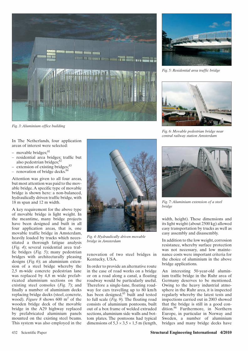
432 Scientific Paper Structural Engineering International 4/2010
In The Netherlands, four application areas of interest were selected:
– movable bridges;81
– residential area bridges; traffi c but also pedestrian bridges;82
– extension of existing bridges;83
– renovation of bridge decks.84
Attention was given to all four areas, but most attention was paid to the mov-able bridge. A specific type of movable bridge is shown here: a non-balanced, hydraulically driven traffic bridge, with 18 m span and 12 m width.
A key requirement for the above type of movable bridge is light weight. In the meantime, many bridge projects have been designed and built in all four application areas, that is, one movable traffic bridge in Amsterdam, heavily loaded by trucks which neces-sitated a thorough fatigue analysis (Fig. 4); several residential area traf-fic bridges (Fig. 5); many pedestrian bridges with architecturally pleasing designs (Fig. 6); an aluminium exten-sion of a steel bridge whereby the 2,5 m-wide concrete pedestrian lane was replaced by 4,8 m wide prefab-ricated aluminium sections on the existing steel consoles (Fig. 7); and finally a number of aluminium decks replacing bridge decks (steel, concrete, wood). Figure 8 shows 600 m2 of the wooden bridge deck of the movable bridge in the A29 highway replaced by prefabricated aluminium panels mounted on the existing steel beams. This system was also employed in the
Fig. 3: Aluminium office building
Fig. 4: Hydraulically driven movable bridge in Amsterdam
Fig. 7: Aluminium extension of a steel bridge
Fig. 6: Movable pedestrian bridge near central railway station Amsterdam
Fig. 5: Residential area traffic bridge
renovation of two steel bridges in Kentucky, USA.
In order to provide an alternative route in the case of road works on a bridge or on a road along a canal, a floating roadway would be particularly useful. Therefore a single-lane, floating road-way for cars travelling up to 80 km/h has been designed,85 built and tested to full scale (Fig. 9). The floating road consists of aluminium pontoons, built out of a box frame of welded extruded sections, aluminium side walls and bot-tom plates. The pontoons had typical dimensions of 5,3 × 3,5 × 1,5 m (length,
width, height). These dimensions and its light weight (about 2500 kg) allowed easy transportation by trucks as well as easy assembly and disassembly.
In addition to the low weight, corrosion resistance, whereby surface protection was not necessary, and low mainte-nance costs were important criteria for the choice of aluminium in the above bridge applications.
An interesting 50-year-old alumin-ium traffic bridge in the Ruhr area of Germany deserves to be mentioned. Owing to the heavy industrial atmo-sphere in the Ruhr area, it is inspected regularly whereby the latest tests and inspections carried out in 2003 showed that the bridge is still in a good con-dition.86 Furthermore, in Northern Europe, in particular in Norway and Sweden, a number of aluminium bridges and many bridge decks have
x011.indd 432x011.indd 432 28/10/10 10:40 AM28/10/10 10:40 AM
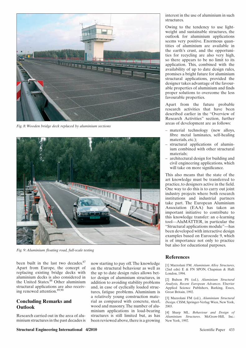
Structural Engineering International 4/2010 Scientific Paper 433
been built in the last two decades.87 Apart from Europe, the concept of replacing existing bridge decks with aluminium decks is also considered in the United States.88 Other aluminium structural applications are also receiv-ing renewed attention.89,90
Concluding Remarks and Outlook
Research carried out in the area of alu-minium structures in the past decades is
now starting to pay off. The knowledge on the structural behaviour as well as the up to date design rules allows bet-ter design of aluminium structures, in addition to avoiding stability problems and, in case of cyclically loaded struc-tures, fatigue problems. Aluminium is a relatively young construction mate-rial as compared with concrete, steel, wood and masonry. The number of alu-minium applications in load- bearing structures is still limited but, as has been reviewed above, there is a growing
interest in the use of aluminium in such structures.
Owing to the tendency to use light-weight and sustainable structures, the outlook for aluminium applications seems very positive. Enormous quan-tities of aluminium are available in the earth’s crust, and the opportuni-ties for recycling are also very high, so there appears to be no limit to its application. This, combined with the availability of up to date design rules, promises a bright future for aluminium structural applications, provided the designer takes advantage of the favour-able properties of aluminium and finds proper solutions to overcome the less favourable properties.
Apart from the future probable research activities that have been described earlier in the “Overview of Research Activities” section, further areas of development are as follows:
– material technology (new alloys, fi bre metal laminates, self-healing materials, etc.);
– structural applications of alumin-ium combined with other structural materials;
– architectural design for building and civil engineering applications, which will take on more signifi cance.
This also means that the state of the art knowledge must be transferred to practice, to designers active in the field. One way to do this is to carry out joint industry projects where both research institutions and industrial partners take part. The European Aluminium Association (EAA) has taken an important initiative to contribute to this knowledge transfer: an e-learning tool—AluMATTER, in particular the “Structural applications module”—has been developed with interactive design examples based on Eurocode 9, which is of importance not only to practice but also for educational purposes.
References
[1] Mazzolani FM. Aluminium Alloy Structures, (2nd edn) E & FN SPON, Chapman & Hall: London, 1994.
[2] Bulson PS (ed.), Aluminium Structural Analysis, Recent European Advances. Elsevier Applied Science Publishers, Barking, Essex, Great Britain, 1992.
[3] Mazzolani FM (ed.), Aluminium Structural Design. CISM, Springer-Verlag: Wien, New York, 2003.
[4] Sharp ML. Behaviour and Design of Aluminium Structures. McGraw-Hill, Inc.: New York, 1992.
Fig. 9: Aluminium floating road, full-scale testing
Fig. 8: Wooden bridge deck replaced by aluminium sections
x011.indd 433x011.indd 433 28/10/10 10:40 AM28/10/10 10:40 AM
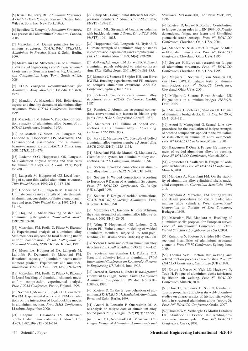
434 Scientific Paper Structural Engineering International 4/2010
[5] Kissell JR, Ferry RL. Aluminium Structures, A Guide to Their Specifications and Design. John Wiley & Sons, Inc.: New York, 1995.
[6] Beaulieu D. Design of Aluminium Structures. Les presses de l’aluminium: Chicoutimi, Canada, 2006.
[7] Mazzolani FM. Design principles for alu-minium structures, STAHLBAU SPEZIAL: Aluminium in Practice. Ernst & Sohn, Berlin, 1998.
[8] Mazzolani FM. Structural use of aluminium alloys in civil engineering. Proc. 2nd International Conference on Structural Engineering, Mechanics and Computation, Cape Town, South Africa, 2004.
[9] ECCS. European Recommendations for Aluminium Alloy Structures, 1st edn. Brussels, 1978.
[10] Mandara A, Mazzolani FM. Behavioural aspects and ductility demand of aluminium alloy structures. Proc. ICSAS Conference, Istanbul, 1995.
[11] Mazzolani FM, Piluso V. Prediction of rota-tion capacity of aluminium alloy beams. Proc. ICSAS Conference, Istanbul, 1995.
[12] de Matteis G, Moen LA, Langseth M, Landolfo R, Hopperstad OS, Mazzolani, FM. Cross-sectional classification for aluminium beams—parametric study. ASCE, J. Struct. Eng. 2001; 127(3): 271–279.
[13] Lademo O-G, Hopperstad OS, Langseth M. Evaluation of yield criteria and flow rules for aluminium alloys. Int. J. Plast. 1999; 15(2): 191–208.
[14] Langseth M, Hopperstad OS. Local buck-ling of square thin-walled aluminium structures. Thin-Walled Struct. 1997; 27(1): 117–126.
[15] Hopperstad OS, Langseth M, Hanssen L. Ultimate compressive strength of plate elements in aluminium: correlation of finite element anal-yses and tests. Thin-Walled Struct. 1997; 29(1–4): 31–46.
[16] Hoglund T. Shear buckling of steel and aluminium plate girders. Thin-Walled Struct. 1997; 29: 13–30.
[17] Mazzolani FM, Faella C, Piluso V, Rizzano G. Experimental analysis of aluminium alloy SHS-members subjected to local buckling under uniform compression, 5th Int. Colloquium on Structural Stability, SSRC, Rio de Janeiro, 1996.
[18] Moen LA, Hopperstad OS, Langseth M, Landolfo R, Dematteis G, Mazzolani FM. Rotational capacity of aluminium beams under moment gradient. Experiments and numerical simulations. J. Struct. Eng. 1999; 125(8): 921–929.
[19] Mazzolani FM, Faella C, Piluso V, Rizzano G. Local buckling of aluminium channels under uniform compression: experimental analysis, Proc. ICSAS Conference, Espoo, Finland, 1999.
[20] Soetens F, Mennink J, Snijder HH, van Hove BWEM. Experimental work and FEM calcula-tions on the interaction of local buckling modes in aluminium sections. Proc. SIMS Conference, Lissabon, September 2000.
[21] Chapuis J, Galambos TV. Restrained crooked aluminium columns. J. Struct. Div. ASCE 1982; 108(ST3): 511–524.
[22] Sharp ML. Longitudinal stiffeners for com-pression members. J. Struct. Div. ASCE 1966; 92(ST5): 187–211.
[23] Sharp ML. Strength of beams or columns with buckled elements J. Struct. Div. ASCE 1970; 96(ST5): 1011–1015.
[24] Hopperstad OS, Langseth M, Tryland T. Ultimate strength of aluminium alloy outstands in compression: experiments and simplified anal-ysis. Thin-Walled Struct. 1999; 34(4): 279–294.
[25] Aalberg A, Langseth M. Larsen PK Stiffened aluminium panels subjected to axial compres-sion. Thin-Walled Struct. 2001; 39(10): 861–885.
[26] Mennink J, Soetens F, Snijder HH, van Hove BWEM. Buckling experiments and FE-analyses on complex aluminium extrusions. ASSCCA Conference, Sydney, June 2003.
[27] Soetens F. Connections in aluminium alloy structures. Proc. ICSAS Conference, Cardiff, 1987.
[28] Ramirez J. Aluminium structural connec-tions, conventional slip factors in friction grip joints. Proc. ICSAS Conference, Cardiff, 1987.
[29] Menzemer CC. Failure of bolted con-nections in an aluminium alloy. J. Mater. Eng. Perform. ASM 1999; 8(2).
[30] May JE, Menzemer CC. Strength of bolted aluminium alloy tension members. J. Struct. Eng. ASCE 2005; 131(7): 1125–1134.
[31] Mazzolani FM, de Matteis G, Mandara A. Classification system for aluminium alloy con-nections, IABSE Colloquium, Istanbul, 1996.
[32] Soetens F. Welded connections in alumin-ium alloy structures. HERON 1987; 32: 1–48.
[33] Soetens F. Welded connections according to Eurocode 9 Design of Aluminium Structures. Proc. 7th INALCO Conference, Cambridge (UK), April 1998.
[34] Soetens F. Design of welded connections, STAHLBAU 67, Sonderheft Aluminium, Ernst & Sohn: Berlin, 1998.
[35] Menzemer CC, Iasconne R. Reestablishing the shear strength of aluminium alloy fillet welds Weld. J. 2002; 81(4): 29–31.
[36] Wang T, Hopperstad OS, Lademo O-G, Larsen PK. Finite element modelling of welded aluminium members subjected to four-point bending. Thin-Walled Struct. 2007; 45(3): 307–320.
[37] Soetens F. Adhesive joints in aluminium alloy structures. Int. J. Adhes. Adhes. 1990; 10: 146–152.
[38] Soetens, van Straalen IJJ, Dijkstra OD. Structural adhesive joints in aluminium. Third International Conference on Structural Adhesives in Engineering III, Bristol, June 1992.
[39] Jaccard R, Kosteas D, Ondra R. Background Document to Fatigue Design Curves for Welded Aluminium Components, IIW doc. No. XIII-1588-95, 1995.
[40] Kosteas D. On the fatigue behaviour of alu-minium. STAHLBAU 67, Sonderheft Aluminium, Ernst and Sohn: Berlin, 1998.
[41] Atzori B, Lazzarin P, Quaresimin M. A re-analysis on fatigue data of aluminium alloy bolted joints. Int. J. Fatigue 1997; 19(7): 579–588.
[42] Sharp ML, Nordmark GE, Menzemer CC. Fatigue Design of Aluminium Components and
Structures. McGraw-Hill, Inc.: New York, NY, 1996.
[43] Kosteas D, Jaccard R, Rothe J. Contribution to fatigue design rules in prEN 1999-1-3, R-ratio dependence, fatigue test factor and Simplified geometric stress concept. Proc. 9th INALCO Conference, Cleveland, Ohio, USA, 2004.
[44] Maddox SJ. Scale effect in fatigue of fillet welded aluminium alloys. Proc. 6th INALCO Conference, Cleveland, Ohio, USA, 1995.
[45] Soetens F. European research on fatigue of aluminium structures. Proc. 6th INALCO Conference, Cleveland, Ohio, USA, 1995.
[46] Maljaars J, Soetens F, van Straalen IJJ, van Hove BWEM. Fatigue tests on alumin-ium bridges. Proc. 9th INALCO Conference, Cleveland, Ohio, USA, 2004.
[47] Maljaars J, Soetens F, van Straalen, IJJ. Fatigue tests on aluminium bridges, HERON, Delft, 2005.
[48] Maljaars J, Soetens F, Straalen IJJ. Fatigue of aluminium bridge decks, Struct. Eng. Int. 2006; 16(4): 305–311.
[49] Atzori B, Meneghetti G, Susmel L. A new procedure for the evaluation of fatigue strength of notched components applied to the evaluation of scale effect in aluminium alloy weldments. Proc. 8th INALCO Conference, Munich, 2001.
[50] Haagensen P, Oma S. Fatigue life improve-ment of welded aluminium alloys by peening. Proc. 8th INALCO Conference, Munich, 2001.
[51] Orjasaeter O, Skallerud B. Fatigue of wide plate weldments. Proc. 8th INALCO Conference, Munich, 2001.
[52] Mandara A, Mazzolani FM. On the stabil-ity of aluminium alloy cylindrical shells under axial compression. Costruzioni Metalliche 1989; 2–3.
[53] Mandara A, Mazzolani FM. Testing results and design procedures for axially loaded alu-minium alloy cylinders. Proc. International Colloquium on Stability of Steel Structures, Budapest, 1990.
[54] Mazzolani FM, Mandara A. Buckling of aluminium shells: proposal for European curves. Proc. 4th International Conference on Thin-Walled Structures, Loughborough (UK), 2004.
[55] Kutanova N, Soetens F, Snijder HH. Cross-sectional instabilities of aluminium structural elements. Proc. CIMS Conference, Sydney, June 2008.
[56] Thomas WM. Friction stir welding and related friction process characteristics. Proc. 7th INALCO Conference, Cambridge (UK), 1998.
[57] Okura I, Naruo M, Vigh LG, Hagisawa N, Toda H. Fatigue of aluminium decks fabricated by friction stir welding. Proc. 8th INALCO Conference, Munich, 2001.
[58] Hori H, Tanikawa H, Seo N, Namba K. Tensile properties of friction stir welded joints—studies on characteristics of friction stir welded joints in structural aluminium alloys (report 3). Proc. 10th INALCO Conference, Osaka, 2007.
[59] Thomas WM, Verhaeghe G, Martin J. Staines DG, Stanhope C. Friction stir welding-pro-cess variants—an update. Proc. 10th INALCO Conference, Osaka, 2007.
x011.indd 434x011.indd 434 28/10/10 10:40 AM28/10/10 10:40 AM
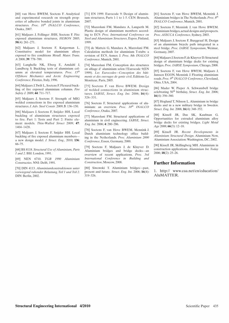
Structural Engineering International 4/2010 Scientific Paper 435
[60] van Hove BWEM, Soetens F. Analytical and experimental research on strength prop-erties of adhesive bonded joints in aluminium structures. Proc. 10th INALCO Conference, Osaka, 2007.
[61] Maljaars J, Fellinger JHH, Soetens F. Fire exposed aluminium structures, HERON 2005; 50(4): 261–271.
[62] Maljaars J, Soetens F, Katgerman L. Constitutive model for aluminium alloys exposed to fire conditions Metall. Mater. Trans. A 2008; 39: 778–789.
[63] Langhelle NK, Eberg E, Amdahl J, Lundberg S. Buckling tests of aluminium col-umns at elevated temperatures. Proc. 15th Offshore Mechanics and Arctic Engineering Conference, Firenze, Italy, 1996.
[64] Maljaars J, Twilt L, Soetens F. Flexural buck-ling of fire exposed aluminium columns. Fire Safety J. 2009; 44: 711–717.
[65] Maljaars J, Soetens F. Strength of MIG welded connections in fire exposed aluminium structures. J. Adv. Steel Constr. 2009; 5: 136–150.
[66] Maljaars J, Soetens F, Snijder HH, Local buckling of aluminium structures exposed to fire. Part 1: Tests and Part 2: Finite ele-ment models. Thin-Walled Struct 2009; 47: 1404–1428.
[67] Maljaars J, Soetens F, Snijder HH. Local buckling of fire exposed aluminium members—a new design model. J. Struct. Eng., 2010; 136: 66–75.
[68] BS 8118. Structural Use of Aluminium, Parts 1 and 2. BSI: London, 1991.
[69] NEN 6710. TGB 1990 Aluminium Constructies. NNI: Delft, 1991.
[70] DIN 4113. Aluminiumkonstruktionen unter vorwiegend ruhender Belastung, Teil 1 und Teil 2. DIN: Berlin, 2002.
[71] EN 1999. Eurocode 9: Design of alumin-ium structures, Parts 1-1 to 1-5. CEN: Brussels, 2007.
[72] Mazzolani FM, Mandara A, Langseth M. Plastic design of aluminium members accord-ing to EC9. Proc. International Conference on Steel and Aluminium Structures, Espoo, Finland, 1999.
[73] de Matteis G, Mandara A, Mazzolani FM. Calculation methods for aluminium T-stubs: a revision of EC9, Annex J. Proc. 8th INALCO Conference, Munich, 2001.
[74] Mazzolani FM. Conception des structures en alliage d’ aluminium selon l’Eurocode 9(EN 1999). Les Eurocodes—Conception des bâti-ments et des ouvrages de genie civil, Editions Le Moniteur, Paris, 2005.
[75] Soetens F. van Hove BWEM. Design of welded connections in aluminium struc-tures. IABSE, Struct. Eng. Int. 2006; 16(4): 326–331.
[76] Soetens F, Structural applications of alu-minium: an overview. Proc. 10th INALCO Conference, Osaka, 2007.
[77] Mazzolani FM. Structural applications of aluminium in civil engineering. IABSE, Struct. Eng. Int. 2006; 4: 280–286.
[78] Soetens F, van Hove BWEM, Mennink J. Dutch aluminium technology office build-ing in the Netherlands. Proc. Aluminium 2000 Conference, Essen, Germany, 2000.
[79] Soetens F, Maljaars J, de Kluyver D. Aluminium bridges and bridge decks—an overview of recent applications. Proc. 3rd International Conference in Building and Construction, Moscow, 2008.
[80] Siwowski T. Aluminium bridges—past, present and future. Struct. Eng. Int. 2006; 16(4): 319–326.
[81] Soetens F, van Hove BWEM, Mennink J. Aluminium bridges in The Netherlands. Proc. 8th INALCO Conference, Munich, 2001.
[82] Soetens F, Mennink J, van Hove BWEM. Aluminium bridges, actual designs and prospects. Proc. ASSCCA Conference, Sydney, 2003.
[83] Maljaars J, Soetens F, Burggraaf H, Design of an aluminium bicycle path integrated in a steel bridge. Proc. IABSE Symposium, Weimar, Germany, 2007.
[84] Maljaars J, Soetens F, de Kluyver D. Structural design of aluminium bridge decks for existing bridges. Proc. IABSE Symposium, Chicago, 2008.
[85] Soetens F, van Hove BWEM, Maljaars J, Janssen EGON, Mennink J. Floating aluminium roads. Proc. 9th INALCO Conference, Cleveland, Ohio, USA, 2004.
[86] Mader W, Pieper A. Schwansbell bridge celebrating 50th birthday, Struct. Eng. Int. 2006; 16(4): 356–360.
[87] Hoglund T, Nilsson L. Aluminium in bridge decks and in a new military bridge in Sweden. Struct. Eng. Int. 2006; 16(4): 348–352.
[88] Kissell JR, Das SK, Kaufman G. Opportunities for extruded aluminium alloy bridge decks for existing bridges. Light Metal Age 2008; 66(3): 12–18.
[89] Kissell JR. Recent Developments in Aluminium Structural Design. Aluminium Now, Aluminium Association: Washington, DC, 2002.
[90] Kissell JR, Skillingberg MH. Aluminium in construction applications. Aluminium Int. Today 2006; 18(2): 25–26.
Further Information
1. http:// www.eaa.net/en/education/ AluMATTER.
x011.indd 435x011.indd 435 28/10/10 10:40 AM28/10/10 10:40 AM

436 Scientific Paper Structural Engineering International 4/2010
Peer-reviewed by international ex-perts and accepted for publication by SEI Editorial Board
Paper received: March 04, 2010Paper accepted: June 29, 2010
Glass Tensegrity TrussesMaurizio Froli, Prof.; Leonardo Lani, Dr-Ing.; Department of Civil Engineering, University of Pisa,
Pisa, Italy. Contact: [email protected]
the application of this principle also ensures a pseudo-ductile behaviour: it is known that if a glass sheet breaks, the other sheets are still able to bear the load, and even if all the sheets break into large fragments, (only fully thermally tempered glass breaks into many small fragments), the redundant sandwich structure assures a post-breakage stiffness and bearing capac-ity of the component that is similar, to some extent, to material ductility.4
For these reasons, a suitable applica-tion of the two basic principles of hier-archy and redundancy can provide a structure with decisive properties of global ductility and fail-safe design even if mostly composed of glass com-ponents. Fig. 1 shows the structural organization of the present type of glass beams.
Additionally, if the integrity of the structure is enhanced by prestressing, compression stresses superimpose in glass elements to those produced by tempering, thus increasing the appar-ent tensile strength of the material.
Structural Conceptual Design of Trabes Vitreae Tensegrity Beams
Experiments reveal that when a tra-ditional glass beam is submitted to increasing flexural loads, it cracks at a certain load, developing characteris-tic crack patterns. To avoid an uncon-trolled process of crack initiation and propagation, the idea considered was to govern it by regularly pre-cutting the glass surface into many equilateral triangle panes and connecting them together using a system of prestressed steel cables.
The principle of tensegrity permeates this concept, therefore it was decided to call these beams Trabes Vitreae Tensegrity or TVT, mixing Latin and English words.
Each triangular pane is composed of two 5 mm thick chemically tempered glass sheets5 laminated by means of a 1,52 mm thick PolyVinylButyral (PVB) interlayer.
The beam is composed of two paral-lel twin curtains 174 mm apart, braced on the upper side by a horizontal truss
of glass1 and for its relative low ten-sile strength. An apparent higher ten-sile strength is obtained by thermal or chemical tempering treatments, which induce surface compression stresses that inhibit crack initiation and propa-gation but do not exert any influence on fragility.2
Prestressed Composite Glass Beams
Basic Concepts
The intrinsic fragility of glass may be overcome by organizing the whole structure in two or more hierarchic levels, each of them composed of a parallel, redundant assemblage of at least two structural components.
The hierarchic organization of the components ensures that the sequence of progressive damage follows a pre-established order starting from the level where the weakest components are. Therefore, if we put ductile mate-rials at the lowest level, we can be sure that the failure process will start from here accompanied by large plas-tic deformations, that is, with a global ductile behaviour.
On the other hand, redundancy ensures at each level that, when a sin-gle component fails, the other partner components are still able to bear the load although with a reduced degree of safety.3 In laminated glass panes,
Introduction
Ductility is usually associated with metallic materials that are capable of developing large plastic deformations. On the other hand, fragility is tradi-tionally associated with glass materials or ceramics.
Nevertheless, some outstanding and innovative glass structures, like the Haus Pavilion in Rheinbach the Yurakucho canopy in Tokyo, the glass stairs of the Apple Stores in San Francisco, have been built even in seis-mic areas where fragile failures must be definitely avoided.
Indeed, although glass is fragile and weakly tension resistant, it has a very high compressive strength and, if con-veniently connected with other duc-tile materials, for example, by means of gluing or by prestressing, it is able to form composite structures of high mechanical performances and also global ductility.
It is well known that stress concen-trations that occur at the apex of microscopic surface cracks, always present even in virgin specimens, are responsible for the intrinsic fragility
Abstract
High transparency and modularity, retarded first cracking, non-brittle collapse and fail-safe design were the basic requirements that inspired and guided the development of a new kind of glass beams. The two basic conceptual design goals were to avoid any cracking at service and to get a ductile behaviour at failure. These objectives were reached by a preliminary subdivision of the beam into many small triangular laminated panes and by assembling them together by means of prestressed steel cables. Two prototypes have been constructed at the University of Pisa, tested in the elastic domain under dynamics loads and succes-sively brought to collapse under quasi-static, increasing load cycles. In order to investigate the decay process of residual mechanical resources, the second pro-totype has been repaired twice by substituting just the damaged triangular panes and then tested again each time up to failure. Experimental results resulted in a good agreement with non-linear numerical simulations performed by appropri-ate finite element modelling.
Keywords: structural glass; prestressed glass structures; post-breakage behaviour; structural ductility; fail-safe design; chemical tempering; fracture mechanics.
x065.indd 436x065.indd 436 10/25/10 11:08 PM10/25/10 11:08 PM
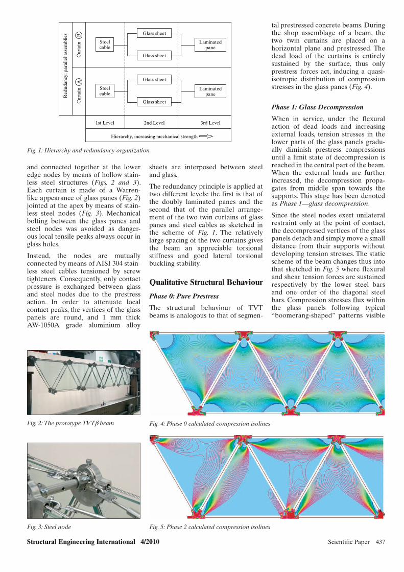
Structural Engineering International 4/2010 Scientific Paper 437
tal prestressed concrete beams. During the shop assemblage of a beam, the two twin curtains are placed on a horizontal plane and prestressed. The dead load of the curtains is entirely sustained by the surface, thus only prestress forces act, inducing a quasi-isotropic distribution of compression stresses in the glass panes (Fig. 4).
Phase 1: Glass Decompression
When in service, under the flexural action of dead loads and increasing external loads, tension stresses in the lower parts of the glass panels gradu-ally diminish prestress compressions until a limit state of decompression is reached in the central part of the beam. When the external loads are further increased, the decompression propa-gates from middle span towards the supports. This stage has been denoted as Phase 1—glass decompression.
Since the steel nodes exert unilateral restraint only at the point of contact, the decompressed vertices of the glass panels detach and simply move a small distance from their supports without developing tension stresses. The static scheme of the beam changes thus into that sketched in Fig. 5 where flexural and shear tension forces are sustained respectively by the lower steel bars and one order of the diagonal steel bars. Compression stresses flux within the glass panels following typical “boomerang-shaped” patterns visible
sheets are interposed between steel and glass.
The redundancy principle is applied at two different levels: the first is that of the doubly laminated panes and the second that of the parallel arrange-ment of the two twin curtains of glass panes and steel cables as sketched in the scheme of Fig. 1. The relatively large spacing of the two curtains gives the beam an appreciable torsional stiffness and good lateral torsional buckling stability.
Qualitative Structural Behaviour
Phase 0: Pure Prestress
The structural behaviour of TVT beams is analogous to that of segmen-
and connected together at the lower edge nodes by means of hollow stain-less steel structures (Figs. 2 and 3). Each curtain is made of a Warren-like appearance of glass panes (Fig. 2) jointed at the apex by means of stain-less steel nodes (Fig. 3). Mechanical bolting between the glass panes and steel nodes was avoided as danger-ous local tensile peaks always occur in glass holes.
Instead, the nodes are mutually connected by means of AISI 304 stain-less steel cables tensioned by screw tighteners. Consequently, only contact pressure is exchanged between glass and steel nodes due to the prestress action. In order to attenuate local contact peaks, the vertices of the glass panels are round, and 1 mm thick AW-1050A grade aluminium alloy
Red
udan
cy, p
aral
lel a
ssem
blie
s
Cur
tain
AC
urta
inB
Steelcable
Glass sheet
Laminatedpane
Laminatedpane
Glass sheet
Glass sheet
Glass sheet
Hierarchy, increasing mechanical strength
Steelcable
1st Level 2nd Level 3rd Level
Fig. 1: Hierarchy and redundancy organization
Fig. 2: The prototype TVTb beam
Fig. 3: Steel node
Fig. 4: Phase 0 calculated compression isolines
Fig. 5: Phase 2 calculated compression isolines
x065.indd 437x065.indd 437 10/25/10 11:08 PM10/25/10 11:08 PM

438 Scientific Paper Structural Engineering International 4/2010
1000,00 N
1000,00 N
1000,00 N
1000,00 N
Y
X
Fig. 6: Global model of TVTb
in the same graph. Only secondary tension stresses of lower intensity affects glass.
Phase 2: Buckling of Upper Cables
Compressed steel cables are gradually de-tensioned: when the prestress load is fully compensated, they buckle away. This limit state has been denoted as Phase 2—buckling phase.
Phase 3: Collapse
After Phase 2 has been reached, a fur-ther increase in load leads to an aug-mentation of stress compressions in the glass panes and tension stresses in the steel rods. The dimensioning of the different component parts of the beam can be performed so that the final Phase 3—collapse takes place due to the yielding of the steel cables and not because of glass rupture in compres-sion, thus resulting in a ductile collapse accompanied by large displacements.
Depending on the slenderness of the steel cables and on the prestress inten-sity, Phase 2 may even follow Phase 3, as indeed happened in the prototype beam, and illustrated in the following text.
Numerical Modelling
Four different finite element model (FEM) analyses have been performed to predict the various aspects of the structural behaviour of the beam and to better calibrate the design of the prototypes (Fig. 6):
– 2D non-linear geometrical analysis to evaluate the effect of prestress on the fl exural stiffness of the beam;
– 2D local buckling analysis to evalu-ate instability effects of prestress for each single glass pane;
– 3D local geometric non-linear anal-ysis to evaluate the transversal stiff-ness of the different joints;
– 3D geometric non-linear analysis to evaluate the torsional stiffness of the beam.
The glass panels have been modelled by Shell elements (4-node, 24 degrees of freedom) while the steel cables have been reproduced by Bar ele-ments (2-node, 6 degrees of freedom) that react only to tension stresses. The constitutive laws for the two materials have been deduced from European Code6, that is, glass has been schema-tized as a linear brittle elastic material and stainless steel as linear elastic–plastic material with a linear harden-ing branch.
In order to model contacts between glass panels and steel nodes a set of point contact elements was introduced that were capable of reacting just to compression stresses. Aluminium sheets were not included in the model because of their relatively small thick-ness and, for practical reasons, owing to the coincidence of the Young’s moduli of aluminium and glass. The transversal stiffness of the joint was preliminarily investigated by a 3D local model with solid elements (8-node, 24 degree of freedom) (Fig. 7).
Calculations have substantially con-firmed the intuitive predictions syn-thetically described in the section Qualitative Structural Behaviour with the only exception that the buckling phase of upper steel cables (Phase 2) does not influence significantly the flexural response of the beam (Fig. 8). On the other hand, the decompression phase (Phase 1) and the yielding phase (Phase 3) of the lower steel cables can be clearly recognized.
Figure 9 shows the load factor versus displacement of the middle span point for different prestress (from 2 to 12 kN) Np load in the steel cables, assum-ing P = 1 kN, the force applied to each of the eight nodes of the beam, corre-sponds to a load factor one. The first stiffness reduction is associated with the decompression of the lower part of the beam (Phase 1). By increasing the prestress level, the intensity of the external load that induces the decom-pression phase increases. The second step of stiffness decay is associated with the yielding of the lower steel cable but, of course, the ultimate limit load results independent of Np.
Figure 10 shows the influence of Np on the axial force in the lower cable of the beam, and how the ultimate load is independent on the value of prestress.
The hardening properties of stainless steel allowed the analysis to progress beyond the yield initiation of the lower bars until the buckling of the upper bars and of the middle span glass panels.
x065.indd 438x065.indd 438 10/25/10 11:08 PM10/25/10 11:08 PM
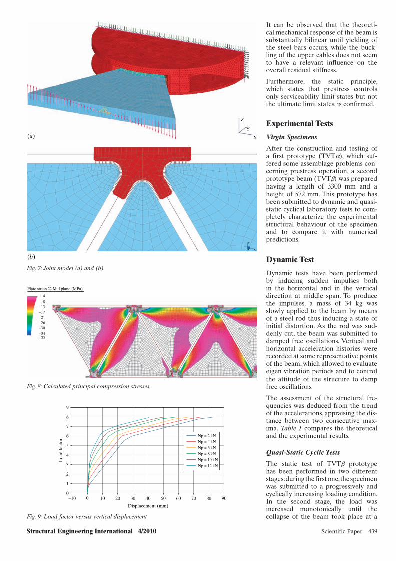
Structural Engineering International 4/2010 Scientific Paper 439
It can be observed that the theoreti-cal mechanical response of the beam is substantially bilinear until yielding of the steel bars occurs, while the buck-ling of the upper cables does not seem to have a relevant influence on the overall residual stiffness.
Furthermore, the static principle, which states that prestress controls only serviceability limit states but not the ultimate limit states, is confirmed.
Experimental Tests
Virgin Specimens
After the construction and testing of a first prototype (TVTa), which suf-fered some assemblage problems con-cerning prestress operation, a second prototype beam (TVTb) was prepared having a length of 3300 mm and a height of 572 mm. This prototype has been submitted to dynamic and quasi-static cyclical laboratory tests to com-pletely characterize the experimental structural behaviour of the specimen and to compare it with numerical predictions.
Dynamic Test
Dynamic tests have been performed by inducing sudden impulses both in the horizontal and in the vertical direction at middle span. To produce the impulses, a mass of 34 kg was slowly applied to the beam by means of a steel rod thus inducing a state of initial distortion. As the rod was sud-denly cut, the beam was submitted to damped free oscillations. Vertical and horizontal acceleration histories were recorded at some representative points of the beam, which allowed to evaluate eigen vibration periods and to control the attitude of the structure to damp free oscillations.
The assessment of the structural fre-quencies was deduced from the trend of the accelerations, appraising the dis-tance between two consecutive max-ima. Table 1 compares the theoretical and the experimental results.
Quasi-Static Cyclic Tests
The static test of TVTb prototype has been performed in two different stages: during the first one, the specimen was submitted to a progressively and cyclically increasing loading condition. In the second stage, the load was increased monotonically until the collapse of the beam took place at a
X
Y
Z
Y
XZ
(a)
(b)
Fig. 7: Joint model (a) and (b)
Plate stress 22 Mid plane (MPa)
−4−8
−13−17−21−26−30−34−35
Fig. 8: Calculated principal compression stresses
9
8
7
6
5
4
Loa
d fa
ctor
3
2
1
0−10 0 10 20 30
Displacement (mm)
40 50 60 70 80 90
Np = 2 kN
Np = 4 kN
Np = 6 kN
Np = 8 kN
Np = 10 kN
Np = 12 kN
Fig. 9: Load factor versus vertical displacement
x065.indd 439x065.indd 439 10/25/10 11:08 PM10/25/10 11:08 PM
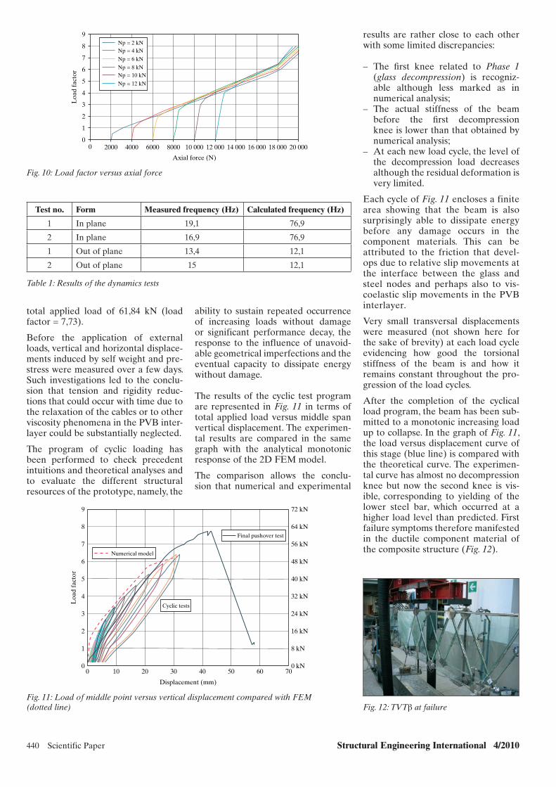
440 Scientific Paper Structural Engineering International 4/2010
results are rather close to each other with some limited discrepancies:
– The fi rst knee related to Phase 1 (glass decompression) is recogniz-able although less marked as in numerical analysis;
– The actual stiffness of the beam before the fi rst decompression knee is lower than that obtained by numerical analysis;
– At each new load cycle, the level of the decompression load decreases although the residual deformation is very limited.
Each cycle of Fig. 11 encloses a finite area showing that the beam is also surprisingly able to dissipate energy before any damage occurs in the component materials. This can be attributed to the friction that devel-ops due to relative slip movements at the interface between the glass and steel nodes and perhaps also to vis-coelastic slip movements in the PVB interlayer.
Very small transversal displacements were measured (not shown here for the sake of brevity) at each load cycle evidencing how good the torsional stiffness of the beam is and how it remains constant throughout the pro-gression of the load cycles.
After the completion of the cyclical load program, the beam has been sub-mitted to a monotonic increasing load up to collapse. In the graph of Fig. 11, the load versus displacement curve of this stage (blue line) is compared with the theoretical curve. The experimen-tal curve has almost no decompression knee but now the second knee is vis-ible, corresponding to yielding of the lower steel bar, which occurred at a higher load level than predicted. First failure symptoms therefore manifested in the ductile component material of the composite structure (Fig. 12).
total applied load of 61,84 kN (load factor = 7,73).
Before the application of external loads, vertical and horizontal displace-ments induced by self weight and pre-stress were measured over a few days. Such investigations led to the conclu-sion that tension and rigidity reduc-tions that could occur with time due to the relaxation of the cables or to other viscosity phenomena in the PVB inter-layer could be substantially neglected.
The program of cyclic loading has been performed to check precedent intuitions and theoretical analyses and to evaluate the different structural resources of the prototype, namely, the
T est no. Form Measured frequency (Hz) Calculated frequency (Hz)
1 In plane 19,1 76,9
2 In plane 16,9 76,9
1 Out of plane 13,4 12,1
2 Out of plane 15 12,1
Table 1: Results of the dynamics tests
Np = 2 kNNp = 4 kN
Np = 6 kN
Np = 8 kNNp = 10 kN
Np = 12 kN
9
8
7
6
5
4
Loa
d fa
ctor
3
2
1
00 2000 4000 6000 8000 10 000 12 000
Axial force (N)
14 000 16 000 18 000 20 000
Fig. 10: Load factor versus axial force
ability to sustain repeated occurrence of increasing loads without damage or significant performance decay, the response to the influence of unavoid-able geometrical imperfections and the eventual capacity to dissipate energy without damage.
The results of the cyclic test program are represented in Fig. 11 in terms of total applied load versus middle span vertical displacement. The experimen-tal results are compared in the same graph with the analytical monotonic response of the 2D FEM model.
The comparison allows the conclu-sion that numerical and experimental
9 72 kN
64 kN
56 kN
48 kN
40 kN
32 kN
24 kN
16 kN
8 kN
0 kN
8
7
6
5
4
Loa
d fa
ctor
3
2
1
00 10 20 30
Displacement (mm)
40 50 60 70
Numerical model
Cyclic tests
Fig. 11: Load of middle point versus vertical displacement compared with FEM (dotted line) Fig. 12: TVTβ at failure
x065.indd 440x065.indd 440 10/25/10 11:08 PM10/25/10 11:08 PM
Final pushover test

Structural Engineering International 4/2010 Scientific Paper 441
age after buckling, they could not offer the same degree of restraint as the vir-gin ones.
Therefore, the central panels of TVTbbis buckled corresponding to a load factor of 4 instead of the previous 7,5.
Next, in prototype TVTbbis, the col-lapsed central panels were substituted. The second repaired prototype was called TVTb tris and exhibited almost the same ultimate load factor as the precedent version.
Figure 13 shows the load factor ver-sus middle span vertical displacement cycles of the virgin specimen and of the two repaired versions. A rather good retention of the stiffness proper-ties of the repaired specimens can be observed together with a progressive increase in the dissipated energy.
Owing to the hardening proper-ties of stainless steel, the load can be increased even beyond yielding: the final collapse of the specimen was reached when the upper parts of mid-dle span glass panels buckled away.
Repaired Specimens
After prototype TVTb completely collapsed as a consequence of the breaking of middle span panels, it was repaired by substituting just the bro-ken panels. Prestress was restored at the same levels of the virgin specimen TVTb.
The first repaired prototype was labeled as TVTbbis and submitted to the same increasing load cycles of TVTb.
Since the clam plates of the central panels in TVTb resulted in a little dam-
Fig. 13: Displacement origins have been shifted to the right in TVTbbis/tris
7
6
5
4
3
2
1
0−5 0 5 10 15 20
Displacement (mm)
25 30 35 40 45 50 55 60 650 kN
8 kN
16 kN
24 kN
32 kN
40 kN
48 kN
56 kNL
oad
fact
or
TVTβ
TVTβbis TVTβtris
Conclusion
The numerical results and the test experiments on virgin TVTb prototype of a prestressed composite glass–steel beam allow the conclusion that the constructional principle is valid and merits further technological improve-ment and research work.
The experimental and numerical results have underlined that TVT com-posite glass–steel beams are able to develop a ductile break-up and that the serviceability limit state is governed by the level of prestress in the steel cables. The cyclic load programme also evi-denced that these glass beams are able to dissipate energy through friction and viscoelasticity without damage.
The segmental, modular features and the tensile integrity of these beams allow substitutions to be limited just to the collapsed or cracked panels, thus reducing repair costs.
References
[1] Mencik J. Strength and Fracture of Glass and Ceramics. Elsevier: London, 1992.
[2] Sedlacek G. Ein Bemessungskonzept zur Festigkeit thermisch vorgespannter Gläser. Shaker Verlag: Aachen, 2000.
[3] Rice P, Dutton H. Structural Glass, 2nd edn. Spon Press: London, 2004.
[4] Kott A, Vogel T. Safety of laminated glass structures after initial failure. IABSE Struct. Eng. Int. 2004; 14(2): 134–138).
[5] Macrelli G. Process control methods for chem-ical strengthening of glass on industrial scale. Proc. XIX Int. Cong. Glass, Edinburgh, 2001.
[6] EN572 – Glass in Building, Basic Soda Lime Silicate Glass Products, Definitions and General Physical and Mechanical Properties, CEN/TC 129 Glass in Building, 2004.
x065.indd 441x065.indd 441 10/25/10 11:08 PM10/25/10 11:08 PM
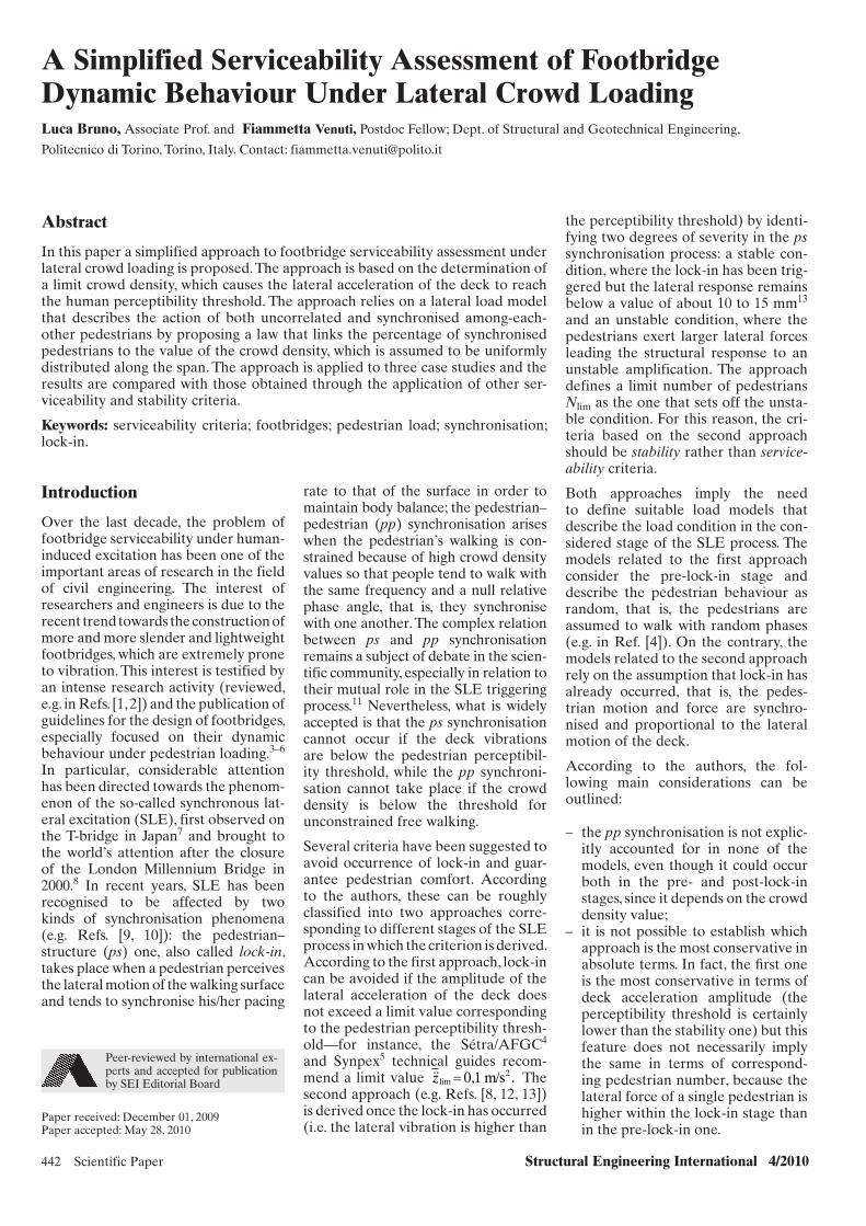
442 Scientific Paper Structural Engineering International 4/2010
Peer-reviewed by international ex-perts and accepted for publication by SEI Editorial Board
Paper received: December 01, 2009Paper accepted: May 28, 2010
A Simplified Serviceability Assessment of Footbridge Dynamic Behaviour Under Lateral Crowd LoadingLuca Bruno, Associate Prof. and Fiammetta Venuti, Postdoc Fellow; Dept. of Structural and Geotechnical Engineering,
Politecnico di Torino, Torino, Italy. Contact: [email protected]
Abstract
In this paper a simplified approach to footbridge serviceability assessment under lateral crowd loading is proposed. The approach is based on the determination of a limit crowd density, which causes the lateral acceleration of the deck to reach the human perceptibility threshold. The approach relies on a lateral load model that describes the action of both uncorrelated and synchronised among-each-other pedestrians by proposing a law that links the percentage of synchronised pedestrians to the value of the crowd density, which is assumed to be uniformly distributed along the span. The approach is applied to three case studies and the results are compared with those obtained through the application of other ser-viceability and stability criteria.
Keywords: serviceability criteria; footbridges; pedestrian load; synchronisation; lock-in.
rate to that of the surface in order to maintain body balance; the pedestrian–pedestrian (pp) synchronisation arises when the pedestrian’s walking is con-strained because of high crowd density values so that people tend to walk with the same frequency and a null relative phase angle, that is, they synchronise with one another. The complex relation between ps and pp synchronisation remains a subject of debate in the scien-tific community, especially in relation to their mutual role in the SLE triggering process.11 Nevertheless, what is widely accepted is that the ps synchronisation cannot occur if the deck vibrations are below the pedestrian perceptibil-ity threshold, while the pp synchroni-sation cannot take place if the crowd density is below the threshold for unconstrained free walking.
Several criteria have been suggested to avoid occurrence of lock-in and guar-antee pedestrian comfort. According to the authors, these can be roughly classified into two approaches corre-sponding to different stages of the SLE process in which the criterion is derived. According to the first approach, lock-in can be avoided if the amplitude of the lateral acceleration of the deck does not exceed a limit value corresponding to the pedestrian perceptibility thresh-old—for instance, the Sétra/AFGC4 and Synpex5 technical guides recom-mend a limit value ��zlim
2= 0,1 m/s . The second approach (e.g. Refs. [8, 12, 13]) is derived once the lock-in has occurred (i.e. the lateral vibration is higher than
the perceptibility threshold) by identi-fying two degrees of severity in the ps synchronisation process: a stable con-dition, where the lock-in has been trig-gered but the lateral response remains below a value of about 10 to 15 mm13 and an unstable condition, where the pedestrians exert larger lateral forces leading the structural response to an unstable amplification. The approach defines a limit number of pedestrians Nlim as the one that sets off the unsta-ble condition. For this reason, the cri-teria based on the second approach should be stability rather than service-ability criteria.
Both approaches imply the need to define suitable load models that describe the load condition in the con-sidered stage of the SLE process. The models related to the first approach consider the pre-lock-in stage and describe the pedestrian behaviour as random, that is, the pedestrians are assumed to walk with random phases (e.g. in Ref. [4]). On the contrary, the models related to the second approach rely on the assumption that lock-in has already occurred, that is, the pedes-trian motion and force are synchro-nised and proportional to the lateral motion of the deck.
According to the authors, the fol-lowing main considerations can be outlined:
– the pp synchronisation is not explic-itly accounted for in none of the models, even though it could occur both in the pre- and post-lock-in stages, since it depends on the crowd density value;
– it is not possible to establish which approach is the most conservative in absolute terms. In fact, the fi rst one is the most conservative in terms of deck acceleration amplitude (the perceptibility threshold is certainly lower than the stability one) but this feature does not necessarily imply the same in terms of correspond-ing pedestrian number, because the lateral force of a single pedestrian is higher within the lock-in stage than in the pre-lock-in one.
Introduction
Over the last decade, the problem of footbridge serviceability under human-induced excitation has been one of the important areas of research in the field of civil engineering. The interest of researchers and engineers is due to the recent trend towards the construction of more and more slender and lightweight footbridges, which are extremely prone to vibration. This interest is testified by an intense research activity (reviewed, e.g. in Refs. [1, 2]) and the publication of guidelines for the design of footbridges, especially focused on their dynamic behaviour under pedestrian loading.3–6 In particular, considerable attention has been directed towards the phenom-enon of the so-called synchronous lat-eral excitation (SLE), first observed on the T-bridge in Japan7 and brought to the world’s attention after the closure of the London Millennium Bridge in 2000.8 In recent years, SLE has been recognised to be affected by two kinds of synchronisation phenomena (e.g. Refs. [9, 10]): the pedestrian– structure (ps) one, also called lock-in, takes place when a pedestrian perceives the lateral motion of the walking surface and tends to synchronise his/her pacing
x015_cs2.indd 442x015_cs2.indd 442 10/28/10 1:22:21 PM10/28/10 1:22:21 PM

Structural Engineering International 4/2010 Scientific Paper 443
In this paper an alternative approach to footbridge serviceability assess-ment under lateral crowd loading is proposed. This approach is based on the consideration that the two con-cepts of limit values could be linked, that is, the limit number of pedestri-ans may be interpreted as the num-ber of pedestrians that induce the limit value of the acceleration. The positive aspects of the two approaches are therefore retained: on one hand, the definition of a critical number of pedestrians could be useful for the designer and the footbridge owner in view of the development of control strategies to limit the flow of pedes-trians; on the other hand, the analysis of the pre-lock-in stage is expected to be more relevant in order to predict and prevent the occurrence of SLE. The approach is accompanied by the proposal of a load model within the pre-lock-in stage that also accounts for the pp synchronisation due to crowd density. In the following, the proposed force model and comfort criterion are described and compared with other serviceability/stability criteria found in the literature through their applica-tion to some case studies.
Proposed Approach
The proposed approach is based on the derivation of a critical crowd den-sity r lim, which causes the lateral accel-eration of the deck to reach the limit value ��zlim .= 0,1 m/s2 This limit value corresponds to the pedestrian per-ceptibility threshold recommended by Sétra/AFGC4 and Butz et al.5, that is, to the upper bound of the pre-lock-in stage. The following assumptions have been adopted:
1. The structural response can be esti-mated with suffi cient accuracy using a single-degree-of-freedom (SDOF) modal equation for the mode of interest.
2. The deck mass is constant along the footbridge span.
3. The crowd is uniformly distributed along the span, so that both the crowd mass and the force exerted are constant in space. The force is applied on the deck so that its sign matches the sign of the deformed shape.
4. The pre-lock-in stage is consid-ered, that is, the pedestrians are not synchronised to the bridge motion, but they could be synchronised among each other owing to crowd density.
It follows that the critical value of the crowd density r lim refers to pedestri-ans uniformly distributed along the footbridge walking path, that is, to a load condition widely adopted in the footbridge design and corresponding to a uniform crowd flow.
The structural dynamics is described by the SDOF equation of motion as follows:
�� �Z t Z t Z tF tM
( ) ( ) ( )( )+ + =2ξω ωs s
2 (1)
in which Z(t) is the generalized coordi-nate expressing the motion of the sys-tem, t, the time, being the independent variable; z is the damping ratio; ws = 2πfs is the natural circular frequency of the mode of interest; F(t) and M are the generalised force and mass, respec-tively, expressed as follows:
F t f t x xL
( ) ( ) ( )= ∫ ϕ d0
(2)
M m x xL
= ∫ ϕ( )2
0d (3)
where L is the length of the footbridge deck, x is the space coordinate along the longitudinal axis of the footbridge, j (x) is the mode shape, f(t) and m are the force and mass per unit length, which are constant in space according to hypotheses 2 and 3.
The mass m is intended to be the over-all mass of the structure and crowd systems:
m m m m BG= + =s p p, with( ) ( )ρ ρ ρ (4)
where the subscripts s and p refer to the structure and pedestrians, respec-tively, r (ped/m2) is the crowd density, G = 70 kg is the average mass of one pedestrian and B is the width of the walking path.
The lateral force f(t) per unit length is expressed on the basis of the load model proposed by Venuti et al.10 and Venuti and Bruno.14 The original force model had been conceived to account for both pp and ps synchronisation and to describe the crowd force during the triggering, self-exciting and self-limiting SLE stages. According to the above-mentioned simplifying assump-tions, the lateral force model reduces to the following:
f t B F t( ) sin( )= ⋅ρ ωeq p0 (5)
with
ρeq eq= N BL/( ) (6)
and
N N S N Seq pp pp= + −( )1 (7)
where req is the equivalent crowd den-sity; F0 = 28 N is the amplitude of the lateral force exerted by one pedestrian; wp = 2πfp is the circular lateral walk-ing frequency; N = rBL is the number of pedestrians on the deck; Spp is the coefficient of synchronisation among pedestrians. The square root term in Eq. (7) represents the contribution of uncorrelated pedestrians, accord-ing to the model of Matsumoto et al.15 The lateral walking frequency fp is expressed as a function of the walk-ing velocity v, in turn dependent on the crowd density, according to the following laws:
f v v vp , , , /= − +( )2 93 1 59 0 35 22 3 (8)
v v= − − −⎛⎝⎜
⎞⎠⎟
⎡
⎣⎢
⎤
⎦⎥
⎧⎨⎪
⎩⎪
⎫⎬⎪
⎭⎪M
M
11 1
exp γρ ρ (9)
where the values of the coefficient g, the free speed vM and the jam density rM are made sensitive to different travel purposes (L = leisure/shopping, C = com-muters/events, R = rush hour/business) and geographic areas (E = Europe, U = USA, A = Asia) (Fig. 1). The laws in Eqs. (8) and (9), first proposed by Venuti and Bruno,16 are fitted to the experimental data reported in Refs. [5, 17, 18]. The values of the empirical parameters g, nM, rM of interest for the case studies discussed in the following section are reported in Table 2.
As far as the synchronisation coef-ficient Spp is concerned, in the last 2 years some new studies5,19,20 concern-ing pp synchronisation due to crowd density have been carried out by means of experimental tests performed within different ranges of crowd density. Araújo et al.19 found that, in the crowd density range from 0,3 to 0,9 ped/m2, there is no evidence of synchronisation among pedestrians, since the standard deviation of the walking frequencies is almost constant for different densi-ties and the phase angles are totally random. Ricciardelli and Pansera20 observed that, in the crowd density range 0,5 to 1,5 ped/m2, initially dif-ferent walking frequencies and phases tend to get closer for increasing crowd densities, giving rise to synchronisa-tion nuclei within the crowd. Finally, Butz et al.,5 who performed tests with the highest values of the crowd density (1,2–3,0 ped/m2), observed a reduction
x015_cs2.indd 443x015_cs2.indd 443 10/28/10 1:22:22 PM10/28/10 1:22:22 PM
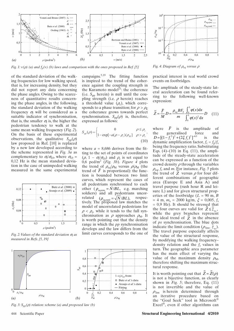
444 Scientific Paper Structural Engineering International 4/2010
of the standard deviation of the walk-ing frequencies for low walking speed, that is, for increasing density, but they did not report any data concerning the phase angles. Owing to the scarce-ness of quantitative results concern-ing the phase angles, in the following, the standard deviation of the walking frequency sf will be considered as a suitable indicator of synchronisation, that is, the smaller sf is, the higher the pedestrian tendency to walk at the same mean walking frequency (Fig. 2). On the basis of these experimental observations, the qualitative Spp(r) law proposed in Ref. [10] is replaced by a new law developed according to the scheme represented in Fig. 3a as complementary to sf/sf,0, where sf,0 = 0,12 Hz is the mean standard devia-tion in the case of unimpeded walking measured in the same experimental
campaigns.5,19 The fitting function is inspired to the trend of the coher-ence against the coupling strength in the Kuramoto model21: the coherence (i.e. Spp herein) is null until the cou-pling strength (i.e. r herein) reaches a threshold value (rc), which corre-sponds to a phase transition; for r > rc the coherance grows towards perfect synchronisation. Spp(r) is, therefore, expressed as follows:
cMc
cpp aS
])/(exp[10
)( ,
(10)
where a = 8,686 derives from the fit-ting to the set of points of coordinates (r, 1 − sf/sf,0) and rc is set equal to 0,6 ped/m2 (Fig. 3b). Figure 4 plots the trend of req/rM versus r/rM (the trend of F is proportional): the func-tion is bounded between two limit curves, which represent the cases of all pedestrians synchronised to each other ( ρeq,sync /= N BL, e.g. marching soldiers) and all pedestrians uncor-related ( ),ρeq,rand /= N BL respec-tively. The proposed law matches the model of uncorrelated pedestrians for r < rc, while it tends to the full syn-chronisation as r approaches rM. It is worth pointing out that the density range in which the pp synchronisation develops and the law differs from the limit curves corresponds to the one of
practical interest in real world crowd events on footbridges.
The amplitude of the steady-state lat-eral acceleration can be found refer-ring to the following well-known expression:
��ZFM
DBF
m
x x
x xD
L
L= = ∫∫
ρ ϕ
ϕeq
d
d
0 0
2
0
( )
( ) (11)
where F is the amplitude ofthe generalised force and D f f= − + −[( ) ( ) ] .1 22 2 2 0 5
r rξ is the dynamic amplification factor, fr = fp/fs being the frequency ratio. Substituting Eqs. (4)–(10) in Eq. (11), the ampli-tude of the steady-state acceleration can be expressed as a function of the crowd density r through the variables req, fr and m. For instance, Fig. 5 plots the trend of ��Z versus r for four dif-ferent combinations of geographic area (Europe E and Asia A) and travel purpose (rush hour R and lei-sure L) and for given structural prop-erties of the footbridge (L = 90 m, B = 4 m, ms = 2000 kg/m, x = 0,005, fs = 0,9 Hz). It should be stressed that the four curves are valid for �� ��Z z≤
lim,
while the grey branches represent the ideal trend of ��Z in the absence of ps synchronisation. The blue dots indicate the limit condition (r lim, ��z
lim).
The travel purpose especially affects the value of the structural response, by modifying the walking frequency–density relation and the fr values in turn. The geographic area parameter has the main effect of varying the value of the maximum density rM, therefore shifting the maximum struc-tural response.
It is worth pointing out that �� ��Z Z= ( )ρ is not a bijective function, as clearly shown in Fig. 5; therefore, Eq. (11) is not invertible and the value of r lim is herein determined through an iterative procedure based on the “Goal Seek” tool in Microsoft® Excel®, even if other algorithms can
2
1,5
v (m
/s)
2fp
(Hz)
1
0,5
0
2
2,5
1,5
1
0,5
00
(a) (b)1 2 3
r (ped/m2)
4 5 6 0 0,5 1
v (m/s)
1,5 2 2,5
Venuti and Bruno (2007) - L
Bertram and Ruina (2001)Venuti et al. (2007)
Butz et al. (2008)Butz et al. (2008)
-C-R
-R
Butz et al. (2008)
Oeding (1963) - L-C
Fig. 1: v(r) (a) and fp(v) (b) laws and comparison with the ones proposed in Ref. [5]
0,12
0,08
sf (
Hz)
0,04
00 0,5 1 1,5 2
r (ped/m2)
Butz et al. (2008)Araujo et al. (2009)
Fig. 2: Values of the standard deviation sf as measured in Refs. [5, 19]
1
sf/sf,0
Spp
00
(a) (b)
rc/rMr/rM
r/rM
rc1 0
0
0,2
0,4
0,6
0,8
S pp
1
0,2 0,4 0,6 0,8
1−sf/sf,0 from:
Butz et al.’s dataAraujo et al.’s dataFitting
1
rM
Fig. 3: Spp(r) relation: scheme (a) and proposed law (b)
100
10−1
10−2
req
/rM
10−30 rc
rM r/rM
0,2 0,4 0,6 0,8 1
reqreq,sync
req,rand
Fig. 4: Diagram of req versus r
x015_cs2.indd 444x015_cs2.indd 444 10/28/10 1:22:23 PM10/28/10 1:22:23 PM
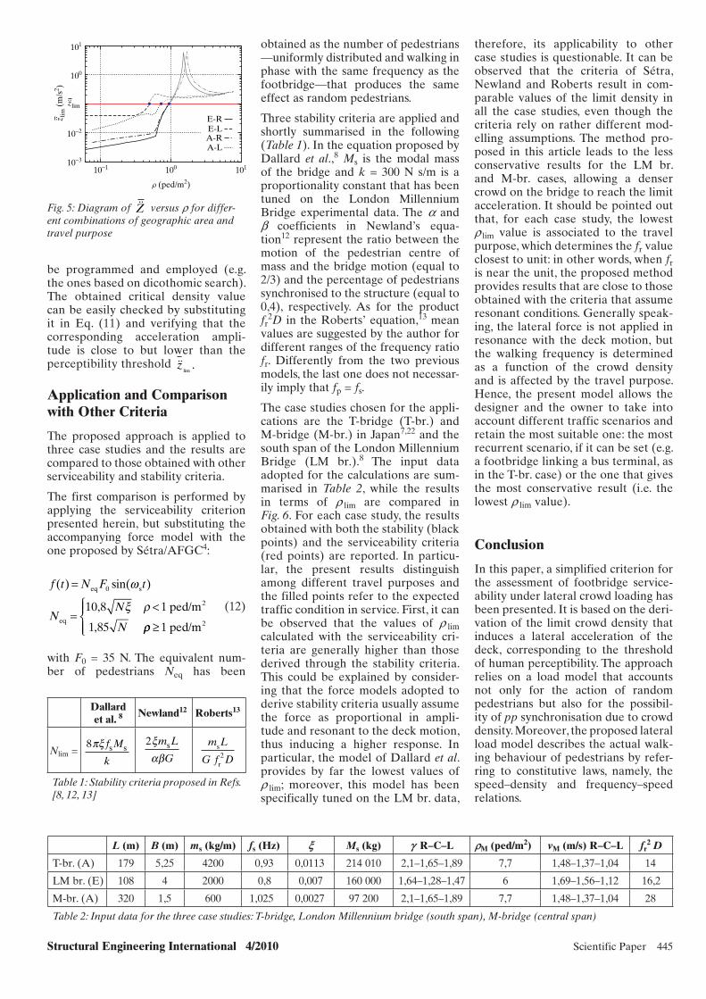
Structural Engineering International 4/2010 Scientific Paper 445
be programmed and employed (e.g. the ones based on dicothomic search). The obtained critical density value can be easily checked by substituting it in Eq. (11) and verifying that the corresponding acceleration ampli-tude is close to but lower than the perceptibility threshold ��z
lim.
Application and Comparison with Other Criteria
The proposed approach is applied to three case studies and the results are compared to those obtained with other serviceability and stability criteria.
The first comparison is performed by applying the serviceability criterion presented herein, but substituting the accompanying force model with the one proposed by Sétra/AFGC4:
f t N F t
NN
N
( ) sin( )=
=<
eq s
eq
2, ped/m
,
0
10 8 1
1 85
ω
ξ ρ
ρρ ≥
⎧⎨⎪
⎩⎪ 1 ped/m2
(12)
with F0 = 35 N. The equivalent num-ber of pedestrians Neq has been
obtained as the number of pedestrians —uniformly distributed and walking in phase with the same frequency as the footbridge—that produces the same effect as random pedestrians.
Three stability criteria are applied and shortly summarised in the following (Table 1). In the equation proposed by Dallard et al.,8 Ms is the modal mass of the bridge and k = 300 N s/m is a proportionality constant that has been tuned on the London Millennium Bridge experimental data. The a and b coefficients in Newland’s equa-tion12 represent the ratio between the motion of the pedestrian centre of mass and the bridge motion (equal to 2/3) and the percentage of pedestrians synchronised to the structure (equal to 0,4), respectively. As for the product fr
2D in the Roberts’ equation,13 mean values are suggested by the author for different ranges of the frequency ratio fr. Differently from the two previous models, the last one does not necessar-ily imply that fp = fs.
The case studies chosen for the appli-cations are the T-bridge (T-br.) and M-bridge (M-br.) in Japan7,22 and the south span of the London Millennium Bridge (LM br.).8 The input data adopted for the calculations are sum-marised in Table 2, while the results in terms of r lim are compared in Fig. 6. For each case study, the results obtained with both the stability (black points) and the serviceability criteria (red points) are reported. In particu-lar, the present results distinguish among different travel purposes and the filled points refer to the expected traffic condition in service. First, it can be observed that the values of r lim calculated with the serviceability cri-teria are generally higher than those derived through the stability criteria. This could be explained by consider-ing that the force models adopted to derive stability criteria usually assume the force as proportional in ampli-tude and resonant to the deck motion, thus inducing a higher response. In particular, the model of Dallard et al. provides by far the lowest values of r lim; moreover, this model has been specifically tuned on the LM br. data,
therefore, its applicability to other case studies is questionable. It can be observed that the criteria of Sétra, Newland and Roberts result in com-parable values of the limit density in all the case studies, even though the criteria rely on rather different mod-elling assumptions. The method pro-posed in this article leads to the less conservative results for the LM br. and M-br. cases, allowing a denser crowd on the bridge to reach the limit acceleration. It should be pointed out that, for each case study, the lowest r lim value is associated to the travel purpose, which determines the fr value closest to unit: in other words, when fr is near the unit, the proposed method provides results that are close to those obtained with the criteria that assume resonant conditions. Generally speak-ing, the lateral force is not applied in resonance with the deck motion, but the walking frequency is determined as a function of the crowd density and is affected by the travel purpose. Hence, the present model allows the designer and the owner to take into account different traffic scenarios and retain the most suitable one: the most recurrent scenario, if it can be set (e.g. a footbridge linking a bus terminal, as in the T-br. case) or the one that gives the most conservative result (i.e. the lowest r lim value).
Conclusion
In this paper, a simplified criterion for the assessment of footbridge service-ability under lateral crowd loading has been presented. It is based on the deri-vation of the limit crowd density that induces a lateral acceleration of the deck, corresponding to the threshold of human perceptibility. The approach relies on a load model that accounts not only for the action of random pedestrians but also for the possibil-ity of pp synchronisation due to crowd density. Moreover, the proposed lateral load model describes the actual walk-ing behaviour of pedestrians by refer-ring to constitutive laws, namely, the speed–density and frequency–speed relations.
Dallard et al. 8 Newland12 Roberts13
Nlim = 8πξ f M
ks s
2ξαβ
m L
Gs m L
G f Ds
r2
Table 1: Stability criteria proposed in Refs. [8, 12, 13]
L (m) B (m) ms (kg/m) fs (Hz) w Ms (kg) f R–C–L qM (ped/m2) vM (m/s) R–C–L fr2 D
T-br. (A) 179 5,25 4200 0,93 0,0113 214 010 2,1–1,65–1,89 7,7 1,48–1,37–1,04 14
LM br. (E) 108 4 2000 0,8 0,007 160 000 1,64–1,28–1,47 6 1,69–1,56–1,12 16,2
M-br. (A) 320 1,5 600 1,025 0,0027 97 200 2,1–1,65–1,89 7,7 1,48–1,37–1,04 28
Table 2: Input data for the three case studies: T-bridge, London Millennium bridge (south span), M-bridge (central span)
10−3
10−1 100
r (ped/m2)
101
E-RE-LA-RA-L
10−2
100
101
zlim..
z lim
(m
/s2 )
..
Fig. 5: Diagram of ��Z versus r for differ-ent combinations of geographic area and travel purpose
x015_cs2.indd 445x015_cs2.indd 445 10/28/10 1:22:24 PM10/28/10 1:22:24 PM
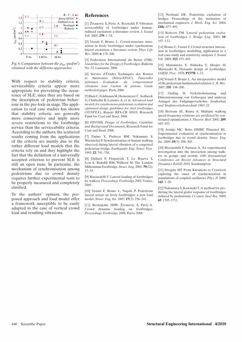
446 Scientific Paper Structural Engineering International 4/2010
Fig. 6: Comparison between the r lim (ped/m2) obtained with the different approaches
0T-br. LM br. M-br.
0,2
0,4
0,6
0,8
1,2
1,4 L
R
CL
C
R
L
R - C - LSétra/AFGCDallard et al.
NewlandRobertsC
R
rlim
(pe
d/m
2 ) 1
With respect to stability criteria, serviceability criteria appear more appropriate for preventing the occur-rence of SLE, since they are based on the description of pedestrian behav-iour in the pre-lock-in stage. The appli-cation to real case studies has shown that stability criteria are generally more conservative and imply more severe restrictions to the footbridge service than the serviceability criteria. According to the authors, the scattered results coming from the applications of the criteria are mainly due to the rather different load models that the criteria rely on and they highlight the fact that the definition of a universally accepted criterion to prevent SLE is still an open issue. In particular, the mechanism of synchronisation among pedestrians due to crowd density requires further experimental tests to be properly measured and completely clarified.
To the authors’ opinion, the pro-posed approach and load model offer a framework susceptible to be easily adapted in the case of vertical crowd load and resulting vibrations.
References
[1] Živanovic S, Pavic A, Reynolds P. Vibration serviceability of footbridges under human-induced excitation: a literature review. J. Sound Vib. 2005; 279: 1–74.
[2] Venuti F, Bruno L. Crowd-structure inter-action in lively footbridges under synchronous lateral excitation: a literature review, Phys. Life Rev. 2009; 6: 176–206.
[3] Federation International du Beton (FIB). Guidelines for the Design of Footbridges, Bulletin No. 32, Lausanne, 2006.
[4] Service d’Études Techniques des Routes et Autoroutes (Sétra/AFGC). Passerelles piétonnes – Evaluation du comportement vibratoire sous l’action de piétons. Guide méthodologique. Paris, 2006.
[5] Butz C, Feldmann M, Heinemeyer C, Sedlacek G, Chabrolin B, Lemaire A, et al. Advanced load models for synchronous pedestrian excitation and optimised design guidelines for steel footbridges (SYNPEX), Report RFS-CR 03019, Research Fund for Coal and Steel, 2008.
[6] HIVOSS, Design of Footbridges: Guideline and Background Documents, Research Fund for Coal and Steel, 2008.
[7] Fujino Y, Pacheco BM, Nakamura S, Warnitchai P. Synchronisation of human walking observed during lateral vibration of a congested pedestrian bridge. Earthquake Eng. Struct. Dyn. 1993; 22: 741–758.
[8] Dallard P, Fitzpatrick T, Le Bourva S, Low A, Ridsdill RM, Willford M. The London Millennium Footbridge. Struct. Eng. 2001; 79(22): 17–33.
[9] Ricciardelli F. Lateral loading of footbridges by walkers. Proceedings Footbridge 2005, Venice, 2005.
[10] Venuti F, Bruno L, Napoli P. Pedestrian lateral action on lively footbridges: a new load model. Struct. Eng. Int. 2007; 17(3): 236–241.
[11] Brownjohn JMW, Živanovic S, Pavic A. Crowd dynamic loading on footbridges. Proceedings Footbridge 2008, Porto, 2008.
[12] Newland DE. Pedestrian excitation of bridges. Proceedings of the institution of mechanical engineers. J. Mech. Eng. Sci. 2004; 218c: 477–492.
[13] Roberts TM. Lateral pedestrian excita-tion of footbridges. J. Bridge Eng. 2005; 10: 107–112.
[14] Bruno L, Venuti F. Crowd-structure interac-tion in footbridges: modelling, application to a real case-study and sensitivity analyses. J. Sound Vib. 2009; 323: 475–493.
[15] Matsumoto Y, Nishioka T, Shiojiri H, Matsuzaki K. Dynamic design of footbridges. IABSE Proc. 1978; P17/78: 1–15.
[16] Venuti F, Bruno L. An interpretative model of the pedestrian fundamental relation. C. R. Mec. 2007; 335: 194–200.
[17] Oeding D. Verkehrsbelastung und Dimensionierung von Gehwegen und anderen Anlagen des Fußgängerverkehrs. Straßenbau und Straßenverkehrstechnik 1963; 22.
[18] Bertram JE, Ruina A. Multiple walking speed-frequency relations are predicted by con-strained optimization. J. Theoret. Biol. 2001; 209: 445–453.
[19] Araújo MC, Brito HMBF, Pimentel RL. Experimental evaluation of synchronisation in footbridges due to crowd density. Struct. Eng. Int. 2009; 19(3): 298–303.
[20] Ricciardelli F, Pansera A. An experimental investigation into the interaction among walk-ers in groups and crowds. 10th International Conference on Recent Advances in Structural Dynamics RASD 2010, Southampton.
[21] Strogatz SH. From Kuramoto to Crawford: exploring the onset of synchronization in populations of coupled oscillators. Phys. D 2000; 143: 1–20.
[22] Nakamura S, Kawasaki T. A method for pre-dicting the lateral girder response of footbridges induced by pedestrians. J Constr. Steel Res. 2009; 65: 1705–1711.
x015_cs2.indd 446x015_cs2.indd 446 10/28/10 1:22:24 PM10/28/10 1:22:24 PM

Structural Engineering International 4/2010 Technical Report 447
The Construction of the Main Bridge of the Yichang Yangtze River Railway Bridge in ChinaYiqiao Zhou, Civil Eng.; Lichao Zhang, Civil Eng.; China Railway Major Bridge Engineering Co. Ltd., Wuhan, China.
Contact: [email protected]
first use of this kind of structure for a railway bridge in the world but also, with a main span length of 275 m, the bridge ranks among the longest of its type in the world at present.
General Description
This bridge across the Yangtze River at Yichang City is a vital link between the newly constructed railway line in Yichang, Hubei Province and the city of Wanzhou in the Chongqing munici-pality. The span arrangement of whole bridge from the southern to the north-ern bank is 10 × 49,2 m simply sup-ported PC box girders + (130 + 2 × 275 + 130 m) continuous PC rigid-frame girder with concrete-filled steel tube flexible arch + 14 × 48,2 m simply sup-ported PC box girder + (56 + 108 + 56 m) continuous PC girder + 9 × 32 m simply supported PC beam; the total length is 2526,73 m. A three-direc-tional pre-stress system and C60 high-performance concrete was adopted for the PC girder of the main bridge. The structure of arch rib is a parallel concrete-filled steel tube truss and the arch axis is a quadratic parabola. The calculated span of the arch is 264 m and the arch rise is 52,8 m. The rise–span ratio is 1/5,0. C50 grade micro-expansion concrete has been filled in the rib tube, and the suspenders that connect the arch rib and PC girder are parallel steel strands (Fig. 1).
Construction of Substructure
The foundation of the main bridge comprises reinforced bored piles; all
the pile tips were embedded into the solid bedrock beneath the riverbed. There are 12 piles (each of diameter Φ 3,0 m) for each of the three main piers and 9 piles (Φ 2,0 m) for each of the two side piers. The pile caps are 17,0 m × 23,0 m × 5,0 m rectangular reinforced concrete structures with rounded corners in cross section. A rectangular single-cell reinforced con-crete pier shaft of cross section 8,0 m × 12,0 m has been used for Pier 12, and a twin-wall reinforced concrete pier shaft of cross section 3,0 × 12,0 m, with 5,0 m central spacing between walls is adopted for Piers 11 and 13. The height of main pier shaft is 38,5 m. Each of the two side piers (Piers 10 and 14) has a solid rectangular shaft with cut-cornered cross section and a tray-type pier cap.
Piling works were carried out from the working platform over water by a boring machine using the air-lifting reversed-circulation method. When all the piles of a pier had been con-structed, a steel cofferdam was sunk to the designed depth. Construction of the pile cap and the lower section of pier shaft commenced after the bot-tom was sealed by tremie concrete and the water was pumped out of the cof-ferdam. The remaining sections of the pier shaft were constructed by means of a climbing formwork.
Construction of PC Rigid-Frame Girder
The superstructure of the main bridge is a single-box double-cell PC girder
Abstract
Railway construction technology in China, especially of high-speed railway long-span bridge construction, has been developing rapidly since the beginning of the twenty-first century. To main-tain the dynamic characteristics, travel safety and passenger comfort when the train travels over a bridge at high speed, and, at the same time, to meet the requirement of economical and technical viability of construction of the bridge—was a challenging problem. For solving this problem, many new types of bridge structure have been devel-oped for railway and high-speed rail-way long-span bridges. The arch beam hybrid structure is one of the structures that have been widely used in China. It is normally made up of a prestressed concrete (PC) beam, a rigid frame, or V-shaped piers and a steel arch or con-crete-filled steel tube arch.
Keywords: hybrid structure; long-span PC rigid frame; concrete-filled steel tube flexible arch; arch rib rotate– lifting synchronously; railway bridge.
Introduction
Recently, a long-span arch beam hybrid bridge structure has been successfully used in constructing the main structure of the Yichang Yangtze River Railway Bridge, which combined the PC rigid-frame girder with a concrete-filled steel tube flexible arch. The bridge carries double rail lines designed to support a train velocity of 160 km/h. The span arrangement of the main bridge is 130 + 2 × 275 + 130 m. This is not only the
Fig. 1: Elevation for the main bridge (Units: m)
130,8
Yichang
275,0 275,0 130,8
Wanzhou
44,0
14,5
38,5
14,5
38,5
14,5
38,530
,04,
037
,0 5,0
26,0
5,0
45,0
5,0
40,0
4,0
34,0
9φ2,0 m bored piles12φ3,0 m bored piles
12φ3,0 m bored piles12φ3,0 m bored piles
11
9φ1,5 m bored piles
10
12
1413
x090.indd 447x090.indd 447 28/10/10 8:50 AM28/10/10 8:50 AM
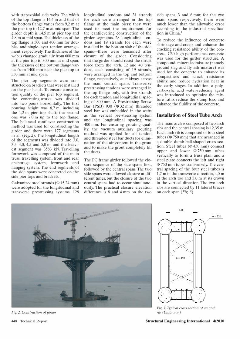
448 Technical Report Structural Engineering International 4/2010
with trapezoidal side webs. The width of the top flange is 14,4 m and that of the bottom flange varies from 9,2 m at the pier top to 12,7 m at mid span. The girder depth is 14,5 m at pier top and 4,8 m at mid span. The thickness of the top flange is 500 and 400 mm for dou-ble- and single-layer tendon arrange-ment, respectively. The thickness of the web is changed gradually from 600 mm at the pier top to 300 mm at mid span; the thickness of the bottom flange var-ies from 1400 mm near the pier top to 350 mm at mid span.
The pier top segments were con-structed on brackets that were installed on the pier heads. To ensure construc-tion quality of the pier top segment, the concreting-works was divided into two pours horizontally. The first pouring height was 8,7 m, including the 1,2 m pier top shaft; the second one was 7,0 m up to the top flange. The balanced cantilever construction method was used for constructing the girder and there were 177 segments in all (Fig. 2). The longitudinal length of the segments was divided into 3,0, 3,5, 4,0, 4,5 and 5,0 m, and the heavi-est segment was 3583 kN. Travelling formwork was composed of the main truss, travelling system, front and rear anchorage system, formwork and hanging system. The end segments of the side spans were concreted on the side pier tops and brackets.
Galvanized steel strands (Φ 15,24 mm) were adopted for the longitudinal and transverse prestressing systems. 128
longitudinal tendons and 31 strands for each were arranged in the top flange at the main piers; they were used to meet the requirement for the cantilevering construction of the girder segments. 28 longitudinal ten-dons and 19 strands for each were installed in the bottom slab of the side spans—these were tensioned after closure of the girder. Considering that the girder should resist the thrust force from the arch, 12 and 40 ten-dons, each consisting of 19 strands, were arranged in the top and bottom flange, respectively, at midway across the main central spans. Transverse prestressing tendons were arranged in the top flange only, with five strands for each tendon and longitudinal spac-ing of 800 mm. A Prestressing Screw Bar (PSB) 930 (Φ 32 mm) threaded steel bar was embedded in the webs as the vertical pre-stressing system and the longitudinal spacing was 400 mm. For ensuring grouting qual-ity, the vacuum auxiliary grouting method was applied for all tendon and threaded steel bar ducts for elimi-nation of the air content in the grout and to make the grout completely fill the ducts.
The PC frame girder followed the clo-sure sequence of the side spans first, followed by the central spans. The two side spans were allowed closure at dif-ferent times, but the closure of the two central spans had to occur simultane-ously. The practical closure elevation difference is 8 and 4 mm on the two
side spans, 3 and 6 mm; for the two main spans respectively, these were much lower than the allowable error according to the industrial specifica-tion in China.1
To reduce the influence of concrete shrinkage and creep, and enhance the cracking resistance ability of the con-crete, C60 high-performance concrete was used for the girder structure. A compound–mineral admixture (namely ground slag and fly ash mixture) was used for the concrete to enhance its compactness and crack resistance ability, and reduce hydration heat in the early stages. In addition, a poly-carboxylic acid water-reducing agent was introduced to optimize the mix-ture ratio, reduce the slump loss, and enhance the fluidity of the concrete.
Installation of Steel Tube Arch
The main arch is composed of two arch ribs and the central spacing is 12,35 m. Each arch rib is composed of four steel tubes (Φ 750 mm) that are arranged in a double dumb-bell-shaped cross sec-tion. Steel tubes (Φ 450 mm) connect upper and lower Φ 750 mm tubes vertically to form a truss plan, and a steel plate connects the left and right Φ 750 mm tubes transversely. The cen-tral spacing of the four steel tubes is 1,7 m in the transverse direction, 4,0 m at the arch toe and 3,0 m at its crown in the vertical direction. The two arch ribs are connected by 11 lateral braces on each span (Fig. 3).
Fig. 2: Construction of girder
1700
φ = 750
φ = 450
Fig. 3: Typical cross section of an arch rib (Units: mm)
x090.indd 448x090.indd 448 28/10/10 8:50 AM28/10/10 8:50 AM
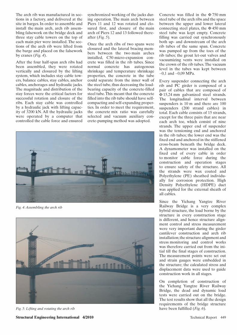
Structural Engineering International 4/2010 Technical Report 449
Concrete was filled in the Φ 750 mm steel tube of the arch ribs and the space between the upper and lower lateral connecting steel plates, the Φ 450 mm steel tube was kept empty. Concrete filling was carried out synchronously both up- and downstream of the arch rib tubes of the same span. Concrete was pumped up from the toes of the rib tubes; the grout let-out valves and vacuumizing vents were installed on the crown of the rib tubes. The vacuum level in the tubes was kept between −0,1 and −0,09 MPa.
Every suspender connecting the arch rib and PC girder is composed of a pair of cables that are composed of Φ 15,24 mm galvanized steel strands. The longitudinal interval between suspenders is 10 m and there are 100 suspenders (200 strand cables) in total. Each cable consists of 15 strands, except for the three pairs that are near each arch toe, which consist of nine strands. The upper end of suspender was the tensioning end and anchored in the rib tubes; the lower end was the fixed end and anchored in the stiffened cross-beam beneath the bridge deck. A dynamometer was installed on the fixed end of every cable in order to monitor cable force during the construction and operation stages to ensure safety of the structure. All the strands were wax coated and Polyethylene (PE) sheathed individu-ally for corrosion protection. High Density Polyethylene (HDPE) duct was applied for the external sheath of all cables.
Since the Yichang Yangtze River Railway Bridge is a very complex hybrid structure, the load borne by the structure in every construction stage is different, and hence structure align-ment control and stress measurement were very important during the girder cantilever construction and arch rib installation; the structure alignment and stress monitoring and control works was therefore carried out from the ini-tial till the final stages of construction. The measurement points were set out and strain gauges were embedded in the structure; the calculated stress and displacement data were used to guide construction work in all stages.
On completion of construction of the Yichang Yangtze River Railway Bridge, the dead and dynamic load tests were carried out on the bridge. The test results show that all the design requirements of the bridge structure have been fulfilled (Fig. 6).
The arch rib was manufactured in sec-tions in a factory, and delivered at the site in barges. In order to assemble and install the main arch, arch rib assem-bling falsework on the bridge deck and three stay cable towers on the top of each main pier were installed. The sec-tions of the arch rib were lifted from the barge and placed on the falsework by cranes (Fig. 4).
After the four half-span arch ribs had been assembled, they were rotated vertically and closured by the lifting system, which includes stay cable tow-ers, balance cables, stay cables, anchor cables, anchorages and hydraulic jacks. The magnitude and distribution of the stay forces were the critical factors for successful rotation and closure of the ribs. Each stay cable was controlled by a hydraulic jack with lifting capac-ity of 3200 kN. All the hydraulic jacks were operated by a computer that controlled the cable force and ensured
Fig. 4: Assembling the arch rib
Fig. 5: Lifting and rotating the arch rib
synchronized working of the jacks dur-ing operation. The main arch between Piers 11 and 12 was rotated and clo-sured first, and closure of the main arch of Piers 12 and 13 followed there-after (Fig. 5).
Once the arch ribs of two spans were closured and the lateral bracing mem-bers between the two main arches installed, C50 micro-expansion con-crete was filled in the rib tubes. Since normal concrete has autogenous shrinkage and temperature shrinkage properties, the concrete in the tube could separate from the inner wall of the steel tube, thus decreasing the load-bearing capacity of the concrete-filled steel tube. This meant that the concrete filled into the rib tube should have self-compacting and self-expanding proper-ties. In order to meet the requirement, the concrete mix ratio was carefully selected and vacuum auxiliary con-crete-pumping method was adopted.
x090.indd 449x090.indd 449 28/10/10 8:50 AM28/10/10 8:50 AM

450 Technical Report Structural Engineering International 4/2010
the arch and the girder. The whole structure thus has a graceful profile in addition to the excellent economic and technical viability.
References
[1] Code for Construction on Bridge and Calvert of Railway TB10203-2002, China Railway Publishing House, Clause 9.5.7, 87.
[2] Luo S, Yan A, Liu Z. The research of long span continuous rigid frame-flexible arch hybrid bridge structure. Journal of Railway Science and Engineering 2004; 2: 57–62.
Fig. 6: The completed Yichang Yangtze River Railway Bridge
Conclusion
The PC rigid-frame, concrete-filled, steel tube arch hybrid structure adopted for the Yichang Yangtze River Bridge is a new application for con-struction of a double-tracked railway bridge. The PC rigid frame girder and the concrete-filled steel tube arch bear the load together; the dead load of the girder is mainly borne by the rigid frame itself; the secondary load and live load are borne jointly by the girder and the arch. The magnitude of the forces resisted by the girder and arch depends, respectively, on the rigidity of
its individual structure and the area of the flexible suspenders.2 The mechani-cal behaviour of the structure to resist bending is made up of resistance of the arch to the compressive stress and that of the girder to the tension stress. The horizontal thrust of the arch is balanced by the axial tension in the girder. Since the structure has excellent stiffness and stability, most external loads could not cause a horizontal thrust on the pier As a result, the bending moment resisted by girder is decreased; so the section dimensions of the girder could be reduced accordingly, maximizing the advantages of force resistance of
SEI Data BlockSEI Data Block
Owner: Wuhan Railway Administration Bureau, Ministry of Railways, PRC
Designer: China Railway Siyuan Survey and Design Group Co. Ltd., PRC
Contractor: China Railway Major Bridge Engineering Group Co. Ltd., PRC
Steel (t): 25 167Concrete (m3): 13 672Total cost (USD million): 64,18
Service date: Expected by December 2010
x090.indd 450x090.indd 450 28/10/10 8:50 AM28/10/10 8:50 AM

Structural Engineering International 4/2010 Technical Report 451
Static and Dynamic Analysis of the “Piedra Movediza” Replica Rock, ArgentinaMaría Inés Montanaro; Civil Eng., Maria Haydee Peralta; Civil Eng., Norma Ercoli; Civil Eng., Maria Laura Godoy; Civil Eng., Irene Rivas; Prof., National University of the Centre of Buenos Aires Province, Civil Engineering, Buenos Aires,
Argentina. Contact: [email protected]
toppled on 29 February 1912. In May 2007, a replica was set up in the same place where the original rock stood.
Work Team
An agreement was signed between the Tandil Government and the Universidad Nacional del Centro de la Provincia de Buenos Aires (UNCPBA) to commence the studies that would embark on the project to create a rep-lica of the moving rock, a team was formed with teachers and a graduate of the Civil Engineering Department, coordinated by the engineer, and external participants. The engineer, and a team from the Universidad Nacional de La Plata, together with the Aeronautics Department and a geologist, also took part.
Plan of Action
A plan of action was established fol-lowing certain given guidelines:
– The replica should have the same geometrical dimensions as the origi-nal rock.
– It should be fi xed in the same posi-tion as the original rock.
– It should be situated at the same place on Cerro La Movediza.
– It should consist of a steel structure and it should be coated with a com-posite material capable of reproduc-ing the colour and texture of the original rock.
Activities
Topographic Studies
The planialtimetric topographic sur-veys determined the position and loca-tion of the replica. The geometry of the replica was determined from an analysis of the available information and from the survey of the geometry of the fallen rock that lies at the foot of the Cerro La Movediza. Infrared rays, laser electronic tachometres and GPS receiver systems were used to this end. 1523 points among the three exist-
ing pieces of rock were surveyed in a planialtimetric way. The study showed that the rock had an approximate vol-ume of 91 m3, an approximate weight of 248 tons and an external surface of approximately 133 m2.
Geological and Geotechnical Surveys
These studies included, on one hand, the evaluation of the hill disconti-nuities existing in the location. It was observed that the hill had a fissure, the geological and geotechnical character-istics of which were studied, leading to the conclusion that this did not, in any way, render the task of anchoring the replica to the hill impossible.
On the other hand, the characteristics of the rock base, which determined the depth of anchors and their size, were studied. It was reported that the solid rock on the hill had a granite struc-ture and that it presented very good geological characteristics2 ideal for anchoring the replica.
Wind Tunnel Study
This study allowed the assessment of the impact of the topography on the location and the geometry of the structure in the distribution of the wind pressure. The static and dynamic forces at the anchoring for each direc-tion of the wind were also measured. The range of standard frequencies where higher levels of non-stationary aerodynamic load can be found was also determined.
A 1 : 40 scale prototype model of the replica of the “Piedra Movediza” and part of the summit of Cerro La Movediza were tested in the wind tun-nel of the Aeronautics Department at the Faculty of Engineering at the UNLP. The model of the hill sum-mit was modified to allow its rota-tion in the tunnel test section and to study the winds in eight directions (S, SW, W, NW, N, NE, E and SE). The S directions (direction of more frequent winds) – SW (direction of winds of higher intensity) and SE – follow the
Abstract
This paper describes the activities involved in the development of the proj-ect “Piedra Movediza” Replica, located on the La Movediza hill in the city of Tandil, Argentina, in May, 2007. The nature of the project warranted multi-disciplinary works involving topogra-phers, geologists and private enterprises for the design and realisation of the covering material, construction of the anchors, hoisting and the subsequent assembly. Attention was especially given to the structural aspect, for which a typology consisting of an internal steel structure formed by a framework consisting of four grids arranged in two orthogonal planes was adopted. These grid beams transferred the load to the grid column or mast with its vertical axis coinciding with the vertical axis of sup-port. The structure was complemented by cross, longitudinal and horizontal frames, which played a dual role: first, to copy the rock’s external geometry and serve as a mould for the outer cov-ering, and second, to comply with the resistance function of transmitting the external loads to the internal structure. A static and dynamic analysis of the resistant structure was performed.
Keywords: steel; composite; static and dynamic analysis.
History and Aim
Tandil has always been famous for the imposing Piedra Movediza, which used to rest at an inconceivably steep angle on one of the hilltops of the city. This rock finally smashed on the valley floor on 29 February 1912. The place where this rock once stood is one of the most visited places in Tandil.
The Piedra Movediza (or “moving stone”), a large boulder, stood seem-ingly miraculously balanced on the brink of a chasm. To demonstrate the slight movements of the boulder, it was common practice to place bottles or some other things on its base to see them break.1 The moving stone
x079.indd 451x079.indd 451 10/26/10 2:11 AM10/26/10 2:11 AM

452 Technical Report Structural Engineering International 4/2010
original geometry. On the basis of the observations at the location, it was estimated that the changes in the mod-elling of the hill were conservative, as they may induce higher wind loads in the test than those obtained in reality. Figure 1 shows an image of the tested model and the equipment used.
For each wind direction, forces and distribution of pressure at different speeds were measured to verify the independence of the Reynolds number of dimensionless coefficients of force and pressure.
The distribution of pressure in the rep-lica model for the eight wind directions was measured in 56 nodes by means of sensors, presenting the information as a dimensionless coefficient of pressure Cp. Analysis of the specified pressure coefficients reveals the strong influ-ence of the irregular geometry and the topography (at location) in their distri-bution. The data reported by the tests allowed the corresponding calibration of the numerical models used and the comparison of results.
Covering Material
The covering material has a structural function, necessitating that certain requirements of strength, stiffness and durability be followed. Because of the nature of the project, the covering material should simulate the texture and colour of the original rock and achieve an optimum weight to facili-tate the replica hoisting.
From the resistance point of view, the replica should resist the pressure of the wind and transmit it to its internal resistant structure.
In response to the request for simu-lating the texture and colour of the original rock, a large amount of previ-ous works carried out with composite materials in this regard were referred to. Additionally, from a construction and assembly point of view, these kinds of materials have advantages because
of their lower weight, and based on this, a composite material for the cov-ering was adopted.
Structural Project
The project was designed considering that the replica would have the same geometrical dimensions, same appear-ance, texture and colour. It would also be located in the same position and location on the hill with respect to the original rock. Data from the previously indicated stages of the study made the structural project possible.
Structural Typology
The typology adopted, as shown in Fig. 2, consists of an internal steel struc-ture built in a construction company and made of a framework consisting of four grids arranged in two orthogonal planes according to Fig. 3. These grids relieve in a column, with its vertical axis coinciding with that of the original rock. The structure is complemented by vertical and horizontal frames, made of stiffened steel plates, which play a dual role: first, copying the external geometry of the rock and serving as a mould for the outer covering, and sec-ond, transmitting the loads caused by the wind to the internal structure. The connection of the horizontal external frames with the grids is mainly through the beams at three planes of stiffness.
Structural Analysis
A software based on Finite Element Method, was used for the static and dynamic structural analysis.
Static Behaviour
In the first instance and for the purpose of making a pre-dimensional study3 of the structure elements, simplified anal-yses in orthogonal planes coincident with those of the main grids of the frame were performed. These analyses, apart from enabling the initial pre-dimensional study, allowed making the typologies of the framework grids consistent with the external shape and dimensions of the original rock.
Simplified load combination related to adopted models, and load hypotheses arising from the overlapping of the dead load (weight structure + weight of the covering) and wind were con-sidered. To this effect, a distributed covering weight of 3 tons and a wind pressure corresponding to a speed of 50 m/s equivalent to 180 km/h was considered. The distribution of the wind pressures was obtained from the coefficients of pressure obtained through the tests in the wind tunnel for the eight tested directions and for the highest speed corresponding to 50 m/s.
For the transverse grids, the overload corresponding to the north wind as the worst combination was considered.
Following the pre-dimensional analysis of plane models, spatial static analyses were conducted considering nine load hypothesis corresponding to the dead loads and the combination of the eight states of independent wind loads with the dead load. The worst results for the central column corresponded with the column base plate.
Dynamic Behaviour
The unique characteristics of the struc-ture were obtained by dynamic analysis for purposes of comparison with inputs from wind tunnel tests, with reference to the standard frequency range in which the highest level of energy from non-stationary aerodynamic loads is concentrated. The reported range of normalised frequencies corresponds to a 1,7 and 6,5 Hz dynamic load Fig. 2: Structural typology
Fig. 1: Prototype model in wind tunnel Fig. 3: Frameworks
x079.indd 452x079.indd 452 10/26/10 2:11 AM10/26/10 2:11 AM

Structural Engineering International 4/2010 Technical Report 453
university and community, making the society highly appreciative of the uni-versity’s social role.
References
[1] “La Piedra Viva” Elías El Hage, Pomy Levy. Alfredo Bossio. Artes Gráficas. 1° Ed. Mayo, 2007.
[2] Informe petrográfico geofísico de los estudios realizados sobre la Piedra Movediza de Tandil. Inédito. Secretaría de Minería. Buenos Aires, 1962.
[3] Reglamento Argentino de Estructuras de Acero para Edificios. CIRSOC 301, Buenos Aires, Julio, 2005.
frequency. The first dynamic analysis performed with the pre-dimensional study used in the static analyses yielded values of the fundamental frequency, which was in the range of the highest load energy measured in the wind tun-nel. This contributed to the stiffness of the column of the structure and other areas of importance that led to a fun-damental frequency of 8 Hz away from the range of excitement mentioned.
Design of the Foundation
The design of the foundation of the moving rock replica basically includes four structural anchors of 5 m length, embedded in the base rock held by a single anchor plate of 70 mm thick-ness, with stiffeners arranged orthogo-nally and inserted into the rock with a grout-type injection material between the rock and the plate to ensure proper adherence. Additionally, three vertical inserts 1,5 m deep and of construction nature were used.
To facilitate the union of the structure with the foundation, the central col-umn was welded to a 1200 × 1150 × 50 mm base plate. This base plate was bolted, after the hoisting, to an ISO 8,8 anchor plate with 20 bolts of 1 ½" ISO 8,8 displayed on the anchor plate for that purpose. The base plate had cor-responding holes that were perfectly aligned for the assembly.
Construction Process
The construction process was led by the Secretary of the Ministry of Public Works and Services for the city of Tandil. The structure was built in a construction company in Tandil.
Figures 4 and 5 show the column, the grids and part of the frames, and the arrangement of the cross frames and the base plate, respectively.
The outer covering was built in as specified, with some adjustments in the colour and texture.
The drilling for the anchoring was done under the supervision of a geolo-gist, taking appropriate precautions considering the particular site where the task had to be carried out. The final re-design for the arrangement of the anchors and the corresponding plate proved to be an arduous task. To this effect, a pattern of the dimensions of the anchor plate, which facilitated the re-arrangement in response to the require-ments of the geological survey with regard to the separation of the fissure
Fig. 4: Central column
Fig. 5: Framework construction
Fig. 6: The relocation of the replica
Fig. 7: The replica crowned on the hill
plane, was built. The anchors were built by a company that specialised in rock anchoring; they also set the inserts and injected the grout according to the specifications stated. The anchor plate was hoisted by a crane already installed at the foot of the hill for mounting of the replica. The anchor plate with its 20 bolts was fixed to the replica via the base plate with holes. Before the hoist-ing of the replica, a test of uprooting the anchors was done, with results that were within the established limits. The relocation of the replica, from the con-struction company to the foot of the hill, was accompanied by applauding and waving of flags by deeply touched people, which showed what the rock meant to them and to the city.
The construction process lasted for approximately 4 months. The replica successfully crowned the hill on 13 May 2007.
A huge crane of about 9 tons hoisted the replica (Figs. 6 and 7).
Conclusion
The notable geometry of the replica and the site characteristics of the loca-tion made this project a real challenge. The development of the project and its subsequent execution showed the importance of working together for a project, especially when different disci-plines are involved. It also made possi-ble the sharing of knowledge between
SEI Data BlockSEI Data Block
Owner: Municipalidad de Tandil (Argentina)Contractor: Metalúrgica Marcelo Fernandez
Designer: National University of the Centre of Buenos Aires Province
Steel (t): 7Composite (t): 3Estimated cost (EUR million): 0,2
Service Date: May 2007
x079.indd 453x079.indd 453 10/26/10 2:11 AM10/26/10 2:11 AM

454 Technical Report Structural Engineering International 4/2010
Footbridge Studenci over the Drava River in Maribor, SloveniaViktor Markelj, Structural Eng., Manager, PONTING d.o.o. Maribor; Lecturer, Faculty of Civil Engineering, University of Maribor,
Slovenia. Contact: [email protected]
existing supports were strengthened and the old superstructure was substi-tuted with a new one.
In spite of a relatively simple and clear structural system, the bridge is dis-tinctly recognizable due to the interac-tion of its walking surface and structure elevation. Because of the transparency of its truss structure and symmetry, it is neutral to both the environment and the river landscape. In addition to the attractive configuration, the original design made way for an attractive and economic method of construction.
History
The history of the old footbridge is full of character. It was constructed in the year 1885 with three simply supported truss girders and wooden supports in the riverbed. After the flood in 1903, the bridge was provided with interme-diate stone supports (Fig. 1). During World War II, it was destroyed twice and each time reconstructed by the army. In the year 1946, the bridge was swept away by floods; two years later, the superstructure was substituted by a new one—with two welded plated gird-ers (Fig. 2). After the completion of the hydro power plant in 1968, the water level increased by about 5 m. In 2007, a new superstructure was constructed according to the winning solution of
the design competition conducted in 2004.
Design of the New Footbridge
To minimize construction costs, it was necessary to reuse the existing sup-ports of the old footbridge, thus dic-tating the spans of 3 × 42 = 126 m, and, at the same time, it was neces-sary to increase the existing navigation clearance under the bridge from 3,0 to 3,6 m of clear opening. Beside common requirements such as safety, durability and economy, the city of Maribor also sought an attractive, unique bridge that would be in harmony with the environment and would prove appeal-ing to the town dwellers.
The selected solution was a triangu-lar steel truss as a primary longitu-dinal structure (spine) along which a secondary transversal structure was to be raised (ribs). As neither of the banks had sufficient height for the structure, the structure was raised upwards through the walking surface, thus being divided into two parts. With a gradual rise of the deck, the structure disappears under the floor, joining both walkways over the mid-dle of the river and providing a com-mon surface for an unimpeded view of all sides and a peaceful meeting place.
Abstract
The paper presents the design and construction of the new footbridge Studenci over the Drava River in Maribor. In 2004, the City of Maribor issued an open, anonymous national call for proposals for the reconstruc-tion of the old bridge. In spite of the fact that it was an existing bridge that was to be reconstructed, the new bridge appeared in a new, entirely dif-ferent, contemporary image.
The existing old bridge structure of two steel I-shaped girders with con-crete deck was replaced by a new, steel, transparent, space truss struc-ture, with a wooden deck and linear LED illumination. Only the supports from the old bridge were preserved and these also were reconstructed and strengthened.
The ‘structural solution’ as presented in this paper, received a Footbridge Award in 2008.
Keywords: footbridge; pedestrian bridge; reconstruction; design compe-tition; steel structure.
Introduction
The new footbridge over the Drava River in Maribor is in fact a recon-struction of the old bridge where the
Fig. 1: Footbridge Studenci from 1885 to 1946 Fig. 2: Footbridge Studenci from 1948 to 2007
x085.indd 454x085.indd 454 28/10/10 9:02 AM28/10/10 9:02 AM

Structural Engineering International 4/2010 Technical Report 455
Description of the Footbridge and the Structure
The footbridge axis is in a straight line, the longitudinal alignment is in a convex vertical rounding with R = 1045 m and with a maximal slope of 5%. In the middle of the foot-bridge, the deck width is 3,20 m and at either end it is split into two parts of 2,40 m each, divided by a visible main structure breaking through the deck (Fig. 3).
The variation of the structure and deck alignment was solved by dividing the structure into two systems supporting the deck:
– The spine—main steel structure is a centrally positioned triangular truss of a constant structural height and width. The geometry enabled a sim-ple production in a workshop: after assembling on site by welding, it was erected in place simply by incremen-tally launching it over the existing structure. The main steel structure is made of structural steel S355 and protected with anticorrosive coats in light grey.
– Ribs—secondary steel structure rises along the main structure and car-ries the walking surface. Erected by bolting after the erection of the main structure, it is protected by hot galvanizing.
– Wooden deck structure made of transversal boards from hard exotic wood of 42 mm thickness, with a sawtooth profi le on the top.
The main structure is a space steel truss, consisting of three longitudinal
Fig. 3: Longitudinal section and plan of the new footbridge (Units: m)
B = 3,200–5,800
1,760Cross bracket width
1,5001,
750
0,720–3,140
Main structure widthCross bracket width1,760
Secondary structurecross bracket
f298,5 mmd = 8–2 mm
f114,3 mmd = 8–20 mm
f298,5 mmd = 26–20 mm
Main structure attachmentplates (altering position)
Bri
dge
axis
Fig. 4: Cross section of the footbridge is of constant shape—changing only at the ends of the secondary structure
Longitudinal section / side view
136,5042,00
3
42,00
4
5,25
3,05
Supp
ort a
xis
4
Supp
ort a
xis
3
Supp
ort a
xis
2
Supp
ort a
xis
1
2
42,00
3,05
3,60
1
5,25Studenci
Taborsko nabrezje
Koblarjev zalivLent
Strma ulicaRuska cesta
Drava river
Plan / view
136,50
Drava river
42,00 42,00
3,20
5,25
5,80
42,005,25
Fig 5: Reconstruction of the old river piers with jet-grouting piles (Units: m)
New pier cap New bearing block
5,45
6,50
254,524
253,200
0,50
Micropilef25 cm, L = 15,0 m
Strengthened existing pier
Water level
New bearing blockNew pier cap
Micropilef25 cm, L = 15,0 m
Strengthened existing pier
min
. 7,0
00 m
Jet-
grou
ting
pile
s
1,57
1,75° 1,75°
3,50°
0,25
15,0
0
14,5
0
0,25
2,70
253,200
254,524
0,50
Pie
r ax
is
1,60
River bed
min
. 7,0
00 m
Jet-
grou
ting
pile
s
3,17 3,17
7,50°7,50°
7,50° 7,50°
0,250,250,25
15,0
014
,50
os b
rvi
x085.indd 455x085.indd 455 28/10/10 9:02 AM28/10/10 9:02 AM

456 Technical Report Structural Engineering International 4/2010
Original (glued) wooden section 240/80 mm
LED linear diodes (L = 2400 mm, e = 40 mm)
Polycarbonate protectedstrip d = 3 mm
240,0
80,0
30,0°
30,0°
30,0°30,0°
Fig 6: Footbridge lighting is concealed within the wooden top rail of the steel railing
pipes—one pipe for the upper chord and two for the bottom chord. The triangular cross section is of con-stant form; the change is only in the pipe thickness and the position of the accessory piece for bolting the sec-ondary structure (Fig. 4). The axial distance between the upper and bot-tom pipes is 1,75 m which gives a total structural height of 2,05 m; the axial distance between the lower flanges is 1,50 m. The longitudinal pipes are of diameter ϕ = 298,5 mm, wall thick-ness varies from 8 to 20 mm and for the diagonal and cross pipes, ϕ = 114,3 mm. The camber of the main structure is of a constant radius R = 4000 m, the upright connections between lay-ers are not vertical but radial, so that the element lengths and mutual angles are equal along the total bridge length, making the construction cheaper and simpler.
The old river piers were reinforced with six piles and the abutments—because of greater width—with nine piles. The total length of the jet-grout-ing piles is 15 m—8 m through the old pier structure and 7 m through the gravel base (Fig. 5). The tops of exist-ing piers have been adapted for the needs of the new structure.
Fig. 7: Main truss of new footbridge positioned over the old structure
Fig. 8: Dismantling of the old structure
x085.indd 456x085.indd 456 28/10/10 9:02 AM28/10/10 9:02 AM

Structural Engineering International 4/2010 Technical Report 457
Fig. 9: Some details of the new footbridge
Fig. 10: Reconstructed footbridge Studenci over the Drava River in Maribor
method of erection was possible. After erection, the new structure was sup-ported by the remainder of the existing structure. Truss elements were erected above the intermediate supports and the bearings were grouted. Then the old footbridge was dismantled (Fig. 8). Some details of the new footbridge are shown in Fig. 9. The profile of the reconstructed footbridge Studenci can be seen in Fig. 10.
Conclusion
Since the city of Maribor could not give up more than 120 years old pedestrian route, it decided to recon-struct the old destroyed footbridge - on the existing supports, but with the new superstructure. The original design of the bridge’s reconstruction provides an attractive form and at the same time enables a very cost-effective way of building. The design solution has been presented with the Footbridge Award 2008 in the cat-egory of Technical medium span, with the judges declaring it as »A pleasing technical solution to a difficult set of criteria« and noticing its »Interesting new technical ideas«.
SEI Data BlockEI Data Block
Owner: City of MARIBOR, Slovenia
Structural design:PONTING d.o.o., Mari bor, Slovenia
Contractors:SGP Pomgrad GNG d.o.o., SloveniaSteel structure: Meteorit d.o.o., Slovenia
Bridge type: Steel space truss
Bridge size: Length: 130 m, Width: 3,2–5,8 m
Deck: Bangkirai wood: A = 550 m2
Steel S355: 93 000 kg
Lighting: LED 350W
Total cost (EUR million): 1,2
Service date: December 2007
The secondary structure, support-ing the wooden deck structure, is composed of transverse cantilever girders and longitudinal girders and is screwed to the main structure all along. The transverse cantilevers are at the same time railing balus-ters and are equal along the entire bridge length. The deck is made of transversely placed bangkirai wooden boards. The discreet lighting from the handrail is another special feature of the footbridge. The installed lighting power of LED diodes is only 350 W (Fig. 6).
Construction
The footbridge construction was inno-vative and was built at a low cost, as it used the existing structure as a support for erection. The structure was divided into two parts, the main longitudinal one and the secondary transverse one. The main structure is a triangular truss that was welded by segments and pro-gressively positioned over the exist-ing structure (Fig. 7). The separation into main and secondary structures reduced the transverse size of the structure to such an extent that this
x085.indd 457x085.indd 457 28/10/10 9:02 AM28/10/10 9:02 AM

458 Technical Report Structural Engineering International 4/2010
Sanchaji Bridge: Three-Span Self-Anchored Suspension Bridge, ChinaGonglian Dai, Prof., Dr, Civil Eng.; Xuming Song, Lecturer, Dr, Civil Eng.; Nan Hu, Graduate Student; Central South University,
Changsha, China. Contact: [email protected]
a (5 × 65 m) PSC continuous beam. Before project bidding, there were five bridges across Xiangjiang River in Changsha, including two arch bridges, two beam bridges and a cable-stayed bridge. The self-anchored suspension bridge system was selected because of its logical structural principles and the aesthetic value addition to the landscape1.
Geological Condition
The Sanchaji Bridge is located on a qua-ternary stratum, which mainly contains soil in the upper and slate in the lower levels. There are not many ups and downs at the surface of the river bed, where the main ingredients are sandy slate and metamorphic sandstones. The uniaxial compressive strength is 20,9 to 65,60 MPa. Rock forms the fourth level. The arrangement of the main span and the geological condi-tions are shown in Fig. 2. It can be seen that piers 11 and 12 that formed the foundation for the two towers adopted drilled pile groups of C30 class con-crete with length between 16 and 24 m. The C30 concrete pile cap under each tower is a dumbbell-shaped structure
including two caps with diameter of 17 m and thickness of 5 m linked by 7 × 4 m tie beam. Under each tower, there are 18 piles with a diameter of 2,4 m. The width of the channel located in the west of the island is about 700 m and its greatest depth is at about 6,0 m. Flood peak of Xiangjiang River frequently appears from late April to June, which covers about 86% of total number of peaks occurring in 1 year. The basin is so large that the flooding is quite heavy.
Design Criteria
The main design criteria for Sanchaji Bridge are high-way-I with design speed of 60 km/h; three-lane traffic loading in each direction with pedes-trian load of 4 kN/m; deck width of 35 m; lateral slope of bridge deck is 2,0% in two directions; longitudinal slope of bridge is 1,5%; temperature: design normal temperature is 20°C with muta-tive range of 0 to 40°C; normal design wind speed refers to average speed of 25,9 m/s; designed to withstand upto 7 grade intensity of magnitude for earth-quake; anti-collision standard refers to third-level fairways with 400 kN
Abstract
Sanchaji Bridge across the Xiangjiang River is located at the northern sec-tion of the Second Ring Road Project in Changsha, Hunan Province, China. Its main span is the longest in the world among all self-anchored suspen-sion bridges constructed using double towers and double cables till now. For a self-anchored bridge, structural behaviour and construction methods are totally different from those of a traditional suspension bridge. A main cable containing 37 prefabricated strands and streamlined steel box cross section was used as stiffened girder with a height of 3,6 m. A fully welded anchoring chamber was adopted to connect the main cable with the stiff-ened girder for the first time. The main tower is of reinforced concrete with a variable hollow box section. As for the construction method, launching meth-ods were selected for the erection of steel box girder and “non-stress” method for installation of hangers. The construction of the bridge was started on 10 September 2004 and completed on 1 September 2006. The completion of the bridge effectively relieved the traffic pressure in the northern region of Changsha and played a vital role in improving local economy. This paper introduces several features of the Sanchaji Bridge, including type selec-tion, structural behaviour and con-struction methods.
Keywords: self-anchored suspen-sion bridge; structural system; design parameters; construction method.
Introduction
Sanchaji Bridge shown in Fig. 1 is located at downstream Xiangjiang River in the northern region of Changsha, where the width between river banks is about 1442 m. The total length of the main bridge is 1577 m, with span arrangement of the whole bridge containing a (8 × 65 m) pre-stressed concrete (PSC) continuous beam, a (70 + 132 + 328 + 132 + 70 m) self-anchored suspension bridge and Fig. 1: The close view main span of Sanchaji Bridge
x082.indd 458x082.indd 458 28/10/10 9:17 AM28/10/10 9:17 AM

Structural Engineering International 4/2010 Technical Report 459
with a spacing of 600 mm. The thick-ness of the inclined web flange is 8 mm with longitudinal closed rib stiffeners at 400 mm spacing.
Main Tower and Pier
The main tower adopted a C50 class RC structure with variable cross sec-tions, as shown in Fig. 4. The height of the tower is 106,16 m in #11 and 104,453 m in #12 piers (from the top of pile cap). Above the bridge deck, the height is about 71,752 m. The cross section of the tower is of a hollow box type with dimensions of 5 (along the bridge) × 3,5 m (along the section) at the top. The column width along the direction of the bridge expands from the top to bottom according to the ratio 1 : 100. The two columns of the tower are linked by crossbeams with a spacing of 25 m at the top. There are two PSC crossbeams between columns with a hollow rectangular cross sec-tion. The crossbeam below the deck is 4,0 × 6,0 m in cross section and 0,6 m thick, equipped with 48,12-ϕj15,24 strands. As for the upper crossbeam, the dimensions are 3,0 × 4,5 m, with a thickness of 0,5 m, equipped with eight 12-ϕj15,24 strands. The thick-ness of the column is variable, being 700 mm above the lower crossbeams and 1 m below the same. Furthermore, all the joint parts between crossbeams and columns are strengthened, with a gradual variation in thickness. Because of saddle installation, the solid column area was adopted with a length of 4 m.
dampers were installed between the stiffened girder and tower columns at both towers, where each damper required a force of 100 tons. Therefore, the stiffened girder would be a float-ing system along the bridge under some slow loads, such as temperature variation, while the girder would be controlled by dampers at columns of the tower and reduce the force on the foundation of the tower during spe-cial live loads, such as vehicle braking force and earthquakes.
Stiffened Girder
In a self-anchored system, the stiffened girder will be under a great axial force. Therefore, the cross section of girder adopted a streamlined steel box type with Q345d steel, after the wind tun-nel test, as shown in Fig. 3. The main dimensions of the steel box girder cross section were as follows: the clear height of the box girder at the bridge axis was 3,60 m and overall width was 35 m. So, the high-span ratio of the box girder is 1 : 91,1 and high-width ratio is 1 : 9,72. The bridge deck adopted an orthotropic plate with a thickness of 12 to 14 mm at the top plate, 12 to 16 mm thickness at the web plate and 10 mm at the bottom plate, except at some local section near the tower. There is a diaphragm every 3 m with a thickness of 10 mm at normal sec-tion and 16 mm at the position of bearing. The U-shaped closed rib deck stiffeners are 260 mm deep and 8 mm thick with a spacing of 600 mm. At the bottom flange, the dimensions are 190 mm (depth) and 6 mm (thickness)
in longitudinal and 550 kN in lateral direction; channel clearance is 10 m while flood level is 36,78 m.
Structural System
Since no bridge of a similar type was constructed ever before, 1 : 28 over-all model test and 1 : 5 steel anchor-ing chamber test were carried out to verify the accuracy of finite element analyses. Test results were used in con-ceptual design and the details of the design of the bridge are as follows: (a) a five-span continuous girder was used in a self-anchored suspension bridge for the first time, which elimi-nated tremendous uplift force created by the anchorage of main cable at #10 and #13 piers. In this way, a negative reaction force at the bearings could be basically avoided under the dead load, and very little rotation at the beam end occurred during the ser-vice period; (b) the issue of stability is vital in this bridge because the cable is anchored at the girder of the suspen-sion bridge. So, it was addressed by placing precast concrete blocks in the box girder near the section of the pier where the heaviest weight was 8000 kg at #10 and #13 piers and 6000 kg at #11 and #12 piers. In this way, there was no negative reaction force at the bearings of these four piers mentioned under both dead load and live load, and the safety coefficient was maintained above 1,3; (c) the selection of restraint type would have a huge impact on structural behaviour. On the basis of analysis and comparison, four MSTU
35 000/211 400
13 8073693
2070
1200
3600
1000 2900 2200
Fig. 3: The semi cross section of the bridge after the wind tunnel test (Units: mm)Fig. 4: The main tower above the bridge deck
K41 + 504,35 K42 + 236,35732
11 + 34 × 9 + 11 = 32812 + 12 × 9 + 12 = 132 12 + 12 × 9 + 12 = 132 70
55,77056,720
25,202
57,964
129,655
58,515
129,655
57,964
23,496
56,720
9 10 11 12 13 14
55,770
70
Fig. 2: The main span arrangement of Sanchaji Bridge (Units: m)
x082.indd 459x082.indd 459 28/10/10 9:17 AM28/10/10 9:17 AM

460 Technical Report Structural Engineering International 4/2010
ers; deck system pavement. The major difficulties during the construction included four aspects as follows: (a) Incremental launching of the steel box girder. The launching platform was set between #9 and #10 piers where the water was deep and four tempo-rary piers were placed for carrying the main girder at middle span. The standard prefabricated segments were divided into two types (12 and 9 m) and assembled in site by welding. The weight of standard segment was 195,8 t of 12 m and 152,6 t of 9 m. According to the requirement of waterway dur-ing the construction, temporary piers were placed with a maximum span of 77 m, and the length of launching nose was 48 m. (b) The line shape control of the main girder and cable. Since the main girder was on a vertical curve with 24402,745 m radius, the segments were installed on the platform accord-ing to the line shape of the bridge girder and pre-camber consideration. Owing to a larger rise–span ratio, there was a huge difference in line shape before and after the installation of hangers. So, the installation of main cables should follow strict limits and enable the controlling plate to adjust the errors during cable fabrication. (c) “Non-stress” method in installation of hangers. To install the “non-stress” hangers, the girder was lifted by four temporary piers (740 mm raised in two piers near the tower and 1,48 m in piers of middle span), as shown in Fig. 6. After the installation of the hangers was completed, the temporary piers were removed and the girder system could find its final position,
ing chamber is superior to the con-crete one because cracking caused by huge local compressive stress could be avoided. Two hanger ropes were installed at each cable band, as shown in Fig. 5. Except for the two pairs of rigid hangers near the #10 and #13 piers, all hanger ropes were made of 85j5,1 mm galvanised steel wire. The prefabricated parallel wire strand hanger was pinned by a socket with cable and anchored at the girder. There are 122 pairs of hangers in the whole bridge with a spacing of 9 m. Screws with bolts were used for the connec-tions between the hanger and girder, so that the flow of force would be clear and installation easy. The hanger clamp is a symmetrical steel casting component and the length of the clamp is controlled by declining cable force and clamp traction force. On the basis of an experiment on hanger clamp, the traction force is maintained at 12 MPa instead of the regular 10 MPa to avoid the huge length of clamp. There are four saddles in the whole bridge with the self-balancing system so that blocks at the top of the tower are not needed. The major material of saddle is cast GZ25 with a weight of 40,5 t, including the upper component, lower plate, filled panel and so on.
Construction Method
The whole construction period was divided into five stages: founda-tion and tower erection; incremental launching of stiffened girder; erection of main cable; installation of hang-
Lightning protection devices were set up at the top of the column. Except for the two main towers, the remaining piers for approach are of twin-column type with a diameter of 3 m.
Cable System
On account of the larger rise–span ratio than that of the gravity-anchored suspension bridge or single tower one, it is vital to take into consideration the selection of hanger clamps, shape of cable design, installation method of hanger, and so on. The rise–span ratio of Sanchaji Bridge is 1/5 at mid-span and 1/10,6245 at side span2. 37 parallel wire strands, comprised of 127 j5,1 mm high-strength galvanised steel wires, formed one main cable, which was installed by Prefabricated Parallel Wire Strands (PPWS) method. The total length of the main cable was 680,70 m with a spacing of 25,0 m between the wires. The amount of steel in the main cable was about 1026 t. The shape of the main cable was catenary at every construction stage before operation, because the shape between two tower saddles was just caused by the dead load along the cable. The material adopted for strand anchor tube and cover plate was ZG310-570 and Q235-A, while the filled mate-rial in tube was zinc–copper alloy. The fully welded anchoring chamber was adopted for connecting the main cable with the stiffened girder because the height of girder was not required to increase in order to ensure supe-rior appearance and convenient con-struction of the girder. Moreover, the structural behaviour of this anchor-
Fig. 5: The hanger rope between main cable and stiffened girder Fig. 6: Sanchaji Bridge after the installation of hanger (during construction)
x082.indd 460x082.indd 460 28/10/10 9:17 AM28/10/10 9:17 AM

Structural Engineering International 4/2010 Technical Report 461
and model test were carried out so that it provided a solid basis for the con-struction. Although sound structural performance and attractive appear-ance make self-anchored suspension bridge a competitive proposal within a certain span, such bridge types have not come so much into practice yet. Sanchaji Bridge (Fig. 7), as the longest self-anchored suspension bridge in the world, will provide a valuable experi-ence and reference for the design and construction of such bridge types in the future.
References
[1] Song X, Dai G, Fang S. Conceptual design and construction method of Sanchaji Bridge. 18th China Bridge Engineering Symposium, Tianjin, China, 2008 (in Chinese).
[2] Song X, Dai G. The main cable shape control and design of Sanchaji bridge. IABSE Rep. 2007; 93: 586–587.
the transformation of the structural system was completed. In this way, the time consuming hanger tension pro-cess could be avoided and construction speed could be accelerated. It took only a week to complete the installa-tion of 244 hangers in Sanchaji Bridge. (d) Concrete pouring and pumping. The hydration problem of huge con-crete structures such as pile caps and crossbeams was managed by adjusting the mix ratio and the water circula-tion system inside and heat insulation system outside the concrete. Concrete pumping to high places such as the top of the main tower was addressed by improving workability of concrete by adding silica to the pipeline.
Conclusion
During the design process of Sanchaji Bridge, a series of theoretical analyses
Fig. 7: The view of Sanchaji Bridge at night in service period
SEI Data BlockEI Data Block
Owner: The Administration of 2nd Ring Road (China)
Contractor: The 5th Co. Ltd of China Major Bridge Engineering Group
Designer:Changsha Planning and Design Institute Co. Ltd/Central South University (China)
Steel (t): 13 182
Concrete (m3): 18 970
Estimated cost (USD million): approx.51,8
Service date: September 2006
x082.indd 461x082.indd 461 28/10/10 9:17 AM28/10/10 9:17 AM
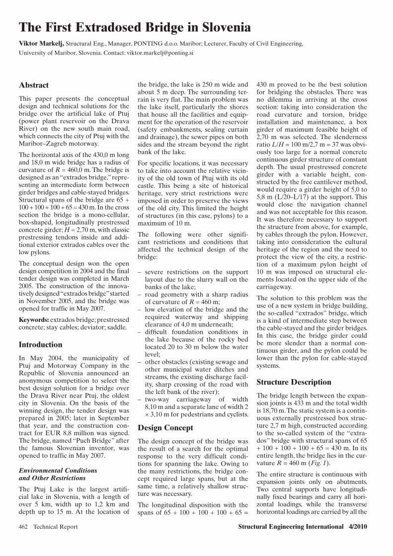
462 Technical Report Structural Engineering International 4/2010
The First Extradosed Bridge in SloveniaViktor Markelj, Structural Eng., Manager, PONTING d.o.o. Maribor; Lecturer, Faculty of Civil Engineering,
University of Maribor, Slovenia. Contact: [email protected]
the bridge, the lake is 250 m wide and about 5 m deep. The surrounding ter-rain is very flat. The main problem was the lake itself, particularly the shores that house all the facilities and equip-ment for the operation of the reservoir (safety embankments, sealing curtain and drainage), the sewer pipes on both sides and the stream beyond the right bank of the lake.
For specific locations, it was necessary to take into account the relative vicin-ity of the old town of Ptuj with its old castle. This being a site of historical heritage, very strict restrictions were imposed in order to preserve the views of the old city. This limited the height of structures (in this case, pylons) to a maximum of 10 m.
The following were other signifi-cant restrictions and conditions that affected the technical design of the bridge:
– severe restrictions on the support layout due to the slurry wall on the banks of the lake;
– road geometry with a sharp radius of curvature of R = 460 m;
– low elevation of the bridge and the required waterway and shipping clearance of 4,0 m underneath;
– diffi cult foundation conditions in the lake because of the rocky bed located 20 to 30 m below the water level;
– other obstacles (existing sewage and other municipal water ditches and streams, the existing discharge facil-ity, sharp crossing of the road with the left bank of the river);
– two-way carriageway of width 8,10 m and a separate lane of width 2 × 3,10 m for pedestrians and cyclists.
Design Concept
The design concept of the bridge was the result of a search for the optimal response to the very difficult condi-tions for spanning the lake. Owing to the many restrictions, the bridge con-cept required large spans, but at the same time, a relatively shallow struc-ture was necessary.
The longitudinal disposition with the spans of 65 + 100 + 100 + 100 + 65 =
430 m proved to be the best solution for bridging the obstacles. There was no dilemma in arriving at the cross section: taking into consideration the road curvature and torsion, bridge installation and maintenance, a box girder of maximum feasible height of 2,70 m was selected. The slenderness ratio L/H = 100 m/2,7 m = 37 was obvi-ously too large for a normal concrete continuous girder structure of constant depth. The usual prestressed concrete girder with a variable height, con-structed by the free cantilever method, would require a girder height of 5,0 to 5,8 m (L/20–L/17) at the support. This would close the navigation channel and was not acceptable for this reason. It was therefore necessary to support the structure from above, for example, by cables through the pylon. However, taking into consideration the cultural heritage of the region and the need to protect the view of the city, a restric-tion of a maximum pylon height of 10 m was imposed on structural ele-ments located on the upper side of the carriageway.
The solution to this problem was the use of a new system in bridge building, the so-called “extrados” bridge, which is a kind of intermediate step between the cable-stayed and the girder bridges. In this case, the bridge girder could be more slender than a normal con-tinuous girder, and the pylon could be lower than the pylon for cable-stayed systems.
Structure Description
The bridge length between the expan-sion joints is 433 m and the total width is 18,70 m. The static system is a contin-uous externally prestressed box struc-ture 2,7 m high, constructed according to the so-called system of the “extra-dos” bridge with structural spans of 65 + 100 + 100 + 100 + 65 = 430 m. In its entire length, the bridge lies in the cur-vature R = 460 m (Fig. 1).
The entire structure is continuous with expansion joints only on abutments. Two central supports have longitudi-nally fixed bearings and carry all hori-zontal loadings, while the transverse horizontal loadings are carried by all the
Abstract
This paper presents the conceptual design and technical solutions for the bridge over the artificial lake of Ptuj (power plant reservoir on the Drava River) on the new south main road, which connects the city of Ptuj with the Maribor–Zagreb motorway.
The horizontal axis of the 430,0 m long and 18,0 m wide bridge has a radius of curvature of R = 460,0 m. The bridge is designed as an “extrados bridge,” repre-senting an intermediate form between girder bridges and cable-stayed bridges. Structural spans of the bridge are 65 + 100 + 100 + 100 + 65 = 430 m. In the cross section the bridge is a mono-cellular, box-shaped, longitudinally prestressed concrete girder; H = 2,70 m, with classic prestressing tendons inside and addi-tional exterior extrados cables over the low pylons.
The conceptual design won the open design competition in 2004 and the final tender design was completed in March 2005. The construction of the innova-tively designed “extrados bridge” started in November 2005, and the bridge was opened for traffic in May 2007.
Keywords: extrados bridge; prestressed concrete; stay cables; deviator; saddle.
Introduction
In May 2004, the municipality of Ptuj and Motorway Company in the Republic of Slovenia announced an anonymous competition to select the best design solution for a bridge over the Drava River near Ptuj, the oldest city in Slovenia. On the basis of the winning design, the tender design was prepared in 2005; later in September that year, and the construction con-tract for EUR 8,8 million was signed. The bridge, named “Puch Bridge” after the famous Slovenian inventor, was opened to traffic in May 2007.
Environmental Conditions and Other Restrictions
The Ptuj Lake is the largest artifi-cial lake in Slovenia, with a length of over 5 km, width up to 1,2 km and depth up to 15 m. At the location of
x086.indd 462x086.indd 462 28/10/10 11:33 AM28/10/10 11:33 AM

Structural Engineering International 4/2010 Technical Report 463
supports. Three of the four intermediate supports are located in the reservoir.
The Substructure and Foundation
The substructure consists of two abut-ments and four intermediate piers, three of which are located in the res-ervoir and one on the shore. All the supports are on deep foundation with piles of diameter Φ 1,50 m. Owing to the low and relatively stiff supports, a rigid connection between the piers and the girder is not possible; however, all the supports have bearings at the top.
Supports 3 and 4 have fixed pot bear-ings at the top, while supports 1, 2 and 5, 6 have longitudinally movable and transversally fixed bearings.
The bearings summary is given in Table 1.
The intermediate piers are relatively low, 2,4 m thick and about 8 m wide, of a full cross section and are fixed into the pile head at the bottom (Fig. 2).
At the foundation in the lake, the soil mechanics data had to be taken into
account as well as the execution fea-sibility, structure maintenance and the hydraulic consequences. For piers, the foundation on eight piles of diameter Φ1,50 m with the oval-shaped “float-ing” pile head was foreseen in the design. As the superstructure lies on a curve, the piles are arranged asym-metrically so that they are uniformly loaded under the permanent load (the intermediate supports are more loaded on the inner side of the curvature—on the bearings, the ratio is 58–42%). At the pile head surface, it was simple to perform the temporary supporting during the cantilever construction.
Superstructure
The superstructure consists of three main elements:
– girder roadway structure;– low pylons;– inclined cables.
The roadway structure is a trapezoi-dal prestressed RC box of structural height 2,70 m (Fig. 3). The web thick-ness is 0,50 m, the upper slab is 18,16 m
Support in axis Bearing (kN)
Outside curve Inside curve
Abutment1 PNe 6100 PNe 5400
Pier 2 PNe 21 700 PNe 28 200
Pier 3 PN 23 000 PN 28 200
Pier 4 PN 23 000 PN 28 200
Pier 5 PNe 21 700 PNe 28 200
Abutment 6 PNe 6100 PNe 5400PNe—pot bearing movable in longitudinal direction. PN—pot bearing fixed.
Table 1: Bridge bearings
430
100100
2
65
Channel River Drava lake Stream
5
65
100100
100
65
2,9+36,80
3,0+01,80
3,1+01,80
3,2+01,80 3,3+01,80
3,3+66,80
430
6
3
2
1
4
1 3
100
4
65
5 6
Fig. 1: Spans 65 + 100 + 100 + 100 + 65 = 430 m in curvature R = 460 m
x086.indd 463x086.indd 463 28/10/10 11:33 AM28/10/10 11:33 AM
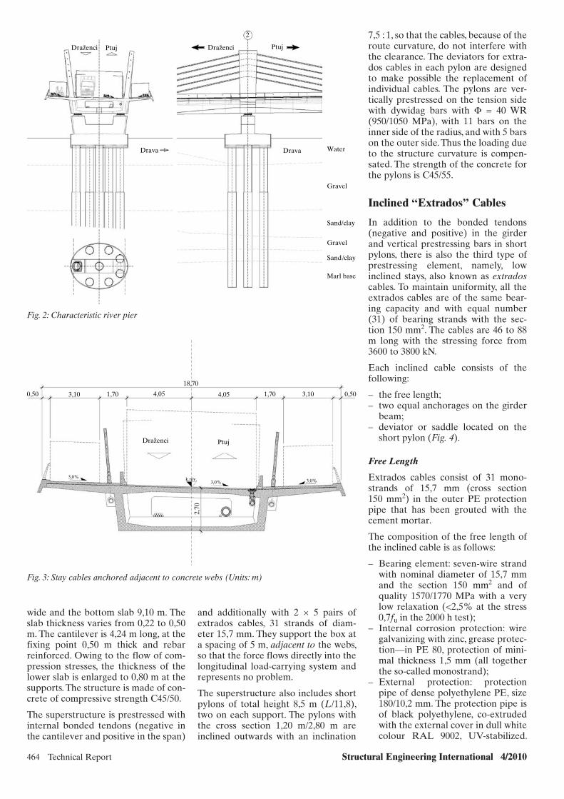
464 Technical Report Structural Engineering International 4/2010
wide and the bottom slab 9,10 m. The slab thickness varies from 0,22 to 0,50 m. The cantilever is 4,24 m long, at the fixing point 0,50 m thick and rebar reinforced. Owing to the flow of com-pression stresses, the thickness of the lower slab is enlarged to 0,80 m at the supports. The structure is made of con-crete of compressive strength C45/50.
The superstructure is prestressed with internal bonded tendons (negative in the cantilever and positive in the span)
and additionally with 2 × 5 pairs of extrados cables, 31 strands of diam-eter 15,7 mm. They support the box at a spacing of 5 m, adjacent to the webs, so that the force flows directly into the longitudinal load-carrying system and represents no problem.
The superstructure also includes short pylons of total height 8,5 m (L/11,8), two on each support. The pylons with the cross section 1,20 m/2,80 m are inclined outwards with an inclination
7,5 : 1, so that the cables, because of the route curvature, do not interfere with the clearance. The deviators for extra-dos cables in each pylon are designed to make possible the replacement of individual cables. The pylons are ver-tically prestressed on the tension side with dywidag bars with Φ = 40 WR (950/1050 MPa), with 11 bars on the inner side of the radius, and with 5 bars on the outer side. Thus the loading due to the structure curvature is compen-sated. The strength of the concrete for the pylons is C45/55.
Inclined “Extrados” Cables
In addition to the bonded tendons (negative and positive) in the girder and vertical prestressing bars in short pylons, there is also the third type of prestressing element, namely, low inclined stays, also known as extrados cables. To maintain uniformity, all the extrados cables are of the same bear-ing capacity and with equal number (31) of bearing strands with the sec-tion 150 mm2. The cables are 46 to 88 m long with the stressing force from 3600 to 3800 kN.
Each inclined cable consists of the following:
– the free length;– two equal anchorages on the girder
beam; – deviator or saddle located on the
short pylon (Fig. 4).
Free Length
Extrados cables consist of 31 mono-strands of 15,7 mm (cross section 150 mm2) in the outer PE protection pipe that has been grouted with the cement mortar.
The composition of the free length of the inclined cable is as follows:
– Bearing element: seven-wire strand with nominal diameter of 15,7 mm and the section 150 mm2 and of quality 1570/1770 MPa with a very low relaxation (<2,5% at the stress 0,7fu in the 2000 h test);
– Internal corrosion protection: wire galvanizing with zinc, grease protec-tion—in PE 80, protection of mini-mal thickness 1,5 mm (all together the so-called monostrand);
– External protection: protection pipe of dense polyethylene PE, size 180/10,2 mm. The protection pipe is of black polyethylene, co-extruded with the external cover in dull white colour RAL 9002, UV-stabilized.
Ptuj
2
Ptuj
3,0%3,0% 3,0%
Drava Drava Water
Gravel
Sand/clay
Gravel
Sand/clay
Marl base
DrazenciDrazenci
Fig. 2: Characteristic river pier
18,70
4,05
Drazenci Ptuj
3,0% 3,0%3,0% k.niv.
2,70
1,703,100,50 4,05 1,70 3,10 0,50
Fig. 3: Stay cables anchored adjacent to concrete webs (Units: m)
x086.indd 464x086.indd 464 28/10/10 11:33 AM28/10/10 11:33 AM
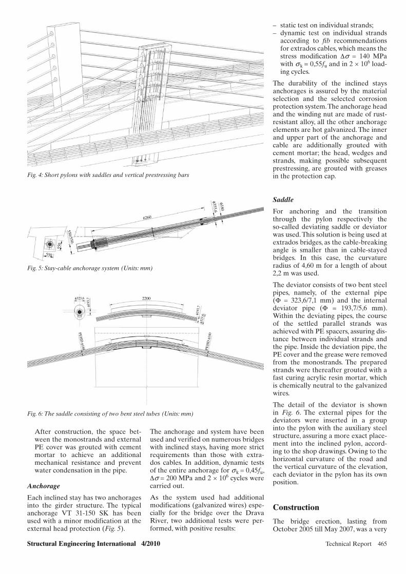
Structural Engineering International 4/2010 Technical Report 465
– static test on individual strands; – dynamic test on individual strands
according to fi b recommendations for extrados cables, which means the stress modifi cation Δs = 140 MPa with s k = 0,55fu and in 2 × 10⁶ load-ing cycles.
The durability of the inclined stays anchorages is assured by the material selection and the selected corrosion protection system. The anchorage head and the winding nut are made of rust-resistant alloy, all the other anchorage elements are hot galvanized. The inner and upper part of the anchorage and cable are additionally grouted with cement mortar; the head, wedges and strands, making possible subsequent prestressing, are grouted with greases in the protection cap.
Saddle
For anchoring and the transition through the pylon respectively the so-called deviating saddle or deviator was used. This solution is being used at extrados bridges, as the cable-breaking angle is smaller than in cable-stayed bridges. In this case, the curvature radius of 4,60 m for a length of about 2,2 m was used.
The deviator consists of two bent steel pipes, namely, of the external pipe (Φ = 323,6/7,1 mm) and the internal deviator pipe (Φ = 193,7/5,6 mm). Within the deviating pipes, the course of the settled parallel strands was achieved with PE spacers, assuring dis-tance between individual strands and the pipe. Inside the deviation pipe, the PE cover and the grease were removed from the monostrands. The prepared strands were thereafter grouted with a fast curing acrylic resin mortar, which is chemically neutral to the galvanized wires.
The detail of the deviator is shown in Fig. 6. The external pipes for the deviators were inserted in a group into the pylon with the auxiliary steel structure, assuring a more exact place-ment into the inclined pylon, accord-ing to the shop drawings. Owing to the horizontal curvature of the road and the vertical curvature of the elevation, each deviator in the pylon has its own position.
Construction
The bridge erection, lasting from October 2005 till May 2007, was a very
The anchorage and system have been used and verified on numerous bridges with inclined stays, having more strict requirements than those with extra-dos cables. In addition, dynamic tests of the entire anchorage for s k = 0,45fu, Δs = 200 MPa and 2 × 10⁶ cycles were carried out.
As the system used had additional modifications (galvanized wires) espe-cially for the bridge over the Drava River, two additional tests were per-formed, with positive results:
After construction, the space bet-ween the monostrands and external PE cover was grouted with cement mortar to achieve an additional mechanical resistance and prevent water condensation in the pipe.
Anchorage
Each inclined stay has two anchorages into the girder structure. The typical anchorage VT 31-150 SK has been used with a minor modification at the external head protection (Fig. 5).
Fig. 4: Short pylons with saddles and vertical prestressing barsφ180
φ355,6
6260
550/550
550
550
Fig. 5: Stay-cable anchorage system (Units: mm)
2200
φ193
,7φ193
,7
PE
HD
φ18
0PE
HD
φ180
φ323
,6
φ323,6
Fig. 6: The saddle consisting of two bent steel tubes (Units: mm)
x086.indd 465x086.indd 465 28/10/10 11:34 AM28/10/10 11:34 AM

466 Technical Report Structural Engineering International 4/2010
demanding task. The foundation in the lake was carried out with artificial islands that were built with the help of steel sheet piles. This was followed by deep foundation with piles of diame-ter Φ 1,50 m and of length 25 to 30 m, reaching the marl base. The transpor-tation of equipment and material on the lake was carried out through heavy barges.
The bridge deck was built by the bal-anced cantilever method with the help of inclined extrados cables. Movable scaffolding with segment length of 5 m was used for erection. Since the super-structure is of a constant height, the scaffold was not modified as for the usual variable height girders. The set-ting and prestressing of stay cables was performed. Doing this saved time, con-sequently reducing the duration of a single construction stage to one week, which is normal.
One of the particularities of the construction was the “extrados cables”, which were assembled near the bridge and then mounted as a whole through saddles in the pylon to anchorages (Fig. 7). Prestressing was performed with mono jacks from both sides, using the strand-by-strand method.
The stressing protocol ensured that each strand in the stay cable was ten-sioned with the same force at the end of the tensioning procedure. Cables have an ultimate load capacity of 8200 kN; in service stage being loaded with approximately 4000 kN.
Very complex was also the monitor-ing of deformations in construction stages, due to the flexible cantile-vered deck of the bridge (Figs. 8-11). The construction of such a bridge would not have been possible without the most modern software solutions in the field of cable-stayed bridges and the most accurate surveying equipment.
Conclusion
The solution employing the so called “extradosed bridge” system managed to ingeniously overcome numerous restrictions and difficul-ties imposed on the Drava River spanning. The sharp curvature, which confronted design and building with a very challenging task, was success-fully carried out by using some new design solutions and original struc-tural details.
Fig. 7: The balanced cantilever construction with the help of “extrados cables”
Fig. 8: Bridge construction
Fig. 9: Completed bridge
Fig. 10: Bridge over the Drava River at Ptuj, Slovenia
x086.indd 466x086.indd 466 28/10/10 11:34 AM28/10/10 11:34 AM
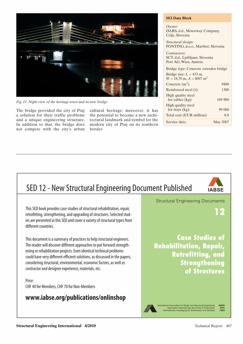
Structural Engineering International 4/2010 Technical Report 467
SEI Data BlockSEI Data Block
Owner:DARS, d.d., Motorway Company, Celje, Slovenia
Structural design:PONTING, d.o.o., Maribor, Slovenia
Contractors:SCT, d.d., Ljubljana, SloveniaPorr AG, Wien, Austria
Bridge type: Concrete extrados bridge
Bridge size: L = 433 m, W = 18,70 m, A = 8097 m2
Concrete (m3): 9488
Reinforced steel (t): 1300
High quality steel for cables (kg): 189 900
High quality steel for stays (kg): 99 060
Total cost (EUR million): 8,8
Service date: May 2007
The bridge provided the city of Ptuj a solution for their traffic problems and a unique engineering structure. In addition to that, the bridge does not compete with the city’s urban
Fig. 11: Night view of the heritage town and its new bridge
cultural heritage; moreover, it has the potential to become a new archi-tectural landmark and symbol for the modern city of Ptuj on its southern border.
Structural Engineering Documents
12
International Association for Bridge and Structural Engineering IABSE
Association Internationale des Ponts et Charpentes AIPC
Internationale Vereinigung für Brückenbau und Hochbau IVBH
Case Studies ofRehabilitation, Repair,
Retrofitting, andStrengthening
of Structures
www.iabse.org/publications/onlinshop
This SED book provides case studies of structural rehabilitation, repair,
retrofi tting, strengthening, and upgrading of structures. Selected stud-
ies are presented in this SED and cover a variety of structural types from
diff erent countries.
This document is a summary of practices to help structural engineers.
The reader will discover diff erent approaches to put forward strength-
ening or rehabilitation projects. Even identical technical problems
could have very diff erent effi cient solutions, as discussed in the papers,
considering structural, environmental, economic factors, as well as
contractor and designer experience, materials, etc.
SED 12 - New Structural Engineering Document Published
Price:
CHF 40 for Members, CHF 70 for Non-Members
IABSE
SED 12.indd 1 28/10/10 11:28 AM
x086.indd 467x086.indd 467 28/10/10 11:34 AM28/10/10 11:34 AM
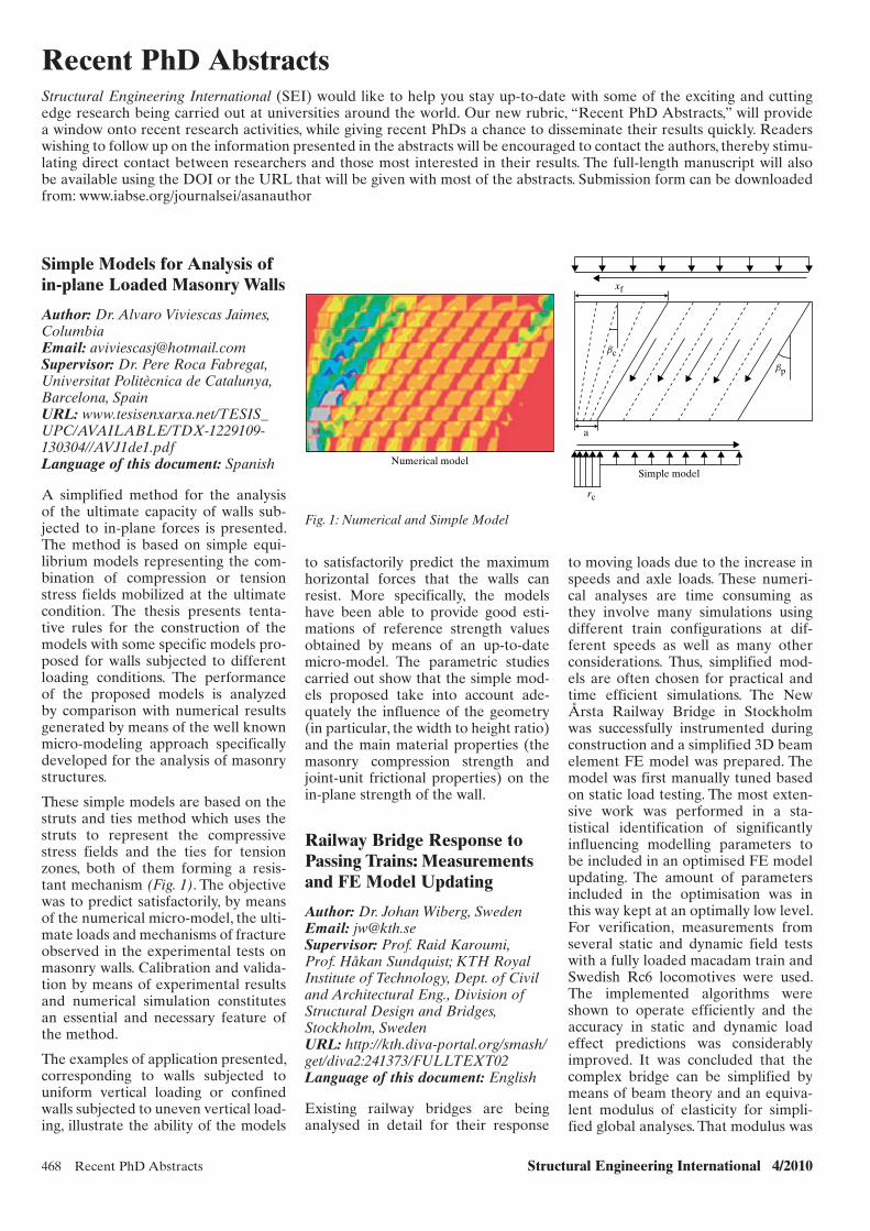
468 Recent PhD Abstracts Structural Engineering International 4/2010
to satisfactorily predict the maximum horizontal forces that the walls can resist. More specifically, the models have been able to provide good esti-mations of reference strength values obtained by means of an up-to-date micro- model. The parametric studies carried out show that the simple mod-els proposed take into account ade-quately the influence of the geometry (in particular, the width to height ratio) and the main material properties (the masonry compression strength and joint-unit frictional properties) on the in-plane strength of the wall.
Railway Bridge Response to Passing Trains: Measurements and FE Model Updating
Author: Dr. Johan Wiberg, SwedenEmail: [email protected]: Prof. Raid Karoumi, Prof. Håkan Sundquist; KTH Royal Institute of Technology, Dept. of Civil and Architectural Eng., Division of Structural Design and Bridges, Stockholm, SwedenURL: http://kth.diva-portal.org/smash/get/diva2:241373/FULLTEXT02Language of this document: English
Existing railway bridges are being analysed in detail for their response
to moving loads due to the increase in speeds and axle loads. These numeri-cal analyses are time consuming as they involve many simulations using different train configurations at dif-ferent speeds as well as many other considerations. Thus, simplified mod-els are often chosen for practical and time efficient simulations. The New Årsta Railway Bridge in Stockholm was successfully instrumented during construction and a simplified 3D beam element FE model was prepared. The model was first manually tuned based on static load testing. The most exten-sive work was performed in a sta-tistical identification of significantly influencing modelling parameters to be included in an optimised FE model updating. The amount of parameters included in the optimisation was in this way kept at an optimally low level. For verification, measurements from several static and dynamic field tests with a fully loaded macadam train and Swedish Rc6 locomotives were used. The implemented algorithms were shown to operate efficiently and the accuracy in static and dynamic load effect predictions was considerably improved. It was concluded that the complex bridge can be simplified by means of beam theory and an equiva-lent modulus of elasticity for simpli-fied global analyses. That modulus was
Recent PhD AbstractsStructural Engineering International (SEI) would like to help you stay up-to-date with some of the exciting and cutting edge research being carried out at universities around the world. Our new rubric, “Recent PhD Abstracts,” will provide a window onto recent research activities, while giving recent PhDs a chance to disseminate their results quickly. Readers wishing to follow up on the information presented in the abstracts will be encouraged to contact the authors, thereby stimu-lating direct contact between researchers and those most interested in their results. The full-length manuscript will also be available using the DOI or the URL that will be given with most of the abstracts. Submission form can be downloaded from: www.iabse.org/journalsei/asanauthor
Simple Models for Analysis of in-plane Loaded Masonry Walls
Author: Dr. Alvaro Viviescas Jaimes, ColumbiaEmail: [email protected]: Dr. Pere Roca Fabregat, Universitat Politècnica de Catalunya, Barcelona, SpainURL: www.tesisenxarxa.net/TESIS_UPC/AVAILABLE/TDX-1229109-130304//AVJ1de1.pdfLanguage of this document: Spanish
A simplified method for the analysis of the ultimate capacity of walls sub-jected to in-plane forces is presented. The method is based on simple equi-librium models representing the com-bination of compression or tension stress fields mobilized at the ultimate condition. The thesis presents tenta-tive rules for the construction of the models with some specific models pro-posed for walls subjected to different loading conditions. The performance of the proposed models is analyzed by comparison with numerical results generated by means of the well known micro-modeling approach specifically developed for the analysis of masonry structures.
These simple models are based on the struts and ties method which uses the struts to represent the compressive stress fields and the ties for tension zones, both of them forming a resis-tant mechanism (Fig. 1). The objective was to predict satisfactorily, by means of the numerical micro-model, the ulti-mate loads and mechanisms of fracture observed in the experimental tests on masonry walls. Calibration and valida-tion by means of experimental results and numerical simulation constitutes an essential and necessary feature of the method.
The examples of application presented, corresponding to walls subjected to uniform vertical loading or confined walls subjected to uneven vertical load-ing, illustrate the ability of the models
Simple modelNumerical model
a
rc
xf
bc
bp
Fig. 1: Numerical and Simple Model
sei_PhD Abstracts.indd 468sei_PhD Abstracts.indd 468 10/28/10 10:17 AM10/28/10 10:17 AM
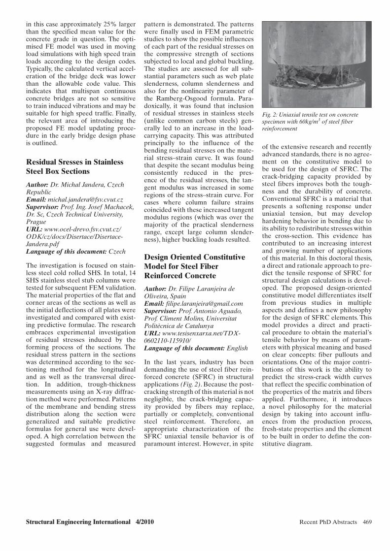
Structural Engineering International 4/2010 Recent PhD Abstracts 469
of the extensive research and recently advanced standards, there is no agree-ment on the constitutive model to be used for the design of SFRC. The crack-bridging capacity provided by steel fibers improves both the tough-ness and the durability of concrete. Conventional SFRC is a material that presents a softening response under uniaxial tension, but may develop hardening behavior in bending due to its ability to redistribute stresses within the cross-section. This evidence has contributed to an increasing interest and growing number of applications of this material. In this doctoral thesis, a direct and rationale approach to pre-dict the tensile response of SFRC for structural design calculations is devel-oped. The proposed design-oriented constitutive model differentiates itself from previous studies in multiple aspects and defines a new philosophy for the design of SFRC elements. This model provides a direct and practi-cal procedure to obtain the material’s tensile behavior by means of param-eters with physical meaning and based on clear concepts: fiber pullouts and orientations. One of the major contri-butions of this work is the ability to predict the stress-crack width curves that reflect the specific combination of the properties of the matrix and fibers applied. Furthermore, it introduces a novel philosophy for the material design by taking into account influ-ences from the production process, fresh-state properties and the element to be built in order to define the con-stitutive diagram.
pattern is demonstrated. The patterns were finally used in FEM parametric studies to show the possible influences of each part of the residual stresses on the compressive strength of sections subjected to local and global buckling. The studies are assessed for all sub-stantial parameters such as web plate slenderness, column slenderness and also for the nonlinearity parameter of the Ramberg-Osgood formula. Para-doxically, it was found that inclusion of residual stresses in stainless steels (unlike common carbon steels) gen-erally led to an increase in the load-carrying capacity. This was attributed principally to the influence of the bending residual stresses on the mate-rial stress–strain curve. It was found that despite the secant modulus being consistently reduced in the pres-ence of the residual stresses, the tan-gent modulus was increased in some regions of the stress–strain curve. For cases where column failure strains coincided with these increased tangent modulus regions (which was over the majority of the practical slenderness range, except large column slender-ness), higher buckling loads resulted.
Design Oriented Constitutive Model for Steel Fiber Reinforced Concrete
Author: Dr. Filipe Laranjeira de Oliveira, SpainEmail: [email protected]: Prof. Antonio Aguado, Prof. Climent Molins, Universitat Politècnica de CatalunyaURL: www.tesisenxarxa.net/TDX-0602110-115910/Language of this document: English
In the last years, industry has been demanding the use of steel fiber rein-forced concrete (SFRC) in structural applications (Fig. 2). Because the post-cracking strength of this material is not negligible, the crack-bridging capac-ity provided by fibers may replace, partially or completely, conventional steel reinforcement. Therefore, an appropriate characterization of the SFRC uniaxial tensile behavior is of paramount interest. However, in spite
in this case approximately 25% larger than the specified mean value for the concrete grade in question. The opti-mised FE model was used in moving load simulations with high speed train loads according to the design codes. Typically, the calculated vertical accel-eration of the bridge deck was lower than the allowable code value. This indicates that multispan continuous concrete bridges are not so sensitive to train induced vibrations and may be suitable for high speed traffic. Finally, the relevant area of introducing the proposed FE model updating proce-dure in the early bridge design phase is outlined.
Residual Sresses in Stainless Steel Box Sections
Author: Dr. Michal Jandera, Czech RepublicEmail: [email protected]: Prof. Ing. Josef Machacek, Dr. Sc, Czech Technical University, PragueURL: www.ocel-drevo.fsv.cvut.cz/ODK/cz/docs/Disertace/Disertace-Jandera.pdfLanguage of this document: Czech
The investigation is focused on stain-less steel cold rolled SHS. In total, 14 SHS stainless steel stub columns were tested for subsequent FEM validation. The material properties of the flat and corner areas of the sections as well as the initial deflections of all plates were investigated and compared with exist-ing predictive formulae. The research embraces experimental investigation of residual stresses induced by the forming process of the sections. The residual stress pattern in the sections was determined according to the sec-tioning method for the longitudinal and as well as the transversal direc-tion. In addition, trough-thickness measurements using an X-ray diffrac-tion method were performed. Patterns of the membrane and bending stress distribution along the section were generalized and suitable predictive formulas for general use were devel-oped. A high correlation between the suggested formulas and measured
Fig. 2: Uniaxial tensile test on concrete specimen with 60kg/m3 of steel fiber reinforcement
sei_PhD Abstracts.indd 469sei_PhD Abstracts.indd 469 10/28/10 10:17 AM10/28/10 10:17 AM

470 Eminent Structural Engineer Structural Engineering International 4/2010
Eminent Structural Engineer: Christian Menn—Bridge Designer and Builder Eugen Brühwiler, Prof., Dr. Civil Eng., ETH, Ecole Polytechnique Fédérale de Lausanne (EPFL), Lausanne, Switzerland.
Contact: [email protected]
Introduction
Christian Menn (Fig. 1) ranks among the most important and creative bridge design engineers of the recent decades. His bridges are witnesses of his exclu-sive engagement in bridge engineering and more than 50 years of continu-ous experimentation in conceptual, structural and aesthetic design. They teach us that the true art of struc-tural engineering is characterized by innovation and imagination with the objective to improve the environment through structural art. His work has been exhibited at various universi-ties in Europe and at art museums across the United States, and attests to his extraordinary creativity and abso-lute mastery of bridge engineering.
Bridges in Switzerland
The first bridges designed by him (Fig. 2) were inspired by the innovative bridge forms—the three-hinged hol-low box girder and the deck-stiffened arch—of his Swiss predecessor Robert Maillart. After 1960, Menn developed his own style of the arch bridge. This consists of a monolithic frame sys-tem composed of a thin polygonal arch supporting slender cross walls at a wide spacing, and a stiff partially prestressed box girder deck with a wide cantilevered roadway. The most prominent example is the 100 m span Reichenau Bridge (Fig. 3) over the Rhine River, which represents a new form for deck-stiffened arch bridges with long spans. Menn has used this
Brief CV
1927 Born on 3 March in Meiringen, Switzerland.
1950 Graduated from the Swiss Federal Institute of Technology (ETH) Zurich with a degree in Civil Engineering.
1953 Accepted a position as assistant to Professor Pierre Lardy at ETH Zurich, where he completed his doctoral degree in Civil Engineering in 1956.
1956 Worked as an engineer with the French construction contrac-tor Dumez, on the construction of the UNESCO building in Paris.
1957 Established his own engineering design office, specializing in reinforced concrete construction, in Chur, Switzerland.
1959 Built his first bridges at Letziwald and Cröt in Switzerland.
1971–1992 Was Professor of Structural Engineering at the Swiss Federal Institute of Technology (ETH) Zurich.
Since 1992 Commenced private practice as a consulting engineer.
1996 Received honorary doctorate from the University of Stuttgart.
2008 Received honorary doctorate from the Ecole Polytechnique Fédérale de Lausanne (EPFL).
2009 Received the International Award of Merit in Structural Engineering from IABSE.
Fig. 1: Christian Menn
Fig. 2: Letziwald bridge at Avers, Switzerland, 1959
Fig. 3: Reichenau bridge at Tamins, Switzerland, 1963
x107.indd 470x107.indd 470 10/26/10 12:32 AM10/26/10 12:32 AM
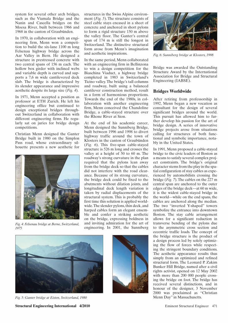
Structural Engineering International 4/2010 Eminent Structural Engineer 471
Bridge was awarded the Outstanding Structure Award by the International Association for Bridge and Structural Engineering (IABSE).
Bridges Worldwide
After retiring from professorship in 1992, Menn began a new vocation as consultant for the design of several significant bridges around the world. This pursuit has allowed him to fur-ther develop his passion for the art of bridge design. A series of innovative bridge projects arose from situations calling for structures of both func-tional and symbolic importance, nota-bly in the United States.
In 1991, Menn proposed a cable-stayed bridge to the civic leaders of Boston as a means to satisfy several complex proj-ect constraints. The bridge’s original character stems from the play in the spa-tial configuration of stay cables as expe-rienced by automobilists crossing the bridge (Fig. 7). The cables on the 227 m central span are anchored to the outer edges of the bridge deck—at 60 m wide, it is the widest cable-stayed bridge in the world—while on the end spans, the cables are anchored along the median. The two “inverted Y-shaped” towers symbolize the entrance into downtown Boston. The stay cable arrangement allows for a significant reduction in transverse bending of the pylons due to the asymmetric cross section and eccentric traffic loads. The concept of the bridge structure is the product of a design process led by solely optimiz-ing the flow of forces while respect-ing the stringent boundary conditions. The aesthetic appearance results thus simply from an optimized and refined structural form. The Leonard P. Zakim Bunker Hill Bridge, named after a civil rights activist, opened on 12 May 2002 with more than 200 000 people cross-ing the bridge on foot. The bridge has received several distinctions, and in honour of the designer, 3 November 2000 was proclaimed as “Christian Menn Day” in Massachusetts.
structures in the Swiss Alpine environ-ment (Fig. 5). The structure consists of steel cable stays encased in a sheet of concrete and anchored in short pylons to form a rigid structure 150 m above the valley floor. The Ganter’s central span of 174 m is still the longest in Switzerland. The distinctive structural form arose from Menn’s imagination and aesthetic inspirations.
In the same period, Menn collaborated with an engineering firm in Bellinzona to win a design competition for the Biaschina Viaduct, a highway bridge completed in 1983 in Switzerland’s Ticino valley. The bridge’s tall columns and roadway, built using a balanced cantilever construction method, result in a form of harmonious proportions. Towards the end of the 1980s, in col-laboration with another engineering firm, Menn conceived the Chandoline Bridge, a cable-stayed structure over the Rhone River at Sion.
At the end of his academic career, Menn designed the Sunniberg Bridge, built between 1996 and 1998 to divert highway traffic around the town of Klosters in the canton of Graubünden (Fig. 6). This five-span cable-stayed structure is 526 m long and crosses the valley at a height of 50 to 60 m. The roadway’s strong curvature in the plan required that the pylons lean away from the bridge deck so that the cables did not interfere with the road clear-ance. Because of its strong curvature, the bridge deck could be fixed to the abutments without dilation joints, and longitudinal deck length variation is taken by radial displacements of the structural system. This is probably the first time this solution is applied world-wide. The slender pylons, thin deck, and harped cables form an elegant ensem-ble and confer a striking aesthetic on the bridge, expressing boldness in and inviting admiration for the art of engineering. In 2001, the Sunniberg
system for several other arch bridges, such as the Viamala Bridge and the Nanin and Cascella bridges on the Moesa River, built between 1966 and 1968 in the canton of Graubünden.
In 1970, in collaboration with an engi-neering firm, Menn won a competi-tion to build the six-lane 1100 m long Felsenau highway bridge across the Aar Valley in Bern. He designed a structure in prestressed concrete with two central spans of 156 m each. The hollow box girder with inclined webs and variable depth is curved and sup-ports a 7,6 m wide cantilevered deck slab. The bridge is characterized by its slender appearance and impressive aesthetic despite its large size (Fig. 4).
In 1971, Menn accepted a position as professor at ETH Zurich. He left his engineering office but continued to design exceptional bridges through-out Switzerland in collaboration with different engineering firms. He regu-larly sat on juries for bridge design competitions.
Christian Menn designed the Ganter Bridge built in 1980 on the Simplon Pass road, whose extraordinary sil-houette presents a new aesthetic for
Fig. 4: Felsenau bridge at Berne, Switzerland, 1975
Fig. 5: Ganter bridge at Eisten, Switzerland, 1980
Fig. 6: Sunniberg bridge at Klosters, 1998
x107.indd 471x107.indd 471 10/26/10 12:32 AM10/26/10 12:32 AM

472 Eminent Structural Engineer Structural Engineering International 4/2010
Future Bridge Project
In Switzerland, near the birthplace of Menn, plans to raise the Grimsel dam and lake require redrawing of the road over the Grimsel Pass which has to cross more than 300 m across the artificial lake. In 2005, Christian Menn designed a cable-stayed bridge crossing the lake with a single span of 352 m. This will be the longest in Switzerland, supported by two vertical 75-m high inversed Y-shaped pylons. The aesthetic expression is character-ized by the slender deck and purely shaped pylons, as well as the semi-fan arrangement of the stay cables and their concrete anchorage blocks shaped like mountain crystals (Fig. 9).
Lessons in Bridge Design
Christian Menn has designed arch, box girder and cable-stayed bridge struc-tures. He has developed new ideas for each of these types of structural sys-tems in order to create unique forms and an original aesthetic. His bridges are the result of a design process reduc-ing structural elements to meet the given functional and environmental requirements. They are characterized by harmonious proportioning of struc-tural elements, a slender appearance and coherent integration of shapes, which continually led to new creations and expressions. Menn’s works are among the most beautiful bridges built in the last 50 years; they are symbols of modern technology, and they establish a technical aesthetic.
Menn’s bridges express technical effi-ciency with an accent on slenderness and transparency. They emphasize to us the importance of understanding how structural systems function. A sound engineering concept is the solid basis for a far-reaching aesthetic quality and for finding simple yet elegant struc-tures. Guided by the basics of structural mechanics and natural sciences, this approach continues to be very efficient and valuable, in particular nowadays, when (architect-led) bridge designs, often based on a spectacular metaphoric idea rather than on an efficient struc-tural concept, have produced structures that are excessively expensive to build and maintain and thus are controversial.
In his numerous lectures on bridge design, Christian Menn has always insisted that the art of structural engi-neering should be appreciated and be given much more importance, in particu-lar, in bridge design competitions and in the education of structural engineers.
Menn’s conceptual designs for a bridge crossing the valley in front of Hoover Dam near Las Vegas, the east span of the San Francisco Oakland Bay Bridge, a double self-anchored suspension bridge for crossing the Ohio River at Louisville and a new Inner Belt Bridge in Cleveland were unfortunately all not considered, sometimes because of their seemingly too innovative nature, and more conservative approaches were preferred instead.
On the Princeton University campus, Menn’s design of the slender pedes-trian bridge passing over Washington Road took the form of a bold arch. The Streicker Bridge, completed in 2010 and named after its principal benefactor, links four buildings designed by inter-nationally acclaimed architects (Fig. 8).
In 2007, Christian Menn was asked to propose bridge designs to provide access to a large island to be devel-oped in Abu Dhabi in the United Arab Emirates. For the two largest most em blematic bridges, he proposed an arch rising above the roadway surface from which the bridge deck is suspended, and a cable-stayed bridge with a single “spindle-shaped” pylon supporting a wide, softly curving roadway just a few meters above the water surface. These projects are currently in the design development phase, and construction is expected to begin in the near future.
Menn developed the designs of sev-eral other major bridges in the United States. He designed the winning pro-posal for a bridge competition held in 1998 for the 2 km long Woodrow Wilson Bridge crossing the Potomac River, south of Washington, DC, but only the basic structural system remained from Menn’s original design. The originally slender, elegant V-shaped piers were abandoned in favor of unmotivated curved massive elements.
Since 2001, Menn has developed sev-eral designs for a new bridge crossing the Niagara River near its famous falls. These designs for the “Peace Bridge” between Buffalo and Fort Erie have won the support largely of the public and local leaders, but the official pro-cess of approvals is still ongoing.
Fig. 7: Leonard P. Zakim Bunker Hill Bridge in Boston, USA, 2002
Fig. 8: Streicker Pedestrian Bridge over Washington Road on the Princeton University Campus, Princeton, USA, 2009
Fig. 9: Grimsel lake bridge at Guttannen, Switzerland (Project)
x107.indd 472x107.indd 472 10/26/10 12:33 AM10/26/10 12:33 AM

Structural Engineering International 4/2010 Panorama 473
IABSE Annual MeetingsVenice, Italy, September 19–21, 2010
and enjoyed the social events together with committee members: on Sunday Ms Evelyne Stampfli, Deputy Consul General of Switzerland, gave a recep-tion at the Excelsior Hotel. On Monday evening, Jacques Combault, President of IABSE welcomed all delegates, and
The 2010 Annual Meetings were held at the Palazzo del Casino, at the Lido in Venice, prior to the 34th IABSE Symposium. There was a good atten-dance with 140 participants and 55 accompanying persons. Accompanying persons discovered Venice and islands
Predrag (Pete) Popovic, USA, New President of IABSE
SEI Editorial Board and Nominees
Carlo Urbano, Chair of the Italian Group, in his turn welcomed all to Venice with drinks and delicious food on Tuesday evening.
The Annual Meetings included the Administrative, Executive, Permanent Committee and Chair National Groups, Technical Committee, Editorial, Cor-respondents and E-Learning Boards, Working Commissions, Work ing Groups, Scientific Committees, Young Engineers Board, the Advisory Group to the Executive Committee and the IABSE Foundation Council.
The Permanent Committee approved the annual statement of accounts 2009 and the budget 2011. The annual accounts 2009 closed with total net revenues of CHF 989'066 and an excess of revenues of CHF 17'505. The Association funds amount to CHF 467'658 as on December 31, 2009. For the year 2011 a budget with total net revenues of CHF 1'087'700 was approved.
The Permanent Committee changed the article 14 of the By-Laws and made English the sole official language of IABSE as from January 1, 2011.
Jacques Combault ended his term as President on October 31, 2010. At the Closing Ceremony of the 34th IABSE Symposium he thanked his colleagues on the Administrative and Executive Committees, and all those who have made the Technical Committee more dynamic and efficient by encouraging the creation of new Working Groups and making IABSE E-Learning become a reality. During the three years of his presidency several suc-cessful international events were held: the Congress in Chicago, Symposia in Bangkok and Conferences in Helsinki and Dubrovnik, a Bridge Workshop and spectacular tour in China. Jacques Combault attended four Outstanding Structure Award plaque presenta-tions and welcomed one new National Group to the Association. The 80 years of IABSE were celebrated by making all IABSE publications from
1929–1999 available for free online to the general public. A new more dynamic website is on its way to serve the Association for an even better exchange of structural engineering knowledge.
Pete Popovic took the opportunity during the Closing Ceremony to thank Jacques Combault and his wife Danièle, who has assisted and supported her husband during his presidency.
Pete Popovic from Wiss, Janney, Elstener Associates, Inc., USA, has taken office as President of IABSE on November 1, 2010, for a period of three years. He is the second IABSE President from USA. Pete Popovic is Member of IABSE since 1985 and knows the Association well. He has been Chair of Working Commission 8, Member of the Technical Committee, Member of the Outstanding Structure
Award Committee and Vice-President of IABSE. His contributions to IABSE
Pete Popovic, USA, President of IABSE
Panorama.indd 473Panorama.indd 473 10/28/10 2:05 PM10/28/10 2:05 PM

474 Panorama Structural Engineering International 4/2010
conferences are numerous and he was the Chair of the Organising Committee for the Chicago Congress in 2008.
Pete Popovic’s fields of expertise are the design, assessment and repairs of bridges and buildings. He has in partic-ular expertise in assessment and repair of concrete structures and of fatigue damage in steel bridges, and exterior facades of high-rise buildings.
During the first ten years of practice, he participated in structural design of major steel bridges and rapid tran-sit systems in Chicago, New York and Atlanta, USA. He was engaged in the design of post-tensioned box girder bridges in Kuwait. Over the last 30 years, he has evaluated and designed repairs for over 1500 structures. Major projects included assessment of steel bridges for fatigue damage, investiga-tion of collapses of bridges and build-ings, assessment and design of repairs for exterior facades of high-rise build-ings up to 60-stories tall, and assess-ment and repair of over 100 parking structures.
Pete Popovic has published over 40 technical papers on assessment, load testing, strengthening and repair of bridges, buildings and parking struc-tures and is a contributing author to
several books. He has received awards from the International Concrete Repair Institute for innovative repair projects and is an invited lecturer at the University of Wisconsin, USA and World of Concrete (USA and Mexico) on topics of concrete repairs, rehabili-tation of parking structures, and pre-vention of structural failures.
As President of IABSE Pete Popovic intends, to work in making IABSE more visible and increasing IABSE membership. His goal is to have National Groups play an increasing role in recruiting new members and retaining existing members. The goal is to increase IABSE membership by 500 over the next three years.
IABSE Awards 2010
Jacques Combault, President of IABSE, presented the IABSE Awards at the Permanent Committee (Honorary Memberships) and at the Opening Ceremony of the 34th IABSE Symposium in Venice on the 21st and 22nd of September.
Honorary Membership
Honorary Membership is presented to an Individual Member of IABSE, for exceptionally great services rendered to the Association.
The Executive Committee of IABSE has awarded Honorary Membership to Prof. Aarne Jutila, Finland. The President of IABSE presented the Award at the Permanent Committee meeting on September 21, 2010, ‘in recognition to his outstand-ing and dedicated services to the Association’.
Born 1940 in Helsinki, Aarne Jutila received his Civil Engineering degree at Helsinki University of Technology (TKK) in 1966, with major sub-ject “Bridge Engineering”. After graduation he studied a year at ETH, Zurich, as “Bundesstipendiat” under the guidance of Bruno Thürlimann. Later he worked as bridge designer
at Kjessler and Mannerstråle AB in Stockholm and Tapiola, Finland, as Assistant Lecturer at Queen’s University of Belfast, Northern Ireland, and as section chief at the Finnish Road Administration’s bridge design office (TVH) in Helsinki before found-ing of and working for three consulting engineering companies. Besides that he also worked as assistant, laboratory engineer and, since 1984, as Professor of Bridge Engineering at TKK. He retired in August 2008 and contin-ues his bridge engineering activity as Managing Director of Extraplan Oy, consulting engineers, that he founded in 1977.
Aarne Jutila joined IABSE in 1967, and has since then held numerous functions within the Association: Secretary of the Finnish Group 1972–88 and Chair since that, Vice-Chair of the Organising Committee of the 1988 Helsinki Congress, SEI
Aarne Jutila, Finland
Jacques and Danièle Combault and Pete Popovic
Panorama.indd 474Panorama.indd 474 10/28/10 2:05 PM10/28/10 2:05 PM
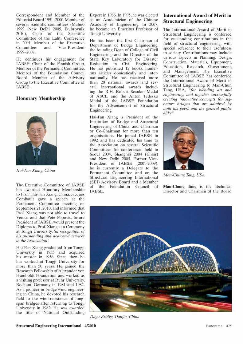
Structural Engineering International 4/2010 Panorama 475
International Award of Merit in Structural Engineering
The International Award of Merit in Structural Engineering is conferred for outstanding contributions in the field of structural engineering, with special reference to their usefulness to society. Contributions may include various aspects in Planning, Design, Construction, Materials, Equipment, Education, Research, Government, and Management. The Executive Committee of IABSE has conferred the International Award of Merit in Structural Engineering to Man-Chun Tang, USA, “for blending art and engineering, and together successfully creating innovative concepts for sig-nature bridges that are admired by both his peers and the general public alike”.
Expert in 1986. In 1995, he was elected as an Academician of the Chinese Academy of Engineering. In 2007, he became an Emeritus Professor of Tongji University.
He has been the first Chairman of Department of Bridge Engineering, the founding Dean of College of Civil Engineering, and the Director of the State Key Laboratory for Disaster Reduction in Civil Engineering. He has published 12 books, numer-ous articles domestically and inter-nationally. He has received more than 20 national awards and sev-eral international awards includ-ing the R.H. Robert Scanlan Medal of ASCE and the Anton Tedesko Medal of the IABSE Foundation for the Advancement of Structural Engineering.
Hai-Fan Xiang is President of the Insti tution of Bridge and Structural Engineering of China, and Chairman or Co-Chairman for more than ten organisations. He joined IABSE in 1992 and has dedicated his time to the Association on several Scientific Committees for conferences held in Seoul 2004, Shanghai 2004 (Chair) and New Delhi 2005. Former Vice-President of IABSE (2001-2009), he is currently a Delegate to the Permanent Committee and on the Structural Engineering International (SEI) Advisory Board and a Member of the Foundation Council of IABSE.
Correspondent and Member of the Editorial Board 1991–2000, Member of several scientific committees (Malmö 1999, New Delhi 2005, Dubrovnik 2010), Chair of the Scientific Committee of the Lahti Conference in 2001, Member of the Executive Committee and Vice-President 1999–2007.
He continues his engagement for IABSE: Chair of the Finnish Group, Member of the Permanent Committee, Member of the Foundation Council Board, Member of the Advisory Group to the Executive Committee of IABSE.
Honorary Membership
Hai-Fan Xiang, ChinaMan-Chung Tang, USA
Dagu Bridge, Tianjin, China
The Executive Committee of IABSE has awarded Honorary Membership to Prof. Hai-Fan Xiang, China. Jacques Combault gave a speech at the Permanent Committee meeting on September 21, 2010, and informed that Prof. Xiang, was not able to travel to Venice and that Pete Popovic, future President of IABSE, would present the Diploma to Prof. Xiang at a Ceremony at Tongji University, ‘in recognition of his outstanding and dedicated services to the Association’.
Hai-Fan Xiang graduated from Tongji University in 1955 and acquired his master in 1958. Since then he has worked at Tongji University for more than 50 years. He gained the Research Fellowship of Alexander von Humboldt Foundation and worked as a visiting professor at Ruhr University, Bochum, Germany in 1981 and 1982. As a pioneer in bridge wind engineer-ing in China, he devoted his research field to the wind-resistance of long-span bridges after returning to Tongji University in 1982. He was awarded the title of National Outstanding
Man-Chung Tang is the Technical Director and Chairman of the Board
Panorama.indd 475Panorama.indd 475 10/28/10 2:05 PM10/28/10 2:05 PM

476 Panorama Structural Engineering International 4/2010
Structural Engineering International (SEI), encouraging and rewarding con-tributions of the highest quality. It was first launched in 1991.
The Outstanding Paper Award Com-mittee, chaired by Professor Akira Wada, Japan, has conferred the Outstanding Paper Award to Andreas Breum Ølgaard, Jens Henrik Nielsen, and John Forbes Olesen, Denmark, for their paper:
“Design of Mechanically Reinforced Glass Beams: Modelling and Experiments” Published in Structural Engineering International (SEI) May 2009.
The paper is a study on how to obtain a ductile behaviour of a composite transparent structural element. The structural element is constructed by gluing a steel strip to the bot-tom face of a float glass beam using an epoxy adhesive. The compos-ite beam is examined by four point bending tests, and the mechanisms of the beam are discussed. Analogies to reinforced concrete beam theory are made; thus, four different design criteria, depending on the reinforce-ment ratio, are investigated. Analytical expressions are derived that are capa-ble of describing the behaviour in an uncracked stage, a linear cracked stage and a yield stage. A finite element model, capable of handling the crack-ing of the glass by killing elements, is presented.
Both analytical and numerical simu-lations are in fairly good agreement with the experimental observations. It appears that the reinforcement ratio is limited by the risk of anchorage failure and must be adjusted accord-ingly to obtain safe failure behaviour in a normal reinforced mode. Analysis of anchorage failure is made through a modified Volkersen stress analysis. Furthermore, different aspects of the design philosophy of reinforced glass beams are presented.
Outstanding Structure Award
The Outstanding Structure Award (OStrA) was established in 1998. It is one of the highest distinctions awarded by IABSE and recognises, in differ-ent regions of the world, some of the most remarkable, innovative, creative or otherwise stimulating structures completed within the last few years. The Outstanding Structure Award
recognition of his significant involve-ment in many major bridge projects, specially for his contribution in the design, project of Montabliz Viaduct’.
Roberto Revilla Angulo, was born in Bilbao (Spain) in 1970. He studied at the Technical Civil Engineers University College of Santander, and graduated in 1995. He has since then worked with Apia XXI, where he has been the Head of the Structures Department since 2000. At the time he is finish-ing his Doctoral Thesis “Stability of great high piers of bridges built by cantilever method”, at the Structural and Mechanical Department at the University of Cantabria. Montabliz Viaduct has allowed him to participate in some research works such as special studies of earthquake, wind and fire; wind tunnel tests; terrain-structure interaction studies of the foundation of piers and monitoring both static and dynamic structural behaviour during its construction.
Important projects he has developed include: Navas Viaduct, Caviedes Viaduct, Viaduct over Voltoya River, New Bridge over Ebro Reservoir, Santander’s Bay Ring Footbridge, Montabliz Viaduct and New Bridge over Llobregat River. He has won the Idea Tenders of the New Bridge over Guadaira River (Sevilla) and the New Bridge over Llobregat River (Barcelona). Roberto Revilla’s pro-fessional passion has always been to design bridges taking care of aesthet-ics and in full harmony with the sur-rounding, breaking civil engineering architecture barrier.
Outstanding Paper Award
The Outstanding Paper Award is remitted each year to the author(s) of a paper published in the preced-ing year’s issues of the IABSE Journal
of T.Y. Lin International, a globally recognised consulting firm with head-quarters in San Francisco, USA.
Man-Chung Tang received his Doctor of Civil Engineering in 1965 from the Technical University Darmstadt, Germany. His career spans more than 44 years, and encompasses design-ing and constructing over 100 bridges worldwide, including 32 cable-stayed bridges, four major suspension bridges, and numerous segmental bridges. A true leader and icon, Dr. Tang’s con-tributions to innovations in bridge design are demonstrated through teaching, writing over 100 technical papers, and offering numerous presen-tations. He is an honorary professor at ten universities, a member of the U.S. National Academy of Engineering, a foreign member of Chinese Academy of Engineering, and an honorary mem-ber of the American Society of Civil Engineers (ASCE).
A world authority on cable-stayed bridges, Man-Chung Tang served as Chairman of the American Society of Civil Engineers (ASCE) committee on cable-suspended bridges and published the definitive guideline for the design of cable-stayed bridges, used today by engineers all over the world. Dr. Tang is also a founding member of the Post-Tensioning Institute (PTI) committee that published “Recommendations for the Design and Testing of Stay Cables,” also used worldwide.
Man-Chung Tang’s bridges, besides being safe, functional and economical, are considered works of art–beautiful structures that blend seamlessly with their surroundings. It is often quoted that “the sun never sets on a Dr. Tang bridge,” as his designs can be found all around the globe. Man-Chung Tang continues to advance the field of bridge engineering as an innovator and an educator and he has been con-tinually recognised by his peers for his dedication to the field.
IABSE Prize
The IABSE Prize was established in 1982 to honour a Member early in his, or her career for an outstanding achievement in the field of structural engineering, in Research, Design or Construction. The Prize is presented to Individual Members of IABSE, forty years of age or younger.
The Executive Committee of IABSE has presented the IABSE Award 2010 to Roberto Revilla Angulo, Spain, ‘in
Roberto Revilla Angulo, Spain
Panorama.indd 476Panorama.indd 476 10/28/10 2:05 PM10/28/10 2:05 PM

Structural Engineering International 4/2010 Panorama 477
box carved from a theoretically per-fect and repetitious array of bubbles. The final building is satisfying on many levels: as a beautiful object; a poetic expression of bubbles and water; the physical manifestation of an abstract theoretical geometry; a through thickness pattern; comple-mentary to its neighbour, the Bird’s Nest, and uplifting to be in. But most importantly it is entirely sustain-able and achieves pure engineering objectives.
conundrum posed by Lord Kelvin: “What is the most efficient way of subdividing three dimensional space?” This puzzle is now thought to have been solved by Professor Weaire and Dr Phelan, whose foam is also the geometry of a perfect array of soap bubbles.
The geometry of Weaire-Phelan foam provided a unique structure that may be the most earthquake resistant building in the world. The building is not a pattern applied to a box, but a
Committee is chaired by Mr. William J. Nugent, USA. In 2010 the Outstanding Structure Award is awarded to.
The National Aquatics Center, Beijing, China,
for being, “a breathtaking interlocked soap bubble architecture of ETFE pil-lows within a polyhedral steel space frame resulting in outstanding aesthetic harmony of form function and struc-ture which is energy efficient and pleas-ing to all”.
Unusually in this era of architectural form making, the Beijing National Aquatics Centre, was generated as much by engineering intent as for its beauty. It is the result of an outstand-ing collaboration between Arup, PTW architects and CCDI. The primary purpose of the “box of bubbles” is to trap as much solar energy as possible and use it to both heat the swimming pools and light the internal spaces. This “insulated greenhouse” saves 30% of the required heating energy and 55% of the artificial lighting. This energy saving is equivalent to cladding the whole building with solar panels. It also provides a quality of internal light and space that needs to be physically experienced to be really appreciated. The structure is based on a solu-tion to the century old mathematical
“The Water Cube”, China
Mode Gakuen Sprial Towers, Japan
Outstanding Stucture Award Finalists
Starting with the 2010 Outstanding Structure Award, IABSE is pleased to present the three Finalists selected by the OStrA Committee.
Mode Gakuen Spiral Towers, Nagoya, Japan. Its design includes three towers interwined in a spiral form, suggesting the intertwined rising energy of the stu-dents of Mode Gakuen’s three schools: its fashion school (MODE), computer and animation school (HAL), and medical school (lSEN).
The building has 36 floors above ground, three basement levels, and two penthouse levels. Its height is 170 meters above ground and 21 meters underground. A central core having an oval cross-sectional shape consists of three wings having fan-shaped cross sections, radially arranged next to each other. The planar configuration changes with height. Three classrooms
are arranged in the respective wings around the central core, which includes stairwells and elevator shafts. Ascending higher in the building in a spiral pattern, the rooms gradually become smaller in size. Displacement of the centers of rotation of the three wings produces an external appear-ance of organic curves.
Twelve straight columns are arranged aro und this core, and braces are con-nected to these columns in a mesh network, forming the thick central trunk of the tubular structure (called an “inner truss tube”). This tubular structure is highly strong and rigid with regard to horizontal and twist-ing forces exerted on the building by earthquakes and high winds, providing the necessary structural performance. With no braces around the outside, a transparent appearance is achieved; and minimal, thin-diameter columns provide lower rigidity for a light frame that does not bear seismic forces.
Panorama.indd 477Panorama.indd 477 10/28/10 2:05 PM10/28/10 2:05 PM

478 Panorama Structural Engineering International 4/2010
stayed bridge was geometry control. The unique complexity of Sutong Bridge required specially developed methods and procedures to control the geometry profile and safety of the bridge during the construction period.
and adopting partially hydrolysed polyacrylamide (PHP) system for clay mud treatment to reduce the disposal of bored pile construction. One of the most significant challenges in the construction of this super-long cable
Sutong Bridge, China. Sutong Bridge is located in the southeast of Jiangsu Province, China, which is in the lower reaches of the Yangtze River. The visionary project was motivated by the need for a highway route cross-ing the Yangtze River and linking Suzhou and Nantong at the opposite banks. The total length of the Bridge project is 32,4 km, consisting of three main parts, the viaducts on both banks of the river and the central part over the water, which is about 6 km long. The central part comprises of the main cable-stayed bridge with the world record 1088 m span as main navi-gational channel, a continuous rigid frame bridge with a main span of 268 m as secondary navigational channel, and approach bridges.
The bridge substructure was designed and constructed with the emphasis on sustainable development or environ-mental protection in the mother river of China, Yangtze River. This aim was achieved through selecting group pile foundation instead of caisson to alleviate the impact on the river flow, installing various scour protection to minimise the erosion in the river bed,
Heathrow T5A, UK
Sutong Bridge, China
Heathrow Terminal 5A, UK. The 156 m clear span roof encloses three mio. sq. ft. floor space framed in steel over three storeys. The unconven-tional height of the building was in response to the challenge of having to build within the constraints of two runways and the greenbelt beyond them.
The T5A roof is an awe inspiring structure that arches over the terminal building. The roof carries huge com-pression forces which are essential to prevent the buckling of its individual parts and of the structure as a whole. One of the pioneering analysis tech-niques employed on this project was modal buckling analysis. This calcu-lated the effective reduction in lateral stiffness that is caused by compres-sion forces within the structure and used eigenvector analysis to predict the most critical possible buckling modes. The mode shape data was then processed to give sets of design forces, ensuring a consistent reserve of strength against buckling, without pro-viding extra strength where it was not needed.
The central arched section of the roof needed to be assembled, clad, and pre-stressed at ground level before being lifted into position using strand jacks. This creative approach was vital to ensure that the whole operation
could be carried out below the airport radar ceiling and that the risk from working at height would be reduced. This idea became an integral part of the building design and construction planning of the whole Terminal.
Panorama.indd 478Panorama.indd 478 10/28/10 2:05 PM10/28/10 2:05 PM
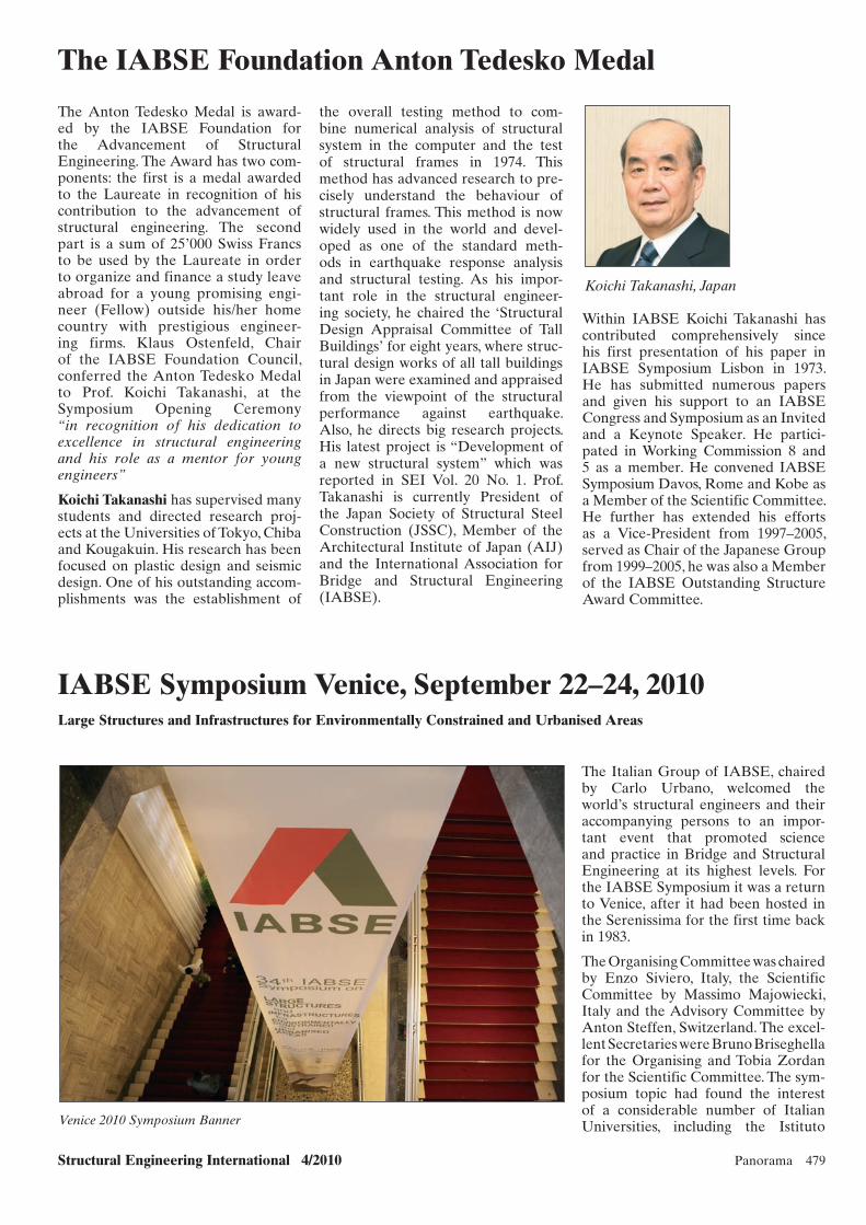
Structural Engineering International 4/2010 Panorama 479
IABSE Symposium Venice, September 22–24, 2010Large Structures and Infrastructures for Environmentally Constrained and Urbanised Areas
Koichi Takanashi, Japan
The Italian Group of IABSE, chaired by Carlo Urbano, welcomed the world’s structural engineers and their accompanying persons to an impor-tant event that promoted science and practice in Bridge and Structural Engineering at its highest levels. For the IABSE Symposium it was a return to Venice, after it had been hosted in the Serenissima for the first time back in 1983.
The Organising Committee was chaired by Enzo Siviero, Italy, the Scientific Committee by Massimo Majowiecki, Italy and the Advisory Committee by Anton Steffen, Switzerland. The excel-lent Secretaries were Bruno Briseghella for the Organising and Tobia Zordan for the Scientific Committee. The sym-posium topic had found the interest of a considerable number of Italian Universities, including the Istituto Venice 2010 Symposium Banner
The IABSE Foundation Anton Tedesko Medal
The Anton Tedesko Medal is award-ed by the IABSE Foundation for the Advancement of Structural Engineering. The Award has two com-ponents: the first is a medal awarded to the Laureate in recognition of his contribution to the advancement of structural engineering. The second part is a sum of 25’000 Swiss Francs to be used by the Laureate in order to organize and finance a study leave abroad for a young promising engi-neer (Fellow) outside his/her home country with prestigious engineer-ing firms. Klaus Ostenfeld, Chair of the IABSE Foundation Council, conferred the Anton Tedesko Medal to Prof. Koichi Takanashi, at the Symposium Opening Ceremony “in recognition of his dedication to excellence in structural engineering and his role as a mentor for young engineers”
Koichi Takanashi has supervised many students and directed research proj-ects at the Universities of Tokyo, Chiba and Kougakuin. His research has been focused on plastic design and seismic design. One of his outstanding accom-plishments was the establishment of
the overall testing method to com-bine numerical analysis of structural system in the computer and the test of structural frames in 1974. This method has advanced research to pre-cisely understand the behaviour of structural frames. This method is now widely used in the world and devel-oped as one of the standard meth-ods in earthquake response analysis and structural testing. As his impor-tant role in the structural engineer-ing society, he chaired the ‘Structural Design Appraisal Committee of Tall Buildings’ for eight years, where struc-tural design works of all tall buildings in Japan were examined and appraised from the viewpoint of the structural performance against earthquake. Also, he directs big research projects. His latest project is “Development of a new structural system” which was reported in SEI Vol. 20 No. 1. Prof. Takanashi is currently President of the Japan Society of Structural Steel Construction (JSSC), Member of the Architectural Institute of Japan (AIJ) and the International Association for Bridge and Structural Engineering (IABSE).
Within IABSE Koichi Takanashi has contributed comprehensively since his first presentation of his paper in IABSE Symposium Lisbon in 1973. He has submitted numerous papers and given his support to an IABSE Congress and Symposium as an Invited and a Keynote Speaker. He partici-pated in Working Commission 8 and 5 as a member. He convened IABSE Symposium Davos, Rome and Kobe as a Member of the Scientific Committee. He further has extended his efforts as a Vice-President from 1997–2005, served as Chair of the Japanese Group from 1999–2005, he was also a Member of the IABSE Outstanding Structure Award Committee.
Panorama.indd 479Panorama.indd 479 10/28/10 2:05 PM10/28/10 2:05 PM

480 Panorama Structural Engineering International 4/2010
Universitario di Architettura di Venezia and the Polictecnico di Milano as co-organisers, and the Universities of Naples, Rome, Trento and Turin as supporters.
The Palazzo del Casino and the Palazzo del Cinema, at the Lido in Venice served as venues. The atten-dance was high with almost 600 par-ticipants including accompanying persons. Out of 400 abstracts submit-ted to the theme ‘Large Structures and Infrastructures for Environmentally Constrained and Urbanised Areas’ the Scientific Committee selected 210 papers for oral presentation and some 150 for poster presentation, from 47 countries.
The Opening Ceremony
Welcome and Introductory Speeches were made by Carlo Urbano, Chair of the Italian Group of IABSE; Enzo Siviero, Chair of the Organising Committee; Antonio Paruzzolo rep-resenting Giorgio Orsoni, Mayor of Venice, Don Alberto representing Angelo Scola, Cardinal of Venice, and Jacques Combault, President IABSE, who subsequently presented the IABSE Awards 2010. Klaus Ostenfeld, Chair of the IABSE Foundation Council then conferred the IABSE Anton Tedesko Medal. Alberto Scotti gave an invited lecture on ‘The Venice Mose Project: an Holistic and Interdisciplinary Approach for Innovative Interventions’ and com-pleted the Ceremony.
Carlo Urbano, Chair, Italian Group of IABSE
Symposium Contents
Keynote Lectures, Presentations and Posters addressed the following main topics: Basis of Design; Infrastructure and Design as Meeting Point for Architecture and Engineering; Infra-structure Hazard and Safety Concepts; Management and Planning of Opera-tion and Maintenance; Ethics and Social Responsibility.
Keynote Lectures
• Giorgio Diana, Italy
The Messina Strait Bridge: Major Problems Affecting the Design
• Klaus Ostenfeld, Denmark
An Integrated Multidisciplinary App-roach to Design of Major Fixed Links
• Jiemin Ding, China
Recent Applications and Practices of Large-Span Steel Structures in China.
Invited Lectures were given on the following days of the Symposium: ‘Traceability Systems and Quality Systems: two Sides of same Coin’, by Corrado Baldi; ‘The Raising of the Buildings of the City of Venice for the Safeguard from the High Water’, by Enzo Siviero.
Symposium Report
Three Keynote Lectures and 375 contributions have been col-lected in the Symposium Report
and on a CD. The book (899 pages) and CD can be ordered at: www.iabse.org/publications/onlineshop/
BASAAR
Several IABSE Working Com-missions’ and Working Groups held their annual ‘BASAAR’ (Briefings About Structural Applications and Research) on Wednesday afternoon, September 22. The purpose of the BASAAR is to promote a lively dis-cussion about a topic predetermined by each Working Commission or Group. Following topics were pre-sented and discussed:
The Long-term Structural Performance (Life-Cycle Costs)by F. Biondini, Italy and M. Torkkelli Finland,(Co-ordinator M. SØderkvist, Finland, WC1)
Monitoring – Does it make Sense?by R. Geier, Austria and S. Nakamura, Japan,(Co-ordinator: R. Geier, Austria, WC 2).
Structural Safety Assessment of Concrete Structuresby J. McGormley, USA; M.Matsumoto Japan and C. Bob, Romania,(Co-ordinator: J. Tortorella, USA, WC 4).
The Long Term Issues Facing Structural Engineers in Environmentally Constrained Urban Areasby A. Boegle, Germany; A. Meyboom, Canada and F. Saad, Egypt,(Co-ordinator: W. Anderson, Canada, WC 5)
Integrating Sustainability into Structuresby J. Kanda, X. Ruan, China and J. Anderson, USA,(Co-ordinator: J. Kanda, Japan, WC 7)
Seismic Resistance of Structures – Lessons from Devastating Earthquakes (Chile, Mexico, Turkey, Haiti, Greece)by L.F. Fargier Gabaldon, USA; C. Mendez, Switzerland; M. Gercek, Turkey and D. Sonda, Italy,(Co-ordinator: St. Dritsos, WG 7)
In addition to the BASAAR a video presentation ‘Vibrations of the Volga Bridge in Volgograd, Russia’ was organised by S. Mozalev, Chair of the Russian Group of IABSE.
Panorama.indd 480Panorama.indd 480 10/28/10 2:05 PM10/28/10 2:05 PM
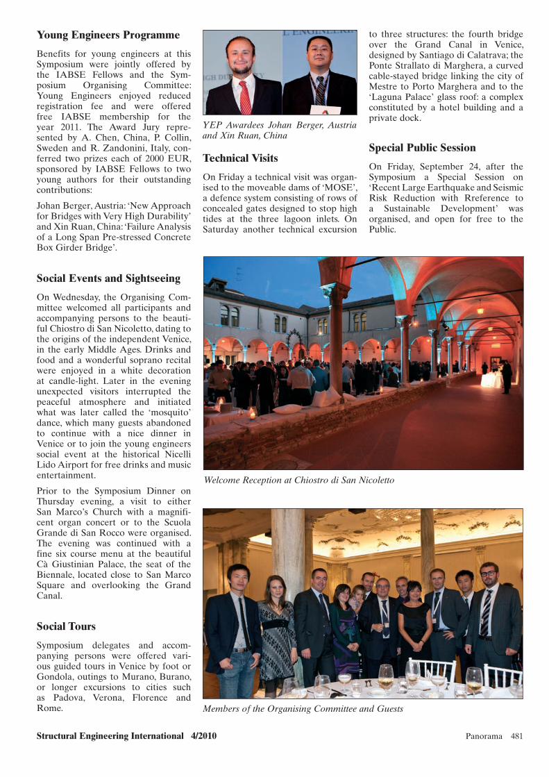
Structural Engineering International 4/2010 Panorama 481
to three structures: the fourth bridge over the Grand Canal in Venice, designed by Santiago di Calatrava; the Ponte Strallato di Marghera, a curved cable-stayed bridge linking the city of Mestre to Porto Marghera and to the ‘Laguna Palace’ glass roof: a complex constituted by a hotel building and a private dock.
Special Public Session
On Friday, September 24, after the Symposium a Special Session on ‘Recent Large Earthquake and Seismic Risk Reduction with Rreference to a Sustainable Development’ was organised, and open for free to the Public.
Young Engineers Programme
Benefits for young engineers at this Symposium were jointly offered by the IABSE Fellows and the Sym-posium Organising Committee: Young Engineers enjoyed reduced registration fee and were offered free IABSE membership for the year 2011. The Award Jury repre-sented by A. Chen, China, P. Collin, Sweden and R. Zandonini, Italy, con-ferred two prizes each of 2000 EUR, sponsored by IABSE Fellows to two young authors for their outstanding contributions:
Johan Berger, Austria: ‘New Ap proach for Bridges with Very High Durability’ and Xin Ruan, China: ‘Failure Analysis of a Long Span Pre-stressed Concrete Box Girder Bridge’.
Social Events and Sightseeing
On Wednesday, the Organising Com-mittee welcomed all participants and accompanying persons to the beauti-ful Chiostro di San Nicoletto, dating to the origins of the independent Venice, in the early Middle Ages. Drinks and food and a wonderful soprano recital were enjoyed in a white decoration at candle-light. Later in the evening unexpected visitors interrupted the peaceful atmosphere and initiated what was later called the ‘mosquito’ dance, which many guests abandoned to continue with a nice dinner in Venice or to join the young engineers social event at the historical Nicelli Lido Airport for free drinks and music entertainment.
Prior to the Symposium Dinner on Thursday evening, a visit to either San Marco’s Church with a magnifi-cent organ concert or to the Scuola Grande di San Rocco were organised. The evening was continued with a fine six course menu at the beautiful Cà Giustinian Palace, the seat of the Biennale, located close to San Marco Square and overlooking the Grand Canal.
Social Tours
Symposium delegates and accom-panying persons were offered vari-ous guided tours in Venice by foot or Gondola, outings to Murano, Burano, or longer excursions to cities such as Padova, Verona, Florence and Rome.
Welcome Reception at Chiostro di San Nicoletto
Members of the Organising Committee and Guests
Technical Visits
On Friday a technical visit was organ-ised to the moveable dams of ‘MOSE’, a defence system consisting of rows of concealed gates designed to stop high tides at the three lagoon inlets. On Saturday another technical excursion
YEP Awardees Johan Berger, Austria and Xin Ruan, China
Panorama.indd 481Panorama.indd 481 10/28/10 2:05 PM10/28/10 2:05 PM

482 Panorama Structural Engineering International 4/2010
Design and Construction Design for Dynamic Forces; Geo-environmental Issues and Administration; Main-tenance and Monitoring. Ref.: www.iabse-bd.org
Conference participants perceived the technological challenges that exist in Bangladesh for bridge construction and maintenance, but also recognised the necessity of having world class bridges in Bangladesh for the effective trans-portation not only within the country, but also within the Asian region. They identified the necessity of technology transfer, assimilation and formulation of a unified bridge code for the Asian countries in the coming years.
A volume with 594 pages has been published, for more information, please contact A.F.M. Saiful Amin: [email protected]
at the Opening Ceremony, and two Honorable Ministers responsible for the Ministries of Communication, Science and Information Technology, Government of Bangladesh, attended the Conference Dinner and Closing Ceremonies of the conference. The presence of Muhammad Yunus, Nobel Laureate for Peace in the Conference Dinner inspired participants greatly. Experts, professionals and academi-cians from Asia, Europe, Australia and the North America discussed the issues of Bridge Engineering and its further development for the benefit of the people and community. The total number of registration to the confer-ence was 338.
Six Keynote addresses were sup-ported by 56 technical papers from 11 countries and four continents. Bridge engineering themes were on: History and Planning Materials; Analysis;
Md. Yunus (right), Nobel Laureate for Peace. From left: H. Mutsuyoshi, Saitama Univ.; M. Nagai, Nagoaka Univ. of Tech. Japan; K. Wheeler, Maunsell AECOM
Left to right: M. A. Sobhan (Chair, Bangladesh IABSE Group); Md. Yunus (Nobel Laureate); A.F.M. Saiful Amin (General Secretary, Bangladesh IABSE Group)
Dhaka Conference ‘Advances in Bridge Engineering-II’ Organised by the Bangladesh Group of IABSE and JSCE Steel Structures Committee, Japan
The Dhaka Conference on ‘Advances in Bridge Engineering-II’ held from August 8–10, 2010, was a great suc-cess. It was jointly organised by the new Bangladesh Group of IABSE and JSCE Steel Structures Committee, in Association with the Roads and Highways Department Government of Bangladesh and the Institu-tion of Engineers, Bangladesh and co-organisers from the Bangladesh Sections of the American Society of Civil Engineers and Institution of Civil Engineers, UK. One of the major aspects of this conference was bringing major professional societies and bodies working in the region together to achieve an effec-tive collaboration and partnership in future.
B.C. Roy, Vice-President of IABSE presented a message on behalf of IABSE President, Jacques Combault
Panorama.indd 482Panorama.indd 482 10/28/10 2:05 PM10/28/10 2:05 PM

Max-Paul-Straße 188525 Dürmentingen / Germanywww.paul.eu
Phone: +49 (0) 73 71 / 5 00 - 0Fax: +49 (0) 73 71 / 5 00 - 111Mail: [email protected]
Maschinenfabrik GmbH & Co. KG
The experts in Prestressed Concrete Technology.
PAUL suppliesPrestressing installations incl. planning work• Anchor grips• Prestressing machinery• (single-/multi-stressing jacks)Strand pushing and cutting equipment• Automatic prestressing machines for railway sleepers• Prestressing equipment for bridge construction• (prestressing cables and stay cables)
A matter of confidence.
Stressing of stay cables
Schrägseile, A4, de-en.indd 1Schrägseile, A4, de-en.indd 1 14.12.2009 13:51:0814.12.2009 13:51:08

Brilliant Slide
Maurer Söhne GmbH & Co. KGFrankfurter Ring 193, 80807 Munich/GermanyPhone +49 89 32394–0Fax +49 89 32394–[email protected]
MAURER Sliding Alloy
MSA® – New for
spherical bearings!
New alloy MSA® for bearings in bridge and building structures. Shining – special treatment of
the surface for reduced sliding resistance and abrasive wear
Resistant to agressive industrial air – especially against fluorine and chlorine
Superior corrosion resistance Better economic efficiency Longer lifetime Approved by the construction
authorities (AbZ Z-16.4-436)
Our Product Range Maurer expansion Joints Maurer Structural Bearings Maurer Seismic Protection Systems Maurer Vibration Control Systems Maurer Monitoring of Structures
Anz_MSA_A4_4c•••eng.indd 1 13.10.10 13:53