Seat Valves T-smart - GEA engineering for a better world · Seat valves T-smart Seat valves T-smart...
94
Seat Valves T-smart Product Group Flow Components Catalog 2018
Transcript of Seat Valves T-smart - GEA engineering for a better world · Seat valves T-smart Seat valves T-smart...

Seat Valves T-smartProduct Group Flow ComponentsCatalog 2018


· 3
GEA
Legal notice
Publication date: August 2018
The publication of specifications, technical data and information in written or electronic form does not release the user from the responsibility of checking for themselves all products delivered by us for suitability for the application(s) intended. These may be subject to change without prior notification. Errors and printing errors excepted – we assume no liability for the correctness of specifications given.
The general terms and conditions of delivery apply.
All rights reserved – copyright on all contents. The ® symbol in this catalog identifies a trademark registered in certain countries.
GEA Tuchenhagen GmbHAm Industriepark 2 – 10, 21514 Büchen, GermanyRegistered office: Büchen, Court of Registration: Lübeck, HRB 836 SBManagement office: Tobias Dieckmann, Michael Wulle, Oliver HegehoferSales tax identification number: DE 812589019

4 ·
GEA
Pages
Introduction to GEA Flow Components .......................................................................................................................................................................6
Seat Valves T-smartIntroduction to Seat Valves T-smart ..............................................................................................................................................................................8
Overview ................................................................................................................................................................................................................................10
Technical data ......................................................................................................................................................................................................................12
Certificates ........................................................................................................................................................................................................................... 15
Valve Selection Matrix .......................................................................................................................................................................................................16
Single-seat ValvesOverview – Shut-off Valves .............................................................................................................................................................................................18
Type 1007 ..............................................................................................................................................................................................................................20
Type 1003 ............................................................................................................................................................................................................................. 22
Overview – Divert Valves .................................................................................................................................................................................................24
Type 2017 ..............................................................................................................................................................................................................................26
Type 2027 ..............................................................................................................................................................................................................................28
Mixproof Shut-off ValvesOverview – Mixproof Double-seat Valves ................................................................................................................................................................. 30
Type 3022 .............................................................................................................................................................................................................................32
Type 3011 ............................................................................................................................................................................................................................. 34
Type 3012 ............................................................................................................................................................................................................................. 36
Type 3021 ............................................................................................................................................................................................................................. 38
Overview – Double-seal Valves ..................................................................................................................................................................................... 40
Type 5007 ..............................................................................................................................................................................................................................42
Type 5003 ............................................................................................................................................................................................................................ 44
Tank Bottom ValvesOverview – Single-seat Bottom Valves ...................................................................................................................................................................... 46
Type 4001 ............................................................................................................................................................................................................................. 48
Type 4002 ............................................................................................................................................................................................................................ 50
Contents

· 5
GEA
Pages
Spare PartsSeal Kits ..................................................................................................................................................................................................................................52
Spare Part Kits..................................................................................................................................................................................................................... 54
Tools ....................................................................................................................................................................................................................................... 56
Control and Feedback SystemsOverview ............................................................................................................................................................................................................................... 58
Certificates ........................................................................................................................................................................................................................... 59
Selection Matrix T.VIS® .................................................................................................................................................................................................... 60
T.VIS® M-15 .......................................................................................................................................................................................................................... 62
T.VIS® A-15 ........................................................................................................................................................................................................................... 68
Connection 0, INA ............................................................................................................................................................................................................ 72
Proximity Switches ..............................................................................................................................................................................................................74
Adaptation ............................................................................................................................................................................................................................75
IP Protection Classes .........................................................................................................................................................................................................76
Semi-automatic Setup ...................................................................................................................................................................................................... 77
Connection Screw Fitting ................................................................................................................................................................................................78
Interface Types .....................................................................................................................................................................................................................79
AppendixComposition of the Order Code .................................................................................................................................................................................. 81
Complete Order Code ...................................................................................................................................................................................................... 82
Description of Certificates .............................................................................................................................................................................................. 86
Abbreviations and Terms ................................................................................................................................................................................................ 87
CAD Files .............................................................................................................................................................................................................................. 91
General Sales Terms and Conditions of Delivery ................................................................................................................................................... 92
Contents

6 ·
GEA
GEA Group Aktiengesellschaft GEA is one of the largest suppliers of process technology for the food industry and for a wide range of other industries. As an international technology group, the company focuses on world-leading process solutions and components for sophisticated production processes.
Regardless of the application – for our customers product quality and profitability are what matters. This is what GEA Flow Components is known for. Our engineers are specialists in everything that flows.
GEA Flow Components GEA offers well-engineered process components and services to ensure smooth production processes in the treatment of liquid products. We develop and produce a comprehensive product range that includes valve technology for all hygienic classes (Hygienic, UltraClean, Aseptic), hygienic pumps and cleaning technology.
GEA Flow Components products and services are available around the world through the international GEA network.
Around one quarter of the milk processed is handled by GEA equipment
Roughly every second liter of beer is brewed using GEA equipment and solutions
Approx. one in three instant coffee lines has been built by GEA
Introduction to GEA Flow Components

· 7
GEA
Cleaning Technology Index, orbital, rotating and static cleaners in a complete range, developed with special emphasis on saving valuable resources in the cleaning process.
Hygienic Pump Technology A great variety of Hygienic pumps with sensibly rated high efficiency motors and carefully designed flow paths, driving economic efficiency and sustainable operation.
Hygienic Valve Technology A complete range of economically designed Hygienic valves for complex tasks as well as basic functions, helping producers to achieve high product quality and efficiency.
Aseptic Valve Technology UltraClean and Aseptic valves are suitable for production processes which require a higher safety protection against contamination from the environment and thus warrant microbial stability of the product over the whole process.
State-of-the-art hygienic design
GEA Flow Components meet the highest hygienic standards where required, such as EHEDG and 3-A standards.
Hygienic valves and components from GEA form the core component of matrix-piped process plants.
When it comes to sterile applications, GEA offers both Ultra-Clean and Aseptic valves and systems. The hermetic sealing of the product area provides a maximum level of process line isolation and thus contributes to process and product safety.
The hygienic pump range from GEA includes centrifugal pumps (single-stage, multi-stage and self-priming), as well as rotary lobe pumps.
GEA cleaning devices – whether index, orbital, rotary or static – achieve optimum cleaning results in multiple industries. GEA product recovery systems help to recover valuable products and reduce both waste disposal costs as well as water and detergent consumption.
Applications
• Beverage – Beer, juice, smoothie products …
• Dairy – Milk, yoghurt, cheese …
• Food – Sauces & cremes, ketchup, mayonnaise …
• Pharma/Biotech – Pharmaceuticals, biotechnology products, cosmetics & health care …
• Chemicals – Fine chemicals, bulk chemicals, cleaning chemicals …
• Dairy farming – Raw milk processing …
Introduction to GEA Flow Components

8 ·
GEA
Your investment pays off GEA Tuchenhagen seat valves of the T-smart series can save you considerable costs. The compact actuators and efficient control technology ensure low energy consumption.
The design of the valves without dead space satisfies the most exacting hygienic requirements and prevents unnecessary product losses. Long-lived seals help reduce operating costs. These design features reduce the consumption of valuable energy, water and cleaning media, as well as the time and staff expenditure for cleaning and maintenance.
The ROI on your investment in innovative process technology from GEA Tuchenhagen will be quickly noticeable.
GEA Tuchenhagen products are based on future-oriented company and product design principles that include an obligation to economic viability, sustainability and service.
Seat Valves T-smart
Introduction to Seat Valves T-smart
Economical
Higher product quality
Reduced consumption of energy, water and cleaning media
Reduced time and personnel costs for maintenance and cleaning

· 9
GEA
You score points with environmental protection Lower consumption of energy, water and chemicals means less pollution for the climate and environment. GEA Tuchenhagen meets these requirements by complying with binding international standards.
As a user of GEA Tuchenhagen products, you benefit from proven environmentally-friendly production processes, as well as the high standards for hygienic processing and care of your products. This makes a significant contribution to protecting the global environment and climate.
With our products, you show how important sustainable working processes are to you and that you take responsibility for future generations!
Our support is your gain In addition to our product range, you can also make use of the individualized engineering support from GEA Tuchenhagen. Even before you have started using our products, this support provides you with extensive digital tools – from technical drawings to 3-D models.
The individualized service concepts from GEA Tuchenhagen ensure that maintenance work is conducted with the lowest amount of production downtime possible.
We look forward to creating and customizing a maintenance plan for you.
Seat Valves T-smart
Introduction to Seat Valves T-smart
Sustainable
Lower climate and environmental impact
Sustainable, environmentally friendly production processes
High standards for hygienic processing and care of products
Service-oriented
Individual engineering support
Shortest possible interruptions of production
Individual service concept

10 ·
GEA
The compact seat valves of the T-smart series set new standards for high power with low space demands. Due to their small build, the valves have a low weight, which considerably simplifies operation. Low operation, maintenance and servicing costs contribute to high system productivity.
The T-smart valve series offers valves in standard forms that are often used with optional equipment parts and comprehensive accessories. All necessary versions in housing spaces and control top types are available.
Like all GEA components, the T-smart series corresponds to the highest quality demands and seamlessly merges with the outstanding product range “Made by GEA Tuchenhagen”.
Seat valves T-smart
Seat valves T-smart are subject to production certified acc. to DIN EN ISO 9001:2000 without exception and correspond to the requirements of the European Hygienic Engineering and Design Group (EHEDG).
The T-smart valves have not only been tested for precise compliance with the guidelines named, but also have passed an independent and a standardized cleaning test for their suitability with easy and efficient cleaning.
Seat Valves T-smart
Overview
Small and compact
Low weight
Maintenance-friendly
Low servicing costs
Hygienic design
Low risk of contaminating the end product
Maximum efficiency in cleaning
Lower CIP costs

· 11
GEA
The bayonet lock
The innovative bayonet lock is the perfect interface between the valve lantern and the housings. In connection with pre-tension-free radial seals, the benefit of this lock is that the user does not need any special tools to (dis)assemble the valve insert. Clamping connections were not used at all. The bayonet lock meets all necessary safety requirements: A safety screw connection prevents inadvertent twisting/opening of the valve; the two interlocking metal surfaces of the bayonet lock additionally secure against opening of the valve under product pressure.
Actuator
The actuators of the T-smart seat valve series are available spring-to-open and spring-to-close. This must be indicated clearly by the article number when ordering, since the actuator cannot be turned subsequently to change the effect.
The design of T-smart seat valves has been standardized as well. The lift functions for both valve discs are integrated into the actuator as standard.
GEA Tuchenhagen utilizes its known high quality demands and always maintenance-free designs with its actuators of the T-smart seat valve series. This ensures maximum safety for the user, since the actuators do not have to be opened with the present spring forces for maintenance purposes.
Valve housing
The housings of the T-smart seat valve series are delivered standardized with an inner surface quality of Ra ≤ 0.8 µm and a ground outer surface. This corresponds to the required surface qualities of the essential standards in the valve design (e.g. EHEDG).
For single-seat valves (shut-off, divert and tank bottom valves), in-line and angle housings (L- and T-housings) are available as standard versions. Different housing combinations can be chosen for double-seat valves.
For all T-smart seat valves, the housing combinations are designed as firmly connected housings; therefore, the correct angle between the housings must be ensured when you place the order. The different angles are determined by the article numbers and must be indicated clearly in the order code.
Seals
The sealing of the valve discs takes place by maintenance-friendly O-rings, available in material EPDM. Particularly narrow production tolerances for these O-rings ensure hygienically proper sealing under the different process conditions.
To reduce necessary spare parts inventories at the customer's site, seals of the same kind are re-used according to valve type and rated widths, so that the number of required sealings is minimal.
Valve information system T.VIS®
Control tops of the T.VIS® generation are available in different versions for the T-smart seat valves, under which the proper selection is made depending on customer needs. The T.VIS® control tops are individually optimized for each customer, independently of whether the proven sensor technology of the T.VIS® M-15 or the state-of-the-art path measuring technology of the T.VIS® A-15 are used.
Seat Valves T-smart
Overview
T-smart benefits
Made by GEA Tuchenhagen
EHEDG-certified
Seat Valves T-smart
Reliable and simple maintenance
Hygienic and space-saving design
Suitable material selection for metal components and seals
High surface quality of components in contact and not in contact with the product
Self draining system of the housings without domes and sumps
GEA Tuchenhagen valve technology

12 ·
GEA
Pipe classes
Standard VARIVENT® valve housings are supplied with welding ends, although the valves can be delivered with various connection fittings as an option (see section 8).
The dimensions of the welding ends comply with the following standards:
Metric
DN Outside diamter acc. to DIN 11866, series A
10 13.0 × 1.50
15 19.0 × 1.50
25 29.0 × 1.50
40 41.0 × 1.50
50 53.0 × 1.50
65 70.0 × 2.00
80 85.0 × 2.00
100 104.0 × 2.00
125 129.0 × 2.00
150 154.0 × 2.00
Surfaces
Surfaces in contact with the product are designed in Ra ≤ 0.8 μm as standard.
Materials
Components in contact with the product are produced from AISI 316 L, while those not in contact with the product are made from AISI 304.
For detailed information about the properties of the materials, refer to the material properties table.
Material test certificates
Optionally, the valve housings and product wetted parts can be supplied with a test report 2.2 or an inspection certificate 3.1 acc. to EN 10204.
If 3.1 inspection certificates are required, please notify us ofthis when you place the order.
Seal materials
Seals in contact with the product are EPDM. NBR material is used for seals not in contact with the product.
The mixing constituents of our seal materials are contained in the FDA “White List” and are in accordance with “FOOD and DRUG” (FDA) guidelines 21 CFR Part 177.2600 or 21 CFR 177.1550: “Rubber articles intended for repeated use”.
The resistance of the seal material depends on the nature and temperature of the product being transported. The contact time can negatively affect the service life of seals.
For detailed information about the properties of the seal materials, refer to the seal material properties table.
Operating pressure
The valves can be used up to a vacuum of –0.95 bar and are designed up to a product pressure of 5 bar (NC: DN 80–DN 100, OD 4") or 6 bar (NC: DN 25–DN 65, OD 1"–OD 3" / NO: DN 25–DN 100, OD 1"–OD 4").
Seat Valves T-smart
Technical Data

· 13
GEA
Ambient conditions
Ambient temperatures
VARIVENT® / ECOVENT®
(with connection 0)
0 °C to 45 °C
32 °F to 113 °F
Proximity switches−20 °C to 80 °C
−4 °F to 176 °F
The valves can also be used outdoors. However, in these application areas they must be protected against icing, or else de-iced before switching or lifting. In addition, the particularrequirements on the control and feedback system must betaken into account in this case.
The product or operating temperature depends on the seal material and can be seen in the seal material properties table.
T-smart seat valves must be installed without stresses. Lateral forces such as expansion of the pipelines due to heat cannot be compensated in the valve; as a result valve damage is possible. In such cases, we recommend taking measures to compensate for the expansion, such as by using the VARICOMP® expansion compensator.
The required clearance for installing and removing a T-smart seat valve is specified in the particular technical data and dimensional sheet.
Air supply
The valve actuators are configured for operation with min.4 bar and max. 8 bar air pressure. The standard actuator sizesare configured for an air supply pressure of min. 6 bar (with aproduct pressure of 5 bar). The quality of the air supply mustmeet the requirements of ISO 8573-1:2010.
ISO 8573-1:2010
Solid content Quality class 6
Particle size max. 5 μm
Particle density max. 5 mg/m³
Water content Quality class 4
Max. dew point 3 °C
A correspondingly different dew point is required for applications at high altitude or with low ambi-ent temperatures.
Oil content Quality class 3
Max. 1 mg oil per 1 m³ air, preferably oil-free
Actuator types
Seat valves T-smart are delivered with a pneumatic actuator. They are configured for long-term operation, and are maintenance-free.
Feedback
In the control top See section 7: Control and feedback systems
Proximity switch holder on the actuatorThe proximity switch holder M12×1 (INA) makes it possible to use feedback sensors above the actuator. The proximity switch holder has prepared M12×1 holes which allow the sensors to be set optimally. A direct connection to the controller provides the feedback on the valve position (see section 7: Control and Feedback Systems).
Recommended flow direction
If possible, the valves should close against the flow direction in order to avoid water hammer.
Seat Valves T-smart
Technical Data

14 ·
GEA Seat Valves T-smart
Main alloy elements in % by mass
Material number
Short name Similar materials PREN*Cr
(Chrome)Ni
(Nickel)
Mo (Molybde-
num)
C max. (Carbon)
AISI 304 X5CrNi18-10 1.4301 BS 304S15 SS2332 18 17.5 – 19.5 8.0 – 10.5 – 0.07
AISI 316L X2 CrNiMo 17-12-2 1.4404 BS 316S11 SS2348 25 16.5 – 18.5 10.0 – 13.0 2.0 – 2.5 0.03
Material properties
* Pitting Resistance Equivalent Number = % Cr + 3.3 × (% Mo + 0.5 W) + 20 N
Seal material properties
Other applications on request * Depending on the installation situation ** Inorganic acids include hydrochloric acid, nitric acid, sulphuric acid
Seal material EPDM
General application temperature*−40 to 135 °C−40 to 275 °F
Medium ConcentrationAt permitted
operating temperature
Alkali
≤ 3 % up to 80 °C +
≤ 5 % up to 40 °C +
≤ 5 % up to 80 °C +
> 5 %
Inorganic acid**
≤ 3 % up to 80 °C +
≤ 5 % up to 80 °C
> 5 % up to 100 °C −
Water up to 100 °C +
Steam up to 135 °C +
Steam, approx. 30 min
up to 150 °C +
Hydrocarbons/ fuels
−
Products containing grease
≤ 35 % +
> 35 % −
Oils −
+ = Good resistance = Reduced service life
− = Not resistant
Technical Data

· 15
GEA
The certificates listed here are valid for corresponding GEA valves and components. Valves conforming to the requirements of the Eu-ropean Hygienic Engineering and Design Group (EHEDG) as well as 3-A Sanitary Standards, Inc. (3-A SSI) are available for numerous fields of application.
EHEDG certificates apply only to the specific valve type as listed. However, they can be transferred to other valve types, owing to identical housing designs and sealing geometries.
Moreover, independent, standardized tests have confirmed the efficient, problem-free cleanability of numerous valves – for optimum safety and economic gain.
Certificates
Standard certificates Optional certificates
Inde
x
CE
EHED
G
FDA
EG N
o.
1935
/200
4
USP
C
lass
VI
T-sm
art
1 Shutt-off valve type 1007 • • • • •
1 Shutt-off valve type 1003 • • • • •
2 Divert valve type 2017 • • • • •
2 Divert valve type 2027 • • • • •
3 Double-seat valve type 3022 • • • • •
3 Double-seat valve type 3011 • • • • •
3 Double-seat valvetype 3012 • • • • •
3 Double-seat valve type3021 • • • • •
4 Double-seal valve type 5007 • • • • •
4 Double-seal valve type 5003 • • • • •
5 Single-seat bottom valve type 4001 • • • • •
5 Single-seat bottom valve type 4002 • • • • •
Seat Valves T-smart

16 ·
GEA
Seat Valves T-smart
Catalogs Cleaning Technology
Cleaning Technology
Catalogs Aseptic Valve Technology
Aseptic Valve Technology
Catalogs Hygienic Pump Technology
Hygienic Centrifugal Pumps
Catalogs Hygienic Valve Technology
Hygienic Valves VARIVENT® and ECOVENT®
Butterfly Valves T-smart
Seat Valves T-smart
Hygienic Valves and Components
Valve Selection Matrix

· 17
Single-seat valves
Tank bottom valves
Mixproof seat valves
Shut-off valves
Divert valves
Mixproof Shut-off valves
Double-seal valves
Single-seat bottom valves
Spare parts
Control and feedback systems
Seat Valves T-smart
1
2
3
4
5
6
7

18 ·
GEA
T-smart shut-off valves – Series 1000
T-smart single-seat valves of the 1000 series are used for simple shut-off in hygienic applications. The valves are characterized by their ease of operation and flexibility.
Function of the valve
In the simple shut-off, there is only one seal in the one-piece valve disc separating the pipelines from one another. This means liquid can pass from one pipeline to the other in the event of a seal defect. For this reason, shut-off valves of the 1000 series are not suitable for separating incompatible fluids.
Application examples
In practical use, these valves are used, for example, as emptying/drainage valves or for shutting off a bypass line. Frequently, these types of valve are also used as dosing valves.
Single-seat Valves
Overview Shut-off Valves
Special features
EHEDG-certified hygienic configuration
Small and compact
Maintenance-friendly

· 19
GEA
1
T-smart benefits
The valve series T-smart offers valves in standard forms that are used often and dispenses with optional equipment parts and comprehensive accessories.
The compact design and the philosophy of the hygienic valves leads to an economical solutions for standard requirements. All necessary versions in terms of housing shapes and control top types are available.
Housing combinations
Two housing designs are available as standard in the T-smart shut-off valve 1000 series.
Recommended flow direction
To avoid water hammers when closing one path while the product is flowing, T-smart shut-off valves 1000 should be switched against the flow direction of the product, if possible. Single-seat valve type 1007
Single-seat valve type 1003
Single-seat Valves
Overview Shut-off Valves
Sizes T-smart 1000
DN 25 – DN 100
OD 1" – OD 4"

20 ·
GEA
Technical data of the standard version
Recommended flow direction Contrary to the flow direction of the product
Material in contact with the product AISI 316L
Material not in contact with the product AISI 304
Seal material in contact with the product EPDM
Ambient temperature 0 to 45 °C
Air supply pressure Min. 6 bar, max. 8 bar
Max. product pressure DN 25 – DN 65
OD 1" – OD 3"Max. 6 bar
DN 80 – DN 100
OD 4"Max. 5 bar / max. 6 bar*
Surface in contact with the product Ra ≤ 0.8 μm
Surface not in contact with the product Metal blank
Control and feedback system Connection 0 (without control top)
Actuator type Pneumatic actuator air/spring
Connection fittings Welding end
Certificates
Pipe Housing Actuator Dimensions Valve
Nominal width
Ø [mm]
A [mm]
C [mm]
Ø D [mm]
H1[mm]
H2 [mm]
X[mm]
Stroke S[mm]
Particle size[mm]
Weight [kg]
DN 25 29,0 × 1,50 34.0 90 109 117.5 281.5 165 18 9 4.5
DN 40 41,0 × 1,50 37.0 90 109 130.5 294.5 190 25 16 4.5
DN 50 53,0 × 1,50 41.0 90 109 136.5 300.5 210 25 16 4.5
DN 65 70,0 × 2,00 50.0 125 135 / 170* 154.5 318.5 245 33 24 8.5
DN 80 85,0 × 2,00 65.5 125 170 180.0 344.0 285 41 32 12.5
DN 100 104,0 × 2,00 71.0 125 170 189.5 353.5 315 41 32 13.0
OD 1" 25,4 × 1,65 33.0 90 109 115.5 279.5 160 18 9 4.5
OD 1 ½" 38,1 × 1,65 36.5 90 109 129.0 293.0 185 25 16 4.5
OD 2" 50,8 × 1,65 42.0 90 109 135.5 299.5 205 25 16 4.5
OD 2 ½" 63,5 × 1,65 49.0 125 135 / 170* 151.5 315.5 235 33 24 8.5
OD 3" 76,2 × 1,65 52.5 125 135 / 170* 158.0 322.0 255 33 24 8.5
OD 4" 101,6 × 2,11 72.0 125 170 188.5 352.5 310 41 32 13.0
* The left value refers to the closed fail-safe position of the valve, the right one to the open non-actuated position (see position 5 in the order code).
Type 1007
Single-seat Valves
Shut-off Valves

· 21
GEA
1
Position Description of the order code for the standard version
1 Valve type
1 Shut-off valve
2 Housing combinations
007
L
3 Nominal width standard
0 OD 1 DN
4 Nominal width
100 OD 1" 025 DN 25
150 OD 1 ½" 040 DN 40
200 OD 2" 050 DN 50
250 OD 2 ½" 065 DN 65
300 OD 3" 080 DN 80
400 OD 4" 100 DN 100
5 Non-actuated position
0 Closed
1 Opened
6 Air connection
0 Without
1 Metric
2 Inch
7 Port orientation top
0 0°
8 Air support
0 Without
9 Seal material
0 EPDM
10 Port orientation bottom
0 No connection
11 Connection fittings
0 Welding end
1 Tri-clamp
12 Certificates
0 Without
1 Test report 2.2
2 Inspection certificate 3.1
3 Certificates 2.2 and 3.1
Position 1 2 3 4 5 6 7 8 9 10 11 12Code for control and feedback systems, see section 7
Code 1 007 - - 0 0 - 0 0 +
The code is composed as follows, depending on the chosen configuration:
Type 1007
Single-seat Valves
Shut-off Valves

22 ·
GEA
Technical data of the standard version
Recommended flow direction Contrary to the flow direction of the product
Material in contact with the product AISI 316L
Material not in contact with the product AISI 304
Seal material in contact with the product EPDM
Ambient temperature 0 to 45 °C
Air supply pressure Min. 6 bar, max. 8 bar
Max. product pressure DN 25 – DN 65
OD 1" – OD 3"Max. 6 bar
DN 80 – DN 100
OD 4"Max. 5 bar / max. 6 bar*
Surface in contact with the product Ra ≤ 0.8 μm
Surface not in contact with the product Metal blank
Control and feedback system Connection 0 (without control top)
Actuator type Pneumatic actuator air/spring
Connection fittings Welding end
Certificates
Pipe Housing Actuator Dimensions Valve
Nominal width
Ø [mm]
A [mm]
C [mm]
Ø D [mm]
H1[mm]
H2 [mm]
X[mm]
Stroke S[mm]
Particle size[mm]
Weight [kg]
DN 25 29,0 × 1,50 34.0 90 109 117.5 281.5 165 18 9 4.5
DN 40 41,0 × 1,50 37.0 90 109 130.5 294.5 190 25 16 4.5
DN 50 53,0 × 1,50 41.0 90 109 136.5 300.5 210 25 16 4.5
DN 65 70,0 × 2,00 50.0 125 135 / 170* 154.5 318.5 245 33 24 8.5
DN 80 85,0 × 2,00 65.5 125 170 180.0 344.0 285 41 32 12.5
DN 100 104,0 × 2,00 71.0 125 170 189.5 353.5 315 41 32 13.0
OD 1" 25,4 × 1,65 33.0 90 109 115.5 279.5 160 18 9 4.5
OD 1 ½" 38,1 × 1,65 36.5 90 109 129.0 293.0 185 25 16 4.5
OD 2" 50,8 × 1,65 42.0 90 109 135.5 299.5 205 25 16 4.5
OD 2 ½" 63,5 × 1,65 49.0 125 135 / 170* 151.5 315.5 235 33 24 8.5
OD 3" 76,2 × 1,65 52.5 125 135 / 170* 158.0 322.0 255 33 24 8.5
OD 4" 101,6 × 2,11 72.0 125 170 188.5 352.5 310 41 32 13.0
* The left value refers to the closed fail-safe position of the valve, the right one to the open non-actuated position (see position 5 in the order code).
Type 1003
Single-seat Valves
Shut-off Valves

· 23
GEA
1
Position Description of the order code for the standard version
1 Valve type
1 Shut-off valve
2 Housing combinations
003
T
3 Nominal width standard
0 OD 1 DN
4 Nominal width
100 OD 1" 025 DN 25
150 OD 1 ½" 040 DN 40
200 OD 2" 050 DN 50
250 OD 2 ½" 065 DN 65
300 OD 3" 080 DN 80
400 OD 4" 100 DN 100
5 Non-actuated position
0 Closed
1 Opened
6 Air connection
0 Without
1 Metric
2 Inch
7 Port orientation top
0 0°
8 Air support
0 Without
9 Seal material
0 EPDM
10 Port orientation bottom
0 No connection
11 Connection fittings
0 Welding end
1 Tri-clamp
12 Certificates
0 Without
1 Test report 2.2
2 Inspection certificate 3.1
3 Certificates 2.2 and 3.1
Position 1 2 3 4 5 6 7 8 9 10 11 12Code for control and feedback systems, see section 7
Code 1 003 - - 0 0 - 0 0 +
The code is composed as follows, depending on the chosen configuration:
Type 1003
Single-seat Valves
Shut-off Valves

24 ·
GEA
T-smart divert valve – Series 2000
T-smart divert valves are used for simple divert functions in hygienic applications. The valves are characterized by their ease of operation. The individual variants are designed for different flow directions.
Function of the valve
In divert valves, there is only one seal for each switching position in the valve disc separating the particular pipelines from one another. This means liquid can pass from one pipeline to the other in the event of a seal defect. For this reason, divert valves of the T-smart series are not suitable for separating incompatible fluids.
Application examples
In practice, these valves are frequently used in CIP supply and return lines. A typical use case is found at the end of a valve block as divert valve between the process line and drain, e.g. during pushing out.
Single-seat Valves
Overview Divert Valves
Special features
EHEDG-certified hygienic configuration
Small and compact
Maintenance-friendly

2
· 25
GEA
T-smart benefits
The valve series T-smart offers valves in standard forms that are used often and dispenses with optional equipment parts and comprehensive accessories.
The compact design and the philosophy of the hygienic valves leads to an economical solution for standard requirements. All necessary versions in terms of housing shapes and control top types are available.
Housing combinations
T-smart divert valves are available as the standard in two housing versions.
Recommended flow direction
To avoid water hammers when closing one path while the product is flowing, T-smart divert valves 2000 should be switched against the flow direction of the product, if possible.
Single-seat valve type 2017
Single-seat valve type 2027
Single-seat Valves
Overview Divert Valves
2
Sizes T-smart 2000
DN 25 – DN 100
OD 1" – OD 4"

26 ·
GEA
Technical data of the standard version
Recommended flow direction Contrary to the flow direction of the product
Material in contact with the product AISI 316L
Material not in contact with the product AISI 304
Seal material in contact with the product EPDM
Ambient temperature 0 to 45 °C
Air supply pressure Min. 6 bar, max. 8 bar
Max. product pressure DN 25 – DN 65
OD 1" – OD 3"Max. 6 bar
DN 80 – DN 100
OD 4"Max. 5 bar / max. 6 bar*
Surface in contact with the product Ra ≤ 0.8 μm
Surface not in contact with the product Metal blank
Control and feedback system Connection 0 (without control top)
Actuator type Pneumatic actuator air/spring
Connection fittings Welding end
Certificates
* The left value refers to the closed fail-safe position of the valve, the right one to the open non-actuated position (see position 5 in the order code).
Pipe Housing Actuator Dimensions Valve
Nominal width
Ø [mm]
A [mm]
C [mm]
K [mm]
Ø D1 [mm]
H1[mm]
H2 [mm]
X[mm]
Stroke S[mm]
Particle size[mm]
Weight [kg]
DN 25 29,0 × 1,50 34.0 90 34.0 109 117.5 281.5 199 18 6 5.5
DN 40 41,0 × 1,50 46.0 90 37.0 109 130.5 294.5 236 25 16 5.5
DN 50 53,0 × 1,50 58.0 90 41.0 109 136.5 300.5 268 25 16 6.0
DN 65 70,0 × 2,00 74.0 125 53.0 135/170* 154.5 318.5 319 33 24 12.0
DN 80 85,0 × 2,00 89.0 125 65.5 170 180.0 344.0 374 41 32 16.5
DN 100 104,0 × 2,00 108.0 125 71.0 170 189.5 353.5 423 41 32 17.0
OD 1" 25,4 × 1,65 30.0 90 33.0 109 115.5 279.5 190 18 4 5.5
OD 1 ½" 38,1 × 1,65 43.0 90 36.5 109 129.0 293.0 228 25 16 5.5
OD 2" 50,8 × 1,65 55.5 90 42.0 109 135.5 299.5 261 25 16 6.0
OD 2 ½" 63,5 × 1,65 68.0 125 50.0 135/170* 151.5 315.5 303 33 24 11.5
OD 3" 76,2 × 1,65 81.0 125 52.5 135/170* 158.0 322.0 336 33 24 12.0
OD 4" 101,6 × 2,11 105.5 125 72.0 170 188.5 352.5 416 41 32 16.5
Type 2017
Single-seat Valves
Divert Valves

2
· 27
GEA
Position Description of the order code for the standard version
1 Valve type
2 Divert valve
2 Housing combinations
017
K
3 Nominal width standard
0 OD 1 DN
4 Nominal width
100 OD 1" 025 DN 25
150 OD 1 ½" 040 DN 40
200 OD 2" 050 DN 50
250 OD 2 ½" 065 DN 65
300 OD 3" 080 DN 80
400 OD 4" 100 DN 100
5 Non-actuated position
0 Closed
1 Opened
6 Air connection
0 Without
1 Metric
2 Inch
7 Port orientation top
1 90°
2 180°
3 270°
8 Air support
0 Without
9 Seal material
0 EPDM
10 Port orientation bottom
0 No connection
11 Connection fittings
0 Welding end
1 Tri-clamp
12 Certificates
0 Without
1 Test report 2.2
2 Inspection certificate 3.1
3 Certificates 2.2 and 3.1
Position 1 2 3 4 5 6 7 8 9 10 11 12Code for control and feedback systems, see section 7
Code 2 017 - - 0 - 0 0 +
The code is composed as follows, depending on the chosen configuration:
Type 2017
Single-seat Valves
Divert Valves

28 ·
GEA
Technical data of the standard version
Recommended flow direction Contrary to the flow direction of the product
Material in contact with the product AISI 316L
Material not in contact with the product AISI 304
Seal material in contact with the product EPDM
Ambient temperature 0 to 45 °C
Air supply pressure Min. 6 bar, max. 8 bar
Max. product pressure DN 25 – DN 65
OD 1" – OD 3"Max. 6 bar
DN 80 – DN 100
OD 4"Max. 5 bar / max. 6 bar*
Surface in contact with the product Ra ≤ 0.8 μm
Surface not in contact with the product Metal blank
Control and feedback system Connection 0 (without control top)
Actuator type Pneumatic actuator air/spring
Connection fittings Welding end
Certificates
* The left value refers to the closed fail-safe position of the valve, the right one to the open non-actuated position (see position 5 in the order code).
Pipe Housing Actuator Dimensions Valve
Nominal width
Ø [mm]
A [mm]
C [mm]
K [mm]
Ø D1 [mm]
H1[mm]
H2 [mm]
X[mm]
Stroke S[mm]
Particle size[mm]
Weight [kg]
DN 25 29,0 × 1,50 34.0 90 34.0 109 117.5 281.5 199 18 6 5.5
DN 40 41,0 × 1,50 46.0 90 37.0 109 130.5 294.5 236 25 16 5.5
DN 50 53,0 × 1,50 58.0 90 41.0 109 136.5 300.5 268 25 16 6.0
DN 65 70,0 × 2,00 74.0 125 53.0 135/170* 154.5 318.5 319 33 24 12.0
DN 80 85,0 × 2,00 89.0 125 65.5 170 180.0 344.0 374 41 32 16.5
DN 100 104,0 × 2,00 108.0 125 71.0 170 189.5 353.5 423 41 32 17.0
OD 1" 25,4 × 1,65 30.0 90 33.0 109 115.5 279.5 190 18 4 5.5
OD 1 ½" 38,1 × 1,65 43.0 90 36.5 109 129.0 293.0 228 25 16 5.5
OD 2" 50,8 × 1,65 55.5 90 42.0 109 135.5 299.5 261 25 16 6.0
OD 2 ½" 63,5 × 1,65 68.0 125 50.0 135/170* 151.5 315.5 303 33 24 11.5
OD 3" 76,2 × 1,65 81.0 125 52.5 135/170* 158.0 322.0 336 33 24 12.0
OD 4" 101,6 × 2,11 105.5 125 72.0 170 188.5 352.5 416 41 32 16.5
Type 2027
Single-seat Valves
Divert Valves

2
· 29
GEA
Position Description of the order code for the standard version
1 Valve type
2 Divert valve
2 Housing combinations
027
P
3 Nominal width standard
0 OD 1 DN
4 Nominal width
100 OD 1" 025 DN 25
150 OD 1 ½" 040 DN 40
200 OD 2" 050 DN 50
250 OD 2 ½" 065 DN 65
300 OD 3" 080 DN 80
400 OD 4" 100 DN 100
5 Non-actuated position
0 Closed
1 Opened
6 Air connection
0 Without
1 Metric
2 Inch
7 Port orientation top
1 90°
8 Air support
0 Without
9 Seal material
0 EPDM
10 Port orientation bottom
0 No connection
11 Connection fittings
0 Welding end
1 Tri-clamp
12 Certificates
0 Without
1 Test report 2.2
2 Inspection certificate 3.1
3 Certificates 2.2 and 3.1
Position 1 2 3 4 5 6 7 8 9 10 11 12Code for control and feedback systems, see section 7
Code 2 027 - - 1 0 - 0 0 +
The code is composed as follows, depending on the chosen configuration:
Type 2027
Single-seat Valves
Divert Valves

30 ·
GEA
T-smart double-seat valves – Series 3000
To meet special requirements in different industries, applications and processes, the T-smart valve range also includes mixproof shut-off valves.
T-smart double-seat valves are used for mixproof shut-off of incompatible products at the pipe junctions.
Function of the valve
When the valve is closed (non-actuated position), there are always two seals between the separated pipelines. If one seal is defective, the resulting leakage will be directed through the leakage outlet into the periphery, without mixing with the product in the second pipeline. This method enables that there is no mixing between the products from two pipelines.
Application examples
T-smart double seat valves are often used in mixproof separation applications.
• Breweries: Valve matrix of fermenting cellar and bright beer tanks
• Dairies: Valve matrixes
Mixproof Shut-off Valves
Overview Mixproof Double-seat Valves
Special features
EHEDG-certified hygienic configuration
Leakage-free connection
Maintenance-friendly
Mixproof separation

· 31
GEA
3
T-smart benefits
T-smart double-seat valves are characterized by a radial sealing which reduces the switching leakage to a minimum (possibilty of product residue adhering to the metallic surfaces). The T-smart design has the lower and upper valve discs both designed balanced.
The balanced valve discs give the valve the required water hammer safety in the closed position (up to 25 bar) and reduce the necessary actuator diameter to open the valves to a minimum.
Since the valve is equipped with an integrated lifting actuator, as standard, that makes the valve appear compact.
Housing combinations
T-smart double-seat valves are available in four housing designs.
Double-seat valve type 3022 Double-seat valve type 3011 Double-seat valve type 3012 Double-seat valve type 3021
Mixproof Shut-off Valves
Overview Mixproof Double-seat Valves
Sizes T-smart 3000
DN 25 – DN 100
OD 1" – OD 4"

32 ·
GEA
Technical data of the standard version
Material in contact with the product AISI 316L
Material not in contact with the product AISI 304
Seal material in contact with the product EPDM
Ambient temperature 0 to 45 °C
Air supply pressure Min. 6 bar, max. 8 bar
Max. product pressure Max. 6 bar
Surface in contact with the product Ra ≤ 0.8 μm
Surface not in contact with the product Metal blank
Control and feedback system Connection 0 (without control top)
Actuator type Pneumatic actuator air/spring
Connection fittings Welding end
Certificates
Pipe Housing Actuator Dimensions Valve
Nominal width
Ø [mm]
A [mm]
C [mm]
K [mm]
Ø D[mm]
H1[mm]
H2 [mm]
X[mm]
Stroke S[mm]
Particle size[mm]
Weight [kg]
DN 25 29,0 × 1,50 51.0 90 61.0 109 217.5 381.5 370 28 – 8.5
DN 40 41,0 × 1,50 63.0 90 69.0 109 223.5 387.5 410 30 – 9.0
DN 50 53,0 × 1,50 75.0 90 80.0 109 229.5 393.5 455 35 8 9.0
DN 65 70,0 × 2,00 91.0 125 88.0 135 237.5 401.5 500 35 8 17.0
DN 80 85,0 × 2,00 106.0 125 105.5 170 267.0 431.0 580 45 18 29.0
DN 100 104,0 × 2,00 125.0 125 115.0 170 276.5 440.5 635 45 18 30.0
OD 1" 25,4 × 1,65 47.0 90 55.0 109 215.5 379.5 360 24 – 8.5
OD 1 ½" 38,1 × 1,65 60.0 90 66.5 109 222.0 386.0 395 29 – 9.0
OD 2" 50,8 × 1,65 72.5 90 79.0 109 228.5 392.5 445 35 8 9.0
OD 2 ½" 63,5 × 1,65 85.0 125 85.0 135 234.5 398.5 485 35 8 17.0
OD 3" 76,2 × 1,65 98.0 125 91.5 135 241.0 405.0 525 35 8 18.0
OD 4" 101,6 × 2,11 122.5 125 114.0 170 275.5 439.5 630 45 18 30.0
Type 3022
Mixproof Shut-off Valves
Mixproof Double-seat Valves

· 33
GEA
3
Position Description of the order code for the standard version
1 Valve type
3 Mixproof shut-off valves
2 Housing combinations
022
E
3 Nominal width standard
0 OD 1 DN
4 Nominal width
100 OD 1" 025 DN 25
150 OD 1 ½" 040 DN 40
200 OD 2" 050 DN 50
250 OD 2 ½" 065 DN 65
300 OD 3" 080 DN 80
400 OD 4" 100 DN 100
5 Non-actuated position
0 Closed
6 Air connection
0 Without
1 Metric
2 Inch
7 Port orientation top
0 0°
1 90°
8 Air support
0 Without
9 Seal material
0 EPDM
10 Port orientation bottom
0 No connection
11 Connection fittings
0 Welding end
1 Tri-clamp
12 Certificates
0 Without
1 Test report 2.2
2 Inspection certificate 3.1
3 Certificates 2.2 and 3.1
Position 1 2 3 4 5 6 7 8 9 10 11 12Code for control and feedback systems, see section 7
Code 3 022 - - 0 0 - 0 +
The code is composed as follows, depending on the chosen configuration:
Type 3022
Mixproof Shut-off Valves
Mixproof Double-seat Valves

34 ·
GEA
Technical data of the standard version
Material in contact with the product AISI 316L
Material not in contact with the product AISI 304
Seal material in contact with the product EPDM
Ambient temperature 0 to 45 °C
Air supply pressure Min. 6 bar, max. 8 bar
Max. product pressure Max. 6 bar
Surface in contact with the product Ra ≤ 0.8 μm
Surface not in contact with the product Metal blank
Control and feedback system Connection 0 (without control top)
Actuator type Pneumatic actuator air/spring
Connection fittings Welding end
Certificates
Pipe Housing Actuator Dimensions Valve
Nominal width
Ø [mm]
A [mm]
C [mm]
K [mm]
Ø D[mm]
H1[mm]
H2 [mm]
X[mm]
Stroke S[mm]
Particle size[mm]
Weight [kg]
DN 25 29,0 × 1,50 51.0 90 61.0 109 217.5 381.5 370 28 – 8.5
DN 40 41,0 × 1,50 63.0 90 69.0 109 223.5 387.5 410 30 – 9.0
DN 50 53,0 × 1,50 75.0 90 80.0 109 229.5 393.5 455 35 8 9.0
DN 65 70,0 × 2,00 91.0 125 88.0 135 237.5 401.5 500 35 8 17.0
DN 80 85,0 × 2,00 106.0 125 105.5 170 267.0 431.0 580 45 18 29.0
DN 100 104,0 × 2,00 125.0 125 115.0 170 276.5 440.5 635 45 18 30.0
OD 1" 25,4 × 1,65 47.0 90 55.0 109 215.5 379.5 360 24 – 8.5
OD 1 ½" 38,1 × 1,65 60.0 90 66.5 109 222.0 386.0 395 29 – 9.0
OD 2" 50,8 × 1,65 72.5 90 79.0 109 228.5 392.5 445 35 8 9.0
OD 2 ½" 63,5 × 1,65 85.0 125 85.0 135 234.5 398.5 485 35 8 17.0
OD 3" 76,2 × 1,65 98.0 125 91.5 135 241.0 405.0 525 35 8 18.0
OD 4" 101,6 × 2,11 122.5 125 114.0 170 275.5 439.5 630 45 18 30.0
Type 3011
Mixproof Shut-off Valves
Mixproof Double-seat Valves

· 35
GEA
3
Position Description of the order code for the standard version
1 Valve type
3 Mixproof shut-off valves
2 Housing combinations
011
B
3 Nominal width standard
0 OD 1 DN
4 Nominal width
100 OD 1" 025 DN 25
150 OD 1 ½" 040 DN 40
200 OD 2" 050 DN 50
250 OD 2 ½" 065 DN 65
300 OD 3" 080 DN 80
400 OD 4" 100 DN 100
5 Non-actuated position
0 Closed
6 Air connection
0 Without
1 Metric
2 Inch
7 Port orientation top
0 0°
1 90°
2 180°
3 270°
8 Air support
0 Without
9 Seal material
0 EPDM
10 Port orientation bottom
0 No connection
11 Connection fittings
0 Welding end
1 Tri-clamp
12 Certificates
0 Without
1 Test report 2.2
2 Inspection certificate 3.1
3 Certificates 2.2 and 3.1
Position 1 2 3 4 5 6 7 8 9 10 11 12Code for control and feedback systems, see section 7
Code 3 011 - - 0 0 - 0 +
The code is composed as follows, depending on the chosen configuration:
Type 3011
Mixproof Shut-off Valves
Mixproof Double-seat Valves

36 ·
GEA
Technical data of the standard version
Material in contact with the product AISI 316L
Material not in contact with the product AISI 304
Seal material in contact with the product EPDM
Ambient temperature 0 to 45 °C
Air supply pressure Min. 6 bar, max. 8 bar
Max. product pressure Max. 6 bar
Surface in contact with the product Ra ≤ 0.8 μm
Surface not in contact with the product Metal blank
Control and feedback system Connection 0 (without control top)
Actuator type Pneumatic actuator air/spring
Connection fittings Welding end
Certificates
Pipe Housing Actuator Dimensions Valve
Nominal width
Ø [mm]
A [mm]
C [mm]
K [mm]
Ø D[mm]
H1[mm]
H2 [mm]
X[mm]
Stroke S[mm]
Particle size[mm]
Weight [kg]
DN 25 29,0 × 1,50 51.0 90 61.0 109 217.5 381.5 370 28 – 8.5
DN 40 41,0 × 1,50 63.0 90 69.0 109 223.5 387.5 410 30 – 9.0
DN 50 53,0 × 1,50 75.0 90 80.0 109 229.5 393.5 455 35 8 9.0
DN 65 70,0 × 2,00 91.0 125 88.0 135 237.5 401.5 500 35 8 17.0
DN 80 85,0 × 2,00 106.0 125 105.5 170 267.0 431.0 580 45 18 29.0
DN 100 104,0 × 2,00 125.0 125 115.0 170 276.5 440.5 635 45 18 30.0
OD 1" 25,4 × 1,65 47.0 90 55.0 109 215.5 379.5 360 24 – 8.5
OD 1 ½" 38,1 × 1,65 60.0 90 66.5 109 222.0 386.0 395 29 – 9.0
OD 2" 50,8 × 1,65 72.5 90 79.0 109 228.5 392.5 445 35 8 9.0
OD 2 ½" 63,5 × 1,65 85.0 125 85.0 135 234.5 398.5 485 35 8 17.0
OD 3" 76,2 × 1,65 98.0 125 91.5 135 241.0 405.0 525 35 8 18.0
OD 4" 101,6 × 2,11 122.5 125 114.0 170 275.5 439.5 630 45 18 30.0
Type 3012
Mixproof Shut-off Valves
Mixproof Double-seat Valves

· 37
GEA
3
Position Description of the order code for the standard version
1 Valve type
3 Mixproof shut-off valves
2 Housing combinations
012
C
3 Nominal width standard
0 OD 1 DN
4 Nominal width
100 OD 1" 025 DN 25
150 OD 1 ½" 040 DN 40
200 OD 2" 050 DN 50
250 OD 2 ½" 065 DN 65
300 OD 3" 080 DN 80
400 OD 4" 100 DN 100
5 Non-actuated position
0 Closed
6 Air connection
0 Without
1 Metric
2 Inch
7 Port orientation top
0 0°
1 90°
8 Air support
0 Without
9 Seal material
0 EPDM
10 Port orientation bottom
0 No connection
11 Connection fittings
0 Welding end
1 Tri-clamp
12 Certificates
0 Without
1 Test report 2.2
2 Inspection certificate 3.1
3 Certificates 2.2 and 3.1
Position 1 2 3 4 5 6 7 8 9 10 11 12Code for control and feedback systems, see section 7
Code 3 012 - - 0 0 - 0 +
The code is composed as follows, depending on the chosen configuration:
Type 3012
Mixproof Shut-off Valves
Mixproof Double-seat Valves

38 ·
GEA
Technical data of the standard version
Material in contact with the product AISI 316L
Material not in contact with the product AISI 304
Seal material in contact with the product EPDM
Ambient temperature 0 to 45 °C
Air supply pressure Min. 6 bar, max. 8 bar
Max. product pressure Max. 6 bar
Surface in contact with the product Ra ≤ 0.8 μm
Surface not in contact with the product Metal blank
Control and feedback system Connection 0 (without control top)
Actuator type Pneumatic actuator air/spring
Connection fittings Welding end
Certificates
Pipe Housing Actuator Dimensions Valve
Nominal width
Ø [mm]
A [mm]
C [mm]
K [mm]
Ø D[mm]
H1[mm]
H2 [mm]
X[mm]
Stroke S[mm]
Particle size[mm]
Weight [kg]
DN 25 29,0 × 1,50 51.0 90 61.0 109 217.5 381.5 370 28 – 8.5
DN 40 41,0 × 1,50 63.0 90 69.0 109 223.5 387.5 410 30 – 9.0
DN 50 53,0 × 1,50 75.0 90 80.0 109 229.5 393.5 455 35 8 9.0
DN 65 70,0 × 2,00 91.0 125 88.0 135 237.5 401.5 500 35 8 17.0
DN 80 85,0 × 2,00 106.0 125 105.5 170 267.0 431.0 580 45 18 29.0
DN 100 104,0 × 2,00 125.0 125 115.0 170 276.5 440.5 635 45 18 30.0
OD 1" 25,4 × 1,65 47.0 90 55.0 109 215.5 379.5 360 24 – 8.5
OD 1 ½" 38,1 × 1,65 60.0 90 66.5 109 222.0 386.0 395 29 – 9.0
OD 2" 50,8 × 1,65 72.5 90 79.0 109 228.5 392.5 445 35 8 9.0
OD 2 ½" 63,5 × 1,65 85.0 125 85.0 135 234.5 398.5 485 35 8 17.0
OD 3" 76,2 × 1,65 98.0 125 91.5 135 241.0 405.0 525 35 8 18.0
OD 4" 101,6 × 2,11 122.5 125 114.0 170 275.5 439.5 630 45 18 30.0
Type 3021
Mixproof Shut-off Valves
Mixproof Double-seat Valves

· 39
GEA
3
Position Description of the order code for the standard version
1 Valve type
3 Mixproof shut-off valves
2 Housing combinations
021
A
3 Nominal width standard
0 OD 1 DN
4 Nominal width
100 OD 1" 025 DN 25
150 OD 1 ½" 040 DN 40
200 OD 2" 050 DN 50
250 OD 2 ½" 065 DN 65
300 OD 3" 080 DN 80
400 OD 4" 100 DN 100
5 Non-actuated position
0 Closed
6 Air connection
0 Without
1 Metric
2 Inch
7 Port orientation top
0 0°
1 90°
8 Air support
0 Without
9 Seal material
0 EPDM
10 Port orientation bottom
0 No connection
11 Connection fittings
0 Welding end
1 Tri-clamp
12 Certificates
0 Without
1 Test report 2.2
2 Inspection certificate 3.1
3 Certificates 2.2 and 3.1
Position 1 2 3 4 5 6 7 8 9 10 11 12Code for control and feedback systems, see section 7
Code 3 021 - - 0 0 - 0 +
The code is composed as follows, depending on the chosen configuration:
Type 3021
Mixproof Shut-off Valves
Mixproof Double-seat Valves

40 ·
GEA
T-smart double-seal valve – Series 5000
T-smart double-seal valves are used as a shut-off in hygienic applications. When the valve is closed (non-actuated position), there are always two seals between the separated pipelines. This leakage chamber can also be cleaned via flushing valves or can serve as leakage detection.
Function of the valve
In the double shut-off, there are two seals in the one-piece valve disc separating the pipelines from one another. This means liquid can pass from one pipeline to the other in the event of a leak in the chamber.
To avoid contamination, this leakage space can be pressurized with steam with two flushing valves and prevent contamination of the product.
Application examples
T-smart double-seal valves are often used in non-critical areas:• Breweries: Cold process area, e.g. fermenting cellar• Dairies: Before heat treatment, e.g. milk reception, raw milk
storage…• In general: separation between processing and CIP line at the
end of a valve matrix
Leakage chamber
In the standard version, two flushing valves with plastic drive are connected to the leakage chamber. They serve as leakage detection and can be used up to a product temperature of 80 °C. Subsequent cleaning of the leakage chamber is recommended. There also if the option of the flushing valves being pressurized with steam in order to prevent product contamination. For this, or for applications at +80 °C, we recommend the optional flushing valves of stainless steel.
Mixproof Seat Valves
Overview Double-seal Valves
Special features
EHEDG-certified hygienic configuration
Maintenance-friendly
Small and compact
Integrated flushing valves

4
· 41
GEA
T-smart benefits
T-smart double-seal valves are characterized by leakage-free sealing that is permitted by the doubly radial seal. The compact design of the hygienic valves is an economical solution for basic requirements. All necessary versions in terms of housing shapes and control top types are available.
Housing combinations
Standard T-smart double-seal valves are available in two housing designs.
Recommended flow direction
To avoid water hammers when closing one path while the product is flowing, T-smart double-seal valves should be switched against the flow direction of the product, if possible.
Double-seal valve type 5007
Double-seal valve type 5003
Mixproof Seat Valves
Overview Double-seal Valves
Sizes T-smart 5000
DN 25 – DN 100
OD 1" – OD 4"

42 ·
GEA
Technical data of the standard version
Recommended flow direction Contrary to the flow direction of the product
Material in contact with the product AISI 316L
Material not in contact with the product AISI 304
Seal material in contact with the product EPDM
Ambient temperature 0 to 45 °C
Air supply pressure Min. 6 bar, max. 8 bar
Max. product pressure Max. 6 bar
Surface in contact with the product Ra ≤ 0.8 μm
Surface not in contact with the product Metal blank
Control and feedback system Connection 0 (without control top)
Actuator type Pneumatic actuator air/spring
Connection fittings Welding end
Certificates
Pipe Housing Actuator Dimensions Valve
Nominal width
Ø [mm]
C [mm]
K [mm]
Ø D1 [mm]
H1[mm]
H2 [mm]
X[mm]
Stroke S[mm]
Particle size[mm]
Weight [kg]
DN 25 29,0 × 1,50 90 43.5 109 117.5 281.5 206 18 4 5.5
DN 40 41,0 × 1,50 90 46.5 109 130.5 294.5 212 25 9 5.5
DN 50 53,0 × 1,50 90 50.5 109 136.5 300.5 222 25 9 5.5
DN 65 70,0 × 2,00 125 59.5 170 154.5 318.5 256 33 15 9.5
DN 80 85,0 × 2,00 125 75.0 210 182.5 346.5 299 41 23 17.5
DN 100 104,0 × 2,00 125 80.5 210 192.0 356.0 327 41 23 18.0
OD 1" 25,4 × 1,65 90 42.5 109 115.5 279.5 195 18 4 5.5
OD 1 ½" 38,1 × 1,65 90 46.0 109 129.0 293.0 208 25 9 5.5
OD 2" 50,8 × 1,65 90 51.5 109 135.5 299.5 218 25 9 5.5
OD 2 ½" 63,5 × 1,65 125 58.5 170 151.5 315.5 247 33 15 9.5
OD 3" 76,2 × 1,65 125 62.0 170 158.0 322.0 266 33 15 9.5
OD 4" 101,6 × 2,11 125 81.5 210 191.0 355.0 323 41 23 18.0
Type 5007
Mixproof Seat Valves
Double-seal Valves

4
· 43
GEA
Position Description of the order code for the standard version
1 Valve type
5 Double-seal valve
2 Housing combinations
007
L
3 Nominal width standard
0 OD 1 DN
4 Nominal width
100 OD 1" 025 DN 25
150 OD 1 ½" 040 DN 40
200 OD 2" 050 DN 50
250 OD 2 ½" 065 DN 65
300 OD 3" 080 DN 80
400 OD 4" 100 DN 100
5 Non-actuated position
0 Closed
6 Air connection
0 Without
1 Metric
2 Inch
7 Port orientation top
0 0°
8 Flushing valves
0 Plastic (for temperatures up to 80 °C)
1 Stainless steel (for temperatures above 80 °C)
9 Seal material
0 EPDM
10 Port orientation bottom
0 No connection
11 Connection fittings
0 Welding end
1 Tri-clamp
12 Certificates
0 Without
1 Test report 2.2
2 Inspection certificate 3.1
3 Certificates 2.2 and 3.1
Position 1 2 3 4 5 6 7 8 9 10 11 12Code for control and feedback systems, see section 7
Code 5 007 - - 0 0 - 0 0 +
The code is composed as follows, depending on the chosen configuration:
Type 5007
Mixproof Seat Valves
Double-seal Valves

44 ·
GEA
Technical data of the standard version
Recommended flow direction Contrary to the flow direction of the product
Material in contact with the product AISI 316L
Material not in contact with the product AISI 304
Seal material in contact with the product EPDM
Ambient temperature 0 to 45 °C
Air supply pressure Min. 6 bar, max. 8 bar
Max. product pressure Max. 6 bar
Surface in contact with the product Ra ≤ 0.8 μm
Surface not in contact with the product Metal blank
Control and feedback system Connection 0 (without control top)
Actuator type Pneumatic actuator air/spring
Connection fittings Welding end
Certificates
Pipe Housing Actuator Dimensions Valve
Nominal width
Ø [mm]
C [mm]
K [mm]
Ø D1 [mm]
H1[mm]
H2 [mm]
X[mm]
Stroke S[mm]
Particle size[mm]
Weight [kg]
DN 25 29,0 × 1,50 90 43.5 109 117.5 281.5 206 18 4 5.5
DN 40 41,0 × 1,50 90 46.5 109 130.5 294.5 212 25 9 5.5
DN 50 53,0 × 1,50 90 50.5 109 136.5 300.5 222 25 9 5.5
DN 65 70,0 × 2,00 125 59.5 170 154.5 318.5 256 33 15 9.5
DN 80 85,0 × 2,00 125 75.0 210 182.5 346.5 299 41 23 17.5
DN 100 104,0 × 2,00 125 80.5 210 192.0 356.0 327 41 23 18.0
OD 1" 25,4 × 1,65 90 42.5 109 115.5 279.5 195 18 4 5.5
OD 1 ½" 38,1 × 1,65 90 46.0 109 129.0 293.0 208 25 9 5.5
OD 2" 50,8 × 1,65 90 51.5 109 135.5 299.5 218 25 9 5.5
OD 2 ½" 63,5 × 1,65 125 58.5 170 151.5 315.5 247 33 15 9.5
OD 3" 76,2 × 1,65 125 62.0 170 158.0 322.0 266 33 15 9.5
OD 4" 101,6 × 2,11 125 81.5 210 191.0 355.0 323 41 23 18.0
Type 5003
Mixproof Seat Valves
Double-seal Valves

4
· 45
GEA
Position Description of the order code for the standard version
1 Valve type
5 Double-seal valve
2 Housing combinations
003
T
3 Nominal width standard
0 OD 1 DN
4 Nominal width
100 OD 1" 025 DN 25
150 OD 1 ½" 040 DN 40
200 OD 2" 050 DN 50
250 OD 2 ½" 065 DN 65
300 OD 3" 080 DN 80
400 OD 4" 100 DN 100
5 Non-actuated position
0 Closed
6 Air connection
0 Without
1 Metric
2 Inch
7 Port orientation top
0 0°
8 Flushing valves
0 Plastic (for temperatures up to 80 °C)
1 Stainless steel (for temperatures above 80 °C)
9 Seal material
0 EPDM
10 Port orientation bottom
0 No connection
11 Connection fittings
0 Welding end
1 Tri-clamp
12 Certificates
0 Without
1 Test report 2.2
2 Inspection certificate 3.1
3 Certificates 2.2 and 3.1
Position 1 2 3 4 5 6 7 8 9 10 11 12Code for control and feedback systems, see section 7
Code 5 003 - - 0 0 - 0 0 +
The code is composed as follows, depending on the chosen configuration:
Type 5003
Mixproof Seat Valves
Double-seal Valves

46 ·
GEA
T-smart tank bottom valves – Series 4000
T-smart tank bottom valves are used as tank protection in hygienic applications. These valves are characterized by their ease of operation and flexibility.
Function of the valve
In the simple shut-off, there is only one seal in the one-piece valve disc separating the pipelines from one another. This means liquid can pass from one pipeline to the other in the event of a seal defect. For this reason, single-seat shut-off valves are not suitable for separating incompatible products.
Application examples
T-smart tank bottom valves are used for shutting off pipelines at tanks or containers. The housing can be welded directly into the tank bottom wall, for flush mounted connection to the tank bottom.
Tank bottom valves of the T-smart 4000 series are inserted directly, thereby saving space below the tank.
Tank Bottom Valves
Overview Single-seat Valves

· 47
GEA
5
Housing combinations
T-smart tank bottom shut-off valves are available, as standard, in two housing versions.
T-smart benefits
The T-smart valve series offers valves in standard forms that are often used with optional equipment parts and comprehensive accessories.
The compact design of the hygienic valves is an economical solution for basic requirements. All necessary versions in terms of housing shapes and control top types are available.
Tank bottom valve type 4001
Tank bottom valve type 4002
Radial sealings flush at the front
The weld-in flange of the tank bottom housing permits shut-off flush at the front of the tank and thus ideal for the best tank cleaning.
Thanks to the compact design of the housing, the pipeline is well accessible for the cleaning media.
Tank Bottom Valves
Overview Single-seat Valves
Sizes T-smart 4000
DN 25 – DN 100
OD 1" – OD 4"

48 ·
GEA
Technical data of the standard version
Recommended flow direction Filling, emptying
Material in contact with the product AISI 316L
Material not in contact with the product AISI 304
Seal material in contact with the product EPDM
Ambient temperature 0 to 45 °C
Air supply pressure Min. 6 bar, max. 8 bar
Max. product pressure DN 25 – DN 65
OD 1" – OD 3"Max. 6 bar
DN 80 – DN 100
OD 4"Max. 5 bar / max. 6 bar*
Surface in contact with the product Ra ≤ 0.8 μm
Surface not in contact with the product Metal blank
Control and feedback system Connection 0 (without control top)
Actuator type Pneumatic actuator air/spring
Connection fittings Welding end
Certificates
Pipe Housing Actuator Dimensions Valve Housing connection
Nominal width
Ø [mm]
C [mm]
Ø D1 [mm]
H1[mm]
H2 [mm]
X[mm]
Stroke S[mm]
Particle size[mm]
Weight [kg]
K [mm]
Øt* [mm]
DN 25 29,0 × 1,50 90 109 123.5 287.5 197 25 16 8.5 59.5 165
DN 40 41,0 × 1,50 125 170 140.5 304.5 231 33 24 9.0 71.0 200
DN 50 53,0 × 1,50 125 170 146.5 310.5 237 33 24 9.0 65.0 200
DN 65 70,0 × 2,00 140 170 172.5 336.5 298 41 32 17.0 91.0 225
DN 80 85,0 × 2,00 140 170 180.0 344.0 306 41 32 29.0 83.5 225
DN 100 104,0 × 2,00 140 170 189.5 353.5 340 41 32 30.0 99.0 225
OD 1" 25,4 × 1,65 90 109 124.5 288.5 194 25 16 8.5 59.0 165
OD 1 ½" 38,1 × 1,65 125 170 139.0 303.0 236 33 24 9.0 66.5 200
OD 2" 50,8 × 1,65 125 170 145.0 309.0 242 33 24 9.0 60.5 200
OD 2 ½" 63,5 × 1,65 140 170 170.0 334.0 296 41 32 17.0 91.5 225
OD 3" 76,2 × 1,65 140 170 176.5 340.5 303 41 32 18.0 85.0 225
OD 4" 101,6 × 2,11 140 170 188.5 352.0 339 41 32 30.0 100.5 225
* The left value refers to the closed fail-safe position of the valve, the right one to the open non-actuated position (see position 5 in the order code).
Type 4001
Tank Bottom Valves
Single-seat Valves

· 49
GEA
5
Position Description of the order code for the standard version
1 Valve type
4 Tank bottom valve
2 Housing combinations
001
F
3 Nominal width standard
0 OD 1 DN
4 Nominal width
100 OD 1" 025 DN 25
150 OD 1 ½" 040 DN 40
200 OD 2" 050 DN 50
250 OD 2 ½" 065 DN 65
300 OD 3" 080 DN 80
400 OD 4" 100 DN 100
5 Non-actuated position
0 Closed
6 Air connection
0 Without
1 Metric
2 Inch
7 Port orientation top
0 0°
8 Air support
0 Without
9 Seal material
0 EPDM
10 Port orientation bottom
0 No connection
11 Connection fittings
0 Welding end
1 Tri-clamp
12 Certificates
0 Without
1 Test report 2.2
2 Inspection certificate 3.1
3 Certificates 2.2 and 3.1
Position 1 2 3 4 5 6 7 8 9 10 11 12Code for control and feedback systems, see section 7
Code 4 001 - - 0 0 0 - 0 0 +
The code is composed as follows, depending on the chosen configuration:
Type 4001
Tank Bottom Valves
Single-seat Valves

50 ·
GEA
Technical data of the standard version
Recommended flow direction Filling, emptying
Material in contact with the product AISI 316L
Material not in contact with the product AISI 304
Seal material in contact with the product EPDM
Ambient temperature 0 to 45 °C
Air supply pressure Min. 6 bar, max. 8 bar
Max. product pressure DN 25 – DN 65
OD 1" – OD 3"Max. 6 bar
DN 80 – DN 100
OD 4"Max. 5 bar / max. 6 bar*
Surface in contact with the product Ra ≤ 0.8 μm
Surface not in contact with the product Metal blank
Control and feedback system Connection 0 (without control top)
Actuator type Pneumatic actuator air/spring
Connection fittings Welding end
Certificates
Pipe Housing Actuator Dimensions Valve Housing connection
Nominal width
Ø [mm]
C [mm]
Ø D1 [mm]
H1[mm]
H2 [mm]
X[mm]
Stroke S[mm]
Particle size[mm]
Weight [kg]
K [mm]
Øt* [mm]
DN 25 29,0 × 1,50 90 109 123.5 287.5 197 25 16 8.5 59.5 165
DN 40 41,0 × 1,50 125 170 140.5 304.5 231 33 24 9.0 71.0 200
DN 50 53,0 × 1,50 125 170 146.5 310.5 237 33 24 9.0 65.0 200
DN 65 70,0 × 2,00 140 170 172.5 336.5 298 41 32 17.0 91.0 225
DN 80 85,0 × 2,00 140 170 180.0 344.0 306 41 32 29.0 83.5 225
DN 100 104,0 × 2,00 140 170 189.5 353.5 340 41 32 30.0 99.0 225
OD 1" 25,4 × 1,65 90 109 124.5 288.5 194 25 16 8.5 59.0 165
OD 1 ½" 38,1 × 1,65 125 170 139.0 303.0 236 33 24 9.0 66.5 200
OD 2" 50,8 × 1,65 125 170 145.0 309.0 242 33 24 9.0 60.5 200
OD 2 ½" 63,5 × 1,65 140 170 170.0 334.0 296 41 32 17.0 91.5 225
OD 3" 76,2 × 1,65 140 170 176.5 340.5 303 41 32 18.0 85.0 225
OD 4" 101,6 × 2,11 140 170 188.5 352.0 339 41 32 30.0 100.5 225
* The left value refers to the closed fail-safe position of the valve, the right one to the open non-actuated position (see position 5 in the order code).
Type 4002
Tank Bottom Valves
Single-seat Valves

· 51
GEA
5
Position Description of the order code for the standard version
1 Valve type
4 Tank bottom valve
2 Housing combinations
002
D
3 Nominal width standard
0 OD 1 DN
4 Nominal width
100 OD 1" 025 DN 25
150 OD 1 ½" 040 DN 40
200 OD 2" 050 DN 50
250 OD 2 ½" 065 DN 65
300 OD 3" 080 DN 80
400 OD 4" 100 DN 100
5 Non-actuated position
0 Closed
6 Air connection
0 Without
1 Metric
2 Inch
7 Port orientation top
0 0°
8 Air support
0 Without
9 Seal material
0 EPDM
10 Port orientation bottom
0 No connection
11 Connection fittings
0 Welding end
1 Tri-clamp
12 Certificates
0 Without
1 Test report 2.2
2 Inspection certificate 3.1
3 Certificates 2.2 and 3.1
Position 1 2 3 4 5 6 7 8 9 10 11 12Code for control and feedback systems, see section 7
Code 4 002 - - 0 0 0 - 0 0 +
The code is composed as follows, depending on the chosen configuration:
Type 4002
Tank Bottom Valves
Single-seat Valves

52 ·
GEA
Components of the sealing set for a T-smart shut-off valve 1000
Position Designation
1 Sealing ring
7 O-ring
Components of the sealing set for a T-smart divert valve 2000
Position Designation
1 Sealing ring
7 O-ring
Components of the sealing set for a T-smart double-seat valve 3000
Position Designation
1 Sealing ring
7 O-ring
65 Sealing ring
72 Snap seal
74 O-ring
Nominal width EPDM
DN OD Article number
25 1" 231-000227
40 / 50 1 ½"/ 2" 231-000228
65 / 80 2 ½"/ 3" 231-000229
100 4" 231-000230
Nominal width EPDM
DN OD Article number
25 1" 231-000235
40 / 50 1 ½"/ 2" 231-000236
65 / 80 2 ½"/ 3" 231-000237
100 4" 231-000238
Nominal width EPDM
DN OD Article number
25 / 40 / 50 1"/ 1 ½"/ 2" 231-000243
65 2 ½" 231-000244
80 / 100 3"/ 4" 231-000245
The adjacent illustrations of the T-smart seat valves show an example for the composition of a sealing set. The content differs slightly between the individual valve types.
A seal kit contains the seals, for the specific valve, that come in contact with the product. The precise components of all seal kits and information about maintenance can be found in the associated operating instructions.
1
1
1
7
7
7
7
7
65 74
72
Spare Parts
Seal Kits Seat Valves T-smart

· 53
GEA
6
Components of the sealing set for a T-smart double-seal valve 5000
Position Designation
1 Sealing ring
7 O-ring
8 O-ring
175 O-ring
176 O-ring
177 O-ring
Components of the sealing set for a T-smart single-seat bottom valve 4000
Position Designation
1 Sealing ring
7 O-ring
Nominal width EPDM
DN OD Article number
25 / 40 / 50 1"/ 1 ½"/ 2" 231-000488
65 2 ½" 231-000489
80 / 100 3"/ 4" 231-000490
Nominal width EPDM
DN OD Article number
25 / 40 / 50 1"/ 1 ½"/ 2" 231-000228
65 2 ½" 231-000229
80 / 100 3"/ 4" 231-000230
The adjacent illustrations of the T-smart seat valves show an example for the composition of a sealing set. The content differs slightly between the individual valve types.
A seal kit contains the seals, for the specific valve, that come in contact with the product. The precise components of all seal kits and information about maintenance can be found in the associated operating instructions.
176
175
177
1
7
1
7
8
Spare Parts
Seal Kits Seat Valves T-smart

54 ·
GEA
Components of the spare part kit for the stainless steel bearings
Position Designation
1 Führungsring
2 Schraube
T-smart Shut-off Valves Type 1000 / 2000, T-smart Double Seat Valves Type 3000, T-smart Double Seal Valves Type 5000
Nominal width EPDM
DN OD Article number
25, 40, 50 1", 1 ½", 2" 231-000561
65 2 ½", 3" 231-000562
80, 100 4" 231-000563
This is the spare part kit for the stainless steel bearing of T-smart seat valves.
Spare Parts
Spare Part Kits Seat Valves T-smart
T-smart Tank Bottom Valves Type 4000
Nominal width EPDM
DN OD Article number
25 1" 231-000561
40, 50 1 ½", 2" 231-000562
65, 80, 100 2 ½", 3", 4" 231-000563
1
1
2

6
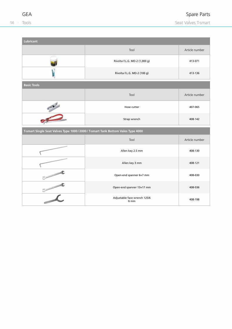
56 ·
GEA
Lubricant
Tool Article number
Rivolta F.L.G. MD-2 (1,000 g) 413-071
Rivolta F.L.G. MD-2 (100 g) 413-136
Basic Tools
Tool Article number
Hose cutter 407-065
Strap wrench 408-142
T-smart Single Seat Valves Type 1000 / 2000 / T-smart Tank Bottom Vales Type 4000
Tool Article number
Allen key 2.5 mm 408-130
Allen key 3 mm 408-121
Open-end spanner 6×7 mm 408-030
Open-end spanner 13×17 mm 408-036
Adjustable face wrench 125/66 mm
408-198
Spare Parts
Tools Seat Valves T-smart

· 57
GEA
6
T-smart Double Seal Valves Type 5000
Tool Article number
Allen key 2.5 mm 408-130
Allen key 3 mm 408-121
Open-end spanner 6×7 mm 408-030
Open-end spanner 13×17 mm 408-036
Open-end spanner 21×23 mm 408-046
Open-end spanner 30×32 mm 408-041
Adjustable face wrench 125/66 mm
408-198
Spare Parts
Tools Seat Valves T-smart
T-smart Double Seat Valves Type 3000
Tool Article number
Ring screw M14
The ring screw can be used for installation and maintenance of a double-seat valve T-smart 3000. For this, the ring screw must be screwed
into the piston stem of the actuator after disassembly of the control top, which permits secure transport with the present lifting equipment.
221-104.98
Allen key 2.5 mm 408-130
Allen key 3 mm 408-121
Open-end spanner 13×17 mm 408-036
Adjustable face wrench 125/66 mm
408-198
Snap ring pliers for shafts A31, 40-100
9065839
Mounting tool DSV 231-000275

58 ·
GEA
T.VIS® control top
The T.VIS® control top is an optimal system for controlling and monitoring GEA Tuchenhagen valves.
This is available in several variants depending on the valve type, tasks and user convenience.
Common features of all T.VIS® variants are:
• Flexible modular system for optimum variant configuration for the particular task (e.g. type of interface module, number of solenoid valves, etc.)
• Internal air supply for high security against failure of the main valve functions because no external air hose is required
• Characteristic design
• High Protection class (min. IP66, optional IP67 or IP69k)
• Ease of cleaning without dead zones, whatever the installation orientation
• Clear visualization of the valve status via a light dome visible 360°, which is illuminated by colored LEDs
• Low energy consumption
• Ease of handling
• Maintenance-free electronic modules
• Many special options, e.g.: • Air throttles • Cable connections, etc.
For maintenance work on the valve, the control tops can be removed from the valve actuator by loosening two bolts on the clamp, without electrical or pneumatic connections having to be disconnected.
T.VIS® concept – for valves with pneumatic actuator
T.VIS® M-15 – control top with manual sensor setting
• For open/close position feedback and actuator control
• Proven sensor technology• Modules and solenoid valves can
be retrofitted
T.VIS® A-15 – control top with automatic set-up
• For open/close position feedback and actuator control
• Automatic set-up• Semi-automatic setup
INA – proximity switch holder on the actuator
• For 2 proximity switches M12×1
Overview
Control and Feedback Systems

· 59
7
GEA
The certificates listed here are valid for corresponding GEA control and feedback systems. Components conforming to the requirements of the European Hygienic Engineering and Design Group (EHEDG) as well as 3-A Sanitary Standards, Inc. (3-A SSI) are available for numerous fields of applications.
EHEDG certificates apply only to the specific control head type as listed. However, they can be transferred to other types, owing to identical design characteristics.
Moreover, independent, standardized tests have confirmed the efficient, problem-free cleanability of numerous components – for optimum safety and economic gain.
Certificates
Certificates
Control and Feedback Systems
Optional Certificates
Ind
ex
ATE
X
GO
ST
Schu
tzar
t
IP67
, IP6
6,
IP69
k
UL
/ CSA
Con
trol
and
Fe
edba
ck S
yste
ms 7 T.VIS® M-15 • •
7 T.VIS® A-15 • • •
7 INA •
7 Connection 0

60 ·
GEA
4 – 20 mA (3-wire)
Function
Available interface
Product
Available for
Control and feedback
DeviceNet
24 V DC
AS-i
Control top (solenoid valves
possible)
Automatic set-up
Manual sensor setting
T.VIS® M-15
T-smart 1000 and 2000
Shut-off and Divert Valves
T-smart 5000Double-seal Valves
T-smart 4000Tank Bottom Valves
T-smart 3000Mixproof Valves
T.VIS® A-15
Selection Matrix of Control and Feedback Systems for Valves with Pneumatic Actuator

Without feedbackControl and feedback
Manual proximityswitch setting
INA Connection 0
Proximity switch (without solenoid
valves)
· 61
7
Control and Feedback Systems

62 ·
GEA
Concept
The T.VIS® M-15 is equipped with manually adjustable sensors and a modular system of options, all of which form the basics of the T.VIS® feedback technology. This means it is optimally adapted to the basic requirements of the process system.
With proven sensor technology, it offers the advantages of the modern T.VIS® series in an inexpensive manner.
Standard variant
Structure
The T.VIS® M-15 is characterized by proven sensor technology. The basic equipment of the control top comprises of the 24 V DC interface module with two sensors for feedback of the valve position and three solenoid valves which can be installed subsequently, if necessary. In the interface types with AC (alternating current), DeviceNet and AS-Interface, an adapter module is connected ahead of the standard interface module, and can also be retrofitted or converted.
A replaceable filter in the supply air connection protects the solenoid valves.
Features
Flexible modular system
Use of proven sensor technology
Quick and easy adjustment of the sensors
Valve status indication by LED
Various communication standards available
Components can be upgraded / converted subsequently
Filter protects solenoid valves
High-quality pneumatic fittings
Exchangeable compressed air connection
Supply and exhaust air throttles can be fitted
Standard protection class IP66
T.VIS® M-15 Overview
Control and Feedback Systems
1
6 7
4
2 3 3
5
1 Pneumatic block
2 24 V DC interface module
3 Sensors
4 Solenoid valves
5 LED lighting
6 Central compressed air connection with replaceable filter
7 Cable gland

· 63
7
GEA
Position detection
Inductive sensor system – The valve positions are detected using two manually adjustable sensors.
Setting
Mechanical – the sensors are calibrated mechanically using the positioning spindles, which are subsequently secured to prevent self-adjustment.
Visualization
LED display: • green • yellow
T.VIS® M-15 Overview
Control and Feedback Systems

64 ·
GEA
Type of interface 24 V DC, 3-wire, PNP24 V DC, 3-wire, NPN
Supply
Operating voltage 24 V DC (+20 %, −12.5 %)
No-load current ≤ 40 mA
Maximum current consumption 255 mA
Polarity reversal protection Yes
Inputs
Activation voltage 21 – 28.8 V = high; < 16 V = low
Current consumption per input ≤ 35 mA
Activation “PV Y1” Direct PV activation
Activation “PV Y2” Direct PV activation
Activation “PV Y3” Direct PV activation
Outputs
Connection type 24 V DC (PNP / NPN with changeover function)
Maximum current carrying capacity per feedback output 50 mA
Voltage drop on the outputs ≤ 3 V
Feedback “start position” Electronic outputs
Feedback “end position” Electronic outputs
Feedback “seat lift position” Electronic outputs
Technical data of the standard version
Position detection Sensors
Housing material PA 12/L
Ambient temperature −20 to +55 °C
Air supply Pressure range 2 to 8 bar
Standard acc. to ISO 8573-1:2010
Solid content Quality class 6
Water content Quality class 4
Oil content Quality class 3
Dimensions of air connections Metric 6/4 mm, inch 6.35/4.31 mm (¼")
Protection class IP66 (powerful water jet)
Sound pressure level via exhaust air throttle Max. 72 dB
Visualization LED (green, yellow)
T.VIS® M-15 – V DC
Control and Feedback Systems

· 65
7
GEA
Position Description of the order code
13 Feedback location
TM15 Control top T.VIS® M-15
14 Control top type
N Without solenoid valve
P 1 solenoid valve Y1
R 1 solenoid valve Y1 (retrofittable: Y2, Y3)
I 2 solenoid valves Y1, Y2 (retrofittable: Y3)
J 2 solenoid valves Y1, Y3 (retrofittable: Y2)
L 3 solenoid valves Y1, Y2, Y3
15 Feedback
2 2 feedbacks
16 Type of interface
B 24 V DC, 3-wire, PNP
N 24 V DC, 3-wire, NPN
17 Solenoid valve
A 24 V DC, 0.85 W
0 Without
18 Screw fitting
M Metric air connection, M20×1.5 cable gland
Z Inch air connection, 0.5" NPT cable gland
J Metric air connection, 5-pin M12 plug (1 solenoid valve, 2 feedbacks)
P Inch air connection, 5-pin M12 plug (1 solenoid valve, 2 feedbacks)
H Metric air connection, 8-pin M12 plug (> 1 solenoid valve, > 2 feedbacks)
I Inch air connection, 8-pin M12 plug (> 1 solenoid valve, > 2 feedbacks)
B Inch air connection, Brad Harrison 0.5" NPT 5-pin plug (US)
Options (multiple selection possible)
/18 Supply air throttle: regulates the opening speed of the valve
/19 Exhaust air throttle: regulates the closing speed of the valve
/225-pin M12 connection socket for screw fitting J, P (article no. 508-963)8-pin M12 connection socket for screw fitting H, I (article no. 508-061)
/67 Protection class IP67 (temporary immersion)
/69k Protection class IP69k (high pressure spray down)
/UC Certification UL / CSA
Position 13 14 15 16 17 18 Options
Code TM15 2
The code is composed as following, depending on the chosen configuration:
T.VIS® M-15 – V DC
Control and Feedback Systems

66 ·
GEA
Type of interface AS-Interface bus DeviceNet
Supply
Operating voltage 25.0 – 31.6 V DC 21 – 26 V DC
No-load current ≤ 62 mA ≤ 58 mA (at 24 V DC)
Maximum current consumption 140 mA 140 mA
Polarity reversal protection Yes Yes
Specification AS-i V3.0 (max. 62 slaves with master V3.0)
Additional information IO.ID.ID2-code: 7.A.E EDS file: F1022_R4.eds
Certificate AS-i association ODVA
Inputs
Feedback “start position” Data bit DI 0 Data bit I-0
Feedback “end position” Data bit DI 1 Data bit I-1
Feedback “seat lift position” (ext. NI) Data bit DI 2 Data bit I-2
Collective fault Data bit I-7
Outputs
Activation “PV Y1” Data bit DO 0 Data bit O-0
Activation “PV Y2” Data bit DO 1 Data bit O-1
Activation “PV Y3” Data bit DO 2 Data bit O-2
Technical data of the standard version
Position detection Sensors
Housing material PA 12/L
Ambient temperature −20 to +55 °C
Air supply Pressure range 2 to 8 bar
Standard acc. to ISO 8573-1:2010
Solid content Quality class 6
Water content Quality class 4
Oil content Quality class 3
Dimensions of air connections Metric 6/4 mm, inch 6.35/4.31 mm (¼")
Protection class IP66 (powerful water jet)
Sound pressure level via exhaust air throttle Max. 72 dB
Visualization LED (green, yellow)
T.VIS® M-15 – AS-i / DeviceNet
Control and Feedback Systems

· 67
7
GEA
Position Description of the order code
13 Feedback location
TM15 Control top T.VIS® M-15
14 Control top type
N Without solenoid valve
P 1 solenoid valve Y1
R 1 solenoid valve Y1 (retrofittable: Y2, Y3)
I 2 solenoid valves Y1, Y2 (retrofittable: Y3)
J 2 solenoid valves Y1, Y3 (retrofittable: Y2)
L 3 solenoid valves Y1, Y2, Y3
15 Feedback
2 2 feedbacks
16 Type of interface
A AS-Interface bus
D DeviceNet
17 Solenoid valve
A 24 V DC, 0.85 W
0 Without
18 Screw fitting
A Metric air connection M20×1.5 cable gland with connection box on cable 1 m (AS-i)
S Inch air connection M20×1.5 cable gland with connection box on cable 1 m (AS-i)
L Metric air connection, 2-pin M12 plug (AS-i)
U Inch air connection, 2-pin M12 plug (AS-i)
D Metric air connection, 5-pin M12 plug (DeviceNet)
K Inch air connection, 5-pin M12 plug (DeviceNet)
Options (multiple selection possible)
/18 Supply air throttle: regulates the opening speed of the valve
/19 Exhaust air throttle: regulates the closing speed of the valve
/22 5-pin M12 connection socket for screw fitting L, U, D, K (A-coded, article no. 508-963)
/67 Protection class IP67 (temporary immersion)
/69k Protection class IP69k (high pressure spray down)
/81 AS-i connection box on cable 1 m with M12 connection socket (article no. 508-027) for screw fitting L, U
/82 AS-i connection box on cable 2 m with M12 connection socket (article no. 508-028) for screw fitting L, U
/UC Certification UL / CSA
The code is composed as following, depending on the chosen configuration:
Position 13 14 15 16 17 18 Options
Code TM15 2
T.VIS® M-15 – AS-i / DeviceNet
Control and Feedback Systems

68 ·
GEA
Concept
The T.VIS® A-15 is equipped with a high-precision path measuring system. This automatic open/close position recognition is available on any valve from GEA Tuchenhagen, along with a T.VIS® feedback system.
Development has focussed on the requirements and necessities of our customers from the fluid-processing industry. In addition to safe control and monitoring of all functions of the process valves in breweries, dairies, plants for manufacturing fruit juices as well as pharmaceuticals, the T.VIS® A-15 offers significant advantages that are directly reflected in lower total cost of ownership.
Standard variant
Structure
The T.VIS® A-15 is equipped with a precise path measuring system for detecting its position.
The necessary wiring for control and feedback is performed, depending on the requirements, via the M12 plug connections accessible from the outside or through direct wiring and cable glands.
The control top can be opened for this.
Operation and configuration of the T.VIS® A-15 takes place either by the two push buttons on the cap or, with the cap removed, via the buttons below. The push buttons are secured electronically against inadvertent or incorrect operation, while in operating mode.
A replaceable filter, in the supply air connection, protects the solenoid valves.
Features
Quick, automatic initialization
Tamper-proof setting of tolerances
Reduced energy consumption
Reduction in operating costs
Valve status display by LED
Basic LED colors can be selected specifically for the customer
Filter protects solenoid valves
High-quality pneumatic fittings
Exchangeable compressed air connection
Supply and exhaust air throttles can be fitted
Semi-automatic setup
Standard protection class IP66
T.VIS® A-15 Overview
Control and Feedback Systems
9
5
1
6
3
4
2
8
7
1 Pneumatic block
2 Control unit
3 Path measuring system
4 Solenoid valves
5 LED lighting
6 2 push buttons
7 Central compressed air connection with replaceable filter
8 M12 plug connection
9 Logic NOT-element

· 69
7
GEA
Position detection
Path measuring system – the valve position is registered by means of a highly modern path measuring system.
Setting
Automatic – following unlocking, simply pressing the two buttons on the cap of the T.VIS® A-15 starts the initialization process which runs fully automatically. There is no need to open the control top for this purpose, resulting in particularly quick, easy and safe commissioning of the control top (on average < 1 minute).
Immediately following the set-up, it is possible to set the open/close position tolerances and signal attenuation in the parameter menu.
Semi-automatic setup
As a new feature, our control top T.VIS® A-15 has the option of semi-automatic setup that permits uncomplicated exchange in the current process.
For more information about the semi-automatic setup, refer to the end of this section.
Visualization
LED display: • Green • Yellow • Red
The programmable color change allows the display of colors yellow and green to be swapped over.
Protection class IP66
T.VIS® A-15 Overview
Control and Feedback Systems

70 ·
GEA
Technical data of the standard version
Position detection Path measuring system
Housing material PA 12/L
Ambient temperature −20 to +55 °C
Air supply Pressure range 2 to 8 bar
Standard acc. to ISO 8573-1:2010
Solid content Quality class 6*
Water content Quality class 4
Oil content Quality class 3
Dimensions of air connections Metric 6/4 mm, inch 6.35/4.31 mm (¼")
Protection class IP66 (powerful water jet)
Sound pressure level via exhaust air throttle Max. 72 dB
Visualization LED (green, yellow, red)
* Recommended
T.VIS® A-15 – 24 V DC / AS-i /DeviceNet
Control and Feedback Systems
Type of interface 24 V DC, 3-wire, PNP AS-Interface bus DeviceNet
Supply
Operating voltage 24 V DC (+20 %, −12.5 %) 26.5 – 31.0 V DC 21.5 – 26.0 V DC
No-load current ≤ 25 mA ≤ 25 mA ≤ 35 mA
Maximum current consumption 205 mA 105 mA 90 mA
Polarity reversal protection Yes Yes Yes
Specification AS-i V3.0 (max. 62 slaves)
Additional information IO.ID.ID2-code: 7.A.E. 221-002917DNET-TVIS_R1.eds
Conformity AS-i association ODVA
Inputs
Connection type 24 V DC (PNP)
Short circuit-proof Yes
Overload-proof Yes
Maximum current carrying capacity per feedback output
100 mA
Voltage drop on the outputs ≤ 1 V
Feedback “start position” Electronic output Data bit DI 0 Data bit I-0
Feedback “end position” Electronic output Data bit DI 1 Data bit I-1
Feedback “seat lift position” Electronic output Data bit DI 2 Data bit I-2
Outputs
Activation voltage > 13 V = high; < 6 V = low
Current consumption per input < 10 mA
Activation “PV Y1” Electronic input Data bit DO 0 Data bit O-0
Activation “PV Y2” Electronic input Data bit DO 1 Data bit O-1
Activation “PV Y3” Electronic input Data bit DO 2 Data bit O-2

· 71
7
GEA
Position Description of the order code
13 Feedback location
TA15 Control top T.VIS® A-15
14 Control top type
N Without solenoid valve
P 1 solenoid valve Y1
I 2 solenoid valves Y1, Y2 (Y2 for lower seat lift)
J 2 solenoid valves Y1, Y3 (Y3 for upper seat lift, air/air actuator or external process valve)
L 3 solenoid valves Y1, Y2, Y3
15 Feedback
8 2 digital feedbacks
16 Type of interface
A AS-Interface BUS
B 24 V DC PNP
D DeviceNet
17 Solenoid valve
A 24 V DC, 0.85 W
0 Without
18 Screw fitting
J Metric air connection, 5-pin M12 plug for 24 V DC (1 PV, 2 feedbacks), AS-i
P Inch air connection, 5-pin M12 plug for 24 V DC (1 PV, 2 feedbacks), AS-i
H Metric air connection, 8-pin M12 plug for 24 V DC (> 1 solenoid valve, > 2 feedbacks)
I Inch air connection, 8-pin M12 plug for 24 V DC (> 1 solenoid valve, > 2 feedbacks)
M Metric air connection, M20×1,5 cable gland with integrated terminal strip for 24 V DC
Z Inch air connection, 0.5" NPT cable gland with integrated terminal strip for 24 V DC
Options (multiple selection possible)
/18 Supply air throttle: regulates the opening speed of the valve
/19 Exhaust air throttle: regulates the closing speed of the valve
/2224 V DC / AS-i : 5-pin connection socket for screw fitting J, P (article no. 508-963)24 V DC: 8-pin connection socket for screw fitting H, I (article no. 508-061)
/67 Protection class IP67 (temporary immersion)
/69k Protection class IP69k (high pressure spray down)
/81 AS-i connection box on cable 1 m with 5-pin M12 connection socket (article no. 508-027)
/82 AS-i connection box on cable 2 m with 5-pin M12 connection socket (article no. 508-028)
/UC Certification UL / CSA
The code is composed as following, depending on the chosen configuration:
Position 13 14 15 16 17 18 Options
Code TA15 8
T.VIS® A-15 – 24 V DC / AS-i/DeviceNet
Control and Feedback Systems

72 ·
GEA
Technical data
Material 1.4301 (AISI 304)
Surface Metal blank
Technical data
Material 1.4301 (AISI 304)
Surface Metal blank
Connection 0
Connection 0 can be used as an alternative to feedback systems if no feedback sensors are wanted above the actuator. Connection 0 is available in a metric and inch variant.
INA – proximity switch holder on the actuator
The proximity switch holder M12×1 (INA) makes it possible to use feedback sensors above the actuator. The proximity switch holder has prepared M12×1 holes which allow the sensors to be set optimally. A direct connection to the controller provides the feedback on the valve position.
Connection 0, INA, LAT
Control and Feedback Systems

· 73
7
GEA
Position Description of the order code
13 Feedback location
000 Connection 0 (without feedback)
INA. Proximity switch holder for connection 0 for max. 2 proximity switches M12×1
14 Control top type
0 Connection 0
15 Feedback
0 Without (INA, 000)
1 1 feedback (INA, LAT)
2 2 feedbacks (INA, LAT)
16 Type of switch
0 Without (INA, 000)
B NI 24 V DC 3-wire PNP M12×1 with terminal chamber (INA)
F NI 24 V DC 2-wire M12×1 with terminal chamber (INA)
E NI NAMUR M12×1 with terminal chamber (INA)
X NI 24 V DC 3-wire NPN M12×1 with terminal chamber (INA)
S NI 24 V DC 3-wire PNP M12×1 with plug connector (INA)
17 Cable connection
0 Without
18 Air connection
0 Without
M Metric (article no. 221-140.02)
Z Inch (article no. 2214-140.04)
The code is composed as following, depending on the chosen configuration:
Position 13 14 15 16 17 18 Options
Code 0 0
Connection 0, INA, LAT
Control and Feedback Systems

74 ·
GEA Control and Feedback Systems
External proximity switches M12×1 for mounting on the actuator or in the lantern.
Proximity Switches
Technical data
Protection class IP67
Operating voltage 10 – 30 V DC
Material PA 12 / VA
Permitted ambient temperature −25 to +85 °C
Technical data
Protection class IP67
Operating voltage 8.2 V DC nom.
Material Brass, chrome-plated / PA12
Permitted ambient temperature −25 to +70 °C
Marking II 2 G EEx ia IIC T6
Technical data
Protection class IP67
Operating voltage 7.5 – 30 V DC
Material 316L / PEEK
Permitted ambient temperature −20 to +55 °C
Proximity switch M12×1 for INA, LAT
Nominal switching distance
Article no.
2-wire(terminal chamber) 2 mm 505-104
3-wire PNP(terminal chamber) 3 mm 505-088
3-wire PNP(Connector M12×1) 4 mm 505-096
4-wire NPN / changeover contact (terminal chamber)
3 mm 505-105
Electrical connection by M12×1 connector
Electrical connection by wiring in the terminal chamber
Proximity switch M12×1 for T.VIS®
Nominal switching distance
Article no.
2-wire/ NAMUR(Connector M12×1) 4 mm 505-098
2-wire / NAMUR(Connector M12×1) 2 mm 505-102
Proximity switch M12×1 for SES
Nominal switching distance
Article no.
2-wire / NAMUR(terminal chamber) 2 mm 505-085

· 75
7
GEA
Switch bars
The following components are required for subsequent installation of a control and feedback system on a T-smart valve.
T-smart seat valves
T.VIS® M-15 T.VIS® A-15
Switch bar T.VIS® 221-589.80 221-589.75
Switch bar 221-589.75 for T.VIS® A-15
Switch bar 221-589.80 for T.VIS® M-15
Basic switch bar for T.VIS
Basic switch bar for the use with T.VIS®
Adaptation
Control and Feedback Systems
Additionally, the basic switch bar needs to be exchanged for type 1000, 2000, 4000 + 5000 when upgrading to the use of a T.VIS(R). For the T-smart Mixproof Valve (Type 3000) the basic switch bar is fixed in the actuator. Therefore, no exchange is necessary.
In the following table the basic switch bars can be found according to nominal size and valve type.
T-smart Single Seat Valves Type 1000 / 2000, T-smart Double Seal Valves Type 5000
Nominal width Switch barDN OD Article number
25, 40, 50 1", 1 ½", 2" 231-00001065 2 ½", 3" 231-000011
80, 100 4" 231-000012
T-smart Tank Bottom Valves Type 4000
Nominal width Switch barDN OD Article number25, 1", 231-000010
40, 50 1 ½", 2" 231-00001165, 80, 100 2 ½", 3", 4" 231-000012

76 ·
GEA
The IP protection classes inform about the scope at which the housing of an electrical device is protected against ingress of solids (first number) and moisture (second number).
So called IP-codes are assigned to the protected systems. Their index figures represent common error options against which the system is protected. The code starts with the letters IP for “International Protection”.
Meaning of the index numbers
If an index number is not to be stated, it is replaced by the letter x (e.g. IPx6).
For the 2nd index figure (protection from moisture), the following applies: • The protection class IPx6 includes all protection classes below. • This does not apply to the higher protection class IPx7.
If this protection class is to include a lower protection class, this is to be indicated by a combination of index figures (e.g. IP67/69k).
The T.VIS® control top designs of the M-15 and A-15 comply with the requirements of protection class IP66 (DIN EN 60529) as standard. Designs in the stronger protection classes IP67 or IP69k (both DIN EN 60529) are also available.
1. Index* Protection from solids
6 Dust-tight
2. Index* Protection from moisture
6 Protection from powerful water jet
7 Protection from temporary immersion
9kProtection from water at high pressure/ steam jet cleaning
* Further indices and more precise explanations can be found in the corresponding standard.
IP protection classes
Control and Feedback Systems

· 77
7
GEA Control and Feedback Systems
By means of the semi-automatic setup, a control top can be replaced without interrupting the current process.
For this, an employee only needs to perform the simple configuration once on site: in the version in protection class IP66 with two push buttons on the T.VIS® cap, and for the optional protection classes IP67 and IP69k with the cap removed right with the two buttons below.
For the semi-automatic set-up, the control top initially only learns the position of the valve disc on the non-actuated position and then remains until the valve is actuated in the scope of a running process. Only then will the end position of the valve be stored. The process thus does not need to be stopped!
The semi-automatic set-up is integrated into the T.VIS® A-15 as standard and does not require any additional hardware.
Semi-automatic Setup

78 ·
GEA
Order code for air connection
In conjunction with screw fitting or plug Use Matching connection socket
Metric Inch Option Article no. Designation
MM20×1.5 cable gland
T.VIS® M-15T.VIS® A-15
– – –
Z0.5" NPT cable gland
T.VIS® M-15T.VIS® A-15
– – –
A S
M20×1.5 cable gland with connection box on cable 1 m
T.VIS® M-15 (AS-i) – – –
L U2-pin M12-plug (A-coded)
T.VIS® M-15 (AS-i)
/22 508-9635-pin M12 connection socket(A-coded)
/81 508-027
AS-i connection box on cable 1 m with 5-pin M12 connection socket (A-coded)
/82 508-028
AS-i connection box on cable 2 m with 5-pin M12 connection socket (A-coded)
D K5-pin M12 plug (A-coded)
T.VIS® M-15 (DeviceNet) /22 508-9635-pin M12 connection socket (A-coded)
J P5-pin M12-plug (A-coded)
T.VIS® M-15 (24 V DC)
/22 508-9635-pin M12 connection socket (A-coded)T.VIS® A-15 (24 V DC)
T.VIS® A-15 (AS-i)T.VIS® A-15 (DeviceNet)
H I8-pin M12-plug (A-coded)
T.VIS® M-15 (24 V DC)
/22 508-0618-pin M12 connection socket (A-coded)
T.VIS® A-15 (24 V DC)
BBrad Harrison 0.5" NPT 5-pin plug
T.VIS® M-15 (24 V DC) – – –
Connection Screw Fitting
Control and Feedback Systems

· 79
7
GEA Control and Feedback Systems
24 V (PNP / NPN)
In 24 V parallel wiring digital signals are exchanged between a terminal unit and generally the corresponding input and output modules of a PLC. In this case, it is necessary to have a separate wire for each signal, usually in the form of a multi-core cable.
PNP (current-supplying) indicates signal transfer against reference potential L−.
NPN (current-drawing) indicates signal transfer against reference potential L+.
BUS AS-Interface
AS-Interface (Actuator-Sensor Interface) is a standard in fieldbus communication that was developed for connecting actuators and sensors. This is to replace parallel wiring used in the past. The AS-Interface has been an international standard acc. to EN 50295 and IEC 62026-2 since 1999. AS-i products are certified by the AS International Association, thereby, ensuring that equipment from different manufacturers will work together in the same system. The transmission medium is an unshielded, two-core yellow cable which also carries the electrical power supply (24 – 30 V direct current voltage) for the communication electronics and the slaves. A maximum of 62 slaves can be used per AS-i master. The slaves are addressed manually using a manual addressing unit or automatically by the master. The maximum length of the AS-i cable is 100 m, although by using repeaters it is possible to extend the entire length up to 400 m.
DeviceNet bus
DeviceNet is a CAN-based fieldbus that is chiefly used in automation engineering. DeviceNet was developed by Allen-Bradley (part of Rockwell Automation) and later transferred to the ODVA (Open DeviceNet Vendor Association) as an open standard. DeviceNet is chiefly used in the USA and, to a certain extent, Asia. A maximum of 64 network nodes can be used per fieldbus segment. The nodes address is set either using dial or DIP switches on the device, or can be configured using the bus on the basis of software. The maximum length of the DeviceNet cable depends on the selected cable type and baud rate, although it cannot exceed 500 m.
4 – 20 mA (3-wire)
In industrial automation engineering, the 4 – 20 mA current signal is the one most frequently used for analog measured value transmission. The enormously widespread use of this type of signal is explained by its ease of handling and, above all, its resistance to interference.
Using 4 mA as the initial value instead of 0 mA makes it very easy to detect and evaluate a wire break. As a rule, 4 – 20 mA corresponds to 0 – 100 % of the physical measuring range of an analog sensor or the working range of an actuator set in the parameters; the nominal value is supplied or the actual value is returned via an interface of this kind.
Interface Types


· 81
GEA
Position Description of the order code
13 Feedback location
TM15 Control top T.VIS® M-15
14 Control top type
N Without solenoid valve
P 1 solenoid valve Y1
R 1 solenoid valve Y1 (retrofittable: Y2, Y3)
I 2 solenoid valves Y1, Y2 (retrofittable: Y3)
J 2 solenoid valves Y1, Y3 (retrofittable: Y2)
L 3 solenoid valves Y1, Y2, Y3
15 Feedback
2 2 feedbacks
16 …
Position Description of the order code for the standard version
1 Valve type
3 Mixproof Shut-off Valves
2 Housing combinations
022
E
3 Nominal width standard
0 OD 1 DN
4 Nominal width
100 OD 1" 025 DN 25
150 OD 1 ½" 040 DN 40
200 OD 2" 050 DN 50
250 OD 2 ½" 065 DN 65
300 OD 3" 080 DN 80
400 OD 4" 100 DN 100
5 Non-actuated position
0 Closed
6 Air connection
0 Without
1 Metric
2 Inch
7 …
Example for a complete order code, comprising valve and feedback system:
Procedure for valve selection
Procedure for feedback system selection
Position 13 14 15 16 17 18 Options
Code TM15 P 2 B A M
Position 1 2 3 4 5 6 7 8 9 10 11 12
Code 3 022 - 0 200 - 0 1 1 0 - 0 0 0 0 +
Sample Composition of the Order Code
Appendix

82 ·
GEA
Available for T-smart
1000 2000 3000 5000 4000
•
•
•
•
•
• •
• •
•
•
•
•
•
•
•
•
Position Description of the order code
1 Valve type
1 Shut-off valve
2 Divert valve
3 Double-seat valve
5 Double-seal valve
4 Tank bottom valve
2 Housing combinations
007
L L
003
T T
017
K
027
P
022
E
011
B
012
C
021
A
001
F
002
D
The complete order code shows all the possible configurations for seat valves of the series T-smart at a glance. All available variants for the particular series are contained.
Complete Order Code

· 83
* Only for divert valve type 2017 ** Only for double-seat valve type 3011
Position Description of the order code
3 Nominal width standard
0 OD 1 DN
4 Nominal width
100 OD 1" 025 DN 25
150 OD 1 ½" 040 DN 40
200 OD 2" 050 DN 50
250 OD 2 ½" 065 DN 65
300 OD 3" 080 DN 80
400 OD 4" 100 DN 100
5 Non-actuated position
0 Closed
1 Opened
6 Air connection
0 Without
1 Metric
2 Inch
7 Port orientation top
0 0°
1 90°
2 180°
3 270°
8 Flushing valves
0 Plastic (for temperatures up to 80 °C)
1 Stainless steel (for temperatures above 80 °C)
9 Seal material
0 EPDM
10 Port orientation bottom
0 No connection
11 Connection fittings
0 Welding end
1 Tri-clamp
12 Certificates
0 Without
1 Test report 2.2
2 Inspection certificate 3.1
3 Certificates 2.2 and 3.1
Available for T-smart
1000 2000 3000 5000 4000
• • • • •
• • • • •
• • • • •
• • • • •
• • • • •
• • • • •
• • • • •
• • • • •
• •
• • • • •
• • • • •
• • • • •
• • • •
• •
•* •**
•* •**
• • • • •
•
• • • • •
• • • • •
• • • • •
• • • • •
• • • • •
• • • • •
• • • • •
• • • • •
Position 1 2 3 4 5 6 7 8 9 10 11 12Code for control and feedback systems, see section 7
Code - - - 0 0 +
Appendix
Seat Valves T-smart

84 ·
GEA
The complete order code makes it possible to assemble an order code for a control and feedback system. All options possible for the particular control or feedback system are included.
Position Description of the order code
13 Feedback location
TM15 Control top T.VIS® M-15
TA15 Control top T.VIS® A-15
000 Connection 0
INA. Proximity switch mount for connection 0 for 2× proximity switches M12×1
14 Control top type
0 Connection 0
N Without solenoid valve
P 1 solenoid valve Y1
R 1 solenoid valve Y1 (for T.VIS® M-15 retrofittable: Y2, Y3)
I 2 solenoid valves Y1, Y2 (for T.VIS® M-15 retrofittable: Y3)
J 2 solenoid valves Y1, Y3 (for T.VIS® M-15 retrofittable: Y2)
L 3 solenoid valves Y1, Y2, Y3
15 Feedback
0 Without feedback
1 1 feedback
2 2 feedbacks
8 2 digital feedbacks
16 Type of interface/type of switch
0 Without
A AS-interface bus
B 24 V DC, 3-wire, PNP
B NI 24 V DC 3-wire PNP M12×1 with terminal chamber
D DeviceNet
E NI NAMUR M12×1 with terminal chamber
F NI 24 V DC 2-wire M12×1 with terminal chamber
N 24 V DC, 3-wire, NPN
S NI 24 V DC 3-wire PNP M12×1 with plug connector
X NI 24 V DC 3-wire NPN M12×1 with terminal chamber
17 Solenoid valve
0 Without
A 24 V DC, 0,85 W
Available for control and feedback system
TM15 TA15 000 INA
•
•
•
•
•
• •
• •
•
• •
• •
• •
• •
•
• •
•
• •
• •
• •
•
•
•
•
•
•
•
• • • •
• •
Complete Order Code

· 85
Position Description of the order code
18 Connection screw fitting/air connection
0 Without
A Metr. air connection M20×1.5 cable gland with connection box on cable 1 m (AS-i)
B Inch air connection, Brad Harrison 0.5" NPT 5-pin plug (US)
D Metr. air connection, 5-pin M12 plug (DeviceNet)
H Metr. air connection, 8-pin M12 plug (> 1 solenoid valve, > 2 feedbacks)
I Inch air connection, 8-pin M12 plug (> 1 solenoid valve, > 2 feedbacks)
J Metr. air connection, 5-pin M12 plug (1 solenoid valve, 2 feedbacks)
K Inch air connection, 5-pin M12 plug
L Metr. air connection, 2-pin M12 plug (AS-i)
M Metr. air connection, M20×1.5 cable gland
P Inch air connection, 5-pin M12 plug (1 solenoid valve, 2 feedbacks)
S Inch air connection M20×1.5 cable gland with connection box on cable 1 m (AS-i)
U Inch air connection, 2-pin M12 plug (AS-i)
Z Inch air connection, 0.5" NPT cable gland
Options
/18 Supply air throttle: regulates the opening speed of the valve
/19 Exhaust air throttle: regulates the closing speed of the valve
/22 5-pin M12 connection socket for screw fitting (A-coded)
/66 Protection class IP66 (temporary immersion)
/67 Protection class IP67 (temporary immersion)
/69k Protection class IP69k (high-pressure spray down)
/81AS-i connection box on cable 1 m with M12 connection socket for screw fitting L, U
/82AS-i connection box on cable 2 m with M12 connection socket for screw fitting L, U
/UC Certification UL/CSA
Available for control and feedback system
TM15 TA15 000 INA
• •
•
•
•
• •
• •
• •
•
•
• • • •
• •
•
•
• • • •
• •
• •
• •
• •
• •
• •
•
•
• •
Position 13 14 15 16 17 18 Options
Code
Control and Feedback Systems
Appendix

86 ·
GEA
AS-i Actuator Sensor interface. BUS system for the lowest field level.
cCSAus Test of a product by CSA according to applicable safety standards in Canada and the USA.
CE Conformité Européenne. By affixing the CE mark, the manufacturer confirms that the product complies with the European directives applicable to the specific product.
CSACanadian Standards Association. A non-governmental Canadian organization which issues standards as well as checking and certifying the safety of products. It is now globally active.
cULus Test of a product by UL according to applicable safety standards in Canada and the USA.
DeviceNet BUS system of the ODVA organization for complex communication on various field levels.
EG 1935/2004Materials in contact with the product used in valves from GEA Tuchenhagen GmbH are in accordance with EC regulation 1935/2004. This defines a general framework for materials and objects intended to come into contact with foodstuffs.
EHEDGEuropean Hygienic Engineering & Design Group. European supervisory authority for foodstuffs and pharmaceuticals. This authority issues approvals and certificates for products and materials that are used in the foodstuffs and pharmaceuticals industries.
FDAFood and Drug Administration. US supervisory authority for foodstuffs and pharmaceuticals. This authority issues approvals and certificates for products and materials that are used in the foodstuffs and pharmaceuticals industries.
ODVAODVA is a worldwide association comprising leading automation companies. It develops network protocols and standards in the joint interests of its members, which are used for the international interoperability of production systems.
TÜV Technischer Überwachungs-Verein. The German TÜV is a private company which carries out technical safety checks as prescribed in national legislation or regulations.
UL Underwriters Laboratories. An organization founded in the USA for checking and certifying products and their safety.
Description of Certificates
Appendix

· 87
GEA
Abbreviations and Terms
Appendix
Abbreviation Explanation
°C Degrees Celsius, unit of measurement for temperature
°F Degrees Fahrenheit, unit of measurement for temperature
3-A Standard of 3-A Sanitary Standards, Incorporated
3D Three-dimensional
AAmpere, unit of measurement of current intensity or Output, term used in automation
AC Alternating Current
ADI free All elastomer compounds are free of animal-derived ingredients
AISI American Iron and Steel Institute, association of the American steel industry
ANSI American National Standards Institute, American body for standardizing industrial processes
approx. approximately
AS-i Actuator Sensor interface, standard for fieldbus communication
ASME American Society of Mechanical Engineers, professional association of mechanical engineers in the USA
ASME-BPE Standard of the ASME's – bioprocessing equipment association
ATEX Atmosphères Explosibles, synonymous with the directives of the European Union for potentially explosive areas
bar Unit of measurement for pressure. All pressure values [bar/psi] refer to positive pressure [barg / psig], unless specifically stated otherwise.
barg Unit of measurement for pressure relative to atmospheric pressure
CAN Controller Area Network; asynchronous serial bus system
CE Conformité Européenne, administrative symbol for the free movement of industrial products
CIP Cleaning In Place, designates a process for cleaning technical process systems.
CRNCanadian Registration Number,is issued by a Canadian Jurisdiction and covers pressure vessels, fittings, or pressure piping. It is a necessary authorization allowing these components to be in operation in Canada.
CSA Canadian Standards Association, a non-governmental Canadian Standardization organization
Cv The Cv value corresponds to the water flow rate through a valve (in US gal / min) at a pressure differential of 1 PSI and a water temperature of 5 °C to 30 °C. kv = 14,28 Cv (USA).
Cvs The Cv values of a valve at nominal stroke (100 % opening) is designated the Cvs value.
dB Decibel, one tenth of a bel, named after Alexander Graham Bell and used for identifying levels and dimensions
DC Direct Current
DIN Deutsches Institut für Normung e. V. Standardization organization in the Federal Republic of Germany, DIN = synonym for standards issued by the organization

88 ·
GEA
Abbreviations and Terms
Appendix
Abbreviation Explanation
DIP Dual Inline Package, design of a switch
DN Diameter Nominal, DIN nominal width
Device Net Network system used in the automation industry to interconnect control devices for data exchange
E Input, term used in automation
EAC Certification of technical confirmity from the customs union of Russia/Balarus/Kazakhstan
Pressure Equipment Directive 97/23/EC
Directive of the European Parliament and the Council Directive for layout and conformity evaluation for pressure equipment and assemblies with a maximim pressure (PS) of more than 0.5 bars.
EG No. 1935/2004 Regulation of the European Parliament which lays down common rules for materials which come, or may come, into contact with food, either directly or indirectly.
EHEDG European Hygienic Engineering and Design Group. Consortium of equipment manufacturers, food industries, research institutes as well as public health authorities
EN European standard, rules of the European Committee for Standardization
EPDM Ethylene propylene diene rubber, acronym acc. to DIN / ISO 1629
Ex Synonym for ATEX
FDA Food and Drug Administration, official foodstuffs monitoring in the United States
FEM calculation Finite Element Method; calculation process for simulating solids
FKM Fluorinated rubber, acronym acc. to DIN / ISO 1629
GOSTGosudarstvennyy Standart, Certification of conformity for components according to standards and regulations of the Russian Federation
H Henry, unit of measurement for inductance
HNBR Hydrated acrylonitrile butadiene rubber, acronym acc. to DIN / ISO 1629
Hz Hertz, unit of frequency named after Heinrich Hertz
I Formula symbol for electrical current
IEC International Electrotechnical Commission, international standardization organization for electrical and electronic engineering
IP Ingress Protection / International Protection, index of protection class acc. to IEC 60529
IPS Iron Pipe Size, American pipe dimension
ISA International Society of Automation, international US organization of the automation industry
ISOInternational Organization for Standardization, international organization that produced international standards, ISO = synonym for standards from the organization
kg Kilogram, unit of measurement for weight
Kv The Kv value corresponds to the water flow rate through a valve (in m³ / h) at a pressure differential of 0.98 bar and a water temperature of 5 °C to 30 °C.

· 89
GEA
Abbreviations and Terms
Appendix
Abbreviation Explanation
Kvs The Kv values of a valve at nominal stroke (100 % opening) is designated the Kvs value
L Conductive
LED Light-Emitting Diode
LEFF® Function of the T.VIS® valve informations system for cyclical pulsing during the lifting process; Low-Emission Flip Flop
mm Millimeter, unit of measurement for length
MMetric, system of units based on the meter or Mega, one million times a unit
m3/h Cubic meters per hour, unit of measurement for volumetric flow
max. Maximum
NAMUR Standardization working association for measuring and control technology in the chemical industry, synonym for the interface type of the organization, especially for potentially explosive atmospheres
NC Normally Closed; valve or solenoid valve control which is closed in idle status
NO Normally Open; valve or solenoid valve control which is open in idle status
NOT-element Logic element, NOT gate
NPN Signal transmission against reference potential, current-consuming
NPT National Pipe Thread, US thread standard for self-sealing pipe fittings
OD Outside Diameter, pipe dimension
ODVA Open DeviceNet Vendor Association, global association for network standards
PA 12/L Polyamide
Pg Armoured thread
PLC Programmable Logic Controller, device for controlling a machine or system on a digital basis
PMO Pasteurized Milk Ordinance
PN Nominal pressure for pipeline systems according to EN 1333,rated pressure in bar at room temperature (20 °C)
PNP Signal transmission against reference potential, current-supplying
PPO Polyphenylene oxide, thermoplastic material
PS Maximum permitted operating pressure at which the components can operate safely at maximum allowable temperature (TS)
psi Unit of measurement for pressure, pound-force per square inch, 1 psi = 6894.75 Pa. All pressure values [bar/psi] refer to positive pressure [barg / psig], unless specifically stated otherwise.
psig Unit of measurement for pressure relative to atmospheric pressure

90 ·
GEA Appendix
Abbreviations and Terms
Abbreviation Explanation
PV Solenoid valve
Ra in μm Average roughness value, describes the roughness of a technical surface
RM Feedback
International Protection-Code IP67, IP66, IP69K
Classifies and rates the degree of protection provided against intrusion dust, accidental contact, and water
SES GEA Tuchenhagen control head for Ex areas, control top system of GEA Tuchenhagen
SET-UP Self-learning installation, the SET-UP procedure carries out all necessary settings for generating messages during commissioning and maintenance.
SIP Sterilization in Place,refers to a process for cleaning technical process systems
SMS Svensk Mjölk Standard, Scandinavian pipe dimension
SW Indicates the size of a tool spanner, “Schlüsselweite”
TA-LuftVDI 2440
If a product is certified according to TA Luft it meets the requirements for proof of high grade performance according to TA Luft of 1.0x 10⁻⁴ mbar x l / (s x m) at service conditions under the VDI guideline 2440. The product will hence be tested for tightness.
T.VIS® GEA Tuchenhagen valve information system, control top system from GEA Tuchenhagen
TS Maximum permitted operating temperature
T-smart Valve series from GEA Tuchenhagen
UL Underwriters Laboratories, a certification organization established in the USA
USP Class VIThe United States Pharmacopeial Convention (USP) is a scientific nonprofit organization that sets standards to help protecting public health. Class VI administer tests and impacts of material and their substances on animal and human tissues.
UV Ultraviolet, ultraviolet radiation is a wavelength of light
V Volt, unit of measurement for voltage
VARICOMP® Pipe expansion compensator from GEA Tuchenhagen
VMQ High-polymer vinyl methyl polysiloxane, silicone rubber, MVQ = synonym
W Watt, unit of measurement for power
Y Control air connection for the working cylinder, designation from pneumatic systems
μ Micro, one millionth of a unit
Ω Ohm, the unit of electrical resistance named after Georg Simon Ohm

· 91
GEA
Typical application and description
You can receive two-dimensional and/or three-dimensional drawing files of our components for making your piping planning. For this purpose, please send us your specific request, stating the particular order code and the required drawing format. The required files will then be individually prepared for you.
Available drawing formats:
Format Name
2D formats
drw Native Pro / E
igs (2D) IGS file
dxf AutoCAD drawing exchange
pdf (2D) Adobe Acrobat document
tif TIFF (plot)
3D formats
asm Native Pro / E
igs (3D) IGS file
pdf (3D) Adobe Acrobat document
stp STP file
bmp (3D) Bitmap image
jpg (3D) JPEG image
tif (3D) TIFF image
sat Standard ACIS
CAD Files
Appendix

92 ·
GEA
General Sales Terms and Condition of Delivery
Please note
All our sales and/or services are exclusively subject to our valid terms and conditions of sale and/or service applicable in the respective country of business, which can be found on our internet platform: www.gea.com.
If not available or if you otherwise wish to receive such terms and conditions directly from us, please contact us and we of course will send you the applicable version of our terms and conditions for the envisaged business.
Appendix


Seat
Val
ves
T-sm
art
08
/18
©
GEA
Tuc
henh
agen
Gm
bH. A
ll rig
hts
rese
rved
. Tra
dem
arks
with
the
® s
ymbo
l are
reg
iste
red
in c
erta
in c
ount
ries.
S
ubje
ct t
o m
odifi
catio
ns. P
rinte
d in
Ger
man
y.
GEA Germany
GEA Tuchenhagen GmbH
Am Industriepark 2–10
21514 Büchen, Germany
Tel +49 4155 49-0
Fax +49 4155 2035
gea.com
GEA is a global technology company with multi-billion euro sales operations in more than 50 countries. Founded in
1881 the company is one of the largest providers of innovative equipment and process technology. GEA is listed in the
STOXX® Europe 600 Index. In addition, the company is included in selected MSCI Global Sustainability Indexes.
We live our values.Excellence • Passion • Integrity • Responsibility • GEA-versity