CERAMIC PLUG AND SEAT VALVES - PrepquipPrepQuip Ceramic Plug & Seat Valve Information) 2 of 3 mm....
4
(PrepQuip Ceramic Plug & Seat Valve Information) 1 CERAMIC PLUG AND SEAT VALVES 1. Introduction Ceramic Plug and Seat Valves, available from PrepQuip, were initially developed to replace conventional pinch-type valves on column tails discharge systems, in order to reduce excessive downtime and maintenance costs incurred through the frequent replacement of worn pinch valve sleeves. Figure 1: Ceramic plug and seat valves The Ceramic Plug and Seat Valves, which can be automated with an actuator to suit customer applications, are used to control abrasive slurries with a maximum particle size
-
Upload
vuongtuyen -
Category
Documents
-
view
212 -
download
0
Transcript of CERAMIC PLUG AND SEAT VALVES - PrepquipPrepQuip Ceramic Plug & Seat Valve Information) 2 of 3 mm....

(PrepQuip Ceramic Plug & Seat Valve Information) 1
CERAMIC PLUG AND SEAT VALVES
1. Introduction
Ceramic Plug and Seat Valves, available from PrepQuip, were initially developed to
replace conventional pinch-type valves on column tails discharge systems, in order to
reduce excessive downtime and maintenance costs incurred through the frequent
replacement of worn pinch valve sleeves.
Figure 1: Ceramic plug and seat valves
The Ceramic Plug and Seat Valves, which can be automated with an actuator to suit
customer applications, are used to control abrasive slurries with a maximum particle size
(PrepQuip Ceramic Plug & Seat Valve Information) 2
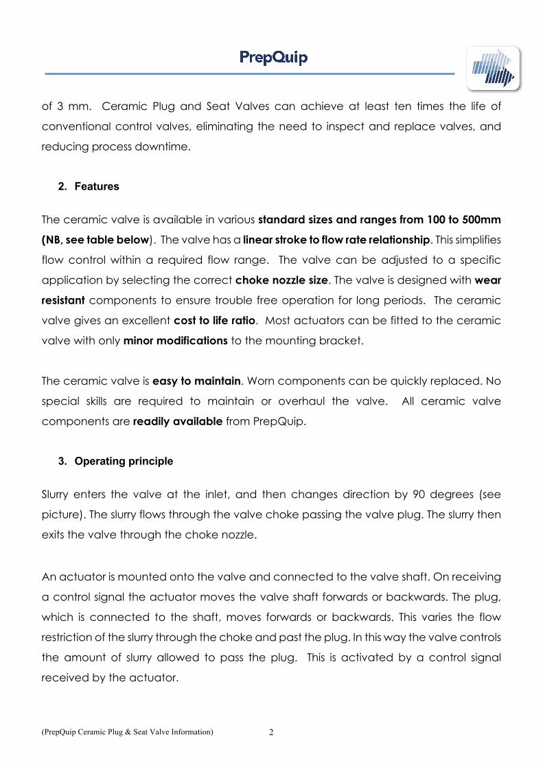
of 3 mm. Ceramic Plug and Seat Valves can achieve at least ten times the life of
conventional control valves, eliminating the need to inspect and replace valves, and
reducing process downtime.
2. Features
The ceramic valve is available in various standard sizes and ranges from 100 to 500mm
(NB, see table below). The valve has a linear stroke to flow rate relationship. This simplifies
flow control within a required flow range. The valve can be adjusted to a specific
application by selecting the correct choke nozzle size. The valve is designed with wear
resistant components to ensure trouble free operation for long periods. The ceramic
valve gives an excellent cost to life ratio. Most actuators can be fitted to the ceramic
valve with only minor modifications to the mounting bracket.
The ceramic valve is easy to maintain. Worn components can be quickly replaced. No
special skills are required to maintain or overhaul the valve. All ceramic valve
components are readily available from PrepQuip.
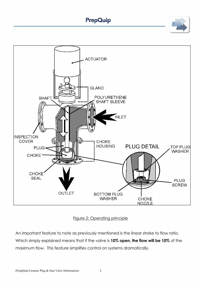
3. Operating principle
Slurry enters the valve at the inlet, and then changes direction by 90 degrees (see
picture). The slurry flows through the valve choke passing the valve plug. The slurry then
exits the valve through the choke nozzle.
An actuator is mounted onto the valve and connected to the valve shaft. On receiving
a control signal the actuator moves the valve shaft forwards or backwards. The plug,
which is connected to the shaft, moves forwards or backwards. This varies the flow
restriction of the slurry through the choke and past the plug. In this way the valve controls
the amount of slurry allowed to pass the plug. This is activated by a control signal
received by the actuator.
(PrepQuip Ceramic Plug & Seat Valve Information) 3
Figure 2: Operating principle
An important feature to note as previously mentioned is the linear stroke to flow ratio.
Which simply explained means that if the valve is 10% open, the flow will be 10% of the
maximum flow. This feature simplifies control on systems dramatically.
(PrepQuip Ceramic Plug & Seat Valve Information) 4
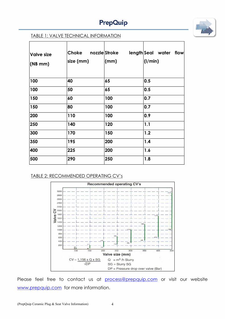
TABLE 1: VALVE TECHNICAL INFORMATION
Valve size
(NB mm)
Choke nozzle
size (mm)
Stroke length
(mm)
Seal water flow
(l/min)
100 40 65 0.5
100 50 65 0.5
150 60 100 0.7
150 80 100 0.7
200 110 100 0.9
250 140 120 1.1
300 170 150 1.2
350 195 200 1.4
400 225 200 1.6
500 290 250 1.8
TABLE 2: RECOMMENDED OPERATING CV’s
Please feel free to contact us at [email protected] or visit our website
www.prepquip.com for more information.