SCRAP MANAGEMENT AND REDESIGNING PLANT LAYOUT · chip Briquettes. This process consists of Hinged...
16
SCRAP MANAGEMENT AND REDESIGNING PLANT LAYOUT 1 Saurav Samrendukumar, 2 Piyush Pulukool, 3 Mitul Chovatiya, 4 Bhavinkumar Prajapati Student, Mechanical department, Laxmi institute of Technology, Sarigam-Valsad. Gujarat Corresponding Author Detail: Saurav Samrendukumar Student, Mechanical department, Laxmi institute of Technology, Sarigam-Valsad, Gujarat. Internal Guide Detail: Mr. Jignesh Chaudhri Assistant Professor, Mechanical department, Laxmi institute of Technology, Sarigam-Valsad. Gujarat. ABSTRACT This Paper focus on the study of machine manufacturing company in Vapi. The Company ‗s main business is to design, develop and deliver the all range of Textile machines. The main problem observed in the company is Scrap in almost parts of company, and it need of Scrap reduction and Plant layout improvement. The reduction of chip can be done by making metal chip Briquettes. This process consists of Hinged steel belt conveyor, shredder machine (metal Chips crusher), Screw conveyor, Briquetting machine. These systems are designed as per the chips capacity of the company so the system is fit to the small scale industries. Now by coming on the Plant layout. Due to high numbers of customer orders, the current production layout has to improve. The objective of this study was to improve the current layout in order to minimize Material handling cost, increase operator safety, improve flexibility for operation, minimize the overall cost and utilize the available area. KEYWORD: Chips, Scrap reduction, conveyors, shredder machine, Briquettes, Plant layout. INTRODUCTION A manufacturing company must have an efficient production system to accomplish its operation. The systems consist of people, equipment and procedure designed for the combination of materials and processes that steer the company‘s operations [1] . In today‘s business, controlling scrap is one factor that companies focus on in order to remain competitive and maximize benefit. Scrap consists of recyclable materials left over from product manufacturing and consumption, such as parts of vehicles, building supplies, and surplus materials. Unlike waste, scrap has monetary value, especially recovered metal from unwanted products and materials [2]. Non metallic materials are also recovered for recycling. Here, we would only concentrate on the metallic scraps produced in the machining and fabrication industries. Day by day, the volume of metallic scrap is increasing due to poor management of manufacturing system and lack of acknowledgement in recycling of metals in the industries [3]. As we all know, in the machining processes, the unwanted material is removed from the work piece to get required product shape. The material is removed using a suitable machine tool for the process. The unwanted materials removed are called as chips International Journal of Scientific Research in Engineering (IJSRE) Vol. 1 (3), March, 2017 IJSRE Vol. 1 (3), March, 2017 www.ijsre.in Page 184
Transcript of SCRAP MANAGEMENT AND REDESIGNING PLANT LAYOUT · chip Briquettes. This process consists of Hinged...

SCRAP MANAGEMENT AND REDESIGNING PLANT LAYOUT 1Saurav Samrendukumar,
2Piyush Pulukool,
3Mitul Chovatiya,
4Bhavinkumar Prajapati
Student, Mechanical department, Laxmi institute of Technology, Sarigam-Valsad. Gujarat
Corresponding Author Detail:
Saurav Samrendukumar
Student, Mechanical department,
Laxmi institute of Technology,
Sarigam-Valsad, Gujarat.
Internal Guide Detail:
Mr. Jignesh Chaudhri
Assistant Professor, Mechanical department,
Laxmi institute of Technology,
Sarigam-Valsad. Gujarat.
ABSTRACT
This Paper focus on the study of machine manufacturing company in Vapi. The Company ‗s
main business is to design, develop and deliver the all range of Textile machines. The main
problem observed in the company is Scrap in almost parts of company, and it need of Scrap
reduction and Plant layout improvement. The reduction of chip can be done by making metal
chip Briquettes. This process consists of Hinged steel belt conveyor, shredder machine (metal
Chips crusher), Screw conveyor, Briquetting machine. These systems are designed as per the
chips capacity of the company so the system is fit to the small scale industries. Now by
coming on the Plant layout. Due to high numbers of customer orders, the current production
layout has to improve. The objective of this study was to improve the current layout in order
to minimize Material handling cost, increase operator safety, improve flexibility for
operation, minimize the overall cost and utilize the available area.
KEYWORD:
Chips, Scrap reduction, conveyors, shredder machine, Briquettes, Plant layout.
INTRODUCTION
A manufacturing company must have an efficient production system to accomplish its
operation. The systems consist of people, equipment and procedure designed for the
combination of materials and processes that steer the company‘s operations [1] . In today‘s
business, controlling scrap is one factor that companies focus on in order to remain
competitive and maximize benefit. Scrap consists of recyclable materials left over from
product manufacturing and consumption, such as parts of vehicles, building supplies, and
surplus materials. Unlike waste, scrap has monetary value, especially recovered metal from
unwanted products and materials [2]. Non metallic materials are also recovered for recycling.
Here, we would only concentrate on the metallic scraps produced in the machining and
fabrication industries. Day by day, the volume of metallic scrap is increasing due to poor
management of manufacturing system and lack of acknowledgement in recycling of metals in
the industries [3]. As we all know, in the machining processes, the unwanted material is
removed from the work piece to get required product shape. The material is removed using a
suitable machine tool for the process. The unwanted materials removed are called as chips
International Journal of Scientific Research in Engineering (IJSRE) Vol. 1 (3), March, 2017
IJSRE Vol. 1 (3), March, 2017 www.ijsre.in Page 184

(Swarf). These chips are not used again for other purposes. Therefore, it is one type of
Metallic Scrap.
In many machining plant, lots of chips are produced on the daily basis. These chips get
collected in the plant without any further use, occupying valuable floor area of the plant. The
Industry then either sells the metal scrap/chips to a third party consumer for low price or will
dump the chips into the environment [4]. In the latter scenario, the chips will cause accidents
and major environmental problem such as pollution, etc. The discarding of waste materials
has a negative environmental impact and is a waste of time and money for the manufacturer.
And similarly, in the former situation, the company acquires less profit by selling the metallic
chips at low cost (by surveying in local markets we get the row M.S. Chips price of per Kg. is
about 14 INR.) to the third party consumers.
Therefore, by looking at both the scenarios, a scrap recycling combined with proper scrap
management technique has been developed to eliminate the ill effects of both scenarios [6]. A
recycling plant is designed which can be used to recycle the metallic chips produced in the
industry by itself. There are many methods to recycle the metal scrap but here we choose to
make metal chip Briquettes which the industries can sell them to other consumers with huge
profit(the price of the briquettes is 3 times more of metal chips).
In manufacturing system, facility layout is considered as one of the important criteria which
has a significant effect towards manufacturing productivity in terms of cost and time [8]. The
objectives of layout are to minimize the material handling cost, improve flexibility for
arrangement and operation, utilize the available area and minimize overall production time.
According to [10] ―a facility layout is an arrangement of everything needed for production of
goods or delivery of services‖. A facility layout is an entity that provides the performance of
any task that include a machine tool, a work centre, a manufacturing cell, a machine shop, a
department and a warehouse. Here we had change the machine shops layout by using 5S
Techniques, (5S Check sheet) according to the Briquetting processes setup.
FISH BONE DIAGRAM
Scrap production
Plant Layout Machining
Manpower
Metal chip production during metal cutting
Inaccurate machining
Untidy workplace
No proper sorting of machines
Human error
Lack of discipline and motivation
Management
No proper disposal of Metal scrap
No proper scrap management
No proper supervision
Figure-1 Fish bone Diagram
International Journal of Scientific Research in Engineering (IJSRE) Vol. 1 (3), March, 2017
IJSRE Vol. 1 (3), March, 2017 www.ijsre.in Page 185

SCRAP MANAGEMENT SYSTEM
It is the system used for recycling the metal chips produced during machining. It mainly
consists of following components: Scrap collector, metal separators, metal compactor, and a
furnace. The system is designed to be as cheap and simple as possible considering the
affordability of the Industry and also considering the skill level of workers available at the
area of the plant.
The different components of the systems are:
HINGED BELT CONVEYORS
Operating
Metallic belt conveyors are used for the transport of chips and metal waste. The liquid and
chips flows on the horizontal part of the carpet. The liquid is recovered at the bottom of the
conveyor, and the chips are taken along by bars in the bucket. The liquid is recovered by
openings on the side or at the bottom of the conveyor. The belt conveyors can be also used in
other fields (ex: sheet falls, parts).
There are various sizes of pitch
• Pitch 25.4: Due to the small direction-change radius especially suited for installation
underneath stamping tool to transport parts and punching.
• Pitch 38.1: For the removal of metal chips, waste material, transport of small parts
and different tasks in the field of material conveyance.
• Pitch 63: For disposal of chips and stamping scrap, transportation of parts and
different transportation problems.
• Pitch 100: For central disposal of chips and stamping scrap and for transport of heavy
loads.
Thus Pitch 63mm is recommended to carry loose metal chips from different machines to
shredder machine.
COMPOSITION
The structure is folded sheet steel and welded bars. For safety, a bonnet cover is placed on the
inclined part of the conveyor and a chute of exit is bolted on the head of the conveyor.
The metallic belt is composed of two chains with metal rollers connected by plates, the whole
assembled by axes pinned at the ends.
A motor gear, with torque limiter, ensures the drive of the carpet
The conveyors can be equipped with:
• adjustable foot support
• chute on horizontal part
• electric safety
• mechanical safety
• tank of liquids recovery
International Journal of Scientific Research in Engineering (IJSRE) Vol. 1 (3), March, 2017
IJSRE Vol. 1 (3), March, 2017 www.ijsre.in Page 186

Specifications
• BELT LENGTH: 25m (25000mm)
• BELT WIDTH: 8" - 36" [25"] (635mm)
• BEGINNING ELEVATION: 8" - 48" [35"] (900mm)
• ENDING ELEVATION: 36" - 126" [80"] (2032mm)
• SPEED: 10 - 45 FPM (2m/min-6m/min)
• INCLINED ANGLE: 30°, 45°, 60° [45°]
• FEEDER LENGTH: 150" - 850" [788"] (20000mm)
• LENGTH OF INCLINE: 52" - 324" [160"] (4047mm)
• NOSEOVER LENGTH: 15" - 120" [61"] (1500mm)
• PIN CHAIN PITCH: 25.4, 38.1, 63, 100 in mm [63mm]
• DRIVE: Standard drive is end drive, overhead, right hand side.
• MOTOR: 1/2 HP through 2 HP. Energy efficient, inverter duty and brake motors also
available. Voltages include 120/1/60, 230/3/60, 460/3/60 and 575/3/60 & DC Voltage.
• SUPPORT CENTERS: Standard supports are on nominal 10‘ centers.
• FRAME FINISH: Standard finish is OSHA safety blue powder. Optional colors
include green, beige, gray, orange, black and yellow.
Figure: 2
International Journal of Scientific Research in Engineering (IJSRE) Vol. 1 (3), March, 2017
IJSRE Vol. 1 (3), March, 2017 www.ijsre.in Page 187
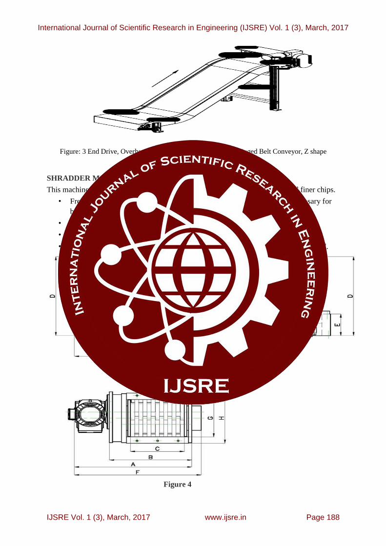
Figure: 3 End Drive, Overhead, Right Hand Side Shbz - Steel Hinged Belt Conveyor, Z shape
SHRADDER MACHINE
This machine is used for shredding (Crushing) long bushy chips into smaller and finer chips.
• Frequently metal chips are bushy and do not satisfy the short category necessary for
briquetting.
• Shredding reduces the space taken by metal chips.
• Long bushy chips may jam the briquetting machine components.
• Shredding increases the bulk density of the metal which is needed to be briquetted.
Figure 4
International Journal of Scientific Research in Engineering (IJSRE) Vol. 1 (3), March, 2017
IJSRE Vol. 1 (3), March, 2017 www.ijsre.in Page 188

Technical Data
Table : 1
WORKING
• The type of shredder in above figure is called rotary metal chip shear shredder.
• This shredder uses shear blades to cut the long bushy metal chips.
• Shear forces act on the metal chips which will exceed the shear strength of the chips.
When the shear forces exceed the ultimate value, the metal fibers break and the shear
action takes place.
• The parameters of shredding depends on the type of material to be shredded, quantity
of shredded metals to be processed, type of feeding given to the shredder, the size of
shredded metal chip required.
SCREW CONVEYOR
A screw conveyor or auger conveyor is a mechanism that uses a rotating helical screw blade,
called a "flighting", usually within a tube, to move granular materials. They are used in many
bulk handling industries. Screw conveyors in modern industry are often used horizontally or
at a slight incline as an efficient way to move semi-solid materials.
They usually consist of a trough or tube containing either a spiral blade coiled around a shaft,
driven at one end and held at the other, or a "shaftless spiral", driven at one end and free at
the other. The rate of volume transfer is proportional to the rotation rate of the shaft. In
industrial control applications the device is often used as a variable rate feeder by varying the
rotation rate of the shaft to deliver a measured rate or quantity of material into a process.
Figure:5
International Journal of Scientific Research in Engineering (IJSRE) Vol. 1 (3), March, 2017
IJSRE Vol. 1 (3), March, 2017 www.ijsre.in Page 189

Selection of Conveyor Size and Speed
In order to determine the size and speed of a screw conveyor, it is necessary first to
establish the material code number. This Code number controls the cross-sectional
loading that should be used.
The capacity table (below) gives the capacities in ft3/hour at one revolution per
minutes for various sized and various cross-sectional loading.
The basis for the Capacity Table is as follows
Where:
C : Capacity [ft3/hour.rpm]
Ds : Diameter of screw [inches]
Dp : Diameter of pipe [inches]
P : pitch of screw, [inches]
K : percent trough loading
In order to determine the conveyor speed can be calculated by the formula:
Where:
N : Conveyor speed [rpm],
(≤ recommended max. Rpm)
Q : Required capacity [ft3/h]
C1 : Conv. Capacity at one rpm (see table below)
CFo : Overload capacity factor [110% - 120%]
CF1 : Conveyor pitch factor
CF2 : Type of flight factor
CF3 : Mixing paddle factor
BRIQUETTING MACHINE
Briquetting is the process in which densification of loose particles occurs. Briquetting process
was mainly started to compress agricultural waste. These wastes were compressed using high
pressure to increase their density and reduce their storage volume. This reduces their storage
volume and cost.
International Journal of Scientific Research in Engineering (IJSRE) Vol. 1 (3), March, 2017
IJSRE Vol. 1 (3), March, 2017 www.ijsre.in Page 190

METAL BRIQUETTING TECHNOLOGY
Metal briquetting is the process of compressing shredded metal chips into small blocks using
high pressure to form briquettes of desired shape. Conventional briquetting processes are
mainly of three types:
1. High pressure compaction
2. Medium pressure compaction assisted by a heating device and
3. Low pressure compaction with a binding agent.
Mainly the selection of the process depends upon the pressure needed to be applied and the
type of material to form briquettes. Here, the material we are dealing with is shredded mild
steel chips. High pressure is required to convert these chips into briquette form of required
shape. Therefore the first method, i.e. High pressure compaction method is selected for metal
briquetting process.
High pressure compaction is of three types:
1. Piston Press briquetting machine
2. Screw type briquetting machine
In piston press briquetting machine, piston is used to apply necessary pressure on the metal
chips to form briquettes. The piston may be mechanically operated or hydraulically operated.
The piston reciprocates in a cylinder and applies pressure using suitable ram design. The ram
forces the material through a die shaped as required.
Advantages of Hydraulically operated piston press over mechanically operated piston press
are:
i. Hydraulic systems can be easily automated.
ii. Ergonomics and aesthetics of hydraulic system is more compared to mechanically
operated system.
iii. More flexible during operation.
iv. Does not require big bulky flywheel technology.
In screw type briquetting machine, a screw mechanism is used to push the feeding material
here, metal chips, into the die. The feeding is constant. The material to be briquetted is
trapped between the casing and the threading of the screw. The diameter of the casing
decreases which increases the pressure between the casing and the thread profile. This
increase in pressure is used for briquetting purposes. The pressure extrudes the metal chips
through the die of required shape.
International Journal of Scientific Research in Engineering (IJSRE) Vol. 1 (3), March, 2017
IJSRE Vol. 1 (3), March, 2017 www.ijsre.in Page 191

PROS AND CONS OF BOTH THE METHODS
PROPERTIES Piston Press Screw Press
Flow of output Step by Step Continuous
Designing procedure Simple Complex
Energy Usage Low High
Maintenance High Low
Briquette Density 1.2 gram/cm3 1.4 gram/cm3
Initial Cost Low High
Wear Less More
Table : 2
Considering the application and cost, we need a mechanism which is less costly and easy to
use. Energy usage should be low enough.
We select the piston press because of its simple construction and design procedure. The main
reason being its less costly compared to screw press and has less energy usage. It is the most
cost effective technology currently used by the Indian market.
PARAMETERS OF A BRIQUETTING PROCESS:
1. Compacting Pressure: It is the most important factor which has to be taken In
consideration. Higher the compacting pressure, stronger will be the briquette generated.
The main advantage of correct pressure is that increase in interlocking forces and
adhesive bonding of the metal particles with each other. Other main advantage is that
briquettes generated with high pressure absorb less humidity from the atmosphere thus
reducing the risk of corrosion of the material due to moisture in the atmosphere.
2. Moisture Content: The moisture on the metal chips should be less than 5 percent.
During briquetting process the temperature of the same increases rapidly. This causes the
water to turn into steam. The steam generated has to escape, which is trapped between the
tightly packed particles after briquetting. This steam which is under high pressure will try
to escape to the surface of the briquette which induces cracks and roughness on the
surface of the briquette. So moisture is an important parameter and should be kept in
limits before briquetting.
3. Pressing Temperature: Optimal pressing temperature should be maintained while
making briquettes. If the temperature is very low, the briquette formed will be of very low
quality. The binding between the material may not be strong enough and the briquette
becomes brittle. When the temperature is higher than optimum value, the volatile
materials in the briquette tends to vaporize and may also burn destroying the quality of
International Journal of Scientific Research in Engineering (IJSRE) Vol. 1 (3), March, 2017
IJSRE Vol. 1 (3), March, 2017 www.ijsre.in Page 192

the briquette. Therefore, by keeping the temperature at optimum value can increase the
quality, life and strength of the briquette.
STRUCTURE AND WORKING OF BRIQUETTING MACHINE
As stated above, we have selected to work with piston press briquetting machine. After
looking at the advantages offered by the hydraulic over mechanical piston press briquetting
machine, we decided to design the hydraulic system for hydraulic press briquetting machine.
The main components of hydraulic briquetting machine are:
i. Hydraulic equipments like hydraulic cylinders, rams, valves, hydraulic pumps and
hydraulic oil.
ii. Compression chambers
iii. Dies
iv. Screw feeders and hoppers
v. Motors for various mechanical power input.
Figure: 6 (a) Figure: 6 (b)
WORKING
The chips collected from the conveyor are dropped into a shear chip shredder. This shredder
cuts down the long and discontinuous chips into finer particles ranging from few millimeters
to 1 cm in length. These shredded chips are then carried to the hopper of the briquetting
machine. The shredded chips after falling into the hopper is needed to be conveyed to the pre
compression chamber. The feeding job is carried out using a screw feeding system as shown
in the figure. The screw feeder carries the shredded chips from the hopper in a uniform
manner. The screw feeder drops the metal chips into pre compression chamber.
In the pre compression, a hydraulic press which is operated using cylinder 1 applies force in
the range of 100KN and compresses the loose chips. This compression stage eliminates any
air trapped between the chips and compact the chips so that it can fit in the main compression
chamber. This initiates mechanical interlocking between the chips. After pre compression the
chips are then compressed using higher compression force in the range of 500 to 900 kN of
International Journal of Scientific Research in Engineering (IJSRE) Vol. 1 (3), March, 2017
IJSRE Vol. 1 (3), March, 2017 www.ijsre.in Page 193

force. This is done using main hydraulic mechanism powered by cylinder 1 as shown in
figure. The chips are forced through a die of required shape using high hydraulic pressure.
The die should be designed to withstand huge temperature changes and pressures. After
pushing the chips through the die, both rams retract. When the ram reaches their TDC , the
screw feeder starts feeding the chips into pre compression chamber again. The same
procedure follows.
The briquette form from the previous cycle may be loosely connected to the die, therefore,
the briquette formed in the current cycle pushes the briquette forward and the briquette comes
out of the die. This applies necessary axial on the die to maintain it‘s required shape.
Necessary support columns are used to support the hydraulic and feeding systems. This
prevents the machine from vibrating and prevents failure due to bending and tensile loading.
HYDRAULIC CIRCUIT USED AND ITS WORKING
The following figure shows the hydraulic circuit used in the briquetting machine. This circuit
uses the sequence valves to control two operations performed in a proper sequence in both
the direction of the DACs. In this example the circuit uses manually operated 4/3 DCV
(Direction Control Valve). This can be made solenoid operated if automation of the
mechanism is required.
Figure: 7
As shown in the figure, the briquetting machine consists of 2 Double Action Cylinders
(DACs). The main cylinder is numbered as 1 and the pre compression cylinder is numbered
as cylinder 2. The extension and retraction of these two cylinders should be in proper
sequence for the working of the briquetting process which is being carried out.
As we have seen, the pre compression takes place first, therefore, the Cylinder 2 should be
extended first and the main cylinder 1 should stay in retracted position. After that the cylinder
2 reaches its end of stroke, the cylinder 1 should extend with greater force so that it can push
the metal chips through the die. The second cylinder should still remain in extended position.
After that, in the third sequence, the main cylinder 1 should retract to it‘s initial position
meanwhile cylinder 2 should maintain its position. In the fourth step, after the full retraction
of the first cylinder, cylinder starts retracting to it‘s initial position.
Ladder diagram shows the proper sequence of the cylinders in an easy manner.
International Journal of Scientific Research in Engineering (IJSRE) Vol. 1 (3), March, 2017
IJSRE Vol. 1 (3), March, 2017 www.ijsre.in Page 194

Here, the sequence valves are used for sequencing both the cylinders as described above. 4/3
valve is used for fluid direction control.
The working of the circuit is as follows:
i. When the DCV is in it‘s first position, the hydraulic fluid flows into cylinder 2. This
extends the ram in cylinder 1.
ii. When the cylinder 2 reaches it‘s end of stroke, the pressure inside this line increases.
The pilot of the first sequence valve V1 senses this change in pressure and connects
the line to cylinder 1. This moves the ram of cylinder 1.
iii. When the DCV is switched to position 2, the pressurized fluid from the pump first
flows into the main cylinder. Port 3. This retracts the ram of the cylinder 1.
iv. When cylinder one is fully retracted, the pressure in the line increases. The pilot of
sequence valve 2 senses this increase in pressure which switches the flow of fluid to
cylinder 2. Port 4. This step retracts the extended ram to its initial position.
v. Then the DCV is again switched to 1st position and the cycle continues.
PLANT LAYOUT REDESIGNING
We choose 5S techniques for Redesigning of existing machine shop layout.
The high chips produced machine ore arranged in a single row for convince of transfer of
chips to shredder machine.
5S TECHNIQUE FOR REDESIGNING THE LAYOUT OF MACHINE SHOP
5S is structured approach to achieving clean and orderly work place by fixing place for
everything in its place. 5s is an abbreviation for the Japanese words seiri, sieton, seiso,
seiketsu and shitsuke.
We have used this quality tool in the machine shop of Yamuna Machine work to improve the
environment and safety in the machine shop. We used 5s to redesign the layout to improve
the productivity and cleanliness of the machine shop.
Japanese words meanings are as follows:
i. Seiri – Getting rid of unnecessary items.
ii. Sieton – arranging items systematically for easy retrieval.
iii. Seiso – keeping work place clean and tidy.
iv. Seiketsu – scheduling regular clearing and clearing out operation.
v. Shitsuke – making all the above tasks meet agreed standard.
International Journal of Scientific Research in Engineering (IJSRE) Vol. 1 (3), March, 2017
IJSRE Vol. 1 (3), March, 2017 www.ijsre.in Page 195

Figure : 8(A) Figure : 8(B)
LITERATURE REVIEW
This literature review will address a number of experimental studies, experimental
Correlations and data reduction publications which focused on the topic Scrap
recycling/reduction and proper scrap management.
S.N. A Rahim said that ―At present of the manufacturing sector, which is at the economic
level, must be made to sustain societies in the high living by industrial societies and able to
increase productivities so that they are able to achieve the same standard of living equally. It
will be a big issue because recycled materials have become very important to environmental.‖
Qiang Zhai view on scrap recycling ―Current manufacturing companies either landfill these
wastes or pay a third party to haul them away, causing both environmental and economic
issues. As widely recognized, recycling these metal chip wastes could enhance the economic
profit and reduce the environmental impact of manufacturing.‖
Many literatures are been observed over Briquettes making Process of different materials
such as Biomass, Saw Dust, Wood chips, Metal chips, etc.
Sr No. Author Conclusions/Findings
1. Roberto Lucci Theory on recycling or refining of metal chips obtained from
machining in automobile industry. Fusion techniques studied are
efficient since it allows obtaining a considerable percentage of
recovered metal. The values close to 90% recovery.
2 Ganapathi K. N.,
Kalathil
Ramachandran
DMAIC (Define, Measure, Analyze, Improve and Control.)
approach is used for scrap reduction in electronic industries.
International Journal of Scientific Research in Engineering (IJSRE) Vol. 1 (3), March, 2017
IJSRE Vol. 1 (3), March, 2017 www.ijsre.in Page 196

3 Qiang Zhai,
Chris Yuan
In the scrap recycling system,
Recycling Metal Chips from Manufacturing Industry through a
Combined Hydrodynamic and Electromagnetic separator instead
of simple magnetic conveyor separator.
4 M. K. Khare Minimization of material and energy wastage also depends
mainly on conditions of material and machine tools. By choosing
proper parameters on the machining operation can reduce the
scrap output. Scrap recycling for metals is the best way to save
energy as well as materials. Chips Briquetting.
5 Sanjay Kumar Total quality management can be used for scrap reduction in a
manufacturing industry and also reduces the production of
unwanted materials during machining process. Stress on metal
recycling is reduced. 5S, Six sigma tools.
6 Sorin T. Teich Lean Management—The Journey from Toyota to Healthcare
7 Matja` Torkar The investigations confirmed that the compaction of the chips is
necessary for a better yield of material in the melting process and
that stainless steel is a valuable source of alloying elements.
8 Sean Dyer cost structure analysis of the recycling process.
Table : 3
PROFIT CALCULATION
The chips Produced per month in the machine shop in the Yamuna industry is about 2,200kg
to 2,800kg. The average taken is 2,500kg per month. The loose chips produced in the
industry is about 30,000kg per year. Loose chips sold to the third party Approx. at rupees 14
per kg.
Therefore, Price of loose chips sold to the third party per month is: 2,500 × 14 = Rs. 35,000/-
The Price of loose chips sold per year is : 35,000 × 12 = Rs. 4,20,000/-
The price of the metal Brequites in the market is about 3 times then the price of loose metal
chips Thus, price of the loose metal chips × 3 ⁞⁞⁞⁞ 14 × 3 = 42 Rupees.
Therefore, Price of Brequites per month is 42 × 2,500 = Rs. 1,05,000/-
Price of Brequites per year is 12 × 1,05,000 =Rs. 1,260,000/-
• Profit per month = Rs. 1,05,000 –Rs. 35,000 = Rs. 70,000/-
• Profit per year = Rs. 1,260,000 – Rs. 4,20,000 = Rs. 8,40,000/-
International Journal of Scientific Research in Engineering (IJSRE) Vol. 1 (3), March, 2017
IJSRE Vol. 1 (3), March, 2017 www.ijsre.in Page 197

Figure : 9
CONCLUSION
As we have already seen that, in today‘s time, the production of large amount of scrap
materials is not only harmful for the industry but also to the environment we live in.
Therefore, by developing this techniques we can reduce the wastage of our valuable resources
(in this case metals like steel, iron, etc). By using metal chip reduction technique in the
Industry, there should not more scraps getting collected in manufacturing plant area.
• The briquette formed is of dimension 100X140 mm
• The volume reduction can be achieved from 10:1 to 15:1. This means that there would be
10 to 15 times less space required than the loose chips. Thereby, reducing storage cost by
10 to 15 times the Initial price.
• The density of the briquette will be 500kg per m^3. The density may be increased or
decreased by increasing or decreasing hydraulic power. This increases the yield of the
material and reduces oxidation of the bulk material. Thereby, the value of briquette is 3
times the value of loose chips.
• Transport cost is readily reduced. Due to volume reduction and definite shape, one can
easily ship these briquettes from one place to other. The number of transport will reduce,
thereby reducing transport cost.
REFERENCE
1. N. M. Z. N. Mohamed and M. K. Khan, ―Decomposition of manufacturing processes”: A
review, International Journal of Automotive and Mechanical Engineering, vol. 5, pp. 545-
560, 2012.
2. Matjaz Torkar. Recycling of Steel Chips, JournalMaterials and technology 44; 2010: 5,
289-292.
International Journal of Scientific Research in Engineering (IJSRE) Vol. 1 (3), March, 2017
IJSRE Vol. 1 (3), March, 2017 www.ijsre.in Page 198

3. A.D. Jayal. Sustainable manufacturing: Modeling and optimization challenges at the
product, process and system levels, CIRP Journal of Manufacturing Science
4. and Technology 2 ; 2010: 44–152.
5. T. Yang, B. A. Peters, and M. Tu, ―Layout design for flexible manufacturing systems
considering single-loop directional flow 2015 Engineering and Technology Publishing
pattenis,‖ European Journal of Operational Research, vol. 164, no. 2, pp. 440-455, 2005.
6. D. Raman, S. V. Nagalingam, and G. C. I. Lin, ―Towards measuring the effectiveness of a
facilities layout,‖ Robotics and Computer— Integrated Manufacturing, vol. 25, no. 1, pp.
191-203, 2009.
7. V. Guley, A. Güzel, A.Jäger, N.Ben Khalif, A.E. Tekkaya, W.Z. Misiolek. Effect of die
design on the welding quality during solid state recycling of AA6060 chips by hot
extrusion, Material Science & Engineering A 574; 2013: 163-175.
8. S. Sujono and R. S. Lashkari, ―A multi-objective model of operation allocation and
material handling system selection in FMS design,‖ International Journal ofProduction
Economics, vol. 105,110. 1, pp. 116-133, 2007.
9. D. Raman, S. Nagalingam, and B. W. Gurd, ―Quantity of material handling equipment--A
queuing theory based approach,‖ Robotics and Computer-Integrated Manufacturing, vol.
25, no. 2, pp. 348-357, 2009.
10. Oberteuffer, J. A. Magnetic Separation: A Review of Principles, Devices, and
Applications, IEEE TRANSACTIONS ON MAGNETICS, VOL. MAG-10N, O. 2, JUNE
1974.
11. J. Miltenburg, ―Setting manufacturing strategy for a factory- Within-a-factory,‖
International Journal of Production Economics, vol. 113, no. 1, pp. 307-323, 2008.
12. Drage D. et al., Method and apparatus for crushing and separating scrap material, United
States Patent 3,885,744. May 25, 1977.
13. Recycling-guided, 2007, http://recycling-guided.com/a/336756/Recycling+-
+It+Just+Makes+Sense.html
14. Holweg M. The genealogy of lean production. J Oper Manag. 2007;25:420–
http://dx.doi.org/10.1016/j.jom.2006.04.001.
15. Implementing 5S Workplace Organization Methodology Programs | White Papers | Lista
16. Hemant Urdhawareshe, (2000) ―The Six Sigma Approach”, Quality & Productivity
Journal, Vol 01, 3rd Quarter, pp 1-6.
17. James R. Evans, James W, Dean JR(2006), ―Total Quality Management”, Organization
International Journal of Scientific Research in Engineering (IJSRE) Vol. 1 (3), March, 2017
IJSRE Vol. 1 (3), March, 2017 www.ijsre.in Page 199