
SCOTTY BlueBox Equipment Manual · SCOTTY BlueBox Equipment Manual All rights reserved. 5 1 Welcome...
36
SCOTTY BlueBox Equipment Manual
Transcript of SCOTTY BlueBox Equipment Manual · SCOTTY BlueBox Equipment Manual All rights reserved. 5 1 Welcome...

SCOTTY BlueBox Equipment Manual

Disclaimer
Copyright SCOTTY Group Austria GmbH. All rights reserved. SCOTTY Group Austria GmbH (SCOTTY) retains copyright in this manual and associated user documentation (the Documentation). The Documentation must not be reproduced or used for any purpose other than intended without written permission. The information provided in the Documentation is believed to be accurate and reliable; however, SCOTTY does not accept responsibility for loss or damage arising out of errors or omissions, and reserves the right to revise the documentation without notice. SCOTTY and its suppliers retain all copyright and other intellectual property rights in the software embedded in and associated with the product described in the documentation (the Software). Some products include software distributed under GNU General Public License (GPL) and other licenses; please contact SCOTTY for further information and source code. By purchasing the product described in the documentation you are granted a limited license to use the Software, provided you do not copy, alter or adapt the Software in any way including decompiling, disassembling or reverse-engineering. No liability for consequential damages. SCOTTY, the SCOTTY logo, TeleporterTM, and BlueBoxTM are Trademarks of SCOTTY.
Microsoft and Windows are registered Trademarks of Microsoft Corporation. Version V1.03 SD208410A This document is under electronic revision control.

SCOTTY BlueBox Equipment Manual
All rights reserved. 3
Table of Contents
1 Welcome .............................................................................................5
1.1 Welcome ............................................................................................................. 5 1.2 About the Manuals .............................................................................................. 6 1.3 Customer Support ............................................................................................... 6
2 Introduction ........................................................................................7
2.1 Scope ................................................................................................................... 7 2.2 System Overview ................................................................................................. 8
3 Operation ............................................................................................9
3.1 Status LEDs .......................................................................................................... 9 3.2 Starting the System ........................................................................................... 10 3.3 Turning Off the System ...................................................................................... 10
4 Installation ........................................................................................ 11
4.1 Mounting Instructions ....................................................................................... 11 4.2 Cooling and Ventilation ..................................................................................... 12 4.3 Electrical Installation ......................................................................................... 12 4.4 Software Configuration ..................................................................................... 12
5 Maintenance ..................................................................................... 13
5.1 Internal Battery Replacement ........................................................................... 13
6 Physical Specifications ................................................................... 15
6.1 Weight and Dimensions .................................................................................... 15 6.2 Outline Drawings ............................................................................................... 16
7 Electrical Interfaces ......................................................................... 19
7.1 Overview............................................................................................................ 19 7.2 Hardware Specification ..................................................................................... 20 7.3 Video Interfaces ................................................................................................ 20 7.4 Audio Interfaces ................................................................................................ 21 7.5 Data Interfaces .................................................................................................. 22 7.6 Other Inputs/Outputs ........................................................................................ 23 7.7 Power Requirements ......................................................................................... 24
8 Connectors and Pin-Outs ............................................................... 25
8.1 Computer USB (Front) ....................................................................................... 26 8.2 Computer USB 1 … 4 .......................................................................................... 26 8.3 Computer LAN 1 … 2 .......................................................................................... 26 8.4 Computer Display Output (DISP) ....................................................................... 27 8.5 Codec Video Input SDI (SDI-IN).......................................................................... 28

SCOTTY BlueBox Equipment Manual
4 All rights reserved.
8.6 Codec Video Input DVI/HDMI/VGA (DVI-IN) ..................................................... 28 8.7 Codec Equipment (EQU) ................................................................................... 29 8.8 System Control (CTRL) ...................................................................................... 30 8.9 Power Input (PWR) ........................................................................................... 31
9 Environmental Specifications ........................................................ 33
9.1 Operation .......................................................................................................... 33 9.2 Storage .............................................................................................................. 33
10 Options ........................................................................................... 35

SCOTTY BlueBox Equipment Manual
All rights reserved. 5
1 Welcome
1.1 Welcome Welcome to the world of advanced communication... welcome to the world of SCOTTY!
SCOTTY provides a unique offering of live HD video, audio, and data communication, live HD video surveillance transmission, and imagery transfer from air, land, and sea – over satellite and terrestrial networks. This package is used by customers around the world to support their border control, intelligence gathering, reconnaissance, surveillance, search and rescue, and other missions which require beyond line-of-sight connectivity and ruggedized/reliable equipment.
SCOTTY is EN9100 certified and has over fifteen years' experience serving customers around the world.
Please find detailed information on our website: www.scottygroup.com

SCOTTY BlueBox Equipment Manual
6 All rights reserved.
1.2 About the Manuals The Equipment Manual describes the hardware aspects of your SCOTTY system, serving as a valuable source of information not only for integrators but also for users.
The Software Manual accompanies the Equipment Manual. It describes the software aspects of your SCOTTY system, and is geared toward the user and administrator.
Both manuals help you take full advantage of your SCOTTY solution. They are not only a comprehensive guide to the operation of the system, they also provide technical details, simple step by step instructions on how to perform the most common applications, and more. We recommend you read the manuals carefully in order to fully benefit from SCOTTY's advanced solutions.
Furthermore, Quick Reference Guides are available describing the basic functionality on a single page – these are suitable for daily use.
1.3 Customer Support The Support section on our website www.scottygroup.com offers help to maximize the functionality of your SCOTTY system.
Choose Downloads to retrieve the latest documents, manuals and software.
Find updated information about our demo numbers to place demonstration and test calls to our demonstration systems.
Find out how to get in contact with our support experts.
Please help our support team provide the best support possible by including the serial number of your SCOTTY unit in all requests.

SCOTTY BlueBox Equipment Manual
All rights reserved. 7
2 Introduction
2.1 Scope This document covers the specifications, including interface control, usage and maintenance of the following component:
SD208106A SCOTTY BlueBox and variants
The SCOTTY BlueBox (fans installed)

SCOTTY BlueBox Equipment Manual
8 All rights reserved.
2.2 System Overview The SCOTTY BlueBox delivers superior full high definition video and audio, even over satellite or other challenging networks with bandwidth constraints and high latency.
The system supports both common videoconference standards and SCOTTY proprietary, highly optimized communication protocols. By providing bi-directional low latency real time communication, unidirectional live video streaming and video recording for store-and-forward applications, many different application requirements can be fulfilled. Parallel data channels enable bidirectional communication of supplementary data and also remote control of cameras and other equipment. The SCOTTY BlueBox is designed for demanding environmental needs.
The platform supports a wide range of video interfaces like Composite, HD-SDI, HDMI, DVI, and VGA with resolutions of up to 1080p60. Highly adaptable audio interfaces support a wide range of signal requirements. Flexible data interfaces support various data sources and sinks to be integrated in the communication system.
The mechanically very robust platform also provides standard PC interfaces like DVI/HDMI, LAN and USB. An internal solid state disk is used for the operating software and is available for storage of user data. The SCOTTY BlueBox is based on a PC platform running Microsoft Windows. The proven SCOTTY Teleporter provides a flexible, highly configurable user interface.
Excellent EMC characteristics allow employment in setups required to fulfill Zone 1 – NATO SDIP 27 Class B (AMSG 788).
SCOTTY sees this platform as a building block for highly adapted, optimized systems; selecting the required hardware and software modules and fitting them into the optimal mechanical structure will result in optimized, small, light and low-power solutions.
SCOTTY BlueBox Equipment Manual
All rights reserved. 9
3 Operation
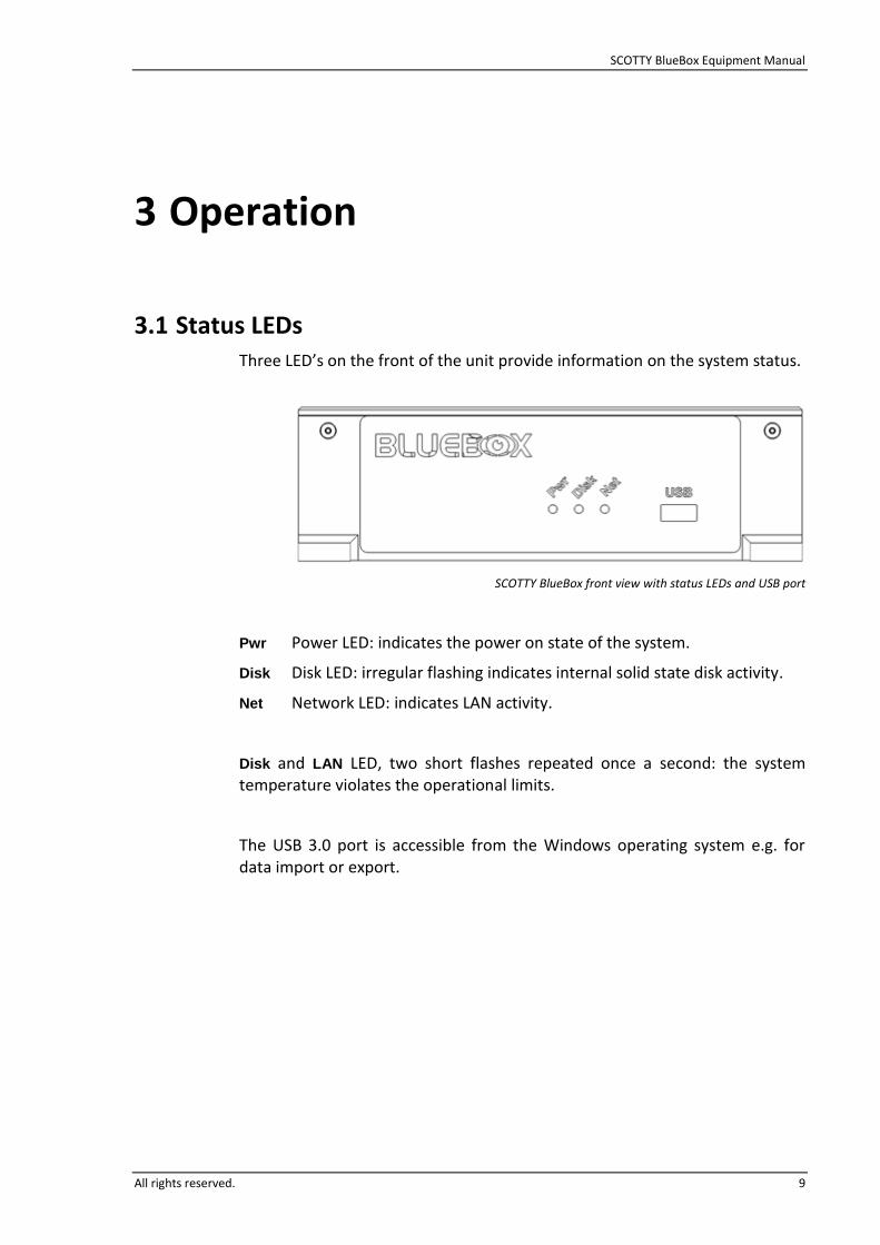
3.1 Status LEDs Three LED’s on the front of the unit provide information on the system status.
SCOTTY BlueBox front view with status LEDs and USB port
Pwr Power LED: indicates the power on state of the system.
Disk Disk LED: irregular flashing indicates internal solid state disk activity.
Net Network LED: indicates LAN activity.
Disk and LAN LED, two short flashes repeated once a second: the system temperature violates the operational limits.
The USB 3.0 port is accessible from the Windows operating system e.g. for data import or export.

SCOTTY BlueBox Equipment Manual
10 All rights reserved.
3.2 Starting the System Typically Autostart is configured - the system starts automatically when power is applied.
As a factory option Manual Power can be configured. In this case an external power button should be available. Push this button to start the unit.
Alternatively, the Label plate on the top of the unit can be used as power button.
Label plate on top of the BlueBox
3.3 Turning Off the System The preferred way to power down the system is to close the software and to shut down Windows; see the Software Manual for details.
The unit can also be turned off with an external power button or the label plate on the top of the unit (see previous chapter). Pushing the button will gracefully shutdown Windows.
Holding the power button for more than four seconds will result in an immediate power off without shutting down Windows first.
If the system is not shut down in the correct fashion, data-loss can occur.

SCOTTY BlueBox Equipment Manual
All rights reserved. 11
4 Installation
4.1 Mounting Instructions The SCOTTY BlueBox is a flange mount unit and can be directly mounted onto the vehicle structure, to a rack, or similar by four M5 metric screws. No shock absorbers are required.
The unit should be installed in a location compatible to its environmental specifications; see the corresponding chapter. It may be mounted in any orientation.
Plan enough room around the unit to allow access to the connectors and for sufficient air flow.
Provisions should be made for a minimum of one mounting hole to be electrically bonded to the mounting frame. The four mounting holes are masked off to ensure adequate electrical contact for grounding purposes.
Secure the mounting screws and/or nuts against self-opening. Please note that screws or nuts are not part of the SCOTTY BlueBox.
For mechanical details, see chapter Physical Specifications.
Caution: Make sure that the structure to which the unit is mounted is thick and strong enough to hold the unit even during shock and vibration.

SCOTTY BlueBox Equipment Manual
12 All rights reserved.
4.2 Cooling and Ventilation The SCOTTY BlueBox requires cooling. Although it will protect itself against overheating, the self-heating power must be dissipated through the mounting structure and/or through air circulation.
On default, the SCOTTY BlueBox comes with two 80mm temperature controlled fans mounted on top of the unit.
Alternatively, the installation of the SCOTTY BlueBox in an environment with sufficient forced air cooling is feasible.
4.3 Electrical Installation The SCOTTY BlueBox gets connected with several interface connectors at the rear side of the unit. Power supply, monitor, keyboard, mouse, headset, Ethernet and more are available on these connectors. In addition an USB 3.0 port is available on the front of the unit, e.g. for data import or data export. For details, see chapter Connectors and Pin-Outs.
The use of shielded cables is highly recommended. Use shielded twisted-pair wiring for all balanced connections, and coax cables with the appropriate impedance.
Before connecting the unit, make sure the power supply matches power requirements (see chapter Power Requirements) and is properly fused.
4.4 Software Configuration To allow optimal operation, the software settings of the SCOTTY BlueBox need to match the electrical installation and the external equipment.
Therefore, especially the codec audio and video settings in the Config Utility and in the Teleport application should be configured as required.
Please refer to the chapter Connectors and Pin-Outs for the signal labels cross-referenced by software and hardware.
For configuration details, please refer to the Software Manual.

SCOTTY BlueBox Equipment Manual
All rights reserved. 13
5 Maintenance
5.1 Internal Battery Replacement The system uses a standard lithium battery for the real time clock. In the event of loss of battery power, the unit will remain functional with the exception of the real time clock. This will result in the wrong date and time stamp on each file created or modified.
Battery replacement is recommended after 24 months.
No tools are required to change the battery. Pushing and sliding the label plate gives access to the battery.
Battery type: Panasonic BR2032
Replace only with a battery of this type and from this manufacturer.
SCOTTY BlueBox battery compartment

SCOTTY BlueBox Equipment Manual
14 All rights reserved.
This page intentionally left blank.

SCOTTY BlueBox Equipment Manual
All rights reserved. 15
6 Physical Specifications
The SCOTTY BlueBox is a compact flange mount unit.
6.1 Weight and Dimensions
Width: 194 mm 7.64”
Length: 326 mm 12.83” (including flanges)
Height: 81 mm
60 mm
3.32”
2.33”
(including fans)
(without fans)
Weight: 3.3 kg
3.1 kg
7.28 lbs
6.83 lbs
(including fans)
(without fans)
Mounting Holes:
Distance: 310 mm / 174 mm 12.2“ / 6.85”
Diameter: 5.5mm 0.21”

SCOTTY BlueBox Equipment Manual
16 All rights reserved.
6.2 Outline Drawings In the following drawings, dimensions are in mm; drawings not to scale.
Outline drawings, side and top view

SCOTTY BlueBox Equipment Manual
All rights reserved. 17
Outline drawings, front and rear view

SCOTTY BlueBox Equipment Manual
18 All rights reserved.
This page intentionally left blank.

SCOTTY BlueBox Equipment Manual
All rights reserved. 19
7 Electrical Interfaces
7.1 Overview The SCOTTY BlueBox provides a rich set of interfaces.
System overview block diagram
Codec (Audio/Video Subsystem)
Computer System
(PC)
System Controller
Power Supply
Video Input DVI/HDMI
4 Audio Inputs
Display DVI/HDMI
Video Input SDI
2 LAN 10M/100M/1G
4 USB 2.0
…
Video Input VGA
Power Input
12V Power Output
Maintenance RS232
2 RS232 + 1 RS422
… 4 Audio Outputs
2 Video Out Analog SD
…
…
Power Button Input Power LED Output
…
Video Input Analog
USB 3.0 (Front)
SCOTTY BlueBox Equipment Manual
20 All rights reserved.
7.2 Hardware Specification The Computer subsystem is based on standard Intel-compatible CPUs.
CPU: Intel® Core™ i7-4650U 2x1.7GHz
RAM: 4 GB
HDD: mSATA-Flash Disk, 250GB
The Codec subsystem is based on a video processing DSP with hardware accelerated encoding and decoding features.
7.3 Video Interfaces Several video inputs to the Codec are available:
One SDI input, compatible with HD-SDI (3Gbit/s SMPTE 292M) and SD-SDI (SMPTE 259M).
One DVI/HDMI input.
One VGA input.
One composite video input.
The display output of the computer system shows the PC desktop, the Teleport software and the video overlay:
DVI/HDMI PC display output
Additional video outputs from the Codec are available, allowing multi-monitor operation:
Two analog SD video outputs, configurable as two composite or one S-Video output.
For a specification of the formats supported, please refer to the Software Manual.

SCOTTY BlueBox Equipment Manual
All rights reserved. 21
7.4 Audio Interfaces Four analog audio inputs are available, featuring a very wide input level range to directly support microphones, line and intercom signal levels:
One 12V balanced microphone input Phantom power 12V over 680Ohm Input range -63,5dBV … +2,3dBV (1.3Vrms)
One electret microphone input Phantom power 3.3V over 2.2kOhm Input range -63,5dBV … +2,3dBV (1.3Vrms) Typically used as headset microphone
Two line inputs Input resistance >8kOhm, symmetrical, AC coupled Differential input, suitable for balanced and unbalanced signals Input range (line, aux) -22dBV … +2,3dBV (1.3Vrms) Input range (microphone) -63,5dBV … +2,3dBV (1.3Vrms) Configurable as one mono or one stereo codec input Configurable to connect an acoustic source (line mode), a playback device (aux mode) or a microphone without phantom power (mic mode)
Four analog audio outputs offer a flexible signal level configuration e.g. to directly connect to audio systems or headsets.
Two speaker outputs Output range -51,5dBV …. 11.2dBV (3.6Vrms), output resistance 10Ohm Configurable as one mono or one stereo codec output

SCOTTY BlueBox Equipment Manual
22 All rights reserved.
One headset output Output range -51,5dBV …. 11.2dBV (3.6Vrms) Output resistance 10 Ohm
One line output Output range -51,5dBV …. 11.2dBV (3.6Vrms) Output resistance 10 Ohm Configurable to connect a speaker (line mode) or a monitoring device (aux mode)
7.5 Data Interfaces Two Windows accessible LAN interfaces are available, enabling videoconferencing, streaming, data transfer or other applications:
10M/100M/1G Ethernet (10/100/1000BASE-T) Auto MDI-X
Five Windows accessible USB interfaces may be used for the connection of keyboard, mouse and other interface or storage equipment:
Four USB 2.0 USB power allows a maximum load of 1A (USB 2.0 standard: 0.5A)
One USB 3.0 (Front) USB power allows a maximum load of 1A (USB 3.0 standard: 0.9A)
Total current of all USB outputs must not exceed 3A
Three Windows accessible serial interfaces are available, useable to connect controllable cameras, GPS receiver or other external equipment:
One RS422/RS485 interface
Two RS232 interfaces, no handshake lines
An additional maintenance RS232 port is available to monitor and control basic system functions independent of the state of the main system.

SCOTTY BlueBox Equipment Manual
All rights reserved. 23
7.6 Other Inputs/Outputs The power button input is only required when the manual start power mode is configured (Factory option). In this case temporarily activating this input by connecting it to ground will start the unit if switched off and shut down the unit when active. Activating the input for more than four seconds will result in an immediate power off. Internally this input is pulled up to 3.3V via a 10kOhm resistor.
A semiconductor relay output provides the same information as the front power LED. The “contacts” are electrically isolated from the power input and from the other system signals. The switching capabilities are 50V, 0.2A.
A typical application of this output is:
The 12V Power Output can be used to supply external equipment. It allows a maximum load of 1.2A.

SCOTTY BlueBox Equipment Manual
24 All rights reserved.
7.7 Power Requirements Nominal voltage: 24V and 28V DC
Voltage range: 20V – 33V
Max. Current: 6A
Power consumption: 45W (typical operation, no external load)
65W (internal maximum, no external load)
95W (typical, with maximum external load)
The system will start immediately when power is applied.
As a factory configuration option “Manual Start” is available: The system will wait for activation via the power button input.
The system will continue to operate normally during short (<100ms) power interruptions. Longer power interruptions may result in loss of unsaved data and normal power up behavior after power is re-applied.
The power inputs are electrically isolated from other system signals.
Under-voltage lockout and temperature monitoring turns off the unit if the power supply voltage or the system temperature violate the operation limits.

SCOTTY BlueBox Equipment Manual
All rights reserved. 25
8 Connectors and Pin-Outs
The SCOTTY BlueBox gets connected via several interface connectors at the rear side of the unit. In addition an USB 3.0 port is available on the front of the unit. For details, see below.
Front interface configuration
Rear interface configuration

SCOTTY BlueBox Equipment Manual
26 All rights reserved.
8.1 Computer USB (Front) Type: USB 3.0 Type A, standard USB 3.0 pinout
Pin Name Signal Description
1 USB7_5V +5V Out
2 USB7_D_N Data-
3 USB7_D_P Data+
4 USB7_GND GND
5 USB7_SSRX_N SuperSpeed Receiver- Computer
6 USB7_SSRX_P SuperSpeed Receiver+ USB (Front)
7 USB7_GND GND
8 USB7_SSTX_N SuperSpeed Transmitter-
9 USB7_SSTX_P SuperSpeed Transmitter+
8.2 Computer USB 1 … 4 Type: USB 2.0 Type A, standard USB 2.0 pinout
Pin Name Signal Description
1 USBx_5V +5V Out
2 USBx_D_N Data- Computer
3 USBx_D_P Data+ USB
4 USBx_GND GND
x indicates the port number (1 … 4)
8.3 Computer LAN 1 … 2 Type: RJ45, standard LAN pinout
Pin Name Signal Description
1 LANx_D0_P BI_DA+, TX+
2 LANx_D0_N BI_DA-, TX-
3 LANx_D1_P BI_DB+, RX+
4 LANx_D2_P BI_DC+ Computer
5 LANx_D2_N BI_DC- LAN
6 LANx_D1_N BI_DB-, RX-
7 LANx_D3_P BI_DD+
8 LANx_D3_N BI_DD-
x indicates the port number (1 … 2)

SCOTTY BlueBox Equipment Manual
All rights reserved. 27
8.4 Computer Display Output (DISP) Type: DVI connector, standard DVI pinout
Pin Name Signal Description
1 HDMI_D2_N Data 2-
2 HDMI_D2_P Data 2+
3 HDMI_SHIELD Shield Data 2
4 Not Connected
5 Not Connected
6 HDMI_DDCCLK DDC SCL
7 HDMI_DDCDAT DDC SDA
9 HDMI_D1_N Data 1-
10 HDMI_D1_P Data 1+ Computer
11 HDMI_SHIELD Shield Data 1 Display Output
12 Not Connected DVI/HDMI
13 Not Connected
14 HDMI_5V DDC +5V Out
15 HDMI_GND GND
16 HDMI_HPDET DDC Hot Plug Detect
17 HDMI_D0_N Data 0-
18 HDMI_D0_P Data 0+
19 HDMI_SHIELD Shield Data 0
20 Not Connected
21 Not Connected
22 HDMI_SHIELD Shield Clock
23 HDMI_CK_P Clock+
24 HDMI_CK_N Clock-
8 VGA_VSYN VGA V-Sync
C1 VGA_R VGA R Computer
C2 VGA_G VGA G Display Output
C3 VGA_B VGA B VGA
C4 VGA_HSYN VGA H-Sync (optional)
C5 VGA_GND GND

SCOTTY BlueBox Equipment Manual
28 All rights reserved.
8.5 Codec Video Input SDI (SDI-IN) Type: BNC 75 Ohm
8.6 Codec Video Input DVI/HDMI/VGA (DVI-IN) Type: DVI connector, standard DVI pinout
Pin Name Signal Description
1 VI10_HDMI_D2_N Data 2- 2 VI10_HDMI_D2_P Data 2+ 3 VI10_HDMI_SHLD Shield Data 2 4 not connected 5 not connected 6 VI10_HDMI_DDCCLK DDC SCL 7 VI10_HDMI_DDCDAT DDC SDA 9 VI10_HDMI_D1_N Data 1- 10 VI10_HDMI_D1_P Data 1+ 11 VI10_HDMI_SHLD Shield Data 1 Codec 12 not connected Video Input 13 not connected DVI/HDMI 14 VI10_HDMI_5V DDC +5V In 15 VI10_HDMI_GND GND 16 VI10_HPDET Hot Plug Detect 17 VI10_HDMI_D0_N Data 0- 18 VI10_HDMI_D0_P Data 0+ 19 VI10_HDMI_SHLD Shield Data 0 20 not connected 21 not connected 22 VI10_HDMI_SHLD Shield Clock 23 VI10_HDMI_CK_P Clock+ 24 VI10_HDMI_CK_N Clock-
8 VI11_AN_VSYN VGA V-Sync C1 VI13_AN VGA R Codec C2 VI11_AN VGA G Video Input C3 VI12_AN VGA B VGA C4 VI11_AN_HSYN VGA H-Sync C5 VI11_AN_GND GND

SCOTTY BlueBox Equipment Manual
All rights reserved. 29
8.7 Codec Equipment (EQU) Type: HD26 female (SCOTTY BlueBox)
HD26 male (Cable)
Pin Name Signal Description
6 AI11_AN_P Mic, HI, Pwr 12V Codec Audio
23 AI11_AN_N Mic, LO, Pwr 12V Input Mic
15 AI11_AN_GND GND (Balanced)
7 AI21_AN_P Headset Mic, Pwr 3.3V Codec Audio
24 AI21_AN_N do not connect Input Headset
16 AI21_AN_GND GND (Electret)
8 AI31_AN_P Line In Left/Mono HI/HOT
25 AI31_AN_N Line In Left/Mono LO/GND 1) Codec
9 AI32_AN_P Line In Right HI/HOT Audio Input
26 AI32_AN_N Line In Right LO/GND 1) Line
18 AI3_AN_GND GND
4 AO11_AN Line Out Codec Audio
13 AO11_AN_GND GND Output Line
21 AO21_AN Headset Speaker Codec Audio
17 AO21_AN_GND GND Output Headset
5 AO31_AN Speaker Left/Mono Codec
22 AO32_AN Speaker Right Audio Output
14 AO3_AN_GND GND Speaker
3 VI21_AN CVBS Codec Video
12 VI21_AN_GND GND Input Composite
2 VO21_SD S-Video Y / CVBS Codec
19 VO22_SD S-Video C / CVBS Video Output
11 VO2_SD_GND GND Analog SD
1 do not connect
10 do not connect Future use
20 do not connect
1) For unbalanced signal source bridge to GND

SCOTTY BlueBox Equipment Manual
30 All rights reserved.
8.8 System Control (CTRL) Type: HD44 female (SCOTTY BlueBox)
HD44 male (Cable)
Pin Name Signal Description
6 COM1_TXD TX-
36 COM1_RXD RX+ Computer
21 COM1_GND GND RS422
5 COM4_TXD TX+ COM1
35 COM4_RXD RX-
20 COM4_GND GND
4 COM2_TXD TxD Computer
34 COM2_RXD RxD RS232
19 COM2_GND GND COM2
3 COM3_TXD TxD Computer
33 COM3_RXD RxD RS232
18 COM3_GND GND COM3
7 MAINT_TXD Maint TxD Maintenance
37 MAINT_RXD Maint RxD RS232
22 MAINT_GND GND
1 OUT1+ Output 1+ Power
31 OUT1- Output 1- LED Output
2 OUT2+ Output 2+ General
32 OUT2- Output 2- Purpose Output
8 IN1 Input 1 Power
23 IN1_GND GND Button Input
38 IN2 Input 2 General
24 IN2_GND GND Purpose Input
40 PWR_12V +12V Out 12V Power
25 PWR_12V_GND GND Output
16 GND GND
17 GND GND
26 GND GND Additional
27 GND GND GND
28 GND GND
29 GND GND
30 GND GND

SCOTTY BlueBox Equipment Manual
All rights reserved. 31
9 do not connect
10 do not connect
11 do not connect
12 do not connect
13 do not connect
14 do not connect Future Use
15 do not connect
39 do not connect
41 do not connect
42 do not connect
43 do not connect
44 do not connect
8.9 Power Input (PWR) Type: FCT F2W2PC (SCOTTY BlueBox)
FCT F2W2SC (Cable)
Pin Name Signal Description
2 PWR Power Input Power Input
1 RTN Power Return

SCOTTY BlueBox Equipment Manual
32 All rights reserved.
This page intentionally left blank.

SCOTTY BlueBox Equipment Manual
All rights reserved. 33
9 Environmental Specifications
9.1 Operation Temperature: -10°C to 45°C
Humidity: 5% to 90%, non-condensing
9.2 Storage Temperature: -40°C to 65°C
Humidity: 5% to 95%, non-condensing
Storage Life: 30 years
An internal standard off-the-shelf button cell lithium battery powers the system clock while the unit is switched off. This battery needs to be replaced periodically. The replacement interval is two years. No tools are required to change the battery.
For further details, see chapter Maintenance.

SCOTTY BlueBox Equipment Manual
34 All rights reserved.
This page intentionally left blank.

SCOTTY BlueBox Equipment Manual
All rights reserved. 35
10 Options
SCOTTY systems feature a rich set of configurable hardware and software options, making it possible to tailor the system to customer needs. This chapter is intended to give a non-exhaustive overview of the possibilities of the SCOTTY BlueBox hardware and software. Please note that some of the optional features may become standard by a future software update.
Different CPU for PC System: e.g. low-power Intel® Atom™ E3827 2x1.75GHz CPU
Up to 16GB RAM (depending on CPU module)
Up do 1TB Flash Disk (or even larger, depending on availability)
Individual pre-installation of PC system, individual software and/or software settings
Wake On LAN / Wake On USB
Power outputs (12V, USB) active even when system is in standby
VGA PC display video output (depending on CPU module)
Extended input voltage range: 10V – 33V
Individual video source configuration (RX or TX) of the video outputs of the Codec
Individual configuration of the audio inputs: Phantom power voltage, impedances, pre-amplifier and sensitivity.
Different configurations of the serial interfaces: up to four RS232 without handshake lines, or two RS422/RS485, or two RS232 with handshake lines, or combinations
Embedded audio on SDI input, DVI/HDMI input and DVI/HDMI output
Additional configurations for the analog video inputs: 2 x S-Video, RGB, composite
Additional configuration for the HD analog video output: RGB
Hardware write-protected disk as required by certain security relevant applications
Video conference, recording, streaming and/or overlay: up to 60 fps progressive

SCOTTY BlueBox Equipment Manual
36 All rights reserved.
Additional standards for video conferencing: SIP, H.239, AAC-LC with 48ksps and stereo up to 128kbps, H.263, FECC
Additional protocols for streaming: RTP, HTTP Live Streaming; other audio protocols and/or other data rates
Free configuration of the power button input and the general purpose input
Free configuration of the power LED output and the general purpose output
Software write-protected system partition, changeable only by administrator
Please contact SCOTTY for further details.