Routine and Winter Maintenance Code · Volume 3 : Management of Health and Safety This Volume deals...
146
TRUNK ROAD MAINTENANCE MANUAL : VOLUME 2 Routine and Winter Maintenance Code Copies available from:- The Stationery Office Ltd The Publications Centre PO Box 276 LONDON SW8 5DT Telephone Orders 0171 873 9090 Fax Orders 0171 873 8200 Email Orders : [email protected] Price £27.00 per copy © Crown Copyright 1999
Transcript of Routine and Winter Maintenance Code · Volume 3 : Management of Health and Safety This Volume deals...

TRUNK ROAD MAINTENANCE MANUAL : VOLUME 2
Routine and Winter Maintenance Code
Copies available from:-
The Stationery Office LtdThe Publications CentrePO Box 276LONDONSW8 5DT
Telephone Orders 0171 873 9090Fax Orders 0171 873 8200Email Orders : [email protected]
Price £27.00 per copy © Crown Copyright 1999

HIGHWAYS AGENCYTRUNK ROAD MAINTENANCE MANUAL : VOLUME 2
ROUTINE AND WINTER MAINTENANCE CODE
Version 2 Amend.No 0 Issue Date Feb '96
CONTENTS
INTRODUCTION
Part 1: ROUTINE MAINTENANCE OF HIGHWAYS
1.1 Routine Maintenance Management1.2 Emergency Procedures1.3 Minor Carriageway Repairs1.4 Footways and Cycle Tracks1.5 Covers, Gratings, Frames and Boxes1.6 Kerbs, Edgings and Pre-formed Channels1.7 Highway Drainage1.8 Motorway Communication Installations1.9 Embankments and Cuttings1.10 Grassed Areas1.11 Hedges and Trees1.12 Sweeping and Cleaning1.13 Safety Fences and Barriers1.14 Fences, Walls, Screens and Environmental Barriers1.15 Road Studs1.16 Road Markings1.17 Road Traffic Signs1.18 Road Traffic Signals1.19 Road Lighting

HIGHWAYS AGENCYTRUNK ROAD AND MAINTENANCE MANUAL : VOLUME 2
ROUTINE AND WINTER MAINTENANCE CODE
Version 2 Amend.No 0 Issue Date Feb '96
CONTENTS (continued)
Part 2: ROUTINE MAINTENANCE OF HIGHWAY STRUCTURES
2.1 Introduction2.2 Retaining Walls and Bridge Substructures2.3 Bridge Superstructures2.4 Components2.5 Subways2.6 Culverts2.7 Sign Signal Gantries, High Masts and Catenary Lighting
Part 3: WINTER MAINTENANCE
3.1 Statement of Service3.2 Introduction, Roles and Communication3.3 Cover for Operational Purposes3.4 Operational Techniques3.5 Use of Winter Maintenance Equipment3.6 Compounds and Depots3.7 Salt3.8 Alternative De-icers3.9 Thermal Mapping3.10 Ice Prediction Systems3.11 Road Weather Forecasting

HIGHWAYS AGENCYTRUNK ROAD MAINTENANCE MANUAL : VOLUME 2
ROUTINE AND WINTER MAINTENANCE CODE__________________________________________________________________________________
Version 2 Amend.No 0 Issue Date Feb '96
INTRODUCTION
CONTENTS
(i) General
(ii) Parts
(iii) List of Principal Abbreviations
(iv) Enquiries
(v) Amendments Summary

Volume 2Introduction__________________________________________________________________________________
Version 2 Amend.No 0 Issue Date Feb '96 I -1
Introduction
(i) General
The Trunk Road Maintenance Manual contains three volumes:
Volume 1 : Highways Maintenance CodeVolume 2 : Routine and Winter Maintenance CodeVolume 3 : Management of Health and Safety
This Volume deals with the routine maintenance of highways, the operational winter maintenance ofthe trunk road network, and the routine maintenance of highway structures. Volume 2 shall be readin conjunction with Volume 1 for bidding, allocation and outturn of funds for routine and wintermaintenance and reimbursement of MA's costs.
In addition, Volume 2 should be read in conjunction with the appropriate Volume of the HighwaysAgency's Design Manual for Roads and Bridges (DMRB).
Volume 2 supersedes:-
(a) TRMM 4/85 Code of Practice for Routine Maintenance of Motorways and All-Purpose TrunkRoads.
(b) The Code of Practice for Routine Maintenance (Blue A4 file) published in 1985.
(c) The Statement of Service and Code of Practice for Winter Maintenance (Orange A4 booklet)published in 1987.
(d) TRMM 4/88 Winter Maintenance: Ice Detection Systems, Thermal Mapping and Road WeatherForecasting.
Version 1 of Volume 2 was originally issued in November 1992. Following a complete review of itscontents, this revised version No. 2, dated February 1996, supersedes the earlier version in its entirety.
As it is a new version, the amendments summary sheet will start from scratch again at Amendment 0,Issue date Feb '96 and Part nos 1 to 3.
(ii) Parts
Volume 2 is split into 3 parts:
Part 1 : Routine Maintenance of Highways.
Part 2 : Routine Maintenance of Structures.
Part 3 : Winter Maintenance.

Volume 2Introduction
___________________________________________________________________________________
Version 2 Amend.No 0 Issue Date Feb '96I -2
(iii) List of Principal Abbreviations used
AA Agent Authority (County, Metropolitan County, Metropolitan Borough or LondonBorough Council)
AADT Annual Average Daily TrafficAPTR All-Purpose Trunk Road
BE Bridges Engineering Division - The Highways Agency
CSS County Surveyors SocietyCHART Computerised Highway Assessment of Ratings and Treatmentscv/d Commercial Vehicles per Day
DA Design Agent (either Agent Authority or Consulting Engineer) DLO Direct Labour OrganisationDMRB Design Manual for Roads and Bridges
EC European CommunityECP Emergency Crossing Point
FO Forecasting Organisation
HA Highways Agency (on behalf of the Secretary of State)
HGV Heavy Goods Vehicle
IHMS1 Integrated Highway Maintenance System - Module 1
LGV Large Goods Vehicle
MA Maintenance Agent (either Agent Authority or Consulting Engineer)
NATS National Structures DatabaseNIS Network Information System - The Highways Agency's Trunk Road Management
Information System
OSD Operations Support Division - The Highways Agency
PI Principal Inspection of Highway StructuresPSTN Public Switched Telephone Network
RMMS Routine Maintenance Management SystemRO Regional Office - The Highways Agency
TRMM Trunk Road Management and Maintenance Notice
WMAM Winter Maintenance Area ManagerWMRM Winter Maintenance Regional Manager

Volume 2Introduction__________________________________________________________________________
Version 2 Amend.No 2 Issue Date Aug '99 I -3
(iv) Enquiries
Enquiries about the content of this Code should be made to:-
Highways Agency NCS Operational Strategy Group Room 5/64 St Christopher House Southwark Street LONDON SE1 OTE (telephone 0171-921-4742)
Enquiries concerning distribution should be made to:-
The Stationery Office The Publications Centre PO Box 276 LONDON SW8 5DT Telephone 0171 873 9090

Volume 2Introduction
___________________________________________________________________________
Version 2 Amend.No 2 Issue Date Aug '99I -4
(v) Amendments Summary
Amendment set Issue Date Part No Chapter No. Section No. Initials Date
0 February 1996 1 to 3 All All
1 April 1998 1 1.15 1.15.1
1.19 1.19.1
2 2.1 Various
2 August 1999 1 1.10 All
1.11 All
1.12 1.12.1
1.19 1.19.1

HIGHWAYS AGENCYTRUNK ROAD MAINTENANCE MANUAL : VOLUME 2
ROUTINE AND WINTER MAINTENANCE CODE________________________________________________________________________________
Version 2 Amend.No 0 Issue Date Feb '96
PART 1 - ROUTINE MAINTENANCE OF HIGHWAYS
CONTENTS
Chapter Page No.
1.1 Routine Maintenance Management
1.1.1 Introduction 1.1 - 11.1.2 Routine Maintenance Management System 1.1 - 11.1.3 Inspection Types 1.1 - 31.1.4 Maintenance Requirements 1.1 - 41.1.5 Safety Inspection Requirements 1.1 - 51.1.6 Safety Patrol Requirements 1.1 - 71.1.7 Detailed Inspection Requirements
Annex 1.1.1 Provision of Integrated HighwaysMaintenance System Module 2/3 Data A1.1 - 1
1.2 Emergency Procedures
1.2.1 General 1.2 - 11.2.2 Response Times 1.2 - 11.2.3 Emergency Facilities 1.2 - 21.2.4 Breakdown of Communication Installations 1.2 - 21.2.5 Accident Pathology 1.2 - 2
Annex 1.2.1 Accident Pathology A1.2 - 1
1.3 Minor Carriageway Repairs
1.3.1 General 1.3 - 11.3.2 Inspection Requirements 1.3 - 11.3.3 Maintenance Requirements 1.3 - 2
1.4 Footways and Cycle Tracks
1.4.1 General 1.4 - 11.4.2 Inspection Requirements 1.4 - 11.4.3 Maintenance Requirements 1.4 - 2
1.5 Covers, Gratings, Frames and Boxes
1.5.1 General 1.5 - 11.5.2 Inspection Requirements 1.5 - 11.5.3 Maintenance Requirements 1.5 - 1

HIGHWAYS AGENCYTRUNK ROAD MAINTENANCE MANUAL : VOLUME 2
ROUTINE AND WINTER MAINTENANCE CODE________________________________________________________________________________
Version 2 Amend.No 2 Issue Date Aug '99
CONTENTS (continued)
Chapter Page No.
1.6 Kerbs, Edgings and Pre-formed Channels
1.6.1 General 1.6 - 11.6.2 Inspection Requirements 1.6 - 11.6.3 Maintenance Requirements 1.6 - 1
1.7 Highway Drainage
1.7.1 General 1.7 - 11.7.2 Piped Drainage Systems 1.7 - 11.7.3 Gullies, Catchpits and Interceptors 1.7 - 21.7.4 Piped Grips 1.7 - 31.7.5 Grips 1.7 - 31.7.6 Ditches 1.7 - 41.7.7 Filter Drains 1.7 - 51.7.8 Culverts 1.7 - 51.7.9 Balancing Ponds 1.7 - 61.7.10 Ancillary Items 1.7 - 71.7.11 Flooding 1.7 - 7
1.8 Motorway Communication Installations
1.8.1 General 1.8 - 11.8.2 Inspection Requirements 1.8 - 21.8.3 Maintenance Requirements 1.8 - 3
1.9 Embankments and Cuttings
1.9.1 General 1.9 - 11.9.2 Inspection Requirements 1.9 - 11.9.3 Maintenance Requirements 1.9 - 1
1.10 Landscape Maintenance (Grassed areas and scrub)
1.10.1 General 1.10 - 11.10.2 Inspection Requirements 1.10 - 21.10.3 Maintenance Requirements 1.10 - 2

HIGHWAYS AGENCYTRUNK ROAD MAINTENANCE MANUAL : VOLUME 2
ROUTINE AND WINTER MAINTENANCE CODE________________________________________________________________________________
Version 2 Amend.No 2 Issue Date Aug '99
CONTENTS (continued)
Chapter Page No.
1.11 Landscape Maintenance (Hedges, trees etc)
1.11.1 General 1.11 - 11.11.2 Inspection Requirements 1.11 - 21.11.3 Maintenance Requirements 1.11 - 3
1.12 Sweeping and Cleaning
1.12.1 General 1.12 - 11.12.2 Inspection Requirements 1.12 - 31.12.3 Maintenance Requirements 1.12 - 3
1.13 Safety Fences and Barriers
1.13.1 General 1.13 - 11.13.2 Inspection Requirements 1.13 - 11.13.3 Maintenance Requirements 1.13 - 1
Annex 1.13.1 Mounting Heights for Safety Fence A1.13 - 1
1.14 Fences, Walls, Screens and Environmental Barriers
1.14.1 General 1.14 - 11.14.2 Inspection Requirements 1.14 - 21.14.3 Maintenance Requirements 1.14 - 2
1.15 Road Studs
1.15.1 General 1.15 - 11.15.2 Inspection Requirements 1.15 - 11.15.3 Maintenance Requirements 1.15 - 2
1.16 Road Markings
1.16.1 General 1.16 - 11.16.2 Inspection Requirements 1.16 - 11.16.3 Maintenance Requirements 1.16 - 1
1.17 Road Traffic Signs
1.17.1 General 1.17 - 11.17.2 Inspection Requirements 1.17 - 11.17.3 Maintenance Requirements 1.17 - 2

HIGHWAYS AGENCYTRUNK ROAD MAINTENANCE MANUAL : VOLUME 2
ROUTINE AND WINTER MAINTENANCE CODE________________________________________________________________________________
Version 2 Amend.No 2 Issue Date Aug '99
CONTENTS (continued)
Chapter Page No.
1.18 Road Traffic Signals
1.18.1 General 1.18 - 11.18.2 Inspection Requirements 1.18 - 11.18.3 Maintenance Requirements 1.18 - 2
1.19 Road Lighting
1.19.1 General 1.19 - 1

Volume 2 Chapter 1.1Part 1 Routine Maintenance Management
Version 2 Amend.No 0 Issue Date Feb '96 1.1 - 1
1.1 Routine Maintenance Management
1.1.1 Introduction
This Part is intended to ensure consistency of standards and value for money in routine maintenancepractice on the trunk road network. It sets out the procedure for and frequency of inspections todetermine what routine maintenance tasks are to be carried out and, in some cases, the manner in whichthey are to be performed on motorways and all-purpose trunks roads (APTRs) for which the HighwaysAgency is responsible as the Highway Authority.
Throughout this Part, reference to trunk roads shall be taken as meaning both motorways and APTRs.
This Part covers areas of activity in which work is generally short term or cyclic and necessary to keepthe highway in good working order. It does not deal with the replacement or renewal of those parts ofthe highway which, over a longer term, become unserviceable because of general wear and tear whichwould properly be dealt with by planned programmes of structural maintenance work. The inspectionprocedures may, however, assist in identifying the need for replacement or renewal under suchprogrammes.
The following activities are covered:
Emergency Procedures;Minor Carriageway Repairs;Footways and Cycle tracks;Covers, Gratings, Frames and Boxes;Kerbs, Edgings and Pre-formed Channels;Highway Drainage;Motorway Communications;Embankments and Cuttings;Grassed Areas;
Hedges and Trees;Sweeping and Cleaning;Safety Fences and Barriers;Fences, Walls, Screens and Barriers;Road Studs;Road Markings;Road Traffic Signs;Road Traffic Signals;Road Lighting.
The general requirements will not be appropriate to all circumstances and there will be instances wherethey will have to be varied to take account of local conditions. Such local variations shall be subject tothe approval of the Highways Agency's Regional Office (RO). Approval will only be given wherethe need for such a variation is clearly justified.
For the purposes of this Part, urban trunk roads are those APTRs with a mandatory speed limit of 40mph or less. Exceptionally there may be lengths of APTR with a higher speed limit and lengths ofmotorway which, for most routine maintenance purposes, have urban characteristics. Urbanmaintenance requirements may then be appropriate to these lengths of road and this should beconsidered as a local variation subject to the agreement of the Highways Agency.
1.1.2 Routine Maintenance Management System
Management procedures for the routine maintenance of highways are implemented by the RoutineMaintenance Management System (RMMS). RMMS enables all inspection and other reports,complaints and third party claims to be assessed in conjunction with the inventory, previousmaintenance actions and other relevant data.

Chapter 1.1 Volume 2Routine Maintenance Management Part 1
Version 2 Amend.No 0 Issue Date Feb '961.1 - 2
As well as being in the interests of good management and safety, the RMMS is necessary in order todeal with claims which may arise as a result of an alleged defect on the highway, sometimes afterremedial action has been taken and there is no longer site evidence of the defect. In this context, a nilrecord is as important as a positive record; experience has shown that oral statements are of little use ontheir own.
While it is generally accepted by the Courts that a public highway can never be in perfect condition atall times, the Highways Agency must be able to show that it is meeting its responsibilities in areasonable manner. An adequate inspection system is an essential part of that requirement.
Computer systems have been developed to cover the two main aspects of the RMMS, namely;
(a) data collection(b) data storage, maintenance and use.
The Highways Agency has contributed towards the cost of installation of a computerised databasesystem in all MA's offices. This allows the interrogation and cross referencing of information collectedand stored. Electronic Data Capture Devices (DCDs) shall be used for site collection of data.
The computerised RMMS has five main components:
(a) Network(b) Inventory(c) Inspections(d) Cyclic Maintenance(e) Works Order Interface
The network to be managed is defined to enable unique identification of any location. The RMMS usesthe CHART referencing system which defines any position on the network by Link, Section number,Chainage and Cross-sectional position.
An item inventory of the highway infrastructure and furniture is an essential part of the RMMS. Theinventory items and details to be collected and stored are detailed in the Highways Agency's RMMSManual. Data Capture Devices (DCD) shall be used for collection of inventory data and down-loadedinto the database system.
Inspection and reporting procedures, actions to be taken and, where appropriate, standards to be met areset out in this Part. The RMMS implements these requirements using standardised records ofinspections which also register subsequent decisions and actions. The same record is used for reportsand complaints from outside sources such as the general public, the police, and motoring organisations. DCDs with standard data capture programs enable consistent recording of inspections using check lists(derived from the Highways Agency's RMMS Manual) which set out the items to be inspected anddefects to be reported.

Volume 2 Chapter 1.1Part 1 Routine Maintenance Management
Version 2 Amend.No 0 Issue Date Feb '96 1.1 - 3
In addition to recording defects identified by inspections, the RMMS records cyclic maintenance worksundertaken in accordance with this Part and prompts subsequent cyclic maintenance as it becomes due.
The works order interface provides the facility to review recorded defects periodically, to group themtogether according to appropriate programmes of work and to interact with works ordering systems ininstructing rectification of the defects.
Features designed into the database also allow assessment of performance by means of audit reports.
Summary RMMS inventory data shall be provided to the Highways Agency annually as detailed inAnnex 1.1.1.
1.1.3 Inspection Types
The motorway and APTR network shall be inspected for the purposes of identifying the need for routinemaintenance tasks to be carried out. The requirements shall apply equally to rural and urban trunkroads. Where a particular interval is specified between inspections, this shall be adhered to as closely aspossible.
All personnel shall be sufficiently responsible and competent for the task and receive suitable training tobe fully conversant with the inspection procedures and safety requirements of the Highways Agency.
In the 17 areas of maintenance activity identified in this Part, 2 types of inspection are required - Safetyand Detailed.
Safety Inspections - are designed to identify those defects which are likely to create adanger to the public and therefore require immediate or urgentattention. They shall normally be mobile inspections carried out fromslow moving vehicles, with the occasional need to proceed on foot, atfrequencies which reflect the importance of a particular road. Additional Safety Inspections may be required in response to reports orcomplaints from the police, other organisations, and the public; as aresult of major incidents; or as a result of extreme weather conditions.
Detailed Inspections - are carried out at less frequent intervals than Safety Inspections and aredesigned primarily to establish programmes of routine maintenancetasks not requiring urgent execution. Requirements for DetailedInspections are set out under the appropriate activity headings.
In addition to these two types of inspection, Safety Patrols are required to supplement SafetyInspections on some roads.

Chapter 1.1 Volume 2Routine Maintenance Management Part 1
Version 2 Amend.No 0 Issue Date Feb '961.1 - 4
1.1.4 Maintenance Requirements
Defects which are identified as a result of Safety or Detailed Inspections, Safety Patrols, or followingother reports and complaints, will fall into two categories:
Category 1 - those which require prompt attention because they represent animmediate or imminent hazard or because there is a risk of shortterm structural deterioration;
Category 2 - all other defects.
Category 1 defects shall be corrected or made safe at the time of inspection, if reasonably practicable. In this context, making safe may constitute displaying warning notices, coning off or fencing off toprotect the public from the defect. If it is not possible to correct or make safe the defect at the time ofinspection, repairs of a temporary or permanent nature shall be carried out as soon as possible and in anycase within a period of 24 hours. Temporary repairs shall be inspected regularly as part of a SafetyInspection and a permanent repair carried out within 28 days.
Category 2 defects shall be repaired within planned programmes of work. The computerised RMMSincludes a facility to assign 3 levels of priority to Category 2 defects. These priorities shall beconsidered, together with access requirements, other works upon the road network, traffic levels and theneed to minimise traffic management, in compiling the programmes of work.
Further Maintenance Requirements applying to specific activities are detailed in the relevant chapters.For several activities these also include requirements for cyclic maintenance.
All action taken, including temporary protective measures and repairs, shall be promptlyrecorded and details retained for a minimum of 6 years.
1.1.5 Safety Inspection Requirements
Safety Inspections are designed to identify defects which constitute an imminent or immediate hazardto the public i.e. Category 1 defects. Whenever such defects are encountered, they shall, if reasonablypracticable, be corrected, made safe or otherwise protected by the inspection personnel before beingreported to the base office at the earliest opportunity with a request for immediate action.
Safety Inspections shall normally be carried out by trained personnel operating as a two person teamfrom a slow moving vehicle. Occasionally, where circumstances require, (e.g. in the case of towncentres, principal shopping areas, subways and footbridges and at complex road junctions), inspectionpersonnel shall proceed on foot either to confirm suspected faults or to complete the Safety Inspection. It may be appropriate to undertake Safety Inspections during off-peak periods or at night in order tominimise traffic disruption and maximise safety of both the inspectors and the public.
Safety Inspection data shall be recorded on DCDs and down loaded onto the RMMS database uponreturn to the base office. It is essential that all inspections, including those showing a nil return, areentered onto the database promptly. Records shall be retained for a minimum of 6 years.
Reports and complaints received from other sources shall be similarly recorded on the database andretained together with details of specific inspections and actions taken.

Volume 2 Chapter 1.1Part 1 Routine Maintenance Management
Version 2 Amend.No 0 Issue Date Feb '96 1.1 - 5
The Safety Inspection record shall include details of the weather conditions, road surface condition andany unusual features of the method of inspection.
Table 1.1.1 assigns inspection priorities (Inspection Categories A, B, and C) to trunk roads.
The frequency of Safety Inspections is determined by the Inspection Category of the road;
Inspection Categories A and B - shall receive a Safety Inspection at intervals of7 days.
Inspection Category C - shall receive a Safety Inspection at intervals of28 days.
Slip roads and link roads within interchanges shall receive Safety Inspections at the same frequency asthe main carriageway of the trunk road.
Certain very vulnerable sites, (e.g. the Severn Bridge and M25 tunnels), may be subject to continuoussurveillance. Any such surveillance which is largely dependent on video monitoring, and is primarilydesigned to allow prompt reaction to traffic incidents, should not be considered as an alternative toSafety Inspections.
1.1.6 Safety Patrol Requirements
The function of Safety Patrols is to supplement Safety Inspections by providing a structured, morefrequent surveillance of the road network to identify obvious hazards (Category 1 defects).
A Safety Patrol shall normally be carried out by a single inspector in a vehicle travelling as slowly asprevailing traffic speeds allow without disruption of traffic flow. Occasionally it may be appropriate forSafety Patrols to be undertaken on foot.
Any hazards which are observed shall if reasonably practical be corrected, made safe or otherwiseprotected and reported to the base office for action, in the same manner as defects discovered by aSafety Inspection. They shall be recorded on the RMMS database as Category 1 defects.
A record shall be made of all Safety Patrols undertaken, including the date, the inspector, the method,and the time that each section of the road was patrolled. These records shall be retained in anappropriate format for a minimum of 6 years; there is no provision for their entry onto the RMMSdatabase (except in the reporting of Category 1 defects).
Safety Patrols shall be undertaken on Inspection Category A roads daily (including weekends and bankholidays) between the weekly Safety Inspections.
Safety Patrols are not normally required on roads in Inspection Category B and C but there may becircumstances in which occasional Safety Patrols are appropriate on one of these roads; a local variationshould be agreed with the RO.
At standard junctions it will generally be unnecessary to patrol both the main carriageway and all theslip roads, but at more complex interchanges it may be necessary to traverse some of the link roads. Aschedule of any link roads and slip roads to receive safety patrols shall be agreed with the RO.

Chapter 1.1 Volume 2Routine Maintenance Management Part 1
Version 2 Amend.No 0 Issue Date Feb '961.1 - 6
InspectionCategory
Motorways All-Purpose Trunk Roads
A All, except Inspection Categories B and C A1 (Birtley to Seaton Burn)A1 (Doncaster By-pass to Scotch Corner)A1 (Beds to Doncaster By-pass)A2 (M25 to M2)A5 (M54 to A49)A14 (M11 to A1)A19 (A174 to A689)A38 (M6 to M1)A40 (M50 to Welsh border)A42 (M1 to M42)A46 (M6 to M40)A102 (London in between A102M)A102MA282A5103 (M56 to M63)
B A1M (Scotch Corner to Birtley)M6 (Cumbria)M41M45M58M65A3MA40MA66MA194M
A1 (A406 to M25)A2 (M25 to A102M)A2 (M2 to Dover)A3 (A31, Guildford to A219, London)A4 (M4, Junction 5 to A406)A10 (M25 to North of Ware Bypass)A11 (M11 to A45)A11 (A12 to A106)A12 (A11, London to A45, Ipswich)A13 (M25 to A1206)A14 (M1 to A1)A14 (Felixtowe to M11)A19 (A689 to Seaton Burn)A20 (M25 to B263)A23 (M23 to Brighton)A27 (Hants, M27 to eastern end of Chichester By-Pass)A27 (Lewes to River Adur)A30 (A312 to A4)A31 (Cadnam to A347/A348 Junction)A34 (M3, Junction 9 to M40, Junction 9)A38 (M5, to Saltash Tunnel)A40 (A40M to M25)A40 (M40 to north of Oxford)A41 (A406 to M25)A56 (M65 to M66)A63 (M62 to Hull)A74 (M6 to Scotland)A127 (A12 to M25)A106 (A11 to A102M)A168/A19 (A1 to A174)A180A312 (A30 to M4)A316 (M25 to A312)A404 (M40 to M3)A405 (M1 to A414)A406A414 (A405 to A1M)A419 (M4 to north of Swindon)
C All except as above
Table 1.1.1 Inspection Priority for Trunk Roads

Volume 2 Chapter 1.1Part 1 Routine Maintenance Management
Version 2 Amend.No 0 Issue Date Feb '96 1.1 - 7
1.1.7 Detailed Inspection Requirements
Detailed Inspections are designed to identify routine maintenance work required on the trunk roadnetwork and to enable efficient programming of that work.
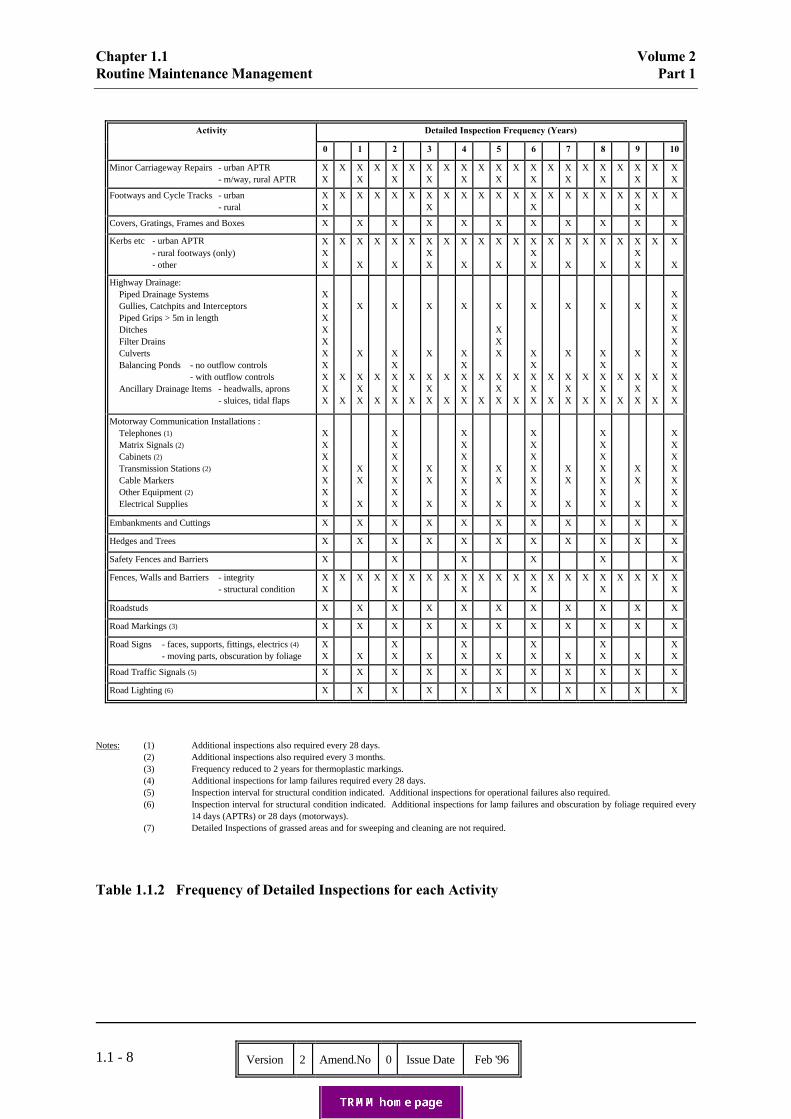
Specific requirements for Detailed Inspection of each activity are set out in Chapters 1.3 to 1.19 and theDepartmental Standards referred to therein. Table 1.1.2 summarises the required frequencies ofDetailed Inspections for each activity.
Arrangements for Detailed Inspection shall seek to minimise disruption to traffic whilst ensuringadequate access for proper inspection and maintaining a safe working environment for the inspectionpersonnel.
Wherever possible, inspections that require lane closures shall be carried out when closures are inoperation for other maintenance work. Where separate lane closures are necessary, inspections shouldbe undertaken in off-peak periods, and consideration given to night-time working or mobile laneclosures to keep traffic delays to a minimum.
Detailed Inspections for defects to items in and along the edges of D3M and D3APTR or wider shouldbe carried out from the hardshoulder or grass verge/nearside lane respectively. The condition of thecarriageway surface, roadstuds and road markings in all lanes should also be observed from theselocations at frequencies laid down for these areas of activity. Additionally, gullies, kerbing and edgingsadjacent to the nearside verge and central reservations should be inspected from these locations at theappropriate frequencies.
At intervals of 2 years (or less if lane closures for other purposes allow or previous expertise hasdemonstrated it to be necessary) a Detailed Inspection shall be carried out from the central reserve withthe offside lane coned off. This inspection shall cover all items within and adjacent to the centralreserve and those items scheduled for inspection at 2 yearly intervals or less. Additionally the centreand offside lanes of the carriageway, as well as the roadmarkings and roadstuds between, shall beinspected.
For D2M and D2APTR inspections from the hardshoulder and grass verge/nearside lane respectivelyshould be adequate for recording defects across the full carriageway width. Offside lane restrictions forthese roads should only be instituted at intervals of 2 years or greater to protect personnel inspectingitems within the central reservation.
Detailed Inspection data shall be collected on DCDs, using standard data capture programs whichinclude check lists setting out the various defects to be noted. The report shall be down loaded onto theRMMS database and retained for a minimum of 6 years.
The Detailed Inspection record shall include details of the manner of inspection (e.g. off-side laneclosure or hard shoulder), the weather conditions and any other unusual features of the inspection. Nilreturns shall also be recorded onto the database.
Chapter 1.1 Volume 2Routine Maintenance Management Part 1
Version 2 Amend.No 0 Issue Date Feb '961.1 - 8
Activity Detailed Inspection Frequency (Years)
0 1 2 3 4 5 6 7 8 9 10
Minor Carriageway Repairs - urban APTR - m/way, rural APTR
XX
X XX
X XX
X XX
X XX
X XX
X XX
X XX
X XX
X XX
X XX
Footways and Cycle Tracks - urban - rural
XX
X X X X X XX
X X X X X XX
X X X X X XX
X X
Covers, Gratings, Frames and Boxes X X X X X X X X X X X
Kerbs etc - urban APTR - rural footways (only)
- other
XXX
X X
X
X X
X
X XXX
X X
X
X X
X
X XXX
X X
X
X X
X
X XXX
X X
X
Highway Drainage: Piped Drainage Systems Gullies, Catchpits and Interceptors Piped Grips > 5m in length Ditches Filter Drains Culverts Balancing Ponds - no outflow controls - with outflow controls Ancillary Drainage Items - headwalls, aprons - sluices, tidal flaps
XXXXXXXXXX
X
X
X
X
XXX
X
X
X
XXXXX
X
X
X
X
XXX
X
X
X
XXXXX
X
X
X
XXX
XXX
X
X
X
XXXXX
X
X
X
X
XXX
X
X
X
XXXXX
X
X
X
X
XXX
X
X
XXXXXXXXXX
Motorway Communication Installations : Telephones (1)
Matrix Signals (2)
Cabinets (2)
Transmission Stations (2)
Cable Markers Other Equipment (2) Electrical Supplies
XXXXXXX
XX
X
XXXXXXX
XX
X
XXXXXXX
XX
X
XXXXXXX
XX
X
XXXXXXX
XX
X
XXXXXXX
Embankments and Cuttings X X X X X X X X X X X
Hedges and Trees X X X X X X X X X X X
Safety Fences and Barriers X X X X X X
Fences, Walls and Barriers - integrity - structural condition
XX
X X X XX
X X X XX
X X X XX
X X X XX
X X X XX
Roadstuds X X X X X X X X X X X
Road Markings (3) X X X X X X X X X X X
Road Signs - faces, supports, fittings, electrics (4)
- moving parts, obscuration by foliage
XX X
XX X
XX X
XX X
XX X
XX
Road Traffic Signals (5) X X X X X X X X X X X
Road Lighting (6) X X X X X X X X X X X
Notes: (1) Additional inspections also required every 28 days.(2) Additional inspections also required every 3 months.(3) Frequency reduced to 2 years for thermoplastic markings.(4) Additional inspections for lamp failures required every 28 days.(5) Inspection interval for structural condition indicated. Additional inspections for operational failures also required.(6) Inspection interval for structural condition indicated. Additional inspections for lamp failures and obscuration by foliage required every
14 days (APTRs) or 28 days (motorways).(7) Detailed Inspections of grassed areas and for sweeping and cleaning are not required.
Table 1.1.2 Frequency of Detailed Inspections for each Activity
Volume 2 Chapter 1.1Part 1 Routine Maintenance Management___________________________________________________________________________________
Version 2 Amend.No 0 Issue Date Feb '96 A1.1 - 1
Annex 1.1.1
Provision of Integrated Highways Maintenance System Module 2/3 Data
Prior to the commencement of the bid cycle within IHMS2/3, summary RMMS Inventory data must beprovided to the Highways Agency through the IHMS data transfer option within the RMMS system. Data must be provided to the Highways Agency by the end of January for inclusion in the biddingprocess.
The resultant data files should be renamed in the following format:
AAAARMNN.DAT
where AAAA represents the Maintenance Agent codeRM represents RMMS Inventory dataNN represents forthcoming financial year
Hence 0100RM95.DAT would represent RMMS Inventory data submitted from Avon County Councilfor forthcoming financial year 1995/96.
The renamed data files should be copied to a 3½" High Density floppy diskette (or equivalent) andshould be clearly labelled:
IHMS Transfer Data - RMMSMaintenance Agent Name, eg. Avon County CouncilContact name and telephone numberData transfer disk createdNumber of disks expected and sequence, eg. Disk 1 of 2
The completed disk(s) should be forwarded to:
Highways Computing Help DeskRoom G04Jefferson House27 Park PlaceLeedsLS1 2SZ
who will acknowledge receipt by return of post. The data received will be loaded by HC onto IHMS2/3and made available for use within 20 working days of its receipt. HC will contact the data supplierwhenever this timescale cannot be achieved.

Volume 2 Chapter 1.2Part 1 Emergency Procedures___________________________________________________________________________________
Version 2 Amend.No 0 Issue Date Feb '96 1.2 - 1
1.2 Emergency Procedures
1.2.1 General
In the event of an emergency occurring on the highway it is essential for maintenance personnel torespond as quickly as possible in order to minimise any danger, disruption or delay to the public. Thissection states the response times to be achieved by MAs in attending emergencies on the trunk roadnetwork.
Information about accidents is frequently required by the Highways Agency to determine liabilities, toreview design standards or to consider maintenance techniques. This section sets out new proceduresfor Accident Pathology - a system of recording details of major incidents promptly, of appropriatedetail and subject matter, to enable analysis for the Highways Agency's particular purposes.
In achieving these response times and levels of service, reliable and efficient communications has a veryimportant role to play. The majority of MAs already operate adequate communication systems. However, some systems may require improvement and/or be augmented with mobile telephones andradio pagers. It will be for the MA to provide any additional equipment required to enable therequirements of this chapter to be met.
Similarly, the MA shall provide suitable plant and equipment, from whatever source, to enable him torespond to the emergency. No specialised or dedicated plant will be provided by the Highways Agency.
1.2.2 Response Times
The Response Time for attendance at an emergency is defined as the time taken from receipt ofnotification of the emergency to commencement of appropriate action at the site of the incident.
Response times should always be as short as practicable but in any event shall not exceed the maximumtimes given in Table 1.2.1. These maximum allowable response times take into account the type of road(Inspection Category as defined in Table 1.1.1) and the time of day.
INSPECTIONCATEGORY(Table 1.1.1)
MAXIMUM RESPONSE TIME
0700 hrs - 1900 hrs 1900 hrs - 0700 hrs
A and B 1 hour 1½ hours
C 1½ hours 2 hours
Table 1.2.1 - Maximum Emergency Response Times

Chapter 1.2 Volume 2Emergency Procedures Part 1___________________________________________________________________________________
Version 2 Amend.No 0 Issue Date Feb '961.2 - 2
The maximum response times may be varied by the Highways Agency in the following circumstances:
(a) On roads carrying over 115,000 vehicles AADT where a rapid build up of traffic canoccur, the Highways Agency may agree a shorter response time with MAs in order tokeep delays to a minimum;
(b) On roads carrying less than 6,000 vehicles AADT the Highways Agency may agree alonger response time with MAs.
1.2.3 Emergency Facilities
Facilities shall be provided by the MA to clear the highway following an accident/spillage, or any otherincident, which requires attendance under emergency conditions.
The MA shall ensure the availability of suitable plant, equipment and personnel to enable him torespond effectively to the emergency, in accordance with the maximum response times stated in 1.2.2.
The MA shall arrange for a suitably qualified member of staff to be on standby 24 hours a day, 7 days aweek. Standby is defined as committed to be available to attend on site without delay, when anemergency arises or when called upon by the Highways Agency.
The MA shall provide the Regional Office with a Method Statement covering all aspects of theprocedures for emergencies and in particular how an emergency response can be initiated.
1.2.4 Breakdown of Communication Installations
The Highways Agency places high priority on the rectification of faults in the motorway communicationsystem and associated electrical equipment. Maintenance of these communication installations is theresponsibility of the specialist contractors appointed directly by the Highways Agency but the MA isresponsible for assisting the specialist contractor in works associated with the repairs.
Breakdown or damage which renders the communications installations inoperable shall be consideredan emergency and the MA shall ensure the availability of resources to give all necessary assistance tothe specialist contractor within the maximum response times stated in Table 1.2.1.
1.2.5 Accident Pathology
New requirements for Accident Pathology are currently being developed in conjunction with PoliceAuthorities. The MA shall not commence implementation of the following procedures untilinstructed to do so by the Regional Office.
Accident Pathology procedures shall be instigated for all accidents involving fatalities on the trunk roadnetwork.
A primary aim of Accident Pathology is to collect, at the time of the accident, information which isunlikely to be available later. Police Authorities will therefore be requested to ensure that MAs areadvised immediately of fatal accidents on their network. The MA shall ensure that lines ofcommunication for this notification are clearly defined by nominating a single point of contact andagreeing this with the Police.

Volume 2 Chapter 1.2Part 1 Emergency Procedures___________________________________________________________________________________
Version 2 Amend.No 0 Issue Date Feb '96 1.2 - 3
It is essential that the MA's representative responds to the incident promptly and neither disrupts thework of the emergency services at the scene nor delays the re-opening of the carriageway. The MA'srepresentative shall therefore attend as soon as possible and in any event within 1 hour ofnotification of the accident; at all times following instructions and directions given by the Police,including arrangements for reaching the site. He shall report immediately to the senior Police officer atthe scene, obtain Police agreement before proceeding with any investigation and comply with anyinstructions given by the Police. The work of the emergency services and the re-opening of thecarriageway shall always take precedence over the MA's investigation.
The level of investigation of an accident shall be determined by a threshold based on the number offatalities and/or serious injuries:
Threshold = No. of + No. of Serious InjuriesFatalities 5
(a) A full investigation shall be undertaken when an accident meets a threshold of 3 ormore.
(b) A preliminary investigation shall be undertaken for all other fatal accidents.
Annex 1.2.1 gives guidance and requirements for a full investigation. This includes information to becollected at the time of the accident and information to gather in subsequent investigation. Thecompleted report shall be forwarded to the RO and to the "officer in the case" at the Police Authoritywithin 2 months of the accident. An interim report shall also be produced and forwarded to the samenominees within 14 days of the accident.
A preliminary investigation shall consist of a photographic record at the time of the accident and abrief description of the incident, with particular emphasis on any unusual features. The MA mustalso ensure that any damaged or failed components of the highway infrastructure are retained. TheMA shall retain the preliminary investigation information pending any requests for furtherinvestigation.
Volume 2 Chapter 1.2Part 1 Emergency Procedures
Version 2 Amend.No 0 Issue Date Feb '96 A1.2 - 1
Annex 1.2.1
Accident Pathology
Full Investigation Report
1. Investigation at the Incident
Information to collect at the time of the accident shall include:
(a) a photographic record of the site (but not of victims).(b) detail photographs (failed components, any unusual features, items with maintenance or
design implications).(c) traffic details, traffic management, details of the approach to the site (including
photographs and preferably a video record).(d) weather conditions (at the time of and prior to the accident).(e) details of unusual aspects of the incident.(f) malfunctioning highway equipment (e.g. lighting, signs).(g) winter maintenance operations in progress, if appropriate.(h) retention of damaged/failed components (by Police or MA).
2. Further Investigation
Information to gather after the incident shall include:
(a) details of the road layout and alignment design.(b) conditions of the highway (including skid resistance tests etc. if appropriate).(c) testing of any components involved if appropriate (e.g. safety fence).(d) copies of press reports(e) police records
3. Police Records
The collection of Police records for the Police report will be co-ordinated by the "officer in the case". MA's should identify this officer at the time of the accident and liaise with him after the event incompiling their investigation report.
4. Report
The MA's report shall comprise a factual account of the accident, including all relevant informationcompiled as discussed above. The report shall also discuss the circumstances of the incident withparticular reference to any implications for highway design or maintenance and consideration of anyaspects for which the Highways Agency might be held liable. The report shall be completed within 2months of the accident and forwarded to the RO and to the "officer in the case" at the Police Authority. An interim report shall also be produced and forwarded to the same nominees within 14 days of theaccident.

Volume 2 Chapter 1.3Part 1 Minor Carriageway Repairs
Version 2 Amend.No 0 Issue Date Feb '96 1.3 - 1
1.3 Minor Carriageway Repairs
1.3.1 General
The requirements of this chapter relate to minor repairs to the carriageway. The requirements do notrelate to larger scale work needed to strengthen the carriageway or to work which would be classed as,or linked to, structural maintenance schemes.
The need to differentiate between routine and structural maintenance activities for work that is similar innature is self-evident. It is usual, before carrying out surface dressing or resurfacing, to ensure that theunderlying road structure is sound. This often requires repairs to potholes, rutting, open joints, etc., thatwould otherwise be carried out as routine maintenance operations, if there was no major structural workfollowing.
The repair of defects reported from inspections may be absorbed into structural repairs already due to becarried out, within the Highways Agency's required timescale. However, structural repairs will usuallybe contained within a long term national programme, determined on the basis of national priorities andthe availability of structural maintenance funds. These schemes sometimes have to be deferred and thismay then make it necessary to carry out the originally identified routine maintenance repairs separatelyand at relatively short notice.
Some minor carriageway repairs may be due to the activities of the utilities or licence holders who aregoverned by the New Roads and Street Works Act 1991. From the 1st January 1993 if the excavation isstill within its guarantee period and fails to meet the performance criteria, as defined in Paragraph S1.2and Chapter S2 of the Specification for the Reinstatement of Openings in Highways(1), the undertakershould be informed of the defect, using the procedure contained in Chapter 4 of the Code of Practice forInspections(2) and the defect inspection procedure invoked. If a dangerous reinstatement is discoveredthe reinstatement should be protected by signing, lighting and guarding and the undertaker's attendancerequested. In exceptional circumstances the reinstatement may be made safe by the MA. Any costsincurred in making safe a reinstatement must be recovered from the undertaker and not charged to theHighways Agency. During the guarantee period of an undertaker's reinstatement, both interim andpermanent, the undertaker remains responsible for its maintenance and performance and the HighwaysAgency's requirements will not apply. However, defects at this stage may well be picked up as a resultof one of the inspection procedures (see 1.1.3).
1.3.2 Inspection Requirements
Detailed Inspections shall be carried out at intervals of 6 months on urban APTRs and at intervals of 1year on motorways and rural APTRs. They shall be coordinated as fully as possible with the detailedinspection of other items in the highway as a whole.
The Highways Agency's RMMS Manual gives guidance on the items to be inspected and defects to benoted. Check lists are also programmed onto the DCDs used to record the inspections, enabling quickreference on site.
Detailed Inspections are designed to note only those types of defects likely to require routinemaintenance rather than to establish general structural condition. They may point to the need to bringforward a CHART or Deflectograph survey.

Chapter 1.3 Volume 2Minor Carriageway Repairs Part 1
Version 2 Amend.No 0 Issue Date Feb '961.3 - 2
1.3.3 Maintenance Requirements
Maintenance Requirements are as stated in 1.1.4.
(1) Specification for the Reinstatement of Openings in Highways - A Code of Practice approved by the Secretaries ofState for Transport, Wales and Scotland under sections 71 and 130 of the New Roads and Street Works Act 1991. HMSO - ISBN 0-11-551143-1.
(2) Code of Practice for Inspections - A Code of Practice issued by the Secretaries of State for Transport, Wales andScotland on behalf of the Highway Authorities and Utilities Committee. HMSO - ISBN 0-11-551148-2.

Volume 2 Chapter 1.4Part 1 Footways and Cycle Tracks
Version 2 Amend.No 0 Issue Date Feb '96 1.4 - 1
1.4 Footways and Cycle Tracks
1.4.1 General
The requirements of this chapter relate to minor repairs to footways and cycle tracks. The requirementsdo not relate to larger scale work which would normally be classed as, or linked to, structuralmaintenance jobs.
A footway is a paved facility for pedestrians, usually within the highway boundary. Footways includethe walking surfaces of subways, underbridges, overbridges and pedestrian rights of way which are theresponsibility of the Highways Agency and which may occasionally fall outside the highway boundary.
A cycle track is a paved facility available for persons with pedal cycles, with or without a right of wayon foot, usually within the highway boundary.
Reference to footways and cycle tracks is made in the Inspection Requirements for CHART surveys. Itshould be noted however that these may not be intended to cover all footways, particularly where theseare remote from the carriageway.
Many footways and cycle tracks adjacent to trunk roads, even in urban areas, have fallen into completeor relative disuse, possibly because of unnecessary provision in the first place or changed circumstanceswith the passage of time. Disused facilities should only be inspected to meet the requirements for SafetyInspections, and maintenance action taken if defects are found that constitute an immediate hazard tohighway users. A little used facility in an urban area may be considered for re-classification as "rural"for maintenance purposes. Where a disused facility represents a significant maintenance liability,consideration should be given to removing it.
Damage to the footways may be caused by vehicle over-riding, particularly in urban areas and at roadjunctions where the footway may be immediately adjacent to the carriageway edge. Considerationshould then be given to the provision of high strength in-situ concrete margins up to 1 m wide behindthe kerb or locally at road junction radii. Alternatively, consideration should be given to carrying out animprovement scheme to alleviate the problem in which case a report and proposal for action should bemade to the Highways Agency.
Pre-cast concrete footway slabs which have superficial cracks only should not be replaced as a routinemaintenance operation unless there is a need to reset the slab because of some other defect.
1.4.2 Inspection Requirements
Detailed Inspections shall be carried out on footways and cycle tracks associated with urban APTRs atintervals of 6 months. Those associated with rural APTR shall be carried out at intervals of 3 years. They shall be coordinated as fully as possible with the Detailed Inspection of other items in the highwayas a whole.
The Highways Agency's RMMS Manual gives guidance on the items to be inspected and defects to benoted. Check lists are also programmed onto the DCDs used to record the inspections, enabling quickreference on site.
Detailed Inspections are designed to note only those types of defect likely to require routinemaintenance rather than to establish general structural condition. They may point to the need to bringforward a CHART survey.

Chapter 1.4 Volume 2Footways and Cycle Tracks Part 1
Version 2 Amend.No 0 Issue Date Feb '961.4 - 2
1.4.3 Maintenance Requirements
Maintenance Requirements are as stated in 1.1.4.
Volume 2 Chapter 1.5Part 1 Covers, Gratings, Frames and Boxes
Version 2 Amend.No 0 Issue Date Feb '96 1.5 - 1
1.5 Covers, Gratings, Frames and Boxes
1.5.1 General
The requirements of this chapter relate to repairs to, and the occasional replacement of, all types ofgratings, covers, frames and boxes that are the direct responsibility of the Highways Agency. Althoughthe requirements do not relate to repairs to items that are the responsibility of other parties, it may benecessary on occasions, if there is a hazard to road users, to make such defects safe and to recover thecosts incurred from the other parties.
The majority of covers are situated in carriageways and footways but those in verges, particularly thoseverges that are likely to be traversed by pedestrians, should not be ignored.
It may often be difficult to decide whether a cracked or broken item is in real danger of collapse. If indoubt, it should be replaced, irrespective of its position.
Defects in covers and gratings may pose particular danger to pedal and motor cycle users. It should beremembered that their occupancy on a carriageway will not always be limited to the nearside lane. Rocking gratings or covers with only small movement under load may nevertheless be a nuisance inurban areas because of the intrusive noise they make. If complaints are received, they should becorrected.
Many covers in carriageways, footways and cycle tracks are the responsibility of the utilities andpossibly other parties. Section 81 of the New Roads and Street Works Act 1991 requires an undertakerto maintain his apparatus in the street to the reasonable satisfaction of the highway authority. If aninspection indicates a hazardous defect, it should be made safe and at the same time the owner should begiven notice to carry out permanent repairs within a specified period depending on both the severity ofthe defect and the effectiveness of action undertaken to make the defect safe. The cost of making safemust be recovered from the undertaker and not charged to the Highways Agency.
1.5.2 Inspection Requirements
Detailed Inspections shall be carried out at intervals of 1 year. They shall be coordinated as fully aspossible with the Detailed Inspection of other items in the highway as a whole, or alternatively, with thecleaning out of highway gullies, catchpits and interceptors.
The Highways Agency's RMMS Manual gives guidance on the items to be inspected and defects to benoted. Check lists are also programmed onto the DCDs used to record the inspections, enabling quickreference on site.
When inspecting the gratings of gullies and other similar surface water catchment items, the opportunityshould be taken to check that the item appears to be functioning satisfactorily and is not, for example,partially or wholly blocked.
1.5.3 Maintenance Requirements
Maintenance Requirements are as stated in 1.1.4.

Volume 2 Chapter 1.6Part 1 Kerbs, Edgings and Pre-formed Channels
Version 2 Amend.No 0 Issue Date Feb '96 1.6 - 1
1.6 Kerbs, Edgings and Pre-formed Channels
1.6.1 General
The requirements of this chapter relate to minor repairs to kerbs, edgings and pre-formed channels of alltypes. The requirements do not relate to larger scale works that would be classed as or linked tostructural maintenance jobs.
Although these items tend to be stable by their nature and construction specification, hazardousconditions can develop quickly when either individual kerbs, or short lengths, are damaged or put out ofalignment by heavy vehicles, or when local subsidence occurs. Frequent damage by heavy vehicles maysuggest the need for local re-alignment or a more robust specification. Short, sometimes isolated,lengths of kerb serving gullies or grips should not be overlooked.
1.6.2 Inspection Requirements
Detailed Inspections shall be carried out at the same frequency as that laid down for the abuttingcarriageway, footway or cycle track. Where a carriageway kerb also abuts a footway or cycle track, thehigher frequency of inspection shall apply.
The Highways Agency's RMMS Manual gives guidance on the items to be inspected and defects to benoted. Check lists are also programmed onto the DCDs used to record the inspections, enabling quickreference on site.
Detailed Inspections are designed to note only those types of defects likely to require routinemaintenance rather than to establish general structural condition. They may point to the need to bringforward a CHART survey.
1.6.3 Maintenance Requirements
Maintenance Requirements are as stated in 1.1.4.

Volume 2 Chapter 1.7Part 1 Highway Drainage
Version 2 Amend.No 0 Issue Date Feb '96 1.7 - 1
1.7 Highway Drainage
1.7.1 General
In determining the Highways Agency's requirements two basic principles have been taken into account:
(a) water reduces safety if allowed to accumulate on the trafficked surfaces of the highway;
(b) the road pavement structure must be adequately drained in order to reduce maintenanceliabilities and realise the design life of the road.
Whilst the effects of (a) are readily observable, those of (b) are not. The inspection procedures andfrequencies laid down in 1.7.2 to 1.7.11 have been designed to allow, as far as possible, a correctassessment of the action that is necessary to keep the highway in a safe condition, and to avoidstructural deterioration of the road pavement.
MAs have a duty to prevent nuisance to adjoining landowners by flooding.
MAs also have a responsibility to ensure that polluted effluent from clearing of highway drainage is notdirected indiscriminately into watercourses.
Any Maintenance Requirements noted in the following paragraphs are in addition to those stated in1.1.4.
1.7.2 Piped Drainage Systems
(a) General
The requirements of this section relate to minor repairs and treatment of defects within all typesof piped drainage systems, including slot drains. Culverts, as defined in 1.7.8, are excluded.
A record of piped drainage systems excluding gully connections, slot drains and piped gripconnections shall be maintained by the MA. The record, preferably in the form of layoutplans, will supplement information held on the RMMS inventory by providing details of piperuns. Ownership of the drainage systems should be established and indicated on the record.
If properly designed and constructed, piped drainage systems should be self-cleansing andmaintenance should only become necessary when a blockage or other fault occurs. Those partsof a system that habitually give trouble should be known to the MA and will need to beinspected more frequently than normal.
Symptoms of blockage or faults that should normally prompt further investigation include:backing up and flooding at the entry points to the piped drainage system; dry outfalls; wetareas on verges; and the presence of lush vegetation.

Chapter 1.7 Volume 2Highway Drainage Part 1
Version 2 Amend.No 0 Issue Date Feb '961.7 - 2
(b) Inspection Requirements
Detailed Inspections of piped drainage systems shall normally be carried out once every10 years unless the need for a greater frequency has been agreed with the Highways Agency asa local variation, or there is evidence of blockage or some other fault noted on safetyinspections, or reports and complaints received from other sources.
Inspections shall be carried out using techniques appropriate to the nature of the drainagesystem. Methods of inspection which may be suitable include:
(i) Pulling a mandrel through the pipe line: This may indicate if a pipe is broken,distorted, silted up or contains roots, but it will not distinguish between these defects;
(ii) Flushing: Flushing pipelines is less informative than using a mandrel but will providethe best method of inspection in areas of subsidence and where the use of a mandrel isnot appropriate;
(iii) Inspection at catchpits and interceptors during or immediately following a period ofprolonged rainfall: Measurement of the depth of water within the entries of pipes, insuccessive catchpits or interceptors along a drain-run will give an indication of whetherthere is any blockage or fault;
(iv) Video inspection: This technique may be appropriate, although its use should generallybe restricted to parts of the network having particular drainage problems.
Maximum use shall also be made of gully, catchpit and interceptor emptying and cleansingoperations, and of their inspection procedures, to check that piped drainage systems areoperating satisfactorily.
1.7.3 Gullies, Catchpits and Interceptors
(a) General
The requirements of this section relate to the removal of silt and other detritus from the traps ofall types of highway gullies, catchpits and interceptors and, so far as possible, to an inspectionof the condition of the items and their operation. They do not relate specifically to theinspection of frames and gratings (chapter 1.5) or to the cleansing of gratings (chapter 1.12),although these operations shall be carried out whenever emptying takes place.
A record of all gullies, catchpits and interceptors should be held on the RMMS database,together with required emptying frequencies.
(b) Inspection Requirements
Detailed Inspections of gullies, catchpits and interceptors shall be carried out at intervals of 1year. They shall be coordinated as far as possible with emptying and cleansing operations and,where applicable, with the detailed inspection of other items in the highway.

Volume 2 Chapter 1.7Part 1 Highway Drainage
Version 2 Amend.No 0 Issue Date Feb '96 1.7 - 3
(c) Maintenance Requirements
Gullies, catchpits and interceptors shall be emptied once per year, although a need for agreater (or lesser) frequency may be established and agreed as a local variation. The frequencyof cleansing of oil interceptors will depend upon their design and location, and should be givenparticular consideration.
Once the frequency of emptying has been decided, the exact timing of the emptying programmeis a matter for determination by the MA, so that local factors can be taken into account as faras possible.
Silt and other solids arising from emptying and cleansing operations pose a potential threat ofpollution and shall be disposed of in an appropriate manner, preferably to licensed tips.
1.7.4 Piped Grips
(a) General
The requirements of this section relate to repairs to piped grips (weirs or offsets), defined asshort lengths of pipe, usually in rural areas, carrying water from a channel across the vergedirect to a ditch, filter drain or soakaway, without a gully-pot, but sometimes with a grating. Where pipe lengths exceed 5 m the requirements in 1.7.2 shall also apply. Gratings, wherefitted, shall be dealt with as set out in 1.7.3 and chapters 1.5 and 1.12.
The importance of piped grips should not be under-estimated. They have often been placed inposition some time after road construction or re-alignment, at known sensitive drainage pointsand therefore deserve regular attention. The connecting pipe is usually laid close to the surfaceand is therefore prone to damage, which may in turn result in blockage. A waterlogged verge isoften an indication of ineffective operation.
(b) Inspection Requirements
No specific Detailed Inspection regime is required for piped grips unless pipe lengths exceed5 m, when the requirements for piped drainage shall apply. An extraordinary inspection maybe required in response to Safety Inspections or other reports of blockage or faults.
(c) Maintenance Requirements
During the execution of cyclic maintenance of gullies, catchpits and interceptors, theopportunity shall be taken to check that piped grips are operating satisfactorily, and, wherenecessary, to carry out maintenance work. This check should include proving, by flushing orjetting with water, that the connecting pipe has sufficient fall and is not blocked.
1.7.5 Grips
(a) General
The requirements of this section relate to repairs to grips, defined as open channels cut acrossrural verges and leading to ditches or filter drains, ending at an appropriate distance from thecarriageway or hard shoulder. The principles set out in 1.7.4 apply equally to grips.
Chapter 1.7 Volume 2Highway Drainage Part 1
Version 2 Amend.No 0 Issue Date Feb '961.7 - 4
(b) Inspection Requirements
No specific Detailed Inspection regime is required for grips. An extraordinary inspection maybe required in response to Safety Inspections or other reports of blockage or faults.
(c) Maintenance Requirements
Grips shall be re-cut cyclically not more frequently than once per year, except where it isagreed with the Highways Agency that a greater frequency is necessary as a local variation. This work should, as far as possible, be coordinated with other cyclic operations such as sidingand gully emptying.
1.7.6 Ditches
(a) General
The requirements of this section relate only to clearing and minor repairs to ditches.
Within the boundaries of motorways, the maintenance of ditches is generally the responsibilityof the Highways Agency, but this may not apply to connecting ditches outside the motorway. In the case of APTRs, ditches along older sections are more likely to be the responsibility ofadjacent landowners or occupiers, while those on more recently constructed lengths (where landhas been specifically purchased for the road), are likely to be the Highways Agency's.
Ditches can become overgrown with vegetation; silted up; blocked with debris, rubbish or bankerosion, to the extent that the flow is impeded. Water in a ditch is not itself harmful unlessstagnation occurs (resulting in a health hazard), flooding is caused, or a resulting higher watertable adversely affects the road or other structural foundations. There can also be the problemof nuisance to adjacent land users.
A record of all ditches is held on the RMMS database, together with required clearingfrequencies.
(b) Inspection Requirements
Detailed Inspections of ditches shall be carried out at intervals of 5 years unless a need for agreater frequency has been agreed with the Highways Agency as a local variation, or there isevidence arising from Safety Inspections of a fault in the intervening period, or reports andcomplaints are received outside the normal inspection procedures. They shall be co-ordinatedas far as possible with clearing operations.
(c) Maintenance Requirements
Ditches, wherever practicable, shall be cleaned out by machine not more frequently than onceevery 5 years. Clearance at more frequent intervals shall be subject to the agreement of theRO as a local variation.

Volume 2 Chapter 1.7Part 1 Highway Drainage
Version 2 Amend.No 0 Issue Date Feb '96 1.7 - 5
1.7.7 Filter Drains
(a) General
The requirements of this section relate to minor repairs to filter drains which may, or may not,incorporate a properly formed invert or collection pipe. If pipes are incorporated therequirements in 1.7.2 shall also apply.
Filter drains act as a drain for surface water run-off from carriageways, hardshoulders, verges,cutting and embankment slopes, and adjacent land. Separately, or in combination, they alsocontrol the ground water level below the road and other structures, adjacent verges and landoutside the highway.
The efficiency of filter drains can be seriously impaired by the formation of a silt crust, withattendant vegetation growth, at the top of the filter material, or by the accumulation of trappedsilt in the lower layers. Each defect can occur with or without the other.
The surface defect can be detected easily by inspection at ground level, but the deeperaccumulations can only be confirmed by excavation, usually by means of trial pits. Where thedrain performs the dual role of surface and sub-surface water collection, ponding at the surfacewill occur if defects are present. If there is no obvious surface defect, ponding will almostcertainly indicate silt in the lower layer.
It is probable that, unless there is an obvious cause for a localised defect, a length of filterdrain will show a consistent defect. The replacement of the filter media, by either new orcleaned existing material, will be a large enough job to warrant a special scheme, which shouldbe part of the normal planned programme of works.
(b) Inspection Requirements
Detailed Inspections of filter drains shall not normally be carried out at the surface morefrequently than once every 5 years, unless the need for a greater frequency has been agreedwith the Highways Agency as a local variation, or there is evidence arising from SafetyInspections of existing or potential blockage or some other fault, or reports and complaints arereceived outside the normal inspection procedures. Detailed inspections of filter drains mayinvolve excavation of trial holes if there is surface evidence of existing or potential blockage orsome other fault.
Maximum use shall be made of gully, catchpit and interceptor emptying and cleansingoperations, and inspection procedures, to check that filter drains are operating satisfactorily.
1.7.8 Culverts
(a) General
The requirements of this section relate only to examination for scour and the maintenance offree flow of water through culverts. Routine maintenance is therefore largely a matter ofinspection and clearance when the need arises.
Larger culverts, as defined in Part 2, shall be inspected and maintained as highway structures,and are outside the scope of this Part.

Chapter 1.7 Volume 2Highway Drainage Part 1
Version 2 Amend.No 0 Issue Date Feb '961.7 - 6
It should be noted that many culverts can tolerate some silting and vegetation growth beforeefficiency is impaired to the point where the culvert should be cleared. Grilles fitted across theends of some culverts are however particularly prone to blockage, restricting free flow of waterthrough the culvert.
(b) Inspection Requirements
Detailed Inspections of culverts shall be carried out at intervals of 1 year, normally afterwinter.
1.7.9 Balancing Ponds
(a) General
The requirements of this section relate to repairs to balancing ponds. They do not relate to anyassociated feeder pipes or ditches, which are covered in 1.7.2 and 1.7.6 respectively.
Balancing ponds and associated feeder pipes, or ditches, are sometimes provided for floodcontrol purposes where the storm run-off from highway surfaces is too rapid to be safely dealtwith by the receiving water courses. This important provision and the need for maintenancecan easily be overlooked, since the ponds are sometimes some distance from the highway. Flooding and/or damage to installations downstream of the pond can be a serious matter andmaintenance should not be neglected.
The effectiveness of balancing ponds can be easily and seriously impaired, so particularattention should be paid to the following possible faults:
(i) blockage of the feeder pipe or ditch;
(ii) silting in the pond causing a loss of storage capacity;
(iii) damage or erosion to the pond banks, walls or bunds;
(iv) damage or obstruction to the pond outlet, which will affect the controlled rate ofdischarge.
A record of all balancing ponds is held on the RMMS database. Specific details of each pond,including capacity and means of access should be added to this record.
Balancing ponds may often become important sites for nature conservation. Prior tocommencing any maintenance of a balancing pond, MAs should consult the RO, to ascertainwhether inspection by an ecologist is required.
(b) Inspection Requirements
Detailed Inspections of balancing ponds with an outflow regulating device shall be carried outat 6 month intervals, once in the spring and once in the autumn, unless it is agreed with theHighways Agency that a greater frequency is necessary as a local variation.
Volume 2 Chapter 1.7Part 1 Highway Drainage
Version 2 Amend.No 0 Issue Date Feb '96 1.7 - 7
Detailed Inspections of balancing ponds with no outflow regulatory device shall be carried outat intervals of 2 years, unless it is agreed with the Highways Agency that a greater frequency isnecessary as a local variation.
1.7.10 Ancillary Items
(a) General
The requirements of this section relate to maintenance and repairs to ancillary drainage itemsincluding headwalls, aprons, sluices, tidal flaps, penstocks, valves and pumps.
A schedule of the more important ancillary items for highways drainage, including all sluices,tidal flaps and pumps, shall be prepared and maintained by the MA.
A complete drainage system may include many ancillary items and these should be inspectedfor erosion damage and operational efficiency. It is particularly important that sluices, tidalflaps and pumps operate as intended because a fault can result in extensive damage andflooding.
(b) Inspection Requirements
Detailed Inspection of headwalls, aprons and the like where associated with culverts, shall becarried out at the same time and at the same frequency as for culverts i.e. at intervals of 1 year. Those associated with piped drainage systems shall be carried out at the same time as pipeddrainage systems (see 1.7.2).
Detailed Inspection of sluices, tidal flaps and the like shall be carried out at intervals of6 months, once in the spring and once in the autumn.
Detailed Inspection of pumps and other specialised equipment shall be carried out inaccordance with the manufacturers' recommendations.
(c) Maintenance Requirements
Maintenance of pumps and other specialised equipment shall be carried out in accordance withthe manufacturers' recommendations.
1.7.11 Flooding
(a) General
The requirements of this section relate to flooding of the highway caused by the inadequateprovision or operation of highway drainage facilities, by abnormally high river and tidal wateror by inadequacies in the non-highway drainage system.
The advantages of an accurate, location referenced inventory system for gullies and otherdrainage items is further highlighted by the problems which are often experienced when dealingwith flooding. Such drainage items are often submerged and may be the cause of flooding. Their easy location will help to speed relief and reduce the extent of the hazard and any relatedinterference with traffic flow, claims and complaints.

Chapter 1.7 Volume 2Highway Drainage Part 1
Version 2 Amend.No 0 Issue Date Feb '961.7 - 8
(b) Inspection Requirements
Additional Safety Patrols (see 1.1.6) shall be undertaken during or immediately after periodsof very heavy/prolonged precipitation to identify areas which may be prone to flooding.
(c) Maintenance Requirements
Where flooding occurs, causing hazardous conditions, the appropriate warning signs shall beplaced in position as quickly as possible.
The cause of the flooding shall be ascertained and given prompt attention, in order to restorethe highway to a reasonable condition. Where it is determined that the flooding is attributableto inadequate infrastructure, given the nature of the weather conditions under which itoccurred, the necessary action to permanently relieve the problem shall be the subject of aprompt report, and proposal for action, to the Highways Agency. If the cause is attributable tothe actions of a third party, the matter should be taken up with them at the earliest opportunity.

Volume 2 Chapter 1.8Part 1 Motorway Communication Installations
Version 2 Amend.No 0 Issue Date Feb '96 1.8 - 1
1.8 Motorway Communication Installations
1.8.1 General
The motorway communications system is a national network providing emergency telephones andsignals on all motorways in England.
The requirements of this chapter relate to the general maintenance of non-specialised electrical plant, itshousings and surroundings, which form part of the system. Maintenance of the specialisedelectrical/electronic plant is undertaken by a specialist contractor under separate contracts let directly bythe Highways Agency and falls outside the scope of this Part, although the duties of the MA includesundertaking the civil engineering works (e.g. cable-laying, traffic management) required to support thespecialist contractor. The borders of responsibility of the MA and the Highways Agency's specialistcontractor at each communications installation site shall be clearly defined and agreed with the RO.
The motorway is a single system in the context of the Electricity At Work Regulations. Beforeundertaking electrical inspections and tests it will be necessary to determine whether the motorwaycommunications supply forms the primary supply or that of a subsystem. The boundaries must beclearly identifiable to all parties before work is undertaken and those responsible for the primary supplyand subsystems must coordinate their activities to ensure that testing is undertaken without risk topersonnel or unplanned disruptions of systems and services.
In the context of motorway communications it must be borne in mind that the systems have a high safetyprofile and provide emergency communications and signalling. The systems are self monitoring and thespecialist maintenance contractors will be called out automatically to attend faults if power isinterrupted. Arrangements must be made to coordinate activities and ensure that disruption is kept to aminimum. This will require coordination with the police and the specialist maintenance contractors. Ifnecessary the RO should be consulted.
A record of all above ground communication installations is held on the RMMS database. In additionthe MA shall maintain record drawings showing the location of communication cable runs andassociated power cables. The MA shall also maintain record drawings giving details of the electricalsupply and distribution to the communications installations. These record drawings shall be reviewedand updated annually and shall be amended whenever the cables are affected by any works.
Accurate records of communications installations are essential to ensure compliance with the Electricityat Work Regulations 1989, particularly in respect of ensuring safe digging practices are followed.
Detailed Inspection requirements for motorway communication installations have to be sufficientlyrigorous to ensure that this emergency service is kept as fully operational at all times as is possible. Thefrequency of inspection, and response times, are therefore more onerous than for the majority of otheritems within this Part.
Although this chapter applies to motorways, increasingly communication installations are beingextended to some parts of the APTR network. The frequencies of the inspection regimes for motorwaysshall be applied equally to APTRs, where these are the responsibility of the MA. The MA shall agree aschedule of communications installations on APTRs with the RO.
Any difficulties experienced in dealing with defects in communication installations shall be referred tothe RO electrical engineer for advice.

Chapter 1.8 Volume 2Motorway Communication Installations Part 1
Version 2 Amend.No 0 Issue Date Feb '961.8 - 2
1.8.2 Inspection Requirements
The Highways Agency's RMMS Manual gives guidance on the items to be inspected and defects to benoted. Check lists are also programmed onto the DCDs used to record the inspections, enabling quickreference on site.
(a) Telephones
Detailed Inspection of all emergency telephone installations shall be carried out at intervals of28 days to ensure that they are accessible, that the telephone housing is correctly aligned andthat the telephone identification number is visible.
The poles and housing shall receive a Detailed Inspection at intervals of 2 years in respect ofstructural condition and surface protective finish.
(b) Matrix Signals
Detailed Inspections of signal lanterns and matrix signals shall be carried out for visibilityincluding the legibility of the signal identification number at intervals of 3 months.
All matrix signals mountings and posts shall receive a Detailed Inspection at intervals of 2years in respect of structural condition and surface protective finish.
(c) Motorway Communication Equipment Cabinets
Detailed Inspections of cabinet sites shall be carried out at intervals of 3 months to check thatdrainage is adequate and installations appear weatherproof, to ensure that paths, steps andhandrails provide safe, unobstructed access and to confirm external identification numbers arepresent. The cabinet doors should not be opened during this inspection.
The cabinets shall receive a Detailed Inspection at intervals of 2 years in respect of structuralcondition and surface protective finish. Normally the cabinet doors should not be opened.
(d) Transmission Station Buildings and Sites
Detailed Inspections of the sites of transmission stations shall be undertaken at intervals of 3months to check for safe access.
Detailed Inspections of all transmission stations shall be carried out externally at intervals of 1year to check structural condition. In particular, attention should be paid to leaking roofs andbadly fitting doors, to the operation of gutters and downpipes, and to accessibility and security(including fences and gates).

Volume 2 Chapter 1.8Part 1 Motorway Communication Installations
Version 2 Amend.No 0 Issue Date Feb '96 1.8 - 3
(e) Communications Cabling
No regular Detailed Inspections of communication cable runs are required.
Detailed Inspections to check the visibility of cable duct markers and cable joint markers shallbe undertaken at intervals of 1 year.
(f) Other Equipment (Variable Message Signs, Fog Detection, Ice Detection, Cameras etc.)
Detailed Inspection of the sites of other equipment shall be undertaken at intervals of3 months to check for safe access.
Detailed Inspections of associated poles and cabinets shall be carried out at intervals of2 years in respect of structural condition and surface protective treatment.
(g) Electrical Supplies
Detailed Inspections of all electrical supplies to communications installations shall be carriedout at intervals of 1 year by a competent person in accordance with the requirements of theInstitution of Electrical Engineers Wiring Regulations and to the approval of the RO.
The MA shall maintain records of all such electrical inspections.
1.8.3 Maintenance Requirements
The following Maintenance Requirements are in addition to those stated in 1.1.4.
Defects to electrical installations which represent an immediate hazard (Category 1 defects) shall beprotected or, whenever possible, made safe at the time of inspection. The defects shall be reported at theearliest opportunity, with a request for immediate action. Such action shall be arranged within theshortest possible time of the notification to the base office and in any case within a period of 24 hours.
Rectification of faults in the communications system due to breakdown or damage is the responsibilityof the Highways Agency's specialist contractor but MAs should note the requirements of 1.2.4 in respectof emergency assistance to be given.

Volume 2 Chapter 1.9Part 1 Embankments and Cuttings
Version 2 Amend.No 0 Issue Date Feb '96 1.9 - 1
1.9 Embankments and Cuttings
1.9.1 General
The requirements of this chapter only relate to inspection regimes and repair timescales for the routinemaintenance of earthworks on trunk roads.
Guidance on failure modes and their identification and procedures for repairs are set out in theHighways Agency's Design Manual for Roads and Bridges, Volume 4, Section 1, HA 48/93,Maintenance of Highway Earthworks and Drainage (HA 48 (DMRB 4.1)).
A record of all embankments and cuttings, including height details, is held on the RMMS database.
Slopes at an early stage of instability can often be recognised by bulging of the slope profile (at thebottom of the potential slip), by development of tension cracks (at the top of the potential slip) or byevidence of water seepage from incipient slip planes. The presence of lush, greener or marsh typevegetation will often serve to identify seepage areas where water is not visible on the surface.
1.9.2 Inspection Requirements
Detailed Inspections of all embankments and cuttings shall be carried out at intervals of 1 year, tocheck for any indication of slippages or rock slides. If evidence is found that the embankment, or thecutting, may be unstable in any way, a further inspection by a geotechnical specialist shall be requestedto confirm the initial findings.
A Detailed Inspection of all embankments and cuttings shall be made by a competent person atintervals of 5 years to check slope stability, in accordance with the guidance given inHA 48 (DMRB 4.1). These inspections shall be programmed, wherever possible, to follow periods ofheavy rain, severe frost, or prolonged dry weather.
1.9.3 Maintenance Requirements
The following Maintenance Requirements are in addition to those stated in 1.1.4.
It is recognised that in cases where geotechnical investigations have to be undertaken and remedialworks designed, it may not be possible to carry out effective permanent repairs within 28 days (see1.1.4). Details of any design and analysis carried out in accordance with HA 48 (DMRB 4.1) will needto be retained for a specified period agreed with the Highways Agency.

Volume 2 Chapter 1.10Part 1 Grassed Areas___________________________________________________________________________
Version 2 Amend.No 2 Issue Date Aug '99 1.10 - 1
1.10 Landscape Maintenance (Grassed areas and scrub)
1.10.1 General
The requirements of this and the following chapter relate to the maintenance of all landscape andecological elements within the Highways Agency’s responsibility, to trees within falling distance of thehighway and to hard surfaced areas that are to be maintained free from vegetation. DMRB Vol 10provides advice on landscape and nature conservation issues. The Landscape Management AdviceNote (DMRB vol. 10A) will give further advice on landscape maintenance when published.
Safety of the highway user is of prime concern but amenity, nature conservation and nuisance toothers must also be considered. The design intention of landscape schemes, ie the landscape andecological functions (formerly landscape objectives), must be taken into account and commitmentsmade in Environmental Statements, at public consultation and at Public Inquiry must be honoured.
Expert advice from landscape managers should be sought to achieve the correct balance betweensafety, amenity, nature conservation and value for money. They will confirm when additional specialistadvice is required. Where landscape management plans exist, they should be used to informmaintenance requirements as part of route management strategies. Where environmental databasesexist they should be consulted before any work is carried out.
Named species and habitats are protected under UK and EC legislation and all highway works mustcomply. Where designated sites lie within or adjacent to the highway boundary, the soft estate shouldbe maintained on the advice of English Nature or local wildlife trusts.
The Highways Agency is developing a Biodiversity Action Plan for the network to protect andenhance species and habitats. This will help to inform maintenance programmes in addition todelivering actions set out in the Government’s species and habitat action plans and in local biodiversityaction plans where they include highway verges.
Legislation requires that English Nature are informed where important habitats and species may beaffected, such as removal of trees used as bat roosts. This should be done well in advance of the workto allow for seasonal factors.
Grassed areas and scrub
Vegetation must not restrict visibility at junctions, access points and bends. Sight lines and minimumstopping distances must be kept clear and signs, lights and marker posts must not be obstructed.Visibility cuts may be required in accordance with the appropriate Technical Directives.
Overhanging vegetation must not obstruct users of the highway or highway personnel carrying outinspections or surveys. One or two cuts a year in the form of a swathe cut may be sufficient tomaintain verges for safety but amenity and nature conservation requirements must also be considered.Edging (siding) may be required on a cyclical basis.
Standards of maintenance should reflect the surrounding landscape. A higher standard of maintenancefor amenity may be appropriate in built-up areas where housing and businesses front the highway andon important "port of entry" routes into England. The cost of removing cuttings may be prohibitivewhen balanced against traffic management but more frequent cutting can reduce costs where this isappropriate.

Chapter 1.10 Volume 2Landscape Maintenance (Grassed Areas and scrub) Part 1
Version 2 Amend.No 2 Issue Date Aug '991.10 - 2
Highway verges that have developed botanical interest or nature conservation value, whether bydesign or through the development of the existing verge over time, should be managed to conserve andenhance the nature conservation value.
Weeds can cause problems if they spread prolifically and control methods may include the use ofherbicides. The Control of Pesticides Regulations 1986 govern the use of pesticides and require thatpersons specifying and applying pesticides hold the appropriate certification.
The Highways Agency is committed to taking a proactive approach to controlling the injurious weedswhich are covered by the Weeds Act 1959 and the Wildlife and Countryside Act 1981. Whereinjurious weeds on highway land are a nuisance to adjacent landowners, it is advisable to work with theadjacent landowner to ensure that weed control measures are undertaken simultaneously to avoidrecontamination across the highway boundary.
Scrub species such as gorse and bramble can become a fire hazard as they mature and their removalmay be necessary on safety grounds. Alternatively, where there is a nature conservation or amenityvalue, the plants may be cut back on a cyclical basis to maintain juvenile growth.
1.10.2 Inspection Requirements
Detailed Inspections
Grassed Areas – biannual inspections as a minimum
1.10.3 Maintenance Requirements
Visibility cuts – one or two cuts per year
Swathe cuts – one or two cuts per year
Grassed areas (including weed control) – to be advised by landscape manager
Injurious weeds – one treatment per year, or as advised by landscape manager

Volume 2 Chapter 1.11Part 1 Landscape Maintenance (Hedges, trees etc)___________________________________________________________________________
Version 2 Amend.No 2 Issue Date Aug '99 1.11 - 1
1.11 Landscape Maintenance (Hedges, trees and planted areas, wetlands and specialecological measures)
1.11.1 General
This chapter includes boundary hedges which remain the responsibility of the Highways Agency,individual street trees and planted areas. It also relates to the maintenance of wetlands for natureconservation and to special ecological measures.
Hedges, trees and planted areas
Where hedges were planted alongside a motorway fence, it was intended that they should be laid andmaintained to produce a stockproof barrier, to replace the fence. This has seldom been carried out andthe options include gaining access from adjacent land to repair the fence or laying and maintaining thehedge.
The Highways Agency is currently exempt from, but acts in the spirit of, the Hedgerow Regulations1997, and where hedgerows are affected by our work, they should be protected. Where a hedgerowor part of a hedgerow has to be removed, it should be replaced and those which would qualify as"important" under the Hedgerow Regulations should be replaced as essential mitigation.
Trees are important for amenity and nature conservation reasons and should be preserved but theycan be a serious hazard to highway users and adjoining land users if they are allowed to becomeunstable. The HA is also responsible for ensuring that trees outside the highway boundary but withinfalling distance are safe; all trees within falling distance are collectively termed “highway trees”.Section 154 of the Highways Act 1980 empowers the HA to deal with hedges, trees and shrubsgrowing on adjacent land and which overhang the highway.
Inspections by highway maintenance personnel during the normal course of inspections can revealevidence of damage to trees or signs of ill health and expert arboricultural advice should then besought. All highway trees require an arboricultural inspection every five years but this period may bereduced on the advice of an arboriculturist.
It is important that arboricultural advice is obtained to advise on the appropriate frquency of inspectionsand works required for each individual street or mature tree. Trees which have to be removed shouldbe replaced as close as possible to the original location. Whilst the HA is currently exempt from treepreservation orders (TPOs), some highway trees may be protected by a TPO and it is advisable toinform the local authority tree officer of intended works.
Planted areas may comprise native trees and shrub species on the inter-urban network, or non-nativespecies in urban areas. Appropriate management techniques including thinning, coppicing and pruningwill be required to achieve the design intention.
For older plots of trees where the original design intention is unknown, expert advice will be required todetermine the most appropriate management techniques for the age and species mix of the plot, takingmeasures to minimise any adverse impacts on adjoining landowners and occupiers. In particular,thinning must be carried out with care where plots perform a screening function or have natureconservation value.

Chapter 1.11 Volume 2Landscape Maintenance (Hedges, trees etc) Part 1
Version 2 Amend.No 2 Issue Date Aug '991.11 - 2
Legislation requires that English Nature are informed where important habitats and species may beaffected, such as the removal of trees used as bat roosts. This should be done well in advance of thework to allow for seasonal factors. It is also advisable to inform the local authority or local residents inadvance of works to remove trees. In some cases there may be other authorities which requirenotification before any work takes place.
Pest control
New planting schemes may be vulnerable to animal damage and will require protection. It is importantthat protection measures are maintained for as long as they are required. Rabbits are of particularconcern to farmers on adjacent land. The Highways Agency is not covered by legislation, notably thePests Act 1954, but the HA should take a proactive approach and work with adjacent landowners tocarry out control methods simultaneously. The Highways Agency is not obliged to provide fencing toprevent rabbits moving onto adjacent land or to prevent recontamination across the highway boundaryand the correct solution will be determined by site-specific requirements and value for money.
Plant diseases can cause extensive damage and expert advice will be required to determine theappropriate methods of control. Diseased plant material must be disposed of in accordance withhorticultural best practice and, where a disease is notifiable, in accordance with MAFF'srecommendations.
Wetlands
Drainage ditches and balancing ponds are increasingly being developed for their nature conservationvalue and maintenance must be carried out using techniques timed to be the least damaging to the floraand fauna. Expert advice from an ecologist should be sought to determine the correct methods andtiming of maintenance works. Even where nature conservation was not a design objective, waterbodies may develop nature conservation value. In cases where there has been no ecological surveysince the last maintenance operation was carried out, or there has been no regular ecologicalinspection, the advice of an ecologist should be sought.
Special ecological measures
The HA has installed fencing to prevent deer and other animals crossing the highway, it has alsoprovided measures such as badger tunnels and bat boxes, often as essential mitigation. Thesemeasures must be maintained so that they continue to be effective and meet the HA’s commitments.Expert advice from an ecologist should be sought to determine the correct techniques and the timing ofmaintenance works. Where the HA is committed to monitoring special ecological measures, monitoringmust be carried out by ecologists with the correct specialist knowledge.
Hard surfaced areas
Vegetation should be removed from areas of the highway such as hard central reserves by methodswhich are appropriate for the location, in accordance with the Control of Pesticide Regulations 1986.In areas where mechanical methods cannot be used for reasons of safety, herbicide applications maybe the most cost effective method of control.

Volume 2 Chapter 1.11Part 1 Landscape Maintenance (Hedges, trees etc)___________________________________________________________________________
Version 2 Amend.No 2 Issue Date Aug '99 1.11 - 3
1.11.2 Inspection Requirements
Hedges, trees and planted areas – twice a year as a minimum; inspections of highway trees should beannual with arboricultural inspections at least every five years.
Wetlands – twice a year, or as advised by ecologist
Special ecological measures – twice a year, or as advised by ecologist
1.11.3 Maintenance Requirements
Pest control - as advised by landscape manager
Hedges and trees and planted areas – as advised by landscape manager; highway tree works to beadvised by arboriculturist
Wetlands – as advised by ecologist
Special ecological measures – as advised by ecologist

Volume 2 Chapter 1.12Part 1 Sweeping and Cleaning___________________________________________________________________________
Version 2 Amend.No 2 Issue Date Aug '99 1.12 - 1
1.12 Sweeping and Cleaning
1.12.1 General
Under the provisions of the Environmental Protection Act 1990: Code of Practice on Litter andRefuse, responsibility for the cleaning and sweeping of APTRs is transferred from MAs to district andborough councils. Sweeping and cleaning of motorways, and the APTRs listed in Table 1.12.1, willremain the responsibility of the Highways Agency and will continue to be dealt with by MAs.
Road No. Description
A2 From its junction with the M2 Motorway (Junction 1) to its junction with theM25 Motorway (Junction 2).
A282 From its junction with the M25 Motorway (Junction 30) to its junction with theM25 Motorway (Junction 2).
A27 From the southern end of the A3(M) to its junction with the M27 Motorway(Junction 13).
A40(M) From its junction with the A40 trunk road (Westway) to its junction with theA5 Edgware Road.
A56 From its junction with the M66 Motorway to its junction with the M65Motorway (Junction 8).
A5103 From its junction with the M56 Motorway (Junction 3) to its junction with theM63 Motorway (Junction 9).
Table 1.12.1 All-Purpose Trunk Roads with Retained Litter Clearing Duties
Sweeping and cleaning of APTRs listed in Table 1.12.2 has been transferred back to the Secretary ofState under Section 86(11) of the Act. Highways Agency has contracted out the sweeping andcleaning of these roads to Design Build Finance and Operate (DBFO) concessionaires.
The requirements of this chapter relate to the Highways Agency's responsibility under theEnvironmental Protection Act for the sweeping and cleaning of all channels and hardshoulders,clearing and removal of debris from traffic lanes, hardshoulders, verges and central reservations,removal of litter, and footway and cycle track sweeping.
It should be noted that there is nothing in the Environmental Protection Act that removes theresponsibility of the Highways Agency to keep trunk roads safe for the travelling public. There will,therefore, be a continuing need for sweeping to be carried out by the Highways Agency's MAs(eg. dealing with shed loads, spillages and accident debris).

Chapter 1.12 Volume 2Sweeping and Cleaning Part 1
Version 2 Amend.No 2 Issue Date Aug '991.12 - 2
Road No. Description
A1 From a point 350 metres south of its junction with the Great North Road atAlconbury to a point 280 metres north of the Fletton Parkway Interchange.
A1 From a point 520 metres south of the Old Great North Road at Micklefield toa point 1 kilometre north of the A64(T) Leeds Road.
A14 From a point 420 metres south east of its junction with Rusts Lane to itsjunction with the A1 trunk road.
A19 From its juntion with the A168 road at Thirsk to the roundabout at the junctionwith the A185 county road immediately south of the southern entrance to theTyne Tunnel.
A30 From its junction with the M5 Motorway (Junction 29) to its juntion with theA35 trunk road at Honiton.
A35 From its juntion with the A30 trunk road at Honiton to the western leg of theroundabout at the junction of A35 and A31 trunk roads north east of BereRegis.
A50 From the boundary between the City of Stoke on Trent and the Borough ofStafford at the junction with the A521 county road to the junction with theA516 trunk road.
A66 From its junction with the A19 trunk road to a point 265 metres east of theoverbridge to Teeside Retail Park in Stockton on Tees Borough Council.
A69 From its junction with the M6 Motorway (Junction 43) to its junction with theA1 trunk road (West Road Interchange).
A168 From a point 350 metres east of the county road overbridge located 650metres east of the A1(M) bridge over the eastbound carriageway of the A168trunk road at Dishforth to its junction with A19 trunk road at Thirsk.
A174 From its junction with the A19 trunk road at Parkway Interchange to thejunction with the A1053 trunk road.
A417 From its junction with the A419 trunk road to the grade separated junction atOrdnance Survey Grid Reference 388500E, 217600N near M5 (Junction11a).
A419 From its junction with the M4 Motorway (Junction 15) to its junction with theA417 trunk road.
A1053 From its junction with the A174 trunk road to its junction with the A1085county road at Grangetown.
Table 1.12.2 All-Purpose Trunk Roads with Litter Clearing Dutiescontracted to DBFO concessionaires

Volume 2 Chapter 1.12Part 1 Sweeping and Cleaning___________________________________________________________________________
Version 2 Amend.No 2 Issue Date Aug '99 1.12 - 3
1.12.2 Inspection Requirements
No Detailed Inspections shall be carried out and reliance shall be placed on the regular SafetyInspections and Safety Patrols (see Chapter 1.1) to decide when any special action needs to be taken.
1.12.3 Maintenance Requirements
The following Maintenance Requirements are in addition to those stated in 1.1.4.
Hardshoulders, verges, channels, central reservations and slopes shall be swept and scavenged as theneed arises in order to achieve the standards of cleanliness set out in the Environmental Protection Act1990: Code of Practice on Litter and Refuse. To achieve these standards the Highways Agencyshould respond to the accumulation of litter in a pro-active rather than a re-active way. This can beachieved best by a combination of programmed scavenges, as need dictates, to establish the overallcleanliness standard, and "black spot" scavenges in locations where the highway has become heavilylittered as a result of other factors such as debris from vehicles or wind blown litter. If a particularsource of wind blown litter can be identified then the owners should be requested to control their sitemore effectively.
Dealing with weed and vegetation growth in channels, which is likely to obstruct the flow of water orcause structural deterioration, does not fall within the scope of the Environmental Protection Act. Suchgrowth should be treated in accordance with section 1.10.1(e).
Footways and cycle tracks associated with those APTR's listed in Table 1.12.1 shall be swept as theneed arises but not more frequently than once per year unless it is agreed with the RO that a greaterfrequency is necessary as a local variation.
Litter bins should be provided only at designated picnic sites and those lay-bys with toilets and/or picnictables. Such sites that are the responsibility of the Highways Agency shall be scavenged as necessary.
Debris encountered by inspectors and other maintenance personnel in traffic lanes and onhardshoulders, and which constitutes an immediate hazard, shall be removed immediately, if reasonablypractical. Otherwise road users shall be protected as far as possible. As a minimum, the aim should beto display notices warning of the hazardous conditions, before reporting at the earliest opportunity witha request for immediate action. Such action shall be completed within the shortest possible time, and inall cases within 24 hours.

Volume 2 Chapter 1.13Part 1 Safety Fences and Barriers
Version 2 Amend.No 0 Issue Date Feb '96 1.13 - 1
1.13 Safety Fences and Barriers
1.13.1 General
The requirements of this chapter relate to repairs to all types of vehicle safety fences and barriers and topedestrian guard rails. They do not relate to parapets and guard rails on bridges and other structures,which are outside the scope of this Part.
Maintenance of safety fences and barriers is generally confined to the repair of damaged sections andensuring correct assembly and operation. The repair of damaged sections will usually be instigated bySafety Inspections or reports from other sources and will require prompt attention in view of thelikelihood of danger to road users. Maintenance Requirements are therefore more onerous than for themajority of other items within this Part.
1.13.2 Inspection Requirements
Detailed Inspections of all steel and wire rope safety fences shall be carried out at intervals of 2 yearsin respect of mounting height, surface protective treatment and structural condition.
Detailed Inspections of pedestrian guard rail shall be carried out at intervals of 2 years in respect ofsurface protective treatment and structural condition.
Detailed Inspections of concrete barriers shall be carried out at intervals of 2 years in respect ofheight and structural condition.
1.13.3 Maintenance Requirements
The following Maintenance Requirements are in addition to those stated in 1.1.4.
Tensioning bolts of steel tensioned safety fences shall be checked and reset to the correct torque every 2years, preferably in conjunction with the Detailed Inspection.
Damaged sections of safety fences and barriers shall be treated as Category 1 defects unless damage isclearly superficial with no loss of integrity of the safety fence/barrier. Permanent repairs shall be carriedout as soon as possible and in any case within 7 days.
Sections of safety fence that are found to be mounted at heights outside the limits specified in Annex1.13.1 or for which the structural integrity is in doubt, should be treated as Category 2 defects.

Volume 2 Chapter 1.13Part 1 Safety Fences and Barriers
Version 2 Amend.No 0 Issue Date Feb '96 A1.13 - 1
Annex 1.13.1
Mounting Heights for Safety Fence
The specified limits of the mounting heights for the various forms of safety fence, outside which adefect shall be recorded, are as follows:
(Note that these limits are not necessarily identical to the tolerances for new construction).
(a) Tensioned Corrugated Beam, Open Box Beam and Rectangular Hollow Section Safety Fences;535 mm to 685 mm to the centre of the beam
(b) Untensioned Corrugated Beam Safety Fence;
(i) 500 mm to 560 mm to the centre of the beam (when the safety fence was erected to anominal height of 530 mm to centre of the beam).
(ii) 535 mm to 685 mm to the centre of the beam (when the safety fence was erected to anominal height of 610 mm to the centre of the beam)
(c) Inclined Tensioned Corrugated Beam with Off-Set Brackets;
655 mm to 715 mm to the top edge of the beam.
(Note that this design of safety fence is no longer included in the Highways Agency's standardtypes of safety fence).
(d) Wire Rope Safety Fence;
575 mm to 595 mm to the centre of the upper pair.

Volume 2 Chapter 1.14Part 1 Fences, Walls, Screens and Environmental Barriers
Version 2 Amend.No 0 Issue Date Feb '96 1.14 - 1
1.14 Fences, Walls, Screens and Environmental Barriers
1.14.1 General
The requirements of this chapter relate to repairs to all types of fences (excluding safety fences), walls,anti-glare screen fences and environmental barriers which are the responsibility of the HighwaysAgency. They do not relate to vehicle parapets and pedestrian parapets on bridges and other structures,including the structural elements of environmental barriers, which are outside the scope of this Part. They do not relate to retaining walls of retained height greater than 1.5 m, which are covered in Part 2.
A record of all fences, walls, screens and barriers is held on the RMMS database.
The replacement of steel, concrete, and timber elements made necessary as a result of long termdeterioration is not covered by this Part, but the requirements for Detailed Inspections are included toprovide a means of identifying the need for a replacement scheme.
In general the decision to fence land rests with the owner and occupier of the land fronting onto thehighway, although in most locations he will be liable in negligence if damage is caused by his animalsstraying onto the highway.
The Highways Agency on the other hand has no general obligation to fence off its highways, althoughthere is a power to fence highways in Section 80, as modified, of the Highways Act 1980. Any fencingalong the boundaries of APTR is therefore generally the responsibility of the adjoining landowner/user,following any agreed maintenance period after installation on new schemes. In some circumstanceshowever fencing for the protection of wildlife may remain the property of the Highways Agency.
Motorways, because of their special status and high-speed characteristics, require a different approachto avoid the hazard to traffic presented by trespassers and wandering animals. It is the HighwaysAgency's practice to accept responsibility for the construction or erection and maintenance of thefencing along its motorway boundaries. This does not necessarily absolve the adjoining landowner/userfrom his statutory obligations under the Animals Act 1971.
Although it is the Highways Agency's practice to provide and maintain adequate fencing, it does notaccept responsibility for alterations to the fence necessitated by adjoining landowners/users changingtheir requirements after installation. In those circumstances it is for the landowners/users to provide andmaintain any additional rails/netting/wire needed to prevent the egress of animals onto the highway.
However, in the interests of safety, MAs are expected to use discretion about carrying outminor/temporary repairs on any part of the fence added by the landowner/user, where such parts arefound to be defective as a result of inspection, or reports from the police or public. Serious defectsshould normally be reported to the landowner/user with a request for them to be rectified. If, in theinterest of safety, repairs need to be carried out immediately, the MA should carry out the necessarywork and make a request to the landowner/user for reimbursement of any substantial expenditureincurred.

Chapter 1.14 Volume 2Fences, Walls, Screens and Environmental Barriers Part 1
Version 2 Amend.No 0 Issue Date Feb '961.14 - 2
In areas where hunts occur the Highways Agency normally permits the person responsible for the huntto attach wire mesh additions to the usual type of post and rail fence to help keep foxes and hounds offthe motorway. Maintenance of such additions is entirely a matter for those persons. Any serious breaksor defects in such additions, encountered in the course of inspections, should be brought to the attentionof persons responsible for the hunt.
Fences designed for other special purposes, such as security of goods or the protection of traffic fromsporting activities, and installed by the owners on land adjoining the motorway boundary, remain theirresponsibility, but any serious defects should be drawn to the attention of the owner.
1.14.2 Inspection Requirements
Detailed Inspections shall be carried out in respect of integrity, and where appropriate stockproofqualities, at intervals of 6 months, as far as possible during the course of inspection of other highwayitems. A higher frequency may be necessary in some locations; (eg. in built-up areas where vandalism isknown to be likely). Such higher inspection frequencies shall be subject to the agreement of the RO as alocal variation.
Detailed Inspections shall be carried out at intervals of 2 years in respect of structural condition.
1.14.3 Maintenance Requirements
Maintenance Requirements are as stated in 1.1.4.

Volume 2 Chapter 1.15Part 1 Road Studs
Version 2 Amend.No 1 Issue Date Apr '98 1.15 - 1
1.15 Road Studs
1.15.1 General
The requirements of this chapter relate to reflective and non-reflective road studs of all types andcolours, including stainless steel studs originally installed as CHART node markers before the coredthermoplastic type (see Volume 1).
To be effective, all types of road studs must be firmly fixed and remain at the correct level. Reflectingtypes must retain their reflectivity. All studs depend on a degree of trafficking to keep lenses clean butthe the lenses can become dirty, or obscured by deposits of detritus, and can become less effective bybecoming more deeply embedded in the road surface. A depressible stud has an insert which wipes thelens as it is depressed while a non-depressible stud relys purely on the tyre rolling over it.
Road studs which become loose or displaced are further defects which need maintenance attention. Road studs can lose adhesion and break up under severe stress from vehicle wheels and as a resultof snow clearance activities. In the case of depressible road studs, lenses can become detached from thedepressible insert, the insert can be detached from the housing or the housing can become loose in itsseating and subsequently removed by the action of vehicle wheels. Although this removal is rare inrelation to the numbers of this type of road stud fixed in carriageways, its occurrence can have seriousconsequences. However, evidence suggests that the Highways Agency's current specification for theinstallation of depressible road studs, which is based on the specification of the appropriatemanufacturer, is adequate, and displacement has generally occurred where installation has not been asspecified, or the base had been installed to a previous specification.
Inspection of all road studs for looseness is virtually impossible in terms of both scale and practicability,particularly in those traffic conditions where displacement is more likely to occur. The HighwaysAgency's requirements are that Detailed Inspections for this purpose should, wherever possible, becarried out when lane closures for other activities are in operation. Where displacement is beginning tooccur in significant groupings, indicative of a general fault condition, specific closures for road studinspection should be arranged.
1.15.2 Inspection Requirements
Detailed Inspections for reflective conspicuity shall be carried out at intervals of 1 year during thehours of darkness and where possible at the same time as other similar inspections for road and signlighting, and reflective road markings and signs. Inspections shall be programmed to enablemaintenance works to be completed before the onset of winter (see 1.15.3).
Detailed Inspections for defective or missing road studs shall be carried out at intervals of 1 year inconjunction with the inspection of other carriageway items.
Defects relating to the general condition of road studs are likely to be detected in the first instance bySafety Inspections.

Chapter 1.15 Volume 2Road Studs Part 1
Version 2 Amend.No 0 Issue Date Feb '96 1.15 - 2
1.15.3 Maintenance Requirements
The following Maintenance Requirements are in addition to those stated in 1.1.4.
Displaced road studs lying on the carriageway, hardshoulders or lay-bys and loose road studs, if judgedto be a hazard, shall be removed immediately if reasonably practicable. Otherwise road users shall beprotected as far as is possible. As a normal minimum, the aim should be to display notices warning ofthe hazardous conditions before reporting the defect at the earliest opportunity with a request forimmediate action to make the defect safe. Such action, including the filling of any cavities leftfollowing removal of the road studs, shall be completed within the shortest possible time and in anycase within 24 hours of notification.
Replacement of defective or missing road studs associated with road markings shall be carried out whenthere is greater than 25% loss on straight or large radius curves, or greater than 10% loss on bends. Replacement shall be completed within 3 months of the appropriate defect threshold being exceeded, orwithin 24 hours if the road studs are required to maintain the legality of prohibitory road markings.

Volume 2 Chapter 1.16Part 1 Road Markings
Version 2 Amend.No 0 Issue Date Feb '96 1.16 - 1
1.16 Road Markings
1.16.1 General
The requirements of this chapter relate to inspection regimes for the routine maintenance of roadmarkings in paint or thermoplastic materials on trunk roads.
The inspection and maintenance requirements for road markings, which are summarised below, are setout in the Highways Agency's Design Manual for Roads and Bridges, Volume 8; TD26/86, Maintenanceof Road Markings. Guidance on aspects to be inspected and defects to be noted are also given in theHighways Agency's RMMS Manual.
To be effective, road markings must not be obscured by erosion; they should not have spreadappreciably from the original size; they must retain colour; they must have adequate skidding resistance;and, where appropriate, retroreflectivity. Where defects occur these will not always be apparent as aresult of visual inspection and, if circumstances warrant, it may be necessary to carry out specific testsas laid down in TD26/86 to ascertain the condition of the markings.
Many road markings are used to give effect to regulatory provisions; it is important that their legal statusis not affected by undue wear or damage.
1.16.2 Inspection Requirements
Detailed Inspections in respect of wear, spread, colour, skid resistance and retroreflectivity shall beundertaken at intervals of 1 year for paint markings and 2 years for thermoplastic markings.
Inspections for adequacy of reflective conspicuity shall be carried out during the hours of darkness andshould be combined with other similar inspections for road and sign lighting, where practical.
Inspections shall initially be visual and condition shall be assessed against the criteria set out inTD 26/86. Any suspect areas identified by the visual inspections shall be noted and further testing asdescribed in TD 26/86 shall be instigated.
1.16.3 Maintenance Requirements
Maintenance Requirements are as stated in 1.1.4.

Volume 2 Chapter 1.17Part 1 Road Traffic Signs
Version 2 Amend.No 0 Issue Date Feb '96 1.17 - 1
1.17 Road Traffic Signs
1.17.1 General
The requirements of this chapter relate to routine inspection and cyclic maintenance of permanent roadtraffic signs, including bollards, on trunk roads.
The inspection and maintenance requirements for road traffic signs, which are summarised below, areset out in the Highways Agency's Design Manual for Roads and Bridges, Volume 8; TD25/86,Maintenance of Traffic Signs. Guidance on the items to be inspected and defects to be noted are givenin the Highways Agency's RMMS Manual.
A schedule of permanent traffic signs including details of any lighting is held on the RMMS database.
Satisfactory performance of a traffic sign can usually be achieved for a considerable period aftererection. Routine maintenance procedures promote the continued effectiveness of the sign and monitorany deterioration in performance.
Many signs are required to be lit and their legal status is affected if the illumination has failed; it isimportant that such failures are detected and rectified promptly.
1.17.2 Inspection Requirements
Detailed Inspections shall be carried out after dark, at intervals of 28 days to detect lamp failure anddefects in the operation of photo-electric control units, detectors or timing control devices.
Detailed Inspections of moving parts of variable message signs and to detect obscuration of signs byfoliage shall be undertaken at intervals of 1 year.
Detailed Inspections of the security and efficiency of electrical installations shall be carried out atintervals of 2 years by a qualified electrician.
Detailed Inspections shall be carried out at 5 years after expiry of the maintenance period applicable toinstallation of the sign and thereafter at intervals of 2 years in respect of:
a) Target distance (in daylight and after dark)b) Legibility distance (in daylight and after dark)c) Average surface luminance (after dark)d) Surface colour (in daylight and after dark)e) Retro-reflectivity (after dark)f) Surface protective finish to posts and other structural conditiong) Security of brackets, bolts and other fittings
All inspections of sign faces shall be made after the signs have been cleaned.
Inspections shall initially be visual and condition shall be assessed against the criteria set out inTD25/86. Further inspection methods, as described in TD25/86, may also be appropriate and shall beinitiated where suspect areas are identified.

Chapter 1.17 Volume 2Road Traffic Signs Part 1
Version 2 Amend.No 0 Issue Date Feb '961.17 - 2
1.17.3 Maintenance Requirements
The following Maintenance Requirements are in addition to those stated in 1.1.4.
Signs shall be cleaned at intervals agreed with the RO, to suit inspection frequencies and not exceeding3 years.
Moving parts of variable message signs shall be cleaned and lubricated once per year, at the time ofinspection.
Brackets, bolts and fittings shall be tightened and adjusted at the time of inspection.
Sign luminaires shall be cleaned once per year.
Bulk lamp changes shall be carried out at intervals appropriate to the type of lamp used.
Defects affecting the legality of regulatory or mandatory signs shall be treated as Category 1.
Missing traffic cylinders across gaps in the central reserve safety fence at emergency crossing points ondual carriageways shall be treated as Category 1 defects.

Volume 2 Chapter 1.18Part 1 Road Traffic Signals
Version 2 Amend.No 0 Issue Date Feb '96 1.18 - 1
1.18 Road Traffic Signals
1.18.1 General
The requirements of this chapter relate to the routine maintenance of permanent traffic signal installations atjunctions, or outside emergency vehicle stations, and at controlled pedestrian crossings, on trunk roads.
The inspection and maintenance requirements for road traffic signal installations and equipment, which aresummarised below, are set out in the Highways Agency's Design Manual for Roads and Bridges, Volume 8;TD24/86, Maintenance of Traffic Signals.
Modern signal equipment is expected to operate correctly without regular routine adjustments. The purposeof the inspection regime is to detect defects, which might lead to failure or which might otherwise renderinstallations ineffective, in order to keep traffic signal installations as fully operational at all times as isreasonably possible.
Some MAs will carry out the specialised maintenance on traffic signal installations themselves, others willrely on specialised contractors. In the latter case it is important to make sure that the contract reflects theHighways Agency's requirements.
Traffic signal installations may be equipped with remote monitoring facilities for certain aspects of operation,enabling more frequent inspection without the necessity for site visits. The required inspection intervalsreflect the capabilities of these systems.
1.18.2 Inspection Requirements
Detailed Inspections in respect of operation of traffic signal installations shall be carried out at the intervalsspecified in Table 1.18.1.
Detailed Inspections of the physical condition of controller and auxiliary equipment cabinets, and of othersite hardware shall be undertaken at intervals of 1 year.
Detailed Inspections in respect of electrical safety shall be carried out at intervals of 5 years.
Guidance on aspects to be inspected and on defect criteria is given in TD24/86.
Inspections shall be visual, by remote monitor or by approved test equipment as detailed in TD24/86.

Chapter 1.18 Volume 2Road Traffic Signals Part 1
Version 2 Amend.No 0 Issue Date Feb '961.18 - 2
INSPECTION INTERVAL
With Remote Monitoring Without Remote Monitoring
INSPECTION ASPECT >30 mphroad
30 mph road >30 mphroad
30 mph road
Power supply (or fuse) failureFailure of signals to changeLamp FailureDetector fault monitor failureLamp dimming failureInter-green, green time settings
24 hours 24 hours 1 month 3 months
Detector operationSignal lamp operationController operationPush-button operationWait lamps operationAudible warning unit operationRed lamp monitor operationCable-less link units and local links
1 month 1 year 1 month 3 months
Operation/illumination of regulatory and variable message signs
1 month 1 month 1 month 1 month
Operation of speed assessment / discrimination equipment
1 month - 1 month -
Table 1.18.1 Inspection Intervals for Traffic Signal Installation Operation
1.18.3 Maintenance Requirements
The following Maintenance Requirements are in addition to those stated in 1.1.4.
Bulk changes of lamps in signals and in push button units shall be carried out every 6 months. Lamps inregulatory or variable message signs associated with signal installations shall be changed at intervalsappropriate to the type of lamp and the mode of operation of the sign.
Electro-mechanical parts of controllers shall be adjusted or replaced at intervals of 1 year or in accordancewith the manufacturer's recommendations if a shorter interval is specified.
Signal lenses, regulatory signs and variable message signs shall be cleaned at intervals of 1 year, coordinatedwith bulk lamp changes where practical.
Defects in operation of traffic signal installations shall be treated as Category 1.
Permanent repairs of Category 2 defects in traffic signal installations shall be carried out within 6 weeks.

Volume 2 Chapter 1.19Part 1 Road Lighting
Version 2 Amend.No 2 Issue Date Aug '99 1.19 - 1
1.19 Road Lighting
1.19.1 General
The requirements of this chapter relate to the routine maintenance of road lighting installations on trunkroads.
The following Maintenance Requirements are in addition to those stated in 1.1.4.
Requirements and guidance for the inspection and maintenance of road lighting, are set out in theHighways Agency's Design Manual for Roads and Bridges, Volume 8; TD23, Inspection andMaintenance of Road Lighting.
High masts, masts, structural wires and supporting attachments of catenary lighting systems are notcovered by this Part.

HIGHWAYS AGENCYTRUNK ROAD MAINTENANCE MANUAL : VOLUME 2
ROUTINE AND WINTER MAINTENANCE CODE
Version 2 Amend.No 1 Issue Date Apr '98
PART 2 - ROUTINE MAINTENANCE OF HIGHWAY STRUCTURES
CONTENTS
Chapter Page No.
2.1 Introduction
2.1.1 Background 2.1 - 12.1.2 Routine Maintenance 2.1 - 12.1.3 Routine Maintenance Schedules 2.1 - 12.1.4 Routine Maintenance Frequencies 2.1 - 22.1.5 Finance 2.1 - 22.1.6 Inspection 2.1 - 22.1.7 Maintenance Responsibilities 2.1 - 22.1.8 Health and Safety 2.1 - 32.1.9 Scope 2.1 - 32.1.10 Graffiti 2.1 - 52.1.11 Contractual Arrangements 2.1 - 5
Annex 2.1.1 Routine Maintenance Schedule A2.1 - 1
2.2 Retaining Walls and Bridge Substructures
2.2.1 General 2.2 - 12.2.2 Piers, Abutments, Wing-Walls, Retaining Walls,
Reinforced Earth Walls and Crib Walls 2.2 - 12.2.3 Columns 2.2 - 2
2.3 Bridge Superstructures
2.3.1 General 2.3 - 12.3.2 Steel Beams, Girders, Trusses, Concrete
Beams and Fascias 2.3 - 12.3.4 Deck Carriageway, Verge and Parapet Cantilever 2.3 - 1
2.4 Components
2.4.1 General 2.4 - 12.4.2 Expansion Joints 2.4 - 12.4.3 Deck Drainage 2.4 - 12.4.4 Metal Parapets 2.4 - 22.4.5 Masonry and Concrete Parapets 2.4 - 22.4.6 Bearings (Elastomeric, Sliding and Roller) 2.4 - 2

HIGHWAYS AGENCYTRUNK ROAD MAINTENANCE MANUAL : VOLUME 2
ROUTINE AND WINTER MAINTENANCE CODE
Version 2 Amend.No 1 Issue Date Apr '98
CONTENTS (continued)
Chapter Page No.
2.5 Subways
2.5.1 General 2.5 - 1
2.6 Culverts
2.6.1 General 2.6 - 1
2.7 Sign Signal Gantries, High Masts and Catenary Lighting
2.7.1 General 2.7 - 12.7.2 Non-structural Aspects 2.7 - 1

Volume 2 Chapter 2.1Part 2 Introduction
Version 2 Amend.No 1 Issue Date Apr '98 2.1 - 1
2.1 Introduction
2.1.1 Background
This Part is introduced in order to formalise the procedures for routine maintenance of highwaystructures and to ensure that vital maintenance functions are carried out regularly. It sets out thoseoperations, and their frequency, which are to be undertaken as routine maintenance and follows on fromthe recommendations of the Performance of Concrete in Bridges (Maunsell, 1989). The maintenancerequirements specified will not necessarily be comprehensive but are nevertheless intended to providesufficient guidance to enable MAs to develop the schedules described in 2.1.3.
Many of the tasks listed in this Part are fairly minor in themselves, but failure to carry them out maylead to deterioration of the structure, and the need for more serious and costly repair operations in thefuture. Generally, it is considered cost effective in whole life terms, to undertake timely routinemaintenance. It forms an important component in developing a coherent ongoing bridge managementstrategy.
The maintenance requirements are grouped by structure type rather than by activity. This philosophyhas been adopted in order to be consistent with the structure led inspection, record and bid strategy ofthe Highways Agency and because this is the way in which most Agents tend to plan routinemaintenance works.
2.1.2 Routine Maintenance
The items of routine maintenance given in the subsequent chapters should be regarded as those whichrelate to servicing rather than repair and which will usually be undertaken regularly at pre-determinedintervals.
Routine maintenance does not cover the repair or renewal of structural elements or components whichhave become unserviceable because of general wear and tear or have deteriorated for other reasons. Such work should be identified during the regular inspection process, and should be included in aplanned structural maintenance programme.
2.1.3 Routine Maintenance Schedules
Maintenance Agents (MAs) should identify those items of routine maintenance which are appropriatefor each particular structure, and prepare a schedule of operations which should be agreed with the Highways Agency (see Annex 2.1.1). Reference should be made to the Structure Maintenance Manualto ensure that any specific requirements are incorporated. This will be particularly necessary for largeand complex structures and components. The schedule should be appended to the Maintenance Manualand will remain valid until an element or component is replaced or modified, or a particular needdevelops. Any need for a revision should be agreed with the Highways Agency.
For newly constructed structures, routine maintenance schedules should be prepared by the MA inassociation with the handover or initial principal inspection. Any special arrangements or requirementsfor routine maintenance should be included in the Maintenance Manual by the bridge designer.Schedules for existing structures can often usefully be prepared in association with programmedinspections.

Chapter 2.1 Volume 2Introduction Part 2
Version 2 Amend.No 1 Issue Date Apr '982.1 - 2
2.1.4 Routine Maintenance Frequencies
The frequencies with which routine maintenance operations are to be carried out are described in eachchapter. The specified intervals shall be treated as recommended guidelines, but be adhered to asclosely as possible, although it is appreciated that in order to plan the works efficiently slight variancefrom target dates may be necessary.
The specified frequencies may not be appropriate in all circumstances and may need to be modified totake account of local conditions and the needs of individual structures, eg. by reducing maintenanceintervals. Such local variations shall be subject to the approval of the Highways Agency's RegionalOffice (RO). Approval will only be given where the need for such a variation is clearly justified.
If there is a need to carry out routine maintenance operations more frequently than the recommendedintervals (eg.drains regularly block), consideration should be given to the implementation of capitalmaintenance works, to reduce the necessity for such frequency. It may also be appropriate to combineroutine maintenance operations with other works or bridge inspections, to minimise traffic managementcosts and delays.
2.1.5 Finance
This Part will form the basis for the Bidding and subsequent Allocation of funds for the routinemaintenance of highway structures on both motorway and all-purpose trunk roads (APTRs).
Bids and Outturns should be included in Current Works Item 1: Routine Maintenance, (see Volume 1,Chapter 2.8).
2.1.6 Inspection
This Part does not incorporate requirements for inspection and therefore differs significantly fromPart 1, covering routine maintenance of highways. The inspection of the structural elements of bridgesand other highway structures is contained in the Highways Agency's Design Manual for Roads andBridges, Volume 3; BD63, Inspection of Highway Structures. The inspection of the non-structuralelements of subways, underpasses, underbridges and overbridges (e.g. footways, lighting and roaddrainage items) for which the Highways Agency is responsible should be carried out in accordance withthe requirements of Part 1.
During the routine maintenance operation, MA's staff should be mindful of the requirement in BD63 tocarry out superficial inspections and any defect representing an immediate or imminent hazard should betreated with the same priority as Category 1 defects in highways, as defined in Part 1 (see 1.1.4).
2.1.7 Maintenance Responsibilities
(a) Overbridges
The MA is responsible for the maintenance of all structural elements below and including thewaterproofing membrane together with the parapet and any protective safety fence.

Volume 2 Chapter 2.1Part 2 Introduction
Version 2 Amend.No 1 Issue Date Apr '98 2.1 - 3
If a road carried by an overbridge is a trunk road then the Highways Agency's MA is alsoresponsible for the inspection and maintenance of the highway elements in accordance with therequirements set out in Part 1.
If the road carried is not a trunk road then the maintaining authority for that road will beresponsible for the highway elements (see also 2.3.3).
(b) Underbridges
If a road through an underbridge is a trunk road the Highways Agency's MA is also responsiblefor the highway elements of that road.
If a road through an underbridge is not a trunk road then the maintaining authority for that roadwill be responsible for its highway elements.
(c) Subways
The MA is responsible for the maintenance of structural elements of the subway.
The maintaining authority for the footway through the subway is normally responsible for allitems of routine maintenance which relate to the finishings, footway surfacing and drainage and lighting. Failure to carry out regular maintenance of these items would not normallyprejudice the structural integrity of the subway. However particular attention is drawn to themaintenance of drainage pumps in subways (and also underpasses). The responsibility for suchmaintenance should always be clarified by the MA in consultation with the Regional Office,and details included in the Maintenance Manual for the structure. Where it is the responsibilityof the Highways Agency, arrangements should be made via the MA for regular servicing, andwhere it is not, the Highways Agency and MA shall ensure that the appropriate person ororganisation is aware of their responsibilities.
(d) Footbridges
The MA is usually responsible for routine maintenance of all items on the footbridge, includingthose which on an overbridge would be deemed highway elements. However there mayexceptionally be a special agreement with a local highway authority or other party, formaintenance of footbridge surfacing and/or lighting on the bridge. The maintenanceresponsibility should be clarified by the MA in consultation with the Regional Office andincluded in the Maintenance Manual for the structure.
(e) Retaining walls
The ownership and maintenance responsibility for all retaining walls should be clarified by theMA in consultation with the Regional Office, and included in the Maintenance Manual for thestructure. Where this is the responsibility of the Highways Agency, then the MA shall arrangefor all necessary routine maintenance to be undertaken. Where it is not, the Highways Agencyand MA shall ensure that the appropriate person or organisation are aware of theirresponsibilities.

Chapter 2.1 Volume 2Introduction Part 2
Version 2 Amend.No 1 Issue Date Apr '982.1 - 4
(f) Special structures
Such structures include drainage sumps and chambers, service buildings with electrical andmechanical equipment, sign/signal gantries, high masts for lighting, television cameras andcatenary lighting systems. The MA will be responsible for all routine maintenance.
2.1.8 Health and Safety
MAs shall ensure that all operations associated with routine maintenance of highway structures areundertaken in accordance with current Health and Safety legislation.
It should be noted that many structures, or parts of structures, will be classified as confined spaces. Common examples include culverts, box girders, bearing chambers and areas such as the access spacebelow large expansion joints. For entry into confined spaces it will be necessary for MAs to prepare aPermit to Work in each case and introduce access procedures which have been developed toaccommodate Health and Safety requirements.
Special procedures and requirements will apply to all routine maintenance work involving electrical andmechanical equipment, and reference should also be made to TRMM Volume 2 Chapter 1 dealing withthe Routine Maintenance of Highways.
2.1.9 Scope
Highway structures falling within the scope of this Part are:
(a) all structures of greater than 3 m span, over, under or alongside the Highways Agency'sroads except:
(i) structures carrying railways(ii) privately-owned structures;
(b) culverts 1.8 m to 3 m span, or multi-cell culverts where the cumulative span is greaterthan 5 m, if their cover to road surface is less than 1 m;
(c) corrugated metal culverts 0.9 m or more in span;
(d) pedestrian subways, irrespective of span and cover to road surface;
(e) retaining walls with a retained height of 1.5 m or more measured above finished groundlevel in front of the wall.
(f) sign signal gantries, high masts for lighting, television cameras and catenary lightingsystems;
(g) highway tunnels, major or complex/moveable structures which may incorporatemechanical and electrical equipment and operators. These structures should have theirown special and specific requirements for routine maintenance set out in acomprehensive manual.

Volume 2 Chapter 2.1Part 2 Introduction
Version 2 Amend.No 1 Issue Date Apr '98 2.1 - 5
2.1.10 Graffiti
It may be necessary to remove graffiti at more frequent intervals than detailed in the following chapters.The Highways Agency's policy is to remove obscene, blasphemous or offensive graffiti as soon aspracticable after it has been observed. However discretion is required in the handling and timing of theremoval of other graffiti. Non-contentious graffiti shall be removed at the intervals prescribed in thefollowing chapters, or in combination with other work, where appropriate.
Where graffiti is persistent and widespread in environmentally sensitive areas, consideration shall begiven to alternative options, other than frequent removal or obliteration. Possible strategies areinitiatives involving local schools, Neighbourhood Watch, local councils and the Police. Physicalmeasures include the use of anti-graffiti coatings, special cleaning materials, gritblasting, and theprovision of alternative surfaces such as tiling, and murals. Care must be taken to ensure thecompatibility of applied materials and cleaning techniques, with the structural substrate, and to avoidsurface deterioration. The remedial action should not encourage further graffiti. Eg.overpainting withlight coloured coatings is often seen as providing a 'new blank canvas'. More information is provided in 'The Appearance of Bridges and other Highway Structures' published by the Highways Agency.
In difficult or sensitive cases the MA must consult with the Regional Office.
2.1.11 Contractual Arrangements
For new Maintenance Agency areas, routine maintenance for structures is included within the remit ofthe Term Maintenance Contract. It may also be necessary to arrange separate contracts for specialistworks.

Volume 2 Chapter 2.1Part 2 Introduction
Version 2 Amend.No 0 Issue Date Feb '96 A2.1 - 1
Annex 2.1.1Routine Maintenance Schedule
Structure Name : Mill Bridge Structure No : A909/56.50
MA (BARSETSHIRE) ST Key : 99999
Maintenance Due : April 1994 MA Code : 2010 Region Code : 9900
Routine Maintenance Interval : 12 months MA Structure Ref : B006
ActivityNo.
ChapterNo.
Activity DateCarried
Out
Remarks
123456
78910
11
12
13
141516
2.2
2.2
2.3
2.4
2.4
2.4
ABUTMENTS, CENTRE PIER :Remove graffitiRemove vegetationClear debris from bearing shelvesRod outlet pipes and check operationClear drainage channelsRepair joint sealant
WING-WALLS :Remove graffitiRemove vegetationRod weep pipes, remove silt, debrisRepair joint sealant
BEAMS :Check fascia panels
DECK DRAINAGE :Clean and check operation
METAL PARAPETS :Tighten any loose nuts
BEARINGS :N. Abutment - clean, regrease rollersS. Abutment - cleanPier - clean, regrease rollers
25.4.9425.4.9425.4.9425.4.9425.4.94
25.4.9425.4.9425.4.9426.4.94
25.4.94
27.4.94
27.4.94
25.4.9425.4.9425.4.94
Systems checked and working
Unnecessary, not damaged
Chestnut seedling removed, NE wall
All secure
Little debris present
10 No. nuts tightened, E parapet
Severe rusting, reported to base
Sheet No. 1 of 1
Explanatory Notes
Annex 2.1.1 is an example of a completed schedule which should be drawn up by MAs after referring tothe Bridge Maintenance Manual. This schedule should be agreed with the Highways Agency and formpart of the records for that structure. On completion of each routine maintenance cycle, a copy of theschedule should be completed and sent to the Highways Agency.
It is envisaged that separate pages will be prepared for each discreet Routine Maintenance Interval.

Volume 2 Chapter 2.2Part 2 Retaining Walls and Bridge Substructures
Version 2 Amend.No 0 Issue Date Feb '96 2.2 - 1
2.2 Retaining Walls and Bridge Substructures
2.2.1 General
The routine maintenance requirements for retaining wall and bridge substructure elements are givenbelow.
2.2.2 Piers, Abutments, Wing-Walls, Retaining Walls, Reinforced Earth Walls and Crib Walls
(a) Maintenance Requirements
Remove graffiti.
Remove any vegetation from the structure.
Clear debris from bearing shelves.
Clean drainage channels.
Rod outlet pipes to ensure effective operation and check on completion.
Clear drainage outlet manhole chambers.
Rod weep pipes and remove silt and debris.
Check operation of flap valves and grease where required.
Repair gap sealant to movement joints.
Check pedestrian protection measures.
Note: Access restrictions may prevent the effective rodding of all drainage pipes. Thisphenomenon must be recorded in order that the MA can assess the longer termmaintenance implications of such a problem.
(b) Maintenance Interval
12 months.
(c) Time of Maintenance
All drains should be cleared after leaf fall and be working properly before the winter starts(December). All vegetation should be cleared before the growing season (April). In some areasit may be more appropriate and effective to spray the vegetation with a suitable chemicalcompound when growing strongly. Glyphosphate has been found to be effective in suchsituations.

Chapter 2.2 Volume 2Retaining Walls and Bridge Substructures Part 2
Version 2 Amend.No 0 Issue Date Feb '962.2 - 2
2.2.3 Columns
(a) Maintenance Requirements
Remove graffiti.
Remove debris and bird droppings.
(b) Maintenance Interval
12 months.

Volume 2 Chapter 2.3Part 2 Bridge Superstructures
Version 2 Amend.No 0 Issue Date Feb '96 2.3 - 1
2.3 Bridge Superstructures
2.3.1 General
The routine maintenance requirements for bridge superstructure elements are given below. The worksrequired are limited in nature because most will be categorised minor or major maintenance. It istherefore particularly important to ensure that routine maintenance work on adjacent structures is co-ordinated to maximise the use of any access plant and traffic management measures which are required.
2.3.2 Steel Beams, Girders, Trusses, Concrete Beams and Fascias
(a) Maintenance Requirements.
Remove graffiti.
Remove debris and bird droppings from flanges.
Clear drainage holes for box sections.
(b) Maintenance Interval
12 months.
2.3.3 Deck Carriageway, Verge and Parapet Cantilever
(a) Maintenance Requirements
Notwithstanding the advice given in 2.1.7(a) grass and weeds should be removed from vergesand channels where their presence is considered to be detrimental to the satisfactoryperformance of the structure.
Repair gap sealant to movement joints
(b) Maintenance Interval
12 months

Volume 2 Chapter 2.4Part 2 Components
Version 2 Amend.No 0 Issue Date Feb '96 2.4 - 1
2.4 Components
2.4.1 General
The routine maintenance requirements for common structural elements are given below. Additionalrequirements for more complex components will be specified in the Structure Maintenance Manual.
2.4.2 Expansion Joints
(a) Maintenance Requirements
Clean out debris and vegetation. For large expansion joints with provision for access frombelow the deck, low pressure water jetting should be used for cleansing purposes.
Clear drainage systems.
Check and tighten where necessary any loose nuts and bolts. Replace where appropriate.
Replace gaskets where this is a specific requirement detailed in the Structure MaintenanceManual.
(b) Maintenance Interval
12 months.
2.4.3 Deck Drainage
(a) Maintenance Requirements
The requirements for the routine maintenance of surface drainage in the carriageway, footwayor verge are given in Part 1, Chapter 1.7.
Sub-surface drainage outlet pipes and below deck systems should be rodded, where accessible,to ensure satisfactory operation.
(b) Maintenance Interval
The complexity and accessibility of sub-surface and below deck systems will vary considerably.The MA should agree an appropriate maintenance interval with the Regional Office. Normallythis interval will be between 12 months and 24 months.

Chapter 2.4 Volume 2Components Part 2
Version 2 Amend.No 0 Issue Date Feb '962.4 - 2
2.4.4 Metal Parapets
(a) Maintenance Requirements
Check and tighten where necessary any loose nuts or bolts. Replace as appropriate.
Clear hollow section drain holes.
(b) Maintenance Interval
12 months.
2.4.5 Masonry and Concrete Parapets
(a) Maintenance Requirements
Remove graffiti.
Remove any vegetation.
(b) Maintenance Interval
12 months.
2.4.6 Bearings (Elastomeric, Sliding and Roller)
(a) Maintenance Requirements
Remove general dirt and debris.
Where appropriate, clean sliding and roller surfaces if accessible and regrease to ensuresatisfactory performance. (Additional advice relating to the bearing manufacturers' instructionsshould be included in the Structure Maintenance Manual).
(b) Maintenance Interval
12 months - remove general dirt and debris
10 years - clean and regrease

Volume 2 Chapter 2.5Part 2 Subways
Version 2 Amend.No 0 Issue Date Feb '96 2.5 - 1
2.5 Subways
2.5.1 General
The maintenance requirements for those elements which relate to the structural integrity of subways aregiven below.
(a) Maintenance Requirements
Remove graffiti.
Clear drainage channels.
Clean drainage outlets. Rodding where required.
Check (and rectify where necessary) seating of drainage gratings or covers, replace any missingor defective items.
Repair gap sealant to movement joints.
Check and clean security mirrors.
(b) Maintenance Interval
12 months.
Volume 2 Chapter 2.6Part 2 Culverts
Version 2 Amend.No 0 Issue Date Feb '96 2.6 - 1
2.6 Culverts
2.6.1 General
The routine maintenance of culverts described in this Part relates only to those culverts which areclassified as highway structures (see 2.1.9). Smaller culverts and piped drainage systems are covered byPart 1, Chapter 1.7.
It should be noted that many culverts will be classified as confined spaces and general reference shouldbe made to the advice given in 2.1.8.
The routine maintenance requirements for culverts are given below.
(a) Maintenance Requirements
Remove any vegetation and debris from within the structure.
Remove any silt build-up which is restricting flow through the culvert.
Repair gap sealant to movement joints.
(b) Maintenance Interval
12 months.
Volume 2 Chapter 2.7Part 2 Sign Signal Gantries, High Masts and Catenary Lighting
Version 2 Amend.No 0 Issue Date Feb '96 2.7 - 1
2.7 Sign Signal Gantries, High Masts and Catenary Lighting
2.7.1 General
The maintenance requirements for the structural aspects of sign signal gantries, high masts and catenarylighting are given below.
(a) Maintenance Requirements
Tighten holding down bolts where necessary.
(b) Maintenance Interval
12 months.
2.7.2 Non-structural Aspects
The requirements relating to maintenance of lighting are given in Part 1, chapter 1.19.
Other non-structural items such as hoists, winches and electrical fixings shall be checked for correctoperation, cleaned and lubricated as appropriate, in accordance with the manufacturer'srecommendations and at a maximum interval of 12 months.
HIGHWAYS AGENCYTRUNK ROAD MAINTENANCE MANUAL : VOLUME 2
ROUTINE AND WINTER MAINTENANCE CODE
Version 2 Amend.No 0 Issue Date Feb '96
PART 3 - WINTER MAINTENANCE
CONTENTS
Chapter Page No.
3.1 Statement of Service 3.1 - 1
3.2 Introduction, Roles and Communication
3.2.1 General 3.2 - 13.2.2 The Role of the Maintenance Agent 3.2 - 13.2.3 The Role of the Highways Agency's Operations Support Division 3.2 - 13.2.4 The Role of the Highways Agency's Regional Offices 3.2 - 13.2.5 Liaison and Communications 3.2 - 2
3.3 Cover for Operational Purposes
3.3.1 General 3.3 - 13.3.2 Definitions 3.3 - 13.3.3 Response and Treatment Times 3.3 - 23.3.4 Manning Levels for Winter Maintenance Vehicles 3.3 - 33.3.5 Emergency Driver Pool 3.3 - 3
3.4 Operational Techniques
3.4.1 General 3.4 - 13.4.2 Precautionary Treatment 3.4 - 13.4.3 Effectiveness of Salt 3.4 - 23.4.4 Treatment of Settled Snow/Ice 3.4 - 23.4.5 Treatment in Sustained Low Temperatures 3.4 - 33.4.6 Spreading Techniques 3.4 - 43.4.7 Routes 3.4 - 53.4.8 Snowploughing 3.4 - 53.4.9 Snowblowing 3.4 - 63.4.10 Slip Roads and Interchanges 3.4 - 73.4.11 Safety of Operatives and Other Road Users 3.4 - 73.4.12 Snow Gates 3.4 - 83.4.13 Snow Fences 3.4 - 83.4.14 Porous Asphalt Road Surfaces 3.4 - 8
Annex 3.4.1 Treatment of Porous Asphalt Road Surfaces A3.4 - 1
HIGHWAYS AGENCYTRUNK ROAD AND MAINTENANCE MANUAL : VOLUME 2
ROUTINE AND WINTER MAINTENANCE CODE
Version 2 Amend.No 0 Issue Date Feb '96
CONTENTS (continued)
Chapter Page No.
3.5 Use of Winter Maintenance Equipment
3.5.1 General 3.5 - 13.5.2 Operational Vehicles 3.5 - 13.5.3 Reserve Vehicles 3.5 - 13.5.4 Garaging of Vehicles and Availability for Inspection 3.5 - 23.5.5 Large Goods Vehicle Driver Licence Requirements 3.5 - 23.5.6 Use of Vehicles for Driver Training 3.5 - 23.5.7 Operator Training, Assessment and Registration 3.5 - 23.5.8 Vehicle Insurance 3.5 - 33.5.9 Reporting of Vehicle Accidents 3.5 - 33.5.10 Grade of Fuel 3.5 - 33.5.11 Use of Rebated Fuel 3.5 - 33.5.12 Safety Precautions in Non-Operational Use 3.5 - 43.5.13 Servicing of Winter Maintenance Vehicles 3.5 - 43.5.14 Salt Loading Hoppers 3.5 - 53.5.15 Other Plant and Equipment 3.5 - 53.5.16 Emergency Power Supplies 3.5 - 5
3.6 Compounds and Depots
3.6.1 General 3.6 - 13.6.2 Health and Safety 3.6 - 13.6.3 Compound Design 3.6 - 1
3.7 Salt
3.7.1 General 3.7 - 13.7.2 Properties 3.7 - 13.7.3 Storage 3.7 - 13.7.4 Environmental Aspects 3.7 - 23.7.5 Salt Stocks 3.7 - 2
3.8 Alternative De-icers
3.8.1 General 3.8 - 13.8.2 Urea 3.8 - 13.8.3 Acetate Salts 3.8 - 23.8.4 Acetate Salts in Solution 3.8 - 33.8.5 Glycol 3.8 - 43.8.6 Brine and Pre-Wetted Salt 3.8 - 4

HIGHWAYS AGENCYTRUNK ROAD MAINTENANCE MANUAL : VOLUME 2
ROUTINE AND WINTER MAINTENANCE CODE
Version 2 Amend.No 0 Issue Date Feb '96
CONTENTS (continued)
Chapter Page No.
3.9 Thermal Mapping
3.9.1 General 3.9 - 1
Annex 3.9.1 Thermal Mapping Specification A3.9 - 1
3.10 Ice Prediction Systems
3.10.1 General 3.10 - 13.10.2 Site Selection of Road Surface Temperature Sensors 3.10 - 13.10.3 Positioning Road Surface Temperature Sensors
in the Carriageway 3.10 - 23.10.4 Site Selection for Road Side Meteorological Sensors 3.10 - 23.10.5 Safety Considerations 3.10 - 33.10.6 Organisational Changes to Maximise the Benefits
of Ice Prediction Systems 3.10 - 3
Annex 3.10.1 National Ice Prediction Network Specification A3.10 - 1Annex 3.10.2 Field Inspection and performance Checks of Road Sensors A3.10 - 13
3.11 Road Weather Forecasting
3.11.1 General 3.11 - 1
Annex 3.11.1 Specification for Road Weather Forecasting A3.11 - 1

Volume 2 Chapter 3.1Part 3 Statement of Service
Version 2 Amend.No 0 Issue Date Feb '96 3.1 - 1
3.1 Statement of Service
The Highways Agency aims to provide a winter maintenance service which, as far as possible, allowsthe safe movement of traffic on motorways and all-purpose trunk roads (APTRs) in England, and keepsdelays and accidents caused by adverse weather to a minimum.
The Highways Agency's Maintenance Agents (MAs) shall undertake the operational management of thewinter maintenance service and shall aim for a two hour treatment time for all trunk roads.

Volume 2 Chapter 3.2Part 3 Introduction, Roles and Communication
Version 2 Amend.No 0 Issue Date Feb '96 3.2 - 1
3.2 Introduction, Roles and Communication
3.2.1 General
This Part sets out the requirements and advice for winter maintenance on the trunk road network.
Throughout this Part, reference to trunk roads shall be taken as meaning both motorways and APTRs.
3.2.2 The Role of the Maintenance Agent
The Highways Agency appoints Maintenance Agents (MAs) for the operational management of thewinter maintenance service on its trunk road network.
Winter maintenance operations are undertaken by the MA's Direct Labour Organisation (in accordancewith DLO Regulations) and/or private sector Contractors.
The Highways Agency supplies specialised plant and equipment for use on motorways and certaindefined APTRs, including the winter maintenance vehicles, snowblowers, salt loading hoppers andloading shovels. It also provides compounds that act as bases for motorway operations or shares MA'sdepots where this is more convenient. All other labour, plant, equipment, materials, vehicles and depotfacilities required for winter maintenance operations shall be provided by the MA and/or Contractor.
3.2.3 The Role of the Highways Agency's Operations Support Division
The Highways Agency's Operations Support Division (OSD) is responsible for national policy forwinter maintenance on the trunk road network.
3.2.4 The Role of the Highways Agency's Regional Offices
The Highways Agency's Northern, Midlands and Southern Regional Offices are responsible formanagement of winter maintenance on the trunk road network and for the deployment and maintenanceof the winter maintenance facilities and equipment provided by the Highways Agency. SouthernRegional Office undertakes this function on behalf of the London Region.
Three Winter Maintenance Area Managers (WMAM) are stationed throughout each of the threeRegions, reporting to a Regional Manager (WMRM).
A national Winter Maintenance Advisor and Co-ordinator is also appointed to advise on all wintermaintenance matters, to co-ordinate operations in times of severe weather and to ensure that bestpractices are adopted throughout the Regions.
Each RO produces an annual "Winter Arrangements" publication for the Region, within which theHighways Agency's officers and the winter maintenance facilities for the Region are fully listed.Copies of the "Winter Arrangements" publication can be obtained from the RO.

Chapter 3.2 Volume 2Introduction, Roles and Communication Part 3
Version 2 Amend.No 0 Issue Date Feb '963.2 - 2
The WMRMs are primarily concerned with the continuing care and servicing of all the wintermaintenance facilities throughout the motorway network in their Region. They also monitor the state ofthe trunk road network in their Region under winter conditions. Operational routes for wintermaintenance vehicles shall be agreed with the appropriate WMRM.
WMAMs are primarily concerned with maintenance of the Highways Agency's winter maintenancevehicles and equipment and with implementing the deployment of the Highways Agency's reserves ofsnowplough/spreader vehicles and rotary snowblowers throughout their Region, to cover breakdowns.
Each Regional Office of the Highways Agency is responsible for managing the financial allocation towinter maintenance within the Region and for administration of the MA's agency agreements.
3.2.5 Liaison and Communications
Road conditions in winter can change very quickly over relatively short distances. This variabilitystresses the importance of effective liaison and communications between MAs and the ForecastingOrganisation (FO), police, media, emergency services, public transport operators, freight transport, roadhaulage and automobile associations.
Personnel who co-ordinate winter maintenance activities for the MAs, and take the decision whether ornot to treat, should develop direct personal contact with the local FO and avoid extended chains ofinformation.
MAs are advised to discuss, with their local police force, ways of formulating guidance on the reportingof road conditions from police patrols. Close liaison between MAs and the police, and the resultingmutual understanding of respective problems, will enable MAs to take full advantage of policeobservations and reports.
MAs should make full use of the opportunities and advantages to be gained by broadcasting informationabout snow, ice and frost on roads, at both national and local level. In particular, the growth of localradio offers the facility of communicating emergency information of a purely local nature to thecommunity with speed and directness.
MAs who do not yet have direct links with the broadcasting authorities should liaise with their localpolice and where convenient arrange for information to be passed to broadcasting authorities throughpolice channels. Where MAs have direct links, these should continue, but it is suggested that thesearrangements could usefully be reviewed and consideration be given to the police broadcasting officerfor the area being nominated as the source of such information.
The highway code advises drivers not to use a hand-held microphone or telephone handset whilst theirvehicle is moving, except in an emergency. Under no circumstances should MA's drivers stop on thehardshoulder to answer or make a call. During precautionary treatment it is unlikely that an emergencywould arise requiring the driver to contact base, other than a vehicle breakdown. During snowploughingon the motorway, it may be necessary for a driver to call for assistance to keep the road open, ifconditions deteriorate such as to constitute an emergency. In such circumstances a lone driver may use ahand held microphone to request assistance keeping the conversation as brief as possible. The HighwaysAgency advises that systems with fixed, neck-slung or clipped on microphones are to be preferred onroad safety grounds and suggests that MAs will note this when considering purchasing or replacingcommunications equipment.

Volume 2 Chapter 3.3Part 3 Cover for Operational Purposes
Version 2 Amend.No 0 Issue Date Feb '96 3.3 - 1
3.3 Cover for Operational Purposes
3.3.1 General
MAs are required to adopt the arrangements defined in this chapter but local variations can beapproved by the RO. The requirements apply to all trunk roads.
In England, weather is unpredictable and the occurrence of wintry conditions varies considerablythrough the season and from year to year.
During the whole of the winter maintenance season, there shall be an experienced member of staffavailable at all times, (which need not be at their place of work), whose purpose is to monitor roadweather conditions and to react to those conditions. This member of staff shall have direct access toeither actual road conditions, or an ice prediction system, or updates and/or warnings from the roadweather forecasting organisation, and shall have the authority to call out personnel for wintermaintenance operations as necessary.
Special attention may be required for parts of the network that contain elevated sections, bridges, knownareas of frost drainage, and/or where the local topography channels windborne cold air.
It is important for the business community, and the travelling public, to be able to rely on a consistentlevel of service across winter maintenance boundaries. Neighbouring MAs shall liaise closely on theirwinter maintenance activities to ensure a reasonable continuity of treatment. They shall ensure that,where responsibility passes from one to another, no sections of main carriageway or junctions, slip roadsor service roads are left untreated.
MAs shall make arrangements to advise their neighbours of their decision to treat trunk roads (and toupdate at whatever time), to ensure that similar treatments are applied across boundaries for similarweather conditions. The Highways Agency acknowledges that MAs make their own decisions ontreatments to be applied and therefore it is not advocating identical treatment. Liaison can howeveroffer the opportunity for decisions to be assessed in the knowledge of the treatments that are beingapplied to adjacent roads.
3.3.2 Definitions
Three winter maintenance periods are defined for operational purposes in Table 3.3.1. The definition ofany of these periods may be changed because of local conditions, but only after agreement with theHighways Agency's Regional Office (RO).
PERIOD TIME (months) WEATHER CONDITIONS
High December, January, February Severe - probable
Low November and March Severe - may occur
Marginal October and April Severe - not expected
Table 3.3.1 : Winter Maintenance Periods for Operational Purposes

Chapter 3.3 Volume 2Cover for Operational Purposes Part 3
Version 2 Amend.No 0 Issue Date Feb '963.3 - 2
Winter maintenance vehicles, plant and equipment shall be available for use in compounds/depotsduring all three periods. Annual servicing will commence during May, but enough vehicles shall remainoperational to carry out precautionary treatment, if required.
Winter maintenance manning shifts are defined for operational purposes in Table 3.3.2. Only qualifiedpersonnel shall be employed (see 3.5.7).
SHIFT DEFINITION
Normal On duty during normal working hours (as agreed nationally orlocally) based at the compound.
Continuous On duty 24 hours based at the compound.
Stand-by Personnel committed to be available for duty within a defined timeperiod after being called out to the compound from home orelsewhere.
Call-out Off duty personnel available for duty as demand arises but withoutprior commitment to be available.
Table 3.3.2 : Winter Maintenance Manning Shifts for Operational Purposes
3.3.3 Response and Treatment Times
Treatment routes and shift arrangements shall be organised to achieve defined standards of response andtreatment times.
Response Time is defined as the time taken from the decision to begin treatment until the wintermaintenance vehicles are loaded, manned and ready to leave the compound.
Treatment Time is defined as the time taken from leaving the compound, in order to begin thetreatment of the trunk roads for which the MA is responsible, through to completion of the treatment.
To be most effective, a precautionary treatment should be undertaken before ice forms or snow settleson the road.
The precautionary treatment of all trunk roads shall be undertaken within a maximum responsetime of 1 hour and a maximum treatment time of 2 hours.
In exceptional circumstances an extension of treatment time may be justified in order to achieve moreefficient methods of treatment. Such arrangements will require the approval of the WMRM (see3.4.6).
Temporary relaxation of the defined standards can only be accepted in very exceptional cases, with theprior agreement of the WMRM.
MAs shall review manning arrangements annually, taking advantage of improved weather forecastingand ice prediction systems to reduce or eliminate continuous duty shifts wherever possible whilstmaintaining the ability to meet the required response time. Continuous duty shifts shall not be operatedas a matter of routine unless approved by the RO.

Volume 2 Chapter 3.3Part 3 Cover for Operational Purposes
Version 2 Amend.No 0 Issue Date Feb '96 3.3 - 3
3.3.4 Manning Levels for Winter Maintenance Vehicles
MAs shall ensure that their trained driver availability for each operational spreading/snowploughingvehicle allocated by the Highways Agency is sufficient to provide continuous 24 hour manning duringthe winter season, with an additional 25% reserve for each vehicle to cover absence, illness or extraeffort. A MA operating four vehicles with drivers on three 8 hour shifts would thus require a pool offifteen qualified drivers.
Treatment of ice and snow on the network, at a few hours notice, constitutes an "emergency" and thiswork is exempt from EC and UK driver's hours regulations. However the following should be noted,where winter maintenance drivers undertake other driving duties and UK or EC regulations apply:
Time spent on "call out" and "standby" can be counted as rest time, if drivers are at home or otherwisefreely able to dispose of their time, until such a time as they respond to a call; with the proviso that theyare not under the direction of their employers or carrying out duties connected with the performance of acontract during this rest time.
Time spent on "emergency duty" cannot be counted towards a rest period; drivers should be aware ofthe effect of "emergency duty" on their mandatory rest periods in relation to the EC and UK driver'shours regulations.
A log of hours spent on "call out", "standby" or "emergency duty" shall be kept.
3.3.5 Emergency Driver Pool
The Highways Agency has an emergency driver pool to provide qualified winter maintenance drivers(see 3.5.7) in times of severe winter weather or to offset unforeseen staff shortages. Emergency driversmust be requested through the WMRM.
Volume 2 Chapter 3.4Part 3 Operational Techniques
Version 2 Amend.No 0 Issue Date Feb '96 3.4 - 1
3.4 Operational Techniques
3.4.1 General
This chapter principally concerns operational techniques for winter maintenance using rock salt, the de-icing material most often used on the majority of trunk roads (see Chapter 3.7). Alternative de-icingmaterials are available (see Chapter 3.8) but their use may require variation of these techniques.
3.4.2 Precautionary Treatment
To be most effective, salt should be spread before ice forms or snow settles on the road. Anticipatingthese conditions, and reacting correctly, depends on a mixture of local knowledge and experience, goodweather forecasts, and an awareness of the current condition of the road (ie. is it wet or dry; is previoustreatment sufficient?) It is recommended that MAs make full use of specialised road weatherforecasting services.
The success or otherwise of the operation depends greatly on the good judgement of those who decidewhether or not to treat. Good weather forecasts are essential, but local geographical idiosyncrasies orother factors may have to be considered in reaching a decision. It does however take time to acquire thiskind of local knowledge, and therefore a high turnover of staff is not recommended.
A good rapport with the FO is essential if forecasts are to be used to best effect. Various services arenow available which provide winter maintenance personnel with the kind of forecasts that help to maketheir job easier. Chapter 3.11 deals with the type of services available. A decision to treat will dependupon many factors but if road surface temperatures are predicted to fall below plus 1oC a precautionarytreatment should normally take place unless:
(a) no moisture is on or is expected to be on the road; or
(b) there is sufficient residual salt on the road to deal with the expected conditions.
Road inspections should confirm residual treatment levels and other information about the road surfacecondition.
Elevated sections of roads, including bridges, and sections lying in low ground or where the topographychannels windbourne cold air, are more prone to freezing and may need special attention.
Spread Rates for a precautionary treatment should be 10 g/m2 for salt stored in a barn and up to 20 g/m2
for salt stored in the open (to allow for increased moisture content) except in the followingcircumstances:
(a) If freezing conditions are expected after rain, salt should be spread at 20-40 g/m2
according to the amount of moisture present and temperature expected. Unless freezingconditions coincide with rainfall, treatment should be delayed as long as possible toreduce loss of salt by run off.
(b) If continuous snow is forecast, salt should be spread at 20-40 g/m2 according to theanticipated severity of the snowfall. It is essential that enough treatment is appliedbefore the snow starts to stick to the road as the treatment will melt the initial snowfalland provide a wet surface beneath subsequent snow making the work of snowploughsmuch easier.

Chapter 3.4 Volume 2Operational Techniques Part 3
Version 2 Amend.No 0 Issue Date Feb '963.4 - 2
3.4.3 Effectiveness of Salt
On a well-drained road during and after rain the thickness of the water film typically varies between0.08 mm and 0.50 mm. Once rain has ceased to fall traffic quickly reduces the water film thickness. Thin films of ice formed by the freezing of water on road surfaces are usually less than 0.25 mm thick.
Tables 3.4.1 and 3.4.2 give guidance on the effectiveness of precautionary salt treatments in preventingfreezing of the water film. Table 3.4.1 considers the effect of a treatment of 10 g/m2 on the freezingpoint of the water/salt solution. Table 3.4.2 considers the spread rate required to ensure treatment iseffective down to a temperature of minus 5oC.
WATER FILM THICKNESS (mm) FREEZING POINT
0.08 -8.6oC
0.10 -6.5oC
0.20 -3.0oC
0.25 -2.4oC
0.30 -2.0oC
0.50 -1.2oC
Table 3.4.1 : Effect of 10 g/m2 Precautionary Treatment on Freezing Point
WATER FILM THICKNESS (mm) REQUIRED SPREAD RATE
0.08 7 g/m2
0.10 8 g/m2
0.20 16 g/m2
0.25 20 g/m2
Table 3.4.2 : Salt Spread Rates for Effective Treatment at -5oC
Assuming that the water film thickness will generally not be greater than 0.25 mm when precautionarytreatment is being considered, a spread rate of 10 g/m2 will thus prevent the formation of ice unlesstemperatures fall below minus 2.4oC. Should lower temperatures be anticipated however, a rate ofspread of 20 g/m2 will prevent freezing down to minus 5oC.
Salt is considerably less effective if not applied until after icy conditions have developed. If ice hasformed, a spread rate of 10 g/m2 will not be sufficient to ensure rapid melt and restore skiddingresistance to the road quickly (see 3.4.4).

Volume 2 Chapter 3.4Part 3 Operational Techniques
Version 2 Amend.No 0 Issue Date Feb '96 3.4 - 3
The density of fresh untrafficked snow is about one-tenth that of ice and the action of traffic assists inthe process of melting and dispersal. Approximately 6 g/m2 of salt is required for 10 mm of fresh snowfor each degree celsius that the air temperature is below the freezing point. (N.B. The temperature isusually higher than minus 3oC when falls of snow of 10 mm or more occur). The use of salt to meltsettled snow is not recommended once accumulations exceed 30 mm in depth (see 3.4.4).
3.4.4 Treatment of Settled Snow/Ice
If ice has formed salt should be spread at up to 40 g/m2, depending on the amount of ice present and thetemperature, to ensure a rapid melt. Particular attention should be paid to lengths of road which areknown to be susceptible to `run-off' water from verges or central reserves. Although the road itself maybe dry, accumulations of snow may melt, run onto the road and then re-freeze.
Snow accumulations exceeding 30 mm in depth are best removed by ploughing. Each pass of theplough should be supplemented by salt spread at 20 g/m2 to prevent remaining snow from compactingand to aid dispersal by traffic and subsequent ploughing.
It is important to monitor air temperature and if the temperature drops to increase spread rates, up to40 g/m2 if necessary. Vehicle mounted thermometers can be misleading. Proprietary ice sensors (seechapter 3.10) placed at roadside sites, or thermometers at suitable open sites in compounds, or similarsystems are generally preferred.
Even light snowfalls may call for ploughing where local drifting has occurred, or to remove snow notdispersed by traffic. This may occur where the traffic is reluctant to use lanes 2 or 3, or at night whentraffic is light.
During prolonged falls of snow, ploughing should be continuous to prevent build-up and besupplemented by simultaneous salting at a rate of 20 g/m2 - 40 g/m2.
If snow depths reach 120 mm, or when tackling drifts, or when working on gradients, it may be better toplough without spreading as the weight of the treatment load will aid vehicle traction. As soon as thesituation is under control, spreading should be resumed. Use of a snowblower may also be consideredfor removal of deep snow.
Ploughing or snowblowing is not practical in built up areas. Repeated applications of deicer can removeheavy accumulations, but this type of treatment is not otherwise recommended as it is likely to providean unacceptable surface for traffic. In this case consideration shall be given to the use of a snowblowerwith the snow being directed into an accompanying lorry, followed as soon as possible by salt spreadingat 20 g/m2.
The formation of hard packed snow and ice should be rare if other recommendations are followed. If itdoes occur, provided it is no more than 20 mm thick and the air temperature is above minus 5oC,removal is possible by using successive treatments of salt at 20 g/m2 - 40 g/m2.
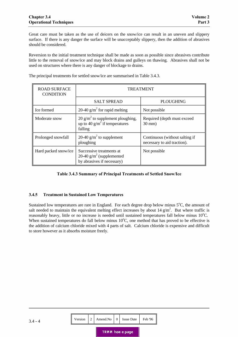
Chapter 3.4 Volume 2Operational Techniques Part 3
Version 2 Amend.No 0 Issue Date Feb '963.4 - 4
Great care must be taken as the use of deicers on the snow/ice can result in an uneven and slipperysurface. If there is any danger the surface will be unacceptably slippery, then the addition of abrasivesshould be considered.
Reversion to the initial treatment technique shall be made as soon as possible since abrasives contributelittle to the removal of snow/ice and may block drains and gulleys on thawing. Abrasives shall not beused on structures where there is any danger of blockage to drains.
The principal treatments for settled snow/ice are summarised in Table 3.4.3.
ROAD SURFACECONDITION
TREATMENT
SALT SPREAD PLOUGHING
Ice formed 20-40 g/m2 for rapid melting Not possible
Moderate snow 20 g/m2 to supplement ploughing,up to 40 g/m2 if temperaturesfalling
Required (depth must exceed30 mm)
Prolonged snowfall 20-40 g/m2 to supplementploughing
Continuous (without salting ifnecessary to aid traction).
Hard packed snow/ice Successive treatments at20-40 g/m2 (supplementedby abrasives if necessary)
Not possible
Table 3.4.3 Summary of Principal Treatments of Settled Snow/Ice
3.4.5 Treatment in Sustained Low Temperatures
Sustained low temperatures are rare in England. For each degree drop below minus 5oC, the amount ofsalt needed to maintain the equivalent melting effect increases by about 14 g/m2. But where traffic isreasonably heavy, little or no increase is needed until sustained temperatures fall below minus 10oC. When sustained temperatures do fall below minus 10oC, one method that has proved to be effective isthe addition of calcium chloride mixed with 4 parts of salt. Calcium chloride is expensive and difficultto store however as it absorbs moisture freely.

Volume 2 Chapter 3.4Part 3 Operational Techniques
Version 2 Amend.No 0 Issue Date Feb '96 3.4 - 5
3.4.6 Spreading Techniques
Purpose built winter maintenance vehicles offer the opportunity to achieve a substantial saving in labourcosts. In particular, the use of powered systems to control spreading eliminates the need for a secondman in the cab during precautionary treatment. The use of a driver and mate shall be restricted tosnowploughing and to other occasions when conditions are hazardous, (eg. when precautionary oremergency treatment is required on particularly isolated stretches of road, when difficult manoeuvres areunavoidable or when visibility is poor). In compounds and depots where hoppers are provided, vehiclescan be loaded by their drivers.
To be effective, salt should be spread evenly and at rates that suit the prevailing or expected conditions. Care should be taken to ensure that spread widths are neither too wide nor too narrow. The treatmentshould be spread by automatic machines, the controls of which shall be calibrated and clearly markedfor distinct rates of spread, up to a maximum of 40 g/m2. Higher spread rates are unnecessary, wasteful,environmentally harmful and shall be avoided.
Cross winds can affect the distance that treatment is spread and to compensate it may be necessary tospread from a lane upwind (if appropriate) from that normally chosen. In exceptionally strong winds itmay be necessary to undertake a second treatment run with the spreader set asymmetrically into thewind.
Due consideration should be given to traffic conditions and the timing of winter maintenance operations.Wherever possible without detriment to the effectiveness of treatment, precautionary salting should beundertaken in off-peak periods when disruption to traffic and to proper distribution of the salt will beminimised. If precautionary treatment in heavy traffic is unavoidable it may be necessary to seek Policeassistance (including motorway matrix signals) or to consider treatment in two runs (to ensure properdistribution of the salt).
Care should be taken at roadworks that in addition to areas currently being trafficked, all other areaslikely to be opened to traffic are treated. Traffic management equipment, including cones and cylinders,may disrupt distribution of salt; contraflow systems should be treated in both directions.
Treatment of any special features such as vehicle arrestor beds should be agreed with the RO andprocedures instigated to ensure compliance with agreed methods of treatment.
3.4.7 Routes
However well vehicle operational routes are planned, a certain amount of wasteful duplication (deadmileage) is inevitable because of network complexities and the siting of compounds and depots. Deadmileage should be kept to a minimum, but first consideration shall always be given to the need toachieve the required treatment time.
At those points on the trunk road network where responsibility passes from one MA to another, bothMAs must liaise closely when defining routes, to ensure that there are no sections of the trunk road, sliproads or service roads that are not covered by either MA.
Operational routes shall be agreed with the Highways Agency's WMRM. Changes to existing or newroutes should be similarly agreed and copies of the new routes shall be provided to the WMRM.
Routes should be reconsidered whenever major roadworks may affect the winter maintenance operation.

Chapter 3.4 Volume 2Operational Techniques Part 3
Version 2 Amend.No 0 Issue Date Feb '963.4 - 6
3.4.8 Snowploughing
It is important to have a clearing policy that is easily understood; the technique used for multi-lanecarriageways should be 'clearance by lane'.
Due to differences in local weather conditions, snow depth, snow wetness and road topography, it isdifficult to be precise on the order of lane clearance. Also, local traffic densities and movements varyfrom day to day and even within a day, and may affect lane clearance priorities.
In prolonged, heavy snowfall the priority will be to maintain a single lane open. In the majority of casesthis will be the more heavily trafficked left hand lane (lane 1) and the first operation will be to ploughsnow from lane 1 to the hard shoulder, with clearance of other lanes continuing as conditions improve.
An alternative technique for a 3 lane carriageway with hardshoulders, particularly suited to echelonploughing (2 or more vehicles moving in the same direction, one behind the other, in different lanes), isclearance in the following sequence:
First : plough lane 2 snow to lane 1;Second : plough lane 1 to hardshoulder;Third : plough lane 3 snow to central reserve;Fourth : plough hardshoulder snow to verge.
More than 2 lanes ploughed onto the central reserve could be hazardous to traffic by inviting driftingand melt water problems later on. When clearing 4 lane carriageways consideration should be given toabandoning lane 4 rather than creating problems of excess snow on the central reserve.
Irregular windrows caused by ploughing passes, especially those that weave from one lane to another,are dangerous, as they may tempt drivers to overtake by squeezing into the partly cleared lane. Lanesshould be completely cleared, and the windrows of snow remaining should form a smooth andcontinuous line without sudden encroachments into the cleared path. On motorways, windrows can beleft on hardshoulders, but there should be intermittent clearings to provide refuge for broken down orabandoned vehicles.
Speeds of ploughing vehicles should be regulated, particularly at features such as underbridges wheresnow could be thrown over the bridge parapet and adjacent the central reserve where snow could bepushed into the opposing carriageway.
The aim is to clear all lanes and hardshoulders as soon as conditions permit. Clearance work shalltherefore proceed continuously, since a pause during a snowfall could lead to a build-up, which wouldtake a disproportionately long time to clear. Packed snow, glazed by the wind, can be particularlydifficult to remove.
Care must be taken to avoid damage to road surfaces, road studs, roadside furniture and structures. Atroadworks, traffic management equipment must not be disrupted. An accumulation of ploughed snowcreating a ramp adjacent safety fences and concrete barriers should be avoided.
When ploughing, motorway warning signals can be displayed, so police co-operation is essential. It isnot always possible to keep these signals free of snow, but every effort should be made to advisemotorists of the snowploughing vehicles ahead.

Volume 2 Chapter 3.4Part 3 Operational Techniques
Version 2 Amend.No 0 Issue Date Feb '96 3.4 - 7
3.4.9 Snowblowing
Heavy snowfall, drifting and ploughing operations may result in a build up of snow in the carriagewayand hardshoulders. Snowblowers are particularly suited to clearance of blockages and to removal ofaccumulations from the hardshoulder and carriageway where snow may be safely directed onto theverge (or possibly a wide central reservation). The Highways Agency's snowblowers, which form partof the reserve fleet, have the capacity to clear up to 2,500 tonnes of snow per hour.
3.4.10 Slip Roads and Interchanges
It is important to maintain the free flow of vehicles at interchanges. At least one lane of each slip roador link road shall be kept open.
At grade separated interchanges, clearance methods should not result in a reduction of the number oflanes on the main carriageway between the exit and entry slip roads, unless this is a feature of thenormal road layout.
Bulk removal of snow from multi-level interchanges (or even some conventional ones) may benecessary on occasions.
3.4.11 Safety of Operatives and Other Road Users
Drivers shall be instructed to take all possible precautions to protect their own safety and that of otherroad users at all times.
Winter maintenance operatives shall wear high visibility clothing incorporating retro-reflectivemarkings at all times when out of a vehicle.
Under the provisions of Section 16(e)(i) of the Motorway Traffic Regulations 1982, the restriction onthe use of central reserve crossovers can be relaxed where it is necessary to maintain or clear part of amotorway. However, in practice, this is a highly dangerous manoeuvre and drivers ofspreading/snowploughing vehicles shall proceed to motorway interchanges rather than use crossovers.The only exceptions are when instructed by the Police or where the crossover is specifically designedfor the purpose, including facility for the vehicle to be clear of the carriageway entirely, and appropriateprocedures for its use have been agreed by the RO.
U-turns on APTRs shall be carried out only when there is no risk to spreading/snowploughing vehicledrivers or to other road users.
Close co-operation is essential between MAs and British Rail. MAs shall ensure that the strictest safetyprecautions are taken when spreading/snowploughing vehicles are negotiating level crossings. Whensnowploughing, care shall be taken that snow does not build up across the tracks or against gates, bridgeparapets, fences and walls.

Chapter 3.4 Volume 2Operational Techniques Part 3
Version 2 Amend.No 0 Issue Date Feb '963.4 - 8
3.4.12 Snow Gates
Procedures for operating snow gates shall be agreed with the RO and the Police.
MAs shall close and subsequently re-open snow gates only upon receipt of instructions from the Police. Should MAs consider that snow is rendering or has rendered the road unsafe to vehicular traffic, theyshall request that the Police initiate procedures to close the snow gates.
3.4.13 Snow Fences
Powers to erect fences, and to ensure easements, are provided in the Highways Act 1980 where Sections102, 249, 251 as modified, 291 and 292 as amended are relevant. Negotiations of terms for thegathering of easements by landowners and tenants shall be undertaken by MAs in consultation with theRO. Cases where agreement cannot be reached shall be referred to the District Valuer.
For guidance in the design and location of Snow Fences, MAs should refer to the Highways Agency'sWMRM.
3.4.14 Porous Asphalt Road Surfaces
Under certain winter conditions porous asphalt requires more attention than comparable conventionalroad surfaces. This is due to different characteristics in respect of surface temperature, road humidityand the ability to retain salt on the surface.
In general, more salt is required for treatment of a porous asphalt road surface than for a dense surfacingmaterial.
At high traffic intensities the behaviour of roads made from porous asphalt barely differs from that ofdense road surfaces. At low traffic intensities however the loss of thawing agent into the voids ofporous asphalt results in greater likelihood of freezing in the event of only a small amount ofprecipitation (condensation, freezing fog) and greater quantities of thawing agent being required to treatheavy precipitation.
Inadequate superelevation or gradient can also be more critical for porous asphalt roads. Precipitation inthe voids of the material may collect and be retained at certain locations. The road surface thus remainsdamp and more likely to freeze in these areas. This action is exacerbated by the differing response ofporous asphalt to temperature change; the temperature of a porous asphalt surface falls below freezingpoint more quickly than a dense road surface and rises above freezing more slowly.
Prompt snowploughing is recommended on porous asphalt road surfaces, but care is required to avoiddamaging the surface. Ploughs shall be fitted with rubber skirts on the blades.
Annex 3.4.1 contains more detailed information on the performance and treatment of porous asphaltin winter conditions.

Volume 2 Chapter 3.4Part 3 Operational Techniques
Version 2 Amend.No 0 Issue Date Feb '96 A3.4.1 - 1
Annex 3.4.1
Treatment of Porous Asphalt Road Surfaces
1. Introduction
Porous asphalt behaves differently from other dense road surfaces, especially in respect of surfacetemperature, humidity and the retention of salt on the surface.
In winter conditions porous asphalt requires closer monitoring, particularly in the following situations:
(a) roads with low traffic flow;
(b) roads on an incline;
(c) roads with a limited superelevation;
(d) hard shoulders;
(e) in the event of changes from cold to warm temperatures;
(f) in the event of snow remaining on the road surface;
(g) in the event of slipperiness caused by condensation;
(h) in the event of slipperiness caused by freezing fog; and
(i) at changeovers from porous asphalt to dense road surfaces.
2. Behaviour of Porous Asphalt with Temperature Change
As temperatures fall, the temperature of road surfaces made of porous asphalt falls below freezing pointan average of half an hour earlier than that of dense road surfaces;
As temperatures rise, the temperature of road surfaces made of porous asphalt rises above freezing pointan average of an hour later than that of dense road surfaces;
The temperature of road surfaces made of porous asphalt remains below freezing point about 5% longerthan that of dense road surfaces;
In extreme weather conditions (little wind, clear sky), the surface temperature of roads made of porousasphalt is about 1oC lower than that of comparable roads made of dense road surfacing materials.
The behaviour of porous asphalt with temperature change can be explained by the relatively highinsulation value of the road surface due to voids. As a result, heat is less easily transported from themostly warm subgrade to the surface in the event of frost from above. The voids also ensure greatercontact surface with the cold air; this greater heat/cold interchange also contributes to the lower

Chapter 3.4 Volume 2Operational Techniques Part 3
Version 2 Amend.No 0 Issue Date Feb '96A3.4.1 - 2
temperature of porous asphalt in comparison with a compact road surface.
In view of the foregoing temperature characteristics, it is recommended that thermal mapping should beperformed on new porous asphalt construction; the thermal mapping survey will assist with the re-sitingof existing ice detection sensors and indicate the most favourable siting of new sensors to provide anaccurate temperature profile of the road. Siting of at least one sensor on all porous asphalt sections isconsidered to be essential.
3. Behaviour of Porous Asphalt with Humidity
The voids in porous asphalt ensure that precipitation is slowly removed to the shoulder as a result of thesuperelevation of the road. Some of the precipitation remains behind in the pores. In summer theremnants quickly evaporate after a wet period, while in winter the road dries slowly. In the case ofroads with a limited superelevation which are on an incline or which have a large number of trafficlanes, moisture remains on part of the porous asphalt for a long time. As a result of this residualmoisture, road surfaces made of this type of asphalt also remain damp.
If the road surface temperature falls below freezing point after a period of precipitation, roads made ofporous asphalt will require extra attention on account of the moisture present.
4. Behaviour of Porous Asphalt with Salt Treatment
Much of the thawing agent spread on roads made of porous asphalt disappears into the voids, and only asmall amount remains on the surface. However, because of the 'air pumping action' effect of vehicletyres, traffic will ensure that the thawing agent in the pores is brought back to the surface of the road. As a result of this vertical transport function performed by traffic, some of the salt which haddisappeared into the voids will continue to contribute to the thawing process. This process will bedisrupted if the traffic intensity is low (eg at night). Even if only a small quantity of moisture falls onthe road at that time (condensation, freezing fog), this can result in non-compact road surfaces behavingdifferently from compact ones. As a result of the extra moisture in the pores of porous asphalt, a largerquantity of salt is required on these roads.
There is another important factor in the effectiveness of winter maintenance treatment, in addition to thedrop in freezing point caused by the application of the thawing agents. On roads made of dense roadsurfacing, traffic readily leads to horizontal transport of the thawing agent (ie in the direction of thetraffic). With porous asphalt this horizontal movement of the thawing agent is considerably less. Asalready mentioned, traffic also performs a vertical transport function on such roads. This means that thesalt spread on porous asphalt roads is mixed with the moisture from the pores. In time a balance arisesin which the salt is distributed as a solution over the pores and the surface as a whole. This solution istransported vertically and to some extent horizontally by the traffic.
Because the moisture in porous asphalt drains away to the shoulder only very slowly, the salt solutionremains available for quite some time. If the vertical balance is disturbed however, less moisture fromoutside will be required to reduce the drop in the freezing point on the surface sufficiently enough toallow the formation of ice than in the case of comparable roads made of dense road surfaces.
Where a stretch of road made of porous asphalt is followed by one made of dense road surfacing, extraattention to the initial section of the dense road surfacing is required. Since the horizontal transport ofsalt on non-compact road surfaces is limited compared to that on compact road surfaces, there is asignificant reduction in the amount of thawing agent in the initial section of dense road surfacing.

Volume 2 Chapter 3.4Part 3 Operational Techniques
Version 2 Amend.No 0 Issue Date Feb '96 A3.4.1 - 3
Traffic and dry conditions ensure that the quantity of thawing agent on a road made of dense roadsurfacing will gradually disappear even without precipitation. On a road made of porous asphalt someof the salt crystallises in the pores under dry conditions. This slow crystallisation ensures good adhesionto the asphalt, and as a result the salt remains available. If salting takes place several times in a dryperiod without the thawing agent being removed to the shoulder - eg if slipperiness occurs as a result offreezing fog or condensation - a salt buffer will be formed in the pores of porous asphalt. If, following adry period, precipitation falls at a road surface temperature below freezing point, the salt buffer whichhas collected in porous asphalt becomes available again under the influence of the traffic.
5. Conclusions
To keep a road made of porous asphalt completely free of snow, more salt is required than for acomparable road made of dense road surfacing.
At high traffic intensities the behaviour of roads made of porous asphalt barely differs from that ofdense road surfaces. At low traffic intensities extra attention is required.
The amount of salt required to keep a road made of porous asphalt passable will be 25% higher than fora dense surfaced road, depending on conditions.
The salt spread on the road ends up on the shoulder. On roads made of porous asphalt this is limited tothe first few metres of the hard shoulder which should result in less environmental damage to trees andplants.
After a salting operation, the skid resistance of a porous asphalt road will decline at low trafficintensities in the event of a small amount of precipitation in the form of glaze ice, freezing fog orsignificant condensation. This can be avoided by prompt salting (sometimes several times).
Inadequate superelevation and inclines allow moisture to collect at certain places on roads made ofporous asphalt. Wet sections of the roads are more likely to freeze in these places, partly as a result ofthe different behaviour of porous asphalt with temperature change.
At low traffic flows with a great deal of precipitation, extra thawing agent is required to make roadsmade of porous asphalt completely free of snow (following snowplough operations).
At high traffic flows and following a heavy snowfall, roads made of porous asphalt are generally morepassable (higher skid resistance) than comparable roads made of dense road surfaces subjected to thesame treatment.

Volume 2 Chapter 3.5Part 3 Use of Winter Maintenance Equipment
Version 2 Amend.No 0 Issue Date Feb '96 3.5 - 1
3.5 Use of Winter Maintenance Equipment
3.5.1 General
The Highways Agency owns the operational and reserve spreading/snowploughing vehicles andsnowblowers used for motorway winter maintenance in England. MAs are notified each year of theoperational vehicles based with them, from which compounds they should operate and on which roadsthey should be used. They are also notified of those compounds where reserve vehicles andsnowblowers are normally kept (see 3.5.3).
MAs or their Contractors normally supply the vehicles and equipment for winter maintenanceoperations on APTRs.
The requirements of this chapter relate mainly to the Highways Agency's vehicles and equipment (butsee 3.5.7).
3.5.2 Operational Vehicles
Except in the circumstances noted below, the Highways Agency's operational vehicles are for routineuse on motorways only. During emergencies, reserve vehicles can be made available, and the procedurefor obtaining them is set out in the Regional "Winter Arrangements" publication.
The motorway treatment routes, that have been agreed with the Highways Agency, sometimes result invehicles travelling on non-motorway roads to minimise `dead mileage'. As long as it does not delay orotherwise adversely affect the treatment of the motorway, treatment of these other roads may take placewithout incurring the vehicle hire charge. This is on the strict understanding that the agreed treatmentroutes are not changed to accommodate the treatment of other roads and that the Highways Agency isonly charged for the treatment of any trunk roads.
Very occasionally, the Highways Agency will agree to the use of one of its vehicles on non-motorwayroads on a routine basis, for example on major APTRs linking motorways. The operational andfinancial arrangements for use of these vehicles will be formally agreed with the RO.
Operators should note that the "overall width" of a vehicle, as defined in the Road Vehicles (Construction and Use) Regulations 1986, excludes "any snowplough fixed in front of the vehicle". Where width restrictions are imposed by a Traffic Regulation Order however the particular definitionfor the purpose of that Order should be determined.
3.5.3 Reserve Vehicles
Reserve vehicles are strategically placed in compounds along the motorway network for rapiddeployment. They are not allocated to a particular MA, and cannot be used without prior approval,which must be sought from the WMRM or WMAM (see chapter 3.2).
Reserve vehicles may only be used for the following purposes:
(a) on the motorway when operational vehicles have broken down; have been withdrawnfrom service for other reasons agreed by the WMAM; or when the operational vehiclesalone cannot cope because of severe conditions.

Chapter 3.5 Volume 2Use of Winter Maintenance Equipment Part 3
Version 2 Amend.No 0 Issue Date Feb '963.5 - 2
(b) off the motorway when MA's vehicles alone cannot cope because of very severeconditions. (Reserve vehicles used off the trunk road network are subject to hirecharges).
If a reserve vehicle is used for any reason, the conditions of hire must be strictly adhered to. The hirecharges will be raised for the total length of time the vehicle is away from its allocated compound; sovehicles should be returned promptly.
3.5.4 Garaging of Vehicles and Availability for Inspection
The Highways Agency's winter maintenance vehicles, including snowploughs and related equipment,shall be kept properly garaged at the allocated compound unless other arrangements have been made bythe Highways Agency. They must also be available for inspection by the WMAM at all reasonabletimes without prior notice.
3.5.5 Large Goods Vehicle Driver Licence Requirements
Spreading/snowploughing vehicles are classified as Class C, Large Goods Vehicle (LGV). Snowblowers are classified as Class B vehicles. Drivers shall hold a valid UK licence, or equivalentrecognised licence issued by a state of the European Economic Area, for the relevant class of vehicle.
3.5.6 Use of Vehicles for Driver Training
Where a MA has no Class C LGV vehicles of its own, it may apply to utilise one of the HighwaysAgency's vehicles during April to October, as long as training is only for drivers expected to operate thevehicles. Applications shall be made in writing annually to the Regional Office, and should show theregistration number of the vehicle requested. Full vehicle insurance cover shall be provided by the user.
3.5.7 Operator Training, Assessment and Registration
Winter maintenance vehicles shall only be operated by trained staff. MAs shall ensure that all wintermaintenance operators and drivers on motorways and all purpose trunk roads are trained and assessed tomeet the requirements of the Winter Maintenance Operators Qualification - awarded by the City andGuilds Institute (Scheme 6157) or equivalent recognised qualification awarded by a state of theEuropean Economic Area; qualified operators and drivers shall be registered with the Local GovernmentManagement Board.
The 6157 qualification comprises units on operation of prime mover, operation of spreader andoperation of snowplough - covering both Highways Agency and non-Highways Agency vehicles. Forthose drivers/operators on all purpose trunk roads, the units dealing with the prime mover and spreadercan be assessed on the available level of vehicles and equipment, recognition as a registered HighwaysAgency operator on all purpose trunk roads will not be dependent on gaining units which refer only tothe Highways Agency's vehicles. For maximum flexibility in severe weather conditions, however, itcould be advantageous for all operatives to be able to use the Highways Agency's vehicles.

Volume 2 Chapter 3.5Part 3 Use of Winter Maintenance Equipment
Version 2 Amend.No 0 Issue Date Feb '96 3.5 - 3
3.5.8 Vehicle Insurance
The Highways Agency's vehicles are deemed to be on Crown duty whilst operating on trunk roads andwhen:
(a) travelling to and from such roads for operational use;(b) making servicing journeys;(c) on standby at their authorised station.(d) used for Winter Maintenance Operators qualification training/assessment.
Whilst on Crown duty they are exempt from the compulsory insurance requirements of Section 143 ofthe Road Traffic Act 1988 and 1991 by virtue of Section 183(1) as amended of that Act, and the Crownaccepts liability for third party claims or damage to the vehicles.
The vehicles are not considered to be on Crown duty when operating on non-trunk roads, or when beingused for LGV driver training. The hirer must be covered to meet all costs arising from any damage tothe vehicles caused by an accident, and must ensure that he has sufficient cover to meet claims forwhich he may be liable.
3.5.9 Reporting of Vehicle Accidents
MAs shall report to the WMAM all accidents, however minor, involving vehicles. A fatal or seriousinjury accident shall be reported immediately by telephone.
A form DTp 20001, which is kept in the cab, shall be completed as soon as possible after the accident. The form shall, so far as possible, be completed at the scene of the accident. The driver shall also makeout a written statement of the circumstances of the accident and sign it. The form, together with thedriver's signed statement and any statements that have been made by witnesses, shall be forwardedimmediately to the WMAM.
MAs shall ensure that drivers are familiar with the instructions for completion of form DTp 20001, andthat all relevant information, including an estimate of the vehicle repairs, is given.
3.5.10 Grade of Fuel
To minimise the risk of immobilisation due to diesel engine fuel waxing at low temperatures, it isessential for vehicles to be fuelled with a suitable grade of fuel at winter's onset. In order to furtherreduce the risk of fuel waxing, vehicles should not be left standing in the open for longer than necessary.
3.5.11 Use of Rebated Fuel
Rebated fuel oil shall be used whenever possible, as its use is allowed in vehicles entitled to exemptionfrom excise duty under Section 4(1)(i) or Section 7(3) of the Vehicles (Excise) Act 1971. Furtherdetails are given in the "Winter Arrangements" publication. Full licensed goods vehicles employed onwinter maintenance work must use unrebated fuel at all times.

Chapter 3.5 Volume 2Use of Winter Maintenance Equipment Part 3
Version 2 Amend.No 0 Issue Date Feb '963.5 - 4
3.5.12 Safety Precautions in Non-Operational Use
When winter maintenance vehicles are used on the highway for training or maintenance runs, thespinner disc at the rear of the vehicle shall be covered in such a way that damage by sharp edges, in theevent of an accident, is reduced to a minimum.
3.5.13 Servicing of Winter Maintenance Vehicles
a) General
Throughout the year MAs are required to carry out routine maintenance of "WinterMaintenance" vehicles and equipments allocated to them. This is to include those vehicles andequipments nominated as national reserve and other vehicles on temporary loan.
To minimise the adverse effects of operating winter maintenance equipments within a salt ladenenvironment it is essential that the instructions contained within the maintenance schedules arestrictly adhered to.
b) Routine Maintenance
Routine maintenance is confined to "User Maintenance and Servicing" as defined and detailedin the equipment's Maintenance Schedule (WM-GF2-611). A copy of the schedule along withthe Operator Information is provided in the vehicle cab.
The designated operator is responsible for ensuring that "User Maintenance and Servicing" iscarried out in accordance with the Driver/Operators Checks. MA's are authorised to carry outthe defined routine maintenance without reference to WMAM's.
The WMAM is responsible for monitoring the operator's compliance with the schedule.
A Vehicle Service Record (WM31) is to be kept in each vehicle. Service records for all WinterMaintenance Vehicles/Equipments are to be maintained by the operator including those ontemporary loan.
c) Periodic Maintenance
Periodic Maintenance and Inspection of equipment is not part of Routine Maintenance and mayonly be carried out when specifically authorised by the WMAM.
Periodic Maintenance and Inspection of equipment is defined and detailed within theEquipment's Maintenance Schedule (WM-GF2-611). Copies of the Schedule and OperatorInformation are provided within the vehicle cab.
The WMAM is responsible for the proper application of Periodic Maintenance.

Volume 2 Chapter 3.5Part 3 Use of Winter Maintenance Equipment
Version 2 Amend.No 0 Issue Date Feb '96 3.5 - 5
3.5.14 Salt Loading Hoppers
The Highways Agency provides salt loading hoppers at some motorway compounds. MAs may beresponsible for the routine maintenance of the salt loading hoppers as instructed in WM31H. WMAMsare available to visit and advise on care and maintenance of hoppers.
During April, or at the end of winter use, MAs shall empty and clear away all salt from the loadingequipment and adjacent areas. The equipment shall be washed down thoroughly, to avoid the saltsolidifying in the equipment, and lubricated before a detailed examination and annual service isarranged by the WMAM.
3.5.15 Other Plant and Equipment
MAs are responsible for the maintenance and repair of all motorway compound plant and equipment,except where other arrangements are specified by the Highways Agency.
3.5.16 Emergency Power Supplies
MAs should prepare contingency plans to cope with power or communication cuts other than those of avery temporary nature. All the Highways Agency's compounds are wired to accept the installation ofgenerators. The Highways Agency provides emergency standby generators at key depots during thewinter maintenance season. Temporary hire of additional generators shall be agreed with the RO.

Volume 2 Chapter 3.6Part 3 Compounds and Depots
Version 2 Amend.No 0 Issue Date Feb '96 3.6 - 1
3.6 Compounds and Depots
3.6.1 General
The Highways Agency provides a number of motorway maintenance compounds throughout England,and shares MA's depots in a few cases where this is more convenient for both parties.
3.6.2 Health and Safety
The Highways Agency's requirements for management of health and safety within trunk roadcompounds are detailed in Volume 3 of the Trunk Road Maintenance Manual.
MAs are responsible for co-ordinating health and safety within compounds on a day-to-day basis and forensuring compliance with agreed policies, standards and procedures applicable to the compound. TheMA shall report to the WMAM responsible for the compounds.
Compounds used for trunk road maintenance but not owned by the Highways Agency should adoptsimilar policies, standards and procedures thus engendering a uniform approach to health and safety incompounds.
3.6.3 Compound Design
Guidance on the design of motorway maintenance compounds and the facilities to be provided is givenin the Highways Agency's Design Manual for Roads and Bridges (DMRB) Volume 2, Section 2;BD4/96 "Design Brief for Motorway Maintenance Compounds".
Volume 2 Chapter 3.7Part 3 Salt
Version 2 Amend.No 0 Issue Date Feb '96 3.7 - 1
3.7 Salt
3.7.1 General
Salt to be used for the winter maintenance treatment of trunk roads shall be a suitable grade so as to befit for the purpose. Periodic sample checks and tests shall be carried out, as appropriate, to ensurecontinued suitability.
Generally, salt is also treated with an anti-caking agent, such as sodium ferrocyanide. Salt which has notbeen treated may solidify, leading to storage, loading and spreading difficulties. The density of saltranges from about 1.2 to 1.5 Tonne/m3 according to origin and moisture content. Salt shall be kept asdry as possible to lessen the problems of caking, especially when loading and discharging from hoppersand vehicles.
3.7.2 Properties
Salt (sodium chloride NaCl) will melt ice and snow at temperatures as low as minus 21°C, but belowminus 10°C the amount needed increases significantly so that it becomes environmentally andeconomically undesirable. For trunk roads, salt shall be used down to about minus 10°C. Whentemperatures fall below minus 10°C, it may be necessary for additives to be mixed with the salt(see 3.4.4 and 3.4.5).
3.7.3 Storage
Salt shall be kept as dry as possible by proper storage. Wet salt tends to attack spreading equipmentmore than dry salt and so increases maintenance costs. Dry salt can be spread more accurately andeconomically on the road.
Salt shall therefore be covered. An uncovered salt pile will form crusts on the surface, and wet salt, ifsubjected to prolonged low temperatures, may solidify (because of the formation of sodium chlorideanhydrate), creating a risk of contamination through rainfall run-off.
Bases for salt storage shall not be made of earth, rubble, clinker, spent tarmac or other loose material asthis can become mixed with the salt and cause obstruction and damage to spreading and loadingvehicles. A hard, smooth, durable surface which is resistant to salt-induced spalling is recommended. Salt piles shall not be stored within the rooting area of trees or within 4.5 metres of hedges. Salt storedwithin 15 metres of tree rooting areas shall be on impermeable foundations.
Drainage of salt storage sites requires particular attention. Ideally, the salt base should be encircled bya cut-off drain. Run-off from other parts of the site shall not underwash the pile. It is important that thewater content of a stockpile is not increased by ground water rising into it. The centre of the pile shallbe higher than its perimeter so that any drainage moisture will flow to the outer edges and away. Thesurface of piles shall be convex and limited in height to avoid the creation of steep faces liable to suddencollapse. Where there are two or more piles closely situated, provision shall be made for adequatedrainage between them.
Salt barns have clear advantages over salt stacked in the open, since no salt is lost to rainfall (largeuncovered piles typically lose approximately 0.13% to 0.25% per year of the initial weight of salt foreach inch of rainfall). Salt in barns stays dry, and drainage and pollution problems are reduced to aminimum. The cost of the barns can be kept down by careful design and the use of proprietary building

Chapter 3.7 Volume 2Salt Part 3
Version 2 Amend.No 0 Issue Date Feb '963.7 - 2
systems. Guidance on the design of salt barns is given in the Highways Agency's Design Manual forRoads and Bridges (DMRB) Volume 2, Section 2; BD4/96.
Protective sheeting shall be used to cover salt not stored in barns. Sheeting should be placed over thepile in manageable sections and all joints over-lapped by about 2 metres. Sheeting should be arrangedto encourage salt being taken from one end only, in order to limit moisture absorption. Ideally, theexposed end should be re-covered after each salt take. Sheeting should be held down by being coveredwith a suitable net. Weights, such as old tyres or railway sleepers should be placed on the top andaround the base, leaving adequate drainage paths. Netting should be uniformally tense, keeping thesheets tightly in place even if the pile settles. A wall around the pile makes it easier to hang weights onthe netting.
Salt hoppers make loading the spreading/snowploughing vehicles quick and easy, even whenconditions are poor. They should be used to full advantage when provided.
3.7.4 Environmental Aspects
Salt accelerates the corrosion of metal when it is exposed to the air and especially when the moisturelevel is high. The corrosion of steel in reinforced concrete is particularly insidious as it spalls theconcrete and eventually leads to its disintegration. Protection is often provided by impregnationtreatments to exposed concrete and applying waterproofing membranes to bridge decks.
The corrosive nature of salt makes careful cleaning and maintenance of the vehicles and plant essential. They shall be regularly washed down and lubricated (see chapter 3.5).
A strong solution of salt in ground water can affect the properties of soils, resulting in the dehydration ofplants, but, provided that the rate of spread is not greater than specified in chapter 3.4, the resulting saltsolution will not be strong enough to unduly affect roadside vegetation, nor is run-off from thecarriageway likely to threaten aquatic life or drinking water supplies.
Run-off from large salt stockpiles may however give cause for concern about pollution of watercoursesand groundwaters. This can come from both the salt itself and the sodium ferrocyanide anti-cakingagent which is often added to it.
3.7.5 Salt Stocks
An efficient service depends on the adequate stockpiling of salt before the winter starts and a closewatch being kept on stocks to ensure that replenishment takes place, if need be, well before the salt runsout.
Unless other arrangements prevail, stocks of salt shall be ordered, and paid for, by MAs (or theirContractors as appropriate) in the first instance and quantities used on the trunk roads shall be chargedto the Highways Agency. Some suppliers of rock salt offer price reductions if firm orders are placed atcertain times of the year. Suppliers should be asked about such arrangements and full advantage shouldbe taken of them, where possible.

Volume 2 Chapter 3.8Part 3 Alternative De-Icers
Version 2 Amend.No 0 Issue Date Feb '96 3.8 - 1
3.8 Alternative De-Icers
3.8.1 General
This chapter gives general information on the principal types of commercially available de-icingmaterials which might be considered as an alternative to rock salt.
Alternative de-icers are usually more expensive and their use is subject to approval by the HighwaysAgency. Full and detailed substantiation of the benefits derived from use of the chosen de-icer inpreference to rock salt will be required. It is anticipated that any use of an alternative de-icer will berestricted to isolated, very specific circumstances.
Alternative de-icing materials which might be considered include:
(a) urea(b) acetate salts(c) acetate salts in solution(d) glycol(e) brine and pre-wetted salt
3.8.2 Urea
(a) General
Urea is a white, crystalline substance with a bulk density of approximately 0.74 Tonne/m3. It isnormally supplied as spherical pellets and applied using a purpose built spreading vehicle, withwetting of the compound taking place immediately prior to its release onto the spinner of thespreading vehicle.
(b) Properties
The recommended spread rates for urea vary from 20 g/m2 for a normal precautionary treatmentto 50 g/m2 in severe conditions. The de-icing action is not immediate and agitation by traffic isnecessary for effective reaction.
The de-icing properties of urea depend on the temperature and on the proportion of urea presentin the water (i.e. ice or snow). For example, a solution of 10% urea to water by weight preventsicing down to about minus 3oC; a 25% solution prevents icing to about minus 7oC. Below thistemperature urea has little worthwhile effect and ceases to melt ice altogether at minus 11.5oC.
Urea remains effective for up to 12 hours in fair weather but repeat applications need to be morefrequent in rain or strong winds.
Urea is spread in conjunction with a wetting agent (a mixture of water and anti-freeze) toimprove spreading uniformity, increase adhesion to the road and resist the material being blownaway. It increases the skid resistance of an icy road, but not as dramatically as salt, and thewetting agent can initially have an adverse effect on skid resistance.

Chapter 3.8 Volume 2Alternative De-Icers Part 3
Version 2 Amend.No 0 Issue Date Feb '963.8 - 2
(c) Storage
Urea should be stored, loosely or in 50 kg bags, in a dry, cool building, giving protection fromthe weather and free from appreciable temperature fluctuations so that condensation from theatmosphere is avoided. Bags, if used, should preferably not be stacked directly upon concretefloors and pallets should not be stacked more than two high as pressure tends to promotecracking and setting. The building should be well ventilated, to prevent the build up ofammonia fumes, particularly in summer. Forced ventilation may be necessary if all doors andwindows are closed. Bulk urea can also be stored in purpose built, plastic lined timber hoppers.
When heated at or above its melting point, urea decomposes with the formation of biuret,cyanuric acid, ammelide and other related products. Therefore, no attempt to deal withsubstantial fires in urea storage areas should be made by anyone other than trained fire-fighters,properly equipped with breathing apparatus. Local Fire Fighting Services should be informedof urea stock sites.
Urea is safe to handle but the pellets break into powder easily; face masks and eye protectionare recommended. It also becomes very slippery when spilt due to its high hygroscopic nature.
(d) Environmental Aspects
Urea is non-aggressive, but very soluble in water, and its aqueous solution may be hydrolysed toproduce ammonia and carbon dioxide.
Ammonia is toxic to aquatic life. In addition ammonia further decomposes to nitrate which, aswell as promoting growth of vegetation, creates an oxygen demand that may cause further harmto life.
Urea in solution is known to have been deleterious to steel, plastics and concrete in somecircumstances. Vehicles should not be left full of urea for any length of time; particularproblems with urea solidifying have occurred because of loads being left in the vehicles. Vehicles should be thoroughly washed down after use.
3.8.3 Acetate Salts
(a) General
Commercially available de-icing materials based on acetate salts are supplied as small granulesor pellets, have a bulk density of approximately 0.75 Tonne/m3 and are applied either dry orwith pre-wetting immediately prior to release onto the spinner of the spreading vehicle.
(b) Properties
Recommended spread rates for acetate salts vary from 20 g/m2 to 40 g/m2 depending onconditions. The de-icing action is not immediate and agitation by traffic is necessary foreffective action.

Volume 2 Chapter 3.8Part 3 Alternative De-Icers
Version 2 Amend.No 0 Issue Date Feb '96 3.8 - 3
The effectiveness of acetate salts decreases below minus 5oC and they are largely ineffectivebelow minus 15oC. The residual effect of these materials is greater than for rock salt.
Acetate salts are usually applied dry from a conventional spreading machine although pre-wetting with an acetate salt in solution can improve the effectiveness of spreading, increaseadhesion to the pavement surface and instigate immediate melting.
(c) Storage
Acetate salts are usually supplied in 600-1000 kg polythene lined bags which can be stored in adry warehouse and handled by fork lift truck. Alternatively, bulk storage is possible in plastic-lined timber hoppers.
Gloves, eye protection and dust masks are recommended when handling acetate salts, althoughthey do not constitute significant health hazards.
(d) Environmental Aspects
Acetate salts are significantly less corrosive than rock salt, have little effect on constructionmaterials generally and are safe to aquatic life.
3.8.4 Acetate Salts in Solution
(a) General
De-icing materials based on acetate salts in solution have a density of approximately1.25 Tonne/m3 and are sprayed directly onto the road surface.
(b) Properties
Recommended spread rates for these liquids vary from 10 g/m2 for precautionary treatment upto 40 g/m2 for de-icing. The solution acts almost instantaneously.
Acetate salts in solution may remain effective for up to 48 hours in suitable weather conditions. They are effective down to a minimum temperature of minus 15oC and have been shown tomelt ice faster than rock salt and most alternatives.
Application of acetate salts in solution may be either by spray bar or via a spinner. The skidresistance of a wet road is not significantly affected by a precautionary treatment.
(c) Storage
Acetate salt solutions can be stored in bulk in steel tanks or supplied and stored in 210 litredrums.
Gloves and eye protection are recommended, although the solutions are safe to handle.
(d) Environmental Aspects
Acetate salts in solution are significantly less corrosive than rock salt, have little effect onconstruction materials generally and are safe to aquatic life.
Chapter 3.8 Volume 2Alternative De-Icers Part 3
Version 2 Amend.No 0 Issue Date Feb '963.8 - 4
3.8.5 Glycol
(a) General
Glycol-based water-soluble de-icing fluids have a density of approximately 1.25 Tonne/m3 andare sprayed directly onto the road surface.
(b) Properties
Recommended spread rates for glycol-based de-icers vary from 10 g/m2 for precautionarytreatment to 40 g/m2 for de-icing.
Glycol-based de-icers are effective down to minus 12oC and remain effective for up to 24 hoursin light traffic and suitable weather conditions.
Application of glycol-based de-icing fluids may be either by spray bar or via a spinner. Theskid resistance of the road surface is temporarily reduced immediately after application, but noadverse effect is apparent after approximately 10 minutes.
(c) Storage
Glycol-based solutions may be stored in bulk in steel tanks or in 210 litre drums.
Gloves and eye protection are recommended. Glycol based solutions are harmful if swallowed.
(d) Environmental Aspects
Glycol-based solutions have no noticeable effect on construction materials but in highconcentrations they can be toxic to aquatic life.
3.8.6 Brine and Pre-wetted Salt
(a) General
A 25% reduction in rock salt usage can be achieved by pre-wetting the salt with water, or a75% reduction can be achieved by producing brine; a fully saturated solution of salt in water.
(b) Properties
Pre-wetted salt and brine are effective over a similar temperature range to rock salt but adhereto the road better than dry salt and can be spread more uniformly with less wastage. A fasterapplication rate is possible and the de-icing action is more immediate. Brine is more easilydispersed by rain.
(c) Storage
Pre-wetted salt is stored as dry salt; the water being added immediately prior to application. Brine may also be stored primarily as dry salt, with a batching plant in the compoundproducing the brine which would then be held in an appropriate tank.

Volume 2 Chapter 3.9Part 3 Thermal Mapping
Version 2 Amend.No 0 Issue Date Feb '96 3.9 - 1
3.9 Thermal Mapping
3.9.1 General
Thermal mapping of a road network identifies temperature profiles and particular problem areas,different climatic zones, and ice prediction sensor sites. A thermal map can be used to extrapolateinformation from specific sensors to the whole network.
The Highways Agency, in consultation with FOs and companies which carry out thermal surveys, hasdrawn up a specification for thermal mapping (see Annex 3.9.1). If a MA wishes to establish predictivethermal map facilities within its ice prediction system, then thermal maps produced from severalsurveys, made under different but representative weather conditions, need to be stored in digital form inthe system's database.
Surveying is carried out using equipment mounted in either an aeroplane or road vehicle. As aerialsurveying techniques are restricted to operating in clear conditions, they cannot provide a completerange of thermal maps for predictive displays. However, they are suitable for sensor location andhave the benefit of surveying large geographical areas quickly. They also have the advantage overground based surveying techniques of providing detailed information of roadside features that affectroad surface temperatures, as well as surveying all lanes of multi-carriageway roads.
Volume 2 Chapter 3.9Part 3 Thermal Mapping
Version 2 Amend.No 0 Issue Date Feb '96 A3.9.1 - 1
Annex 3.9.1
Thermal Mapping Specification(Ref. no. : HM-TM1, 1988)
Contents
Section
1. Introduction
2. Definitions
3. Applications of Thermal Maps
4. Specification
4.1 Thermal Surveys4.2 Route Surveys4.3 Weather Conditions for Thermal Surveys4.4 Results in Digital Form4.5 Tabular Data4.6 Results in Pictorial Form4.7 Explanatory Text4.8 General Notes on the Results
5. Factors Controlling Road Surface Temperature
5.1 General5.2 Temporal (diurnal) Variations in Road Surface Temperature5.3 Altitude and Topography5.4 Sky-view5.5 Road Construction5.6 Urban Heat Islands5.7 Traffic5.8 Weather

Volume 2 Chapter 3.9Part 3 Thermal Mapping
Version 2 Amend.No 0 Issue Date Feb '96 A3.9.1 - 5
1. Introduction
The Highways Agency encourages MAs to install ice prediction systems as an aid to improve forecastsof road conditions, leading to a more cost effective winter maintenance service. Specification numberTR2020 describes how such systems operate in the interests of a National Ice Prediction Network (seeAnnex 3.10.1).
This Specification details the parameters to which companies offering thermal mapping services mustoperate, the weather conditions under which they must be carried out, and the format in which theresults must be presented to MAs if the Highways Agency is to recompense MAs for thermal mappingof the trunk roads. MAs should ensure that firms appointed to carry out thermal mapping do so inaccordance with this Specification.
2. Definitions
Minimum Road Surface Temperature: The lowest temperature reached by the road surface at agiven point during the night. (The minimum road surface temperature normally occurs at about the timeof sunrise).
Route Survey: The observation and recording of all spatial and other factors on an adjacentcarriageway that can significantly affect minimum road surface temperature. (eg. road construction,emissivity, orientation, slope, embankments, cuttings, trees, etc).
Thermal Survey: The measurement and recording of spatial variations of road surface temperatureusing passive infra-red sensors.
Thermal Map: The representation on a road map (typically at a scale of approximately 1:50,000) ofthe spatial variations of minimum night-time road surface temperature.
Thermal Mapping: The process of producing a thermal map. This includes the measurement of roadsurface temperatures, the application of any corrections required to calculate road surface temperaturesat a particular reference time and the presentation of the results.
Reference Time: A single time to which observations from a thermal survey are corrected, soeliminating the influence of temporal changes in road surface temperature when surveys take asignificant length of time.
3. Applications of Thermal Maps
Road surface temperature varies in both space and time. It is dependent on certain fixed factors such asaltitude, topography, road construction and sky-view factor and on variable factors such as trafficdensity and weather conditions. For the way these factors control road surface temperature see Section5 of this Annex. Thermal maps, which depict the spatial variations in minimum road surfacetemperature, have several applications which include either:
(a) identification of those points on the road at which road surface sensors should be installed toprovide the most complete and representative information on road surface conditions possiblewith a small number of sensors; or

Chapter 3.9 Volume 2Thermal Mapping Part 3
Version 2 Amend.No 0 Issue Date Feb '96A3.9.1 - 4
(b) indication, for particular weather conditions, of how the minimum road surface temperatures atall mapped points on the road network are related to the minimum road surface temperature atthose points where measurements and/or forecasts are available.
4. Specification
4.1 Thermal Surveys
(a) Thermal surveys must be carried out between midnight and sunrise during the monthsNovember to March. Outside these periods ie. between sunrise and midnight during the wintermonths and at any time between April and October variations in roads surface temperaturedepend more on traffic density and the receipt of solar radiation during the day, than on the lossof terrestrial radiation at night. However in Scotland, it might be possible to continue surveyingto mid-April.
(b) Each survey shall be labelled with the date and time.
(c) The resolution of recorded road surface temperature data shall be 0.2°C (or better) and theaccuracy shall be 1.0°C as demonstrated in calibration checks. This accuracy must bemaintained over the full operational range of the equipment used for the thermal survey.
(d) The average road surface temperature for a given run shall not be greater than plus 5°C.
(e) Measurements of road surface temperature must be made at least every 20 metres along theroad, although it may be necessary to take closer readings (every 5 metres, say) in areas wheresensor locations are being identified. Actual siting of sensors will be restricted by theavailability of power and telephone services. Where possible sites should be chosen so thatvandalism of roadside equipment is unlikely.
(f) The value of emissivity of the road surface used to derive each road surface temperature shallbe recorded.
(g) The state of the road surface at the time of the thermal survey shall be recorded (ie. dry, wet,frost, ice or salt).
(h) For each thermal survey a detailed description of the prevailing weather conditions shall beprovided. This shall include:
i) cloud type, amount and cloud base height (low, medium or high). This informationmay be obtained from the local FO;
ii) wind speed and direction. Actual height at which the wind is measured to be stated. Measurements to be corrected to a height of 2 metres using Table 3.9.1;
iii) air temperature (at a height of 1.25 m);
iv) dew point temperature (at a height 1.25 m).

Volume 2 Chapter 3.9Part 3 Thermal Mapping
Version 2 Amend.No 0 Issue Date Feb '96 A3.9.1 - 5
Height ofwind observation (m)
Multiplying factor to be used to obtain wind at2 m height
cloudy and/or windy clear, very light winds
135
1.20.90.5
1.30.90.5
Table 3.9.1 Wind Speed Correction Factors
The above measurements must be made at a point representative of the area of the survey and atthe start and end of the survey. The local FO may be asked to provide supplementary weatherdetails from the nearest weather station. Conditions shall be recorded at least hourly. Thedescription shall also include text describing changes in weather conditions along the routewhich are not adequately defined by the above information.
(i) When ground based thermal surveying techniques are used, surveys of both sides of a dualcarriageway are not normally necessary but should be done if the two carriageways divergesignificantly or differ in construction, as in the case of an 'old' road forming one carriageway ofa dual carriageway. Where there is more than one lane, data is ideally required for therighthand lane which is normally colder. However, as no vehicle should run continuously in therighthand lane, measurements should be taken in the centre lane of a 3 lane carriageway or thelefthand lane of a 2 lane carriageway. Sample runs in the righthand lane should be made toestablish the relationship. The police should be informed if surveying is likely to causeproblems for traffic. Aerial surveys automatically include both carriageways plus hardshoulders, verges and adjoining land.
(j) Survey times should not be greater than one hour, preferably less. However, if a thermal surveylasts more than 1 hour it is essential to survey parts of the route(s) twice to quantify changes inthe road surface temperature with time, to enable all temperatures to be adjusted to a commonreference time, preferably around the time of minimum road surface temperature.
4.2 Route Surveys
The route survey shall provide the following information:
(a) Reference to the MA's CHART referencing system and to other major features such as bridgesand main interchanges;
(b) Changes in road surface type with reference points (eg. black top, concrete or elevated);
(c) Presence or absence of trees, hedges, buildings, cuttings and embankments (if they dominate orhave influence upon the road surface temperature).
Note: All the above should be identified within the MA's CHART referencing system.

Chapter 3.9 Volume 2Thermal Mapping Part 3
Version 2 Amend.No 0 Issue Date Feb '96A3.9.1 - 6
4.3 Weather Conditions for Thermal Surveys
Thermal surveys may be required in any of the following conditions:
(a) Calm and clear: wind speed less than 6 knots at 2 metres height, with negligible amounts of lowand medium cloud;
(b) Windy and cloudy: wind speed more than 6 knots at 2 metres height, thick low cloud;
(c) Intermediate conditions: surveys here will require individual analysis but can be helpful to showthe sort of variations which occur between the two extremes covered by (a) and (b). Particularcare is required for non-uniform cloud situations as the cloud will be a significant factor. Preference should be given to windy and clear conditions or to calm and cloudy conditions, ifpossible.
The number of thermal surveys required and the weather conditions in which they should be carried outdepends on the use to be made of the resultant thermal maps. If the thermal map is to be used only forsensor site selection, a single thermal survey made in calm and clear conditions may suffice, but this is aminimum requirement. One single run, even under clear calm conditions, will not necessarily give arepresentative thermal map, although one airborne survey will provide rapid synoptic imaging with highspatial resolution along an entire route corridor.
If a thermal map is required as an aid to the prediction of road surface temperature and the managementof winter maintenance, a series of thermal surveys (usually 5) must be made under different weatherconditions. MAs should consult their local FO to advise on how many runs are required. (eg. Extrasurveys may be required for different wind directions where there are important local influences likeconurbations or coasts and hills).
4.4 Results in Digital Form
For each survey, the results of all runs carried out are required in digital form as specified in Table 3.9.2.The following information shall be given at maximum intervals of 20 metres:
(a) Position along road (in metres from CHART nodes);
(b) Emissivity used to correct observations to road surface temperature, to 0.5%;
(c) Temperature (°C), recorded with a resolution of 0.2°C;
(d) Corrected temperature (°C), also to 0.2°C, at a common reference time, after correction toaccount for the duration of the survey;
(e) Two further temperatures, (as required, referring to righthand lane as (a) to (d)).
This data shall be preceded by a file giving date, time and position (relative to MA's reference points) atthe start and end of the survey. When a survey involves an out and back, or circuitous traverse, thisinformation shall also be given for the turning points of the traverse. The file shall also include thesurvey reference point, the reference time to which the temperature measurements are corrected, andwhether temperature data are given for both righthand and lefthand lanes of the road (righthand andmiddle lanes for a 3 lane carriageway). The file will also have a detailed description of the prevailingweather conditions at the start and end of the survey, and (for long surveys) at intermediate hours too.

Volume 2 Chapter 3.9Part 3 Thermal Mapping
Version 2 Amend.No 0 Issue Date Feb '96 A3.9.1 - 7
Item No Description Character format
1 Route description, including location references at start and end ofsurvey, and at intermediate points on the route.Place of measurement of air temperature, wind speed, cloud.
up to 1024 ch. in length
2 Survey date (DDMMYY) I6
3 Start time (GMT) (HHMM) I4
4 End time of survey (GMT) (HHMM) I4
5 Height of dry bulb and dew point measurements (m) F4.2
6 Height of wind speed measurement (m) F5.1
7 Start air temperature (°C) F5.1
8 Start dew point temperature (°C) F5.1
9 Start cloud cover (0-8), cloud type+ and cloud base height (ft) 3(I1, Char, I5)
10 Start wind speed (knots), as measured, and corrected to 2 m height,and direction
2 I2 Char*3
11 End air temperature, dew point, cloud, wind speeds and direction 2F5.1, 3(I1, Char, I5), 2I2, Char*3
12 Number of intermediate (hourly) meteorological observations I1
13 Start time of intermediate meteorological observations (HHMM) I4
14-37 Hourly intermediate observations as 7-10 above 2F5.1, 3(I1, Char, I5), 2I2, Char*3
38 Reference point (8 figure National Grid Reference (NGR)) from whichsurvey distances are measured
I8
39 Reference time to which survey temperatures are corrected (HHMM) I4
40 Indicator for lane carriageway.1. middle/lefthand lane only;2. righthand and middle/lefthand lane surveyed
I1
41-?? Time (HHMM, every kilometre);Distance (in m);Emissivity used to correct observations to RST (%);Road temperature (°C) to 0.2°C;Estimated temperature at reference time after correction to allow forsurvey duration;2 optional further temperatures if righthand lane data are also available
(I4,I6,5F5.1)
Note: + L = low cloud (base <8000 ft);M = medium cloud (base 8000-20000 ft);H = high cloud (base > 20000 ft)
Table 3.9.2 Format of Digital Data

Chapter 3.9 Volume 2Thermal Mapping Part 3
Version 2 Amend.No 0 Issue Date Feb '96A3.9.1 - 8
4.5 Tabular Data
The data from the route survey shall be given as specified in Section 4.2. For each survey, a detaileddescription of the prevailing weather conditions is required, as specified in Section 4.1 (h).
4.6 Results in Pictorial Form
The digital data, corrected to the survey reference time, shall be used to show the variation oftemperature along the survey route in graphical form for each survey.
In addition, composite maps constructed from the individual survey shall be provided. These shall bedrawn for each of the weather conditions in section 4.3. However, only one, depicting the first of theextremes, is required when thermal mapping is being done purely for sensor site selection.
All map data should be at a scale of approximately 1:50,000, or as otherwise specified.
Colours representing 1°C temperature bands should be used to identify variations in temperature onmaps. The colour coding shall be clearly stated: it is recommended that the colours used should be fromthe sequence (coldest temperature first) blue, green, yellow, orange, red, with a further subdivision ofdark and light blue and green when wide variations of temperature are encountered. The horizontalresolution should be 50 metres, or as otherwise specified.
4.7 Explanatory Text
The maps are to be accompanied by text explaining the variations of temperature along the routes, withlong-sections provided to amplify the text. Further interpretation is required, giving areas which thesurveys have shown to possess similar thermal climates and groupings of routes with similartemperature profiles.
4.8 General Notes on the Results
The number of copies of maps, 'fingerprints', drawings, reports etc shall be supplied in accordance withthe MA's requirements.
When the MA has requested advice concerning the location of sensors, a list of representative sites shallbe produced, ranked in order of priority. This will enable a final selection to be made, also taking intoaccount other factors such as the availability of power and telephone lines and security considerations.
The information provided in Sections 4.4 to 4.6 should be sufficient to enable ice prediction systems tobe designed and implemented.
5. Factors Controlling Road Surface Temperature
5.1 General
The surface temperature of a road is determined by its construction, its location, its surroundings, thetraffic it carries, the weather (particularly the air temperature) and the time of day and season. ThisSection describes how these factors exert their influence on road surface temperature.

Volume 2 Chapter 3.9Part 3 Thermal Mapping
Version 2 Amend.No 0 Issue Date Feb '96 A3.9.1 - 9
5.2 Temporal (diurnal) Variations in Road Surface Temperature
Road temperature is determined by heat exchanges between its surface and its surroundings. Generallythe surface of the road gains heat by absorbing short-wave radiation from the sun and sky and long-waveradiation from the sky, clouds, buildings, trees, etc. The road surface loses heat by radiating long-waveradiation both day and night at a rate depending on its temperature. It also exchanges heat with the bodyof the road at a rate which depends on road construction and core temperature. Normally the radiationexchange results in a net gain of heat during the day and a net loss of heat during the night. The roadsurface also exchanges heat, by conduction and convection, with air in contact with it. The rate of thisheat exchange depends on the temperature difference between the road and the air, the wind speed, thehumidity and the road wetness.
The heat exchanges result in a diurnal regime of road surface temperature in which the maximumnormally occurs in the early afternoon and the minimum usually around dawn. Immediately after sunsetroad surface temperature falls rapidly, but this decline levels off so that during the latter part of a winternight, road surface temperature falls at a lower rate. After sunrise it usually increases rapidly and thisincrease is often aided by increasing traffic flow.
The diurnal variation of road surface temperature at any point is affected by weather and traffic whichinfluence the time of maximum and minimum temperature and also the amplitude of the diurnal change.
5.3 Altitude and Topography
Normally the lower part of the atmosphere is kept well mixed by the wind, and air temperature falls withheight at an average 'lapse rate' of about 6.5°C per 1000 metres. On windy and cloudy nights, roadtemperature is very similar to the temperature of the air near its surface, and the lowest road surfacetemperatures are found on the highest hills.
However, on calm and clear nights the exchange of heat between the road and the air is much lessefficient, and the road surface temperature can fall several degrees below that of the air above it. Thelowest road temperatures then usually occur in the places where the wind is lightest, that is in hollowsand valley bottoms. Further, the air temperature in the lowest layer of the atmosphere on theseoccurrences may increase with height; this is known as an inversion.
In some circumstances, where there is a large variation in altitude, the highest temperature may beexperienced in middle altitudes between the cold hill tops and the cold valley bottoms.
5.4 Sky-view
An open level road with no adjacent buildings, hedges or trees is fully exposed to radiation from the sunand sky. It can also lose the maximum amount of heat by long-wave radiation to the sky. Radiation lossfrom the road is reduced by buildings, trees, hedges, cuttings, etc., all of which emit much moreradiation towards the road at night than would the portion of the sky that they obscure. Hence, roads incuttings, under bridges or lined with trees or buildings may stay warmer at night than more exposedroads.
Conversely, such sheltered roads may warm more slowly than exposed roads, if direct solar radiationcannot reach their surfaces in the early morning.

Chapter 3.9 Volume 2Thermal Mapping Part 3
Version 2 Amend.No 0 Issue Date Feb '96A3.9.1 - 10
5.5 Road Construction
Road construction is important because heat is absorbed, stored and released from a road according toits thermal properties. Depth of construction is important too - usually the greater the depth ofconstruction the warmer the road. As a result motorways are normally warmer at night than other roads,and concrete roads are frequently warmer than bituminous roads.
Where a road crosses a bridge, it is likely to be colder due to its shallow construction. However, bridgesover water may be less affected as a result of radiation received from the relatively warm water.
5.6 Urban Heat Islands
The centre of a large town or city is often several degrees warmer than the surrounding rural areas; thisis known as the urban heat island effect. The relatively high temperature in urban areas is the result ofindustrial, commercial and domestic heat sources within the city allied to the facts that the fabric of theurban environment retains heat to a greater degree than rural areas, and the average sky-view factor forthe roads is lower in an urban area.
On nights with light winds, warmer air drifting from an urban area may keep road surface temperaturerelatively high in the rural area just down wind of a city. Therefore wind direction can be crucial.
5.7 Traffic
Traffic tends to keep a road warm at night by reducing the sky-view factor, and stirring the air above theroad, mixing cold air near the surface with warmer air from above, and so increasing the transfer of heatfrom the air to the road. Traffic also has a more direct heating effect by transferring heat by conductionto the road from tyres warmed by friction and by radiation from exhausts and engines. Vehicles tend toconcentrate in the nearside lane of a road and so inside lanes are generally warmer than outside lanes atnight. This phenomenon is most significant on motorways that carry a high volume of traffic at nightand temperatures across a carriageway may vary by 1°C or more because of differences in the volume oftraffic between lanes. "Peak time" traffic flows can also lead to variations between carriageways.
5.8 Weather
Unless a road is provided with an artificial source of heat, weather is the major factor controlling roadsurface temperature. All other factors modify the effects of the weather on different sections of a roadnetwork. When the weather is windy and there is a complete cover of low cloud, variations of roadsurface temperature across the road network are at a minimum and the road temperature is very similarto the air temperature. However, when the sky is clear and the wind is light, topography, roadconstruction, sky-view factor, traffic and urban heat sources have their greatest effects, and thevariations of road surface temperature throughout the road network at their maximum. In theseconditions road surface temperature at night may be several degrees lower than the air temperature andduring the day it is often more than 10°C higher than the air temperature.

Volume 2 Chapter 3.10Part 3 Ice Prediction Systems
Version 2 Amend.No 0 Issue Date Feb '96 3.10 - 1
3.10 Ice Prediction Systems
3.10.1 General
Many MAs have found ice prediction systems to be an effective aid to improving the economy andeffectiveness of their winter maintenance operations, and the Highways Agency supports the use of suchsystems on the Trunk Road network. If a MA is properly organised to take advantage of the informationthat the systems provide, the need for extensive road inspections is reduced, as deteriorating roadweather conditions are identified by the system and reported to the control centre. Treatment can bereduced to when and where it is required, and the decision to treat can be more safely delayed or evenavoided altogether.
The Highways Agency's requirements for an Ice Prediction Network, are contained in the Department ofTransport Specification TR2020 and these should ensure that ice prediction systems designed andinstalled by different companies communicate in a common language with the FO's weather forecastingdata collection systems. Any ice prediction system installed by a MA must comply with suchrequirements if the Highways Agency is expected to contribute to its running costs. MAs who are in theprocess of purchasing a system should check with their suppliers that it will comply with the HighwaysAgency's current requirements.
TR2020 is reviewed regularly with FOs, equipment manufacturers and system users. (For the latestversion refer to Annex 3.10.1). The Highways Agency's current requirements enable elements of roadweather forecasting services to be sent directly to a computer screen. MAs with existing systems whowish to receive data by this method should contact their system supplier to obtain the appropriatesoftware.
Before an effective ice prediction system can be installed, it is desirable for roads to be thermallymapped (see chapter 3.9) in order to identify their temperature profiles, and the environmentalcharacteristics that lead to variations in road surface temperature, and to identify the optimum sites fortemperature and other sensor locations.
It is vital that road sensors are installed in a uniform manner at sites representative of the road networkand with regard to the immediate surroundings. Siting and installation of those sensors from which FOspropose to receive data, shall be agreed and effected to their satisfaction. It is also recommended thattheir advice be followed for all other sensor sites in a system. Calibration of road sensors is not coveredby this Part. MAs should contact the sensor and system suppliers who will be able to give the necessarydata to enable the calibration of the road sensors to be undertaken.
3.10.2 Site Selection of Road Surface Temperature Sensors
Road sensors should be sited after careful study of thermal maps. This section sets out those aspects ofsiting and inspection of road sensors that are dependent on the variability of those surfaces and elementsin both time and space.
Before starting on the process of site selection, a MA should carefully consider the use that will be madeof road sensor data. Possible applications are:
(a) Monitoring the progress of weather changes and comparing actual conditions with thoseforecast. This is particularly valuable in marginal situations where small errors in the forecastcan have significant impact on the needs for winter maintenance activities;

Chapter 3.10 Volume 2Ice Prediction Systems Part 3
Version 2 Amend.No 0 Issue Date Feb '963.10 - 2
(b) Monitoring conditions at sites where road conditions may be significantly different from thoseon most of the road network or where there is a special need for accurate information on roadconditions.
For application (a) the sites should be typical of the majority of the road network, well exposed to windand weather and not on steep slopes. A full set of road surface sensors and road side meteorologicalsensors should be installed at such sites. The number of these 'representative' sites required will dependon the range of altitudes covered by the road network and its proximity to the coast and rivers. Measurements from representative sites (usually 3 to 5 in a typical ice prediction system depending onthe size of the geographical area to be covered) comprise the necessary input to procedures forforecasting road surface conditions. Such services can be provided without data from sensors, but theirinclusion improves the accuracy of the forecast and enables the MA to monitor the situation. The sensormeasurements also provide useful feedback on the forecasts for all parties.
Application (b) is, in general, related directly to the needs of the MA. For example, it may be thoughtdesirable to have accurate information on road conditions near a bus station or hospital (even if thoseareas are neither very well exposed nor likely to be particularly cold) or on a bridge that has a thermalresponse very different to the majority of the road network.
Application (b) also demands sensors at those points that are likely to be the coldest under particularweather conditions. (Thermal maps are valuable for locating such points and are recommended,see 3.9.1). In the absence of a thermal map, or as additional aids, orographic (elevation) maps and theexperience of maintenance staff, local meteorologists and system suppliers should be used to selectsuitable sites. On calm nights the coldest sites are generally in low-lying areas into which cold air candrain from surrounding high ground. Such areas are particularly cold if they are shaded from the sun byhigh ground, or other obstructions, on the south side and are open to the north. A road running east-westthrough a cutting is likely to be much colder than a similar road in a north-south cutting.
In windy cloudy conditions the coldest areas will be near the tops of hills and on slopes facing north oreast which have high probability of experiencing snow bearing winds. Whether it is necessary to putsensors in these areas will depend on the range of altitudes within the road network.
3.10.3 Positioning Road Surface Temperature Sensors in the Carriageway
The volume of traffic has a varying umbrella effect on road surface temperature. For example, thecarriageway of a motorway will be `warmer' than the adjoining slip roads. If only one lane of a multi-lane carriageway is monitored, generally the sensor should be sited in the right hand lane to record thelowest temperature. It is desirable that more than one lane is monitored at some sites. However, sitingdecisions need to be made on the merits of individual circumstances, including the consideration ofsafety for personnel when inspecting and checking, and expert advice, aided by thermal maps, may benecessary.
3.10.4 Site Selection for Road Side Meteorological Sensors
Sensors of the meteorological elements (ie. air temperature, dew-point, wind speed and wind direction)must be sited where they can make measurements representative of conditions over the road surfacesensor.
Volume 2 Chapter 3.10Part 3 Ice Prediction Systems
Version 2 Amend.No 0 Issue Date Feb '96 3.10 - 3
Such siting will not usually be difficult to achieve at the 'representative' exposed sites and a full set ofmeteorological sensors should be deployed at such sites. The sensors should be close to the road surfacesensors but well away from any buildings, trees or other obstructions. As a general guide, anyobstruction that is more than half the height of the sensor above the ground must be at least twice itsown height away from the sensors for air temperature and dew-point temperature; and at least four timesits own height from the sensors for wind speed and direction. These distances must be increased if theobject subtends an azimuth angle at the sensors greater than a few degrees (ie. if it is broad as well ashigh or is an artificial source of heat). In general, sensors should be at a height between 1.5 and 4 mabove the ground at sites that are fully exposed. (Specialist guidance on siting must be arranged with acompetent meteorological organisation).
At surface sensor sites chosen for special purposes it will usually be difficult to site meteorologicalsensors where they can provide measurements representative of conditions over the road surface sensor. However, where it is deemed essential to make such measurements (eg. wind measurements on anexposed bridge) guidance on appropriate siting must be arranged with a competent meteorologicalorganisation.
At some sites it will be impossible to position road side sensors where they can make measurementsrepresentative of conditions over the road. At such sites road side sensors should not be deployed,because misleading information is worse than no information. In some cases this will result in the sitebeing unsuitable for deployment of ice prediction equipment.
3.10.5 Safety Considerations
Whenever possible, inspection and calibration should be undertaken at the same time as other highwaymaintenance is carried out, so that advantage is taken of carriageway lane closures. Indeed safetyconsiderations may dictate that inspection, checking and calibration can only be carried out with theprotection of carriageway lane closures.
The safety of personnel working on carriageways is of prime importance. MAs are responsible forauthorising any work done on roads within their area. Road sensor inspection contractors areresponsible for ensuring that they have obtained proper authorisation from the relevant MA prior topersonnel inspecting sensors and necessary work commencing. Signs Manual.
3.10.6 Organisational Changes to Maximise the Benefits of Ice Prediction Systems
Installing an ice prediction system and carrying out thermal mapping will not automatically lead toeconomies in winter maintenance. Consideration also needs to be given to treatment routes, staffing andshift manning arrangements. For example, a stand-by shift may be replaced by a call-out shiftarrangement and inspection patrols reduced or eliminated.
To get the maximum benefit from an ice prediction system, MAs should monitor forecasts against actualweather conditions and actual temperatures reported by sensors. Careful use of feedback should enablea MA to identify those stretches of road that tend to be warmer than surrounding roads due to, forexample, topography or the heavy volume of traffic they carry. In marginal conditions when indicationsare that temperatures will dip below plus 1°C, certain roads might remain above 1°C and therefore notrequire precautionary treatment.
When MAs submit proposals to install ice prediction systems, the RO will expect to see projectedsavings due to operational changes before agreeing to pay a share of the costs. Reports on monitoring ofsubsequent costs and savings will be required by the RO (see Volume 1, Part 5).

Volume 2 Chapter 3.10Part 3 Ice Prediction Systems
Version 2 Amend.No 0 Issue Date Feb '96 A3.10.1 - 1
Annex 3.10.1
National Ice Prediction Network Specification(TR2020B, 1991)
Contents
Section
1. Preamble
2. System Structure
3. Data Communications Protocol
4. Outstation Design and Installation Standards
5. Sensor Installation
6. Maintenance

Volume 2 Chapter 3.10Part 3 Ice Prediction Systems
Version 2 Amend.No 0 Issue Date Feb '96 A3.10.1 - 3
1. Preamble
It is proposed that forecasting of road surface conditions should be enhanced by making road surfaceand roadside sensor information available to the road weather Forecasting Organisation (FO). Roadsurface and roadside meteorological sensors are commercially available as parts of ice predictionsystems.
This Specification deals with the communication aspects of such a network. It is recognised that sensorsmay not be commercially available to measure all the parameters included in this Specification. Themessage formats and protocols relate to the range and resolution required for data transmissionpurposes; not necessarily the accuracy of measurement. These formats and protocols have beenestablished and are not negotiable.
The accuracy and reliability of forecasts depends upon the accuracy and reliability of the sensors andtheir outstations for which the MA is responsible. It is strongly recommended that installation practicesused by the Highways Agency are followed (see Section 4 of this Annex).
Forecasts are more meaningful if sensors are located over the widest possible area. This means they arelikely to be placed on roads where the Public Switched Telephone Network (PSTN) is the mosteconomical telecommunication connection.
The FO's regional weather centres are equipped with computers to communicate with ice predictionsystems owned by MAs and to process ice prediction forecasts. (The MA's ice detection systeminstation is referred to as the MA Instation and the FO computer is referred to as the ForecastingInstation). The telecommunications circuit between the MA Instation and the Forecasting Instation shalloperate over PSTN unless they are co-located such that direct interconnection may be used.
In addition to the exchange of sensor information and road condition forecasts this method oftransmission may be used for further meteorological information. Where a MA requires suchinformation the message formats and protocols to be used are described in Table 3.10.6.
Any requirement of the Specification for goods or materials to comply with the standard shall besatisfied by compliance with:
(a) a relevant standard or code of practise of a national standards body or equivalent body of anyMember State of the European Community;
(b) any relevant international standard recognised for use in any Member State of the EuropeanCommunity;
(c) a relevant technical specification acknowledged for use as a standard by a public authority ofany Member State of the European Community;
(d) traditional procedures of manufacture of a Member State of the European Community wherethese are the subject of a written technical description sufficiently detailed to permit assessmentof the goods or materials for the use specified, provided that the proposed standard, code ofpractice, technical specification or technical description provides, in use, equivalent levels ofsafety, suitability and fitness for purpose.

Chapter 3.10 Volume 2Ice Prediction Systems Part 3
Version 2 Amend.No 0 Issue Date Feb '96A3.10.1 - 4
Any requirement of the Specification to use material or an article which is defined by reference to anamed supplier or manufacturer shall be satisfied by using an equivalent material or article of anothermanufacturer or supplier of any Member State of the European Community, provided that this materialor article is, in use, as safe, suitable and fit for the relevant purpose as material or an article complyingwith the requirements set out in the Specification.
Any requirement for any materials or articles to be designed, manufactured or supplied subject to aquality management scheme or product certification scheme or approval scheme shall be satisfied bycompliance with any equivalent quality management scheme or product certification scheme or approvalscheme acknowledged for use by a public authority of any member State of the European Communityprovided that the scheme ensures that the design, manufacture or supply offers, in use, equivalent levelsof safety, suitability and fitness for purpose.
2. System Structure
A minimum structure for the ice prediction network is shown in Figure 3.10.1.
Figure 3.10.1 : Ice Prediction Network Structure

Volume 2 Chapter 3.10Part 3 Ice Prediction Systems
Version 2 Amend.No 0 Issue Date Feb '96 A3.10.1 - 5
Each designated outstation shall be equipped with sensors as required by the FO and identified in Table3.10.1. These shall be known as designated sensors and measurement shall be made hourly.
Sensor type Range Accuracy
Road surface temperatureDepth temperatureAir temperature*Dew point temperature
-25 to -15�C -15 to +15�C* +15 to +25�C
± 1.0�C± 0.5oC (± 0.75oC)*
± 1.0�C
Wind speed 0 to 99 Knots ± 2 Knots at speeds > 5 Knotsmeasured over 10 mins period.Gust values not required.
Table 3.10.1 : Parameters for Designated Sensors
MAs may share sensors by arranging for their MA instations either:
(a) to communicate directly with the shared outstations where their instations are identical; or
(b) to communicate with the shared outstations by means of the protocols in Table 3.10.4, wheretheir instations are not identical. Protection of information may be achieved by the use ofpasswords agreed between MAs.
The FO will produce forecasts based on a number of designated outstations (normally 2 to 5) which willbe sent to the MA Instation. All received forecasts shall be recorded by the MA Instation. Onedesignated outstation is considered inadequate because in the event of its failure the FO would be denieddata from designated sensors.
The MA Instation shall compile a record of all mandatory parameters required by the FO and faults forthe designated outstations which it shall store for a 24 hour rolling period. Measurements are requiredon an hourly basis. The Forecasting Instation may request the designated/sensor measurements from theMA Instation at any time. Data available within the specified period will be sent, but in addition arequest to the outstation should be made if the latest data available is more than 1 hour old. The systemdoes not require ice warning systems.
3. Data Communications Protocol
All communications system equipment shall operate in accordance with BS 6301 : 1989, Specificationfor electrical safety requirement for apparatus for connection to telecommunications networks andBS 6328 - Apparatus for connection to private circuits run by certain public telecommunicationoperators. All equipment connected to the PSTN shall be approved by the British Approvals Board forTelecommunications or appropriate National Approvals Board for Telecommunications for suchconnection.
The MA Instation and the Forecasting Instation shall communicate with each other in error-correctingmode. This shall be done by means of modems which comply with Consultative Committee forInternational Telecommunications and Telegraphy (CCITT) Recommendation V22 bis and use errorcorrection in accordance with CCITT Recommendation V42. In order to accommodate systemsinstalled prior to this version of the Specification, such communication in error correction mode may beby means of Dacom or Scicon 2123 GT intelligent modems, or a compatible equivalent, such that undercontrolled circumstances the call may only be terminated by the DTE dropping DTR. Such older

Chapter 3.10 Volume 2Ice Prediction Systems Part 3
Version 2 Amend.No 0 Issue Date Feb '96A3.10.1 - 6
systems may be upgraded by the MA so that MA Instations may communicate with the ForecastingInstation by using V22 and V42 standards.
Information exchange shall use the message formats and protocols in Tables 3.10.2 to 3.10.5. TheHighways Agency will maintain an up to date central list of approved values of the FO Identity Code,MA Identity Code, Outstation Identity Code and Manufacturer's Code. An appropriate national bodymay maintain this list for other Member states. At the end of each transmission the ForecastingInstation shall send:
Header (STX) MA ID Code (2 bytes)FO ID Code (5 bytes) Terminator (EOT)
This shall be echoed back by the MA Instation. In the event that the Forecasting Instation does notreceive this echo within a reasonable time period an alarm shall be raised to alert the forecaster.
The initiating instation shall establish the call connection and disconnect the circuit at the end of thedialogue. In the event that the receiving instation does not respond, the initiating instation shalldisconnect the circuit before 50 seconds has lapsed and shall display a fault message to the user. Theinitiating instation should also display call progress messages.
Code Reference Forecast numeric data formats
ABCD
Data requestData demandForecastTime
E
F
Forecast road surface temperature(realistic)Forecast road surface temperature(pessimistic)
in tenths of a degree Celsius with leading sign (±)eg. 10.1 deg C road temp = E + 101
GH
Forecast road wetness (realistic)Forecast road wetness (pessimistic)
0 = dry1 = wet with no precipitation2 = wet with precipitation
I Thermal map type This protocol shall be transmitted by the Forecasting Instation and used by the MAInstation to generate thermal maps. This protocol facilitates the transmission of upto 7 thermal map types but only 3 are currently defined:0 = no thermal map choice1 = damped2 = intermediate3 = extreme
Byte 1 shall be used as follows:Bit 0 = Least significant bit of realistic map typeBit 1 = Middle bit of realistic map typeBit 2 = Least significant bit of pessimistic map typeBit 3 = Middle bit of pessimistic map typeBit 4 = Most significant bit of pessimistic map typeBit 5 = Not usedBit 6 = Not usedBit 7 = Most significant bit of realistic map type
Bits 5 and 6 shall be set such that byte 1 does not appear to be a control character.
Table 3.10.2 : Data Transmission Codes (Continued over page)

Volume 2 Chapter 3.10Part 3 Ice Prediction Systems
Version 2 Amend.No 0 Issue Date Feb '96 A3.10.1 - 7
Code Reference Forecast numeric data formats
JKL
Free textReservedData not ready
MN
Data readyData
Code Reference Sensor data formats
OPQR
Road surface temperatureDepth temperatureAir temperatureDew point temperature
in tenths of a degree Celsius with leading sign (±)eg. 10.1 deg C air temp. = Q + 101
S Wind speed eg 25 Knots = S0025
T Wind direction in degrees within range 0 to 360 (optional)
U Spare
V Precipitation the second and third bytes shall define the Manufacturer's Code with the fourth andfifth used as follows:
0 = precipitation not available1 = not raining2 = raining now3 = there has been precipitation within the previous hour4 to 99 rainfall used in accordance with manufacturer's specification
W Surface condition the second and third bytes shall define the Manufacturer's Code with the fourth andfifth used as follows:
0 = surface condition not available1 = dry2 = wet3 = icy4 to 99 salinity used in accordance with manufacturer's specification
XYZ
ReservedReservedReserved
Table 3.10.2 : Data Transmission Codes
Notes: Sensor data formats shall be transmitted in 5 byte sequences of ASCII characters.

Chapter 3.10 Volume 2Ice Prediction Systems Part 3
Version 2 Amend.No 0 Issue Date Feb '96A3.10.1 - 8
FO Instation to MA Instation
(establish call)HeaderFO identity codeMA identity codeData requestOutstation identity codeNumber of hourly measurements required(the latest being the previous whole hour)Terminator
(STX)(5 bytes)(2 bytes)(A)(3 bytes)
(2 bytes)(ETX or EOT for last message)
Repeat message for remaining outstations
MA Instation to FO Instation
HeaderFO identity codeMA identity codeData not ready or readyOutstation identity codeTerminator
(STX)(5 bytes)(2 bytes)(L) or (M)(3 bytes)(ETX or EOT for last message)
Repeat message for remaining outstations. In the event that there is no data for the period specified in the request message, the MA Instationshall send Data not ready. Data available within the specified period shall always be sent, but in addition a request to the outstation shouldbe made if the latest data is more than 1 hour old.
FO Instation to MA Instation
HeaderFO identity codeMA identity codeData demandOutstation identity codeNumber of hourly measurements required(the latest being the previous whole hour)Terminator
(STX)(5 bytes)(2 bytes)(B)(3 bytes)
(2 bytes)(ETX or EOT for last message)
Repeat message for remaining outstations. Data demand messages shall only be sent in response to a Data ready message.
MA Instation to FO Instation
HeaderFO identity codeMA identity codeDataOutstation identity codeDate/time data was measured DataTerminator
(STX)(5 bytes)(2 bytes)(N)(3 bytes)(10 bytes)(40 bytes)(5 bytes/sensor)(ETX or EOT for last message)
Repeat message for each hour specified in the Data Demand message. The MA Instation shall send whatever parts of the requested data ithas available. Repeat message for remaining outstations.
Table 3.10.3 : Procedure for Forecasting Organisation obtaining Sensor Measurements

Volume 2 Chapter 3.10Part 3 Ice Prediction Systems
Version 2 Amend.No 0 Issue Date Feb '96 A3.10.1 - 9
Home MA Instation to Other MA Instation
(establish call)HeaderHome MA Identity CodeOther MA Identity CodeData RequestOutstation Identity CodeNumber of Hourly Measurements Required(the latest being the previous whole hour)Terminator
(STX)(2 bytes)(2 bytes)(A)(3 bytes)(2 bytes)
(ETX) or (EOT for last message)
Repeat message for remaining outstations
Other MA Instation to Home MA Instation
HeaderHome MA Identity CodeOther MA Identity CodeData Not Ready or ReadyOutstation Identity CodeTerminator
(STX)(2 bytes)(2 bytes)(L) or (M)(3 bytes)(ETX) or (EOT for last message)
Repeat messages for remaining outstations. In the event that there is no data for the period specified in the request message, the MAInstation shall send Data Not Ready. Data available within the specified period shall always be sent, but in addition a request to theoutstation should be made if the latest data available is more than 1 hour old.
Home MA Instation to other MA Instation
HeaderHome MA Identity CodeOther Identity CodeData DemandOutstation Identity CodeNumber of Hourly Measurements Required(the latest being the previous whole hour)Terminator
(STX)(2 bytes)(2 bytes)(B)(3 bytes)(2 bytes)
(ETX) or (EOT for the last message)
Repeat message for remaining outstations. Data demand messages shall only be sent in response to a Data Ready Message
Other MA Instation to Home MA Instation
HeaderHome MA Identity CodeOther MA Identity CodeDataOutstation Identity CodeDate/Time Data was measuredDataTerminator
(STX)(2 bytes)(2 bytes)(N)(3 bytes)(10 bytes)(40 bytes) 5 bytes/sensor(ETX) or (EOT for last message)
Repeat message for each hour specified in the Data Demand message. The Other MA Instation shall send whatever parts of the requesteddata it has available. Repeat messages for remaining outstations.
Table 3.10.4 : Procedure for Obtaining Sensor Measurements from other MA Instations

Chapter 3.10 Volume 2Ice Prediction Systems Part 3
Version 2 Amend.No 0 Issue Date Feb '96A3.10.1 - 10
FO Instation to MA Instation
(established call)HeaderFO identity codeMA identity codeForecastDate/time of issueOutstation identity codeTerminator
(STX)(5 bytes)(2 bytes)(C)(10 bytes)(3 bytes)(ETX)
HeaderTimeValue
(STX)(D)(2 bytes)00 to 23 hrs
Road surface temperature realisticValueRoad surface temperature pessimisticValueRoad wetness realisticValueRoad wetness pessimisticValueThermal map typeValueTerminator
(E)(4 bytes)(F)(4 bytes)(G)(1 byte)(H)(1 byte)(I)(4 bytes)(ETX)
This message shall be repeated 23 times to enable a two-dimensional 24 hour table or graph to be produced by the MA Installation. The 24thblock will normally be followed by a text message using the following format:
HeaderFO identity codeMA identity codeFree textTextTerminator
(STX)(5 bytes)(2 bytes)(J)(64 bytes)(ETX)
This message shall be repeated until free message (with a maximum of 4096 bytes) has been sent. If there are further forecasts to betransmitted, to the same location, at the same time these will follow directly.
The final block of the final forecast shall be terminated with EOT
Table 3.10.5 : Procedure for sending Forecast Messages to MA Instations
Notes: The following notes apply to Tables 3.10.3 and 3.10.5:
FO identity code shall be the 5 character code used by the FO to identify their regional weathercentre. The first character shall always be I.
MA identity code shall be a 2 byte code
Outstation identity code shall be a 3 byte code
Date/time codes shall be 10 bytes in the format ddmmyyhhmm

Volume 2 Chapter 3.10Part 3 Ice Prediction Systems
Version 2 Amend.No 0 Issue Date Feb '96 A3.10.1 - 11
FO Instation to MA Instation
(established call)HeaderFO identity codeMA identity codeMeteorological information codeDate/time of issueTerminator
(STX)(5 bytes)(2 bytes)(X),(Y),(Z) or (K)(10 bytes)(ETX)
HeaderMO identity codeMA identity codeFree textTextTerminator
(STX)(5 bytes)(2 bytes)(J)(64 bytes)(ETX)
This message shall be repeated until the meteorological information message has been sent. If there are further meteorological information orforecast messages to be transmitted to the same location, at the same time, these will follow directly.
The final block of the final message shall be terminated with EOT
Table 3.10.6 : Procedure for sending further Meteorological Information to MA Instations
Notes: Meteorological Information Codes
X - 2 to 5 day MA forecastY - 24 hour MA forecastZ - MA morning summaryK - radar image
The radar image shall be transmitted as 128 blocks of 64 bytes (these forming a 128 x 128 3-bitpixel image).
A coastline definition shall always be transmitted with a radar image using the 7th and 8th bit ofeach byte. The 7th bit shall be set to indicate coast present in the first 3-bit pixel of the byte andthe 8th bit set for coast present in the second 3-bit pixel of the byte.
The 128 blocks of radar image shall be followed by a free text message with a maximum size of4096 bytes.
Further details of the radar image message can be obtained on request from the FO.

Chapter 3.10 Volume 2Ice Prediction Systems Part 3
Version 2 Amend.No 0 Issue Date Feb '96A3.10.1 - 12
4. Outstation Design and Installation Standards
It is recommended that outstation equipment should be designed and installed in accordance with thefollowing European Standards to obtain a design compatible with the required life and reliability for theenvironment in which it is expected to operate. The accuracy of the ice prediction system shouldcomply with Table 3.10.1 under all conditions.
BS 5750/EN29000, Quality Systems has been established as a recognised management tool necessary toensure good design with good backup service. In particular it is recommended that BS5750 Parts 1 and2 should be applied where the manufacturer is responsible for installation.
It is recommended that components used in the equipment should be tested in accordance with BS 9000-TR1100-90/0174/UK - General requirements for a system for electronic components of assessed qualityand that all outstation equipment, including meteorological sensors, is tested in accordance withEuropean Standard BS 2011/HD323 - Environmental testing.
The Highways Agency's Cabinet 600 and Post 75 are tried and proven housings which will protectelectronic outstation equipment from the expected environment and from unauthorised access. Detailsof these housings may be obtained from the Highways Agency. It is recommended that outstationequipment is installed in accordance with BS 5750 Part 2. Additionally the electricity supply main shallbe terminated in such a manner as to comply with the Institution of Electrical Engineers (IEE) WiringRegulations or equivalent National Wiring Regulations.
5. Sensor Installation
Sensor installation is the responsibility of the MA and is the most critical feature of ice predictionsystems. Sensors shall be installed such that the accuracy and reliability of the system complies withTable 3.10.1 under all environmental and traffic conditions. Waterproof seals for road surfacetemperature sensors shall have thermal characteristics, and be of a colour, similar to the road surface. Failure to comply in this respect may result in considerable errors in road surface temperaturemeasurement. Depth temperature sensors shall be at sub-base level. For siting of sensors seechapter 3.9.
6. Maintenance
As a minimum the condition and calibration of the ice prediction system of the designated outstations,shall be checked and corrected at the start of the winter maintenance season. At least one further checkduring the winter maintenance season is recommended. Faults shall be repaired within a periodspecified by the MA.

Volume 2 Chapter 3.10Part 3 Ice Prediction Systems
Version 2 Amend.No 0 Issue Date Feb '96 A3.10.2 - 13
Annex 3.10.2
Field Inspection and Performance Checks of Road Sensors
Contents
Section
1. Background
2. Systematic and Random Errors in Field Checks
3. Inspection of Road Surface Temperature Sensors
4. Inspection of Meteorological Air Temperature Sensors
5. Inspection of Meteorological Dew-Point Temperature Sensors
6. Inspection of Meteorological Wind Speed and Direction Sensors
7. Choice of Acceptance Limits and determination of the Field Observations required tocheck those Limits
8. Conclusions
8.1 General8.2 Road Surface Temperature Sensors8.3 Meteorological Air Temperature Sensors8.4 Meteorological Dew-point Sensors (direct or indirect)8.5 Meteorological Wind Speed and Direction Sensors
9. Sample Calculations to determine Field Observations required to check Sensors toTR2020 Standard

Volume 2 Chapter 3.10Part 3 Ice Prediction Systems
Version 2 Amend.No 0 Issue Date Feb '96 A3.10.2 - 15
1. Background
The current version of the Highways Agency's Specification "National Ice Prediction Network",TR2020 (see Annex 3.10.1) requires that the condition and calibration of an ice prediction system shallbe checked at the start of the winter maintenance season. At least one further check during the wintermaintenance season is recommended and users may institute more frequent checks when a system hasbeen recently installed and/or when the sensors are to be used in the Summer. In the latter case, sensorsshould only be calibrated or checked when stable temperature conditions are present, eg. at night.
Tolerance on the accuracy of field checks of road sensors depend upon the representativeness of themeasurements and their applications. There is little point in measuring the temperature of a smallsection of road to a very high accuracy (better the ±0.1�C say) if it cannot be relied on to represent thetemperature of the road surface a short distance away to better than ±1�C; similarly for air temperature,dew-point temperature and wind. The instruments calibration standards do not need to be more than afactor of two or so better than the limits of representativeness and the tolerances allowed by the currentversion of TR2020 represent desirable and achievable performance for road surface and roadsidemeteorological sensors.
The following sections give only general guidance on inspection and checking procedures. It isessential that inspectors' instruments are of acceptable quality and are themselves regularly maintainedand calibrated and that inspectors are adequately qualified to judge the effects of buildings, trees, etc onexposure. Professional inspection services are available from several competent meteorologicalorganisations.
2. Systematic and Random Errors in Field Checks
All measurements are subject to random errors and those in the field may have errors as large as thedesired tolerance of the system under evaluation. Therefore it is necessary to carry out statisticalanalysis of the results from the filed checks to determine the magnitude of random errors. Theinspectors' report should include the results from such analysis to demonstrate the accuracy of the fieldchecks.
The 'systematic' error at any site may have two components:
(a) the real error of the sensor at the particular site;
(b) any components of the error in the check reading that is constant for the series of readings madeat the site.
There is no simple statistical test that will separate the two parts of the systematic error. Only goodpractice during the field checks and careful analysis of the results can reduce the systematic errors of thecheck readings to an acceptable level.

Chapter 3.10 Volume 2Ice Prediction Systems Part 3
Version 2 Amend.No 0 Issue Date Feb '96A3.10.2 - 16
3. Inspection of Road Surface Temperature Sensors
A road surface sensor shall be in good condition and not heavily contaminated by deposits of dirt, oil orrubber. The sensor shall not be above or below the level of the road around it. Coloured photographsshould be taken of any sensor that is not in a satisfactory condition.
The accuracy of a road surface temperature sensor can be checked with a surface contact probe providedthere are not large temperature gradients within the top few centimetres of the road or in the air above it.
It is strongly recommended that these checks should be carried out during the hours of darkness and incloudy and windy conditions. If it is not possible to do this, a technique should be used to eliminatelarge temperature gradients. This can be achieved, even in sunny conditions, by screening the roadsensor from direct solar radiation. A modified form of the type of screen used by meteorologists for themeasurement of air temperature has been found satisfactory. In cloudy conditions measurements maybe made within about 10 minutes of screening the sensor but in sunny weather a period in excess of 30minutes may be required before the road temperature reaches equilibrium under the screen and accuratecomparisons can be made between the road sensor and the check instruments. There should be aninterval of at least 10 minutes between check readings so that any trend in the differences betweensensor and check data can be identified.
Checks of road surface temperature sensors, by experienced inspectors using accurate high resolutionequipment, have random errors with a standard deviation of about 0.14�C in sunny conditions. In cloudyconditions the errors are smaller, the standard deviation of difference between the road sensors and thecheck instrument is about 0.1�C.
4. Inspection of Meteorological Air Temperature Sensors
Inspection of an air temperature sensor should ensure that it is in a screen recommended by a competentmeteorological organisation that protects it from direct solar radiation but allows an adequate flow of airover the sensor. The thermometer screen must be correctly exposed.
Road side sensors of air temperature are typically 3 to 5 m above ground level (to reduce damage byvandals) and in sunny conditions with light winds there is often a difference in temperature of severaltenths �C between the air at the Meteorological standard level of 1.25 m above the ground and that at5 m. For accurate checks the reference instrument must be exposed at the same height as the road sidesensor.
If difference in exposure of the road side sensors and the check instruments are eliminated it is possibleto make reliable checks under all conditions in the field. There should be an interval of at least 10minutes between check readings so that any trend in the differences between the sensor and check datacan be identified. When the check instrument is correctly exposed the random errors in the field checksshould have a standard deviation less than 0.14�C.

Volume 2 Chapter 3.10Part 3 Ice Prediction Systems
Version 2 Amend.No 0 Issue Date Feb '96 A3.10.2 - 17
5. Inspection of Meteorological Dew-Point Temperature Sensors
Inspection of dew-point temperature sensors should ensure that it is well exposed within its radiationscreen and mounted in accordance with the manufacturers' requirements.
Changes in dew-point with height above the ground are usually smaller than those of temperature exceptwhen the surface is wet following rainfall. However, it remains desirable that measurements are madeat the same height. Dew-point is usually measured less accurately than air temperature and field checksto date have shown the standard error of the difference between any pair of sensor and check readingsshould typically be about 0.26�C. There is no evidence that the differences are related to sunshine orwind speed. There should be an interval of at least 10 minutes between check readings so that any trendin the differences between sensor and check data can be identified.
6. Inspection of Meteorological Wind Speed and Direction Sensors
Wind speed increases rapidly with height above the ground so that check readings must be made at thesame height as the roadside sensors. Wind speed can vary rapidly with time and so to prevent randomerrors wind speed measurements from the check instrument must be averaged over a period of tenminutes. The method of sampling and averaging the data must be the same for both the checkinstrument and the operational instrument. Analysis of variance of instantaneous wind speedmeasurements suggests that the standard error is about 1.2 mph but is much reduced if road sensorsystems average the wind speed and direction over a period of 10 minutes.
The wind vane should be checked by manually aligning it with the cardinal compass points andverifying the direction produced by the system. It may not be possible to gain access to the vane but thedirectional reference should still be checked by estimating the direction in which the vane is pointingand comparing it with that produced by the system.
7. Choice of Acceptance Limits and determination of the Field Observations required tocheck those Limits
It is necessary to be confident that a sensor that has a mean error with magnitude greater than somespecified Maximum Tolerable Error (MTE) will be rejected while running a low risk of rejecting asensor that has a small mean error. Values of MTE are specified in the TR2020 for the various sensors.
The confidence which can be placed in acceptance or rejection depends upon the errors in the checkmeasurements and the number of check readings made at each site. A method of calculating the numberof check readings required to achieve a given confidence level is in Section 9, together with some resultsfrom such calculations.
8. Conclusions
8.1 General
Inspectors shall ensure that all sensors are well exposed, that no trees or bushes have grown to shelter orshade them since the previous inspection and that no new structure make the measurementsunrepresentative of conditions above the road. Any requirement for maintenance work such asrepainting or cleaning the screens should be noted.

Chapter 3.10 Volume 2Ice Prediction Systems Part 3
Version 2 Amend.No 0 Issue Date Feb '96A3.10.2 - 18
A sufficient number of checks of each sensor must be made at every site to allow the random andsystematic errors of the sensor and check readings to be established or confirmed. The results from fieldchecks to date allow the following tentative conclusions to be drawn.
8.2 Road Surface Temperature Sensors
Provided road temperature is allowed sufficient time to reach equilibrium under a radiation screen, roadsurface temperature sensors can be checked to TR2020 standard with 4 readings at each site.
8.3 Meteorological Air Temperature Sensors
It is essential to expose the check instrument at the same height as the station sensor when checks aremade in bright sunshine and light winds or on calm clear nights because of the very large super adiabaticlapse rates or sharp surface inversions which can occur under those conditions respectively. If that isdone, checks to TR2020 standard can be made with only 4 readings at each site.
8.4 Meteorological Dew-point Sensors (direct or indirect)
Large random errors in some station measurements of dew-point make it impossible to check the sensorsto TR2020 standard with a reasonable number of readings at each site. If 4 readings were made at eachsite and the acceptance limits were set at ±0.75�C there would be less than 5% probability of accepting asensor with an error of more than 1.0�C and less than 5% probability of rejecting a sensor with error lessthan 0.5�C. This is the best that can be done with a small number of readings at each site.
8.5 Meteorological Wind Speed and Direction Sensors
To avoid large random errors and so ensure a satisfactory check with a few readings at each site, checkinstruments must be at the same height as the sensors. However, wind speed changes more rapidly thanthe other elements so more independent readings can be made in a short period. Averaging data fromthe road side sensor, as specified in TR2020, also reduces random errors.
9. Sample Calculations to determine Field Observations required to check Sensors toTR2020 Standard
(a) Values of MTE are the accuracies specified for the various sensors in TR2020.
(b) The recommendations and their derivations for checking sensor accuracy in the field are asfollows:
i) A tolerable risk of accepting a sensor which has an error equal to MTE is 5%. Therewill be a lower risk of accepting a sensor with a mean error greater than the MTE;
ii) From a table of the cumulative normal distribution, obtain the Standard Normal Variate(SNV) corresponding to the chosen risk ie. 1.960 for 5%;

Volume 2 Chapter 3.10Part 3 Ice Prediction Systems
Version 2 Amend.No 0 Issue Date Feb '96 A3.10.2 - 19
iii) Calculate the Standard Deviation (SD) of random errors from the differences between
sensor and check readings taken at all sites. N.B. Care must be taken to remove
significant systematic errors from this data before calculation of SD. Calculate the error
of the sensor, that has a 50% chance of being Accepted (A50) with a given number of
check readings (n). n is a variable, generally between 1 and 6, but it can be larger if the
random errors are large.
This value is used as the rejection limit. Any sensor that shows mean difference from
the check instruments greater than the A50 value in a series of n field checks must be
rejected.
iv) The error of a sensor that has a 95% chance of being Accepted (A95) is given by
Alternatively, 5% of sensors with errors smaller than this value will be rejected. The
choice of n is governed by the need to achieve a sensible value of A95, which does not
reject highly accurate sensors.
v) The above relationships may be used to draw up a table showing A50 & A95 for
various values of n, and a number of check readings that is likely to give satisfactory
results may be chosen, as shown in the following worked example.
(c) An example of the results of such calculations for checks of roads surface temperature when
MTE = ±0.50 C, the tolerable risk of accepting a sensor with that error is 5% and
SD = 0.14 C is:
Number of check readings 1 2 3 4 9 16 25
A05 (MTE)
A50 (Rejection limit)
A95
±
±
±
0.5
0.23
0.5
0.31
0.11
0.5
0.34
0.18
0.5
0.36
0.23
0.5
0.41
0.32
0.5
0.43
0.36
0.5
0.45
0.39
The figures above shows that with only 1 check reading the rejection limit (A50) would have to
be set at ±0.23 C and that a sensor with zero error would be accepted on less than 95% of
occasions. An acceptable compromise between precision and work load is achieved when 3
check readings are made at each site. A sensor would then be rejected if the magnitude of the
mean difference between sensor readings and check readings exceeded 0.34 C and there would
be less than 5% chance of rejecting a sensor with mean error 0.18 C or less.
Note: The above is a worked example to demonstrate the techniques to be used in determining
the field observations necessary to check to the limits stated in TR2020. Sensor and system
suppliers should supply relevant information for their individual equipment.
[ ])(50 nSDSNVMTEA ×−=
[ ])(295 nSDSNVMTEA ××−=

Volume 2 Chapter 3.11Part 3 Road Weather Forecasting
Version 2 Amend.No 0 Issue Date Feb '96 3.11 - 1
3.11 Road Weather Forecasting
3.11.1 General
The Highways Agency supports the use of road weather forecasting systems in the operationalmanagement of winter maintenance. Accurate forecasting of road weather can lead to a more efficientand cost effective operation.
Road weather forecasting services are available from a number of commercial organisations. Annex 3.11.1 contains a suggested specification for the provision of road weather forecasts.
The Highways Agency will contribute to the cost of obtaining such a service for themanagement of winter maintenance on trunk roads, providing that the service complies withthe specification in Annex 3.11.1.

Volume 2 Chapter 3.11Part 3 Road Weather Forecasting
Version 2 Amend.No 0 Issue Date Feb '96 A3.11.1 - 1
Annex 3.11.1
Specification for Road Weather Forecasting
Contents
Section
1. Introduction
2. Forecasts
2.1 General2.2 24 Hour Forecast2.3 2-5 Day Forecast2.4 Site Specific Forecasts2.5 Evening Update of Forecasts2.6 Further Updates of Forecasts2.7 Morning Summary2.8 24 Hour Consultancy Service
3. End of Season Analysis
4. Level of Accuracy

Volume 2 Chapter 3.11Part 3 Road Weather Forecasting
Version 2 Amend.No 0 Issue Date Feb '96 A3.11.1 - 3
1. Introduction
A road weather forecasting service should provide an adequate level of information to enableMaintenance Agents (MAs) to determine whether roads in their area will require treatment to preventthe formation of ice, or settling of snow, such as might impede or endanger traffic on these roads.
This Specification details the component elements required of a road weather forecasting service.
The method of communication of forecasts between the forecasting organisation and the MA shall bedetermined by the MA; where road weather information systems using the Highways Agency's NationalIce Prediction Network Specification (TR 2020, 1991) are operated, the methods set out in thatspecification should be used.
2. Forecasts
2.1 General
The road weather forecasts described below shall be provided daily (including weekends and publicholidays) throughout the winter season specified by the MA. The name of the forecaster, the date andthe time of issue shall be given with all forecasts.
2.2 24 Hour Forecast
A forecast for the following 24 hours shall be issued between 1200 hours and 1600 hours, or at analternative time where specified. The text of this forecast shall include:
a) A general synopsis, with timings, over the following 24 hours;
b) Minimum air and road surface temperature predictions for agreed climatic/administrative zones and the timing of zero crossing if appropriate;
c) Likelihood and timing of precipitation or deposition on road surfaces;
d) If snow is forecast, its timing, amount and type and the direction from which the snowwill develop, the likelihood of drifting and the height above which accumulation islikely;
e) Visibility - Danger of thick fog (<200 m visibility) or freezing fog formation, locationand timing;
f) Wind speed and direction; Gale warnings and timing;
g) Confidence level in the forecasts (low, medium or high).

Chapter 3.11 Volume 2Road Weather Forecasting Part 3
Version 2 Amend.No 0 Issue Date Feb '96A3.11.1 - 4
2.3 2-5 Day Forecast
A 2-5 day forecast shall be issued with the 24 hour forecast. The text of this forecast shall include:
a) A general synopsis and anticipated trends over the period;
b) Specific condition reports for day/night of days 2 and 3;
c) Confidence level in the forecasts (low, medium or high).
2.4 Site Specific Forecasts
Where information is received from road weather sensors, detailed 24 hour site specific forecasts shallbe issued between 1200 hours and 1600 hours, or at an alternative time where specified. Theseforecasts shall include:
a) Graphical representation, against time, of predicted road surface temperatures andsurface condition.
b) Textural site specific forecast, including thermal map type and confidence in theforecast.
2.5 Evening Update of Forecasts
If minimum overnight road surface temperatures are expected to be below 3 degrees celsius, an updateof the 24 hour forecast and of the site specific forecast, including advice of "no change" if appropriate,shall be issued between 1800 hours and 2200 hours or as otherwise specified. An update may beappended to the end of a previous forecast.
2.6 Further Updates of Forecasts
Any significant change in predicted conditions, as previously forecast, shall be notified specifically, andas necessary, to the MA by the forecasting organisation. In particular any change relating to snow, be itan improvement or a worsening of predicted conditions, shall be reported immediately and all theforecasts shall be updated, including the 2-5 day forecast.
2.7 Morning Summary
A morning summary shall be issued by 0900 hours. The text of this report shall include:
a) A morning summary of weather over the previous 16 hours (1500 hours to 0900 hours);
b) A brief forecast for the following 24 hours, valid until issue of the 24 hour forecast (see2.2);
c) Notification of any suspected faults in the road weather information system, if such asystem is in operation.

Volume 2 Chapter 3.11Part 3 Road Weather Forecasting
Version 2 Amend.No 0 Issue Date Feb '96 A3.11.1 - 5
2.8 24 Hour Consultancy Service
A forecaster shall be available by telephone 24 hours a day, 7 days a week for consultation on theweather conditions and details of forecasts. The forecaster shall respond within five minutes to anyenquiry from the MA.
3. End of Season Analysis
For those MAs with a road weather information system, the forecasting organisation shall provide anend of season analysis of the accuracy of forecasts. This analysis shall include, for each forecast site:
a) A graph of actual versus forecast minimum road surface temperatures;
b) A pie-chart detailing the frost prediction accuracy by comparing frost(1) forecast againstactual frost conditions (i.e. frost/frost, frost/no frost, no frost/frost or no frost/no frost);
c) The bias and root mean square error in the forecast of minimum road surfacetemperature.
4. Level of Accuracy
The accuracy of road weather forecasts shall be no less than 86%. Calculation shall be on the basis ofthe percentage of predictions in the "no frost/no frost" or "frost/frost" categories for the winter nightsconsidered when the observed minimum road surface temperature at a forecast site was 5 degreescelsius or below. If an update has been issued before midnight it should be used in the analysis even if itis less accurate than the original forecast. In the case of a dispute the Highways Agency shall act asarbitrator.
(1) For the purpose of this specification a 'frost' is defined as when the road surface temperature falls to zero degrees celsius or below.