Terminating and Connecting of Electrical Wirings and Electronics Circuits 2nd
Upload
john-villwockCategory
view
129download
0
Connecting Roby’s Electronics
http://forum.sociallyshaped.com
http://SociallyShaped.com
Prior to following this step-by-step guide, please make sure that:
• Roby’s 3-D printed body is properly assembled according to our step-by-step guide.
• You have reviewed Roby Electronics User Manual and familiar with all electronic parts.
A flat screwdriver is the only tool you will need to connect all Roby’s electronics.Turn the power switch off and disconnect the battery before connecting or disconnecting any electronics.
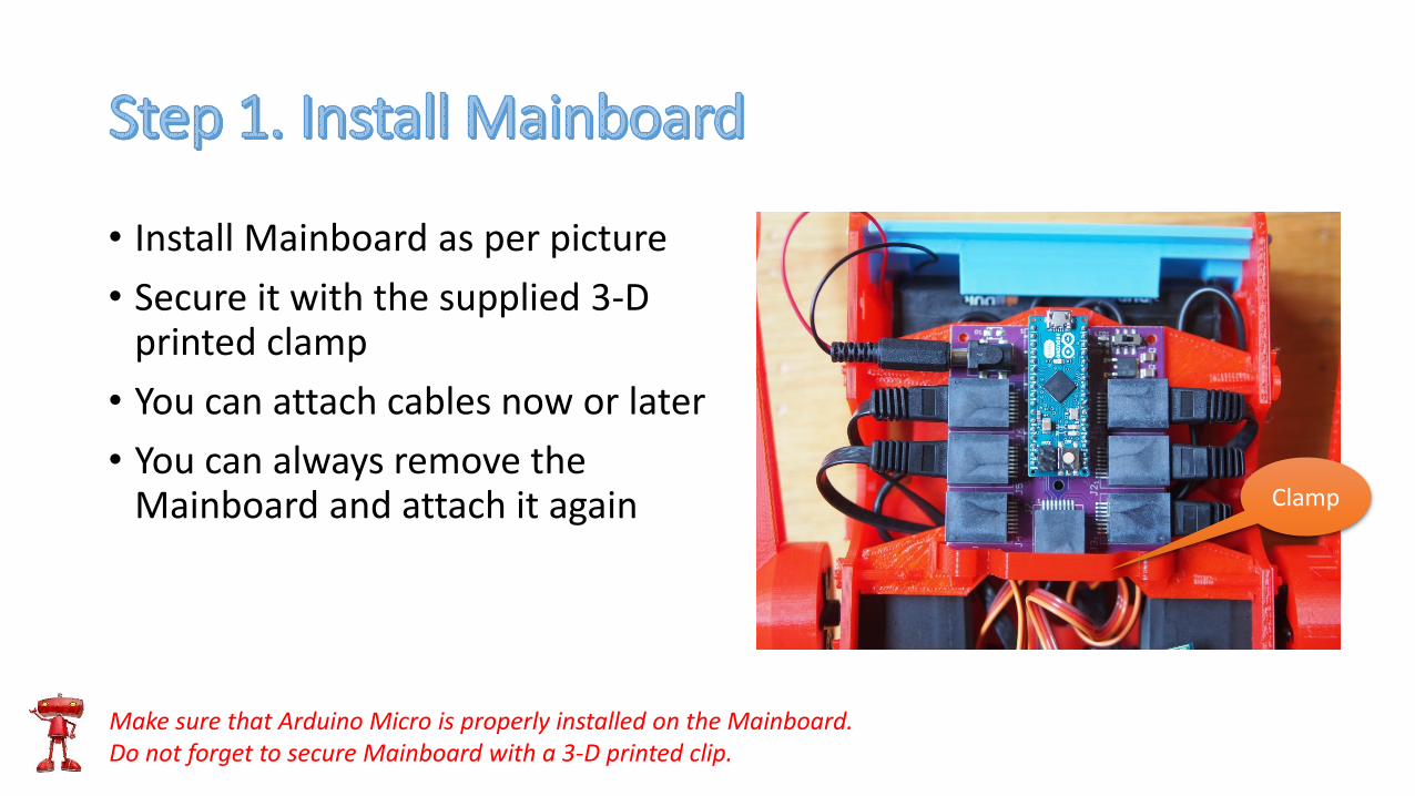
• Install Mainboard as per picture
• Secure it with the supplied 3-D printed clamp
• You can attach cables now or later
• You can always remove the Mainboard and attach it again
Make sure that Arduino Micro is properly installed on the Mainboard.Do not forget to secure Mainboard with a 3-D printed clip.
Clamp
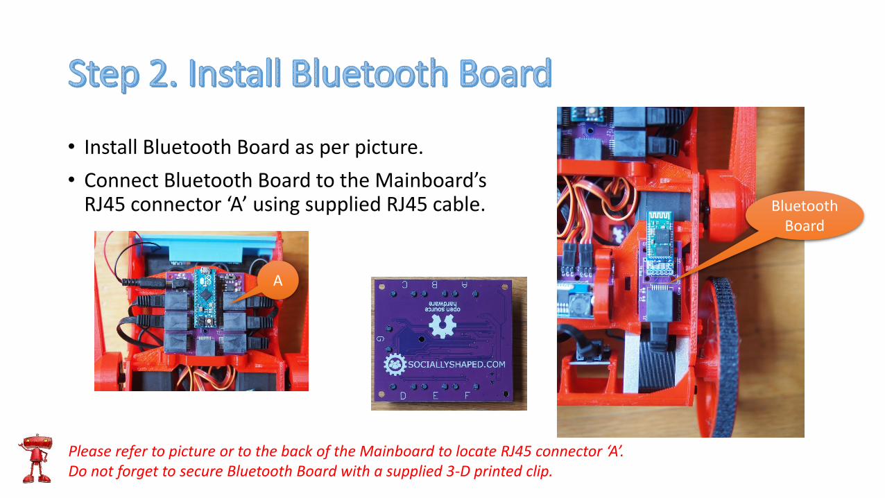
• Install Bluetooth Board as per picture.
• Connect Bluetooth Board to the Mainboard’s RJ45 connector ‘A’ using supplied RJ45 cable.
Please refer to picture or to the back of the Mainboard to locate RJ45 connector ‘A’.Do not forget to secure Bluetooth Board with a supplied 3-D printed clip.
Bluetooth Board
A
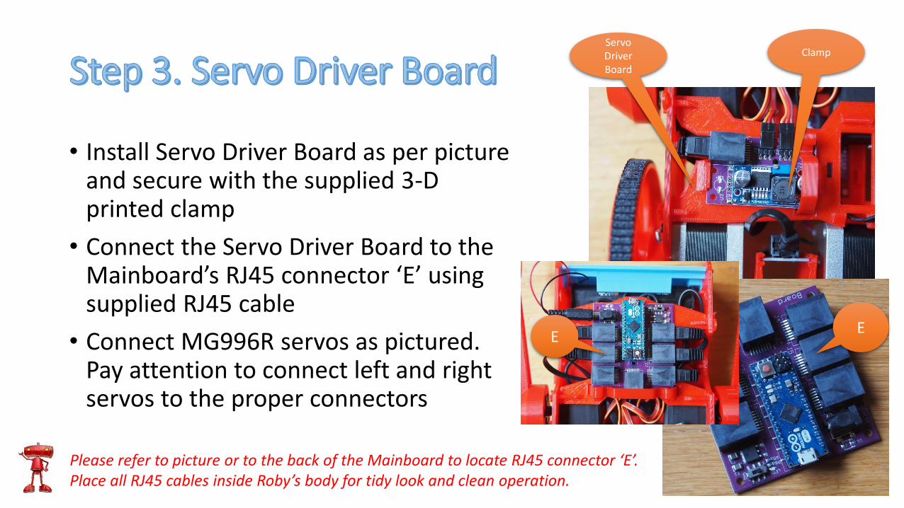
• Install Servo Driver Board as per picture and secure with the supplied 3-D printed clamp
• Connect the Servo Driver Board to the Mainboard’s RJ45 connector ‘E’ using supplied RJ45 cable
• Connect MG996R servos as pictured. Pay attention to connect left and right servos to the proper connectors
Please refer to picture or to the back of the Mainboard to locate RJ45 connector ‘E’.Place all RJ45 cables inside Roby’s body for tidy look and clean operation.
Servo Driver Board
Clamp
EE
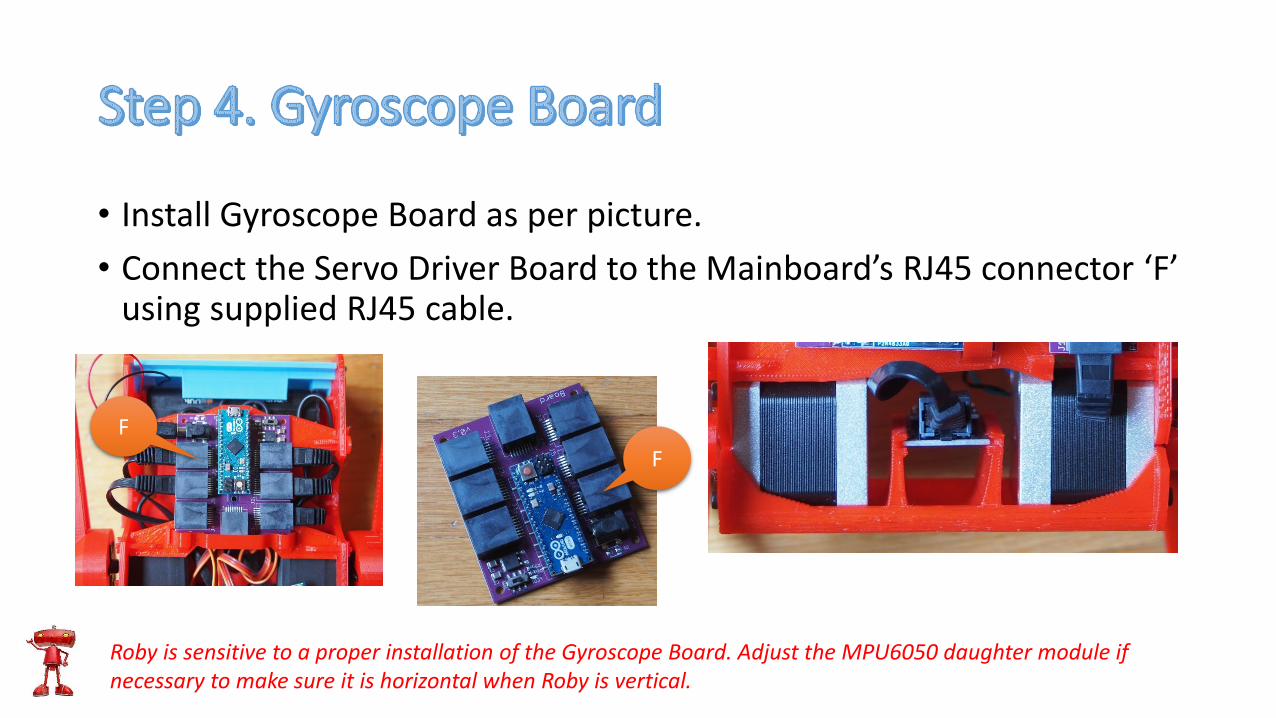
• Install Gyroscope Board as per picture.
• Connect the Servo Driver Board to the Mainboard’s RJ45 connector ‘F’ using supplied RJ45 cable.
Roby is sensitive to a proper installation of the Gyroscope Board. Adjust the MPU6050 daughter module if necessary to make sure it is horizontal when Roby is vertical.
F
F
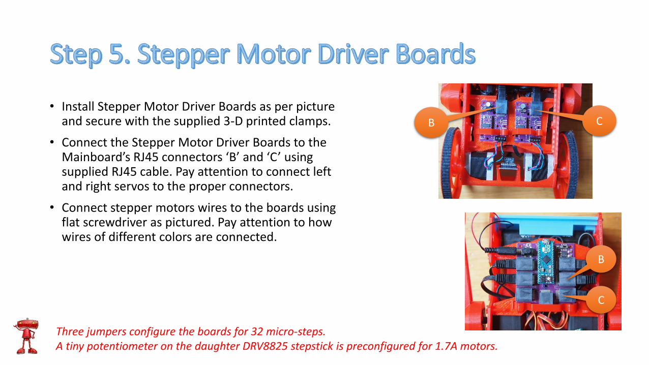
• Install Stepper Motor Driver Boards as per picture and secure with the supplied 3-D printed clamps.
• Connect the Stepper Motor Driver Boards to the Mainboard’s RJ45 connectors ‘B’ and ‘C’ using supplied RJ45 cable. Pay attention to connect left and right servos to the proper connectors.
• Connect stepper motors wires to the boards using flat screwdriver as pictured. Pay attention to how wires of different colors are connected.
Three jumpers configure the boards for 32 micro-steps.A tiny potentiometer on the daughter DRV8825 stepstick is preconfigured for 1.7A motors.
B
B C
C
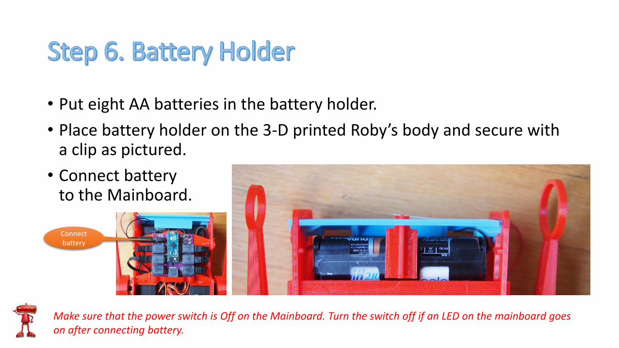
• Put eight AA batteries in the battery holder.
• Place battery holder on the 3-D printed Roby’s body and secure with a clip as pictured.
• Connect battery to the Mainboard.
Make sure that the power switch is Off on the Mainboard. Turn the switch off if an LED on the mainboard goes on after connecting battery.
Connect battery
• Follow Configuring Joystick Bluetooth Commander step by step guide to breath life into your Roby.
• Use Troubleshooting Guide if you encounter any problem.