Right Angle Drills - buckeye-tools.com Angle Drills. Page 2 ... PA5/PB5 represents all models of the...
48
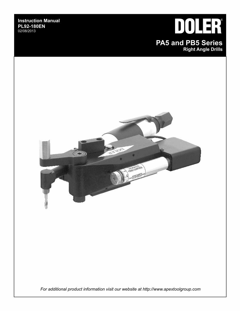
For additional product information visit our website at http://www.apextoolgroup.com Instruction Manual PL92-180EN 02/08/2013 PA5 and PB5 Series Right Angle Drills
Transcript of Right Angle Drills - buckeye-tools.com Angle Drills. Page 2 ... PA5/PB5 represents all models of the...
For additional product information visit our website at http://www.apextoolgroup.com
Instruction ManualPL92-180EN02/08/2013
PA5 and PB5 SeriesRight Angle Drills
Page 2
PL92-180EN02/08/2013
Cleco®
General Information
For this Instruction ManualThis Instruction Manual is the Original Instruction Manual intended for all persons who will operate and maintain these tools.
This Instruction Manualprovides important notes for the safe and efficient use of these tools.• describes the function and operation of the PA5/PB5 series tools.• serves as a reference guide for technical data, service intervals and spare parts ordering.• provides information on optional equipment.•
Identification text:PA5/PB5 represents all models of the right angle pnuematic nutrunner as described in this manual
Ú indicates a required action• indicates a list<..> indicates a reference number from the exploded parts drawingsArial indicates an important feature or instruction written in Arial Bold
Identification graphic:¢ indicates a directional movement
ò indicates a function or force
Copyright protection:Apex Tool Group, LLC reserves the right to modify, supplement or improve this document or the product without prior notice. This document may not be reproduced in any way, shape or form, in full or parts thereof, or copied to another natural or machine readable language or to a data carrier, whether electronic, mechanical, optical or otherwise without the express permission of Apex Tool Group, LLC.
Page 3
PL92-180EN02/08/2013
Cleco®
Nomenclature
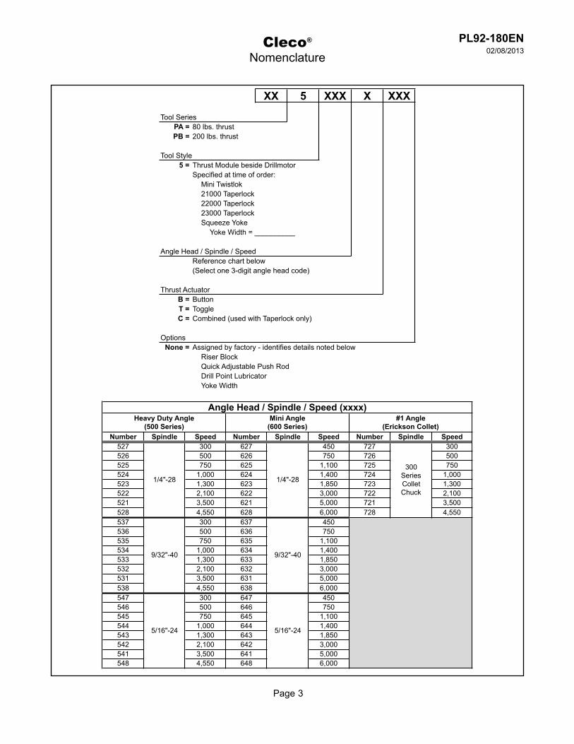
XX 5 XXX X XXX
Tool SeriesPA = 80 lbs. thrustPB = 200 lbs. thrust
Tool Style5 = Thrust Module beside Drillmotor
Specified at time of order:Mini Twistlok21000 Taperlock22000 Taperlock23000 TaperlockSqueeze Yoke
Yoke Width = __________
Angle Head / Spindle / SpeedReference chart below(Select one 3-digit angle head code)
Thrust ActuatorB = ButtonT = ToggleC = Combined (used with Taperlock only)
OptionsNone = Assigned by factory - identifies details noted below
Riser BlockQuick Adjustable Push RodDrill Point LubricatorYoke Width
Number Spindle Speed Number Spindle Speed Number Spindle Speed527 300 627 450 727 300526 500 626 750 726 500525 750 625 1,100 725 750524 1,000 624 1,400 724 1,000523 1,300 623 1,850 723 1,300522 2,100 622 3,000 722 2,100521 3,500 621 5,000 721 3,500528 4,550 628 6,000 728 4,550537 300 637 450536 500 636 750535 750 635 1,100534 1,000 634 1,400533 1,300 633 1,850532 2,100 632 3,000531 3,500 631 5,000538 4,550 638 6,000547 300 647 450546 500 646 750545 750 645 1,100544 1,000 644 1,400543 1,300 643 1,850542 2,100 642 3,000541 3,500 641 5,000548 4,550 648 6,000
Angle Head / Spindle / Speed (xxxx)Heavy Duty Angle
(500 Series)Mini Angle
(600 Series)#1 Angle
(Erickson Collet)
1/4"-28
9/32"-40
5/16"-24
1/4"-28
9/32"-40
5/16"-24
300SeriesColletChuck
Page 4
PL92-180EN02/08/2013
Cleco®
Contents
1 Safety 6
1.1 Warning and notes .................................................................................................61.2 Basic requirements for safe working practices ...................................................... 71.3 Operator training ....................................................................................................71.4 Personal protective equipment ..............................................................................71.5 Designated use ......................................................................................................81.6 Codes and standards ............................................................................................81.7 Noise and vibration ................................................................................................8
2 Scope of supply, transport and storage 8
2.1 Items supplied .......................................................................................................82.2 Transport ...............................................................................................................82.3 Storage ..................................................................................................................8
3 Product description 9
3.1 General description ...............................................................................................93.2 Operation and functional elements ........................................................................93.3 Drill motor configuration .......................................................................................103.4 Angle head dimensions .......................................................................................103.5 Changing spindle speeds ....................................................................................103.6 Thrust system operation ...................................................................................... 11
4 Accessories 12
5 Before initial operation 13
5.1 Ambient conditions ..............................................................................................135.2 Air supply .............................................................................................................135.3 Connecting the air supply to the tool ...................................................................135.4 Tool set up - Squeeze mode ................................................................................145.4.1 Squeeze mode set up ..........................................................................................145.4.2 Squeeze mode operation ....................................................................................145.5 Tool set up - Push away mode ............................................................................145.6 Tool set up - Taperlock mode ...............................................................................155.6.1 Taperlock mode set up ........................................................................................155.6.2 Taperlock mode operation ...................................................................................155.6.3 Taperlock bushing tips .........................................................................................165.6.4 Mini twistlok bushing tips .....................................................................................165.7 Push Rod and Actuator Arm set up .....................................................................175.8 Actuator arm ........................................................................................................18
6 First operation 18
6.1 Puting into use .....................................................................................................18
Page 5
PL92-180EN02/08/2013
Cleco®
Contents
7 Troubleshooting 19
8 Maintenance 20
8.1 Service schedule .................................................................................................208.1.1 Calculating a customer specific maintenance plan .............................................. 208.2 Lubricants ............................................................................................................218.3 Maintenance tools required .................................................................................21
9 Repair instructions 22
9.1 PA5/PB5 Disassembly .........................................................................................229.2 PA5/PB5 Assembly ..............................................................................................229.3 Motor Assembly ...................................................................................................239.4 Timing of the step reduction gear assembly ........................................................ 23
10 Spare parts
10.1 PA5/PB5 Rignt Angle Drill ....................................................................................2410.2 42AR Housing .....................................................................................................2610.3 42AR Motor Assembly .........................................................................................2810.4 Single Stage Gearing (Speed Codes: 1 - 2 - 3 - 4) .............................................. 3010.5 Double Stage Gearing (Speed Codes: 5 - 6 - 7) ................................................. 3210.6 Single Stage Gearing (6,000 RPM) .....................................................................3410.7 600 Series Mini Angle Head Attachment .............................................................3610.8 500 Series Heavy Duty Angle Head Attachment ................................................. 3810.9 #1 Erickson 300 Series Collet Chuck Angle Head Attachment ............................ 40
11 Technical data 42
11.1 PA5 and PB5 Specifications ................................................................................42
12 Service 43
12.1 Replacement parts ..............................................................................................4312.2 Tool repairs ..........................................................................................................4312.3 Warranty repairs ..................................................................................................43
13 Disposal 44
Page 6
PL92-180EN02/08/2013
Cleco®
Safety
1 Safety1.1 Warnings and notes
Warning notes are identified by a signal word and a pictogram.The signal word indicates the severity and probability of the impending danger.• The pictogram indicates the type of danger.•
---------------------------------------------------------------------------------------------------------------------------------------WARNING identifies a potentially hazardous situation which, if not avoided, may result in serious injury.------------------------------------------------------------------------------------------------------------------------------------------------------------------------------------------------------------------------------------------------------------------------------CAUTION identifies a potentially hazardous situation which, if not avoided, may result in minor or moderate injury or property and environmental damage.------------------------------------------------------------------------------------------------------------------------------------------------------------------------------------------------------------------------------------------------------------------------------NOTE identifies general information which may include application tips or useful information but no hazardous situations.------------------------------------------------------------------------------------------------------------------------------------------------------------------------------------------------------------------------------------------------------------------------------Important information that must be read and understood by all personnel installing, operating or maintaining this equipment.---------------------------------------------------------------------------------------------------------------------------------------
Page 7
PL92-180EN02/08/2013
Cleco®
Safety
1.2 Basic requirements for safe working practicesAll personnel involved with the installation, operation or maintenance of these tools must read and understand all safety instructions contained in this manual. Failure to comply with these instructions could result in serious injury or property damage.These safety instructions are not intended to be all inclusive. Study and comply with all applicable National, State and Local regulations.---------------------------------------------------------------------------------------------------------------------------------------Work Area:ÚEnsure there is enough space in the work area.ÚKeep the work area clean.ÚKeep the work area well ventilated.
Personnel Safety:ÚInspect the air supply hoses and fittings. Do not use damaged, frayed or deteriorated hoses.ÚMake sure the air supply hose is securely attached to the tool.ÚEnsure a secure standing position and maintain balance.ÚKeep the tool clean and dry to provide the best possible grip.
Safety working with and around fastening tools:ÚUse only power tool drill bitsÚInspect drill bit for visible damage and cracks. Replace damaged items immediately.ÚDisconnect the air supply before installing or replacing the drill bit.ÚDo not attach the drill bit at a slant.ÚMake sure the drill bit is fully assembled on the drive and locked in postion.---------------------------------------------------------------------------------------------------------------------------------------
1.3 Operator trainingAll personnel must be properly trained before operating the PA5/PB5 tools. The PA5/PB5 tools are to be repaired by fully trained personnel only.
1.4 Personal protective equipmentWhen working
Wear eye protection to protect against flying metal splinters.• Wear hearing protection•
Danger of injury by being caught by moving equipment.Wear a hairnet• Do not wear close fitting clothing• Do not wear jewelry•
Page 8
PL92-180EN02/08/2013
Cleco®
Safety
1.5 Designated useThe PA5/PB5 are designed exclusively for drilling holes.The PA5 series drills are suitable for drilling aluminum to 1/4” diameter.The PB5 series drills are suitable for drilling larger holes in aluminum and for drilling titanium, inconel, steel, etc.
Do not modify the PA5/PB5, any guard or accessory.• Use only with accessory parts which are approved by the manufacturer.• Do not use as a hammer, pry-bar or any other improper usage.•
1.6 Codes and standardsIt is mandatory that all national, state and local codes and standards be followed.
1.7 Noise and vibrationNoise level < 85 dB(A) free speed (without load) according to ISO 12100: 2011Vibration values: Fixture mounted, not applicable
2 Scope of supply, transport and storage2.1 Items supplied
Check shipment for transit damage and ensure that all items have been supplied:1 PA5 or PB51 PL92-180EN instruction manual1 Declaration of Conformity1 Lubrication sheet1 Warranty statement
2.2 Transport
Transport and store the PA5/PB5 in the original packaging. The packaging is recyclable.
2.3 StorageFor short term storage (less than 2 hours) and protection against damage:ÚPlace the PA5/PB5 in a location on the workbench to avoid accidental depression of the lever.
For storage longer than 2 hours:ÚDisconnect the air supply from the PA5/PB5
Object Time Period Storage TemperaturePA5/PB5 without air supply No guideline -13°F to 104°F (-25°C to 40°C)
Page 9
PL92-180EN02/08/2013
Cleco®
Scope of Supply, Transport and Storage
3 Product description3.1 General description
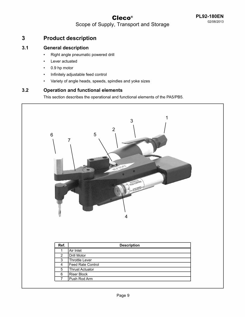
Right angle pneumatic powered drill• Lever actuated• 0.9 hp motor• Infinitely adjustable feed control• Variety of angle heads, speeds, spindles and yoke sizes•
3.2 Operation and functional elementsThis section describes the operational and functional elements of the PA5/PB5.
6
1
2
4
5
Ref. Description1 Air Inlet2 Drill Motor3 Throttle Lever4 Feed Rate Control5 Thrust Actuator6 Riser Block7 Push Rod Arm
3
7
Page 10
PL92-180EN02/08/2013
Cleco®
Product Description
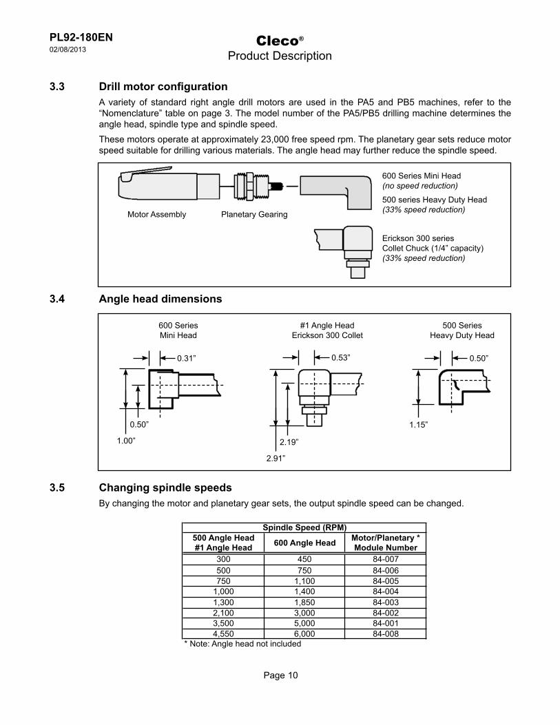
3.3 Drill motor configurationA variety of standard right angle drill motors are used in the PA5 and PB5 machines, refer to the “Nomenclature” table on page 3. The model number of the PA5/PB5 drilling machine determines the angle head, spindle type and spindle speed.These motors operate at approximately 23,000 free speed rpm. The planetary gear sets reduce motor speed suitable for drilling various materials. The angle head may further reduce the spindle speed.
3.4 Angle head dimensions
3.5 Changing spindle speedsBy changing the motor and planetary gear sets, the output spindle speed can be changed.
Motor Assembly Planetary Gearing
600 Series Mini Head(no speed reduction)
500 series Heavy Duty Head(33% speed reduction)
Erickson 300 seriesCollet Chuck (1/4” capacity)(33% speed reduction)
600 SeriesMini Head
0.50”
1.00”
0.31”
#1 Angle HeadErickson 300 Collet
500 SeriesHeavy Duty Head
2.19”
2.91”
0.53”
1.15”
0.50”
500 Angle Head#1 Angle Head 600 Angle Head Motor/Planetary *
Module Number300 450 84-007500 750 84-006750 1,100 84-005
1,000 1,400 84-0041,300 1,850 84-0032,100 3,000 84-0023,500 5,000 84-0014,550 6,000 84-008
* Note: Angle head not included
Spindle Speed (RPM)

Page 11
PL92-180EN02/08/2013
Piston
Push Rod
Push Rod Arm
Linkage
Cleco®
Product Description
3.6 Thrust system operationThe thrust and linear motion of the piston is transferred to the push rod using a simple linkage.• The piston is controlled by the thrust acuator valve.• The hydraulic feed control restricts air cylinder movement to the desired feed rate.•
Page 12
PL92-180EN02/08/2013
Cleco®
Accessories
4 Accessories
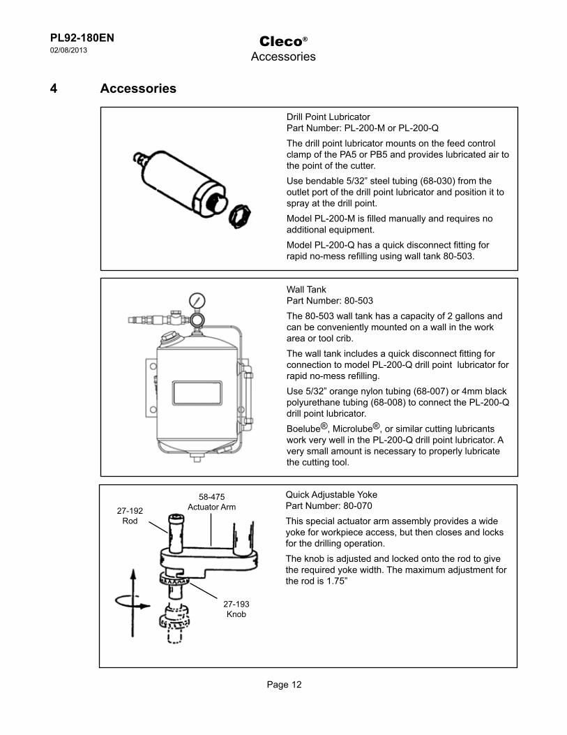
Drill Point LubricatorPart Number: PL-200-M or PL-200-QThe drill point lubricator mounts on the feed control clamp of the PA5 or PB5 and provides lubricated air to the point of the cutter.Use bendable 5/32” steel tubing (68-030) from the outlet port of the drill point lubricator and position it to spray at the drill point.Model PL-200-M is filled manually and requires no additional equipment.Model PL-200-Q has a quick disconnect fitting for rapid no-mess refilling using wall tank 80-503.
Wall TankPart Number: 80-503The 80-503 wall tank has a capacity of 2 gallons and can be conveniently mounted on a wall in the work area or tool crib.The wall tank includes a quick disconnect fitting for connection to model PL-200-Q drill point lubricator for rapid no-mess refilling.Use 5/32” orange nylon tubing (68-007) or 4mm black polyurethane tubing (68-008) to connect the PL-200-Q drill point lubricator.Boelube®, Microlube®, or similar cutting lubricants work very well in the PL-200-Q drill point lubricator. A very small amount is necessary to properly lubricate the cutting tool.
Quick Adjustable YokePart Number: 80-070This special actuator arm assembly provides a wide yoke for workpiece access, but then closes and locks for the drilling operation.The knob is adjusted and locked onto the rod to give the required yoke width. The maximum adjustment for the rod is 1.75”
27-192Rod
27-193Knob
58-475Actuator Arm

Page 13
PL92-180EN02/08/2013
Cleco®
Before Initial Operation
5 Before initial operation5.1 Ambient conditions
Ambient temperature: 41°F (5°C) to a maximum of 104°F (40°C)
Acceptable relative humidity: 25% to 90%, non-condensing
5.2 Air supply
To attain consistent results, maintain a constant working pressure using a suitable air line unit consisting of a filter, regulator and lubricator.ÚThe inside diameter of the air hose must be free of residue, clean if necessary.ÚSpray a few drops of light air tool oil into the air inlet adapter.ÚAdjust the lubricator to a minimum setting to reduce the amount of excess oil in the exhaust air.
Oil identification
5.3 Connecting the air supply to the tool---------------------------------------------------------------------------------------------------------------------------------------The air hose can disconnect from the tool by itself and whip around uncontrollably.ÚTurn off the compressed air before connecting to the tool.ÚSecurely connect the air hose to the tool.ÚTurn on the compressed air.
---------------------------------------------------------------------------------------------------------------------------------------
Parameter Description
Air Hose Minimum inside diameter: 3/8" (9,5 mm)Maximum length: 16.4' (5 m)
Working pressure range 58 to 101.5 psi (400 to 700 kPa)Recommended: 90 psi (620 kPa)
Compressed air Air quality according to ISO 8573-1, quality class 2.4.3The compressed air must be clean and dry.
Part No. Packaged Designation Vendor540397 1 Quart (0.94 liter) Airlube 10W/NR-420LB DR Fuchs Lubricants Co.533485 1 US Gallon (3.78 liter) Airlube 10W/NR-420LB DR Fuchs Lubricants Co.
Page 14
PL92-180EN02/08/2013
5.4 Tool set up - Squeeze Mode
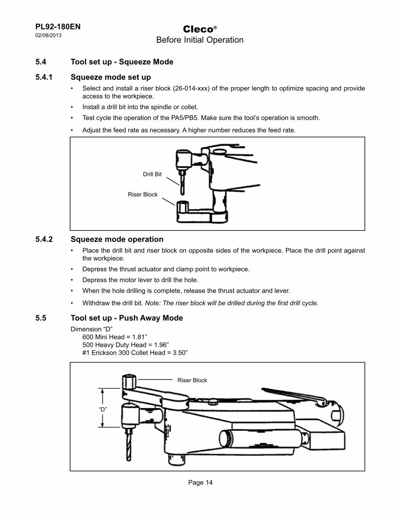
5.4.1 Squeeze mode set upSelect and install a riser block (26-014-xxx) of the proper length to optimize spacing and provide • access to the workpiece.Install a drill bit into the spindle or collet.• Test cycle the operation of the PA5/PB5. Make sure the tool’s operation is smooth.•
Adjust the feed rate as necessary. A higher number reduces the feed rate.•
5.4.2 Squeeze mode operationPlace the drill bit and riser block on opposite sides of the workpiece. Place the drill point against • the workpiece.Depress the thrust actuator and clamp point to workpiece.• Depress the motor lever to drill the hole.• When the hole drilling is complete, release the thrust actuator and lever.•
Withdraw the drill bit. • Note: The riser block will be drilled during the first drill cycle.
5.5 Tool set up - Push Away ModeDimension “D”
600 Mini Head = 1.81”500 Heavy Duty Head = 1.96”#1 Erickson 300 Collet Head = 3.50”
Cleco®
Before Initial Operation
Riser Block
Drill Bit
“D”
Riser Block
Page 15
PL92-180EN02/08/2013
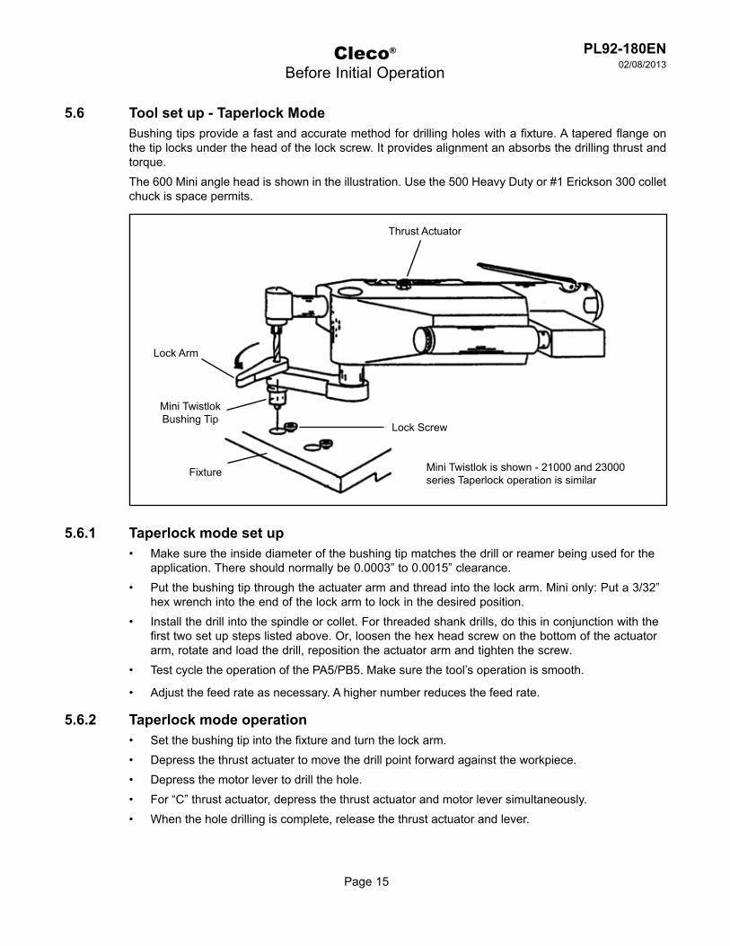
5.6 Tool set up - Taperlock ModeBushing tips provide a fast and accurate method for drilling holes with a fixture. A tapered flange on the tip locks under the head of the lock screw. It provides alignment an absorbs the drilling thrust and torque.The 600 Mini angle head is shown in the illustration. Use the 500 Heavy Duty or #1 Erickson 300 collet chuck is space permits.
5.6.1 Taperlock mode set upMake sure the inside diameter of the bushing tip matches the drill or reamer being used for the • application. There should normally be 0.0003” to 0.0015” clearance.Put the bushing tip through the actuater arm and thread into the lock arm. Mini only: Put a 3/32” • hex wrench into the end of the lock arm to lock in the desired position.Install the drill into the spindle or collet. For threaded shank drills, do this in conjunction with the • first two set up steps listed above. Or, loosen the hex head screw on the bottom of the actuator arm, rotate and load the drill, reposition the actuator arm and tighten the screw.Test cycle the operation of the PA5/PB5. Make sure the tool’s operation is smooth.•
Adjust the feed rate as necessary. A higher number reduces the feed rate.•
5.6.2 Taperlock mode operationSet the bushing tip into the fixture and turn the lock arm.• Depress the thrust actuater to move the drill point forward against the workpiece.• Depress the motor lever to drill the hole.• For “C” thrust actuator, depress the thrust actuator and motor lever simultaneously.• When the hole drilling is complete, release the thrust actuator and lever.•
Cleco®
Before Initial Operation
Thrust Actuator
Lock Arm
Mini Twistlok Bushing Tip
Lock Screw
Fixture Mini Twistlok is shown - 21000 and 23000 series Taperlock operation is similar

Page 16
PL92-180EN02/08/2013
5.6.3 Taperlock bushing tipsUse standard 21000, 22000 or 23000 series bushing tips. Use 1/8” rod in holes of Taperlock collar.
5.6.4 Mini twistlok bushing tipsMiniature version of 21000 series taperlock tips• Aligns tool to fixture - absorbs thrust and torque• Used for small holes and close hole spacings (up to 0.313” diameter holes)•
Cleco®
Before Initial Operation
Actuator Arm21000 series: 58-25822000 series: 58-43023000 series: 58-498
Taperlock Collar21000 series: 27-11622000 series: 27-18323000 series: 27-209
Taperlock Bushing Tip(Purchase from a quality bushing company)
0.437”
0.44”
Part Number: 22-703-xxx (Replace xxx with the drill diameter)Example: For 3/16” drill, order 22-703-188
0.457”0.452”
0.438”Dia.
10-32 Threadfor 17-035lock screw
Fixture Hole Specifications
Lock Arm
Mini Twistlok Bushing Tip
Fixture
17-035Lock Screw
Chip Clearance(0.25 typical)
Page 17
PL92-180EN02/08/2013
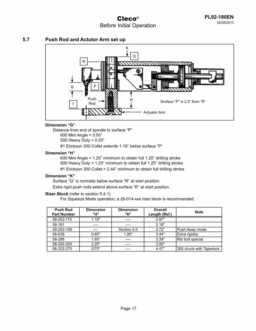
5.7 Push Rod and Actutor Arm set up
Dimension “G”Distance from end of spindle to surface “P”
600 Mini Angle = 0.50”500 Heavy Duty = 0.25”#1 Erickson 300 Collet extends 1.19” below surface “P”
Dimension “H”600 Mini Angle = 1.25” minimum to obtain full 1.25” drilling stroke500 Heavy Duty = 1.25” minimum to obtain full 1.25” drilling stroke#1 Erickson 300 Collet = 2.44” minimum to obtain full drilling stroke
Dimension “K”Surface “Q” is normally below surface “R” at start position.Extra rigid push rods extend above surface “R” at start position.
Riser Block (refer to section 5.4.1)For Squeeze Mode operation, a 26-014-xxx riser block is recommended.
Cleco®
Before Initial Operation
K
Q
HT
P
R
G
Actuator Arm
PushRod Sruface “P” is 2.0” from “R”
Push RodPart Number
Dimension"H"
Dimension"K"
OverallLength (Ref.) Note
58-202-115 1.15" ---- 2.87"58-181 ---- ---- 2.19"58-202-100 ---- Section 5.5 2.72" Push Away mode58-638 0.80" 1.00" 3.44" Extra rigidity58-288 1.60" ---- 3.39" Rib bolt special58-202-220 2.20" ---- 3.92"58-202-275 2/75" ---- 4.47" 300 chuck with Taperlock

Page 18
PL92-180EN02/08/2013
Cleco®
First Operation
5.8 Actuator armUsed with the squeeze and push away modes.
6 First operation6.1 Putting into use
ÚMake sure the air supply is securely attached and the compressed is turned on.
ÚMake sure tool set up is complete for the application.
ÚBegin the drilling cycle as described in Sections 5.4, 5.5, 5.6 and 5.7.
Actuator Arm - “W” Description:58-180 - 5/16”-24 Thread (Std.)58-220 - 0.50” Thru Hole
2.06”(ref.)
0.50”
“W”Mounting Diameterto Push Rod
Page 19
PL92-180EN02/08/2013
Cleco®
Troubleshooting
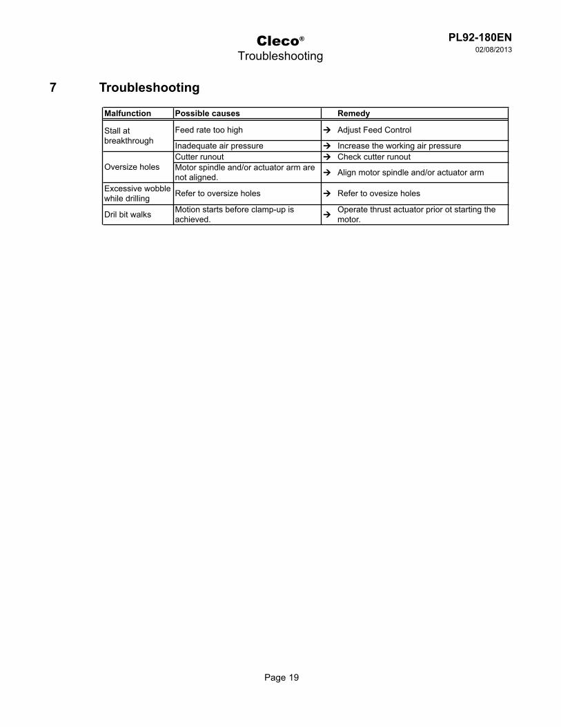
7 Troubleshooting
Malfunction Possible causes Remedy
Feed rate too high Ú Adjust Feed Control
Inadequate air pressure Ú Increase the working air pressureCutter runout Ú Check cutter runoutMotor spindle and/or actuator arm are not aligned. Ú Align motor spindle and/or actuator arm
Excessive wobble while drilling Refer to oversize holes Ú Refer to ovesize holes
Dril bit walks Motion starts before clamp-up is achieved. Ú
Operate thrust actuator prior ot starting the motor.
Stall at breakthrough
Oversize holes
Page 20
PL92-180EN02/08/2013
Cleco®
Maintenance
8 Maintenance---------------------------------------------------------------------------------------------------------------------------------------Danger of injury from accidental start up.Turn off the compressed air before performing any maintenance.
---------------------------------------------------------------------------------------------------------------------------------------
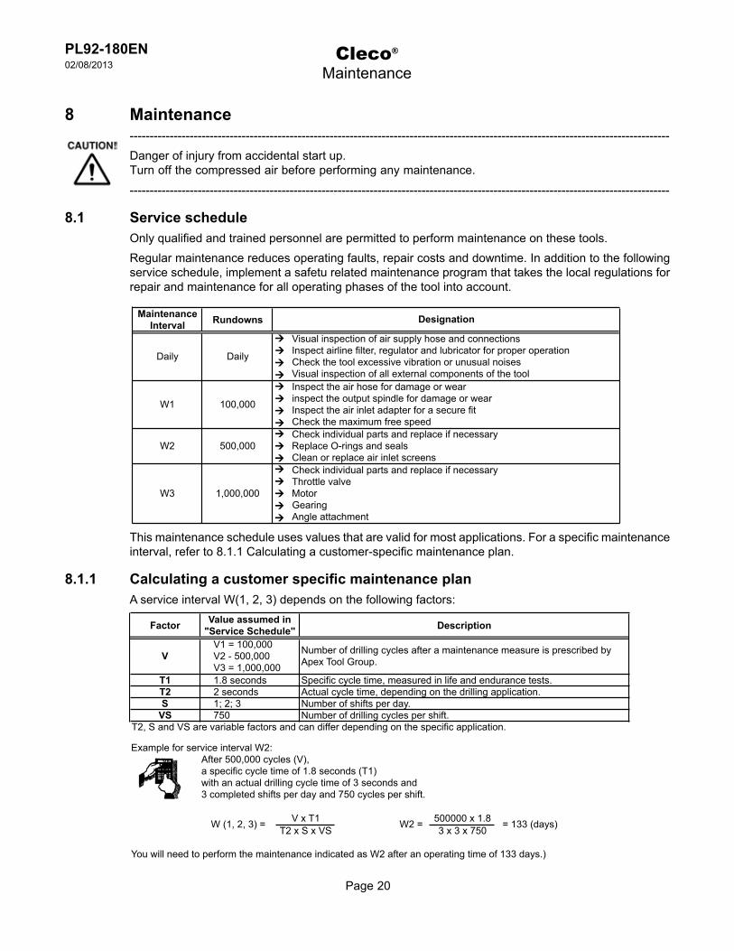
8.1 Service scheduleOnly qualified and trained personnel are permitted to perform maintenance on these tools.Regular maintenance reduces operating faults, repair costs and downtime. In addition to the following service schedule, implement a safetu related maintenance program that takes the local regulations for repair and maintenance for all operating phases of the tool into account.
This maintenance schedule uses values that are valid for most applications. For a specific maintenance interval, refer to 8.1.1 Calculating a customer-specific maintenance plan.
8.1.1 Calculating a customer specific maintenance planA service interval W(1, 2, 3) depends on the following factors:
Maintenance Interval Rundowns
Daily Daily
ÚÚÚÚ
Visual inspection of air supply hose and connectionsInspect airline filter, regulator and lubricator for proper operationCheck the tool excessive vibration or unusual noisesVisual inspection of all external components of the tool
W1 100,000
ÚÚÚÚ
Inspect the air hose for damage or wearinspect the output spindle for damage or wearInspect the air inlet adapter for a secure fitCheck the maximum free speed
W2 500,000ÚÚÚ
Check individual parts and replace if necessaryReplace O-rings and sealsClean or replace air inlet screens
W3 1,000,000
ÚÚÚÚÚ
Check individual parts and replace if necessaryThrottle valveMotorGearingAngle attachment
Designation
Factor Value assumed in "Service Schedule" Description
VV1 = 100,000V2 - 500,000V3 = 1,000,000
Number of drilling cycles after a maintenance measure is prescribed by Apex Tool Group.
T1 1.8 seconds Specific cycle time, measured in life and endurance tests.T2 2 seconds Actual cycle time, depending on the drilling application.S 1; 2; 3 Number of shifts per day.
VS 750 Number of drilling cycles per shift.T2, S and VS are variable factors and can differ depending on the specific application.
Example for service interval W2:After 500,000 cycles (V),a specific cycle time of 1.8 seconds (T1)with an actual drilling cycle time of 3 seconds and3 completed shifts per day and 750 cycles per shift.
V x T1 500000 x 1.8T2 x S x VS 3 x 3 x 750
You will need to perform the maintenance indicated as W2 after an operating time of 133 days.)
W (1, 2, 3) = W2 = = 133 (days)
Page 21
PL92-180EN02/08/2013
Cleco®
Maintenance
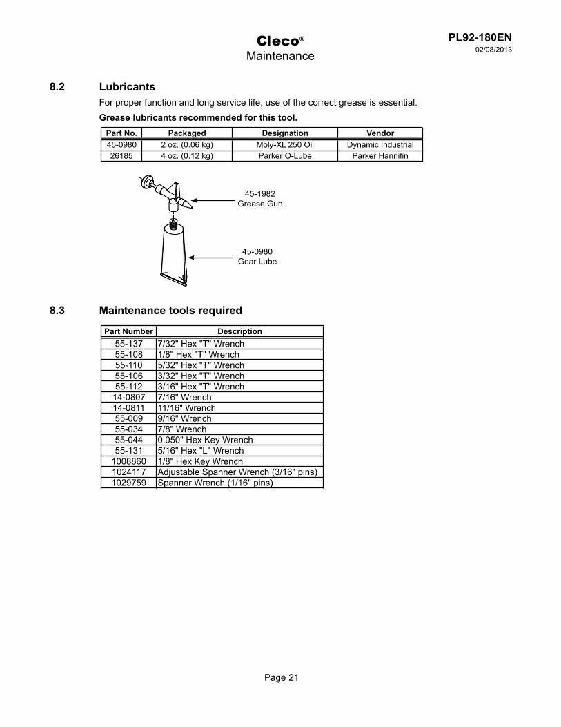
8.2 LubricantsFor proper function and long service life, use of the correct grease is essential.Grease lubricants recommended for this tool.
8.3 Maintenance tools required
Part No. Packaged Designation Vendor45-0980 2 oz. (0.06 kg) Moly-XL 250 Oil Dynamic Industrial26185 4 oz. (0.12 kg) Parker O-Lube Parker Hannifin
Part Number Description55-137 7/32" Hex "T" Wrench55-108 1/8" Hex "T" Wrench55-110 5/32" Hex "T" Wrench55-106 3/32" Hex "T" Wrench55-112 3/16" Hex "T" Wrench
14-0807 7/16" Wrench14-0811 11/16" Wrench55-009 9/16" Wrench55-034 7/8" Wrench55-044 0.050" Hex Key Wrench55-131 5/16" Hex "L" Wrench
1008860 1/8" Hex Key Wrench1024117 Adjustable Spanner Wrench (3/16" pins)1029759 Spanner Wrench (1/16" pins)
45-1982Grease Gun
45-0980Gear Lube
Page 22
PL92-180EN02/08/2013
Cleco®
Repair Instructions
9 Repair instructions9.1 PA5/PB5 Disassembly (reference Section 10.1)
Remove the tubing from the rear of the drill motor and remove the drill motor assembly.• Remove the rear guard.• Loosen the cap screw and slide the feed control bracket from the piston.• Loosen the set screw in the feed control clamp and remove the feed control.• Remove the feed control clamp.• PB5 models: Remove the booster housing.• PB5 models: Insert a pin in the cross hole of the booster piston to unthread it from the piston.• Bulkhead removal:•
PA5 models: Remove the bulkhead from the actuator housing using 11/16” wrench 55-011.PB5 models: Remove the bulkhead from the actuator housing using spanner wrench 1024117.
Piston removal:• PA5 models: Unthread the piston from the pivot linkage assembly.PB5 models: Unthread the piston from the pivot linkage assembly using a large screwdriver.
Remove the piston and piston bushing from the actuator housing.• Push out the actuator pin from the actuator housing and remove the pivot linkage assembly.• Pull out the push rod.•
Using an arbor press, remove the push rod bushing from the acutator housing.•
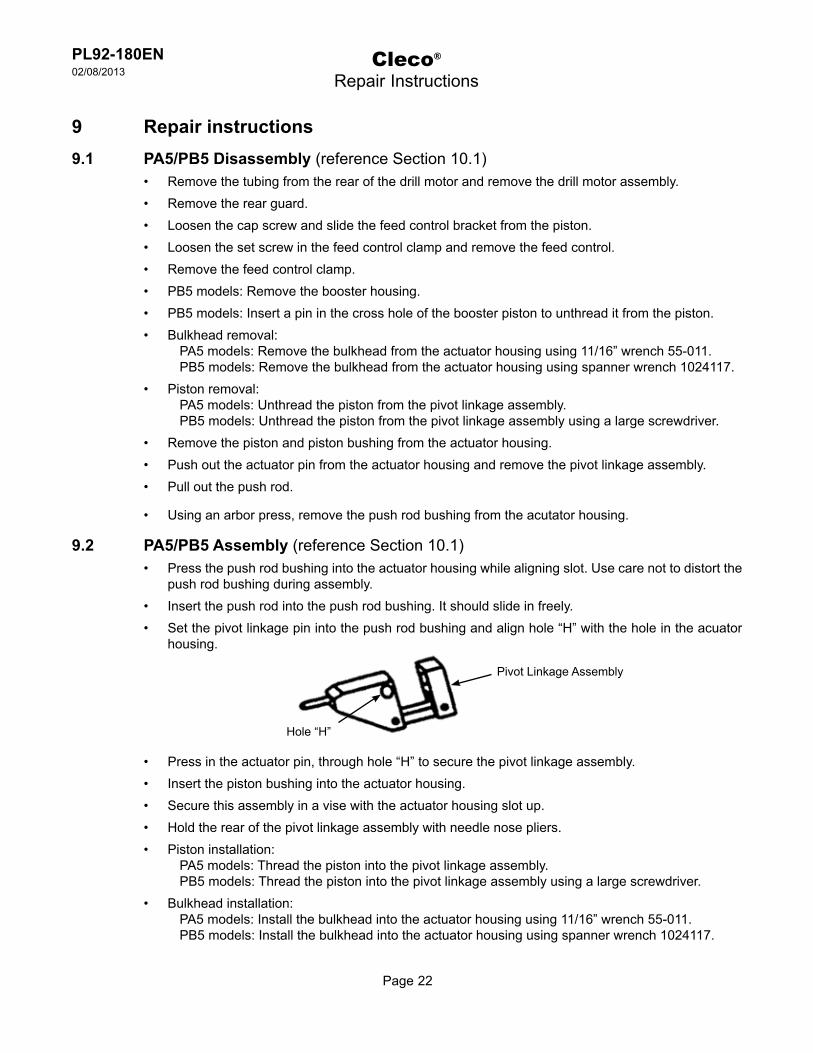
9.2 PA5/PB5 Assembly (reference Section 10.1)Press the push rod bushing into the actuator housing while aligning slot. Use care not to distort the • push rod bushing during assembly.Insert the push rod into the push rod bushing. It should slide in freely.• Set the pivot linkage pin into the push rod bushing and align hole “H” with the hole in the acuator • housing.
Press in the actuator pin, through hole “H” to secure the pivot linkage assembly.• Insert the piston bushing into the actuator housing.• Secure this assembly in a vise with the actuator housing slot up.• Hold the rear of the pivot linkage assembly with needle nose pliers.• Piston installation:•
PA5 models: Thread the piston into the pivot linkage assembly.PB5 models: Thread the piston into the pivot linkage assembly using a large screwdriver.
Bulkhead installation:• PA5 models: Install the bulkhead into the actuator housing using 11/16” wrench 55-011.PB5 models: Install the bulkhead into the actuator housing using spanner wrench 1024117.
Pivot Linkage Assembly
Hole “H”
Page 23
PL92-180EN02/08/2013
Cleco®
Repair Instructions
9.2 PA5/PB5 Assembly (reference Section 10.1) - continuedPB5 models: Insert a pin in the cross hole of the booster piston to thread it into the piston.• PB5 models: Slide the booster housing over the booster piston. Use care not to damage the o-rings. • Thread the booster housing onto the bulkhead.Install the feed control clamp, feed control and feed control bracket.• Assembly the rear guard.• Place the drill motor into the actuator housing. Install the four cap screws but do not tighten.• Align the spindle with the push rod arm in all directions, refer to Section 5.7.• Tighten the four cap screws to secure the drill motor.• I rapid traverse is desired, adjust the feed control bracket and feed control.•
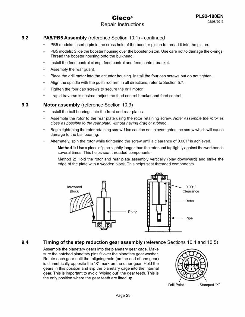
9.3 Motor assembly (reference Section 10.3)Install the ball bearings into the front and rear plates.• Assemble the rotor to the rear plate using the rotor retaining screw. • Note: Assemble the rotor as close as possible to the rear plate, without having drag or rubbing.
Begin tightening the rotor retaining screw. Use caution not to overtighten the screw which will cause • damage to the ball bearing.Alternately, spin the rotor while tightening the screw until a clearance of 0.001” is achieved.•
Method 1: Use a piece of pipe slightly longer than the rotor and tap lightly against the workbench several times. This helps seat threaded components.Method 2: Hold the rotor and rear plate assembly vertically (play downward) and strike the edge of the plate with a wooden block. This helps seat threaded components.
9.4 Timing of the step reduction gear assembly (reference Sections 10.4 and 10.5)Assemble the planetary gears into the planetary gear cage. Make sure the notched planetary pins fit over the planetary gear washer. Rotate each gear until the aligning hole (on the end of one gear) is diametrically opposite the “X” mark on the other gear. Hold the gears in this position and slip the planetary cage into the internal gear. This is important to avoid “wiping out” the gear teeth. This is the only position where the gear teeth are lined up.
HardwoodBlock
Rotor
Rotor
Pipe
0.001”Clearance
Stamped “X”Drill Point
Page 24
PL92-180EN02/08/2013
Page 24
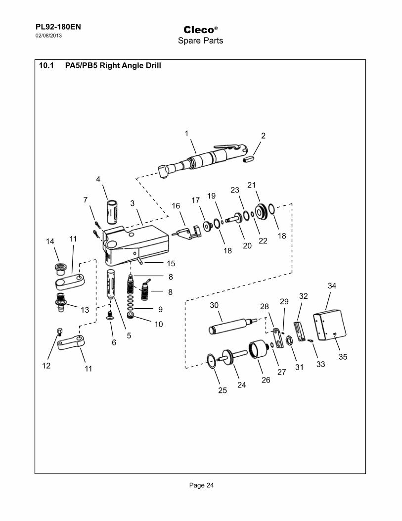
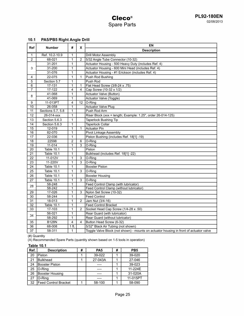
10.1 PA5/PB5 Right Angle Drill
Cleco®
Spare Parts
8
2
32
12
15
1
1617 19
23 21
18 20 22 18
2425
2627 31 33
35
30 28 29
34
4
37
8
9
10
6
11
5
14 11
13
PL92-180EN02/08/2013
Page 25
ENDescription
1 Ref. 10.2-10.9 1 Drill Motor Assembly2 68-021 1 2 5/32 Angle Tube Connector (10-32)
31-201 1 Actuator Housing - 500 Heavy Duty (includes Ref. 4)31-200 1 Actuator Housing - 600 Mini Head (includes Ref. 4)31-076 1 Actuator Housing - #1 Erickson (includes Ref. 4)
4 22-075 1 1 Push Rod Bushing5 Section 5.7 1 Push Rod6 17-131 1 1 Flat Head Screw (3/8-24 x .75)7 17-122 4 4 Cap Screw (10-32 x 1/2)
41-068 1 Actuator Valve (Button)41-069 1 Actuator Valve (Toggle)
9 11-013PT 4 12 O-Ring10 26-058 1 Actuator Valve Plug11 Sections 5.7, 5.8 1 Push Rod Arm12 26-014-xxx 1 Riser Block (xxx = length; Example: 1.25", order 26-014-125)13 Section 5.6.3 1 Taperlock Bushing Tip14 Section 5.6.3 1 Taperlock Collar15 12-019 1 1 Actuator Pin16 82-070 1 Pivot Linkage Assembly17 22-036 1 Piston Bushing (includes Ref. 18[1] -19)18 22598 2 6 O-Ring19 11-014 1 3 O-Ring20 Table 10.1 1 Piston21 Table 10.1 1 Bulkhead (includes Ref. 18[1] -22)22 11-012V 1 3 O-Ring23 11-220V 1 3 O-Ring24 Table 10.1 1 Booster Piston25 Table 10.1 1 3 O-Ring26 Table 10.1 1 Booster Housing27 Table 10.1 1 3 O-Ring
58-248 1 Feed Control Clamp (with lubricator)58-242 1 Feed Control Clamp (without lubricator)
29 17-026 1 3 Nylon Set Screw (10-32)30 58-244 1 Feed Control31 18-013 1 2 Jam Nut (3/4-16)32 Table 10.1 1 Feed Control Bracket33 17-103 1 2 Socket Head Cap Screw (1/4-28 x .50)
56-021 1 Rear Guard (with lubricator)58-292 1 Rear Guard (without lubricator)
35 B128N 4 4 Button Head Screw (6-32)36 68-008 1 ft. 5/32" Black Air Tubing (not shown)37 58-311 1 Toggle Valve Block (not shown) - mounts on actuator housing in front of actuator valve
(#) Quantity(X) Recommended Spare Parts (quantity shown based on 1-5 tools in operation)
28
34
10.1 PA5/PB5 Right Angle Drill
Ref Number # X
3
8
Cleco®
Spare Parts
Table 10.1Ref. Description # PA5 # PB520 Piston 1 39-022 1 39-02021 Bulkhead 1 27-043A 1 27-04624 Booster Piston ---- 1 39-02325 O-Ring ---- 1 11-224E26 Booster Housing ---- 1 31-020A27 O-Ring ---- 1 11-015PT32 Feed Control Bracket 1 58-100 1 58-090

Page 26
PL92-180EN02/08/2013
Cleco®
Spare Parts
3
2
1
5
89
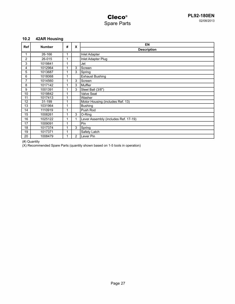
10.2 42AR Housing
4
7
6
1110
14
15
12
1617
13
20
19
18
Page 27
PL92-180EN02/08/2013
Cleco®
Spare Parts
ENDescription
1 26-166 1 Inlet Adapter2 26-015 1 Inlet Adapter Plug3 1019841 1 Jet4 1012964 1 3 Screen5 1013687 1 3 Spring6 1018068 1 Exhaust Bushing7 1014560 1 3 Screen8 1017142 1 3 Muffler9 1001391 1 3 Steel Ball (3/8")
10 1019842 1 Valve Seat11 1017413 1 Washer12 31-199 1 Motor Housing (includes Ref. 13)13 1031964 1 Bushing14 1110919 1 Push Rod15 1008261 1 3 O-Ring16 1025122 1 1 Lever Assembly (includes Ref. 17-19)17 1009091 1 Pin18 1017374 1 3 Spring19 1017371 1 Safety Latch20 1008479 1 2 Lever Pin
(#) Quantity(X) Recommended Spare Parts (quantity shown based on 1-5 tools in operation)
10.2 42AR Housing
Ref Number # X
Page 28
PL92-180EN02/08/2013
Cleco®
Spare Parts
3
2
1
7
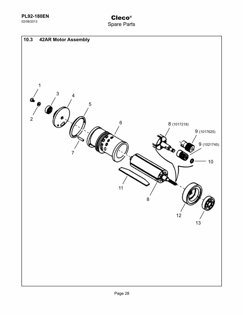
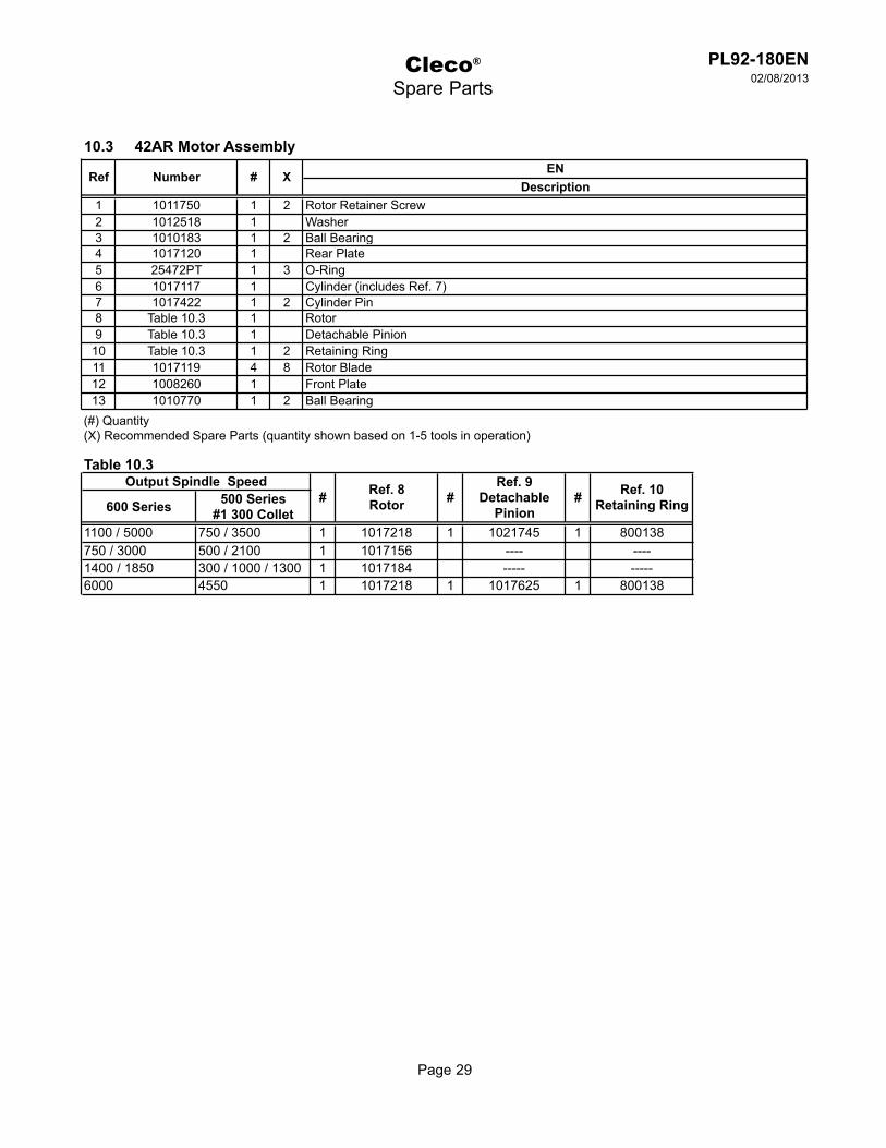
10.3 42AR Motor Assembly
4
6
5
9 (1017625)
11
8
1312
10
9 (1021745)
8 (1017218)
Page 29
PL92-180EN02/08/2013
Cleco®
Spare Parts
ENDescription
1 1011750 1 2 Rotor Retainer Screw2 1012518 1 Washer3 1010183 1 2 Ball Bearing4 1017120 1 Rear Plate5 25472PT 1 3 O-Ring6 1017117 1 Cylinder (includes Ref. 7)7 1017422 1 2 Cylinder Pin8 Table 10.3 1 Rotor9 Table 10.3 1 Detachable Pinion
10 Table 10.3 1 2 Retaining Ring11 1017119 4 8 Rotor Blade12 1008260 1 Front Plate13 1010770 1 2 Ball Bearing
(#) Quantity(X) Recommended Spare Parts (quantity shown based on 1-5 tools in operation)
10.3 42AR Motor Assembly
Ref Number # X
Table 10.3
600 Series 500 Series#1 300 Collet
1100 / 5000 750 / 3500 1 1017218 1 1021745 1 800138750 / 3000 500 / 2100 1 1017156 ---- ----1400 / 1850 300 / 1000 / 1300 1 1017184 ----- -----6000 4550 1 1017218 1 1017625 1 800138
Ref. 10Retaining Ring
Output Spindle Speed# Ref. 8
Rotor #Ref. 9
DetachablePinion
#

Page 30
PL92-180EN02/08/2013
Cleco®
Spare Parts
3
2
1
7
10.4 Single Stage Gearing (Speed Codes: 1 - 2 - 3 - 4)
4
65
11
8
13
12
7
1L
L L
L Lubricate with 45-0980 Gear Lube

Page 31
PL92-180EN02/08/2013
Cleco®
Spare Parts
ENDescription
1 1008262 1 2 Ball Bearing2 Table 10.4 1 Planetary Gear Cage3 Table 10.4 2 4 Planetary Gear4 Table 10.4 22 44 Planetary Gear Rollers5 Table 10.4 2 4 Planetary Gear Pin6 Table 10.4 1 Washer7 1007964 1 1 Retaining Ring8 1008854 1 2 Ball Bearing9 1110185 1 Retaining Nut
10 94080005 1 2 Wave Washer11 Table 10.4 1 Gear Housing (includes Ref. 12)12 1463PT 1 1 Grease Fitting13 1110065 1 Lock Nut
(#) Quantity(X) Recommended Spare Parts (quantity shown based on 1-5 tools in operation)(T) Teeth
10.4 Single Stage Gearing Assembly
Ref Number # X
Table 10.4
Ref. Description # Part Number # Part Number # Part Number # Part Number2 Planetary Gear Cage 1 1110228 1 1110229 1 1110231 1 11102263 Planetary Gear 2 1008250 (16T) 2 1008252 (19T) 2 1110139 (21T) 2 1008952PT4 Planetary Gear Rollers 22 1004984 22 1004984 22 1004984 22 10050245 Planetary Gear Pin 2 1004983 2 1004983 2 1004983 2 10050106 Washer 1 1110069 1 1110070 1 1110071 1 111007111 Gear Housing 1 1110040 1 1110042 1 1110042 1 1110063
(T) Teeth
30002100
2
14001000
4
18501300
3
600 Series (RPM)500 & #1 Series (RPM)
Speed Code 1
50003500
Page 32
PL92-180EN02/08/2013
Cleco®
Spare Parts
13
5 151
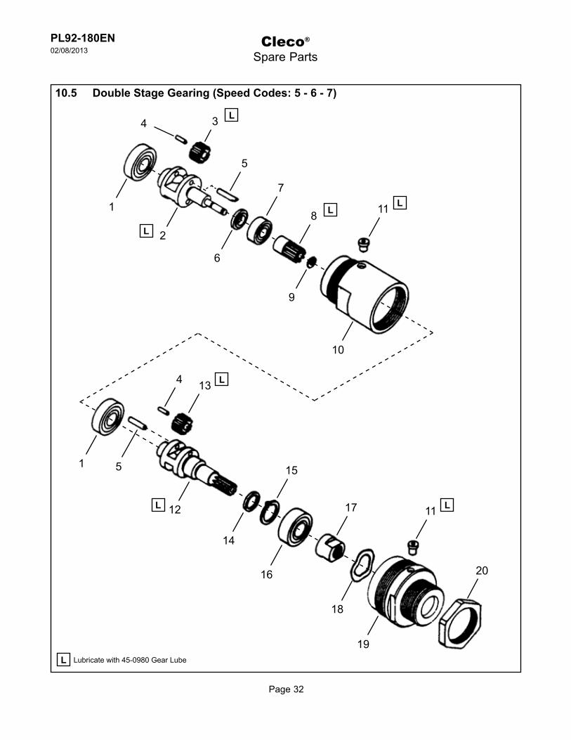
10.5 Double Stage Gearing (Speed Codes: 5 - 6 - 7)
17 11
20
14
16
19
18
12
4 L
L L
L Lubricate with 45-0980 Gear Lube
10
11 L8 L
3 L
9
6
2L
1
5
7
4

Page 33
PL92-180EN02/08/2013
ENDescription
1 1008262 2 4 Ball Bearing2 Table 10.5 1 Planetary Gear Cage3 Table 10.5 2 4 Planetary Gear4 1004984 44 88 Planetary Gear Roller5 1004983 4 8 Planetary Gear Pin6 Table 10.5 1 Washer7 847095 1 2 Ball Bearing8 1017856 1 2 Pinion Gear9 800138 1 2 Retaining Ring
10 Table 10.5 1 Gear Housing (includes 1 Ref. 11)11 1463PT 2 2 Grease Fitting12 1110228 1 Planetary Gear Cage13 1008250 2 4 Planetary Gear (16T)14 1110069 1 Washer15 1007964 1 1 Retaining Ring16 1008854 1 2 Ball Bearing17 1110185 1 Retaining Nut18 94080005 1 2 Wave Washer19 1110040 1 Gear Housing (includes 1 Ref. 11)20 1110065 1 Lock Nut
(#) Quantity(X) Recommended Spare Parts (quantity shown based on 1-5 tools in operation)(T) Teeth
10.5 Double Stage Gearing Assembly
Ref Number # X
Table 10.5
Ref. Description # Part Number # Part Number # Part Number2 Planetary Gear Cage 1 1017842 1 1017841 1 10178403 Planetary Gear 2 1008250 (16T) 2 1008252 (19T) 2 1008241 (21T)6 Washer 1 1017051 1 1017053 1 1017052
10 Gear Housing 1 1008955 1 1008956 1 1008956(T) Teeth
Speed Code 5 6 7
600 Series (RPM) 1100 750 450500 & #1 Series (RPM) 750 500 300
Cleco®
Spare Parts

Page 34
PL92-180EN02/08/2013
Cleco®
Spare Parts
34
1
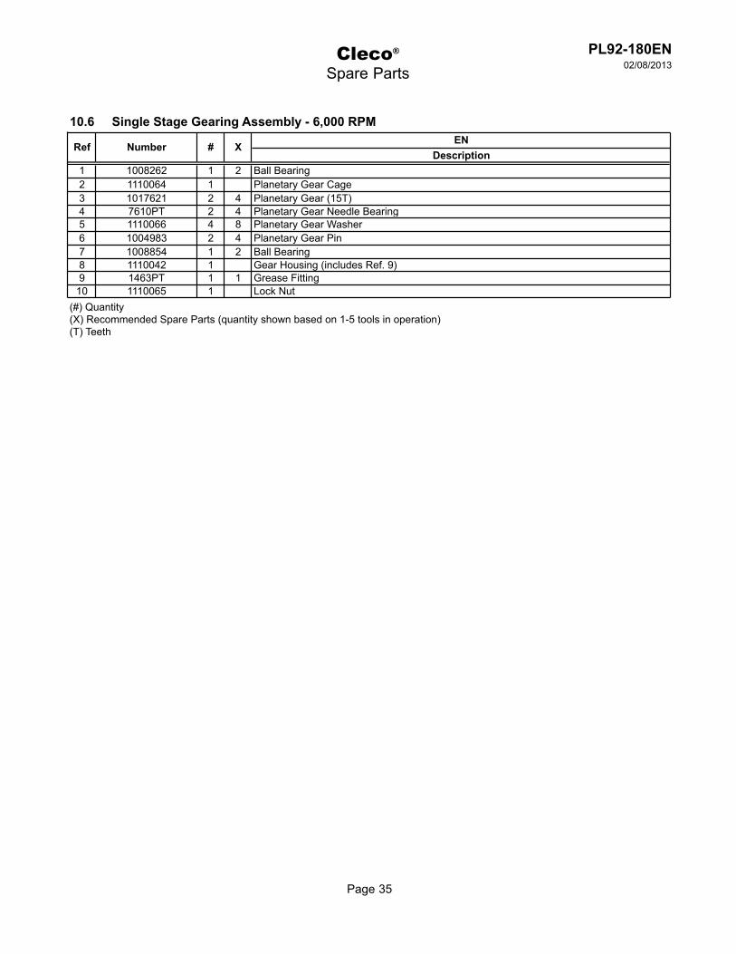
10.6 Single Stage Gearing (6,000 RPM)
9
7
8
10
2
5L
L
L
L Lubricate with 45-0980 Gear Lube
5
6
Page 35
PL92-180EN02/08/2013
Cleco®
Spare Parts
ENDescription
1 1008262 1 2 Ball Bearing2 1110064 1 Planetary Gear Cage3 1017621 2 4 Planetary Gear (15T)4 7610PT 2 4 Planetary Gear Needle Bearing5 1110066 4 8 Planetary Gear Washer6 1004983 2 4 Planetary Gear Pin7 1008854 1 2 Ball Bearing8 1110042 1 Gear Housing (includes Ref. 9)9 1463PT 1 1 Grease Fitting
10 1110065 1 Lock Nut(#) Quantity(X) Recommended Spare Parts (quantity shown based on 1-5 tools in operation)(T) Teeth
10.6 Single Stage Gearing Assembly - 6,000 RPM
Ref Number # X
Page 36
PL92-180EN02/08/2013
Cleco®
Spare Parts
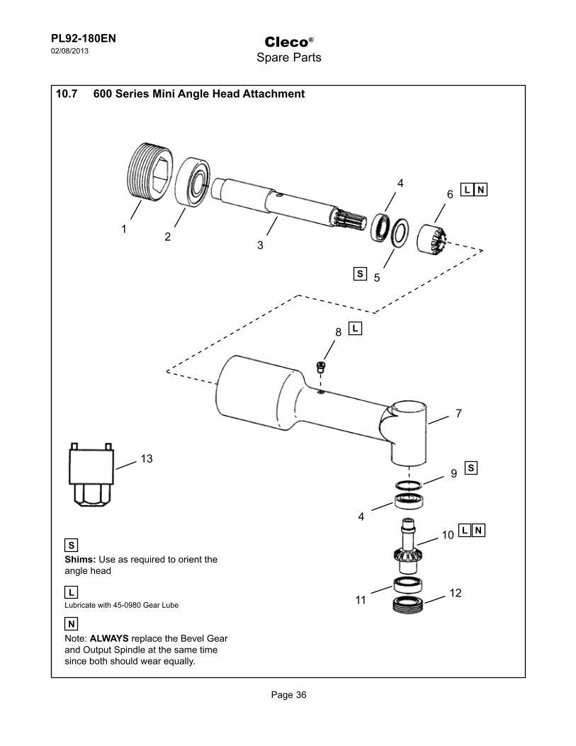
Note: ALWAYS replace the Bevel Gear and Output Spindle at the same time since both should wear equally.
N
8
2
5
13
N
7
9
12
410 L
L
L
SShims: Use as required to orient the angle head
S
10.7 600 Series Mini Angle Head Attachment
11
N6 L4
S
Lubricate with 45-0980 Gear Lube
13
Page 37
PL92-180EN02/08/2013
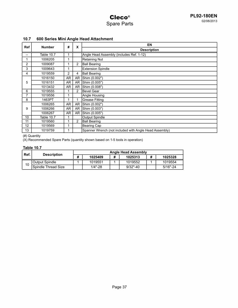
ENDescription
-- Table 10.7 1 Angle Head Assembly (includes Ref. 1-12)1 1006205 1 Retaining Nut2 1009087 1 2 Ball Bearing3 1009643 1 Extension Spindle4 1019559 2 4 Ball Bearing
1016150 AR AR Shim (0.002")1016151 AR AR Shim (0.005")1013432 AR AR Shim (0.008")
6 1019555 1 2 Bevel Gear7 1019556 1 Angle Housing8 1463PT 1 1 Grease Fitting
1006265 AR AR Shim (0.002")1006266 AR AR Shim (0.003")1006267 AR AR Shim (0.005")
10 Table 10.7 1 Output Spindle11 1019560 1 2 Ball Bearing12 1019569 1 Bearing Cap13 1019759 1 Spanner Wrench (not included with Angle Head Assembly)
(#) Quantity(X) Recommended Spare Parts (quantity shown based on 1-5 tools in operation)
10.7 600 Series Mini Angle Head Attachment
Ref Number # X
5
9
Cleco®
Spare Parts
Table 10.7
# 1025409 # 1025313 # 1025328Output Spindle 1 1019551 1 1019552 1 1019554Spindle Thread Size 1/4"-28 9/32"-40 5/16"-24
Angle Head AssemblyDescriptionRef.
10
Page 38
PL92-180EN02/08/2013
Cleco®
Spare Parts
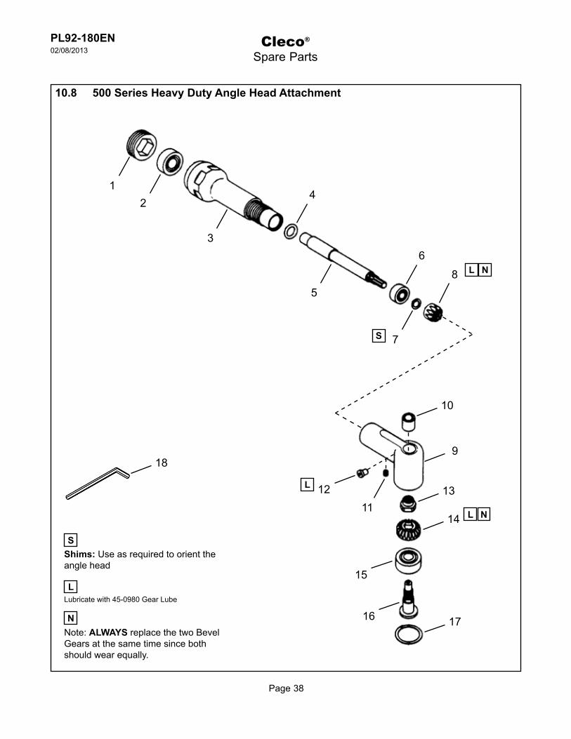
Note: ALWAYS replace the two Bevel Gears at the same time since both should wear equally.
N
2
7
1
3
N
10
9
1312
14 L
L
SShims: Use as required to orient the angle head
S
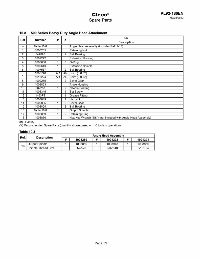
10.8 500 Series Heavy Duty Angle Head Attachment
15
N8 L
4
Lubricate with 45-0980 Gear Lube
18
5
6
11
16 17
L
Page 39
PL92-180EN02/08/2013
ENDescription
-- Table 10.8 1 Angle Head Assembly (includes Ref. 1-17)1 1006205 1 Retaining Nut2 847095 1 2 Ball Bearing3 1009242 1 Extension Housing4 1006680 1 3 O-Ring5 1009643 1 Extension Spindle6 1007537 1 2 Ball Bearing
1008748 AR AR Shim (0.002")1013224 AR AR Shim (0.005")
8 1009255 1 2 Bevel Gear9 1008853 1 Angle Housing
10 382253 1 2 Needle Bearing11 1008345 1 1 Set Screw12 1463PT 1 1 Grease Fitting13 1008849 1 1 Hex Nut14 1009095 1 2 Bevel Gear15 1008854 1 2 Ball Bearing16 Table 10.8 1 Output Spindle17 1008859 1 2 Retaining Ring18 1008860 1 Hex Key Wrench (1/8") (not included with Angle Head Assembly)
(#) Quantity(X) Recommended Spare Parts (quantity shown based on 1-5 tools in operation)
10.8 500 Series Heavy Duty Angle Head Attachment
Ref Number # X
7
Cleco®
Spare Parts
Table 10.8
# 1021289 # 1021292 # 1021291Output Spindle 1 1008850 1 1008948 1 1008856Spindle Thread Size 1/4"-28 9/32"-40 5/16"-24
Ref. Description Angle Head Assembly
16

Page 40
PL92-180EN02/08/2013
Cleco®
Spare Parts
Note: ALWAYS replace the Bevel Gear and Pinion Gear at the same time since both should wear equally.
N
21
3
N
10
11
11
12
6L
L
SShims: Use as required to orient the angle head
10.9 #1 Erickson 300 Series Collet Chuck Angle Head Attachment
9
N6 L
4
Lubricate with 45-0980 Gear Lube
19
5
5S
8 L
13
18
17
16
15
14
7

Page 41
PL92-180EN02/08/2013
ENDescription
1 14-0904 1 Lock Nut2 506PT 1 2 Ball Bearing3 7664PT 1 Spindle Housing4 7663PT 1 Spindle5 538PT 2 4 Ball Bearing6 03-1116 1 2 Pinion and Bevel Gear Set7 1024PT 1 Angle Housing (includes Ref. 8-9)8 1463PT 1 1 Grease Fitting9 1356PT 1 2 Wear Ring
10 504PT 1 2 Ball Bearing11 1755PT 2 4 Lubricator Disc12 1355PT 1 2 Shim Packet13 1025PT 1 Lock Ring14 1029PT 1 Collet Spindle15 1062PT 1 2 Woodruff Key16 308PT 1 2 Collet (1/4")17 1053PT 1 Collet Nosepiece18 1058PT 1 Collet Cap
14-0807 1 Wrench (7/16")14-0811 1 Wrench (11/16")
(#) Quantity(X) Recommended Spare Parts (quantity shown based on 1-5 tools in operation)
19
10.9 #1 Erickson 300 Series Collet Chuck Angle Head Attachment
Ref Number # X
Cleco®
Spare Parts

Page 42
PL92-180EN02/08/2013
Cleco®
Technical Data
11 Technical data11.1 PA5 and PB5 Specifications
PA5 - 70 lbs. thrust for drilling small holes in aluminum• PB5 - 160 lbs. thrust for drilling large holes in aluminum and holes in titanium and steel• Stroke - 1.25”• Compact power feed• Accessible into very confined areas• Modular design• Variety of angle heads, speeds, spindles and yoke sizes• 0.9 hp motor• Infinitely adjustable feed control• Drill point lubricator to maximize hole quality• PA5 weight - 5.7 lbs.• PB5 weight - 7.1 lbs.•

Page 43
PL92-180EN02/08/2013
Cleco®
Service
12 Service12.1 Replacement parts
Use only original Doler replacement parts. Failure to comply can result in reduced power and increased service requirements. The tool warranty may be voided if replacement parts are not manufactured or approved by Apex Tool Group.
12.2 Tool repairs
Only qualified and trained personnel are to repair this equipment.
12.3 Warranty repairsAll warranty repairs are to be performed by an authorized Apex Tool Group service center. Contact your local representative for assistance with warranty repair claims.
Page 44
PL92-180EN02/08/2013
Cleco®
Disposal
13 Disposal---------------------------------------------------------------------------------------------------------------------------------------Injuries and environmental damage from improper disposal.Components and auxillary materials of the tool pose risks to health and the environment.ÚCapture auxillary materials (oils, greases) when drained and dispose of them properly.ÚSeparate the packaging components and dispose of them properly.ÚComply with all applicable local regulations.
Observe local disposal guidelines for all components of this tool and its packaging.
---------------------------------------------------------------------------------------------------------------------------------------

Page 45
PL92-180EN02/08/2013


PL92-180EN/Printed in USA 02/2013/Copyright © Apex Tool Group, LLC
Apex Tool Group, LLC1000 Lufkin RoadApex, NC 27539Phone: 919-387-0099Fax: 919-387-2614www.apextoolgroup.com
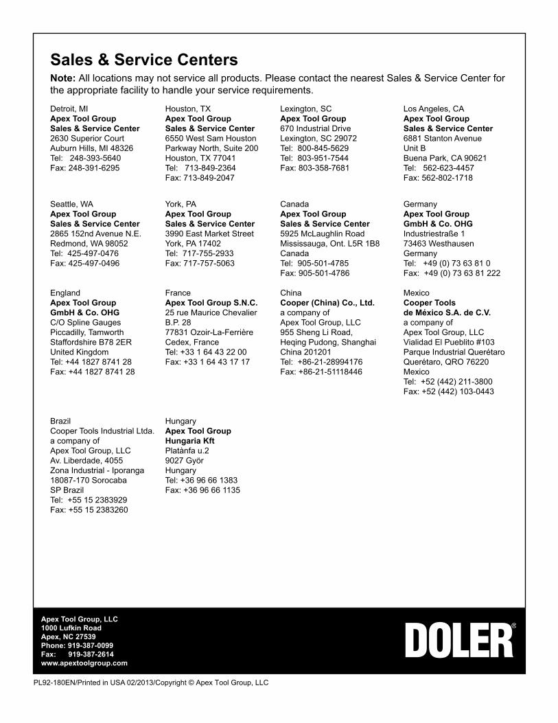
Sales & Service CentersNote: All locations may not service all products. Please contact the nearest Sales & Service Center for the appropriate facility to handle your service requirements.
Detroit, MI Houston, TX Lexington, SC Los Angeles, CAApex Tool Group Apex Tool Group Apex Tool Group Apex Tool GroupSales & Service Center Sales & Service Center 670 Industrial Drive Sales & Service Center2630 Superior Court 6550 West Sam Houston Lexington, SC 29072 6881 Stanton AvenueAuburn Hills, MI 48326 Parkway North, Suite 200 Tel: 800-845-5629 Unit BTel: 248-393-5640 Houston, TX 77041 Tel: 803-951-7544 Buena Park, CA 90621Fax: 248-391-6295 Tel: 713-849-2364 Fax: 803-358-7681 Tel: 562-623-4457 Fax: 713-849-2047 Fax: 562-802-1718
Seattle, WA York, PA Canada GermanyApex Tool Group Apex Tool Group Apex Tool Group Apex Tool GroupSales & Service Center Sales & Service Center Sales & Service Center GmbH & Co. OHG2865 152nd Avenue N.E. 3990 East Market Street 5925 McLaughlin Road Industriestraße 1Redmond, WA 98052 York, PA 17402 Mississauga, Ont. L5R 1B8 73463 WesthausenTel: 425-497-0476 Tel: 717-755-2933 Canada GermanyFax: 425-497-0496 Fax: 717-757-5063 Tel: 905-501-4785 Tel: +49 (0) 73 63 81 0 Fax: 905-501-4786 Fax: +49 (0) 73 63 81 222 England France China MexicoApex Tool Group Apex Tool Group S.N.C. Cooper (China) Co., Ltd. Cooper ToolsGmbH & Co. OHG 25 rue Maurice Chevalier a company of de México S.A. de C.V.C/O Spline Gauges B.P. 28 Apex Tool Group, LLC a company ofPiccadilly, Tamworth 77831 Ozoir-La-Ferrière 955 Sheng Li Road, Apex Tool Group, LLCStaffordshire B78 2ER Cedex, France Heqing Pudong, Shanghai Vialidad El Pueblito #103United Kingdom Tel: +33 1 64 43 22 00 China 201201 Parque Industrial QuerétaroTel: +44 1827 8741 28 Fax: +33 1 64 43 17 17 Tel: +86-21-28994176 Querétaro, QRO 76220Fax: +44 1827 8741 28 Fax: +86-21-51118446 Mexico Tel: +52 (442) 211-3800 Fax: +52 (442) 103-0443
Brazil Hungary Cooper Tools Industrial Ltda. Apex Tool Group a company of Hungaria Kft Apex Tool Group, LLC Platànfa u.2 Av. Liberdade, 4055 9027 Györ Zona Industrial - Iporanga Hungary 18087-170 Sorocaba Tel: +36 96 66 1383 SP Brazil Fax: +36 96 66 1135 Tel: +55 15 2383929 Fax: +55 15 2383260