REPORT No. 793 - NASA No. 793 EXPERIMENTS ON DRAG ... and streandim rods to high Mach numbers and...
18
REPORT No. 793 EXPERIMENTS ON DRAG OF REVOLVING DISKS, CYLINDERS, AND STREAMLINE RODS AT HIGH SPEEDS By T~ODOEE TFLBODOR~BN and AE- RDQIER SUMMABY An experimentid investigation concerned pimarily with the e&&n of tst data 071. the drag of revolving disks, qlinders, and streandim rods to high Mach numbers and Reynolds num- b m is presemkd. A Mach number of 2.7 uw reached for revolving rods with Freon 113 aa the medium. The tesh on &ks extended to a Reynolds number of 7,000,000. Parts of the study are denoted to a reexumimtwn of the m Kddn- Prad logarithmic rmistunce law and the Ackeret-Taylor supersonic drag fmulu and conditions for the+ da~. Thc tests cm~, in genera.& earlier theories and add certain ltew restclts. A$nding of f i s t importunce is W the skin friction does not depend on the Mach number. Of interest, do, w0 experid res& on rmlving rods at my high Mach numbers, which show drag curtres of th.e type familiar from bullish. A new result which may huve general applic- ability is that the e&ct of surjace roughness inoolves two distinct parameters, particle size and particle unit density. The pad- icb sizs uniquely detmnina the Rq~noMs number at which the e$& of ths roughs f i s t appears, whereas th.e particle unit density dett?rmina the behavior of the drag coqjbieni at high ReynoMs numbers. Beyond i9u critical Reynolds number at which tha roughs e#& appears, the drag coe$%ieni is found to be a function of unit W y . In the limiting m e of particle “sdwath,” or a maximum & d y of particles, the drag c o e w remains conshni M( the Be.Ms number is increaaed. THEORETICAL BACKGROUND VON E.&RMhN-PRANDTL TFIEORY FOR PIPES Measurements of the value of the skin friction between u. fluid and a solid constitute one of the meam for studying the nature of turbulent flow. Most of the pioneer analytical work in this field is found in the papers by von Kh4n (ref- erenm 1 and 2) and Prandtl (reference 3). The troat- mont used in the ht part of this section follows the work of Prandtl which, in turn, is closely related to the von K&rm&n papers. The theory, which c o n m the flow in pipes, is given in considerable detail aa it forms the basis for the suc- ceeding discussion on flat plates, cylinders, and disks. The theoretical work in this section constitutes mainly an at- tempt to analyze and organize earlier work found in many scattered art!icles. Considerable work along such lines has already been done by Qoldstein, who is responsible for an oxpression for the drag on revolving disks. The von Ktbrnh-Prandtl theory for flow in the turbulent layer is bnsed on the following two assumptions: (1) The ratio of the velocity deficiency to the friction velocity is a function of geometric parameters only. (2) Adjacent to the wall, but beyond the laminar sublayer, the slope of the curve representing this ratio is inversely proportional to the distance from the wall. The constant of proportionality is a universal constant. The friction velocity is dehed ns and the corresponding friction length is defined as L=& (All symbols used in this paper are defhed in appendix A.) A reference time may be given as The geometric conditions for a pipe are given by one param- eter, the radius a. A revolving cylinder of infinite length represents another singleparameter case, in which the refer- ence parameter is the radius of the cylinder. The equation of motion can be written in the form and, by adopting suitably defined mean values with respect to time, at a given pro& Henceforth u will designate such mean velocity. By measuring the velocity with respect to a velocity ZJe in a k e d geometrical position c=ka, is obtained. About 1030 von Kbmh showed that for the turbulent layor this function is essentially independent of L and dependent only on the geometry as indicated in assump- tion (1) ; therefore u- u, -=fa U, (z) 367 https://ntrs.nasa.gov/search.jsp?R=20050241738 2018-07-11T18:46:44+00:00Z
Transcript of REPORT No. 793 - NASA No. 793 EXPERIMENTS ON DRAG ... and streandim rods to high Mach numbers and...
REPORT No. 793
EXPERIMENTS ON DRAG OF REVOLVING DISKS, CYLINDERS, AND STREAMLINE RODS AT HIGH SPEEDS
By T ~ O D O E E TFLBODOR~BN and AE- RDQIER
SUMMABY
An experimentid investigation concerned p imar i ly with the e&&n of t s t data 071. the drag of revolving disks, qlinders, and streandim rods to high Mach numbers and Reynolds num- b m is presemkd. A Mach number of 2.7 u w reached for revolving rods with Freon 113 aa the medium. The tesh on &ks extended to a Reynolds number of 7,000,000. Parts o f the study are denoted to a reexumimtwn o f the m K d d n - P r a d logarithmic rmistunce law and the Ackeret-Taylor supersonic drag f m u l u and conditions for the+ d a ~ . Thc tests c m ~ , in genera.& earlier theories and add certain ltew restclts. A$nding of f i s t importunce is W the skin friction does not depend on the Mach number. Of interest, d o , w0 e x p e r i d res& on rmlving rods at my high Mach numbers, which show drag curtres of th.e type familiar from b u l l i s h . A new result which may huve general applic- ability is that the e&ct o f surjace roughness inoolves two distinct parameters, particle size and particle unit density. The pad- icb sizs uniquely detmnina the Rq~noMs number at which the e$& of ths r o u g h s f i s t appears, whereas th.e particle unit density dett?rmina the behavior of the drag coqjbieni at h i g h ReynoMs numbers. Beyond i9u critical Reynolds number at which tha r o u g h s e#& appears, the drag coe$%ieni is found to be a function of unit W y . In the limiting m e o f particle “ s d w a t h , ” or a maximum & d y of particles, the drag c o e w remains conshni M( the B e . M s number is increaaed.
THEORETICAL BACKGROUND
VON E.&RMhN-PRANDTL TFIEORY FOR PIPES
Measurements of the value of the skin friction between u. fluid and a solid constitute one of the meam for studying the nature of turbulent flow. Most of the pioneer analytical work in this field is found in the papers by von K h 4 n (ref- erenm 1 and 2) and Prandtl (reference 3). The troat- mont used in the h t part of this section follows the work of Prandtl which, in turn, is closely related to the von K&rm&n papers. The theory, which c o n m the flow in pipes, is given in considerable detail aa it forms the basis for the suc- ceeding discussion on flat plates, cylinders, and disks. The theoretical work in this section constitutes mainly an at- tempt to analyze and organize earlier work found in many scattered art!icles. Considerable work along such lines has already been done by Qoldstein, who is responsible for an oxpression for the drag on revolving disks.
The von Ktbrnh-Prandtl theory for flow in the turbulent layer is bnsed on the following two assumptions:
(1) The ratio of the velocity deficiency to the friction velocity is a function of geometric parameters only.
(2) Adjacent to the wall, but beyond the laminar sublayer, the slope of the curve representing this ratio is inversely proportional to the distance from the wall. The constant of proportionality is a universal constant.
The friction velocity is dehed ns
and the corresponding friction length is defined as
L=&
(All symbols used in this paper are defhed in appendix A.) A reference time may be given as
The geometric conditions for a pipe are given by one param- eter, the radius a. A revolving cylinder of infinite length represents another singleparameter case, in which the refer- ence parameter is the radius of the cylinder.
The equation of motion can be written in the form
and, by adopting suitably defined mean values with respect to time, at a given pro&
Henceforth u will designate such mean velocity. By measuring the velocity with respect to a velocity ZJe in a k e d geometrical position c=ka,
is obtained. About 1030 von K b m h showed that for the turbulent layor this function is essentially independent of L and dependent only on the geometry as indicated in assump- tion (1) ; therefore
u- u, -=fa U, (z)
367
https://ntrs.nasa.gov/search.jsp?R=20050241738 2018-07-11T18:46:44+00:00Z
- . I . .--
368 REPORT NO. 793-NATIONAL ADVISORY COMhLT?TEE FOR AERONAUTICS
This quite r emkab le relationship, which has been generally confirmed by Nikuradse, Wnttendorf, and others (references 5 to 7), implies a similarity in the turbulenbfield pattern nmay from the molls at all Reynolds numbers. The basic reason for this similarity remains unknown.
It follows €ram ssumption (2) that near the wall
=I K log $+Constant
where l / ~ is the constant of proportionality. (Natural logarithm haa been used throughout except where othenvise indicated.) Since u= Ua at y=6, this relation reduces to
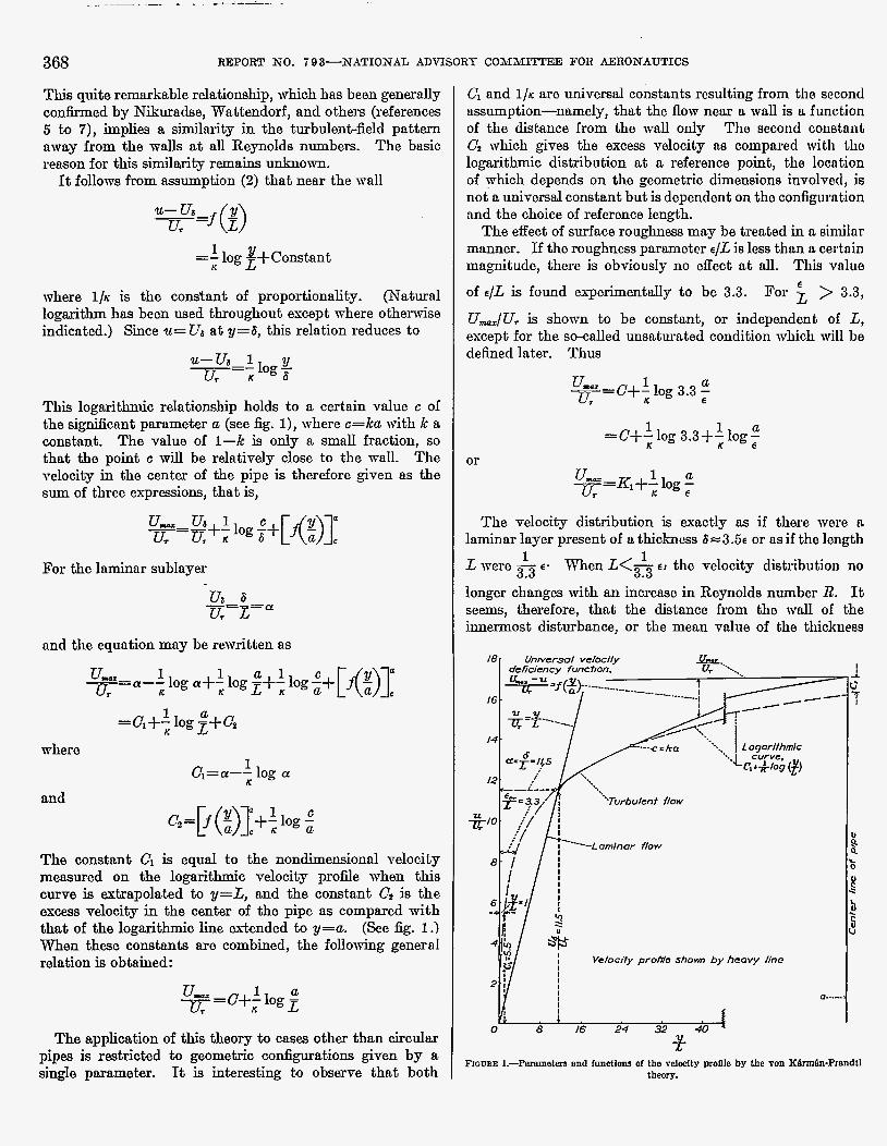
This logarithmic relationship holds to a certain value c of the signi6cnnt p a m e t e r a (see fig. l), where c=ka vith k a constant. The value of 1-k is only a small fraction, so that the point c will be relatively close to the mall. The velocity in the center of the pipe is therefore given as the sum of three exprssions, that is,
For the lnminar sublayer
ua 6 u. E=a --
and the equntion mny be rewritten as
l a =a+; log E+"* whero
and
1 C,=a-- log a K
c;= f I! +-log; c (a)]: : The const.ant C1 is equal to the nondimensiond velocity measured on the logarithmic velocity profile when this curve is extrapolated to y=L, and the constant Cr is the e x w velocity in the center of the pipe 8s compared with that of the logarithmic line extended to y=a. (See fig. 1 .I When these constants axe combined, the following general relation is obtained:
qy ="+; l a log E
The application of this theory to caw other than circular pipes is restricted to geometric configurations given by a single parameter. It is interesting to observe that both
Cl and 1 / ~ are universal constants resulting from tho second assumption-namely, that the flow near a wall is a function of the distance from the w d only The second constant C; which gives the excess velocity na compsred wit11 tho logarithmic distribution at a reference point, the locntion of yhich depends on the geometric dimensions involved, is not a universal constant but is dependent on the configurntion nnd the choice of reference length.
The effect of surface roughness may be treated in a similnr manner. If the roughness parameter e/L js less than a cerhin ma-dtude, there is obviously no effect a t d. This vnlue
of a/L is found experimentally to be 3.3. > 3.3,
U&Ur is shorn to be constant, or independont of L, except for the so-called unsaturated condition which will be dehed later. Thus
For
1 a -- u- "+,log 3.3 ; UT -
or
The velocity distribution is .exactly ns if there were n laminar layer present of a thickness 6 c 3 . 5 ~ or ns if the length
1 1 L were - E- When L < s E > the velocity dishibution no 3.3 longer changes with an increase in Reynolds number R. It seems, therefore, that the distance from the wall of the innermost disturbance, or the mean value of the thickness
Q..."
DRAG O F REVOLVING DISKS, CYLINDERS, A N D S!CREAMLIAW RODS AT HIGH SPEEDS 369
of the laminnr layer, is of the order of three to four times the height of the irrcgularitim or the grain size E . This fact is not inconsistent with the physical interpretntion.
The quantity U&U7 is shown to equal dg. Further,
and, therefore,
where R is referred to the mmimum velocity and is equal to Umap.Iu. The equation
may thus be written
E= C+: log R fi or
where 1 c-- R log1&
Ca = \I3
By the similarity hypothesis, the m a n velocity in n pipe difTers from the maximum value by a constant, or
where 0, is the mean value of the velocity. Prandtl gives 4.07 for the valua of K2. Note further thnt the product R G remains the same whether R and CD refer to the mean or the maximum value of the velocity; therefore,
(See reference 3, p. 142.)
and, finally, with R and CD referring to the mean velocity,
where
With 0=5.5 and ~=0.4,
P, ~ 0 . 4
This value is not accurately established, as the various authors seem to differ.
DRAG OF FLAT PLATES
In order to obtnin the drag formula for flat plates, n calculation similar to the von KBrmh-Prandtl treatment for pipes may be performed. The velocity deficiency Auk given by the relation
where UTm is a mean value between 0 and 2, the distance along the plate. The missing momentum may be mitten as
or
where U is the strenm velocity and 61 is a significant length giving the thickness of the boundary layer. Rewritten, this equation becomes
or, by virtue of the similarity law,
Since the momentum is given directly as
the following identity is obtained:
or
Using the logarithmic deficiency relation gives for C5 the value I/., or 2.5, and for c6/c5 the value 2 / ~ , or 5; thus
370 REPORT NO. 703-NATIONAL ADVISORY COMMITTEE FOR AERONAUTICS
By use of the von KhBn-Prandtl treatment, the stream velocity is obtained in essentially the same form as for pipes. With small adjustments, therefore,
By use of the expression for &/x, the following equation is obtained:
R z C D m -K4+4.07 log,, 1 - 3 . 5 4 G
LOCAL VALUES OF DRAG COEFFICENT FOR FLAT PLATE9
It may be noted that a relation for the local drag co&cient on a flat plate may be found in a fashion similar to that used later for a disk. Consider a plate of unit width; for the full length I,
With the subscripts m and z referring to mean and local values, respectively, for the length x,
or
Therefore
where
BOUNDARY RELATION FOR REVOLVING DISK8
The moment coef6cient is defined as
The moment may also be mitten
M = 2 p (24urup. dy
where u, is the variable radial velocity and ut is the tnngen- tial velocity, from which
or
!!!=constant a
The drag formula then reads
A similar result was obtained by Goldstein in referonce 4. .
TESTS A N D RESULTS
Tests on disks, cylinders, and streamhe rods wore con- ducted to determine drag or moment coefficionts. For tho cylinder the two coefficients are equivalent; for tho disk and the rod it is more convenient to employ tho momont coo5- cient, which can be msasured directly. In order to oxtond the range of Mach number, several tests WOTC conducted with Freon 12 or Freon 113 as the medium. Tho test results obtained are of technical interest bccause mmo of the data, particularly for the high Mach numbor rango, were obtained for the first time. It may be pointed out that many of the earlier tests on revolving disks and, in particular, on revolving cylinders more conductod on n rather amah scale and in a limited range of Roynolds num- ber. It may be notrd that a considerable mngo of Roynolds number is generally needed in order to confirm with s u 5 - cient reliability a particular theoretical formula. For instance, it may be impossible to obtain a meosurable difference between logarithmic or power formulas if a short range of Reynolds number is available. This mattor of distinguishing between the various types of formulas is of theoretical interest.
EXPBRIMENTB ON REVOLVING DISKS
The moment coefficient is defined as
M Cx=, 7Pw’a6
This definition corresponds to the one for laminar flow on a revolving disk given by von K6rmfin in referenco 1 as:
Cdd = alR-In where
CLULz E=- 0
DRAG OF REVOLVING DISKS, CYLINDEEtS, AND STREAMLINE RODS AT H I G H SPEEDS
-f. 0
%2,
3 4
371
won Kdrm@'s lamnor-ffow formula, o 24-1k-diam. &sh h ah '\,/ . -CM-987R- -b l Z - a - d a m . dish in cvF .
I x .%all akks on synchronous motor 0 A r jet on smooth 24-in.-dom d&h 0 6Omesh scnd on 24-1n.-dam. &k \ x .
X
\ I I
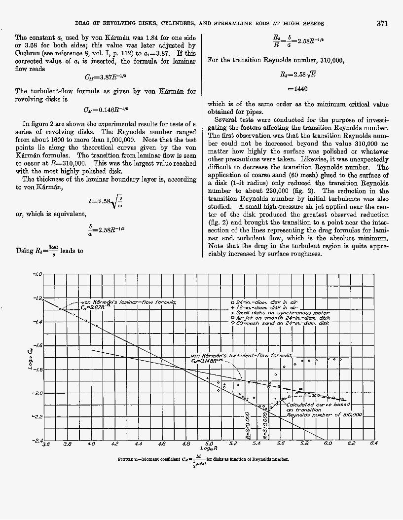
The constant a used by von K:&rm8n was 1.84 for one side or 3.68 for both sides; this value was later adjusted by Cochran (see reference 8, vol. I, p. 112) to ul=3.87. I f this corrected value OI al is inserted, the formula for laminar flow rends
Ck= 3.87R-'"
The turbulenbflow formula as given by von K:&rm&n for revolving disks is
ck=0.146R-'/6
In figure 2 are shorn the experimental results for tests of a series of revolving disks. The' Reynolds number ranged from about 1600 to more than 1,000,000. Note that the test points lie along the theoretical curves given by the von KSrm&n formulas. The transition from laminar flow is seen to occur a t R=310,000. This was the lmgest value reached with the most highly polished disk.
The thickness of the laminar boundary layer is, according to von K&rm&n,
6=2.58 - 8 or, which is equivalent,
6 -=2.58R-'P U
b w a Using Ra=- leads to U
For the transition Reynolds number, 310,000,
= 1440
which is of the same order as the minimum critical vdue obtained for pipes.
Several tests were conducted for the purpose of investi- gating the factors affecting the transition Reynolds number. The h t observation was that the transition Reynolds num- ber could not be increased beyond the value 310,000 no matter how highly the surface was poliahed or whatever othar precautions were taken. Likewise, it was unexpectedly difEcult to decrease the transition Reynolds number. The application of c o m e sand (60 mesh) glued to the surface of a disk (1-ft radius) only reduced the transition Reynolds number to about 220,000 (fig. 2). The reduction in the transition Reynolds number by initial turbulence was also studied. A small high-pressure air jet applied near the cen- ter of the disk produced the greatest observed reduction (k. 2) and brought the transition to a point near the inter- section of the lines representing the drag formulas for lami- nar and. turbulent flow, which is the absolute minimum. Note that the drag in the turbulent region is quite appre- ciably increased by surface roughness.
372 REPORT NO. 7 9 3-NATIONAL ADVISORS COMMITI'EE FOR AERONAUTICS
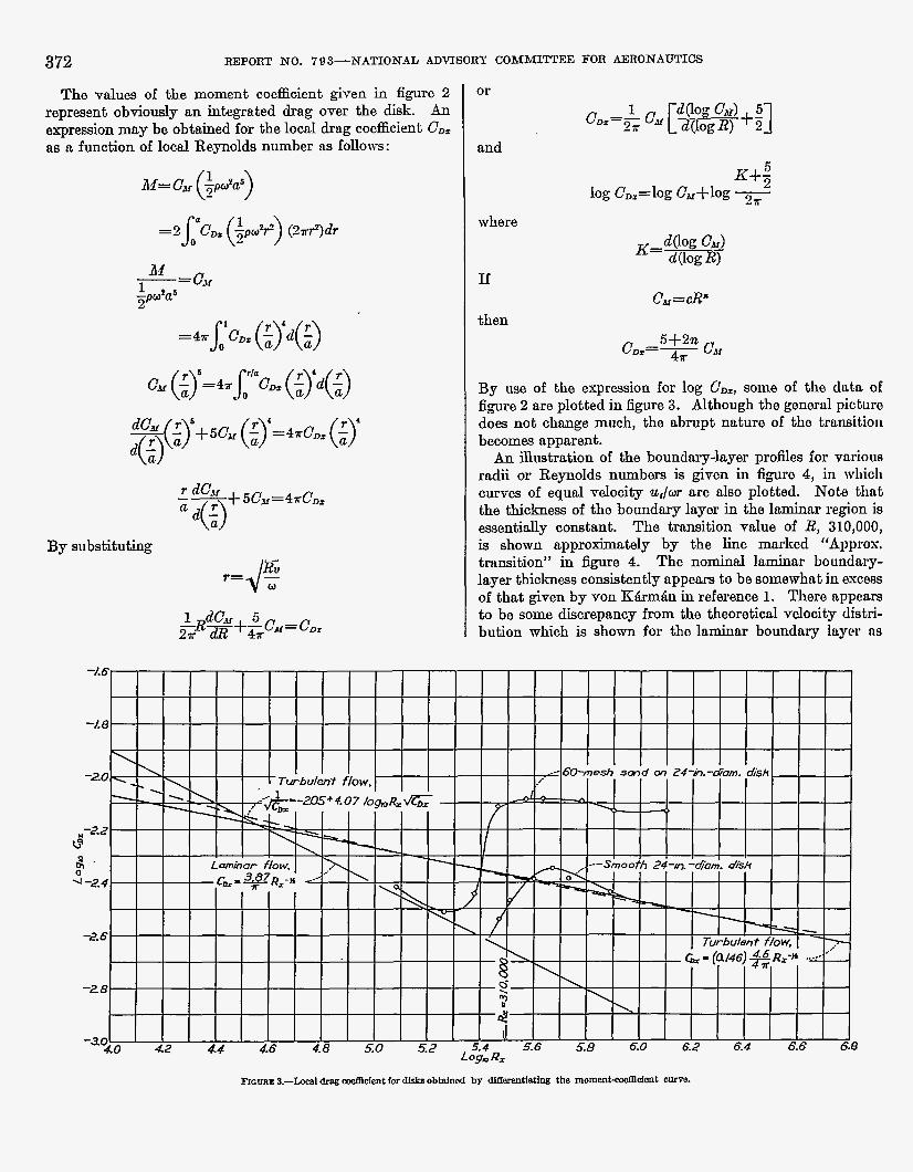
The values of the moment coefficient given in figure 2 repreaent obviously an integrated drag over the disk. An expression m y be obtained for the locnl drag coefficient C D ,
as a function of local Reynolds number 8s follows:
By substituting
or
and
where
If
then C,=*
By we of the expression for log C'D,, some of the data of €igure 2 are plotted in figure 3. Although the general picture does not change much, the abrupt nature of the transition becomes apparent. An illustration of the boundary-layer profiles for various
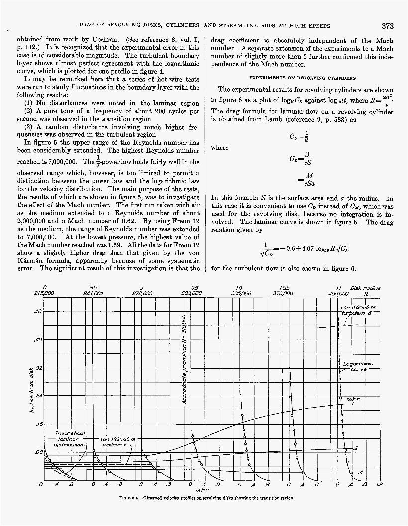
rndii or Reynolds numbers is given in figure 4 , in which curves of equnl velocity uJ0r are also plotted. Note that the thickness of the boundnry layer in the laminnr region is essentially constant. The transition value of R, 310,000, is shown approximately by the line marked "Approx. transition" in figure 4. The nominal laminar boundav- layer thickness consistently apponrs to be somewhat in excw of that given by von K4rmfin in reference 1. There appears to be some discrepancy from the theoretical velocity distri- bution which is shown for the laminar boundary layer ns
hcrrar. 3.--Loeal drag owfedent for d k b obfained by dlf[erentlatlng the momentcoef8dent carve.
DRAG OF REVOLVING DISKS, CYLINDERS,
obtained from work by Cochran. (See reference 8, vol. I, p. 112.) It is recognized that the experimental error in this cnse is of considerable magnitude. The turbulent boundary layer shows h o s t perfcct agreement with the logarithmic curve, which is plotted for one profle in figure 4.
It may be remarked here that a series of hot-wire tests were run to study fluctuations in the boundmy layer with the following results :
(1) No disturbnnces were noted in the laminar region (2) A pure tone of a frequency of about 200 cycles per
second was observed in the trmition region (3) A random disturbance involving much higher fre-
quencies wns observed in the turbulent region In figure 6 the upper range of the Reynolds number has
been considerably extended. The highest Reynolds number 1
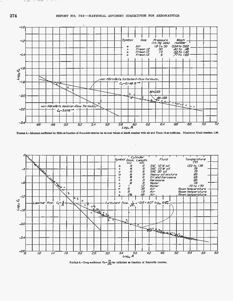
rcnched is 7,000,000. The 7-powerlaw holds fairly well in the observed range which, however, is b o limited to permit a distinction betweon the power law and the logarithmic law for the velocity distribution. The main purpose of the teats, the results of which are shorn in figure 6 , was to investigate the effect of the Mach number. The b t run taken with air ns the medium extended to a Reynolds number of about 2,000,000 and a Mach number of 0.62. By using Freon 12 ns the medium, the range of Reynolds number was extended to 7,000,000. At the lowest pressure, the highest value of the Mach number reached wns 1.69- All the data for Freon 12 shorn a slightly higher drag than that given by the von R&rmfin formula, apparently because of some systematic error, The. significnnt result of this investigation is that the
8 85 9 95 303, a00
373
drag coefficient is absolutely independent of the Maoh number. A separate extension of the experiments to a Mach number of slightly more than 2 further conhned this inde- pendence of the iMnch number.
VD STREAMLIATE RODS AT HIGH SPEEDS
EXPERIMENTS ON REVOLVING CYLTNDERS
The experimental results for revolving cylinders are shown in figure 6 as a plot of log&D against log&, where R=Y- w a g
The drag formula for laminar flow on a revolving cylinder is obtained from Lamb (reference 9, p. 588) as
where
In this formula S is the surface area and a the radius. In this w e it is convenient to use C D instead of Ck, which was used for the revolving disk, because no integration is in- volved. The laminar curve is shown in figure 6. The drag relation given by
0.64-4.07 log,, R a , ,m- for the turbulent flow is also s h o r n in figure 6.
I O /a5 f I Dish radius 3 7 0 . m
t4br
h o n a ~ L-ObServed valoalty pro& on revolving d l n b showing the tranrltlon d o n .
- ~
374 REPORT N O . 7 9 3 - N A T I O N A L ADVISORY COMMITTEE FOR AEXONAUTICS
R h a w s &-Moment &dent for disks as function d Reynolds number fur saveial va3.w of Maah number with and Freon l2 as medInma. Marlmum hIaoh number, LE@.
DRAG O F ELElVOLVING DISES, CYLINDEIRS, AND 8- RODS AT HIGH SPEEDS 375
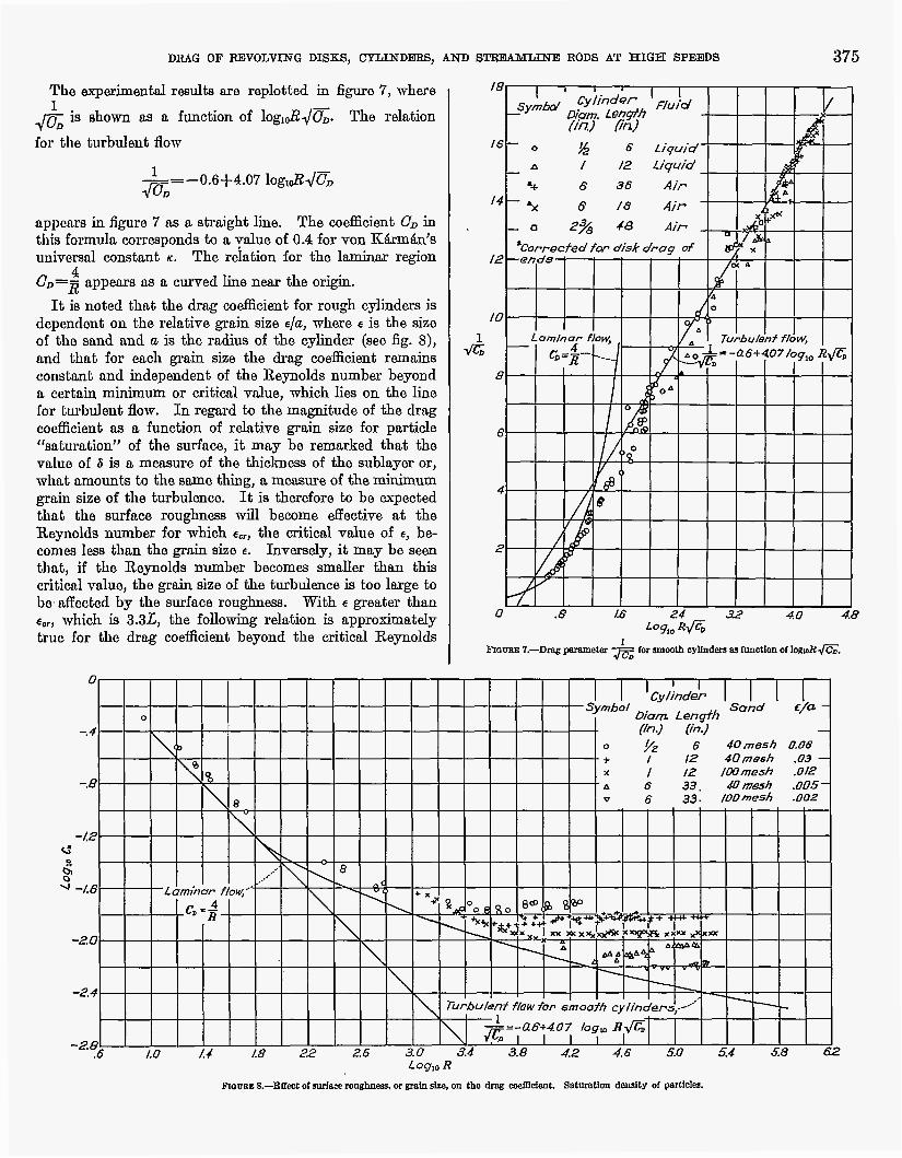
The experimental results are replotted in figure 7, where 1 fi is shorn na a function of logl&/%. The relation
for the turbulent flow
--0.6+4.07 log,&dG a- appcars in figuro 7 as a straight line. The coefficient C, in this formula corresponds to a value of 0.4 for von E;&rm&n’s universal constant K . The relation for the laminar region
U D = ~ appears as a curved line near the origin.
I t is noted that the drag coacient for rough cylinders is dependent on tho relative grain size ala, where e is the size of tho sand and a is the radius of the cylinder (see fig. S), and that for mch grain size the drag codcient remains constant and independent of the Reynolds number beyond II certain minimum or critical d u e , which lies on the line for turbulent flow. In regard to the magnitude of the drag coefficient as a function of relative grain size for particle “saturation” of the surface, it may be remarked that the valuo of 6 is a memure of the thickness of the sublayer or, what amounts to the same thing, a measur0 of the minimum grain size of the turbulence. It is therefore to be expected that the surfacs roughness will become &ective at the Reynolds number for which e,, the critical value of e, be- comes less than the grain size E. Inversely, it may be seen that, if tho Reynolds number becomes smaller than this c r i t i d value, the grain size of the turbulence is too large to be, affected by the surface roughness. With e greater than
which is 3.3L, the following relation is approximately true for the drag coefficient beyond the critical Reynolds
4
?
376 REPORT NO. 7 9 3-NATIONAL ADVISORY COMhLITTEE FOR AERONAUTICS
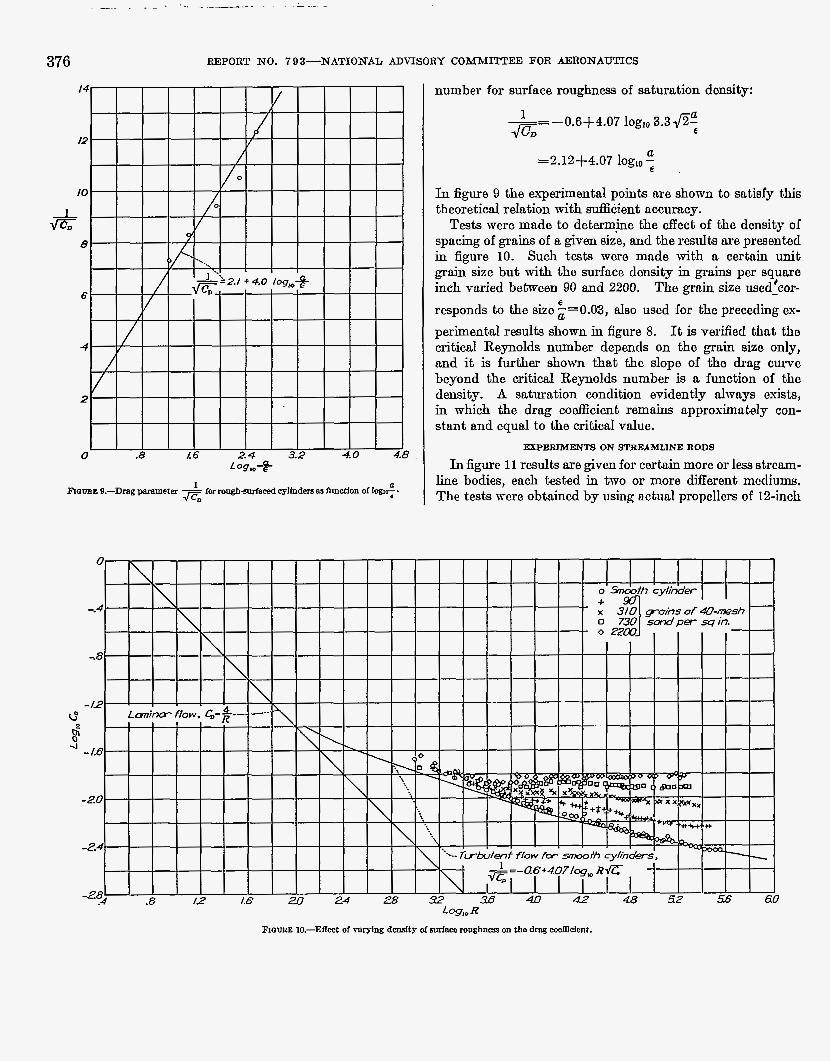
number for surface roughness of saturation density:
1 ~ = - 0 . 6 + 4 . 0 7 log,, 3.3.JZa €
=2.12+4.07 log,, 7 U
In figure 9 the e q e r i m e n t a l points me shown to satisfy this theoretical relation with suf6cient accuracy. Tests mere made to determjne the &ect of the density of
spacing of g r a d of a given size, and the results nre presented in figure 10. Such tests mere mnde with a certain unit grain size but with tho surface density in grains per squaro inch varied between 90 and 2200. The grain size used:cor- responds to the size ;=0.03, also used for the preceding os- perimenhl results shown in figure 8. It is verified that tho critical Reynolds number depends on the grnin size only, and it is further shorn that the slope of the drag curvo beyond the critical Reynolds number is a function of the density. A saturation condition evidently always exists, in which the drag co&cient remains approximately con- stant and equal to the critical value.
E
EXPERTMENT8 ON STREAMLINE RODS
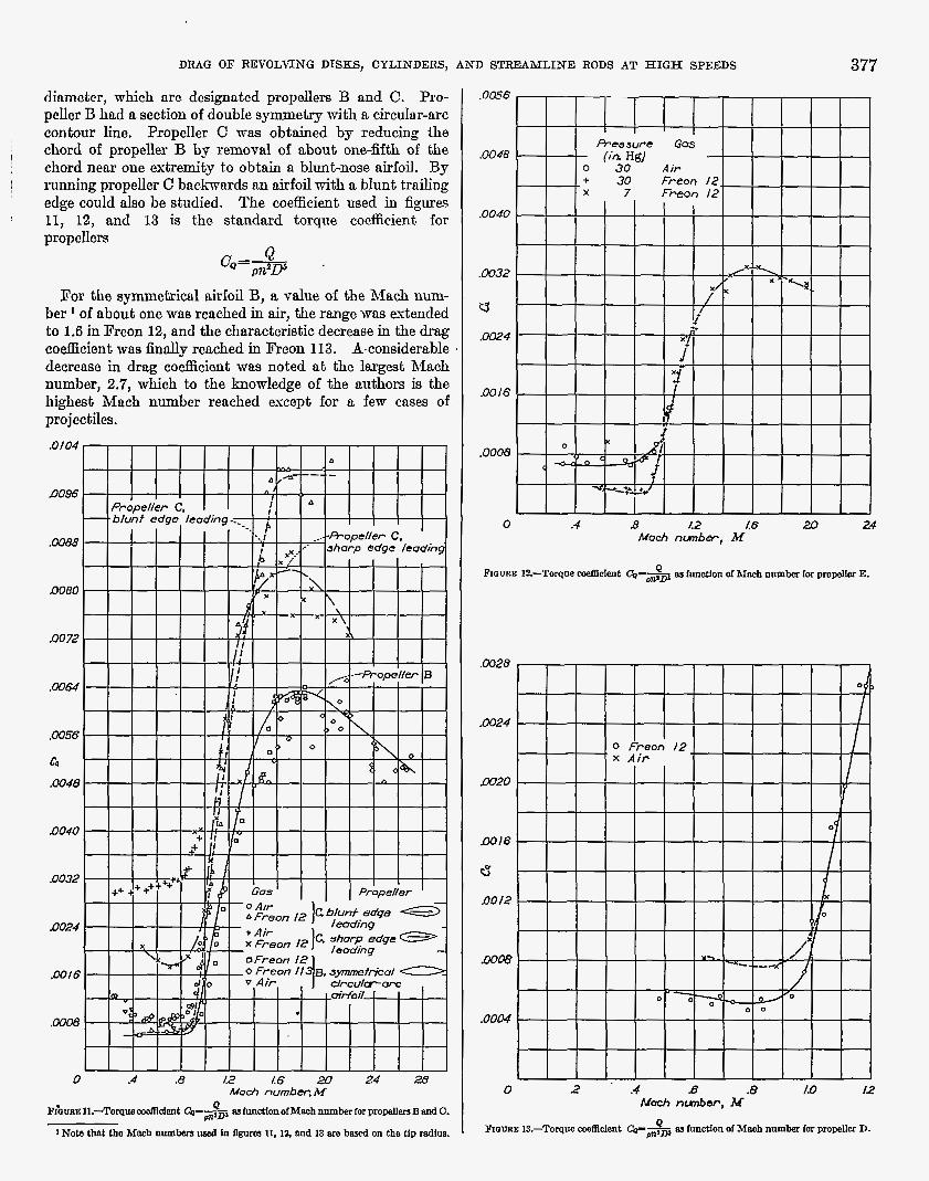
In figure 11 results are given for certain more or less stream- line bodies, ench tested in two or more different mediums. The tests were obtained by using actual propellers of 12-inch
DRAG O F REVOLVING DISKS, CYLINDERS, AND STFiEAMLINE RODS AT H I G H SPEEDS
diameter, which are dcsignated propellers B and C. Pro- peller 13 had a section of double symmetry with a circular-arc contour line. Propeller C mas obtained by reducing the chord of propeller B by removal of about one-fifth of the chord near one extremity to obtain a blunt-nose airfoil. By running propeller C backwards rm airfoil with a blunt trailing edge could d s o be studied. The coefficient used in fi,wes 11, 12, and 13 is t,ho standard torque coefficient. for propellers
c"=m Q .
For the symmetrical airfoil B, a value of the Mach num- ber of about one wns reached in air, the range mas extended to 1.6 in Freon 12, and the characteristic decrease in the drag coefficient mas finally reached in Freon 113. A,considerable decrease in drag co&ciont wna noted a t the largest Mach number, 2.7, which to the knowledge of the authors is the highest Mach number reached exept for a few cnses of pro j ectilcs.
377
0 .4 B 12 l.6 Mach nunber, M
Fraws 12-Torqae &dent CQ& BS fmotlon of Na& number for propellar E.
0 2 .4 s .8 ID I2 Mach nunbar, M
prow^ 13.-Torqoe co%fllcIent CpsP BS function of Maoh number for propeUer D.
378 REPORT NO. 7 9 8-NATIONAL ADVISORY COMMITTEE FOR AERONAUTICS
The blunt-nose airfoil section C showed approximately the same low-speed resistance as the symmetrical sharp-nose section B but had a maximum torque coacient very much in excess of that of section B. The test extended only to near the peak of the torque curve with Freon 12 as the medium. By reversing the direction of motion of propeller C to obtain a blunt rear, the expected large increase in drag a t low Mach numbers was observed. The appreciable difference in Reynolds number for air and Freon 12 is apparent from the difference in drag co&cients in the range below a Mach number of unitg. For higher Mach numbers, tho drag co&cient of the section with the blunt rear lies betmeen the drag coefficients of the doubly streamline section nnd the blunt-nose type; the streamline leading edge is approximately tmice as effective as the streamline trailing edge, a result in general agreement with earlier observations. It should be noted, however, that the lowest drag is obtained with both lading and trailing edges streamlined.
The effect of the Reynolds number is &o shown in @e 12, which gives the results of tests to study how the scale effect is superimposed on the Mach number effect. It should bo noted rtgain that the Reynolds number effect appecus only for a Mach number below unity. A wide variation in the Reynolds number shows no consistent measurable effect on tho h g for a Mach number greater than unity. Similar data for a small angle of attack, instead of zero angle of attack as used in the preceding discussion, were used in one case, for which results are given in figure 13.
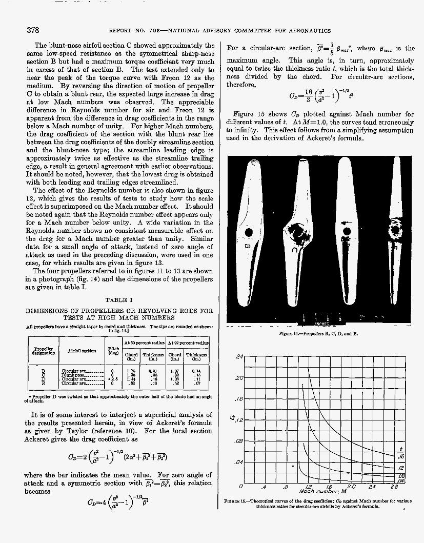
The four propellers referred to in figures 11 to 13 me shown in photograph (fig. 14) and the dimensions of the propellers are given in table I.
TABLE I
DIMENSIONS OF PROPELLERS OR REVOLVING RODS FOR TESTS AT HIGH MACH NUMBERS
fn %. 14.1 All pro&lemhve a straight taper In chard and Thew are romded as a h m
I I
I I
o[;tbe D m twisted m that appmdmatdy the ontar half of the blade had an angle
It is of some interest to interject a supeficial analysis of the results prssented herein, in view of Ackeret's formula as given by Taylor (reference 10). For the local section Ackeret gives the drag coefEcient as
where the bar indicates the mean value. For zero angle of attack and a symmetric section mith g=x this relation becomes
1 3
For a circular-arc section, p=- prn.2, whom pmo+ IS tlic
maximum angle. This angle is, in turn, approrcimntoly equal to twice the thichess ratio t , which is tho total thick- ness divided by the chord. For circular-arc scciions, therefore,
Figure 15 shows CD plotted against h4acli numbor for different values of t. At M=1.0, the curves tond erronoously to idnifiy. This effect follows from a simplifying assumption used in tho derivation of Ackeret's formuln.
. - . -- - - . - - - __ piSare l4.--prO@ler8 B, 0, D, and E.
I
F I Q ~ E K-Theoretical m e s of the drag d o l a a t CD Ma& numbor for wbus thlcknfm intlos for dmnlar-am alrIoIls by Ackieret's formula.
D U G O F REVOLVING DISKS, CYLINDERS, AND STEUUMLINE RODS AT H I G H SPEEDS 379
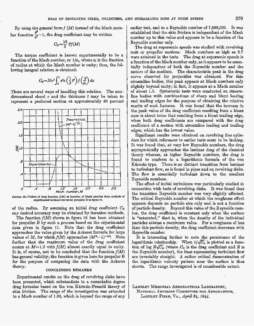
By using the generd formf (&I) instead of the Mach num- tp ber function 3 - 1 , the drag coefficient may be written
c D = Y e(lM)
The torque coefficient is h o r n experimentally to be a function of the Mach number, or l/q, where z1 is the fraction of radius a t which the Mach number is unity; thus, the fol- lowing integral relation is obtained:
There are several ways of handling this relation. The non- dimemional chord c and the thickness t may be taken to roprcaent a preferred section at approximately 80 percent
M a c h m b e r . M Flame lB.-Velue of ding function I(M) an innotion of Mach number from anal& of
arpUimantal moment arm for propeller B In flgme 11.
of tho radius. By assuming an initial drag co&cient C D any desired accuracy may be obtained by iteration methods.
The functionf(M) shown in figure 16 has been obtained for propeller B by such a process based on the experimental data given in figure 11. Note that the drag coefficient approaches the vdue given by the Ackeret formula for large values of M, for whichf(M) approaches (M9-l)-1’*. Note further that the maximum value of the drag coefficient occm at M=1.2 withf(M) almost exactly equal to unity. It is, of come, not to be concluded that the functionf(d4) has general validity; the function is given here for propeller B for the purpose of comparing the data with the Ackeret theory.
CONCLUDING REMARKS
Experimental results on the drag of revolving disks have been presented, which substantiate to a remarkable degree drag formulas baed on the von Ktkmh-Prandtl theory of skin friction. The range of the investigation wm extended to a Mach number of 1.69, which is beyond the range of any
sarlier test, and to a Reynolds number of 7,000,000. It was established that the akin friction is independent of the Mach number up to this value and appears to be a function of the Reynolds number only.
The drag at supmonic speeds was studied with revolving rods or propeller sections. Mach numbers as high as 2.7 were attained in the teats. The drsg at supersonic speeds is a function of the Mach number only, as it appears to be essen- tially independent of both the Reynolds number and the nature of the medium. The characteristic peak in the drag curve observed for projectiles was obtnined. For thin ~trsamline bodies, this peak appears at Mach numbers only slightly beyond unity; in fact, it appears at 8 Mach number of about 1.2. Systematic testa were conducted on strenm- line bodies with combinations of sharp and blunt leading and trailing edges for the purpose of obtaining the relative merits of such features. It was found that the increase in the peak value of the drag coacient resulting from a blunt nose is about twice that resulting from a blunt trailing edge, when both drag coefficients are compared with the drag coefficient of a section with streamline leading and trailing edges, which has the lowest value.
Si@cant results mere obtained on revolving free cylin- ders for which references to earlier tests seem to be lacking. It was found that, at very low Reynolds numbers, the h m
asymptotically approaches the laminaz drag of the classid theory whereas, at higher Reynolds numbers, the drag is found to conform to a logarithmic formula of the von K h 8 S type. There is no distinct transition from laminar to turbulent flow, as is found in pipes and on revolving disks. The flow is essentially turbulent down to the smallest Reynolds numbers.
The effect of initial turbulence was particularly studied in connection with tests of revolving disks. It was found that the transition Reynolds number was very slightly affected. The critical Reynolds number at which the roughness effect appears depends on particle size only and is not a function of particle density. Beyond this value of the Reynolds num- ber, the drag coeflicient is constant only when the surface is “saturated,” that is, when the density of the individual particles attains a mmimum value. For a roughness of less than this particle density, the drag coefficient decreases with Reynolds number.
It is interesting further to note the persistence of the logarithmic relationship. When l/G is plotted as a func- tion of log B G (where CD is the drag co&cient and R 19 the Reynolds number), the linea representing turbulent flow are invariably straight. A rather critical demonstration of the logarithmic vdocity pattern near the surface is thus shown. The range investigated is of considerable extent.
LANQLEY M ~ n r o m ~ ~ R O N A U T I C A L LABOEATOEY, NATIONAL ADVISORY C O ~ N E FOR ADRONAUTICS,
LANGLEY PIELD, VA., April 24,19&.
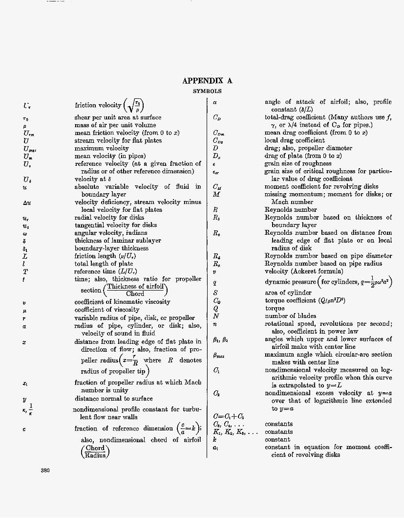
APPENDIX A SYMBOLS
I -r TO
P U, U
Ua U
AU
'u.1
ut
6 61 L 1 T f
0
V
Ir r a
2
Y 1
' J
C
($9 friction velocity
shear per unit area at-surface mass of air per unit volume mean fi-iction velocity (from 0 to 2) stream velocity for flat plates maximum velocity mean velocity (in pipes) reference velocity (at a given fraction of radius or of other reference dimension)
velocity at 6 absolute variablc velocity of fluid in
velocity ddciency, stream velocity minus
radial velocity for disks tangential velocity for dish angular velocity, Fadians thickness of laminar sublayer boundary-layer thickness friction length (u/U,) total length of plate reference time (L/U,) time: also. thickness ratio for vroveller
boundary layer
local velocity for flat plates
- A
Thickness of airfoil section ( Chord
coef6cient of h e m a t i c viscosity co efficient of viscosity variable radius of pipe, disk, or propeller radius of pipe, cylinder, or disk; also,
velocity of sound in fluid distance from leading edge of flat plate in
direction of flow; also, fraction of pro- peller radius X=B where R denotes radius of propeller tip
fraction of propeller radius at which Mach number is unity
distance normal to surface nondimensional prof& constant for turbu-
fraction of reference dimension -=k J
also, nondimensional chord of airfoil
) ( r
lent flow near walls
(: >-
81, a 8-
Cl
G
angle of attack of airfoil; also, profilo
tot,al-d.rag coefficient (Many authors us0 f,
mean drag coefficient (from 0 to 2) local drag coefficient drag; also, propeller diameter drag of plate (from 0 to 2)
grain size of roughness grain size of critical rougllnoss for particu-
moment coefficient for revolving disks missing momentum; momont for disks; or
iMach number Reynolds number Reynolds number based on thickness of
boundary layer Reynolds number baaed on distnnco from
leading edge of flat plate or on local radius of disk
Reynolds number based on pipe diamotor Reynolds number based on pipe radius velocity (Ackeret formula) dynamic pressure for cylinders, q=spw2a2)
area of cylinder torque coefficient (Q/pn2Ds) torque number of blades rotational speed, revolutions per second ;
also, coefficient in power law angles which upper and lower surfaces of
airfoil make with center line maximum angle which circular-arc soction
makes with center line nondimensional velocity measured on log-
arithmic velocity profle when this curve is extrapolated to y=L
nondimemiond excess velocity at y=a over thnt of logarithmic line extonded to y=a
constant (6/L)
7, or X/4 instead of CD for pipes.)
lar value of drng coefficient
1 (
constants constants constant constant in equation for moment coeffi-
cient of revolving disks
380
APPENDIX B NUMERICAL VALUES OF POWER REQUIREMENTS FOR REVOLVING DISKS AND CYLINDERS
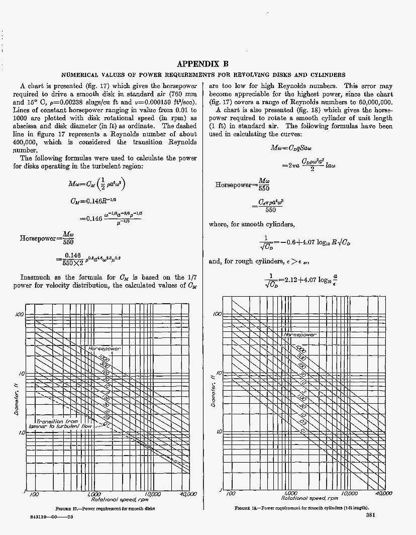
A chnrt is presented (fig. 17) which gives the horsepower required to drive a smooth disk in standard air (760 mm and 16' C, p=0.00238 slugs/cu f t and u=0.000159 fi?/sec). Lines of constant horsepower ranging in value from 0.01 to 1000 are plotted with disk rotational speed (in rpm) as abscissa and disk diameter (in ft) as ordinate. T h e dashed line in figure 17 represents a Reynolds number of about 400,000, which is considered the transition Reynolds number.
The following formulas were used to calculate the power for disks operating in the turbulent region:
U-llSa-4/6p-1/5
=0.146 / p / s
Horsepower=m MU
0.146 ,- os 16 e8 0.2 650x2 ' a
Innsmuch na the formula for Cu is based on the 1/7 power for velocitg distribution, the calculated values of C,
are too low for high Reynolds numbers. This error may become appreciable for the lllghest power, since the chart (fig. 17) covers a range of Remolds numbers t o 60,000,000.
A chart is also presented (e. 18) which gives the horse- power required to rotate a smooth cylinder of unit length (1 f t ) in standard air. The following formulas have been used in calculating the curves:
Mo=C&W
Hompow0r=- MU 550
C.Upa4d =- 550
where, for smooth cylinders,
E=- 0.64-4.07 log,, RJC,
and, for rough cylinders, E > E -,
a -- -2.12-l-4.07 log,,; 4%
Rofofiwml speed r p m
prom Ig-Powa reqalrement for m t h oyllndars ( 1 4 length). 381
APPENDIX c COLLECTED SHIN-FRICTION FORMULAS
F%AT PLATES (ONE SIDE) SYMBOLS
The following symbols are used iu the formulas for flat plates collected herein:
OD total drag coefEcient 00, local drag coefEcient at point z
2 distnnce from leading edge of flat plate in direction of
1 length of flat plate in direction of flow R Reynolds number bnaed on 1 R, Reynolds number based on z
flow
LAMINAR FLOW
The formula for total drag coefticient
CD= 1.32812-'"
is bnsed on the simplified hydrodynamic equations developed by Prandtl in 1904. (See reference 2, p. 2.) The constant, which wns calculated by Blasius in 1908 as 1.327, was cal- culated by T8pfer in 1912 as 1.328. (See reference 3, p. 89.) The formula for local drag coacient is
UD,=0.664Rz-"
Von K&rm&n, Schoenherr, and others have indicated that, if the total drag coe5icient is
UD=Constant R"
bho locnl drag codcient is given as
QDx= (n+ 1) CD
This relation is derived in the section entitled "Local Values of Drag Codcient for Flat Plates" in this paper. All for- mulns given in this appendix for the local drag on flat plates aro in conformity with this derivation.
TURBULENT F L O W 4 M O O T H SURFACE
The formulna
mid
wore h t calculated by von K h h in 1920. (See references 1
1 and 2.) Bnsed on results from pipes and on the ?-power law for velocity distribution, they are consequently valid in, the Iowcr Reynolds number range, R<10,00O,000.
382
Some writers use the following formulas of the same type, which are fairly accurate to a Reynolds number of 500,000,000:
CD = o.030R-1n
Of more general validity are the so-called logarithmic drag formulas of the type
~ - = 4 . 1 5 1 logl$cD CD
The form of this relation was determined by von K h h with constants adjusted to conform with data by Schoenherr andothers. (See reference 2, p. 12.) In the present paper a different form has been developed, which is in somewhat stricter theoretical conformity with the physical relations involved :
-- 1 ROD G-4*07 log,, 1-3.54mD
Prandtl has developed an explicit expression which gives essentially the m e results as the logarithmic formulas. It is
(See reference 3, p. 163.) The local drag coefficient has also been given by von K&m&n in a logarithmic form with the conshta adjusted to fit the experiments of Kemp, which included measurements on small movable plates inserted on a long pontoon. This formula is
-- -1.7-l-4.15 logl&C, G (See reference 2, p. 12.)
TURBULENT FLOW-ROUGH SURFACE
Schlichting (see reference 8, p. 382) gives the two following formulas for the total and the local drag coefticients for rough flat platw, respectively:
-2 6 CD=( 1.89+1.62 log,, 2)
E
cD,=( 2.87 + 1.58 log,, 2)-y5 €
Von K h h (reference 2, p. 18) gives for the local drag coefficient for rough surfaces a formula of the logarithmic type
-- 1 -5.84-4.15 log,,: , I C K z
DRAG O F REVOLVING DISKS, CYLINDERS, A N D STREbMLINE BODS A T H I G H SPEEDS 383 PIPES
SYMBOL8
The symbol Rd used in this section refers to the Reynolds number based on the pipe diameter and the mean flow velocity, and the symbol R, refers to the Reynolds number bnsed on pipe radius. Some writers use f or y instead of OD, used heroin, m d others ~ 8 8 X where X=4cD.
LAMINAR FLOW
For laminar flow in pipes the formula for drag coefficient is
16 OD‘K
This formula is attributed to Poiseuille and Wiedeman. (See reference 3, p. 38, and reference 8, p. 298.)
TURBULENT FLOW-SMOOTH SUBFACE
Tho formula for drag coefficient for turbulent flow in smooth pipes is
This formula is based on the experimental workof Blasius (seo reference 3, p. 136), for which the Reynolds number range was rather limited. Later work by Niliiadm (ref- erence 6 ) extended the range of Reynolds number to a much higher vdue. The follo- formula of the type devnloped by von K:&rm&n fits the data bettar:
~ D = O . O ~ ~ R ~ - - ” ‘
(Seo reference 8, p. 338.) In the present paper a formula of this typo with dif€erent constantv is developed:
TURBULENT FLOW-ROUGH SURFACE
For turbulent flow in rough pipes
a -- I -3.46+4.00 log,,; a Tho experimental work in deriving this formula was done by Nikurndse. (See reference 8, p. 380, and refexence 0.)
REVOLVING DISBS SYMBOLS
The following symbols are used in the formulas for revolv- ing disks: r/, moment coefficient U D , local drag coefficient at r d u s 2
R, Reynolds number at radius z ($) LAMINAR FLOW
For laminar flow Cx=3.87R-‘ ’
and
This formula for local drag coefEciont is derived froin the rela tion
For the development of this relation and for referonax, seo the section entitled “Experiments on Revolving Disk.” in this paper.
TURBULENT FLOW
For turbulent flow Cu = 0.146 E-‘.’
and om= 0.O53R,-‘Ib
The foimula for the local drag coefEcient CD, is derived from the equation for the moment coefficient Ck iu the same way as for the case of laminar flow. The lo& drag. coefficient in logarithmic form may be given as
1 7 = - 2 . 0 5 + 4 . 0 7 3 Dx log,, R,-@;
The constant -2.05 has been adjusted to fit the dnta of figure 3.
REVOLVING CYLINDERS
For laminar flow CD=B 4
For turbulent flow on smooth cylindem
0.6+4.07 log,, R d G 1
For turbulent flow on rough cylinders
a -- --2.1+4.0 log,, - 1 a €
The development of these formulas and the referencas me given in the section entitled “Experiments on Revolving Cylinders ”
384 REPORT N O . 7 93-ATATIONAL ADYISORY COMMITTEE FOR AERONAUTICS
REFERENCES
1. von Ehmhn, m: thwr laminare und turbulente Reibung. Z. f. a. hi. hl., Bd. 1, Heft 4, Aug. 1921, pp. 233-262.
2. von 'Kgrmtin, Th.: Turbulence and Skin Friction. Jour. Aero. Sci., vol. 1, no. 1, Jan. 19% pp. 1-20.
3. Prandtl, L.: The Mechanics of Viscous Fluids. Vol. III of Aerodynamic Theory, div. G, W. F. Durand, e&, Julius Springer (Berlin), 1935, pp. 34-208.
4. Goldstein, S.: On the Resistance to the Rotation of a Disc Immersed in a Fluid. Proc. Cambridge PhiL SOC., voL XXXI, pt. 11, April 1935, pp. 23%241.
6. Nikuradse, J.: Gesetzmhigkeiten der turbulenten Str6mung in glatten Rohren. Forschungsheft 356, Forachung auf dem Gebiete des Ingenieurmesens, Ausg. B, Bd. 3, Sept.-Oct. 1932.
6. Nikuradse, J.: StriSmungageaetze in rauhen Rohmn. Fomohungs- heft 361, Beilage zu Forachung auf dem Gebiete des Ingenieur- wesens, Ausg. B, Bd. 4, July-Aug. 1933.
7. Wattendorf, F. L.: A Study of the Effect of Curvature on Fully Developed Turbulent Flow. Proa. Roy. Soc. (London), sor. A, vol. 148, no. 865, Feb. 1936, pp. 566-698.
8. Fluid Motion Panel of the Aeronautical Remuoh Committao and Others: Modern Developments in Fluid Dynamics. Vole. I and 11, S. Goldstein, ed., The Clarendon Press (Oxford), 1938.
9. Lamb, Horace: Hydrodynamics. Sixth ed., Cambridgo Univ. Press, 1932.
10. Taylor, G. I.: Applications to Aeronautics of Aokoret's Theory of Aerofoils Moving at Speeds Greater Than That of Sound. R. PE M. No. 1467, British A. R. C., 1932.