REPORT GEOTECHNICAL EXPLORATION - Texas …texaslid.org/pdfs/Final Geotech Report-Northern...
56
REPORT GEOTECHNICAL EXPLORATION Northern Crossing West Southeast Corner of the Intersection of Interstate 35W & Loop 820 North Fort Worth, Texas Prepared for: Northern Crossing West Business Park, LLC c/o TIG Real Estate Services, Inc. 5050 Quorum Drive, Suite 400 Dallas, Texas 75254 & ING Clarion Partners 230 Park Avenue, 12th Floor New York, New York 10169 & Wrightwood Capital Lenders LP, its successors, assigns and affiliates Two North La Salle Street, 9th Floor Chicago, Illinois 60602 Prepared by: ATC Associates Inc. 1555 Valwood Parkway, Suite 160 Carrollton, Texas 75006 ATC Project No.: 74.27982.0001 January 5, 2007
Transcript of REPORT GEOTECHNICAL EXPLORATION - Texas …texaslid.org/pdfs/Final Geotech Report-Northern...

REPORT GEOTECHNICAL EXPLORATION
Northern Crossing West Southeast Corner of the Intersection of
Interstate 35W & Loop 820 North Fort Worth, Texas
Prepared for:
Northern Crossing West Business Park, LLC c/o TIG Real Estate Services, Inc.
5050 Quorum Drive, Suite 400 Dallas, Texas 75254
& ING Clarion Partners 230 Park Avenue, 12th Floor New York, New York 10169
& Wrightwood Capital Lenders LP,
its successors, assigns and affiliates Two North La Salle Street, 9th Floor
Chicago, Illinois 60602
Prepared by: ATC Associates Inc.
1555 Valwood Parkway, Suite 160 Carrollton, Texas 75006
ATC Project No.: 74.27982.0001 January 5, 2007

Via e-mail: [email protected] [email protected]
January 5, 2007
Ms. Allison R. McAfee TIG Real Estate Services, Inc. 5050 Quorum Drive, Suite 400 Dallas, Texas 75254 & Mr. Alex K. Mitzner ING Clarion Partners 230 Park Avenue, 12th Floor New York, New York 10169
Re: Report Preliminary Geotechnical Exploration Northern Crossing West Southeast Corner of the Intersection of Interstate 35W & Loop 820 North Fort Worth, Texas ATC Project No. 74.27982.0001
Dear Ms. McAfee & Mr. Mitzner:
ATC Associates Inc. (ATC) is pleased to present this Preliminary Geotechnical Exploration report for the proposed Northern Crossing West development situated at the southeast corner of the intersection of Interstate 35W and Loop 820 North in Fort Worth, Texas. ATC’s services were provided in general accordance with the scope of work defined in the Professional Services Agreement between ATC and TIG Real Estate Services, Inc. and in accordance with the scope of work outlined in ATC Proposal No. 74EM.2006.0223, dated November 14, 2006 and accepted by TIG on November 14, 2006.
ATC appreciates this opportunity to provide these services. Please contact us if you have any questions or require additional information.
Sincerely, ATC ASSOCIATES INC.
Sal M. Gazioglu, P.E. Principal Engineer
Joseph Schold, P.E. Principal Engineer The seal appearing on this document was authorized by Sal M. Gazioglu, P.E. 64097 on January 5, 2007.

Report of Preliminary Geotechnical Exploration January 5, 2007 Northern Crossing West, Fort Worth, Texas ATC Project No. 74.27982.0001
– i – TIG Real Estate Services, Inc. & ING Clarion Partners
TABLE OF CONTENTS Page
EXECUTIVE SUMMARY................................ ................................ ................................ ................................ iv
1.0 INTRODUCTION................................ ................................ ................................ ................................ ..1
1.1 GENERAL................................ ................................ ................................ ................................ 1 1.2 PURPOSE OF EXPLORATION................................ ................................ .............................. 1 1.3 PROJECT INFORMATION ................................ ................................ ................................ ....2 1.4 REPORT ................................ ................................ ................................ ................................ ...3
2.0 SITE AND SUBSURFACE CONDITIONS................................ ................................ ......................... 4
2.1 SITE CONDITIONS................................ ................................ ................................ ................. 4 2.2 GEOLOGY ................................ ................................ ................................ ............................... 4 2.3 SOILS........................................................................................................................................5 2.4 FIELD EXPLORATION................................ ................................ ................................ ..........6
2.4.1 GENERAL .....................................................................................................................6 2.4.2 DRILLING AND SAMPLING ...........................................................................................6
2.5 LABORATORY TESTING ................................ ................................ ................................ .....7 2.4 SUBSURFACE CONDITIONS................................ ................................ ............................... 7 2.5 GROUNDWATER CONDITIONS ................................ ................................ ......................... 8
3.0 FOUNDATION EVALUATION ..........................................................................................................9
3.1 GENERAL................................................................................................................................9 3.2 BEARING CAPACITY............................................................................................................9 3.3 FOUNDATION MOVEMENT................................................................................................ 9
3.3.1 VERTICAL MOVEMENTS..............................................................................................9 3.3.2 SETTLEMENTS............................................................................................................10 3.3.3 DIFFERENTIAL MOVEMENTS.....................................................................................10 3.3.4 FOUNDATION TYPE....................................................................................................10 3.3.5 MOISTURE CONDITIONING ........................................................................................10 3.3.6 SURFACE DRAINAGE .................................................................................................12
4.0 FOUNDATION DESIGN RECOMMENDATIONS ................................ ................................ .........13
4.1 FOUNDATION RECOMMENDATIONS................................ ................................ ............13 4.1.1 DRILLED SHAFT OR PIER FOUNDATION ....................................................................13 4.1.2 STIFFENED SLAB FOUNDATION SYSTEM ...................................................................15
4.2 FLOOR SLAB DESIGN RECOMMENDATIONS ................................ .............................. 15 4.2.1 GENERAL ...................................................................................................................15 4.2.2 SUSPENDED FLOOR SLAB..........................................................................................16 4.2.3 SLAB-ON-GRADE FLOOR SLAB................................ ................................ ................. 16
4.3 LATERAL EARTH PRESSURES.........................................................................................16 4.4 PAVEMENT DESIGN RECOMMENDATIONS ................................ ................................ 18
4.4.1 GENERAL ...................................................................................................................18 4.4.2 PAVEMENT SECTIONS................................................................................................18 4.4.3 PAVEMENT MATERIALS ............................................................................................18
4.4.4 PAVEMENT SUBGRADE ...........................................................................................................19 4.4.5 PAVEMENT CONSIDERATIONS ................................................................................................19

Report of Preliminary Geotechnical Exploration January 5, 2007 Northern Crossing West, Fort Worth, Texas ATC Project No. 74.27982.0001
– ii – TIG Real Estate Services, Inc. & ING Clarion Partners
5.0 EARTHWORK GUIDELINES ................................ ................................ ................................ ...........20
5.1 SITE GRADING AND DRAINAGE..............................................................................................20 5.2 PAVEMENT AREA SUBGRADE PREPARATION AND FILL PLACEMENT...................................20 5.3 FIELD SUPERVISION AND DENSITY TESTING.........................................................................20
6.0 BASIS FOR RECOMMENDATIONS................................ ................................ ................................ 22
FIGURES FIGURE 1 – VICINITY MAP FIGURE 2 – TOPOGRPAHIC MAP FIGURE 3 – AERIAL MAP FIGURE 4 – PLAN OF BORINGS
APPENDIX APPENDIX A – LOGS OF BORINGS

Report of Preliminary Geotechnical Exploration January 5, 2007 Northern Crossing West, Fort Worth, Texas ATC Project No. 74.27982.0001
– iii – TIG Real Estate Services, Inc. & ING Clarion Partners
RELIANCE
This report is for the use and benefit of, and may be relied upon by Northern Crossing West Business Park, LLC, TIG Real Estate Services, Inc., ING Clarion Partners, and its affiliates and Wrightwood Capital Lenders LP, its successors, assigns and affiliates, and third parties authorized in writing by TIG Real Estate Services, Inc., ING Clarion Partners and ATC, including the lender(s) in connection with a secured financing of the property, and their respective successors and assigns. Any third party agrees by accepting this report that any use or reliance on this report shall be limited by the exceptions and limitations in this report, and with the acknowledgment that actual site conditions may change with time, and that hidden conditions may exist at the property that were not discovered within the authorized scope of the assessment. Any use by or distribution of this report to third parties, without the express written consent of ATC, is at the sole risk and expense of such third party.
ATC makes no other representation to any third party except that it has used the degree of care and skill ordinarily exercised by environmental consultants in the preparation of the report and in the assembling of data and information related thereto. No other warranties are made to any third party, either expressed or implied. Unless otherwise agreed upon in writing by ATC and a third party, ATC’s liability to any third party authorized to use or rely on this report with respect to any acts or omissions shall be limited to a total maximum amount of $100,000.

Report of Preliminary Geotechnical Exploration January 5, 2007 Northern Crossing West, Fort Worth, Texas ATC Project No. 74.27982.0001
– iv – TIG Real Estate Services, Inc. & ING Clarion Partners
EXECUTIVE SUMMARY
TIG Real Estate Services, Inc. (TIG) retained ATC Associates Inc. (ATC) to perform a preliminary geotechnical exploration to develop foundation and construction related recommendations at a property referred to as “Northern Crossing West” (the site) in Fort Worth, Texas. The site consists of approximately 115 acres of undeveloped land situated at the southeast corner of the intersection of Interstate 35W and Loop 820 North in north Fort Worth, Texas. TIG is planning to acquire the property for development with several warehouse and distribution center type buildings.
The purposes of the geotechnical exploration were to (1) evaluate the subsurface conditions at the site, (2) develop geotechnical parameters for preliminary design of the foundations and (3) provide construction recommendations for the proposed buildings, appurtenant structures and site preparation and development. A brief summary of ATC’s recommendations and considerations pertinent to the design and construction of the project are presented below. This executive summary should be read in context with the entire report.
Subsurface Conditions
A field exploration was conducted at the site between November 15 and 18, 2006. Subsurface conditions beneath the site were explored by drilling twenty (20) borings throughout the site. Borings were generally advanced to a depth of approximately 25 feet below the existing ground surface for a total of approximately 470 feet of drilling. Subsurface conditions encountered beneath the paving in the borings are described as follows:
§ Top Soil: A thin veneer of top soil covers the site to a depth of approximately one foot, except in the areas where fill exists. Top soil is characterized as dark brown, medium stiff to stiff clay (CH) with organics consisting of roots.
§ Fill – Clay Layer: A fill layer consisting of clay is encountered in Borings B-4, B-5, B-6, B-7, B-8, B-9, and B-10 from the surface to a maximum depth of approximately 4.0 feet. This fill layer is characterized as brown sandy clay (CH).
§ Clay Layer: A clay layer exists beneath the top soil and the fill materials to a depth of approximately 13 to 22 feet. This clay layer is characterized as dark brown, medium stiff to hard clay (CH) with abundant limestone nodules and occasional rust to red coloration. Occasional limestone and shale seams and bentonite seams were also encountered in this layer.
§ Weathered Limestone: Beneath this clay layer, a thin layer of weathered limestone was encountered in the borings overlying gray limestone. This layer is characterized as tan to gray weathered limestone.
§ Limestone: A limestone layer is encountered from depths of 16 to 22 feet to the bottom of borings. This limestone layer is characterized as gray and hard.
Foundation Evaluation
In general, subsurface soils are adequate to support the proposed buildings at the site, which are expected to be light to medium loaded foundations with respect to net bearing pressures. Results of this exploration indicate that the subsurface soils are suitable for foundation support; however, due to the shrink/swell

Report of Preliminary Geotechnical Exploration January 5, 2007 Northern Crossing West, Fort Worth, Texas ATC Project No. 74.27982.0001
– v – TIG Real Estate Services, Inc. & ING Clarion Partners
potential of the subsurface soils, exterior walls and heavily loaded columns should be supported on drilled shaft foundations.
Soil conditions and plasticity characteristics of the subsurface materials at this site is variable. Plasticity indices of the near-subsurface materials encountered at the site indicate a high shrink/swell potential. Estimates of the soil swell at the site were evaluated using the Potential Vertical Rise (PVR) method. Based on the existing moisture conditions with average liquid limit (LL) and plasticity index (PI) of the soils, a typical PVR value of approximately 3 to 3.5 inches should be expected for an active zone of approximately 15 feet.
To limit the vertical movements to one inch or less in the building areas, subsurface soils must be treated prior to construction of building pads. Several treatment methods are available and include:
§ Moisture conditioning of subsurface soils by excavation and replacement;
§ Moisture conditioning of subsurface soils by water injection, lime injection, or chemical injection methods; and
§ Excavation and replacement with select fill materials.
Significant settlements are not expected for the foundations bearing on the hard natural site soils. Some fill materials were noted on the borings near the surface at the site. Settlements and differential settlements can occur on foundations bearing on fill material that has not been placed properly, which cause cosmetic cracking and/or distortions of the building.
Based on the potential swell of the soils at the site, some differential movements should be expected. Any differential movement can result in minor cracks of the floor slabs and walls, warped and sticking doors, and other operational and cosmetic problems that may require frequent maintenance and/or repairs. Large glass windows, large stucco and/or masonry walls as well as exposed concrete floors and floor tiles will be susceptible to differential movements.
Foundation Design Recommendations
ATC has developed preliminary foundation design recommendations on the basis of the subsurface conditions encountered during this field exploration. Subsurface data obtained from the borings was evaluated utilizing correlations between the strength test values and engineering performance characteristics of similar soils.
§ Drilled Shaft or Pier Foundations: Exterior walls or interior columns carrying significant loads may require drilled shaft or pier foundations. Based on an evaluation of subsurface soil conditions, drilled shafts or piers bearing in gray limestone are recommended for support of the building. The design values are based on a dry excavation into the gray limestone. The drilled shafts should be embedded at least 5 feet into gray limestone to develop the recommended end bearing resistance values. Recommended end bearing design value should be used as 40,000 pounds for square foot (PSF) for piers bearing in gray limestone.

Report of Preliminary Geotechnical Exploration January 5, 2007 Northern Crossing West, Fort Worth, Texas ATC Project No. 74.27982.0001
– vi – TIG Real Estate Services, Inc. & ING Clarion Partners
§ Stiffened Slab Foundations: A stiffened slab foundation system consisting of a post-tensioned or conventionally-reinforced slab may also be used for lightly-loaded structures designed by a structural engineer to withstand the estimated vertical soil movements. Grade beams founded in the native soils and/or in compacted fill, are recommended for design using a maximum net allowable soil bearing resistance of 2,000 PSF. A grade beam with a minimum width of 10 inches is recommended to provide a margin of safety against a local or punching shear failure of the foundation soils.
Floor Slab Design Recommendations
Based on estimated PVR values, a suspended structural slab is recommended, if floor slab movements are to be limited to less than 0.5 inches. Structurally supported floor slab over at least a 7-inch void is recommended between the bottom of the floor slab and the subgrade to prevent contact with the swelling clay soils.
A slab-on-grade floor slab is recommended, if floor slab movements up to one inch or less can be tolerated. To reduce potential subgrade movements to be less than one inch, subgrade treatment prior to the construction of slab-on-grade floors of the buildings. Floor slabs can be designed as a conventional slab-on-grade with a modulus of subgrade reaction of 150 pounds per square inch (PCI).
Pavement Design Recommendations
Traffic loading is assumed to be limited to automobile traffic only (light duty pavement section) and that the drives would be subject to both automobile and occasional medium to heavy truck traffic (medium duty pavement section). Recommended pavement sections for rigid pavement should be 5-inch thick concrete pavement for light duty and 6 inch thick pavement for medium duty. Prior to the placement of the concrete section, a minimum of 6 inches of subgrade should be lime stabilized and compacted. A minimum 7-inch thick concrete is recommended for the dumpster pad and the area in front of the dumpster and fire lanes.
Site Preparation, Grading and Drainage
Proper grading should be provided to positively drain water away from the building and prevent water from collecting or discharging near the foundations. Water must not be permitted to pond adjacent to the building during or after construction. Surface drainage gradients should be designed to divert surface water away from the building and edges of pavements. Surface drainage gradients within 10 feet of the building should be constructed with 2 percent slope.

Report of Preliminary Geotechnical Exploration January 5, 2007 Northern Crossing West, Fort Worth, Texas ATC Project No. 74.27982.0001
– 1 – TIG Real Estate Services, Inc. & ING Clarion Partners
1.0 INTRODUCTION
1.1 GENERAL
TIG Real Estate Services, Inc. (TIG) retained ATC Associates Inc. (ATC) to perform a preliminary geotechnical exploration to develop foundation and construction related recommendations at a property referred to as “Northern Crossing West” (the site) in Fort Worth, Texas. The site consists of approximately 115 acres of undeveloped land situated at the southeast corner of the intersection of Interstate 35W and Loop 820 North in Fort Worth, Texas, as shown in Figure 1. TIG is planning to acquire the property for development with several warehouse and distribution center type buildings.
ATC’s services were provided in accordance with the Professional Services Agreement between ATC and TIG Real Estate Services, Inc. and in accordance with ATC Proposal No. 74EM.2006.0223, dated November 14, 2006 and accepted by TIG Real Estate Services, Inc. on November 14, 2006.
1.2 PURPOSE OF EXPLORATION
The purposes of the geotechnical exploration were to (1) evaluate the subsurface conditions at the site, (2) develop geotechnical parameters for the design of the foundations and (3) provide construction recommendations for the proposed buildings, appurtenant structures and site preparation and development.
The scope of services for geotechnical investigations included the following:
§ Drilling of twenty (20) borings to a depth of approximately 25 feet throughout the site to evaluate the nature and stratigraphy of in-situ soils and obtain relatively undisturbed soil samples for laboratory testing;
§ Sampling cohesive soils using Shelby Tube samplers;
§ Sampling granular soils and rock using Texas Highway Department (TDH) samplers;
§ Visually classifying the soils;
§ Measuring the depth of the groundwater in the borings;
§ Conducting laboratory testing of soil samples for evaluation of their properties; and
§ Performing engineering analyses to develop geotechnical parameters for design of foundations, related earthwork, site grading and preparation for the proposed development.
No environmental assessment or investigation for the presence or absence of hazardous or toxic materials in the soil, groundwater or surface water within or beyond the site was conducted as part of the scope of work. Any statements in this report regarding staining of soils, or other unusual conditions are strictly for the information of TIG.

Report of Preliminary Geotechnical Exploration January 5, 2007 Northern Crossing West, Fort Worth, Texas ATC Project No. 74.27982.0001
– 2 – TIG Real Estate Services, Inc. & ING Clarion Partners
1.3 PROJECT INFORMATION
The property, referred to as the Northern Crossing West, is located at the southeast corner of the intersection of Loop 820 and Interstate 35W in Fort Worth, Texas. The property consists of approximately 115 acres of undeveloped (vacant) land. Furthermore, ATC understands that approximately 39 acres of land will be allocated for re-sale without development. GD&A has developed a preliminary master plan that was provided to ATC for review and selection of the boring locations. ATC reviewed this preliminary layout and picked some of the boring locations within the footprint of the proposed buildings.
According to the preliminary layout out boring provided by GD&A, the proposed development at the site will include the design and construction of several shell buildings as follows:
§ Construction to start in February 2007:
1) Building A with approximate dimensions of 135 feet by 1,000 feet or approximately 135,000 square feet (SF) on a lot size of approximately 362,419 SF;
2) Building B with approximate dimensions of 387.5 feet by 400 feet or approximately 116,250 SF on a lot size of approximately 290,625 SF; and
3) Building C with approximate dimensions of 210 feet by 300 feet or approximately 63,000 SF on a lot size of approximately 150,172 SF.
§ Construction to start in August 2007:
1) Building D with approximate dimensions of 128 feet by 720 feet or approximately 92,000 square feet (SF) on a lot size of approximately 285,200 SF;
2) Building E with approximate dimensions of 160 feet by 500 feet or approximately 80,000 SF on a lot size of approximately 202,337 SF; and
3) Building F with approximate dimensions of 200 feet by 525 feet or approximately 105,000 SF on a lot size of approximately 265,062 SF.
§ Construction to start in August 2008:
1) Building G with approximate dimensions of 150 feet by 500 feet or approximately 75,000 square feet (SF) on a lot size of approximately 226,250 SF; and
2) Building H with approximate dimensions of 135 feet by 175 feet or approximately 64,150 SF on a lot size of approximately 200,202 SF.
In addition, four parcels of land have been allocated for re-sale without development as follows:
§ 15.32 acres along the northern periphery of the site;
§ 13.85 acres along the northwestern periphery of the site;
§ 5.20 acres along the western periphery of the site; and
§ 4.85 acres along the southern periphery of the site adjacent to the mitigation and detention area.
Other features at the site will include dedication of approximately 14.50 acres of land for wetland mitigation and detention basin in a low lying area in the southern portion. Some of the existing drainage features at the

Report of Preliminary Geotechnical Exploration January 5, 2007 Northern Crossing West, Fort Worth, Texas ATC Project No. 74.27982.0001
– 3 – TIG Real Estate Services, Inc. & ING Clarion Partners
site will have to be filled and/or re-directed in order to allow for development. Access roadways and parking lots along with landscaping will comprise the remainder of the site.
No other design information was provided.
1.4 REPORT
ATC prepared this report to provide the results of the geotechnical exploration conducted at the site, laboratory testing, engineering analyses, and foundation and site preparation recommendations for design of the proposed building and relevant structures. The report includes the following:
§ Results of the field exploration and laboratory testing, including a brief summary of the field drilling and laboratory test procedures;
§ A summary of surface and subsurface soil and ground water conditions encountered in the borings, including an evaluation of the site to support the proposed retail building; and
§ Engineering recommendations for building foundation design and pavement, and general grading and site preparation recommendations.
Results of the field exploration are presented in Appendix A in the Logs of Borings.

Report of Preliminary Geotechnical Exploration January 5, 2007 Northern Crossing West, Fort Worth, Texas ATC Project No. 74.27982.0001
– 4 – TIG Real Estate Services, Inc. & ING Clarion Partners
2.0 SITE AND SUBSURFACE CONDITIONS
2.1 SITE CONDITIONS
The Site is undeveloped vacant land that is platted with multiple addresses, including 2600, 2601, 2720, 2751, 2900, 2901, 3051 Northern Cross Boulevard, 2600, 2700, 2800, 2900, 2950, 3000, 3100 Northeast Loop 820, 5000 North Freeway and 5050 North Sylvania Avenue, Fort Worth, Tarrant County, Texas. According to information obtained from Tarrant Appraisal District, the property is identified as “Northern Crossing West, Block 1, Lot 1”, “Northern Crossing West, Block 1, Lot2”, “Northern Crossing West, Block 1, Lot 3”, “Northern Crossing West, Block 2, Lot 1”, “Northern Crossing West, Block 2, Lot 2”, “Northern Crossing West, Block 2, Lot 3”, “Northern Crossing West, Block 2, Lot 4”, “Northern Crossing West, Block 2, Lot 5”, “Northern Crossing West, Block 2, Lot 6”, “Northern Crossing West, Block 2, Lot 7”, “Northern Crossing West, Block 2, Lot 8”, “Northern Crossing West, Block 2, Lot 9”, “Northern Crossing West, Block 2, Lot 11”, “Northern Crossing West, Block 2, Lot 12”, “Northern Crossing West, Block 3, Lot 16” and “Northern Crossing West, Block 3, Lot 17”.
The site is located on the United States Geological Survey (USGS) 7.5 Minute Series Haltom City, Texas, Topographic Quadrangle, dated 1955 and photo revised in 1981. Topography at the site gently slopes towards south with elevations ranging from approximately 615 to 635 feet above Mean Sea Level (MSL). A copy of the topographic map is included in Figure 2. Figure 3 also shows an aerial map of the site.
According to information presented on the Federal Emergency Management Agency (FEMA) Flood Insurance Rate Map (FIRM) Community Panel No. 48439C0285J (dated August 23, 2000), the site is located in Zone A, Zone AE and Zone X. Zone X is an area determined to be outside of the 100 and 500-year flood plains. Zone A and Zone AE are areas that are determined to be within the 100-year flood plain.
Based on review of the U.S. Department of the Interior, Fish & Wildlife Service’s National Wetland Inventory Map, Haltom City, Texas Quadrangle, dated 1981, there are two designated wetlands located at the site or immediately bordering the site. These wetlands are classified as PUBHh, [P] Palustrine, [UB] Unconsolidated Bottom, [H] Permanently Flooded, [h] Diked/Impounded and PUSCh, [P] Palustrine, [US] Unconsolidated Shore, [C] Seasonally Flooded, [h] Diked/Impounded.
2.2 GEOLOGY
According to the Geologic Atlas of Texas, Dallas Sheet, produced by the University of Texas at Austin, Bureau of Economic Geology, dated 1987, the site is located in an area underlain by the Lower Cretaceous-aged Pawpaw Formation, Weno Limestone, and Denton Clay undivided (Kpd). The Pawpaw Formation consists of claystone, mudstone, and sandstone and contains marine megafossils. The claystone and mudstone layers are massive and slightly selenitic. The sandstone is fine to very fine-grained light olive gray to medium gray, is platy, and exhibits ripple cross-laminations. The Pawpaw Formation typically forms grass-covered slopes.

Report of Preliminary Geotechnical Exploration January 5, 2007 Northern Crossing West, Fort Worth, Texas ATC Project No. 74.27982.0001
– 5 – TIG Real Estate Services, Inc. & ING Clarion Partners
The Weno Limestone consists of limestone in the upper unit, alternating clay and limestone in the middle unit, and limestone in the lower unit. The upper limestone is microcrystalline, in part bioclastic, and massive. It ranges from soft and chalky to hard and compact. This unit weathers gray and yellowish brown and forms a topographic bench. The thickness is 2 to 20 feet. The middle unit is 15- to 45-feet thick, and consists of massive calcareous clay with some lenses of sand-sized shell debris, as well as oyster and pelecypod fossils. The lower unit is sandy, fossiliferous, microcrystalline limestone that is massive and between 1- and 5-feet thick. The total thickness of the Weno Limestone is approximately 60 feet.
The Denton Clay consists of alternating clay, marl, and limestone. The clay is calcareous, contains Anomia and Gryphaea megafossils and pelecypod molds. The clay layers tend to be 1- to 3-feet thick. The marl is calcareous clay to soft microcrystalline argillaceous limestone. The limestone is microcrystalline and contains Gryphaea, Pecten, and Anomia megafossils. Gryphaea-bearing beds 0.1- to 0.6-feet thick are present in the limestone layer. The thickness of the Denton Clay is 6 to 25 feet.
According to the Aquifers of Texas Report 345, dated November 1995, the site is underlain by the Trinity Aquifer. The Trinity Aquifer consists of the early Cretaceous age Paluxy, Glen Rose, and Twin Mountains-Travis Peak formations, which extend from the Red River to the Hill Country of south central Texas. Extensive historical development of the Trinity Aquifer in the Dallas-Fort Worth region has caused the water level to drop as much as 550 feet. Since the mid-1970s, many public water supply wells have been abandoned, and surface water is currently the primary water source for the area. Groundwater depths in the general area range from 10 to 20 feet below ground surface. Perched groundwater may sometimes be found at shallower depths but does not generally represent a significant source of water.
2.3 SOILS
According to the United States Department of Agriculture (USDA) Soil Conservation Service (SCS) Soil Survey of Tarrant County, Texas (1981), native soils at the site belong to the Slidell clay with 1 to 3 percent slopes and the Sanger clay with 1 to 3 percent slopes.
The Slidell clay is a deep, gently sloping, clayey soil is in valley fill areas along drainage ways. This soil is well drained. Permeability is very slow, and available water capacity is high. Surface runoff is medium, and the hazard of erosion is moderate. Included with this soil in mapping are small areas of Sanger and San Saba soils. These closely similar soils make up as much as 15 percent of some mapped areas.
The Sanger clay is a deep, gently sloping, clayey soil is in valley fill areas between limestone ridges. This soil is well drained. Permeability is very slow, and available water capacity is high. Runoff is medium, and the hazard of erosion is moderate. Included with this soil in mapping are small areas of Ponder soils on slight ridges, San Saba soils near the head of drainage ways and Slidell soils on foot slopes. These included soils make up less than 15 percent of any mapped area.

Report of Preliminary Geotechnical Exploration January 5, 2007 Northern Crossing West, Fort Worth, Texas ATC Project No. 74.27982.0001
– 6 – TIG Real Estate Services, Inc. & ING Clarion Partners
2.4 FIELD EXPLORATION
2.4.1 General
A field exploration was conducted at the site between November 15 and 18, 2006. ATC retained the services of Elite Drilling Services of Texas to drill the borings and collect soil samples for testing in a geotechnical laboratory. ATC provided an engineering technician to supervise the drilling of the borings and collection of soil samples.
Boring locations were selected based on the preliminary master plan provided by GS&A with emphasis given to the proposed buildings. Each boring was staked at the site by measuring distances from known site features with a calibrated wheel. Boring locations were not surveyed; however, elevations were estimated from the preliminary master plan drawing.
Subsurface conditions beneath the site were explored by drilling twenty (20) borings at the locations shown in Figure 4. Borings were generally advanced to a depth of approximately 25 feet below the existing ground surface for a total of approximately 470 feet of drilling.
2.4.2 Drilling and Sampling
Borings were advanced with a truck-mounted drilling rig using solid fight auger drilling procedures with samples obtained using thin wall Shelby tube to the boring completion depth. Soil sampling was performed in general accordance with ASTM D1587, titled "Standard Practice for Thin-Walled Tube Sampling of Soils for Geotechnical Purposes". Standard Penetration Tests (SPT) were also performed in granular soils and rock in accordance with ASTM D 1586, titled "Standard Practice for Standard Penetration Tests". In addition, a Texas Department of Highways (TDH) penetration cone was conducted in rock to assess the competency of the rock.
Cohesive samples were recovered by hydraulically pushing a 3-inch diameter thin-walled Shelby tube. Samples were obtained continuously from the surface to depths of 10 feet and then at intervals of about five feet thereafter to the boring termination depth. Representative portions of these soil/rock samples were sealed in plastic bags, labeled, and transferred to a local geotechnical laboratory for classification and testing.
Borings were logged by an ATC engineering technician using the Unified Soil Classification System (USCS) in accordance with ASTM D2487, titled “Classification of Soils for Engineering Purposes.” A calibrated pocket penetrometer was used to estimate undrained compressive strength of soils in the filed and aid in classification of soils. Each field boring log was reviewed by a senior geotechnical engineer in the ATC Dallas office and edited based on the examination of soil samples and the results of laboratory tests. The Logs of Borings are presented in Appendix A.
Each boring log represent ATC’s interpretations of the subsurface conditions based on the field observations, a visual examination of samples by a geotechnical engineer, and correction made using the results of laboratory tests performed on selected samples. Lines designating the interface between various

Report of Preliminary Geotechnical Exploration January 5, 2007 Northern Crossing West, Fort Worth, Texas ATC Project No. 74.27982.0001
– 7 – TIG Real Estate Services, Inc. & ING Clarion Partners
strata on the boring logs represent the approximate positions of the interface. The actual transition between strata may be gradual.
Borings were advanced without the use of the drilling fluids. During drilling and at completion of each boring, groundwater conditions were noted on the drilling tools and measured with a weighted measuring tape. Most of the borings were dry; however, some borings indicated the presence of groundwater at depths ranging from 18 to 22 feet based on the field observations at the time of ATC’s exploration on November 15 through 18, 2006. Upon completion of the drilling, borings were backfilled with the soil drill cuttings.
2.5 LABORATORY TESTING
Selected soil samples were subjected to geotechnical testing in the laboratory in order to verify the visual classifications in the field by conducting index tests. Soil samples were transported to the ATC Dallas Office where the boring logs were reviewed and edited by an ATC geotechnical engineer. Soil samples were then selected for geotechnical laboratory testing. All geotechnical testing was conducted with the applicable ASTM Standards.
Results of the geotechnical laboratory tests are summarized on the boring logs in Appendix A.
2.4 SUBSURFACE CONDITIONS
Subsurface soils encountered during the field exploration are described on the Logs of Borings in Appendix A. Subsurface conditions are an interpretation based on the field logs, visual examination of the field samples by a geotechnical engineer, and selective geotechnical testing on collected soil samples.
Subsurface conditions encountered beneath the paving in the borings are described as follows:
§ Top Soil: A thin veneer of top soil covers the site to a depth of approximately one foot, except in the areas where fill exists. Top soil is characterized as dark brown, medium stiff to stiff clay (CH) with organics consisting of roots. Natural moisture content in this layer ranges from 10.0 to 18.4 percent. No Atterberg limit tests were conducted on samples in this layer. Unconfined compressive strength in this layer was also measured in the range of 1.0 to 4.5+ tons per square foot (TSF) in the field with a calibrated pocket penetrometer.
§ Fill – Clay Layer: A fill layer consisting of clay encountered in Borings B-4, B-5, B-6, B-7, B-8, B-9, and B-10 from the surface to a maximum depth of approximately 4.0 feet. This fill layer is characterized as brown sandy clay (CH). Natural moisture content in this layer is in the range of approximately 12.6 to 31.1 percent. Results of the Atterberg limit tests indicate that this fill material is of moderate to high plasticity with a Liquid Limit (LL) of approximately 63 percent, a Plastic Limit (PL) of approximately 24 percent, and a resulting Plasticity Index (PI) of approximately 39 percent. Unconfined compressive strength in this layer was also measured in the range of 4.5+ TSF as measured in the field with a pocket penetrometer.
§ Clay Layer: A clay layer exists beneath the top soil and the fill materials to a depth of approximately 13 to 22 feet. This clay layer is characterized as dark brown, medium stiff to hard clay (CH) with abundant limestone nodules and occasional rust to red coloration. Occasional limestone, shale and bentonite seams were also encountered in this layer. Natural moisture content in this layer ranges from

Report of Preliminary Geotechnical Exploration January 5, 2007 Northern Crossing West, Fort Worth, Texas ATC Project No. 74.27982.0001
– 8 – TIG Real Estate Services, Inc. & ING Clarion Partners
5.8 to 30.0 percent. Results of the Atterberg limit tests indicate that this soil is of moderate to high plasticity with a LL of approximately 34 to 62 percent, a PL of approximately 15 to 24 percent, and a resulting PI of approximately 19 to 38 percent. Unconfined compressive strength in this layer was also measured in the range of 0.5 to 4.5+ TSF in the field with a pocket penetrometer and 1.3 to 4.3 TSF as measured in the laboratory with unconfined compression tests. Results of free swell tests conducted on selected samples in this layer also indicated that a free swell in the range of 0.3 to 0.4 percent.
§ Weathered Limestone: Beneath this clay layer, a thin layer of weathered limestone was encountered in the borings overlying gray limestone. This layer is characterized as tan to gray weathered limestone. Natural moisture content in this layer is in the range of 17.5 percent. THD blow counts in this layer ranged from 50 blows per 0.5 to 1.625 inches of penetration.
§ Limestone: A limestone layer is encountered from a depth of 16 to 22 feet to the bottom of borings. This limestone layer is characterized as gray and hard. Natural moisture content in this layer is in the range of approximately 7.5 to 26.4 percent. THD blow counts in this layer ranged from 50 blows per 0.00 to 1.75 inches of penetration.
A copy of the Logs of Borings is included in Appendix A of this report, which illustrates the visual characteristics of all soil strata encountered using the USCS.
2.5 GROUNDWATER CONDITIONS
Borings were advanced without the use of the drilling fluids. During drilling and at completion of each boring, groundwater conditions were noted on the drilling tools and measured with a weighted measuring tape. Most of the borings were dry; however, some borings indicated the presence of groundwater at depths ranging from 23.0 to 24.8 feet based on the field observations at the time of ATC’s exploration on November 15 through 18, 2006.
ATC’s experience in the vicinity of the site shows that groundwater may be encountered at a depth of approximately 15 to 20 feet or near the top of the weathered rock surface. ATC recommends that a seasonal high groundwater level of 15 feet below the current ground surface be used in design, where necessary.
If the ground water level is critical to design or construction, ground water observation wells should be installed to monitor ground water fluctuations over a period of time and to permit more accurate determinations of wet season and dry season levels.

Report of Preliminary Geotechnical Exploration January 5, 2007 Northern Crossing West, Fort Worth, Texas ATC Project No. 74.27982.0001
– 9 – TIG Real Estate Services, Inc. & ING Clarion Partners
3.0 FOUNDATION EVALUATION
3.1 GENERAL
A suitable foundation for any structure must satisfy two independent criteria with respect to underlying foundations soils. Firstly, the foundation must have an adequate factor of safety against exceeding the bearing capacity of the foundation soils. Secondly, the vertical movements due to swelling and compression of the subsurface materials must be within tolerable limits for the structure.
3.2 BEARING CAPACITY
In general, subsurface soils are adequate to support the proposed buildings at the site, which are expected to be light to medium loaded foundations with respect to net bearing pressures. Results of this exploration indicate that the subsurface soils are suitable for shallow foundation support provided that the recommended site preparation is performed. However, movement sensitive exterior walls and heavily loaded columns should be supported on drilled shaft foundations.
3.3 FOUNDATION MOVEMENT
3.3.1 Vertical Movements
Most problems resulting from highly plastic clays involve swelling as evidenced by upward heaving of the soil or structure, which result in detrimental cracking. Difference between the natural water in the field at the time of construction and the equilibrium water content finally achieved in the subsurface after completion of the structure is the most important consideration in foundations constructed on soils with high swell potential. Heave values increase as the initial moisture content increases; however, moisture contents and heave movements vary seasonably even after equilibrium is reached.
Soil conditions and plasticity characteristics of the subsurface materials at this site is variable. Plasticity indices of the near-subsurface materials encountered at the site indicate a high shrink/swell potential. Estimates of the soil swell at the site were evaluated using the Potential Vertical Rise (PVR) method. Based on the existing moisture conditions with average liquid limit (LL) and plasticity index (PI) of the soils, a typical PVR value of approximately 3 to 3.5 inches should be expected for an active zone of approximately 15 feet.
In addition to the PVR method, potential heave at the site was calculated using the result of free swell tests. Under a nominal loading of 0.1 tons per square foot (TSF), result of the swell tests also indicate that a potential heave values on the order of 0.7 to 1.2 percent, which results in a potential heave of approximately 2 to 3 inches.

Report of Preliminary Geotechnical Exploration January 5, 2007 Northern Crossing West, Fort Worth, Texas ATC Project No. 74.27982.0001
– 10 – TIG Real Estate Services, Inc. & ING Clarion Partners
3.3.2 Settlements
Significant settlements are not expected for the foundations bearing on the hard natural site soils. Some fill materials were noted on the borings near the surface at the site. Settlements and differential settlements can occur on foundations bearing on fill material that has not been placed properly, which cause cosmetic cracking and/or distortions of the building. Recommendations provided in this report are intended to reduce settlements in the buildings.
3.3.3 Differential Movements
Based on the potential swell of the soils at the site, some differential movements should be expected. Any differential movement can result in minor cracks of the floor slabs and walls, warped and sticking doors, and other operational and cosmetic problems that may require frequent maintenance and/or repairs. Large glass windows, large stucco and/or masonry walls as well as exposed concrete floors and floor tiles will be susceptible to differential movements.
To account for possible foundation movements, provisions should be included by frequent saw cuts in the floor slab, architectural joints should be used in long runs of masonry or stucco and above openings in both exterior and interior walls. As an alternate, less brittle materials may be considered. Recommendations presented in this report are intended to reduce potential for these types of movements in the buildings; however, some differential movement between surrounding flatwork and buildings should be expected.
3.3.4 Foundation Type
Based on vertical movements, ATC recommends the removal of any near-surface fill, organics, and other deleterious materials present at the site to a minimum depth of 2 feet followed by installation of a building pad with a minimum of 2.5 feet consisting of floor slab, clean crushed stone and select fill.
Moisture conditioning of the subgrade may be performed as an option to reduce the potential heave movements at this site, and therefore the thickness of the building pad. Heavy column loads and exterior masonry walls of some of the building may need to be supported on drilled piers or shafts. In addition, structurally suspended slabs may be used if the anticipated movements cannot be tolerated.
For slab-on-grade foundations, a moisture barrier should be provided around the building perimeters to reduce the moisture variations beneath the buildings. Generally, sidewalks and pavement can serve for this purpose. Proper drainage should be maintained during and after construction to prevent ponding in the vicinity of the buildings. Additionally, trees and other vegetation capable of withdrawing moisture form the soil should be kept at a distance from the buildings equal to three quarters of the ultimate tree height.
3.3.5 Subgrade Treatment
Subsurface soils at the site consist of highly expansive soils. In order to limit the vertical movements to one inch or less in the building areas, subgrade treatment must be performed prior to the construction of the buildings by various methods. These subgrade treatment methods include:

Report of Preliminary Geotechnical Exploration January 5, 2007 Northern Crossing West, Fort Worth, Texas ATC Project No. 74.27982.0001
– 11 – TIG Real Estate Services, Inc. & ING Clarion Partners
Moisture Conditioning by Excavation and Replacement
Moisture conditioning by excavation and replacement is one of the available options. ATC recommends the removal and replacement of surficial soils to a minimum depth of approximately 5 feet to limit the vertical movements to one inch or less. After removal of these soils, they may be treated at the surface by moisture conditioning and used as backfill. Recommendations for moisture conditioning are provided as follows:
§ Prior to moisture conditioning operations, any near surface fill materials as well as top soil with organic mater to a depth of 2 feet excavated and removed from the building pad area, which can be used as general fill;
§ Soils should be excavated and stockpiled to a depth of 5 feet of the bottom of the select fill building pad elevation;
§ Excavation should be graded to provide for positive drainage and removal of rainwater;
§ Stockpiled soils should then be thoroughly blended and moisture conditioned to provide a relatively homogenous material;
§ Blended and moisture conditioned soils should then be placed in the excavation in 6-inch lift and compacted to at least 95 percent of the maximum dry density using ASTM D698;
§ Stockpiled soils should moisture conditioned to at least 3 percent above the optimum moisture content, but within a range to allow the specified compaction.
Upon completion, the upper 6 inches of the subgrade may be treated with lime to provide a working surface to facilitate ease of construction. A representative of the geotechnical engineer should be on site during site preparation and moisture conditioning operations, if this method is used.
Moisture Conditioning by Injection Methods
Moisture conditioning by injection methods is another viable option for treatment of the subsurface soils at the site. ATC recommends the treatment of surficial soils to a minimum depth of approximately 10 feet to limit the vertical movements to one inch or less. Water, lime and chemicals may be used for treatment purposes. Recommendations for moisture conditioning by injection methods are provided as follows:
§ Prior to the start of injection operations, the building pad should be brought to finished subgrade, minus select fill, and staked out to accurately mark the areas to be injected;
§ Allowance should be made for one to three inches of swelling that may occur as a result of the injection process;
§ Injection should be made to a depth of 10 feet on five-foot centers each way covering an area of a minimum of five feet outside the building limits and 10 feet beyond the building entrances;
§ Injections should be continued until a pocket penetrometer reading of 3.0 TSF or less is obtained on undisturbed soil samples throughout the injected depth at the discretion of the Engineer; and
§ A minimum of 12 inches of select fill should' be placed over the injected subgrade as soon as is practical after completion of injection operations.

Report of Preliminary Geotechnical Exploration January 5, 2007 Northern Crossing West, Fort Worth, Texas ATC Project No. 74.27982.0001
– 12 – TIG Real Estate Services, Inc. & ING Clarion Partners
Upon completion of injection operations, the exposed surface should be scarified and re-compacted to a density between 92 and 98 percent of maximum ASTM D-698 density, at or above optimum moisture or may be treated with lime to provide a working surface. Select fill should then be placed in maximum loose lifts of 8 inches and compacted to at least 95 percent of maximum density per ASTM D698 at a moisture content of -2 to +3 percentage points of optimum.
Select Fill after Excavation
Select fill may be used as an alternate fill material after excavation of soils. ATC recommends the removal and replacement of surficial soils to a minimum depth of approximately 5 feet to limit the vertical movements to one inch or less. After removal of these soils, select fill may be imported to the site and placed in the excavation and compacted. Recommendations for select fill placement are provided as follows:
§ Prior to select fill placement operations, any near surface fill materials as well as top soil with organic mater to a depth of 2 feet excavated and removed from the building pad area, which can be used as general fill;
§ Soils should be excavated to a minimum depth of 5 feet of the bottom of the select fill building pad elevation with excavated soils used as general fill;
§ Excavation should be graded to provide for positive drainage and removal of rainwater;
§ Select fill should consist of clayey sand to sandy clay having a liquid limit less than 40 percent and PI between 7 and 15 percent; and
§ Select fill should be compacted in horizontal loose lifts of 8 inches or less with each lift moisturized achieve moisture content between -2 to +3 percentage points of optimum and 95 percent of the maximum density in accordance with ASTM D698.
3.3.6 Surface Drainage
It is extremely important that future ponding or standing water around the buildings not be permitted. All surface drainage should be designed to positively drain surface water away from the buildings. Gutter and roof drains should be tied into a surface or subsurface drainage system that carried the water well away from the buildings. Drainage facilities should be properly maintained at all times after construction.

Report of Preliminary Geotechnical Exploration January 5, 2007 Northern Crossing West, Fort Worth, Texas ATC Project No. 74.27982.0001
– 13 – TIG Real Estate Services, Inc. & ING Clarion Partners
4.0 FOUNDATION DESIGN RECOMMENDATIONS
ATC has developed foundation design recommendations on the basis of the subsurface conditions encountered during this field exploration. Subsurface data obtained from the borings was evaluated utilizing correlations between the strength test values and engineering performance characteristics of similar soils. After final design plans and specifications are available, a general review by ATC is strongly recommended as a means to check that the evaluations made in preparation of this report are correct, and that earthwork and foundation and subgrade preparation recommendations are properly interpreted and implemented.
4.1 FOUNDATION RECOMMENDATIONS
ATC recommends that drilled shaft or pier foundations should be used to support the buildings. Lightly-loaded structures may be supported at grade by spread footing or stiffened slab foundations systems provided that adequate precautions are taken to limit the vertical movements.
4.1.1 Drilled Shaft or Pier Foundation
Exterior walls or interior columns carrying significant loads may require drilled shaft or pier foundations. Based on an evaluation of subsurface soil conditions, drilled shafts or piers bearing in gray limestone are recommended for support of the building. The design values are based on a dry excavation into the gray limestone. The drilled shafts should be embedded at least 5 feet into gray limestone to develop the recommended end bearing resistance values. Recommended drilled shaft design parameters are presented below:
Recommended Drilled Shaft Design Parameters
Allowable Skin Friction Resistance Pounds per Square Foot (PSF) Bearing Stratum
Allowable End Bearing Resistance
Pounds per Square Foot (PSF) Compression Tension
Gray Limestone 40,000 1,500 psf 1,000 psf
The recommended allowable end bearing resistance contains a factor of safety of 3.0. The recommended allowable skin friction resistance contains a factor of safety of 2.0. Settlement of the drilled shafts is estimated to be less than about 0.5 inch. The settlement is expected to occur as the shafts are loaded.
Group Effects
For groups of drilled shafts, where the spacing between shafts will be less than 2.5-shaft diameters (2.5D) center to center, a reduction factor should be applied to the allowable skin friction resistance for the determination of required shaft penetrations. For shafts touching, a reduction factor of 50 percent should be

Report of Preliminary Geotechnical Exploration January 5, 2007 Northern Crossing West, Fort Worth, Texas ATC Project No. 74.27982.0001
– 14 – TIG Real Estate Services, Inc. & ING Clarion Partners
used. For a spacing of 2.5D, where D is the diameter of the largest adjacent shaft, no reduction is necessary. A straight-line interpolated reduction should be used between drilled shafts touching and a spacing of 2.5D.
Drilled Shaft Construction Considerations
Groundwater seepage should not be encountered during the installation of drilled shafts; however, if construction is performed during wet periods seepage into shafts may occur. Construction of the drilled shafts will require the use of temporary casing if excessive seepage water infiltration occurs. If required, temporary casing should be seated below the zone of seepage and properly sealed to prevent seepage into the drilled shaft excavation. Care must then be taken that a sufficient head of plastic concrete is maintained within the casing during extraction.
Concrete for the drilled shaft should have a slump of 5 inches plus or minus 1 inch and should be placed in a manner to avoid striking the reinforcing steel and shaft walls during placement. Installation of individual shafts should be completed within an 8-hour period to help prevent deterioration of bearing surfaces. Individual shafts should be drilled in a continuous operation and concrete placed as soon as practical after completion of the drilling, particularly if groundwater seepage is encountered.
It is recommended that ATC be retained to observe and document the drilled shaft construction. The geotechnical engineer, or a representative of the geotechnical engineer, should document the shaft diameter, depth, cleanliness, plumbness, and the type of bearing material. The drilled shaft excavation should be observed to verify the bottom of the hole is dry and thoroughly cleaned of cuttings. No build-up of cuttings in the base of the excavation should be allowed.
Void Space Under Structural Elements
The existing previous building presumably was supported by a drilled pier and grade beam foundation system. As a result, no perimeter grade beam will be required. However, if grade beams are to be replaced, recommendations in this section should be followed.
Drilled shafts should structurally support the grade beams. A minimum void space of 7 inches is recommended between the bottom of these members and the subgrade to prevent contact with the swelling clay soils. Structural cardboard forms are one of the acceptable means of providing a void beneath the grade beams and/or wall panels. If cardboard cartons are used to form the required void space, care should be taken during construction to assure that the void boxes are not allowed to become wet or crushed prior to or during concrete placement and finishing operations. The contractor should be required to submit concrete quantities used for each slab and grade beam pour. A significant concrete overage would be an early sign of a collapsed carton form and the need for further investigation.
Exterior portions of the grade beams along the perimeter of the building should be backfilled with on-site clayey soils. A soil retainer should be installed to prevent in filling of the void space. The backfill soils should be placed at moisture content above optimum and compacted to at least 95 percent of the standard Proctor density (ASTM D-698).

Report of Preliminary Geotechnical Exploration January 5, 2007 Northern Crossing West, Fort Worth, Texas ATC Project No. 74.27982.0001
– 15 – TIG Real Estate Services, Inc. & ING Clarion Partners
4.1.2 Stiffened Slab Foundation System
For lightly loaded structures, a stiffened slab foundation system may also be used consisting of a post-tensioned or conventionally-reinforced slab designed by a structural engineer to withstand the estimated vertical soil movements. Grade beams founded in the native soils and/or in compacted fill, are recommended to be designed for a maximum net allowable soil bearing resistance of 2,000 PSF. A grade beam with a minimum width of 10 inches is recommended to provide a margin of safety against a local or punching shear failure of the foundation soils.
Design criteria have been developed in accordance with the Post-Tensioning Institute's (PTI) slab-on-grade design methods. The edge moisture variation distances (em) for center lift conditions were derived based on a Thornthwaite Index of –10 for the site. The edge moisture variation distance (em) for edge lift conditions was based on a Thornthwaite Index of +20 for the site to account for irrigation in well-drained landscape areas. PTI differential movement (ym) estimates are presented in Table 2.
Recommendations for Post-Tensioned Slab Design Parameters
Distance Center Lift Edge Lift Edge Moisture Variation
Distance, em 5.7 feet 3.0 feet
Estimated Differential Movement, ym 1.0 inch 0.8 inch
In design parameters presented above are based upon proper preparation of the building pad subgrade as recommended.
The Post-Tensioning Institute (PTI) method incorporates numerous design assumptions associated with the derivation of required variables needed to determine the soil design criteria. The PTI method of predicting differential soil movement is applicable only when site moisture conditions are controlled by the climate alone on a well graded site (i.e. no improper drainage, water leaks or free water sources). Under these conditions, moisture increases within the supporting soils and the resulting differential foundation movements are much lower than differential movements that can occur due to post-construction movements due to localized saturation caused by free water sources near or beneath the structures. The performance of a slab foundation can be significantly influenced by landscaping maintenance, recessed landscaping additions near the structures, water line leaks, any other free water sources, and deep-rooted trees and shrubs.
4.2 FLOOR SLAB DESIGN RECOMMENDATIONS
4.2.1 General
Potential Vertical Rise (PVR) calculations were performed using liquid and plastic limit test results, pocket penetrometer readings, and moisture content tests to estimate the swell potential of the soil. The potential vertical movements of the subgrade soils are estimated to be approximately 3.5 inches. This estimated

Report of Preliminary Geotechnical Exploration January 5, 2007 Northern Crossing West, Fort Worth, Texas ATC Project No. 74.27982.0001
– 16 – TIG Real Estate Services, Inc. & ING Clarion Partners
movement is based on the dry soil moisture conditions. Smaller subgrade movement will occur if the building subgrade is lowered and greater movement could occur if the building pad is raised.
4.2.2 Suspended Floor Slab
A suspended structural slab is recommended, if floor slab movements are to be limited to less than 0.5 inches. Structurally supported floor slab over at least a 7-inch void is recommended between the bottom of the floor slab and the subgrade to prevent contact with the swelling clay soils.
If the floor coverings have moisture sensitive adhesives, a crawl space sufficient to circulate air under the building is recommended to prevent the build-up of high humidity conditions under the building that could cause problems with the floor covering adhesives.
4.2.3 Slab-on-Grade Floor Slab
A slab-on-grade floor slab is recommended, if floor slab movements up to one inch or less can be tolerated. To reduce potential subgrade movements to be less than one inch, subgrade treatment for slab-on-grade will be required. Recommendations for subgrade treatment are included elsewhere in this report.
Floors can be designed as a conventional slab-on-grade with a modulus of subgrade reaction of 150 pounds per cubic inch (PCI).
The floor slab should have a moisture barrier to retard moisture migration through the floor slab in areas that will be painted or covered with tiles or carpet. It is recommended that the moisture barrier consist of plastic sheeting. In areas where a vapor barrier is used, care will have to be exercised so that the concrete is properly cured in order to reduce the potential for curling. Procedures for installation of vapor barriers are provided in ACI 302 Section 2.4.1.
The area around the building should be graded in accordance with the recommendations in Earthwork. Site grading and landscaping details can either contribute to problems or help prevent problems from developing. ATC recommends that ATC reviews the site grading and landscaping construction drawings to confirm that the recommendations in this report have been correctly implemented.
4.3 LATERAL EARTH PRESSURES
Earth pressures on walls below grade and retaining walls are influenced by structural design of the walls, conditions of wall movement, methods of construction and/or fill compaction and type of backfill soils. The most common conditions assumed for earth retaining wall design are the active and at-rest-conditions. Active conditions apply to relatively flexible earth retaining structures, such as free-standing retaining walls, where some movement and rotation may occur to mobilize soil shear strength. Walls, which are rigidly designed, should be designed for at-rest conditions. A third condition, the passive state, represents the maximum possible soil pressure to resist horizontal loadings from structural elements, and is used in wall foundation design to help resist active and at-rest pressures. Because significant wall movements are

Report of Preliminary Geotechnical Exploration January 5, 2007 Northern Crossing West, Fort Worth, Texas ATC Project No. 74.27982.0001
– 17 – TIG Real Estate Services, Inc. & ING Clarion Partners
required to develop the passive pressure, the total calculated passive pressure should be reduced by one-half for design purposes.
It is recommended that free draining crushed stone material or coarse aggregate satisfying ASTM C-33 be used as backfill behind below-grade walls and retaining walls. The crushed stone should be at least 2 feet wide at the base of the wall and extend upward and outward from the base of the wall on a 1 horizontal to 1 vertical slope. Concrete sand (ASTM C-33 fine aggregate) may be alternatively used as a free-draining backfill.
Recommended active passive and at-rest earth coefficients to be used in design of the sidewalls of various structures, assuming an in-place unit weight of 120 pounds per cubic foot (PCF) for the backfill materials are as follows:
Recommended Active, Passive and At-Rest Design Parameters
Backfill Type Earth Pressure State Coarse Crushed Stone Concrete Sand Sandy Select Fill
Active 0.3 0.3 0.5 Passive 3.5 3.0 2.0 At-Rest 0.4 0.5 0.6
These values are based on the assumption that the backfill surface behind the walls is generally level, no significant surcharge loads will be applied, and the walls are properly drained. The use of steeper slopes behind the walls will increase the lateral pressures against the walls.
To help minimize the potential backfill settlement, it is recommended that the backfill be lightly compacted. Additionally to reduce the possibility of increases in lateral pressures due to heavy equipment, it is recommend ed that compaction of backfill adjacent to walls be accomplished using light) hand controlled or small riding type) compactors rather than large and heavy compactors. Regardless of the compactive effort, settlement of the backfill will likely to occur over time. For design purposes, one inch of settlement should be anticipated for every 10 foot of depth of backfill placed. Special attention should be given to compaction of backfill in areas where wall backfill will support pavement around and entering the structure. A perforated drain should be provided at the base of all below grade walls.
These recommendations are based on the assumption that constantly functioning drainage systems are installed between walls and soil backfill to prevent the accidental build up of hydrostatic pressures and lateral stresses in excess of the stated values. If a functioning drainage system is not installed, then the lateral pressures should be determined using the buoyant weight of the soil. In addition, hydrostatic pressures using unit weight of water should be added to the earth pressures to obtain the total stresses for design.

Report of Preliminary Geotechnical Exploration January 5, 2007 Northern Crossing West, Fort Worth, Texas ATC Project No. 74.27982.0001
– 18 – TIG Real Estate Services, Inc. & ING Clarion Partners
4.4 PAVEMENT DESIGN RECOMMENDATIONS
4.4.1 General
Traffic loading information for the proposed parking lot pavement was not available at the time of this report submittal. It was therefore assumed that the parking stalls would be subject to automobile traffic only (light duty pavement section) and that the drives would be subject to both automobile and occasional medium to heavy truck traffic (medium duty pavement section). If the assumed traffic loading conditions are different than indicated herein ATC should be contacted since it could impact the recommendations presented in the following sections.
4.4.2 Pavement Sections
Recommended pavement sections for rigid pavement are presented below.
Recommended Rigid Pavement Sections
Pavement Section Pavement Type
Light Duty Medium Duty
Portland Cement Concrete 5 inches 6 inches Lime Stabilized Subgrade 6 inches 6 inches Total Pavement Section 11 inches 12 inches
A minimum 7-inch thick concrete is recommended for the dumpster pad and the area in front of the dumpster and fire lane.
4.4.3 Pavement Materials
Concrete should have a minimum 28-day compressive strength of 3,000 pounds per square inch (psi). Concrete quality will be important in order to produce the desired flexural strength and long-term durability. Assuming a nominal maximum aggregate size of 1 to 1 3/8 inches, concrete is recommended to have entrained air of 5 percent (± 1 percent) and a maximum water cement ratio of 0.50.
Proper joint placement and design is critical to pavement performance. Contraction joints should typically be placed at 15 feet on-center. Each contraction joint should be saw cut as soon as possible after placement of concrete but before shrinkage cracks occur. The concrete should be saw cut at least 3/8-inch wide and 2 inches deep.
Isolation joints should be placed where the pavement will abut the building, drainage in-lets, manholes, T- and unsymmetrical intersections, and anywhere differential movement between the pavement and a structure may take place. The isolation joints should 0.5 inch wide.
All joints including sawed joints should be properly cleaned and sealed as soon as possible to avoid infiltration of water, small gravel, etc. Either cold-poured or hot-poured sealing material may be used.

Report of Preliminary Geotechnical Exploration January 5, 2007 Northern Crossing West, Fort Worth, Texas ATC Project No. 74.27982.0001
– 19 – TIG Real Estate Services, Inc. & ING Clarion Partners
Backing should be provided to hold the isolation joint sealant in place. Manufacturers’ instructions for mixing and installing the joint materials should be followed.
It is recommended that the concrete pavement be reinforced with No. 3 bars placed on chairs on approximately 24-inch centers in each direction. The perimeter of the pavements should have a stiffening curb section to reduce the potential for distress due to heavy wheel loads near the edge of the pavements and to provide channelized drainage.
4.4.4 Pavement Subgrade
After the removal of surficial materials, a minimum of the upper 6 inches of the subgrade soil should be scarified and moisture-conditioned for a depth of 6 inches, and compacted to at least 95 percent of the standard Proctor density (ASTM D-698) at moisture content above optimum. Only on-site soil (comparable to the underlying subgrade soil) should be used for fine grading the pavement areas.
After fine grading, the subgrade should again be watered if needed and re-compacted in order to re-achieve the moisture and density levels discussed above and provide a tight non-yielding subgrade. Sand should not be allowed for use in fine grading the pavement area. Subgrade moisture content and density must be maintained until the pavement is completed.
4.4.5 Pavement Considerations
Soils at the site are moderately active and differential heave area could occur. The pavement service life may be reduced due to water infiltration into subgrade soils through heave induced cracks in the pavement section. This will result in softening and loss of strength of the subgrade soils. A regular maintenance program to seal pavement cracks will help prolong the service life of concrete pavement.
The life of the pavement can be increased with proper drainage. The site should be graded to prevent ponding adjacent to curbs and pavement edges. Backfill materials capable of holding water behind the curb should not be permitted. Flat pavement grades should be avoided. All joints and pavements should be inspected at regular intervals to ensure proper performance and to prevent crack propagation.

Report of Preliminary Geotechnical Exploration January 5, 2007 Northern Crossing West, Fort Worth, Texas ATC Project No. 74.27982.0001
– 20 – TIG Real Estate Services, Inc. & ING Clarion Partners
5.0 EARTHWORK GUIDELINES
5.1 SITE GRADING AND DRAINAGE
Proper grading should be provided to positively drain water away from the building and prevent water from collecting or discharging near the foundations. Water must not be permitted to pond adjacent to the building during or after construction. Surface drainage gradients should be designed to divert surface water away from the building and edges of pavements. Surface drainage gradients within 10 feet of the building should be constructed with 2 percent slope.
Roofs should be provided with gutters and downspouts to prevent the discharge of rainwater directly onto the ground adjacent to the building foundations. Downspouts should discharge directly onto well-drained areas or drainage swales, if possible. Roof downspouts and surface drain outlets should discharge into erosion-resistant areas. Water permitted to pond in planters, open areas, or areas with unsealed joints next to the structure can result in excessive slab or pavement movements.
Exterior sidewalks and pavements will be subject to some post construction movement. Flat grades should be avoided. Entrance slabs should slope away from the building. Joints in concrete pavement should be sealed to prevent the infiltration of water. Since some post construction movement of pavement and flat work may occur, joints particularly around the building should be periodically inspected and resealed where necessary.
5.2 PAVEMENT AREA SUBGRADE PREPARATION AND FILL PLACEMENT
The pavement subgrade should be stripped and removed of any surface vegetation, paving, foundation, and any other deleterious materials. Following stripping operations, the subgrade should be proofrolled under the observation of the geotechnical engineer or a representative of the geotechnical engineer. Proofrolling can generally be accomplished using a heavy (25 ton or greater total weight) pneumatic tired roller making several passes over the areas. Soft or compressible zones should be removed to a firm subgrade. The site can be raised to the planned finish grade using on-site clays.
The on-site clays with a PI greater than 15 percent are not recommended for use as fill in the planned building area. However, the on-site clays can be used as fill in the planned pavement areas. Fill in the pavement areas should be placed in maximum 8 inch loose lifts and compacted to at least 95 percent of the standard Proctor maximum dry density at moisture content above optimum.
5.3 FIELD SUPERVISION AND DENSITY TESTING
Field density and moisture content determinations should be on each lift of fill with a minimum of 1 test per lift per 3,000 square feet in the building pad area and one (1) test per lift per 5,000 square feet in non-structural area and 2 tests per lift per 100 linear feet of utility trench backfill.

Report of Preliminary Geotechnical Exploration January 5, 2007 Northern Crossing West, Fort Worth, Texas ATC Project No. 74.27982.0001
– 21 – TIG Real Estate Services, Inc. & ING Clarion Partners
For scarified and recompacted subgrades, a minimum of one field density and moisture content determination should be performed per every 3,000 square feet in the building area. Supervision by a field technician and a professional engineer is required. Some adjustments in the test frequencies may be required based upon the general fill types and soil conditions at the time of fill placement.
Many problems can be avoided or solved in the field if proper inspection and testing services are provided. ATC recommends that proofrolling, site preparation, and foundation construction be monitored by an engineering technician under supervision of a professional engineer. ATC employs a group of experienced, well-trained technicians for inspection and construction materials testing that can provide these services.

Report of Preliminary Geotechnical Exploration January 5, 2007 Northern Crossing West, Fort Worth, Texas ATC Project No. 74.27982.0001
– 22 – TIG Real Estate Services, Inc. & ING Clarion Partners
6.0 BASIS FOR RECOMMENDATIONS
ATC’s professional services have been performed, findings obtained and recommendations prepared in accordance with generally accepted geotechnical engineering principles and practices. ATC is not responsible for the conclusions, opinions or recommendations made by others based upon this data.
The scope of the exploration was intended to evaluate soil conditions within the primary influence of the proposed structure and does not include an evaluation of potential deep soil conditions, such as sinkholes. Analyses and recommendations submitted in this report are based upon the data obtained from the soil boring performed at the location indicated. Regardless of the thoroughness of a geotechnical exploration, there is always a possibility that conditions between borings will be different from those at specific boring locations and that conditions will not be as anticipated by the designers or contractors. In addition, the construction process itself may alter soil conditions.
If any subsoil variations become evident during the course of this project, a re-evaluation of the recommendations contained in this report will be necessary after ATC has had an opportunity to observe the characteristics of the conditions encountered. The applicability of this report should also be reviewed in the event that significant changes occur in the design, nature or location of the proposed construction.
Recommendations provided herein are based in part upon project information provided to ATC and they apply only to the specific project and site discussed in this report. If the project information is incorrect or if additional information is available, the correct or additional information should be conveyed to ATC for review. ATC’s recommendations may then be modified, if necessary. Experienced geotechnical personnel should observe and document the construction procedures used and the conditions encountered. Unanticipated conditions and inadequate procedures should be reported to the design team. ATC further recommends that ATC is retained to provide these services based upon our familiarity with the project, the subsurface conditions, and the intent of the recommendations and design criteria.

FIGURES

FIGURE 1 – SITE LOCATION MAP
Source: MapquestGeotechnical Investigation
TIG Real EstateNorthern Crossing West
3200-3214 Northern Cross BlvdFort Worth, Texas 76137
ATC Project No. 74.27982.0001

FIGURE 2: TOPOGRAPHIC MAP
SOURCE:United States Geological Services
Haltom City, Texas QuadrangleDate: 1982
SCALE: 1 : 24,000
Geotechnical InvestigationTIG Real Estate
Northern Crossing West3200-3214 Northern Cross Blvd
Fort Worth, Texas 76137ATC Project No. 74.27982.0001
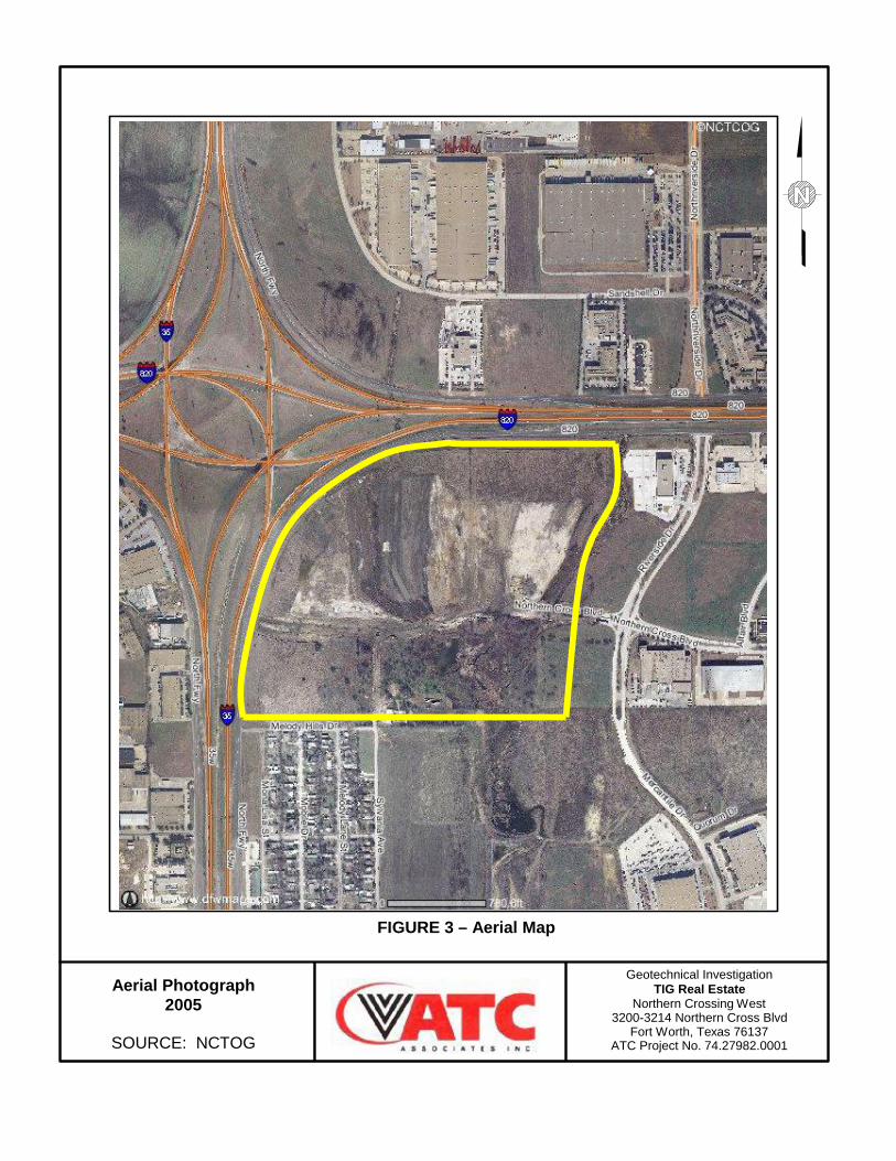
FIGURE 3 – Aerial Map
Aerial Photograph2005
SOURCE: NCTOG
Geotechnical InvestigationTIG Real Estate
Northern Crossing West3200-3214 Northern Cross Blvd
Fort Worth, Texas 76137ATC Project No. 74.27982.0001


APPENDIX A LOGS OF BORINGS

1.5
3.54.5+4.253.02.01.52.02.02.52.0
4.5
14.524.6
28.728.0
17.5
8.5
60 23 PI = 37
DD = 97.3 pcf
50=0.50"50=1.625"
50=1.25"50=1.75"
50=0.25"50=0.50"
1
2
3
4
5
TOPSOIL Clay with Organics and RootsCLAY, Stiff to Hard, Tan to Brown with LimestonePieces, Moist
Red at 9.0 Feet
LIMESTONE, Tan Weathered
LIMESTONE Gray, with Gray Shale Seams
End of Boring at 22 Feet. No groundwater wasencountered.
ST
ST
ST
ST
ST
THD
THD
THD
1.0
13.5
16.5
22.0
ofCave Depth
ft.ft.ft.ft.ft.ft.
SSSTCARCCUCT
- Driven Split Spoon- Pressed Shelby Tube- Continuous Flight Auger- Rock Core- Cuttings- Continuous Tube
HSACFADCMD
- Hollow Stem Augers- Continuous Flight Augers- Driving Casing- Mud Drilling
CLIENT
PROJECT NAME
PROJECT LOCATION
TIG Real EstateNorthern Crossing WestSEC Loop 820 & I-35WFort Worth, TX
Date Started
Date Completed
Drill Foreman
Inspector
Boring Method
Hammer Wt.
Hammer Drop
Spoon Sampler OD
Rock Core Dia.
Shelby Tube OD
140302-3
lbs.
in.
in.
in.
in.
BORING #
JOB #
DRAWN BY
APPROVED BY
B-174.27982.0001JTSMG
5
10
15
20
1 1Page
DRILLING and SAMPLING INFORMATION
Sample Type
11/15/0611/15/06CTKDCFA
Noted on Drilling ToolsAt Completion (in augers)At Completion (open hole)AfterAfter
hourshours
SURFACE ELEVATION 618.5 FT MSL
Depth to Groundwater Boring Method
SOIL CLASSIFICATION
BORING LOG
TEST DATA
1555 Valwood Parkway, Suite 160Carrollton, TX 75006
972-919-3309Fax 972-919-3395

4.5+4.5+4.5+4.5+2.53.0
4.5+3.52.5
4.5+
4.5+
19.4
17.016.8
23.8
8.5
35 16 PI = 19
50=0.50"50=0.25"
50=0.625"50=0.25"
1
2
3
4
5
TOPSOIL Clay with Organics and RootsCLAY, Hard, Brown to Tan with Limestone Pieces,Moist
Red at 4.0 Feet
LIMESTONE, Tan, Weathered with Tan Clay SeamsCLAY, Hard, Tan with Tan Weathered LimestoneLayers, Moist
LIMESTONE Gray with Shale Seams
End of Boring at 22 Feet. No groundwater wasencountered.
ST
ST
ST
ST
ST
THD
THD
1.0
9.010.0
16.0
22.0
ofCave Depth
ft.ft.ft.ft.ft.ft.
Hammer Wt.
Hammer Drop
Spoon Sampler OD
Rock Core Dia.
Shelby Tube OD
140302-3
lbs.
in.
in.
in.
in.
BORING #
JOB #
DRAWN BY
APPROVED BY
B-274.27982.0001JTSMG
5
10
15
20
1 1Page
DRILLING and SAMPLING INFORMATION
Sample Type
11/15/0611/15/06CTKDCFA
Noted on Drilling ToolsAt Completion (in augers)At Completion (open hole)AfterAfter
hourshours
SURFACE ELEVATION 622.8 FT MSL
Depth to Groundwater Boring Method
SOIL CLASSIFICATION
BORING LOG
TEST DATA
1555 Valwood Parkway, Suite 160Carrollton, TX 75006
972-919-3309Fax 972-919-3395
SSSTCARCCUCT
- Driven Split Spoon- Pressed Shelby Tube- Continuous Flight Auger- Rock Core- Cuttings- Continuous Tube
HSACFADCMD
- Hollow Stem Augers- Continuous Flight Augers- Driving Casing- Mud Drilling
CLIENT
PROJECT NAME
PROJECT LOCATION
TIG Real EstateNorthern Crossing WestSEC Loop 820 & I-35WFort Worth, TX
Date Started
Date Completed
Drill Foreman
Inspector
Boring Method

1.7
4.5+3.53.02.01.52.52.251.754.5+4.5+
4.5+
15.9
29.9
18.0
17.6
26.0
15.8
56 23
Swell = 0.67%
DD = 107.5 pcf
PI = 33
50=0.625"50=0.25"
50=1.00"50=0.75"
1
2
3
4
5
TOPSOIL Clay with Organics and RootsCLAY, Hard, Tan to Brown with Limestone Pieces,Moist
CLAY, Hard, Tan to Rust with Weathered LimestonePieces and Seams
LIMESTONE, Tan, Weathered
LIMESTONE Gray with Gray Shale Layers
End of Boring at 23 Feet. No groundwater wasencountered.
ST
ST
ST
ST
ST
THD
THD
1.0
9.0
15.0
16.5
23.0
ofCave Depth
ft.ft.ft.ft.ft.ft.
SSSTCARCCUCT
- Driven Split Spoon- Pressed Shelby Tube- Continuous Flight Auger- Rock Core- Cuttings- Continuous Tube
HSACFADCMD
- Hollow Stem Augers- Continuous Flight Augers- Driving Casing- Mud Drilling
CLIENT
PROJECT NAME
PROJECT LOCATION
TIG Real EstateNorthern Crossing WestSEC Loop 820 & I-35WFort Worth, TX
Date Started
Date Completed
Drill Foreman
Inspector
Boring Method
Hammer Wt.
Hammer Drop
Spoon Sampler OD
Rock Core Dia.
Shelby Tube OD
140302-3
lbs.
in.
in.
in.
in.
BORING #
JOB #
DRAWN BY
APPROVED BY
B-374.27982.0001JTSMG
5
10
15
20
1 1Page
DRILLING and SAMPLING INFORMATION
Sample Type
11/15/0611/15/06CTKDCFA
Noted on Drilling ToolsAt Completion (in augers)At Completion (open hole)AfterAfter
hourshours
SURFACE ELEVATION 616.5 FT MSL
Depth to Groundwater Boring Method
SOIL CLASSIFICATION
BORING LOG
TEST DATA
1555 Valwood Parkway, Suite 160Carrollton, TX 75006
972-919-3309Fax 972-919-3395

SANDY CLAY Gray, FillCLAY, Hard, Dark Brown with Limestone Nodules,Moist
Calcareous at 5.0 Feet
LIMESTONE, Tan, WeatheredLIMESTONE Gray with occasional Shale Seams
Grey Shale Seam at 21-22 Feet
End of Boring at 25 Feet. No groundwater wasencountered.
ST
ST
ST
ST
ST
ST
ST
THD
THD
1.0
18.019.0
25.0
ofCave Depth
ft.ft.ft.ft.ft.ft.
SSSTCARCCUCT
- Driven Split Spoon- Pressed Shelby Tube- Continuous Flight Auger- Rock Core- Cuttings- Continuous Tube
HSACFADCMD
- Hollow Stem Augers- Continuous Flight Augers- Driving Casing- Mud Drilling
CLIENT
PROJECT NAME
PROJECT LOCATION
TIG Real EstateNorthern Crossing WestSEC Loop 820 & I-35WFort Worth, TX
Date Started
Date Completed
Drill Foreman
Inspector
Boring Method
Hammer Wt.
Hammer Drop
Spoon Sampler OD
Rock Core Dia.
Shelby Tube OD
140302-3
lbs.
in.
in.
in.
in.
BORING #
JOB #
DRAWN BY
APPROVED BY
B-474.27982.0001JTSMG
5
10
15
20
25
4.2
4.5+4.5+4.5+4.5+4.5+4.53.5
1.5
2.5
4.5+
18.617.3
17.016.9
20.9
13.0
DD = 116.5 pcf
50=0.75"50=0.50"
50=0.75"50=0.50"
1
2
3
4
5
6
7
1 1Page
DRILLING and SAMPLING INFORMATION
Sample Type
11/18/0611/18/06JCKDCFA
Noted on Drilling ToolsAt Completion (in augers)At Completion (open hole)AfterAfter
hourshours
SURFACE ELEVATION 619.7 FT MSL
Depth to Groundwater Boring Method
SOIL CLASSIFICATION
BORING LOG
TEST DATA
1555 Valwood Parkway, Suite 160Carrollton, TX 75006
972-919-3309Fax 972-919-3395

2.04.5+4.5+4.5+4.5+4.0
4.5+
3.5
2.5
4.5+
22.1
24.2
19.9
24.3
19.0
12.1
50 22 PI = 28
50=2.75"50=1.25"
50=0.50"50=0.00"
1
2
3
4
5
6
7
CLAY Dark Brown, FillCLAY Dark Brown
Tan to Gray with Calcareous Seams at 8.0 Feet
LIMESTONE, Tan, Weathered
LIMESTONE Gray with occasional Shale Seams
End of Boring at 25 Feet. No groundwater wasencountered.
ST
ST
ST
ST
ST
ST
ST
THD
THD
1.0
18.5
20.0
25.0
ofCave Depth
ft.ft.ft.ft.ft.ft.
SSSTCARCCUCT
- Driven Split Spoon- Pressed Shelby Tube- Continuous Flight Auger- Rock Core- Cuttings- Continuous Tube
HSACFADCMD
- Hollow Stem Augers- Continuous Flight Augers- Driving Casing- Mud Drilling
CLIENT
PROJECT NAME
PROJECT LOCATION
TIG Real EstateNorthern Crossing WestSEC Loop 820 & I-35WFort Worth, TX
Date Started
Date Completed
Drill Foreman
Inspector
Boring Method
Hammer Wt.
Hammer Drop
Spoon Sampler OD
Rock Core Dia.
Shelby Tube OD
140302-3
lbs.
in.
in.
in.
in.
BORING #
JOB #
DRAWN BY
APPROVED BY
B-574.27982.0001JTSMG
5
10
15
20
25
1 1Page
DRILLING and SAMPLING INFORMATION
Sample Type
11/18/0611/18/06JCKDCFA
Noted on Drilling ToolsAt Completion (in augers)At Completion (open hole)AfterAfter
hourshours
SURFACE ELEVATION 620.5 FT MSL
Depth to Groundwater Boring Method
SOIL CLASSIFICATION
BORING LOG
TEST DATA
1555 Valwood Parkway, Suite 160Carrollton, TX 75006
972-919-3309Fax 972-919-3395

4.5+1.50.50.51.50.51.5
1.0
2.5
4.5+
12.6
30.0
28.2
23.9
9.0
59 23 PI = 36
50=0.50"50=0.50"
50=0.75"50=0.00"
50=0.50"50=0.25"
1
2
3
4
5
6
7
SANDY CLAY Light Gray, Fill
CLAY, Medium Stiff to Stiff, Dark Brown withLimestone Fragments, Moist
Light Brown at 8.0 Feet
Occasional Limestone Seams 14.5 Feet
LIMESTONE, Tan, Weathered
LIMESTONE, Gray
End of Boring at 25 Feet. No groundwater wasencountered.
ST
ST
ST
ST
ST
ST
THDST
THD
THD
2.5
18.0
20.0
25.0
ofCave Depth
ft.ft.ft.ft.ft.ft.
SSSTCARCCUCT
- Driven Split Spoon- Pressed Shelby Tube- Continuous Flight Auger- Rock Core- Cuttings- Continuous Tube
HSACFADCMD
- Hollow Stem Augers- Continuous Flight Augers- Driving Casing- Mud Drilling
CLIENT
PROJECT NAME
PROJECT LOCATION
TIG Real EstateNorthern Crossing WestSEC Loop 820 & I-35WFort Worth, TX
Date Started
Date Completed
Drill Foreman
Inspector
Boring Method
Hammer Wt.
Hammer Drop
Spoon Sampler OD
Rock Core Dia.
Shelby Tube OD
140302-3
lbs.
in.
in.
in.
in.
BORING #
JOB #
DRAWN BY
APPROVED BY
B-674.27982.0001JTSMG
5
10
15
20
25
1 1Page
DRILLING and SAMPLING INFORMATION
Sample Type
11/17/0611/17/06JCKDCFA
Noted on Drilling ToolsAt Completion (in augers)At Completion (open hole)AfterAfter
hourshours
SURFACE ELEVATION 617.3 FT MSL
Depth to Groundwater Boring Method
SOIL CLASSIFICATION
BORING LOG
TEST DATA
1555 Valwood Parkway, Suite 160Carrollton, TX 75006
972-919-3309Fax 972-919-3395

Depth to Groundwater Boring Method
SOIL CLASSIFICATION
BORING LOG
TEST DATA
1555 Valwood Parkway, Suite 160Carrollton, TX 75006
972-919-3309Fax 972-919-3395
1.6
1.54.5+2.51.00.50.50.5
1.0
2.5
4.5+
20.4
26.727.8
27.0
26.5
10.7
7.5
63 24 PI = 39
DD = 97.9 pcf
50=0.50"50=0.25"
50=1.00"50=0.00"
1
2
3
4
5
6
7
FILL, Clay, Dark Brown
CLAY, Medium Stiff, Dark Brown with LimestoneNodules
Occasional Small Limestone Seams 14.5 Feet
LIMESTONE, Tan, Weathered
LIMESTONE Gray
End of Boring at 25 Feet. No groundwater wasencountered.
ST
ST
ST
ST
ST
ST
ST
THD
THD
4.0
16.5
20.0
25.0
ofCave Depth
ft.ft.ft.ft.ft.ft.
SSSTCARCCUCT
- Driven Split Spoon- Pressed Shelby Tube- Continuous Flight Auger- Rock Core- Cuttings- Continuous Tube
HSACFADCMD
- Hollow Stem Augers- Continuous Flight Augers- Driving Casing- Mud Drilling
CLIENT
PROJECT NAME
PROJECT LOCATION
TIG Real EstateNorthern Crossing WestSEC Loop 820 & I-35WFort Worth, TX
Date Started
Date Completed
Drill Foreman
Inspector
Boring Method
Hammer Wt.
Hammer Drop
Spoon Sampler OD
Rock Core Dia.
Shelby Tube OD
140302-3
lbs.
in.
in.
in.
in.
BORING #
JOB #
DRAWN BY
APPROVED BY
B-774.27982.0001JTSMG
5
10
15
20
25
1 1Page
DRILLING and SAMPLING INFORMATION
Sample Type
11/17/0611/17/06JCKDCFA
Noted on Drilling ToolsAt Completion (in augers)At Completion (open hole)AfterAfter
hourshours
SURFACE ELEVATION 616.1 FT MSL

1.7
4.5+4.5+4.02.00.50.50.5
1.5
4.5
4.5+
19.2
29.3
22.0
20.5
20.1
18.6
54 23 PI = 31
DD = 101.1 pcf
Swell = 1.08%
50=0.50"50=0.50"
50=0.00"50=0.00"
1
2
3
4
5
6
7
FILL, Clay, Dark Brown and Light Brown
CLAY, Medium Stiff, Dark Brown
Light Brown with Light Gray Limestone Pieces
Tan, Calcareous with Limestone Seams and ThinLayers
Limestone Layer 14 - 15 Feet
Gray Shale Seam 18 - 19 Feet
LIMESTONE Gray
End of Boring at 25 Feet. Groundwater wasencountered at 23.0 Feet. Caved at 25.
ST
ST
ST
ST
ST
ST
ST
THD
THD
4.0
20.0
25.0
ofCave Depth
ft.ft.ft.ft.ft.ft.
SSSTCARCCUCT
- Driven Split Spoon- Pressed Shelby Tube- Continuous Flight Auger- Rock Core- Cuttings- Continuous Tube
20.0
25.0
HSACFADCMD
- Hollow Stem Augers- Continuous Flight Augers- Driving Casing- Mud Drilling
CLIENT
PROJECT NAME
PROJECT LOCATION
TIG Real EstateNorthern Crossing WestSEC Loop 820 & I-35WFort Worth, TX
Date Started
Date Completed
Drill Foreman
Inspector
Boring Method
Hammer Wt.
Hammer Drop
Spoon Sampler OD
Rock Core Dia.
Shelby Tube OD
140302-3
lbs.
in.
in.
in.
in.
BORING #
JOB #
DRAWN BY
APPROVED BY
B-874.27982.0001JTSMG
5
10
15
20
25
1 1Page
DRILLING and SAMPLING INFORMATION
Sample Type
11/17/0611/17/06JCKDCFA
Noted on Drilling ToolsAt Completion (in augers)At Completion (open hole)AfterAfter
hourshours
SURFACE ELEVATION 616.8 FT MSL
Depth to Groundwater Boring Method
SOIL CLASSIFICATION
BORING LOG
TEST DATA
1555 Valwood Parkway, Suite 160Carrollton, TX 75006
972-919-3309Fax 972-919-3395

THD
3.0
22.0
25.0
3.7
1.53.52.51.50.50.50.5
1.5
2.5
4.5+
4.5+
29.2
32.3
24.3
22.4
15.0
13.6
53 22
Swell = 1.197%
PI = 31
DD = 111.5 pcf
50=0.75"50=0.125"
1
2
3
4
5
6
7
8
FILL, Sandy Clay, Light Gray
CLAY, Medium Stiff, Dark Brown
Light Brown with Light Gray Limestone Nodules
Tan and Gray, Calcareous with Limestone Seam
Limestone Seam 20-20.5 Feet
LIMESTONE Gray with occasional Shale Seams
End of Boring at 25 Feet. No groundwater wasencountered.
ST
ST
ST
ST
ST
ST
ST
ST
ofCave Depth
ft.ft.ft.ft.ft.ft.
SSSTCARCCUCT
- Driven Split Spoon- Pressed Shelby Tube- Continuous Flight Auger- Rock Core- Cuttings- Continuous Tube
HSACFADCMD
- Hollow Stem Augers- Continuous Flight Augers- Driving Casing- Mud Drilling
CLIENT
PROJECT NAME
PROJECT LOCATION
TIG Real EstateNorthern Crossing WestSEC Loop 820 & I-35WFort Worth, TX
Date Started
Date Completed
Drill Foreman
Inspector
Boring Method
Hammer Wt.
Hammer Drop
Spoon Sampler OD
Rock Core Dia.
Shelby Tube OD
140302-3
lbs.
in.
in.
in.
in.
BORING #
JOB #
DRAWN BY
APPROVED BY
B-974.27982.0001JTSMG
5
10
15
20
25
1 1Page
DRILLING and SAMPLING INFORMATION
Sample Type
11/18/0611/18/06JCKDCFA
Noted on Drilling ToolsAt Completion (in augers)At Completion (open hole)AfterAfter
hourshours
SURFACE ELEVATION 618.0 FT MSL
Depth to Groundwater Boring Method
SOIL CLASSIFICATION
BORING LOG
TEST DATA
1555 Valwood Parkway, Suite 160Carrollton, TX 75006
972-919-3309Fax 972-919-3395

1.9
1.01.52.01.01.50.51.5
1.5
3.5
31.1
23.9
26.6
22.0
18.9
12.7
57 23 PI = 34
DD = 106.1 pcf
50=1.625"50=2.25"
50=0.75"50=0.50"
1
2
3
4
5
6
7
FILL, Clay, Dark Brown
CLAY Dark Brown
Light Brown to Light Gray with Limestone Nodules
Light Brown to Light Gray Calcereous
Limestone Seam 16.5-17.0 Feet
LIMESTONE Gray with Occasional Shale Seams
End of Boring at 25 Feet. No groundwater wasencountered.
ST
ST
ST
ST
ST
ST
ST
THD
THD
3.0
19.5
25.0
ofCave Depth
ft.ft.ft.ft.ft.ft.
SSSTCARCCUCT
- Driven Split Spoon- Pressed Shelby Tube- Continuous Flight Auger- Rock Core- Cuttings- Continuous Tube
HSACFADCMD
- Hollow Stem Augers- Continuous Flight Augers- Driving Casing- Mud Drilling
CLIENT
PROJECT NAME
PROJECT LOCATION
TIG Real EstateNorthern Crossing WestSEC Loop 820 & I-35WFort Worth, TX
Date Started
Date Completed
Drill Foreman
Inspector
Boring Method
Hammer Wt.
Hammer Drop
Spoon Sampler OD
Rock Core Dia.
Shelby Tube OD
140302-3
lbs.
in.
in.
in.
in.
BORING #
JOB #
DRAWN BY
APPROVED BY
B-1074.27982.0001JTSMG
5
10
15
20
25
1 1Page
DRILLING and SAMPLING INFORMATION
Sample Type
11/18/0611/18/06JCKDCFA
Noted on Drilling ToolsAt Completion (in augers)At Completion (open hole)AfterAfter
hourshours
SURFACE ELEVATION 614.5 FT MSL
Depth to Groundwater Boring Method
SOIL CLASSIFICATION
BORING LOG
TEST DATA
1555 Valwood Parkway, Suite 160Carrollton, TX 75006
972-919-3309Fax 972-919-3395

4.5+4.5+4.5+4.5+4.5+4.5+4.5
4.5+
2.5
4.5+
5.8
13.021.421.7
20.0
8.1
34 15 PI = 19
50=0.50"50=0.125"
50=0.75"50=0.375"
1
2
3
4
5
6
TOPSOIL Clay with Organics and Roots CLAY, Hard, Brown to Tan with Limestone Pieces
Rust at 3.0 Feet
Tan to Rust with Tan Weathered LimestoneLayers Hard Limestone Layer 11.0 to 11.5 Feet
LIMESTONE Gray, with occasional Gray ShaleSeams
End of Boring at 22 Feet. No groundwater wasencountered.
ST
ST
ST
ST
ST
ST
THD
THD
1.0
16.0
22.0
ofCave Depth
ft.ft.ft.ft.ft.ft.
SSSTCARCCUCT
- Driven Split Spoon- Pressed Shelby Tube- Continuous Flight Auger- Rock Core- Cuttings- Continuous Tube
HSACFADCMD
- Hollow Stem Augers- Continuous Flight Augers- Driving Casing- Mud Drilling
CLIENT
PROJECT NAME
PROJECT LOCATION
TIG Real EstateNorthern Crossing WestSEC Loop 820 & I-35WFort Worth, TX
Date Started
Date Completed
Drill Foreman
Inspector
Boring Method
Hammer Wt.
Hammer Drop
Spoon Sampler OD
Rock Core Dia.
Shelby Tube OD
140302-3
lbs.
in.
in.
in.
in.
BORING #
JOB #
DRAWN BY
APPROVED BY
B-1174.27982.0001JTSMG
5
10
15
20
1 1Page
DRILLING and SAMPLING INFORMATION
Sample Type
11/16/0611/16/06CTKDCFA
Noted on Drilling ToolsAt Completion (in augers)At Completion (open hole)AfterAfter
hourshours
SURFACE ELEVATION 622.5 FT MSL
Depth to Groundwater Boring Method
SOIL CLASSIFICATION
BORING LOG
TEST DATA
1555 Valwood Parkway, Suite 160Carrollton, TX 75006
972-919-3309Fax 972-919-3395

1.251.54.04.0
4.5+
15.6
16.8
22.0
24.8
14.5
7.9
58 23
DD =106.0 pcf
PI = 35
50=1.00"50=0.75"
50=0.50"50=0.00"
1
2
3
4.0
3.54.5+4.5+
4
5
TOPSOIL Clay with Organics and RootsCLAY, Hard to Stiff, Light Brown with LimestoneNodules
Slightly Shaley at 7.5 Feet
SHALE, Gray
LIMESTONE Gray with Small Shale Seams
End of Boring at 19 Feet. No groundwater wasencountered.
ST
ST
ST
ST
ST
THD
THD
1.0
13.5
16.0
19.0
ofCave Depth
ft.ft.ft.ft.ft.ft.
SSSTCARCCUCT
- Driven Split Spoon- Pressed Shelby Tube- Continuous Flight Auger- Rock Core- Cuttings- Continuous Tube
HSACFADCMD
- Hollow Stem Augers- Continuous Flight Augers- Driving Casing- Mud Drilling
CLIENT
PROJECT NAME
PROJECT LOCATION
TIG Real EstateNorthern Crossing WestSEC Loop 820 & I-35WFort Worth, TX
Date Started
Date Completed
Drill Foreman
Inspector
Boring Method
Hammer Wt.
Hammer Drop
Spoon Sampler OD
Rock Core Dia.
Shelby Tube OD
140302-3
lbs.
in.
in.
in.
in.
BORING #
JOB #
DRAWN BY
APPROVED BY
B-1274.27982.0001JTSMG
5
10
15
1 1Page
DRILLING and SAMPLING INFORMATION
Sample Type
11/16/0611/16/06JCKDCFA
Noted on Drilling ToolsAt Completion (in augers)At Completion (open hole)AfterAfter
hourshours
SURFACE ELEVATION 620.0 FT MSL
Depth to Groundwater Boring Method
SOIL CLASSIFICATION
BORING LOG
TEST DATA
1555 Valwood Parkway, Suite 160Carrollton, TX 75006
972-919-3309Fax 972-919-3395

SSSTCARCCUCT
- Driven Split Spoon- Pressed Shelby Tube- Continuous Flight Auger- Rock Core- Cuttings- Continuous Tube
HSACFADCMD
- Hollow Stem Augers- Continuous Flight Augers- Driving Casing- Mud Drilling
CLIENT
PROJECT NAME
PROJECT LOCATION
TIG Real EstateNorthern Crossing WestSEC Loop 820 & I-35WFort Worth, TX
Date Started
Date Completed
Drill Foreman
Inspector
Boring Method
Hammer Wt.
Hammer Drop
Spoon Sampler OD
Rock Core Dia.
Shelby Tube OD
140302-3
lbs.
in.
in.
in.
in.
BORING #
JOB #
DRAWN BY
APPROVED BY
B-1374.27982.0001JTSMG
4.3
1.02.0
4.5+4.5+4.5+4.5+
2.0
4.5+
18.4
18.9
18.318.1
11.9
26.4
56 23 PI = 33
DD = 113.7 pcf
50=0.125"50=0.00"
50=0.75"50=0.75"
50=0.00"50=0.00"
1
2
3
4
5
6
TOPSOIL Clay with Organics and RootsCLAY, Hard, Dark Brown
Reddish brown with Limestone Nodules, Moist
Large Limestone Pieces at 7.0 Feet
LIMESTONE Tan, Weathered
LIMESTONE Gray, Occasional Shale Seams
End of Boring at 24 Feet. No groundwater wasencountered.
ST
ST
ST
ST
ST
ST
THD
THD
THD
1.0
14.5
18.5
24.0
ofCave Depth
ft.ft.ft.ft.ft.ft.
5
10
15
20
1 1Page
DRILLING and SAMPLING INFORMATION
Sample Type
11/16/0611/16/06JCKDCFA
Noted on Drilling ToolsAt Completion (in augers)At Completion (open hole)AfterAfter
hourshours
SURFACE ELEVATION 622.0 FT MSL
Depth to Groundwater Boring Method
SOIL CLASSIFICATION
BORING LOG
TEST DATA
1555 Valwood Parkway, Suite 160Carrollton, TX 75006
972-919-3309Fax 972-919-3395

3.54.5+4.5+4.5+4.5+4.5+4.5+4.5+4.5+4.5+
4.5+
4.5+
17.1
7.99.4
12.4
8.8
47 21 PI = 19Swell = 0.673%
50=0.625"50=0.25"
50=0.75"50=0.375"
1
2
3
4
5
6
7
8
TOPSOIL Clay with Organics and RootsCLAY, Hard, Dark Brown to Tan with LimestonePieces, Moist
Tan to Rust with Limestone Pieces
LIMESTONE Tan Weathered with Tan to Rust ClaySeams
LIMESTONE Tan, to Gray with Gray Shale Seams
End of Boring at 25 Feet. No groundwater wasencountered.
ST
ST
ST
ST
ST
ST
ST
ST
THD
THD
1.0
13.0
19.5
25.0
ofCave Depth
ft.ft.ft.ft.ft.ft.
SSSTCARCCUCT
- Driven Split Spoon- Pressed Shelby Tube- Continuous Flight Auger- Rock Core- Cuttings- Continuous Tube
HSACFADCMD
- Hollow Stem Augers- Continuous Flight Augers- Driving Casing- Mud Drilling
CLIENT
PROJECT NAME
PROJECT LOCATION
TIG Real EstateNorthern Crossing WestSEC Loop 820 & I-35WFort Worth, TX
Date Started
Date Completed
Drill Foreman
Inspector
Boring Method
Hammer Wt.
Hammer Drop
Spoon Sampler OD
Rock Core Dia.
Shelby Tube OD
140302-3
lbs.
in.
in.
in.
in.
BORING #
JOB #
DRAWN BY
APPROVED BY
B-1474.27982.0001JTSMG
5
10
15
20
25
1 1Page
DRILLING and SAMPLING INFORMATION
Sample Type
11/16/0611/16/06CTKDCFA
Noted on Drilling ToolsAt Completion (in augers)At Completion (open hole)AfterAfter
hourshours
SURFACE ELEVATION 622.2 FT MSL
Depth to Groundwater Boring Method
SOIL CLASSIFICATION
BORING LOG
TEST DATA
1555 Valwood Parkway, Suite 160Carrollton, TX 75006
972-919-3309Fax 972-919-3395

TOPSOIL Clay with Organics and Roots CLAY Dark Brown with Limestone Nodules Limestone Seam 1.5-2.0 Feet
Brown to Light Gray with Limestone Nodules at8.0 Feet
LIMESTONE, Tan, Weathered
SHALE Gray with Gray Limestone Seams Limestone Seam 17-17.5 Feet
LIMESTONE Gray with Occasional Shale Seams
End of Boring at 21 Feet. No groundwater wasencountered.
35
1.3
16.7
18.2
14.8
12.5
58 23 DD = 104.0 pcfPI = 35
50=1.50"50=2.00"
50=0.50"50=0.00"
1
2
3
45
ST
SPT
ST
STST
THD
THD
1.0
14.5
16.0
19.5
21.0
ofCave Depth
ft.ft.ft.ft.ft.ft.
SSSTCARCCUCT
- Driven Split Spoon- Pressed Shelby Tube- Continuous Flight Auger- Rock Core- Cuttings- Continuous Tube
HSACFADCMD
- Hollow Stem Augers- Continuous Flight Augers- Driving Casing- Mud Drilling
CLIENT
PROJECT NAME
PROJECT LOCATION
TIG Real EstateNorthern Crossing WestSEC Loop 820 & I-35WFort Worth, TX
Date Started
Date Completed
Drill Foreman
Inspector
Boring Method
Hammer Wt.
Hammer Drop
Spoon Sampler OD
Rock Core Dia.
Shelby Tube OD
140302-3
lbs.
in.
in.
in.
in.
BORING #
JOB #
DRAWN BY
APPROVED BY
B-1574.27982.0001JTSMG
5
10
15
20
1 1Page
DRILLING and SAMPLING INFORMATION
Sample Type
11/16/0611/16/06JCKDCFA
Noted on Drilling ToolsAt Completion (in augers)At Completion (open hole)AfterAfter
hourshours
SURFACE ELEVATION 617.2 FT MSL
Depth to Groundwater Boring Method
SOIL CLASSIFICATION
BORING LOG
TEST DATA
1555 Valwood Parkway, Suite 160Carrollton, TX 75006
972-919-3309Fax 972-919-3395

4.5+4.5+4.5+4.5+4.5+4.5+
4.5+
4.5+
4.5+
4.5+
19.3
14.0
21.7
18.4
20.1
55 23 PI = 32
50=1.00"50=0.50"
1
2
3
4
5
6
7
8
TOPSOIL Clay with Organics and RootsCLAY Dark Brown
Light Brown with Limestone Fragments
LIMESTONE Gray with occasional Shale Seams
End of Boring at 25 Feet. No groundwater wasencountered.
ST
ST
ST
ST
ST
ST
ST
ST
THD
1.0
22.0
25.0
ofCave Depth
ft.ft.ft.ft.ft.ft.
SSSTCARCCUCT
- Driven Split Spoon- Pressed Shelby Tube- Continuous Flight Auger- Rock Core- Cuttings- Continuous Tube
HSACFADCMD
- Hollow Stem Augers- Continuous Flight Augers- Driving Casing- Mud Drilling
CLIENT
PROJECT NAME
PROJECT LOCATION
TIG Real EstateNorthern Crossing WestSEC Loop 820 & I-35WFort Worth, TX
Date Started
Date Completed
Drill Foreman
Inspector
Boring Method
Hammer Wt.
Hammer Drop
Spoon Sampler OD
Rock Core Dia.
Shelby Tube OD
140302-3
lbs.
in.
in.
in.
in.
BORING #
JOB #
DRAWN BY
APPROVED BY
B-1674.27982.0001JTSMG
5
10
15
20
25
1 1Page
DRILLING and SAMPLING INFORMATION
Sample Type
11/18/0611/18/06JCKDCFA
Noted on Drilling ToolsAt Completion (in augers)At Completion (open hole)AfterAfter
hourshours
SURFACE ELEVATION 627.1 FT MSL
Depth to Groundwater Boring Method
SOIL CLASSIFICATION
BORING LOG
TEST DATA
1555 Valwood Parkway, Suite 160Carrollton, TX 75006
972-919-3309Fax 972-919-3395

4.5+4.5+2.52.52.04.0
4.5+
4.5+
4.5+
10.0
19.223.0
17.7
19.1
62 24Swell = 0.668%PI = 38
50=1.75"50=1.50"
50=0.00"50=0.00"
1
2
3
4
5
6
FILL, Sandy Clay, Light Gray
<<U>CLAY, Dark Brown with Limestone Pieces,Moist
Light Brown at 6.0 Feet
Calcareous with bentonine seams at 10.0 Feet
Tan Limestone Seam 13.5-14 Feet
Limestone Seam 15-15.5 Feet
Gray Shale Seams 18-19.5 Feet
LIMESTONE Gray
Extremely Hard 21-22 FeetEnd of Boring, Refusal at 22 Feet. No groundwaterwas encountered.
ST
ST
ST
ST
ST
ST
THD
THD
2.0
19.5
22.0
ofCave Depth
ft.ft.ft.ft.ft.ft.
SSSTCARCCUCT
- Driven Split Spoon- Pressed Shelby Tube- Continuous Flight Auger- Rock Core- Cuttings- Continuous Tube
HSACFADCMD
- Hollow Stem Augers- Continuous Flight Augers- Driving Casing- Mud Drilling
CLIENT
PROJECT NAME
PROJECT LOCATION
TIG Real EstateNorthern Crossing WestSEC Loop 820 & I-35WFort Worth, TX
Date Started
Date Completed
Drill Foreman
Inspector
Boring Method
Hammer Wt.
Hammer Drop
Spoon Sampler OD
Rock Core Dia.
Shelby Tube OD
140302-3
lbs.
in.
in.
in.
in.
BORING #
JOB #
DRAWN BY
APPROVED BY
B-1774.27982.0001JTSMG
5
10
15
20
1 1Page
DRILLING and SAMPLING INFORMATION
Sample Type
11/18/0611/18/06JCKDCFA
Noted on Drilling ToolsAt Completion (in augers)At Completion (open hole)AfterAfter
hourshours
SURFACE ELEVATION 619.4 FT MSL
Depth to Groundwater Boring Method
SOIL CLASSIFICATION
BORING LOG
TEST DATA
1555 Valwood Parkway, Suite 160Carrollton, TX 75006
972-919-3309Fax 972-919-3395

BORING LOG
TEST DATA
1555 Valwood Parkway, Suite 160Carrollton, TX 75006
972-919-3309Fax 972-919-3395
ofCave Depth
ft.ft.ft.ft.ft.ft.
SSSTCARCCUCT
- Driven Split Spoon- Pressed Shelby Tube- Continuous Flight Auger- Rock Core- Cuttings- Continuous Tube
HSACFADCMD
- Hollow Stem Augers- Continuous Flight Augers- Driving Casing- Mud Drilling
CLIENT
PROJECT NAME
PROJECT LOCATION
TIG Real EstateNorthern Crossing WestSEC Loop 820 & I-35WFort Worth, TX
Date Started
Date Completed
Drill Foreman
Inspector
Boring Method
Hammer Wt.
Hammer Drop
Spoon Sampler OD
Rock Core Dia.
Shelby Tube OD
140302-3
lbs.
in.
in.
in.
in.
BORING #
JOB #
DRAWN BY
APPROVED BY
B-1874.27982.0001JTSMG
5
10
15
20
1 1Page
DRILLING and SAMPLING INFORMATION
Sample Type
11/18/0611/18/06JCKDCFA
Noted on Drilling ToolsAt Completion (in augers)At Completion (open hole)AfterAfter
hourshours
SURFACE ELEVATION 622.5 FT MSL
Depth to Groundwater Boring Method
SOIL CLASSIFICATION
1.52.54.04.0
4.5+1.5
2.0
3.0
4.5+
21.5
21.3
26.2
17.5
10.4
58 23 PI = 35
50=1.00"50=0.75"
50=0.75"50=0.50"
1
2
3
4
5
6
7
TOPSOIL Clay with Organics and RootsCLAY, Stiff to Hard, Dark Brown with LimestoneNodules
Brown at 5.0 Feet
Calcareous with Bentonite Seams at 11.0 Feet
Tan Limestone Seam 12.5-13 Feet
Tan Limestone Seam 15-16 Feet
LIMESTONE Gray with occasional Gray ShaleSeams
End of Boring at 22 Feet. No groundwater wasencountered.
ST
ST
ST
ST
ST
ST
ST
THD
THD
1.0
17.0
22.0

4.5+
4.0
14.4
17.9
17.0
14.3
9.5
50 22
50=2.00"50=1.25"PI = 28
50=0.125"50=0.00"
50=0.75"50=0.00"
50=0.50"50=0.00"
1
2
3
4
5
TOPSOIL Clay with Organics and RootsCLAY, Hard, Brown with Calcareous Nodules, Moist
Light Brown at 6.0 Feet
LIMESTONE Tan, WeatheredCLAY, Tan and Gray, Calcareous with BentoniteSeams and Limestone Nodules
LIMESTONE, Tan Weathered with Clay Seams andLayers
LIMESTONE Gray
End of Boring at 23 Feet. No groundwater wasencountered.
ST
ST
ST
ST
THD
ST
THD
THD
THD
1.0
8.59.5
14.5
18.0
23.0
ofCave Depth
ft.ft.ft.ft.ft.ft.
SSSTCARCCUCT
- Driven Split Spoon- Pressed Shelby Tube- Continuous Flight Auger- Rock Core- Cuttings- Continuous Tube
HSACFADCMD
- Hollow Stem Augers- Continuous Flight Augers- Driving Casing- Mud Drilling
CLIENT
PROJECT NAME
PROJECT LOCATION
TIG Real EstateNorthern Crossing WestSEC Loop 820 & I-35WFort Worth, TX
Date Started
Date Completed
Drill Foreman
Inspector
Boring Method
Hammer Wt.
Hammer Drop
Spoon Sampler OD
Rock Core Dia.
Shelby Tube OD
140302-3
lbs.
in.
in.
in.
in.
BORING #
JOB #
DRAWN BY
APPROVED BY
B-1974.27982.0001JTSMG
5
10
15
20
1 1Page
DRILLING and SAMPLING INFORMATION
Sample Type
11/16/0611/16/06JCKDCFA
Noted on Drilling ToolsAt Completion (in augers)At Completion (open hole)AfterAfter
hourshours
SURFACE ELEVATION 621.7 FT MSL
Depth to Groundwater Boring Method
SOIL CLASSIFICATION
BORING LOG
TEST DATA
1555 Valwood Parkway, Suite 160Carrollton, TX 75006
972-919-3309Fax 972-919-3395

4.5+2.0
4.5+4.5+4.5+4.5+
2.0
3.0
4.5
23.6
15.2
16.3
18.1
Noted on Drilling ToolsAt Completion (in augers)At Completion (open hole)AfterAfter
hourshours
SURFACE ELEVATION 615.0 FT MSL
Depth to Groundwater Boring Method
SOIL CLASSIFICATION
BORING LOG
TEST DATA
1555 Valwood Parkway, Suite 160Carrollton, TX 75006
972-919-3309Fax 972-919-3395
13.0
58 23 PI = 35
50=0.50"50=0.00"
50=0.75"50=0.50"
1
2
3
4
5
6
FILL, Clay Dark Brown
CLAY, Hard, Dark Brown, Moist
Light Brown with Limestone Pieces at 10.0 Feet
LIMESTONE, Tan, Weathered
LIMESTONE, Gray with occasional Shale Seams
Seepage at 24.8End of Boring at 25 Feet. Seepage at 24.8 Feet,Caved at 25
ST
ST
ST
ST
ST
ST
THD
THD
3.5
20.0
22.5
25.0
ofCave Depth
ft.ft.ft.ft.ft.ft.
SSSTCARCCUCT
- Driven Split Spoon- Pressed Shelby Tube- Continuous Flight Auger- Rock Core- Cuttings- Continuous Tube
24.8
25.0
HSACFADCMD
- Hollow Stem Augers- Continuous Flight Augers- Driving Casing- Mud Drilling
CLIENT
PROJECT NAME
PROJECT LOCATION
TIG Real EstateNorthern Crossing WestSEC Loop 820 & I-35WFort Worth, TX
Date Started
Date Completed
Drill Foreman
Inspector
Boring Method
Hammer Wt.
Hammer Drop
Spoon Sampler OD
Rock Core Dia.
Shelby Tube OD
140302-3
lbs.
in.
in.
in.
in.
BORING #
JOB #
DRAWN BY
APPROVED BY
B-2074.27982.0001JTSMG
5
10
15
20
25
1 1Page
DRILLING and SAMPLING INFORMATION
Sample Type
11/16/0611/16/06JCKDCFA