REPORT OF SUBSURFACE EXPLORATION AND … EXPLORATION AND GEOTECHNICAL ANALYSIS ... Report of...
23
REPORT OF SUBSURFACE EXPLORATION AND GEOTECHNICAL ANALYSIS DMA TAMPA RED BRICK BUILDING TAMPA, FLORIDA FOR MRI ARCHITECTURAL GROUP, INC. JANUARY 7, 2015
Transcript of REPORT OF SUBSURFACE EXPLORATION AND … EXPLORATION AND GEOTECHNICAL ANALYSIS ... Report of...
REPORT OF
SUBSURFACE EXPLORATION AND GEOTECHNICAL ANALYSIS
DMA TAMPA RED BRICK BUILDING TAMPA, FLORIDA
FOR
MRI ARCHITECTURAL GROUP, INC.
JANUARY 7, 2015

2815 Directors Row, Suite 500, Orlando, FL 32809 • T: 407-859-8378 • F: 407-859-9599 • www.ecslimited.com
ECS Carolinas, LLP • ECS Florida, LLC • ECS Midwest, LLC • ECS Mid-Atlantic, LLC • ECS Southeast, LLC • ECS Texas, LLP
January 7, 2015
Mr. Pete Ikegami MRI Architectural Group 5032 Goddard Avenue Orlando, Florida 32804
ECS Project No.: 41-1329
Reference: Report of Subsurface Exploration and Geotechnical Engineering Services, DMA Tampa Red Brick Building, 2313 West Lemon Street, Tampa, Florida 33609
Dear Mr. Ikegami: As authorized by acceptance of proposal no. 41-545 Revision 1, dated September 15, 2014, ECS-Florida, LLC (ECS) has completed the subsurface exploration and conducted geotechnical engineering analyses for the proposed building addition located at 2313 West Lemon Street in Tampa, Hillsborough County, Florida. Our report includes the results of our subsurface exploration program, laboratory testing program, and geotechnical engineering analyses is attached. Based on aerial photographs, we understand the subject property is currently developed as the National Guard Armory Facility. It is our understanding the proposed construction will consist of the renovation of the existing brick building as well as adding structural components to the building located near the southeastern portion of the parcel. Structural information was not available at the time of the report preparation; however, we have assumed that the new structural components will be relatively lightly loaded with maximum column loads on the order of 30 kips or less and wall loads of 3 kips per lineal foot. We have also assumed that cuts and/or fills will be on the order of two feet or less to reach proposed finished floor elevation. This geotechnical evaluation includes an evaluation of the subsurface soil and groundwater conditions of the site and general area as described in scope of services identified in our proposal. No other additional issues were explored, requested or proposed during this evaluation. The conclusions and recommendations presented within this report are based upon a reasonable level of exploration within normal bounds and standards of professional practice for a site in this particular geographic and geologic setting. This report has been prepared to aid in the evaluation of this site and to assist the Owner and Engineer in the feasibility study of the project. The report scope is limited to the specific project and location described, and the project description represents our understanding of the significant aspects relevant to soil and foundation characteristics, based on two soil test borings and geotechnical analysis.


TABLE OF CONTENTS PAGE
PROJECT OVERVIEW
Introduction 1
Scope of Service 1
Purposes of Exploration 2
EXPLORATION PROCEDURES
Subsurface Exploration Procedures 3
Laboratory Testing Program 3
EXPLORATION RESULTS
Soil Conditions 4
Groundwater Observations 4
Existing Foundation 4
ANALYSES AND RECOMMENDATIONS
Foundation 5
Floor Slab Design 6
Earthwork Operations 6
Subgrade Preparation 6
Fill Placement 6
Borrow Suitability 7
Pavement Considerations 7
Subgrade 8
Base Course 8
Effects of Groundwater 8
Landscape Drains and Curbing 9
Construction Considerations 9
Report Limitations 10
APPENDIX

DMA – Tampa Red Brick Building ECS Job No.: 41-1329 January 7, 2015 Page 1 of 11
PROJECT OVERVIEW Introduction This report presents the results of our subsurface exploration and geotechnical engineering analysis for the proposed building addition to the National Guard Armory Facility located at 2313 West Lemon Street in Tampa, Florida, as authorized by your office. In preparing this report, we have utilized information from our current subsurface exploration. The site and boring locations are shown on the Boring Location Plan included in the Appendix. It is our understanding the proposed construction will consist of the renovation of the existing brick building as well as adding structural components to the building located near the southeastern portion of the parcel. Structural information was not available at the time of the report preparation; however, we have assumed that the new structural components will be relatively lightly loaded with maximum column loads on the order of 30 kips or less and wall loads of 3 kips per lineal foot. We have also assumed that cuts and/or fills will be on the order of two feet or less to reach proposed finished floor elevation. The description of the proposed project as given above is based on information provided to us by your office. If any of this information is in error, either due to our misunderstanding or due to any design changes which may occur later, we recommend that ECS be contacted so that we may review our recommendations and provide any alternate or additional recommendations considered warranted at that time. Scope of Service The conclusions and recommendations contained in this report are based on our field subsurface explorations and review of available geologic and/or geotechnical data. The recent subsurface exploration program included two soil borings, extended to depths of approximately 10 feet and 30 feet below existing ground surface. The boring locations for the proposed were selected by your office and located in the field by representatives of ECS. No site survey was available for our field exploration. Consider the indicated locations and depths to be approximate. Our layout crew located the borings based upon standard pacing and taping techniques and visually estimated distances and relationships to obvious landmarks. The Boring Location Plan is included in the Appendix. Our exploration was confined to the zone of soil likely to be stressed by the proposed construction. Our work did not address the potential for surface expression of deep geological conditions, such as sinkhole development related to karst activity. This evaluation requires a more extensive range of field services than performed in this study. We will be pleased to conduct an exploration to evaluate the probable effect of the regional geology upon the proposed construction, if you desire. This report presents an evaluation of site conditions on the basis of traditional geotechnical procedures for site characterization. The recovered samples were not examined, either visually or analytically, for chemical composition or environmental hazards. ECS would be pleased to perform these services, if you desire.
DMA – Tampa Red Brick Building ECS Job No.: 41-1329 January 7, 2015 Page 2 of 11
Purposes of Exploration The purposes of the exploration were to explore the soil and groundwater conditions at the site and to develop engineering recommendations to guide the geotechnical design and construction of the current project. We accomplished these purposes by:
1. Drilling borings to explore the subsurface soil and groundwater conditions, 2. Perform one test pit to expose the foundation of the existing building, 2. Performing laboratory tests on selected representative soil samples from the test
borings to evaluate pertinent engineering properties and, 3. Analyzing the field and laboratory test results to develop appropriate engineering
recommendations. 4. Developing this geotechnical engineering report.

DMA – Tampa Red Brick Building ECS Job No.: 41-1329 January 7, 2015 Page 3 of 11
EXPLORATION PROCEDURES Subsurface Exploration Procedures The soil borings were performed with an ATV-mounted drilling rig, which used continuous mud rotary methods to advance the boreholes. Drilling fluid was used in this process. Please note that each of the borings were advanced to depths of approximately four feet below existing grades with hand auger equipment because of concerns relating to existing utilities. Representative soil samples were obtained by the split-barrel sampling procedure per ASTM Specification D-1586. In this procedure, a 2-inch O.D., split-barrel sampler is driven into the soil a distance of 18 inches or 24 inches by a 140-pound hammer falling 30 inches. The number of blows required to drive the sampler through a 12-inch interval is termed the Standard Penetration Test (SPT) value, or "N" value, and is indicated for each sample on the boring logs. This value can be used as a qualitative indication of the in-place relative density of non-cohesive soils. In a less reliable way, it also indicates the consistency of cohesive soils. This indication is qualitative, since many factors can significantly affect the standard penetration resistance value and prevent a direct correlation between drill crews, drill rigs, drilling procedures, and hammer-rod-sampler assemblies. A field log of the soils encountered in each boring was maintained by the drill crew. After recovery, each sample was removed from the sampler and visually classified. Representative portions of each sample were then sealed and delivered to our laboratory for further visual identification. Laboratory Testing Program Representative soil samples were selected and tested in our laboratory to check the field classification and to determine pertinent engineering properties. The laboratory testing program included visual classifications, natural moisture content tests, and wash No. 200 testing of selected soil samples. All data obtained from the laboratory testing program is included on respective boring logs and on separate laboratory sheets within the Appendix of this report. Each soil sample was visually classified on the basis of texture and plasticity in accordance with the Unified Soil Classification System (USCS). The group symbols for each soil type are indicated in parentheses following the soil descriptions on the boring logs. A brief explanation of the USCS is included with this report. The samples were grouped by various soil types into the major zones noted on the boring logs. The stratification lines designating the interfaces between earth materials on the boring logs and profiles are approximate; in situ, the transitions may be gradual, rather than distinct. The soil samples obtained from this exploration will be retained at our laboratory for a period of 60 days from the time drilling was completed. After 60 days from completion of drilling, they will be discarded unless we receive other direction from your office.

DMA – Tampa Red Brick Building ECS Job No.: 41-1329 January 7, 2015 Page 4 of 11
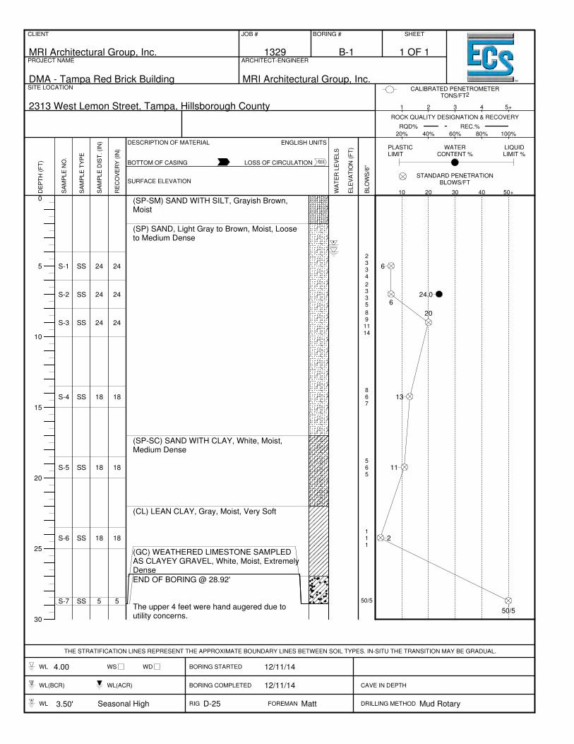
EXPLORATION RESULTS Soil Conditions Subsurface conditions within the project site were evaluated with two soil test borings. Boring B-1 was performed within the proposed addition footprint and extended to a depth of 30 feet below ground surface. Boring B-2 was performed within the pavement area and was extended to a depth of 10 feet below ground surface. The approximate boring locations are shown on the Boring Location Plan in the Appendix of this report. In general, the soils encountered consisted of sand with silt (SP-SM) to a depth of 2 feet below ground surface, fine sand (SP) to a depth of 17 feet below ground surface, sand with clay (SP-SC) to a depth of 22 feet below ground surface, and lean clay (CL) to a depth of 27 feet below ground surface. Boring B-1 encountered weathered limestone at a depth of approximately 27 feet below existing grade to the boring termination depth. SPT N-values ranged from 6 blows per foot to 50 blows with 5 inches of sampler penetration, indicating a relative density of loose to extremely dense for the cohesionless soils and medium stiff to very hard for the cohesive soils. For more detailed boring information, please see the attached boring logs located in the Appendix of this report. Groundwater Observations On the basis of depth to water measurements made in the open boreholes, we estimate that the groundwater level was encountered at a depth of approximately 4 feet below the existing ground surface at the time of drilling. The groundwater will fluctuate seasonally depending upon local rainfall. The rainy season in Central Florida is normally between June and September. Based upon our site specific field data and our experience in the area, we estimate the seasonal high groundwater levels to be about 0.5 feet above the encountered water level at the boring locations. Variations in the location of the long-term water table may occur as a result of changes in precipitation, evaporation, surface water runoff, and other factors not apparent at the time of this exploration. Existing Foundation ECS performed one test pit located at the southwest corner of the existing building to expose the existing foundation. The existing foundation measured approximately 13 inches thick and extended approximately 14.5 inches from the wall of the building.

DMA – Tampa Red Brick Building ECS Job No.: 41-1329 January 7, 2015 Page 5 of 11
ANALYSES AND RECOMMENDATIONS The recommendations presented in this report are based on the project information provided to us, the results of the soil test borings, and the engineering analyses. Considering the results of our field exploration, and our experience with similar projects, it is our judgment that the proposed construction may be supported on a shallow foundation system consisting of spread footings. The existing on-site soils are considered to be suitable for the support of the building slab on grade, provided that the subgrade soils have been properly prepared, as described in this report, and approved by the Geotechnical Engineer or their authorized representative. Foundation
According to the test borings and assumed floor grades for the proposed building, the materials anticipated at normal footing depths below the proposed floor slab should consist of Sand (SP) soils. Based on the results of the subsurface exploration, our recommendations outlined in the "Earthwork Operations" section, and our engineering analysis, we recommend that the proposed building be supported on spread footing foundations or a monolithic foundation. Structural information was not available at the time of the report preparation; however, we have assumed that the new building will be relatively lightly loaded with maximum column loads on the order of 30 kips or less and wall loads of 3 kips per lineal foot. The geotechnical analyses of the test boring data indicate the sand soils expected at subgrade levels should be suitable for a recommended allowable bearing pressure of 2,500 psf as long as they are prepared as recommended within the earthwork operations section of this report. The net allowable soil bearing pressure refers to that pressure which may be transmitted to the foundation bearing soils in excess of the final minimum surrounding overburdened pressure. Exposure to the environment may weaken the soils at the footing bearing level if the foundation excavations remain open for too long a time. Therefore, foundation concrete should be placed the same day that excavations are made. If the bearing soils are softened by surface water intrusion or exposure, the softened soils must be removed from the foundation excavation bottom immediately prior to placement of concrete. If the excavation must remain open overnight, or if rainfall becomes imminent while the soils are exposed, we recommend that a 1 inch to 3 inch thick “mud mat” of “lean” concrete be placed on the bearing soils before the placement of reinforcing steel. Settlement of individual footings designed in accordance to recommendations outlined above is expected to be small and within tolerable limits for the proposed structure. Within the proposed building, total settlements of less than 1 inch are anticipated with differential settlements per 30 foot of wall footing expected to be on the order of ½ inch or less. These settlement estimates are based on our engineering experience with these soils and are provided to guide the structural engineer with their design. Our settlement analysis assumes the soils from the bottom of the footings to a depth of 3 feet have been compacted prior to placing concrete in the footings. As such, we recommend this zone be compacted to at least 95 percent of the maximum dry density, as determined by the Modified Proctor Compaction Test (ASTM D-1557). Generally, the moisture content of the sub-footing soils should be maintained within 2 percentage points of the optimum moisture content for the fill material, as determined by ASTM D-1557. One compliance compaction test should

DMA – Tampa Red Brick Building ECS Job No.: 41-1329 January 7, 2015 Page 6 of 11
be performed at least every 2,000 square feet per foot of assumed improvement. We recommend that continuous footings have a minimum width of 1½ feet and that isolated column footings have a minimum lateral dimension of 2½ feet. The minimum dimensions recommended above help reduce the possibility of foundation bearing failure and excessive settlement due to local shear or "punching" action. All continuous load-bearing wall foundations should be suitably reinforced. To provide continuity and reduce the effects of differential settlements, the longitudinal reinforcing steel should be extended into any column footings situated along the wall footings and the foundations should be constructed as a continuous unit through monolithic concrete placement to the greatest extent practical. The reinforcing steel also should be continuous through the building corners. Where top and bottom steel is included in the continuous wall foundations, a minimum footing thickness of 1 foot should be provided. Prior to the placement of any foundation concrete, the steel reinforcement should be observed to document that the bars are properly sized and positioned in accordance with the foundation plans and specifications. Floor Slab Design
According to the test borings and recommendations included in this report, soils at the floor slab subgrade should consist of firm Sand (SP) soils or newly placed engineered fill, which should be suitable for floor slab support. The subgrade should be prepared in accordance with our recommendations outlined in the section entitled "Earthwork Operations". The slabs can then be designed as slab on grade with a modulus of subgrade reaction of 120 pci. Earthwork Operations
Subgrade Preparation
The existing ground surface in the proposed structural areas should be stripped of all construction debris, vegetation, rootmat, topsoil, and any other soft or unsuitable material from the proposed building area. The stripping within the proposed building area should be extended at least 5 feet, where possible, beyond the planned limits. The footing locations should be undercut to a depth of 3 feet below finished grade and the soils may be reused and recompacted in accordance with the section of this report entitled “Fill Placement.” After stripping to the desired grade and prior to fill placement, the exposed soils should be observed by an experience Geotechnical Engineer, or their authorized representative. The building pad of the proposed addition should be rolled multiple times in the parallel and perpendicular directions with a smooth drum roller with a minimum capacity of 10 tons. Once this operation is completed proofrolling using a loaded dump truck, having an axle weight of at least 10 tons, may be used to aid in identifying localized soft or unsuitable material which should be removed and replaced with an approved engineered fill compacted to the criteria given below in the section entitled “Fill Placement”. Fill Placement
Any fill to be placed on site should consist of soils classified SP per ASTM D-2487 and have less than 5 percent passing the No. 200 sieve. The upper 2 feet to 12 feet of the on-site soils
DMA – Tampa Red Brick Building ECS Job No.: 41-1329 January 7, 2015 Page 7 of 11
should be suitable for reuse as compacted fill, provided that the natural moisture content is within an acceptable range to obtain compaction. Clayey sand (SC) soils identified within 2 feet of pavement subgrade or finished floor elevation should be observed by the geotechnical engineer of record for acceptance and preparation recommendations. Possible mixing with onsite clean sands may be required to control plasticity and moisture content of any encountered clayey sands. Structural fill should be placed in loose lifts, which do not exceed 12 inches in thickness, and should be compacted to at least 95 percent of the maximum dry density, as determined by the Modified Proctor Compaction Test (ASTM D-1557). Generally, the moisture content of the fill materials should be maintained between 2 % below to the optimum moisture content for the fill material, as determined by ASTM D-1557. Fill placed in non-structural areas (e.g. grassed areas) should be compacted to at least 90% of the maximum dry density according to ASTM D-1557, in order to avoid significant subsidence. Compliance tests should be performed at a rate of 1 test per 2,000 square feet per foot of improvement (depth) in the structures areas and 1 test per 5,000 square feet in paved areas. If any problems are encountered during the earthwork operations, or if site conditions deviate from those encountered during our subsurface exploration, the Geotechnical Engineer should be notified immediately.
Borrow Suitability
1) Fine sand (SP) can be utilized as structural and pavement subgrade fill material
provided that the natural moisture content is within a desirable range to obtain compaction.
2) Fine sand with silt (SP-SM) and silty sand (SM) can be utilized as structural and pavement subgrade fill material provided that the natural moisture content is within a desirable range to obtain compaction. It should be noted that due to higher fine content, soil may be more sensitive to moisture and may require more handling.
3) Clayey fine sand (SC) is more difficult to use as fill, because they are more moisture sensitive. These soils may be utilized under the building and pavement areas with a minimum of 2 feet separation and a topping of fine sand (SP) over the silty/clayey soils.
Pavement Considerations
Our scope of services did not include extensive sampling and LBR testing of existing subgrade or potential sources of imported fill for the specific purpose of a detailed pavement analysis. Instead, we have assumed pavement-related design parameters that are considered to be typical for the area soil types. The recommended pavement thicknesses presented in this report section are considered typical and minimum for the assumed parameters in the general site area. We understand that budgetary considerations sometimes warrant thinner pavement sections than those presented. However, the client, the owner, and the project designers should be aware that thinner pavement sections may result in increased maintenance costs and lower than anticipated pavement life. We recommend the following pavement section designs:
DMA – Tampa Red Brick Building ECS Job No.: 41-1329 January 7, 2015 Page 8 of 11
Flexible Pavement Standard-Duty Section:
• 2.0 inches asphaltic concrete surface course (FDOT Type S-1 or S-3)
• 8 inches base course
• 12 inches stabilized subgrade
Rigid Pavement Light-Duty Section:
• 5 inches Portland cement concrete
• 12 inches of compacted, well-draining granular subgrade Subgrade All pavement subgrades should be prepared in accordance with the recommendations presented in the section entitled Earthwork Operations. In areas where Portland cement concrete pavement is planned, the concrete should be placed upon a minimum of 12 inches of compacted, free draining material and compacted to 98% of the Modified Proctor maximum dry density (ASTM D-1557). In areas where asphaltic concrete pavements are used, we suggest stabilizing the subgrade materials to a minimum Florida Bearing Value (FBV) of 75 pounds per square inch (psi). As an alternate for the FBV, materials can have a Limerock Bearing Ratio (LBR) of 40 percent. All stabilized subgrade materials should be compacted to 98 percent of the Modified Proctor (ASTM D-1557) maximum dry density and meet specification requirements for Type B or Type C Stabilized Subgrade by the Florida Department of Transportation (FDOT). The stabilized subgrade may consist of imported material or a blend of on-site soils and imported materials. If a blend is proposed, we recommend that the contractor perform a mix design to find the optimum mix proportions. Base Course Based on the observed water table as identified in the borings, ECS recommends that the base course be limerock. Limerock should have a minimum LBR of 150 percent and should be mined from an FDOT approved source. Place limerock in maximum 6-inch lifts and compact each lift to a minimum density of 98 percent of the Modified Proctor maximum dry density. If the client elects to use crushed concrete as the base material, it should follow the FDOT specification for material qualifications and placement. Place crushed concrete base in maximum 6-inch lifts and compact to a minimum density of 98 percent of the Modified Proctor maximum dry density according to specification in ASTM D-1557. Perform compliance testing for the base course to a depth of 1 foot at a frequency of one test per 5,000 square feet, or at a minimum of two test locations, whichever is greater. Effects of Groundwater One of the most critical influences on the pavement performance in Northern Florida is the relationship between the pavement subgrade and the seasonal high groundwater level. Many

DMA – Tampa Red Brick Building ECS Job No.: 41-1329 January 7, 2015 Page 9 of 11
roadways and parking areas have been destroyed as a result of deterioration of the base and the base/surface course bond. Regardless of the type of base selected, we recommend that the seasonal high groundwater and the bottom of the base course be separated by at least 12 inches for crushed concrete and 24 inches for limerock. Landscape Drains and Curbing If needed, where landscaped sections are located adjacent to parking lots or driveways, we recommend that drains be installed around these landscaped sections to protect the asphalt pavement from excess rainfall and over irrigation. Migration of irrigation water from the landscape areas to the interface between the asphalt and the base usually occurs unless landscape drains are installed. This migration often causes separation of the wearing surface from the base and subsequent rippling and pavement deterioration. The underdrains or strip drains should be routed to a positive outfall at the pavement area catch basins. Curbing around landscaped sections adjacent to parking lots and driveways should be constructed with full-depth curb sections. Using extended curb sections which lie directly on top of the final asphalt level, or eliminating curbing entirely, can allow migration of irrigation water from the landscaped areas to the interface between the asphalt and the base. This migration often causes separation of the wearing surface from the base and subsequent rippling and pavement deterioration. Geoenvironmental Concerns The equipment, techniques, and personnel used to perform a geoenvironmental study differ significantly from those used to perform a geotechnical study. For that reason, a geotechnical engineering report does not usually relate any geoenvironmental findings, conclusions, or recommendations; e.g., about the likelihood of encountering underground storage tanks or regulated contaminants. Unanticipated environmental problems have led to numerous project failures. If you have not already obtained your own geoenvironmental information, ECS would be pleased to assist with these services. ECS recommends that you not rely on reports prepared for someone else. Construction Considerations Exposure to the environment may weaken the soils at the footing bearing level if the foundation excavations remain open for too long a time. Therefore, foundation concrete should be placed the same day that excavations are dug during the rainy season or if rain is anticipated. If the bearing soils are softened by surface water intrusion or exposure, the softened soils must be removed from the foundation excavation bottom immediately prior to placement of concrete. If the excavation must remain open overnight, or if rainfall becomes imminent while the bearing soils are exposed, we recommend that a 1-inch to 3-inch thick "mud-mat" of "lean" concrete be placed on the bearing soils before the placement of reinforcing steel. Proper compaction of controlled fill is an important aspect of this project. Therefore, we recommend that all fill operations be observed on a full-time basis by a qualified soil technician to determine if minimum compaction requirements are being met.

DMA – Tampa Red Brick Building ECS Job No.: 41-1329 January 7, 2015 Page 10 of 11
The surficial soils contain fines which are considered moderately erodible. The Contractor should provide and maintain good site drainage during earthwork operations to help maintain the integrity of the surface soils. The surface of the site should be kept properly graded in order to enhance drainage of the surface water away from the proposed construction areas during the earthwork phase. We recommend that surface drainage be diverted around the proposed structural area without significantly interrupting its pattern. All erosion and sedimentation shall be controlled in accordance with sound engineering practice and current state and local requirements. In a dry and undisturbed state, the upper 1 foot of the majority of the soil at the site will provide good subgrade support for fill placement and construction operations. However, when wet, these soils will degrade quickly with disturbance from contractor operations. Therefore, good site drainage should be maintained during earthwork operations, which will help maintain the integrity of the soil. Report Limitations This report has been prepared to aid in the evaluation of this site and to assist the design team with the design of the proposed facility. The report scope is limited to this specific project and the location described. The project description represents our current understanding of the significant aspects of the proposed improvements relevant to the geotechnical considerations. Site exploration identifies subsurface conditions only at those points where subsurface tests are conducted or samples are taken. ECS reviewed field and laboratory data and then applied professional judgment to render an opinion about subsurface conditions throughout the site. Actual subsurface conditions may differ – sometimes significantly – from those indicated in this report. Retaining ECS to provide construction observation is one of the most effective methods of managing the risks associated with unanticipated conditions. The analysis and recommendations are, of necessity, based on the information made available to us at the time of the actual writing of the report and the on-site conditions, surface and subsurface that existed at the time the exploratory borings were drilled. Further assumptions have been made that the limited exploratory borings, in relation both to the aerial extent of the site and to depth, are representative of conditions across the site. If subsurface conditions are encountered which differ significantly from those reported herein, this office should be notified immediately so that the analyses and recommendations can be reviewed for validity. A geotechnical engineering report is based upon conditions that existed at the time the study was performed. Do not rely on this report if the adequacy may have been affected by: passage of time; by man-made events, such as construction on or adjacent to the site; or by natural events such as floods, hurricanes, or groundwater fluctuations. Always contact ECS before applying the report to determine if it is still reliable. A minor amount of additional testing or analysis could prevent major problems. Geotechnical engineers consider a number of unique, project-specific factors when establishing the scope of study. Typical factors include: the client’s goals, objectives, and risk management preferences; the nature of the structure involved, its size, and configuration; the location of the structure on site; and other planned or existing site improvements, such as access roads, parking lots, underground utilities. Unless ECS indicates otherwise, do not rely on this report if it was not prepared for you; not prepared for your
DMA – Tampa Red Brick Building ECS Job No.: 41-1329 January 7, 2015 Page 11 of 11
project; not prepared for the specific site explored; or completed before important project changes were made. Typical changes that can erode the reliability of an existing geotechnical engineering report include those that effect: the function of the proposed structure; elevation, configuration, location, orientation, or weight of the proposed structure; composition of the design team; or project ownership. As a general rule, always inform ECS of project changes – even minor ones – and request an assessment of their impact. ECS cannot accept responsibility or liability for problems that occur because our report does not consider developments of which we were not informed. The report was designed to meet the specific needs that we have discussed. This report should not be relied upon to fulfill the needs of contractors. No one should rely on this report without first consulting with ECS. Furthermore, no one should apply this report for any purpose or project except the one originally contemplated. ECS recommends that the complete geotechnical report be provided to contractors, but that it should be prefaced with a clearly written letter of transmittal. In that letter, advise contractors that the report was not prepared for purposes of bid development and that the report’s accuracy is limited. We recommend that the contractor retain ECS to conduct additional study to obtain the specific types of information they need or prefer. A pre-bid conference may also be valuable. Be sure contractors have sufficient time to perform additional study. Only then might you be in a position to give contractors the available information, while requiring them to at least share some of the financial responsibilities stemming from unanticipated conditions. Do not over rely on the construction recommendations included in this report. These recommendations are not final. We can finalize our recommendations only by observing actual subsurface conditions revealed during construction. The placement of any new engineered fill will require adequate monitoring during construction in order to confirm that the fill mass is installed properly to avoid future settlements. Because of our in-depth knowledge of the subsurface conditions at the site, we recommend that ECS observe all earthwork and construction operations to confirm that the work is being performed in accordance with the project specifications. It is also recommended that ECS be allowed to prepare or at least review the project specifications with regard to the earthwork for this site. ECS cannot assume responsibility or liability if we do not perform full-time construction observation during earthwork operations and foundation installation. Closing We would appreciate the opportunity to continue our involvement on the project during construction. ECS-Florida, LLC would appreciate the opportunity to offer our construction materials testing, threshold inspections, and facilities engineering services.

.
APPENDIX
Unified Soil Classification System Reference Notes for Boring Logs Boring Logs B-1 and B-2 Laboratory Testing Summary
Boring Location Plan

0
10
20
30
40
50
60
70
80
0 10 20 30 40 50 60 70 80 90 100 110
CL-ML
CL or OL
CH or OH
MH or OH
ML or OL
"A" LINE
LIQUID LIMIT, LL
UNIFIED SOIL
CLASSIFICATION
SYSTEM
Unified Soil Classification System
(ASTM Designation D-2487)
Major Division Group Symbol
GW
GP
GM
GC
SW
SP
SM
SC
ML
CL
OL
MH
CH
OH
Pt
Typical Names
Well-graded gravels and gravel-
sand mixtures, little or no fines
Poorly graded gravels and gravel-
sand mixtures, little or no fines
Silty gravels, gravel-sand-silt
mixtures
Clayey gravels, gravel-sand-clay
mixtures
Well-graded sands and gravelly
sands, little or no fines
Poorly graded sands and gravelly
sands, little or no fines
Silty sands, sand-silt mixtures
Clayey sands, sand-clay mixtures
Inorganic silts, very fine sands,
rock flour, silty or clayey fine
sands
Inorganic clays of low to medium
plasticity, gravelly clays, sandy
clays, silty clays, lean clays
Organic silts and organic silty
clays of low plasticity
Inorganic silts, micaceous or
diatomaceous fine sands or silts,
elastic silts
Inorganic clays of high plasticity,
fat clays
Organic clays of medium to high
plasticity
Peat, muck and other highly
organic soils
Classification Criteria
Cu = D60/D10 Greater than 4
Cz = (D30)2/(D10xD60) Between 1 and 3
Not meeting both criteria for GW
Atterberg limits plot below “A” line or
plasticity index less than 4
Atterberg limits plot above “A” line
and plasticity index greater than 7
Cu = D60/D10 Greater than 6
Cz = (D30)2/(D10xD60) Between 1 and 3
Not meeting both criteria for SW
Atterberg limits plot below “A” line or
plasticity index less than 4
Atterberg limits plot above “A” line
and plasticity index greater than 7
Highly organic soils
Co
arse
-gra
ined
soil
s
Mo
re t
han
50
% r
etai
ned
on
No
. 20
0 s
ieve
Fin
e-gra
ined
so
ils
50
% o
r m
ore
pas
sin
g N
o.
20
0 s
ieve
San
ds
More
th
an 5
0%
of
coar
se
frac
tion
pas
ses
No. 4
sie
ve
Gra
vel
s
More
th
an 5
0%
of
coar
se
frac
tion
ret
ain
ed o
n N
o. 4
sie
ve
Sil
ts a
nd
Cla
ys
Liq
uid
lim
it
gre
ater
than
50%
Sil
ts a
nd
Cla
ys
Liq
uid
lim
it
50%
or
less
Cla
ssif
icat
ion o
n b
asis
of
per
cen
tage
of
fin
es
GW
, G
P,
SW
, S
P
GM
, G
C,
SM
, S
C
Bord
erli
ne
clas
sifi
cati
on
req
uir
ing u
se o
f dual
sym
bo
l
Les
s th
an 5
% P
ass
No. 2
00 s
ieve
More
th
an 1
2%
Pas
s N
o. 200 s
ieve
5%
to 1
2%
Pas
s N
o. 200
sie
ve
Fibrous organic matter; will
char, burn, or glow
Plasticity chart for the classification of fine-grained soils.
Tests made on fraction finer than No. 40 sieve
“U” LINE
Note: U-line represents approximate upper limit of LL and PI combinations
for natural soils (empirically determined). ASTM-D2487.

REFERENCE NOTES FOR BORING LOGS I. Drilling Sampling Symbols:
SS Split Spoon Sampler ST Shelby Tube Sampler RC Rock Core, NX, BX, AX PM Pressuremeter DC Dutch Cone Penetrometer RD Rock Bit Drilling BS Bulk Sample of Cuttings PA Power Auger (no sample) HAS Hollow Stem Auger WS Wash Sample
II. Correlation of Penetration Resistances to Soil Properties:
Standard Penetration (Blows/Ft) refers to the blows per foot of a 140 lb. Hammer falling 30 inches on a 2-inch OD split spoon sampler, as specified in ASTM D-1586. The blow count is commonly referred to as the N value. A. Non-Cohesive Soils (Silt, Sand, Gravel and Combinations)
Density Relative Properties Under 4 blows/ft Very Loose Adjective Form 12% to 49% 4 to 10 blows/ft Loose With 5% to 12% 11 to 30 blows/ft Medium Dense 31 to 50 blows/ft Dense Over 51 blows/ft Very Dense
Particle Size Identification Boulders 8 inches or larger Cobbles 3 to 8 inches Gravel Coarse 1 to 3 inches Medium ½ to 1 inch Fine ¼ to ½ inch Sand Coarse 2.00 mm to ¼ inch (dia. of lead pencil) Medium 0.42 to 2.00 mm (dia. of broom straw) Fine 0.074 to 0.42 mm (dia. of human hair) Silt and Clay 0.0 to 0.074 mm (particles cannot be seen)
B. Cohesive Soils (Clay, Silt, and Combinations)
Blows/ft Consistency
Unconfined Comp. Strength
Qp (tsf)
Degree of Plasticity
Plasticity Index
Under 2 Very Soft Under 0.25 None to Slight 0 – 4 2 to 4 Soft 0.25-0.49 Slight 5 -7 4 to 8 Med. Stiff 0.50-0.99 Medium 8 - 22
9 to 15 Stiff 1.00-1.99 High to Very High
Over 22
16 to 30 Very Stiff 2.00-3.00 Over 30 Hard Over 4.00

III. Water Level Measurement Symbols:
WL Water Level BCR Before Casing Removal DCI Dry Cave-In WS While Sampling ACR After Casing Removal WCI Wet Cave-In WD While Drilling Existing Groundwater Level ● Est. Seasonal High
GWT The water levels are those water levels actually measured in the borehole at the times indicated by the symbol. The measurements are relatively reliable when augering, without adding fluids, in a granular soil. In clay and plastic silts, the accurate determination of water levels may require several days for the water level to stabilize. In such cases, additional methods of measurement are generally applied.
0
5
10
15
20
25
30
S-1
S-2
S-3
S-4
S-5
S-6
S-7
SS
SS
SS
SS
SS
SS
SS
24
24
24
18
18
18
5
24
24
24
18
18
18
5
(SP-SM) SAND WITH SILT, Grayish Brown,Moist
(SP) SAND, Light Gray to Brown, Moist, Looseto Medium Dense
(SP-SC) SAND WITH CLAY, White, Moist,Medium Dense
(CL) LEAN CLAY, Gray, Moist, Very Soft
(GC) WEATHERED LIMESTONE SAMPLEDAS CLAYEY GRAVEL, White, Moist, ExtremelyDense
END OF BORING @ 28.92'
The upper 4 feet were hand augered due toutility concerns.
2334
2335
89
1114
867
565
111
50/5
6
624.0
20
13
11
2
50/5
CLIENT
MRI Architectural Group, Inc.
JOB #
1329
BORING #
B-1
SHEET
PROJECT NAME
DMA - Tampa Red Brick Building
ARCHITECT-ENGINEER
MRI Architectural Group, Inc.SITE LOCATION
2313 West Lemon Street, Tampa, Hillsborough County
THE STRATIFICATION LINES REPRESENT THE APPROXIMATE BOUNDARY LINES BETWEEN SOIL TYPES. IN-SITU THE TRANSITION MAY BE GRADUAL.
WL 4.00 WS WD BORING STARTED 12/11/14
WL(BCR) WL(ACR) BORING COMPLETED 12/11/14 CAVE IN DEPTH
WL 3.50' Seasonal High RIG D-25 FOREMAN Matt DRILLING METHOD Mud Rotary
DE
PT
H (
FT
)
SA
MP
LE
NO
.
SA
MP
LE
TY
PE
SA
MP
LE
DIS
T. (I
N)
RE
CO
VE
RY
(IN
)
SURFACE ELEVATION
DESCRIPTION OF MATERIAL
WA
TE
R L
EV
ELS
ELE
VA
TIO
N (
FT
)
BLO
WS
/6"
10 20 30 40 50+
20% 40% 60% 80% 100%
1 2 3 4 5+
ENGLISH UNITS
BOTTOM OF CASING LOSS OF CIRCULATION
CALIBRATED PENETROMETERTONS/FT2
PLASTICLIMIT
WATERCONTENT %
LIQUIDLIMIT %
ROCK QUALITY DESIGNATION & RECOVERY
RQD% REC.%
STANDARD PENETRATIONBLOWS/FT
1 OF 1

0
5
10
15
20
25
30
S-1
S-2
S-3
S-4
S-5
SS
SS
SS
SS
SS
24
24
24
24
24
24
24
24
24
24
Asphalt Depth [1"], ABC Stone Depth [3"]
(SP) SAND, Gray to Brown, Moist, Loose toMedium Dense
END OF BORING @ 10.00'
13665
7886
5559
68
1312
9101816
12
16
10
21
28
CLIENT
MRI Architectural Group, Inc.
JOB #
1329
BORING #
B-2
SHEET
PROJECT NAME
DMA - Tampa Red Brick Building
ARCHITECT-ENGINEER
MRI Architectural Group, Inc.SITE LOCATION
2313 West Lemon Street, Tampa, Hillsborough County
THE STRATIFICATION LINES REPRESENT THE APPROXIMATE BOUNDARY LINES BETWEEN SOIL TYPES. IN-SITU THE TRANSITION MAY BE GRADUAL.
WL 4.00 WS WD BORING STARTED 12/11/14
WL(BCR) WL(ACR) BORING COMPLETED 12/11/14 CAVE IN DEPTH
WL RIG D-25 FOREMAN Matt DRILLING METHOD Mud Rotary
DE
PT
H (
FT
)
SA
MP
LE
NO
.
SA
MP
LE
TY
PE
SA
MP
LE
DIS
T. (I
N)
RE
CO
VE
RY
(IN
)
SURFACE ELEVATION
DESCRIPTION OF MATERIAL
WA
TE
R L
EV
ELS
ELE
VA
TIO
N (
FT
)
BLO
WS
/6"
10 20 30 40 50+
20% 40% 60% 80% 100%
1 2 3 4 5+
ENGLISH UNITS
BOTTOM OF CASING LOSS OF CIRCULATION
CALIBRATED PENETROMETERTONS/FT2
PLASTICLIMIT
WATERCONTENT %
LIQUIDLIMIT %
ROCK QUALITY DESIGNATION & RECOVERY
RQD% REC.%
STANDARD PENETRATIONBLOWS/FT
1 OF 1

B-1
S-2 6.00 - 8.00 24.0 SP 3.6
Laboratory Testing Summary
Notes: 1. ASTM D 2216, 2. ASTM D 2487, 3. ASTM D 4318, 4. ASTM D 1140, 5. See test reports for test method, 6. See test reports for test method
Definitions: MC: Moisture Content, Soil Type: USCS (Unified Soil Classification System), LL: Liquid Limit, PL: Plastic Limit, PI: Plasticity Index, CBR: California Bearing Ratio, OC: Organic Content (ASTM D 2974)
Project No. 1329ECS Florida, LLC
Project Name: DMA - Tampa Red Brick Building
PM: Chris Egan
PE: Miguel A. SantiagoTampa, FL
Printed On: Thursday, December 18, 2014
SampleSource
SampleNumber
Depth(feet)
MC1
(%)Soil
Type2 LL
Atterberg Limits3
PL PI
PercentPassingNo. 200Sieve4
MaximumDensity
(pcf)
Moisture - Density (Corr.)5
OptimumMoisture
(%)
CBRValue6 Other
Page 1 of 1

DMA - Tampa Red Brick Building
Section 23, Township 29 South, Range 18 East 2313 West Lemon Street, Tampa, Florida
Figure 1 Boring Location Plan
@A
@A
B-2
B-1
\0 9045
FeetECS No. 41-1329
NOTES:Aerial photograph courtesy of FloridaState University.