REPORT OF GEOTECHNICAL EXPLORATION...
47
REPORT OF GEOTECHNICAL EXPLORATION PUBLIC WORKS SITE SAVANNAH, GEORGIA FOR CHATHAM CO. DEPT. OF PUBLIC WORKS & PARK SERVICES MAY 5, 2009 ECS PROJECT NO. 23:2081
Transcript of REPORT OF GEOTECHNICAL EXPLORATION...

REPORT OF GEOTECHNICAL EXPLORATION PUBLIC WORKS SITE SAVANNAH, GEORGIA
FOR CHATHAM CO. DEPT. OF PUBLIC WORKS & PARK
SERVICES
MAY 5, 2009 ECS PROJECT NO. 23:2081
i. - -- ~", " -. _. , I
~~ ECS SOUTHEAST, LLCr -- - ~ Geotechnical- Construction Materials - Environmental- Facilities
May 5, 2009Mr. Robert DrewryChatham Co. Dept. of Public Works & Park ServicesP.O. Box 8161
Savannah, GA 31412
Reference: Report of Geotechnical ExplorationPublic Works Site
Savannah, GeorgiaECS Project No. 23:2081
Dear Mr. Drewry:
ECS Southeast, LLC (ECS) is pleased to submit our report of geotechnical exploration for theabove referenced project. The attached report presents an introduction of the proposedproject, results of our exploration, subsurface conditions, and our recommendations. The workwas completed in general accordance with our Proposal No. PSG-1855 as authorized byPurchase Order 00212663.
We appreciate the opportunity of working with you on this project and look forward to ourcontinued association. Should you have questions regarding our findings or need additionalconsultations, please do not hesitate to contact our office at (912) 966-2527.
Respectfully,
ECS Southeast, LLC represented by:
David B. Bradley, P.G.Geotechnical Department Manager
~geGeotechnical Project Manager
1306Heidt Avenue, Suite A, Savannah, GA 31408. (912) 966-2527. FAX (912) 966-9931. www.ecslimited.comAtlanta, GA - Bluff ton - Hilton Head, SC* - Buford, GA - Nashville, TN - Savannah, GA
*testing services only

REPORT OF GEOTECHNICAL EXPLORATION
PUBLIC WORKS SITE SAVANNAH, GEORGIA TABLE OF CONTENTS
PAGE INTRODUCTION 2
General 2 Project Information 2 Site Conditions 2 Purposes of Exploration 2
FIELD AND LABORATORY EXPLORATION 2
Subsurface Exploration 2 Laboratory Testing Program 3
SUBSURFACE CONDITIONS 3
Regional Geology and Soils 3 Soil Conditions 4 Groundwater Conditions 5
EVALUATIONS AND RECOMMENDATIONS 5
General 5 Dewatering 6 Subgrade Preparation 6 Recommended Earthwork Specifications 7 Foundation Recommendations 8 Seismic Parameters 8 Additional Considerations 10
CLOSING 11
APPENDIX
I. Figure 1 – Site Vicinity Map Figure 2 – Boring Location Plan
II. Unified Soil Classification System
Reference Notes for CPT Soundings Reference Notes for Boring Logs CPT Sounding Logs (7) Hand Auger Logs (8) Geoprobe Logs (1) Laboratory Testing Summary Liquefaction Analysis
Seismic Hazard Deaggregation
III. ASFE – Important Information About Your Geotechnical Report

INTRODUCTION
General This report presents the results of our geotechnical exploration for the Public Works Site project in Savannah, Chatham County, Georgia. The work was completed in general accordance with our Proposal No. PSG-1855 as authorized by Purchase Order 00212663. Project Information The information presented in this report is based on our site reconnaissance and our understanding of the proposed project. If the information in this section is incorrect or changes, the applicability of the report should be reviewed. Based on plans provided of the proposed project and conversations with the project team we understand the following:
• The site is located off Varnedoe Road in Savannah, Chatham County, Georgia. A site
vicinity map is included in the Appendix as Figure 1. • The proposed project consists of the construction of three single story buildings (an
administration, field services, and vehicular storage building) with associated infrastructure and parking.
• No loading information has been provided. We have assumed maximum isolated interior column loads will not exceed 30 kips and that maximum wall loads will not exceed 3 kips per linear foot.
• No grading information has been provided. We have assumed minimal fill will be required to bring the site to finished construction grade.
Site Conditions The existing ground elevation of the site is approximately 20 feet above mean sea level (MSL). A representative of ECS visited the project site on April 24, 2009. The site was developed with an existing gym and stadium. There was evidence of transients inhabiting the site near HA-5 and HA-6 in the form of a tent, clothes, and recently used bottles and plates. The upland area landscape was relatively flat. Standing water was observed in the vicinity of HA-5 and HA-6 at the time of our visit. The site is bordered to the west by Varnedoe Drive and to the north by Scott Drive. Asphalt, apparently from a previously existing roadway, was observed at the surface in the vicinity of HA-3. Purposes of Exploration The purposes of this study were to explore the soil and groundwater conditions at the site and to develop engineering recommendations to guide design of the proposed project.

Public Works Site ECS Project No. 23:2081 Page 2
We accomplished the purposes of the study by:
1. Reviewing the available publications concerning local geology of the site and performing a general site reconnaissance;
2. Drilling borings/soundings to explore the subsurface soil and groundwater
conditions;
3. Performing laboratory tests on selected representative soil samples from the borings to evaluate pertinent engineering properties;
4. Evaluating the field, laboratory, and background data to develop appropriate
engineering recommendations.
FIELD AND LABORATORY EXPLORATION Subsurface Exploration To explore the soil and groundwater conditions at this site a total of seven (7) Cone Penetration Test (CPT) soundings, one (1) continuous soil sample (Geoprobe), and eight (8) hand auger borings were performed at select locations across the site. The CPT soundings were performed to termination depths of 30 to 38.5 feet below existing grade in the proposed building pad areas. The Geoprobe was performed to a depth of 20 feet below existing grade adjacent to a CPT sounding. The hand auger borings were performed to depths of 5 feet below existing grade at select CPT sounding locations and in proposed parking areas. The approximate boring/sounding locations are shown on the attached Boring Location Plan (Figure 2). All borings were located in the field based on existing site features. In the CPT sounding procedure (ASTM D5778), an electronically instrumented cone penetrometer is hydraulically advanced through the soil to measure point resistance, pore water pressure, and sleeve friction. These values are recorded continuously as the cone is pushed to the desired depth. Stratification lines on the CPT sounding logs represent approximate boundaries between soil behavior types. Soil behavior types are calculated based on empirical relationships between cone penetrometer tip resistance, sleeve friction, and pore water pressure. In the Geoprobe procedure, an acetate tube inside a thin-walled tube sampler is advanced through the soil to collect continuous five-foot section samples of the subsurface material. The acetate tubes are removed from the thin-wall sampler and logged. Representative samples are sealed and returned to our laboratory in Savannah, Georgia. The hand auger borings were conducted in general accordance with ASTM Specification D1452. In this procedure, the auger boring is made by rotating and advancing an auger to the desired depths while periodically removing the auger from the hole to clear and examine the

Public Works Site ECS Project No. 23:2081 Page 3
auger cuttings. Representative portions of the auger cuttings were then sealed and returned to our laboratory in Savannah, Georgia for further visual examination and laboratory testing. Stratification lines shown on the hand auger boring logs represent approximate boundaries between physical soil types. Groundwater levels in the CPT soundings were recorded during hydraulic advancement of the cone penetrometer. Groundwater levels in the hand auger borings were checked after boring completion. Laboratory Testing Program Representative soil samples were selected and tested in our laboratory to check field classifications and to determine pertinent engineering properties. The laboratory testing program included visual classifications of soil samples, natural moisture content, and wash No. 200 sieve analysis. Each soil sample was classified on the basis of visual texture and plasticity in accordance with the Unified Soil Classification System. The various soil types were grouped into the major zones noted on the boring logs. The stratification lines designating the interfaces between materials on the boring logs are approximate; in-situ, the transitions may be gradual. The soil samples will be retained in our laboratory for a period of 60 days, after which, they will be discarded unless otherwise instructed.
SUBSURFACE CONDITIONS Regional Geology and Soils The site is located within Georgia’s Coastal Plain Geologic Province. The soils of the Southern Coastal Plain Physiographic Province of Georgia are primarily composed of Pleistocene to Holocene age deposits. The soils in the coastal plain are the result of sediment deposition in a former marine environment during a time when sea level was much higher than at present. The Pleistocene-Holocene deposits are generally composed of alternating sands, silts, and clays, which correspond to fluctuations in sea-level and migrations of river channels over several million years. Based on the 1974 Soil Survey of Bryan and Chatham Counties, Georgia, as prepared by the US Department of Agriculture Soil Conservation Service, a summary of the predominant soil types (within the upper 5 feet below existing grade) at the site and their characteristics is included in the following table:

Public Works Site ECS Project No. 23:2081 Page 4
Table 1: Soil Survey Summary
The shallow groundwater table in the coastal region can fluctuate several feet with seasonal rainfall. Seasonal high groundwater levels are typically found at shallow depths in the flood plains with a reasonable probability of flooding in winter and spring. Seasonal high groundwater can be found at the surface in poorly draining areas. The groundwater table can exhibit some distortions due to differences in vertical and lateral permeability. Soil Conditions Data from the subsurface exploration is included in the Appendix. The subsurface conditions discussed in the following paragraphs and those shown on the sounding and boring logs represent an estimate of the subsurface conditions based on interpretation of the data using normally accepted geotechnical engineering judgments. We note that the transition between soil strata is usually less distinct than those shown on the sounding and boring logs. The CPT soundings conducted for this exploration recorded similar soil behavior types across the site. The soundings generally recorded layers of Sand underlain by Silty Sand and Clay soil behavior types to sounding termination depths of 30 to 38.5 feet below existing grade. A layer of fine grained material (Clay) was recorded in the CPT soundings from approximately 26 feet to sounding termination depth of 38.5 feet below existing grade. The hand auger borings encountered up to 16 inches of topsoil at the surface. Below the surficial material, the hand auger borings encountered slightly clayey Sand (SP-SC) and clayey Sand (SC) to boring termination depths of 5 feet below existing grade. The Geoprobe encountered approximately 3 inches of topsoil at the surface. Below the surficial material, the Geoprobe generally encountered slightly clayey Sand (SP-SC) to sampling termination depth of 20 feet below existing grade.
Soil Type Constituents Internal Drainage Seasonal High Water
Table (inches)
Chipley Fine Sand (Cm) Fine Sand Moderately Well Drained 24 to 36
Ellabelle Loamy Sand (El) Loamy Sand, Sandy Clay Loam Very Poorly Drained 0 to 6
Lakeland Sand (Lp) Sand Excessively Drained > 80

Public Works Site ECS Project No. 23:2081 Page 5
The generalized subsurface conditions are summarized in the following table:
Table 2: Generalized Soil Conditions
Depth (feet)
Soil Behavior Type Average qc
(tsf) Relative
Density/Consistency Geoprobe Log
(0-20 feet) USCS
Classification
0-11 Sand to Silty Sand 50-325+ Medium Dense to Very Dense Slightly Clayey SAND SP-SC
11-20 Silty Sand to Sandy Silt 50-75 Medium Dense Slightly Clayey SAND SP-SC
20-26 Silty Sand to Sandy Silt 50-200 Medium Dense to
Dense N/A N/A
26-38.5 Clay to Silty Clay 15-50 Medium Stiff to Stiff N/A N/A
Groundwater Conditions Based on pore water pressure measurements, groundwater was apparent in the CPT soundings at depths ranging from approximately 4 to 6.5 feet below existing grade at the time of sounding. Groundwater was observed in hand auger borings HA-1, HA-2, HA-4, and CPT-6 at a depth of approximately 4 feet below existing grade at the time of boring. Groundwater was observed in hand auger borings HA-5 and HA-6 at a depth of approximately 2 feet below existing grade at the time of boring. Groundwater was observed in the Geoprobe at a depth of approximately 5 feet below existing grade at the time of sampling. Please note that groundwater levels in coastal geology fluctuate with tidal, seasonal, and climatic variations, and may be significantly different at other times. The groundwater levels should be checked prior to construction to assess its effects on grading operations and other activities.
EVALUATIONS AND RECOMMENDATIONS General The following engineering recommendations are based on our understanding of the proposed construction, the data obtained in the soil test borings/soundings performed, our site reconnaissance, and our experience with soils and subsurface conditions similar to those encountered at this site. We recommend that the proposed structure be supported on conventional shallow spread or continuous footing foundations, provided the criteria in the following sections entitled “Subgrade Preparation” and “Recommended Earthwork Specifications” are met. Detailed evaluations and recommendations in the following sections should be read in full.

Public Works Site ECS Project No. 23:2081 Page 6
Dewatering Groundwater levels should be checked immediately prior to any earthwork operations. Based on groundwater levels encountered during our geotechnical exploration and our understanding of the proposed project, the potential for required dewatering operations is moderate. If groundwater is found within 3 feet of final construction grade prior to earthwork operations, remedial dewatering may be necessary. The remedial dewatering operations may consist of installing a well point system, perimeter rim ditches and, if necessary, secondary rim-ditches to withdraw groundwater. Temporary dewatering will not only help lower the natural moisture content of the subgrade soils but will also allow heavy construction equipment to gain access to portions of the site. The groundwater table should be controlled at least 3 feet below the compacted or excavated elevations. Groundwater levels may fluctuate during tidal cycles due to the site’s proximity to tidal water. Subgrade Preparation The subgrade preparation should consist of stripping all vegetation, rootmat, topsoil, and any other soft or unsuitable material from the building and pavement areas. We recommend earthwork clearing be extended a minimum of 10 feet beyond the building and 5 feet beyond pavement limits. Stripping limits should be extended an additional 1 foot for each foot of fill required at the building areas exterior edge. This would include the removal of any abandoned utilities or existing structure foundations. Depending on planned finished grades, any unsuitable existing material should be “demucked” or over-excavated as to allow for a minimum 2 foot “cushion” of suitable material in the building and pavement areas. The “cushion” is understood to extend from below the building slab granular base material (if needed), or below roadway graded aggregate base material. Unsuitable soil materials are defined as those complying with ASTM D2487 soil classification groups ML, MH, CH, CL, OL, OH and PT. Additionally, soil materials defined as those complying with ASTM D2487 soil classification groups SC or SM may be deemed unusable during subgrade evaluation due to the natural moisture content, consistency, or fines content of the material. The unsuitable or unusable material should be replaced with approved structural fill as defined in the following section “Recommended Earthwork Specifications”. After stripping, “demucking”, or over-excavating to the desired grade, and prior to fill placement, the exposed surface should be observed by an experienced geotechnical engineer or his authorized representative. For building and pavement areas, the subgrade should be densified with a large vibratory roller to achieve a uniform subgrade. In areas with minimal fill planned (less than 2 feet), the existing subgrade should consist of suitable soils such as those defined by ASTM D2487 soil classification groups GW, GP, GM, SC, SM, SW, SP-SC, and SP.

Public Works Site ECS Project No. 23:2081 Page 7
After the completion of densification, proofrolling using a loaded dump truck having an axle weight of at least 10 tons should be used to aid in identifying localized soft or unsuitable material. Any soft or unsuitable materials encountered during this proofrolling should be removed and replaced with an approved backfill compacted to the criteria given below. ECS can provide alternative options such as using geogrid and/or geotextile to stabilize the subgrade at the time of construction, if necessary. Generally, the existing surficial material onsite appears suitable as subgrade material for building pad and pavement areas. Recommended Earthwork Specifications Fill in structural areas should be placed over a stable subgrade. Soils used for structural fill shall have a PI (Plasticity Index) of less than 10, and a LL (Liquid Limit) of less than 30. The soils to be used as structural fill in the building pad areas and below the top 2 feet in pavement areas should be inorganic, non-plastic granular soil containing less than 25 percent fines passing the No. 200 sieve. The soils to be used as structural fill within the top 2 feet below pavement areas should be inorganic, non-plastic granular soil containing less than 15 percent fines passing the No. 200 sieve. The structural fill depths are understood to extend from below the building slab granular base material (if needed) or roadway graded aggregate base material. The existing surficial material generally appears suitable for re-use as structural fill in the proposed building pad and pavement areas. The structural fill should be placed in level lifts not exceeding 12 inches in loose thickness and compacted to at least 95% of the maximum dry density obtained in accordance with ASTM Specification D1557, Modified Proctor Method. Fill placed within the top 24 inches in pavement areas should be compacted to at least 98% of the maximum dry density obtained in accordance with ASTM Specification D1557, Modified Proctor Method. In-place density tests shall be performed by an experienced engineering technician working under the direction of a licensed geotechnical engineer with a minimum of 1 test per 2,500 square feet of fill area for each lift of fill placed. The elevation and location of the tests should be clearly identified and recorded at the time of fill placement. The moisture content of the fill at the time of placement shall be within +/- 3% (wet or dry) of the optimum moisture content, as determined by the appropriate proctor compaction tests. Moisture contents may be controlled by disking or other approved chemical or mechanical means to achieve the desired moisture content and density specification.
Public Works Site ECS Project No. 23:2081 Page 8
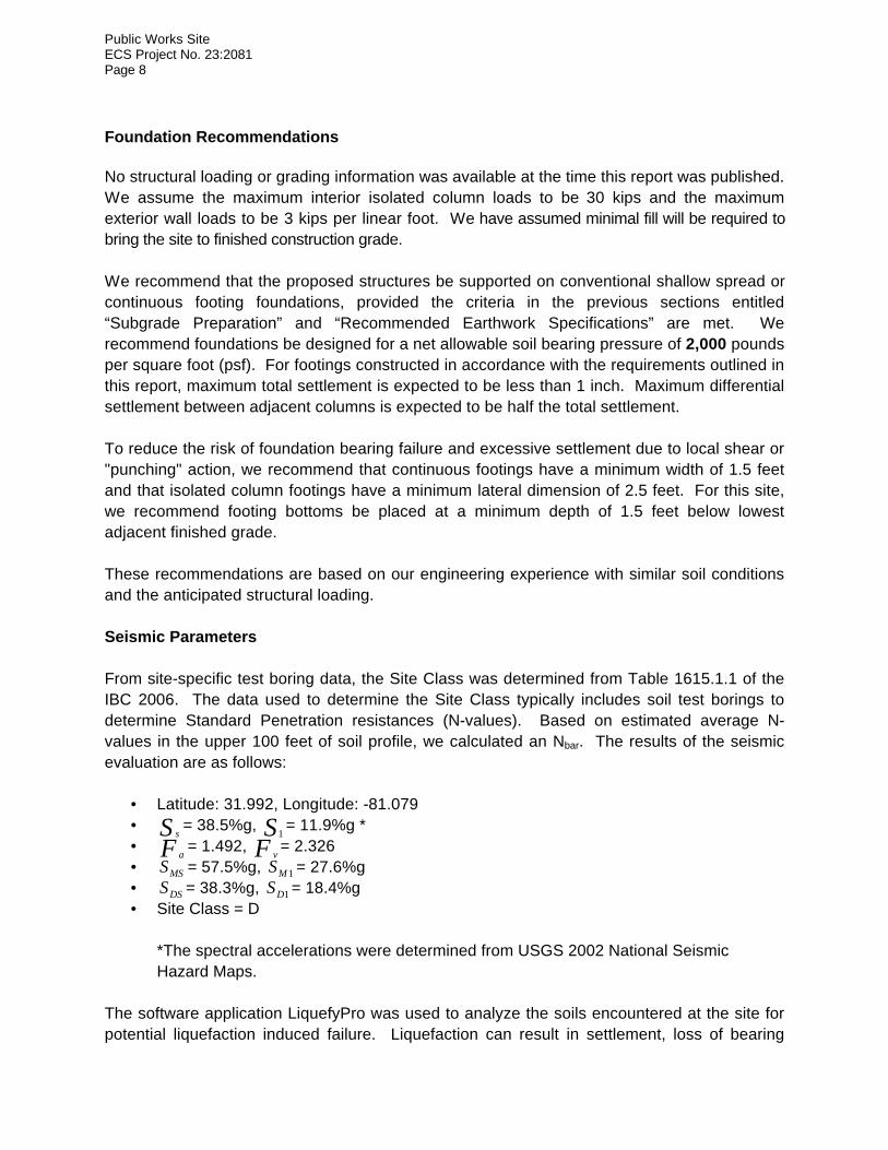
Foundation Recommendations No structural loading or grading information was available at the time this report was published. We assume the maximum interior isolated column loads to be 30 kips and the maximum exterior wall loads to be 3 kips per linear foot. We have assumed minimal fill will be required to bring the site to finished construction grade. We recommend that the proposed structures be supported on conventional shallow spread or continuous footing foundations, provided the criteria in the previous sections entitled “Subgrade Preparation” and “Recommended Earthwork Specifications” are met. We recommend foundations be designed for a net allowable soil bearing pressure of 2,000 pounds per square foot (psf). For footings constructed in accordance with the requirements outlined in this report, maximum total settlement is expected to be less than 1 inch. Maximum differential settlement between adjacent columns is expected to be half the total settlement. To reduce the risk of foundation bearing failure and excessive settlement due to local shear or "punching" action, we recommend that continuous footings have a minimum width of 1.5 feet and that isolated column footings have a minimum lateral dimension of 2.5 feet. For this site, we recommend footing bottoms be placed at a minimum depth of 1.5 feet below lowest adjacent finished grade. These recommendations are based on our engineering experience with similar soil conditions and the anticipated structural loading. Seismic Parameters From site-specific test boring data, the Site Class was determined from Table 1615.1.1 of the IBC 2006. The data used to determine the Site Class typically includes soil test borings to determine Standard Penetration resistances (N-values). Based on estimated average N-values in the upper 100 feet of soil profile, we calculated an Nbar. The results of the seismic evaluation are as follows:
• Latitude: 31.992, Longitude: -81.079 • S s = 38.5%g, S1 = 11.9%g * • F a = 1.492, F v = 2.326 • MSS = 57.5%g, 1MS = 27.6%g • DSS = 38.3%g, 1DS = 18.4%g • Site Class = D
*The spectral accelerations were determined from USGS 2002 National Seismic Hazard Maps.
The software application LiquefyPro was used to analyze the soils encountered at the site for potential liquefaction induced failure. Liquefaction can result in settlement, loss of bearing

Public Works Site ECS Project No. 23:2081 Page 9
capacity, and lateral spreading of the ground surface during earthquake induced ground motions. A liquefaction analysis was performed using site-specific probabilistic earthquake magnitude and peak ground acceleration (PGA) data obtained from the USGS and CPT sounding data obtained from our subsurface exploration. Sounding CPT-7 was thought representative of potentially liquefiable soils on the site and was chosen for test data. Based on our calculations, experience in the area, and depth to potentially liquefiable soils, it is our opinion that the potential for failure or collapse of soils is low. The detailed results of the liquefaction analysis are included in the Appendix. Pavement Recommendations Based on information provided, a typical minimum pavement section is shown below. We understand the following:
1. California Bearing Ratio (CBR) samples were not obtained for the proposed subgrade soils at these sites. Our pavement design analyses are based on assumed CBR values.
2. Our pavement design analysis is based on assumed traffic information.
3. We assume that the top 24 inches of the proposed roadway subgrade will consist of
suitable material as defined by select material containing less than 15% passing the No. 200 sieve or as approved by the Geotechnical Engineer or his authorized representative after subgrade inspection.
4. If approved subgrade material consists of material containing more than 15% passing
the No. 200 sieve, we recommend the installation of an underdrain system to aid in drainage beneath pavement sections and mitigate the potential saturation of the existing subgrade.
5. We assume that the top 24 inches of the proposed roadway subgrade will be
compacted to at least 98% of maximum dry density in accordance with ASTM D1557, Modified Proctor Method.
6. We assume that criteria from our previous sections entitled “Subgrade Preparation” and
“Recommended Earthwork Specifications” will be followed.
7. We assume a minimum separation of 24 inches between the base course material and the high groundwater table.

Public Works Site ECS Project No. 23:2081 Page 10
Typical Flexible Pavement Section
Material Type Parking Stalls and Driveways
Heavy Duty Truck Driveways
AC Surface Course HMA Superpave – 9.5mm 2.0 inches 1.0 inch
AC Base Course HMA Superpave – 12.5mm - 2.0 inches
Graded Aggregate Base (GAB) 6.0 inches 8.0 inches
All aggregate material used as base course must comply with the gradation requirements established by the GDOT. When using Group 1 or Group 2 aggregate as specified by GDOT, material should be compacted to at least 98 percent and 100 percent, respectively, of maximum dry density in accordance with ASTM D1557, Modified Proctor Method. The flexible pavement specifications used in roadways and parking stalls may not be adequate for a trash compactor/dumpster pick-up area due to the heavy loads anticipated. We recommend that a rigid concrete pavement section be provided for those areas. The concrete section should be at least 6 inches thick and should consist of concrete having a minimum 28-day compressive strength of 4,000 pounds per square inch (psi). A minimum of 4 inches of compacted graded aggregate base should be placed beneath all rigid concrete pavements. For dumpster storage areas, the concrete slab area should be large enough to support both the dumpster and the truck used to unload the dumpster. An important consideration with the design and construction of pavements is surface and subsurface drainage. Where standing water develops, either on the pavement surface or within the base course layer, softening of the subgrade and other problems related to the deterioration of the pavement can be expected. Furthermore, good drainage should minimize the risk of the subgrade materials becoming saturated over a long period of time. Additional Considerations Positive site drainage should be maintained during earthwork operations, which should help maintain the integrity of the soil. Placement of fill on the near surface soils, which have become saturated, may be very difficult. When wet, these soils will degrade quickly with disturbance from contractor operations and will be extremely difficult to stabilize for fill placement. The surficial soils contain fines, which are considered moderately erodible. All erosion and sedimentation shall be controlled in accordance with Best Management Practices and current County requirements. At the appropriate time, we would be pleased to provide a proposal for NPDES monitoring and construction materials testing related services.

Public Works Site ECS Project No. 23:2081 Page 11
CLOSING Our professional services have been performed, our findings obtained, and our recommendations prepared in accordance with generally accepted geotechnical engineering principles and practices. ECS is not responsible for the conclusions, opinions or recommendations made by others based on these data. No third party is given the right to rely on this report without express written permission. The scope of services for this study does not include environmental assessment or investigation for the presence or absence of wetlands, hazardous or toxic materials in the soil or groundwater within or beyond the site studied. Any statements in this report regarding odors, staining of soils, or other unusual conditions observed are strictly for the information of our client.

APPENDIX I

SITE VICINITY MAPApproximate
N
Approximate Site Location
Report of Geotechnical ExplorationPublic Works SiteSavannah, Georgia
Scale: See Scale BarProject No.: 23:2081Reference: Google EarthFigure No.: 1
feet
0 1000 2000

BORING LOCATION PLAN
.
Scale: NTSProject No.: 23:2081Reference: Chatham Co. Public Works & Park ServicesReceived: 3/31/2009Figure No.: 2
ApproximateN
Report of Geotechnical ExplorationPublic Works SiteSavannah, Georgia
- CPT Sounding/Hand Auger Boring
- Hand Auger Boring
CPT-1
CPT-2
CPT-3
CPT-4
CPT-5
CPT-6
CPT-7
HA-1
HA-2
HA-3
HA-4
HA-5
HA-6

APPENDIX II

Silty sands, sand-silt mixtures
Peat, muck and other highly organic soils
Organic clays of medium to high plasticity
Inorganic clays of high plasticity, fat clays
Inorganic silts, micaceous or diatomaceous fine sands or silts, elastic silts
Organic silts and organic silty clays of low plasticity
Inorganic clays of low to medium plasticity, gravelly clays, sandy clays, silty clays, lean clays
Inorganic silts, very fine sands, rock flour, silty or clayey fine sands
Clayey sands, sand-clay mixtures
Poorly graded sands and gravelly sands, little or no fines
Well-graded sands and gravelly sands, little or no fines
Clayey gravels, gravel-sand-clay mixtures
Silty gravels, gravel-sand-silt mixtures
Poorly graded gravels and gravel-sand mixtures, little or no fines
Well-graded gravels and gravel-sand mixtures, little or no fines
CH
Silts
or C
lays
Liqu
id li
mit
grea
ter t
han
50%
Highly organic soils Pt
OH
Coa
rse-
grai
ned
soils
Mor
e th
an 5
0% re
tain
ing
on N
o. 2
00 si
eve
Sand
sM
ore
than
50%
of c
oars
efr
actio
n pa
sses
No.
4 si
eve
Silts
or C
lays
Liqu
id li
mit
50%
or l
ess
Fine
gra
ined
soils
50%
or m
ore
pass
ing
No.
200
siev
e
CL
MH
OL
SW
SM
SP
ML
SC
Major DivisionG
rave
lsM
ore
than
50%
of c
oars
efr
actio
n re
tain
ed o
n N
o. 4
siev
e GW
GP
GM
GC
Group Symbol
UNIFIED SOIL CLASSIFICATION
SYSTEM
Fibrous organic matter; will char, burn, or glow
Plasticity chart for the classification of fine-grained soils.Tests made on fraction finer than No. 40 sieve.
20100
0
LIQUID LIMIT (LL)
40 5030 807060 90 100 110
Note: U-line represents approximate upper limit of LL and PI combinations for natural soils (empirically determined). ASTM-D2487
Less
than
5%
Pas
s No.
200
siev
eM
ore
than
12%
Pas
s No.
200
siev
e5%
to 1
2% P
ass N
o. 2
00 si
eve
Cla
ssifi
catio
n on
bas
is o
f per
cent
age
of fi
nes
PLA
STIC
ITY
IND
EX (P
I)
CL - ML
80
70
60
40
30
20
50
10
Unified Soil Classification System(ASTM Designation D-2487)
Typical Names
GW
, GP,
SW
, SP,
G
M, G
C, S
M, S
CB
orde
rline
cla
ssifi
catio
n re
quiri
ng u
se o
f dua
l sym
bol
Atterberg limits plot above "A" line and plasticity index greater than 7
Atterberg limits plot below "A" line or plasticity index less than 4
Not meeting both criteria for SW
C =D /D Greater than 6C =(D ) /(D xD ) Between 1 and 3
CL or OL
ML or OL
"U" L
INE
CH or OH
102
30
60 10U
Z 60
"A" L
INE
MH or OH
Atterberg limits plot above "A" line and plasticity index greater than 7
Atterberg limits plot below "A" line or plasticity index less than 4
Not meeting both criteria for GW
C =D /D Greater than 4C =(D ) /(D xD ) Between 1 and 3
Classification Criteria
102
60
30
10U
Z 60

REFERENCE NOTES FOR CONE PENETRATION TEST (CPT) SOUNDINGS
In the CPT sounding procedure (ASTM-D-5778), an electronically instrumented cone penetrometer is hydraulically advanced through soil to measure point resistance (q c ), pore water pressure (U ), and sleeve friction (f ). These values are recorded continuously as the cone is pushed to the desired depth. CPT data is corrected for depth and used to estimate soil classifications and intrinsic soil parameters such as angle of internal friction, preconsolidation pressure, and undrained shear strength. The graphs below represent one of the accepted methods of CPT soil behavior classification (Robertson, 1990).
2
s
1. Sensitive, Fine Grained 6. Clean Sands to Silty Sands 2. Organic Soils-Peats 7. Gravelly Sand to Sand 3. Clays; Clay to Silty Clay 8. Very Stiff Sand to Clayey Sand 4. Clayey Silt to Silty Clay 9. Very Stiff Fine Grained 5. Silty Sand to Sandy Silt
The following table presents a correlation of corrected cone tip resistance (q c ) to soil consistency or relative density:
SAND SILT/CLAY Corrected Cone Tip Resistance (q c ) (tsf)
Relative Density Corrected Cone Tip Resistance (q ) (tsf) c
Relative Density
<20 Very Loose <5 Very Soft 20-40 Loose 5-10 Soft
10-15 Firm 40-120 Medium Dense 15-30 Stiff
120-200 Dense 30-60 Very Stiff 30-60 Hard <200 Very Dense <60 Very Hard

I. Drilling and Sampling Symbols:
SS Split Spoon Sampler RB Rock Bit DrillingST Shelby Tube Sampler BS Bulk Sample of CuttingsRC Rock Core: NX, BX, AX PA Power Auger (no sample)PM Pressuremeter HSA Hollow Stem AugerWOH Sample Advanced w/ Wt. of Hammer & Rods MR Mud RotaryN/A Not Applicable WS Wash Sample
Standard Penetration Test Blow Count (Blows/Ft) refers to the blows per foot of a 140lb. hammer falling 30inches on a 2 inch O.D. split spoon sampler, as specified in ASTM D-1586. The blow count is commonlyreferred to as the N-value.
II. Correlation of Penetration Resistance to Soil Consistency:
Sands Cohesive Soils - Silts & Clays
SPT Consistency SPT Consistency UnconfinedN Value N Value Compressive
Strength, Qp, tsf0 - 3 Very Loose 0 - 2 Very Soft 0 - 0.254 - 9 Loose 3 - 4 Soft 0.25 - 0.5
10 - 29 Medium Dense 5 - 8 Medium Stiff 0.5 - 1.030 - 49 Dense 9 - 16 Stiff 1.0 - 2.0
50 - 100 Very Dense 17 - 29 Very Stiff 2.0 - 4.0100+ Partially Weathered Rock 30 - 50 Hard 4.0 - 8.0
50 - 100 Very Hard >8.0100+ Partially Weathered Rock
III. Unified Soil Classification Symbols:
GP Poorly Graded Gravel ML Low Plasticity SiltGW Well Graded Gravel MH High Plasticity SiltGM Silty Gravel CL Low Plasticity ClayGC Clayey Gravel CH High Plasticity ClaySP Poorly Graded Sand OL Low Plasticity OrganicsSW Well Graded Sand OH High Plasticity OrganicsSM Silty Sand CL-ML Dual Classification (Typical)SC Clayey Sand
Modifiers: slightly = 5% to 12%
IV. Water Level Measurement Symbols:
WL Water Level AC After CompletionWS While Sampling WCI Wet Cave InWD While Drilling DCI Dry Cave In
NGE No Groundwater Encountered
The water levels are those water levels actually measured in the borehole at the times indicated by the symbol.The measurements are relatively reliable when augering, without adding fluids, in a granular soil. In clays andplastic silts, the accurate determination of water levels may require several days for the water level to stabilize.In such cases, additional methods of measurement are generally applied.
REFERENCE NOTES FOR BORING LOGS

0 50 100 150 200 250 300qc [T/ft^2]
0
5.0
10.0
15.0
20.0
25.0
30.0
Dep
th [f
t]
0 0.5 1.0 1.5 2.0 2.5fs [T/ft^2]
-0.50 -0.25 0 0.25 0.50u2 [T/ft^2]
0 10 20 30 40 50N60 []
Test no:CPT-1
Project ID: Client:
Project:2081
Position:X: 0.00 ft, Y: 0.00 ft
Location: Ground level:0.00
Date:04/24/2009
Scale:1 : 58
Page: 1/2
Fig:
File: 2081 CPT-1 PUSH 1.CPT
U2
Sleeve area [cm2]: 150Tip area [cm2]: 10Cone No: 3814 NO ME
Classification byRobertson 1990
Gravelly sand to sand (7)Clean sands to silty sands (6)Gravelly sand to sand (7)Very stiff sand to clayey sand (8)
Clean sands to silty sands (6)
Very stiff sand to clayey sand (8)
Silty sand to sandy silt (5)
Clean sands to silty sands (6)
Silty sand to sandy silt (5)
Clean sands to silty sands (6)
Silty sand to sandy silt (5)
Clean sands to silty sands (6)
Silty sand to sandy silt (5)
Clays; clay to silty clay (3)Silty sand to sandy silt (5)Sensitive, fine grained (1)Clays; clay to silty clay (3)Clayey silt to silty clay (4)
5.5’
Location:
Client:
Project ID:
Savannah, Georgia 23:2081
Chatham Co. Public Works & Park Services
Project:
Public Works Site
Ground Elev.:
Date:
Test No.:
Page.:
4/24/09 1/2
CPT-1

0 50 100 150 200 250 300qc [T/ft^2]
35.0
40.0
45.0
50.0
55.0
60.0
Dep
th [f
t]
0 0.5 1.0 1.5 2.0 2.5fs [T/ft^2]
-0.50 -0.25 0 0.25 0.50u2 [T/ft^2]
0 10 20 30 40 50N60 []
Test no:CPT-1
Project ID: Client:
Project:2081
Position:X: 0.00 ft, Y: 0.00 ft
Location: Ground level:0.00
Date:04/24/2009
Scale:1 : 58
Page: 2/2
Fig:
File: 2081 CPT-1 PUSH 1.CPT
U2
Sleeve area [cm2]: 150Tip area [cm2]: 10Cone No: 3814 NO ME
Classification byRobertson 1990
Clayey silt to silty clay (4)
Clays; clay to silty clay (3)
Clayey silt to silty clay (4)Clayey silt to silty clay (4)
Silty sand to sandy silt (5)
Clayey silt to silty clay (4)Silty sand to sandy silt (5)Clayey silt to silty clay (4)Clays; clay to silty clay (3)
Location:
Client:
Project ID:
Savannah, Georgia 23:2081
Chatham Co. Public Works & Park Services
Project:
Public Works Site
Ground Elev.:
Date:
Test No.:
Page.:
4/24/09 2/2
CPT-1
Sounding Terminatedat 38.5 Feet

0 50 100 150 200 250 300qc [T/ft^2]
0
5.0
10.0
15.0
20.0
25.0
30.0
Dep
th [f
t]
0 0.5 1.0 1.5 2.0 2.5fs [T/ft^2]
-0.50 -0.25 0 0.25 0.50u2 [T/ft^2]
0 10 20 30 40 50N60 []
Test no:
Project ID: Client:
Project:
Position:Location: Ground level:
Date: Scale:1 : 58
Page: 1/1
Fig:
File: 2081 CPT-2 PUSH2.CSV
U2
Sleeve area [cm2]: 150Tip area [cm2]: 10Cone No: 0
Classification byRobertson 1990
Gravelly sand to sand (7)
Clean sands to silty sands (6)
Silty sand to sandy silt (5)Clean sands to silty sands (6)Silty sand to sandy silt (5)
Clean sands to silty sands (6)
Very stiff sand to clayey sand (8)
Clean sands to silty sands (6)
Silty sand to sandy silt (5)
Clayey silt to silty clay (4)Silty sand to sandy silt (5)Clayey silt to silty clay (4)Silty sand to sandy silt (5)
Silty sand to sandy silt (5)
Clean sands to silty sands (6)
Silty sand to sandy silt (5)
Clayey silt to silty clay (4)
6’
Location:
Client:
Project ID:
Savannah, Georgia 23:2081
Chatham Co. Public Works & Park Services
Project:
Public Works Site
Ground Elev.:
Date:
Test No.:
Page.:
4/24/09 1/1
CPT-2
Sounding Terminatedat 30 Feet

0 50 100 150 200 250 300qc [T/ft^2]
0
5.0
10.0
15.0
20.0
25.0
30.0
Dep
th [f
t]
0 0.5 1.0 1.5 2.0 2.5fs [T/ft^2]
-0.50 -0.25 0 0.25 0.50u2 [T/ft^2]
0 10 20 30 40 50N60 []
Test no:CPT-3
Project ID: Client:
Project:2081
Position:X: 0.00 ft, Y: 0.00 ft
Location: Ground level:0.00
Date:04/24/2009
Scale:1 : 58
Page: 1/2
Fig:
File: 2081 CPT-3 PUSH 1.CPT
U2
Sleeve area [cm2]: 150Tip area [cm2]: 10Cone No: 3814 NO ME
Classification byRobertson 1990
Gravelly sand to sand (7)
Clean sands to silty sands (6)
Gravelly sand to sand (7)
Clean sands to silty sands (6)
Gravelly sand to sand (7)
Clean sands to silty sands (6)
Silty sand to sandy silt (5)
Clean sands to silty sands (6)
Clays; clay to silty clay (3)Clayey silt to silty clay (4)
Clays; clay to silty clay (3)
6’
Location:
Client:
Project ID:
Savannah, Georgia 23:2081
Chatham Co. Public Works & Park Services
Project:
Public Works Site
Ground Elev.:
Date:
Test No.:
Page.:
4/24/09 1/1
CPT-3
Sounding Terminatedat 30 Feet

0 50 100 150 200 250 300qc [T/ft^2]
0
5.0
10.0
15.0
20.0
25.0
30.0
Dep
th [f
t]
0 0.5 1.0 1.5 2.0 2.5fs [T/ft^2]
-0.50 -0.25 0 0.25 0.50u2 [T/ft^2]
0 10 20 30 40 50N60 []
Test no:CPT-4
Project ID: Client:
Project:2081
Position:X: 0.00 ft, Y: 0.00 ft
Location: Ground level:0.00
Date:04/24/2009
Scale:1 : 58
Page: 1/2
Fig:
File: 2081 CPT-4 PUSH 1.CPT
U2
Sleeve area [cm2]: 150Tip area [cm2]: 10Cone No: 3814 NO ME
Classification byRobertson 1990
Gravelly sand to sand (7)
Clean sands to silty sands (6)
Gravelly sand to sand (7)Clean sands to silty sands (6)
Very stiff sand to clayey sand (8)
Clean sands to silty sands (6)
Silty sand to sandy silt (5)
Clean sands to silty sands (6)
Clays; clay to silty clay (3)
Clayey silt to silty clay (4)Clays; clay to silty clay (3)
5’
Location:
Client:
Project ID:
Savannah, Georgia 23:2081
Chatham Co. Public Works & Park Services
Project:
Public Works Site
Ground Elev.:
Date:
Test No.:
Page.:
4/24/09 1/1
CPT-4
Sounding Terminatedat 30 Feet

0 50 100 150 200 250 300qc [T/ft^2]
0
5.0
10.0
15.0
20.0
25.0
30.0
Dep
th [f
t]
0 0.5 1.0 1.5 2.0 2.5fs [T/ft^2]
-0.50 -0.25 0 0.25 0.50u2 [T/ft^2]
0 10 20 30 40 50N60 []
Test no:CPT-5
Project ID: Client:
Project:2081
Position:X: 0.00 ft, Y: 0.00 ft
Location: Ground level:0.00
Date:04/24/2009
Scale:1 : 58
Page: 1/2
Fig:
File: 2081 CPT-5 PUSH 1.CPT
U2
Sleeve area [cm2]: 150Tip area [cm2]: 10Cone No: 3814 NO ME
Classification byRobertson 1990
Gravelly sand to sand (7)
Clean sands to silty sands (6)
Silty sand to sandy silt (5)Clean sands to silty sands (6)Silty sand to sandy silt (5)Gravelly sand to sand (7)
Clean sands to silty sands (6)
Very stiff sand to clayey sand (8)Clean sands to silty sands (6)Very stiff sand to clayey sand (8)
Clean sands to silty sands (6)
Silty sand to sandy silt (5)
Clayey silt to silty clay (4)
Silty sand to sandy silt (5)
Clayey silt to silty clay (4)
Silty sand to sandy silt (5)
Clean sands to silty sands (6)
Clays; clay to silty clay (3)Clayey silt to silty clay (4)Clays; clay to silty clay (3)Sensitive, fine grained (1)
6.5’
Location:
Client:
Project ID:
Savannah, Georgia 23:2081
Chatham Co. Public Works & Park Services
Project:
Public Works Site
Ground Elev.:
Date:
Test No.:
Page.:
4/24/09 1/2
CPT-5

0 50 100 150 200 250 300qc [T/ft^2]
35.0
40.0
45.0
50.0
55.0
60.0
Dep
th [f
t]
0 0.5 1.0 1.5 2.0 2.5fs [T/ft^2]
-0.50 -0.25 0 0.25 0.50u2 [T/ft^2]
0 10 20 30 40 50N60 []
Test no:CPT-5
Project ID: Client:
Project:2081
Position:X: 0.00 ft, Y: 0.00 ft
Location: Ground level:0.00
Date:04/24/2009
Scale:1 : 58
Page: 2/2
Fig:
File: 2081 CPT-5 PUSH 1.CPT
U2
Sleeve area [cm2]: 150Tip area [cm2]: 10Cone No: 3814 NO ME
Classification byRobertson 1990
Sensitive, fine grained (1)
Clayey silt to silty clay (4)
Clays; clay to silty clay (3)
Clayey silt to silty clay (4)
Silty sand to sandy silt (5)
Location:
Client:
Project ID:
Savannah, Georgia 23:2081
Chatham Co. Public Works & Park Services
Project:
Public Works Site
Ground Elev.:
Date:
Test No.:
Page.:
4/24/09 2/2
CPT-5
Sounding Terminatedat 35 Feet

0 50 100 150 200 250 300qc [T/ft^2]
0
5.0
10.0
15.0
20.0
25.0
30.0
Dep
th [f
t]
0 0.5 1.0 1.5 2.0 2.5fs [T/ft^2]
-0.50 -0.25 0 0.25 0.50u2 [T/ft^2]
0 10 20 30 40 50N60 []
Test no:CPT-6
Project ID: Client:
Project:2081
Position:X: 0.00 ft, Y: 0.00 ft
Location: Ground level:0.00
Date:04/24/2009
Scale:1 : 58
Page: 1/2
Fig:
File: 2081 CPT-6 PUSH 2.002
U2
Sleeve area [cm2]: 150Tip area [cm2]: 10Cone No: 3814 NO ME
Classification byRobertson 1990
Gravelly sand to sand (7)Clean sands to silty sands (6)Gravelly sand to sand (7)
Clean sands to silty sands (6)
Silty sand to sandy silt (5)
Clean sands to silty sands (6)Gravelly sand to sand (7)Clean sands to silty sands (6)
Clean sands to silty sands (6)Gravelly sand to sand (7)Very stiff sand to clayey sand (8)
Clean sands to silty sands (6)
Silty sand to sandy silt (5)
Clean sands to silty sands (6)
Silty sand to sandy silt (5)
Clays; clay to silty clay (3)
4’
Location:
Client:
Project ID:
Savannah, Georgia 23:2081
Chatham Co. Public Works & Park Services
Project:
Public Works Site
Ground Elev.:
Date:
Test No.:
Page.:
4/24/09 1/2
CPT-6

0 50 100 150 200 250 300qc [T/ft^2]
35.0
40.0
45.0
50.0
55.0
60.0
Dep
th [f
t]
0 0.5 1.0 1.5 2.0 2.5fs [T/ft^2]
-0.50 -0.25 0 0.25 0.50u2 [T/ft^2]
0 10 20 30 40 50N60 []
Test no:CPT-6
Project ID: Client:
Project:2081
Position:X: 0.00 ft, Y: 0.00 ft
Location: Ground level:0.00
Date:04/24/2009
Scale:1 : 58
Page: 2/2
Fig:
File: 2081 CPT-6 PUSH 2.002
U2
Sleeve area [cm2]: 150Tip area [cm2]: 10Cone No: 3814 NO ME
Classification byRobertson 1990
Clays; clay to silty clay (3)
Location:
Client:
Project ID:
Savannah, Georgia 23:2081
Chatham Co. Public Works & Park Services
Project:
Public Works Site
Ground Elev.:
Date:
Test No.:
Page.:
4/24/09 2/2
CPT-6
Sounding Terminatedat 31 Feet

0 50 100 150 200 250 300qc [T/ft^2]
0
5.0
10.0
15.0
20.0
25.0
30.0
Dep
th [f
t]
0 0.5 1.0 1.5 2.0 2.5fs [T/ft^2]
-0.50 -0.25 0 0.25 0.50u2 [T/ft^2]
0 10 20 30 40 50N60 []
Test no:CPT-7
Project ID: Client:
Project:2081
Position:X: 0.00 ft, Y: 0.00 ft
Location: Ground level:0.00
Date:04/24/2009
Scale:1 : 58
Page: 1/2
Fig:
File: 2081 CPT-7 PUSH 1.CPT
U2
Sleeve area [cm2]: 150Tip area [cm2]: 10Cone No: 3814 NO ME
Classification byRobertson 1990
Gravelly sand to sand (7)
Clean sands to silty sands (6)Gravelly sand to sand (7)
Clean sands to silty sands (6)
Silty sand to sandy silt (5)
Clean sands to silty sands (6)
Very stiff sand to clayey sand (8)
Clean sands to silty sands (6)Very stiff sand to clayey sand (8)
Silty sand to sandy silt (5)
Clean sands to silty sands (6)
Silty sand to sandy silt (5)
Clean sands to silty sands (6)
Clays; clay to silty clay (3)
Clayey silt to silty clay (4)
Clays; clay to silty clay (3)
4.5’
Location:
Client:
Project ID:
Savannah, Georgia 23:2081
Chatham Co. Public Works & Park Services
Project:
Public Works Site
Ground Elev.:
Date:
Test No.:
Page.:
4/24/09 1/2
CPT-7

0 50 100 150 200 250 300qc [T/ft^2]
35.0
40.0
45.0
50.0
55.0
60.0
Dep
th [f
t]
0 0.5 1.0 1.5 2.0 2.5fs [T/ft^2]
-0.50 -0.25 0 0.25 0.50u2 [T/ft^2]
0 10 20 30 40 50N60 []
Test no:CPT-7
Project ID: Client:
Project:2081
Position:X: 0.00 ft, Y: 0.00 ft
Location: Ground level:0.00
Date:04/24/2009
Scale:1 : 58
Page: 2/2
Fig:
File: 2081 CPT-7 PUSH 1.CPT
U2
Sleeve area [cm2]: 150Tip area [cm2]: 10Cone No: 3814 NO ME
Classification byRobertson 1990
Clays; clay to silty clay (3)
Clayey silt to silty clay (4)
Silty sand to sandy silt (5)Clays; clay to silty clay (3)Silty sand to sandy silt (5)Clays; clay to silty clay (3)
Silty sand to sandy silt (5)Clayey silt to silty clay (4)Clean sands to silty sands (6)Silty sand to sandy silt (5)Clayey silt to silty clay (4)
Location:
Client:
Project ID:
Savannah, Georgia 23:2081
Chatham Co. Public Works & Park Services
Project:
Public Works Site
Ground Elev.:
Date:
Test No.:
Page.:
4/24/09 2/2
CPT-7
Sounding Terminatedat 38.5 Feet


ECS SOUTHEAST, LLCSavannah, Georgia
Laboratory Testing SummaryDate: 5/5/2009
Project Number: 23:2081 Project Name: Public Works Site
Project Engineer: JWS Principal Engineer: SB Summary By: JWS
Percent CompactionBoring Sample Depth Moisture Liquid Plastic Plasticity Passing Maximum Optimum CBR OtherNumber Number (feet) Content USCS Limit Limit Index No. 200 Density Moisture Value
(%) Sieve (pcf) (%)CPT-2 4 3-4 23.8 SP-SC 6.0 HA-4 1 0-1 23.5 SC 13.3
Summary Key:SA = See Attached Hyd = Hydrometer UCS = Unconfined Compression Soil NP = Non PlasticS = Standard Proctor Con = Consolidation UCR = Unconfined Compression RockM= Modified Proctor DS = Direct Shear LS = Lime StabilizationV = Virginia Test Method GS = Specific Gravity CS = Cement StabilizationOC = Organic Content

Slightly Clayey SAND
CLAY
Liqu
efyP
ro
C
ivilT
ech
Sof
twar
e U
SA
w
ww
.civ
iltec
h.co
m
ECS Southeast, LLC
LIQUEFACTION ANALYSISPublic Works Site
23:2081 Liquefaction
Hole No.=CPT-7 Water Depth=4.5 ft Magnitude=7Acceleration=0.174g
(ft)0
10
20
30
40
50
60
70
Shear Stress Ratio
CRR CSR fs1Shaded Zone has Liquefaction Potential
0 1Soil DescriptionFactor of Safety
0 51Settlement
Wet DryS = 2.30 in.
0 (in.) 10
fs1=1

Source: http://eqint.cr.usgs.gov/deaggint/2002/index.php
Seismic Hazard Geographic Deaggregation
ECS Project Name: ECS Project Number:
For 0.00-s Spectral Accel, gPGA Exceedance Return Time: 2475 yearsMax. significant source distance km.View angle is 35 degrees above horizonGridded-source hazard accum. In 5° intervalsRock site. Average Vs=760 m/s top 30 m
0.1747
258
Public Works Site23:2081

APPENDIX III