New Insights into the Electro-Slag Remelting Process using ...

408 / Foundry Equipment and Processing
Remel t ing Var ia t ions Under Vacuum
Apart from the remelting of a consumable electrode in a water-cooled copper crucible, there is a recent development of the vacuum arc remelting process, namely vacuum arc double electrode remelting (VADER). Fig- ure 5 shows the basic design of the VADER process with a static crucible. The arc is struck between the two horizontal elec- trodes that are to be melted.
As in vacuum arc remelting, the metal drops fall into a water-cooled copper mold. Bath temperature, and therefore pool depth, can be very closely controlled. Re- melting can be done with minimal super- heating; segregation is thus minimized. The advantages of the VADER process over vacuum arc remelting are as follows (Ref 10):
• Very low or no superheating of the pool and high rate of nucleation, producing a fine grain structure
• The lowest possible influence of magnetic fields on melting bath movement
• No condensation formation due to evap- oration of liquid elements on the crucible walls
• Lower specific energy consumption • Good ultrasonic testabili ty due to the fine
macrostructure of the ingot
REFERENCES l . W.A. Til ler and J.W. Rutter, Can. J.
Phys., Vol 311, 1956, p 96 2. W.H. Sutton, in Proceedings of the
Seventh International Vacuum Metal- lurgy Conference (Tokyo), The Iron and Steel Institute of Japan, 1982, p 904-915
3. J. Preston, in Transactions of the Vac- uum Metallurgy Conference, American Vacuum Society, 1965, p 366-379
4. A.S. Ballentyne and A. Mitchell, Iron- making Steelmaking, Vol 4, 1977, p 222-238
5. S. Sawa et al., in Proceedings of the Fourth International Vacuum Metal- lurgy Conference (Tokyo), The Iron and Steel Inst i tute of Japan, 1974, p 129-134
6. J .W. Troutman, in Transactions of the Vacuum Metallurgy Conference, Amer- ican Vacuum Society, 1968, p 599-613
7. R. Schlatter, Giesserei, Vol 61, 1970, p 75-85
8. A. Mitchell, in Proceedings of the Vac- uum Metallurgy Conference, Pitts- burgh, PA, 1986, p 55-61
9. F.J. Wadier , in Proceedings of the Vac-
zl Digital sensors ~'1
Digital controls ~ I I
Motor current control
I" I
Motor Weight Electronics
lace
Electrode
Process line control
1 Installation graphics
/ooooo/ SoP(keys
~1 Printer 1
Alarms
Uninterruptable power supply
+ CPU
. Analog in/out Man ~-"] Auto T
Printer
Process graphics J l-~ High- current
control t
o000 Softkeys
Plotter [ (option)
Winchester
F i g , 4 Schematic of automatic melt control system
I--
F i g , 5 Schematic of the VADER process
Electrode
~6 60 6~ 60 66 60 6~ 6 Crucible
6
-- ~Static mold
uum Metallurgy Conference, Pitts- burgh, PA, 1984, p 119-128
10. J.W. Pridgeon, F.M. Darmava, J.S.
Huntington, and W.H. Sutton, in Super- alloys Source Book, American Society for Metals, 1984
ASM Handbook Volume 15: Casting (#05115G)
Copyright © 2008 ASM International ® All rights reserved. www.asminternational.org
Vacuum Melt ing and Remelting Processes / 409
Vacuum Arc Skull Melting and Casting F. MOiler and E. Weing~rtner, Leybold AG, West Germany
Titanium investment casting has recently gained the same importance as the precision casting of superalloys (see the article "Ti- tanium and Titanium Alloys" in this Vol- ume). Titanium skull melting originated at the Bureau of Mines in Albany, Oregon. The first castings were made in 1953, al- though possibilities had been announced as early as 1948 and 1949. In the late 1950s, this technology was applied by research institutes, which were looking for a practi- cal means of liquefying and pouring urani- um into graphite molds, for example, to produce uranium carbide.
An early industrial vacuum arc skull melter was built in 1963 for the continuous production of uranium carbide. This fur- nace had a crucible volume of approximate- ly 0.01 m 3 (0.35 ft s) and used a nonconsum- able graphite electrode to liquefy the uranium pellets fed into the crucible. The crucible tilting system was hydraulically driven. The molds were stationary. It was not until 1973 that one of the first skull melters for titanium went into operation; this furnace started production in 1974 in West Germany.
State-of-the-art titanium vacuum arc skull melting furnaces are often equipped with turntable systems for centrifugal casting (up to 350 rpm). Casting weights of more than 1000 kg (2200 lb) are possible. Vacuum arc skull melting and casting is used for many titanium investment castings for aircraft, aerospace, medical, and chemical applica- tions. Electron beam skull melting is also used for titanium alloys (see the section "Electron Beam Melting and Casting" in this article).
Furnaces
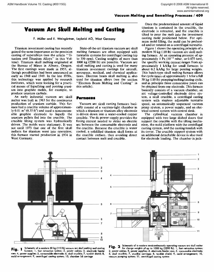
Vacuum arc skull casting furnaces basi- cally consist of a vacuum-tight chamber in which a titanium or titanium alloy electrode is driven down into a water-cooled copper crucible. The dc power supply provides the fusing current needed to strike an electric arc between the consumable electrode and the crucible. Because the crucible is water cooled, a solidified titanium skull forms at the crucible surface, thus avoiding direct contact between melt and crucible.
Once the predetermined amount of liquid titanium is contained in the crucible, the electrode is retracted, and the crucible is tilted to pour the melt into the investment casting mold positioned below. For opti- mum mold filling, the mold can be preheat- ed and/or rotated on a centrifugal turntable.
Figure 1 shows the operating principle of a modern 50 kg (110 lb) vacuum arc skull melt- ing furnace. At an operating pressure of ap- proximately 1 Pa (10 -2 mbar, or 0.075 torr), the specific working current ranges from ap- proximately 1 kA/kg for small furnaces to about 0.2 kA/kg for large pouring weights. This batch-type skull melting furnace allows for cycle times of approximately 1 h for a full 50 kg (110 lb) pumping/melting/casting cycle, and in principle three consecutive pours can be obtained from one electrode. This furnace basically consists of a vacuum chamber, an arc voltage-controlled electrode drive sys- tem, a skull crucible, a centrifugal casting system with stepless adjustable turntable speed, an automatically sequenced vacuum pump system, a power supply, and an elec- trical control system with control desk.
The cylindrical vacuum chamber is equipped with two large dished doors that support the crucible with the tilting mecha- nism, the mold platform with the centrifugal casting system, and the casting tundish with its cover. The crucible support system with an additional detachable device is also used for electrode loading. The chamber is jack-
Fig. ! Schematic of a modern 50 kg (110 Ib) vacuum arc skull melting and casting furnace. 1, fast retraction system; 2, power cables; 3, electrode feeder
ram; 4, power supplies; 5, consumable electrode; 6, skull crucible; 7, tundish shield; 8, mold arrangement; 9, centrifugal casting system; 10, chamber lid carriage
- 9
- 10
11
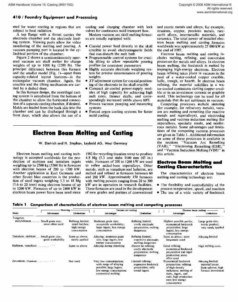
Fie. 2 Schematic of a modern semicontinuously operating vacuum arc skull melter for charge weights of up to 1000 kg (2200 Ib). 1, fast retraction system;
2, power cables; 3, power supplies; 4, electrode feeder ram; 5, consumable electrode; 6, skull crucible; 7, crucible carriage; 8, tundish shield; 9, mold arrangement; 10, vacuum pumping system; 11, centrifugal casting system
ASM Handbook Volume 15: Casting (#05115G)
Copyright © 2008 ASM International ® All rights reserved. www.asminternational.org
410 / Foundry Equipment and Processing
eted for water cooling in regions that are subject to heat radiation.
A top flange with a throat carries the electrode chamber and the electrode feed- ing system. Viewing ports allow for video monitoring of the melting and pouring. A vacuum pumping port is located in the cy- lindrical portion of the chamber.
Figure 2 shows a semicontinuously oper- ated vacuum arc skull melter for charge weights of up to 1000 kg (2200 lb). The principal difference between this furnace and the smaller model (Fig. l)---apart from capacity-related layout features--is the rectangular vacuum chamber. Again, the crucible and the tilting mechanism are car- ried by a dished door.
In this furnace design, the centrifugal cast- ing system is introduced from the bottom of the chamber to allow the horizontal connec- tion of a separate cooling chamber, if desired. Molds are loaded from the back side into the chamber and can be discharged through a front door, which also allows the use of a
cooling and charging chamber with lock valves for continuous mold transport flow.
Modern vacuum arc skull melting furnac- es are usually equipped with:
• Coaxial power feed directly to the skull crucible to avoid electromagnetic fields that can disturb the melt bath
• Programmable control systems for cruci- ble tilting to allow repeatable pouring profiles for consistent parameters
• Highly accurate electrode weighing sys- tem for precise determination of pouring weights
• XYadjustment system for coaxial position- ing of the electrode in the skull crucible
• Compact air-cooled power-supply mod- ules of high capacity for achieving high melt rates, thinner skulls, and corre- spondingly increased yields above 80%
• Proven vacuum pumping and measuring systems
• Forced argon cooling systems for faster mold cooling
Electron Beam Melting and Casting W. Dietrich and H. Stephan, Leybold AG, West Germany
Electron beam melting and casting tech- nology is accepted worldwide for the pro- duction of niobium and tantalum ingots weighing up to 2500 kg (5500 Ib) in furnaces with electron beams of 200 to 1500 kW. Another application in East Germany and other Soviet bloc countries is the produc- tion of steel ingots weighing 3.3 to 18 Mg (3.6 to 20 tons) using electron beams of up to 1200 kW. Furnaces of up to 2400 kW in electron beam power have been used since
1982 for recycling titanium scrap to produce 4.8 Mg (5.3 ton) slabs 1140 mm (45 in.) wide. Furnaces of 200 to 1200 kW are used to refine nickel-base superalloys. Other metals, such as vanadium and hafnium, are melted and refined in furnaces between 60 and 260 kW. Approximately 150 furnaces with melting powers ranging from 20 to 300 kW are in operation in research facilities. These furnaces are used in the development of new grades and purities of conventional
and exotic metals and alloys, for example, uranium, copper, precious metals, rare- earth alloys, intermetallic materials, and ceramics. The total power of installed elec- tron beam melting and casting furnaces worldwide was approximately 25 000 kW at the end of 1987.
Electron beam melting and casting in- cludes melting, refining, and conversion processes for metals and alloys. In electron beam melting, the feedstock is melted by impinging high-energy electrons. Electron beam refining takes place in vacuum in the pool of a water-cooled copper crucible, ladle, trough, or hearth. In electron beam refining, the material solidifies in a wa- ter-cooled continuous casting copper cruci- ble or in an investment ceramic or graphite mold. This technology can be used for all materials that do not sublimate in vacuum.
Competing processes include sintering (for example, for refractory metals), vacu- um arc melting and remelting (for reactive metals and superalloys), and electroslag melting and vacuum induction melting (for superaUoys, specialty steels, and nonfer- rous metals). Some advantages and limita- tions of the competing vacuum processes are given in Table 1. Additional information on some of these processes is available in the sections "Vacuum Arc Remelting (VAR)," "Electroslag Remelting (ESR)," and "Vacuum Induction Melting (VIM)" in this article.
Electron Beam Melting and Casting Characteristics
The characteristics of electron beam melting and casting technology are:
• The flexibility and controllability of the process temperature, speed, and reaction
• The use of a wide variety of feedstock
Table 1 Comparison of characteristics of electron beam melting and competing processes Siotering ] I Vacuum arc melting I [
Metal I Advantages Limitations Advantages Limitations Electron beam melting I
Advantages Limitations
Tungsten, molybdenum . . . . . . . Small grain size;
most often used
Tantalum, niobium.. . Small grain size; good workability
Hafnium, vanadium . . . . . . . . . . - •
Zirconium, titanium . . . . . . . . . • • •
Refining limited; small batches; high energy consumption
Same as above; rarely applied
Same as above
Not used
Moderate grain size; acceptable workability; large ingots; low energy consumption
Alloying; moderate grain size; large ingots; low energy consumption
Alloying during remelting
Very low contamination; wide range of alloying possible; large ingots; low energy consumption; economical melting
Refining limited; costly electrode preparation; melting dangerous
Refining limited; expensive electrode; melting dangerous
Almost no refining; costly electrode preparation; melting dangerous
Limited refining; expensive feedstock preparation; only round ingots
Highest possible purity; Large grain size; economical feedstock brittle product; preparation; large very rarely applied ingots; low energy consumption
Same as above; most Alloying limited frequently used
Good refining; economical feedstock preparation and ingot production; most often used
Economical feedstock preparation; refining of high-density inclusions; melting of slabs, ingots, and rods; high production rate; low energy consumption
High melting costs
Alloying limited; material losses from splatter; high furnace investment
ASM Handbook Volume 15: Casting (#05115G)
Copyright © 2008 ASM International ® All rights reserved. www.asminternational.org
Vacuum Mel t ing and Remelt ing Processes / 411
materials in terms of material quality, size, and shape
• The different methods of material pro- cessing available
• Product quality, size, and quantity
Contamination-free environment and crucible
Feedstock
Material e v a p o r a t i o n . - - , and splattering
Reflected \..~__.~, electron beam
X-ray emission
Flexible melting rate and refining dwell time
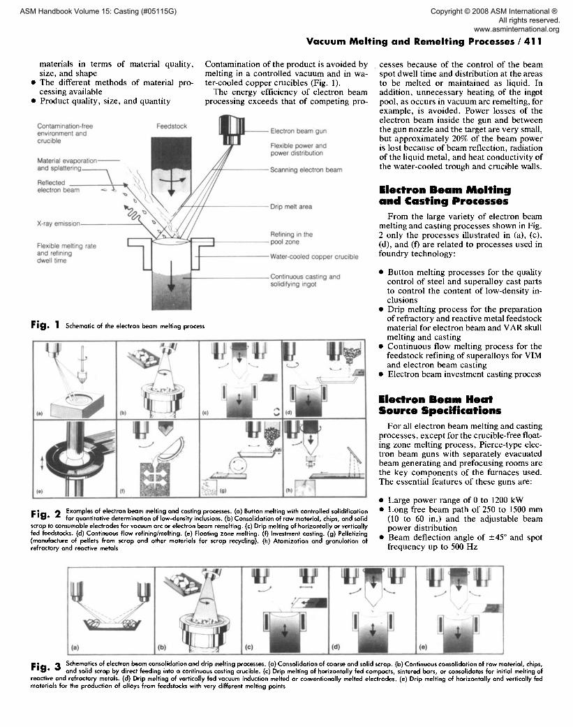
Contamination of the product is avoided by melting in a controlled vacuum and in wa- ter-cooled copper crucibles (Fig. 1).
The energy efficiency of electron beam processing exceeds that of competing pro-
Electron beam gun
Flexible power and power distribution
Scanning electron beam
Drip melt area
Refining in the pool zone
Water-cooled copper crucible
Continuous casting and solidifying ingot
Fig. 1 Schematic of the electron beam melting process
(a)
li' i i ( , ' ) ~ (g) (h) ~ ! (f)
F i g . 2 Examples of electron beam melting and casting processes. (a) Button melting with controlled solidification for quantitative determination of low-density inclusions. (b) Consolidation of raw material, chips, and solid
scrap to consumable electrodes for vacuum arc or electron beam remelting. (c) Drip melting of horizontally or vertically fed feedstocks. (d) Continuous flow refining/melting. (e) Floating zone melting. (f) Investment casting. (g) Pelletizing (manufacture of pellets from scrap and other materials for scrap recycling). (h) Atomization and granulation of refractory and reactive metals
cesses because of the control of the beam spot dwell t ime and distribution at the areas to be melted or maintained as liquid. In addition, unnecessary heating of the ingot pool, as occurs in vacuum arc remelting, for example, is avoided. Power losses of the electron beam inside the gun and between the gun nozzle and the target are very small, but approximately 20% of the beam power is lost because of beam reflection, radiation of the liquid metal, and heat conductivity of the water-cooled trough and crucible walls.
Electron Beam Mel t ing and Casting Processes
From the large variety of electron beam melting and casting processes shown in Fig. 2 only the processes illustrated in (a), (c), (d), and (f) are related to processes used in foundry technology:
• Button melting processes for the quality control of steel and superalloy cast parts to control the content of low-density in- clusions
• Drip melting process for the preparation of refractory and reactive metal feedstock material for electron beam and VAR skull melting and casting
• Continuous flow melting process for the feedstock refining of superalloys for VIM and electron beam casting
• Electron beam investment casting process
Electron Beam Heat Source Specifmcat,ons
For all electron beam melting and casting processes, except for the crucible-free float- ing zone melting process, Pierce-type elec- tron beam guns with separately evacuated beam generating and prefocusing rooms are the key components of the furnaces used. The essential features of these guns are:
• Large power range of 0 to 1200 kW • Long free beam path of 250 to 1500 mm
(10 to 60 in.) and the adjustable beam power distribution
• Beam deflection angle of ---45 ° and spot frequency up to 500 Hz
(e) (b) /~ Schematics of electron beam consolidation and drip melting processes. (a) Consolidation of coarse and solid scrap. (b) Continuous consolidation of raw material, chips,
F i g . 3 and solid scrap by direct feeding into a continuous casting crucible. (c) Drip melting of horizontally fed compacts, sintered bars, or consolidates for initial melting of reactive and refractory metals. (d) Drip melting of vertically fed vacuum induction melted or conventionally melted electrodes. (e) Drip melting of horizontally and vertically fed materials for the production of alloys from feedstocks with very different melting points
ASM Handbook Volume 15: Casting (#05115G)
Copyright © 2008 ASM International ® All rights reserved. www.asminternational.org

412 / Foundry Equipment and Processing
Table 2 Melting and refining data of refractory and reactive metals and alloy steels gained in laboratory and pilot production furnaces
Electron beam Total specific Interstitial elements Ingot Ingot Integral power o f Operating vacuum melting in feedstock
Feedstock size, diameter, weight, melting rate, second melt, pressure of last melt, energy, Material and final ingot, ppm Hardness, Metal mm (in.) mm (in.) kg (Ih) kg/h (Ib/h) kW Pa (tort) kW • h/kg yield, % C O N H HB
Tungsten . . . . . . . . . . 40 (1.6) diam
55 (2.2) diam, 100 (4) long
Tantalum . . . . . . . . . 60 (2.4) diam
60 (2.4) square, 160 (6.3) long
Molybdenum . . . . . . 100 (4) diam 100 (4) diam 120 (4.7) square, 180 (7.1) long
Niobium . . . . . . . . . 80 (3.2) square, 150 (6) long 120 (4.7) square, 180 (7. I) long
Hafnium . . . . . . . . . 60 (2.4) square 80 (3.2) diam 100 (4) diam 100 (4) diam
Zirconium . . . . . . . 60 (2.4) square, 100 (4) long 60 (2.4) square, 150 (6) long
Vanadium . . . . . . . 60 (2.4) diam, 80 (3.2) long
Titanium . . . . . . . . 100 (4) diam Ti-6AI-4V . . . . . . . • • • Ti-8Al-lMo-IV . . . . 100 (4) diam
4340 steel . . . . . . . . . 80 (3.2) diam
60 (2.4)
115 ( 4 . 5 )
80 (3.2)
160 (6.3)
100 (4)
180 (7.1)
150 (6)
180 (7.1)
80 (3.2)
130 (5.1) 173 (380)
100 (4) 19.5 (43)
150 (6) 179 (395)
80 (3.2) 7.7 (17)
100 (4) 28.2 (62)
100 (4) 28.2 (62)
150 (6) 31 (70) 150 (6) 31 (70)
37 (80) 10.5 (23)
200 (440) 20 (44)
65 (145) 16.7 (37)
523 (1150) 38.4 (85)
64 (140) 12.5 (27.5)
408 (900) 50.2 (111)
227 (500) 17.6 (39)
326 (720) 13.2 (29)
40 (90) 1.7 (3.7)
7.5 (16.5)
14.3 (31.5)
73 (161)
2.8 (6.2)
45.2 (100)
22.5 (50)
10 (22) 80 (176)
(a) The reproducibility of the refining data could not be confirmed.
119
3O0
130
371
130
290
240
218
80
110
80
250
80
87
6O
52 80
8 x 10 -3 (6x 10 -s)
2 x 10 -2 (1.5 × 10 -4 )
8 X 10 -3 (6 × 10 -5)
3 × 10 -3 (2 × 10 -s)
8 × 10 -4 (6 X 10 -6)
10 -3 (7.5 x 10 -6)
10 -2 (7.5 x 10 -5)
5 x 10 -3 (3.8 X 10 -s)
5 x 10 -3 (3.8 X 10 -s)
4 X 10 -3 (3 x 10 -s)
8 x 10 -3 (6 x 10 -5 )
2 x 10 -2 (1.5 x 10 -4 )
8 x 10 -3 (6 x 10 -5 )
0.8 (6 x 10 -3)
0.4 (3 x 10 -3 )
4 x 10 -3 (3 × 10 -5 ) 2.0 (0.015)
10.3
9.9
6.0
8.30
10.4
5.2
12.3
15.9
38
14.7
4.6
2.6
3.1
1.91
2.66
1.67 1.0
• . . 70 4100 30 10 93.1 10 8 5 1 • . . 200 5000 50 20 90 10 8 7 1 • . . 100 1200 140 10 92 10 75 30 1 . . . . . . 650 13 10 91.8 6 15 13 2 - • • 170 810 50 10 95 12 10 10 2 • • • 200 750 60 10 96.8 10 12 11 2 . . . 160 5220 554 35 87 12 106 60 5
• . . 80 4500 330 40 96.8 6 111 52 8 . . . . . . 1870 95 2 93.1 • • • 170 25 I • • • 500 900 100 2 93.5 100 200 50 1 . . . . . . 950 95 30 88.2 • • • 545 30 3 . . . . . . 950 95 30 . . . . . . 735 48 9 . . . . . . 1045(a) 210(a) 16(a) 91 . . . 235(a) 95(a) 13(a) . . . . . . 2180 100 30 99 • • - 1850 80 16 . . . . . . 890 70 ' • • 98 • • • 730 50 • • • • • • 3900 63 100 0.3 93 4300 2.4 26 0.08 99 3622 10 78 0.10
200
210
65
69
140
140
77
66
160
170
120
125
30-100
• U s a b l e v a c u u m p r e s s u r e r a n g e b e t w e e n I a n d 0.0001 P a (10 -2 a n d 10 - 6 m b a r , o r 7.5 × 10 -3 a n d 7.5 x 10 -7 to r r )
• Re l i ab i l i ty o f t h e gun a n d c a t h o d e s y s t e m
T h e p o w e r c on t r o l and d i s t r ibu t ion s y s t e m a l lows a ve ry a c c u r a t e d i s t r ibu t ion o f b e a m p o w e r and e n e r g y fo r ach iev ing the r equ i red hea t ing fo r mate r ia l mel t ing , supe rhea t ing , ref ining, and e l e c t r o t h e r m a l e f fec t s .
Button Melting for Quality Control
T h e bu t ton me l t ing p r o c e s s (Fig. 2a) s e r v e s to con t ro l the qua l i ty o f f e e d s t o c k m a t e r i a l s fo r i n v e s t m e n t ca s t ing and to p r o d u c e cas t ing samples • In c o n t r a s t to t he c o n v e n t i o n a l e lec- t ron b e a m mel t ing p r o c e s s , th is p r o c e s s is no t u sed for ref in ing, bu t on ly fo r f lo ta t ion and c o n c e n t r a t i o n o f l o w - d e n s i t y inc lus ions• Dur- ing the e igh t - s t ep p r o c e s s , the s a m p l e is hea t - ed and dr ip me l t ed . L o w - d e n s i t y inc lus ions a re f loa ted to t he su r f ace and c o n c e n t r a t e d in t he c e n t e r o f t he poo l o f m o l t e n me ta l dur ing con t ro l l ed so l id i f ica t ion by c o m p u t e r - c o n - t ro l led r e d u c t i o n o f b e a m p o w e r a n d c i rcular e l e c t r o t h e r m a l s t i rr ing. T h e c o n c e n t r a t e d im- pur i t ies can be ident i f ied a n d eva lua t ed by c o n v e n t i o n a l me ta l l og raph i c m e t h o d s , bu t t he s ize o f t he raft g ives the f i rs t ind ica t ion o f the quan t i t y o f impur i t i e s in t h e meta l .
M o s t b u t t o n me l t i ng f u r n a c e s a re c o m - p l e t e ly a u t o m a t e d a n d m i c r o p r o c e s s o r c o n - t ro l l ed to g u a r a n t e e p r o c e s s r ep roduc ib i l i t y • M e l t i n g is usua l ly c a r r i ed ou t in t he p r e s - su re r ange o f l to 0.001 Pa (10 -2 to l0 -5 m b a r , o r 7.6 × 10 -3 to 7.6 × 10 - 6 tor r ) .
Drip Melting T h e dr ip me l t i ng p r o c e s s e s (Fig. 3c a n d d)
a re p r imar i ly u s e d fo r t he p r o d u c t i o n o f c l e an , m o s t l y duc t i l e i ngo t s o f r e f r a c t o r y and r e a c t i v e m e t a l s o r o f spec i a l t y s tee l s • T h e f e e d s t o c k fo r t h e f i r s t me l t (Fig. 3c) c a n be c o m p a c t e d s p o n g e , g ranu la r , p o w d e r , o r s c r a p , w h i c h migh t be p r e s i n t e r e d in a vac - u u m hea t i ng fu rnace • In s o m e c a s e s , l o o s e r aw ma te r i a l s can be c o n s o l i d a t e d in a wa- t e r - c o o l e d c o p p e r t r ough (Fig. 3a). T h e c o n - s o l i d a t e d ingot c a n t h e n be fed h o r i z o n t a l l y fo r d r ip mel t ing• R a w mate r i a l tha t is c o n - t i n u o u s l y c o n s o l i d a t e d in a w a t e r - c o o l e d c o p p e r c ruc ib l e w i th a r e t r a c t a b l e b o t t o m p la t e (Fig. 3b) c a n be f e d h o r i z o n t a l l y o r ve r t i ca l ly fo r d r ip me l t i ng . In b o t h c o n s o l i - d a t i o n p r o c e s s e s , on ly 20 to 80% o f t h e ma t e r i a l is me l t ed• R e f i n i ng a n d l o s s e s o f ma t e r i a l by sp l a t t e r i ng a re negl igible•
D r i p me l t ing o f h o r i z o n t a l l y f ed c o m p a c t s is t h e m o s t f r e q u e n t l y u s e d p r o c e s s fo r t h e p r o d u c t i o n o f i ngo t s f r o m r e f r a c t o r y o r re- a c t i v e meta l s • T h e r e su l t i ng ingot is o f suf-
f i c i en t pu r i t y , b u t h a s an a r e a o f i n h o m o g e - ne i ty c a u s e d b y t h e s h a d o w o f t h e h o r i z o n t a l l y f e d bar . T w o o r m o r e e l e c t r o n g u n s a r e u s e d in d r i p m e l t i n g to m a k e u s e o f r e f l e c t e d e l e c t r o n b e a m s a n d to r e d u c e e v a p o r a t i o n a n d sp la t t e r ing• T h e e n d o f a c o m p a c t is w e l d e d to t h e f r o n t o f t he fol- l owi ng o n e to a v o i d d r o p p i n g s emi so l i d ma- ter ia l in to t h e p o o l . T a b l e 2 l is ts p r o c e s s i n g p a r a m e t e r s t ha t h a v e b e e n s u c c e s s f u l l y u s e d to e l e c t r o n b e a m m e l t v a r i o u s r e a c t i v e and r e f r a c t o r y m e t a l s a n d 4340 a l loy s tee l .
Vertical Feeding of Ingots. R e f r a c t o r y a n d r e a c t i v e m e t a l i ngo t s o f h igh pur i ty , h o m o g e n e i t y , a n d s m o o t h s u r f a c e a r e re- m e l t e d b y ve r t i ca l f e e d i n g (Fig. 3d). T h e m o l t e n m e t a l d r o p l e t s run d o w n the con ica l , r o t a t i ng e l e c t r o d e t ip , a r e r e f i n e d , a n d t h e n d r o p in to t h e p o o l c en t e r • T h e c ruc ib l e poo l is n o r m a l l y o f t h e s a m e d i a m e t e r as t he e l e c t r o d e b u t is s o m e t i m e s sma l l e r o r larg- er . I t is k e p t in t h e l iquid s t a t e to a l low final r e f in ing a n d to g u a r a n t e e i ngo t h o m o g e n e - i ty. B e c a u s e t w o o r m o r e e l e c t r o n g u n s a re u s e d , t h e e n t i r e p o o l c a n b e equa l ly b o m - b a r d e d ; t h u s , s h a d o w e f f e c t s o f t h e e lec- t r o d e c a n b e e l im ina t ed •
S i m u l t a n e o u s m e l t i n g o f h o r i z o n t a l l y and ve r t i ca l ly f e d e l e c t r o d e s (Fig. 3e) can be u s e d fo r t h e p r o d u c t i o n o f c r i t i ca l a l loys . In th is c a s e , t h e f e e d s t o c k s h o u l d be o f t he d e s i r e d pur i ty •
ASM Handbook Volume 15: Casting (#05115G)
Copyright © 2008 ASM International ® All rights reserved. www.asminternational.org

V a c u u m M e l t i n g a n d R e m e l t i n g P r o c e s s e s / 4 1 3
and interlocking systems prevent operation failures and accidents.
The control system allows the adjustment and control of such operating process pa- rameters as electron beam power, operating vacuum level, material feed rate, and ingot withdraw speed. The control system also records and logs the process data.
Power Supply Units. One or more high- voltage power supply units are needed to supply the electron beam guns with the required continuous voltage (30 to 40 kV). The beam power of each gun can be adjust- ed between zero and maximum power with an accuracy of -+2%.
Other Equipment. Large production fur- naces are equipped with lock-valve systems to allow simultaneous melting and unload- ing of ingots without breaking the vacuum in the melt chamber. Production is thus limited only when the condensate remaining in the melt chamber requires cleaning or when a different alloy is to be melted.
Drip melting of 330 mm (13 in.) square steel billet in a 1100 kW single-gun furnace. Melt rate: 1000 kg/ F i g . 4 h (2200 Ib/h). Courtesy of VEB-I:delstahlwerk, East Germany
Horizontally Fed Ingots. Drip melting of horizontally fed material with a single elec- tron gun (Fig. 4) is used for refining some steel alloys in East Germany and other Soviet bloc countries. In this process, the feedstock size is smaller than the pool di- ameter to minimize the shadow effect of the horizontally fed bar. In production units, feeding can be carried out from two oppo- site sides.
Other Process Considerations. To en- sure the production of clean, homogeneous metals and alloys in electron beam drip melting furnaces, various aspects of mate- rial processing and handling must be con- trolled. Key considerations include:
• Dimensions and quality of the feedstock, and the feeding system used
• Ingot cooling and unloading during melt- ing of another ingot
• Passivation and removal of condensates from the melt chamber
• Planning of melt sequences to minimize the number of furnace cleanings required
• Routine preventive furnace maintenance to ensure reliability
• Operator skill in operation of the furnace • Material yield and energy consumption
Equipment for Drip Melt ing The essential equipment groups required
for drip melting--melting furnaces, control systems, and power supply units---are all im- portant for achieving optimum productivity.
The melting furnace (Fig. 5) includes the electron beam gun as the heat source, ma- terial feeding and ingot withdrawal systems, a crucible for material solidification, and a vacuum system to maintain the low pres- sure. Process observation, both visually and with video systems, is possible through viewports. The melt chamber flanges are equipped with x-ray absorbing steel boards,
Characteristics of Electron Beam Drip Mel ted Metals
Electron beam melted and refined material is of the highest quality. The amount of inter- stitials present is very low, and trace elements of specific high vapor pressure can also be reduced to very low values (Ref 1, 2).
R e a c t i v e a n d R e f r a c t o r y M e t a l s Tantalum and niobium ingots have
smooth surfaces and are of sufficient ductil- ity that they can be cold worked, and sheets and wires can be produced.
Tungsten and molybdenum ingots are also of the highest possible purity, but the ingots are brittle because of the very large grain size and the concentration of impuri- ties at grain boundaries.
Hafnium. Electron beam melted hafnium is of higher ductility than the vacuum arc remelted metal (Ref 3). The main application of electron beam melted hafnium is as control elements for submarine nuclear reactors.
Vanadium is refined by electron beam drip melting. The aluminothermically pro- duced feedstock is drip melted in several steps. During this procedure, the ingot diam- eter is reduced at each step by approximately 30 to 40 mm (1.2 to 1.6 in.) to obtain an ingot 30 to 40 mm (1.2 to 1.6 in.) in diameter, regardless of the initial ingot diameter. The clean vanadium ingots are primarily used in nuclear reactor applications (Ref 4).
Applications for electron beam melted refractory and reactive metals are listed in Table 3.
S t e e l s The purity and properties of electron beam
melted steels are in some respects better than those of vacuum arc and electroslag remelted steels, but the processing costs are higher. The electron beam melting of steel is primar-
ASM Handbook Volume 15: Casting (#05115G)
Copyright © 2008 ASM International ® All rights reserved. www.asminternational.org

414 / Foundry Equipment and Processing
Melting chamber
Feeding systems
Oil diffusion pump Water-cooled copper crucible
Device for ingot withdrawal
U I
/
M
Electron beam Deflected electron beam
Charging valves Remelting rod
Ingot
Single-gun 1200 kW furnace for horizontal drip melting of steels. Melting rates of up to 1100 kg/h (2425 Fig. 5 Ib/hl are possible.
Table 3 Principal appl icat ions for vacuum arc remelted (VAR), electron beam melted (EB), and powder meta l lu rgy (P/M) reactive and refractory meta l ingots Metal Applications
Reactive metals, VAR and EB melting
Hafnium . . . . . . . . . . . . . . . . . . . . . . . . . . . . . . . . . .
Vanadium . . . . . . . . . . . . . . . . . . . . . . . . . . . . . . . . .
Zirconium . . . . . . . . . . . . . . . . . . . . . . . . . . . . . . . . .
Titanium . . . . . . . . . . . . . . . . . . . . . . . . . . . . . . . . . .
Refractory metals, EB melting and P/M
Tungsten . . . . . . . . . . . . . . . . . . . . . . . . . . . . . . . . . .
Tantalum . . . . . . . . . . . . . . . . . . . . . . . . . . . . . . . . .
Molybdenum . . . . . . . . . . . . . . . . . . . . . . . . . . . . . .
Niobium . . . . . . . . . . . . . . . . . . . . . . . . . . . . . . . . . .
Flash bulbs and glow discharge tubes for the electronics industry; control rods and breakoff elements in submarine nuclear reactors
Targets for high deposition rate sputtering processes in the electronics industry; breakoff elements, fixtures, and fasteners in nuclear reactors; standards for basic research; alloying element for certain high-purity alloys
Getter material in tubes in the electronics industry; stripes for flash bulbs; fuel claddings, fasteners, and fixtures for nuclear reactors
Components for bleaching equipment and desalination plants in the chemical industry; superconductive wires; turbine engine disks, blades and housings, rain erosion boards, landing legs, wing frames, missile cladding, and fuel containers in the aircraft and aerospace industries; shape memory alloys; biomedical fixtures and implants; corrosion resistant claddings
Heating elements, punches and dies, and nonconsummable electrodes for arc melting and gas tungsten arc welding for metal processing equipment; targets for x-ray equipment and high sputtering rate devices such as very large-scale integrated circuits, cathodes and anodes for electronic vacuum tubes in the electronics industry; radiation shields in the nuclear industry; cladding and fasteners for missile and reentry vehicles
Condensers, autoclaves, heat exchangers, armatures, and fittings for the chemical industry; electrolytic capacitors for the electronics industry; surgical implants; fasteners for aerospace applications
Dies for conventional and isothermal forging equipment; electrodes for glass melting; targets for x-ray equipment; cladding and fasteners for missile and reentry vehicles
Superconductive wire for energy transmission and large magnets for the electrical and electronics industries; heavy ion accelerators and radio frequency cavities for nuclear applications; components for aircraft and aerospace applications
ily used in Eas t Germany and other Soviet bloc countries. The resulting ingots are up to 1000 mm (40 in.) in diameter and weigh up to 18 Mg (20 tons). The furnaces used have been in operation since 1965, and have beam pow- ers of up to 1200 kW. Larger furnaces for the production of ingots weighing up to 30 to 100 Mg (33 to 110 tons) are under construction (Ref 5).
The essential advantage of the electron beam melting o f steel is the drastic reduction of metallic and nonmetallic impurities and interstitial e lements (Ref 6, 7). The principal applications for electron beam melted steels are in the machinery industry for parts for which high wear resistance and long service life are required. The extended service lives of the parts and the reduced manufacturing time (for example, less surface polishing is required for electron beam melted steel) can justify the higher material costs.
The e lec t ron beam melt ing of steel and superal loys can become much more eco- nomical when melt ing and refining are done by cont inuous f low melt ing or cold hearth refining. These melt ing and refining meth- ods reduce energy costs and minimize ma- terial losses.
Continuous Flow Mol t ing The continuous flow melting process (cold
hearth refining process) (Fig. 6) was devel- oped approximately 10 years after drip melt- ing (Ref 8). Continuous flow melting is mainly used for refining specialty steels and superal- loys and for refining and recycling reactive metal scrap, especially Ti-6AI-4V from high- density tungsten carbide tool tips (Ref 9).
Pr inc ip les of C o n t i n u o u s F low M e l t i n g
Cont inuous f low melt ing (Fig. 7) is the most f lexible vacuum metallurgical melting process . It is a two-s tage process in which the first step (material feeding, melting, and refining) takes place in a water -cooled cop- per trough, ladle, or hearth. In the second step, solidification occurs in one of several round, rectangular , or special ly shaped wa- ter-cooled cont inuous copper crucibles. Both process steps are nearly independent f rom each other ; they are l inked only by the cont inuous f low of the liquid metal stream. The major refining act ions are carried out in the hearth, but some postref ining takes place in the pool of the cont inuous casting crucible, similar to the drip melt ing of hor- izontal ly fed billets. Ref inement in continu- ous f low melt ing occurs by vacuum distilla- t ion in the hear th pool , superheat ing, and stirring of the mol ten metal pool.
Removal of Impurities. Most impurities with densities lower than that of the melt (for example, metalloids in steels and superalloys) can be segregated by flotation and formed into a slag raft. The raft is then held in place by either mechanical or electrothermal
ASM Handbook Volume 15: Casting (#05115G)
Copyright © 2008 ASM International ® All rights reserved. www.asminternational.org

Vacuum Melting and Remelting Processes / 415
Programmed electron beams for refining low-density inclusions and maintaining a flat. shallow inaot oool
3n beam feedstock lat
9ntal bar feeding
Beam rot on the pc
per anical val of ~ions
Fig. 6 Schematic of the continuous flow melting process
means. Impurities denser than the melt, such as tungsten carbide tool tips in titanium, are removed by sedimentation. Inclusions with densities such that efficient flotation or sedi- mentation does not occur can be partially removed by adhesion to the slag raft.
Hearth dimensions are based on the type and amount of refining required. For exam- ple, hearths for vacuum distillation should be nearly square and relatively deep to allow sufficient melt stirring. For flotation refining, the hearth should be long and narrow (for superalloys, approximately 10 mm, or 0.4 in., of hearth length for each 100
kg/h, or 220 lb/h, of melt rate is recommend- ed). Hearths for titanium alloy scrap recy- cling can be relatively short if all the mate- rials can be transported to the pool of the hearth rather than to the ingot pool.
Feeding. Material feeding criteria include 100% homogenous material transportation to avoid uncontrolled evaporation of alloy- ing elements and correct feeding into or above the hearth pool. Horizontal feeding of compacted, premelted, or cast material is most often used. Loose scrap and raw mate- rial are used only when compaction is too expensive. Feeding of liquid metal was used
Table 4 Comparison of the characteristics of drip melting and continuous flow melting Characteristic Refractory metals Reactive metals, superalloys, and specialty steels
Power density . . . . . . . . . . . . . . . . . . . . . . . . . . . . . High Soft; smoothly distributed Inclusions . . . . . . . . . . . . . . . . . . . . . . . . . . . . . Irrelevant Must be removed Ingot shape and structure . . . . . . . . . . . . . . . Round; coarse grain Round or flat; fine grain, segregation-free Mass production . . . . . . . . . . . . . . . . . . . . . . . Low High Competitive economical processes . . . . . . . Vacuum arc remelting Vacuum arc remelting; electroslag remelting Preferred method . . . . . . . . . . . . . . . . . . . . . . Drip melting Continuous flow melting
in one of the first continuous flow melting furnaces to produce a ferritic steel in a vacu- um induction furnace (Ref 10). Postrefining was carried out in a cascade of five hearths 1.5 m (60 in.) long and 1 m (40 in.) wide.
Casting and Solidification. The criteria for material casting and solidification include the shape of the final product and the solidi- fication rate required to avoid ingot tears or other defects and to ensure a homogeneous ingot structure. The multiple casting of small ingots is sometimes used, especially when forging is impossible because of the brittle- ness of the solidified material (for example MCrAly wear-resistant coating alloys). The casting of round and rectangular ingots and slabs is common practice, and the continuous casting of hollow ingots is also being used (Ref I 1). The casting of segregation-free in- gots and ingots with a fine grain size is under development to improve the workability of superalloys (Ref 12, 13).
Continuous Flow Versus Drip Melting
Table 4 compares the essential features of drip melting and continuous flow melting. Generally, continuous flow melting is used for all refractory metals, superalloys, and specialty steels, especially when flotation or sedimentation of inclusions is required. Drip melting is used for refractory metals because of their high melting points and the resulting high heat losses to the water- cooled copper crucible. Depending on pro- duction quantity, double or triple drip melt- ing may require less energy than a single continuous flow melt of some materials, such as niobium.
Refining and Production Data Data on continuous flow electron beam
melting and refining in laboratory and pilot production furnaces are given in Table 5. The data demonstrate the effectiveness of the pro- cess in reducing impurities and interstitial elements. It can also be seen that the selective evaporation of chromium from superalloys can be controlled by the distribution of beam power at the trough pool and by controlling trough pool area and melt rate. The selective evaporation of aluminum from Ti-6A1-4V al- loy is much more difficult to control; addition- al aluminum must be used to compensate for the aluminum evaporated.
Equipment for Continuous Flow Electron Beam Melting
The equipment required for continuous flow melting is different from that used in drip melting mainly because of the trough and the somewhat larger melting chamber. In addition, because of the materials often melted in the continuous flow process (su- peralloys and titanium alloys), additional instrumentation is often provided. This may include an ingot pool level control system,
ASM Handbook Volume 15: Casting (#05115G)
Copyright © 2008 ASM International ® All rights reserved. www.asminternational.org
416 / Foundry Equipment and Processing
/
/ - / / ~ / / .........
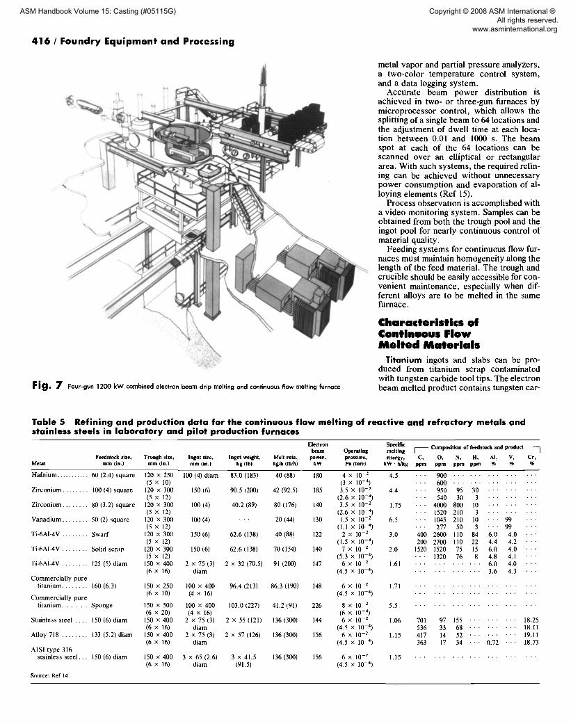
Fig. 7 Four-gun 1200 kW combined electron beam drip melting and continuous flow melting furnace
metal vapor and partial pressure analyzers, a two-color temperature control system, and a data logging system.
Accurate beam power distribution is achieved in two- or three-gun furnaces by microprocessor control, which allows the splitting of a single beam to 64 locations and the adjustment of dwell time at each loca- tion between 0.01 and 1000 s. The beam spot at each of the 64 locations can be scanned over an elliptical or rectangular area. With such systems, the required refin- ing can be achieved without unnecessary power consumption and evaporation of al- loying elements (Ref 15).
Process observation is accomplished with a video monitoring system. Samples can be obtained from both the trough pool and the ingot pool for nearly continuous control of material quality.
Feeding systems for continuous flow fur- naces must maintain homogeneity along the length of the feed material. The trough and crucible should be easily accessible for con- venient maintenance, especially when dif- ferent alloys are to be melted in the same furnace.
Characteristics of Continuous Flow Mel ted Mater ia ls
Titanium ingots and slabs can be pro- duced from titanium scrap contaminated with tungsten carbide tool tips. The electron beam melted product contains tungsten car-
Table 5 Refining and production data for the continuous flow melting of reactive and refractory metals and stainless steels in laboratory and pilot production furnaces
Electron Specific beam Operating melting ] Composition o f feedstock and product [
Feedstock size, Trough size, Ingot size, Ingot weight, Melt rate, power, pressure, energy, C, O, N, H , AI, V, Cr, Metal mm (in.) mm (in.) mm (in.) kg 0b) kg/h 0h/h) k W Pa (tort) k W • h/kg ppm ppm ppm ppm % % %
9 0 0 . . . . . . . . . . . . . . . 6 0 0 . . . . . . . . . . . . . . .
H a f n i u m . . . . . . . . . . . 60 (2.4) square 120 × 250 100 (4) d i am (5 x 10)
Z i r con ium . . . . . . . . I00 (4) square 120 x 300 150 (6) (5 x 12)
Z i r c o n i u m . . . . . . . . 80 (3.2) squa re 120 x 300 100 (4) (5 x 12)
V a n a d i u m . . . . . . . . 50 (2) square 120 x 300 100 (4) (5 x 12)
Ti-6AI-4V . . . . . . . . S w a r f 120 x 300 150 (6) (5 x 12)
Ti-6AI-4V . . . . . . . . Solid sc rap 120 x 300 150 (6) (5 × 12)
Ti-6AI-4V . . . . . . . . 125 (5) d i am 150 × 400 2 x 75 (3) (6 × 16) d i am
Co mmerc i a l l y pure t i t an ium . . . . . . . . 160 (6.3) 150 x 250 100 x 400
(6 x 10) (4 x 16) C o m m e r c i a l l y pure
t i t an ium . . . . . . Sponge 150 x 500 100 x 400 (6 x 20) (4 x 16)
Sta inless steel . . . . 150 (6) d i am 150 x 400 2 x 75 (3) (6 x 16) d i a m
Alloy 718 . . . . . . . . 133 (5.2) d i am 150 x 400 2 x 75 (3) (6 x 16) d i a m
A I S I type 316 s ta inless s t e e l . . . 150 (6) d i a m 150 x 400 3 x 65 (2.6)
(6 x 16) d i a m
Source: Ref 14
83.0 (183) 40 (88)
90.5 (200) 42 (92.5)
40.2 (89) 80 (176)
. - - 20 (44)
62.6 (138) 40 (88)
62.6 (138) 70 (154)
2 x 32 (70.5) 91 (200)
96.4 (213) 86.3 (190)
103.0 (227) 41.2 (91)
2 × 55 (121) 136 (300)
2 × 57 (126) 136 (300)
3 x 41.5 136 (300) (91.5)
180 4 x 10 -2 (3 x 10 -4)
185 3.5 X 10 - 2 (2.6 x 10 -4)
140 3.5 X 10 - 2 (2.6 x l0 -4)
130 1.5 x l0 2 (1.1 x l0 4)
122 2 X 10 - 2 (1.5 x 10 - 4 )
140 7 × 10 2 (5.3 x 10 4)
147 6 X l0 2 (4.5 x 10 - 4 )
148 6 × 10 - 2 (4.5 × 10 - 4 )
226 8 x 10 -2 (6 x 10 -4)
144 6 x 10 -2 (4.5 x 10 4)
156 6 × 10 - z (4.5 x 10 - 4 )
156 6 X 10 - 2 (4.5 x 10 - 4 )
4.5
4.4
1 .75
6.5
3.0
2.0
950 95 30 . . . . . . . . . 540 30 3 . . . . . . . . .
4000 800 10 . . . . . . . . . 1520 210 3 . . . . . . . . . 1045 210 10 . . . 99 ' - " 277 50 3 . . . 99 . ' '
400 2600 110 84 6.0 4.0 ' ' 200 2700 110 22 4.4 4.2 ' "
1520 1520 75 15 6.0 4.0 ' ' • . . 1320 76 8 4.8 4.1 • '
1.61 . . . . . . . . . . . . 6.0 4.0 • • . . . . . . . . . . . . 3.6 4.3 • •
1.71 . . . . . . . . . . . . . . . . . . . . .
5.5 . . . . . . . . . . . . . . . . . . . . .
1.06 701 97 155 . . . . . . . . . 18.25 536 33 68 . . . . . . . . . 18.11
1.15 417 14 52 . . . . . . . . . 19.11 363 17 34 . ' ' 0.72 ' ' ' 18.73
1.15 . . . . . . . . . . . . . . . . . . . . .
ASM Handbook Volume 15: Casting (#05115G)
Copyright © 2008 ASM International ® All rights reserved. www.asminternational.org


![Melt Superheating on the Microstructure and Mechanical ... · Si alloys, by using superheating treatment, the primary sili-con grains were remarkably refined [17,18]. The reported](https://static.fdocuments.net/doc/165x107/5ed28a85af2f306b9a013ece/melt-superheating-on-the-microstructure-and-mechanical-si-alloys-by-using-superheating.jpg)