PY2N20 Material Properties and Phase Diagrams€¦ · PY2N20 Material Properties and Phase Diagrams...
28
PY2N20-8 PY2N20 Material Properties and Phase Diagrams Lecture 8 P. Stamenov, PhD School of Physics, TCD
Transcript of PY2N20 Material Properties and Phase Diagrams€¦ · PY2N20 Material Properties and Phase Diagrams...

PY2N20-8
PY2N20
Material Properties and
Phase Diagrams
Lecture 8
P. Stamenov, PhD
School of Physics, TCD

Phase transformations
Fe
3C
(ce
me
ntite
)
1600
1400
1200
1000
800
600
400 0 1 2 3 4 5 6 6.7
L
g
(austenite)
g +L
g + Fe3C
a + Fe3C
L+Fe3C
d
Co , wt% C
1148°C
T(°C)
727°C

Eutectic, Eutectoid and Peritectic
Reactions
Eutectic Reaction
Eutectoid reaction
)2()1( phaseSolidphaseSolidLiquid
)3()2()1( phaseSolidphaseSolidphaseSolid
Peritectic Reaction
)3()2()1( phaseSolidphaseSolidphaseLiquid

Phase Transformations
Nucleation nuclei act as seed points to grow crystals
for nucleus to form
rate of addition of atoms > rate of loss
once nucleated, growth equilibrium
Driving force to nucleate increases as we increase T supercooling (eutectic, eutectoid)
superheating (peritectic)
Small supercooling few nuclei - large crystals
Large supercooling rapid nucleation - many nuclei,
small crystals

Solidification: Nucleation
Processes
Homogeneous nucleation
nuclei form in the bulk of liquid metal
requires supercooling (typically 80-300 °C max)
Heterogeneous nucleation much easier since stable “nucleus” is already present
Could be wall of mold or impurities in the liquid phase
Think of why you’d been asked never to put a used spoon back into a honey jar…
allows solidification with only 0.1-10 ºC supercooling
concentration drive is also possible and often used!
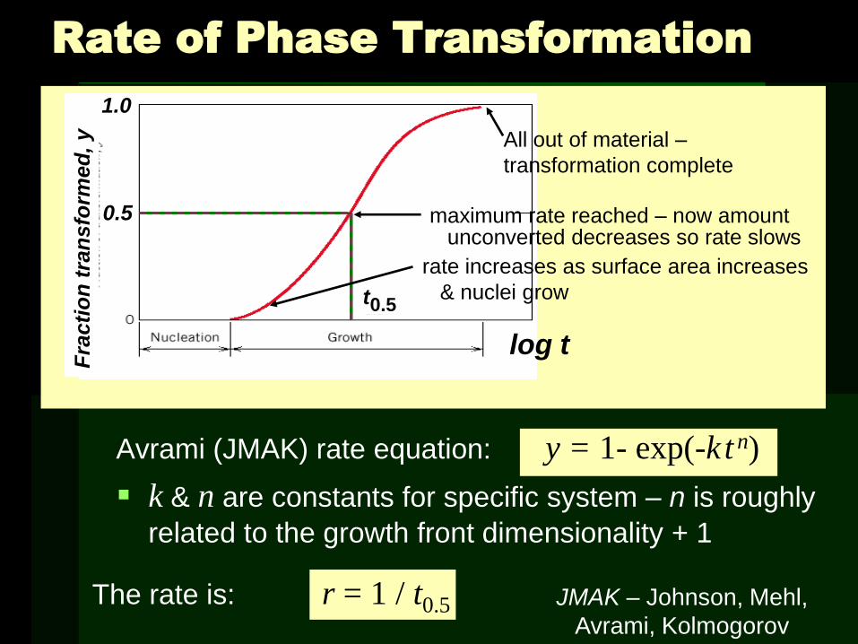
The rate is: r = 1 / t0.5
Avrami (JMAK) rate equation: y = 1- exp(-k t n)
k & n are constants for specific system – n is roughly
related to the growth front dimensionality + 1
Rate of Phase Transformation
All out of material –
transformation complete
log t
Fra
cti
on
tra
nsfo
rmed
, y
Fixed T
maximum rate reached – now amount unconverted decreases so rate slows
0.5
1.0
t0.5 rate increases as surface area increases
& nuclei grow
JMAK – Johnson, Mehl,
Avrami, Kolmogorov

In general, rate increases as T
r = 1/t0.5 = A e -Q/RT
R = gas constant
T = temperature (K)
A = pre-exponential factor
Q = activation energy
Rate of Phase Transformations
• r often small: equilibrium not possible!
135C 119C 113C 102C 88C 43C
1 10 102 104 10
102 104
1
Adapted from Fig.
10.11, Callister 7e.
(Fig. 10.11 adapted
from B.F. Decker and
D. Harker,
"Recrystallization in
Rolled Copper", Trans
AIME, 188, 1950, p.
888.)

Eutectoid Transformation Rate
Course pearlite formed at higher T - softer
Fine pearlite formed at low T - harder
Diffusive flow of C needed
a
a
g g
a
• Growth of pearlite from austenite:
g a a a a
a
a
pearlite growth direction
Austenite (g)
grain boundary
cementite (Fe3C)
Ferrite (a)
g
• Eutectoid
transformation
rate increases
with T. 675°C
(T smaller)
0
50
y (
% p
earlite)
600°C
(T larger) 650°C
100
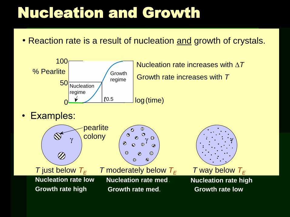
• Reaction rate is a result of nucleation and growth of crystals.
• Examples:
Nucleation and Growth
% Pearlite
0
50
100
Nucleation
regime
Growth
regime
log (time) t 0.5
Nucleation rate increases with T
Growth rate increases with T
T just below TE
Nucleation rate low
Growth rate high
g
pearlite colony
T moderately below TE
g
Nucleation rate med .
Growth rate med.
Nucleation rate high
T way below TE
g
Growth rate low

Transformations & Supercooling
• Can make it occur at: ...727ºC (cool it slowly)
...below 727ºC (“supercool” it!)
• Eutectoid transf. (Fe-C System): g a + Fe3C
0.76 wt% C 0.022 wt% C
6.7 wt% C
Fe
3C
(cem
entite
)
1600
1400
1200
1000
800
600
400 0 1 2 3 4 5 6 6.7
L
g
(austenite)
g +L
g +Fe3C
a +Fe3C
L+Fe3C
d
(Fe) Co , wt%C
1148°C
T(°C)
a
ferrite 727°C
Eutectoid: Equil. Cooling: Ttransf. = 727ºC
T
Supercooling by Ttransf. < 727C
0.7
6
0.0
22

Isothermal Transformation Diagrams
• Fe-C system, Co = 0.76 wt% C
• Transformation at T = 675°C.
100
50
0 1 10 2 10 4
T = 675°C
y,
% tra
nsfo
rmed
time (s)
400
500
600
700
1 10 10 2 10 3 10 4 10 5
Austenite (stable) TE (727C)
Austenite (unstable)
Pearlite
T(°C)
time (s)
isothermal transformation at 675°C

• Eutectoid composition, Co = 0.76 wt% C
• Begin at T > 727°C
• Rapidly cool to 625°C and hold isothermally.
Effect of Cooling History in Fe-C System
400
500
600
700
Austenite (stable) TE (727C)
Austenite
(unstable)
Pearlite
T(°C)
1 10 10 2 10 3 10 4 10 5
time (s)
g g
g
g g
g

Transformations with
Proeutectoid Materials
Hypereutectoid composition – proeutectoid cementite
a
CO = 1.13 wt% C
TE (727°C)
T(°C)
time (s)
A
A
A +
C
P
1 10 102 103 104
500
700
900
600
800
A +
P
Fe
3C
(ce
me
ntite
)
1600
1400
1200
1000
800
600
400 0 1 2 3 4 5 6 6.7
L
g (austenite)
g +L
g +Fe3C
a +Fe3C
L+Fe3C
d
(Fe) Co , wt%C
T(°C)
727°C T
0.7
6
0.0
22
1.1
3

Non-Equilibrium Transformation
Products: Fe-C
• Bainite: (Davenport & Bain) - a strips with long
needles of Fe3C
- diffusion controlled.
• Isothermal Transf. Diagram
Fe3C
(cementite)
5 mm
a (ferrite)
10 10 3
10 5
time (s) 10
-1
400
600
800
T(°C) Austenite (stable)
200
P
B
TE
pearlite/bainite boundary
A
A
100% bainite
100% pearlite
120 mm
cf: Pearlite

- a + grains with spherical
Fe3C
- diffusion dependent.
- heat bainite or pearlite
for long times
(e.g. 18 h at 700°C)
- reduces interfacial area
(driving force)
Spheroidite: Fe-C System
(ferrite)
60 mm
a
(cementite)
Fe3C
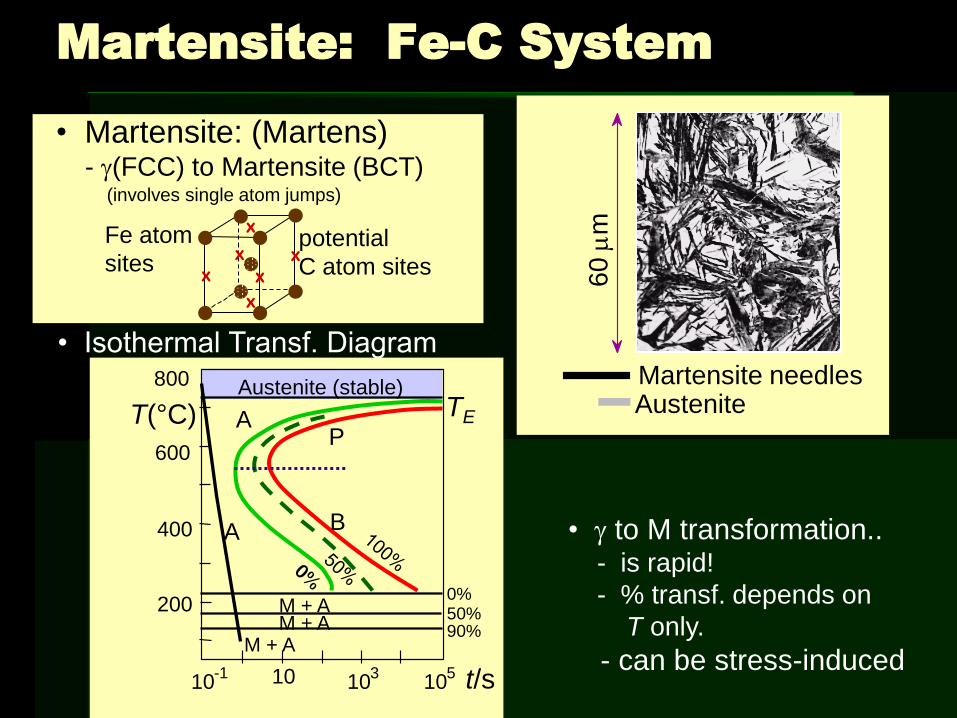
• Martensite: (Martens) - g(FCC) to Martensite (BCT)
• Isothermal Transf. Diagram
• g to M transformation.. - is rapid!
- % transf. depends on
T only.
- can be stress-induced
Martensite: Fe-C System
Martensite needles Austenite
60
mm
10 10 3
10 5 t/s 10
-1
400
600
800
T(°C) Austenite (stable)
200
P
B
TE A
A
M + A M + A
M + A
0% 50% 90%
x
x x
x
x
x potential
C atom sites
Fe atom
sites
(involves single atom jumps)

g (FCC) a (BCC) + Fe3C
Martensite Formation
slow cooling
tempering
quench
M (BCT)
M = martensite is body centered tetragonal (BCT)
Diffusionless transformation BCT if C > 0.15 wt%
BCT few slip planes hard, brittle

Phase Transformations of Alloys
Effect of adding
other elements
Change transition
temp.
Cr, Ni, Mo, Si, Mn
retard
g a + Fe3C
transformation

Dynamic Phase Transformations
On the isothermal transformation diagram
for 0.45 wt% C Fe-C alloy, sketch and label
the time-temperature paths to produce the
following microstructures:
a) 42 % proeutectoid ferrite and 58 % coarse
pearlite
b) 50 % fine pearlite and 50 % bainite
c) 100 % martensite
d) 50 % martensite and 50 % austenite

A + B
A + P
A + a A
B P
A 50%
0
200
400
600
800
0.1 10 103 105 time (s)
M (start)
M (50%)
M (90%)
Example Problem for Co = 0.45 wt%
a) 42 % proeutectoid ferrite and 58 % coarse pearlite (amounts determined by phase diagram)
first make ferrite
then pearlite
coarse pearlite
higher T
T (°C)

a. the amount of pearlite and proeutectoid ferrite (a)
note: amount of pearlite = amount of g just above TE
Co = 0.45wt% C
Ca = 0.022 wt% C
Cpearlite = Cg = 0.76 wt% C
%9.57100x
ag
a
ag
g
CC
CCo
pearlite = 58 %
proeutectoid a = 42 %
Fe
3C
(ce
me
ntite
)
1600
1400
1200
1000
800
600
400 0 1 2 3 4 5 6 6.7
L
g (austenite)
g +L
g + Fe3C
a + Fe3C
L+Fe3C
d
Co , wt% C
1148°C
T(°C)
727°C
CO
R S
Cg Ca
Example Problem for Co = 0.45 wt%

b) 50 % fine
pearlite and
50% bainite
first make pearlite
then bainite
fine pearlite
lower T
T (°C)
A + B
A + P
A + a A
B P
A 50%
0
200
400
600
800
0.1 10 103 105 time (s)
M (start)
M (50%)
M (90%)
Example Problem for Co = 0.45 wt%

A + B
A + P
A + a A
B P
A 50%
0
200
400
600
800
0.1 10 103 105 time (s)
M (start)
M (50%)
M (90%)
Example Problem for Co = 0.45 wt%
c) 100 %
martensite
– quench =
rapid cool
d) 50 % martensite
and 50 %
austenite d)
c)
T (°C)

Mechanical Prop: Fe-C System (1)
• More wt% C: TS and YS increase , %EL decreases.
• Effect of wt% C
Co < 0.76 wt% C
Hypoeutectoid
Pearlite (med) ferrite (soft)
Co > 0.76 wt% C
Hypereutectoid
Pearlite (med)
C ementite (hard)
300
500
700
900
1100
YS
TS(MPa)
wt% C 0 0.5 1
hardness
0.7
6
Hypo Hyper
wt% C 0 0.5 1
0
50
100
%EL
Imp
act e
ne
rgy (
Izo
d, ft
-lb
)
0
40
80
0.7
6
Hypo Hyper
TS
EL
Izod

Mechanical Prop: Fe-C System (2)
• Fine vs coarse pearlite vs spheroidite
• Hardness:
• %RA: fine > coarse > spheroidite
fine < coarse < spheroidite
80
160
240
320
wt%C 0 0.5 1
Bri
ne
ll h
ard
ne
ss fine
pearlite coarse pearlite
spheroidite
Hypo Hyper
0
30
60
90
wt%C D
uctilit
y (
%A
R)
fine pearlite
coarse pearlite
spheroidite
Hypo Hyper
0 0.5 1

Mechanical Prop: Fe-C System (3)
• Fine Pearlite vs Martensite:
• Hardness: fine pearlite << martensite.
0
200
wt% C 0 0.5 1
400
600
Bri
ne
ll h
ard
ne
ss
martensite
fine pearlite
Hypo Hyper

Tempering Martensite
• reduces brittleness of martensite,
• reduces internal stress caused by quenching.
• decreases TS, YS but increases %RA
• produces extremely small Fe3C particles surrounded by a.
9 m
m
MPa
800
1000
1200
1400
1600
1800
30
40
50
60
200 400 600 Tempering T (°C)
%RA
TS
YS
%RA

Summary: Processing Options
Austenite (g)
Bainite (a + Fe3C plates/needles)
Pearlite (a + Fe3C layers + a
proeutectoid phase)
Martensite (BCT phase
diffusionless transformation)
Tempered Martensite (a + very fine
Fe3C particles)
slow cool
moderate cool
rapid quench
reheat
Str
en
gth
Ductilit
y
Martensite T Martensite
bainite fine pearlite
coarse pearlite spheroidite
General Trends