7.1 Gardiner - Remedial grouting works at Upper Rivington ...

SITE SPECIFIC FINAL REPORT Remedial Action at Selected Sites
within the Charlie Area at Fort McClellan, Alabama
PREPARED FOR:
U.S. ARMY ENGINEERING AND SUPPORT CENTER, HUNTSVILLE, ALABAMA
Munitions Response Contract CONUS and OCONUS Contract Number: W912DY-04-D-0011
Delivery Order 0010 Geographical District: Mobile District
PREPARED BY:
Tetra Tech EC, Inc. 4960 Corporate Drive, Suite 140
Huntsville, Alabama 35805
March 2011
The views, opinions, and/or findings contained in this report are those of the author(s) and should not be construed as an official Department of the Army position, policy, or decision,
unless so designated by other documentation.

Contract No. W912DY-04-D-0011 March 2011 Delivery Order 0010 Revision 00
ii
CERTIFICATION
I certify under penalty of law that this document and all attachments were prepared under my direction or supervision according to a system designed to assure that qualified personnel properly gather and evaluate the information submitted. Based on my inquiry of the person or persons who manage the system, or those persons directly responsible for gathering the information, the information submitted is, to the best of my knowledge and belief, true, accurate, and complete. I am aware that there are significant penalties for submitting false information, including the possibility of fine and imprisonment for knowing violations.
Arthur B. Holcomb P.E. Program Manager
Contract No. W912DY-04-D-0011 March 2011 Delivery Order 0010 Revision 00
iii
T AB L E OF C ONT E NT S 1.0 I NT R ODUC T I ON ............................................................................................................ 1-1
1.1 Authorization ....................................................................................................... 1-1 1.2 Objective and Scope ............................................................................................ 1-1 1.3 Site Location ........................................................................................................ 1-2
2.0 DI SC USSI ON .................................................................................................................... 2-1 2.1 Geophysical Prove-Out ........................................................................................ 2-1 2.2 Site Preparation Activities ................................................................................... 2-1
2.2.1 Explosive Magazine Movement................................................................ 2-1 2.2.2 Location Surveys ...................................................................................... 2-2 2.2.3 Surface Clearance .................................................................................... 2-2 2.2.4 Brush Clearance ...................................................................................... 2-3
2.3 Tire House Removal ............................................................................................ 2-3 2.4 Storm Drainage Pipe and Culvert Removal ......................................................... 2-4 2.5 Firing Point Emplacements .................................................................................. 2-4 2.6 Target Emplacements........................................................................................... 2-4 2.7 Geophysical Mapping .......................................................................................... 2-4
2.7.1 Data Acquisition ...................................................................................... 2-4 2.7.2 Data Processing and Interpretation ........................................................ 2-5
2.8 Anomaly Reacquisition ........................................................................................ 2-6 2.9 MEC Intrusive Operations ................................................................................... 2-6
2.9.1 DGM Intrusive Operations ...................................................................... 2-6 2.9.2 Analog Intrusive Operations .................................................................... 2-7 2.9.3 Disposition/Disposal of MPPEH ............................................................. 2-8 2.9.4 MEC Disposal ........................................................................................ 2-10
2.10 Demobilization ................................................................................................... 2-14
3.0 DOC UM E NT A T I ON........................................................................................................ 3-1 3.1 Maps ..................................................................................................................... 3-1 3.2 Reacquisition Sheets (Dig Sheets) ....................................................................... 3-1 3.3 Grid Maps ............................................................................................................ 3-1 3.4 Daily Site Activity Reports .................................................................................. 3-1 3.5 Site QC Documentation ....................................................................................... 3-1 3.6 Site QA Documentation ....................................................................................... 3-1 3.7 Explosives Accountability Records ..................................................................... 3-1 3.8 Photographs.......................................................................................................... 3-1
4.0 L E SSONS L E A R NE D ...................................................................................................... 4-1
5.0 QUA L I T Y A C T I V I T I E S / T E ST S .................................................................................. 5-1 5.1 Quality Control (QC)/Quality Assurance (QA) ................................................... 5-1 5.2 Tier 1 QC process-Training ................................................................................. 5-1
5.2.1 Preparatory Phase Inspections ................................................................ 5-1 5.2.2 Analog Operator Instrument Proficiency Test ......................................... 5-2 5.2.3 Geophysical Proveout .............................................................................. 5-2
5.3 Tier 2 QC Process- Process Quality Control ....................................................... 5-2 5.3.1 Initial Phase Inspections .......................................................................... 5-2

Contract No. W912DY-04-D-0011 March 2011 Delivery Order 0010 Revision 00
iv
5.3.2 Follow-Up Phase Inspections .................................................................. 5-3 5.3.3 Daily Instrument Test Strip ...................................................................... 5-3 5.3.4 Blind Seeding ........................................................................................... 5-3 5.3.5 Geophysical Field QC Procedures .......................................................... 5-4 5.3.6 Internal and External Geophysical Quality Process Checks ................... 5-5
5.4 Tier 3 Product QC ................................................................................................ 5-5 5.5 Results of Quality Control ................................................................................... 5-6 5.6 USAESCH Quality Assurance ............................................................................. 5-6
6.0 F I NA NC I A L B R E A K DOW N .......................................................................................... 6-1
7.0 SUM M A R Y A ND C ONC L USI ON ................................................................................. 7-1
8.0 R E F E R E NC E S.................................................................................................................. 8-1
9.0 F I G UR E S-SI T E M A PS .................................................................................................... 9-1
10.0 R E SPONSE S T O C OM M E NT S ................................................................................... 10-1
List of Tables Table 2-1 Tire House Analytical Results ..................................................................................... 2-3Table 2-2 Results of Intrusive Investigation ................................................................................ 2-8Table 2-3 Munition /Range Related/Cultural Debris Recovered ................................................. 2-9Table 2-4 Total Anomaly Type by Category ............................................................................... 2-9Table 2-5 Results of Investigation by Area ............................................................................... 2-10Table 5-1 Daily Instrument Test Strip ......................................................................................... 5-3Table 5-2 Project CAR/DN/NCR ................................................................................................ 5-6Table 5-3 Form 948s .................................................................................................................... 5-7Table 7-1 Project Summary ......................................................................................................... 7-1
List of Appendices Appendix A Appendix A-1 Statement of Work
Appendix A-2 Final Work Plan Appendix A-3 Explosives Safety Submission (ESS)
Appendix B Appendix B-1 Geophysical Prove-Out Documentation
Appendix B-2 Geophysical Maps Field Appendix B-3 Geophysical Dig Data Appendix B-4 Geophysical Field Note Sheets Appendix B-5 USAESCH QA Mapping Data Acceptance Appendix C Appendix C-1 All Intrusive Anomaly Results Appendix D Appendix D-1 Daily Site/SUXOS Activity Reports Appendix D-2 Quality Control Documentation Appendix D-2a Daily Quality Control Reports
Appendix D-2b QC 3 Phase Inspection Reports Appendix D-2c QC Product Inspection Reports
Contract No. W912DY-04-D-0011 March 2011 Delivery Order 0010 Revision 00
vi
Acronym List 2D Two Dimensional AEDA Ammunition, Explosives and Dangerous Articles AGM Analog Geophysical Mapping ANSI American National Standards Institute APP Accident Prevention Plan AR Army Regulation ARARs Applicable and Relevant and Appropriate Requirements ASQ American Society of Quality ATFE Bureau of Alcohol, Tobacco, Firearms and Explosives BIP Blow in Place BRAC Base Realignment and Closure CD Cultural Debris CERCLA Comprehensive Environmental Response, Compensation, and Liability Act CFR Code of Federal Regulations CO Contracting Officer COC Chain of Custody CRL Corporate Reference Library CWM Chemical Warfare Materiel CY Cubic Yards DA Department of the Army DAS Data Acquisition Specialists DDESB Department of Defense Explosive Safety Board DFW Definable Feature of Work DGM Digital Geophysical Mapping DGPS Differential Global Positioning System DID Data Item Description DMM Discarded Military Munitions DOD Department of Defense DOT Department of Transportation DS Demolition Supervisor EC Engineering Control EHS Environmental, Health and Safety EM Engineer Manual also Electromagnetic EOD Explosive Ordnance Disposal EP Engineer Pamphlet EPP Environmental Protection Plan ER Engineer Regulation ESRI Environmental Systems Research Institute ESS Explosive Safety Submission EZ Exclusion Zone FAR Federal Acquisition Regulation FCR Field Change Request FM Titanium tetrachloride FTL Field Team Leader FTP File Transfer Protocol GFP Government Furnished Property GIS Geographic Information System GPO Geophysical Prove-out GPS Global Positioning System GSA General Services Administration GTM Geophysical Task Manager GVW Gross Vehicle Weight

Contract No. W912DY-04-D-0011 March 2011 Delivery Order 0010 Revision 00
vii
HARC Historic, Archeological and Cultural HAZWOPER Hazardous Waste Operations & Emergency Response HD Hazard Class Designation HE High Explosive HERO Hazard of Electromagnetic Radiation to Ordnance HFD Hazardous Fragment Distance IAW In accordance with ID Identification LDD Loss, damage, or destruction LPC Lakewood Processing Center MC Munitions Constituents MD Munitions Debris MDAH Material Designated As Hazardous MDAS Material Designated As Safe MEC Munitions and Explosives of Concern MEL Maintenance Expenditure Limits MGFD Munition with the Greatest Fragmentation Distance (replaces MPM) MK Mark MLNWR Mountain Longleaf National Wildlife Refuge mm Millimeter MP Man-portable MPPEH Material Potentially Presenting An Explosive Hazard MR Munitions Response MRC Multiple Round Container MRR Material Received Report MS Microsoft MSD Minimum Separation Distance MSDS Material Safety Data Sheet MSL Mean Sea Level mV Millivolt NCP National Contingency Plan NCR Nonconformance Report NEW Net Explosive Weight O&M Operations & Maintenance OE Ordnance/Explosive OSHA Occupational Safety and Health Administration PA Purchasing Agent PCMCIA Personal Computer Memory Card International Association PEL Permissible Exposure Limit PESM Project Environmental and Safety Manager PLS Professional Land Surveyor PM Project Manager PO Purchase Order POC Point of Contact PPE Personal Protective Equipment PR Purchase Requisition PWS Performance Work Statement QA Quality Assurance QC Quality Control QPM Quality Program Manual RA Remedial Action RAM Random Access Memory RBC Risk Based Criteria RCRA Resource Conservation and Recovery Act

Contract No. W912DY-04-D-0011 March 2011 Delivery Order 0010 Revision 00
viii
RCWM Recovered Chemical Warfare Material RMP Risk Management Plan RTS Robotic Total Station SDSFIE Spatial Data Standards for Facilities Infrastructure and Environment SDTS Spatial Data Transfer Standard SG Site Geophysicist SOP Standard Operating Procedure SSFR Site Specific Final Report SUXOS Senior UXO Supervisor TBC To Be Considered TCLP Toxicity Characteristic Leaching Procedure TDEM Time Domain Electromagnetic TEU U.S. Army Technical Escort Unit TIF Tagged Image File TIP Task Initiation Procedures TM Technical Manual TSCA Toxic Substances Control Act TtEC Tetra Tech EC, Inc. USACE U.S. Army Corps of Engineers USAESCH U.S. Army Engineering and Support Center, Huntsville USFWS United States Fish and Wildlife Service UTM Universal Transverse Mercator UXO Unexploded Ordnance UXOSO UXO Safety Officer UXOSP UXO Sweep Personnel UXOQC UXO Quality Control Specialist WDCMP Work, Data, and Cost Management Plan WP White Phosphorus

Contract No. W912DY-04-D-0011 March 2011 Delivery Order 0010 Revision 00
1-1
1.0 I NT R ODUC T I ON
1.0.1 This Site Specific Final Report (SSFR) for the Remedial Action of selected sites within the Charlie Area was prepared for U.S. Army Engineering and Support Center, Huntsville (USAESCH) in accordance with Data Item Description (DID) MR-030. Fort McClellan is a U.S. Army facility under control of the Base Realignment and Closure (BRAC) Division, Assistant Chief of Staff for Installation Management, Headquarters, and Department of the Army and was closed under the BRAC program. Material Potentially Presenting an Explosive Hazard (MPPEH),are known to exist on parts of this property.
1.1 A UT H OR I ZAT I ON
1.1.1 This project was authorized on October 10, 2008 as Task Order 0010, under Contract, W912DY-04-D-0011, Charlie Area Remedial Action, Fort McClellan, Alabama by the US Army Engineering Support Center, Huntsville. Fort McClellan is a former U. S. Army facility that was under control of the U. S. Army Training and Doctrine Command and was closed by the BRAC program in 1999. This Munitions and Explosives of Concern (MEC) Remedial Action was performed in a manner consistent with the Comprehensive Environmental Response, Compensation, and Liability Act (CERCLA) and the National Contingency Plan (NCP). Therefore, no Federal, State, or Local permits were required or obtained; although the substantive permit requirements were fulfilled. The provisions of 29 Code of Federal Regulations (CFR) 1910.120 Hazardous Waste Operations and Emergency Response applied to all actions on the project site. The project has been executed in accordance with the government-furnished performance work statement (PWS), approved Work Plan, technical instructions, and other contract direction. A copy of the PWS is contained in Appendix A-1. The original PWS that was provided with the award was dated June 26, 2008. The PWS was modified eight times with the final version dated April 08, 2010. TtEC prepared and submitted a Final Site-Specific Work Plan for Remedial Action (RA) (TtEC, 2009) in February 2009 and received notice to proceed on March 27, 2009. A copy of the Final Site-Specific Work Plan is contained in Appendix A-2.
1.2 OB J E C T I V E A ND SC OPE
1.2.1 The objective of this task order was to provide all Munitions Response (MR) services necessary to accomplish Remedial Action at the selected sites within the Charlie Area in Fort McClellan, AL. The selected sites totaling 239.71 acres are as follows:
a) 81mm Mortar Range (Area Alpha) – 5.7 acres – Clearance to Depth of Detection b) Bains Gap Road Ranges (Area Bravo) – 36.7 acres – Clearance to Depth of Detection c) Range 20 (Area Charlie) – 25.5 acres – Clearance to Depth of Detection d) Range 24A (Area Delta) – 66.9 acres total;
a. 12.55 acres- Surface Clearance Only b. Remaining 54.35 acres - Clearance to Depth of Detection
e) Priority Area 1 (Area Echo) – 44.41 acres – Clearance to Depth of Detection

Contract No. W912DY-04-D-0011 March 2011 Delivery Order 0010 Revision 00
1-2
f) Priority Area 1a (Area Foxtrot) – 28.1 acres – Clearance to Depth of Detection g) Priority Area 3 (Area Golf) – 11.4 acres – Clearance to Depth of Detection h) Priority Area 4 (Area Hotel) – 21 acres – Clearance to Depth of Detection
The listed areas that required a Remedial Action can be seen in Section 9.
1.2.2 The PWS associated with this Task Order included the following additional services to be performed in conjunction with the Remedial Action activities:
• Removal and clearance of Foundation & Debris Areas located in Range 24a
• Removal and clearance of 30 Storm Drainage Pipe & Culverts located throughout the Charlie Area
• Removal and clearance of Firing Point & Drainage Pipes located in the Bains Gap Range Area
• Removal and clearance of targets & target structures located in the Priority 1 Area
1.3 SI T E L OC AT I ON
1.3.1 Fort McClellan is located northeast of the City of Anniston, Calhoun County, Alabama. To the west of the Fort are the areas known as Weaver and Blue Mountain. To the north is the City of Jacksonville. The Talladega Forest is located east of the Fort. The portion of Fort McClellan to be addressed in this SSFR has been previously designated the Charlie Area, and lies in the eastern portion of the facility, east of the main cantonment area. The Charlie Area is comprised of portions of the Choccolocco Mountains and the Choccolocco Corridor to the east of the mountains. The Charlie Area, with the exception of the Choccolocco Corridor portion which is owned by the State of Alabama, has been transferred to the Department of the Interior for management by the Fish and Wildlife Service as a wildlife refuge, the Mountain Longleaf National Wildlife Refuge (MLNWR). The MEC Clearance Overview map which depicts the location of Fort McClellan with the 8 selected Areas is located in Section 9.
Contract No. W912DY-04-D-0011 March 2011 Delivery Order 0010 Revision 00
2-1
2.0 DI SC USSI ON
2.0.1 Field work began on March 30, 2009 with the mobilization of personnel and equipment to the site. At the cessation of field activities on April 10th, 2010 the objective of performing a Remedial Action to reduce the risk of Material Potentially Presenting an Explosive Hazard (MPPEH) on the selected sites listed in section 1.2.1 was accomplished. Munition Response activities were conducted on fourteen hundred and forty seven (1447) full and partial grids containing approximately 239.71 acres. A total of 227.16 acres were cleared of MPPEH to the depth of detection and 12.55 acres were surface cleared of potential MPPEH as outlined in the PWS contained in Appendix A-1. All munition response field activities including site preparation, geophysical mapping, anomaly reacquisition, and intrusive operations are described in this chapter. Quality Control and Quality Assurance are discussed in Chapter 5.0.
2.1 G E OPH Y SI C A L PR OV E -OUT
2.1.1 Prior to performing the geophysical mapping at the project site, TtEC performed the Geophysical Prove-Out (GPO) at Fort McClellan between April 10th and April 16th, 2009. The objective of the GPO was to demonstrate and document the performance of the data acquisition methodology, spatial sampling protocols, sensor(s) and positioning equipment, data analysis and management systems, data transfer procedures, and the geophysical Quality Control (QC) and Quality Assurance (QA) system. A copy of the final GPO Letter Report is contained in Appendix B-1. TtEC successfully demonstrated the capability of the geophysical equipment, procedures and personnel to be used for the geophysical survey and established the methodology of the mapping survey IAW DID MR-005-01.
2.1.2 TtEC performed an Operator Proficiency Test on all project personnel performing Analog “EM & Dig” operations to demonstrate and document the performance of the individual instrument operators and to ensure they were capable of meeting the overall project objectives. All operators demonstrated proficiency to conduct project operations.
2.2 SI T E PR E PA R AT I ON A C T I V I T I E S
2.2.1 Explosive Magazine Movement
2.2.1.1 TtEC was tasked with moving the two USAESCH owned ATF-approved Type II, single compartment, portable magazines from their previous location adjacent to Range 20 to an area north of the Bains Gap Road Ranges. The exact location of the Magazines is shown in the Explosive Safety Submission contained in Appendix A-3. The magazines along with the security fence and grounding system were setup and tested IAW DA Pam 385-64 on April 09, 2009. Aker Electric Company Inc. conducted the test of the magazines earth electrode (ground) system but the results were higher than the requirements allowed “≈ 50 ohms”. Acker Electric was contracted to design the new earth electrode subsystem (ground) system and made the following modifications;
o Installation of a new larger diameter bare copper ground loop system placed outside the fence but tied into the original ground loop system;

Contract No. W912DY-04-D-0011 March 2011 Delivery Order 0010 Revision 00
2-2
o The copper ground probes were spaced every 20 ft with the locations running east to west, north to south, and southwest to northeast and tied into the new ground loop system placed outside the fence.
2.2.1.2 On 4/24/09 Acker Electric completed the modification to the explosive magazines electrical grounding system and conducted the three point drop of potential test with a result of a 12 ohms reading. The 12 ohms reading was well below the not to exceed 25 ohms requirement per Chapter 6 of DAPAM 385-64. Additionally both magazines passed the bonding test with results of .4 ohms for magazine 1 and .8 ohms for magazine 2. The requirement per Chapter 6 of DAPAM 385-64 is ≤ 1 ohms. The results of the magazine testing are contained in Appendix F-4.
2.2.2 Location Surveys
2.2.2.1 Boundary/Grid Setout. The boundary and grid corner setout was conducted by a Registered Land Surveyor (RLS) (Tetra Tech, Orlando, Florida, Alabama License Number 29414-S). All work was carried out in accordance with the requirements outlined in DID MR-005-07.01 and the “Minimum Technical Standards for the Practice of Land Surveying in the State of Alabama”. All coordinates were based on the State Plane Grid System to the North American Datum of 1983 (NAD83). A grid numbering system unique to each area was established, and a network of 100 ft. × 100 ft. grids was laid within the surveyed boundaries. Some nonstandard size grids were installed in order to accommodate the various shapes, challenging topography and terrain of the areas selected for the RA. TtEC UXO Technicians provided anomaly avoidance for the survey crew in order to ensure that each survey location was clear of sub-surface anomalies. A copy of the Survey Operations Summary Report is contained in Appendix F-1.
2.2.3 Surface Clearance
2.2.3.1 Surface clearance activities were conducted prior to brush cutting and DGM operations in all the selected project areas. Personnel searched each grid using standard detector-aided visual surface clearance procedures while operating a Schonstedt Model 52CX ordnance locator. The surface clearance teams used the line abreast method, removing all metallic objects located on the surface of the ground. This method involves team members walking side by side, separated by a distance that does not exceed visual coverage of the adjoining person’s field of view, visually scanning the surface terrain while systematically using the hand-held magnetometer to assist in finding metallic items. Pin Flags were placed at the ends of the surface clearance teams line to aid the team in walking a straight line, and the person on the end of the sweep line used the pin flags as a guide until the team reached the edge of the grid, then the pin flags were moved over to be used on the next pass. In areas where this approach did not work or adequate coverage could not be maintained, the grid was then subdivided into lanes or sub-grids using rope to ensure complete coverage. This procedure was repeated until the entire grid had been searched. A total of 14 MEC items were recovered and disposed of while conducting surface clearance operations on the 8 selected areas. All cultural and target debris within the defined project area was removed, all other material removed (e.g. Munition Debris, Small Arms) was inspected and verified to be free of explosive hazards. Surface clearance personnel did not perform intrusive activities. No intrusive efforts were made to remove suspect items entirely below the ground surface.
Contract No. W912DY-04-D-0011 March 2011 Delivery Order 0010 Revision 00
2-3
A 12.55 acre portion of Range 24A was identified as a sensitive area by USFWS and a surface clearance only operation was performed on that portion of Range 24A due to the presence of possible archeological resources, wetlands, seeps, and springs located in the area. Due to the residual risk of subsurface ordnance, Land Use Controls will be required for the 12.55 acre area. Future Land Use Controls will be described in the Charlie area EECA report which will be prepared by others under a separate contract.
A copy of the Range24a Surface Clearance Report is contained in Appendix F-3.
2.2.4 Brush Clearance 2.2.4.1 Brush clearance was conducted in all the accessible areas of the selected project areas. The brush was cut as low as possible to permit the best quality data during subsequent geophysical activities. With the exception of longleaf pine trees, trees measuring less than 4-inches in diameter at chest level were removed. As few longleaf pine trees as possible, including those less than 4 inches, were disturbed while preparing the site for the removal action. Brush and grass were trimmed 4-6 inches above the ground surface when necessary to facilitate data collection in the area. The vegetation removed was chipped/shredded and re-dispersed on site except for the Seep Area located in a portion of the Priority 1 Clearance Area shown in Figure 6. The Seep Area was classified as a Special Interest Natural Area (SINA) and required the brush clearance activities to be conducted by hand. Teams working within the SINA were restricted from operating vehicles or using heavy equipment to conduct brush clearance activities. Only hand carried or hand held equipment were used. The brush clearance activities were escorted by a qualified UXO Technician.
2.3 T I R E H OUSE R E M OVA L
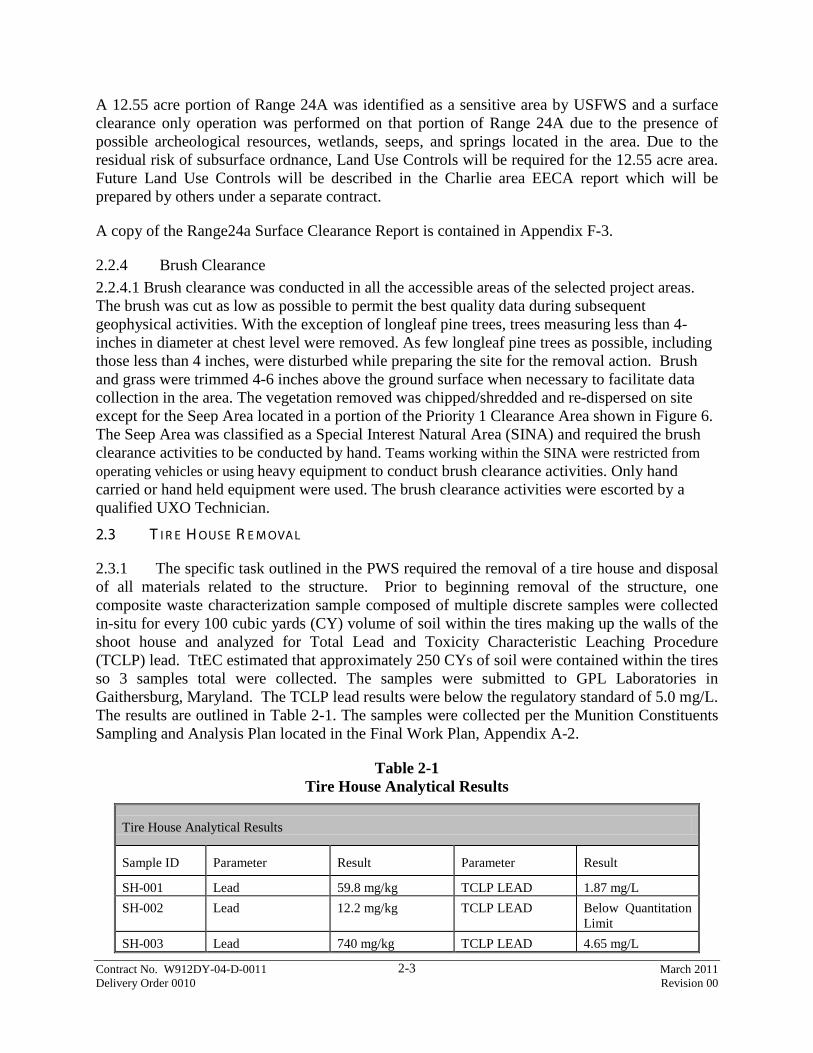
2.3.1 The specific task outlined in the PWS required the removal of a tire house and disposal of all materials related to the structure. Prior to beginning removal of the structure, one composite waste characterization sample composed of multiple discrete samples were collected in-situ for every 100 cubic yards (CY) volume of soil within the tires making up the walls of the shoot house and analyzed for Total Lead and Toxicity Characteristic Leaching Procedure (TCLP) lead. TtEC estimated that approximately 250 CYs of soil were contained within the tires so 3 samples total were collected. The samples were submitted to GPL Laboratories in Gaithersburg, Maryland. The TCLP lead results were below the regulatory standard of 5.0 mg/L. The results are outlined in Table 2-1. The samples were collected per the Munition Constituents Sampling and Analysis Plan located in the Final Work Plan, Appendix A-2.
Table 2-1 Tire House Analytical Results
Tire House Analytical Results
Sample ID Parameter Result Parameter Result
SH-001 Lead 59.8 mg/kg TCLP LEAD 1.87 mg/L SH-002 Lead 12.2 mg/kg TCLP LEAD Below Quantitation
Limit SH-003 Lead 740 mg/kg TCLP LEAD 4.65 mg/L
Contract No. W912DY-04-D-0011 March 2011 Delivery Order 0010 Revision 00
2-4
2.3.2 Following confirmation that lead levels were below the regulatory limits, TtEC used heavy equipment to collapse the walls of the tire house by pushing the tires towards the center of the facility. UXO Technicians segregated and inspected the tires for MPPEH while removing soil prior to placement in roll-off containers. The tires were collected and disposed of by Waste Corporation of Alabama at the Fines Landfill located in Alpine, AL. Since the TCLP lead results were below the regulatory standard of 5.0 mg/L the soil was disposed of on site by spreading it out on the footprint of the tire house. The footprint was then geophysically mapped and any anomalies that met the projects anomaly selection criteria were intrusively investigated as part of the Bains Gap Range MEC removal. A copy of the Tire House Disposal Summary Report is attached in Appendix F-2.
2.4 ST OR M DR A I NA G E PI PE A ND C UL V E R T R E M OVA L
2.4.1 TtEC removed 30 storm drainage pipe/culvert structures located in the Charlie Area and conducted Analog “EM & Dig” operations on the footprint of the structures. The coordinates for the location of the structures were supplied by USAESCH and surveyed in by the Registered Land Surveyor. The location of the 30 storm drainage pipe/culvert structures are depicted on the figures located in Appendix F-1 Survey Operations Summary Report.
2.5 F I R I NG POI NT E M PL A C E M E NT S
2.5.1 TtEC removed 54 concrete firing point emplacements and associated steel corrugated storm drainage structures that were located in the northwest portion of the Bains Gap Range and continued across the southwest portion of the Priority 1a area. The firing points and drainage structures were removed by mechanical excavation and the foot print was cleared by conducting Analog “EM & Dig” operations.
2.6 T A R G E T E M PL A C E M E NT S
2.6.1 TtEC removed 199 pop-up targets and target structures located throughout the Priority 1 area. The pop-up targets and target structures were removed by mechanical excavation and the foot print was cleared by conducting Analog “EM & Dig” operations.
2.7 G E OPH Y SI C A L M A PPI NG
2.7.1 Data Acquisition
2.7.1.1 A geophysical survey using digital geophysical mapping (DGM) techniques was performed at each of the eight sites in accordance with the requirements specified in the PWS, SSWP, DID MR-005-05.01. The methodologies and processes used to collect data were demonstrated at the GPO and were approved by USAESCH prior to conducting the geophysical survey at these sites. Geophysical data was collected utilizing a Time Domain Electromagnetic (TDEM) method utilizing the EM61-MK2 manufactured by Geonics LTD. The EM61-MK2 system was used in conjunction with a Leica System 1200 Robotic Total Station (RTS) for positional data within most of the project areas. At some of the grids within Range 20, positional data was determined using the Metris iGPS (laser based system formerly named the Constellation). This system was used for a short period and was taken out of service due to
Contract No. W912DY-04-D-0011 March 2011 Delivery Order 0010 Revision 00
2-5
below average production of the data acquisition team as a result of the iGPS sensitivity to moisture.
2.7.1.2 All areas with the exception of the Surface Clearance only area located in Range 24a that were safely accessible to the two or three person DGM team were geophysically mapped. Each area was mapped using a line spacing of 2 foot to 2.5 foot and an in-line sample spacing of approximately 4 to 5 inches. The areas that were not mapped with DGM were investigated using Analog “EM & Dig” techniques (Section 2.9.2). These areas included areas that were too steep (greater than 40% slope) such as mountain sides, creek beds or areas where obstacles prevented the collection of mapping data. Each area that was cleared with the “EM & Dig” techniques is delineated on the geophysical maps located in Appendix B-2. Geophysical QC procedures are discussed in Section 5.3.5.
2.7.2 Data Processing and Interpretation
2.7.2.1 All data was processed and analyzed in accordance with the requirements specified in the PWS, SSWP, DID MR-005-05.01 and the approved GPO Letter Report located in Appendix B-1. Geophysical measurements and position data was stored on digital media during data acquisition. Each day the acquisition data was transferred to the processing center for data processing and evaluation. A TtEC geophysicist performed geophysical and position data processing and QC checks. Processing of the data was performed with internally developed software that has been specifically produced to integrate and assess digital geophysical data acquired with the RTS and iGPS positioning systems. The processing included such steps as merging of EM and position data, instrument bias removal, and instrument latency corrections. These processed data were output to Geosoft Oasis Montaj Mapping software (version 7.1) for QC, analysis, and to create color-coded images of sensor intensity for interpretation. Some re-interpolation of the data was performed within Montaj if the initial merging did not correctly position the data due to walking pace irregularities. Sensor drift corrections were also performed within Montaj. Data was recorded in Alabama East State Plane NAD83 (feet) coordinate system. All data processing parameters were stored in digital files (*.chk) and in the Oasis Montaj log file (*.log).
2.7.2.2 Minimum target selection criteria were based on the smallest MEC object known to have been recovered in the project area site, which was the 37mm projectile. Initial criteria were determined during the GPO. The horizontal 37mm at 15 inches was the smallest signature item to use for a lower threshold for “digs” at the Bains Gap Ranges, Range 20, and Range 24A, Priority Areas 1, 1A, 3, and 4 areas. While it is not possible in all cases to exactly quantify the interpretation criteria due to the complex interrelationships between the data characteristics (signal intensity, acquisition path geometry, anomaly shape, influence of surrounding anomalies) and the influence of the site characteristics (topography, vegetation, cultural features), the following general guidelines were implemented during the interpretation process to select targets for excavation:
• Channel 2_366 time gate signal intensity > 4 mV above the local background
• Anomaly apparent on minimum of two adjacent data acquisition transects

Contract No. W912DY-04-D-0011 March 2011 Delivery Order 0010 Revision 00
2-6
2.7.2.3 At the 81mm Range, the target of interest was the 81mm mortar. TtEC based it’s criteria on the new GPO, the old GPO at Fort McClellan, on GPOs at other locations, and on previous experience. The selection criteria for the 81mm Range was any targets that appear on a minimum of 3 data acquisition lines with a response of at least 12 mV on the 366 us time gate and/or 20 mV on the 216 us time gate.
2.7.2.4 Processed EM61 data was presented on individual (by grid) color-contour maps, where the color contours represent the signal intensity. The locations of anomalies selected for reacquisition are indicated on the maps. These anomaly maps are included in Appendix B-2. The interpreted anomaly data were digitally exported to a *.csv file and uploaded to the Project Microsoft Access database. The dig sheet data was organized by grid, and contain a unique anomaly identifier for each target selection, its x-y coordinate location, signal intensity value(s) from the EM61 MKII, and dig priority. Comments such as “geology?”, “small” or “noise?” are used to describe anomalies that are generally not representative of the anomaly selection criteria and were included on the dig sheets.
2.8 A NOM A L Y R E A C QUI SI T I ON
2.8.1 Anomaly reacquisition teams successfully processed through the GPO prior to conducting anomaly reacquisition operations. A two-man team using the RTS performed anomaly reacquisition concurrently with other site activities. The procedure for reacquiring the location of the anomalies was to obtain the state plane coordinates of the anomalies in question from the geophysically interpreted dig sheets and load the target anomalies onto the positioning system in the correct format and place a non-metallic pin flag marked with the unique anomaly identification (ID) with a indelible pen at the target location. The positioning system was checked for proper coordinate location by reacquiring and comparing (in the field) a minimum of one known grid corner prior to reacquiring any anomaly locations within the grid. This procedure allowed for early identification of potential errors in the reacquire process. A total of 20,665 geophysical anomalies were reacquired.
2.9 M E C I NT R USI V E OPE R AT I ONS
2.9.1 DGM Intrusive Operations
2.9.1.1 The objective of the DGM intrusive operations was to investigate the flagged anomaly locations in areas where geophysical mapping was performed. The following paragraphs explain the intrusive excavation process.
2.9.1.2 The Senior UXO Supervisor (SUXOS) planned the work location of the intrusive team taking into account availability of dig sheets, equipment availability and the required exclusion zones and team separation distances. After the morning safety brief each day, the SUXOS allocated individual grids and documentation to the intrusive team leader for their days work.
2.9.1.3 After intrusive teams had received their briefings and conducted their daily vehicle inspections and daily equipment checks in the instrument test strip, the intrusive team mobilized to the work-site. The project team verified no unauthorized personnel were present within the exclusion zones. Once verified the SUXOS proceeded to give the intrusive teams authorization to commence intrusive operations for the day.

Contract No. W912DY-04-D-0011 March 2011 Delivery Order 0010 Revision 00
2-7
2.9.1.4 Within each grid, the intrusive team leader directed the intrusive team members to excavate anomaly flags. The intrusive team utilized a combination of the White XLT and Vallon handheld instruments to initially excavate the flagged target location. Once the initial investigation removed the target of interest from the anomaly location the target location was rechecked with the EM-61. The following steps outline the operational use of the EM61 as it was utilized as a geophysical instrument on the intrusive team.
1. The operators verified they were free of metal that may impact the instrument. 2. The EM61 was warmed up for a minimum of 5 minutes.
a. The warm-up period was repeated if it was turned off for any period of time. b. The background readings were checked in a quiet area near target location as
shown on the geophysical maps as a green area prior to checking each target. Operators would find an area where the EM61 values didn’t vary much when moving the EM61 around. The values did not have to be equal to zero, but they shouldn’t have varied much during movement when trying to find geologically clean area. The operator would then place a colored stake at that location to mark nulling location and note approximate location on map.
3. Once the appropriate area for the null was found the operator would then null the EM61. a. For any subsequent renulling the operator would return to that staked location
while checking the target anomalies within that grid or series of grids. 4. The operator would check the hole by moving the EM61 over the target location
completely covering the target footprint while looking for the maximum reading on the 2nd channel (366us).
5. Record the maximum reading. 6. If the value of the reading is greater than the action level, additional excavation at the
target location is performed until mV reading fall below the action level. 7. If obstruction (tree, brush, rocks) prevented covering the area and could not be removed,
the Vallon would be used to check the target location.
2.9.1.5 As each anomaly was excavated, the team leader recorded the items found at each anomaly flag. A geophysical map and hardcopy dig sheet were continuously reviewed to ensure that the correct number of anomalies was excavated. In the instance where an anomaly flag had been displaced or was missing, the SUXOS was contacted and the anomaly reacquisition team replaced the anomaly flag. The intrusive teams prosecuted 20,665 flagged anomalies which took approximately 54,269 total digs to clear the footprint of the target. The intrusive results for all of the select areas are located in Appendix C-1.
2.9.2 Analog Intrusive Operations
2.9.2.1 There were areas in each of the 8 selected sites that were not geophysically mapped due to the characteristics of the terrain (e.g. slope, obstructions) that precluded safely carrying the EM-61 coil. There were also “high density” areas that were geophysically mapped but the geophysicists could not make target selections due to significant metallic signature of the area. The geophysicist would output to the reacquire team coordinates for multiple points to delineate the boundary of the Analog “EM & Dig” areas. The reacquire team would then install these points utilizing the RTS and mark the Analog “EM & Dig” area with non-metallic pin flags. The non-metallic pin flags were a different color than the pin flags used to mark target anomaly locations. These areas were then cleared using an Analog “EM & Dig” protocol utilizing
Contract No. W912DY-04-D-0011 March 2011 Delivery Order 0010 Revision 00
2-8
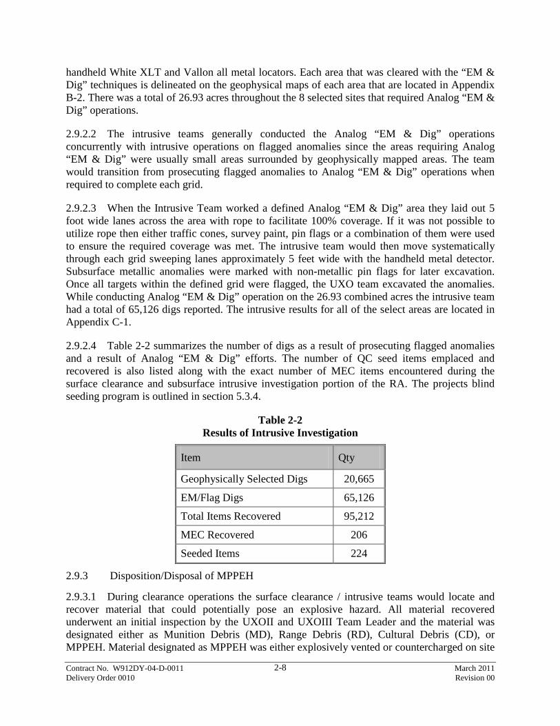
handheld White XLT and Vallon all metal locators. Each area that was cleared with the “EM & Dig” techniques is delineated on the geophysical maps of each area that are located in Appendix B-2. There was a total of 26.93 acres throughout the 8 selected sites that required Analog “EM & Dig” operations.
2.9.2.2 The intrusive teams generally conducted the Analog “EM & Dig” operations concurrently with intrusive operations on flagged anomalies since the areas requiring Analog “EM & Dig” were usually small areas surrounded by geophysically mapped areas. The team would transition from prosecuting flagged anomalies to Analog “EM & Dig” operations when required to complete each grid.
2.9.2.3 When the Intrusive Team worked a defined Analog “EM & Dig” area they laid out 5 foot wide lanes across the area with rope to facilitate 100% coverage. If it was not possible to utilize rope then either traffic cones, survey paint, pin flags or a combination of them were used to ensure the required coverage was met. The intrusive team would then move systematically through each grid sweeping lanes approximately 5 feet wide with the handheld metal detector. Subsurface metallic anomalies were marked with non-metallic pin flags for later excavation. Once all targets within the defined grid were flagged, the UXO team excavated the anomalies. While conducting Analog “EM & Dig” operation on the 26.93 combined acres the intrusive team had a total of 65,126 digs reported. The intrusive results for all of the select areas are located in Appendix C-1.
2.9.2.4 Table 2-2 summarizes the number of digs as a result of prosecuting flagged anomalies and a result of Analog “EM & Dig” efforts. The number of QC seed items emplaced and recovered is also listed along with the exact number of MEC items encountered during the surface clearance and subsurface intrusive investigation portion of the RA. The projects blind seeding program is outlined in section 5.3.4.
Table 2-2 Results of Intrusive Investigation
Item Qty
Geophysically Selected Digs 20,665
EM/Flag Digs 65,126
Total Items Recovered 95,212
MEC Recovered 206
Seeded Items 224
2.9.3 Disposition/Disposal of MPPEH
2.9.3.1 During clearance operations the surface clearance / intrusive teams would locate and recover material that could potentially pose an explosive hazard. All material recovered underwent an initial inspection by the UXOII and UXOIII Team Leader and the material was designated either as Munition Debris (MD), Range Debris (RD), Cultural Debris (CD), or MPPEH. Material designated as MPPEH was either explosively vented or countercharged on site

Contract No. W912DY-04-D-0011 March 2011 Delivery Order 0010 Revision 00
2-9
to eliminate the potential explosive hazard. MD, RD, and CD once inspected and determined to be free of explosive hazards was moved from the work areas using pick-up trucks and transported daily to the designated secure storage area located on Baby Bains Gap Road. Once at the designated secure storage area the material was 100% inspected by the SUXOS and further segregated and placed in separate lockable drums and bins. The UXOQC inspected a minimum of 10% of the material to verify the process was conforming to requirements.
2.9.3.2 DD Form 1348-1As were prepared by the SUXOS who signed the document as the Certifying Official the Verifier’s signature section was signed by the USAESCH OE Safety Specialist on site. The UXOQC verified that the entries on the DD Form 1348-1A were correct. Once all forms were verified as correct, the rolloff containers were turned over to a HVF, a qualified recycling facility located in Alexandria, Alabama for final disposal. For the MD, David Crossley a TtEC employee and qualified UXOQC accompanied the shipment along with a copy of the DD Form 1348-1A and verified the material was processed though the facilities shredder. Documentation for Final Disposition of Munition Debris/Range Related Debris is contained in Appendix E-1.
2.9.3.3 Approximately 1,256,570 pounds of debris and scrap were collected during the RA. This total includes the tires disposed of during the demolition of the tire house, concrete disposed of from the firing points, targets structures, culverts, and building structures removed as part of the RA.
Table 2-3 Munition /Range Related/Cultural Debris Recovered
Qty Percentage of Total Qty
Munitions Debris (lbs) 18800 1.5 %
Cultural Debris/ Range Debris Scrap (lbs) 1,237,770 98.5 %
Table 2-4 Total Anomaly Type by Category
Qty Percentage of Total Qty
MEC 206 0.22 %
Munitions Debris items 17403 18.2 %
Cultural Debris/ Range Debris Scrap 48125 50.34 %
Small Arms 27603 28.87 % 1Other (Geology “hot rocks”) 1651 1.73 %
Seed Items 224 0.23 % 2No Finds 390 0.41 %
1Hot Rocks is a term that indicates the soil or rocks encountered at the target

Contract No. W912DY-04-D-0011 March 2011 Delivery Order 0010 Revision 00
2-10
Location contained high iron content. 2 No Finds indicate no item was recovered at the target location. No Finds can result from noise introduced into the geophysical sensor as a result of equipment contact with other objects (i.e. trees, ground, debris).
2.9.4 MEC Disposal
2.9.4.1 During clearance operations, 206 MEC items were recovered on site and 205 of those items were either explosively vented or countercharged on site to eliminate the potential explosive hazard. The one MEC item that was not disposed on site was transferred to the Redstone Arsenal from the US Army Transition Force. This item was a Livens Projectile Mark 1 (FM Smoke-Titanium Tetrachloride) which was found in Grid F087 of the Priority 1a area. Project operations ceased when TtEC personnel identified this projectile as an unexploded Livens Projectile with an unknown liquid filler on April 19th, 2010. The U.S. Army Explosive Ordnance Disposal (EOD) detachment from Fort Campbell, KY responded to the site upon request from USAESCH. The U.S. Army personnel inspected the round and indicated the round had an unknown liquid filler. The U.S. Army EOD detachment coordinated a response from the U.S. Army Technical Escort Unit (TEU) from Edgewood Arsenal, Maryland who arrived at Fort McClellan on April 23rd, 2010. TEU conducted testing and analysis on the projectile and formally reported April 24th, 2010 that the item contained FM Smoke. The item was packed in a Multiple Round Container (MRC) and transferred to the Redstone Arsenal from the US Army Transition Force at Fort McClellan.
2.9.4.2 The 205 MEC items disposed of were either explosively vented or countercharged on site to eliminate the potential explosive hazard. Details of these items can be found on the MEC Accountability forms located in Appendix E-3 and the locations are displayed on the individual site maps..
Table 2-5 Results of Investigation by Area
Range and Category Area Total Project Total
81mm Range (5.7 Acres) Total Area Geophysically Mapped (Acres) 5.61 2.8 %
Total Miles DGM Collected 29.33 2.7 %
Total Area Analog “EM&Dig” (Acres) .09 0.33 %
Number of Geophysically Selected Digs 88 0.43 %
Number of EM/Flag &Digs 32 0.05 %
Total MEC Items Recovered 8 3.9 %
Total Munitions Debris Items Recovered 9 0.1 %
Total Cultural Debris Items Recovered 34 0.1 %
Total Small Arms Items Recovered 390 1.4 %
Total “Other” (Geology “hot rocks”) 2 0.1 %
Bains Gap Range (36.7 Acres)

Contract No. W912DY-04-D-0011 March 2011 Delivery Order 0010 Revision 00
2-11
Range and Category Area Total Project Total
Total Area Geophysically Mapped (Acres) 24.66 12.3 %
Total Miles DGM Collected 134.54 12.4 %
Total Area Analog “EM&Dig” (Acres) 12.04 44.72 %
Number of Geophysically Selected Digs 2,515 12.17 %
Number of EM/Flag &Digs 5,572 8.56 %
Total MEC Items Recovered 12 5.8 %
Total Munitions Debris Items Recovered 752 4.3 %
Total Cultural Debris Items Recovered 6161 12.8 %
Total Small Arms Items Recovered 5713 20.7 %
Total “Other” (Geology “hot rocks”) 270 16.4 %
Range 20 (25.5 Acres) Total Area Geophysically Mapped (Acres) 23.17 11.5 %
Total Miles DGM Collected 119.04 11 %
Total Area Analog “EM&Dig” (Acres) 2.33 8.7 %
Number of Geophysically Selected Digs 1,585 7.67 %
Number of EM/Flag &Digs 4,641 7.13 %
Total MEC Items Recovered 6 2.9 %
Total Munitions Debris Items Recovered 1233 7.1 %
Total Cultural Debris Items Recovered 785 1.6 %
Total Small Arms Items Recovered 3707 13.4 %
Total “Other” (Geology “hot rocks”) 114 6.9 %
Range 24A (66.9 Acres) Total Area Geophysically Mapped (Acres) 48.98 24.5%
Total Miles DGM Collected 284.79 26.2%
Total Area Analog “EM&Dig” (Acres) 5.37 20%
Surface Clearance Only (Acres) 12.55 5.24%-
Number of Geophysically Selected Digs 7,401 35.81%
Number of EM/Flag &Digs 33,026 50.71%
Total MEC Items Recovered 65 31.6%
Total Munitions Debris Items Recovered 11,169 .64.2 %
Total Cultural Debris Items Recovered 21,306 44.3 %
Total Small Arms Items Recovered 8,875 32.2 %
Total “Other” (Geology “hot rocks”) 652 39.5 %
Priority Area 1 (Area E - 44.41 Acres)
Total Area Geophysically Mapped (Acres) 40.59 20.2%
Total Miles DGM Collected 229.51 21.1%
Total Area Analog “EM&Dig” (Acres) 3.82 14.2%

Contract No. W912DY-04-D-0011 March 2011 Delivery Order 0010 Revision 00
2-12
Range and Category Area Total Project Total
Number of Geophysically Selected Digs 3,933 19.03%
Number of EM/Flag &Digs 11,909 18.29%
Total MEC Items Recovered 67 32.5%
Total Munitions Debris Items Recovered 2,359 13.6 %
Total Cultural Debris Items Recovered 6.611 13.7 %
Total Small Arms Items Recovered 5,385 19.5 %
Total “Other” (Geology “hot rocks”) 152 9.2 %
Priority Area 1a (Area F - 28.1 Acres)
Total Area Geophysically Mapped (Acres) 27.13 13.5 %
Total Miles DGM Collected 140.56 12.9 %
Total Area Analog “EM&Dig” (Acres) .97 3.6 %
Number of Geophysically Selected Digs 2,688 13.01 %
Number of EM/Flag &Digs 6,744 10.36 %
Total MEC Items Recovered 19 9.2 %
Total Munitions Debris Items Recovered 641 3.7 %
Total Cultural Debris Items Recovered 11,840 24.6 %
Total Small Arms Items Recovered 1,146 4.2 %
Total “Other” (Geology “hot rocks”) 194 11.8 %
Priority Area 3 (Area G -11.4 Acres)
Total Area Geophysically Mapped (Acres) 10.31 5.1 %
Total Miles DGM Collected 52.76 4.9 %
Total Area Analog “EM&Dig” (Acres) 1.09 4.1 %
Number of Geophysically Selected Digs 511 2.47 %
Number of EM/Flag &Digs 1,030 1.58 %
Total MEC Items Recovered 22 10.7 %
Total Munitions Debris Items Recovered 399 2.4 %
Total Cultural Debris Items Recovered 581 1.2 %
Total Small Arms Items Recovered 258 0.9 %
Total “Other” (Geology “hot rocks”) 68 4.1 %
Priority Area 4 (Area H - 21 Acres)
Total Area Geophysically Mapped (Acres) 19.79 9.9 %
Total Miles DGM Collected 95.36 8.8 %
Total Area Analog “EM&Dig” (Acres) 1.21 4.5 %

Contract No. W912DY-04-D-0011 March 2011 Delivery Order 0010 Revision 00
2-13
Range and Category Area Total Project Total
Number of Geophysically Selected Digs 1,944 9.41 %
Number of EM/Flag &Digs 2,027 3.11 %
Total MEC Items Recovered 7 3.4 %
Total Munitions Debris Items Recovered 812 4.7 %
Total Cultural Debris Items Recovered 496 1.0 %
Total Small Arms Items Recovered 1,894 6.9 %
Total “Other” (Geology “hot rocks”) 196 11.9 %
Culvert Removal (30 Culverts)
Number of EM/Flag &Digs 145 0.22 %
Number of MEC Recovered 0 0 %
Total MEC Items Recovered 0 0 %
Total Munitions Debris Items Recovered 29 0.2 %
Total Cultural Debris Items Recovered 311 0.6 %
Total Small Arms Items Recovered 235 0.9 %
Total “Other” (Geology “hot rocks”) 2 0.1 %
Project Totals (239.71 Acres) Total Area Geophysically Mapped (Acres) 200.23 83.5 %
Total Miles DGM Collected 1,085.9 -
Total Area Analog “EM&Dig” (Acres) 26.92 11.2 %
Surface Clearance Only (Acres) 12.55 5.2 %
Number of Geophysically Selected Digs 20,665 -
Total DGM “No Finds” 390 1.9 %
Number of EM/Flag &Digs 65,126 -
Total Items Recovered from DGM and “EM & Dig” Operations
95,212 -
Number of MEC Recovered 206 0.2 %
Total Munitions Debris Items Recovered 17403 18.3 %
Total Cultural Debris Items Recovered 48125 50.5 %
Total Small Arms Items Recovered 27603 29 %
Total “Other” (Geology “hot rocks”) 1650 1.7 %
Total Seed Items Recovered 224 0.2%

Contract No. W912DY-04-D-0011 March 2011 Delivery Order 0010 Revision 00
2-14
2.10 DE M OB I L I ZAT I ON
2.10.1 TtEC began a phased demobilization from the project site starting April 1, 2010 by reducing the amount of UXO assets that were on site but keeping sufficient personnel and equipment to complete the RA on the remaining areas and to start demobilizing equipment and finish backfilling the QA Accepted areas. On April 8, 2010 an additional team was demobilized leaving 1 UXO team to complete a small portion of area in Range 24a. All UXO work was completed and the remaining UXO team was demobilized on April 10, 2010. TtEC remained on site until April 15th, 2010 with its SUXOS and a subcontractor to complete the backfill of Range 24a and perform final clean-up at the site office.

Contract No. W912DY-04-D-0011 March 2011 Delivery Order 0010 Revision 00
3-1
3.0 DOC UM E NTAT I ON
3.1 M A PS
3.1.1 Site Maps for each area are included in Section 9.
3.2 R E A C QUI SI T I ON SH E E T S (DI G SH E E T S)
3.2.1 Anomalies selected for reacquisition are listed in the intrusive investigation results which are tabulated in Appendix C-1.
3.3 G R I D M A PS
3.3.1 Color-coded geophysical maps of each grid combined in a Mapbook for each selected area worked during the RA is included in Appendix B-2.
3.4 DA I L Y SI T E A C T I V I T Y R E POR T S
3.4.1 Daily activities reports are included in Appendix D-1.
3.5 SI T E QC DOC UM E NTAT I ON
3.5.1 QC documentation is included in Appendix D-2.
3.6 SI T E QA DOC UM E NTAT I ON
3.6.1 QA documentation is included in Appendix D-3.
3.7 E X PL OSI V E S A C C OUNTA B I L I T Y R E C OR DS
3.7.1 The Explosives Accountability Records, to include initial receipt documentation, issue and destruct documentation, and inventories are included in Appendix E-2.
3.8 PH OT OG R A PH S
3.8.1 All the site photographs are included in Appendix G-1 and on the attached CD.
Contract No. W912DY-04-D-0011 March 2011 Delivery Order 0010 Revision 00
4-1
4.0 L E SSONS L E AR NE D 4.0.1 There were no programmatic lessons learned during this task order.

Contract No. W912DY-04-D-0011 March 2011 Delivery Order 0010 Revision 00
5-1
5.0 QUAL I T Y AC T I V I T I E S / T E ST S
5.1 QUA L I T Y C ONT R OL (QC )/QUA L I T Y A SSUR A NC E (QA )
5.1.1 TtEC utilized a Three Tiered Quality Control/ Quality Assurance Process on this project. The Three Tiered approach utilizes the three phases of control inspections to ensure all project objectives have been met. Tier 1 activities incorporated the initial project teams training which was documented in the Preparatory Phase Inspection and through the execution of the Geophysical Proveout and Operator Proficiency Tests. The Geophysical Proveout and Operator Proficiency Test were conducted prior to starting project operations. Tier 2 activities consisted of Process Quality Control procedures for all definable features of work (DFW). Process Quality Control completes the three-phase control process by conducting Initial, and Follow-Up Inspections to ensure processes are in control and opportunities for improving processes were captured and implemented. QC checks were built into the DFW to monitor and catch potential problems before the process goes to the next step. Tier 3 activities consist of Product QC which is carried out using the anomaly resolution process to verify the product meets the requirements of the Work Plan. Quality Control tasks were performed by TtEC, while Quality Assurance tasks were performed by USAESCH. The entire project demonstrated a high quality standard by using process quality control steps built into the specific tasks and through use of the QC anomaly resolution process.
5.1.2 Quality Control. The QC function on this entire removal action included the three phases of QC inspection (Preparatory, Initial, and Follow-up), also known as Process QC. The acceptance sampling, or Product QC, was performed using the anomaly resolution process.
5.1.3 Quality Assurance. The QA function consisted of planned and systematic actions designed to verify that the quality met requirements in the plan. QA is an independent function designed to assess and report on both whether the project quality function, as well as the project itself, achieve quality and project objectives. The USAESCH QA process was used to ensure that the contractor’s entire process worked and to allow the contractor to successfully turn over the area to USAESCH. The remainder of this section describes QC and QA processes used.
5.2 T I E R 1 QC PR OC E SS-T R A I NI NG
5.2.1 Preparatory Phase Inspections
5.2.1.1 The Tier 1 QC process started with a verification of project personnel’s training and individual qualifications followed by site specific and task specific training conducted as part of the initial preparatory phase inspection. Preparatory Phase Inspections were performed before starting each key work process. The purpose of these inspections was to review applicable specifications and verify that the necessary resources, conditions, and controls were in place and compliant before the start of work activities. The Preparatory Phase Inspections and the results of those activities are contained in Appendix D-2b.

Contract No. W912DY-04-D-0011 March 2011 Delivery Order 0010 Revision 00
5-2
5.2.2 Analog Operator Instrument Proficiency Test
5.2.2.1 TtEC performed an Operator Proficiency Test on all project personnel performing Analog “EM & Dig” operations to demonstrate and document the performance of the individual instrument operators and to ensure they were capable of meeting the overall project objectives. The test was conducted on the original Geophysical Proveout location outside of the fenced in compound on Baby Bains Gap Road. The Geophysicist supplied the UXOQC with coordinates of a relatively clear area along the northwest side of the old GPO and the UXOQC prepared a 130 foot long by 5 foot wide lane burying 30 surrogate seed items at various depths and orientations. Two lanes were established out of the 130 foot long lane with each portion containing 15 seed items. The first lane was used as the primary test lane. If an individual would fail in the first attempt, remedial training was given and they then would proceed through the second portion of the lane. The operators either received a Go/No Go grade depending if they successfully passed the proficiency test. All operators successfully demonstrated proficiency to conduct project operations. This activity was documented in the Operator Proficiency Test Report contained in Appendix D-4. The test strip was removed prior to demobilization.
5.2.3 Geophysical Proveout
5.2.3.1 Prior to performing the geophysical mapping at the project site, TtEC performed the Geophysical Prove-Out (GPO) at Fort McClellan between April 10th and April 16th, 2009. The objective of the GPO was to demonstrate and document the performance of the data acquisition methodology, spatial sampling protocols, sensor(s) and positioning equipment, data analysis and management systems, data transfer procedures, and the geophysical Quality Control (QC) and Quality Assurance (QA) system. A copy of the final GPO Letter Report is contained in Appendix B-1.
5.3 T I E R 2 QC PR OC E SS- PR OC E SS QUA L I T Y C ONT R OL
5.3.0 Process QC completes the three-phase control process by conducting Initial, and Follow-Up (Surveillance) Inspections to ensure that processes are under control, and opportunities for improving processes are captured and implemented. Utilizing this approach is considered a prevention approach to QC because it aims to detect problems early and improve processes before the final product is produced and is aimed at improving the overall efficiency and effectiveness of the processes.
5.3.1 Initial Phase Inspections
5.3.1.1 Initial Phase Inspections were performed the first time a type of work was performed under key processes. The inspections were conducted to check preliminary work for compliance with procedures and contract specifications. Other objectives include establishing and agreeing to the acceptable level of workmanship, checking safety compliance, reviewing the Preparatory Phase Inspection, checking for omissions, and resolving differences of interpretation. The Initial Phase Inspections conducted were documented on QC Surveillance Reports contained in Appendix D-2b.
Contract No. W912DY-04-D-0011 March 2011 Delivery Order 0010 Revision 00
5-3
5.3.2 Follow-Up Phase Inspections
5.3.2.1 Follow-Up Phase Inspections were performed on a scheduled and unscheduled basis. The purpose of these inspections was to ensure a continuous level of compliance and workmanship based on the quality levels established during the Preparatory and Initial Phase Inspections. The UXOQC Specialist and his designees were responsible for on-site monitoring of practices and operations taking place and for verification of continued compliance with the specifications and requirements. Details of the Follow-Up Phase Inspections were documented on QC Surveillance Reports contained in Appendix D-2b.
5.3.3 Daily Instrument Test Strip
5.3.3.1 During the course of the RA, the UXO teams were responsible for conducting daily hand-held instrument tests on the test grid before mobilizing to their daily work location. The test grid was located near the back gate of the office compound and contained five “surrogate” items placed in the ground at varying depths and orientations in order to provide an auditory verification of functioning instruments. The test strip was removed prior to demobilization.
Table 5-1 Daily Instrument Test Strip
Item Depth Angle 1 37mm Surrogate 6" 90 degrees 2 75mm Surrogate 2' 90 degrees 3 2.36" Motor Surrogate 1' 90 degrees 4 81mm Surrogate 2' 45 degrees 5 2.36" Warhead Surrogate 14" 180 degrees
5.3.4 Blind Seeding
5.3.4.1 TtEC implemented a blind seeding program for additional assurance that the DGM data and analog mapping processes were of sufficient quantity and quality to meet the project objectives. The seeding program for the DGM methods were implemented by utilizing the grid corner nail for the DGM dynamic seed item for dynamic positioning and dynamic detection for DGM methods. For the analog mapping processes or “EM & Dig” operations it was anticipated that a minimum of six blind seed items made up of a combination of coverage and detection/recovery seed items would be emplaced in each grid designated as Analog “EM & Dig” grids (depending on field crew size). After the Digital Geophysical Mapping was completed there were only a small amount of Analog “EM & Dig” only grids and the vast majority of the grids contained only a small portion of area requiring “EM & Dig” operations. TtEC implemented the blind seeding program in light of this fact and the UXOQC emplaced 224 seed items in these small “EM & Dig” areas. All 224 seed items were recovered with zero seed items missed. The QC geophysicist and UXOQCS continuously reviewed the completed dig sheets and geophysical data for the seed items emplaced in the grids to ensure that the performance standards for these requirements were continuously achieved during the duration of the project. Details of the seeding were documented on the Seeding Checklist/Log contained in Appendix D-2d.
Contract No. W912DY-04-D-0011 March 2011 Delivery Order 0010 Revision 00
5-4
5.3.5 Geophysical Field QC Procedures
5.3.5.1 The geophysical performance goals for this project are shown below. These goals were dependent on site specific conditions and were modified based on the GPO results. The TtEC geophysical performance goals include the following:
DGM
• Acquisition personnel metal check (no metal on acquisition personnel);
• Vibration/cable shake test (< 2mV variation in channel 2 readings);
• Static geophysical sensor check (mean static spike minus mean static background +/- 10% of original);
• Static position check (position <= 12 in);
• Along Line Sample Rate (98% <= 10 in);
• Coverage (>95% of survey covered at maximum allowable line spacing);
• Kinematic geophysical sensor repeatability (grid corner nail response >= 24mV);
• Kinematic positioning repeatability (grid corner nail <= 12 in + ½ line spacing;
• Repeat Line (repeat data within 20% of original values after drift corrections); and
• 100% anomaly resolution of checked target locations
AGM
• Detection of all seed items in test strip for analog instrument operators;
• Detection of all coverage seeds in analog mapping lots;
• Detection of all detection and recovery seeds in analog mapping lots; and
• 100% anomaly resolution of checked target locations.
5.3.5.2 There were several failures with the static and kinematic EM responses that were due to DGM team failure to properly position the test item or position the coil over the grid nail. Subsequent review of the data characteristics showed that the data quality was within specifications and was sufficient for data interpretation. Teams were instructed to perform the QC tests more rigorously and future QC failures were eliminated. All QC test results are contained in the Project Access database.

Contract No. W912DY-04-D-0011 March 2011 Delivery Order 0010 Revision 00
5-5
5.3.6 Internal and External Geophysical Quality Process Checks
5.3.6.1 Quality checks of the Geophysical Interpretation Process were conducted by senior TtEC geophysicists and also separately by USAESCH. This included a review of the daily static and static response tests, sample spacing, coverage, and dynamic tests. These tests were performed prior to each data collection session. The digital results were submitted to USAESCH for their review. All geophysical and intrusive data (*.gdb *.map, and *.mdb) was delivered to the USAESCH representative on a weekly basis via FTP. The USAESCH Geophysicist reviewed the geophysical data and intrusive results and provided QA Forms with comments regarding the data and QC results. All comments were responded too and accepted as satisfactory. The USAESCH would also add several QA anomaly selections for intrusive investigation. All QA picks were found to be smaller than the items of interest for each area such as frag, nails, partial horse shoes, no finds, hot rocks, bullets and other metal debris.
5.4 TIER 3 PRODUCT QC
5.4.1 Product QC is concerned with conducting an Acceptance Inspection on the final product after all the change or value-added processes have been completed, and it is otherwise ready for delivery to the client. TtEC utilized the USAESCH Anomaly Resolution Process for the formal Acceptance Sampling as outlined in the Site Specific Work Plan. After intrusive operations were complete grids were grouped into an 8 grid lot as the basic lot size. Sometimes it was necessary for the lot size to be modified to accommodate changes in the field conditions such as high density areas, slope, or vegetation.
5.4.2 The Anomaly Resolution was accomplished by the UXOQCS reviewing the intrusive data and comparing the information with the geophysical data characteristics to verify consistency between the results. Once complete the UXOQC would check selected anomalies with an EM61. The rate for this inspection was initially 10% of total digs within each lot but was increased to 15% with concurrence from USAESCH when the field action level value was raised from 5mV to 7mV on the 366µs channel in October 2009. Prior to this increase in the anomaly resolution action level the TtEC geophysicist reviewed the GPO results and thousands of excavations and recommended that the field action level value could be raised and still meet project objectives. The UXOQC utilized the same procedures outlined in section 2.9.1.4 and SOP 6 contained in Appendix A-2. For the Analog “EM & Dig” areas contained within the grids the UXOQCS checked a minimum of 10% of the area with the same instrument type utilized by the field team.
5.4.3 The results of the re-screening were compared with the following criteria:
Accept: 1) Zero ferrous metal items equivalent to, or greater than, 37mm in diameter recovered in the Bains Gap Range, Range 20, Range 24A, Priority Areas or 81mm in diameter recovered in the 81mm range area. 2) Inert MEC seeds and simulated MEC seeds detected, and their locations interpreted within 25 inches of their burial points, and selected for placement on dig lists. The grids will then be acceptable for handover; or
Reject: 1) One or more ferrous metal items equivalent to, or greater than, 37mm in diameter recovered in the Bains Gap Range, Range 20, Range 24A, Priority Areas or 81mm in diameter recovered in the 81mm range area. 2) Inert MEC seeds and simulated MEC seeds not detected,
Contract No. W912DY-04-D-0011 March 2011 Delivery Order 0010 Revision 00
5-6
and their locations interpreted outside 25 inches of their burial points, and not selected for placement on dig lists. The grid will then be reworked and resubmitted for acceptance inspection.
5.4.4 In the case of acceptance, the lot was turned over to USAESCH for government QA; in case of rejection, the lot was returned to the SUXOS from the UXOQC with the reason for rejection. A thorough root cause analysis was conducted to identify the reason for failure and necessary corrective action was taken.
5.5 R E SUL T S OF QUA L I T Y C ONT R OL
5.5.1 A total of 1447 grids were inspected along with 30 culvert locations. In total there were 1477 features of work inspected during the RA. These features of work were grouped into 191 total lots for final inspection. There were 185 lot acceptance, 3 QC lot failures and 3 lot QA failures during the performance of this task order. A total of 96.8% of the lots passed the QC and QA inspections the first time they were submitted through the final acceptance inspection. The 6 lot failures all passed re-inspection after the corrective and remedial actions were taken to correct the issue causing the failure. Table 4-2 summarizes the Corrective Action Requests/Deficiency Notices/ Nonconformance Reports generated during the projects lifecycle.
Table 5-2 Project CAR/DN/NCR
Report # Description Process 1 NCR-McClellan-
042409-001 During static response tests for EM61, responses fell outside of required 10% variance for several geo teams. DGM
2 NCR-McClellan-051209-002
QC failure of 81mm Range Lot 2. An 81mm practice mortar was found in Grid 26 anomaly number 001 at a depth of 2 feet. (8 Grids) Intrusive
3 NCR-McClellan-061609-003
QA Failure of Grid C013. Razor Wire left on surface at Anomaly #005 location. (1 Grids) Intrusive
4 CAR-McClellan-102809-01
USAESCH Stated deviation from the WP or other project procedure took place. Richard Mullady (Contracting Officer) approved CAR response as written. No deviation. Management
5 NCR-McClellan-121509-004
QA Failure of Range 24a Lot 36 due to metallic debris being located in grid D120 larger than the projects acceptance criteria. (8 Grids) Intrusive
6 RCA-McClellan-012810-001
Some geophysical anomalies have a significant difference in mV values recorded by the intrusive team vs. QC anomaly resolution inspections. Review
7 NCR-McClellan-012610-005
QC failure during follow-up surveillance inspection on UXO Team 2s mag and dig area of operations in grid D177 on Range 24A when metal debris was discovered at various depths. (8 Grids) Intrusive
8 NCR-McClellan-031610-006
QC failure of Foxtrot Lot 20, Grid F130 anomaly #008 a M 1907 fuze was located 28” from the original flag position. (8 Grids) Intrusive
9 NCR-McClellan-033010-007
QA Failure of Echo Lot 27. Channel iron found in grid. (8 Grids) Intrusive
5.6 USA E SC H QUA L I T Y A SSUR A NC E
5.6.1 The on-site USAESCH OE Safety Representative performed QA of each grid. This consisted of surveying a portion of each grid with a hand held geophysical instrument. As stated

Contract No. W912DY-04-D-0011 March 2011 Delivery Order 0010 Revision 00
5-7
in section 5.5 there were 188 QA acceptance, 3 QA failures, and 1 safety violation on site. The Safety violation was due to the Brush Cutting subcontractors repair person bypassing a barricade without notifying Project Personnel.
Table 5-3 Form 948s
948/Date Description Process
1 Not Numbered 5/28/09
Brush Clearance Subcontractors Repair person drove around a barricade without notifying project personnel
Subcontractor
2 948-022 6/15/09
Grid C013 failed due to Intrusive team not removing Razor Wire left on surface after removal from Anomaly C013-05 location (1 grid failed)
Intrusive
3 948-131 12/15/09
Failure of Delta Lot 36 due to metallic debris (non ordnance related) being located in grid D120 (8 grids failed)
Intrusive
4 948-194 03/31/10
QA Failure of Echo Lot 27. Channel iron found in grid (1 grid failed) Intrusive
5.6.2 In addition to the Quality Assurance Inspections conducted by the on site OE Safety Specialist for each grid the USAESCH QA Geophysicist conducted QA inspections on the DGM process and the QC Anomaly Resolution process and formally passed all mapping data submittals and QC Lots.
5.6.3 Completed and signed USAESCH Form 948’s certifying QA acceptance of each grid is provided in Appendix D-3a. The USAESCH Geophysical and Anomaly Resolution QA reports are also provided in Appendix B-5 and Appendix D-3b.

Contract No. W912DY-04-D-0011 March 2011 Delivery Order 0010 Revision 00
6-1
6.0 F I NANC I AL B R E AK DOW N No financial records are provided. This task was Firm Fixed Price.

Contract No. W912DY-04-D-0011 March 2011 Delivery Order 0010 Revision 00
7-1
7.0 SUM M AR Y AND C ONC L USI ON 7.0.1 A Remedial Action was performed on the eight selected areas listed in section 1.2.1. These areas have been cleared to the depth of detection with the exception of the 12.55 acre Surface Clearance Only Area located in Range 24a as required by the PWS. The 12.55 acre area will require future Land Use Controls which will be described in the Charlie Area EECA report. The work was performed by TtEC and approved subcontractors in accordance with approved project plans. The work was performed in sequential steps by first preparing the site by surveying the site boundaries and internal grids, conducting a surface clearance on the entire footprint of all the areas, and brush cutting where necessary. The DGM teams then geophysically mapped all accessible areas except for steep and rocky slopes where analog “EM & Dig” was used and the 12.55 acre surface clearance only area. Once mapped and the “dig” targets selected they were reacquired utilizing the RTS then intrusively investigated by the UXO field teams. Quality Control and Quality Assurance inspections were conducted and all areas passed and were accepted by USAESCH. Table 6-1 below presents the project summary totals for the RA.
Table 7-1 Project Summary
Category Qty
Total Acreage included in the Remedial Action 239.71
Total Acreage Cleared to Depth of Detection (acreage excludes surface clearance only area) 227.16
Total Acreage Surface Clearance Only 12.55
Total Acreage DGM Collected 200.23
Total Miles DGM Collected 1,085.90
Total DGM Targets Reacquired and Investigated 20,665
Total Digs Required to Investigate Reacquired Targets (Level of Effort) 54,269
Total DGM Responses (Dig and No Dig) 40,495
Total Analog “EM & Dig” Acreage 26.92
Total Analog “EM & Dig” Digs Investigated 65,126
Total Seed Items Recovered 224
Total MEC Recovered 206
Total Items Recovered from DGM and “EM & Dig” Operations 95,212
Total Munitions Debris (lbs) Recycled 18,800
Total Range Debris/ Cultural Debris Scrap (lbs) Recycled (Metal) 93,610
Total Range Debris/ Cultural Debris Scrap (lbs) recovered (Concrete/Wood) 1,144,160
7.0.2 Although all eight areas totaling 239.71 acres have passed TtEC Quality Control Inspections and USAESCH Quality Assurance inspections it is impossible to guarantee complete and total removal of all MEC items. Therefore, some limited residual risk may still remain within the boundaries of these areas.

Contract No. W912DY-04-D-0011 March 2011 Delivery Order 0010 Revision 00
8-1
8.0 R E F E R E NC E S
1. 29 CFR 1910.120. Hazardous Waste Operations and Emergency Response. 10 September 2001.
2. 29 CFR 1926.65. Safety and Health Regulations for Construction. 31 August 2001.
3. 49 CFR 178. Specifications for Packaging. 1 October 2000.
4. 27 CFR 555.121. Commerce in Explosives, General.
5. ATF P 5400.7 Federal Explosives Law and Regulations.
6. AR 190-11. Physical Security of Arms, Ammunition and Explosives. 12 February 1998.
7. AR 385-64. U.S. Army Explosives Safety Program. 1 February 2000.
8. DA Pam 385-64. Ammunition and Explosive Safety Standards. 15 December 1999.
9. EM 1110-1-1002 Engineering and Design - Survey Markers and Monumentation 14 September 1990.
10. Army Technical Manual. TM 60A 1-1-31. Explosive Ordnance Disposal Procedures.
11. DOD 4160.21-M. Defense Reutilization and Disposal Manual. August 1997.
12. DOD 4160.21-M-1. Defense Demilitarization Manual. October 1991.
13. DOD 6055.9-STD. DOD Ammunition and Explosives Safety Standards. October 5 2004.
14. DOD. MIL-STD-1916. Department of Defense Test Method Standard. 1 April 1996.
15. Foster Wheeler Environmental Corporation (FWENC), Conventional Explosives Safety Submission, Ordnance and Explosives Removal Action for the Choccolocco Area, U.S. Fish and Wildlife Land Transfer of Fort McClellan, Alabama. August 2003.
16. FWENC, Final Amendment 1 Conventional Explosives Safety Submission, Ordnance and Explosives Removal Action for the Choccolocco Area, U.S. Fish and Wildlife Land Transfer of Fort McClellan, Alabama. January 2004.
17. U.S. Army Corps of Engineers (USAESCH), Data Item Description (DID) Munitions Response (MR) –005-07.01
18. U.S. Army Corps of Engineers (USAESCH), Data Item Description (DID) Munitions Response (MR) –005-05.01
19. U.S. Army Corps of Engineers (USAESCH), Data Item Description (DID) Munitions Response (MR) –005-01
20. U.S. Army Corps of Engineers (USAESCH), Data Item Description (DID) Munitions Response (MR) –005-03
21. U.S. Army Corps of Engineers (USAESCH), Data Item Description (DID) Munitions Response (MR) –005-04.
Contract No. W912DY-04-D-0011 March 2011 Delivery Order 0010 Revision 00
8-2
22. U.S. Army Corps of Engineers (USAESCH), Data Item Description (DID) Munitions Response (MR) –005-11.
23. U.S. Army Corps of Engineers (USAESCH), Data Item Description (DID) Munitions Response (MR) –005-12.
24. U.S. Army Corps of Engineers (USAESCH). EM 385-1-1. Safety and Health Requirements Manual. 3 November 2003.
25. U.S. Army Corps of Engineers (USAESCH). EM 1110-1-4009. Ordnance and Explosives Response. 15 June 2007.
26. U.S. Army Corps of Engineers (USAESCH). EP 385-1-95a. Basic Safety Concepts and Considerations for Ordnance and Explosives Operations. 29 June 2001.
27. U.S. Army Corps of Engineers (USAESCH). EP 1110-1-18. Ordnance and Explosives Response. 3 April 2006.
28. U.S. Army Corps of Engineers (USAESCH). ER 1110-1-8153. Ordnance and Explosives Response. 14 May 1999.
29. U.S. Army Corps of Engineers (USAESCH). Publication Procedures for Demolition of Multiple Rounds (Consolidated Shots) on OE Sites (March 2002).
30. U.S. Army Corps of Engineers (USAESCH). Archives Search Report (ASR) Findings (USAESCH, 2001a).
31. U.S. Army Corps of Engineers (USAESCH). Archives Search Report Conclusions and Recommendations (2001b).
32. Alabama Explosive Safety Act of 1993 (Acts 1993, No. 93-713, § 1.).
33. Remedial Investigation Report, Draft, Bains Gap Road Ranges: Range 24 Upper, Parcel 80Q; Range 21, Parcel 77Q; Range 22, Parcel 78; Former Mortar Range (Firing Line), Parcel 109Q; ad Range 27, Parcel 85Q, May 2004
34. Remedial Investigation Report, Draft, Ranges Near Training Area T-24A, Parcels 187(7), 88(6), 108(7)/82Q-X, 112Q, 113Q-X, 213Q and 214Q, April 2005.
35. Remedial Investigation Report, Final Revision 1, Former 81mm Mortar Range, Parcel 137 Q-X, April 2008.
36. Remedial Investigation Report, Draft, Baby Bains Gap Road Ranges, Range 18, Parcel 74Q; Range 20, Parcel 76Q-X; Range 23, Parcel 79Q; Range 26, Parcel 84Q-X; Range 25, Parcel 83Q and 118Q-X; Range 25 East, Parcel 223Q; Range 28, Parcel 86Q; and Area of Further Investigation for Ranges South of Range 25, Parcels 224Q and 226Q, August 2004.
37. Tetra Tech EC, Corporate Reference Library Procedure EHS 4-6, Temperature Extremes, October 2007.

Contract No. W912DY-04-D-0011 March 2011 Delivery Order 0010 Revision 00
8-3
38. Tetra Tech EC, Corporate Reference Library Procedure EHS 7-4, UXO Safety Concepts, November 1998.
39. Tetra Tech EC, Corporate Reference Library Procedure EHS 7-5, UXO Demolition Safety Precautions, November 1998.
40. Tetra Tech EC, Corporate Reference Library Procedure PO-8, Document Control, August 2007.
41. Tetra Tech EC, Corporate Reference Library Procedure ENG-3, Developing and Issuing Engineering Documents, January 2005.
42. Tetra Tech EC, Corporate Reference Library Procedure QPM-1, Quality Program Manual, March 2004
43. Tetra Tech EC, Corporate Reference Library Procedure QP-3, Qualification/Certification Quality Program Audit Personnel, June 2007.
44. Tetra Tech EC, Corporate Reference Library Procedure QP-9, DOD Contractor Quality Control, April 2002.
45. Tetra Tech EC, Corporate Reference Library Procedure QP-10, Control of Measuring and Testing Equipment, April 2002.
46. Tetra Tech EC, Corporate Reference Library Procedure QP-11, Control of Nonconforming Conditions, April 2002.
47. Tetra Tech EC, Corporate Reference Library Procedure QP-12, Corrective Action, April 2002.
48. Tetra Tech EC, Corporate Reference Library Procedure QP-14, Lessons Learned Procedure, January 2001
49. Tetra Tech EC, Standard Operating Procedure (SOP1), MEC Disposal, November 2008.
50. Tetra Tech EC, Standard Operating Procedure (SOP2), Purchase Receipt Accountability of Explosives, November 2008.
51. Tetra Tech EC, Standard Operating Procedure (SOP3), Storage of Explosives, November 2008.
52. Tetra Tech EC, Standard Operating Procedure (SOP4), Transport of Explosives, November 2008.
53. Tetra Tech EC, Standard Operating Procedure (SOP5), Management and Disposition for MPPEH, November 2008.
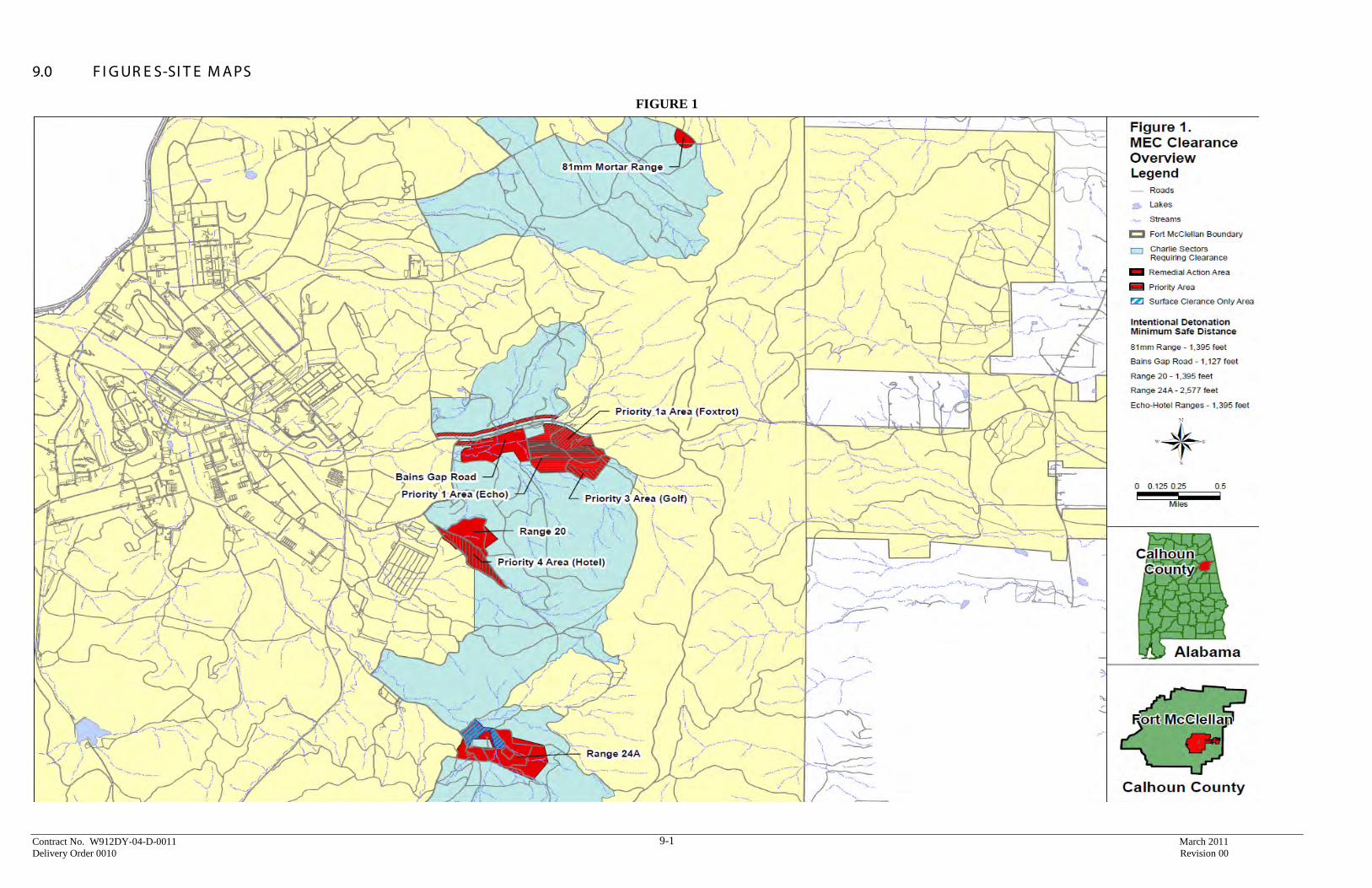
Contract No. W912DY-04-D-0011 March 2011 Delivery Order 0010 Revision 00
9-1
9.0 F I G UR E S-SI T E M APS
FIGURE 1

Contract No. W912DY-04-D-0011 March 2011 Delivery Order 0010 Revision 00
9-2
FIGURE 2
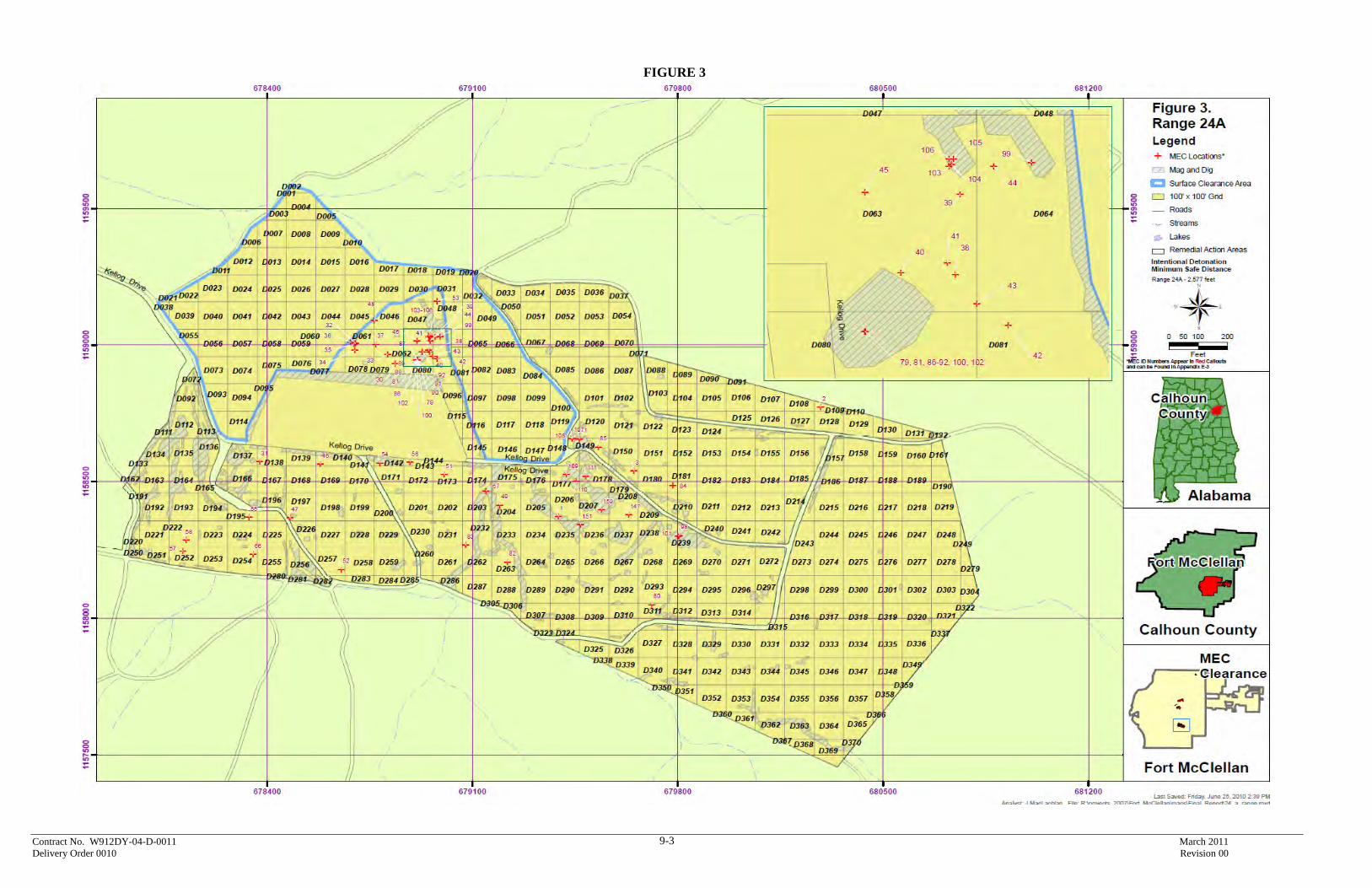
Contract No. W912DY-04-D-0011 March 2011 Delivery Order 0010 Revision 00
9-3
FIGURE 3

Contract No. W912DY-04-D-0011 March 2011 Delivery Order 0010 Revision 00
9-4
FIGURE 4

Contract No. W912DY-04-D-0011 March 2011 Delivery Order 0010 Revision 00
9-5
FIGURE 5
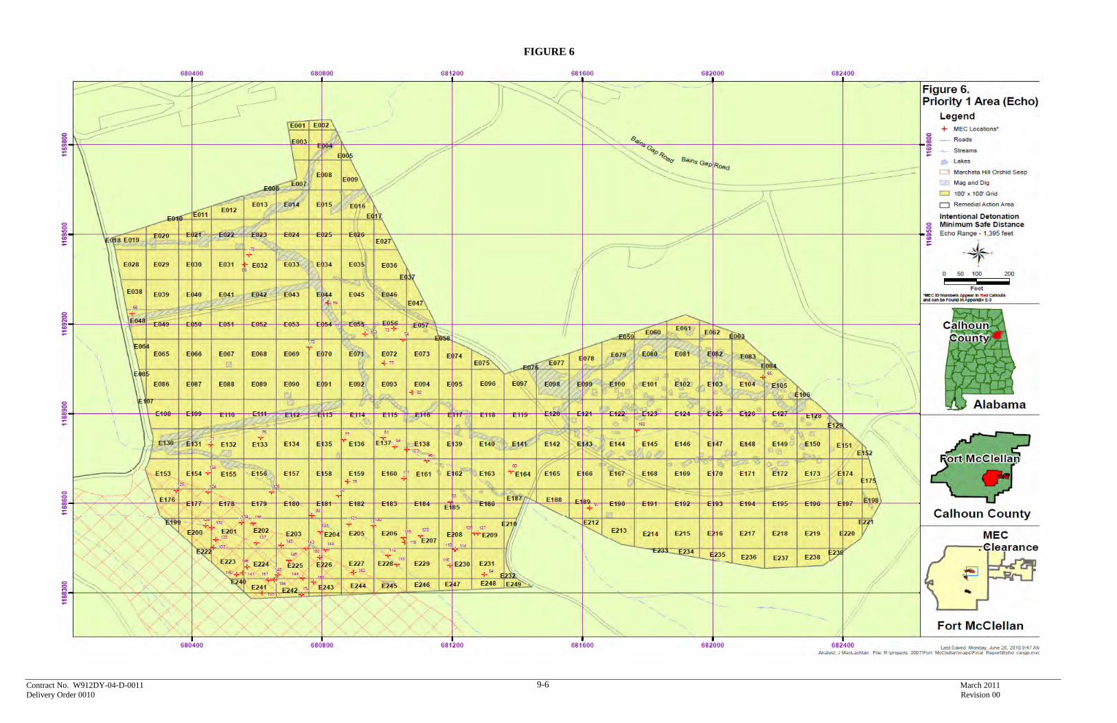
Contract No. W912DY-04-D-0011 March 2011 Delivery Order 0010 Revision 00
9-6
FIGURE 6

Contract No. W912DY-04-D-0011 March 2011 Delivery Order 0010 Revision 00
9-7
FIGURE 7

Contract No. W912DY-04-D-0011 March 2011 Delivery Order 0010 Revision 00
9-8
FIGURE 8
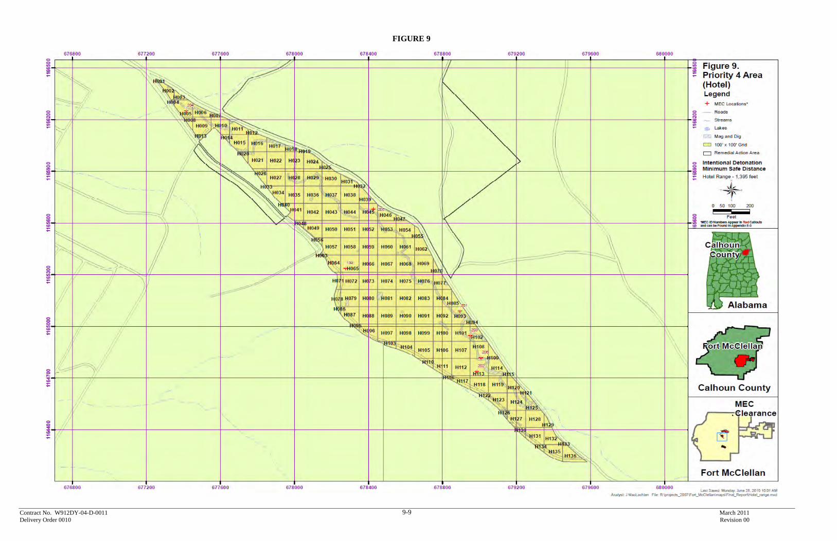
Contract No. W912DY-04-D-0011 March 2011 Delivery Order 0010 Revision 00
9-9
FIGURE 9

Contract No. W912DY-04-D-0011 March 2011 Delivery Order 0010 Revision 00
10-1
10.0 R E SPONSE S T O C OM M E NT S Responses to FWS Comments
Draft Site Specific Final Report Remedial Action at Selected Sites within Charlie Area
Fort McClellan, Alabama
Comments from Stephen A. Miller, dated October 27, 2010. Section 2.2.1. The text states that a portion of the ground system for the Explosive Magazine is located outside of the fenced compound. The U.S. Fish and Wildlife Service's Mountain Longleaf National Wildlife Refuge (Refuge) approved the Explosive Magazine's current location on the Refuge to facilitate clean up of MEC in 2009. The Service was not aware that a portion of the magazine's ground system was installed outside the fenced compound. The Service recommends that the Army delineate this area in order to avoid potential damage to the grounding system during future restoration work by the Service in that area. No change in this document is required to address this comment. RESPONSE: The Army will delineate the area. Section 2.2.4.1. The text states that all vegetation less than 4 inches in diameter was removed from the project areas. The text should be changed to note that as few longleaf pine trees as possible, including those less than 4-inches, were disturbed while preparing the site for the removal action. This proposed change is consistent with the Final Work Plan Remedial Action Charlie Area Section 11.1.1 (Appendix A-2) and is what occurred on the site. The Service requests that any future clearance actions continue to include brush clearance that minimizes disturbance to longleaf pine trees within the project area. RESPONSE: The text in Section 2.2.4.1 has been changed as requested. Section 2.4.1 states that 30 storm drainage pipe/culvert structures located within the Charlie Area were removed and the area determined to be cleared of ordnance items. These culverts were left in place during earlier remedial actions associated with Roads and Firebreaks clearance (see Service comments on Final Site Specific Final Report FWS Land Transfer Area dated October 1, 2008). It was determined that clearance beneath these culverts was necessary for long term maintenance of Refuge roads. With this clearance complete, only the culverts under paved roads (Bain's Gap Road, Baby Bain's Gap Road and Kellog Avenue) have not been cleared and will require construction support during future maintenance actions associated with these culverts. No clearance has been done under any of the paved portions of Kellog Avenue while all anomalies, except for culverts, under Bain's Gap Road and Baby Bain's Gap Road (both of which are paved) have been cleared. No change in this document is required to address this comment. RESPONSE: Culverts requiring construction support during future maintenance actions will be identified in the Charlie Area EE/CA.
Contract No. W912DY-04-D-0011 March 2011 Delivery Order 0010 Revision 00
10-2
Section 2.6.1 identifies the 199 pop-up target emplacements that were removed through this remedial action. Based upon earlier documentation, at least 254 target emplacements were identified either within the remedial action area or in adjacent areas that were previously cleared under earlier actions. The Service requests a determination from the Army on the remaining 55 emplacements as to whether these will be removed by the Army during future actions or will be the responsibility of the Service to remove. A determination should also be made regarding whether the area beneath these emplacements is, in fact, cleared to depth as originally reported. To avoid this or a similar issue in the future, the Service requests that all cultural debris associated with Army training be removed as clearance actions are completed. No change in this document is required to address this comment. RESPONSE: The area was cleared to depth as originally reported. However, the Army agreed to remove target emplacements on future removals, and the 55 emplacements is included in the current contract actions for the next removal action. Cultural debris that is an impediment to remediation activities or is a safety issue will be removed. Section 2.9.4.1 identifies 206 munitions and explosives of concern (MEC) that were removed under this action. Appendix A-4 identifies the locations of MEC items. At least three areas containing MEC appear to be located within 200 feet of areas previously identified as No Further Action (NFA). Specifically, Appendix A-4 Figure 4 identifies MEC items appearing to be less than 200 feet from an NFA within Grid A002, Figure 7 within Grid F071, and Figure 8 within Grid G022. During the dispute resolution process, associated with the original Draft Final EECA for the Charlie Area, it was agreed that any MEC items discovered adjacent to a NFA boundary would require clearance be completed at least 200 additional feet beyond this item to insure that characterization of the area is correct. These three areas in addition to Road Segments 98 and 99 identified within the Site Specific Final Report FWS Land Transfer Area may require adjustments of the NFA. No change in this document is required to address this comment although this comment does need to be addressed within any future version of the EECA. REPSONSE: Boundary adjustments for items found in referenced grids and road segments will be addressed in the Charlie Area EE/CA.

Contract No. W912DY-04-D-0011 March 2011 Delivery Order 0010 Revision 00
10-3
Responses to ADEM Comments Draft Site Specific Final Report Revision 01,
Remedial Action at Selected Sites within Charlie Area Fort McClellan, Alabama
Comments from Stephen A. Cobb, dated March 8, 2011.
1. Page 2-5, Section 2.7.2.2: As a guideline for selecting targets for excavation Line 39 states, "The top coil greater than or equal to the bottom coil 660 us time gate." Please explain how the top coil reading can be greater than the bottom coil, which is closer to the anomaly.
RESPONSE: The top coil response is typically higher than or equal to the lower coil response for buried items because the gain settings are different for the two coils. When the top coil is greater than or equal to the bottom coil, this typically indicates the item is buried, while if the top coil is less than the bottom coil, this often indicates that the item is on the surface. This criterion was initially put in so that scrap items much smaller than a 37mm that were located on the surface did not necessarily have to be included on the dig list even if they were a little higher in amplitude than 4 mV. It was determined during data interpretation that attempting to use this criterion in practice was too difficult and was therefore not actually used. This criteria statement will be removed from the report.
2. Page 2-11, Table 2-5: Please explain why no project total percentage is given for surface clearance only for Range 24A.
RESPONSE: Table 2-5 will be updated to include 5.24% for surface clearance only for Range 24A.
3. Page 5-3, Section 5.3.4.1: Line 24 states that "it was anticipated that a minimum of six seed items....would be emplaced in grids designated as Analog "EM & Dig" grids." Then Line 29 states that UXOQC (unexploded ordnance quality control specialist) emplaced 224 seed items in these small "EM & Dig" areas. Please explain how the number of seed items increased from an estimated 6 to 224 even though the area requiring "EM & Dig" was small.
RESPONSE: The statement will be revised to state that 6 blind seed items would be placed in “each” EM & Dig grid.
Contract No. W912DY-04-D-0011 March 2011 Delivery Order 0010 Revision 00
10-4
4. Page 5-5, Section 5.3.6.1: This section references a series of standardized
quality checks that were performed daily by the geophysics team. However, documentation of these checks does not appear to be included in the geophysics notes in Appendix B-4. Please clarify if there is any documentation that these daily tests were performed.
RESPONSE: This information was captured digitally and all geophysical QC results are documented in the MS Access Project Database folder located on the attached DVD (#2). The file name is DID_Tables_data.mdb
5. Page 5-5, Section 5.4.2: This section states that the QC (quality control) inspection rate was increased when the anomaly selection criteria was raised from 5-mV to 7-mV. However, documentation of this change and why it was implemented cannot be found in the report. Please clarify if a field change request was submitted and approved for this change in accordance with Sections 2.6.6 and 10.12 of the work plan.
RESPONSE: The referenced section does not actually state that the anomaly selection criteria was raised from 5-mV to 7-mV. The anomaly selection criteria was never changed and remained the same throughout the project. The section actually states that the field action level (real-time response during QC hole check) was changed from 5 mV to 7 mV. The field action level was an initial number used as a guideline for QC to help determine if an item that met the failure criteria might remain in an excavated hole. Based on intrusive results of hole checks, the action level was modified as discussed in the report. This field action level modification did not change the work plan and therefore an FCR was not required
6. Appendix B-2: Please include an explanation for the linear feature in Echo Area seen on the map on Page 6 of the Echo Area geophysical maps and other similar features on other maps.
RESPONSE: The grid maps will be revised to include notations describing the linear feature in Echo Area.
7. Appendix B-4: It appears that sometimes the geophysical sensor equipment serial numbers and a sketch of the survey area are not provided in the Geophysical Field Notes. These inconsistencies should have been flagged during QC reviews of documentation. Please explain why this important information is not complete and why this deficiency was not identified during the QC and QA (quality assurance) reviews.
RESPONSE: All of the log books for the four geophysical mapping teams list the equipment used and the corresponding serial number for that piece of equipment. Each team labeled their equipment with their corresponding team number, as not to confuse it with the other team’s equipment. The teams used the same equipment throughout the project. In order for a new piece of equipment to be used, the team would have to map the GPO and await approval before continuing geophysical mapping. Since the serial numbers of the equipment were recorded in
Contract No. W912DY-04-D-0011 March 2011 Delivery Order 0010 Revision 00
10-5
the Logbooks, QC did not feel it was necessary to enter the equipment serial number on the Field Data Sheets. After reviewing the field data sheets it was found that 5 of the sheets do not contain sketches, this occurred on April 15, 2009 by Geo 2. They had 5 files that day and did not draw any sketches for the grids. This was an error on the first day of mapping for this team. When they turned in the sheets to the Geophysical Field Lead at the end of the day, he communicated to the Geo 2 Team Lead that sketches should be included. The field sketches for the remainder of the project were completed. QC did not feel that this was a significant non-conformance as it was addressed immediately.
8. Appendix C: The information contained in this appendix is incomplete and inconsistent. Many fields are not completed and frequently the columns for "Channel 2 Final" and "Intrusive mV Response" are not filled in. Please clarify why these were not completed and what the implications of not having recorded this data are for project quality.
RESPONSE: It appears to Tetra Tech that the information in Appendix C is complete. There are reasons the fields listed as being incomplete do not have entries. All targets that have the letters “MD” in the Target ID field are mag & dig targets and do not have an EM61 response associated with them (CH2 final). All targets that have a letter designation at the end of the Target ID field (e.g., C0006-008A) are secondary items found at a target location. No entries are required in the coordinates or CH2 final response fields. These fields would be the same as the initial Target ID (e.g., C0006-008).
The Intrusive mV Response field has values only for items that were checked with an EM61 after intrusive investigation. Not all holes were checked with an EM61 following intrusive as this was not required. EM & Dig holes (MD in Target ID) were not checked with an EM61 either.