Rd2 White Paper
12
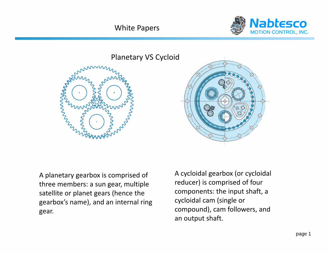
MOTION CONTROL, INC. MOTION CONTROL, INC. Planetary VS Cycloid White Papers page 1 A planetary gearbox is comprised of three members: a sun gear, multiple satellite or planet gears (hence the gearbox’s name), and an internal ring gear. A cycloidal gearbox (or cycloidal reducer) is comprised of four components: the input shaft, a cycloidal cam (single or compound), cam followers, and an output shaft.
description
GEarbox calc
Transcript of Rd2 White Paper
MOTION CONTROL, INC.MOTION CONTROL, INC.
Planetary VS Cycloid
White Papers
page 1
A planetary gearbox is comprised of
three members: a sun gear, multiple
satellite or planet gears (hence the
gearbox’s name), and an internal ring
gear.
A cycloidal gearbox (or cycloidal
reducer) is comprised of four
components: the input shaft, a
cycloidal cam (single or
compound), cam followers, and
an output shaft.

MOTION CONTROL, INC.MOTION CONTROL, INC.
Planetary gearboxes
White Papers
page 2
A planetary gearbox is comprised of three members: a SUN gear, multiple satellite or PLANET gears, and an
internal ring gear. The input shaft attaches to the sun gear, which transmits rotational motion to the planet gears,
which in turn rotate the internal RING gear, which is part of the gearbox housing. Planet gears rotate on rigid
shafts attached to a plate called a planet carrier; this rotation of the planet carrier is what causes the output shaft
to rotate. As with all mechanical speed reduction, this gives the output shaft a lower rotational speed and higher
torque than the input shaft. Planetary gearboxes may also be single- or double-reduction, with reduction ratios
ranging from 3:1 to over 100:1. Additional stages can be added for even higher reduction, or to change output
shaft orientation (i.e. via bevel gearing, miter gearing, etc.).

MOTION CONTROL, INC.MOTION CONTROL, INC.
A cycloidal gearbox (or cycloidal reducer) is
comprised of four components: the input shaft, a
cycloidal cam (single or compound), cam followers,
and an output shaft. The input shaft attaches to a
drive member that induces an eccentric rotation of
Cycloidal gearboxes
White Papers
page 3
drive member that induces an eccentric rotation of
the cycloidal cam; in compound reducers, the first
cycloidal cam engages a second cycloidal cam
(double reduction), which may then engage a third
cycloidal cam (triple reduction). The cam followers
act as gear teeth, and will exceed the number of
cam lobes. Cycloidal gearboxes offer ratios from as
low as 10:1 to over 300:1 without stacking stages in
the manner of a planetary gearbox, and thus
cycloidal gearboxes may have a more compact
footprint. A typical cycloidal gear is seen here:

MOTION CONTROL, INC.MOTION CONTROL, INC.
The drive or servomotor is
connected to the spur gear stage
of the gearbox via a pinion.
White Papers
page 4
The first reduction gears are connected to crankshafts which
drive the cams using needle bearings. These cams rotate
inside the case which is lined with pins.

MOTION CONTROL, INC.MOTION CONTROL, INC.
Planetary VS Cycloid
Planetary Gears may run at higher
speeds.
Cycloidal Gears are very good for extremely heavy
loads.
Planetary Gears will work with very low
Ratio’s.
Cycloidal Gears work at higher ratio’s allowing them to be driven with less
White Papers
page 5
Cycloidal Gears work at higher ratio’s allowing them to be driven with less
power.
Planetary Gears are good if positioning accuracy and lost motion are not a
concern.
Cycloidal Gears are best in applications for high positioning accuracy and a
minimum lost motion is required.
Planetary Gears are ok if regular “monthly maintenance” is acceptable for the
application.
Cycloidal Gears are best if little maintenance and long gear life are
required.

MOTION CONTROL, INC.MOTION CONTROL, INC.
Things to consider when choosing a Gearbox.
After many years developing Cycloidal Gears our engineers have created some basic
questions to help you in the beginning steps of selecting a gearbox for your
application.
What environmental conditions will gear box need to endure? (Operating
temperature, dust, moisture exposure, ect.)
White Papers
page 6
What physical size envelope does your gear box need? (any shape or space
requirements)
Maintenance and lubrication access? (After the application is assembled how will
you maintain the gear box?)

MOTION CONTROL, INC.MOTION CONTROL, INC.
How much torque do you require to do the work required by the application?
(Weight it needs to move.)
What if any, speed requirement does the application require? (How
fast you need the gear box to go.)
Angle of the gearbox mounting? (Horizontally ,vertically or angled.)
White Papers
page 7
Angle of the gearbox mounting? (Horizontally ,vertically or angled.)
Moment rigidity? (Weight deflection of the gear box shaft due to the fixture
and work load.)
Torsional rigidity? (Shaft deflection, stopping and starting the application
load.)

MOTION CONTROL, INC.MOTION CONTROL, INC.
Momentary Maximum allowable torque? (Worst case
E-stop condition with a load.)
What kind of duty cycle will the Gear box have? (Hours
of operation and number of days per week.)
White Papers
page 8
of operation and number of days per week.)
MOTION CONTROL, INC.MOTION CONTROL, INC.
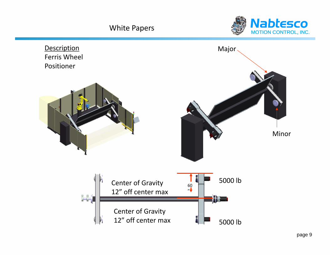
Description
Ferris Wheel
Positioner
Major
White Papers
page 9
Minor
5000 lb
5000 lbCenter of Gravity
12” off center max60
”
Center of Gravity
12” off center max

MOTION CONTROL, INC.MOTION CONTROL, INC.White Papers
page 10

MOTION CONTROL, INC.MOTION CONTROL, INC.White Papers
page 11

MOTION CONTROL, INC.MOTION CONTROL, INC.White Papers
page 12