
Radial flow advancement in multi-layered preform for resin ...Radial flow advancement in...
8
Transcript of Radial flow advancement in multi-layered preform for resin ...Radial flow advancement in...
Korea-Australia Rheology Journal December 2006 Vol. 18, No. 4 217
Korea-Australia Rheology JournalVol. 18, No. 4, December 2006 pp. 217-224
Radial flow advancement in multi-layered preform for resin transfer molding
K. S. Shin, Y. S. Song and J. R. Youn*
School of Materials Science and Engineering, Seoul National University,Shillim-Dong, Gwanak-Gu, Seoul 151-744, Korea
(Received July 6, 2006; final revision received September 12, 2006)
Abstract
Rapid flow advancement without void formation is essential in the liquid composite molding (LCM) suchas resin transfer molding (RTM) and vacuum assisted resin transfer molding (VARTM). A highly permeablelayer in multi-layered preform has an important role in improvement of the flow advancement. In this study,a multi-layered preform which consists of three layers is employed. Radial flow experiment is carried outfor the multi-layered preform. A new analytic model for advancement of flow front is proposed and effec-tive permeability is defined. The effective permeability for the multi-layered preform is obtained ana-lytically and compared with experimental results. Compaction test is performed to determine the exact fibervolume fraction of each layer in the multi-layered preform. Transverse permeability employed in modelingis measured experimentally unlike the previous studies. Accurate prediction of flow advancement is of greatuse for saving the processing time and enhancing product properties of the final part.
Keywords : preform, resin transfer molding, permeability, woven fabric, random mat
1. Introduction
Recently, resin transfer molding (RTM) has been popular
in the aircraft components, automobile parts, and military
industries because it promises cost savings and perfor-
mance improvement than traditional hand lay-up method
(Advani et al., 1994). In the resin transfer molding, a two-
part mold is made out of metallic materials. Dry fiber pre-
form is packed into a mold cavity which is made in the
shape of desired part. The mold is closed and the resin is
injected into the mold where it infiltrates the fiber preform.
Then, the cure cycle begins and the mold and resin are
heated for the polymerization reaction. Finally, the mold is
opened and the composite part is removed. The greatest
benefit of RTM different from other polymer composite
manufacturing techniques is the separation of molding pro-
cess from the design of fiber architecture. Other benefits
are production of very large and complex shape, short
cycle time, low labor requirement, low equipment costs,
and controllable fiber volume fraction. There are a number
of variables to control, e.g., resin viscosity, injection pres-
sure, temperature of resin and mold, degree of cure, loca-
tion of gates and vent holes, and permeability of the
preform. In the design and tooling of the mold, it is impor-
tant to predict how the mold is filled during the injection
process. Permeability is one of the most important param-
eters to understand impregnation of the preform.
Experimental measurement of the permeability has been
conducted in many studies (Adams and Rebenfeld, 1987;
Chae, 2004; Cho et al., 2003; Endruweit et al., 2002; Lai
et al., 1997; Parnas and Salem, 1993; Weitzenböck et al.,
1999). In general, two experimental measurement meth-
ods, i.e. unidirectional flow and radial flow experiments,
have been utilized to measure the in-plane permeability of
fiber preforms, such as woven fabric, non-woven fabric,
and multi-layered preform. In the RTM process, impreg-
nation of the resin into the preform can be described by the
Darcy’s law which is empirically derived as the following.
(1)
where u is the velocity vector and K is the permeability
tensor. It is well-known that the Darcy’s law provides a
very good approximation of flow behavior on a macro
scale (Advani et al., 1994). Many researchers have inves-
tigated the permeability of multi-layered preform from uni-
directional flow experiment (Bruschke et al., 1992; Calado
and Advani, 1996; Diallo et al., 1998; Jinlian et al., 2004;
Luce et al., 1995; Mogavero and Advani, 1997; Seong et
al., 2002). They usually used a weighted average perme-
ability which could not consider transverse permeability.
However, contribution of the transverse flow cannot be
neglected in the multi-layered preform. Especially, when
the preform is relatively thick and the difference between
in-plane permeabilities of adjacent layers is large, the trans-
uK
η----– ∇P=
*Corresponding author: [email protected]© 2006 by The Korean Society of Rheology
K. S. Shin, Y. S. Song and J. R. Youn
218 Korea-Australia Rheology Journal
verse flow contribution is more significant. Adams and
Rebenfeld (1991) suggested a permeability model for
radial flow. However, they considered only the preforms
having the same porosity and used semi-permeable wall
model. Chen et al. (2004) proposed an effective perme-
ability, but could not predict exact advancement of the flow
front through analytic conditions.
In multi-layered preforms, a high permeability layer
plays a crucial role in the flow advancement and its per-
meability value greatly influences the overall in-plane per-
meability. Because there are limits on production of large
parts and increase of fiber volume fraction in the con-
ventional RTM, the RTM is being replaced with vacuum
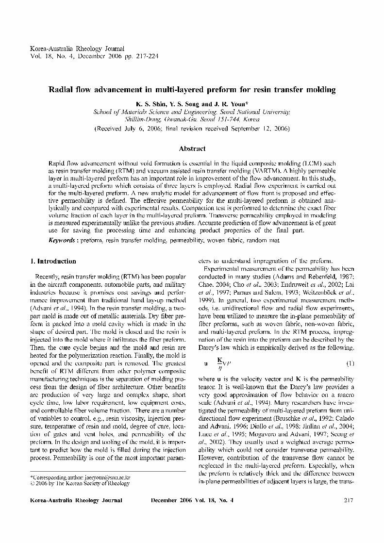
assisted resin transfer molding (VARTM). In the VARTM,
a resin distribution medium (RDM) is placed on the pre-
form to help the resin flow as shown in Fig. 1. The RDM
makes the resin impregnation into the preform easier with-
out voids because the moving distance of resin becomes
very short (Mathur et al., 2001). Therefore, highly per-
meable layer like the RDM is necessary to save cost and
time in the composite manufacturing process. To predict
the overall permeability for multi-layered preform stack
containing the layer with high in-plane permeability, con-
tribution of the transverse flow on the entire permeability
and compaction behavior of the multi-layered preform
should be understood (Batch et al., 2002; Chen and Chou,
1999; Chen et al., 2001; Luo and Verpoest, 1999; Parseval
et al., 1997).
In this study, advancement of flow front in multi-layered
preform is predicted by using a proposed analytic model.
In contrast to the previous studies, exact fiber volume frac-
tion and height of each layer are acquired from the com-
paction test for the multi-layered preform and transverse
permeability is measured experimentally. In order to verify
the proposed analytic model, analytic results are compared
with experimental ones. Effective permeability is also pro-
posed and compared with average permeability.
2. Theory
2.1. Permeability measurementIn-plane permeability measurement is largely divided
into two methods: one is unidirectional flow experiment
and the other is radial one. The unidirectional flow method
can measure the individual components of permeability
tensor, while the radial flow method can determine not
only the principal direction but also the principal values of
permeability tensor in the plane direction at the same time.
In addition, the radial flow experiment avoids edge effects
which are usually accompanied in the unidirectional flow
experiment.
Two dimensional radial flow in porous media is
described by the Darcy’s law as follows.
(2)
where vr is the volume averaged fluid velocity, µ is the
dynamic viscosity of the fluid, and ∂P/∂r is the pressure
gradient. A mass balance in the region filled with fluid is
used to obtain the radial pressure gradient. The mass bal-
ance for the case of an isotropic porous media in which the
flow front has a circular shape is expressed as below.
(3)
where r1 and r2 are the two radii within the resin filled
region and vr1 and vr2 are the fluid velocities in radial direc-
tion at r1 and r2. There are several assumptions. Firstly, all
experiments are performed under constant inlet pressure.
Secondly, microscopic flow, gravitational, and surface ten-
sion effects are ignored. Lastly, it is assumed that the wet-
ted domain is fully saturated with the test fluid.
The Darcy’s law and the mass balance equation are com-
bined by using the boundary conditions of P=Pi at the
inlet and P=0 at the flow front to obtain the following
equation.
(4)
where Rf is the radius of the flow front and ro is the inlet
radius. The pressure gradient varies with the reciprocal of
radial position. The differential equation generated by the
kinematic condition is given by
(5)
where ε is the porosity of the preform, and ∆P is the pres-
sure difference between Pf at the flow front and Pi at the
inlet.
By applying the initial condition, Rf = r0 at t=0, the
dimensionless solution is derived as below.
(6)
(7)
(8)
where ρf is the dimensionless radius and Φ is the dimen-
vr
K
µ----–∂P
∂r------=
2πr1vr1 2πr2vr2=
∂P
∂r------
Pi
rln Rf ro⁄( )------------------------–=
dRf
dt-------- K∆P
εµ------------
1
Rf ln Rf ro⁄( )----------------------------=
G ρf( ) ρf2
2lnρf 1–( ) 1+( ) 4⁄ Φ= =
ρf Rf r0⁄=
Φ Kt∆P εµr02⁄=
Fig. 1. Schematic diagram of VARTM.
Radial flow advancement in multi-layered preform for resin transfer molding
Korea-Australia Rheology Journal December 2006 Vol. 18, No. 4 219
sionless time. The permeability can be obtained (Adams et
al., 1988; Cho et al., 2003) from the experimental data of
Φ vs. ρf by the following relation.
(9)
where m is the slope of the line obtained by the least square
fitting of Φ vs. ρf.
2.2. Analytic model2.2.1. Flow advancement
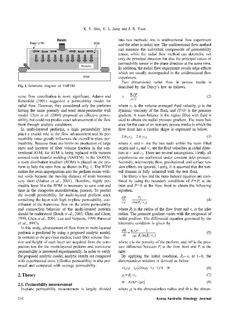
The multi-layered preforms selected in this study are
composed of three layers and have sandwich structure as
shown in Fig. 2. Adams and Rebenfeld (1991) and Brus-
chke et al. (1992) proposed analytical models for flow
front advancement in the preform with two layers but
didn’t consider exact transverse permeability and fiber vol-
ume fraction of each layer in the multi-layered preform. On
the contrary, the actual transverse permeability and fiber
volume fraction obtained experimentally are taken into
account in the present analytic model.
The pressure profile for radial flow is different from that
of unidirectional flow. That is, the latter is assumed to be
linear in the resin filled region and the former isn’t. By
solving the Darcy’s law and the continuity equation for
radial flow with proper boundary conditions, the pressure
gradient with respect to radial flow direction is given by
the Eq. (4).
Volumetric flow rate of each layer is obtained using the
Darcy’s law as follows.
(10)
(11)
(12)
where Q1, and Q2 are the volumetric flow rate of each layer
in radial flow direction, Qt is the volumetric flow rate in the
transverse flow direction, h1 and h2 are the thickness of
each layer, Ur1 and Ur2 are the volume averaged fluid veloc-
ity of each layer, and R1 and R2 are the radius of the flow
front at each layer.
Most studies on the multi-layered preform have been
based on the assumption that the net flow rates between
adjacent layers are equal as shown below.
(13)
Therefore, R1, R2, and R3 are calculated as follows by
assuming that the volume averaged fluid velocity of each
layer has reached the steady state.
(14)
(15)
By substituting Eqs. (10) to (12) to Eqs. (14) and (15), the
governing equations can be obtained as the following.
(16)
(17)
where Kr1 is the permeability of the first layer in the
radial direction and Kt is the permeability in the trans-
verse direction. There are a number of parameters in
order to solve these equations. From the experimental
measurements, porosities, permeabilities, and height of
each layer are determined. Flow advancement with respect
to time can be acquired by solving Eqs. (16) and (17)
numerically.
2.2.2. Effective permeability
In this study, a new overall effective permeability is pro-
posed in the radial flow direction. In Cartesian coordinate
system, a second order permeability tensor is defined by
the following the Dacry’s law.
Kmεµr0
2
∆P---------------=
Q1 Q3 2πR1h1Ur1 2πR1h1
Kr1
µ-------
∂P
∂r------
R1
–⎝ ⎠⎛ ⎞ 2πh1Kr1
µ-------------------
Pi–
lnr0R1
-----⎝ ⎠⎛ ⎞
---------------= = = =
Q2 2πR2h2Ur2 2πR2h2
Kr2
µ-------
∂P
∂r------
R2
–⎝ ⎠⎛ ⎞ 2πh2Kr2
µ-------------------
Pi–
lnr0R2
-----⎝ ⎠⎛ ⎞
---------------= = =
Qt
2πKtPi R1 R2+( ) R2 R1–( )µ h1 h2+( )
----------------------------------------------------------
lnR1 R2+
2R2
----------------⎝ ⎠⎛ ⎞
lnr0R2
-----⎝ ⎠⎛ ⎞
--------------------------=
Q1 Qt+ Q2 2Qt– Q3 Qt+= =
R1 R3
t
ε1
----Q1 Qt+
2πR1h1
-----------------⋅= =
R2
t
ε2
----Q2 2Qt–
2πR2h2
-------------------⋅=
R1 R3
t Pi⋅µε1R1h1
-------------------h1Kr1
lnr0R1
-----⎝ ⎠⎛ ⎞
---------------Kt R1 R2+( ) R1 R2–( )
h1 h2+( )----------------------------------------------
lnR1 R2+
2R2
----------------⎝ ⎠⎛ ⎞
lnr0R2
-----⎝ ⎠⎛ ⎞
--------------------------–
⎩ ⎭⎪ ⎪⎪ ⎪⎨ ⎬⎪ ⎪⎪ ⎪⎧ ⎫
= =
R2
t Pi⋅µε2R2h2
-------------------1
lnr0R2
-----⎝ ⎠⎛ ⎞
--------------- h2Kr2
2Kt R1 R2+( ) R1 R2–( )h1 h2+( )
-------------------------------------------------lnR1 R2+
2R2
----------------⎝ ⎠⎛ ⎞+
⎩ ⎭⎨ ⎬⎧ ⎫
=
Fig. 2. Configuration of flow advancement through multi-layered
preform.
K. S. Shin, Y. S. Song and J. R. Youn
220 Korea-Australia Rheology Journal
(18)
For an orthotropic preform, the permeability tensor can be
transformed into a symmetric matrix with zero off-diag-
onal terms.
(19)
The overall flow rate is expressed in the radial direction as
follows.
(20)
(21)
where is the effective permeability and is the effec-
tive radius of the flow front. According to the mass bal-
ance, the total flow rate is also given as below.
(22)
By substituting Eqs. (10), (11), and (20) into Eq. (22), the
effective permeability can be obtained as the following.
(23)
3. Experiment
3.1. Materials and experimental setupThe preforms selected in this study were plain woven
fabrics, glass random mats, and circular braided hybrid
preforms. The plain woven fabrics included glass fiber
woven fabrics, aramid fiber woven fabrics, hybrid fiber
woven fabrics and carbon fiber woven fabrics. The fluid
used in this study was the silicone oil (dimethyl siloxane
polymer, DC 200F/100CS) supplied by Dow Corning. The
silicone oil showed Newtonian behavior and the viscosity
of the silicone oil was 9.7×10⁻² Pa⋅s.
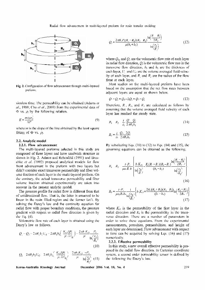
The mold designed for the two-dimensional radial flow
experiment is schematically illustrated in Fig. 3. The radial
flow was generated by injecting the fluid through a central
gate into a 500×500 mm cavity between two parallel plates
containing the reinforcing fiber structure. The upper trans-
parent plate is made out of acrylic resin (PMMA), which
enabled us to observe the mold-filling pattern visually. A
digital camcorder was used to record the flow pattern.
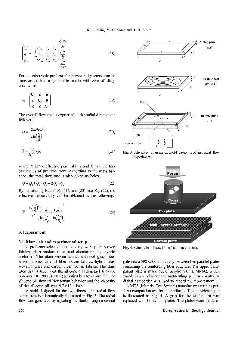
A MTS (Material Test System) machine was used to per-
form compaction test for the preforms. The empirical setup
is illustrated in Fig. 4. A grip for the tensile test was
replaced with horizontal plates. The plates were made of
ux
uy
uz⎝ ⎠⎜ ⎟⎜ ⎟⎜ ⎟⎛ ⎞
1
η---–
Kxx
Kyx
Kzx
Kxy
Kyy
Kzy
Kxz
Kyz
Kzz⎝ ⎠⎜ ⎟⎜ ⎟⎛ ⎞
∂P
∂x------
∂P
∂y------
∂P
∂z------⎝ ⎠⎜ ⎟⎜ ⎟⎜ ⎟⎜ ⎟⎜ ⎟⎜ ⎟⎛ ⎞
=
K
Kxx
0
0
0
Kyy
0
0
0
Kzz⎝ ⎠⎜ ⎟⎜ ⎟⎛ ⎞
=
Q2πHPi K–
µlnr0
R----⎝ ⎠⎛ ⎞
-----------------------=
R1
H---- rihi
i 1=
n
∑=
K R
Q Q1 Q2 Q3+ + 2Q1 Q2+= =
K
lnr0
R----⎝ ⎠⎛ ⎞
H--------------
2h1Kr1
lnr0R1
-----⎝ ⎠⎛ ⎞
----------------h2Kr2
lnr0R2
-----⎝ ⎠⎛ ⎞
---------------+
⎝ ⎠⎜ ⎟⎜ ⎟⎜ ⎟⎛ ⎞
=
Fig. 3. Schematic diagram of mold cavity used in radial flow
experiment.
Fig. 4. Schematic illustration of compaction test.
Radial flow advancement in multi-layered preform for resin transfer molding
Korea-Australia Rheology Journal December 2006 Vol. 18, No. 4 221
stainless steel with a rectangular shape. Upper mold was
connected to a load cell of the MTS machine and lower one
was placed on the flat plate. Preform layers of 80×80 mm2
were stacked uniformly and were located between flat steel
plates. The load range used was 0-20 kN and compression
rate was 1 mm/min. Thickness of the fabric stack was mea-
sured with respect to the imposed load.
3.2. Permeability measurementPermeabilities of glass fiber random mats, glass fiber
plain woven fabrics, aramid fiber plain woven fabrics, and
hybrid plain woven fabrics were measured by the unsat-
urated radial flow experiment. The resin was injected to the
mold under constant low pressure. Pressure of liquid resin
was measured by pressure transducers at the inlet. The per-
meability was measured at different fiber volume fractions
by compressing the fiber preform to different heights. The
multi-layered preform shown in Fig. 2 was utilized. The
preform consisted of three layers. Top and bottom layers
were the same preforms and the middle layer had the high-
est permeability among three layers. The preform had a
sandwich structure. The top and bottom layers were aramid
fiber plain woven fabrics and the middle layer was glass
fiber plain woven fabric.
In order to obtain transverse permeability, transverse
flow experiment in the gapwise direction was performed.
The steady state flow rate was measured by collecting the
outflow from the mold during measured time. The pressure
gradient was obtained by pressure transducers after the
fiber preforms were completely impregnated. The trans-
verse permeability of the fiber preform was calculated
through the Darcy’s law.
4. Results and discussion
4.1. In-plane permeability Four different homogeneous preforms and one multi-lay-
ered preform are used for radial flow experiment. The mid-
dle layer can increase the total permeability and the flow
rate significantly as a highly permeable preform. From the
experiment for homogeneous preforms, a glass fiber plain
woven fabric is selected as the highly permeable layer.
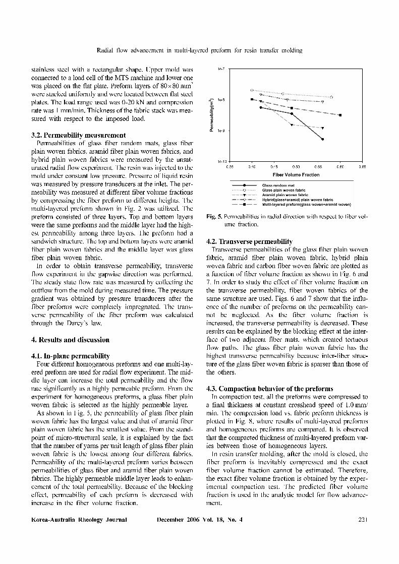
As shown in Fig. 5, the permeability of glass fiber plain
woven fabric has the largest value and that of aramid fiber
plain woven fabric has the smallest value. From the stand-
point of micro-structural scale, it is explained by the fact
that the number of yarns per unit length of glass fiber plain
woven fabric is the lowest among four different fabrics.
Permeability of the multi-layered preform varies between
permeabilities of glass fiber and aramid fiber plain woven
fabrics. The highly permeable middle layer leads to enhan-
cement of the total permeability. Because of the blocking
effect, permeability of each preform is decreased with
increase in the fiber volume fraction.
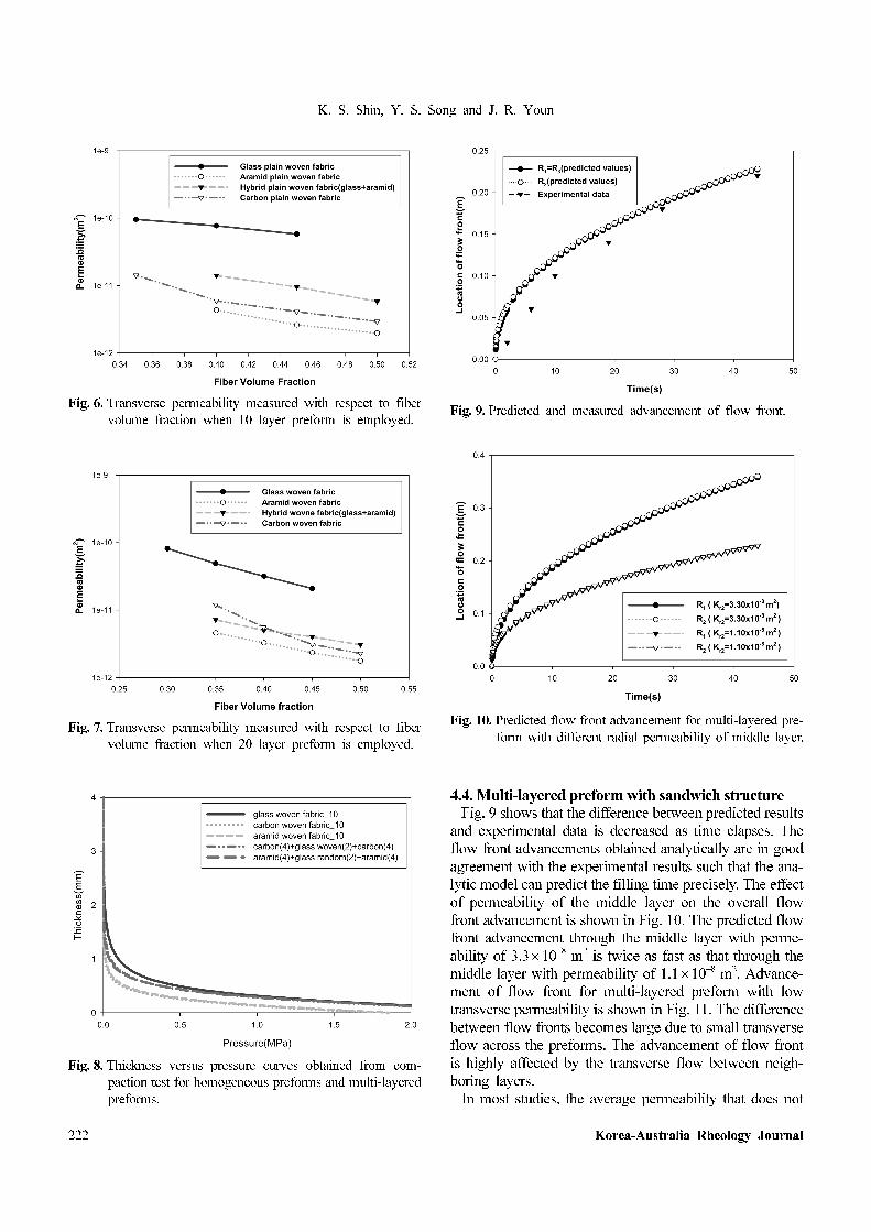
4.2. Transverse permeabilityTransverse permeabilities of the glass fiber plain woven
fabric, aramid fiber plain woven fabric, hybrid plain
woven fabric and carbon fiber woven fabric are plotted as
a function of fiber volume fraction as shown in Fig. 6 and
7. In order to study the effect of fiber volume fraction on
the transverse permeability, fiber woven fabrics of the
same structure are used. Figs. 6 and 7 show that the influ-
ence of the number of preforms on the permeability can-
not be neglected. As the fiber volume fraction is
increased, the transverse permeability is decreased. These
results can be explained by the blocking effect at the inter-
face of two adjacent fiber mats, which created tortuous
flow paths. The glass fiber plain woven fabric has the
highest transverse permeability because inter-fiber struc-
ture of the glass fiber woven fabric is sparser than those of
the others.
4.3. Compaction behavior of the preformsIn compaction test, all the preforms were compressed to
a final thickness at constant crosshead speed of 1.0 mm/
min. The compression load vs. fabric preform thickness is
plotted in Fig. 8, where results of multi-layered preforms
and homogeneous preforms are compared. It is observed
that the compacted thickness of multi-layered preform var-
ies between those of homogeneous layers.
In resin transfer molding, after the mold is closed, the
fiber preform is inevitably compressed and the exact
fiber volume fraction cannot be estimated. Therefore,
the exact fiber volume fraction is obtained by the exper-
imental compaction test. The predicted fiber volume
fraction is used in the analytic model for flow advance-
ment.
Fig. 5. Permeabilities in radial direction with respect to fiber vol-
ume fraction.
K. S. Shin, Y. S. Song and J. R. Youn
222 Korea-Australia Rheology Journal
4.4. Multi-layered preform with sandwich structureFig. 9 shows that the difference between predicted results
and experimental data is decreased as time elapses. The
flow front advancements obtained analytically are in good
agreement with the experimental results such that the ana-
lytic model can predict the filling time precisely. The effect
of permeability of the middle layer on the overall flow
front advancement is shown in Fig. 10. The predicted flow
front advancement through the middle layer with perme-
ability of 3.3×10⁻⁸ m2 is twice as fast as that through the
middle layer with permeability of 1.1×10⁻⁸ m2. Advance-
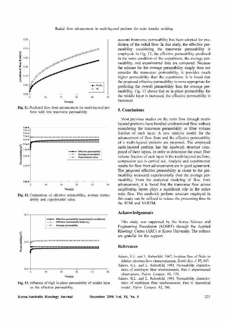
ment of flow front for multi-layered preform with low
transverse permeability is shown in Fig. 11. The difference
between flow fronts becomes large due to small transverse
flow across the preforms. The advancement of flow front
is highly affected by the transverse flow between neigh-
boring layers.
In most studies, the average permeability that does not
Fig. 7. Transverse permeability measured with respect to fiber
volume fraction when 20 layer preform is employed.
Fig. 6. Transverse permeability measured with respect to fiber
volume fraction when 10 layer preform is employed.
Fig. 8. Thickness versus pressure curves obtained from com-
paction test for homogeneous preforms and multi-layered
preforms.
Fig. 9. Predicted and measured advancement of flow front.
Fig. 10. Predicted flow front advancement for multi-layered pre-
form with different radial permeability of middle layer.
Radial flow advancement in multi-layered preform for resin transfer molding
Korea-Australia Rheology Journal December 2006 Vol. 18, No. 4 223
account transverse permeability has been adopted for pre-
diction of the radial flow. In this study, the effective per-
meability considering the transverse permeability is
employed. In Fig. 12, the effective permeability predicted
in the same condition of the experiment, the average per-
meability, and experimental data are compared. Because
the scheme for the average permeability simply does not
consider the transverse permeability, it provides much
higher permeability than the experiment. It is found that
the proposed effective permeability is more appropriate for
predicting the overall permeability than the average per-
meability. Fig. 13 shows that as in-plane permeability for
the middle layer is increased, the effective permeability is
increased.
5. Conclusions
Most previous studies on the resin flow through multi-
layered preforms have handled unidirectional flow without
considering the transverse permeability or fiber volume
fraction of each layer. A new analytic model for the
advancement of flow front and the effective permeability
of a multi-layered preform are proposed. The employed
multi-layered preform has the sandwich structure com-
posed of three layers. In order to determine the exact fiber
volume fraction of each layer in the multi-layered preform,
compaction test is carried out. Analytic and experimental
results for flow front advancements are in good agreement.
The proposed effective permeability is closer to the per-
meability measured experimentally than the average per-
meability. From the analytical modeling of flow front
advancement, it is found that the transverse flow across
neighboring layers plays a significant role in the entire
resin flow. The sandwich preform structure employed in
this study can be utilized to reduce the processing time in
the RTM and VARTM.
Acknowledgements
This study was supported by the Korea Science and
Engineering Foundation (KOSEF) through the Applied
Rheology Center (ARC) at Korea University. The authors
are grateful for the support.
References
Adams, K.L. and L. Rebenfeld, 1987, In-plane flow of fluids in
fabrics: structure/flow characterization, Textile Res. J. 57, 647.
Adams, K.L. and L. Rebenfeld, 1991, Permeability character-
istics of multilayer fiber reinforcements. Part I: experimental
observations, Polym. Compos. 12, 179.
Adams, K.L. and L. Rebenfeld, 1991, Permeability character-
istics of multilayer fiber reinforcements. Part II: theoretical
model, Polym. Compos. 12, 186.
Fig. 11. Predicted flow front advancement for multi-layered pre-
form with low transverse permeability.
Fig. 12. Comparison of effective permeability, average perme-
ability and experimental value.
Fig. 13. Influence of high in-plane permeability of middle layer
on the effective permeability.
K. S. Shin, Y. S. Song and J. R. Youn
224 Korea-Australia Rheology Journal
Adams, K. L., W. B. Russel and L. Rebenfeld, 1988, Radial pen-
etration of viscous liquid into a planar anisotropic porous
medium, Int. J. Multiphase Flow 14, 203.
Advani, S.G., M.V. Bruschke and R.S. Parnas, 1994, Flow and
Rheology in Polymer Composites Manufacturing, Elsevier,
Amsterdam.
Batch, G.L., S. Cumiskey and C.W. Macosko, 2002, Compaction
of fiber reinforcements, Polym. Compos. 23, 307.
Bruschke, M.V., T.L. Luce and S.G. Advani, 1992, Effective in-
planer permeability of multi-layered RTM performs, Proceed-
ings of the 7th Technical Conference of the American Society
for Composites, University Park, PA, U.S.A., 103.
Calado, V.M.A. and S.G. Advani, 1996, Effective average per-
meability of multi-layer preforms in resin transfer molding,
Compos. Sci. Technol. 56, 519.
Chae, H.S., 2004, Out-of-plane permeability measurement of
braided preform in resin transfer molding, Master Thesis,
Seoul National University, Seoul.
Chen, B. and T.W. Chou, 1999, Compaction of woven-fabric pre-
forms in liquid composite molding process: single-layer defor-
mation, Compos. Sci. Technol. 59, 1519.
Chen, B., A.H.D. Cheng and T.W. Chou, 2001, A nonlinear com-
paction model for fibrous performs, Compos. Part A 32, 701.
Chen, Z., L. Ye and H. Liu, 2004, Effective permeabilities of
multilayer fabric preforms in liquid composite moulding, Com-
pos. Struct. 66, 351.
Cho, Y.K., Y.S. Song, T.J. Kang, K. Chung and J.R. Youn, 2003,
Permeability Measurement of a circular braided preform for
resin transfer molding, Fibers and Polymers 4, 135.
Diallo, M.L., R. Gauvin and F. Trochu, 1998, Experimental anal-
ysis and simulation of flow through multi-layer fiber rein-
forcements in liquid composite molding, Polym. Compos. 19,
246.
Endruweit, A., T. Luthy and P. Ermanni, 2002, Investigation of
the influence of textile compression of the out-of-plane per-
meability of a bidirectional glass fiber fabric, Polym. Compos.
23, 538.
Jinlian, H., L. Yi and S. Xueming, 2004, Study on void formation
in multi-layer woven fabrics, Compos. Part A 35, 595.
Lai, Y.H., B. Khomami and J.L. Kardos, 1997, Accurate per-
meability characterization of preforms used in polymer matrix
composite fabrication process, Polym. Compos. 18, 368
Luce, T.L., S.G. Advani, J.G. Howard and R.S. Parnas, 1995, Per-
meability characterization. Part 2: flow behavior in multiple-
layer performs, Polym. Compos. 16, 446.
Luo, Y. and I. Verpoest, 1999, Compressibility and relaxation of
a new sandwich textile preform for liquid composite molding,
Polym. Compos. 20, 179.
Mathur, R., D. Heider, C. Hoffmann, J.W. Gillespie, S.G. Advani
and B.K. Fink, 2001, Flow front measurements and model val-
idation in the vacuum assisted resin transfer molding process,
Polym. Compos. 22, 477.
Mogavero J. and S.G. Advani, 1997, Experimental investigation
of flow through multi-layered performs, Polym. Compos. 18,
649.
Parnas, R.S. and A.J. Salem, 1993, A comparison of the uni-
directional and radial in-plane flow of fluids through woven
composite reinforcements, Polym. Compos. 14, 383.
Parseval, Y.D., K.M. Pillai and S.G. Advani, 1997, A simple
model for the variation of permeability due to partial saturation
in dual scale porous media, Transport in Porous Media 27, 243.
Seong, D.G., K. Chung, T.J. Kang and J.R. Youn, 2002, A study
on resin flow through a multi-layered preform in resin transfer
molding, Polym. Polym. Compos. 10, 493.
Weitzenböck, J.R., R.A. Shenoi and P.A. Wilson, 1999, Radial
flow permeability measurement. Part A : theory, Compos. Part
A 30, 781.
Weitzenböck, J.R., R.A. Shenoi and P.A. Wilson, 1999, Radial
flow permeability measurement. Part B: application, Compos.
Part A 30, 797.