search.jsp?R=19770009071 2018-05 …. J. O’Brlen Prepared bv MCDONNELL AIRCRA- COMPANY BOX 516,...
61
https://ntrs.nasa.gov/search.jsp?R=19770009071 2018-06-27T01:48:01+00:00Z
Transcript of search.jsp?R=19770009071 2018-05 …. J. O’Brlen Prepared bv MCDONNELL AIRCRA- COMPANY BOX 516,...

https://ntrs.nasa.gov/search.jsp?R=19770009071 2018-06-27T01:48:01+00:00Z
Copy number NASA CR-151932
Reportnumber w)C A4551 LIFT/CRUISE FAN V/STOL TECHNOLOGY AIRCRAFT
DESIGN DEFINITION STUDY VOLUME 11
PROPULSION TRANSMISSION SYSTEK DESIGN
Revision date Revision letter
Issuedate 18 November 1976 contract number NAS2-9245
Wm. J. O’Brlen Prepared bv
MCDONNELL AIRCRA- COMPANY
BOX 516, Soin* Louis, Missouri 63166 - Tal. 1334J232-0232
MCOONNELL
CORpdRAIlOU
W C A4551 VOLUME I1
INTRODUCTION Aim SUNWARY
This report presents results of Task 111 of a study by McDonnell Aircraft Company (MCAIR) for NASA Ames Research Center and the U.S. Navy to conceptually design two types of Liftkruise Fan Technology Aircraft. turbotip fans pneumatically interconnected to three gas generators and the other aircraft used variable pitch fans mechanically interconnected to three turboshaft engines. The objective of Task I11 was to analyze and design the
One aircraft used
components of each propulsion transmission system to the depth necessary to determine areas of risk, development methods, performance, weights and costs. The types of materials and manufacturing processes were identified to show that the designs followed a low cost approach. ing hoods, which are applicable to either aircraft configuration, were also evaluated to assure a low cost/low risk approach.
The lift/cruise fan thrust vector-
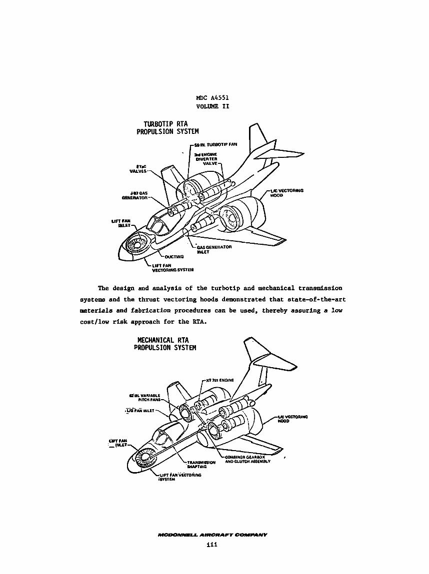
The turbotip propulsion system consists of three General Electric (G.E.) LCF459 turbotip fans powered by three G.E. YJ97 gas generators through the Energy Transfer and Control (ETaC) system. bellows and control valves. would be a MCAIR developed light weight, composite design; however, stainless steel was selected for the RTA to assure a low cost/law risk approach. stainless steel ducting is approximately 500 lb heavier than a composite con- struction but the excess thrust margin available in the turbotip RTA allows
The ETaC system consists of ducting, The ducting system for an operational aircraft
The
this approach to be used. reduce cost.
already demonstrated by the XV-5 aircraft thereby minimizing risk. tion of the ETaC system components indicated that all could be fabricated
from existing materials using standard fabrication proceduree.
A single duct was installed for the lift fan to The operating temperature, 1260°F, is nearly the same as that
An evalua-
The mechanical propulsion system consists of three Hamilton Standard variable pitch fans powered by three Detroit Diesel Allison (DDA) XT701 turboshaft engines through a mechanical transmission system. includes shafting, supports, combiner gearbox, lift fan clutch and an over- running clutch for the third engine. cal transmission system was subcontracted to DDA to utilize their expertise as a leading designer and fabricator of power transmission components. MCAIR guidelines, which included the use of standard materials and state-of-the- art sizing criteria, DDA arrived at a low risk design for the mechanical trans- mission system.
This system
The design and analysis of the mechani-
Based on
MDC A4551 VOLUME 11
TURBOTIP RTA PROPULSION SYSTEM n
WIN TURBOIlP FAN
U C VECTORING
The design and analysis of the turbotlp and mechanical transmission systems and the thrust vectoring hoods demonstrated that state-of-the-art materials and fabrication procedures can be used, thereby assuring a low cost/law r isk approach for the RTA.
MECHANICAL RTA PROPULSION SYSTEM
VC VECIORINO
.
MDC A4551 VOLUME I1
TABLE OF CC'YTENTS . Sect ion
1 .
2 .
3 .
Title pa_ge INTRODUCTION AND SUMMARY . . . . . . . . . . . . . . . . . . ii
LIsT OF FIGURES . . . . . . . . . . . . . . . . . . . . . . V
TURBOTIP TRANSMISSION SYSTEM . . . . . . . . . . . . . . . . 1 1.1 General Description . . . . . . . . . . . . . . . . . . 1 1.2 System Selection . . . . . . . . . . . . . . . . . . . 3 1.3 Ducting System . . . . . . . . . . . . . . . . . . . 4
1.3.1 Ducting . . . . . . . . . . . . . . . . . . . . 4 1.3.2 Elbows . . . . . . . . . . . . . . . . . . . . . 4 1.3.3 Transition Sections . . . . . . . . . . . . . . 4 1.3.4 Supports . . . . . . . . . . . . . . . . . . . . 4 1.3.5 Thermal Insulation . . . . . . . . . . . . . . . 6 1.3.6 Bellows . . . . . . . . . . . . . . . . . . . . 6
1.4 Valves . . . . . . . . . . . . . . . . . . . . . . . . 9 . . . . . . . . . . . . . 1.4.1 Engine Isolation Valve r 1.4.2 Engine ETaC Modulation Valve . . . . . . . . . . 9 1.4.3 Engine ETaC and Shutoff Valve . . . . . . . . . 9 1.4.4 Interconnect Isolation Valves . . . . . . . . . 12 1.4.5 Diverter Valve . . . . . . . . . . . . . . . . . 12
1.6 Component Materials Selection . . . . . . . . . . . . . 14 1.5 Engine Diffuser and Alignment Bearings Section . . . . 12
LIFT/CRUISE FAN THRUST VECTORING DEVICES . . . . . . . . . . 17 2.1 General Description . . . . . . . . . . . . . . . . . . 17 2.2 Thrust Vectoring Hoods . . . . . . . . . . . . . . . . 17 2.3 Yaw Doors . . . . . . . . . . . . . . . . . . . . . . . 19 MECHANICAL TRANSMISSION SYSTEM . . . . . . 20 3.1 General Description . . . . . . . . . . . . . . . . . . 20 3.2 Transmission System Design . . . . . . . . . . . . . . 21
APPENDIX A SHAFT AND TRANSMISSION DESIGN STUDY BY DETROIT DIESEL ALLISON . . . . . . . . . . . . . . . . . . . . . . . . . . A-1
LIST OF PAGES Title
ii through v 1 through 21
A-l through A-31
MDC A4551 VOLUME I1
LIST OF FIGURES
Number
1 2 3 4 5 6 7 8 9 10 11 12 13 14 15 16 17
. Title . Gas RTA ETaC System . . . . . . . . . . . . . . . . . . . . . Ducting Configuration . . . . . . . . . . . . . . . . . . . . M260-RT.4-1 Gas Distribution System 'Y' Duct Assembly . . . . Main Anchor Support . . . . . . . . . . . . . . . . . . . . . Swinging Support . Linkage . . . . . . . . . . . . . . . . . Swinging Support . Hinge . . . . . . . . . . . . . . . . . . Sliding Support . Bolt Type . . . . . . . . . . . . . . . . . Directional Anchor . Rolling Support . . . . . . . . . . . . M260-RTA-1 Engine/Fan Gas Distribution Angulation Bellows . . Engine/Fan Coupling Arrangement . . . . . . . . . . . . . . . M260-RTA-1 ETaC modulation & Gas Distribution Valve . . . . . ETaC + Shut Off Gas Distribution Valve . . . . . . . . . . . Engine Diffuser and Alignment Bearing Section . . . . . . . . I'D" Vented Nozzle Wall Temperature Measurements . . . . . . . M260-RTA-1 Lift/Cruise Fan Hood Design . . . . . . . . . . . M260-RTA-1 Lift/Cruise Fan Yaw Door Design . . . . . . . . . Model 260-RTA-2 Propulsion System . . . . . . . . . . . . . .
Page
2 5 5 7 7 7 8 8 10 10 11 11 13 18 18 19 20
MDC A4551 VOLUME I1
1. TURBOTIP TRANSMISSION SYSTEM
1.1 GENERAL DESCRIPTION
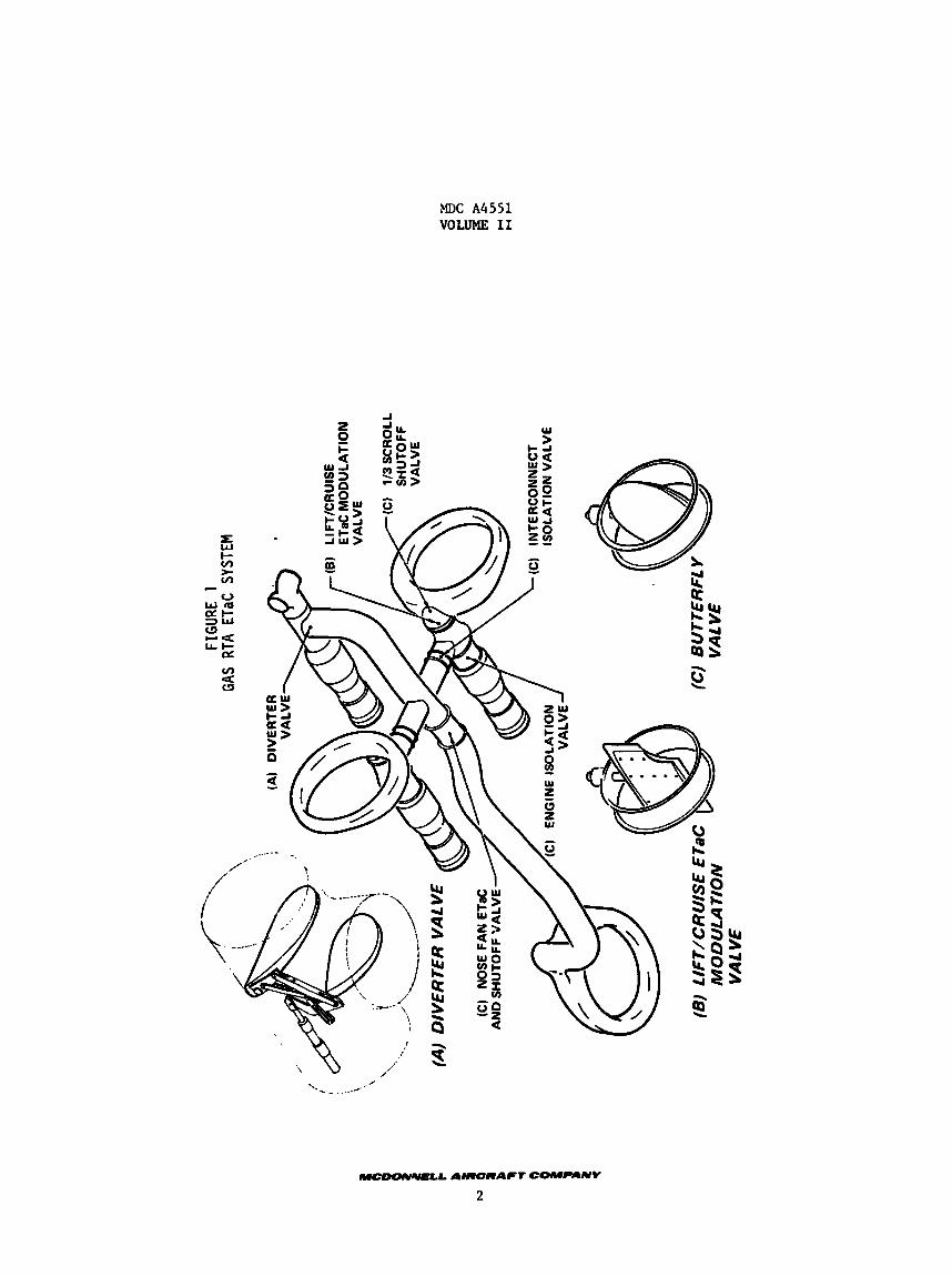
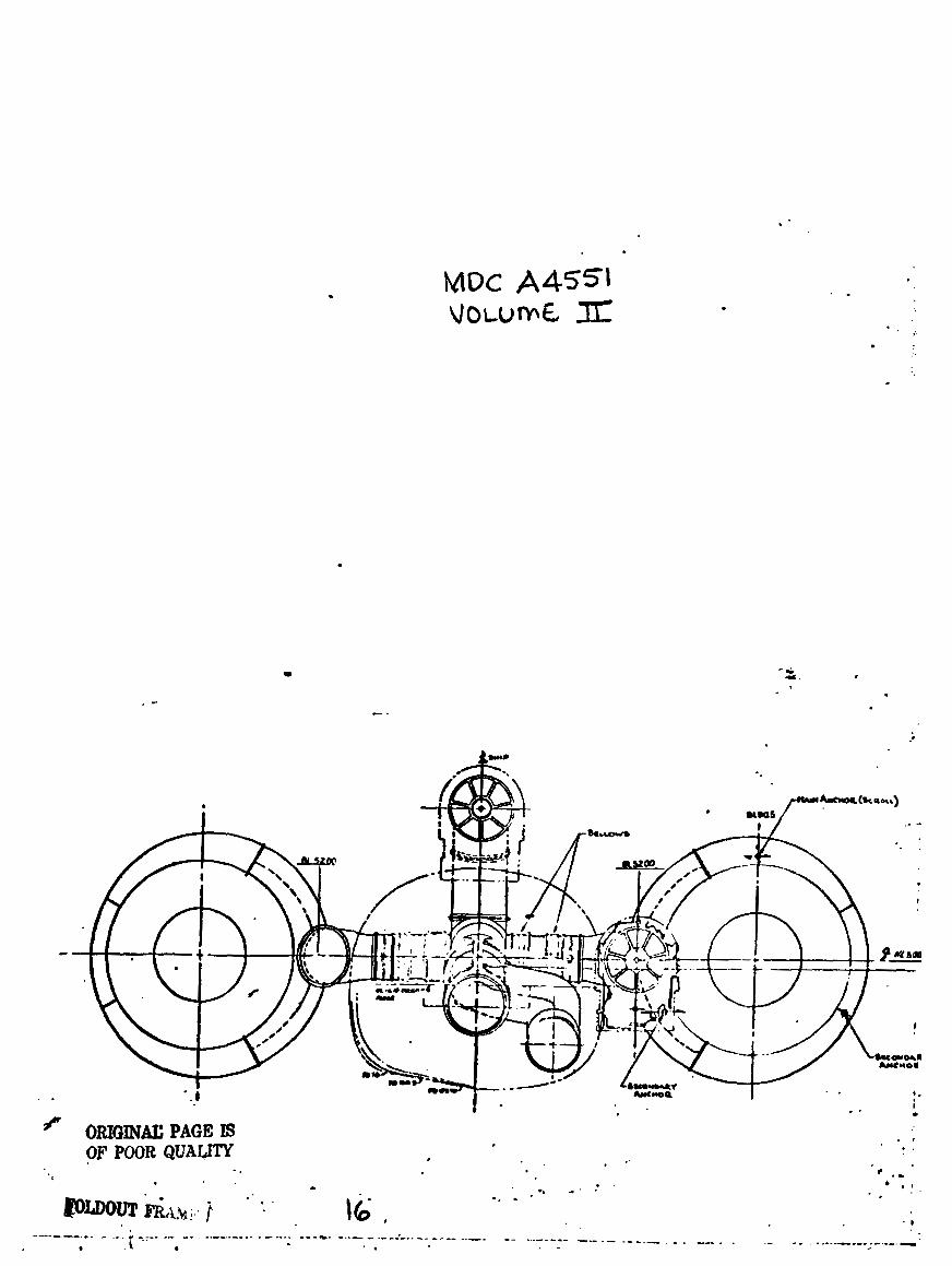
The Energy Transfer and Control (ETaC) system is used to distribute and control the exhaust gas from the General Electric (G.E.) iJ97 gas generators to the three G.E. LCF459 turbotip fans. consists of: ducting, valves for control and/or shutoff, and a system of bellows
joints for thermal expansion compensation. high energy gas from the engines to perform the following functions:
This integrated duct system, Figure 1,
The ETaC system distributes the
(a) (b)
Distribution of the gas tc the turbotip fans
Provides the proper distribution for control during takeoff and conversion
Provides for gas transfer in the event of an engine failure Isolates and bypasses the failed portion of the system from the active portion Provides the proper distribution of gas for cruise and high speed flight Allows the third engine to be isolated from the main system after "V" takeoff or to be brought back on line for a "V" landing.
To assure a low cost/low risk approach, two major guidelincs were
(c) (d)
(e)
(f)
established: (1) use stainless steel ducting, and (2) use only one duct for the lift fan. of approximately 500 lb as compared to the MCAIR developed composite ducting but provides for a low risk development program using state-of-the-art fabrica- tion procedures.
employed for the RTA. all fans to be identical with the exception of the entry segment.
The use of stainless steel ducting results in a weight penalty
The single duct to the lift fan is a low cost approach This single duct approach also allowed the scrolls of
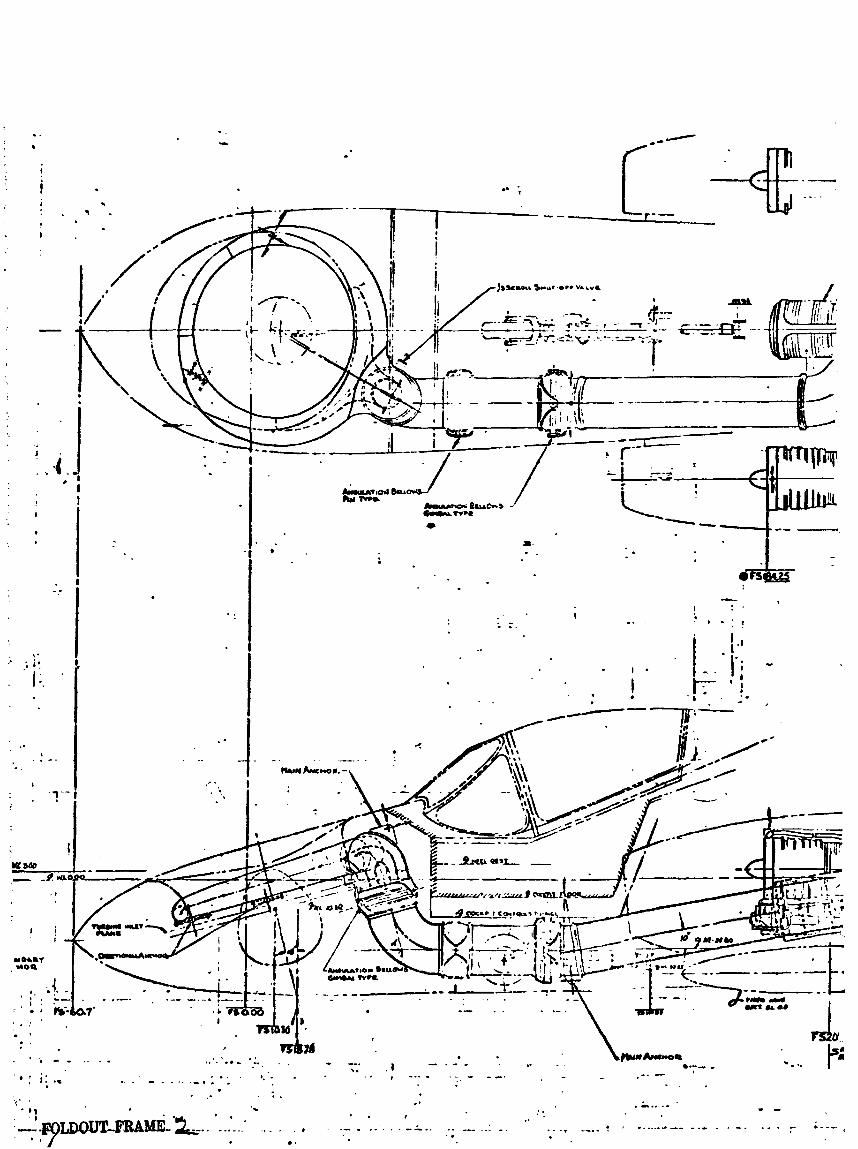
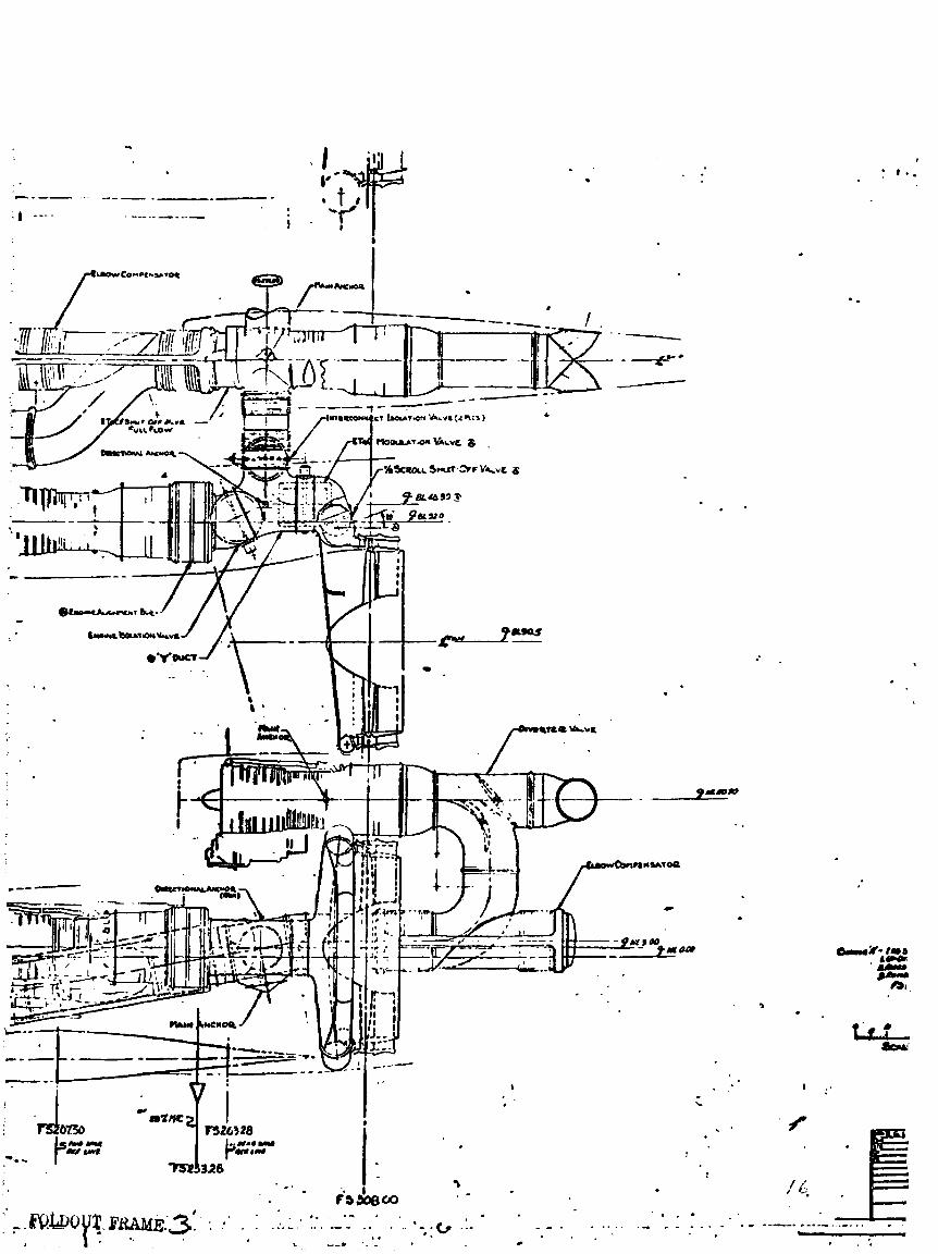
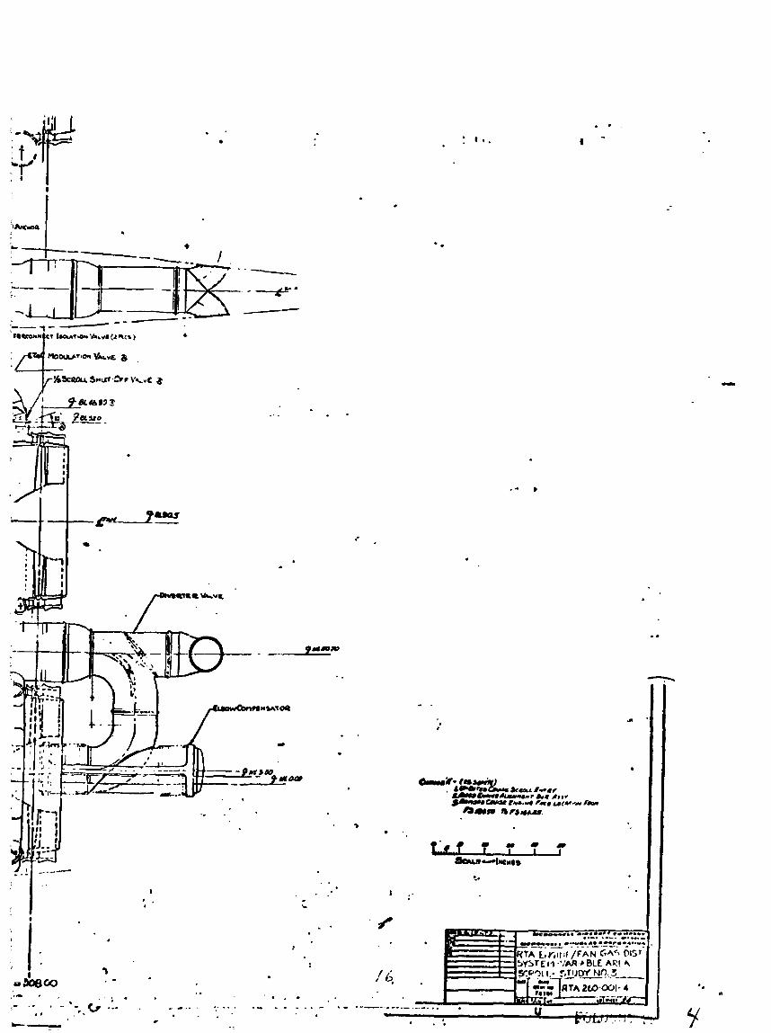
The overall ETaC system design was coordinated with various speciality manufacturers to assure simplicity of fabricacion. These manufacturers in-
cluded Metal Bellows Co., Stainless Steel Products, and kiLowhead Products. A layout of the ETaC system, Drawing RTA 260-001-4, wa8 p'sparsd to assure
that the system components interfaced properly with each o t h r and with the fan scrolls. Each of the major com-
ponents were designed and evaluated and are discussed in the following
paragraphs.
This design i - s coordinated with G.E.
M-LL A#UCRAPT COMPANY
1
MDC A4551 VOLUME I1
M C O O U W E U . AIRCRAFT COMPLINV
2
MDC A4551 VOLUME I1
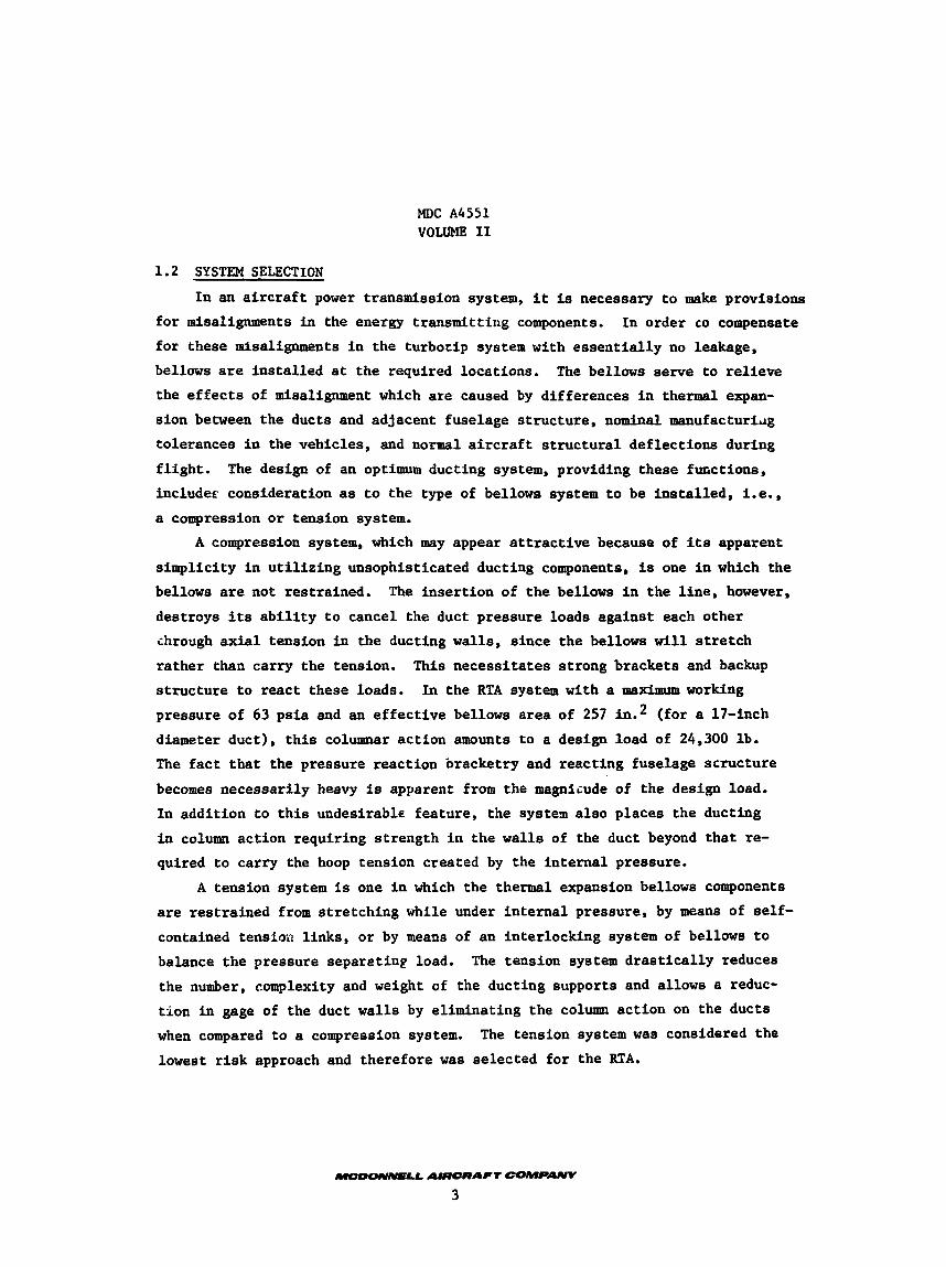
1.2 SYSTEM SELECTION
In an aircraft power transmission system, it is necessary to make provisions for misalignments in the energy transmitting components. for these misalignments in the turbotip system with essentially no leakage,
bellows are installed at the required locations. the effects of misalignment which are caused by differences in thermal expan- sion between the ducts and adjacent fuselage structure, nominal manufacturidg
tolerances in the vehicles, and normal aircraft structural deflections during flight. includer consideration as to the type of bellows system to be installed, i.e., a compression or tension system.
In order co compensate
The bellows serve to relieve
The design of an optimum ducting system, providing these futctions,
A compression system, which may appear attractive because of its apparent
simplicity in utilizing unsophisticated ducting components, is one in which the bellows are not restrained. The insertion of the bellows in the line, however,
destroys its ability to cancel the duct pressure loads against each other chrough axial tension in the ducting walls, since the bellows will stretch rather than carry the tension. structure to react these loads. pressure of 63 psia and an effective bellows area of 257 diameter duct), this columnar action amounts to a design load of 24,300 lb. The fact that the pressure reaction bracketry and reacting fuselage structure
becomes necessarily heavy is apparent from the magniiude of the design load. In addition to this undesirable feature, the system also places the ducting
in column action requiring strength in the walls of the duct beyond that re- quired to carry the hoop tension created by the internal pressure.
This necessitates strong brackets and backup In the RTA system with a maximum working
(for a 17-inch
A tension system I s one in which the thermal expansion bellows components are restrained from stretching while under internal pressure, by means of self- contained tensiou links, or by means of an interlocking system of bellows to balance the pressure separeting load. The tension system drastically reduces
the number, complexity and weight of the ducting supports and allows a reduc- tion in gage of the duct walls by eliminating the column action on the ducts when compared to a compression system.
lowest risk approach and therefore was selected for the RTA.
The tension system was considered the
MDC A4551 VOLUME 11
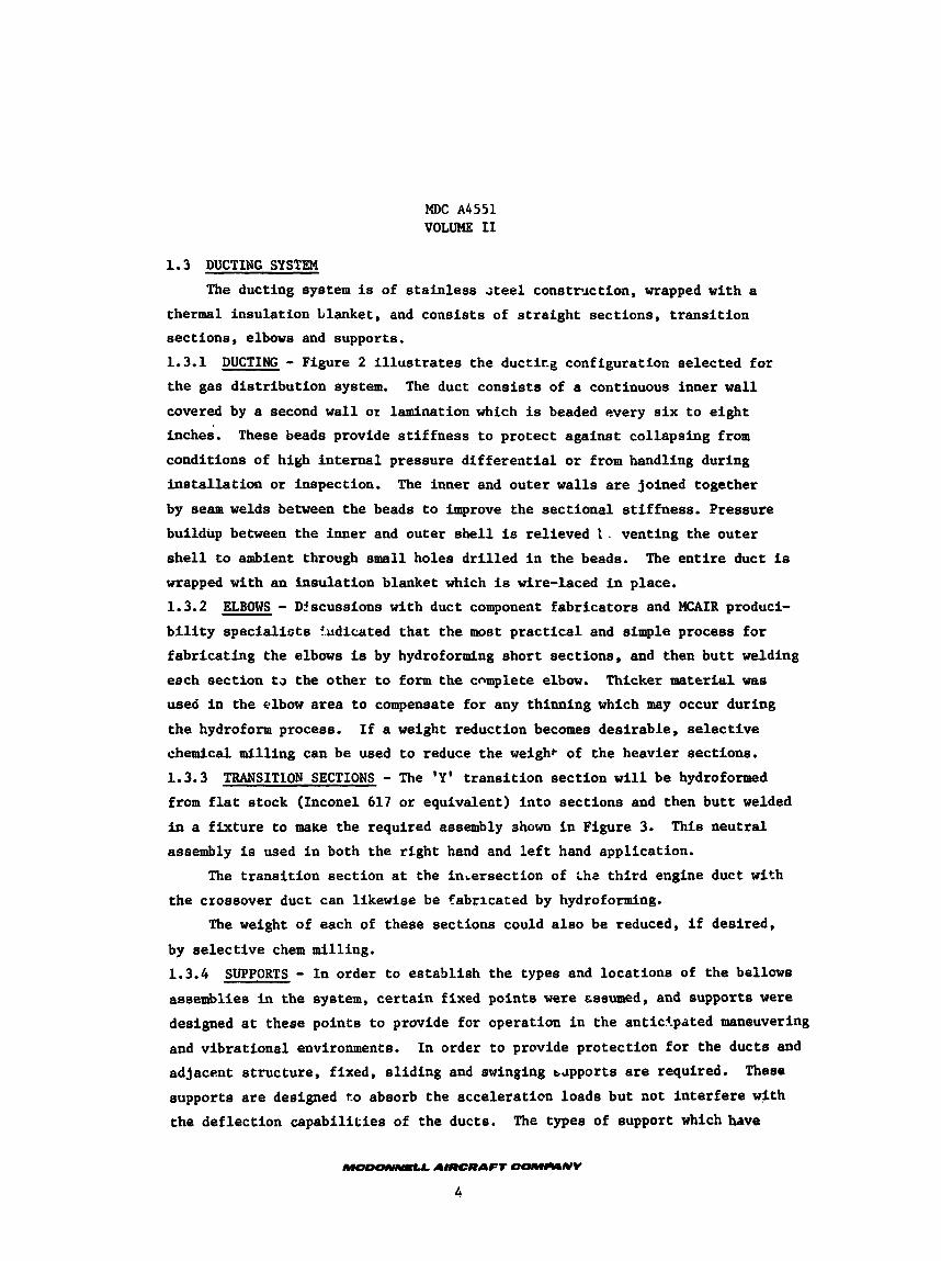
1.3 DUCTING SYSTEM The ducting system is of s t a i n l e s s steel cons tmct ion , wrapped with a
thermal insu la t ion blanket, and cons is t s of s t r a i g h t sec t ions , t r ans i t i on sect ions, elbows and supports.
1.3.1
t h e gas d i s t r ibu t ion system.
covered by a second w a l l or lamination which is beaded every s ix t o e ight
inches. These beads provide s t i f f n e s s t o pro tec t aga ins t col lapsing from
conditions of high i n t e r n a l pressure d i f f e r e n t i a l o r from handling during
i n s t a l l a t i o n o r inspection.
by seam welds between the beads t o improve the sectional s t i f fnes s . Pressure
buildup between t h e inner and outer s h e l l is rel ieved 1 , vent ing the outer
s h e l l t o ambient through small holes d r i l l e d i n the beads.
wrapped with an insu la t ion blanket which is wire-laced i n place.
1.3.2
b i l i t y s p e c i a l i s t s !.udicated t h a t t h e most p r a c t i c a l and simple process f o r
fabr ica t ing the elbows is by hydroforming shor t sect ions, and then b u t t welding
each sec t ion t a the o ther t o form t h e cnmplete elbow.
used i n the elbow area t o compensate for any thinning which may occur during
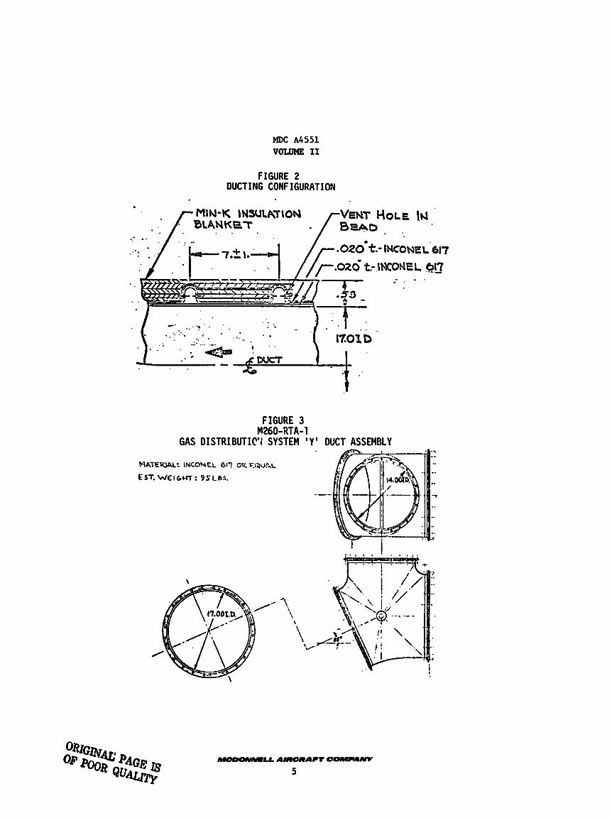
t h e hydroform process. I f a weight reduction becomes des i rab le , selective chemical mil l ing can be used t o reduce t h e weight of the heavier sections. 1.3.3 TRANSITION SECTIONS - The 'Y' t r ans i t i on sec t ion w i l l be hydroformed
from f l a t s tock (Inconel 617 o r equivalent) i n t o sec t ions and then b u t t welded
i n a f i x t u r e t o make the required assembly ahown i n Figure 3. assembly is used i n both the r igh t hand and l e f t hand appl icat ion.
DUCTING - Figure 2 i l l u s t r a t e s the d u c t k g configuration selected fo r
The duct cons i s t s of a continuous inner w a l l
The inner and outer w a l l s are joined together
The e n t i r e duct is
ELBOWS - Dlscussions with duct component f ab r i ca to r s and MCAIR produci-
Thicker material w a s
This neu t r a l
The t r ans i t i on sec t ion a t the inLersection of tha t h i r d engine duct with
the crossover duct can l ikewise be fabricated by hydroforming.
The weight of each of these sect ions could a l s o be reduced, i f desired,
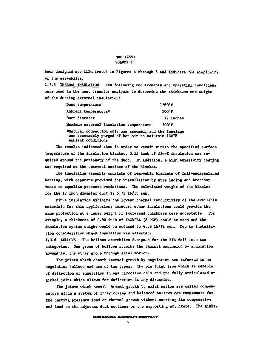
by se l ec t ive chem mill ing. 1.3.4 SUPPORTS - I n order t o e s t ab l i sh the types and loca t ions of the bellow8
assemblies i n the system, c e r t a i n f ixed poin ts were cssumed, and supports were designed a t these poin ts t o provide for operation i n the antic?.pated maneuvering
and v ib ra t iona l environments. adjacent s t ruc ture , f ixed, s l i d i n g and swinging aapports are required. These
supports are designed t o absorb the acce lera t ion loads but not i n t e r f e r e with
the def lec t ion capab i l i t i e s of the ducts,
I n order t o provide pro tec t ion for the duct8 and
The types of support which have
MDC A4551 VOLUME I1
FIGURE 2 DUCTING CONFIGURATION
. 020mt.- INCONE L'617
FIGURE 3
GAS DISTRIBUTIC'I SYSTEM ' Y ' DUCT ASSEMBLY M260-RTA-1
\
\
\ \#7
.. . I
!
MDC A4551 VOLUME I1
been designed are illustrated in Figures 4 through 8 and indicate the simpl%citp of the assemblies. 1.3.5 were used in the heat transfer analysis to determine the thickness ard weight of the ducting external insulation:
THERMAL INSULATION a- The following requirements and operating condicioncl
Duct temperature 1260'F Ambient temperature* lOO'F Duct diameter 17 Inches
Maximum external insulation temperature 300°F *Natural convection only was assumed, and the fuselage was constantly purged of hot air to maintain lCOOF ambient conditions
The result8 indicated that in order to remain within the specified surface temperature of the insulation blanket, 0.53 inch of rfin-K insulation was re- quired around the periphery of the duct. was required on the external surface of the blanket.
In addition, a high emissivity coating
The insulatian aasembly consists of remvab3.e blankets of foil-encapsulated batting, with capstans provided for installation by wire lacing and bre*+.her
vents to equaljze pressure variations. The calculated weight of the blanket for the 17 inch diameter duct is 5.72 lb/ft run.
Mln-K insulation exhtbits the lowest thermal conductivity of the available materials for this application; however, other insulations could provide the same protection at a lower weight $f increased thickness were acceptable. exaaqde, a thickness of 0.90 inch of KAOWOU (8 PCF) could be used and the insulation system weight would be reduced t a 4.33 lb/ft run. tion consideration Min-K insulation was selected. 1.3.6 BELLOWS - The bellows assemblies designed for the RTA fall into two categories. movements, the other group through axial motion.
For
Due to installa-
One group of bellcws absorbs the thermal expansion by angulation
The joints which absorb thermal growth by angulation are referred to as angulation bellows and are of two types.
of deflection or angulation in one direction only and the fully articulated or ginbal joint which al.lowe for deflection in any direction.
Thn, pin joint type which is capable
The joints which abaorb - h a m 1 grmth by axial motion are called compen- satore since a system of interlocking and balanced bellows can compensate for
the ducting pressure load or thermal growth without exerting its compressive end load on the adjacent duct sections or the eupporting etructure. The gimbai
FIGURE 5 SWINGING SUPPORl - LINKAGE
FIGURE 6 SWINGING SUPPORT - HINGE
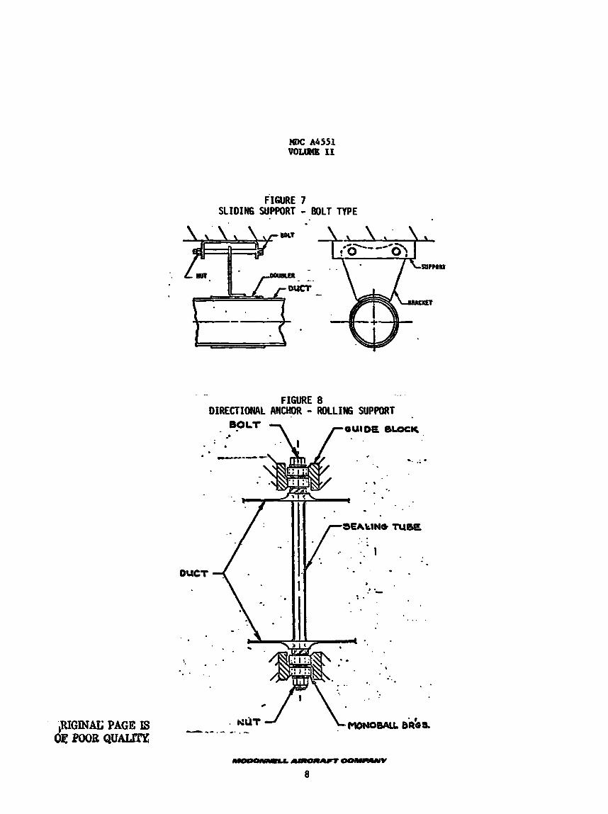
FIGURE 7 SLIDING SUPPORT - BOLT TYPE
... . FIGURE 8
OIRECTIONAL ANCHOR - ROLLIWG SUPPORT
DUCT
. .-',I . % . .
. . .
I 1 i I r I
i d
I
I
-. .; - E . :..-.:. . . 4 :
. ..
MDC A4551 VOLUME I1
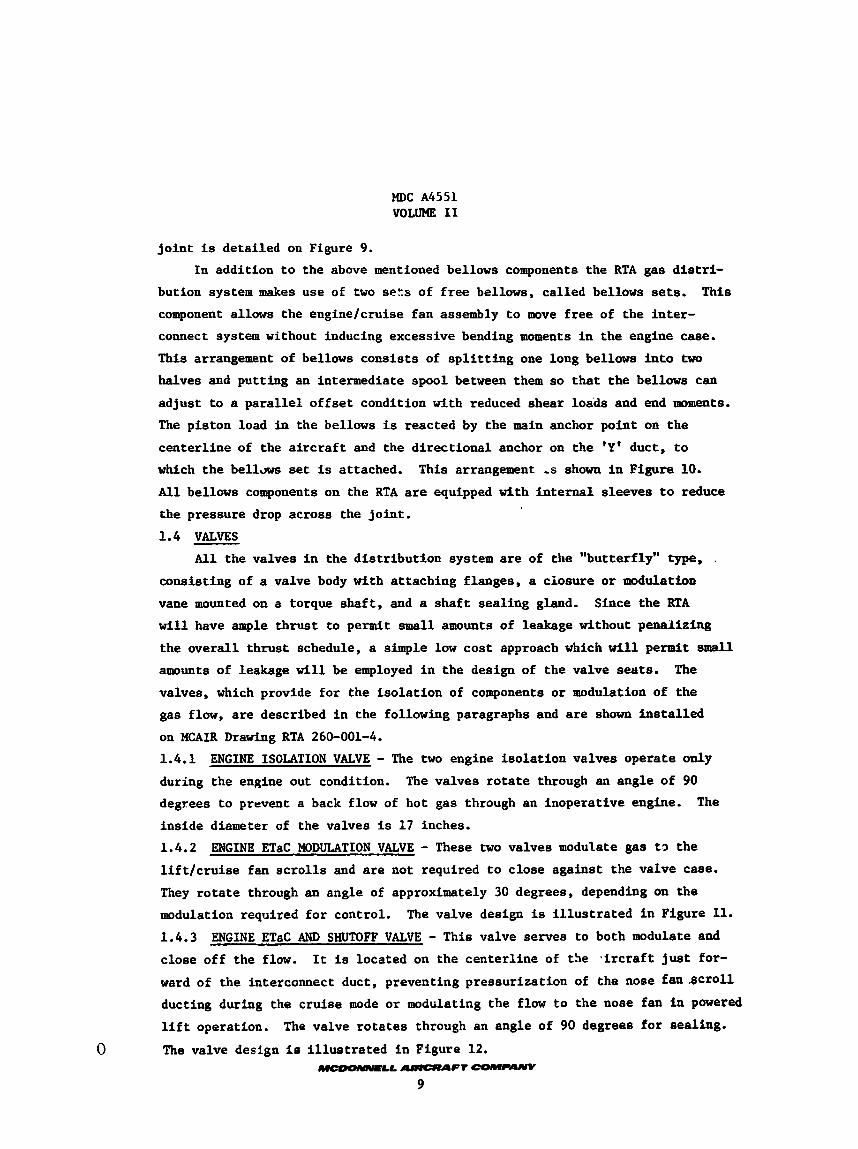
j o i n t is detai led on Figure 9.
In addi t ion t o the above mentioned bellows components the RTA gas d i s t r i -
bution system makes use of two sets of f r e e bellows, cal led bellows sets. This component allows the enginelcruise fan assembly t o move f r e e of the in te r -
connect system without inducing excessive bending moments i n the engine case. This arrangement of bellows cons is t s of s p l i t t i n g one long bellows i n t o two
halves and put t ing an intermediate spool between them so t h a t t he bellows can adjus t t o a p a r a l l e l o f f s e t condition with reduced shear loads and end moments.
The pis ton load in the bellows is reacted by the main anchor point on the
center l ine of the a i r c r a f t and the d i rec t iona l anchor on the 'Y' duct, t o
which the bellJws set is attached.
A l l bellows components on the RTA are equipped with i n t e r n a l s leeves t o reduce
the pressure drop across the jo in t .
1.4 VALVES
This arrangement s h a m i n Figure 10.
A l l the valves i n the d i s t r ibu t ion system are of the "butterfly" type, . consis t ing of a valve body with at taching flanges, a ciosure o r modulation
vane mounted on a torque sha f t , and a sha f t sea l ing gland.
w i l l have ample th rus t to permit s m a l l amounts of leakage without penalizing
the ove ra l l th rus t schedule, a simple low cos t approach which will permit s m a l l amounts of leakage w i l l be employed i n the design of the valve seats. The
valves, which provide fo r the i so l a t ion of components o r modulation of the
gas flow, are described i n the following paragraphs and are shown ins t a l l ed
on MCAIR Drawing RTA 260-001-4.
1.4.1
during the engine out condition.
degrees t o prevent a back flow of hot gas through an inoperative engine.
ins ide diameter of the valves i s 1 7 inches.
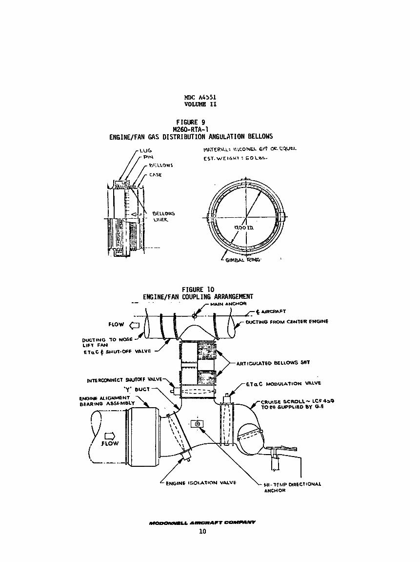
1.4.2
1 i f t J c r u i s e fan s c r o l l s and are not required t o c lose against the valve case. They r o t a t e through an angle of approximately 30 degrees, depending on the
modulation required f o r control.
1.4.3 close of f the flow. It is located on the center l ine of the Tircraft j u s t for-
ward of the interconnect duct, preventing pressurizat ion of the nose fan .Scroll
ducting during the c ru ise mode o r modulating the flow t o the nose fan i n powered
l i f t operation.
The valve design is i l l u s t r a t e d i n Figure 12.
Since the RTA
ENGINE ISOLATION VALVE - The two engine i so l a t ion valves operate only
The valves r o t a t e through an angle of 90
The
ENGINE ETaC MODULATION VALVE - These two valves modulate gas tr , the
The valve design is i l l u s t r a t e d i n Figure 11.
JNGINE ETaC AND SHUTOFF VALVE - This valve serves to both modulate and
The valve ro t a t e s through an angle of 90 degrees f o r sealing.
0 -L AlRCRIIPT EoMpL9Ny
9
HDC A4551 V O L W I1
FIGURE 9
ENGINEjFAN GAS DISTRIBUTION ANGULATION BELLOWS M260-RTA- 1
W\TER\t,L: \\:CONEL 617 OL CQUCL
EST.WEIrGU1~ t 6O\_%S-
FIGURE 10 ENGINE/FAN COUPLING ARRANGEMENT . -
MAIN ANCHOR -- - .
w)C A4551 VOLUME 11
FIGURE 11
ETaC MODULATION & GAS DISTRIBUTION VALVE F1260-RTA- 1
&xtowr *SAC A s u n
SHIFT SEN IN(^ GIAHO k s m . MAT€g\AL: \%ONEL tit7 OS EQJk
EST. WEIGHT: 6 0 C B S . IUWhTrOu 3puup ?hT. -z IRCONIA
CONTROL SHRFT
VALVE BLADE
---
CUT-OUT TO CLEAR SCROLL VALVE
-#A A-RAFT CoMpylWY
11
MDC A4551 VOLUME I1
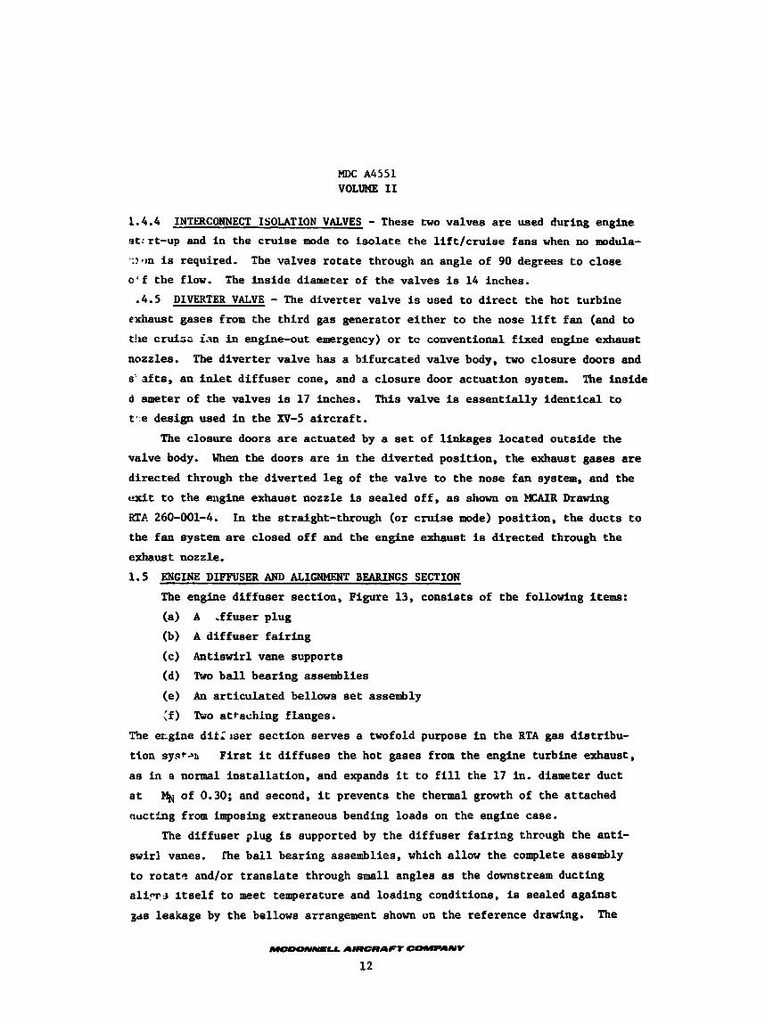
1.4.4 s t r r t -up and i n the c ru ise mode to I s o l a t e the l i f t / c r u i s e fans when no modula-
':?fm is required.
o ' f t he flow. The in s ide diameter of the valves is 14 inches.
INTERCONNECT ISOLATION VALVES - These two valves a r e used during engine
The valves r o t a t e through an angle of 90 degrees t o c lose
.4.5 DIVERTER VALVE - The diver te r valve is used t o d i r e c t the hot turbine
e x h a u s t gases from the th i rd gas generator e i t h e r t o the nose l i f t fan (and t o
the cruise ran in engine-out emergency) o r tc conventional f ixed engine exhaust
nozzles. The d ive r t e r valve has a bifurcated valve body, two closure doors and
s ' a f t s , an i n l e t d i f fuse r cone, and a closure door actuat ion system.
d ameter of the valves is 17 inches.
t . e design used in the XV-5 a i r c r a f t .
The ins ide
This valve is essen t i a l ly iden t i ca l t o
The closure doors are actuated by a set of linkages located outs ide the
valve body.
directed through the diver ted l e g of the valve to the nose fan system, and the
exit t o the engine exhaust nozzle is sealed o f f , as shown on MCAIR Drawing
RTF. 260-001-4. In the straight-through (or cruise mode) posi t ion, the ducts t o
the f an system are closed of f and the engine exhaust is directed through the
exhaust nozzle.
When the doors are in the diver ted posi t ion, the exhaust gases are
1.5
The
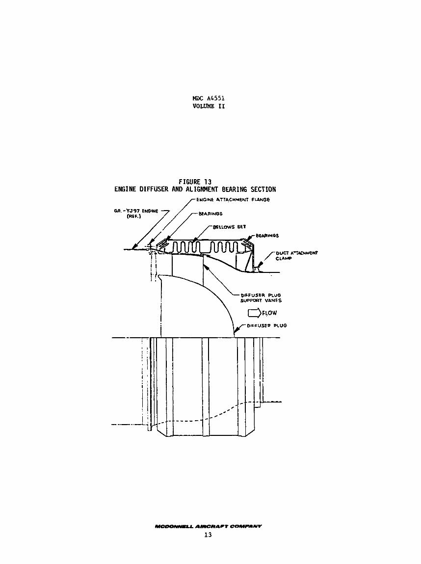
ENGINE DIFFUSER AM) ALIGNMENT BEARINGS SECTION The engine d i f fuse r sect ion, Figure 13, cons is t s of the following items:
(a) A .ffuser plug
(b) A d i f fuse r f a i r i n g
(c) Antiswirl vane supports
(d) Two b a l l bearing assemblies
(e) [ f ) Two at tachfag flanges.
An a r t i cu la t ed bellows set assembly
ecgine dit:iaer sec t ion serves a twofold purpose i n the RTA gas d is t r ibu-
t ion sy.s+-.n
a s i n a normal i n s t a l l a t i o n , and expands it t o f i l l the 17 in. diameter duct
a t
aucting from imposing extraneous bending loads on the engine case.
F i r s t it d i f fuses the hot gases from the engine turbine exhaust,
% of 0.30; and second, i t prevents t he thermal growth of t he attached
The d i f fuser plug is supported by the d i f fuse r f a i r i n g thrcugh the ant i - s w i r l vanes.
t o rotatc, and/or t r ans l a t e through small angles as the downstream ducting a l i .ms i t s e l f t o meet temperature and loading conditions, is sealed against
sds leakage by the bellows arrangement shown on the reference drawing. The
fhe b a l l bearing assemblies, which allow the complete assembly
w)C A4551 VOLUME I1
FIGURE 13 ENGINE DIFFUSER AND ALIGNMENT BEARING SECTION
ENGINC ATTACHMENT FLANGE
GE.
: I ! $ 1 . . . . I
: I i I '
q i
* I * .
' i i / ' ! I \ 1 -..--.d
SUPPORT VANES \ -~PFuJhA
i JL
P U AllIERIICt -NV
13
MDC A4551 VOLUME 11
pressure piston load in the bellows is reacted by the cylindrical shell sup-
porting the outer races of the bearings keeping the component in equilibrium. 1.6 COMPONENT MATERIALS SELECTION
The maximum duct system operating temperature of 1375OF and normal opera- ing temperature of 1260°F makes available a variety of materials which have the
required characteristics of supericr corrosion resistance, resistance to creep, high stress rupture strength, and superior oxidation resistance. These service temperatures are more significant with respect to long term metallurgical sta- bility since this is in the range conducive to carbidL precipitation and the formation of brittle intermetallic phases.
were screened as possible component materials, including the following: A number of available superalloys
21-6-9 Inconel X-750 . N-155 (Multimet) Inconel 718 Inconel 600 Hastelloy X Inconel 601 Haynes 188 Rae' 41 Inconel 625
Inconel 718 Inconel 617 L-605
The austenitic 21-6-9 is one of the new stainless steels offering better Its oxidation resistance I s more than adequate strength than the 18-8 class.
for the application; but even with its low carbon content, there is a tendency for carbides to precipitate with long time exposure at the service temperature. This behavior would result in reduced intergranular corrosion resistance and
ductility. Strength; and since welding reduces the local area to annealed properties, the alloy is not competitive for welded applications. quires welding, 21-6-9 offers little advantage over the 18-8 stainless steel
grades.
Typically, 21-6-9 is used in a cold worked condition for improved
Since this application re-
For these reasons, 21-6-9 was not attractive for this application.
N-155 is one of the oldest superalloys and contains roughly 20% each of chromium, nickel and cobalt. the service temperatures, but its high carbon content raises the question of
intergranular corrosion resistazce and ductility after long time elevated temperature exposure. While it would probably perform satisfactorily In this
application, it is not judged competttive with the other candidate materials.
It has excellent oxidation resistance well above
Inconel 600 and 601 exhibit superior oxidation resistance to temperatures above 2000°F, but they have low strength. Typical application8 for these alloys
MDC A4551 VOLUME I1
are therefore nonstructural, such as heat-treating baskets, fixtures.and furnace components. of oxidation resistance and metallurgical stability, but they would not be weight competitive with the other higher strength candidate alloys.
They both would be more than adequate for the application in.terms
The remaining alloys can be divided into two classes: those which are Strengthened through precipitation heat treatment and those that are solid solution strengthened.
"he precipitation hardening alloys included Rene' 41, Inconel 718, and Inconel X-750 but the higher strength they offer is offset somewhat by the difficulty experienced in fabrication. The aging treatment required after fabrication creates a distortion problem which is related t o the complexity of the formed part.
moMt complex parte, the increased fabrication costs will make their use im- practical. As with the previous alloys, these exhibit more than adequate oxidation resistance and metallurgical stability for the RTA application. service temperature, 1260°F, approximately represents the limit for long term exposure of Inconel 718.
For simple parts, use of these alloys may be feasiFle; for
The
The solid solution strengthened alloys are much easier to fabricate into complex structures, because they require no thermal treatment after forming or welding. The alloys in this category include Hastelloy X, Haynes 188, Inconel 625, Inconel 63.7, and 6605. Any of these alloys, all of which are readily available, will function satisfactorily in the system environment.
.
. -
#' ORIGINAEPAGEIS OF POOR QUALITY -.
I
,
. .. 4 ' - -. -
. v . .
.. b
! i 1 , .
I
-
I
. I _.
I
I . . - - . .. I
/
--
.I: ;
..
a. . . ---t-- -,
---- - . . !
. , . * . ! -. . 1
I . . 1. ' i , . 1 . - . /e--
- /
. . . . . I . .
. - - . I - --. . . * - .. . ..- -. . . * .
_ . I --. - ' -. - - -. \. . . ~ , - - .. . - . * . . I. - .
' e ; 1 : .. ... - _ . . . . - , . . . . . . . .*
. . . . .
I: . .
. . L
I '
I :
. . ~ . . . .- . - . . . - . - ---. .-I-- ._.-. .. . . ' . c
I . .
I f .
.* .
. . e .
. - . -
. . I -
.- @
- .
,
.
..
a
MDC A4551 VOLUME iI
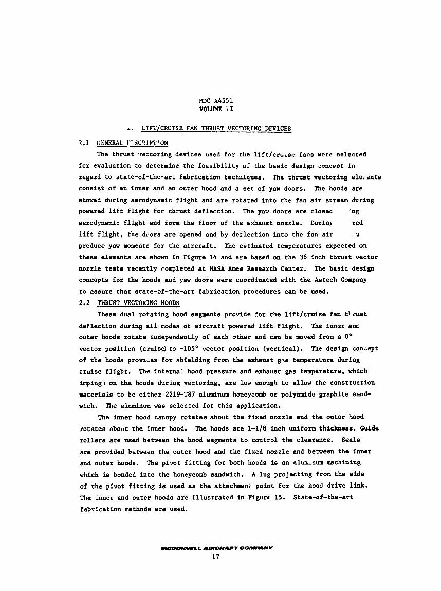
A. LIFT/CRUISE FAN THRUST VECTORING DEVICES
?. 1 GENERAL !"-.SCXIPT'
The th rus t vectoring devices used f o r the l i f t / c r u i s e fane were selected f o r evaluation t o determine the f e a s i b i l i t y of the bas ic design concent i n
regard t o state-of-the-art fabr ica t ion techniques.
consis t of an inner and an outer hood and a set of yaw doors.
stow& during aerodynamic f l i g h t and are ro ta ted i n t o the fan air stream during
powered l i f t f l i g h t fo r th rus t def lect ion.
aerodynamic f l i g h t and form the f loo r of the Exhaust nozzle.
The th rus t vectoring ele, en ts
The hoods are
The yaw doors are closed
During 'ng red
l i f t f l i g h t , the doors are opened and by def lec t ion i n t o the fan air .3
prcduce yaw moments f o r the a i r c r a f t .
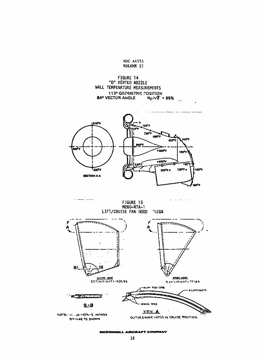
these elements are shown i n Figure 14 and a r e based on the 36 inch th rus t vector
nozzle tests recent ly rompleted a t NASA Ames Research Center.
concepts f o r the hoods and yaw doors were coordinated with t h e &tech Company
t o assure tha t state-of-the-art fabr ica t ion procedures can be used.
2.2 THRUST VECTORING HOODS
The estimated temperatures expected 03
The bas ic design
These dual ro t a t ing hood segments provide f o r t he l i f t / c r u i s e fan t ' rust def lec t ion during a l l modes of a i r c r a f t powered l i f t f l i g h t .
ou ter hoods r o t a t e independently of each o ther and can be moved from a 0"
vector posi t ion (cruise) t o -105" vector pos i t ion (ver t ica l ) .
of t h e hoods proviLes f o r sh ie ld ing from the exhaust g?.s temperature during
c ru i se f l i g h t .
imping? on t h e hoods during vectoring, are low enough t o allow the construction
materials t o be e i t h e r 2219-T87 aluminum honeycomb o r polyamide graphi te sand-
wich.
The inner a n t
The design conLept
The i n t e r n a l hood pressure and exhaust gas temperature, which
The aluminum was selected f o r t h i s application.
The inner hood canopy r o t a t e s about the fixed nozzle and the outer hood
r o t a t e s about the inner hood. The hoods are 1-1/8 inch uniform thickness. Guide
r o l l e r s are used between the hood segments t o control the clearance.
are provided between the outer hood and the fixed nozzle m d between the inner
and outer hoods.
which is bonded i n t o the honeycomb sandwich.
of t he pivot f i t t i n g is used as t h e attnchmen; point f o r the hood dr ive link. The inner and outer hoods are i l l u s t r a t e d i n Figurc 15.
fabr ica t ion methods are used.
Seals
The pivot f i t t i n g €or both hoods is an slurt~num machining
A lug 2roJect ing from the s i d e
State-of-the-art
W-LL AlRCRAFI COMI40NV
17
MDC A4551 VOLUME I1
FIGURE 14 'ID" VENTED NOZZLE
WALL TEMPERATURE MEASUREMENTS 11 2 O GEOMETRIC ?OSITION
.._. 840 VECTOR ANGLE NF/* = 95%
__ - . . . -. . .
FIGURE 15
LIFT/CRUISE FAN HOOD ' -!;IGN M260-RTA-1
MDC A4551 VOLUME I1
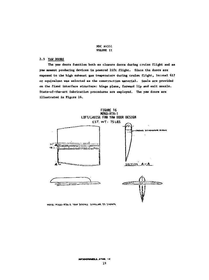
2.3 YAW DOORS
The yaw doors function both as closure doors during c ru i se f l i g h t and as yaw moment producing devices i n powered l i f t f l i g h t .
exposed to the high exhaust gas temperature duxins cru ise f l i g h t , Inconel 617
or equivalent was selected as the construction material. on t h e f ixed interface s t ructure: hinge plane, forward l i p and exit nozzle.
State-of-the-art fabr icat ion procedures are employed.
i l l u s t r a t e d i n Figcre 16.
Since the doors are
Seals are prwided
The yaw doors are
I.
MDC A4551 VOLUME I1
3. MECHANICAL TRANSMISSION SYSTEM
3.1 GENERAL DESCRIPTION
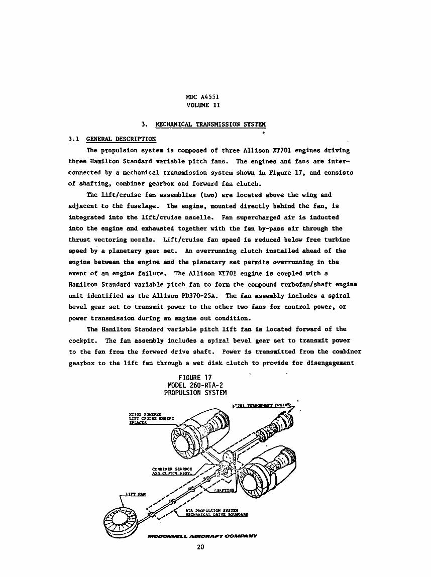
The propulsion system is composed of three Allison XT701 engines dr iving
The engines and fans are inter- three Hamllton Standard var iable p i t c h fans.
connected by a mechanical transmission system shown i n Figure 17, and cons i s t s
of shaf t ing, combiner gearbox and forward fan clutch.
The l i f t / c r u i s e fan assemblies (two) are located above t h e wing and
adjacent t o the fuselage.
integrated i n t o t h e l i f t / c r u i s e nacelle.
i n t o the engine and exhausted together with the fan by-pass air through the
t h r u s t vectoring nozzle.
speed by a planetary gear set. engine between the engine and the planetary set permits overrunning in the
event of an engine fa i lure .
Hamilton Standard var iable pi tch fan t o form the compound t u r b o f a d s h a f t engine
u n i t i den t i f i ed as the Allison PD370-25A.
bevel gear set t o transmit power t o the other two fans f o r control power, o r
power transmission during an engine out condition.
The engine, mounted d i r e c t l y behind the fan, is Fan supercharged air is inducted
L i f t / c r u i s e fan speed is reduced below f r e e turbine
An overrunning clutch i n s t a l l e d ahead of the
The Allison XT701 engine is coupled with a
The fan assembly includes a s p i r a l
The Hamilton Standard var iable p i t c h l i f t fan is located forward of the
cockpit.
t o the fan from the forward dr ive shaf t . Power is transmitted from the combiner
gearbox t o the l i f t fan through a w e t disk clutch t o provide f o r disengagement
The fan assembly includes a s p i r a l bevel gear set t o transmit power
FIGURE 17
PROPULSION SYSTEM MODEL 260-RTA-2
COUBINER GFARBOX
20
MDC A4551 VOLUME I1
of the fan during ground operation, i f desired, o r i n the c ru ise mode.
The t h i r d engine (center) dr ives i n t o the combiner gearbox through a spur
gear set i n t o the transmission system. The combf-er gearbox a l s o accepts power from the two l i f t / c r u i s e engines f o r d i s t r i b u t i r - during control excursions and
engine out operation.
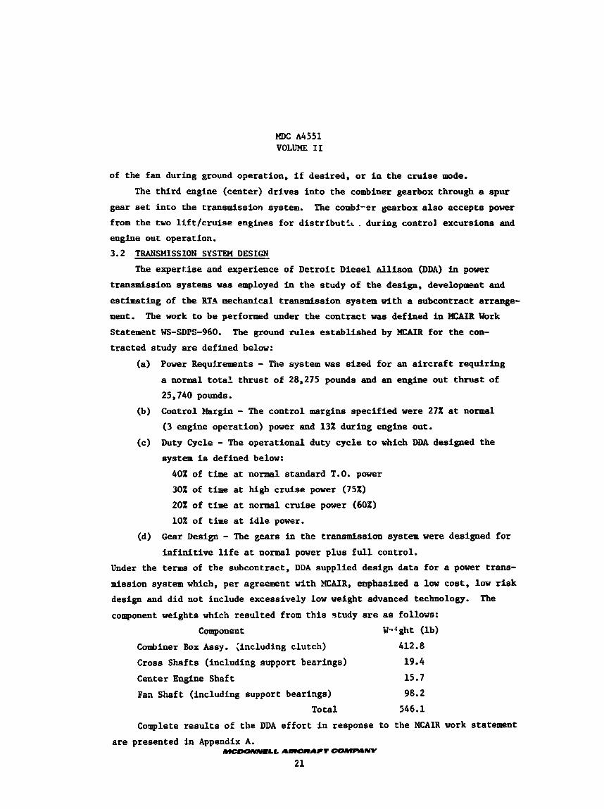
3.2 TRANSMISSION SYSTEM DESIGN
The exper t i se and experience of Detroi t Diesel Allison (DDA) in power
transmission systems w a s employed in the study of t he design, development and
estimating of the RTA mechanical transmission system with a subcontract arrange- m e n t .
Statement WS-SDPS-960.
t rac ted study are defined below:
The work t o be performed under the contract was defined i n MCAIR Work
The ground rules establ ished by MCAIR fo r t he con-
(a) Power Requirements - The system w a s s ized f o r an a i r c r a f t requir ing
a normal t o t a l t h rus t of 28,275 pounds and an engine out thrust of
25,740 pounds.
Control Margin - The control margins specif ied were 27% a t normal
(3 engine operation) power and 13% during engine out.
Duty Cycle - The operat ional duty cycle t o which DDA designed the
system is defined below:
(b)
(c)
40% of time a t normal standard T.O. power
30% of t i m e a t high c ru ise power (75%) 20% of time a t normal c ru ise power (60%)
10% of t i m e a t i d l e power.
(d) G e a r Design - The gears i n the transmission system were designed fo r
i n f i n i t i v e l i f e a t normal power p lus f u l l control.
Under the terms of the subcontract, DDA supplied design da ta for a power trans- mission system which, per agreement with MCAIR, emphasized a l o w cos t , low r i s k design and did not include excessively low weight advanced technology.
component weights which resul ted from t h i s study are as follows: Component W-f ght ( lb)
The
Combiner Box Assy. (including clutch) 412.8
Cross Shafts (including support bearings) 19.4
Center Engine Shaft 15.7
Fan Shaft (including support bearings) 98.2
Total 546.1
Complete r e s u l t s of t he DDA e f f o r t i n response t o the MCAIR work statement are presented i n Appendix A.
-ma. AHWCRAPT COMFWNV
2 1

I9DC A 4 5 5 1 Volume I1
APPENDIX A
MCI)ONNELL AIRCRAFT COMPANY V/STOL RTA SHAPT AND TRANSMISSION DESIGN STUDY
By
DETROIT DIESEL ALLISON
A-1
MDC A4551 Volume I1
oetrpn DieSglNliaga omton 01 G e n m tors coruoretlan
ineimnamtis. tndtana 46206
MC DONNELL AIRCRAFT COMPANY V/STOL RTA SHAFT
AND TRANSMISSION SYSTEM DESIGN
STUDY
EDR 8 9 7 6
Part I
November 1 5 7 6
A-2

MDC A4551 VOLUME I1
1.0 Introduction
This report w a s Trcnarcd in response to ticUoniie11 Aircraf t Go. (MCALR) Purchase Or-:er Z6OC91 vnnrz'r? 9eetroit Diesel Allison (3DA) w a s t o conduct a propulsion sys ten r:ocf..ncip-i Zransmission study for the V/STOL-Research and Technology k.5rcrz.r: {RTA!. The complete wr i t ten response by DDA in- cludes t h i s report (P3z-c i ) ri-d P a r t 2 covering estimated cos t s of a shaft. s y s t e m developmext pro.cr3r.i.
"he e f f o r t described herein w a s accomplished during the per iod July-August 1976 m d e r the DDA Pro jec t Ninnber E76030.
The RTA V/STOL a i r c r a f t incorporates a propulsion s y s t e m ae shown i n Figure 1.1.
This study has as its objec t ives the i d e n t i f i c a t i o n of technical risks and preparation of estimates f o r design, fabr ica t ion and t e s t i n g of assemblies and components f o r a research and technology a i r c r a f t propulsion system mechanical transmission. The components t o be covered are those shown i n Figure 1.1 and i d e n t i f i e d a s combiner box and c lu tch and the four sha f t s leading to the combiner box.
2 .o
2.1
Design study
A design study w a s conducted to def ine a sha f t ing system i n the d e t a i l ade- quate t o iden t i fy technical r i s k s and estimate costs f o r design, fabrica- t i on and t e s t ing . This design study is defined herein.
Power and Speed Requirements
Pr ior t o the ac tua l sha f t ing system design e f f o r t , i t w a s necessary t o obtain estimates fo r RTA s y s t e m powers and speeds. This e f f o r t was conducted at DDA making use of t h e known data f o r a Hamilton Standard 62" varlable-pitc4i fan and the DDA XT701 engine. The s t a r t i n g p o i n t for t h l n effort wrin I t i t .
required th rus t and control t h r u s t margin e s t ab l I ~ h e d by M:hlK
0 Total Thrust Required (normal) 28,275 l b s . (margin 22x1
0 Total Thrust Required (1 engine out) 2 5 , 7 4 0 lbs . (marpin If)?)
These th rus t l eve l s a r e t o be achieved on 90°F day a t sea l eve l s t a t i c condi- t ions . be f l a t rated below 900F and tha t sha f t horsepower would therefore not exceed those determined fo r the s t a t ed conditions.
Performance calculat ions were made €or the RTA system fo r V.T.O. operation with three engines operat ional and with an outboard engine out.
It was assumed fo r the purpose of t h i s study tha t the engines would
A-3

MDC A4551 VOLUME I1
OstrpIt Diesel Allison Onrldon ol General Motors Coqtomtlon
ItulmnawUS. Indiana 46206
A-4
MDC A4551 VOLUME 11
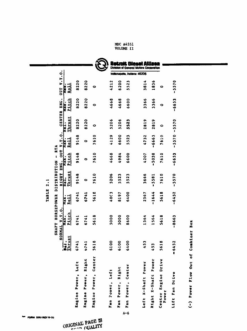
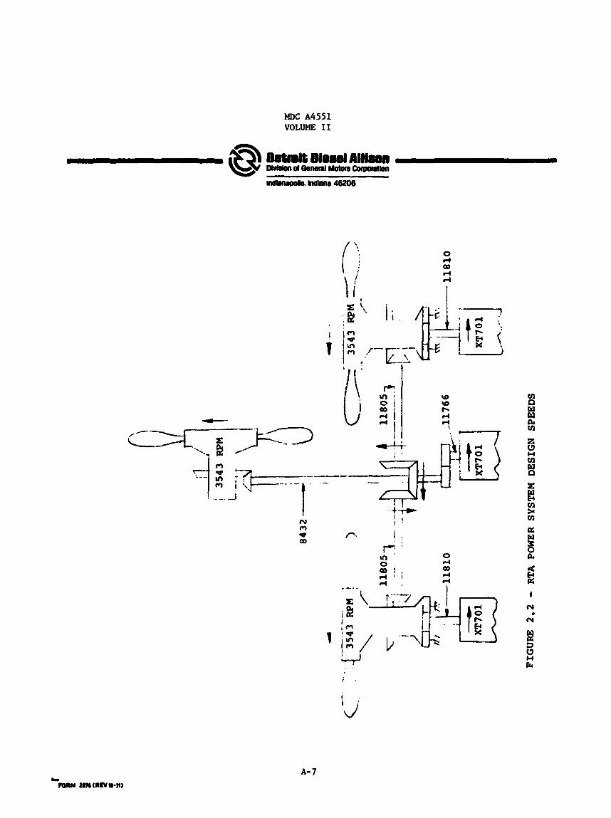
These ca lcu la t ions were then extrapolated t o the nine conditione shown ia Table 2.1 and sha f t horsepower was determined f o r each component i n the sha f t ing system.
Actual mechanical design speeds f o r the RTA to be used In t h i s study were es tab l i shed in the following manner.
1.
2.
3.
4.
The 100% mechanical fan speed w a s set at 3,543 WM.
The reduction gear f o r t he l i f t / c r u i s e engines w a s assumed to be the T56 planetary set with a r a t i o of 10:3. 100% l i f t cruise power turb ine speed a t 11,810 RPM.
Cross sha f t ing from the l i f t / c r u i s e engines t o the combiner box was set close t o power turbine speed - 11,805 RPM.
This es tab l i shed the
The input speed to the l i f t fan gear box was determined t o be 8,432 RPU based on t he l i f t fan gearbox ratio of 2.38:l es tab l i shed i n earlier s t u d i e s and coordinated v i t h Hamilton-Standard and McDo&ell- Douglas.
Figure 2.2 is A schematic showing the RTA power system speeds (100% design point) f o r each poin t i n the system.
Although o ther speeds could have been se l ec t ed f o r each component In this study, i t is believed t h a t the overall resultb would be the same relative t o conclusions on costs, risk and development time.
2.2 Combiner Gearbox Design
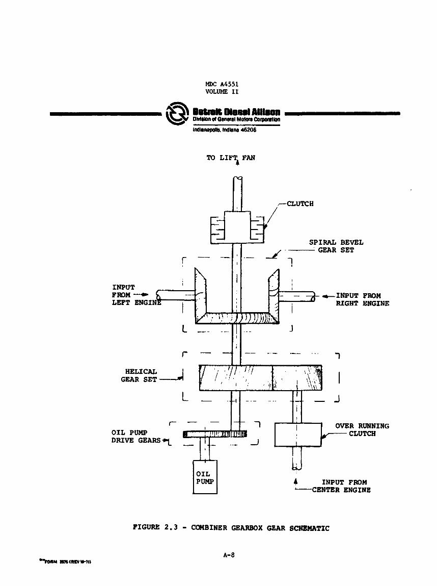
2.2.1 General Arrangement and Function
The combiner box t r ans fe r s power from three engines t o the three fane during the powered l i f t mode. is disengaged by the combiner box clutch; the combiner box clutch accel- erates the l i f t fan t o operat ing speed p r i o r t o powered l i f t o f f and during t r a n s i t i o n from conventional f l i g h t t o the powered l i f t mode.
During conventional f l i g h t the l i f t fan
The center engine input t o the conblner box is through a set of h e l i c a l gears with a 1 . 4 : l reduction r a t i o . (See Figure 2.3.) The output gear of t h i s set mounts d i r ec t ly on the s h a f t d r iv ing folward to the l i f t fan. Each outboard engine is coupled t o the l i f t fan sha f t with a r igh t angle set of s p i r a l bevel gears ; reduction r a t i o of 1 . 4 : l . gear is mounted d i r e c t l y on t h e sha f t d r iv ing forward t o t h e l i f t fan. Output from the combiner box t o t h e l i f t fan is through a disk clutch provided with a mechanical lockup f o r f u l l power transmission. The com- b iner box is provided with i t s own lubr ica t ion and cooling system, the oil cooler being the only airframe equipment.
Here again the output
Controls for clutch actuat ion
A-5
MDC A4551 VOLUME I1
0 N N 00
0 N N 00
0 N N 00
00 U
OI d
00 U
br d
a0 U
0, d
d U r- 9
4 U r- 9
d .d I- 9
Y W Q) cl
Lc Q)
pc
0)
r( M 0 01
g
a
0 N hl 03
0 N N 00
0 N hl 03
0
0
0
d U b 9
d U r- 9
d U h 0
U A 00 r( oc
Lc a! 3 0 al Q)
cl Y 0 Y
.)
a
0
0
0
0 d
9 r-
0 d d h
O 4 d h
Q)
9 IP
d
00
\o In
4
a0
9 In
H
Lc P) Y c 9) W
n Lc 91 : a 91
l4 00 0 Y
a
hl d (Y U
03 9 9 V
9 0 N In
Q, N
U d
a0 9 9 U
9 0 N In
m c, 0 U
0 0 (Y d
Qo 9 9 e
9 0 N In
0 0 9 \o
U 00 OI U
m N In In
h OI r(
00
m (Y In In
0 0 9 \o
c3 Y m u)
m (Y In M
0 0 9 9
m N In In
0 0 U 9
0 0 0 0 0 0 0 0 9 I n m a
0 0 0 0 0 0 d 4 U 9 9 9
U
00 m
4
\o
m m
Q, d 00 N
N m r- U
h 0 hl U
9 9 9 m
r- 9 In N
U 9 In r(
m In U
9 m 00 d
9 9 m m
0,
00 N
d
CCI 9 9 9 I
00 m 0 In I
d QD In In I
U U 9
I d
U 9 In d
p3 In U
Lc P) 3 0
pc
U W 0 E VJ I
b4
U s eo cl pb
0
0
0
G 4 rg h
0 d 9 h
0 4 9 b
00
9 In
d
00
9 In
d
0 h VI In I
cr) M
9 I
0 h In In I
0 h In In I
rn In 9 9 I
0 h In In I
N In U 9 I
m 9 9 00 I
00 F) r ) In 9 U In 9
8
n I Y
MDC A4551 VOLUME I1
i i .
E::-
-1
t - t i t N m * Eo
B VI >( cn
I N
N c
i
A- 7
MDC A4551 VOLUME I1
f
I
To LIFT FAN 4
1 . 1 A
-INPUT RIGHT
HELICAL GEAR SET
BEVEL SET
r OIL PUMP DRIVE G E A R S 7
FROM ENGINE
7 -1 OVER - CLUTCH RUNNING
INPUT FROM CENTER ENGINE
4 I
FIGURE 2.3 - COMBINER GEARBOX GEAR SCHEMATIC
A-a
MDC A4551 VOLUME I1
Datanit Diesel Allison Olvldon of General Motors Corporation
IndIanaDob. lndrna 46206
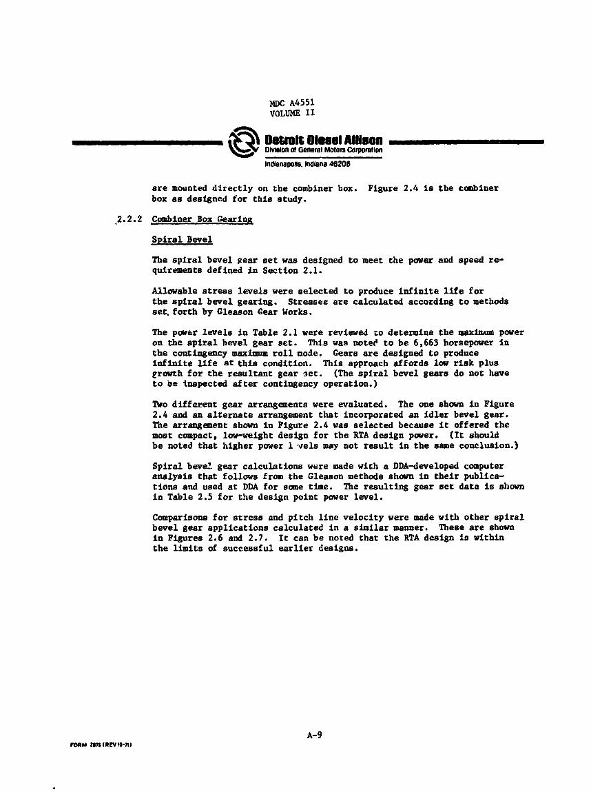
are mounted d i r e c t l y on the combiner box. box as designed f o r t h i s study.
Figure 2.4 is t h e canbiner
,2.2.2 Combiner Box Gearing
S p i r a l Bwel
The s p i r a l bevel gear set w a s designed t o meet the power and speed re- quirements defined i n Section 2.1.
Allowable stress levels were se lec ted t o produce i n f i n i t e l i f e f o r t h e s p i r a l bevel gearing. set. f o r t h by Gleason Gear Works.
Stressee a r e calculated according t o methods
The pawrr levels in Table 2.1 were reviewed zo determine the maxiatrrm power on the s p i r a l bevel gear set. t h e contingency maximum r o l l mode. i n f i n i t e l i f e a t t h i s condition. eruwth for t he r e su l t an t gear set. t o be inspected a f t e r contingency operation.)
This w a s not& t o be 6,663 horsepower i n Gears are designed t o produce
This approach af fords low r i s k plus (The s p i r a l bevel gears do not have
!ho d i f f e ren t gear arrangements were evaluated. 2 .4 and an alternate arrangement that incorporated an i d l e r bevel gear , The arrangement shown i n Figure 2 .4 was selected because i t offered the most compact, low-weight design f o r the RTA design parer. be noted t h a t higher power 1 vels may not r e s u l t i n t h e same conclusion.)
The one shown in Figure
(It should
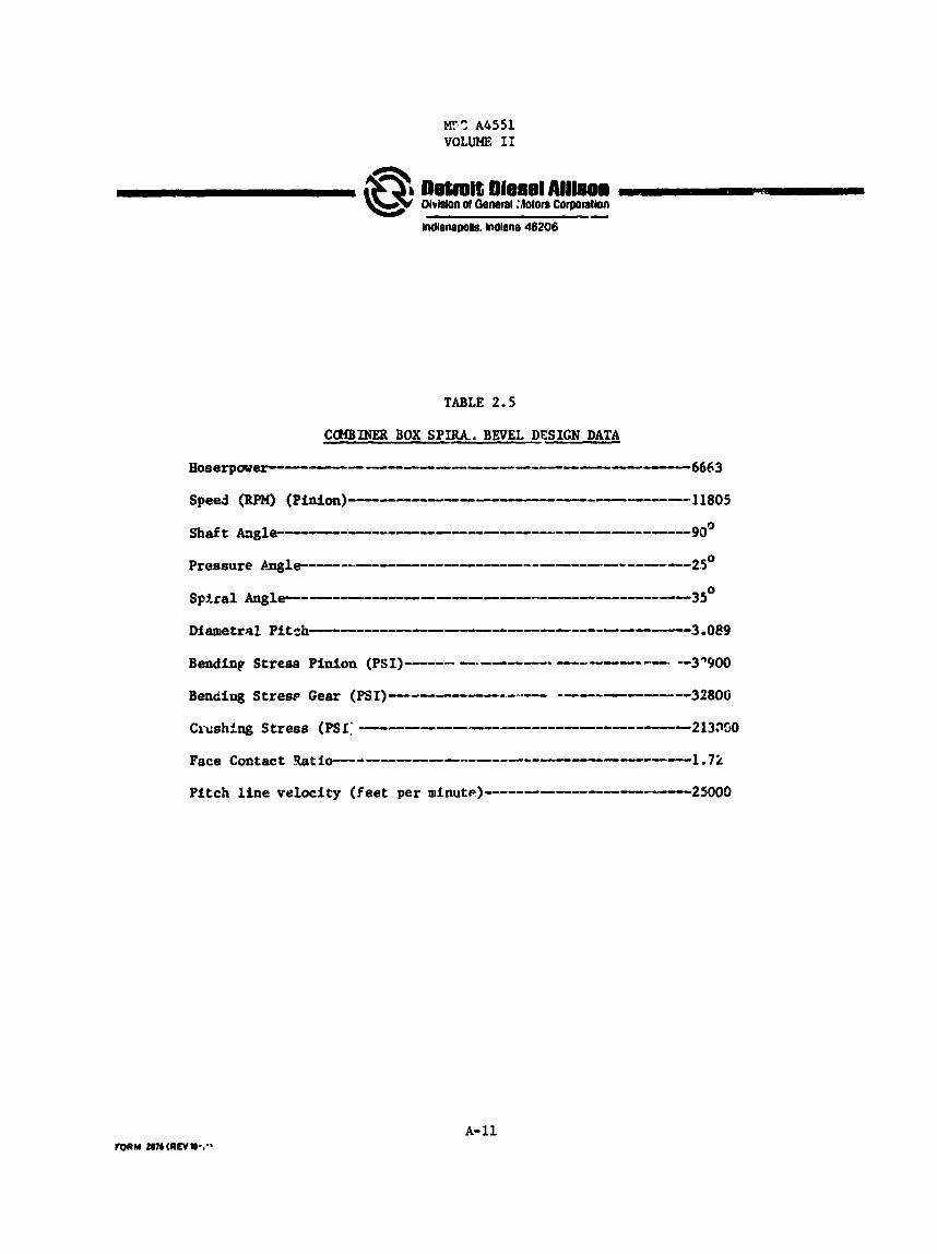
Sp i r a l beve: gear calculat ions were made with a DDA-developed computer ana lys i s tha t follows from the Gleason methods shown i n t h e i r publica- tions and used at DDA f o r same time. in Table 2.5 f o r t h e design point power level.
The resu l t ing gear set da ta is shown
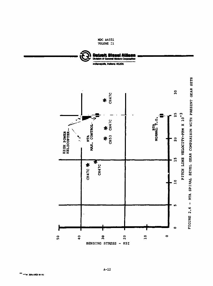
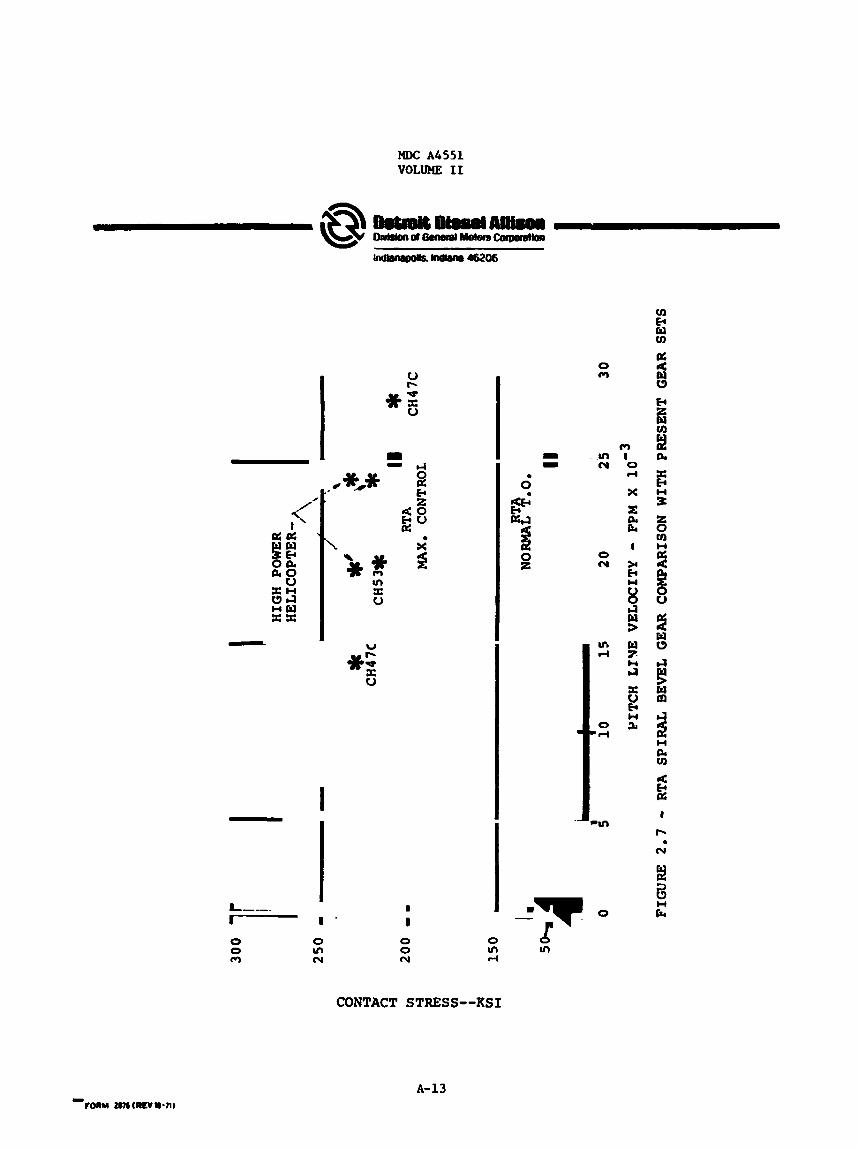
Comparisons f o r stress and p i tch l i n e ve loc i ty were made with other s p i r a l bevel gear appl ica t ions calculated i n a s imi la r manner. i n Figures 2.6 and 2 . 7 . t h e l i m i t s of successful e a r l i e r designs.
These a r e shown It can be noted tha t the RTA design is within
MDC A4551 VOLUME I1
A- 10
~sl;roit Diesel Alllson Dlvlslon ol General :lotom Corgoratlon
Indlanapolk Indiana 46206 -
A-11
Nw: A6551 YOLUNE 11
x x
0 v1
* 0 V X V
I- v x
0 m
0 N
0 m
BENDING STRESS - KSI 0 rl
0
A-12
M#: A6551 VOLUME I1
0 m
m E H a X f3 n 3
m I 0 rl
X
E PI E
a X I
* k
2 w t3 W
7: cc ta 4
w s m 3: u
k w ad 3 U
PI tn
I
3
Q z a
I
0 m cu
I 0 0 0 m cu d
A m
CONTACT STRESS--KSI
A-13

?fDC A4552 VOLUME I1
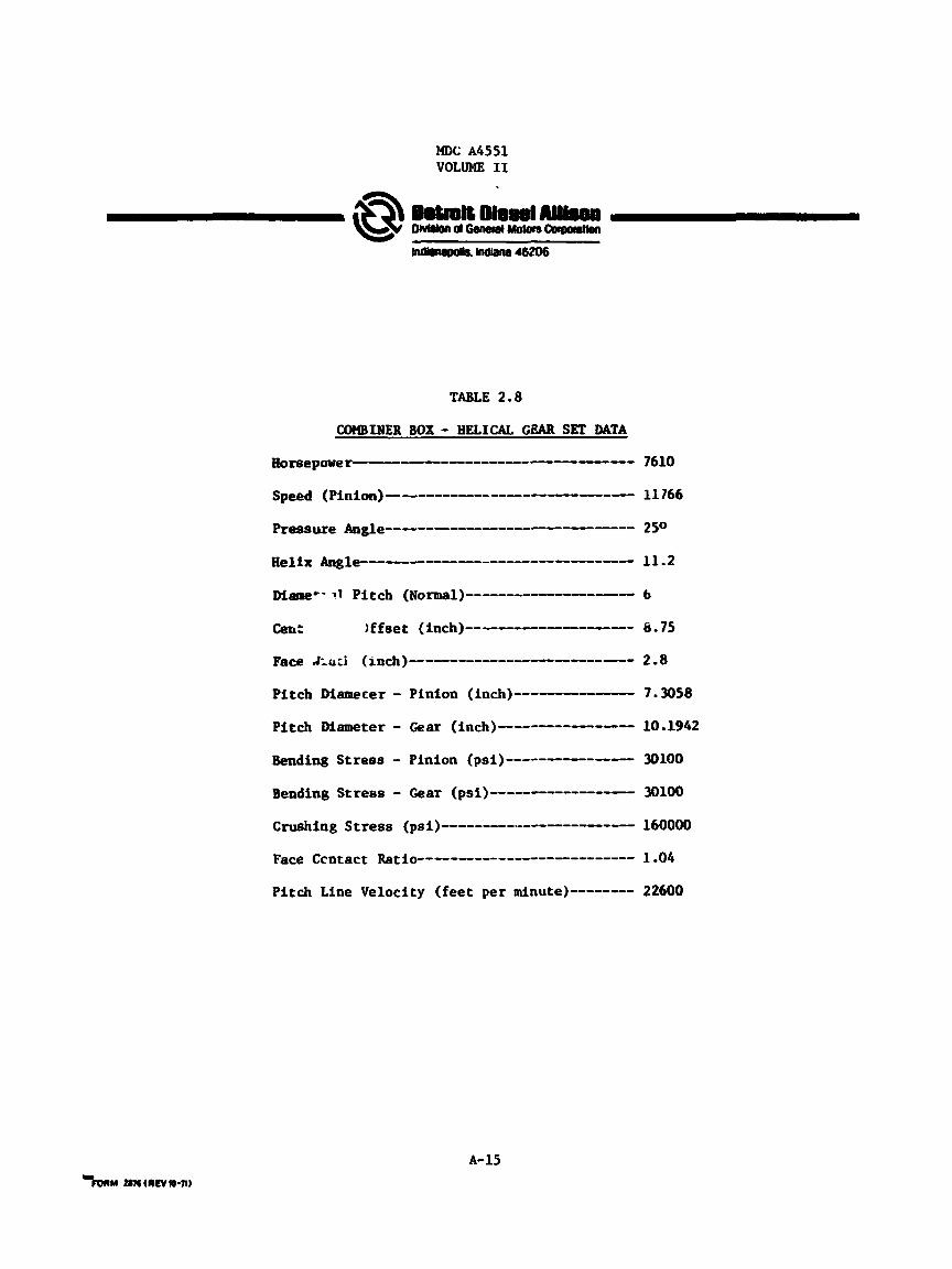
l z l i c a l Gear Set
The h e l i c a l gear set was designed t o provide i n f i n i t e l i f e at the amximan powFr levels establ ished i n Section 2.1. This is 7610 horsepower.
A DDA-developed computer a n a l y s i s w a s used t o evaluate numerous h e l i c a l gear sets and the r e su l t i ng selorction is Shawn i n Table 2.8. stress is calculated with the modified Lewis formula.
Bending
Accessory G e a r s
An accessory gear set is provided t o dr ive t h e o i l pumps f o r the combiner box. h e l i c a l gear set.
Design goals f o r t h i s set are the same as noted previously f o r t he
Gear Materials
A l l t h e RTA ctmbiner gearboxes are designed of AMs 6265 (CEVM 9310) material which is t o be carburized and ground. 64,000,000 f l i g h t hours In DDA designed gearboxes and has demonstrated its capabi l i ty qu i t e s a t i s f a c t o r i l y .
This gear material has accumulated
2.2.3 B e a r i n g s
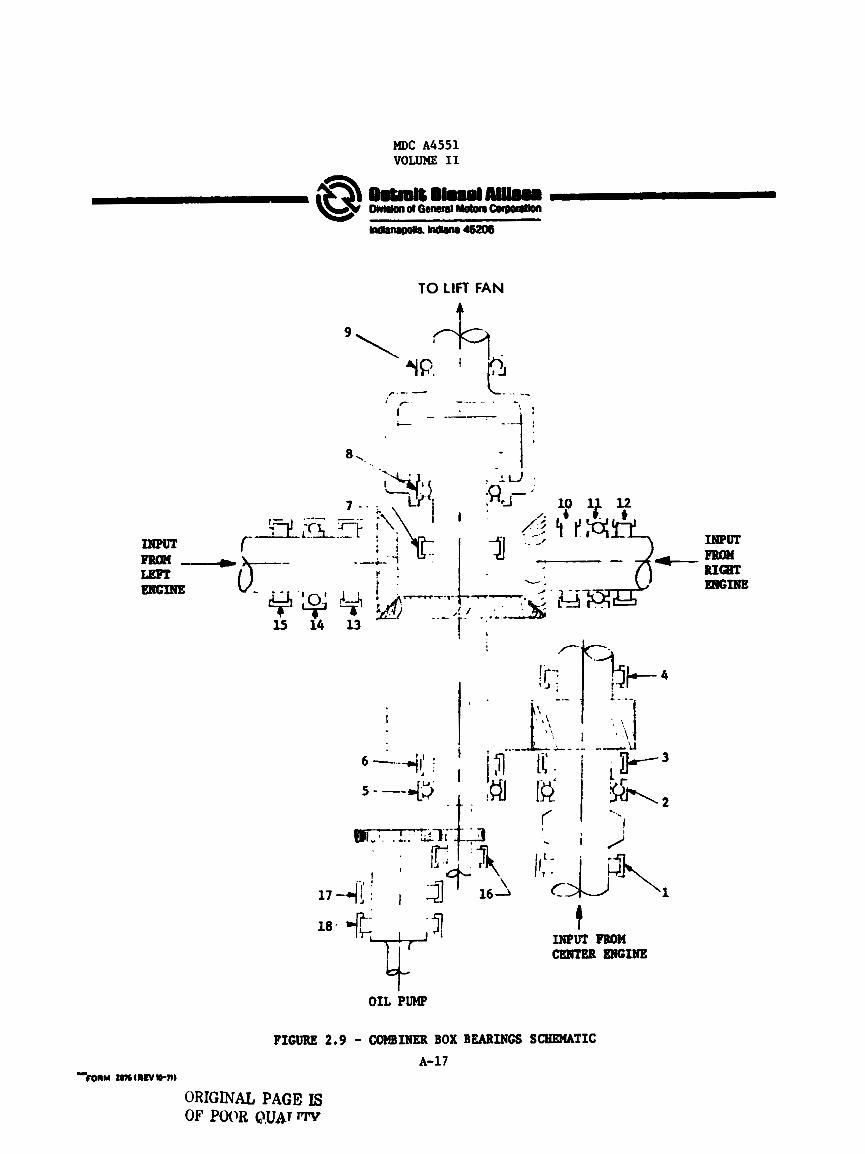
Each bearing posi t ion i n the combiner box w a s examined t o determine the maximum load f o r any of t he power conditions establ ished i n Section 2.1. The minimum bearing static capaci ty w a s then required t o be no less than the msttimum load under any cont ro i condition (including contingency). See Figure 2.9 f o r t he loca t ion o f , and numbering system f o r , the can- b iner lox bearings.
I n order t o estimate a f a t igue l i f e fo r each combiner box bearing and f o r t he systrm, a duty cycle w a s es tabl ished by which the mean bearing loads could be evaluated. high power conditions s ince the RTA is expected t o spend a l o t of time at high power.
The duty cycle was biased heavily toward the
The duty cycle used iras:
o 40% of t h e a t normal standard T.O. paver
o 30% of time a t high cru ise paver (75%) (3 engines running - lift fan off)
o 20% of time a t normal c ru i se power (40%) (3 engines running - l i f t fan o f f )
o 10% of time a t i d l e power
A- 14
M)C A 4 5 5 1 VOLUME I1
A-15

MDC A4551 VOLUME 11
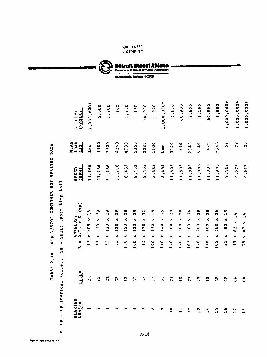
2.2.4
Bearing f a t i g i e l ife was calculated based on a modification of the AFBMA method. This procedure includes the e f f e c t of material, processing, lubricat ion, speed and misalignment to produce a more realistic estiaate of f a t i g u e l i f e f o r the a c t u a l bearing design and operating conditions.
This procedure w a s used f o r the twelve combiner box bearings that are sensitive t o transmitted load; f o r t h e other six bearings, a combined m a t e r i a l and l ub r i ca t ion fac tor of f i v e w a s used.
The r e s u l t s of this ana lys i s are shown in Table 2.10.
L i f t Fan Clutch
Function
The l i f t f a n clutch is provided t o accelerate the l i f t f an t o combiner box output s h a f t speed. cooled mult iple d i sk clutch. G i l f o r cooling and actuat ing t h e ciutch is transmitted t o the clutch by tubes passing through the combiner box from a clutch con t ro l valve mounted a t t h e rear of the canbi.net box.
This is accomplished with an 011-actuated, o i l -
The power requirements f o r the disk clutch are only those developed by the l i f t f a n while operating at minimm blade p i t ch p lus the inertia f o r t h e fan. Those are:
2 o *Fan i n e r t i a - 475 pound f t
o *Fan windage l o s s - 1000 horsepower a t f u l l speed
* E s t i m a t e s from Hamilton-Standard
A-16
MDC A4551 VOLUME I1
TO LIFT FAN
t
OIL PUMP
FIGURE 2.9 - COMBINER BOX BEARINGS SCHEMATIC A-17
-mru nrrtnCv*-n,
ORIGINAL PAGE IS OF P W R Q,U& wv
MDC A4551 VOLUME I1
MvlsM d Geneml Motors Corpontlon
Indianapolis. Indhne 46206
+ 0 0 Ln
In ..
0 0 m rl
\D \o h
rl 94
L
OI cv X
0 cv r(
X
In u7
0 0 U
L
4
0 0 In t 3
@ \o h
d 4
1
OI cv X
0 N 94
X
ln In
0 0 h
0 d N U
\o \o r-
d d
L
OI N
X
0 N 4
X
In In
0 rr) N L
4
0 cc) r- U
N cc) U
Qo L
Qo N
X
0 N N
X
0 9 r(
0 tn h
0 \o m an
c\( (? U
00 L
a0 N
X
0 N N
X
0 e r(
C 0 m 9
L
r(
0 0 m N
N m U
Qo a
N Pl
x 0 w d
x In m
0 U OI
L
-4
0 0 94 -4
N f-l U
co L
In d
x 0 pr ) d
x 0 0 4
+ 0 0 0
0 0 0
m
L
d
: e4
N (3 U
a0 L
In 9 4
X
0 J rl
X
C d rl
0 0 d - N
0 U m In
In 0 W
L
9-4 4
a0 (3
x 0 0 c.l
X
0 4 d
0 0 o\
0 9
L
0 N \o
In 0 W . rl rl
Qo (3
X
0 0 N
X
0 r(
d
0 0 9 c d
0 U (3 C J
In 0 QD L
r )
d
9 N
X
0 9
?t
In 0
4
d
0 0 r.
L
cv
0 U m rn
m 0 00 L
rl rl
00 m
X
0 0 h(
x 0 9-4 r(
0 0 OI
0 \o
0 N \o
m 0 W
m 4 4
aD (3
X
0 0 N
W
0 r(
r(
0 0 \o a d
0 U 0 N
ul 0 aD a d d
N
W
0 9 -4
X
In 0 4
+ 0 0 0
0 0 0
.L
.)
c(
a In
N m U
a L
m d
W
0 a0
x In In
+ 0 0 0
0 0 0
c
a 4
a0 h
)z fi ln
U L
U rl
X
c3 \o
X
u) (7
+ 0 0 0
0 0 0
L
I
r(
0 N
h h In
U .
U 4
X
C I rg
X
u) m
N U ln 9 h Q) 0 r(
c(
d N r(
m d
U rl
In 4
9 4
Q) c)
A-18
MDC A4551 VOLUME I1
A mechanical lock-up device is provided in the clutch mechanism t o permit transmittal of f u l l l i f t fan power a f t e r the d isk c lu tch has brought the f an t o combiner box speed. and output speed and i n h i b i t s lock-up u n t i l ro t a t iona l speeds are matched. Once speeds are matched, lock-up occurs automatically and a signal is generated t o the a i r c r a f t cont ro l system t o permit t h e l i f t f an blade angle t o be advanced in order t o develop thrus t .
The lock-up device senses d i sk clutch tnput
Clutch D i s k Materials
The l i f t fan c lu tch has been designed t o make use of a Teflon based d i s k facing material recent ly developed a t DDA f o r a General Motors i n d u s t r i a l appl icat ion. fac tory f o r use at high power loadings w h i l e running i n i n d u s t r i a l transmission o i l s . For the RTA appl icat ion, where i t is expected t h a t o i l s per MIL-L-23699 or MIL-L-7808 will be used, i t will be necessary t o run o i l compatibil i ty tests. Data avai lab le a t t h i s time does not suggest any incompatibi l i t ies between a i r c r a f t oils and t he material but t h i s will be substant ia ted by test.
It has shown i t s e l f t o be q u i t e satis-
Clutch D i s k S iz ing
The clutch d isk s i z e selected f o r the RTA design is a 7.88 inch diameter p l a t e that is avai lab le from other c lutch designs on test and i n produc- t i o n at DDA. speed which is w e l l wi thin the l imi t s of high speed clutches designed by DDA.
This s i z e y ie lds a 17,400 f t . per minute omximum rubbing
For example, the T-40 clutch ran at 18,000 ft/minute.
D i s k Clutch Details
The c lu tch as designed f o r the RTA mission is described as follows:
o Clutch plate O.D. = 7.88 in.
o 13 p la t e s - 26 f r i c t i o n surfaces
o engagement time 6 seconds
o approximately 1700 BTU t o t a l heat r e j ec t ion
A-19
MDC A4551 VOLUME I1
Oetrolt Oiesel AI I I~O~ OMdon ol General Motors C o m l b n
Indbnepolls. Indiana 46206
The previously mentioned clutch development e f f o r t a t DDA f o r an i n d u s t r i a l c lutch provides good guide l i nes fo r required clutcb coolant f low rate. This is .042 GPH/in2 vr 24 CPM for the disk c lu tch . This flcw rate is only required during clutch engagement and fo r approximately 24 seconds following clutch lock-up, a t which t i m e the coolant would be turned o f f .
Clutch pis ton pressure required t o achieve the 6-second engagement t i m e would be approximately 100 ps i maximum.
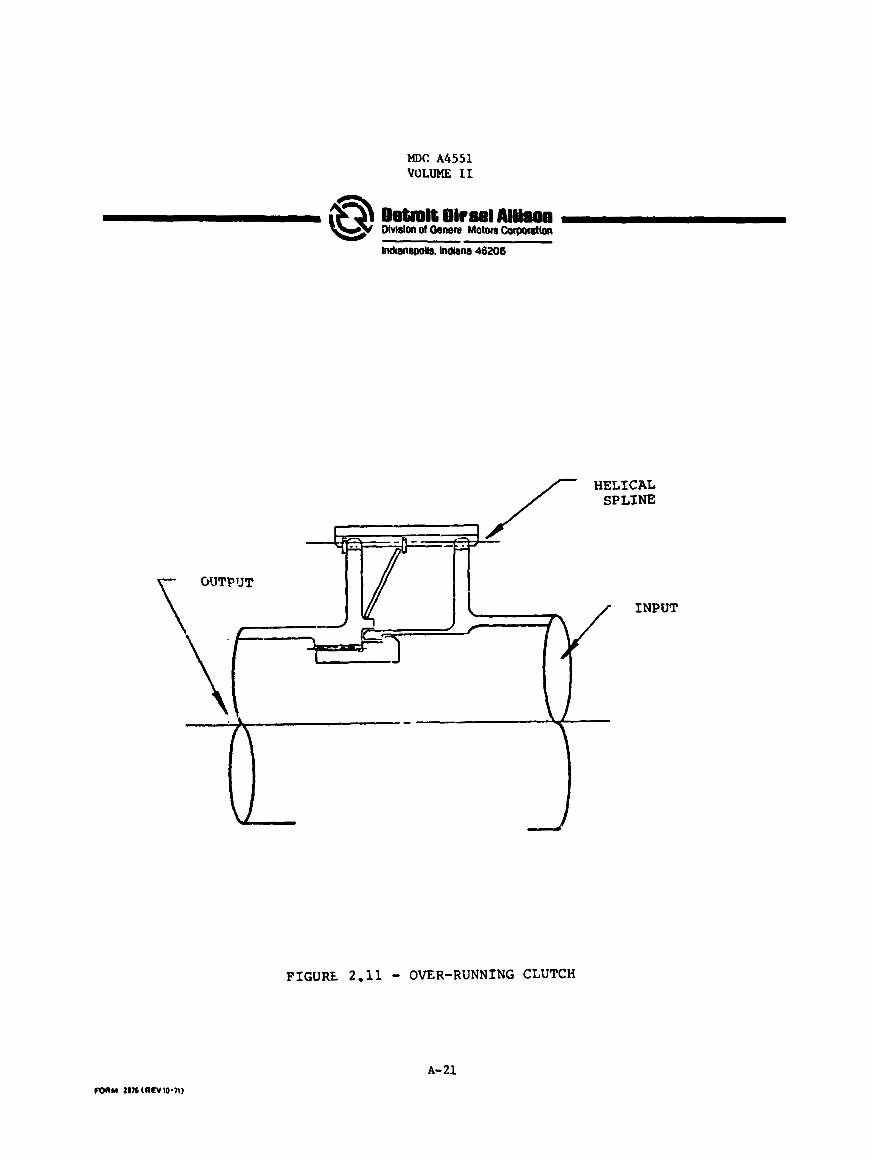
2.2.5 Over-Running Clutch
The ove r runn ing clutch w a s provided a t the center engine input t o the combiner box t o allow f o r planned o r emergency shut dawn of the center engine.
The clutch as shown i n Figure 2.11 is similar t o one designed and developed i n the T56-A-18 program. accomplished by a double set of h e l i c a l sp l ines tha t do not permit dis- engagement with a pos i t i ve torque application. When the cen te r engine is shut down and clutch torque goes negative, the h e l i c a l s p l i n e s force disengagement. While running i n the disengaged mode, r a t che t ing of the s p l i n e is inhibi ted by an a x i a l l y unbalanced centr i fugal o i l head within the over-running c lu tch . up of the center engine.
Normal power t r a n s f e r through the c lu tch fs
The clutch design w i l l permit an In-f l ight start-
The combiner box over-running clutch is the same bas i c design as would be used i n the l i f t c ru i se engine gearboxes.
2.2.6 Lubrication and Cooling System
The combiner box design contains a completely integrated lubricat ion aitd cooling system ( t h e o i l cooler would be airframe supplied and mounted). Included i n the sys tem a re t h e following:
o Low pressure pump f o r cooling and lubricat ion
0 High pressure pump fo r clutch cont ro l and gear lubricat ion
0 O i l f i l t e r
0 Pump regulators
o Pump and f i l t e r relief valves
0 Scavenge pumps
0 Clutch control valve
o O i l tank (s lght g l a s s - f i l l e r )
This system is shown schematically in Figure 2.12.
A-20
MDC A 4 5 5 1 VOLUME I1
Dotmit Dirsel Allison OMslon ol Oenen Motors C o w l o n
lndianepolk hdlana 46206
INPUT
FIGURE 2.11 - OVER-RUNNING CLUTCH
A-21

MDC A4551 VOLUME I1
Ostrolt Diesel Allirren Oivlslon ol General Motors CorWnlron
hdlanapok tatem 46206

MDC A4551 VOLUME I1
Detmit Diesel Allison OMabn ol General Motors Corpontlon
Indianapous. Indiana 46206
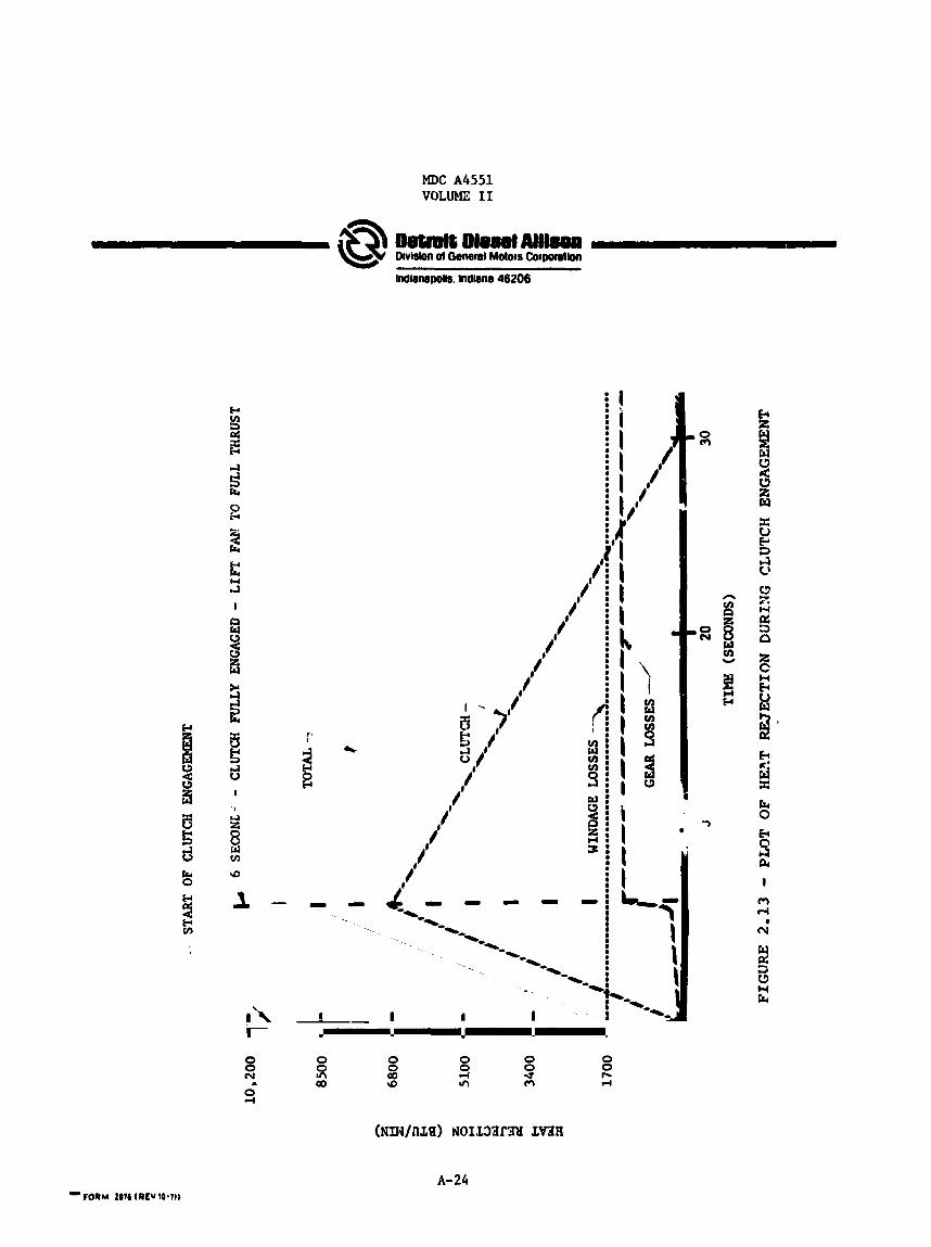
The o i l system cooling rc-quircments arc' estimated i n t h e following manner.
1 . Combiner box windage losses a t f u l l speed - 1700 B'IU/min
2. Gear and bearing s y s t e m losses ( 1 / 2 % of pa re r in each gear mesh) at T.O. power (normal) - 1400 BTU/min
3 . Gear and bearing s y s t e m losses a t contingency T.O. condition - 3560 BTU/ml:t
4. Clutch h e a t re ject ion for each engagement cycle - 1700 BTU
The gearbox cooling sys tem was designed t o handle t h e normal T.O. power heat r e j ec t ion with a 100°F o i l s y s t e m 4 1. rate of 10 GPM through the gearbox at a l l times except when the clutch is engaged. During clutch engagement and f o r 24 seconds the rea f t e r an add i t iona l 24 CPM is added t o t h e system flow t o absorb the clutch heat r e j ec t ion of 1700 BTU.
This suggests a normal f low
An approximation of t o t a l heat re ject ion a t the tfme of clutch engagement is shown i n Figure 2.13.
It is suggested tha t the oil cooler be s ized t o handle the normal T.O. paver heat r e j ec t ion of 3100 BTU/min and tha t the clutch heat r e j ec t ion be t r ea t ed as a t r ans i en t , i . e . , allow the sys tem temperatures t o rise during clutcn engagement and d i s s ipa t e t h i s heat gradually over a period of t i m e . The l a rge thermal mass of the combiner box w i l l keep the peak temperatures w i t h i r . .asonable limils.
Total oil contained i n the sump is s i x gallons. This quantity is neces- sa ry t o permit deairat ion of the o i l when the f low rate is 34 GPM.
O i l pumps for the system a re conventional spur gear pumps control!.ed by by-pass regulators and protected by pop-off type relief valves.
2 .2 .7 Case Structure and Mounts
The main combiner box case s t r u c t u r e is made up o f three rnnjpe?'!i,w c . 0 ~ 1 - ings (two covers and a diaphragm). The magnesium would be coated for corrosion protect ion. Mounting pads are cas t i n t eg ra l w i t h t h e case and could be located t o be compatible w i t h t h e l oca l airframe s t ruc tu re . The o i l tank is mounted d i r e c t l y on t h e combiner box.
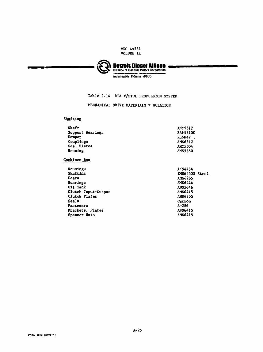
2 .2 .8 Materials
Figure 2 .14 shows the various materials t ha t have been se l ec t ed f o r c o b ponents of the combiner box.
A-23
MDC A4551 VOLUME I1
MDC A4551 VOLUME I1
Table 2.14
MECHANICAL
Shaft in&
Shaft Support Bearings Damper Couplil?gS S e a l Plates Housing
Combiner Box
Rous ings Shafting Gears Bearings Oil Tank Clutch Input-Output Clutch Plates Seals Fasteners Brackets, Plates Spanner Nuts
Detmit Diesel Allison 0)vlblcIt ol Oenerel Motors Corwretlon
IndianaDolls. lndiene 46206
RTA V/STOL PROPULSION SYSTEM
DRIVE MATERLALS T B U U T I O N
AMT5512 SAE 52100 Rubber . AMs6512 AMZ5504 AMs5350
Ais4434 lNS64500 Steel AM66265 AMs6444 AMs5646 AMs6415 M 6 3 5 5 Carbon
AMs6415 AMs64 15
~-286
A-25
NDC A6551 VOLUME I1
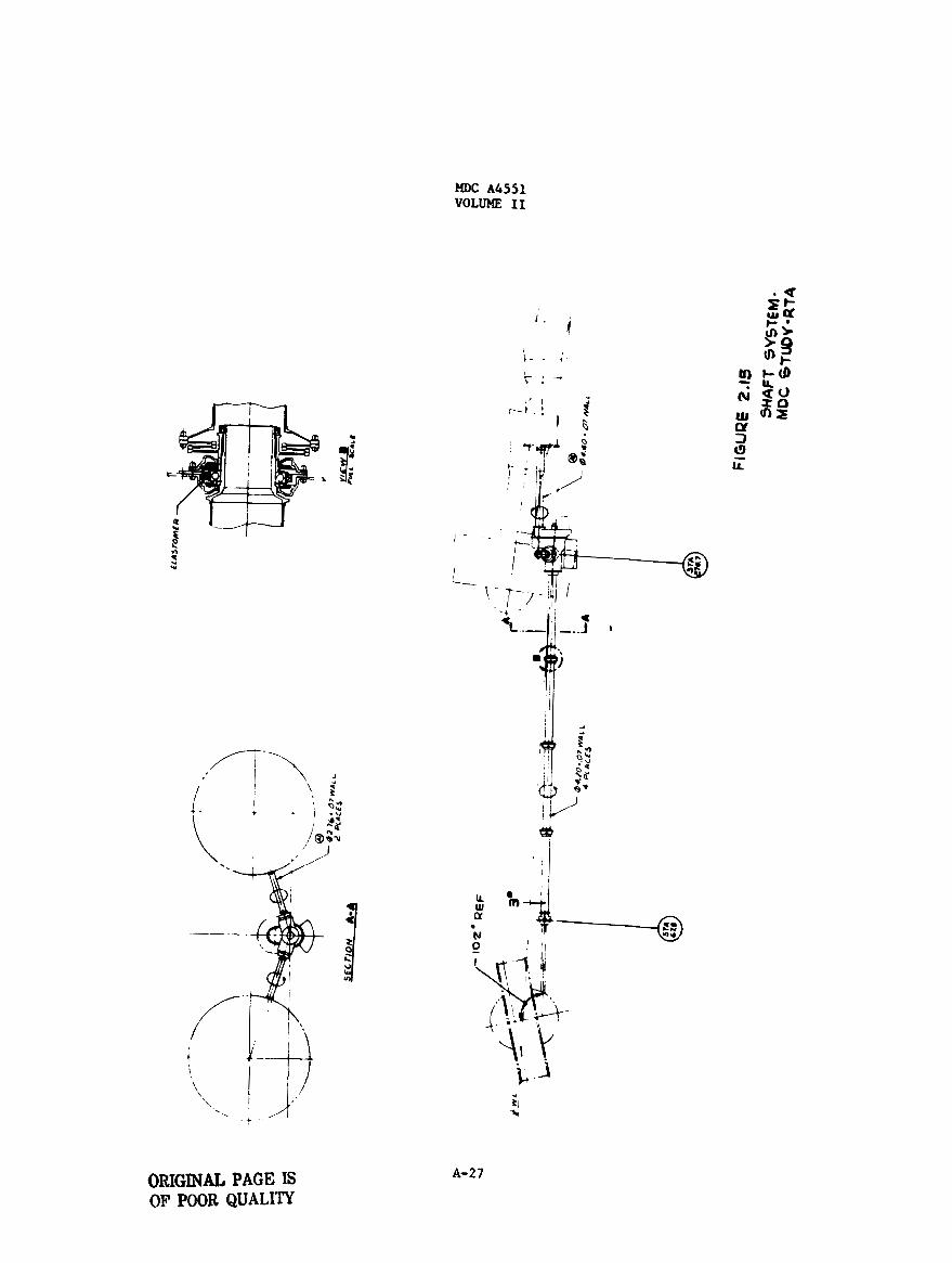
2.3 Shaf t ing
The shaf t ing for the RTA propulsion sys tem was designed t o m e e t t he speed and load requirements es tabl ished i n Section 2.1. Subcr i t ica l design points were selected t o minimize development e f f o r t and r i sk . (The weight increase fa- 'I is approach is s l igh t . ) Figure 2.15 is t he RTA shaft system.
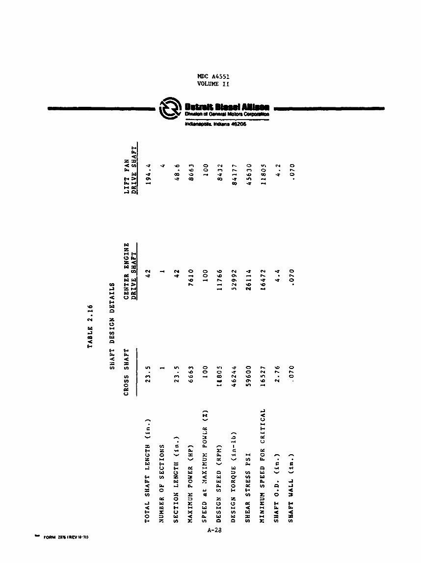
S h a f t design d e t a i l s are shown i n Table ?.16.
C r i t i c a l speeds were calculated f o r each sha f t assuming simple supports. The l i f t f an s h a f t L;$ evaluated f o r a number of d i f f e ren t segments and i t support bearings) w a s achieved with four sec t ions of sh. 'ting. be noted that t h e l i f t f an s h a f t discussed herein does not include the por- t i o n of t he shaft that passes through the l i f t f an a i r stream stat .
as found that the ninirmrm weight f o r t he shaft(inc1uding intermediate It should
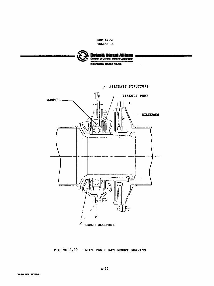
A support bearing and coupling assembly was designed f o r use a t each inter- m e d i a t e point of support f o r the l f f t f an shaf t . See Figure 2.17. The support bearings nre lubricated by grease t h a t is c i rcu la ted through t h e bearing by a bui l t - in viscous pump. Bearing loads are law f o r the shafting and there are not any rubbing grease seals t o wear out , therefore t h i s type of assembly is expected t o give a long trouble-free l i f e . Routine main- tenance would not be required of t h i s asse&ly.
The coupling incorporates a diaphragm t o alluu f o r s h a f t angular misalign- m e n t and l imited axial displacement. can be var ied t o account f o r misalignment. Airframe a t t ach points f o r the l i f t f a n support bearings would not requi re prec ise machining tolerances, r a t h e r i t is planned that the supports would be shimmed t o f i t at i n s t a l l a t i o n .
The number of diaphragms 1n the coupling
A reasonable cont ro l on the combiner gearbox t o l i f t fan dis tance would be expected and the tolerance f o r t h i s would be taken up i n t h e end fittings a t assembly.
Each Lf t fan sha f t coupling assembly is estimated t o weigh 12 pouds .
Shafting materials are shown i n Figure 2 .14 .
A-26
MDC A4551 VOLUME I1
, - - - .
A-27 ORIGINAL PAGE IS OF POOR QUALIlr
MDC A4551 VOLUME I1
n
e U v
X cc W 2 w IJ
cc a < X tn
cl c b 0 e
VI z 0
e u w tn a 0
d w r9 X 3 7,
Y
n a X W
d w 5 0 a r 3
X U E
E
n N Y
cz La 5 0 a
L1 cd
0 w w a tn
n r n [I?; W
11 w w n tn
z 2 v) w P
n 3 4
I C *
W
w 3 0. d 0 b
z 2 tn w P
I4 v) a tn v) w d w v)
a d w E tn
IJ U 0
e d u M 0 I+r
P w w 0. tn
X 3 E
z E
Y
Y
Y
W
n
2 * W
P
0
k a d z tn
M)C A4551 VOLUME I1
I A I RC RA FT S T BU CTURE
DAWER - VISCOUS PUMP r-
i 2 ! ,’ LGREASE RESERVOIR
FIGURE 2.17 - LIFT FAN SHAFT MOUNT BEARING
A-29
MDC A4551 VOLUME I1
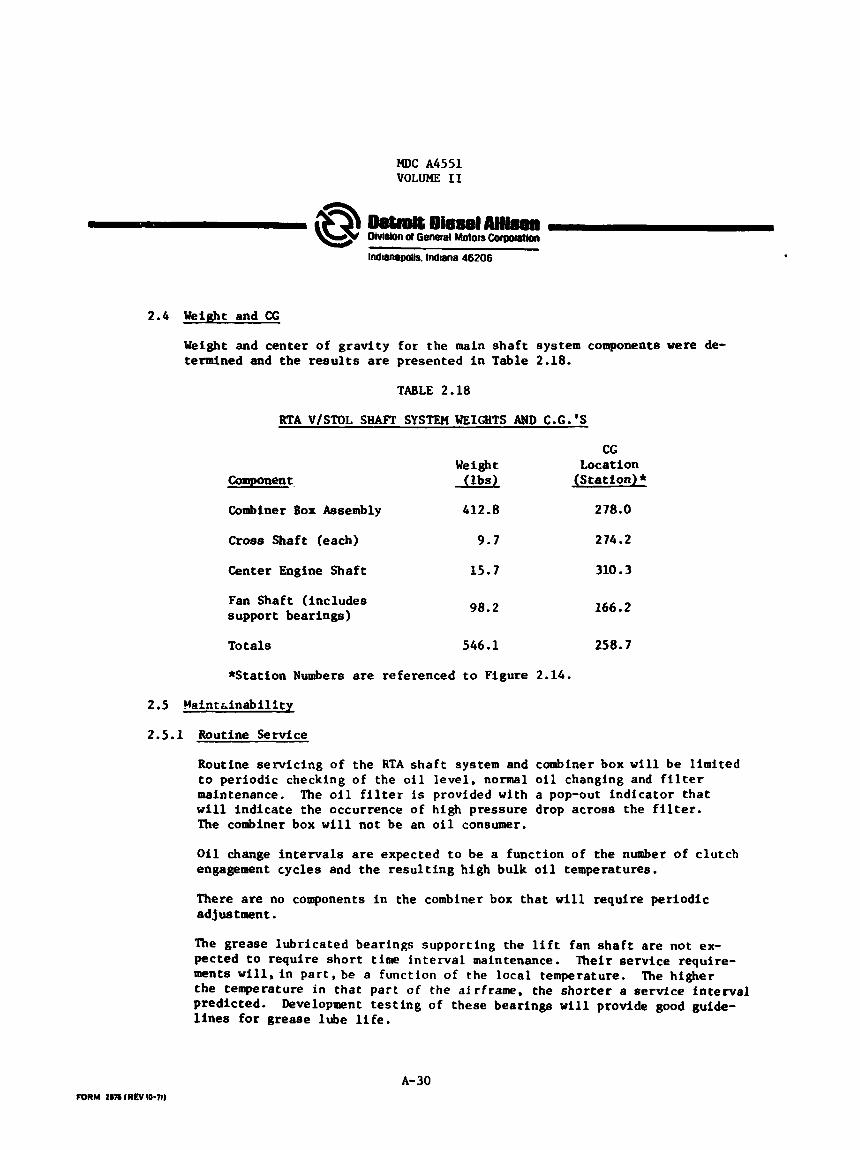
2.4 Weifit and CG
Weight and center of grav i ty for the main s h a f t system components were de- termined and the r e s u l t s are presented i n Table 2.18.
TABLE 2.18
RTA V/STOL SHAFT =STEM WEIGHTS AND C.G.'S
CG Weight Location
(lbs) (Station)*
Combiner Box Assembly 412.8 278.0
Cross Shaft (each) 9.7 274.2
Center Engine Shaft 15.7 310.3
Fan Shaft ( includes support bearings) 98.2 166.2
Totals 546.1 258.7
*Station Numbers are referenced to Figure 2.14.
2.5 Maint;inability
2.5.1 Routine Service
Routine serv ic ing of the RTA s h a f t system and combiner box w i l l be l i m i t e d t o periodic checking of the oil l eve l , normal oil changing and f i l t e r maintenance. The oil f i l t e r is provided with a pop-out indicator t h a t w i l l i nd ica t e the occurrence of high pressure drop across the f i l t e r . The combiner box w i l l not be an o i l consumer.
O i l change intervals are expected t o be a function of the number of c lutch engagement cycles and the r e s u l t i n g high bulk o i l temperatures.
There are no components i n the combiner box t h a t w i l l require per iodic adjustment.
The grease lubricated bearings supporting the l i f t fan s h a f t are not ex- pected t o require sho r t time in t e rva l maintenance. ments w i l l , i n p a r t , be a function of t h e local temperature. the temperature i n t ha t par t of t h e afrframe, t h e s h o r t e r a service in t e rva l predicted. l i n e s f o r grease lube l i f e .
Their service require- The higher
Development t e s t i n g of these bearings w i l l provide good guide-
A-30
MDC A4551 VOLUME 11
2.5.2 Overhaul Requirements
In a production program, the combiner box would be subject t o on-condition repa i r . This same approach. for a minimum cost program, would generally apply t o the RTA program. ceive routine boroscope inspections with some disassembly being required for fu r the r inspection andfor repa i rs .
I t is expected t h a t the combiner box would re-
Combiner box disassembly and r epa i r w i l l require a l imfted number of spec ia l t o o l s and technicians experienced i n a i r c r a f t transmission r e p a i r pro- cedures.
Combiner box components such as the disk clutch, over-running c lu tch oil pump, regulators and c lu tch con t ro l valve can be removed vi thout a complete disassembly.
A-31