QUICK SWAP PARTS OPERATION AND MAINTENANCE ENGLISH...
44
QUICKSWAP For serial number(s): QS-561 QS-562 QS-566 QS-567 QS-568 QS-569 QS-570 QS-571 QS-572
Transcript of QUICK SWAP PARTS OPERATION AND MAINTENANCE ENGLISH...

QUICKSWAP
For serial number(s): QS-561 QS-562 QS-566 QS-567 QS-568 QS-569 QS-570 QS-571 QS-572


Table of Contents
1. Technical Specifications and Ratings............................................................................................ 1 1.1. General Specifications ................................................................................................................. 1 1.2. Hydraulic System (option) ........................................................................................................... 1 1.3. Axle-Lift Ratings............................................................................................................................ 1 1.4. Winch Ratings (option)................................................................................................................. 1 1.5. Quick Swap Dimension ................................................................................................................ 2
1.5.1. Quick Swap Under-lift Dimensions .......................................................................................... 2 1.5.2. Axle-Lift Dimensions ................................................................................................................ 2
1.6. Installation ..................................................................................................................................... 2 2. Description of Components ............................................................................................................ 3
2.1. Quick Swap Assembly.................................................................................................................. 3 2.2. Boom .............................................................................................................................................. 4
2.2.1. Quick-Swap Under-lift Boom and Parts List Diagram.............................................................. 4 2.2.2. Boom Cylinder ......................................................................................................................... 5
2.3. Electrical kit ................................................................................................................................... 5 2.4. Roller Guide................................................................................................................................... 6 2.5. Jack Leg......................................................................................................................................... 6 2.6. Tool Box......................................................................................................................................... 7 2.7. Axle-Lift.......................................................................................................................................... 8
2.7.1. Axle Lift and Roller Guide ........................................................................................................ 8 2.7.2. Axle Lift and Parts List Diagram .............................................................................................. 9 2.7.3. Heavy Duty Axle-Lift Horizontal Section and Parts List......................................................... 10 2.7.4. Axle-Lift Extension Cylinder................................................................................................... 11 2.7.5. Axle-Lift Fold Up Cylinder ...................................................................................................... 12
2.8. Quick Swap Elevation Cylinder ................................................................................................. 13 2.9. Winches ....................................................................................................................................... 14
2.9.1. Air Clutch Solenoid (12V) for Ramsey 25000 Winches with Parts List ................................. 15 2.9.2. (F-V) 1 Function assembled gm plug .................................................................................... 16
2.10. Caution Valve .............................................................................................................................. 17 2.10.1. Caution Valve and Parts List ................................................................................................. 17
2.11. Control Equipment...................................................................................................................... 19 2.11.1. Hydraulic Diagrams ............................................................................................................... 19 2.11.2. Electrical Diagrams................................................................................................................ 20
3. Operation......................................................................................................................................... 21 3.1. Lifting Precautions...................................................................................................................... 21 3.2. Procedures for Operating the Axle-Lift..................................................................................... 23 3.3. Procedures for Operating Winches........................................................................................... 24 3.4. Mounting a Quick Swap to a Carrier Chassis .......................................................................... 25
4. Maintenance .................................................................................................................................... 26 4.1. General maintenance of parts ................................................................................................... 26 4.2. Lubrication Charts ...................................................................................................................... 27
4.2.1. Lubrication Interval ................................................................................................................ 27 4.3. Hydraulic Pressure Adjustment ................................................................................................ 28 4.4. Security Relief Valve; part number 8684038 ............................................................................ 29 4.5. Procedure to adjust a pressure cartridge CBCG-LJN............................................................. 30 4.6. Caution Valve Adjustment ......................................................................................................... 31 4.7. Component Disassembly ........................................................................................................... 32
4.7.1. Axle-Lift Disassembly ............................................................................................................ 32 4.7.2. Drawing for Axle-Lift Disassembly......................................................................................... 33
5. Troubleshooting ............................................................................................................................. 34 5.1. Winches ....................................................................................................................................... 34
6. Supplier Information....................................................................................................................... 35 7. Maintenance Records..................................................................................................................... 36

8. Warranty Offered by NRC Industries ............................................................................................ 37 9. Appendix A...................................................................................................................................... 38
9.1. Notes ............................................................................................................................................ 38 9.2. Operator’s Logbook.................................................................................................................... 39

Parts, Operation and Maintenance Manual
- 1 -
1. Technical Specifications and Ratings
1.1. General Specifications General Specifications Quick Swap Under-Lift
Minimum Wheelbase 250" Recommended Wheelbase 265" to 275" Weight (without winch) 5,500 lbs. Power elevation S Power extension S Power tilt S Removable S S=Standard
1.2. Hydraulic System (option)
Hydraulic System Quick Swap Under-Lift
Direct Mount Hydraulic Pump Simple, 17 GPM Working Hydraulic Pressure 2800 PSI.
1.3. Axle-Lift Ratings Axle-Lift Heavy Duty
Axle-Lift Capacity (Retracted) 35,000 lbs.
Axle-Lift Capacity (Extended) 15,000 lbs.
Reach Fully Retracted 70"
Reach Fully Extended 109"
1.4. Winch Ratings (option) Winches and Cables DP 20,000 lbs. Ramsey 25,000 lbs.
Winch Capacity 20,000 lbs. 25,000 lbs.
Winch Type Planetary Worm Gear
Wire Rope 5/8” X 200’ 5/8” X 200’
NOTE: THE WINCH AND UNDER-LIFT RATINGS ARE BASED ON THE STRUCTURAL CAPACITY OF STATIC STEEL.

Parts, Operation and Maintenance Manual
- 2 -
1.5. Quick Swap Dimension 1.5.1. Quick Swap Under-lift Dimensions
1.5.2. Axle-Lift Dimensions
1.6. Installation For the installation on a chassis, a DVD recorded at the factory is available on request

Parts, Operation and Maintenance Manual
- 3 -
2. Description of Components
2.1. Quick Swap Assembly
NRC Code: 8656015 ITEM QTY NRC CODE NAME DESCRIPTION 1 2 0517103 BIG SPRING - 2 2 0540232 ROLLED SPRING PIN 3/16" x 1 1/2" LG. 3 2 0540270 ROLLED SPRING PIN 3/8" x 3" LG. 4 4 0554200 EXTERNAL SNAP RING Ø2" 5 2 0612423 CAP SCREW 1/4-20UNC x 3/4" (STAINLESS) 6 20 0612733 CAP SCREW 5/16-18UNC x 1" (S/S) 7 4 0613631 HEX CAP SCREW 1/2-13UNC X 1 1/4" 8 12 0614241 HEX CAP SCREW 5/8-11UNC X 1 1/2" 9 4 0614552 CAP SCREW 3/4-10UNC X 2"
10 20 0822129 HEX NYLON NUT 5/16-18UNC S/S 11 4 0828111 HEX NUT 3/4-10UNC 12 2 0911215 SPRING LOCK WASHER 1/4" (STAINLESS) 13 40 0911305 FLAT WASHER 5/16" S/S 14 4 0911611 SPRING LOCK WASHER 1/2" 15 4 0911901 FLAT WASHER 3/4" 16 12 0912001 FLAT WASHER 7/8" 17 2 1314001 80" HALFT FENDER 68.843" x 20.553" x 25" 18 6 1931203 ZERT STRAIGHT 3/16 PRESS-FIT 19 2 8133041 LATCH PIN - 20 1 8133129 PIN OF BOOM - 21 1 8133130 AXLE-LIFT/BOOM PIN - 22 2 8165085 QUICK-SWAP SUPPORT - 23 1 8181617 CONNECTOR CAP - 24 1 8183016 VALVE CONTROL COVER - 25 1 8220017 QUICK-SWAP ASSEMBLY QSS 26 1 8221001 RIGHT FENDER SUPPORT - 27 1 8221006 LEFT FENDER SUPPORT - 28 1 8222004 FRONT QUICK-SWAP ANCHOR - 29 2 8270007 PIN - 30 2 8270019 CYLINDER HEAD PIN - 31 1 8650020 AXLE-LIFT QSS 32 1 8656003 BOOM ASSEMBLY QSS 33 1 8656017 ROLLER GUIDE QSS 34 2 8656029 JACK LEG ASSEMBLY QSS QSE 35 1 8681021 ELECTRICAL KIT QSS 36 2 8695045 CYLINDER Ø3 1/2" x 36 7/8"

Parts, Operation and Maintenance Manual
- 4 -
2.2. Boom
2.2.1. Quick-Swap Under-lift Boom and Parts List Diagram
NRC Code: 86560003
Item Qty Code Name 1 1 8230032 Boom large section 2 1 8230033 Boom small section 3 1 8695044 Cylinder 4 1 8133070 Pin 5 1 8133003 Pin 7 4 0553150 Internal snap ring 1-1/2"
Parts, Operation and Maintenance Manual
- 5 -
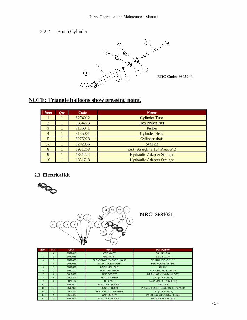
2.2.2. Boom Cylinder
NOTE: Triangle balloons show greasing point.
Item Qty Code Name 1 1 8274012 Cylinder Tube 2 1 0834223 Hex Nylon Nut 3 1 8136041 Piston 4 1 8135001 Cylinder Head 5 1 8275028 Cylinder shaft
6-7 1 1202036 Seal kit 8 1 1931203 Zert (Straight 3/16” Press-Fit) 9 1 1831224 Hydraulic Adapter Straight
10 1 1831718 Hydraulic Adapter Straight
2.3. Electrical kit
NRC Code: 8695044
Item Qty Code Name Description1 6 2552019 GROMMET Ø4 1/4" x 7/8"2 2 2552035 GROMMET Ø2 1/2" x 7/8"3 2 2552069 CLEARANCE MARKER LIGHT FEU ROUGE, Ø2 1/2" 4 4 2552065 STOP & TURN LIGHT FEU ROUGE, Ø4 1/4"5 2 2552008 BACK-UP LIGHT Ø4 1/4"6 1 2540101 ELECTRIC PLUG 4 POLES; FIL 12-PLUS7 4 0612433 CAP SCREW 1/4-20UNC x 1" (STAINLESS)8 6 0911205 FLAT WASHER 1/4" (STAINLESS)9 4 0821112 HEX NUT 1/4-20UNC (STAINLESS)
10 1 2540001 ELECTRIC SOCKET 4-POLES11 1 2540901 SOCKET BOOT PRISE 7 POLES; CAOUTCHOUC NOIR12 2 0911215 SPRING LOCK WASHER 1/4" (STAINLESS)13 2 0612423 CAP SCREW 1/4-20UNC x 3/4" (STAINLESS)14 2 2540004 ELECTRIC SOCKET 7-POLES PLASTIQUE
NRC: 8681021

Parts, Operation and Maintenance Manual
- 6 -
2.4. Roller Guide
2.5. Jack Leg
Item Qty NRC code Name Description1 1 8250001 ROLLER GUIDE -2 4 0614261 HEX CAP SCREW 5/8-11UNC X 2"3 8 0911801 FLAT WASHER 5/8"4 4 0827121 HEX NYLON NUT 5/8-11UNC5 6 1931203 ZERT STRAIGHT 3/16" PRESS-FIT
Item Qty Code Name Description1 1 8221004 INTERMEDIATE JACK LEG -2 1 1931203 ZERT STRAIGHT 3/16 PRESS-FIT3 1 8133041 LATCH PIN ø1" x 4 3/4"4 1 0540232 ROLLED SPRING PIN 3/16"DIA x 1 1/2" LG.5 1 0540270 ROLLED SPRING PIN 3/8"DIA x 3" LG.6 1 0517103 BIG SPRING -7 1 8236038 PARKING JACK LEG -
NRC: 8656028
NRC: 8656029
Parts, Operation and Maintenance Manual
- 7 -
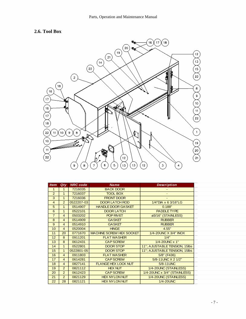
2.6. Tool Box
Item Qty NRC code Name Description1 1 7216035 BACK DOOR -2 1 7216037 TOOL BOX -3 1 7216036 FRONT DOOR -4 2 0522207-03 DOOR LATCH ROD 1/4"DIA x 6 3/16"LG5 1 0514907 HANDLE DOOR GASKET 0.188"6 1 0522101 DOOR LATCH PADDLE TYPE7 4 0503202 POP RIVET ø3/16" (STAINLESS)8 4 0514909 GASKET RUBBER9 4 0514910 GASKET RUBBER10 4 0520004 HINGE 4.55"11 20 0771670 MACHINE SCREW HEX SOCKET 1/4-20UNC X 3/4" INOX12 8 0911201 FLAT WASHER 1/4"13 8 0612431 CAP SCREW 1/4-20UNC x 1"14 1 0522801 DOOR STOP 11"; AJUSTABLE TENSION, 15lbs15 1 0522801-05 DOOR STOP 11"; AJUSTABLE TENSION, 15lbs16 4 0911803 FLAT WASHER 5/8" (F436)17 4 0614281 CAP SCREW 5/8-11UNC X 2 1/2"18 4 0827141 FLANGE HEX LOCK NUT 5/8-11UNC19 2 0821112 HEX NUT 1/4-20UNC (STAINLESS)20 2 0612423 CAP SCREW 1/4-20UNC x 3/4" (STAINLESS)21 2 0821129 HEX NYLON NUT 1/4-20UNC (STAINLESS)22 28 0821121 HEX NYLON NUT 1/4-20UNC

Parts, Operation and Maintenance Manual
- 8 -
2.7. Axle-Lift
2.7.1. Axle Lift and Roller Guide
Item Qty Code Name
1 1 8650020 Axle-Lift 2 1 8250001 Roller Guide 3 4 0614401 Cap Screw 5/8"-11UNC x 7″ 4 4 0827121 Nylon Hex Nut 5/8"-11UNC 5 6 1931203 Grease Nipple (Zert) Straight 3/16" Press-Fit
NRC Code: 8650021

Parts, Operation and Maintenance Manual
- 9 -
2.7.2. Axle Lift and Parts List Diagram
Item Qty Code Name
1 1 8213024 Axle-Lift Vertical Section 2 1 8650010 Horizontal Section 3 2 8690023 Roller and Bushing Assembly 4 1 8695009 Cylinder 5 2 1931203 Zert (Straight 3/16” Press-Fit) 6 1 8270001 Axle-Lift Pin for Lever Cylinder 7 1 8270002 Axle-Lift Hinge Pin 8 1 8133058 Pin 9 1 0613031 Cap Screw
10 1 0613051 Cap Screw 11 1 0613091 Cap Screw 12 2 0823111 Hex Nut 13 3 0911411 Spring Lock Washer 14 2 0911401 Flat Washer 15 2 0612421 Cap Screw 16 2 0911211 Spring Lock Washer 17 1 8154188 Hydraulic Hose Guide
NRC Code: 8650020

Parts, Operation and Maintenance Manual
- 10 -
2.7.3. Heavy Duty Axle-Lift Horizontal Section and Parts List
Item Qty Code Name
1 1 8213002 Axle-Lift Large Section 2 1 8213003 Axle-Lift Medium Section 3 1 8213004 Axle-Lift Small Section 4 1 8213005 T-Bar 5 1 8695008 Extension Cylinder 6 1 8185073 Teflon Pad 8 1 8185072 Teflon Pad 9 2 8101231 Teflon Pad Anchor 10 1 8188001 T-Bar Pin Bolt 11 1 8133158 T-Bar Pin Nut 12 1 8145009 Brass Bushing 13 1 0623600 Custom Cylindrical Bolt 14 3 0633610 Hex Socket Cap Screw 15 8 0613621 Hex Bolt 16 8 0911611 Spring Lock Washer 17 8 1931203 Zert (Straight 3/16" Press-Fit) 18 1 8133060 Pin 19 1 8133061 Pin 20 2 8185014 Teflon Pad 21 1 8101418 Spacer 22 2 8101419 Spacer 23 2 0554125 Exterior Snap Ring 24 2 0553125 Interior Snap Ring 25 2 8168029 Stopper
NRC Code: 8650010

Parts, Operation and Maintenance Manual
- 11 -
2.7.4. Axle-Lift Extension Cylinder
Item Qty Code Name 1 1 8274009 Cylinder Tube 2 1 0830225 Hex Nylon Nut 3 1 8136021 Piston 4 1 8135021 Cylinder Head 5 1 8275008 Cylinder shaft
6-7 1 1202007 Seal kit 8 1 1931203 Zert (Straight 3/16” Press-Fit) 9 1 1821410 Hydraulic Adapter Straight
NRC Code: 8695008

Parts, Operation and Maintenance Manual
- 12 -
2.7.5. Axle-Lift Fold Up Cylinder
Item Qty Code Name 1 1 8274010 Cylinder Tube 2 1 0829220 Hex Nylon Nut 3 1 8136014 Piston 4 1 8135013 Cylinder Head 5 1 8275009 Cylinder shaft
6-7 1 1202004 Seal kit 8 2 1931203 Zert (Straight 3/16” Press-Fit)
NRC Code: 8695009
Parts, Operation and Maintenance Manual
- 13 -
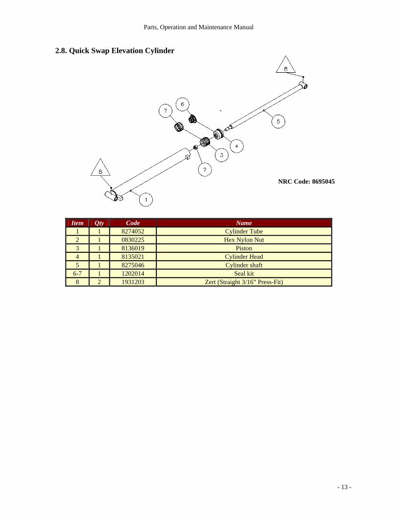
2.8. Quick Swap Elevation Cylinder
Item Qty Code Name 1 1 8274052 Cylinder Tube 2 1 0830225 Hex Nylon Nut 3 1 8136019 Piston 4 1 8135021 Cylinder Head 5 1 8275046 Cylinder shaft
6-7 1 1202014 Seal kit 8 2 1931203 Zert (Straight 3/16” Press-Fit)
NRC Code: 8695045

Parts, Operation and Maintenance Manual
- 14 -
2.9. Winches DP 20BHX4X6G-004 (NRC code: 3420027) Specifications: Weight 355 lbs. Air Clutch Release
DP 20,000 lbs. Winch Performance
Layer ∅ 5/8" Cable Cap. Line Pull Line Speed (fpm)
1 30 20,000 lbs. 28 2 67 16,600 lbs. 34 3 110 14,200 lbs. 40 4 159 12,400 lbs. 46 5 214 11,000 lbs. 52
The rated line pulls are for the winch only. Consult the wire rope manufacturer for wire rope ratings. Line speed is based on 20 GPM Flow Rate at 2550 PSI. max. Cable capacities are in accordance with SAE J706, with the exception of the last wrap. (actual capacities are usually up to 10% greater than those shown.)
Source: DP Manufacturing, Inc.
Ramsey 120564-G (F.O.R.S) H800-R (NRC code: 3420033) Specifications: Gear Reduction 40:1 Shipping Weight 330 lbs.
Ramsey H-800 Winch Performance
Layer ∅ 5/8" Cable Cap. Line Pull Line Speed (fpm)
1 35 ft. 25,000 lbs. 18 2 75 ft. 20,800 lbs. 22 3 125 ft. 17,900 lbs. 26 4 180 ft. 15,600 lbs. 29 5 240 ft. 13,900 lbs. 33
The rated line pulls are for the winch only. Consult the wire rope manufacturer for wire rope ratings. Line speed is based on 30 GPM Flow Rate. Cable capacities are in accordance with SAE J706, with the exception of the last wrap. (Actual capacities are usually up to 10% greater than those shown.) Source: Ramsey Winch Company Parts and Operators Manual.

Parts, Operation and Maintenance Manual
- 15 -
2.9.1. Air Clutch Solenoid (12V) for Ramsey 25000 Winches with Parts List
Item Qty Code Name Description 1 4 0727425 MACHINE SCREW SQUARE SOCKET #8-32UNC X 3/8" 2 1 2110400-01 PNEUMATIC HOSE 4 PLASTIQUE NOIR/SAE J844D TYPE-3B3 3 2221404-PC PNEUMATIC ADAPTER 90D RPC-N2-T4 4 1 2251404-PC PNEUMATIC ADAPTER TEE RPT-T4-N2-T4 5 2 2329001 BREATHER VENT Ø/8"-27 NPT 6 1 2502903-X01 CONDUIT INSTALLED BY HOT Ø1/2" x 1" LG 7 1 2512001 SOLENOID SWITCH 153JJ2XGM-12VDC 8 1 2512002 SOLENOID SWITCH 154JJ2XGM-12VDC 9 1 2542011 RING TERMINAL FIL 12-10; VIS 8-10
10 1 8101246 SOLENOID BRACKET - 11 1 8681008 (F-V) 1 FUNCTION ASSEMBLED GM PLUG -
NRC CODE: 8680015

Parts, Operation and Maintenance Manual
- 16 -
2.9.2. (F-V) 1 Function assembled gm plug
Item Qty Code Name Description 1 1 2543301 OEM TERMINAL FEMALE 20-18 GA 2 1 2543401 CABLE SEAL 18-20 GA ; VERT 3 1 2543701 CONNECTOR 1 CAVITÉ, FEMELLE
NRC CODE: 8681008

Parts, Operation and Maintenance Manual
- 17 -
2.10. Caution Valve
2.10.1. Caution Valve and Parts List
Item Qty Code Name Description 1 1 3460406 CUSHING VALVE 30 GPM 2 2 1831232 HYD ADAPTER STRAIGHT RHD-N8-J6 3 2 0612811 CAP SCREW 5/16-18UNC x 3" 4 2 0822111 HEX NUT 5/16-18UNC 5 2 0911311 SPRING LOCK WASHER 5/16" 6 2 8189016 MODIFIED HYD ADAPTER STRAIGHT -
NRC CODE: 8684014

Parts, Operation and Maintenance Manual
- 18 -
Hydraulic Valve
Item Qty Code Name 1 1 3460008-95 5 Spools For DP Winch and Remote
Control 6 Buttons 1-1 1 3460006 5 Spools Valve 1-2 2 3463023 Cap 1-3 5 3461006 Lever Pivot Box 1-4 3 3463024 Pneumatic Pilot 2 8 1834128 Hyd Adaptor Straight 3 2 1834130 Hyd Adapter Straight 4 2 1824136 Hyd Adapter 90D 5 2 1852406 Hyd Adapter Tee 6 3 0612821 Cap Screw 7 3 0822121 Hex Nylon Nut 8 6 2231202 Pneumatic Adapter Straight 9 6 2512001 Solenoid Switch
10 6 2221404-PC Pneumatic 90D Fitting N/S 5 3461008-91 Control Lever N/S 5 3467001 Bellows
N/S: Not Shown

Parts, Operation and Maintenance Manual
- 19 -
2.11. Control Equipment
2.11.1. Hydraulic Diagrams

Parts, Operation and Maintenance Manual
- 20 -
Parts, Operation and M
aintenance Manual
2.11.2. Electrical Diagrams

Parts, Operation and Maintenance Manual
- 21 -
! !
3. Operation WARNING Before each use of the Quick-Swap, the operator must check if main hydraulic
hoses, 7 and 4 electric prongs plugs, are properly plugged and the fifth wheel correctly locked.
WARNING: To prevent damage to the P.T.O. or transmission, we highly recommend to install
a relief valve with bypass directly on the pump. This valve will protect the P.T.O. and transmission if somebody engages the P.T.O. while the hydraulic lines from the truck are not connected to the Quick-Swap. This relief valve will protect the system for a short period of time only. As soon you hear the hydraulic system work hard, stop it immediately or it could result in oil overheat and damage to the pump.
3.1. Lifting Precautions
Before using the equipment, become familiarised with the controls and their layout.. NRC recommends the fitting of emergency beacons to ALL vehicles fitted with their recovery equipment and compliance with any local law regarding road flares and additional safety lighting.
WARNING
NRC recommends that further risks can be reduced by the operator wearing protective clothing, such as
protective helmets, protective glasses, protective gloves, protective shoes, and reflective clothing for night use
and poor visibility. NRC THEREFORE REQUIRES THAT ALL
OPERATORS WEAR PROTECTIVE GLOVES AT ALL TIMES.
All lever controls are non-functional when the Power Take Off is not engaged, a warning light in the cab warns the driver/operator not to drive the vehicle with the Power Take Off engaged. All operators are advised to check that the P.T.O. is disengaged both visually and manually before driving the vehicle. NRC recommends that when the vehicles are operated by the roadside or in any danger zone, the operator should keep himself away from any traffic danger to ensure maximum safety of operation. The engine of the host vehicle should be stopped and the P.T.O. disengaged at all times when the vehicle is not in use.

Parts, Operation and Maintenance Manual
- 22 -
! !
Areas under any lifting device should be considered a DANGER ZONE and all persons should be kept as far away as possible from these danger zones while the machinery is in operation.
DANGER
ALL PERSONS SHOULD AVOID THE DANGER ZONE BENEATH THE BOOM/JIB/LOAD OF THE CRANE WHILE THE MACHINE IS IN USE.
NRC Industries requires that a danger zone of at least 150 feet be set up around the vehicle and any load it may be pulling or lifting, and that persons other than the trained operator should be kept out of this danger zone at all times during the operation of the machine. IN ADDITION, ALL PERSONS (INCLUDING OPERATOR) SHOULD BE KEPT OUT OF THE DANGER ZONE IN LINE WITH ANY WINCH CABLE FOR A DISTANCE OF AT LEAST 250 FEET. ALL WIRES AND ROPES SHOULD BE INSPECTED REGULARLY AND REPLACED IF FOUND TO BE WORN OR DAMAGED. A “drawing in” hazard exists where the winch cables pass though the fairlead at the end of the boom and where the winch cables wind onto the boom. Operators should not enter or place their hands into these danger zones while the machine is in use. Instructions for the winches state that persons should keep clear of the winch ropes while they are moving. While the relatively low speed of the winches will keep any risks to a minimum, all persons are advised not to enter the danger zones around the winches while they are in operation. Applying a load to the vehicle by means other than that described in the operator’s manual is expressly forbidden. The vehicles are designed to have loads suspended from the boom/winch cables only. Any lateral or vertical force applied to the boom is expressly forbidden and may cause damage to the vehicle and it’s operators.

Parts, Operation and Maintenance Manual
- 23 -
NRC recommends that the front receiver, front pins, fifth wheel and rear spacer are inspected on a regular basis by an official NRC distributor. Any observed structural cracking should initiate immediate termination of vehicle use until integral safety of the unit can be checked and verified by a NRC distributor. NRC recommends that hydraulic systems on all NRC models should be checked by a NRC distributor at least once a year.
3.2. Procedures for Operating the Axle-Lift WARNING: Special care should be taken by the operator when installing the NRC Bus Adapter
onto the axle-lift as some parts of the bus adapter are heavy. Correct stance/position by the operator while lifting these parts is advised.
1. Start the truck engine with the P.T.O. disengaged. Depress clutch and engage the P.T.O. to give hydraulic power to the system.
2. Freespool the winch by operating the switch near the control levers (it may be necessary to move the winch lever in and out to allow the dog clutches to disengage freely).
3. Extend the axle-lift arm a few inches to allow it to clear it’s retaining clamp. Lower the arm completely.
4. Lower and extend the axle-lift arm in the position desired. 5. Choose the attachments needed and put them into position on the T-bar. 6. At this time, it is possible to position the truck closer to the vehicle to be towed, in order to
enable the axle-lift arm to reach the chosen lifting point. 7. At this stage, on vehicles equipped with a remote control, the operator can use either the
remote control to operate the axle-lift arm or the control levers situated on the body of the vehicle. It is best to use the most convenient of the two.
8. It is very important to choose a strong lifting point on the vehicle to be lifted and towed that is both strong enough and has enough clearance for the axle-lift arm throughout the entire lifting arc of the axle-lift arm. Failure to do this may cause damage to the vehicle being towed and could cause an accident.
9. Lift the vehicle high enough to attach the safety chains and tensioner that hold the vehicle in place on the axle-lift T-bar.
10. Install the long safety chains that run from the anchor points on the top of the axle-lift vertical section, through the two guides on either side at the middle of the main section of the axle-lift arm. Attach these chains either to the axle or the chassis of the vehicle being towed.
11. Adjust the height of the axle-lift arm for safe lifting and towing. 12. Shorten the axle-lift arm to reduce the amount of overhang and weight that the truck is
bearing. The shorter the distance between the back of the truck and the vehicle being towed, the better. Remember to leave enough space for a 70 degree turn between the two vehicles to ensure that the corners do not touch while executing turns. Failure to leave enough space may result in damage to one or both of the vehicles.
13. Re-engage the winch (by reversing procedure 2 above) and tighten the cable after attaching the hook to a suitable point. Never tighten the cable to its maximum capacity as this could cause damage to the winch, the cable or parts of the boom and axle-lift.
14. Disengage the P.T.O. and drive away carefully.

Parts, Operation and Maintenance Manual
- 24 -
! !
3.3. Procedures for Operating Winches
Winches for Quick Swap Under-Lift Ramsey H-800 Series winches
Techniques of Operation Note: The best way to learn how to operate a winch is to perform test runs before
actually using it to lift loads. Plan the test in advance. Remember to be aware of what you SEE AND HEAR. It is important to learn the sounds of a light steady pull, a heavy pull, and sounds caused by load jerking or shifting. Gain confidence in operating a winch and it will become second nature. The uneven spooling of cable, while pulling a load, in not a problem unless there is a cable pileup on one end of the drum. If this happens, reverse the winch to relief the load and move the anchor point closer to the center of the vehicle. After the job is done, unspool and rewind for a neat lay of the cable.
• The Dow-Lok clutch provides free spooling and clutch engagement with the cable drum. With the clutch disengaged, the cable can be freespooled off the drum. For winching in the load, the clutch must be fully engaged with the drum.
• The Dow-Lok clutch is latched into either the engaged, “IN”, position or the disengaged “OUT” position, by a pin at the bottom of the shifter handle which fits into the latching slots.
• To Unlatch Clutch: Run in the reverse direction (reel out) until the load is off the cable. Grasp the handle firmly, and while pushing on the top of the handle with the thumb for leverage, lift until the pin clears the latching slots.
• To Disengage Clutch: Unlatch and push handle to “OUT” position and fully insert the pin into the latching slots. DO NOT ATTEMPT TO DISENGAGE THE CLUTCH WHILE THERE IS A LOAD ON THE WINCH.
• To Engage Clutch: Unlatch and pull the handle towards the “IN” position as far as it will go. In order to attain full engagement, internal elements of the clutch must be aligned. This alignment will take place when the cable drum, or the cable drum shaft turns a maximum of ¼ turns. The clutch will then automatically spring into engagement and the pin will drop into “IN” slots when this alignment takes place.
DO NOT ATTEMPT TO LIFT A LOAD UNLESS THE PIN IS FULLY INSERTED INTO THE “IN” SLOTS. KEEP CLEAR OF THE SPRING LOADED HANDLE DURING THE AUTOMATIC ENGAGEMENT.
WARNING
CLUTCH MUST BE TOTALLY ENGAGED BEFORE STARTING THE WINCHING OPERATION.
DO NOT DISENGAGE CLUTCH UNDER LOAD DO NOT LEAVE CLUTCH ENGAGED
WHEN NOT IN USE
Source: Ramsey Model H-800 Series Operating, Service and Maintenance Manual

Parts, Operation and Maintenance Manual
- 25 -
3.4. Mounting a Quick Swap to a Carrier Chassis
Procedures for mounting a Quick Swap (any model) to a carrier chassis
1. The Quick Swap unit should be placed on a level section of the ground, resting on its parking legs at the front, and underlift at the rear. The upper part of the fenders should be parallel to the ground.
2. Slowly back the carrier chassis truck under Quick Swap until the king pin is securely attached to the catch. Make sure the guide pins are in their sockets.
3. Attach all hydraulic hoses to their appropriate connectors. 4. Make sure that the unit is properly resting on the rear resting points which should be
adjusted to be parallel to the carrier chassis.
Procedures for removing a Quick Swap (any model) from a carrier chassis
1. On a level surface, lower the parking legs and underlift to the ground until they fully support the weight of the Quick Swap unit.
2. Disconnect all hydraulic hoses from their connectors. 3. Disable locking device from the catch on the carrier chassis. 4. Slowly drive carrier chassis truck out from under the Quick Swap.

Parts, Operation and Maintenance Manual
- 26 -
4. Maintenance
4.1. General maintenance of parts Regular maintenance can prevent problems and damage to equipment. For more information refer to the lubrication charts on the following pages.
1. Check and lubricate the cables. 2. Check the oil level of the winches and grease them with the zert lubricators. 3. Change the oil filter element after the first six (6) months and then every year. 4. Lubricate the axle-lift by applying a waterproof grease all around the inner tubing. 5. Lubricate every component that has a zert lubricator. To localize every zert, look for triangle balloons in “description of components” section. 6. For the bolts securing the front receiver to the chassis we recommend to inspect it the first
month and then once every three (3) months. 7. It is recommended to inspect the equipment after each use to be certain that the equipment is
in good condition for the next job.
NOTE: Keep in mind that regular maintenance of the equipment will keep it in good condition for a long time and will avoid costly repairs.

Parts, Operation and Maintenance Manual
- 27 -
4.2. Lubrication Charts
4.2.1. Lubrication Interval

Parts, Operation and Maintenance Manual
- 28 -
4.3. Hydraulic Pressure Adjustment
1. Use a pressure gauge calibrated from 0 to 5000 PSI and install it on a tee fitting between the hose and the quick coupler directly on the hose that come from the pump (pressure adjustment kit sold separately; part number: 8684038).
2. You should have 2 reliefs valves to adjust on a Quick-Swap. The first one is located on the pump at the out port and must be equipped with a return bypass to the tank and the other one on the main valve bank. Both must be released by unscrewing the adjustment set screw (it is very important to do this before to engage the P.T.O.).
3. The first relief valve to adjust is the one located on the pump. The hose that the pressure gauge is installed on must be disconnected from the Quick-Swap. Engage the P.T.O., let the engine run idle and screw the adjustment device to obtain 2800 to 2900 PSI and lock it. Stop the engine as soon as this procedure is done.
4. Release the pressure in the hose and connect it to the Quick-Swap, start the engine and engage the P.T.O.. Pull the lever that control the boom extension and after the boom is completely retracted maintain it while adjusting the set screw clockwise to obtain 2800 PSI and lock it.
Remove the pressure gauge and it is all setted..

Parts, Operation and Maintenance Manual
- 29 -
4.4. Security Relief Valve; part number 8684038
Item Qty Code Name 1 1 3460054 Safety Valve 2 1 1941112 Female Coupler 3 1 N/A Adaptor (NPT) 4 1 1925002 Pressure gauge (0 to 5000 PSI) 5 1 1941012 Male Coupler 6 1 1611040 Drain

Parts, Operation and Maintenance Manual
- 30 -
4.5. Procedure to adjust a pressure cartridge CBCG-LJN 1. Loose the nut that locks the set screw on the cartridge. 2. Turn the set screw counter clockwise until it stops. 3. Place the allen key on an easy position to count how many turns you will set the screw. 4. Turn the set screw clockwise 1 and 3/4 of a turn and maintain the screw at this position while
you tight the locking nut on the set screw.

Parts, Operation and Maintenance Manual
- 31 -
4.6. Caution Valve Adjustment 1. Make sure that the axle-lift is completely retracted before adjusting the caution valve. If the
axle-lift can be folded up when it is retracted it means that the caution valve is correctly adjusted.
2. Unscrew the locking device. Make sure to choose the appropriate caution valve. 3. Turn the adjusting device on the caution valve no more than ¼ turn. 4. Pull the fold up lever control. If you can't fold up the axle-lift, repeat steps 2 and 3 until the
axle-lift folds up correctly. 5. Re-attach the locking device.
Caution Valve

Parts, Operation and Maintenance Manual
- 32 -
4.7. Component Disassembly
4.7.1. Axle-Lift Disassembly
(Refer to the drawing on next page) 1. Remove the axle-lift "T"-Bar (4-10-11-13). 2. Remove the spacer bolts and the nylon slide pad from the big section (8-9-21-22). It'll may
be necessary to extend the cylinder while you pull on the spacer. 3. Extend the cylinder just enough to clear the pin on the smaller section (19), and remove the
nylon slide pad and the spacers. 4. Disengage the P.T.O., release the pressure in the hydraulic line by pulling and pushing the
control levers that fold and unfold and extend and retract the axle-lift. 5. Disconnect the hydraulic hoses from the cylinder. 6. Remove the pin from the big section (18). 7. Remove the two smallest sections from the main section (2-3). 8. To remove the smallest section, remove the two stoppers (25) and pull back the smallest
section through the other one and remove all nylon pads and spacers (6-20). 9. The nylon slide pads between the smallest sections must be well adjusted. The thickness can
change from 3/16" to ¼" (if ¼" is too thick, make it thinner). Do not leave any slack on the nylon slide pads otherwise they could come out.
10. Reverse these procedures to reassemble. Do not forget to weld the stoppers (25) back on at the same location.
12. If the axle-lift was disassembled for cylinder problems, remove both pins (from the biggest section and smallest section).
NOTE: See Chapter 2: For Axle-Lift Horizontal Section diagram.

- 33 -
Parts, Operation and M
aintenance Manual
4.7.2. Drawing for Axle-Lift Disassembly

Parts, Operation and Maintenance Manual
- 34 -
5. Troubleshooting
5.1. Winches Ramsey H-800 Series Winch Troubleshooting
Condition Possible Cause Correction
Clutch Inoperative or Binds 1. Dry or rusted shaft 2. Bent yoke or linkage
1. Clean and lubricate 2. Replace yoke or shaft assembly
Clutch Handle won’t Latch 1. Debris in clutch 1. Clean and lubricate
Oil Leaks from Housing 1. Seal damaged or worn 2. Too much oil 3. Damaged gasket
1. Replace seal 2. Drain excess oil 3. Replace gasket
Load Drifts Down 1. Safety brake has become worn 2. Safety brake out of adjustment
1. Replace brake disc 2. Turn adjusting bolt clock-wise ¼ turn or until load does not drift
Winch Runs Too Slow 1. Hydraulic motor worn out 2. Low flow rate
1. Replace the motor 2. Check flow rate
Cable Drum will not free Spool 1. Winch not mounted squarely, causing end bearings to bind drum.
1. Check mounting
Cable ‘Birdnests’ when Clutch is Disengaged 1. Brake disc worn 1. Replace discs
Hydraulic Fluid Leaks from hole in Motor Adapter 1. Damaged motor shaft seal 1. Replace seal
Source: Ramsey Model H-800 Series Operating, Service and Maintenance Manual
Troubleshooting Condition Possible Causes; Solutions
Tilt boom extends on its own Elevation cylinders lower on their own
1. Holding valves not properly adjusted; adjust holding valve 2. Rubber or silicone particles in hydraulic fluid are wedged in holding valves or cartridges; tighten adjustment screw fully and fully unwind before re-adjusting the valve. 3. Faulty cartridge; replace cartridge 4. Oil bypass in cylinder; remove inlet pipe from the holding valve that leads to the cylinder and plug off this pipe. Undo the outlet pipe that comes from the cylinder and put the loose end into a container or a bucket. Raise the test load, and check to see if any oil is flowing past the piston head and into the outlet pipe. If no oil is seen coming out of the cylinder, there is a a holding valve problem. If oil does come out of the cylinder and/or the boom starts to come down, the seal is damaged or worn and will need to be replaced.
Oil leaks 1. Check all hydraulic lines for oil leaks 2. Check all hydraulic connections for oil leaks due to possible over- tightening.

Parts, Operation and Maintenance Manual
- 35 -
6. Supplier Information
NRC Industries inc 2430 Principale J0E 1A0 CANADA
Tel: (450) 379-5796 Fax: (450) 379-5995
Winches : DP Manufacturing, Inc. PO Box 471710 Tulsa, OK 74147 Tel: (918) 250-2450, 1-800-dp Winch Fax: (918) 250-0690 Website: www.dpwinch.com Ramsey Winch Company PO Box 581510 Tulsa, OK 74158-1510 Tel: (918) 438-2760 Fax: (918) 438-6688 Tulsa Winch Incorporated PO Box 471710 Tulsa, OK 74147

Parts, Operation and Maintenance Manual
- 36 -
7. Maintenance Records
Description of Work Done Location Date

Parts, Operation and Maintenance Manual
- 37 -
8. Warranty Offered by NRC Industries
All new equipment built by NRC Industries Inc. has a one (1) year warranty against all defects in material or workmanship and under normal use of service. This only concerns the parts manufactured by NRC Industries Inc. NRC Industries offers a five (5) year warranty on the Sliding System. Our warranty covers the replacement of all defective parts and labour. This is only for the repairs done at our plant. For repairs outside our plant NRC Industries will supply all replacement parts at no cost and allow a certain amount of money for labour upon agreement between both parties. If any damage occurs, due to a lack of lubrication or mishandling of the equipment, NRC Industries reserves the right to refuse to apply the warranty. NRC Industries will be the sole judge of these issues. NRC Industries is not responsible for body or truck frame damage that may result from the use of the underlift. NRC Industries reserves the right to make any changes that they judge necessary without notice.
NRC Industries Inc. 2430 Principale
St-Paul d'Abbotsford (Quebec)

Parts, Operation and Maintenance Manual
- 38 -
9. Appendix A
9.1. Notes

Parts, Operation and Maintenance Manual
- 39 -
9.2. Operator’s Logbook I hereby certify that I have read this entire manual and that I understand the instructions given for safety, operation, and maintenance for the NRC Quick Swap Models.
Operator’s Name Date