PUB NLH 450 Island Interconnected and 1 of...
128
PUB‐NLH‐450 Island Interconnected System Supply Issues and Power Outages Page 1 of 1 Q. Hydro has provided monthly reports titled Additional Reporting to the Board of 1 Commissioners of Public Utilities Related to Generation Availability which include 2 updates on the status of progress on critical spares. Please provide copies of the 3 final reports on critical spares completed for the Holyrood generating station, the 4 gas turbines and hydro generation facilities. 5 6 7 A. Consultant reports for critical spares assessments for the Holyrood generating 8 station and the gas turbines are attached as PUB‐NLH‐450 Attachment 1 and PUB‐ 9 NLH‐450 Attachment 2, respectively. The critical spares assessment for hydro 10 generation facilities was completely in‐house, therefore a consultant report is not 11 available. For details of critical spares identified for hydro generation facilities, 12 please see Hydro's response to PUB‐NLH‐452. 13
Transcript of PUB NLH 450 Island Interconnected and 1 of...

PUB‐NLH‐450 Island Interconnected System Supply Issues and Power Outages
Page 1 of 1
Q. Hydro has provided monthly reports titled Additional Reporting to the Board of 1
Commissioners of Public Utilities Related to Generation Availability which include 2
updates on the status of progress on critical spares. Please provide copies of the 3
final reports on critical spares completed for the Holyrood generating station, the 4
gas turbines and hydro generation facilities. 5
6
7
A. Consultant reports for critical spares assessments for the Holyrood generating 8
station and the gas turbines are attached as PUB‐NLH‐450 Attachment 1 and PUB‐9
NLH‐450 Attachment 2, respectively. The critical spares assessment for hydro 10
generation facilities was completely in‐house, therefore a consultant report is not 11
available. For details of critical spares identified for hydro generation facilities, 12
please see Hydro's response to PUB‐NLH‐452. 13
Proposal for Newfoundland Hydro in response to an RFP to carry out the next phase of a Critical Spares Review for the Holyrood Thermal Generating Station
DRAFT Rev 2 - 30 Apr 14 – DRAFT Rev 2
Proposal NL Hydro Page 1 of 8 HTGS – Spare Parts Review DRAFT Rv 1 - 29 Apr 14
Holyrood Thermal Generating Station Critical Spares Initiative Progress Report
In Association with
Crosbie Engineering Limited
17 October, 2014
PUB-NLH-450, Attachment 1 Page 1 of 52, Isl Int System Power Outages

Holyrood Thermal Generating Station Critical Spares Initiative Progress Report
Page 2 of 8 14-1844
Proposal NL Hydro HTGS – Critical Spares Initiative Progress Report 17-October-14
CONTACT INFORMATION
Prime Consultant:
Crosbie Engineering Limited 21 Mews Place, St. Floor P.O. Box 13295, STN “A” St. John’s, NL A1B 4A5 Ph.: (709) 754-1911, (709) 754-1914 Fax: (709) 754-1960 e-Mail: [email protected] Contact: Neil Cleary, P. Eng. PMCS Consultants P.O. Box 462 St. John’s, NL A1C 5K4 Ph.: (709) 769-6632 e-Mail: [email protected] Contact: Stephen Campbell, P. Eng.
PUB-NLH-450, Attachment 1 Page 2 of 52, Isl Int System Power Outages
Holyrood Thermal Generating Station Critical Spares Initiative Progress Report
Page 3 of 8 14-1844
Proposal NL Hydro HTGS – Critical Spares Initiative Progress Report 17-October-14
EXECUTIVE SUMMARY This report presents an overview on the Holyrood Thermal Generating Station (HGTS) Critical Spares Initiative, including a summary of the progress to date. The report will provide information on the project’s background, the asset criticality process, and the critical spares identification process. In addition, a listing of the required critical spares required for the HTGS has been included.
PUB-NLH-450, Attachment 1 Page 3 of 52, Isl Int System Power Outages
Holyrood Thermal Generating Station Critical Spares Initiative Progress Report
Page 4 of 8 14-1844
Proposal NL Hydro HTGS – Critical Spares Initiative Progress Report 17-October-14
Table of Contents EXECUTIVE SUMMARY .................................................................................................................................. 3
BACKGROUND ............................................................................................................................................... 5
METHODOLOGY ............................................................................................................................................ 5
ASSET CRITICALITY ..................................................................................................................................... 6
CRITICAL SPARES IDENTIFICATION ............................................................................................................ 7
SUMMARY ..................................................................................................................................................... 8
APPENDIX “A” – Asset Criticality Factors
APPENDIX “B” – Asset Criticality and Critical Spares Framework
APPENDIX “C” – Critical Spares Identification Listing
PUB-NLH-450, Attachment 1 Page 4 of 52, Isl Int System Power Outages
Holyrood Thermal Generating Station Critical Spares Initiative Progress Report
Page 5 of 8 14-1844
Proposal NL Hydro HTGS – Critical Spares Initiative Progress Report 17-October-14
BACKGROUND
The de-rating of Unit 3 at Holyrood Thermal Generating Station (from 150 MW to 50 MW) due to the failure of a forced draft (FD) fan motor (December 26, 2013) was a key aspect of generation unavailability leading into January 2014. Although the FD fan motor was repaired and replaced expeditiously, it highlighted the need to continuously review Newfoundland and Labrador Hydro’s (Hydro) critical spares program.
Current N – 1 criteria allowed for the largest unit on the island to be unavailable for as much as 356 days, however January 2014 events confirmed that the N – 1 criteria requires review. All units on the island must be available at all times during the winter generating season – December 1 through March 31.
These events resulted in recognition that the priority put upon the continuation of the critical spares review process needs to be accelerated and that additional resources should be engaged accordingly.
The Holyrood Thermal Generating Station (HTGS) Management team prepared a RFP to invite external consultants to respond and accepted the proposal submitted by Crosbie Engineering Ltd. in association with PMCS Consultants Inc. to complete the critical spare parts review.
METHODOLOGY
The progress of the project to date has been to identify and define critical spare parts for the top third most critical assets. The following sections outline the methodology used for Asset Criticality and Critical Spares Identification.
PUB-NLH-450, Attachment 1 Page 5 of 52, Isl Int System Power Outages
Holyrood Thermal Generating Station Critical Spares Initiative Progress Report
Page 6 of 8 14-1844
Proposal NL Hydro HTGS – Critical Spares Initiative Progress Report 17-October-14
ASSET CRITICALITY
Critical equipment is summarized within the Asset Criticality study using seven equipment factors to determine the asset criticality score. The seven factors are as follows:
• Health and Safety; • Output (Unit Capacity derating/outage – time and impact); • Quality of Desired Output; • Utilization; • Alternatives; • Environment; and • Time to Effect.
See Appendix “A” – Asset Criticality Factors for definitions of each of these factors.
Ranking of the equipment was completed by a team of engineering and operations personnel. According to Hydro personnel, this process was developed by Long Term Asset Planning (LTAP) departments for use in each Line of Business (LOB) and adapted throughout all LOB’s by the LTAP departments.
Each of the factors are multiplied together to calculate the asset’s total criticality score. The most critical equipment was defined as the top third most critical scores.
The Asset Criticality ranking process is a risk assessment for each of the seven equipment factors, relating to the consequences of equipment failure, a summary of which is described below.
1. Health and Safety – an assessment of the risk to personnel and equipment, both in operation and maintenance.
2. Output – an assessment of the risk to a unit’s operating capacity, based on 100% unit availability requirement at all times from December 1 to March 31.
3. Quality of Desired Output – a risk assessment of an asset failure to force a generating unit offline or cause an Under Frequency Load Trip.
4. Utilization – assigns a risk based on the percentage time when an asset’s functionality is required for continuous plant operation.
5. Alternatives – a risk assessment of the ability to mitigate an effect on Output in the event of an asset failure.
6. Environment – an assessment of the risk to the environment, both local and offsite. 7. Time to Effect – assigns a risk to the duration between failure and its effects based on buffer
storage or system design.
PUB-NLH-450, Attachment 1 Page 6 of 52, Isl Int System Power Outages
Holyrood Thermal Generating Station Critical Spares Initiative Progress Report
Page 7 of 8 14-1844
Proposal NL Hydro HTGS – Critical Spares Initiative Progress Report 17-October-14
CRITICAL SPARES IDENTIFICATION
To compile the critical parts list, major components of each of the top third most critical assets were identified and a list of major components and parts that are potentially critical to the operation of each was compiled.
Methodology included reviewing manuals and drawings plus field examination and interviews with plant personnel. Part lists for each critical asset were compiled on a system by system basis. The Critical Spares Framework as outlined within the Asset Criticality and Critical Spares Framework report (see Appendix “B” - Asset Criticality and Critical Spares Framework) was adopted to identify critical spares.
From the top third most critical assets, each major component and spare part was ranked based upon five attributes:
• Asset criticality; • Preventative/Predictive Maintenance or Corrective maintenance; • Lead time for the part; • Availability of technical specifications; and • Number of suppliers.
See Appendix “B” - Asset Criticality and Critical Spares Framework for details and scoring of these five attributes.
Each attribute has a score between 1 and 10 which are added together. If the total attribute score for a part is equal to or greater than 30, then it is considered a critical part.
The criticality ranking process is a risk assessment for each of the attributes, for a number of different risk factors, a summary of which is described below.
1. Asset Criticality – assessment of the risk of a failure of the asset. 2. Maintenance Type – assigns a lower risk to parts that have a regular preventative maintenance
program in place. 3. Lead Time – assessment of the risk for the time required to acquire the necessary parts to return
an asset to service. 4. Technical Specifications – assessment of the risk of not having the appropriate and fully
compatible part available when required. 5. Number of Potential Suppliers – assessment of the risk of the part not being readily available in
the market.
PUB-NLH-450, Attachment 1 Page 7 of 52, Isl Int System Power Outages

Holyrood Thermal Generating Station Critical Spares Initiative Progress Report
Page 8 of 8 14-1844
Proposal NL Hydro HTGS – Critical Spares Initiative Progress Report 17-October-14
See Appendix “C” – Critical Spares Identification Listing for the complete list of critical spare parts for the top third most critical assets of HTGS.
SUMMARY
Asset Criticality Ranking
• The ranking process that was implemented throughout Nalcor, was adapted for the specific needs of HTGS (see Appendix “A”).
• Milestone: to be completed by June 16, 2014. • Milestone: completed June 11, 2014. • Top 1/3 most critical assets selected for Critical Spares review.
Critical Spares Review
• Crosbie Engineering Ltd. in association with PMCS Consultants Inc. were engaged for Critical Spares analysis.
• Analysis based upon Nalcor’s Office of Asset Management Critical Spares Framework (see Appendix “B”).
• Milestone: to be completed by September 30, 2014. • Milestone: completed September 30, 2014. • See Appendix “C” for the list of critical spare parts for the top third most critical assets of HTGS.
Cost Estimate Development
• Cost Estimates for each critical spare that is not in inventory at HGTS warehouse. • Milestone: to be completed by November 30, 2014. • On schedule to be completed by milestone date of November 30, 2014.
PUB-NLH-450, Attachment 1 Page 8 of 52, Isl Int System Power Outages

APPENDIX A
Asset Criticality Factors
PUB-NLH-450, Attachment 1 Page 9 of 52, Isl Int System Power Outages
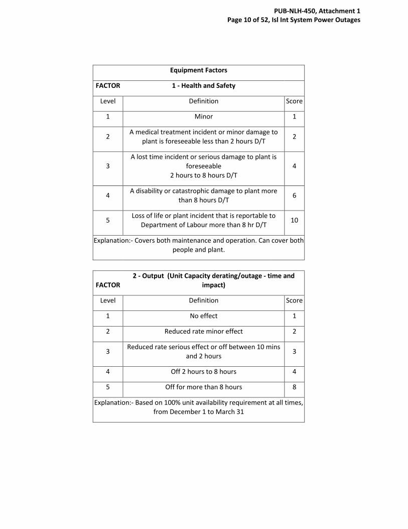
Equipment Factors
FACTOR 1 - Health and Safety
Level Definition Score
1 Minor 1
2 A medical treatment incident or minor damage to plant is foreseeable less than 2 hours D/T 2
3 A lost time incident or serious damage to plant is
foreseeable 2 hours to 8 hours D/T
4
4 A disability or catastrophic damage to plant more than 8 hours D/T 6
5 Loss of life or plant incident that is reportable to Department of Labour more than 8 hr D/T 10
Explanation:- Covers both maintenance and operation. Can cover both people and plant.
FACTOR
2 - Output (Unit Capacity derating/outage - time and impact)
Level Definition Score
1 No effect 1
2 Reduced rate minor effect 2
3 Reduced rate serious effect or off between 10 mins and 2 hours 3
4 Off 2 hours to 8 hours 4
5 Off for more than 8 hours 8
Explanation:- Based on 100% unit availability requirement at all times, from December 1 to March 31
PUB-NLH-450, Attachment 1 Page 10 of 52, Isl Int System Power Outages
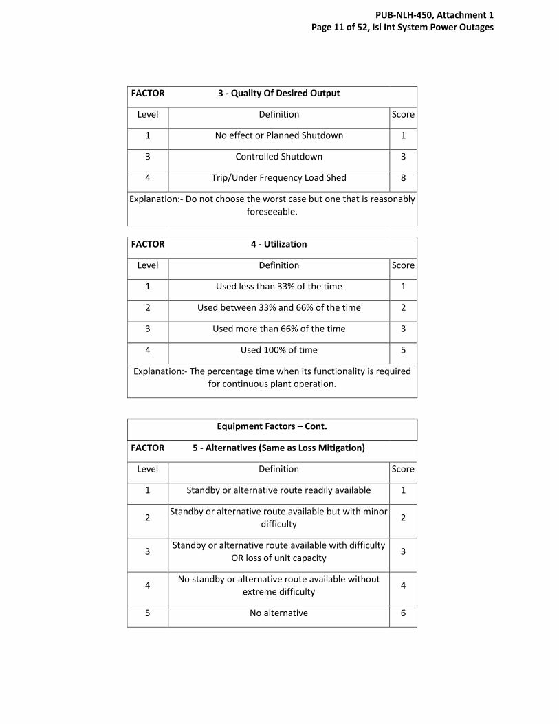
FACTOR 3 - Quality Of Desired Output
Level Definition Score
1 No effect or Planned Shutdown 1
3 Controlled Shutdown 3
4 Trip/Under Frequency Load Shed 8
Explanation:- Do not choose the worst case but one that is reasonably foreseeable.
FACTOR 4 - Utilization
Level Definition Score
1 Used less than 33% of the time 1
2 Used between 33% and 66% of the time 2
3 Used more than 66% of the time 3
4 Used 100% of time 5
Explanation:- The percentage time when its functionality is required for continuous plant operation.
Equipment Factors – Cont.
FACTOR 5 - Alternatives (Same as Loss Mitigation)
Level Definition Score
1 Standby or alternative route readily available 1
2 Standby or alternative route available but with minor difficulty 2
3 Standby or alternative route available with difficulty OR loss of unit capacity
3
4 No standby or alternative route available without extreme difficulty 4
5 No alternative 6
PUB-NLH-450, Attachment 1 Page 11 of 52, Isl Int System Power Outages

FACTOR 6 - Environment
Level Definition
1 No effect
2 Minor local effect - can be contained on site - eg noise/smell
3 More serious local / minor off-plant - liable to result
in discharge to atmosphere or water course eg ammonia/fumes/oil
4 Reportable or exceeds consents - has potential for prosecution
5 More serious off-plant or off-site effect which involves outside services
Explanation:- Use reasonably foreseeable effects rather than worse case. Include dust, noise, gas, liquids etc. Use this factor where the effect on the environment is important. Include any effect caused
while the equipment is breaking down, any knock off effect and any environmental effect due to the maintenance itself.
FACTOR 7 - Time to Effect
Level Definition Score
1 Negligible effect 1
2 More than 24 hours 2
3 Between 2 hours and 24 hours 3
4 Between 30 mins and 2 hours 4
5 Immediate 5
Explanation:- Sometimes the effect of a breakdown is not felt immediately because buffer storage is provided.
PUB-NLH-450, Attachment 1 Page 12 of 52, Isl Int System Power Outages

APPENDIX B
Asset Criticality and Critical Spares Framework
PUB-NLH-450, Attachment 1 Page 13 of 52, Isl Int System Power Outages

Nalcor Energy — Office of Asset Management
Asset Criticality and Critical Spares
Framework
Comments: Total # of
Pages
11
Issued for Use
Name
Date Status/
Revision
Date
Reason for Issue
LTAP Council
Chair Approval
Manager
OAM
Approval
Confidentiality
Note:
This document contains intellectual property of Nalcor Energy and shall not be copied, used
or distributed in whole or in part without the prior written consent from Nalcor Energy.
PUB-NLH-450, Attachment 1 Page 14 of 52, Isl Int System Power Outages

TABLE OF CONTENTS
1. Purpose 1
2. Scope 1
3. Definitions 2
4. Abbreviations and Acronyms 3
5. Responsibilities 3
6. Process Principle 4
6.1 Asset Criticality – Process Critical 4
6.2 Logistics Criteria – Control Critical 5
6.3 Maintenance Types 8
7.0 Process Implementation 8
8. Examples 8
8.1 Spare Part: Fuse 8
8.2 Spare Part: Fyrequel Hydraulic Fluid 9
8.3 Spare Part: HP Heater Drain Pump 10
Appendix
Critical Spares Decision Diagram
PUB-NLH-450, Attachment 1 Page 15 of 52, Isl Int System Power Outages
3
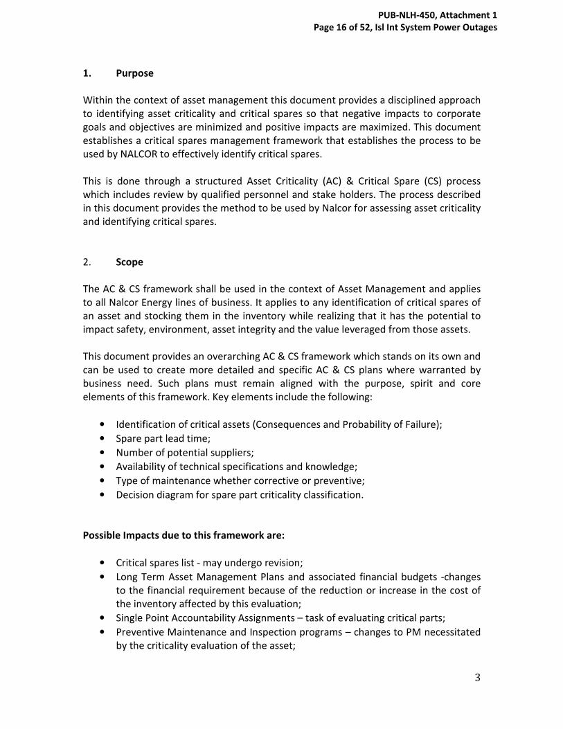
1. Purpose
Within the context of asset management this document provides a disciplined approach
to identifying asset criticality and critical spares so that negative impacts to corporate
goals and objectives are minimized and positive impacts are maximized. This document
establishes a critical spares management framework that establishes the process to be
used by NALCOR to effectively identify critical spares.
This is done through a structured Asset Criticality (AC) & Critical Spare (CS) process
which includes review by qualified personnel and stake holders. The process described
in this document provides the method to be used by Nalcor for assessing asset criticality
and identifying critical spares.
2. Scope
The AC & CS framework shall be used in the context of Asset Management and applies
to all Nalcor Energy lines of business. It applies to any identification of critical spares of
an asset and stocking them in the inventory while realizing that it has the potential to
impact safety, environment, asset integrity and the value leveraged from those assets.
This document provides an overarching AC & CS framework which stands on its own and
can be used to create more detailed and specific AC & CS plans where warranted by
business need. Such plans must remain aligned with the purpose, spirit and core
elements of this framework. Key elements include the following:
• Identification of critical assets (Consequences and Probability of Failure);
• Spare part lead time;
• Number of potential suppliers;
• Availability of technical specifications and knowledge;
• Type of maintenance whether corrective or preventive;
• Decision diagram for spare part criticality classification.
Possible Impacts due to this framework are:
• Critical spares list - may undergo revision;
• Long Term Asset Management Plans and associated financial budgets -changes
to the financial requirement because of the reduction or increase in the cost of
the inventory affected by this evaluation;
• Single Point Accountability Assignments – task of evaluating critical parts;
• Preventive Maintenance and Inspection programs – changes to PM necessitated
by the criticality evaluation of the asset;
PUB-NLH-450, Attachment 1 Page 16 of 52, Isl Int System Power Outages
4
• Assigned Roles and Responsibilities for Asset Management Functions- criticality
evaluation is a responsibility for asset management personnel;
• Operating budgets – changes to budget due to possible new requirement caused
by asset criticality evaluation.
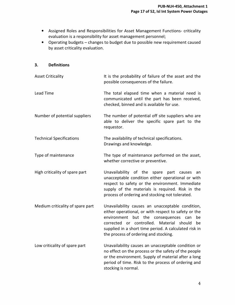
3. Definitions
Asset Criticality It is the probability of failure of the asset and the
possible consequences of the failure.
Lead Time The total elapsed time when a material need is
communicated until the part has been received,
checked, binned and is available for use.
Number of potential suppliers The number of potential off site suppliers who are
able to deliver the specific spare part to the
requestor.
Technical Specifications The availability of technical specifications.
Drawings and knowledge.
Type of maintenance The type of maintenance performed on the asset,
whether corrective or preventive.
High criticality of spare part Unavailability of the spare part causes an
unacceptable condition either operational or with
respect to safety or the environment. Immediate
supply of the materials is required. Risk in the
process of ordering and stocking not tolerated.
Medium criticality of spare part Unavailability causes an unacceptable condition,
either operational, or with respect to safety or the
environment but the consequences can be
corrected or controlled. Material should be
supplied in a short time period. A calculated risk in
the process of ordering and stocking.
Low criticality of spare part Unavailability causes an unacceptable condition or
no effect on the process or the safety of the people
or the environment. Supply of material after a long
period of time. Risk to the process of ordering and
stocking is normal.
PUB-NLH-450, Attachment 1 Page 17 of 52, Isl Int System Power Outages

5
4. Abbreviations and Acronyms
AC Asset Criticality
CS Critical Spares
PM Preventive Maintenance
CM Corrective Maintenance
SPA Single Point Accountable
5. Responsibilities
Single Point Accountable The SPA will identify asset criticality ratings and
critical spares for all assets under his/her
accountability. They may consult the Asset
Specialist, Planners Front Line Supervisors, Stores
Supervisor and Shift Supervisors for their input.
They will submit the critical parts list to the
Manager of Long Term Asset Planning for approval
and procurement.
Manager -
Long Term Asset Planning The Manager/Long Term Asset Planning has the
authority to either approve or reject the critical
parts evaluation submitted to him/her. He/She will
approve stocking the critical part.
Stores Supervisor The Stores Supervisor will ensure that the critical
parts are ordered, stocked correctly and made
available when needed.
Office of Asset Management The Office of Asset Management coordinates
consistency and best practices for critical spares
across all lines of business.
6. Process Principle
Spare part criticality is approached from two perspectives: process criticality and control
criticality. A spare part is considered process critical if its failure or malfunction can
result in negative consequences for normal operations, ie. safety, environmental,
PUB-NLH-450, Attachment 1 Page 18 of 52, Isl Int System Power Outages

6
reliability /production loss. Control criticality refers to the logistic characteristics
namely, lead time, availability of technical specifications and number of potential
suppliers. In terms of control criticality a spare part is considered critical if the possibility
to assure immediate availability of the part is difficult to control.
The number of factors affecting criticality has been limited to the most significant to
keep the multi criteria evaluation manageable, flexible and generalizable. A total of five
attributes are analyzed in a two stage approach using an Asset Criticality Risk Matrix and
a Critical Spare Decision Diagram. The basic idea is to guide the analyst towards the best
criticality class of the spare part. The five attributes are listed in table 6.1 with asset
criticality recognized as being the most important factor to be considered when
evaluating critical spares for the asset.
PUB-NLH-450, Attachment 1 Page 19 of 52, Isl Int System Power Outages
7
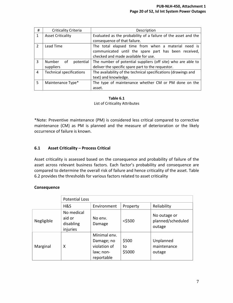
# Criticality Criteria Description
1 Asset Criticality Evaluated as the probability of a failure of the asset and the
consequence of that failure.
2 Lead Time The total elapsed time from when a material need is
communicated until the spare part has been received,
checked and made available for use.
3 Number of potential
suppliers
The number of potential suppliers (off site) who are able to
deliver the specific spare part to the requestor.
4 Technical specifications The availability of the technical specifications (drawings and
text) and knowledge.
5 Maintenance Type* The type of maintenance whether CM or PM done on the
asset.
Table 6.1
List of Criticality Attributes
*Note: Preventive maintenance (PM) is considered less critical compared to corrective
maintenance (CM) as PM is planned and the measure of deterioration or the likely
occurrence of failure is known.
6.1 Asset Criticality – Process Critical
Asset criticality is assessed based on the consequence and probability of failure of the
asset across relevant business factors. Each factor’s probability and consequence are
compared to determine the overall risk of failure and hence criticality of the asset. Table
6.2 provides the thresholds for various factors related to asset criticality
Consequence
Potential Loss
H&S Environment Property Reliability
Negligible
No medical
aid or
disabling
injuries
No env.
Damage <$500
No outage or
planned/scheduled
outage
Marginal X
Minimal env.
Damage; no
violation of
law; non-
reportable
$500
to
$5000
Unplanned
maintenance
outage
PUB-NLH-450, Attachment 1 Page 20 of 52, Isl Int System Power Outages

8
Moderate X
Mitigatible
env. Damage;
no violation
of law
$5000
to
$50,000
Forced outage –
short interval (<1
week)
Critical
Medical aid
or disabling
injury
Reversible
env. Damage;
no violation
of law
$50,000
to
$500,000
Forced outage –
long interval (>1
week)
Catastrophic
Death or
permanent
disability
Irreversible,
severe env.
Damage;
non-
compliance
>$500,000 Major outage or trip
(>1 month)
Probability
P1 Improbable P < 10-6 per year So unlikely, it can be assumed that occurrence
may not be experienced
P2 Remote 10-6 < P < 10-3 per
year
Unlikely but possible to occur in the life of an
item
P3 Occasional 10-3 < P < 10-2 per
year
Likely to occur sometime in the life of an item
P4 Probable 10-2 < P < 10-1 per
year
Likely to occur several times in the life of an
item
P5 Frequent P > 10-1 per year Likely to occur often in the life of an item
Risk Map
Pro
ba
bili
ty
Frequent MEDIUM
MEDIUM
HIGH
HIGH
HIGH
Probable LOW
MEDIUM
HIGH
HIGH
HIGH
Occasional LOW
MEDIUM
MEDIUM
HIGH
HIGH
Remote LOW
LOW
MEDIUM
MEDIUM
MEDIUM
Improbable LOW
LOW
LOW
LOW
MEDIUM
Negligible Marginal Moderate Critical Catastrophic
Consequence
Table 6.2
Asset Criticality Levels
PUB-NLH-450, Attachment 1 Page 21 of 52, Isl Int System Power Outages

9
6.2 Logistics Criteria – Control Critical
The Control Critical Criteria or “Logistics Criteria” include are Lead Time, Availability of
Technical Specifications and the Number of Potential Suppliers – these have been
defined earlier in this document. To align with the Asset Criticality rankings of High,
Medium and Low the Logistics Criteria also have been given a three level ranking namely
10, 5 and 1 with 10 being the most severe. The three categories are summarized in
Table 6.3. with the criticality weighting in at the top of each criterion.
Weighting 10 5 1
1 Lead Time ˃ 1 Month ˃2Days ≤ 1Month ≤ 2 Days
2 Availability of
Technical
Specifications
Not Available General
Specifications
Available
Detailed
Specifications
Available
3 Number of
Potential
Suppliers
Only One
Supplier
˃1 and ≤3 Suppliers ˃3 Suppliers
Table 6.3
Logistics Criteria
6.3 Maintenance Type
The two types of maintenance, preventive and corrective, must be considered on a case
by case basis. The difference between PM and CM regarding spare part criticality is that
PM provides advance information on the deterioration or the condition of the asset for
ordering spares whereas CM demands spares without notice. Therefore a critical spare
part that is inspected, replaced or repaired during a scheduled PM, is normally kept in
inventory and hence PM has a lower priority and weighting as described in this
procedure.
7.0 Process Implementation
To determine whether or not a spare part is a critical spare the Critical Spares Decision
Diagram shown in appendix 1 is used. The diagram consists of decision nodes and each
node refers to the identified criticality criteria- asset criticality, lead time, technical
specifications, potential suppliers and type of maintenance. The decision path to be
followed is based on the outcome of the alternatives of each decision node. Since asset
criticality is considered as the most important factor, in establishing critical spares, the
PUB-NLH-450, Attachment 1 Page 22 of 52, Isl Int System Power Outages

10
decision diagram starts with this node. The first question of the decision diagram is: to
which asset criticality class does the asset belong to? The answer, whether high,
medium, or low asset criticality will apply a a total scoring of 10, 5, or 1 respectively. The
ranking of asset criticality directs the analyst to the next question: will this spare part be
used as part of a scheduled PM or will it be used in the event of a failure under
corrective maintenance (CM)? As previously stated CM will be weighted more than PM;
a weighting of 10 for CM and 1 for PM – this will be added to the previous number for
asset criticality. The analyst then evaluates the spare part logistics criteria of lead time,
technical specifications and number of potential suppliers and arrives at a scoring for
each of the logistics criteria all to be added together and then added to the running
total already achieved through asset criticality and maintenance type. The total score
obtained at the end of the decision diagram determines whether or not the spare part is
a critical spare.
The maximum score that a spare part can obtain is 50, as described below:
1. Asset Criticality high 10 points
2. Corrective Maintenance 10 points
3. Lead Time more than one month 10 points
4. Technical Specifications not available 10 points
5. Number of potential suppliers one 10 points
Total 50 points
The score for designating a spare as critical is 30 points based on 60% of the maximum
of 50 points. Spare parts scoring 30 or higher through this process are considered as
critical spares.
8. Examples
8.1 Spare Part 600V Fuse (Main Power Feed to MCC ESB34)
Asset MCC ESB34
Some of the critical assets served by MCC ESB34 are:
Turbine turning gear
Jacking oil pump
AC Lube oil flushing oil pump
PUB-NLH-450, Attachment 1 Page 23 of 52, Isl Int System Power Outages
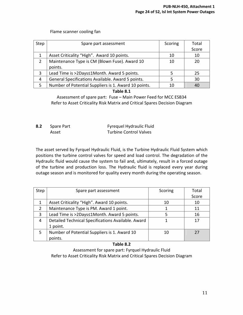
11
Flame scanner cooling fan
Step Spare part assessment Scoring Total
Score
1 Asset Criticality “High”. Award 10 points. 10 10
2 Maintenance Type is CM (Blown Fuse). Award 10
points.
10 20
3 Lead Time is ˃2Days≤1Month. Award 5 points. 5 25
4 General Specifications Available. Award 5 points. 5 30
5 Number of Potential Suppliers is 1. Award 10 points. 10 40
Table 8.1
Assessment of spare part: Fuse – Main Power Feed for MCC ESB34
Refer to Asset Criticality Risk Matrix and Critical Spares Decision Diagram
8.2 Spare Part Fyrequel Hydraulic Fluid
Asset Turbine Control Valves
The asset served by Fyrquel Hydraulic Fluid, is the Turbine Hydraulic Fluid System which
positions the turbine control valves for speed and load control. The degradation of the
Hydraulic fluid would cause the system to fail and, ultimately, result in a forced outage
of the turbine and production loss. The Hydraulic fluid is replaced every year during
outage season and is monitored for quality every month during the operating season.
Step Spare part assessment Scoring Total
Score
1 Asset Criticality “High”. Award 10 points. 10 10
2 Maintenance Type is PM. Award 1 point. 1 11
3 Lead Time is ˃2Days≤1Month. Award 5 points. 5 16
4 Detailed Technical Specifications Available. Award
1 point.
1 17
5 Number of Potential Suppliers is 1. Award 10
points.
10 27
Table 8.2
Assessment for spare part: Fyrquel Hydraulic Fluid
Refer to Asset Criticality Risk Matrix and Critical Spares Decision Diagram
PUB-NLH-450, Attachment 1 Page 24 of 52, Isl Int System Power Outages
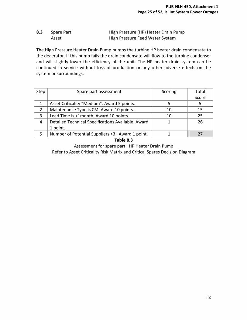
12
8.3 Spare Part High Pressure (HP) Heater Drain Pump
Asset High Pressure Feed Water System
The High Pressure Heater Drain Pump pumps the turbine HP heater drain condensate to
the deaerator. If this pump fails the drain condensate will flow to the turbine condenser
and will slightly lower the efficiency of the unit. The HP heater drain system can be
continued in service without loss of production or any other adverse effects on the
system or surroundings.
Step Spare part assessment Scoring Total
Score
1 Asset Criticality “Medium”. Award 5 points. 5 5
2 Maintenance Type is CM. Award 10 points. 10 15
3 Lead Time is ˃1month. Award 10 points. 10 25
4 Detailed Technical Specifications Available. Award
1 point.
1 26
5 Number of Potential Suppliers ˃3. Award 1 point. 1 27
Table 8.3
Assessment for spare part: HP Heater Drain Pump
Refer to Asset Criticality Risk Matrix and Critical Spares Decision Diagram
PUB-NLH-450, Attachment 1 Page 25 of 52, Isl Int System Power Outages

Critical Spare Decision Diagram
Spare
Part
Asset
Criticality
HIGH
CM
Lead Time
LT > 1 mth
5 2 days > LT < 1 mth
LT < 2 days
Technical
Specifications
Not Available
General Spec. Available
Detail Spec. Available
# of Potential
Suppliers
Only 1 Supplier
>1 but < 3
> 3
PM
Lead Time
LT > 1 mth
5 2 days > LT < 1 mth
LT < 2 days
Technical
Specifications
Not Available
General Spec. Available
Detail Spec. Available
# of Potential
Suppliers
Only 1 Supplier
>1 but < 3
> 3
5 MEDIUM
CM
Lead Time
LT > 1 mth
5 2 days> LT < 1 mth
LT < 2 days
Technical
Specifications
None Available
General Spec. Available
Detail Spec. Available
# of Potential
Suppliers
Only 1 Supplier
> 1 but <3
> 3
PM
Lead Time
LT > 1 mth
5 2 days> LT < 1 mth
LT < 2 days
Technical
Specifications
None Available
General Spec. Available
Detail Spec. Available
# of Potential
Suppliers
Only 1 Supplier
> 1 but <3
> 3
LOW
CM
Lead Time
LT > 1 mth
5 2 days > LT < 1 mth
LT < 2 days
Technical
Specifications
Not Available
General Spec. Available
Detail Spec. Available
# of Potential
Suppliers
Only 1 Supplier
> 1 but < 3
> 3
PM
Lead Time
LT > 1 mth
5 2 days > LT < 1 mth
LT < 2 days
Technical
Specifications
Not Available
General Spec. Available
Detail Spec. Available
# of Potential
Suppliers
Only 1 Supplier
> 1 but < 3
> 3
Appendix
PUB-NLH-450, Attachment 1 Page 26 of 52, Isl Int System Power Outages

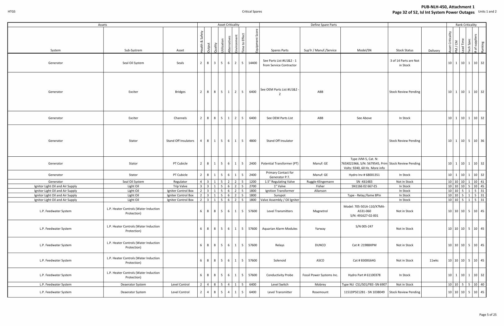
APPENDIX C
Critical Spares Identification Listing
PUB-NLH-450, Attachment 1 Page 27 of 52, Isl Int System Power Outages
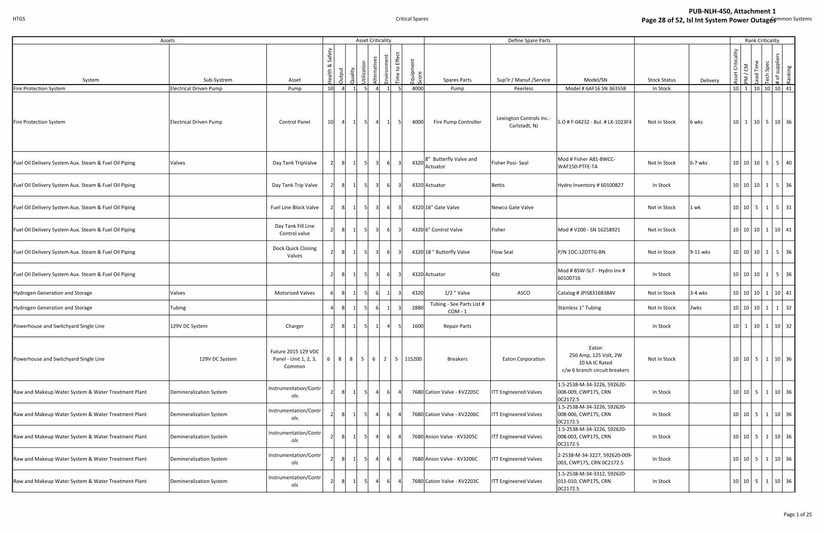
HTGS Critical Spares Common Systems
System Sub-Systrem Asset He
alt
h &
Sa
fety
Ou
tpu
t
Qu
ali
ty
Uti
liza
tio
n
Alt
ern
ati
ve
s
En
vir
on
me
nt
Tim
e t
o E
ffe
ct
Eq
uip
me
nt
Sco
re
Spares Parts Sup'lr / Manuf./Service Model/SN Stock Status Delivery Ass
et
Cri
tica
lity
PM
/ C
M
Lea
d T
ime
Te
ch S
pe
c
# o
f su
pp
lie
rs
Ra
nk
ing
Fire Protection System Electrical Driven Pump Pump 10 4 1 5 4 1 5 4000 Pump Peerless Model # 6AF16 SN 363558 In Stock 10 1 10 10 10 41
Fire Protection System Electrical Driven Pump Control Panel 10 4 1 5 4 1 5 4000 Fire Pump Controller Lexington Controls Inc.-
Carlstadt, NJS.O # F-04232 - Bul. # LX-1023F4 Not in Stock 6 wks 10 1 10 5 10 36
Fuel Oil Delivery System Aux. Steam & Fuel Oil Piping Valves Day Tank TripValve 2 8 1 5 3 6 3 43208" Butterfly Valve and
ActuatorFisher Posi- Seal
Mod # Fisher A81-8WCC-
WAF150-PTFE-TANot In Stock 6-7 wks 10 10 10 5 5 40
Fuel Oil Delivery System Aux. Steam & Fuel Oil Piping Day Tank Trip Valve 2 8 1 5 3 6 3 4320 Actuator Bettis Hydro Inventory # 60100827 In Stock 10 10 10 1 5 36
Fuel Oil Delivery System Aux. Steam & Fuel Oil Piping Fuel Line Block Valve 2 8 1 5 3 6 3 4320 16" Gate Valve Newco Gate Valve Not in Stock 1 wk 10 10 5 1 5 31
Fuel Oil Delivery System Aux. Steam & Fuel Oil PipingDay Tank Fill Line
Control valve2 8 1 5 3 6 3 4320 6" Control Valve Fisher Mod # V200 - SN 16258921 Not in Stock 10 10 10 1 10 41
Fuel Oil Delivery System Aux. Steam & Fuel Oil PipingDock Quick Closing
Valves2 8 1 5 3 6 3 4320 18 " Butterfly Valve Flow Seal P/N 1DC-12DTTG-BN Not in Stock 9-11 wks 10 10 10 1 5 36
Fuel Oil Delivery System Aux. Steam & Fuel Oil Piping 2 8 1 5 3 6 3 4320 Actuator KitzMod # BSW-5LT - Hydro Inv #
60100716In Stock 10 10 10 1 5 36
Hydrogen Generation and Storage Valves Motorized Valves 6 8 1 5 6 1 3 4320 1/2 " Valve ASCO Catalog # JPIS8316B384V Not in Stock 3-4 wks 10 10 10 1 10 41
Hydrogen Generation and Storage Tubing 4 8 1 5 6 1 3 2880Tubing - See Parts List #
COM - 1Stainless 1" Tubing Not in Stock 2wks 10 10 10 1 1 32
Powerhouse and Switchyard Single Line 129V DC System Charger 2 8 1 5 1 4 5 1600 Repair Parts In Stock 10 1 10 1 10 32
Powerhouse and Switchyard Single Line 129V DC System
Future 2015 129 VDC
Panel - Unit 1, 2, 3,
Common
6 8 8 5 6 2 5 115200 Breakers Eaton Corporation
Eaton
250 Amp, 125 Volt, 2W
10 kA IC Rated
c/w 6 branch circuit breakers
Not in Stock 10 10 5 1 10 36
Raw and Makeup Water System & Water Treatment Plant Demineralization SystemInstrumentation/Contr
ols2 8 1 5 4 6 4 7680 Cation Valve - KV2205C ITT Engineered Valves
1.5-2538-M-34-3226, 592620-
008-009, CWP175, CRN
0C2172.5
In Stock 10 10 5 1 10 36
Raw and Makeup Water System & Water Treatment Plant Demineralization SystemInstrumentation/Contr
ols2 8 1 5 4 6 4 7680 Cation Valve - KV2206C ITT Engineered Valves
1.5-2538-M-34-3226, 592620-
008-006, CWP175, CRN
0C2172.5
In Stock 10 10 5 1 10 36
Raw and Makeup Water System & Water Treatment Plant Demineralization SystemInstrumentation/Contr
ols2 8 1 5 4 6 4 7680 Anion Valve - KV3205C ITT Engineered Valves
1.5-2538-M-34-3226, 592620-
008-003, CWP175, CRN
0C2172.5
In Stock 10 10 5 1 10 36
Raw and Makeup Water System & Water Treatment Plant Demineralization SystemInstrumentation/Contr
ols2 8 1 5 4 6 4 7680 Anion Valve - KV3206C ITT Engineered Valves
2-2538-M-34-3227, 592620-009-
003, CWP175, CRN 0C2172.5In Stock 10 10 5 1 10 36
Raw and Makeup Water System & Water Treatment Plant Demineralization SystemInstrumentation/Contr
ols2 8 1 5 4 6 4 7680 Cation Valve - KV2203C ITT Engineered Valves
1.5-2538-M-34-3312, 592620-
011-010, CWP175, CRN
0C2172.5
In Stock 10 10 5 1 10 36
Assets Define Spare Parts Rank Criticality Asset Criticality
Page 1 of 25
PUB-NLH-450, Attachment 1 Page 28 of 52, Isl Int System Power Outages

HTGS Critical Spares Common Systems
System Sub-Systrem Asset He
alt
h &
Sa
fety
Ou
tpu
t
Qu
ali
ty
Uti
liza
tio
n
Alt
ern
ati
ve
s
En
vir
on
me
nt
Tim
e t
o E
ffe
ct
Eq
uip
me
nt
Sco
re
Spares Parts Sup'lr / Manuf./Service Model/SN Stock Status Delivery Ass
et
Cri
tica
lity
PM
/ C
M
Lea
d T
ime
Te
ch S
pe
c
# o
f su
pp
lie
rs
Ra
nk
ing
Assets Define Spare Parts Rank Criticality Asset Criticality
Raw and Makeup Water System & Water Treatment Plant Demineralization SystemInstrumentation/Contr
ols2 8 1 5 4 6 4 7680 Cation Valve - KV2207C ITT Engineered Valves
1.5-2538-M-34-3312, 592620-
011-007, CWP175, CRN
0C2172.5
In Stock 10 10 5 1 10 36
Raw and Makeup Water System & Water Treatment Plant Demineralization SystemInstrumentation/Contr
ols2 8 1 5 4 6 4 7680 Cation Valve - KV2202C ITT Engineered Valves
2-2538-M-34-3325, 592620-014-
003, CWP175, CRN 0C2172.5In Stock 10 10 5 1 10 36
Raw and Makeup Water System & Water Treatment Plant Demineralization SystemInstrumentation/Contr
ols2 8 1 5 4 6 4 7680 Cation Valve - KV2208C ITT Engineered Valves
3-2538-M-34-3350, 592620-015-
003, CWP175, CRN 0C2172.5In Stock 10 10 5 1 10 36
Raw and Makeup Water System & Water Treatment Plant Demineralization SystemInstrumentation/Contr
ols2 8 1 5 4 6 4 7680 Anion Valve - KV3203C ITT Engineered Valves
1.5-2538-M-34-3312, 592620-
011-019, CWP175, CRN
0C2172.5
In Stock 10 10 5 1 10 36
Raw and Makeup Water System & Water Treatment Plant Demineralization SystemInstrumentation/Contr
ols2 8 1 5 4 6 4 7680 Anion Valve - KV3207C ITT Engineered Valves
1.5-2538-M-34-3312, 592620-
011-016, CWP175, CRN
0C2172.5
In Stock 10 10 5 1 10 36
Raw and Makeup Water System & Water Treatment Plant Demineralization SystemInstrumentation/Contr
ols2 8 1 5 4 6 4 7680 Anion Valve - KV3202C ITT Engineered Valves
1.5-2538-M-34-3312, 592620-
011-013, CWP175, CRN
0C2172.5
In Stock 10 10 5 1 10 36
Raw and Makeup Water System & Water Treatment Plant Demineralization SystemInstrumentation/Contr
ols2 8 1 5 4 6 4 7680 Anion Valve - KV3208C ITT Engineered Valves
3-2538-M-34-3350, 592620-015-
004, CWP175, CRN 0C2172.5In Stock 10 10 5 1 10 36
Raw and Makeup Water System & Water Treatment Plant Demineralization SystemInstrumentation/Contr
ols2 8 1 5 4 6 4 7680 Mixed Bed Valve - KV4003B ITT Engineered Valves
1.5-2538-M-34-3312, 592620-
011-023, CWP175, CRN
0C2172.5
In Stock 10 10 5 1 10 36
Raw and Makeup Water System & Water Treatment Plant Demineralization SystemInstrumentation/Contr
ols2 8 1 5 4 6 4 7680 Mixed Bed Valve - KV4004A ITT Engineered Valves
1.5-2538-M-34-3226, 592620-
007-001, CWP175, CRN
0C2172.5
In Stock 10 10 5 1 10 36
Raw and Makeup Water System & Water Treatment Plant Demineralization SystemInstrumentation/Contr
ols2 8 1 5 4 6 4 7680 Mixed Bed Valve - KV4005B ITT Engineered Valves
1.5-2538-M-34-3226, 592620-
007-003, CWP175, CRN
0C2172.5
In Stock 10 10 5 1 10 36
Raw and Makeup Water System & Water Treatment Plant Demineralization SystemInstrumentation/Contr
ols2 8 1 5 4 6 4 7680 Mixed Bed Valve - KV4006B ITT Engineered Valves
1.5-2538-M-34-3312, 592620-
011-021, CWP175, CRN
0C2172.5
In Stock 10 10 5 1 10 36
Raw and Makeup Water System & Water Treatment Plant Demineralization SystemInstrumentation/Contr
ols2 8 1 5 4 6 4 7680 Mixed Bed Valve - KV4007B ITT Engineered Valves
2-2538-M-34-3325, 592620-014-
005, CWP175, CRN 0C2172.5In Stock 10 10 5 1 10 36
Raw and Makeup Water System & Water Treatment Plant Demineralization SystemInstrumentation/Contr
ols2 8 1 5 4 6 4 7680 Mixed Bed Valve - KV4008B ITT Engineered Valves
1.5-2538-M-34-3312, 592620-
010-002, CWP175, CRN
0C2172.5
In Stock 10 10 5 1 10 36
Raw and Makeup Water System & Water Treatment Plant Demineralization SystemInstrumentation/Contr
ols2 8 1 5 4 6 4 7680 Mixed Bed Valve - KV4009B ITT Engineered Valves
2-2538-M-34-3325, 592620-012-
002, CWP175, CRN 0C2172.5In Stock 10 10 5 1 10 36
Raw and Makeup Water System & Water Treatment Plant Demineralization SystemInstrumentation/Contr
ols2 8 1 5 4 6 4 7680 Mixed Bed Valve - KV4010A ITT Engineered Valves
2-2538-M-34-3325, 592620-014-
006, CWP175, CRN 0C2172.5In Stock 10 10 5 1 10 36
Raw and Makeup Water System & Water Treatment Plant Demineralization SystemInstrumentation/Contr
ols2 8 1 5 4 6 4 7680 Mixed Bed Valve - KV4011A ITT Engineered Valves
3-2538-M-34-3350, 592620-015-
007, CWP150In Stock 10 10 5 1 10 36
Raw and Makeup Water System & Water Treatment Plant Demineralization SystemInstrumentation/Contr
ols2 8 1 5 4 6 4 7680 Mixed Bed Valve - PCV4071 Fisher
Type 95 H-123, S/N: 1-97, PSIG,
Max Outlet & Inlet: 300 @ 180
deg.F, Spring Range: 5-80, Trim
Material BUNAN
Not in Stock 6-8 Wks 10 10 10 1 10 41
Raw and Makeup Water System & Water Treatment Plant Demineralization SystemInstrumentation/Contr
ols2 8 1 5 4 6 4 7680 Silica Analyzer HACH Series 5000, S/N: 090200309657 Not in Stock 10 1 10 1 10 32
Page 2 of 25
PUB-NLH-450, Attachment 1 Page 29 of 52, Isl Int System Power Outages

HTGS Critical Spares Common Systems
System Sub-Systrem Asset He
alt
h &
Sa
fety
Ou
tpu
t
Qu
ali
ty
Uti
liza
tio
n
Alt
ern
ati
ve
s
En
vir
on
me
nt
Tim
e t
o E
ffe
ct
Eq
uip
me
nt
Sco
re
Spares Parts Sup'lr / Manuf./Service Model/SN Stock Status Delivery Ass
et
Cri
tica
lity
PM
/ C
M
Lea
d T
ime
Te
ch S
pe
c
# o
f su
pp
lie
rs
Ra
nk
ing
Assets Define Spare Parts Rank Criticality Asset Criticality
Raw and Makeup Water System & Water Treatment Plant Demineralization SystemInstrumentation/Contr
ols2 8 1 5 4 6 4 7680 Sample Heater HACH
Model 48500, P/N: 48500-60,
S/N: 950200000202Not in Stock 10 1 10 1 10 32
Raw and Makeup Water System & Water Treatment Plant Demineralization SystemInstrumentation/Contr
ols2 8 1 5 4 6 4 7680 Sodium Monitor Orion Research Inc.
1800 Series, Model 1811EL, P/N:
214580-001, Amplifier: ORION
2A01, Signal Output: ORION
2B01
In Stock 10 1 10 1 10 32
Raw and Makeup Water System & Water Treatment Plant Clarifier Agitator 4 8 1 5 2 2 3 1920 Frequency Drive Sterling Power Systems Model M1530C Not in Stock 1-10 days 10 10 10 1 10 41
Raw and Makeup Water System & Water Treatment Plant Clarifier Agitator 4 8 1 5 2 2 3 1920
Recirculator - Double
Induction Speed Reducer -
In Stock
Sterling Power Systems Hydro Inventory # 42000070 In Stock 10 1 10 1 10 32
Page 3 of 25
PUB-NLH-450, Attachment 1 Page 30 of 52, Isl Int System Power Outages

HTGS Critical Spares Units 1 and 2
System Sub-Systrem Asset He
alt
h &
Sa
fety
Ou
tpu
t
Qu
ali
ty
Uti
liza
tio
n
Alt
ern
ati
ve
s
En
vir
on
me
nt
Tim
e t
o E
ffe
ct
Eq
uip
me
nt
Sco
re
Spares Parts Sup'lr / Manuf./Service Model/SN Stock Status Delivery Ass
et
Cri
tica
lity
PM
/ C
M
Lea
d T
ime
Te
ch S
pe
c
# o
f su
pp
lie
rs
Ra
nk
ing
Circulating Water and Screen Wash System CW Discharge Valves Butterfly Valve 4 3 8 5 2 1 5 4800 36" Butterfly Valve
Manuf Keystone -
Distibutor Supplier
Westlund
Not in Stock 3-4wks 10 1 10 1 10 32
Circulating Water and Screen Wash System CW Discharge Valves Butterfly Valve 4 3 8 5 2 1 5 4800 Actuator Limitorgue Type SMB Size / SN 109107 In Stock 10 1 10 1 10 32
Combustion Air & Gas Instruments Burner Management Burner Automation 6 8 8 5 6 6 5 345600 Network Interface Modules Manuf: Alstom IM-100 Not in Stock 10 10 10 1 10 41
Combustion Air & Gas Instruments Burner Management Burner Automation 6 8 8 5 6 6 5 345600 Master Fuel Trip Relays Manuf: Allen-Bradley Type P Not in Stock 3-4 W 10 10 10 5 10 45
Combustion Air & Gas Instruments Burner Management Burner Automation 6 8 8 5 6 6 5 345600 DCS Control Processor Manuf: Foxboro FCP-270 Not in Stock 4-5 wks 10 10 10 5 10 45
Combustion Air & Gas Instruments Burner ManagementElevation Oil Flow
Transmitter1 8 8 5 6 4 5 38400 Meter & Sensor Manuf: Micro Motion
Model: DS300S156SC
S/N: 128353Not in Stock 10 10 5 5 5 35
Combustion Air & Gas Instruments Burner ManagementElevation Oil Flow
Transmitter1 8 8 5 6 4 5 38400 Transmitter Elite
Model: RFT 9739E1SUJ - SN
103550Not in Stock 10 10 5 5 5 35
Combustion Air & Gas Instruments Burner Management Flame Scanners 4 8 8 5 1 4 5 25600 24Vdc Scanner Power Manuf: Weidmuller Not in Stock 10 10 5 5 10 40
Combustion Air & Gas Instruments Burner Management Positioner 2 3 3 5 2 4 5 3600
2.5" x 5 "Pneumatic
PowerPositioner
In Stock
Manuf. Hegan Model # 301 - In Stock >3wks 10 1 10 5 10 36
Combustion Air & Gas Instruments Burner Management Air Flow Transmitters 1 3 3 5 3 4 5 2700 Transmitter ABB 2600 T Series - SN 6804000064 In Stock 10 10 10 5 10 45
Combustion Air & Gas Instruments Burner ManagementOil Flow Transmiitter
1 3 3 5 3 4 5 2700 Transmitter - Unit 1 Manuf: Micro MotionModel: RFT9739E4SCA
S/N: 2053736Not in Stock 10 10 5 5 10 40
Combustion Air & Gas Instruments Burner ManagementOil Flow Transmiitter
1 3 3 5 3 4 5 2700 Sensor - Unit 2 Manuf: Micro MotionModel: DS300S156SC
S/N: 103550Not in Stock 10 10 5 5 10 40
Combustion Air & Gas Instruments Burner ManagementOil Flow Transmiitter
1 3 3 5 3 4 5 2700 Transmitter - Unit 2 Manuf: Micro MotionModel: RFT9739E1SUJ
S/N: 1530909Not in Stock 10 10 5 5 10 40
Condenser Air Extraction System Vacuum Breakers 2 8 8 5 3 1 5 9600 6' Flanged Hydro Part # 54900047 In Stock 10 1 10 5 5 31
Condenser Air Extraction System Mechanical Vacuum Pumps Motor 2 8 3 5 1 1 5 1200 Motor GE Mod# 125247 / 1005501 Not in Stock 20 - 22 wks 10 1 10 5 5 31
Generator Rotor Rotor 4 8 8 5 6 2 5 76800 Rotor Canadian General Electric
Unit 1: Generator No.: 980485
Unit 2: Generator No.: 980486
See addition Info Tab
Stock Review Pending 10 1 10 5 10 36
Generator Rotor Rotor Poles 4 8 8 5 6 2 5 76800 Rotor Poles Canadian General Electric Not in Stock 10 1 10 5 10 36
Generator Stator 4 8 8 5 6 2 5 76800Stator and Brush Rigging
AssemblyCanadian General Electric
Unit 1: Generator No.: 980485
Unit 2: Generator No.: 980486
See addition Info Tab
Not in Stock 10 1 10 5 10 36
Generator Stator Stator Poles 4 8 8 5 6 2 5 76800 Stator Poles Not in Stock 10 1 10 5 10 36
Rank Criticality Assets Asset Criticality Define Spare Parts
Page 4 of 25
PUB-NLH-450, Attachment 1 Page 31 of 52, Isl Int System Power Outages
HTGS Critical Spares Units 1 and 2
System Sub-Systrem Asset He
alt
h &
Sa
fety
Ou
tpu
t
Qu
ali
ty
Uti
liza
tio
n
Alt
ern
ati
ve
s
En
vir
on
me
nt
Tim
e t
o E
ffe
ct
Eq
uip
me
nt
Sco
re
Spares Parts Sup'lr / Manuf./Service Model/SN Stock Status Delivery Ass
et
Cri
tica
lity
PM
/ C
M
Lea
d T
ime
Te
ch S
pe
c
# o
f su
pp
lie
rs
Ra
nk
ing
Rank Criticality Assets Asset Criticality Define Spare Parts
Generator Seal Oil System Seals 2 8 3 5 6 2 5 14400See Parts List #U1&2 - 1
from Service Contractor
3 of 14 Parts are Not
in Stock10 1 10 1 10 32
Generator Exciter Bridges 2 8 8 5 1 2 5 6400See OEM Parts List #U1&2 -
2ABB Stock Review Pending 10 1 10 1 10 32
Generator Exciter Channels 2 8 8 5 1 2 5 6400 See OEM Parts List ABB See Above In Stock 10 1 10 1 10 32
Generator Stator Stand Off Insulators 4 8 1 5 6 1 5 4800 Stand Off Insulator Stock Review Pending 10 1 10 5 10 36
Generator Stator PT Cubicle 2 8 1 5 6 1 5 2400 Potential Transformer (PT) Manuf: GE
Type JVM-5, Cat. N:
765X021966, S/N: 5679545, Prim
Volts: 9240, 60 Hz. More info
Stock Review Pending 10 1 10 1 10 32
Generator Stator PT Cubicle 2 8 1 5 6 1 5 2400Primary Contact for
Generator P.T.Manuf: GE Hydro Inv # 68001351 In Stock 10 1 10 1 10 32
Generator Seal Oil System Regulator 4 3 1 5 2 2 5 1200 1.5" Regulating Valve Ruggle-Klingemann SN -K61483 Not in Stock 10 10 10 1 10 41
Ignitor Light Oil and Air Supply Light Oil Trip Valve 3 3 1 5 6 2 5 2700 1" Valve Fisher SN1166 02 667-ES In Stock 10 10 10 5 10 45
Ignitor Light Oil and Air Supply Light Oil Igniter Control Box 2 3 1 5 6 2 5 1800 Ignition Transformer Allanson In Stock 10 10 5 1 5 31
Ignitor Light Oil and Air Supply Light Oil Igniter Control Box 2 3 1 5 6 2 5 1800 Sunspot Type - Relay,Flame 8Pin In Stock 10 10 5 1 5 31
Ignitor Light Oil and Air Supply Light Oil Igniter Control Box 2 3 1 5 6 2 5 1800 Valve Assembly / Oil Igniter In Stock 10 10 5 1 5 31
L.P. Feedwater SystemL.P. Heater Controls (Water Induction
Protection)6 8 8 5 6 1 5 57600 Level Transmitters Magnetrol
Model: 705-501A-110/X7MA-
A531-060
S/N: 491627-02-001
Not in Stock 10 10 10 5 10 45
L.P. Feedwater SystemL.P. Heater Controls (Water Induction
Protection)6 8 8 5 6 1 5 57600 Aquarian Alarm Modules Yarway
S/N 005-247Not in Stock 10 10 10 5 10 45
L.P. Feedwater SystemL.P. Heater Controls (Water Induction
Protection)6 8 8 5 6 1 5 57600 Relays DUNCO Cat #: 219BBXPM Not in Stock 10 10 10 5 10 45
L.P. Feedwater SystemL.P. Heater Controls (Water Induction
Protection)6 8 8 5 6 1 5 57600 Solenoid ASCO Cat # 8300G64G Not in Stock 11wks 10 10 10 5 10 45
L.P. Feedwater SystemL.P. Heater Controls (Water Induction
Protection)6 8 8 5 6 1 5 57600 Conductivity Probe Fossil Power Systems Inc. Hydro Part # 61100378 In Stock 10 1 10 1 10 32
L.P. Feedwater System Deaerator System Level Control 2 4 8 5 4 1 5 6400 Level Switch Mobrey Type NU CS1/S01/F83 -SN 6907 Not in Stock 10 10 5 5 10 40
L.P. Feedwater System Deaerator System Level Control 2 4 8 5 4 1 5 6400 Level Transmitter Rosemount 1151DP5E12B1 - SN 1038049 Stock Review Pending 10 10 10 5 10 45
Page 5 of 25
PUB-NLH-450, Attachment 1 Page 32 of 52, Isl Int System Power Outages
HTGS Critical Spares Units 1 and 2
System Sub-Systrem Asset He
alt
h &
Sa
fety
Ou
tpu
t
Qu
ali
ty
Uti
liza
tio
n
Alt
ern
ati
ve
s
En
vir
on
me
nt
Tim
e t
o E
ffe
ct
Eq
uip
me
nt
Sco
re
Spares Parts Sup'lr / Manuf./Service Model/SN Stock Status Delivery Ass
et
Cri
tica
lity
PM
/ C
M
Lea
d T
ime
Te
ch S
pe
c
# o
f su
pp
lie
rs
Ra
nk
ing
Rank Criticality Assets Asset Criticality Define Spare Parts
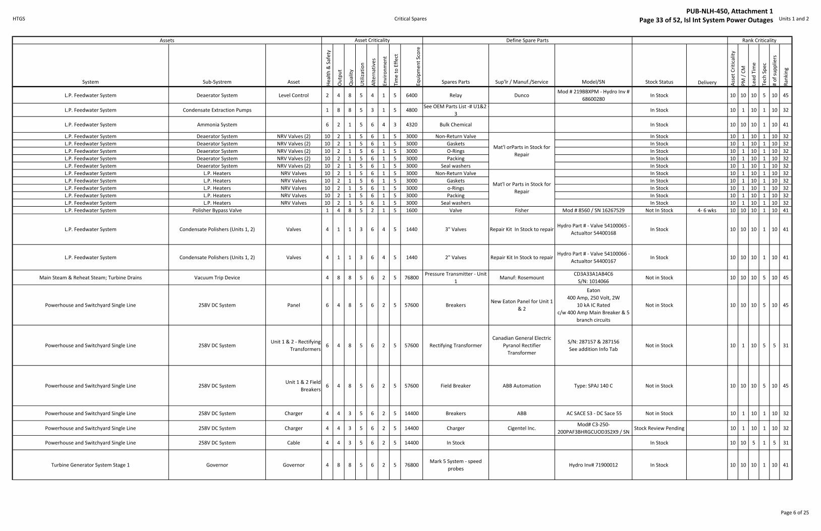
L.P. Feedwater System Deaerator System Level Control 2 4 8 5 4 1 5 6400 Relay DuncoMod # 219BBXPM - Hydro Inv #
68600280In Stock 10 10 10 5 10 45
L.P. Feedwater System Condensate Extraction Pumps 1 8 8 5 3 1 5 4800See OEM Parts List -# U1&2 -
3In Stock 10 1 10 1 10 32
L.P. Feedwater System Ammonia System 6 2 1 5 6 4 3 4320 Bulk Chemical In Stock 10 10 10 1 10 41
L.P. Feedwater System Deaerator System NRV Valves (2) 10 2 1 5 6 1 5 3000 Non-Return Valve In Stock 10 1 10 1 10 32
L.P. Feedwater System Deaerator System NRV Valves (2) 10 2 1 5 6 1 5 3000 Gaskets In Stock 10 1 10 1 10 32
L.P. Feedwater System Deaerator System NRV Valves (2) 10 2 1 5 6 1 5 3000 O-Rings In Stock 10 1 10 1 10 32
L.P. Feedwater System Deaerator System NRV Valves (2) 10 2 1 5 6 1 5 3000 Packing In Stock 10 1 10 1 10 32
L.P. Feedwater System Deaerator System NRV Valves (2) 10 2 1 5 6 1 5 3000 Seal washers In Stock 10 1 10 1 10 32
L.P. Feedwater System L.P. Heaters NRV Valves 10 2 1 5 6 1 5 3000 Non-Return Valve In Stock 10 1 10 1 10 32
L.P. Feedwater System L.P. Heaters NRV Valves 10 2 1 5 6 1 5 3000 Gaskets In Stock 10 1 10 1 10 32
L.P. Feedwater System L.P. Heaters NRV Valves 10 2 1 5 6 1 5 3000 o-Rings In Stock 10 1 10 1 10 32
L.P. Feedwater System L.P. Heaters NRV Valves 10 2 1 5 6 1 5 3000 Packing In Stock 10 1 10 1 10 32
L.P. Feedwater System L.P. Heaters NRV Valves 10 2 1 5 6 1 5 3000 Seal washers In Stock 10 1 10 1 10 32
L.P. Feedwater System Polisher Bypass Valve 1 4 8 5 2 1 5 1600 Valve Fisher Mod # 8560 / SN 16267529 Not In Stock 4- 6 wks 10 10 10 1 10 41
L.P. Feedwater System Condensate Polishers (Units 1, 2) Valves 4 1 1 3 6 4 5 1440 3" Valves Repair Kit In Stock to repairHydro Part # - Valve 54100065 -
Actualtor 54400168 In Stock 10 10 10 1 10 41
L.P. Feedwater System Condensate Polishers (Units 1, 2) Valves 4 1 1 3 6 4 5 1440 2" Valves Repair Kit In Stock to repairHydro Part # - Valve 54100066 -
Actualtor 54400167 In Stock 10 10 10 1 10 41
Main Steam & Reheat Steam; Turbine Drains Vacuum Trip Device 4 8 8 5 6 2 5 76800Pressure Transmitter - Unit
1Manuf: Rosemount
CD3A33A1AB4C6
S/N: 1014066Not in Stock 10 10 10 5 10 45
Powerhouse and Switchyard Single Line 258V DC System Panel 6 4 8 5 6 2 5 57600 BreakersNew Eaton Panel for Unit 1
& 2
Eaton
400 Amp, 250 Volt, 2W
10 kA IC Rated
c/w 400 Amp Main Breaker & 5
branch circuits
Not in Stock 10 10 10 5 10 45
Powerhouse and Switchyard Single Line 258V DC SystemUnit 1 & 2 - Rectifying
Transformers6 4 8 5 6 2 5 57600 Rectifying Transformer
Canadian General Electric
Pyranol Rectifier
Transformer
S/N: 287157 & 287156
See addition Info TabNot in Stock 10 1 10 5 5 31
Powerhouse and Switchyard Single Line 258V DC SystemUnit 1 & 2 Field
Breakers6 4 8 5 6 2 5 57600 Field Breaker ABB Automation Type: SPAJ 140 C Not in Stock 10 10 10 5 10 45
Powerhouse and Switchyard Single Line 258V DC System Charger 4 4 3 5 6 2 5 14400 Breakers ABB AC SACE S3 - DC Sace 55 Not in Stock 10 1 10 1 10 32
Powerhouse and Switchyard Single Line 258V DC System Charger 4 4 3 5 6 2 5 14400 Charger Cigentel Inc.Mod# C3-250-
200PAF3BHRGCUOD3S2X9 / SN Stock Review Pending 10 1 10 1 10 32
Powerhouse and Switchyard Single Line 258V DC System Cable 4 4 3 5 6 2 5 14400 In Stock In Stock 10 10 5 1 5 31
Turbine Generator System Stage 1 Governor Governor 4 8 8 5 6 2 5 76800Mark 5 System - speed
probesHydro Inv# 71900012 In Stock 10 10 10 1 10 41
Mat'l orParts in Stock for
Repair
Mat'l or Parts in Stock for
Repair
Page 6 of 25
PUB-NLH-450, Attachment 1 Page 33 of 52, Isl Int System Power Outages
HTGS Critical Spares Units 1 and 2
System Sub-Systrem Asset He
alt
h &
Sa
fety
Ou
tpu
t
Qu
ali
ty
Uti
liza
tio
n
Alt
ern
ati
ve
s
En
vir
on
me
nt
Tim
e t
o E
ffe
ct
Eq
uip
me
nt
Sco
re
Spares Parts Sup'lr / Manuf./Service Model/SN Stock Status Delivery Ass
et
Cri
tica
lity
PM
/ C
M
Lea
d T
ime
Te
ch S
pe
c
# o
f su
pp
lie
rs
Ra
nk
ing
Rank Criticality Assets Asset Criticality Define Spare Parts
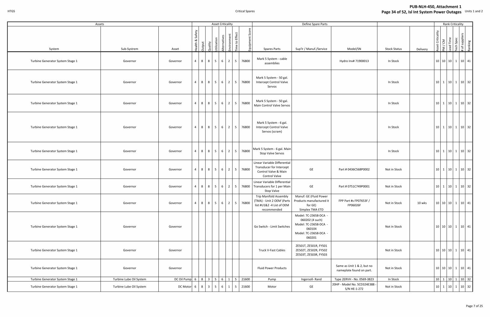
Turbine Generator System Stage 1 Governor Governor 4 8 8 5 6 2 5 76800Mark 5 System - cable
assembliesHydro Inv# 71900013 In Stock 10 10 10 1 10 41
Turbine Generator System Stage 1 Governor Governor 4 8 8 5 6 2 5 76800
Mark 5 System - 50 gal.
Intercept Control Valve
Servos
In Stock 10 1 10 1 10 32
Turbine Generator System Stage 1 Governor Governor 4 8 8 5 6 2 5 76800Mark 5 System - 50 gal.
Main Control Valve ServosIn Stock 10 1 10 1 10 32
Turbine Generator System Stage 1 Governor Governor 4 8 8 5 6 2 5 76800
Mark 5 System - 6 gal.
Intercept Control Valve
Servos (scram)
In Stock 10 1 10 1 10 32
Turbine Generator System Stage 1 Governor Governor 4 8 8 5 6 2 5 76800Mark 5 System - 6 gal. Main
Stop Valve ServosIn Stock 10 1 10 1 10 32
Turbine Generator System Stage 1 Governor Governor 4 8 8 5 6 2 5 76800
Linear Variable Differential
Transducer for Intercept
Control Valve & Main
Control Valve
GE Part # 0436C568P0002 Not in Stock 10 1 10 1 10 32
Turbine Generator System Stage 1 Governor Governor 4 8 8 5 6 2 5 76800
Linear Variable Differential
Transducers for 1 per Main
Stop Valve
GE Part # 0751C749P0001 Not in Stock 10 1 10 1 10 32
Turbine Generator System Stage 1 Governor Governor 4 8 8 5 6 2 5 76800
Trip Manifold Assembly
(TMA) - Unit 2 OEM \Parts
list #U1&2 -4 List of OEM
recommended
Manuf: GE (Fluid Power
Products manufactured it
for GE)
Simplex TMA ETD
FPP Part #s FP07653F /
FP06026FNot in Stock 10 wks 10 10 10 1 10 41
Turbine Generator System Stage 1 Governor Governor Go Switch - Limit Switches
Model: 7C-23658-DCA -
060202 (4 such)
Model: 7C-23658-DCA -
060104
Model: 7C-23658-DCA -
060201
Not in Stock 10 10 10 1 10 41
Turbine Generator System Stage 1 Governor Governor Truck V-Fast Cables
ZE501T, ZE501R, FY501
ZE502T, ZE502R, FY502
ZE503T, ZE503R, FY503
Not in Stock 10 10 10 1 10 41
Turbine Generator System Stage 1 Governor Governor Fluid Power ProductsSame as Unit 1 & 2, but no
nameplate found on part.Not in Stock 10 10 10 1 10 41
Turbine Generator System Stage 1 Turbine Lube Oil System DC Oil Pump 6 8 3 5 6 1 5 21600 Pump Ingersoll- Rand Type 2ERVH - No. 0569-3823 In Stock 10 1 10 1 10 32
Turbine Generator System Stage 1 Turbine Lube Oil System DC Motor 6 8 3 5 6 1 5 21600 Motor GE20HP - Model No. 5CD324E388 -
S/N HE-1-272Not in Stock 10 1 10 1 10 32
Page 7 of 25
PUB-NLH-450, Attachment 1 Page 34 of 52, Isl Int System Power Outages

HTGS Critical Spares Units 1 and 2
System Sub-Systrem Asset He
alt
h &
Sa
fety
Ou
tpu
t
Qu
ali
ty
Uti
liza
tio
n
Alt
ern
ati
ve
s
En
vir
on
me
nt
Tim
e t
o E
ffe
ct
Eq
uip
me
nt
Sco
re
Spares Parts Sup'lr / Manuf./Service Model/SN Stock Status Delivery Ass
et
Cri
tica
lity
PM
/ C
M
Lea
d T
ime
Te
ch S
pe
c
# o
f su
pp
lie
rs
Ra
nk
ing
Rank Criticality Assets Asset Criticality Define Spare Parts
Turbine Generator System Stage 1 Turbine Lube Oil System Pressure Switches 6 8 3 5 6 1 5 21600 Switch Square D Type ACW5S34 In Stock 10 1 10 1 10 32
Turbine Generator System Stage 1 Hydraulic Fluid System Fluid Pumps 4 8 8 5 1 2 5 12800 Pump HartmanCat # PV320R-BV1-B4 - P/N #
32002-23 - S/N HVJ17000In Stock 10 10 10 5 10 45
Turbine Generator System Stage 1 Turbine Lube Oil System AC Oil Pumps 2 8 8 5 1 2 5 6400 Pump Ingersoll- Rand DC same as AC In Stock 10 1 10 5 10 36
Turbine Generator System Stage 1 Turbine Lube Oil System AC Motor 2 8 8 5 1 2 5 6400 Motor GEMod#
5KS254DAE125/SNFHFT154S047In Stock 10 1 10 1 10 32
Turbine Generator System Stage 1 Turbine Lube Oil System Pressure Switch 1 2 8 8 5 1 2 5 6400 Switch Barksdale In Stcok Inc # 60100242 In Stock 10 1 10 1 10 32
Turbine Generator System Stage 1 Turbine Lube Oil System Pressure Switch 2 2 8 8 5 1 2 5 6400 Switch Square D Type ACW5S34 In Stock 10 1 10 1 10 32
Turbine Generator System Stage 1 Steam Seal Regulator 2 4 8 5 1 2 5 3200Main Steam Control Valve -
Positioner - Unit 2Fisher, Fieldvue S/N 0020472099,Type: DVC6200 In Stock 10 1 10 1 10 32
Turbine Generator System Stage 1 Steam Seal Regulator 2 4 8 5 1 2 5 3200Main Steam Valve -
Actuator Repair Kit - Unit 1 Fisher
S/N 0020472099, Type 667 Size
46Stock Review Pending 10 1 10 1 10 32
Turbine Generator System Stage 1 Steam Seal Regulator 2 4 8 5 1 2 5 3200Main Steam Control Valve -
Repair Kit - Unit 1 & 2Fisher
S/N 0020472099, Type HPS Size
1Stock Review Pending 10 1 10 1 10 32
Turbine Generator System Stage 1 Steam Seal Regulator 2 4 8 5 1 2 5 3200
Dump Control Valve -
Actuator - Repair Kit - Unit
1 & 2
FisherS/N 0019964151, Type 667 Size
70Stock Review Pending 10 1 10 1 10 32
Turbine Generator System Stage 1 Steam Seal Regulator 2 4 8 5 1 2 5 3200Dump Control Valve - Body -
Repair Kit - Unit 1 & 2Fisher S/N 0019964151, Type ED Size 8 Stock Review Pending 10 1 10 1 10 32
Units 1 & 2 Air & Flue Gas F.D. Fans Unit 1& 2 - Fans 6 8 8 5 4 6 5 230400See Parts List #U1&2 - 5 -
from OEMJames Howdon and Parsons
Contract No. U1 - 0828/2111 U2 -
08228/2112 Not in Stock 4-22wks 10 1 10 10 10 41
Units 1 & 2 Air & Flue Gas Furnace Pressure TX (Trip) 4 4 8 5 6 1 5 19200 Pressure Transmittter ABB 600 T Series - SN 9801R08413 In Stock 10 10 5 1 10 36
Units 1 & 2 Air & Flue Gas Rotary Air HeatersRotating Element &
Bearings4 8 3 5 6 1 5 14400
See OEM Parts List #U1&2-
6 In Stock 10 10 10 1 10 41
Units 1 & 2 Air & Flue Gas Rotary Air Heaters Drive System 2 8 3 5 1 1 5 1200 See OEM Parts List #U1&2- In Stock 10 10 10 1 10 41
Units 1 & 2 Air & Flue Gas Rotary Air Heaters Soot Blowers 4 8 1 5 6 1 2 1920See OEM Parts List #U1&2-
6 Diamond Power Systems
Mod # IKAH / SN 342185-01-G-
0011353In Stock 10 10 10 1 10 41
Units 1 & 2 Fuel Oil System Combustion Control ValveCombustion Control
Valve2 8 8 5 6 2 5 38400 2" Flanged valv Fisher / Atlantic Controls Type 667ED/116616 Not in Stock 10 Weeks 10 10 10 1 10 41
Units 1 & 2 Fuel Oil System Atomizing Steam Valve Atomizing Steam Valve 2 8 8 5 6 2 5 38400 2" Flanged Valve Fisher / Atlantic Controls Type 667ED/CN116610 In Stock 10 Weeks 10 10 5 5 5 35
Units 1 & 2 Fuel Oil System Main Fuel Oil Trip ValveMain Fuel Oil Trip
Valve3 4 8 5 6 2 5 28800 Flanged Valve Fisher / Atlantic Controls Type 667EC/CN116669 Not in Stock 10 Weeks 10 10 10 1 10 41
Units 1 & 2 Fuel Oil System Header Pressure Control ValveHeader Pressure
Control Valve2 8 8 5 4 2 5 25600 Flanged Valve Fisher / Atlantic Controls Type657/CN687321 Not in Stock 10 Weeks 10 10 10 1 10 41
Page 8 of 25
PUB-NLH-450, Attachment 1 Page 35 of 52, Isl Int System Power Outages
HTGS Critical Spares Units 1 and 2
System Sub-Systrem Asset He
alt
h &
Sa
fety
Ou
tpu
t
Qu
ali
ty
Uti
liza
tio
n
Alt
ern
ati
ve
s
En
vir
on
me
nt
Tim
e t
o E
ffe
ct
Eq
uip
me
nt
Sco
re
Spares Parts Sup'lr / Manuf./Service Model/SN Stock Status Delivery Ass
et
Cri
tica
lity
PM
/ C
M
Lea
d T
ime
Te
ch S
pe
c
# o
f su
pp
lie
rs
Ra
nk
ing
Rank Criticality Assets Asset Criticality Define Spare Parts
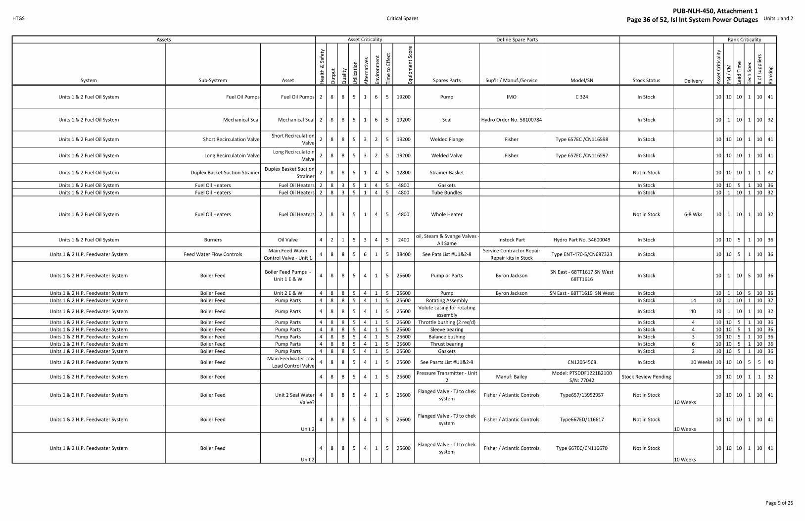
Units 1 & 2 Fuel Oil System Fuel Oil Pumps Fuel Oil Pumps 2 8 8 5 1 6 5 19200 Pump IMO C 324 In Stock 10 10 10 1 10 41
Units 1 & 2 Fuel Oil System Mechanical Seal Mechanical Seal 2 8 8 5 1 6 5 19200 Seal Hydro Order No. 58100784 In Stock 10 1 10 1 10 32
Units 1 & 2 Fuel Oil System Short Recirculation ValveShort Recirculation
Valve2 8 8 5 3 2 5 19200 Welded Flange Fisher Type 657EC /CN116598 In Stock 10 10 10 1 10 41
Units 1 & 2 Fuel Oil System Long Recirculatoin ValveLong Recirculatoin
Valve2 8 8 5 3 2 5 19200 Welded Valve Fisher Type 657EC /CN116597 In Stock 10 10 10 1 10 41
Units 1 & 2 Fuel Oil System Duplex Basket Suction StrainerDuplex Basket Suction
Strainer2 8 8 5 1 4 5 12800 Strainer Basket Not in Stock 10 10 10 1 1 32
Units 1 & 2 Fuel Oil System Fuel Oil Heaters Fuel Oil Heaters 2 8 3 5 1 4 5 4800 Gaskets In Stock 10 10 5 1 10 36
Units 1 & 2 Fuel Oil System Fuel Oil Heaters Fuel Oil Heaters 2 8 3 5 1 4 5 4800 Tube Bundles In Stock 10 1 10 1 10 32
Units 1 & 2 Fuel Oil System Fuel Oil Heaters Fuel Oil Heaters 2 8 3 5 1 4 5 4800 Whole Heater Not in Stock 6-8 Wks 10 1 10 1 10 32
Units 1 & 2 Fuel Oil System Burners Oil Valve 4 2 1 5 3 4 5 2400oil, Steam & Svange Valves -
All SameInstock Part Hydro Part No. 54600049 In Stock 10 10 5 1 10 36
Units 1 & 2 H.P. Feedwater System Feed Water Flow ControlsMain Feed Water
Control Valve - Unit 1 4 8 8 5 6 1 5 38400 See Pats List #U1&2-8
Service Contractor Repair
Repair kits in StockType ENT-470-5/CN687323 In Stock 10 10 5 1 10 36
Units 1 & 2 H.P. Feedwater System Boiler FeedBoiler Feed Pumps -
Unit 1 E & W4 8 8 5 4 1 5 25600 Pump or Parts Byron Jackson
SN East - 68TT1617 SN West
68TT1616In Stock 10 1 10 5 10 36
Units 1 & 2 H.P. Feedwater System Boiler Feed Unit 2 E & W 4 8 8 5 4 1 5 25600 Pump Byron Jackson SN East - 68TT1619 SN West In Stock 10 1 10 5 10 36
Units 1 & 2 H.P. Feedwater System Boiler Feed Pump Parts 4 8 8 5 4 1 5 25600 Rotating Assembly In Stock 14 10 1 10 1 10 32
Units 1 & 2 H.P. Feedwater System Boiler Feed Pump Parts 4 8 8 5 4 1 5 25600Volute casing for rotating
assemblyIn Stock 40 10 1 10 1 10 32
Units 1 & 2 H.P. Feedwater System Boiler Feed Pump Parts 4 8 8 5 4 1 5 25600 Throttle bushing (2 req'd) In Stock 4 10 10 5 1 10 36
Units 1 & 2 H.P. Feedwater System Boiler Feed Pump Parts 4 8 8 5 4 1 5 25600 Sleeve bearing In Stock 4 10 10 5 1 10 36
Units 1 & 2 H.P. Feedwater System Boiler Feed Pump Parts 4 8 8 5 4 1 5 25600 Balance bushing In Stock 3 10 10 5 1 10 36
Units 1 & 2 H.P. Feedwater System Boiler Feed Pump Parts 4 8 8 5 4 1 5 25600 Thrust bearing In Stock 6 10 10 5 1 10 36
Units 1 & 2 H.P. Feedwater System Boiler Feed Pump Parts 4 8 8 5 4 1 5 25600 Gaskets In Stock 2 10 10 5 1 10 36
Units 1 & 2 H.P. Feedwater System Boiler FeedMain Feedwater Low
Load Control Valve4 8 8 5 4 1 5 25600 See Pasrts List #U1&2-9 CN12054568 In Stock 10 Weeks 10 10 10 5 5 40
Units 1 & 2 H.P. Feedwater System Boiler Feed 4 8 8 5 4 1 5 25600Pressure Transmitter - Unit
2Manuf: Bailey
Model: PTSDDF1221B2100
S/N: 77042Stock Review Pending 10 10 10 1 1 32
Units 1 & 2 H.P. Feedwater System Boiler Feed Unit 2 Seal Water
Valve?
4 8 8 5 4 1 5 25600Flanged Valve - TJ to chek
system Fisher / Atlantic Controls Type657/13952957 Not in Stock
10 Weeks
10 10 10 1 10 41
Units 1 & 2 H.P. Feedwater System Boiler Feed
Unit 2
4 8 8 5 4 1 5 25600Flanged Valve - TJ to chek
system Fisher / Atlantic Controls Type667ED/116617 Not in Stock
10 Weeks
10 10 10 1 10 41
Units 1 & 2 H.P. Feedwater System Boiler Feed
Unit 2
4 8 8 5 4 1 5 25600Flanged Valve - TJ to chek
system Fisher / Atlantic Controls Type 667EC/CN116670 Not in Stock
10 Weeks
10 10 10 1 10 41
Page 9 of 25
PUB-NLH-450, Attachment 1 Page 36 of 52, Isl Int System Power Outages

HTGS Critical Spares Units 1 and 2
System Sub-Systrem Asset He
alt
h &
Sa
fety
Ou
tpu
t
Qu
ali
ty
Uti
liza
tio
n
Alt
ern
ati
ve
s
En
vir
on
me
nt
Tim
e t
o E
ffe
ct
Eq
uip
me
nt
Sco
re
Spares Parts Sup'lr / Manuf./Service Model/SN Stock Status Delivery Ass
et
Cri
tica
lity
PM
/ C
M
Lea
d T
ime
Te
ch S
pe
c
# o
f su
pp
lie
rs
Ra
nk
ing
Rank Criticality Assets Asset Criticality Define Spare Parts
Units 1 & 2 H.P. Feedwater System Boiler Feed
Unit 2
4 8 8 5 4 1 5 25600Flanged Valve - TJ to chek
system Fisher / Atlantic Controls Type 667ED/CN116611B Not in Stock
10 Weeks
10 10 10 1 10 41
Units 1 & 2 H.P. Feedwater SystemH.P. Heater Controls (Water Induction
Protection)
Unit #1 - All HP
Heaters6 3 8 5 6 1 5 21600 Level Transmitters Johnson Yokogawa
YA11F-SMS3*B/CSF1/DHC/TP-
W/BR2In Stock 10 10 10 1 1 32
Units 1 & 2 H.P. Feedwater SystemH.P. Heater Controls (Water Induction
Protection)
Unit # 2 - HP Heater # 4
& 6 6 3 8 5 6 1 5 21600 Leve Transmitter Johnson Yokogawa
YA11F-SMS3*B/CSF1/DHC/TP-
W/BR2In Stock 10 10 10 1 1 32
Units 1 & 2 H.P. Feedwater SystemH.P. Heater Controls (Water Induction
Protection)Unit # 2 -HP Heater # 5 6 3 8 5 6 1 5 21600 Level Transmitter Magnetrol
Model No. F24-1B2B-040
(column) & 705-510-11C/7ES-
A448-052 (top of column)
In Stock 10 10 10 1 10 41
Units 1 & 2 H.P. Feedwater SystemH.P. Heater Controls (Water Induction
Protection)Unit 1 - All HP Heaters 6 3 8 5 6 1 5 21600 Aquarian Alarm Modules Yaraway
Aquarian 1000 P /#4 HTR SN 941-
291 Not in Stock 10 10 10 1 10 41
Units 1 & 2 H.P. Feedwater SystemH.P. Heater Controls (Water Induction
Protection)Unit #2 - Heater # 4 & 6 6 3 8 5 6 1 5 21600 Aquarian Alarm Modules Yaraway Aquarian 1000P Not in Stock 10 10 10 1 10 41
Units 1 & 2 H.P. Feedwater SystemH.P. Heater Controls (Water Induction
Protection)Unit # 2 -HP Heater # 5 6 3 8 5 6 1 5 21600 Aquarian Alarm Modules Fossil Power Systems Inc. 1000P / SN 091-066 Not in Stock 10 10 10 1 10 41
Units 1 & 2 H.P. Feedwater SystemH.P. Heater Controls (Water Induction
Protection)
Unit 1 & 2 - All HP
Heaters6 3 8 5 6 1 5 21600 Conductivity Probe Fossil Power Systems Inc. Hydro Part # 61100378 In Stock 10 10 10 1 10 41
Units 1 & 2 H.P. Feedwater SystemH.P. Heater Controls (Water Induction
Protection)
Unit # 1 & 2 - All HP
Heaters 6 3 8 5 6 1 5 21600 Relay Struthers-Dunn
219BBXPLM - Hydro Inv #
6860028In Stock 10 10 5 1 5 31
Units 1 & 2 H.P. Feedwater SystemH.P. Heater Controls (Water Induction
Protection)Unit 1 & 2 6 3 8 5 6 1 5 21600 Solenoid ASCO 8300G64G Not in Stock 10 10 10 1 10 41
Units 1 & 2 H.P. Feedwater System Boiler Feed Suction Valve Limit 4 4 3 5 6 1 5 7200 Oil Tight Limit Switch Allan Bradley Type13 - Cat No. 802T-A - Ser D Not in Stock 10 10 10 1 1 32
Units 1 & 2 H.P. Feedwater System Boiler Feed Suction Valve 4 4 3 5 3 1 5 3600 10" Valve Hopkins In Stock 10 1 10 1 10 32
Units 1 & 2 H.P. Feedwater System H.P. Heaters Motorized Bypass 2 3 8 5 3 1 5 3600 8" Valve Hopkins Manuf # 24930W - In Stock 10 1 10 1 10 32
Units 1 & 2 H.P. Feedwater System H.P. Heaters NRV Valves - Heater # 10 2 1 5 6 1 5 3000 8"- 150# Shutte & Koerting In Stock 10 1 10 1 10 32
Units 1 & 2 H.P. Feedwater System H.P. Heaters NRV Valves - Heater # 10 2 1 5 6 1 5 3000 8"- 300# Shutte & Koerting In Stock 10 1 10 1 10 32
Units 1 & 2 H.P. Feedwater System H.P. Heaters NRV Valves - Heater # 10 2 1 5 6 1 5 3000 8"- 600# Shutte & Koerting In Stock 10 1 10 1 10 32
Units 1 & 2 H.P. Feedwater System Steam DrumLevel Control
Transmitters2 4 8 5 1 1 5 1600 Level Transmitter Rosemount SN 1376331 In Stock 10 10 10 1 1 32
Units 1 & 2 H.P. Feedwater System Boiler Feed Suction Line Safety 4 2 1 5 6 1 5 1200 1/2" x 1" Valve In Stock Hydro Part # 54400134 In Stock 10 10 10 1 1 32
Units 1 & 2 H.P. Feedwater System Boiler Feed
Boiler Feed
Recirculation Valve to
DA
4 3 1 5 4 1 5 1200 4" Valve Butt Weld Hydro Part # 54200036 In Stock 10 10 10 1 10 41
Page 10 of 25
PUB-NLH-450, Attachment 1 Page 37 of 52, Isl Int System Power Outages

HTGS Critical Spares Unit 3
System Sub-Systrem Asset He
alt
h &
Sa
fety
Ou
tpu
t
Qu
ali
ty
Uti
liza
tio
n
Alt
ern
ati
ve
s
En
vir
on
me
nt
Tim
e t
o E
ffe
ct
Eq
uip
me
nt
Sco
re
Spares Parts Sup'lr / Manuf./Service Model/SN Stock Status Delivery Ass
et
Cri
tica
lity
PM
/ C
M
Lea
d T
ime
Te
ch S
pe
c
# o
f su
pp
lie
rs
Ra
nk
ing
Circulating Water and Screen Wash System CW Discharge Valves 4 3 8 5 2 1 5 4800 36 ' Butterfly Valve Keystone Not in Stock 4wks 10 10 10 1 5 36
Circulating Water and Screen Wash System CW Discharge Valves 4 3 8 5 2 1 5 4800CW Butterfly Valve
Actuator Rotork
Type - 16A-FA14A / SN
D12482010101Not in Stock 10 10 10 1 5 36
Combustion Air & Gas Instruments Burner Management Burner Automation 6 8 8 5 6 6 5 345600 Network Interface Modules Alstom IM-100 Not in Stock 10 10 10 1 10 41
Combustion Air & Gas Instruments Burner Management Burner Automation 6 8 8 5 6 6 5 345600 Master Fuel Trip Relays Manuf: Square D Type XUD Not in Stock 3 - 4 wks 10 10 5 1 10 36
Combustion Air & Gas Instruments Burner Management Burner Automation 6 8 8 5 6 6 5 345600 DCS Control Processor Manuf: Foxboro In Stock 10 10 10 1 10 41
Combustion Air & Gas Instruments Burner ManagementElevation Oil Flow
Transmitter1 8 8 5 6 4 5 38400 Meter & Transmitter
Promass -Endress - +
Hauser/Maynard Reese
83/SN7A00121600 read by TJ in
Plant Same SN on meterNot in Stock 2wks 10 10 10 1 1 32
Combustion Air & Gas Instruments Burner Management Elevation Air Dampers 2 3 3 5 2 4 5 3600 Positioner Fisher Type DVC6200 / SN 20646398 In Stock 10 1 10 1 10 32
Condenser Air Extraction System Vacuum Breakers 2 8 8 5 3 1 5 9600 6" Flange Vacuum Breaker Hydro Inv # 54900047 In Stock 10 10 10 1 5 36
Generator Rotor 4 8 8 5 6 2 5 76800 Rotor Hitachi Not in Stock 10 1 10 5 10 36
Generator Rotor Rotor Poles 4 8 8 5 6 2 5 76800 Hitachi Not in Stock 10 1 10 5 10 36
Generator Stator 4 8 8 5 6 2 5 76800Stator and Brush Rigging
AssemblyHitachi Not in Stock 10 1 10 5 10 36
Generator Stator 4 8 8 5 6 2 5 76800Stator and Brush Rigging
AssemblyHitachi Not in Stock 10 1 10 1 10 32
Generator Stator Stator Poles 4 8 8 5 6 2 5 76800 Hitachi Not in Stock 10 1 10 5 10 36
Generator Syncronous Condensor Thrust Bearing 2 8 8 5 6 1 5 19200See Parts List & Estimate by
Supplier - #U3-1Not in Stock 10 1 10 1 10 32
Generator Seal Oil System Seals 2 8 3 5 6 2 5 14400 Seals Stock Review Pending 10 1 10 5 10 36
Generator Exciter Bridges 2 8 8 5 1 2 5 6400 See OEM Parts List -# U3- 2 ABBSee ABB recommended spare
parts list (33 items)In Stock 10 1 10 1 10 32
Generator Exciter Channels 2 8 8 5 1 2 5 6400 See Above ABB See Above In Stock 10 1 10 1 10 32
Asset CriticalityAssets Rank Criticality Define Spare Parts
Page 11 of 25
PUB-NLH-450, Attachment 1 Page 38 of 52, Isl Int System Power Outages

HTGS Critical Spares Unit 3
System Sub-Systrem Asset He
alt
h &
Sa
fety
Ou
tpu
t
Qu
ali
ty
Uti
liza
tio
n
Alt
ern
ati
ve
s
En
vir
on
me
nt
Tim
e t
o E
ffe
ct
Eq
uip
me
nt
Sco
re
Spares Parts Sup'lr / Manuf./Service Model/SN Stock Status Delivery Ass
et
Cri
tica
lity
PM
/ C
M
Lea
d T
ime
Te
ch S
pe
c
# o
f su
pp
lie
rs
Ra
nk
ing
Asset CriticalityAssets Rank Criticality Define Spare Parts
Generator Stator Stand Off Insulators 4 8 1 5 6 1 5 4800 Not in Stock 10 1 10 5 10 36
Generator Stator PT Cubicle 2 8 1 5 6 1 5 2400 Potential Transformer (PT) Manuf: Westinghouse
Style: EES5695, Prim Voltage: 16
kV, S/N: 78123855, 78123856,
78123857, 78123858, 78123859,
78123860
Stock Review Pending 10 1 10 5 10 36
Generator Stator PT Cubicle 2 8 1 5 6 1 5 2400 Fuse Manuf: Westinghouse
Type: CLE PT1 Fuse, Style:
758C433A22, 23000 Volts, 25/60
Hz, Max Cont Curr: 0.5 A, 44kA
RMS Sym, 68kA RMS Asym
In Stock 10 1 10 5 10 36
Ignitor Light Oil and Air Supply Light Oil Trip Valve 3 3 1 5 6 2 5 2700 1" Ball Valve Jamesbury Corp Fig # 33MI- 1052-33Mi Not in Stock 13-14 Wks 10 10 10 1 5 36
Ignitor Light Oil and Air Supply Light Oil Igniter Control Box 2 3 1 5 6 2 5 1800Light Oil / Air Supply
Solenoid ValveASCO Cat# 8342C1 / SN 42605-1 In Stock 10 10 5 1 10 36
Ignitor Light Oil and Air Supply Igniter Control Box 2 3 1 5 6 2 5 1800 Purge Solenoid Valve ASCO Cat # 8262G232 / SN 275125 In Stock 10 10 5 1 10 36
Ignitor Light Oil and Air Supply Igniter Control Box 2 3 1 5 6 2 5 1800 Pneumatic Actuator Quality Controls Mod #QCR16C /SN 8619-1-1 In Stock 10 10 5 1 10 36
Ignitor Light Oil and Air Supply Igniter Control Box 2 3 1 5 6 2 5 1800 Ignition Transformer Allanson In Stock 10 10 5 1 10 36
Ignitor Light Oil and Air Supply Igniter Control Box 2 3 1 5 6 2 5 1800 Relay Phillips Model - RLY 2245 In Stock 10 10 5 1 10 36
Ignitor Light Oil and Air Supply Igniter Control Box 2 3 1 5 6 2 5 1800 Sunspot - Scanner Fossil Power Systems Relay, Flame 8 Pin In Stock 10 10 5 1 10 36
Ignitor Light Oil and Air Supply Igniter Control Box 2 3 1 5 6 2 5 1800 Snap Action Switch Micro Switch Cat# 16CX12,1-24 Not in stock 4 to 6 wks 10 10 10 1 10 41
Ignitor Light Oil and Air Supply Igniter Control Box 2 3 1 5 6 2 5 1800 1/4" Light Oil Air Ball Valves Apollo (#73A-140) 2000#WOG Not in stock 2 wks 10 10 5 1 5 31
L.P. Feedwater SystemL.P. Heater Controls (Water Induction
Protection)6 8 8 5 6 1 5 57600
Level Transmitter LP Heater
#1Manuf: Magnetrol
Model: 705-501A-110/X7MA-
A531-060
S/N: 491627-02-002
In Stock 10 10 10 1 10 41
L.P. Feedwater SystemL.P. Heater Controls (Water Induction
Protection)6 8 8 5 6 1 5 57600 Aquarian Alarm Modules Yarway
S/N 005-243In Stock 10 10 10 1 10 41
L.P. Feedwater SystemL.P. Heater Controls (Water Induction
Protection)6 8 8 5 6 1 5 57600 Solenoid ASCO
Cat No. WPHT 8300B 68 RF - SN
83621Not in Stock 72 days 10 10 10 1 10 41
L.P. Feedwater SystemL.P. Heater Controls (Water Induction
Protection)6 8 8 5 6 1 5 57600 Relay Omron
Type MM4XP DC125 -
Omrom4PDT,7.5A Switching,
Plug-in, Magnetic \blowout
Not in Stock 3-4 wks 10 10 10 1 10 41
L.P. Feedwater SystemL.P. Heater Controls (Water Induction
Protection)6 8 8 5 6 1 5 57600 Conductivity Probe Fossil Power Systems Inc. Hydro Part # 61100378 In Stock 10 10 5 1 10 36
L.P. Feedwater System Deaerator System Deaerator 6 8 3 5 6 1 5 21600 Gauge Glasses In Stock 10 10 10 1 10 41
Page 12 of 25
PUB-NLH-450, Attachment 1 Page 39 of 52, Isl Int System Power Outages
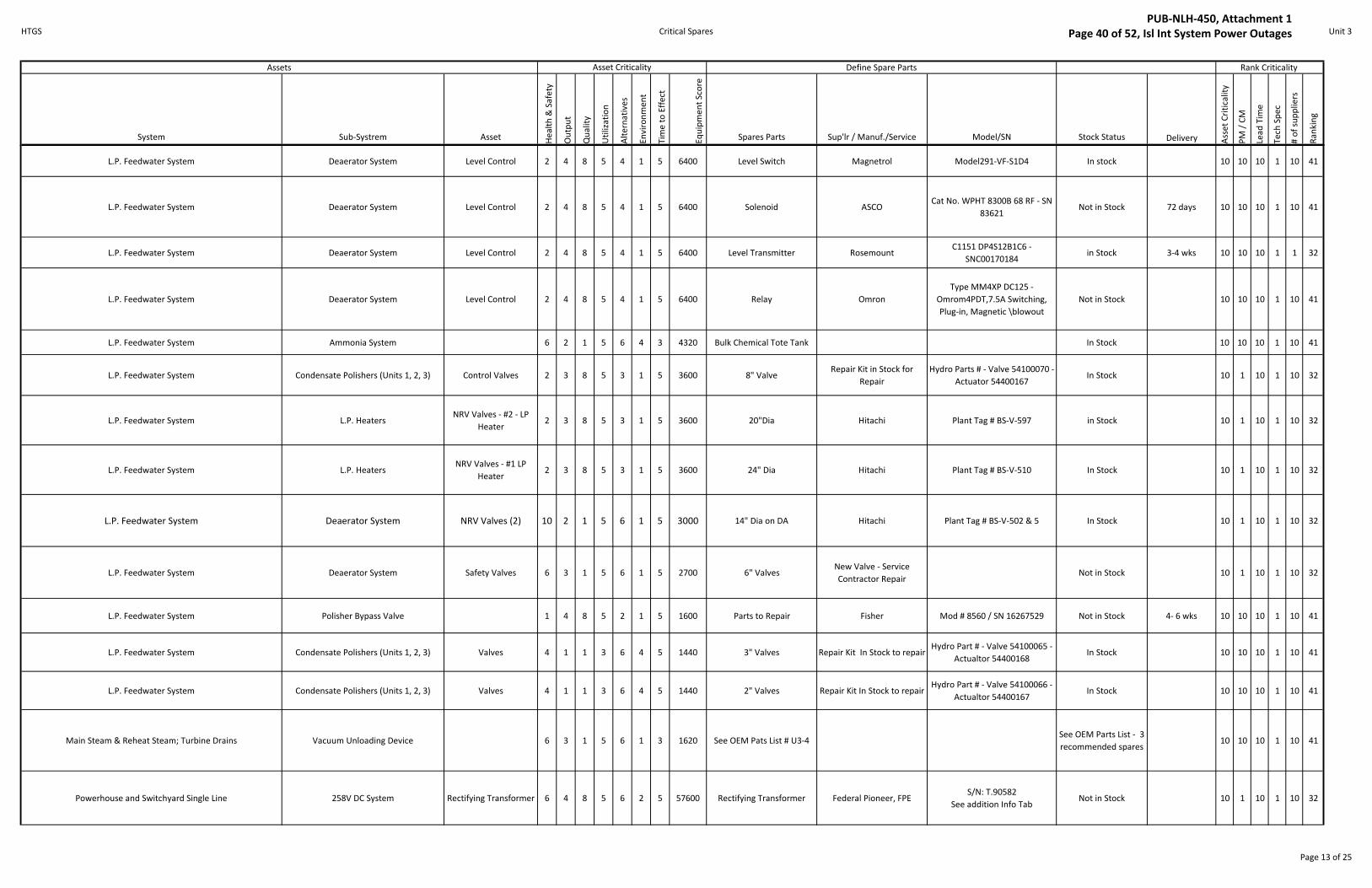
HTGS Critical Spares Unit 3
System Sub-Systrem Asset He
alt
h &
Sa
fety
Ou
tpu
t
Qu
ali
ty
Uti
liza
tio
n
Alt
ern
ati
ve
s
En
vir
on
me
nt
Tim
e t
o E
ffe
ct
Eq
uip
me
nt
Sco
re
Spares Parts Sup'lr / Manuf./Service Model/SN Stock Status Delivery Ass
et
Cri
tica
lity
PM
/ C
M
Lea
d T
ime
Te
ch S
pe
c
# o
f su
pp
lie
rs
Ra
nk
ing
Asset CriticalityAssets Rank Criticality Define Spare Parts
L.P. Feedwater System Deaerator System Level Control 2 4 8 5 4 1 5 6400 Level Switch Magnetrol Model291-VF-S1D4 In stock 10 10 10 1 10 41
L.P. Feedwater System Deaerator System Level Control 2 4 8 5 4 1 5 6400 Solenoid ASCOCat No. WPHT 8300B 68 RF - SN
83621Not in Stock 72 days 10 10 10 1 10 41
L.P. Feedwater System Deaerator System Level Control 2 4 8 5 4 1 5 6400 Level Transmitter RosemountC1151 DP4S12B1C6 -
SNC00170184in Stock 3-4 wks 10 10 10 1 1 32
L.P. Feedwater System Deaerator System Level Control 2 4 8 5 4 1 5 6400 Relay Omron
Type MM4XP DC125 -
Omrom4PDT,7.5A Switching,
Plug-in, Magnetic \blowout
Not in Stock 10 10 10 1 10 41
L.P. Feedwater System Ammonia System 6 2 1 5 6 4 3 4320 Bulk Chemical Tote Tank In Stock 10 10 10 1 10 41
L.P. Feedwater System Condensate Polishers (Units 1, 2, 3) Control Valves 2 3 8 5 3 1 5 3600 8" Valve Repair Kit in Stock for
Repair
Hydro Parts # - Valve 54100070 -
Actuator 54400167In Stock 10 1 10 1 10 32
L.P. Feedwater System L.P. HeatersNRV Valves - #2 - LP
Heater2 3 8 5 3 1 5 3600 20"Dia Hitachi Plant Tag # BS-V-597 in Stock 10 1 10 1 10 32
L.P. Feedwater System L.P. HeatersNRV Valves - #1 LP
Heater2 3 8 5 3 1 5 3600 24" Dia Hitachi Plant Tag # BS-V-510 In Stock 10 1 10 1 10 32
L.P. Feedwater System Deaerator System NRV Valves (2) 10 2 1 5 6 1 5 3000 14" Dia on DA Hitachi Plant Tag # BS-V-502 & 5 In Stock 10 1 10 1 10 32
L.P. Feedwater System Deaerator System Safety Valves 6 3 1 5 6 1 5 2700 6" ValvesNew Valve - Service
Contractor Repair Not in Stock 10 1 10 1 10 32
L.P. Feedwater System Polisher Bypass Valve 1 4 8 5 2 1 5 1600 Parts to Repair Fisher Mod # 8560 / SN 16267529 Not in Stock 4- 6 wks 10 10 10 1 10 41
L.P. Feedwater System Condensate Polishers (Units 1, 2, 3) Valves 4 1 1 3 6 4 5 1440 3" Valves Repair Kit In Stock to repairHydro Part # - Valve 54100065 -
Actualtor 54400168 In Stock 10 10 10 1 10 41
L.P. Feedwater System Condensate Polishers (Units 1, 2, 3) Valves 4 1 1 3 6 4 5 1440 2" Valves Repair Kit In Stock to repairHydro Part # - Valve 54100066 -
Actualtor 54400167 In Stock 10 10 10 1 10 41
Main Steam & Reheat Steam; Turbine Drains Vacuum Unloading Device 6 3 1 5 6 1 3 1620 See OEM Pats List # U3-4See OEM Parts List - 3
recommended spares10 10 10 1 10 41
Powerhouse and Switchyard Single Line 258V DC System Rectifying Transformer 6 4 8 5 6 2 5 57600 Rectifying Transformer Federal Pioneer, FPES/N: T.90582
See addition Info TabNot in Stock 10 1 10 1 10 32
Page 13 of 25
PUB-NLH-450, Attachment 1 Page 40 of 52, Isl Int System Power Outages

HTGS Critical Spares Unit 3
System Sub-Systrem Asset He
alt
h &
Sa
fety
Ou
tpu
t
Qu
ali
ty
Uti
liza
tio
n
Alt
ern
ati
ve
s
En
vir
on
me
nt
Tim
e t
o E
ffe
ct
Eq
uip
me
nt
Sco
re
Spares Parts Sup'lr / Manuf./Service Model/SN Stock Status Delivery Ass
et
Cri
tica
lity
PM
/ C
M
Lea
d T
ime
Te
ch S
pe
c
# o
f su
pp
lie
rs
Ra
nk
ing
Asset CriticalityAssets Rank Criticality Define Spare Parts
Powerhouse and Switchyard Single Line 258V DC System Field Breaker 6 4 8 5 6 2 5 57600 Field Breaker ABB AutomationS/N: 101813-879-1
See addition Info TabNot in Stock 10 1 10 1 10 32
Powerhouse and Switchyard Single Line 258V DC System Charger 4 4 3 5 6 2 5 14400 Breaker ABB AC SACES4 - DC SACES5 Not in Stock 10 1 10 1 10 32
Powerhouse and Switchyard Single Line 258V DC System 4 4 3 5 6 2 5 14400 Charger Cigentel Inc.
Mod # C3-250-
250PMF3BHRGCUOD3S2X6 - SN
EZ16672
Not in Stock 10 1 10 1 10 32
Turbine Generator System Stage 2 Governor Governor 4 8 8 5 6 2 5 76800
See Hitachi Parts List # U3-
5 for Governor Drive
Assembly
4 Items in Stock 6 month 10 10 10 1 10 41
Turbine Generator System Stage 2 Governor Governor 4 8 8 5 6 2 5 76800
See Hitachi Parts List # U3-
18 for Speed Governr
Aasembly
Not in Stock 9 mnths 10 10 10 1 10 41
Turbine Generator System Stage 2 Governor 4 8 8 5 6 2 5 76800
See Hitachi Parts List #U3-
6 for Load Limit Handwheel
Assembly
Not in Stock 3 months 10 10 10 1 10 41
Turbine Generator System Stage 2 Governor 4 8 8 5 6 2 5 76800See Hitachi Parts List #U3-7
for Speed Load Charger Not in Stock 10 10 10 1 10 41
Turbine Generator System Stage 2 GovernorElectrical Trip Test
Device2 8 8 5 6 2 5 38400
Solenoid Trip - See Hitachi
OEM Parts list #U3-8
Hitachi OEM parts List # U3-
TGS-009 - w/ 2
Recommended Parts
Not In Stock 10 1 10 1 10 32
Turbine Generator System Stage 2 GovernorMechanical Overspeed
Trip Device4 8 1 5 6 2 5 9600
See Emergency Governor
OEM Parts List #U3-17Hitachi Not in Stock 10 1 10 1 10 32
Turbine Generator System Stage 2 Turbine Lube Oil System
DC Lube (Flushing) Oil
Pump Same for AC
Pump
6 8 3 5 6 1 5 21600
See Hitachi Parts List #U3-
11 for pump - 2
Recommended Parts
Hitachi
Type OV - Form CV - Mfg. No.
77J21140 - No. on Name plate
P343466
In Stock 10 1 10 1 10 32
Turbine Generator System Stage 2 Turbine Lube Oil SystemDC Lube (Flushing) Oil
Pump6 8 3 5 6 1 5 21600 Auto Start Pressure Switch Square D
Type ACW5 Series B Form Z4
Class 9012Not In Stock 10 1 10 1 10 32
Turbine Generator System Stage 2 Turbine Lube Oil SystemDC Lube (Flushing) Oil
Pump6 8 3 5 6 1 5 21600 Motor Hitachi
250V DC 30 HP - NEMA Code
MG1(1973) - Mfg No. 220616-1 -
No. on Name Plate 10S-010-
4872
Not in Stock 10 1 10 1 10 32
Turbine Generator System Stage 2 Turbine Lube Oil System Shaft Driven Oil Pump 2 8 8 5 1 2 5 6400
See Hitachi Parts List #U3-
9 for Pump - 6
recommneded Parts
Not in Stock 10 1 10 1 10 32
Turbine Generator System Stage 2 Turbine Lube Oil System Auxiliary Oil Pump 2 8 1 5 6 2 5 4800
See Hitachi Parts List #U3-
10 for Pump - 3
recommneded Parts
In Stock 10 1 10 1 10 32
Page 14 of 25
PUB-NLH-450, Attachment 1 Page 41 of 52, Isl Int System Power Outages

HTGS Critical Spares Unit 3
System Sub-Systrem Asset He
alt
h &
Sa
fety
Ou
tpu
t
Qu
ali
ty
Uti
liza
tio
n
Alt
ern
ati
ve
s
En
vir
on
me
nt
Tim
e t
o E
ffe
ct
Eq
uip
me
nt
Sco
re
Spares Parts Sup'lr / Manuf./Service Model/SN Stock Status Delivery Ass
et
Cri
tica
lity
PM
/ C
M
Lea
d T
ime
Te
ch S
pe
c
# o
f su
pp
lie
rs
Ra
nk
ing
Asset CriticalityAssets Rank Criticality Define Spare Parts
Turbine Generator System Stage 2 Main Steam Chest Assembly Control Valve - Upper 2 8 8 5 1 1 5 3200See OEM list & Quote see
list #U3-12
13 Items in Stock 18
Not Stock 4 Mths 10 1 10 1 10 32
Turbine Generator System Stage 2 Main Steam Chest Assembly Control Valve - Lower 2 8 8 5 1 1 5 3200See OEM list & Quote see
list #U3-13
12 Items in Stock 18
Not Stock 4 mths 10 1 10 1 10 32
Turbine Generator System Stage 2 Main Steam Chest Assembly Stop Valves 2 4 1 5 6 1 5 1200See 2 OEM lists & Quotes
List #U3 -14Not in Stock 5 mths 10 1 10 1 10 32
Turbine Generator System Stage 2 Reheat Steam Chest Assembly Reheat/ICV Valves 2 8 8 5 1 2 5 6400See 4 OEM lists & Quotes -
List #U3-15Not in Stock 9 mths 10 1 10 1 10 32
Turbine Generator System Stage 2 Steam Seal Regulator 2 8 1 5 6 2 5 4800Pressure Transmitter - Unit
3Foxboro
Model: IAP20-T22D11C-M1L1,
Ref: 09330950Stock Review Pending 10 1 10 1 10 32
Turbine Generator System Stage 2 Steam Seal Regulator 2 8 1 5 6 2 5 4800Main Steam Control Valve -
Actuator - Unit 3Fisher
S/N: 19055544, Type: 667, Size:
50Stock Review Pending 10 1 10 1 10 32
Turbine Generator System Stage 2 Steam Seal Regulator 2 8 1 5 6 2 5 4800Main Steam Control Valve -
Body - Unit 3Fisher S/N: 19055544, Type: HPS, Size 2 In Stock 10 1 10 1 10 32
Turbine Generator System Stage 2 Steam Seal Regulator 2 8 1 5 6 2 5 4800Main Steam Control Valve -
Positioner - Unit 3Fisher, Fieldvue S/N: 18315685, Type: DVC6010 In Stock 10 1 10 1 10 32
Turbine Generator System Stage 2 Steam Seal Regulator 2 8 1 5 6 2 5 4800Aux Steam Control Valve -
Actuator - Unit 3Fisher
S/N: 19117850, Type: 667, Size
40In Stock 10 1 10 1 10 32
Turbine Generator System Stage 2 Steam Seal Regulator 2 8 1 5 6 2 5 4800Aux Steam Control Valve -
Body - Unit 3Fisher
Type ED-2-WCC-BW80-T1-G!-
667-FC-DVC6010/HC-67CFR-SST-
SWAG - 2" Butt Weld
In Stock 3-4 wks 10 1 10 1 10 32
Turbine Generator System Stage 2 Steam Seal Regulator 2 8 1 5 6 2 5 4800
Dump Control Valve -
Actuator - Repair Kit - Unit
3
FisherS/N: 19055546, Type: 667, Size:
70In Stock 10 1 10 1 10 32
Turbine Generator System Stage 2 Steam Seal Regulator 2 8 1 5 6 2 5 4800Dump Control Valve - Body -
Repair Kit - Unit 3Fisher S/N: 19055546, Type: ED, Size: 6 In Stock 10 1 10 1 10 32
Unit 3 Air & Flue Gas F.D. Fans (EFD) 6 8 8 5 3 6 5 172800Series 8500 size 95 w/ 95"
@ 100% width wheellNot in Stock 8-10 wks 10 1 10 1 10 32
Unit 3 Air & Flue Gas F.D. Fans (EFD) 6 8 8 5 3 6 5 172800Series 8500size 95 w/ 95"
@ 100%width ShaftNot in Stock 8-10 wks 10 1 10 1 10 32
Unit 3 Air & Flue Gas F.D. Fans (EFD) 6 8 8 5 3 6 5 172800 Drive side bearing Not in Stock 8-10 wks 10 1 10 1 10 32
Unit 3 Air & Flue Gas F.D. Fans (EFD) 6 8 8 5 3 6 5 172800 Opposite side bearing Not in Stock 8-10 wks 10 1 10 1 10 32
Unit 3 Air & Flue Gas F.D. Fans (EFD) 6 8 8 5 3 6 5 1728002 - Temperature probes
installed in bearingsIn Stock 8-10 wks 10 1 10 1 10 32
Unit 3 Air & Flue Gas F.D. Fans (EFD) 6 8 8 5 3 6 5 172800 Falk Steelflex coupling In Stock 8-10 wks 10 1 10 1 10 32
Unit 3 Air & Flue Gas F.D. Fans (EFD) 6 8 8 5 3 6 5 1728002 - Independent bearing
pedestalsNot in Stock 6-8 wks 10 1 10 1 10 32
Unit 3 Air & Flue Gas F.D. Fans (EFD) 6 8 8 5 3 6 5 172800 2 - bearing sole plates Not in Stock 8-10 wks 10 1 10 1 10 32
Unit 3 Air & Flue Gas F.D. Fans (EFD) 6 8 8 5 3 6 5 172800 outlet damper Not in Stock 6-8 wks 10 1 10 1 10 32
Unit 3 Air & Flue Gas F.D. Fans (EFD) 6 8 8 5 3 6 5 172800 variable inlet vanes Not in Stock 8-10 wks 10 1 10 1 10 32
Page 15 of 25
PUB-NLH-450, Attachment 1 Page 42 of 52, Isl Int System Power Outages

HTGS Critical Spares Unit 3
System Sub-Systrem Asset He
alt
h &
Sa
fety
Ou
tpu
t
Qu
ali
ty
Uti
liza
tio
n
Alt
ern
ati
ve
s
En
vir
on
me
nt
Tim
e t
o E
ffe
ct
Eq
uip
me
nt
Sco
re
Spares Parts Sup'lr / Manuf./Service Model/SN Stock Status Delivery Ass
et
Cri
tica
lity
PM
/ C
M
Lea
d T
ime
Te
ch S
pe
c
# o
f su
pp
lie
rs
Ra
nk
ing
Asset CriticalityAssets Rank Criticality Define Spare Parts
Unit 3 Air & Flue Gas F.D. Fans (EFD) 6 8 8 5 3 6 5 172800 Inlet Silencer Not in Stock 6-8 wks 10 1 10 1 10 32
Unit 3 Air & Flue Gas Rotary Air Heaters Gearbox 4 8 3 5 6 1 5 14400 Gearbox
B & W Service &
Maintenance Contract -
Falk
Model 4-APCU-4A, M.O.: 7-
735141. Ratio: 104.93, Input
RPM: 1800,, Output RPM: 17.68,
Approx US Gal: 3.5, Peak Input
Torque: 1200 in-lbs, Momentary
Peak: 33 HP. J.W. to confirm
recommended spare parts for
material to repair.
Not in Stock 6 - 8 wks 10 1 10 1 10 32
Unit 3 Air & Flue Gas Rotary Air HeatersPneumatic Drive
System4 8 3 5 6 1 5 14400 Air Drive Motor
B & W Service &
Maintenance Contract. Not
confirmed - PSI Industrial?
Model: DV10-857-05, S/N: B-
2631, 10 HP, 410 RPM (New
Style), Non stock part #
42500044
In Stock 10 1 10 1 10 32
Unit 3 Air & Flue Gas O2 Analyzers 2 4 1 5 1 6 5 1200 Analyzer - Instock Rosemount Hydro Inv # 60100016 In Stock 10 1 10 1 10 32
Unit 3 Air & Flue Gas O2 Analyzers 2 4 1 5 1 6 5 1200 Probe - In Stock Rosemount Hydro Inv # 60100017 In Stock 10 1 10 1 10 32
Unit 3 Fuel Oil SystemMain Fuel Oil Trip
Valve3 8 8 5 6 2 5 57600 4" Type ET Class 300 Fisher 667EC/CN294547A Not in Stock 10 Weeks 10 1 10 1 10 32
Unit 3 Fuel Oil SystemCombustion Control
Valves2 8 8 5 6 2 5 38400
1 1/2 " flanged valve w/
actuatorFisher - Atlantic Controls 667-ED/CN298962A Not in Stock 6 Weeks 10 1 10 1 10 32
Unit 3 Fuel Oil System Atomizing Steam Valve 2 8 8 5 6 2 5 38400 2" Typw ED Class 300 Fisher 657/13961067 Not in Stock 10 Weeks 10 1 10 1 10 32
Unit 3 Fuel Oil SystemLevel Fuel Oil Trip
Valves (3)3 4 8 5 6 2 5 28800
2-1/2" Flanged (?) Ball
Valve cw/ ActuatorFisher 667ECO/CN294548A Not in Stock 10 Weeks 10 1 10 1 10 32
Page 16 of 25
PUB-NLH-450, Attachment 1 Page 43 of 52, Isl Int System Power Outages

HTGS Critical Spares Unit 3
System Sub-Systrem Asset He
alt
h &
Sa
fety
Ou
tpu
t
Qu
ali
ty
Uti
liza
tio
n
Alt
ern
ati
ve
s
En
vir
on
me
nt
Tim
e t
o E
ffe
ct
Eq
uip
me
nt
Sco
re
Spares Parts Sup'lr / Manuf./Service Model/SN Stock Status Delivery Ass
et
Cri
tica
lity
PM
/ C
M
Lea
d T
ime
Te
ch S
pe
c
# o
f su
pp
lie
rs
Ra
nk
ing
Asset CriticalityAssets Rank Criticality Define Spare Parts
Unit 3 Fuel Oil SystemHeader Pressure
Control Valve2 8 8 5 4 2 5 25600 1-1/2" - Welded Flanged Fisher 667ED-ED/CN291331A Not in Stock 6 Weeks 10 1 10 1 10 32
Unit 3 Fuel Oil System Fuel Oil Pumps 2 8 8 5 1 6 5 19200 Pump KRAL SN58100588 In Stock N/A 10 10 10 1 10 41
Unit 3 Fuel Oil SystemMain Fuel Oil
Recirculation Valve2 8 8 5 3 2 5 19200
1" Welded Flange Valve w/
ActuatorJamesbury Corp
Part # 069-0072-00 -Catalog
Listing No. 32EX4-BNot in Stock 13-14 weeks 10 1 10 1 10 32
Unit 3 Fuel Oil SystemLevel Fuel Oil
Recirculation Valves2 8 8 5 3 2 5 19200
3/4" Welded Valve w/
ActuatorJamesbury Corp
Part # 069-0072-00 -Catalog
Listing No. 32EX4-BNot in Stock 13-14 weeks 10 1 10 1 10 32
Unit 3 Fuel Oil System Burners Oil Valve 4 2 1 5 3 4 5 2400 1/2"Ball Valve Jamesbury Corp Fig # 1052-53MI Not in Stock 13-14 wks 10 1 10 1 10 32
Unit 3 Fuel Oil System Burners Steam Valve 4 2 1 5 3 4 5 2400 1" Valve Fisher SN 292729 In Stock 10 1 10 1 10 32
Unit 3 Fuel Oil System Burners Scavenge Valve 4 2 1 5 3 4 5 2400 1" Valve Fisher Type 667ES / SN 292738 In Stock 10 1 10 1 10 32
Unit 3 H.P. Feedwater System Boiler Feed Boiler Feed Pumps 4 8 8 5 4 1 5 25600 Rotating Asembly In Stock 14 10 1 10 1 10 32
Unit 3 H.P. Feedwater System Boiler Feed Boiler Feed Pumps 4 8 8 5 4 1 5 25600Volute casing for rotating
assemblyNot in Stock 40 10 1 10 1 10 32
Unit 3 H.P. Feedwater System Boiler Feed Boiler Feed Pumps 4 8 8 5 4 1 5 25600 Throttle bushing |(2 req'd) In Stock 4 10 10 5 1 10 36
Unit 3 H.P. Feedwater System Boiler Feed Boiler Feed Pumps 4 8 8 5 4 1 5 25600 Sleeve bearing (2 req'd) In Stock 4 10 10 5 1 10 36
Unit 3 H.P. Feedwater System Boiler Feed Boiler Feed Pumps 4 8 8 5 4 1 5 25600 Balance bushing In Stock 3 10 10 5 1 10 36
Unit 3 H.P. Feedwater System Boiler Feed Boiler Feed Pumps 4 8 8 5 4 1 5 25600 Thrust bearing In Stock 6 10 10 5 1 10 36
Unit 3 H.P. Feedwater System Boiler Feed Boiler Feed Pumps 4 8 8 5 4 1 5 25600 Gaskets In Stock 2 10 10 5 1 10 36
Unit 3 H.P. Feedwater System Feed Water Flow ControlsMain Feed Water
Control Valve4 8 8 5 6 1 5 38400
6" - EHT valve 1500lb -
WeldedFisher - Atlantic Controls Fisher/667/CN804950 In Stock 10 10 10 1 10 41
Unit 3 H.P. Feedwater System Feed Water Flow ControlsMain Feed Water
Control Valve4 8 8 5 6 1 5 38400 1 - 10A5411X022 -Seal Ring Fisher - Atlantic Controls Hydro Inv # 54300011 In Stock 4-5 Weeks 10 10 5 1 10 36
Unit 3 H.P. Feedwater System Feed Water Flow ControlsMain Feed Water
Control Valve4 8 8 5 6 1 5 38400 1 - 13A5599X052 - O-Ring Fisher - Atlantic Controls Hydro Inv # 56400002 In Stock 4-5 Weeks 10 10 5 1 10 36
Unit 3 H.P. Feedwater System Feed Water Flow ControlsMain Feed Water
Control Valve4 8 8 5 6 1 5 38400
1 - 26A52990X52 - Seat Ring
RetainerFisher - Atlantic Controls Not in Stock 4-5 Weeks 10 10 10 1 10 41
Unit 3 H.P. Feedwater System Feed Water Flow ControlsMain Feed Water
Control Valve4 8 8 5 6 1 5 38400
1 - 27A2798X042 - Seat
Ring, O-RingFisher - Atlantic Controls Not in Stock 8-10 Weeks 10 10 5 1 10 36
Unit 3 H.P. Feedwater System Feed Water Flow ControlsMain Feed Water
Control Valve4 8 8 5 6 1 5 38400
1 - 42B3570X012 - Cage,
Eq%Fisher - Atlantic Controls Hydro Inv # 54300006 In Stock 8-10 Weeks 10 10 10 1 10 41
Unit 3 H.P. Feedwater System Feed Water Flow ControlsMain Feed Water
Control Valve4 8 8 5 6 1 5 38400
1 - 36A5442X0K2 -
Plug/Stem BalFisher - Atlantic Controls Not in Stock 8-10 Weeks 10 10 10 1 10 41
Unit 3 H.P. Feedwater System Feed Water Flow ControlsMain Feed Water
Control Valve4 8 8 5 6 1 5 38400 2 - 26A5314X012 - Gasket Fisher - Atlantic Controls Hydro Inv # 5620006 In Stock 4-5 Weeks 10 10 5 1 10 36
Page 17 of 25
PUB-NLH-450, Attachment 1 Page 44 of 52, Isl Int System Power Outages

HTGS Critical Spares Unit 3
System Sub-Systrem Asset He
alt
h &
Sa
fety
Ou
tpu
t
Qu
ali
ty
Uti
liza
tio
n
Alt
ern
ati
ve
s
En
vir
on
me
nt
Tim
e t
o E
ffe
ct
Eq
uip
me
nt
Sco
re
Spares Parts Sup'lr / Manuf./Service Model/SN Stock Status Delivery Ass
et
Cri
tica
lity
PM
/ C
M
Lea
d T
ime
Te
ch S
pe
c
# o
f su
pp
lie
rs
Ra
nk
ing
Asset CriticalityAssets Rank Criticality Define Spare Parts
Unit 3 H.P. Feedwater System Feed Water Flow ControlsMain Feed Water
Control Valve4 8 8 5 6 1 5 38400
1 - 1J872906332 - Upper
WiperFisher - Atlantic Controls Hydro Inv # 54300542 In Stock 4-5 Weeks 10 10 5 1 10 36
Unit 3 H.P. Feedwater System Feed Water Flow ControlsMain Feed Water
Control Valve4 8 8 5 6 1 5 38400
1 - 1J873435072 - Packing
Box RingFisher - Atlantic Controls Hydro Inv # 54300337 In Stock 4-5 Weeks 10 10 5 1 10 36
Unit 3 H.P. Feedwater System Feed Water Flow ControlsMain Feed Water
Control Valve4 8 8 5 6 1 5 38400
1 - 1R290601012 - Packing
SetFisher - Atlantic Controls Hydro Inv # 54500109 In Stock 4-5 Weeks 10 10 5 1 10 36
Unit 3 H.P. Feedwater System Feed Water Flow ControlsMain Feed Water
Control Valve4 8 8 5 6 1 5 38400
1 - 1H7441X0022 - Bushing
SealFisher - Atlantic Controls Not in Stock 4-5 Weeks 10 10 5 1 10 36
Unit 3 H.P. Feedwater System Feed Water Flow ControlsMain Feed Water
Control Valve4 8 8 5 6 1 5 38400
1 - 2R6376X0082 -
DiaphragmFisher - Atlantic Controls Not in Stock 4-5 Weeks 10 10 5 1 10 36
Unit 3 H.P. Feedwater System Feed Water Flow ControlsMain Feed Water
Control Valve4 8 8 5 6 1 5 38400
1 - R667X000802 - Repair
Kit Fisher - Atlantic Controls Not in Stock 4-5 Weeks 10 10 5 1 10 36
Unit 3 H.P. Feedwater SystemH.P. Heater Controls (Water Induction
Protection)All HP Heaters 6 3 8 5 6 1 5 21600 Conductivity Probe Fossil Power Systems Inc. Hydro Part # 61100378 In Stock 10 10 10 1 10 41
Unit 3 H.P. Feedwater SystemH.P. Heater Controls (Water Induction
Protection)6 3 8 5 6 1 5 21600 Aquarian Alarm Module Yarway S/N 975-533 In Stock 10 10 10 1 10 41
Unit 3 H.P. Feedwater SystemH.P. Heater Controls (Water Induction
Protection)6 3 8 5 6 1 5 21600 Level Transmitter Bailey
PTDDD12120EA010/ SN #4 HTR -
5E111796In Stock 10 10 10 1 1 32
Unit 3 H.P. Feedwater SystemH.P. Heater Controls (Water Induction
Protection)6 3 8 5 6 1 5 21600 Relay Omron MM4XP-JM2 Not in Stock 3-4wks 10 10 5 1 5 31
Unit 3 H.P. Feedwater SystemH.P. Heater Controls (Water Induction
Protection)6 3 8 5 6 1 5 21600 Solenoid ASCO WPHT 8300B 68 RF Not in Stock 10 10 10 1 10 41
Unit 3 H.P. Feedwater System H.P. HeatersMotorized Bypass
Valves2 3 8 5 3 1 5 3600 10" Dia Dewrance SN P71ER250NCRC In Stock 10 10 10 1 5 36
Unit 3 H.P. Feedwater System H.P. HeatersNRV Valves - #6 HP
Heater10 2 1 5 6 1 5 3000 6" Dia Hitachi Plant Tag # BS-V-508 In Stock 10 10 10 1 5 36
Unit 3 H.P. Feedwater System H.P. HeatersNRV Valves - #5 HP
Heater10 2 1 5 6 1 5 3000 8" Dia Hitachi Plant Tag # BS-V-506 In Stock 10 10 10 1 5 36
Unit 3 H.P. Feedwater System H.P. HeatersNRV Valves - #4 HP
Heater10 2 1 5 6 1 5 3000 10" Dia Hitachi Plant Tag # BS-V-504 In Stock 10 10 10 1 5 36
Unit 3 H.P. Feedwater System Boiler FeedMotorized Discharge
Valves2 3 3 5 4 1 5 1800 8" Dia Valve Dewrance SN P71EF200NCFA In Stock 10 10 10 1 5 36
Unit 3 H.P. Feedwater System Steam DrumLevel Control
Transmitters2 4 8 5 1 1 5 1600 Transmitter ABB
SN680500766 Product Code -
264DSESSA2A1V2E4B1In Stock 10 10 10 1 5 36
Unit 3 H.P. Feedwater System Feed Water Flow Controls LL Control Valve 2 3 3 5 3 1 5 1350 Valve Fisher In Stock 10 10 10 1 5 36
Unit 3 H.P. Feedwater System Boiler FeedSuction Line Safety
Valve4 2 1 5 6 1 5 1200 1/2" Dia Consolidated
SN 1975C3 - Hydro Part #
54400134In Stock 10 1 10 1 10 32
Unit 3 H.P. Feedwater System Boiler FeedDA Recirculation Block
Valve4 3 1 5 4 1 5 1200 4" Gate Valve Velan Butt welded Class 150 Not in Stock 8 wks 10 10 10 1 10 41
Unit 3 H.P. Feedwater System Boiler FeedDA Recirculation Block
Valve4 3 1 5 4 1 5 1200 Actuator Rotork Type 11A / SN D5174B In Stock 10 10 10 1 10 41
Page 18 of 25
PUB-NLH-450, Attachment 1 Page 45 of 52, Isl Int System Power Outages

HTGS Critical Spares Electrical Distribution
System Asset
He
alt
h &
Sa
fety
Ou
tpu
t
Qu
ali
ty
Uti
liza
tio
n
Alt
ern
ati
ve
s
En
vir
on
me
nt
Tim
e t
o E
ffe
ct
Eq
uip
me
nt
Sco
re
Spares Parts Sup'lr / Manuf./Service Model/SN Stock Status Delivery Ass
et
Cri
tica
lity
PM
/ C
M
Lea
d T
ime
Te
ch S
pe
c
# o
f su
pp
lie
rs
Ra
nk
ing
Station Board SB12
(SSB1)
4 4 8 5 1 2 5 6400
Circuit Breakers Gould ITE
2000 Amps. Power Circuit
Breaker Type 5 HK, Model: 03,
Rated kV: 4160 Volts, Rated
Sym: 250 MVA, Rated Sym SCC:
30300 Amps, Asym Rating
Factor: 1.2, Control Voltage: 125
Vdc
Stock Review Pending 10 1 5 5 10 31
Station Board SB12
(SSB1)
4 4 8 5 1 2 5 6400
Relays MAVS, Westinghouse, CGE
MAVS: MAVS02D1BD0751C,
Westinghouse: Style
290B414A27, CGE Models:
HFA11A42H, IAC51B4A,
IAC51A3A, IAC51A1A,
IAC53A10A
Stock Review Pending 10 1 5 5 10 31
Station Board SB12
(SSB1)
4 4 8 5 1 2 5 6400
Feeder to Station Board -
breaker SSB-1 & RelaysGould ITE Circuit Breaker
2000 Amp - see SB12 description
above c/w 3 relays: MAVS:
MAVS02D1BD0751C,
Westinghouse: Style
290B414A27, CGE: Model
HFA11A42H
Stock Review Pending 10 1 5 5 10 31
Station Board SB12
(SSB1) 4 4 8 5 1 2 5 6400
Feeder to Station Board -
breaker SSB-2Gould ITE Circuit Breaker
2000 Amp - see SB12 description
above, no relaysStock Review Pending 10 1 5 5 10 31
Station Board SB12
(SSB1)
4 4 8 5 1 2 5 6400
Feeder to Station Board -
breaker SSB-4Gould ITE Circuit Breaker
2000 Amp - see SB12 description
above c/w 4 relays: CGE Models:
IAC51A1A (x3), IAC53A10A
Stock Review Pending 10 1 5 5 10 31
Station Board SB12
(SSB1)
SSB3 (Aux
Transformer ATC)
10 4 8 5 1 2 5 16000
Feeder to Tranformer -
breaker SSB3
Gould ITE Circuit Breaker &
relays
2000 Amp - see SB12 description
above c/w 3 relays: CGE Models:
IAC51B4A (x3), IAC51A3A
Stock Review Pending 10 1 5 5 10 31
Station Board SB12
(SSB1)
SSB3 (Aux
Transformer ATC)
Power Center C SAB12
(C1) (Alternate Feed Tie
Breaker to Transfer Bus
C15) 4 4 8 5 1 2 5 6400
Power Centre Canadian General Electric Stock Review Pending 10 1 5 5 10 31
Station Board SB12
(SSB1)
SSB3 (Aux
Transformer ATC)
Power Center C SAB12
(C1) (Alternate Feed Tie
Breaker to Transfer Bus
C15) 4 4 8 5 1 2 5 6400
Relays CGE, P&B
10 relays: CGE Models:
IAC53A3A, IAV53L1A (x4),
HSA40A1F (x2), P&B GOLDS Type
Hn 5A/R/235 (x3)
Stock Review Pending 10 1 5 5 10 31
Station Board SB12
(SSB1)
SSB3 (Aux
Transformer ATC)
Power Center C SAB12
(C1) (Alternate Feed Tie
Breaker to Transfer Bus
C15) 4 4 8 5 1 2 5 6400
Feeder to Power Centre -
breaker C1Canadian General Electric
S/N: 528L571-1104, Type AK-1-
50-1, 1600A Fr. Size, 3 pole,
600V, 60 hz, IC: 42 kA @ 600V
Stock Review Pending 10 1 5 5 10 31
Station Board SB12
(SSB1)
SSB3 (Aux
Transformer ATC)
Power Center C SAB12
(C1) (Alternate Feed Tie
Breaker to Transfer Bus
C15) 4 4 8 5 1 2 5 6400
Feeder to Power Centre -
breaker C14Canadian General Electric
S/N: 528L571-1104, Type AK-1-
50-1, 1600A Fr. Size, 3 pole,
600V, 60 hz, IC: 42 kA @ 600V
c/w MicroVersa Trip
Stock Review Pending 10 1 5 5 10 31
Station Board SB12
(SSB1)
SSB3 (Aux
Transformer ATC)
Power Center C SAB12
(C1) (Alternate Feed Tie
Breaker to Transfer Bus
C15) 4 4 8 5 1 2 5 6400
Feeder to Power Centre -
breaker C15Canadian General Electric
S/N: 528L571-1006, Type AK-1-
50-1, 1600A Fr. Size, 3 pole,
600V, 60 hz, IC: 42 kA @ 600V
c/w EC-1 Trip
Stock Review Pending 10 1 5 5 10 31
Station Board SB12
(SSB1)
SSB3 (Aux
Transformer ATC)
Power Center C SAB12
(C1)
Diesel Bus DB12 (Alternate Feeds
Diesel Generator D1, Diesel Bus Tie,
Tie Breaker to Transfer Bus C15)4 4 8 5 1 2 5 6400
Diesel Bus - within Power
Centre "C" EnclosureCanadian General Electric Stock Review Pending 10 1 5 5 10 31
Define Spare Parts Rank Criticality Asset CriticalityAssets
Page 19 of 25
PUB-NLH-450, Attachment 1 Page 46 of 52, Isl Int System Power Outages

HTGS Critical Spares Electrical Distribution
System Asset
He
alt
h &
Sa
fety
Ou
tpu
t
Qu
ali
ty
Uti
liza
tio
n
Alt
ern
ati
ve
s
En
vir
on
me
nt
Tim
e t
o E
ffe
ct
Eq
uip
me
nt
Sco
re
Spares Parts Sup'lr / Manuf./Service Model/SN Stock Status Delivery Ass
et
Cri
tica
lity
PM
/ C
M
Lea
d T
ime
Te
ch S
pe
c
# o
f su
pp
lie
rs
Ra
nk
ing
Define Spare Parts Rank Criticality Asset CriticalityAssets
Station Board SB12
(SSB1)
SSB3 (Aux
Transformer ATC)
Power Center C SAB12
(C1)
Diesel Bus DB12 (Alternate Feeds
Diesel Generator D1, Diesel Bus Tie,
Tie Breaker to Transfer Bus C15)4 4 8 5 1 2 5 6400
Circuit Breaker to Bus -
breaker C19Canadian General Electric
Type AK-2-25, 600A Fr. Size, 3
pole, 600V c/w MicroVersa TripStock Review Pending 10 1 5 5 10 31
Station Board SB12
(SSB1)
SSB3 (Aux
Transformer ATC)
Power Center C SAB12
(C1)
Diesel Bus DB12 (Alternate Feeds
Diesel Generator D1, Diesel Bus Tie,
Tie Breaker to Transfer Bus C15)4 4 8 5 1 2 5 6400
Circuit Breaker to Bus -
breaker C16Canadian General Electric
Type AK-2-25, 600A Fr. Size, 3
pole, 600V c/w EC-1 TripStock Review Pending 10 1 5 5 10 31
Station Board SB12
(SSB1)
SSB3 (Aux
Transformer ATC)
Power Center C SAB12
(C1)
Diesel Bus DB12 (Alternate Feeds
Diesel Generator D1, Diesel Bus Tie,
Tie Breaker to Transfer Bus C15)4 4 8 5 1 2 5 6400
Circuit Breaker to Bus -
breaker C17Canadian General Electric Stock Review Pending 10 1 5 5 10 31
Unit Board UB3 (UT3)SSB3 (Aux
Transformer ATC)
Power Center C SAB12
(C1)Diesel Bus DB12
Essential Services MCC
E1 (C18)
4 4 8 5 6 2 5 38400
Motor Control Centre Unit
Enclosure: CGE Controls.
Nameplate: WAElectric
Controls Ltd.
WA Electric Controls: CR7092C,
Type B, Class I, 600V, Control:
120V, 3 phase, H.Bus: 600 Amp,
V.Bus: 400 Amp, 60 Hz,
Summary: P31297, Outline:
147B3040
Stock Review Pending 10 1 5 5 10 31
Unit Board UB3 (UT3)SSB3 (Aux
Transformer ATC)
Power Center C SAB12
(C1)Diesel Bus DB12
Essential Services MCC
E1 (C18) 4 4 8 5 6 2 5 38400
Feeder to MCC - breaker
C18Canadian General Electric Stock Review Pending 10 1 5 5 10 31
Station Board SB12
(SSB1)
SSB3 (Aux
Transformer ATC)
Power Center C SAB12
(C1)
Water Treatment and Aux Boiler MCC
C5 (C4)
4 4 1 5 6 1 5 2400
MCC Canadian General Electric
CR7092C, Type C, Class I, 575V,
600A, 3 ph, 60 hz, Summary:
627L574, 521L951, 584L136
Stock Review Pending 10 1 5 5 10 31
Station Board SB12
(SSB1)
SSB3 (Aux
Transformer ATC)
Power Center C SAB12
(C1)
Water Treatment and Aux Boiler MCC
C5 (C4) 4 4 1 5 6 1 5 2400Feeder to MCC - breaker C4 Canadian General Electric
Type AK-2-25, 600A Fr. Size, 3
pole, 600V c/w EC-1 TripStock Review Pending 10 1 5 5 10 31
Station Board SB12
(SSB1)
SSB3 (Aux
Transformer ATC)
Power Center C SAB12
(C1)Common Services MCC C1 (C2)
4 4 3 5 2 1 5 2400
MCC Stock Review Pending 10 1 5 5 10 31
Station Board SB12
(SSB1)
SSB3 (Aux
Transformer ATC)
Power Center C SAB12
(C1)Common Services MCC C1 (C2)
4 4 3 5 2 1 5 2400Feeder to MCC - breaker C2 Canadian General Electric
Type AK-2-25, 600A Fr. Size, 3
pole, 600V c/w EC-1 TripStock Review Pending 10 1 5 5 10 31
Station Board SB12
(SSB1)
SSB3 (Aux
Transformer ATC)
Power Center C SAB12
(C1)
Waste Water Treatment Plant MCC
C12 (C7)4 1 1 5 6 6 2 1440
MCC Allen-Bradley
BUL2100, Cat 74988-C, SCA-2100-
392-91, 600A Vert Bus, 600A
Horizontal Bus
Stock Review Pending 10 1 5 5 10 31
Station Board SB12
(SSB1)
SSB3 (Aux
Transformer ATC)
Power Center C SAB12
(C1)
Waste Water Treatment Plant MCC
C12 (C7)4 1 1 5 6 6 2 1440
Feeder to MCC - breaker C7 Canadian General ElectricType AK-2-25, 200A Fr. Size, 3
pole, 600V c/w MicroVersa TripStock Review Pending 10 1 5 5 10 31
Station Board SB34
(ST34)
6 4 8 5 1 2 5 9600
Circuit Breakers Gould ITE
2 types: 2000 Amps and 1200
Amps. Power Circuit Breaker
Type 5 HK, Model: 03, Rated kV:
4160 Volts, Rated Sym: 250
MVA, Rated Sym SCC: 30300
Amps, Asym Rating Factor: 1.2,
Control Voltage: 125 Vdc
Stock Review Pending 10 1 5 5 10 31
Station Board SB34
(ST34)
6 4 8 5 1 2 5 9600
RelaysSchweitzer, MAVS,
Westinghouse, CGE
Schweitzer: 701 Motor
Protection Relay, MAVS:
MAVS02D1BD0751C,
Westinghouse: Type SV Style
1876094, CGE Models:
IAC53B4A, IAC53B10A,
IAC51A1A, IAC53A10A
Stock Review Pending 10 1 5 5 10 31
Page 20 of 25
PUB-NLH-450, Attachment 1 Page 47 of 52, Isl Int System Power Outages

HTGS Critical Spares Electrical Distribution
System Asset
He
alt
h &
Sa
fety
Ou
tpu
t
Qu
ali
ty
Uti
liza
tio
n
Alt
ern
ati
ve
s
En
vir
on
me
nt
Tim
e t
o E
ffe
ct
Eq
uip
me
nt
Sco
re
Spares Parts Sup'lr / Manuf./Service Model/SN Stock Status Delivery Ass
et
Cri
tica
lity
PM
/ C
M
Lea
d T
ime
Te
ch S
pe
c
# o
f su
pp
lie
rs
Ra
nk
ing
Define Spare Parts Rank Criticality Asset CriticalityAssets
Station Board SB34
(ST34)
6 4 8 5 1 2 5 9600
Feeder to Station Board -
breaker ST34 & relaysGould ITE Circuit Breaker
2000 Amp - see SB34 description
above c/w 4 relays: CGE:
IAC51A1A (x3), IAC53A10A
Stock Review Pending 10 1 5 5 10 31
Station Board SB34
(ST34)
6 4 8 5 1 2 5 9600
Feeder to Station Board -
breaker TB12 & relaysGould ITE Circuit Breaker
2000 Amp - see SB34 description
above c/w 6 relays: MAVS:
MAVS02D1BD0751C,
Westinghouse: Type SV Style
1876094, CGE Models:
IAC51A1A (x3), IAC53A10A
Stock Review Pending 10 1 5 5 10 31
Station Board SB34
(ST34)
Station Aux
Transformer (SAT34)10 4 8 5 1 2 5 16000
Feeder to Tranformer -
breaker SAT34Gould ITE Circuit Breaker
1200 Amp - see SB34 c/w 3
relays: CGE: IAC53B4A (x2),
IAC53B10A
Stock Review Pending 10 1 5 5 10 31
Station Board SB34
(ST34)
Station Aux
Transformer (SAT34)
Station Aux Board
(SAB34)
4 4 8 5 1 2 5 6400
Feeder to Station Board -
breaker SAB34Federal Pioneer
Type 65H-2, 3 pole,600 Volt,
2000A Fr. Size, 2000A Relay, Int.
Cap: 65kA, Contact IC: 65kA,
Control 120Vdc, 60 Hz
Stock Review Pending 10 1 5 5 10 31
Station Board SB34
(ST34)
Station Aux
Transformer (SAT34)
Station Aux Board
(SAB34)
4 4 8 5 1 2 5 6400
Feeder to Station Board -
breaker ATB12Federal Pioneer
Type 50H-2, 3 pole, 600 Volt,
1600A Fr. Size, 800A Relay, Int.
Cap: 50kA, Contact IC: 50kA,
Control 125Vdc, 60 Hz
Stock Review Pending 10 1 5 5 10 31
Station Board SB34
(ST34)
Station Aux
Transformer (SAT34)
Station Aux Board
(SAB34)
4 4 8 5 1 2 5 6400
Feeder to Station Board -
breaker ATB3Federal Pioneer
Type 50H-2, 3 pole, 600 Volt,
1600A Fr. Size, 1600A Relay, Int.
Cap: 50kA, Contact IC: 50kA,
Control 125Vdc, 60 Hz
Stock Review Pending 10 1 5 5 10 31
Station Board SB34
(ST34)
Station Aux
Transformer (SAT34)
Station Aux Board
(SAB34)
Diesel Bus DB34 (Alternate Feeds
Diesel Generator D2, Diesel Bus Tie)4 4 8 5 1 2 5 6400
Diesel Bus - within SAB-34
EnclosureFederal Pioneer Stock Review Pending 10 1 5 5 10 31
Station Board SB34
(ST34)
Station Aux
Transformer (SAT34)
Station Aux Board
(SAB34)
Diesel Bus DB34 (Alternate Feeds
Diesel Generator D2, Diesel Bus Tie)
4 4 8 5 1 2 5 6400
Feeder to Diesel Bus - DB34 Federal Pioneer
Type 50H-2, 3 pole, 600 Volt,
1600A Fr. Size, 800A Relay, Int.
Cap: 50kA, Contact IC: 50kA,
Control 125Vdc, 60 Hz
Stock Review Pending 10 1 5 5 10 31
Station Board SB34
(ST34)
Station Aux
Transformer (SAT34)
Station Aux Board
(SAB34)
Diesel Bus DB34 (Alternate Feeds
Diesel Generator D2, Diesel Bus Tie)
4 4 8 5 1 2 5 6400
Feeder to Diesel Bus - D2 Federal Pioneer
Type 50H-2, 3 pole, 600 Volt,
1600A Fr. Size, 800A Relay, Int.
Cap: 50kA, Contact IC: 50kA,
Control 125Vdc, 60 Hz
Stock Review Pending 10 1 5 5 10 31
Station Board SB34
(ST34)
Station Aux
Transformer (SAT34)
Station Aux Board
(SAB34)
Diesel Bus DB34 (Alternate Feeds
Diesel Generator D2, Diesel Bus Tie)
4 4 8 5 1 2 5 6400
Feeder to Diesel Bus - DBT Federal Pioneer
Type 50H-2, 3 pole, 600 Volt,
1600A Fr. Size, 800A Relay, Int.
Cap: 50kA, Contact IC: 50kA,
Control 125Vdc, 60 Hz
Stock Review Pending 10 1 5 5 10 31
Station Board SB34
(ST34)
Station Aux
Transformer (SAT34)
Station Aux Board
(SAB34)Diesel Bus DB34
Essential Services MCC
ESB34
4 4 8 5 6 2 5 38400
MCC Siemens Stock Review Pending 10 1 5 5 10 31
UB11 (Tie Breaker
Between Station Board
SB12 & Unit Board
UB1)
6 3 1 5 6 1 5 2700
Circuit Breaker UB1-1 Gould ITE Circuit Breaker
2000 Amp - see UB1 c/w relays:
MAVS: MAVS02D1BD0751C,
Westinghouse: SVF Style
1961844, CV-7 Style 1955332
Model CV7-A011GA1
Stock Review Pending 10 1 5 5 10 31
Page 21 of 25
PUB-NLH-450, Attachment 1 Page 48 of 52, Isl Int System Power Outages
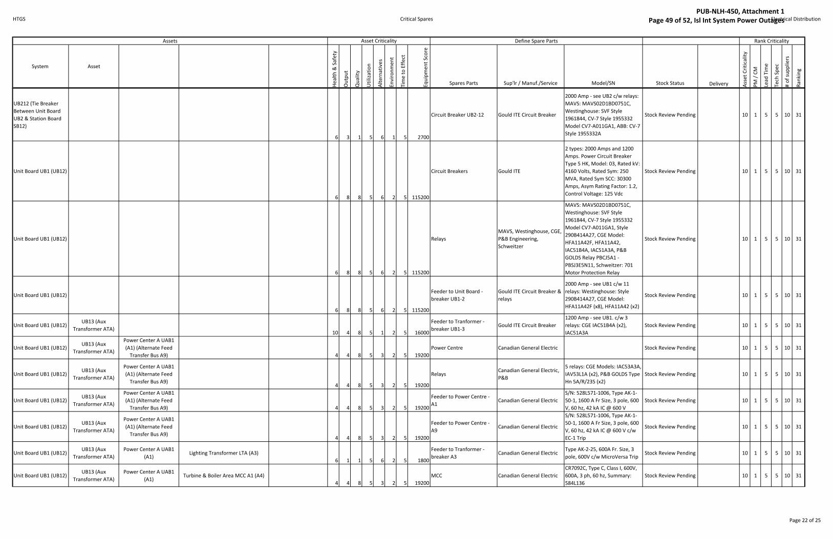
HTGS Critical Spares Electrical Distribution
System Asset
He
alt
h &
Sa
fety
Ou
tpu
t
Qu
ali
ty
Uti
liza
tio
n
Alt
ern
ati
ve
s
En
vir
on
me
nt
Tim
e t
o E
ffe
ct
Eq
uip
me
nt
Sco
re
Spares Parts Sup'lr / Manuf./Service Model/SN Stock Status Delivery Ass
et
Cri
tica
lity
PM
/ C
M
Lea
d T
ime
Te
ch S
pe
c
# o
f su
pp
lie
rs
Ra
nk
ing
Define Spare Parts Rank Criticality Asset CriticalityAssets
UB212 (Tie Breaker
Between Unit Board
UB2 & Station Board
SB12)
6 3 1 5 6 1 5 2700
Circuit Breaker UB2-12 Gould ITE Circuit Breaker
2000 Amp - see UB2 c/w relays:
MAVS: MAVS02D1BD0751C,
Westinghouse: SVF Style
1961844, CV-7 Style 1955332
Model CV7-A011GA1, ABB: CV-7
Style 1955332A
Stock Review Pending 10 1 5 5 10 31
Unit Board UB1 (UB12)
6 8 8 5 6 2 5 115200
Circuit Breakers Gould ITE
2 types: 2000 Amps and 1200
Amps. Power Circuit Breaker
Type 5 HK, Model: 03, Rated kV:
4160 Volts, Rated Sym: 250
MVA, Rated Sym SCC: 30300
Amps, Asym Rating Factor: 1.2,
Control Voltage: 125 Vdc
Stock Review Pending 10 1 5 5 10 31
Unit Board UB1 (UB12)
6 8 8 5 6 2 5 115200
Relays
MAVS, Westinghouse, CGE,
P&B Engineering,
Schweitzer
MAVS: MAVS02D1BD0751C,
Westinghouse: SVF Style
1961844, CV-7 Style 1955332
Model CV7-A011GA1, Style
290B414A27, CGE Model:
HFA11A42F, HFA11A42,
IAC51B4A, IAC51A3A, P&B
GOLDS Relay PBCJ5A1 -
PBSJ3E5N11, Schweitzer: 701
Motor Protection Relay
Stock Review Pending 10 1 5 5 10 31
Unit Board UB1 (UB12)
6 8 8 5 6 2 5 115200
Feeder to Unit Board -
breaker UB1-2
Gould ITE Circuit Breaker &
relays
2000 Amp - see UB1 c/w 11
relays: Westinghouse: Style
290B414A27, CGE Model:
HFA11A42F (x8), HFA11A42 (x2)
Stock Review Pending 10 1 5 5 10 31
Unit Board UB1 (UB12)UB13 (Aux
Transformer ATA)10 4 8 5 1 2 5 16000
Feeder to Tranformer -
breaker UB1-3Gould ITE Circuit Breaker
1200 Amp - see UB1. c/w 3
relays: CGE IAC51B4A (x2),
IAC51A3A
Stock Review Pending 10 1 5 5 10 31
Unit Board UB1 (UB12)UB13 (Aux
Transformer ATA)
Power Center A UAB1
(A1) (Alternate Feed
Transfer Bus A9) 4 4 8 5 3 2 5 19200
Power Centre Canadian General Electric Stock Review Pending 10 1 5 5 10 31
Unit Board UB1 (UB12)UB13 (Aux
Transformer ATA)
Power Center A UAB1
(A1) (Alternate Feed
Transfer Bus A9)4 4 8 5 3 2 5 19200
RelaysCanadian General Electric,
P&B
5 relays: CGE Models: IAC53A3A,
IAV53L1A (x2), P&B GOLDS Type
Hn 5A/R/235 (x2)
Stock Review Pending 10 1 5 5 10 31
Unit Board UB1 (UB12)UB13 (Aux
Transformer ATA)
Power Center A UAB1
(A1) (Alternate Feed
Transfer Bus A9) 4 4 8 5 3 2 5 19200
Feeder to Power Centre -
A1Canadian General Electric
S/N: 528L571-1006, Type AK-1-
50-1, 1600 A Fr Size, 3 pole, 600
V, 60 hz, 42 kA IC @ 600 V
Stock Review Pending 10 1 5 5 10 31
Unit Board UB1 (UB12)UB13 (Aux
Transformer ATA)
Power Center A UAB1
(A1) (Alternate Feed
Transfer Bus A9)4 4 8 5 3 2 5 19200
Feeder to Power Centre -
A9Canadian General Electric
S/N: 528L571-1006, Type AK-1-
50-1, 1600 A Fr Size, 3 pole, 600
V, 60 hz, 42 kA IC @ 600 V c/w
EC-1 Trip
Stock Review Pending 10 1 5 5 10 31
Unit Board UB1 (UB12)UB13 (Aux
Transformer ATA)
Power Center A UAB1
(A1)Lighting Transformer LTA (A3)
6 1 1 5 6 2 5 1800
Feeder to Tranformer -
breaker A3Canadian General Electric
Type AK-2-25, 600A Fr. Size, 3
pole, 600V c/w MicroVersa TripStock Review Pending 10 1 5 5 10 31
Unit Board UB1 (UB12)UB13 (Aux
Transformer ATA)
Power Center A UAB1
(A1)Turbine & Boiler Area MCC A1 (A4)
4 4 8 5 3 2 5 19200
MCC Canadian General Electric
CR7092C, Type C, Class I, 600V,
600A, 3 ph, 60 hz, Summary:
584L136
Stock Review Pending 10 1 5 5 10 31
Page 22 of 25
PUB-NLH-450, Attachment 1 Page 49 of 52, Isl Int System Power Outages
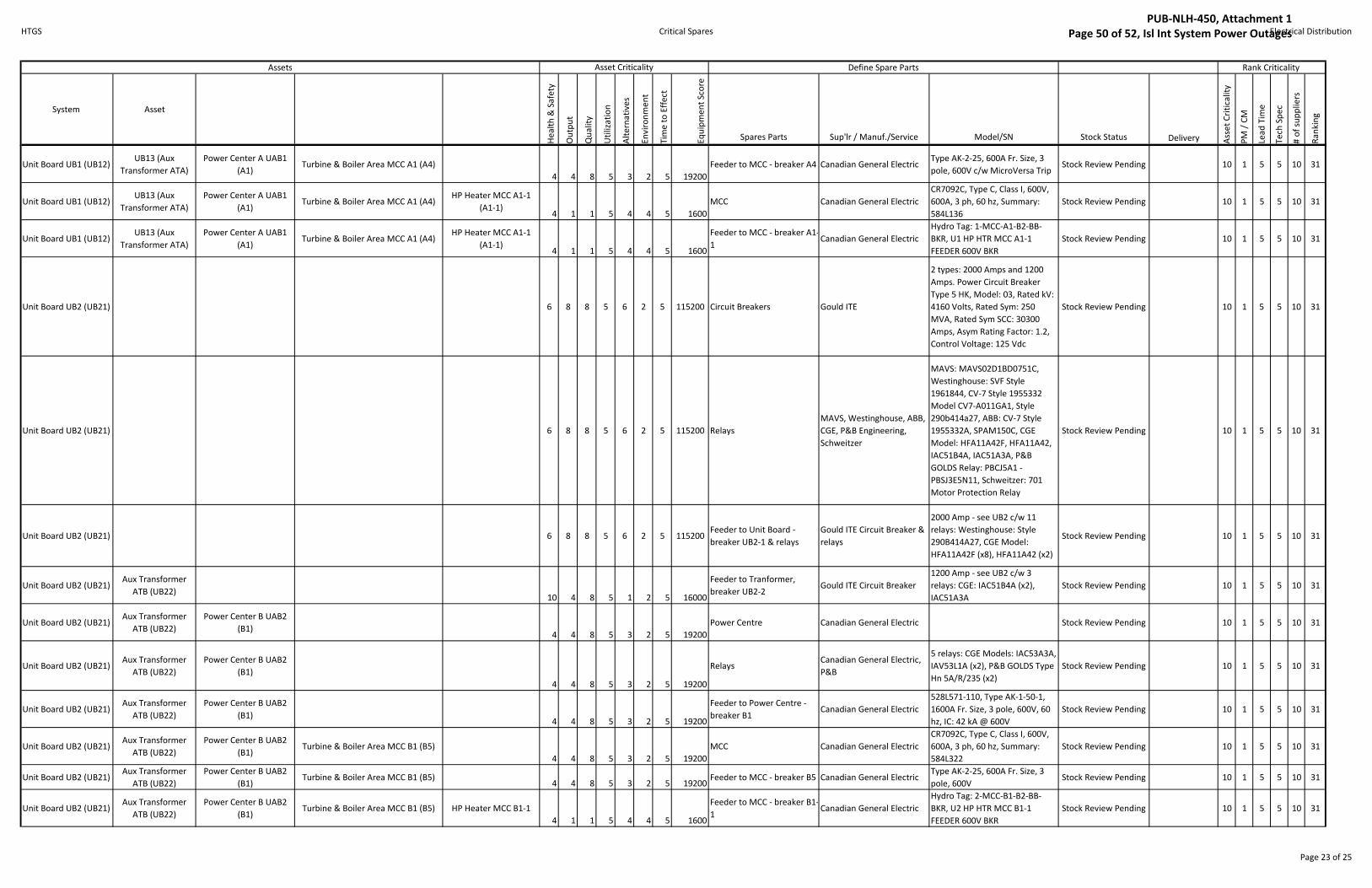
HTGS Critical Spares Electrical Distribution
System Asset
He
alt
h &
Sa
fety
Ou
tpu
t
Qu
ali
ty
Uti
liza
tio
n
Alt
ern
ati
ve
s
En
vir
on
me
nt
Tim
e t
o E
ffe
ct
Eq
uip
me
nt
Sco
re
Spares Parts Sup'lr / Manuf./Service Model/SN Stock Status Delivery Ass
et
Cri
tica
lity
PM
/ C
M
Lea
d T
ime
Te
ch S
pe
c
# o
f su
pp
lie
rs
Ra
nk
ing
Define Spare Parts Rank Criticality Asset CriticalityAssets
Unit Board UB1 (UB12)UB13 (Aux
Transformer ATA)
Power Center A UAB1
(A1)Turbine & Boiler Area MCC A1 (A4)
4 4 8 5 3 2 5 19200
Feeder to MCC - breaker A4 Canadian General ElectricType AK-2-25, 600A Fr. Size, 3
pole, 600V c/w MicroVersa TripStock Review Pending 10 1 5 5 10 31
Unit Board UB1 (UB12)UB13 (Aux
Transformer ATA)
Power Center A UAB1
(A1)Turbine & Boiler Area MCC A1 (A4)
HP Heater MCC A1-1
(A1-1)4 1 1 5 4 4 5 1600
MCC Canadian General Electric
CR7092C, Type C, Class I, 600V,
600A, 3 ph, 60 hz, Summary:
584L136
Stock Review Pending 10 1 5 5 10 31
Unit Board UB1 (UB12)UB13 (Aux
Transformer ATA)
Power Center A UAB1
(A1)Turbine & Boiler Area MCC A1 (A4)
HP Heater MCC A1-1
(A1-1)4 1 1 5 4 4 5 1600
Feeder to MCC - breaker A1-
1Canadian General Electric
Hydro Tag: 1-MCC-A1-B2-BB-
BKR, U1 HP HTR MCC A1-1
FEEDER 600V BKR
Stock Review Pending 10 1 5 5 10 31
Unit Board UB2 (UB21) 6 8 8 5 6 2 5 115200 Circuit Breakers Gould ITE
2 types: 2000 Amps and 1200
Amps. Power Circuit Breaker
Type 5 HK, Model: 03, Rated kV:
4160 Volts, Rated Sym: 250
MVA, Rated Sym SCC: 30300
Amps, Asym Rating Factor: 1.2,
Control Voltage: 125 Vdc
Stock Review Pending 10 1 5 5 10 31
Unit Board UB2 (UB21) 6 8 8 5 6 2 5 115200 Relays
MAVS, Westinghouse, ABB,
CGE, P&B Engineering,
Schweitzer
MAVS: MAVS02D1BD0751C,
Westinghouse: SVF Style
1961844, CV-7 Style 1955332
Model CV7-A011GA1, Style
290b414a27, ABB: CV-7 Style
1955332A, SPAM150C, CGE
Model: HFA11A42F, HFA11A42,
IAC51B4A, IAC51A3A, P&B
GOLDS Relay: PBCJ5A1 -
PBSJ3E5N11, Schweitzer: 701
Motor Protection Relay
Stock Review Pending 10 1 5 5 10 31
Unit Board UB2 (UB21) 6 8 8 5 6 2 5 115200Feeder to Unit Board -
breaker UB2-1 & relays
Gould ITE Circuit Breaker &
relays
2000 Amp - see UB2 c/w 11
relays: Westinghouse: Style
290B414A27, CGE Model:
HFA11A42F (x8), HFA11A42 (x2)
Stock Review Pending 10 1 5 5 10 31
Unit Board UB2 (UB21)Aux Transformer
ATB (UB22)10 4 8 5 1 2 5 16000
Feeder to Tranformer,
breaker UB2-2Gould ITE Circuit Breaker
1200 Amp - see UB2 c/w 3
relays: CGE: IAC51B4A (x2),
IAC51A3A
Stock Review Pending 10 1 5 5 10 31
Unit Board UB2 (UB21)Aux Transformer
ATB (UB22)
Power Center B UAB2
(B1)4 4 8 5 3 2 5 19200
Power Centre Canadian General Electric Stock Review Pending 10 1 5 5 10 31
Unit Board UB2 (UB21)Aux Transformer
ATB (UB22)
Power Center B UAB2
(B1)
4 4 8 5 3 2 5 19200
RelaysCanadian General Electric,
P&B
5 relays: CGE Models: IAC53A3A,
IAV53L1A (x2), P&B GOLDS Type
Hn 5A/R/235 (x2)
Stock Review Pending 10 1 5 5 10 31
Unit Board UB2 (UB21)Aux Transformer
ATB (UB22)
Power Center B UAB2
(B1)4 4 8 5 3 2 5 19200
Feeder to Power Centre -
breaker B1Canadian General Electric
528L571-110, Type AK-1-50-1,
1600A Fr. Size, 3 pole, 600V, 60
hz, IC: 42 kA @ 600V
Stock Review Pending 10 1 5 5 10 31
Unit Board UB2 (UB21)Aux Transformer
ATB (UB22)
Power Center B UAB2
(B1)Turbine & Boiler Area MCC B1 (B5)
4 4 8 5 3 2 5 19200
MCC Canadian General Electric
CR7092C, Type C, Class I, 600V,
600A, 3 ph, 60 hz, Summary:
584L322
Stock Review Pending 10 1 5 5 10 31
Unit Board UB2 (UB21)Aux Transformer
ATB (UB22)
Power Center B UAB2
(B1)Turbine & Boiler Area MCC B1 (B5)
4 4 8 5 3 2 5 19200Feeder to MCC - breaker B5 Canadian General Electric
Type AK-2-25, 600A Fr. Size, 3
pole, 600VStock Review Pending 10 1 5 5 10 31
Unit Board UB2 (UB21)Aux Transformer
ATB (UB22)
Power Center B UAB2
(B1)Turbine & Boiler Area MCC B1 (B5) HP Heater MCC B1-1
4 1 1 5 4 4 5 1600
Feeder to MCC - breaker B1-
1Canadian General Electric
Hydro Tag: 2-MCC-B1-B2-BB-
BKR, U2 HP HTR MCC B1-1
FEEDER 600V BKR
Stock Review Pending 10 1 5 5 10 31
Page 23 of 25
PUB-NLH-450, Attachment 1 Page 50 of 52, Isl Int System Power Outages
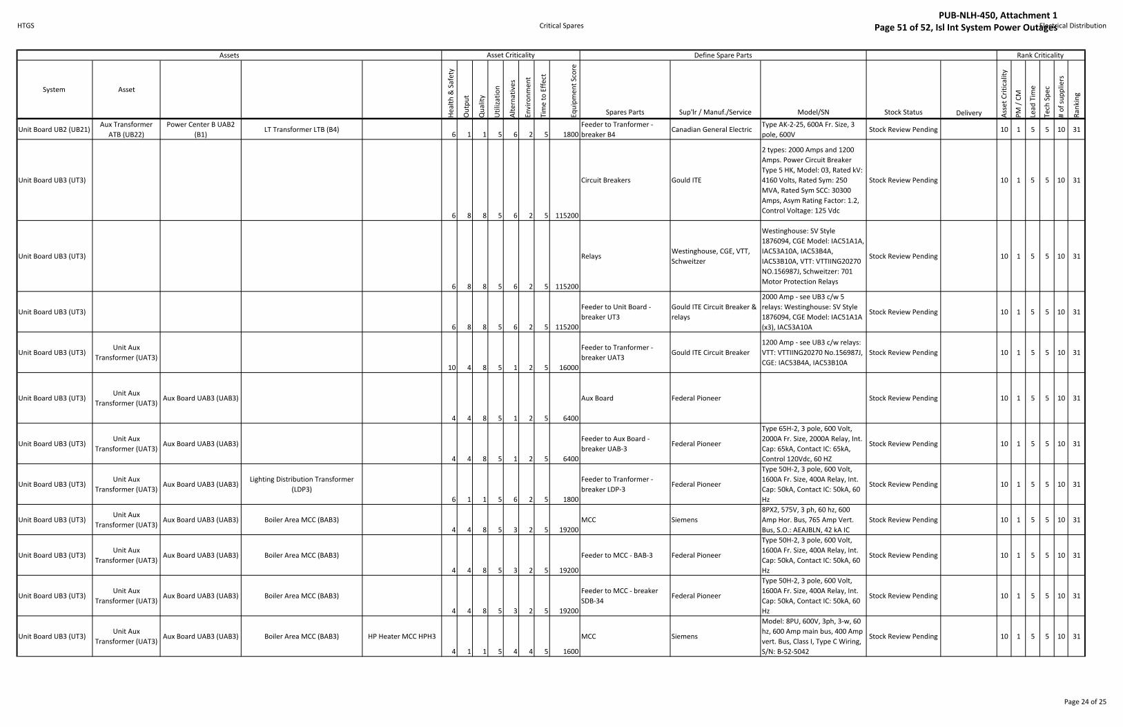
HTGS Critical Spares Electrical Distribution
System Asset
He
alt
h &
Sa
fety
Ou
tpu
t
Qu
ali
ty
Uti
liza
tio
n
Alt
ern
ati
ve
s
En
vir
on
me
nt
Tim
e t
o E
ffe
ct
Eq
uip
me
nt
Sco
re
Spares Parts Sup'lr / Manuf./Service Model/SN Stock Status Delivery Ass
et
Cri
tica
lity
PM
/ C
M
Lea
d T
ime
Te
ch S
pe
c
# o
f su
pp
lie
rs
Ra
nk
ing
Define Spare Parts Rank Criticality Asset CriticalityAssets
Unit Board UB2 (UB21)Aux Transformer
ATB (UB22)
Power Center B UAB2
(B1)LT Transformer LTB (B4)
6 1 1 5 6 2 5 1800
Feeder to Tranformer -
breaker B4Canadian General Electric
Type AK-2-25, 600A Fr. Size, 3
pole, 600VStock Review Pending 10 1 5 5 10 31
Unit Board UB3 (UT3)
6 8 8 5 6 2 5 115200
Circuit Breakers Gould ITE
2 types: 2000 Amps and 1200
Amps. Power Circuit Breaker
Type 5 HK, Model: 03, Rated kV:
4160 Volts, Rated Sym: 250
MVA, Rated Sym SCC: 30300
Amps, Asym Rating Factor: 1.2,
Control Voltage: 125 Vdc
Stock Review Pending 10 1 5 5 10 31
Unit Board UB3 (UT3)
6 8 8 5 6 2 5 115200
RelaysWestinghouse, CGE, VTT,
Schweitzer
Westinghouse: SV Style
1876094, CGE Model: IAC51A1A,
IAC53A10A, IAC53B4A,
IAC53B10A, VTT: VTTIING20270
NO.156987J, Schweitzer: 701
Motor Protection Relays
Stock Review Pending 10 1 5 5 10 31
Unit Board UB3 (UT3)
6 8 8 5 6 2 5 115200
Feeder to Unit Board -
breaker UT3
Gould ITE Circuit Breaker &
relays
2000 Amp - see UB3 c/w 5
relays: Westinghouse: SV Style
1876094, CGE Model: IAC51A1A
(x3), IAC53A10A
Stock Review Pending 10 1 5 5 10 31
Unit Board UB3 (UT3)Unit Aux
Transformer (UAT3)
10 4 8 5 1 2 5 16000
Feeder to Tranformer -
breaker UAT3Gould ITE Circuit Breaker
1200 Amp - see UB3 c/w relays:
VTT: VTTIING20270 No.156987J,
CGE: IAC53B4A, IAC53B10A
Stock Review Pending 10 1 5 5 10 31
Unit Board UB3 (UT3)Unit Aux
Transformer (UAT3)Aux Board UAB3 (UAB3)
4 4 8 5 1 2 5 6400
Aux Board Federal Pioneer Stock Review Pending 10 1 5 5 10 31
Unit Board UB3 (UT3)Unit Aux
Transformer (UAT3)Aux Board UAB3 (UAB3)
4 4 8 5 1 2 5 6400
Feeder to Aux Board -
breaker UAB-3Federal Pioneer
Type 65H-2, 3 pole, 600 Volt,
2000A Fr. Size, 2000A Relay, Int.
Cap: 65kA, Contact IC: 65kA,
Control 120Vdc, 60 HZ
Stock Review Pending 10 1 5 5 10 31
Unit Board UB3 (UT3)Unit Aux
Transformer (UAT3)Aux Board UAB3 (UAB3)
Lighting Distribution Transformer
(LDP3)
6 1 1 5 6 2 5 1800
Feeder to Tranformer -
breaker LDP-3Federal Pioneer
Type 50H-2, 3 pole, 600 Volt,
1600A Fr. Size, 400A Relay, Int.
Cap: 50kA, Contact IC: 50kA, 60
Hz
Stock Review Pending 10 1 5 5 10 31
Unit Board UB3 (UT3)Unit Aux
Transformer (UAT3)Aux Board UAB3 (UAB3) Boiler Area MCC (BAB3)
4 4 8 5 3 2 5 19200
MCC Siemens
8PX2, 575V, 3 ph, 60 hz, 600
Amp Hor. Bus, 765 Amp Vert.
Bus, S.O.: AEAJBLN, 42 kA IC
Stock Review Pending 10 1 5 5 10 31
Unit Board UB3 (UT3)Unit Aux
Transformer (UAT3)Aux Board UAB3 (UAB3) Boiler Area MCC (BAB3)
4 4 8 5 3 2 5 19200
Feeder to MCC - BAB-3 Federal Pioneer
Type 50H-2, 3 pole, 600 Volt,
1600A Fr. Size, 400A Relay, Int.
Cap: 50kA, Contact IC: 50kA, 60
Hz
Stock Review Pending 10 1 5 5 10 31
Unit Board UB3 (UT3)Unit Aux
Transformer (UAT3)Aux Board UAB3 (UAB3) Boiler Area MCC (BAB3)
4 4 8 5 3 2 5 19200
Feeder to MCC - breaker
SDB-34Federal Pioneer
Type 50H-2, 3 pole, 600 Volt,
1600A Fr. Size, 400A Relay, Int.
Cap: 50kA, Contact IC: 50kA, 60
Hz
Stock Review Pending 10 1 5 5 10 31
Unit Board UB3 (UT3)Unit Aux
Transformer (UAT3)Aux Board UAB3 (UAB3) Boiler Area MCC (BAB3) HP Heater MCC HPH3
4 1 1 5 4 4 5 1600
MCC Siemens
Model: 8PU, 600V, 3ph, 3-w, 60
hz, 600 Amp main bus, 400 Amp
vert. Bus, Class I, Type C Wiring,
S/N: B-52-5042
Stock Review Pending 10 1 5 5 10 31
Page 24 of 25
PUB-NLH-450, Attachment 1 Page 51 of 52, Isl Int System Power Outages

HTGS Critical Spares Electrical Distribution
System Asset
He
alt
h &
Sa
fety
Ou
tpu
t
Qu
ali
ty
Uti
liza
tio
n
Alt
ern
ati
ve
s
En
vir
on
me
nt
Tim
e t
o E
ffe
ct
Eq
uip
me
nt
Sco
re
Spares Parts Sup'lr / Manuf./Service Model/SN Stock Status Delivery Ass
et
Cri
tica
lity
PM
/ C
M
Lea
d T
ime
Te
ch S
pe
c
# o
f su
pp
lie
rs
Ra
nk
ing
Define Spare Parts Rank Criticality Asset CriticalityAssets
Unit Board UB3 (UT3)Unit Aux
Transformer (UAT3)Aux Board UAB3 (UAB3) Boiler Area MCC (BAB3) HP Heater MCC HPH3
4 1 1 5 4 4 5 1600
Feeder to MCC - breaker
from BAB3Siemens
Hydro Tag: 3-MCC-BAB3-F3-E-
BKR, U3 HP HTR HPH-3 600V
BKR
Stock Review Pending 10 1 5 5 10 31
Unit Board UB3 (UT3)
TB3 (Tie Breaker
Between Station
Board SB34 & Unit
Board UB3)
6 3 1 5 6 1 5 2700
Circuit Breaker TB3Gould ITE Circuit Breaker &
relays
2000 Amp - see UB3 c/w relays:
CGE: IAC51A1A, IAC53A10A,
Westinghouse: CV-7 Style
1875524 model CV7-A011BA1,
SVF-3 Style 606B321A22
Stock Review Pending 10 1 5 5 10 31
Page 25 of 25
PUB-NLH-450, Attachment 1 Page 52 of 52, Isl Int System Power Outages

FINAL REPORT, ASSET CRITICALITY ASSESSMENT and CRITICAL SPARE PARTS ANALYSIS
HARDWOODS AND STEPHENVILLE GAS TURBINE FACILITIES
Prepared for:
Newfoundland and Labrador Hydro St. John’s, NL
Prepared by: Stantec Consulting Ltd. 102-40 Highfield Park Drive Dartmouth NS B3A 0A3
Stantec Job #: 133546352_12_3
September 26, 2014
Revision Record Revision Description Prepared By Checked By Approved By
1 Update per client comments
BHM Sep 26/14
BGK Sep 26/14
2 Final Report BHW Sep 26/14
BGK Sep 26/14
PUB-NLH-450, Attachment 2 Page 1 of 75, Isl Int System Power Outages

PUB-NLH-450, Attachment 2 Page 2 of 75, Isl Int System Power Outages

FINAL REPORT, ASSET CRITICALITY ASSESSMENT AND CRITICAL SPARE PARTS ANALYSIS
ls c:\users\slamoureux\documents\bgk\nalcor\final report_bgk.docx i
Table of Contents
EXECUTIVE SUMMARY ............................................................................................................... I
1.0 INTRODUCTION ...........................................................................................................1.1 1.1 GAS TURBINE FACILITY STUDY BOUNDARIES ................................................................ 1.1 1.2 SCOPE OF WORK ........................................................................................................... 1.2 1.3 ASSET CRITICALITY ASSESSMENT ANALYSIS METHODOLOGY .................................... 1.3
2.0 GAS TURBINE FACILITIES OVERVIEW ...........................................................................2.1 2.1 HARDWOODS GAS TURBINE FACILITY .......................................................................... 2.1 2.2 STEPHENVILLE GAS TURBINE FACILITY ........................................................................... 2.2
3.0 GAS TURBINE FACILITY CRITICALITY ASSESSMENT .....................................................3.1
LIST OF APPENDICES APPENDIX A BDI Documentation APPENDIX B Photographs – Hardwoods and Stephenville Gas Turbine Facilities APPENDIX C Asset Criticality Assessment Spreadsheets
PUB-NLH-450, Attachment 2 Page 3 of 75, Isl Int System Power Outages

FINAL REPORT, ASSET CRITICALITY ASSESSMENT AND CRITICAL SPARE PARTS ANALYSIS
ls c:\users\slamoureux\documents\bgk\nalcor\final report_bgk.docx i
Executive Summary
Stantec is presenting here an Assessment of the Critical Assets comprising the Newfoundland and Labrador Hydro (“HYDRO”) Hardwoods (HWD) and Stephenville (SVL) gas turbine facilities. The gas turbines have been in service since the mid 1970’s, operating primarily as synchronous condensers providing MVAR in support of the local system voltage. While the gas turbines can provide 50 MW of emergency generation capacity, there has been very little generation provided by the units over the past 38 years.
The gas turbine facilities can only operate if all of the major systems are functioning. This study identifies the critical systems, sub-assemblies and critical mechanical components with passing reference to the associated electrical and control systems. This study is focused only upon identifying components that are site maintenance items and ranking them in terms of their criticality for preserving the availability of the gas turbine plant. Therefore the effects of ageing of the main components: gas generator, power turbine, clutch, alternator, and exciter, are not considered if the defect would call for a major plant outage.
The criticality assessment procedure used here was developed by BDI. BDI is a supplier of specialized industrial products: bearings, power transmission and fluid power. Their services include repair and inspection services and inventory management. A copy of a power-point presentation that explains their methodology was made available to Stantec, (Refer to Appendix A).
Stantec identified the systems/components comprising the gas turbine facilities, and applied a scoring system to indicate which of the systems is most critical, and lists the sub-assemblies and components included. The sub-assemblies or significant components included in each system were then assessed individually. As an outcome of this procedure, the most critical sub-assemblies/components are identified and ranked in order of criticality. The list and ranking of the components is included in Section 3.0 of this Report.
This study therefore provides a basis for starting a decision making process. Such a process is not included in the scope of this study, but is needed to identify spare parts to be readily available, their optimal location, and quantities to be available. Further work will be needed to select the spare parts that should be held by HYDRO, and those that can be acquired from other resources within an acceptable time-frame.
During the study period late June through to late September 2014, meetings were held with HYDRO officials, visits were made to each site and available HYDRO documentation was
PUB-NLH-450, Attachment 2 Page 4 of 75, Isl Int System Power Outages

FINAL REPORT, ASSET CRITICALITY ASSESSMENT AND CRITICAL SPARE PARTS ANALYSIS
ls c:\users\slamoureux\documents\bgk\nalcor\final report_bgk.docx ii
reviewed. From this information-gathering exercise Stantec obtained an appreciation of the current condition of the equipment and structures at each site sufficient to apply the criticality process to the installed systems and components. All of the many systems must be fully functional in order to operate the plant, and for most of the components there is provision for a back-up to provide for increased plant availability.
The objective of this report is to make a criticality assessment of the components comprising the two plants, and to list them in order of criticality. It is understood that this study will be followed by an assessment of the availability and readiness of the most critical systems and components that will be needed to provide the required service. Follow-up work will use the list of critical components identified in this study in order to identify where their replacements, or maintainable parts, can be located and retro-fitted within the most acceptable time-frame. The options for ownership and storage location of spare parts, demands a separate focused study.
PUB-NLH-450, Attachment 2 Page 5 of 75, Isl Int System Power Outages

FINAL REPORT, ASSET CRITICALITY ASSESSMENT AND CRITICAL SPARE PARTS ANALYSIS Introduction
September 26, 2014
ls c:\users\slamoureux\documents\bgk\nalcor\final report_bgk.docx 1.1
1.0 INTRODUCTION
This study called for an assessment of the critical assets comprising the Newfoundland and Labrador Hydro (“HYDRO”) Hardwoods (HWD) and Stephenville (SVL) gas turbine facilities. It identifies the systems comprising the Facilities, and applies a scoring system to indicate which of the systems is most critical. The sub-assemblies and components included in each system are then identified and a criticality assessment is applied to each one, and ranked in descending order of criticality.
Prior to contract award, HYDRO made Stantec aware of previous work by HYDRO for assessing the criticality of systems and assets comprising a gas turbine power plant at Happy Valley Goose Bay (HVGB) in Labrador. The methodology was originated by a contractor; BDI, and Stantec was asked to modify its offer of services to apply the HYDRO/BDI methodology to this asset criticality assessment.
BDI is a supplier of specialized industrial products: bearings, power transmission and fluid power. Their services include repair and inspection services and inventory management. A copy of a power-point presentation that explains their methodology was made available to Stantec, (Refer to Appendix A) and this together with a full day meeting with relevant HYDRO personnel brought a mutually acceptable understanding of how to interpret the BDI criticality assessment procedure.
As an outcome of this procedure, the most critical sub-assemblies/components are identified. This study therefore provides the basis for a future decision making process that identifies what should be the availability of critical spare parts, and where they should be strategically located. Further work will be needed to select the spare parts that should be held by HYDRO, and those that can be acquired within an acceptable time-frame from industrial suppliers.
HYDRO pointed out that mechanical sub-assemblies/components were to be the focus of this study. They were predicted to be the most prone to failure and likely to be high in the list of critical items that would call for the speedy replacement of parts. This study focusses upon these mechanical sub-assemblies and components with passing reference to the associated electrical and control systems.
1.1 GAS TURBINE FACILITY STUDY BOUNDARIES The study boundaries were agreed to during meetings and discussions with HYDRO. The boundaries start at the fuel-unloading facilities; they include the piping connections to the fuel storage facilities, and the fuel forwarding to the gas turbines (GT). The facilities associated with the GTs comprise: main air supply and conditioning, hot gas generator, power turbine, exhaust system, power transmission clutch arrangement, and connection to the alternator and exciter shaft systems.
PUB-NLH-450, Attachment 2 Page 6 of 75, Isl Int System Power Outages

FINAL REPORT, ASSET CRITICALITY ASSESSMENT AND CRITICAL SPARE PARTS ANALYSIS
Introduction September 26, 2014
ls c:\users\slamoureux\documents\bgk\nalcor\final report_bgk.docx 1.2
Essential auxiliary systems include: lubricating oil, shaft jacking oil, fuel pressurization and metering to the burners, combustion system, air de-icing system, alternator cooling, exciter cooling-air filtering, lubricating oil cooling, machinery containment building ventilation, and fire control system.
1.2 SCOPE OF WORK The Scope of Work identified in the Stantec Proposal dated June 13 2014 stated:
HYDRO requires a review of the spare parts stocks for both of the combustion turbine installations to make sure that the critical spares are stocked or available on a short notice to prevent the possibility of a lengthy interruption of operations during critical demand times. As a result, HYDRO has requested that Stantec conduct an assessment of critical spares for both the Stephenville and Hardwood combustion turbine installations. The objective of the study is to conduct a fundamental review of both installations with the objective of identifying all critical spare parts, sub-assemblies and components that HYDRO should carry in stock or which can be quickly sourced on short notice.
Based on their understanding of the project, Stantec proposed the following scope of work for this study:
• Review Stantec’s previous studies on the two plants, and make a preliminary list of criticalspare parts.
• Travel to Newfoundland and meet with HYDRO staff to conduct a kickoff meeting. Thekickoff meeting would serve to review the scope, budget and schedule for the project,and make sure that project objectives are aligned.
• Travel to the Hardwoods combustion turbine site and conduct a review of the existinginstallation and discuss the operation with HYDRO staff. Stantec would also use thisopportunity to collect any maintenance information and history together with anypertinent documentation to assist in the study.
• Travel to Stephenville to review a provisional list of critical spare parts and to note thedifferences between the two plants.
• Return to Stantec offices and review the HYDRO documentation for both theStephenville and Hardwoods combustion turbines. This may include the review of P&ID’s,O&M manuals, maintenance records and conducting discussions with vendors andsuppliers.
• The project deliverable is a critical spare parts list for both the Stephenville andHardwoods combustion turbine installations, based on the site visits and review of thedocumentation. The critical spare parts list will be in Excel format and will include a listingof parts and components that HYDRO should have in stock, or which can be obtainedeasily for the proper operation of both combustion turbine installations.
Prior to contract award, HYDRO made Stantec aware of previous work by HYDRO for assessing the criticality of systems and assets comprising a gas turbine power plant at Happy Valley Goose Bay (HVGB) in Labrador. The methodology was originated by a contractor; BDI, and Stantec was asked to modify its offer of services to apply the HYDRO/BDI methodology to this asset criticality assessment.
BDI is a supplier of specialized industrial products: bearings, power transmission and fluid power. Their services include repair and inspection services and inventory management. A copy of a
PUB-NLH-450, Attachment 2 Page 7 of 75, Isl Int System Power Outages
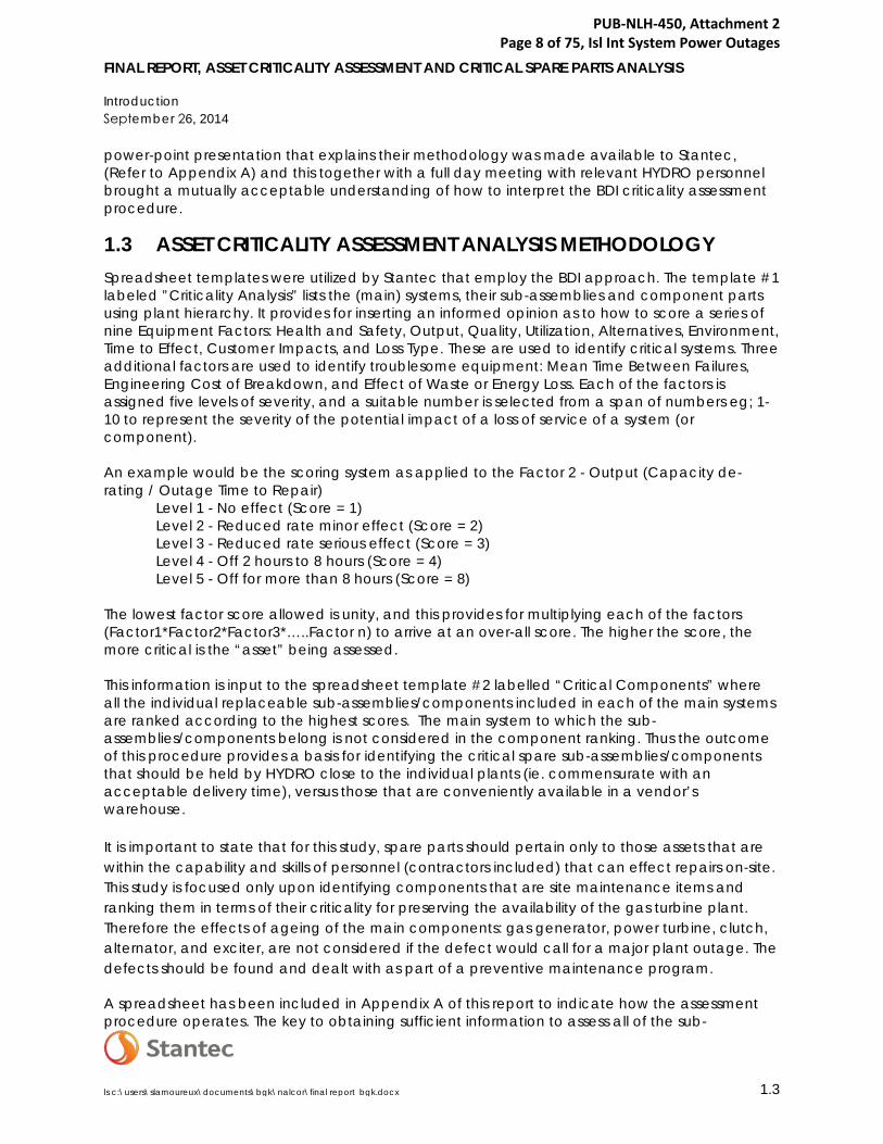
FINAL REPORT, ASSET CRITICALITY ASSESSMENT AND CRITICAL SPARE PARTS ANALYSIS
Introduction September 26, 2014
ls c:\users\slamoureux\documents\bgk\nalcor\final report_bgk.docx 1.3
power-point presentation that explains their methodology was made available to Stantec, (Refer to Appendix A) and this together with a full day meeting with relevant HYDRO personnel brought a mutually acceptable understanding of how to interpret the BDI criticality assessment procedure.
1.3 ASSET CRITICALITY ASSESSMENT ANALYSIS METHODOLOGY Spreadsheet templates were utilized by Stantec that employ the BDI approach. The template #1 labeled ”Criticality Analysis” lists the (main) systems, their sub-assemblies and component parts using plant hierarchy. It provides for inserting an informed opinion as to how to score a series of nine Equipment Factors: Health and Safety, Output, Quality, Utilization, Alternatives, Environment, Time to Effect, Customer Impacts, and Loss Type. These are used to identify critical systems. Three additional factors are used to identify troublesome equipment: Mean Time Between Failures, Engineering Cost of Breakdown, and Effect of Waste or Energy Loss. Each of the factors is assigned five levels of severity, and a suitable number is selected from a span of numbers eg; 1-10 to represent the severity of the potential impact of a loss of service of a system (or component).
An example would be the scoring system as applied to the Factor 2 - Output (Capacity de-rating / Outage Time to Repair)
Level 1 - No effect (Score = 1) Level 2 - Reduced rate minor effect (Score = 2) Level 3 - Reduced rate serious effect (Score = 3) Level 4 - Off 2 hours to 8 hours (Score = 4) Level 5 - Off for more than 8 hours (Score = 8)
The lowest factor score allowed is unity, and this provides for multiplying each of the factors (Factor1*Factor2*Factor3*…..Factor n) to arrive at an over-all score. The higher the score, the more critical is the “asset” being assessed.
This information is input to the spreadsheet template #2 labelled “Critical Components” where all the individual replaceable sub-assemblies/components included in each of the main systems are ranked according to the highest scores. The main system to which the sub-assemblies/components belong is not considered in the component ranking. Thus the outcome of this procedure provides a basis for identifying the critical spare sub-assemblies/components that should be held by HYDRO close to the individual plants (ie. commensurate with an acceptable delivery time), versus those that are conveniently available in a vendor’s warehouse.
It is important to state that for this study, spare parts should pertain only to those assets that are within the capability and skills of personnel (contractors included) that can effect repairs on-site. This study is focused only upon identifying components that are site maintenance items and ranking them in terms of their criticality for preserving the availability of the gas turbine plant. Therefore the effects of ageing of the main components: gas generator, power turbine, clutch, alternator, and exciter, are not considered if the defect would call for a major plant outage. The defects should be found and dealt with as part of a preventive maintenance program.
A spreadsheet has been included in Appendix A of this report to indicate how the assessment procedure operates. The key to obtaining sufficient information to assess all of the sub-
PUB-NLH-450, Attachment 2 Page 8 of 75, Isl Int System Power Outages

FINAL REPORT, ASSET CRITICALITY ASSESSMENT AND CRITICAL SPARE PARTS ANALYSIS
Introduction September 26, 2014
ls c:\users\slamoureux\documents\bgk\nalcor\final report_bgk.docx 1.4
assemblies and components lies in acquiring the relevant P&ID schematics. These schematics usually identify the components identification number. This will facilitate acquisition of information regarding the availability of the spare parts in appropriate quantities, and the delivery logistics to the GT facilities.
Such information needs to be correlated with the spares currently held by HYDRO and their storage location. It also calls for applying HYDRO’s expertise for the acquisition of spare parts and their supply delivery times. Insight must also be gained as to the time it may take to deliver them from current storage to where they may be needed in a hurry. This work is beyond the scope of this study.
Having categorized all the maintainable equipment, this criticality study becomes a basis for: - Prioritizing maintenance attention - Spare parts classification - Job prioritization - Agreeing priorities with production requirements.
PUB-NLH-450, Attachment 2 Page 9 of 75, Isl Int System Power Outages

FINAL REPORT, ASSET CRITICALITY ASSESSMENT AND CRITICAL SPARE PARTS ANALYSIS GAS TURBINE FACILITIES OVERVIEW
September 26, 2014
ls c:\users\slamoureux\documents\bgk\nalcor\final report_bgk.docx 2.1
2.0 GAS TURBINE FACILITIES OVERVIEW
There are companies that hold spare parts and complete Rolls Royce Olympus C gas generators in anticipation of future requirements. It is unlikely that both gas generators will become unserviceable simultaneously allowing the alternator to be operated as a synchronous condenser or at 50% MW output on either gas generator A or B.
2.1 HARDWOODS GAS TURBINE FACILITY The Hardwoods Gas Turbine Facility was placed in service in 1976 and operates as both a generator – peaking/emergency backup -- and a synchronous condenser, the latter being the dominant operating mode. The gas turbine experiences frequent start/stops, averaging over 30 starts per year. A photograph of the gas turbine facility is included in Appendix B.
The gas turbine is located within a terminal station consisting of 66 kV and 230 kV bus work, circuit-breakers, transformers, and transmission lines. The gas turbine alternator output voltage of 13.8kV is connected via enclosed bus duct to a circuit breaker located in a 13.8kV switchgear assembly. A further run of enclosed 13.8kV bus duct connects the circuit breaker to the low voltage terminals of a 13.8/66kV, 45/60/75 MVA transformer. These electrical components have not been included in this Criticality Assessment.
The facility comprises two Rolls Royce Olympus C gas generator engines (A and B) rated nominally at 25MW. They are fired on #2 diesel oil, and their hot pressurized gas is ducted to a Curtiss Wright power turbine equipped with a SSS size 208T clutch. Each gas generator engine has an air intake structure and each power turbine has an exhaust stack.
The original inlet air filter system at Hardwoods was redesigned in the early 2000s. The new filtering system consists of a monoclone pre-filter and a high efficiency second filter. This system calls for filters to be replaced when the pressure drop exceeds a certain value.
Each Curtiss Wright power turbine is a two-stage axial flow unit with the rotor assembly and main shaft supported as a cantilever by two white metal bearings housed in a pedestal. The power turbine unit is connected to the gas generator by a gas duct incorporating a bellows joint. The gas generators receive ambient air from the air inlet plenums and deliver high temperature and pressure gas to the power turbines which converts the thermal energy into rotating mechanical power. The power turbines output shaft is coupled to the alternator through SSS clutches. The turbine is connected to the exhaust system.
The snow doors on the exhaust stacks were modified from lead-screw actuation to pneumatic operation in the mid 1980s. We have no information on the compressed air supply system to the snow door operating arms, or on the spare parts that should be held on site. New expansion joints were installed in the stacks in 2004.
The oil supply to the power turbines is supplied from the alternator module main lube oil system and provides lubrication to the front and rear main radial bearings and the thrust bearing.
PUB-NLH-450, Attachment 2 Page 10 of 75, Isl Int System Power Outages

FINAL REPORT, ASSET CRITICALITY ASSESSMENT AND CRITICAL SPARE PARTS ANALYSIS
GAS TURBINE FACILITIES OVERVIEW September 26, 2014
ls c:\users\slamoureux\documents\bgk\nalcor\final report_bgk.docx 2.2
The elements that could impact on the reliability and availability of the power turbines are the blades, discs, bearings, and vibration characteristics. Historically the power turbines have provided a high level of reliability.
A 53MW 13.8kV Brush alternator frame BDAX8-280 is common to and driven by either or both power turbines as required. The alternator has a rotating exciter connected to the shaft. Generator air cooling is provided by fan blades on the alternator shaft that induces filtered external ambient air through the stator and rotor.
The main lube oil system is common to each power turbine, clutch and the alternator/exciter. Lube oil cooling is provided by an external glycol cooler that is located outdoors. A single glycol circulation pump and three-way temperature control valve are located in the auxiliary module building which is dedicated to the main lube oil storage and pump facilities. The Rolls Royce gas generators each have their own lube oil systems.
Air compressors for starting air and process purposes are also located within the auxiliary module building in an enclosed room. Air receiver tanks are located outside the building.
The fuel oil system consists of a truck unloading facility that can be connected to pump sets in a building located near the storage tank area. Fuel is fed to a single storage tank of 14,000bbl (2,225,000L) nominal capacity. A piping system connects between the storage tank and fuel forwarding pump sets (AC and DC motor) located in a dedicated fuel forwarding building adjacent to the gas turbine.
2.2 STEPHENVILLE GAS TURBINE FACILITY The Stephenville Gas Turbine Facility was placed in service in 1975 and is a sister unit to the gas turbine at Hardwoods. Like Hardwoods, the Stephenville Gas Turbine operates as both a generator – peaking/emergency backup -- and a synchronous condenser, the latter being the dominant operating mode. Based on information provided by HYDRO, the gas turbine, while having minimal running time, has experienced an average of 14 starts per year over its 39 years of service. A photograph of the gas turbine facility is included in Appendix B.
The facility consists of two Rolls Royce Olympus C, 25MW gas generator engines (A and B) fired on #2 diesel oil, each driving a Curtiss Wright power turbine equipped with a SSS size 208T clutch. Each gas generator engine has an air intake structure and each power turbine has an exhaust stack. It is our understanding both exhaust stacks at Stephenville were replaced in 1992.
The fuel oil system consists of a truck unloading facility; three storage tanks, each of 477,000L nominal capacity and fuel unloading and forwarding pump sets located in a fuel forwarding building. Air compressors for starting air and process purposes are located within the control building in an enclosed room.
A 53MW 13.8 kV Brush alternator frame BDAX8-280 is common to and driven by each power turbine. The alternator has a rotating exciter connected to the shaft. The lube oil system is common to each power turbine, clutch and the alternator. Lube oil cooling is provided by an external glycol cooler. Generator air cooling is provided by an internal air heat exchanger and an external glycol cooler. The two glycol coolers and pump sets are located outdoors.
PUB-NLH-450, Attachment 2 Page 11 of 75, Isl Int System Power Outages

FINAL REPORT, ASSET CRITICALITY ASSESSMENT AND CRITICAL SPARE PARTS ANALYSIS
GAS TURBINE FACILITIES OVERVIEW September 26, 2014
ls c:\users\slamoureux\documents\bgk\nalcor\final report_bgk.docx 2.3
While the alternators at Stephenville and Hardwoods are similar in terms of MW output and construction, they do have major differences that preclude a possible re-location from one site to another.
• The Stephenville alternator cooling system uses a 50/50 glycol-water mixture to absorbheat from the air circulating inside the alternator casing and discharges the heat toambient air by means of an external heat exchanger complete with fan cooling. TheHardwoods alternator cooling does not use an external heat exchanger. TheHardwoods cooling system consists of intake filters and discharge louvers located on thealternator enclosure. The clean air is induced into the alternator by fan blades mountedon the alternator main shaft, and is rejected from the system via exhaust louvers.
• The Stephenville alternator rotor is 1.64 meters longer than the rotor length at theHardwoods site.
The gas turbine plant is located within a terminal station consisting of 66kV and 230kV bus work, circuit breakers, transformers and transmission lines. The gas turbine alternator output voltage of 13.8kV is connected via an enclosed bus duct to a circuit breaker located in a 13.8kV switchgear assembly. A further run of enclosed 13.8kV bus duct connects the circuit breaker to the low voltage terminals of a 13.8/66kV, 45/60/75MVA transformer.
Electrical equipment consists of a 13.8kV switchgear assembly located in an outdoor enclosure; enclosed bus duct connecting the alternator to its circuit breaker and 13.8/66kV step-up transformer. Motor control centres (AC and DC), as well as 250V and 125V DC batteries, battery chargers and inverter are all located in the control building.
An ELSAG Bailey INFI 90 DCS system installed in 1999 and located in the control building provides the local human machine interface (HMI) and the control and monitoring functions for the facility. The gas turbine is also remotely started/stopped and monitored from the Energy Control Centre located in St. John’s via a SCADA system.
PUB-NLH-450, Attachment 2 Page 12 of 75, Isl Int System Power Outages

FINAL REPORT, ASSET CRITICALITY ASSESSMENT AND CRITICAL SPARE PARTS ANALYSIS GAS TURBINE FACILITY CRITICALITY ASSESSMENT
September 26, 2014
ls c:\users\slamoureux\documents\bgk\nalcor\final report_bgk.docx 3.1
3.0 GAS TURBINE FACILITY CRITICALITY ASSESSMENT Sub-section 1.3 provides a description of the methodology used to assess the criticality of the systems, sub-systems, and components comprising the gas turbine power plant facilities. This Section 3.0 identifies the recommended critical components suggested for stock and the recommended storage location, with passing reference to the associated electrical and control systems. It is important to remember that for this study, spare parts should only pertain to those assets that are within the capability and skills of personnel (contractors included) that can effect repairs on-site.
In the following table, recommended spare critical components are listed with a recommended location for storage. These items have been determined to be necessary based on their level of criticality, likelihood of failure and component approximate cost. The spreadsheets that provided the input into the final ranking table are contained in Appendix C.
It is important to note that the spare parts model numbers must be correlated with the gas generator model numbers. It is recommended that a list of gas generators and their current location should be compiled and checks made to verify that the recommended spares are located appropriately.
Critical Components Stocked Spare Item Combustion Chamber, Gas Generator, Prime Mover Systems Both Sites (one set per site) Liquid Fuel Burner - Complete (BDC.3026), Gas Generator, Prime Mover Systems Both Sites (one set per site) Lower Fuel Pump Assembly, Gas Generator, Prime Mover Systems Both Sites Oil Pump - Complete, Gas Generator, Prime Mover Systems Both Sites Outer Fuel Pump Drive Assembly (BDA.7591), Gas Generator, Prime Mover Systems Both Sites Outer Oil Pump Drive Assembly (47-1-1-006409), Gas Generator, Prime Mover Systems Both Sites Outer Starter Drive Assembly (BDA.1153), Gas Generator, Prime Mover Systems Both Sites Scavenge Pump Assembly (47-1-1-006418), Gas Generator, Prime Mover Systems Both Sites Upper Fuel Pump Assembly, Gas Generator, Prime Mover Systems Both Sites High Energy Ignition Unit, Gas Generator, Prime Mover Systems Both Sites Anti-Icing Hot Air Valve - Complete (810-501-0747), Gas Generator, Prime Mover Systems Both Sites Fire Fuel Shutoff Valve (LF-8), Liquid Fuel System, Auxiliary Systems Both Sites Exciter Bearing, 63MVA 50MW Generator, Power Generation Systems Both Sites Rotor Bearing, 63MVA 50MW Generator, Power Generation Systems Both Sites Bearing (181413 or 181332), Power Turbine Model CT2, Prime Mover Systems Both Sites Bearing (494047), Power Turbine Model CT2, Prime Mover Systems Both Sites Bearing (494056), Power Turbine Model CT2, Prime Mover Systems Both Sites HP Compressor Magnetic Pickup, Gas Generator, Prime Mover Systems Both Sites LP Compressor Magnetic Pickup, Gas Generator, Prime Mover Systems Both Sites Vibration Transducer, Gas Generator, Prime Mover Systems Both Sites (one per engine) Jacking Oil Pump, Main Lube Oil System, Auxiliary Systems Both Sites Oil to Glycol Heat Exchanger (CLR-LO-1), MLO/Glycol Cooling System, Auxiliary Systems Both Sites Fuel Filter, Gas Generator, Prime Mover Systems Both Sites (Filter Consumables Only) Oil Filter Unit - Complete (B.108506), Gas Generator, Prime Mover Systems Both Sites (Filter Consumables Only) Filter (494064), Power Turbine Model CT2, Prime Mover Systems Both Sites (Filter Consumables Only) Proximity Switch, Clutch, Prime Mover Systems Both Sites (one per clutch)
PUB-NLH-450, Attachment 2 Page 13 of 75, Isl Int System Power Outages

FINAL REPORT, ASSET CRITICALITY ASSESSMENT AND CRITICAL SPARE PARTS ANALYSIS GAS TURBINE FACILITY CRITICALITY ASSESSMENT
September 26, 2014
ls c:\users\slamoureux\documents\bgk\nalcor\final report_bgk.docx 3.2
Actuator - Hydraulic & DC Motor (A-LF-1), Liquid Fuel System, Auxiliary Systems Both Sites Altair Quick Shutoff Valve (AV-LF-1), Liquid Fuel System, Auxiliary Systems Both Sites Fuel Valve (FC-LF-1), Liquid Fuel System, Auxiliary Systems Both Sites Supplemental Fuel AC Pump (P&MLF-5), Liquid Fuel System, Auxiliary Systems Both Sites Fuel Pump Servo Valve (SV-LF-1), Liquid Fuel System, Auxiliary Systems Both Sites Fuel Recirculation Solenoid Valve (LF-7), Liquid Fuel System, Auxiliary Systems Both Sites Fuel Regulator (LF-4), Liquid Fuel System, Auxiliary Systems Both Sites Forwarding DC Emergency Pump No 2, Liquid Fuel System, Auxiliary Systems, SVL GT Stephenville Only Jacking Oil Permissive Pressure Switch, Main Lube Oil System, Auxiliary Systems Both Sites Low Trip Pressure Switch (PS-LO-7), Main Lube Oil System, Auxiliary Systems Both Sites Start Permissive Pressure Switch (PS-LO-6), Main Lube Oil System, Auxiliary Systems, SVL GT Stephenville Only Clutch Control Solenoid Valve (LO-6), Main Lube Oil System, Auxiliary Systems, HWD GT Hardwoods Only Valve (181536), Power Turbine Model CT2, Prime Mover Systems Bishop's Falls Primary Ratchet Ring, Clutch, Prime Mover Systems Bishop's Falls Secondary Ratchet Ring, Clutch, Prime Mover Systems Bishop's Falls Primary Pawl Spring, Clutch, Prime Mover Systems Both Sites Primary Pawl, Clutch, Prime Mover Systems Both Sites Secondary Pawl, Clutch, Prime Mover Systems Both Sites Pressure Switch, Permissive Start - Low Pressure Alarm (PS-LF-2), Liquid Fuel System, Auxiliary Systems Both Sites Pressure Switch, Trip - Low Fuel Pressure (PS-LF-3), Liquid Fuel System, Auxiliary Systems Both Sites Supplemental Fuel Filter (F-LF-5), Liquid Fuel System, Auxiliary Systems Both Sites (Filter Consumables Only) Double-Acting Pneumatic Cylinder, Snow Door Assembly, Exhaust, Prime Mover Systems, SVL GT Stephenville Only Limit Switch, Snow Door Assembly, Exhaust, Prime Mover Systems, SVL GT Stephenville Only Pneumatic Cylinder, Snow Door Assembly, Exhaust, Prime Mover Systems, HWD GT Hardwoods Only Proximity Switch, Snow Door Assembly, Exhaust, Prime Mover Systems, HWD GT Hardwoods Only NC Solenoid Valve (SV-CA-2), Gas Generator Air Starter System, Auxiliary Systems Both Sites NO Solenoid Valve (SV-CA-1), Gas Generator Air Starter System, Auxiliary Systems Both Sites Starter Control Valve (CA-17), Gas Generator Air Starter System, Auxiliary Systems Both Sites Battery, 125 VDC Battery Bank, D.C. Electrical System, Power Generation Systems, HWD GT Hardwoods Only Battery, 250 VDC Battery Bank, D.C. Electrical System, Power Generation Systems, SVL GT Stephenville Only Gas Generator Permissive Start Pressure Switch, Gas Generator Air Starter System, Auxiliary Systems Both Sites
Starter Overpressure Pressure Switch (PS-CA-3), Gas Generator Air Starter System, Auxiliary Systems Both Sites 3-Way Thermostatic Valve (GL-2), MLO/Glycol Cooling System, Auxiliary Systems Both Sites Thermocouple (181398N1), Power Turbine Model CT2, Prime Mover Systems Both Sites Speed Pickup (181487), Power Turbine Model CT2, Prime Mover Systems Both Sites Vibration Pickup (181571), Power Turbine Model CT2, Prime Mover Systems Both Sites Thermocouple (181397), Power Turbine Model CT2, Prime Mover Systems Both Sites Thermocouple (181398N2), Power Turbine Model CT2, Prime Mover Systems Both Sites 3-Way Thermostatic Valve (GA-9), Alternator Cooling System, Auxiliary Systems, SVL GT Stephenville Only Probe (181414N1), Power Turbine Model CT2, Prime Mover Systems Both Sites Probe (181414N2), Power Turbine Model CT2, Prime Mover Systems Both Sites Thermocouple (184847), Power Turbine Model CT2, Prime Mover Systems Both Sites Motor Operated Tank Shutoff Valve (LF-38), Liquid Fuel System, Auxiliary Systems, HWD GT Hardwoods Only Final Fuel Filter (F-LF-1), Liquid Fuel System, Auxiliary Systems Both Sites (Filter Consumables Only) Heater Filter Coalescer, Liquid Fuel System, Auxiliary Systems Both Sites (Filter Consumables Only) Prefilter, Liquid Fuel System, Auxiliary Systems Both Sites (Filter Consumables Only) Low Oil Pressure Switch (PS-GGLO-1), Gas Generator Lube Oil System, Auxiliary Systems Both Sites
PUB-NLH-450, Attachment 2 Page 14 of 75, Isl Int System Power Outages

FINAL REPORT, ASSET CRITICALITY ASSESSMENT AND CRITICAL SPARE PARTS ANALYSIS GAS TURBINE FACILITY CRITICALITY ASSESSMENT
September 26, 2014
ls c:\users\slamoureux\documents\bgk\nalcor\final report_bgk.docx 3.3
High Efficiency Farr HP-100 Filter (2'x2'x2"), Filter Box - Curtiss Wright, Prime Mover Systems Both Sites (Filter Consumables Only) Expansion Tank Low Level Alarm (LL-GA-1), Alternator Cooling System, Auxiliary Systems, SVL GT Stephenville Only Low Liquid Level Alarm Switch (LL-GL-1), MLO/Glycol Cooling System, Auxiliary Systems Bishop's Falls Pressure Regulating Valve (LO-8), Main Lube Oil System, Auxiliary Systems Both Sites Inertial Filter Element, Filter Box - Curtiss Wright, Prime Mover Systems Both Sites (Filter Consumables Only) Filter (F-GGLO-1), Gas Generator Lube Oil System, Auxiliary Systems Both Sites (Filter Consumables Only)
Unloading Filter, Liquid Fuel System, Auxiliary Systems, SVL GT Stephenville Only (Filter Consumables
Only) Level Switch (LS-GGLO-1), Gas Generator Lube Oil System, Auxiliary Systems Bishop's Falls Duplex 25u Filter (F-LO-1), Main Lube Oil System, Auxiliary Systems Both Sites (Filter Consumables Only) Hydraulic Actuator Supply Filter (F-HO-1), Liquid Fuel System, Auxiliary Systems Both Sites (Filter Consumables Only) Filter/Coalescer Heater (HTR-LF-1), Liquid Fuel System, Auxiliary Systems, HWD GT Hardwoods Only Filter Differential Pressure Switch (PSD-LO-1), Main Lube Oil System, Auxiliary Systems Bishop's Falls
Filter Upstream Pressure Switch (PS-GGLO-3), Gas Generator Lube Oil System, Auxiliary Systems Bishop's Falls
Heater Control Temperature Switch (TS-GGLO-1), Gas Generator Lube Oil System, Auxiliary Systems Bishop's Falls Heater Control Temperature Switch (TS-LO-1), Main Lube Oil System, Auxiliary Systems Bishop's Falls Final Fuel Filter Differential Pressure Switch (PSD-LF-1), Liquid Fuel System, Auxiliary Systems Bishop's Falls
Oil to Clutch A Pressure Transducer (PT-LO-1), Main Lube Oil System, Auxiliary Systems, SVL GT Stephenville Only Oil to Clutch B Pressure Transducer (PT-LO-2), Main Lube Oil System, Auxiliary Systems, SVL GT Stephenville Only
Pre-filter Differential Pressure Switch (PSD-LF-2), Liquid Fuel System, Auxiliary Systems, HWD GT Bishop's Falls AC Pump Discharge Fuel Pressure Switch (PS-LF-4), Liquid Fuel System, Auxiliary Systems, HWD GT Hardwoods Only DC Pump Start Pressure Switch (PS-LO-1), Main Lube Oil System, Auxiliary Systems, SVL GT Stephenville Only DC Pump Start Pressure Switch (PS-LO-2), Main Lube Oil System, Auxiliary Systems, SVL GT Stephenville Only DC Pump Start Pressure Switch (PS-LO-3), Main Lube Oil System, Auxiliary Systems, HWD GT Hardwoods Only Fuel Pressure Transducer (PT-LF-1), Liquid Fuel System, Auxiliary Systems Bishop's Falls Low Oil Pressure Switch (PS-GGLO-2), Gas Generator Lube Oil System, Auxiliary Systems Bishop's Falls P3 Pressure Transducer (PT-P3-1), Liquid Fuel System, Auxiliary Systems Bishop's Falls Pressure Switch (PS-HO-1), Liquid Fuel System, Auxiliary Systems Bishop's Falls
Common Drain Clutch A Thermocouple (TC-LO-3), Main Lube Oil System, Auxiliary Systems, SVL GT Stephenville Only Fuel Supply Thermocouple (TC-LF-1), Liquid Fuel System, Auxiliary Systems, SVL GT Stephenville Only Fuel Supply Thermocouple (TC-LF-1), Liquid Fuel System, Auxiliary Systems, SVL GT Stephenville Only NC Solenoid Valve (SV-CA-3), Gas Generator Air Starter System, Auxiliary Systems Bishop's Falls
Alternator Bearing Drain Oil Thermocouple (TC-LO-3), Main Lube Oil System, Auxiliary Systems, HWD GT Hardwoods Only
Alternator Cooling Air Temperature Thermocouple (TC-A-1), Alternator Cooling System, Auxiliary Systems, SVL GT Stephenville Only Common Drain Clutch B Thermocouple (TC-LO-11), Main Lube Oil System, Auxiliary Systems, SVL GT Stephenville Only Compressor Start-Stop Pressure Switch (PS-CA-1), Gas Generator Air Starter System, Auxiliary Systems Bishop's Falls Compressor Start-Stop Pressure Switch (PS-CA-2), Gas Generator Air Starter System, Auxiliary Bishop's Falls
PUB-NLH-450, Attachment 2 Page 15 of 75, Isl Int System Power Outages

FINAL REPORT, ASSET CRITICALITY ASSESSMENT AND CRITICAL SPARE PARTS ANALYSIS GAS TURBINE FACILITY CRITICALITY ASSESSMENT
September 26, 2014
ls c:\users\slamoureux\documents\bgk\nalcor\final report_bgk.docx 3.4
Systems
Fuel Temperature Sensor (TS-LF-1), Liquid Fuel System, Auxiliary Systems Bishop's Falls
Oil Drain Alternator Clutch Bearing 1 Thermocouple (TC-LO-4), Main Lube Oil System, Auxiliary Systems, SVL GT Stephenville Only Oil Drain Alternator Clutch Bearing 2 Thermocouple (TC-LO-5), Main Lube Oil System, Auxiliary Systems, SVL GT Stephenville Only
Oil Drain Alternator Clutch Bearing 3 Thermocouple (TC-LO-6), Main Lube Oil System, Auxiliary Systems, SVL GT Stephenville Only Oil Drain Alternator Clutch Bearing 4 Thermocouple (TC-LO-7), Main Lube Oil System, Auxiliary Systems, SVL GT Stephenville Only Oil Drain Alternator Clutch Bearing 5 Thermocouple (TC-LO-8), Main Lube Oil System, Auxiliary Systems, SVL GT Stephenville Only Oil Drain Alternator Clutch Bearing 6 Thermocouple (TC-LO-9), Main Lube Oil System, Auxiliary Systems, SVL GT Stephenville Only Oil Drain Exciter Bearing 7 Thermocouple (TC-LO-10), Main Lube Oil System, Auxiliary Systems, SVL GT Stephenville Only Oil Drain Thermocouple (TC-LO-2), Main Lube Oil System, Auxiliary Systems, HWD GT Hardwoods Only Oil Supply Thermocouple (TC-GGLO-1), Gas Generator Lube Oil System, Auxiliary Systems Bishop's Falls Oil Supply Thermocouple (TC-LO-1), Main Lube Oil System, Auxiliary Systems Bishop's Falls Inlet Pressure Transducer, Gas Generator Enclosure with Septum Doors, Prime Mover Systems Bishop's Falls
Inlet Temperature Thermocouple, Gas Generator Enclosure with Septum Doors, Prime Mover Systems Bishop's Falls Resistance Temperature Detector Probe, Gas Generator Enclosure with Septum Doors, Prime Mover Systems Bishop's Falls
PUB-NLH-450, Attachment 2 Page 16 of 75, Isl Int System Power Outages

FINAL REPORT, ASSET CRITICALITY ASSESSMENT AND CRITICAL SPARE PARTS ANALYSIS Appendix A BDI Documentation
September 26, 2014
ls c:\users\slamoureux\documents\bgk\nalcor\final report_bgk.docx A.1
BDI DOCUMENTATION Appendix A
A.1 BDI ASSET CRITICALITY ASSESSMENT METHODOLOGY
PUB-NLH-450, Attachment 2 Page 17 of 75, Isl Int System Power Outages

PUB-NLH-450, Attachment 2 Page 18 of 75, Isl Int System Power Outages

Asset Criticality
www.bdiworldwide.com
December 05, 2012
PUB-NLH-450, Attachment 2 Page 19 of 75, Isl Int System Power Outages

Workshop Session - Content
Criticality Overview
Criticality Pilot Working Session
• Criticality Assessment Guide Review (Sheet A)
• Criticality Equipment/Additional Factor Review (Sheet B)
• Criticality Analysis Template Review (Sheet C)
Critical Spares Process Review (Sheet C)
Criticality Self Assessment Review (Sheet D)
Criticality Self Assessment Example Pilot Session
www.bdiworldwide.com
PUB-NLH-450, Attachment 2 Page 20 of 75, Isl Int System Power Outages

Criticality
• Process of ranking and identifying specific physical assets that are most critical to achieving defined business goals.
These common Business Goals to include: • Safety • Environment • Throughput • Quality • Customer Service • Operating Costs
www.bdiworldwide.com 3
PUB-NLH-450, Attachment 2 Page 21 of 75, Isl Int System Power Outages

Criticality Steps
A. Criticality Analysis Steps/Instructions B. Criticality Analysis Template and Factors
Definitions C. Critical Asset Listing D. Criticality Self-Assessment
1. Instructions (How to Conduct Assessment) 2. Self-Assessment Template (Questionnaire) 3. Critical Asset Audit Summary (Gaps &
Opportunities) 4. Spider Diagram & Action Plan
www.bdiworldwide.com
PUB-NLH-450, Attachment 2 Page 22 of 75, Isl Int System Power Outages

Criticality Step 1
• A team is assembled from Operations and
Maintenance/Engineering • Ideally consisting of:
– Operators – Mechanics – Electricians – Supporting Safety/QA Staff
• The team should be led by the Maintenance Manager or Plant Engineer
• The exercise and results should have support of the Production and Plant Manager
www.bdiworldwide.com
PUB-NLH-450, Attachment 2 Page 23 of 75, Isl Int System Power Outages

Criticality Step 2
• Review Equipment Criticality Assessment Guide • Review the two groups of Criticality Analysis
factors to be used – Equipment Factors – used to identify critical equipment
• Safety, Output, Quality, Utilization, Alternatives, Environment, Time to Effect
– Additional Factors – used to identify troublesome equipment
• Mean Time Between Failures, Engineering Cost of Breakdown, Effect of Waste or Energy Loss
www.bdiworldwide.com
PUB-NLH-450, Attachment 2 Page 24 of 75, Isl Int System Power Outages

Criticality Step 2 Example
EquipmentNumber Equipment Name Fa
ctor
1H
ealth
& S
afet
y
Fact
or 2
Out
put/T
hrou
ghpu
t
Fact
or 3
Qua
lity
Fact
or 4
Util
izat
ion
Fact
or 5
A
ltern
ativ
es
Fact
or 6
Env
iron
men
t
Fact
or 7
Tim
e to
Eff
ect
Equ
ipm
ent
Sco
re
Fact
or 8
MTB
F
Fact
or 9
Eng
inee
ring
Cos
t B
reak
dow
n
Fact
or 1
0E
ffec
t of W
aste
or
Ene
rgy
Loss
Add
ition
alFa
ctor
sc
Cri
tical
ityS
core
M-107-041 MOTORMotor-Recirc Pump-#2 Preheater
www.bdiworldwide.com
PUB-NLH-450, Attachment 2 Page 25 of 75, Isl Int System Power Outages

Criticality Step 3
• Definitions of four or five levels for each factor
are agreed. The greater the impact, the higher the level score e.g. Health & Safety, – No risk of injury - level 1 – Risk of death - level 4
• Populate the Criticality Analysis template with plant hierarchy equipment
• Enter the factor scores for each piece of equipment into the analysis template
8 www.bdiworldwide.com
PUB-NLH-450, Attachment 2 Page 26 of 75, Isl Int System Power Outages
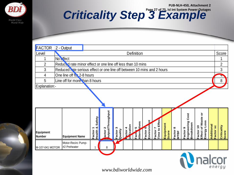
Criticality Step 3 Example
EquipmentNumber Equipment Name F
acto
r 1
Hea
lth
& S
afet
y
Fac
tor
2O
utp
ut/
Th
rou
gh
pu
t
Fac
tor
3Q
ual
ity
Fac
tor
4U
tiliz
atio
n
Fac
tor
5 A
lter
nat
ives
Fac
tor
6E
nvi
ron
men
t
Fac
tor
7T
ime
to E
ffec
t
Eq
uip
men
tS
core
Fac
tor
8M
TB
F
Fac
tor
9E
ng
inee
rin
g C
ost
B
reak
do
wn
Fac
tor
10E
ffec
t o
f W
aste
or
En
erg
y L
oss
Ad
dit
ion
alF
acto
r sc
Cri
tica
lity
Sco
re
M-107-041 MOTORMotor-Recirc Pump-#2 Preheater 1 8
FACTOR 2 - OutputLevel Definition Score
1 No effect 12 Reduced rate minor effect or one line off less than 10 mins 23 Reduced rate serious effect or one line off between 10 mins and 2 hours 34 One line off for 2-8 hours 45 Line off for more than 8 hours 8
Explanation:-
www.bdiworldwide.com
PUB-NLH-450, Attachment 2 Page 27 of 75, Isl Int System Power Outages

Criticality Step 4 - Scoring System
Factor 1 Score x Factor 2 Score x etc. = Equipment Score Factor 8 Score x Factor 9 Score x etc. = Additional Score Equipment Score x Additional Factor Score = Total Score
• The equipment criticality score is almost independent of
the additional factor score. • It can change when there is a significant change in plant
requirements, safety aspects or the process change
www.bdiworldwide.com 10
PUB-NLH-450, Attachment 2 Page 28 of 75, Isl Int System Power Outages
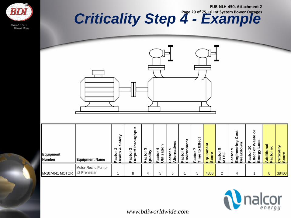
Criticality Step 4 - Example
EquipmentNumber Equipment Name Fa
ctor
1H
ealth
& S
afet
y
Fact
or 2
Out
put/T
hrou
ghpu
t
Fact
or 3
Qua
lity
Fact
or 4
Util
izat
ion
Fact
or 5
A
ltern
ativ
es
Fact
or 6
Env
iron
men
t
Fact
or 7
Tim
e to
Eff
ect
Equ
ipm
ent
Sco
re
Fact
or 8
MTB
F
Fact
or 9
Eng
inee
ring
Cos
t B
reak
dow
n
Fact
or 1
0E
ffec
t of W
aste
or
Ene
rgy
Loss
Add
ition
alFa
ctor
sc
Cri
tical
ityS
core
M-107-041 MOTORMotor-Recirc Pump-#2 Preheater 1 8 4 5 6 1 5 4800 2 4 1 8 38400
www.bdiworldwide.com
PUB-NLH-450, Attachment 2 Page 29 of 75, Isl Int System Power Outages

Criticality Step 5 - Classification of Criticality
• The results of the criticality analysis are examined to identify clusters of numbers
• Having categorized all maintainable equipment this study becomes the basis for: – prioritizing maintenance attention – spare parts classification – job prioritization – agreeing priorities with production
www.bdiworldwide.com 12
PUB-NLH-450, Attachment 2 Page 30 of 75, Isl Int System Power Outages

Criticality Step 6 - Determination of Criticality Breakpoints
www.bdiworldwide.com 13
PUB-NLH-450, Attachment 2 Page 31 of 75, Isl Int System Power Outages

Criticality Step 8 - The Most Critical Assets
• Having rated the plant equipment, the ones that are the most important are then subjected to further analysis to determine the best type of maintenance
• Failure Modes Effects Analysis (FMEA) is the techniques used most often. This is typically done by the engineering department
www.bdiworldwide.com 14
PUB-NLH-450, Attachment 2 Page 32 of 75, Isl Int System Power Outages
Criticality Step 9 - Medium and Low Assets
• Manufacturers data, user experience and common sense are used to determine the best maintenance type for the medium critical equipment
• The lowest critical equipment is often either operated to failure or given simple cleaning and lubrication schedules
www.bdiworldwide.com
PUB-NLH-450, Attachment 2 Page 33 of 75, Isl Int System Power Outages

Summary
• Introduction to Criticality Reviewed
• Criticality Analysis Steps Reviewed
Any questions so far?
www.bdiworldwide.com
PUB-NLH-450, Attachment 2 Page 34 of 75, Isl Int System Power Outages

Next – Workshop Session
• Rank Your Critical Equipment • Criticality Assessment Guide review • Equipment Factors review • Additional Factors review • Workshop session – Criticality Analysis Pilot
• Perform Criticality Self-Assessment • Criticality Program Self Assessment review • Workshop session – Criticality Self Assessment Pilot
www.bdiworldwide.com
PUB-NLH-450, Attachment 2 Page 35 of 75, Isl Int System Power Outages
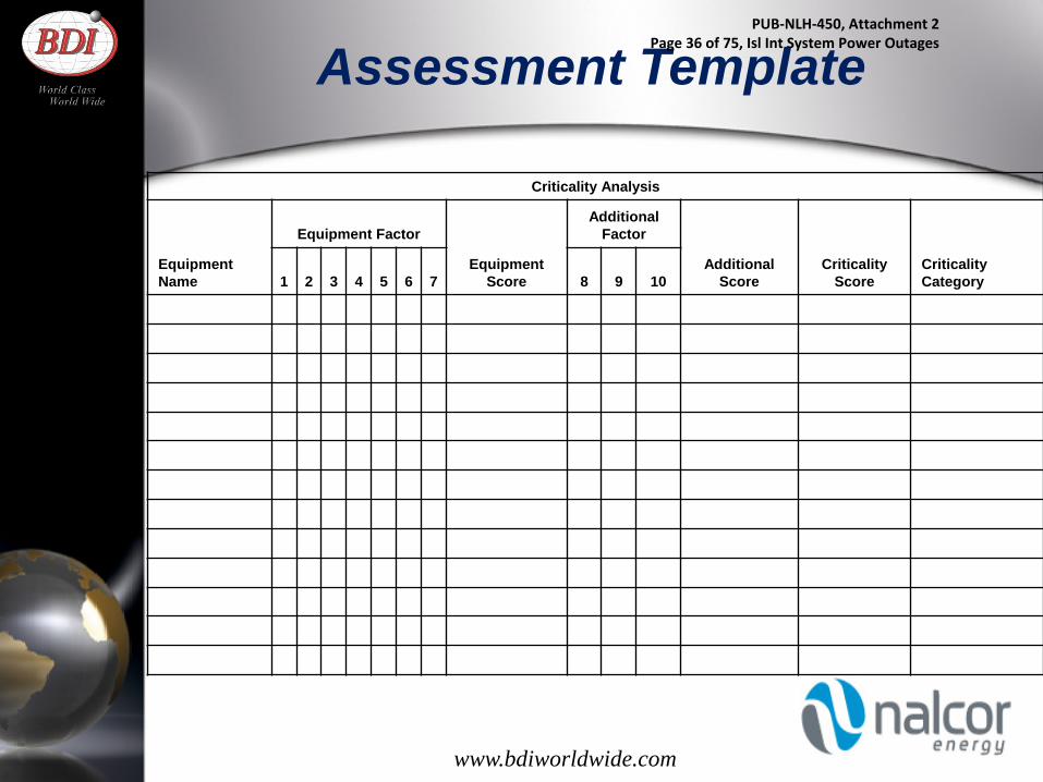
Criticality Analysis
Equipment Factor Additional
Factor
Equipment Name 1 2 3 4 5 6 7
Equipment Score 8 9 10
Additional Score
Criticality Score
Criticality Category
Assessment Template
www.bdiworldwide.com
PUB-NLH-450, Attachment 2 Page 36 of 75, Isl Int System Power Outages

Equipment Factors
FACTOR 1 - Health and SafetyLevel Definition Score
1 No effect 1
2 A non lost time accident or minor damage to plant is foreseeableless than 2 hours D/T
2
3 A lost time accident or serious damage to plant is foreseeable2 hours to 8 hours D/T
4
4 A serious injury or catastrophic damage to plantmore than 8 hours D/T
6
5 Loss of life or plant incident that is reportable to HSE (or Regional Equivalent)more than 8 hr D/T
10
Explanation:- Covers both maintenance and operation. Can cover both people and plant
FACTOR 2 - OutputLevel Definition Score
1 No effect 12 Reduced rate minor effect or one line off less than 10 mins 23 Reduced rate serious effect or one line off between 10 mins and 2 hours 34 One line off for 2-8 hours 45 Line off for more than 8 hours 8
Explanation:-
www.bdiworldwide.com
PUB-NLH-450, Attachment 2 Page 37 of 75, Isl Int System Power Outages
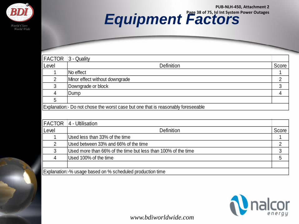
Equipment Factors
FACTOR 3 - QualityLevel Definition Score
1 No effect 12 Minor effect without downgrade 23 Downgrade or block 34 Dump 45
Explanation:- Do not chose the worst case but one that is reasonably foreseeable
FACTOR 4 - UltilisationLevel Definition Score
1 Used less than 33% of the time 12 Used between 33% and 66% of the time 23 Used more than 66% of the time but less than 100% of the time 34 Used 100% of the time 5
Explanation:-% usage based on % scheduled production time
www.bdiworldwide.com
PUB-NLH-450, Attachment 2 Page 38 of 75, Isl Int System Power Outages

Equipment Factors
FACTOR 5- AlternativesLevel Definition Score
1 Standby or alternative route readily available 12 Standby or alternative route available but with minor difficulty 23 Standby or alternative route available with difficulty 34 No standby or alternative route available without extreme difficulty 45 No alternative 6
Explanation:-
FACTOR 6 - EnvironmentLevel Definition Score
1 No effect 12 Minor local effect - can be contained on site eg noise/smell 2
3 More serious local / minor off-plant - liable to result in discharge to atmosphere or water course eg ammonia/fumes/oil
4
4 Reportable or exceeds consents - has potential for prosecution 65 More serious off-plant or off-site effect which involves outside services 10
Explanation: - Use reasonably foreseeable effects rather than worse case. Include dust, noise, gas, liquids etc. Use this factor where the effect on the environment is important. Include any effect caused while the equipment is breaking down, any knock on effect and any environmental effect due to the maintenance itself.
www.bdiworldwide.com
PUB-NLH-450, Attachment 2 Page 39 of 75, Isl Int System Power Outages
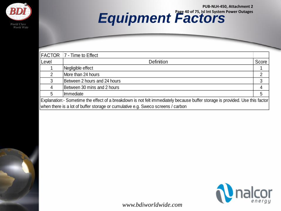
Equipment Factors
FACTOR 7 - Time to EffectLevel Definition Score
1 Negligible effect 12 More than 24 hours 23 Between 2 hours and 24 hours 34 Between 30 mins and 2 hours 45 Immediate 5
Explanation:- Sometime the effect of a breakdown is not felt immediately because buffer storage is provided. Use this factor when there is a lot of buffer storage or cumulative e.g. Sweco screens / carbon
www.bdiworldwide.com
PUB-NLH-450, Attachment 2 Page 40 of 75, Isl Int System Power Outages

Additional Factors
FACTOR 8- Mean Time Between Failures (MTBF)Level Definition Score
1 More than 1 yr MTBF 12 Between 3 mths and 1 year MTBF 23 Between 1 mth and 3 mths MTBF 34 Between 1 wk and 1 mth MTBF 45 Less than 1 wk MTBF 5
Explanation:- Use typical times not worst case
FACTOR 9 - Engineering Cost BreakdownLevel Definition Score
1 Less than $50 12 Between $50 and $250 23 Between $250 and $2500 34 Between $2500 and $5000 45 More than $5000 5
Explanation:- Includes labour materials and contractors, but not production costs. Includes cost of off-site repair. Use typical and not worst case figures
www.bdiworldwide.com
PUB-NLH-450, Attachment 2 Page 41 of 75, Isl Int System Power Outages

Additional Factors
FACTOR 10 - Effect of Waste or Energy LossLevel Definition Score
1 No energy loss 12 Minor energy loss 23 Moderate energy loss 34 Major energy loss 4
Explanation:- Better control, fewer interruptions, steadier optimum running will improve this.
www.bdiworldwide.com
PUB-NLH-450, Attachment 2 Page 42 of 75, Isl Int System Power Outages

Critical Spares Process
www.bdiworldwide.com
• Identify critical components for all critical equipment using criticality component template
• Identify critical components/parts for spares as appropriate and give to stores. Recommendation - Inventory critical components/parts only for emergencies that can’t be predicted or detected early or have a longer delivery lead time than the failure detection period.
• Identify critical components/parts for BOM’s as appropriate and give to planner for CMMS BOM
• Identify critical components and give to lube tech to breakdown into critical parts for their routes
• Identify critical components and give to CI to breakdown into critical parts for their routes
PUB-NLH-450, Attachment 2 Page 43 of 75, Isl Int System Power Outages

26
PUB-NLH-450, Attachment 2 Page 44 of 75, Isl Int System Power Outages

27
PUB-NLH-450, Attachment 2 Page 45 of 75, Isl Int System Power Outages

Critical Spares Process
www.bdiworldwide.com
When emergencies are reduced due to planned and scheduled maintenance, and equipment life is stable and lengthened, along with good Preventative and Predictive programs in place, ways to reduce inventory can be as follows: • Inventory depletion • Integrated Parts Supplier Inventory buyback – return to
vendor program • Integrated Parts Supplier Consigned Inventory program • Integrated Parts Supplier Critical Committed Inventory
program
PUB-NLH-450, Attachment 2 Page 46 of 75, Isl Int System Power Outages

Criticality Program Self-Assessment
Self-Assessment Score Sheet For Each
Category
Score = 76.6%
Lube Action Plan
STEP 2: Compares current lube practices against Best/World Class practices using standard worksheet
Visual Overview
Spider Diagram
Plant Maint’ce / CI Plan
STEP 1: Review critical elements within each category
STEP 3: Identify gaps & opportunities within each category
Lube Program Sustainability Audit
STEP 4: Develop lubrication action plan and slot into plant’s fiscal Maintenance/CI Plan
Complete Criticality List Critical Asset Description
Output Ranking
Health & Safety Ranking
Enviroment Ranking Critical Components
Stocked Spare Item
BOM Item
Ability to Detect (L/M/H)
Is it in Stock now? Y/N
Factor 8MTBF
BOILER Boiler E-stop Hand switch 8 10 1 E-stop switch X L N 1Influent Piping & Valves 8 1 4 10" blue brute pipe X L N 2COMPRESSOR 4 FRY PLANT 8 1 1 Motor X M N 1
Compressor X L NMain Boiler Clever Brooks 8 1 1 Forced air draft fan X M N 1HEAVY FUEL OIL SUPPLY Oil safety shutoff valve #1 Solen 8 1 1 Solenoid X L N 1
Valve X L NHEAVY FUEL OIL SUPPLY Oil safety shutoff valve #2 Solen 8 1 1 Solenoid X L N 1
Valve X L NHEAVY FUEL OIL SUPPLY Oil flow meter Flow transmitter 8 1 1 Transmitter X L Y 1
Controller X L NCOMBUSTION AIR Combustion air flow meter Flow transmi 8 1 1 Transmitter X L N 1PROPANE SUPPLY Propane safety shutoff valve #1 Soleno 8 1 1 solenoid X L Y 1
safety shutoff valve X L YPROPANE SUPPLY Propane vent valve Solenoid 8 1 1 solenoid X L N 1
Vent valve X L NPROPANE SUPPLY Propane safety shutoff valve #2 Soleno 8 1 1 solenoid X L N 1
safety shutoff valve X L NGAS MIXING CHAMBER Propane flame detector IR scanne 8 1 1 IR scanner X L Y 1STEAM DRUM Steam drum pressure Pressure transmitter 8 1 1 Transmitter X L N 1GAS MIXING CHAMBER Oil flame detector UV scanner 8 1 1 UV scanner X L Y 1HEAVY FUEL OIL SUPPLY Oil gun position verification Limi 8 1 1 Limit switch X L Y 1Heat Recovery Exhaust Fan M 108061 5 1 1 1FLU GAS Flue gas O2 Oxygen percent transmitter 4 1 6 Oxygen Transmitter X L N 1
Oxygen sensor X H NOil Miser Exhaust Fan M121046 4 1 1 1CONDENSER #5 REFRIGERATION 4 1 1 Drift eliminators X L N 1COMPRESSOR #5 FRY PLANT WATER PUMP 4 1 1 Pump X M N 1Should be condenser Motor X L NHEAVY FUEL OIL SUPPLY Oil flow control Control valve 4 1 1 Leslie Valve X L N 1
Positioner X L NCOMBUSTION AIR Combustion air damper Drive / positione 4 1 1 Air Damper X L N 1STORAGE TANK WATER LEVEL LEVEL TRANSMITTER 3 4 1 Ultrasonic level Transmitter X L Y 1Boiler Room Bunker Heat Set 3 1 2 Top Steam Heat exchanger X L N 1COMPRESSOR 1 FRY PLANT 3 1 1 Compressor X M N 1COMPRESSOR 2 FRY PLANT 3 1 1 Compressor X M N 1COMPRESSOR 3 FRY PLANT 3 1 1 Compressor X M N 1
Performance Score Chart
Best Practice 90-100%
Good 70-89%
Need Improvement <70% www.bdiworldwide.com
PUB-NLH-450, Attachment 2 Page 47 of 75, Isl Int System Power Outages

Closing Comments
Recognize that all assets are not created equal.
Remember that the model we are trying to implement is an “analysis” which, by definition, means to scrutinize or examine the data collected to gain knowledge for the purpose of making the best decisions.
www.bdiworldwide.com
PUB-NLH-450, Attachment 2 Page 48 of 75, Isl Int System Power Outages

FINAL REPORT, ASSET CRITICALITY ASSESSMENT AND CRITICAL SPARE PARTS ANALYSIS Appendix A BDI Documentation
September 26, 2014
ls c:\users\slamoureux\documents\bgk\nalcor\final report_bgk.docx A.2
A.2 BDI CRITICALITY DEFINITIONS
PUB-NLH-450, Attachment 2 Page 49 of 75, Isl Int System Power Outages

PUB-NLH-450, Attachment 2 Page 50 of 75, Isl Int System Power Outages

CRITICALITY DEFINITIONS
Page 1
FACTOR 1 - Health and Safety
Level Definition Score1 Minor 1
2 A medical treatment 2
3A lost time incident
4
4 A serious injury
6
5Loss of life
10
FACTOR 2 - Output (Capacity derating/ Outage Time to Repair)
Level Definition Score1 No effect 1
2 Reduced rate minor effect 2
3Reduced rate serious effect
3
4Off 2 hours to 8 hours
4
5 Off for more than 8 hours 8
FACTOR 3 - Quality Of Desired Output (Voltage/Frequency)
Level Definition Score1 No effect 12 Minor effect without downgrade 2
3 Downgrade or block 3
4 Dump (Underfrequency Load Shed) 4
FACTOR 4 - Utilization
Level Definition Score1 Used less than 33% of the time 1
2 Used between 33% and 66% of the time 2
Equipment Factors
Explanation:- Covers both maintenance and operation. Can cover both people and plant
Explanation:- Do not choose the worst case but one that is reasonably foreseeable
PUB-NLH-450, Attachment 2 Page 51 of 75, Isl Int System Power Outages
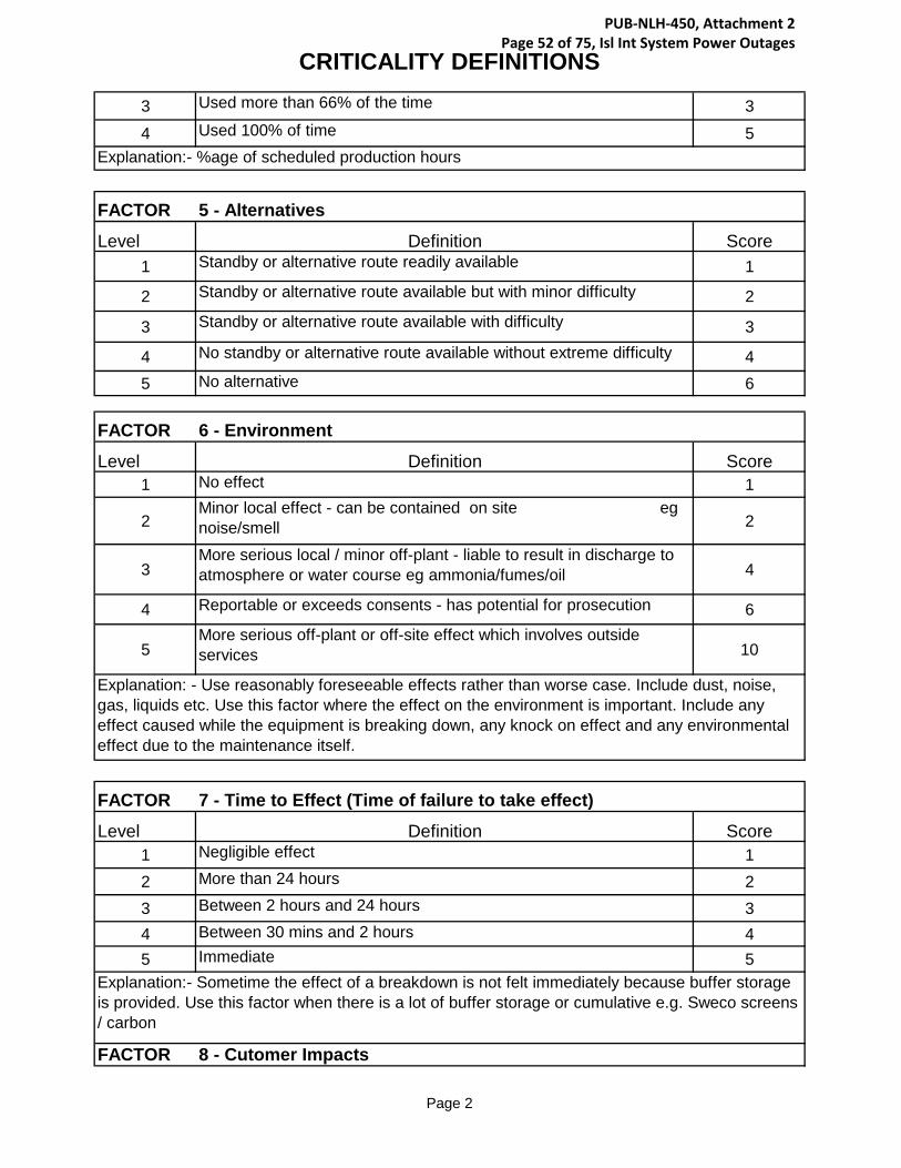
CRITICALITY DEFINITIONS
Page 2
3 Used more than 66% of the time 3
4 Used 100% of time 5
FACTOR 5 - Alternatives
Level Definition Score1 Standby or alternative route readily available 1
2 Standby or alternative route available but with minor difficulty 2
3 Standby or alternative route available with difficulty 3
4 No standby or alternative route available without extreme difficulty 45 No alternative 6
FACTOR 6 - Environment
Level Definition Score1 No effect 1
2Minor local effect - can be contained on site eg noise/smell 2
3More serious local / minor off-plant - liable to result in discharge to atmosphere or water course eg ammonia/fumes/oil 4
4 Reportable or exceeds consents - has potential for prosecution 6
5More serious off-plant or off-site effect which involves outside services 10
FACTOR 7 - Time to Effect (Time of failure to take effect)
Level Definition Score1 Negligible effect 12 More than 24 hours 23 Between 2 hours and 24 hours 34 Between 30 mins and 2 hours 45 Immediate 5
FACTOR 8 - Cutomer Impacts
Explanation: - Use reasonably foreseeable effects rather than worse case. Include dust, noise, gas, liquids etc. Use this factor where the effect on the environment is important. Include any effect caused while the equipment is breaking down, any knock on effect and any environmental effect due to the maintenance itself.
Explanation:- Sometime the effect of a breakdown is not felt immediately because buffer storage is provided. Use this factor when there is a lot of buffer storage or cumulative e.g. Sweco screens / carbon
Explanation:- %age of scheduled production hours
PUB-NLH-450, Attachment 2 Page 52 of 75, Isl Int System Power Outages
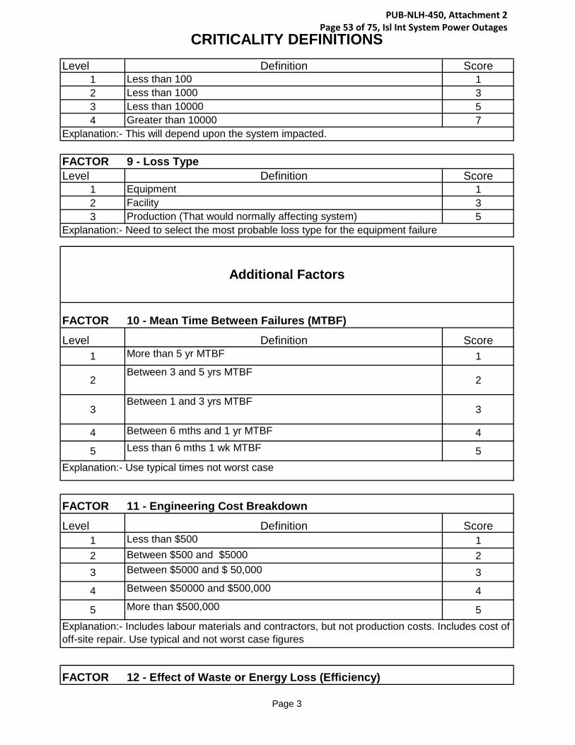
CRITICALITY DEFINITIONS
Page 3
Level Definition Score1 Less than 100 12 Less than 1000 33 Less than 10000 54 Greater than 10000 7
FACTOR 9 - Loss TypeLevel Definition Score
1 Equipment 12 Facility 33 Production (That would normally affecting system) 5
FACTOR 10 - Mean Time Between Failures (MTBF)
Level Definition Score1 More than 5 yr MTBF 1
2Between 3 and 5 yrs MTBF
2
3Between 1 and 3 yrs MTBF
3
4 Between 6 mths and 1 yr MTBF 4
5 Less than 6 mths 1 wk MTBF 5
FACTOR 11 - Engineering Cost Breakdown
Level Definition Score1 Less than $500 12 Between $500 and $5000 23 Between $5000 and $ 50,000 3
4 Between $50000 and $500,000 4
5 More than $500,000 5
FACTOR 12 - Effect of Waste or Energy Loss (Efficiency)
Explanation:- Includes labour materials and contractors, but not production costs. Includes cost of off-site repair. Use typical and not worst case figures
Explanation:- This will depend upon the system impacted.
Explanation:- Need to select the most probable loss type for the equipment failure
Additional Factors
Explanation:- Use typical times not worst case
PUB-NLH-450, Attachment 2 Page 53 of 75, Isl Int System Power Outages

CRITICALITY DEFINITIONS
Page 4
Level Definition Score1 No energy loss 12 Minor energy loss 23 Moderate energy loss 3
4 Major energy loss 4Explanation:- Better control, fewer interruptions, steadier optimum running will improve this.
PUB-NLH-450, Attachment 2 Page 54 of 75, Isl Int System Power Outages

FINAL REPORT, ASSET CRITICALITY ASSESSMENT AND CRITICAL SPARE PARTS ANALYSIS
Appendix B : Photographs, Hardwoods and Stephenville NL September 26, 2014
ls c:\users\slamoureux\documents\bgk\nalcor\final report_bgk.docx B.3
: PHOTOGRAPHS, HARDWOODS AND Appendix BSTEPHENVILLE NL
PUB-NLH-450, Attachment 2 Page 55 of 75, Isl Int System Power Outages

PUB-NLH-450, Attachment 2 Page 56 of 75, Isl Int System Power Outages
PUB-NLH-450, Attachment 2 Page 57 of 75, Isl Int System Power Outages

PUB-NLH-450, Attachment 2 Page 58 of 75, Isl Int System Power Outages

FINAL REPORT, ASSET CRITICALITY ASSESSMENT AND CRITICAL SPARE PARTS ANALYSIS Appendix C asset criticality assessment Spreadsheets
September 26, 2014
ls c:\users\slamoureux\documents\bgk\nalcor\final report_bgk.docx C.4
ASSET CRITICALITY ASSESSMENT SPREADSHEETS Appendix C
PUB-NLH-450, Attachment 2 Page 59 of 75, Isl Int System Power Outages

PUB-NLH-450, Attachment 2 Page 60 of 75, Isl Int System Power Outages

ASSET CRITICALITY ASSESSMENT - HARDWOODS FACILITY
Appendix C 133546352__HWD-001-B Criticality Analysis Revision 0.xls Page 1 of 7
Document No.: HWD-001-B
Revision Date By Approveda 8-Jul-14 - -b 18-Jul-14 BM -c 31-Jul-14 BM -d 8-Aug-14 BM -0 4-Sep-14 BM -
Inst
ance
s pe
r A
ssem
bly
Fact
or 1
Hea
lth &
Saf
ety
Fact
or 2
Out
put
Fact
or 3
Qua
lity
Fact
or 4
Util
izat
ion
Fact
or 5
A
ltern
ativ
es
Fact
or 6
Envi
ronm
ent
Fact
or 7
Tim
e to
Effe
ct
Fact
or 8
Cus
tom
er
Impa
cts
Fact
or 9
Loss
Typ
e
EquipmentScore Fa
ctor
10
MTB
F
Fact
or 1
1En
gine
erin
g C
ost
Bre
akdo
wn
Fact
or 1
2Ef
fect
of W
aste
or
Ene
rgy
Loss
AdditionalFactor Score
CriticalityScore
CriticalityCategory
A1 A2 A3 A4 A5 C1 C2
PRIME MOVER SYSTEMS, HWD GT 1END "A", PRIME MOVER SYSTEMS, HWD GT 1
Filter Box - Curtiss Wright (Dwg. 120-D-10562, Sheet 12/13), End "A", Prime Mover Systems, HWD GT 1 2 2 2 1 2 1 1 1 1 16 1 2 2 4 64Inertial Filter Element, Filter Box - Curtiss Wright, End "A", Prime Mover Systems, HWD GT 24 2 2 2 1 2 1 1 1 1 16 1 2 2 4 64High Efficiency Farr HP-100 Filter (2'x2'x2"), Filter Box - Curtiss Wright, End "A", Prime Mover Systems, HWD GT 1 2 2 1 2 1 1 1 1 8 3 2 2 12 96Blow-In Doors Limit Switch, Filter Box - Curtiss Wright, End "A", Prime Mover Systems, HWD GT 2 2 1 1 1 1 1 1 1 1 2 1 1 1 1 2Blow-In Doors Differential Pressure Switch, Filter Box - Curtiss Wright, End "A", Prime Mover Systems, HWD GT 1 2 1 1 1 1 1 1 1 1 2 1 1 1 1 2
Gas Generator Enclosure with Septum Doors (Dwg. 120-D-10562, Sheet 6/13), End "A", Prime Mover Systems, HWD GT 1 1 1 1 1 1 1 1 1 1 1 1 1 1 1 1Inlet Temperature Thermocouple, Gas Generator Enclosure with Septum Doors, End "A", Prime Mover Systems, HWD GT 1 1 1 1 1 1 1 1 1 1 1 1 1 1 1 1Inlet Pressure Transducer, Gas Generator Enclosure with Septum Doors, End "A", Prime Mover Systems, HWD GT 1 1 1 1 1 1 1 1 1 1 1 1 1 1 1 1Resistance Temperature Detector Probe, Gas Generator Enclosure with Septum Doors, End "A", Prime Mover Systems, HWD GT 1 1 1 1 1 1 1 1 1 1 1 1 1 1 1 1
Gas Generator (Docs. RR Olympus C Parts Catalogue, Hardwoods Operations & Maintenance Manual), End "A", Prime Mover Systems, HWD GT 1 6 8 3 1 2 2 5 1 5 14400 4 3 3 36 518400Liquid Fuel Burner - Complete (BDC.3026), Gas Generator, End "A", Prime Mover Systems, HWD GT 8 6 8 3 1 6 2 5 1 5 43200 4 3 3 36 1555200Combustion Chamber, Gas Generator, End "A", Prime Mover Systems, HWD GT 8 6 8 3 1 6 2 5 1 5 43200 4 3 3 36 1555200Anti-Icing Hot Air Valve - Complete (810-501-0747), Gas Generator, End "A", Prime Mover Systems, HWD GT 1 6 4 3 1 6 1 4 1 5 8640 5 3 3 45 388800Fuel Filter, Gas Generator, Prime Mover Systems, HWD GT 1 6 4 3 1 4 2 4 1 5 11520 4 2 2 16 184320Upper Fuel Pump Assembly, Gas Generator, End "A", Prime Mover Systems, HWD GT 1 6 8 3 1 6 2 5 1 5 43200 4 3 3 36 1555200Lower Fuel Pump Assembly, Gas Generator, End "A", Prime Mover Systems, HWD GT 1 6 8 3 1 6 2 5 1 5 43200 4 3 3 36 1555200Outer Fuel Pump Drive Assembly (BDA.7591), Gas Generator, End "A", Prime Mover Systems, HWD GT 1 6 8 3 1 6 2 5 1 5 43200 4 3 3 36 1555200Oil Filter Unit - Complete (B.108506), Gas Generator, End "A", Prime Mover Systems, HWD GT 1 6 4 3 1 4 2 4 1 5 11520 4 2 2 16 184320Oil Pump - Complete, Gas Generator, End "A", Prime Mover Systems, HWD GT 1 6 8 3 1 6 2 5 1 5 43200 4 3 3 36 1555200Outer Oil Pump Drive Assembly (47-1-1-006409), Gas Generator, End "A", Prime Mover Systems, HWD GT 1 6 8 3 1 6 2 5 1 5 43200 4 3 3 36 1555200Scavenge Pump Assembly (47-1-1-006418), Gas Generator, End "A", Prime Mover Systems, HWD GT 1 6 8 3 1 6 2 5 1 5 43200 4 3 3 36 1555200Outer Starter Drive Assembly (BDA.1153), Gas Generator, End "A", Prime Mover Systems, HWD GT 1 6 8 3 1 6 2 5 1 5 43200 4 3 3 36 1555200LP Compressor Magnetic Pickup, Gas Generator, End "A", Prime Mover Systems, HWD GT 6 4 3 1 6 1 5 1 5 10800 4 2 3 24 259200HP Compressor Magnetic Pickup, Gas Generator, End "A", Prime Mover Systems, HWD GT 6 4 3 1 6 1 5 1 5 10800 4 2 3 24 259200Vibration Transducer, Gas Generator, End "A", Prime Mover Systems, HWD GT 6 4 3 1 6 1 5 1 5 10800 4 2 3 24 259200High Energy Ignition Unit, Gas Generator, End "A", Prime Mover Systems, HWD GT 6 8 3 1 6 1 5 1 5 21600 4 3 3 36 777600
Power Turbine Model CT2 (Dwg. 494005N), End "A", Prime Mover Systems, HWD GT 1 6 8 3 1 2 2 5 1 5 14400 1 4 3 12 172800Thermocouple (181398N1), Power Turbine Model CT2, End "A", Prime Mover Systems, HWD GT 1 6 3 2 1 3 2 1 1 1 216 1 3 1 3 648Thermocouple (181398N2), Power Turbine Model CT2, End "A", Prime Mover Systems, HWD GT 1 4 3 2 1 3 2 1 1 1 144 1 3 1 3 432Thermocouple (184847), Power Turbine Model CT2, End "A", Prime Mover Systems, HWD GT 8 4 3 2 1 3 2 1 1 1 144 1 2 1 2 288Probe (181414N1), Power Turbine Model CT2, End "A", Prime Mover Systems, HWD GT 1 4 3 2 1 3 2 1 1 1 144 1 2 1 2 288Probe (181414N2), Power Turbine Model CT2, End "A", Prime Mover Systems, HWD GT 1 4 3 2 1 3 2 1 1 1 144 1 2 1 2 288Speed Pickup (181487), Power Turbine Model CT2, End "A", Prime Mover Systems, HWD GT 1 6 3 1 1 6 1 1 1 1 108 1 4 1 4 432Vibration Pickup (181571), Power Turbine Model CT2, End "A", Prime Mover Systems, HWD GT 1 6 3 1 1 6 1 1 1 1 108 1 4 1 4 432Bearing (181413 or 181332), Power Turbine Model CT2, End "A", Prime Mover Systems, HWD GT 1 6 8 3 1 6 2 5 1 3 25920 1 4 3 12 311040Bearing (494047), Power Turbine Model CT2, End "A", Prime Mover Systems, HWD GT 1 6 8 3 1 6 2 5 1 3 25920 1 4 3 12 311040Bearing (494056), Power Turbine Model CT2, End "A", Prime Mover Systems, HWD GT 1 6 8 3 1 6 2 5 1 3 25920 1 4 3 12 311040Thermocouple (181397), Power Turbine Model CT2, End "A", Prime Mover Systems, HWD GT 1 4 3 2 1 3 2 1 1 1 144 1 3 1 3 432Valve (181536), Power Turbine Model CT2, End "A", Prime Mover Systems, HWD GT 1 4 4 3 1 6 1 5 1 3 4320 1 2 3 6 25920Filter (494064), Power Turbine Model CT2, End "A", Prime Mover Systems, HWD GT 1 4 4 3 1 4 2 4 1 5 7680 4 2 2 16 122880
Exhaust, End "A", Prime Mover Systems, HWD GT 1 2 8 3 1 2 1 2 1 5 960 3 2 3 18 17280Snow Door Assembly, Exhaust, End "A", Prime Mover Systems, HWD GT 1 2 8 3 1 2 1 5 1 3 1440 1 2 3 6 8640
Pneumatic Cylinder, Snow Door Assembly, Exhaust, End "A", Prime Mover Systems, HWD GT 2 2 8 3 1 2 1 5 1 3 1440 1 2 3 6 8640Proximity Switch, Snow Door Assembly, Exhaust, End "A", Prime Mover Systems, HWD GT 2 2 8 3 1 2 1 5 1 3 1440 1 2 3 6 8640
Clutch (Dwg. SL13341), End "A", Prime Mover Systems, HWD GT 1 2 8 3 1 2 2 5 1 5 4800 5 2 3 30 144000Primary Ratchet Ring, Clutch, End "A", Prime Mover Systems, HWD GT 1 2 8 3 1 2 2 5 1 3 2880 1 3 3 9 25920Secondary Ratchet Ring, Clutch, End "A", Prime Mover Systems, HWD GT 1 2 8 3 1 2 2 5 1 3 2880 1 3 3 9 25920Primary Pawl, Clutch, End "A", Prime Mover Systems, HWD GT 4 2 8 3 1 2 2 5 1 3 2880 1 2 3 6 17280Secondary Pawl, Clutch, End "A", Prime Mover Systems, HWD GT 4 2 8 3 1 2 2 5 1 3 2880 1 2 3 6 17280Primary Pawl Spring, Clutch, End "A", Prime Mover Systems, HWD GT 4 2 8 3 1 2 2 5 1 3 2880 1 2 3 6 17280Proximity Switch, Clutch, End "A", Prime Mover Systems, HWD GT 1 2 8 3 1 2 2 5 1 3 2880 5 2 3 30 86400
END "B", PRIME MOVER SYSTEMS, HWD GT 1Filter Box - Curtiss Wright (Dwg. 120-D-10562, Sheet 12/13), End "B", Prime Mover Systems, HWD GT 1 2 2 2 1 2 1 1 1 1 16 1 2 2 4 64
Inertial Filter Element, Filter Box - Curtiss Wright, End "B", Prime Mover Systems, HWD GT 24 2 2 2 1 2 1 1 1 1 16 1 2 2 4 64High Efficiency Farr HP-100 Filter (2'x2'x2"), Filter Box - Curtiss Wright, End "B", Prime Mover Systems, HWD GT 1 2 2 1 2 1 1 1 1 8 3 2 2 12 96Blow-In Doors Limit Switch, Filter Box - Curtiss Wright, End "B", Prime Mover Systems, HWD GT 2 2 1 1 1 1 1 1 1 1 2 1 1 1 1 2Blow-In Doors Differential Pressure Switch, Filter Box - Curtiss Wright, End "B", Prime Mover Systems, HWD GT 1 2 1 1 1 1 1 1 1 1 2 1 1 1 1 2
Gas Generator Enclosure with Septum Doors (Dwg. 120-D-10562, Sheet 6/13), End "B", Prime Mover Systems, HWD GT 1 1 1 1 1 1 1 1 1 1 1 1 1 1 1 1Inlet Temperature Thermocouple, Gas Generator Enclosure with Septum Doors, End "B", Prime Mover Systems, HWD GT 1 1 1 1 1 1 1 1 1 1 1 1 1 1 1 1Inlet Pressure Transducer, Gas Generator Enclosure with Septum Doors, End "B", Prime Mover Systems, HWD GT 1 1 1 1 1 1 1 1 1 1 1 1 1 1 1 1Resistance Temperature Detector Probe, Gas Generator Enclosure with Septum Doors, End "B", Prime Mover Systems, HWD GT 1 1 1 1 1 1 1 1 1 1 1 1 1 1 1 1
Gas Generator (Docs. RR Olympus C Parts Catalogue, Hardwoods Operations & Maintenance Manual), End "B", Prime Mover Systems, HWD GT 1 6 8 3 1 2 2 5 1 5 14400 4 3 3 36 518400Liquid Fuel Burner - Complete (BDC.3026), Gas Generator, End "B", Prime Mover Systems, HWD GT 8 6 8 3 1 6 2 5 1 5 43200 4 3 3 36 1555200Combustion Chamber, Gas Generator, End "B", Prime Mover Systems, HWD GT 8 6 8 3 1 6 2 5 1 5 43200 4 3 3 36 1555200Anti-Icing Hot Air Valve - Complete (810-501-0747), Gas Generator, End "B", Prime Mover Systems, HWD GT 1 6 4 3 1 6 1 4 1 5 8640 5 3 3 45 388800Fuel Filter, Gas Generator, Prime Mover Systems, HWD GT 1 6 4 3 1 4 2 4 1 5 11520 4 2 2 16 184320Upper Fuel Pump Assembly, Gas Generator, End "B", Prime Mover Systems, HWD GT 1 6 8 3 1 6 2 5 1 5 43200 4 3 3 36 1555200Lower Fuel Pump Assembly, Gas Generator, End "B", Prime Mover Systems, HWD GT 1 6 8 3 1 6 2 5 1 5 43200 4 3 3 36 1555200
Equipment Name
DescriptionGroup Criticality Assessment - Grand Falls, NFIssued for ReviewIssued for ReviewPreliminary Milestone Issue - For ReviewIssued for Final Report
PUB-NLH-450, Attachment 2 Page 61 of 75, Isl Int System Power Outages

ASSET CRITICALITY ASSESSMENT - HARDWOODS FACILITY
Appendix C 133546352__HWD-001-B Criticality Analysis Revision 0.xls Page 2 of 7
Inst
ance
s pe
r A
ssem
bly
Fact
or 1
Hea
lth &
Saf
ety
Fact
or 2
Out
put
Fact
or 3
Qua
lity
Fact
or 4
Util
izat
ion
Fact
or 5
A
ltern
ativ
es
Fact
or 6
Envi
ronm
ent
Fact
or 7
Tim
e to
Effe
ct
Fact
or 8
Cus
tom
er
Impa
cts
Fact
or 9
Loss
Typ
e
EquipmentScore Fa
ctor
10
MTB
F
Fact
or 1
1En
gine
erin
g C
ost
Bre
akdo
wn
Fact
or 1
2Ef
fect
of W
aste
or
Ene
rgy
Loss
AdditionalFactor Score
CriticalityScore
CriticalityCategoryEquipment Name
Outer Fuel Pump Drive Assembly (BDA.7591), Gas Generator, End "B", Prime Mover Systems, HWD GT 1 6 8 3 1 6 2 5 1 5 43200 4 3 3 36 1555200Oil Filter Unit - Complete (B.108506), Gas Generator, End "B", Prime Mover Systems, HWD GT 1 6 4 3 1 4 2 4 1 5 11520 4 2 2 16 184320Oil Pump - Complete, Gas Generator, End "B", Prime Mover Systems, HWD GT 1 6 8 3 1 6 2 5 1 5 43200 4 3 3 36 1555200Outer Oil Pump Drive Assembly (47-1-1-006409), Gas Generator, End "B", Prime Mover Systems, HWD GT 1 6 8 3 1 6 2 5 1 5 43200 4 3 3 36 1555200Scavenge Pump Assembly (47-1-1-006418), Gas Generator, End "B", Prime Mover Systems, HWD GT 1 6 8 3 1 6 2 5 1 5 43200 4 3 3 36 1555200Outer Starter Drive Assembly (BDA.1153), Gas Generator, End "B", Prime Mover Systems, HWD GT 1 6 8 3 1 6 2 5 1 5 43200 4 3 3 36 1555200LP Compressor Magnetic Pickup, Gas Generator, End "B", Prime Mover Systems, HWD GT 6 4 3 1 6 1 5 1 5 10800 4 2 3 24 259200HP Compressor Magnetic Pickup, Gas Generator, End "B", Prime Mover Systems, HWD GT 6 4 3 1 6 1 5 1 5 10800 4 2 3 24 259200Vibration Transducer, Gas Generator, End "B", Prime Mover Systems, HWD GT 6 4 3 1 6 1 5 1 5 10800 4 2 3 24 259200High Energy Ignition Unit, Gas Generator, End "B", Prime Mover Systems, HWD GT 6 8 3 1 6 1 5 1 5 21600 4 3 3 36 777600
Power Turbine Model CT2 (Dwg. 494005N), End "B", Prime Mover Systems, HWD GT 1 6 8 3 1 2 2 5 1 5 14400 1 4 3 12 172800Thermocouple (181398N1), Power Turbine Model CT2, End "B", Prime Mover Systems, HWD GT 1 6 3 2 1 3 2 1 1 1 216 1 3 1 3 648Thermocouple (181398N2), Power Turbine Model CT2, End "B", Prime Mover Systems, HWD GT 1 4 3 2 1 3 2 1 1 1 144 1 3 1 3 432Thermocouple (184847), Power Turbine Model CT2, End "B", Prime Mover Systems, HWD GT 8 4 3 2 1 3 2 1 1 1 144 1 2 1 2 288Probe (181414N1), Power Turbine Model CT2, End "B", Prime Mover Systems, HWD GT 1 4 3 2 1 3 2 1 1 1 144 1 2 1 2 288Probe (181414N2), Power Turbine Model CT2, End "B", Prime Mover Systems, HWD GT 1 4 3 2 1 3 2 1 1 1 144 1 2 1 2 288Speed Pickup (181487), Power Turbine Model CT2, End "B", Prime Mover Systems, HWD GT 1 6 3 1 1 6 1 1 1 1 108 1 4 1 4 432Vibration Pickup (181571), Power Turbine Model CT2, End "B", Prime Mover Systems, HWD GT 1 6 3 1 1 6 1 1 1 1 108 1 4 1 4 432Bearing (181413 or 181332), Power Turbine Model CT2, End "B", Prime Mover Systems, HWD GT 1 6 8 3 1 6 2 5 1 3 25920 1 4 3 12 311040Bearing (494047), Power Turbine Model CT2, End "B", Prime Mover Systems, HWD GT 1 6 8 3 1 6 2 5 1 3 25920 1 4 3 12 311040Bearing (494056), Power Turbine Model CT2, End "B", Prime Mover Systems, HWD GT 1 6 8 3 1 6 2 5 1 3 25920 1 4 3 12 311040Thermocouple (181397), Power Turbine Model CT2, End "B", Prime Mover Systems, HWD GT 1 4 3 2 1 3 2 1 1 1 144 1 3 1 3 432Valve (181536), Power Turbine Model CT2, End "B", Prime Mover Systems, HWD GT 1 4 4 3 1 6 1 5 1 3 4320 1 2 3 6 25920Filter (494064), Power Turbine Model CT2, End "B", Prime Mover Systems, HWD GT 1 4 4 3 1 4 2 4 1 5 7680 4 2 2 16 122880
Exhaust, End "B", Prime Mover Systems, HWD GT 1 2 8 3 1 2 1 2 1 5 960 3 2 3 18 17280Snow Door Assembly, Exhaust, End "B", Prime Mover Systems, HWD GT 1 2 8 3 1 2 1 5 1 3 1440 1 2 3 6 8640
Pneumatic Cylinder, Snow Door Assembly, Exhaust, End "B", Prime Mover Systems, HWD GT 2 2 8 3 1 2 1 5 1 3 1440 1 2 3 6 8640Proximity Switch, Snow Door Assembly, Exhaust, End "B", Prime Mover Systems, HWD GT 2 2 8 3 1 2 1 5 1 3 1440 1 2 3 6 8640
Clutch (Dwg. SL13341), End "B", Prime Mover Systems, HWD GT 1 2 8 3 1 2 2 5 1 5 4800 5 2 3 30 144000Primary Ratchet Ring, Clutch, End "B", Prime Mover Systems, HWD GT 1 2 8 3 1 2 2 5 1 3 2880 1 3 3 9 25920Secondary Ratchet Ring, Clutch, End "B", Prime Mover Systems, HWD GT 1 2 8 3 1 2 2 5 1 3 2880 1 3 3 9 25920Primary Pawl, Clutch, End "B", Prime Mover Systems, HWD GT 4 2 8 3 1 2 2 5 1 3 2880 1 2 3 6 17280Secondary Pawl, Clutch, End "B", Prime Mover Systems, HWD GT 4 2 8 3 1 2 2 5 1 3 2880 1 2 3 6 17280Primary Pawl Spring, Clutch, End "B", Prime Mover Systems, HWD GT 4 2 8 3 1 2 2 5 1 3 2880 1 2 3 6 17280Proximity Switch, Clutch, End "B", Prime Mover Systems, HWD GT 1 2 8 3 1 2 2 5 1 3 2880 5 2 3 30 86400
POWER GENERATION SYSTEMS, HWD GT63 MVA 50 MW GENERATOR (Dwg. A03122987), POWER GENERATION SYSTEMS, HWD GT 1 1 8 3 1 6 2 5 3 5 21600 1 5 4 20 432000
Exciter Bearing, 63MVA 50MW Generator, Power Generation Systems, HWD GT 1 1 8 3 1 6 2 5 3 5 21600 1 4 4 16 345600Rotor Bearing, 63MVA 50MW Generator, Power Generation Systems, HWD GT 1 1 8 3 1 6 2 5 3 5 21600 1 4 4 16 345600Grounding Transformer, 63MVA 50MW Generator, Power Generation Systems, HWD GT 1 8 3 1 6 4 5 3 5 43200 1 3 4 12 518400Potential Transformers, 63MVA 50MW Generator, Power Generation Systems, HWD GT 1 8 3 1 6 4 5 3 5 43200 1 3 4 12 518400Current Transformers, 63MVA 50MW Generator, Power Generation Systems, HWD GT 1 8 3 1 6 4 5 3 5 43200 1 3 4 12 518400
STANDBY DIESEL GENERATOR, POWER GENERATION SYSTEMS, HWD GT 1 2 1 1 1 2 2 1 1 1 8 1 3 1 3 24Stand By Diesel Unit 572, Standby Diesel Generator, Power Generation Systems, HWD GT 1 2 1 1 1 2 2 1 1 1 8 1 3 1 3 2424 VDC Battery Charger, Standby Diesel Generator, Power Generation Systems, HWD GT 1 1 1 1 1 2 1 1 1 1 2 1 2 1 2 4
A.C. ELECTRICAL SYSTEM, POWER GENERATION SYSTEMS, HWD GT 1 4 3 3 1 2 1 5 1 5 1800 1 3 3 9 16200Station Service Transformer, A.C. Electrical System, Power Generation Systems, HWD GTUnit Transformer, A.C. Electrical System, Power Generation Systems, HWD GTGenerator Transformer, A.C. Electrical System, Power Generation Systems, HWD GTDisconnect Breakers (Station Service/Generator), A.C. Electrical System, Power Generation Systems, HWD GTUnit Control (DCS), A.C. Electrical System, Power Generation Systems, HWD GTMain Breaker G1T5, A.C. Electrical System, Power Generation Systems, HWD GTUnit Relaying, A.C. Electrical System, Power Generation Systems, HWD GTVibration Protection, A.C. Electrical System, Power Generation Systems, HWD GTPotential Transformers, A.C. Electrical System, Power Generation Systems, HWD GTCurrent Transformers, A.C. Electrical System, Power Generation Systems, HWD GTBus, A.C. Electrical System, Power Generation Systems, HWD GT
D.C. ELECTRICAL SYSTEM, POWER GENERATION SYSTEMS, HWD GT125 VDC Battery Charger, D.C. Electrical System, Power Generation Systems, HWD GT 1 1 1 1 1 2 1 1 1 1 2 1 2 1 2 4
125 VDC Battery Bank, D.C. Electrical System, Power Generation Systems, HWD GT 1 2 8 3 1 2 2 3 1 1 576 1 3 1 3 1728Battery, 125 VDC Battery Bank, D.C. Electrical System, Power Generation Systems, HWD GT 1 2 8 3 1 2 2 3 1 1 576 1 3 1 3 1728
AUXILIARY SYSTEMS, HWD GTLIQUID FUEL SYSTEM (Dwg. 183511), AUXILIARY SYSTEMS, HWD GT 1 2 1 1 1 1 4 1 1 1 8 1 3 1 3 24
AC Pump (P&M-LF-4), Liquid Fuel System, Auxiliary Systems, HWD GT 1 2 1 1 1 1 2 1 1 1 4 1 3 1 3 12AC Pump (P&M-LF-5), Liquid Fuel System, Auxiliary Systems, HWD GT 1 2 1 1 1 1 2 1 1 1 4 1 3 1 3 12Offloading Filter (F-LF-4), Liquid Fuel System, Auxiliary Systems, HWD GT 1 2 1 1 1 1 2 1 1 1 4 3 2 1 6 24Offloading Flow Meter (FM-LF-2), Liquid Fuel System, Auxiliary Systems, HWD GT 1 2 1 1 1 1 2 1 1 1 4 1 3 1 3 12Motor Operated Tank Shutoff Valve (LF-38), Liquid Fuel System, Auxiliary Systems, HWD GT 1 2 2 1 1 1 4 5 1 1 80 1 3 1 3 240Fuel Supply Flow Meter (FM-LF-1), Liquid Fuel System, Auxiliary Systems, HWD GT 1 2 2 1 1 1 2 5 1 1 40 1 3 1 3 120DC Pump (P&M-LF-1), Liquid Fuel System, Auxiliary Systems, HWD GT 1 2 4 3 1 1 2 5 3 5 3600 1 3 4 12 43200AC Pump (P&M-LF-2), Liquid Fuel System, Auxiliary Systems, HWD GT 1 2 1 1 1 1 2 1 1 1 4 1 3 1 3 12AC Pump (P&M-LF-3), Liquid Fuel System, Auxiliary Systems, HWD GT 1 2 1 1 1 1 2 1 1 1 4 1 3 1 3 12AC Pump Discharge Fuel Pressure Switch (PS-LF-1), Liquid Fuel System, Auxiliary Systems, HWD GT 1 1 1 1 1 1 2 1 1 1 2 1 2 1 2 4AC Pump Discharge Fuel Pressure Switch (PS-LF-4), Liquid Fuel System, Auxiliary Systems, HWD GT 1 1 1 1 1 1 2 1 1 1 2 1 2 1 2 4Heater Outlet Relief Valve (LF-15), Liquid Fuel System, Auxiliary Systems, HWD GT 1 3 1 1 1 2 2 1 1 1 12 1 2 1 2 24Heater (HTR-LF-3), Liquid Fuel System, Auxiliary Systems, HWD GT 1 2 2 1 1 2 1 1 1 1 8 1 2 1 2 16Pre-filter (F-LF-3), Liquid Fuel System, Auxiliary Systems, HWD GT 1 2 2 1 1 3 2 2 1 1 48 2 2 1 4 192Pre-filter Relief Valve (LF-24), Liquid Fuel System, Auxiliary Systems, HWD GT 1 3 1 1 1 2 2 1 1 1 12 1 2 1 2 24Pre-filter Differential Pressure Switch (PSD-LF-2), Liquid Fuel System, Auxiliary Systems, HWD GT 1 1 2 1 1 1 2 1 1 1 4 1 2 1 2 8Filter/Coalescer (F-LF-2), Liquid Fuel System, Auxiliary Systems, HWD GT 1 2 2 1 1 3 2 2 1 1 48 2 2 1 4 192Filter/Coalescer Heater (HTR-LF-1), Liquid Fuel System, Auxiliary Systems, HWD GT 1 2 2 1 1 2 1 1 1 1 8 1 2 1 2 16Filter/Coalescer Relief Valve (LF-24), Liquid Fuel System, Auxiliary Systems, HWD GT 1 3 1 1 1 2 2 1 1 1 12 1 2 1 2 24
PUB-NLH-450, Attachment 2 Page 62 of 75, Isl Int System Power Outages

ASSET CRITICALITY ASSESSMENT - HARDWOODS FACILITY
Appendix C 133546352__HWD-001-B Criticality Analysis Revision 0.xls Page 3 of 7
Inst
ance
s pe
r A
ssem
bly
Fact
or 1
Hea
lth &
Saf
ety
Fact
or 2
Out
put
Fact
or 3
Qua
lity
Fact
or 4
Util
izat
ion
Fact
or 5
A
ltern
ativ
es
Fact
or 6
Envi
ronm
ent
Fact
or 7
Tim
e to
Effe
ct
Fact
or 8
Cus
tom
er
Impa
cts
Fact
or 9
Loss
Typ
e
EquipmentScore Fa
ctor
10
MTB
F
Fact
or 1
1En
gine
erin
g C
ost
Bre
akdo
wn
Fact
or 1
2Ef
fect
of W
aste
or
Ene
rgy
Loss
AdditionalFactor Score
CriticalityScore
CriticalityCategoryEquipment Name
Filter/Coalescer Automatic Drain Valve (LF-12), Liquid Fuel System, Auxiliary Systems, HWD GT 1 2 1 1 1 1 2 1 1 1 4 1 2 1 2 8Filter/Coalescer Automatic Air Vent Valve (LF-11), Liquid Fuel System, Auxiliary Systems, HWD GT 1 3 1 1 1 3 1 1 1 1 9 1 2 1 2 18Fire Fuel Shutoff Valve (LF-8), Liquid Fuel System, Auxiliary Systems, HWD GT 2 5 4 3 1 6 6 5 3 3 97200 1 2 2 4 388800Fuel Temperature Sensor (TS-LF-1), Liquid Fuel System, Auxiliary Systems, HWD GT 2 1 1 1 1 1 1 1 1 1 1 1 2 1 2 2Final Fuel Filter (F-LF-1), Liquid Fuel System, Auxiliary Systems, HWD GT 2 2 2 1 1 3 2 2 1 1 48 2 2 1 4 192Final Fuel Filter Differential Pressure Switch (PSD-LF-A), Liquid Fuel System, Auxiliary Systems, HWD GT 2 1 2 1 1 1 2 1 1 1 4 1 2 1 2 8Fuel Regulator (LF-4), Liquid Fuel System, Auxiliary Systems, HWD GT 2 2 4 3 1 6 2 5 3 3 12960 1 2 2 4 51840Supplemental Fuel AC Pump (P&MLF-5), Liquid Fuel System, Auxiliary Systems, HWD GT 2 2 4 3 1 6 2 5 3 3 12960 1 3 2 6 77760Supplemental Fuel Relief Valve (LF-35), Liquid Fuel System, Auxiliary Systems, HWD GT 2 3 1 1 1 2 2 1 1 1 12 1 2 1 2 24Supplemental Fuel Filter (F-LF-5), Liquid Fuel System, Auxiliary Systems, HWD GT 2 2 2 1 1 3 2 5 3 3 1080 2 2 2 8 8640Fuel Inlet Relief Valve (LF-5), Liquid Fuel System, Auxiliary Systems, HWD GT 2 3 1 1 1 2 2 1 1 1 12 1 2 1 2 24Fuel Recirculation Solenoid Valve (LF-7), Liquid Fuel System, Auxiliary Systems, HWD GT 2 2 4 3 1 6 2 5 3 3 12960 1 2 2 4 51840Fuel Pump Servo Valve (SV-LF-1), Liquid Fuel System, Auxiliary Systems, HWD GT 2 2 4 3 1 6 2 5 3 3 12960 1 2 2 4 51840Fuel Pressure Transducer (PT-LF-1), Liquid Fuel System, Auxiliary Systems, HWD GT 2 1 1 1 1 1 2 1 1 1 2 1 2 1 2 4Pressure Switch, Permissive Start - Low Pressure Alarm (PS-LF-2), Liquid Fuel System, Auxiliary Systems, HWD GT 2 1 4 3 1 3 2 5 3 3 3240 1 2 2 4 12960Pressure Switch, Trip - Low Fuel Pressure (PS-LF-3), Liquid Fuel System, Auxiliary Systems, HWD GT 2 1 4 3 1 3 2 5 3 3 3240 1 2 2 4 12960P3 Pressure Transducer (PT-P3-1), Liquid Fuel System, Auxiliary Systems, HWD GT 2 1 1 1 1 1 2 1 1 1 2 1 2 1 2 4Altair Quick Shutoff Valve (AV-LF-1), Liquid Fuel System, Auxiliary Systems, HWD GT 2 2 4 3 1 6 2 5 3 3 12960 1 3 2 6 77760Fuel Valve (FC-LF-1), Liquid Fuel System, Auxiliary Systems, HWD GT 2 2 4 3 1 6 2 5 3 3 12960 1 3 2 6 77760Actuator - Hydraulic & DC Motor (A-LF-1), Liquid Fuel System, Auxiliary Systems, HWD GT 2 2 4 3 1 6 2 5 3 3 12960 1 3 2 6 77760Pressure Switch (PS-HO-1), Liquid Fuel System, Auxiliary Systems, HWD GT 2 1 1 1 1 1 2 1 1 1 2 1 2 1 2 4Hydraulic Actuator Supply Filter (F-HO-1), Liquid Fuel System, Auxiliary Systems, HWD GT 2 2 2 1 1 1 2 1 1 1 8 1 2 1 2 16Fuel Supply Thermocouple (TC-LF-1), Liquid Fuel System, Auxiliary Systems, STV GT 2 1 2 1 1 1 1 1 1 1 2 1 2 1 2 4
MAIN LUBE OIL SYSTEM (Dwg. 183482), AUXILIARY SYSTEMS, HWD GT 1 2 1 1 1 1 2 1 1 1 4 1 4 1 4 16Main AC Pump (P-LO-1), Main Lube Oil System, Auxiliary Systems, HWD GT 1 2 1 1 1 1 2 1 1 1 4 1 3 1 3 12Auxiliary AC Pump (P-LO-2), Main Lube Oil System, Auxiliary Systems, HWD GT 1 2 1 1 1 1 2 1 1 1 4 1 3 1 3 12Emergency DC Pump (P-LO-3), Main Lube Oil System, Auxiliary Systems, HWD GT 1 2 1 1 1 1 2 1 1 1 4 1 3 1 3 12Emergency DC Pump (P-LO-4), Main Lube Oil System, Auxiliary Systems, HWD GT 1 2 1 1 1 1 2 1 1 1 4 1 3 1 3 12DC Pump Start Pressure Switch (PS-LO-3), Main Lube Oil System, Auxiliary Systems, HWD GT 1 1 1 1 1 1 2 1 1 1 2 1 2 1 2 4Pump Header Relief Valve (LO-2), Main Lube Oil System, Auxiliary Systems, HWD GT 1 3 1 1 1 6 2 1 1 1 36 1 2 1 2 72Pressure Regulating Valve (LO-8), Main Lube Oil System, Auxiliary Systems, HWD GT 1 2 1 1 1 3 2 3 1 1 36 1 2 1 2 72Filter Input 3-Way Valve (LO-10), Main Lube Oil System, Auxiliary Systems, HWD GT 1 2 2 1 1 2 2 1 1 1 16 1 2 1 2 32Duplex 25u Filter (F-LO-1), Main Lube Oil System, Auxiliary Systems, HWD GT 2 2 1 1 1 1 2 1 1 1 4 2 2 1 4 16Filter Differential Pressure Switch (PSD-LO-1), Main Lube Oil System, Auxiliary Systems, HWD GT 1 1 2 1 1 2 2 1 1 1 8 1 2 1 2 16Start Permissive Pressure Switch (PS-LO-6), Main Lube Oil System, Auxiliary Systems, HWD GT 1 1 4 3 1 3 2 5 3 5 5400 1 2 4 8 43200Low Trip Pressure Switch (PS-LO-7), Main Lube Oil System, Auxiliary Systems, HWD GT 1 1 4 3 1 3 2 5 3 5 5400 1 2 4 8 43200Oil Supply Thermocouple (TC-LO-1), Main Lube Oil System, Auxiliary Systems, HWD GT 1 1 1 1 1 1 1 1 1 1 1 1 2 1 2 2Oil Heater (HTR-LO-1), Main Lube Oil System, Auxiliary Systems, HWD GT 2 2 1 1 1 1 1 1 1 1 2 1 2 1 2 4Heater Control Temperature Switch (TS-LO-1), Main Lube Oil System, Auxiliary Systems, HWD GT 1 1 2 1 1 3 1 1 1 1 6 1 2 1 2 12AC Evacuator Fan (EV-AC), Main Lube Oil System, Auxiliary Systems, HWD GT 1 2 1 1 1 3 1 1 1 1 6 1 2 1 2 12AC Oil Separator (OS-AC), Main Lube Oil System, Auxiliary Systems, HWD GT 1 2 1 1 1 1 4 2 1 1 16 1 2 1 2 32Tank Level Switch (LS-LO-1), Main Lube Oil System, Auxiliary Systems, HWD GT 1 2 1 1 1 6 2 1 1 1 24 1 2 1 2 48Clutch Control Solenoid Valve (LO-6), Main Lube Oil System, Auxiliary Systems, HWD GT 2 2 3 3 1 6 2 5 2 3 6480 1 3 2 6 38880Oil Drain Thermocouple (TC-LO-2), Main Lube Oil System, Auxiliary Systems, HWD GT 2 1 1 1 1 1 1 1 1 1 1 1 2 1 2 2Jacking Oil Pump (PJO-1), Main Lube Oil System, Auxiliary Systems, HWD GT 1 2 4 3 1 6 2 5 3 5 21600 1 3 4 12 259200Jacking Oil Pump (PJO-2), Main Lube Oil System, Auxiliary Systems, HWD GT 1 2 4 3 1 6 2 5 3 5 21600 1 3 4 12 259200Jacking Oil Permissive Pressure Switch (PS-LO-5), Main Lube Oil System, Auxiliary Systems, HWD GT 2 1 4 3 1 3 2 5 3 5 5400 1 2 4 8 43200Jacking Oil Relief Valve (LO-21), Main Lube Oil System, Auxiliary Systems, HWD GT 2 3 1 1 1 6 2 1 1 1 36 1 2 1 2 72Alternator Bearing Drain Oil Thermocouple (TC-LO-3), Main Lube Oil System, Auxiliary Systems, HWD GT 3 1 1 1 1 1 1 1 1 1 1 1 2 1 2 2
GAS GENERATOR LUBE OIL SYSTEM (Dwg. 183480), AUXILIARY SYSTEMS, HWD GT 2 2 8 3 1 2 2 5 1 5 4800 1 3 3 9 43200Heater (HTR-GGLO-1), Gas Generator Lube Oil System, Auxiliary Systems, HWD GT 1 2 2 1 1 2 1 1 1 1 8 1 2 1 2 16Oil Supply Thermocouple (TC-GGLO-1), Gas Generator Lube Oil System, Auxiliary Systems, HWD GT 1 1 1 1 1 1 1 1 1 1 1 1 2 1 2 2Level Switch (LS-GGLO-1), Gas Generator Lube Oil System, Auxiliary Systems, HWD GT 1 2 1 1 1 3 2 1 1 1 12 1 2 1 2 24Relief Valve (GGLO-2), Gas Generator Lube Oil System, Auxiliary Systems, HWD GT 1 3 1 1 1 6 2 1 1 1 36 1 2 1 2 72Heater Control Temperature Switch (TS-GGLO-1), Gas Generator Lube Oil System, Auxiliary Systems, HWD GT 1 1 2 1 1 3 1 1 1 1 6 1 2 1 2 12Low Oil Pressure Switch (PS-GGLO-1), Gas Generator Lube Oil System, Auxiliary Systems, HWD GT 1 1 3 1 1 2 2 5 1 1 60 1 2 1 2 120Low Oil Pressure Switch (PS-GGLO-2), Gas Generator Lube Oil System, Auxiliary Systems, HWD GT 1 1 1 1 1 1 2 1 1 1 2 1 2 1 2 4Filter Upstream Pressure Switch (PS-GGLO-3), Gas Generator Lube Oil System, Auxiliary Systems, HWD GT 1 1 2 1 1 2 2 1 1 1 8 1 2 1 2 16Filter (F-GGLO-1), Gas Generator Lube Oil System, Auxiliary Systems, HWD GT 1 2 1 1 1 2 2 1 1 1 8 2 2 1 4 32
MAIN LUBE OIL / GLYCOL COOLING SYSTEM (Dwg. 183517), AUXILIARY SYSTEMS, HWD GT 1 0 0 0Glycol to Air Heat Exchanger (HE-GA-1), MLO/Glycol Cooling System, Auxiliary Systems, HWD GT 1 2 1 1 1 1 4 1 1 1 8 1 2 1 2 163-Way Thermostatic Valve (GL-2), MLO/Glycol Cooling System, Auxiliary Systems, HWD GT 1 2 3 1 1 6 4 3 1 1 432 1 2 1 2 864AC Cooling Pump (P-GL-1), MLO/Glycol Cooling System, Auxiliary Systems, HWD GT 1 2 3 1 1 6 4 3 1 1 432 1 2 1 2 864Low Liquid Level Alarm Switch (LL-GL-1), MLO/Glycol Cooling System, Auxiliary Systems, HWD GT 1 2 1 1 1 6 4 1 1 1 48 1 2 1 2 96Oil to Glycol Heat Exchanger (CLR-LO-1), MLO/Glycol Cooling System, Auxiliary Systems, HWD GT 1 2 4 3 1 6 4 3 3 5 25920 1 3 3 9 233280
GAS GENERATOR AIR STARTER SYSTEM (Dwg. 183481), AUXILIARY SYSTEMS, HWD GT 1 2 2 2 1 1 1 1 1 1 8 2 2 1 4 32AC Air Compressor (C-CA-1), Gas Generator Air Starter System, Auxiliary Systems, HWD GT 1 2 2 2 1 1 1 1 1 1 8 2 2 1 4 32AC Air Compressor (C-CA-2), Gas Generator Air Starter System, Auxiliary Systems, HWD GT 1 2 2 2 1 1 1 1 1 1 8 2 2 1 4 32Compressor Start-Stop Pressure Switch (PS-CA-1), Gas Generator Air Starter System, Auxiliary Systems, HWD GT 1 1 2 1 1 1 1 1 1 1 2 1 1 1 1 2Compressor Start-Stop Pressure Switch (PS-CA-2), Gas Generator Air Starter System, Auxiliary Systems, HWD GT 1 1 2 1 1 1 1 1 1 1 2 1 1 1 1 2Snubber (SN-CA-1), Gas Generator Air Starter System, Auxiliary Systems, HWD GT 2 1 2 1 1 1 1 1 1 1 2 1 1 1 1 2Air Compressor Relief Valve (CA-14), Gas Generator Air Starter System, Auxiliary Systems, HWD GT 2 3 1 1 1 1 1 1 1 1 3 1 2 1 2 6Air Receiver Relief Valve (CA-13), Gas Generator Air Starter System, Auxiliary Systems, HWD GT 2 3 1 1 1 1 1 1 1 1 3 1 2 1 2 6Heating Cable (HTR-CA-1), Gas Generator Air Starter System, Auxiliary Systems, HWD GT 2 2 2 1 1 2 2 1 1 1 16 1 1 1 1 16Automatic Condensate Drain Trap (DT-CA-1), Gas Generator Air Starter System, Auxiliary Systems, HWD GT 2 1 2 1 1 2 1 1 1 1 4 1 1 1 1 4Gas Generator Permissive Start Pressure Switch (PS-CA-4), Gas Generator Air Starter System, Auxiliary Systems, HWD GT 2 1 3 3 1 3 1 5 1 3 405 1 2 2 4 1620Starter Control Valve (CA-17), Gas Generator Air Starter System, Auxiliary Systems, HWD GT 2 1 3 3 1 6 1 5 1 3 810 1 2 2 4 3240Starter Overpressure Pressure Switch (PS-CA-3), Gas Generator Air Starter System, Auxiliary Systems, HWD GT 2 1 3 3 1 3 1 5 1 3 405 1 2 2 4 1620Relief Valve (CA-20), Gas Generator Air Starter System, Auxiliary Systems, HWD GT 2 3 1 1 1 6 1 1 1 1 18 1 2 1 2 36Control Air Dryer (F-CA-1), Gas Generator Air Starter System, Auxiliary Systems, HWD GT 2 1 1 1 1 1 1 1 1 1 1 1 2 1 2 2NO Solenoid Valve (SV-CA-1), Gas Generator Air Starter System, Auxiliary Systems, HWD GT 2 1 3 3 1 6 1 5 1 3 810 1 2 2 4 3240NC Solenoid Valve (SV-CA-2), Gas Generator Air Starter System, Auxiliary Systems, HWD GT 2 1 3 3 1 6 1 5 1 3 810 1 2 2 4 3240NC Solenoid Valve (SV-CA-3), Gas Generator Air Starter System, Auxiliary Systems, HWD GT 2 1 1 1 1 2 1 1 1 1 2 1 2 1 2 4
PUB-NLH-450, Attachment 2 Page 63 of 75, Isl Int System Power Outages

ASSET CRITICALITY ASSESSMENT - HARDWOODS FACILITY
Appendix C 133546352__HWD-001-B Criticality Analysis Revision 0.xls Page 4 of 7
Inst
ance
s pe
r A
ssem
bly
Fact
or 1
Hea
lth &
Saf
ety
Fact
or 2
Out
put
Fact
or 3
Qua
lity
Fact
or 4
Util
izat
ion
Fact
or 5
A
ltern
ativ
es
Fact
or 6
Envi
ronm
ent
Fact
or 7
Tim
e to
Effe
ct
Fact
or 8
Cus
tom
er
Impa
cts
Fact
or 9
Loss
Typ
e
EquipmentScore Fa
ctor
10
MTB
F
Fact
or 1
1En
gine
erin
g C
ost
Bre
akdo
wn
Fact
or 1
2Ef
fect
of W
aste
or
Ene
rgy
Loss
AdditionalFactor Score
CriticalityScore
CriticalityCategoryEquipment Name
Air Regulator (CA-17-A), Gas Generator Air Starter System, Auxiliary Systems, HWD GT 2 1 1 1 1 2 1 1 1 1 2 1 2 1 2 4Air Regulator (CA-17-B), Gas Generator Air Starter System, Auxiliary Systems, HWD GT 2 1 1 1 1 2 1 1 1 1 2 1 2 1 2 4
FIRE PROTECTION SYSTEM, AUXILIARY SYSTEMS, HWD GT 1 1 1 1 2 1 1 1 1 2 1 2 1 2 4Control Room Inergen System, Fire Protection System, Auxiliary Systems, HWD GT 0 0 0
Compressed Gas Tank, Control Room Inergen System, Fire Protection System, Auxiliary Systems, HWD GT 0 0 0Power Generation Module Inergen System, Fire Protection System, Auxiliary Systems, HWD GT 0 0 0
Compressed Gas Tank, Power Generation Module Inergen System, Fire Protection System, Auxiliary Systems, HWD GT 0 0 0Switchgear Room Inergen System, Fire Protection System, Auxiliary Systems, HWD GT 0 0 0
Compressed Gas Tank, Switchgear Module Inergen System, Fire Protection System, Auxiliary Systems, HWD GT 0 0 00 0 0
BUILDINGS AND PROPERTY, HWD GT 0 0 0Maintenance Building, HWD GT 0 0 0Control Module, HWD GT 0 0 0Switchgear Module, HWD GT 0 0 0Fuel Forwarding Module, HWD GT 0 0 0Diesel Building, HWD GT 0 0 0Fence, HWD GT 0 0 0Water System, HWD GT 0 0 0Waste Disposal System, HWD GT 0 0 0Fall Protection System, HWD GT 0 0 0End A Overhead Crane, HWD GT 0 0 0End B Overhead Crane, HWD GT 0 0 0Sump and Drain Lines, HWD GT 0 0 0Portable Washrooms, HWD GT 0 0 0
PUB-NLH-450, Attachment 2 Page 64 of 75, Isl Int System Power Outages

ASSET CRITICALITY ASSESSMENT - HARDWOODS FACILITYCritical Components
Appendix C 133546352__HWD-001-B Criticality Analysis Revision 0.xls
Asset Number Asset DescriptionOutput
Ranking
Health & Safety
Ranking
Enviroment
Ranking
Stocked Spare Item
BOM Item
Ability to
Detect (L/M/H)
Factor 8MTBF
CI Item
Lube Item
Std Job Item
PdM Itemlater
PM Itemlater
88101 JET ENGINE A 1555200 6 2 Liquid Fuel Burner - Complete (BDC.3026), Gas Generator, End "A", Prime Mover Systems, HWD GT 488101 JET ENGINE A 1555200 6 2 Combustion Chamber, Gas Generator, End "A", Prime Mover Systems, HWD GT 488101 JET ENGINE A 1555200 6 2 Upper Fuel Pump Assembly, Gas Generator, End "A", Prime Mover Systems, HWD GT 488101 JET ENGINE A 1555200 6 2 Lower Fuel Pump Assembly, Gas Generator, End "A", Prime Mover Systems, HWD GT 488101 JET ENGINE A 1555200 6 2 Outer Fuel Pump Drive Assembly (BDA.7591), Gas Generator, End "A", Prime Mover Systems, HWD GT 488101 JET ENGINE A 1555200 6 2 Oil Pump - Complete, Gas Generator, End "A", Prime Mover Systems, HWD GT 488101 JET ENGINE A 1555200 6 2 Outer Oil Pump Drive Assembly (47-1-1-006409), Gas Generator, End "A", Prime Mover Systems, HWD GT 488101 JET ENGINE A 1555200 6 2 Scavenge Pump Assembly (47-1-1-006418), Gas Generator, End "A", Prime Mover Systems, HWD GT 488101 JET ENGINE A 1555200 6 2 Outer Starter Drive Assembly (BDA.1153), Gas Generator, End "A", Prime Mover Systems, HWD GT 46613 JET ENGINE B 1555200 6 2 Liquid Fuel Burner - Complete (BDC.3026), Gas Generator, End "B", Prime Mover Systems, HWD GT 46613 JET ENGINE B 1555200 6 2 Combustion Chamber, Gas Generator, End "B", Prime Mover Systems, HWD GT 46613 JET ENGINE B 1555200 6 2 Upper Fuel Pump Assembly, Gas Generator, End "B", Prime Mover Systems, HWD GT 46613 JET ENGINE B 1555200 6 2 Lower Fuel Pump Assembly, Gas Generator, End "B", Prime Mover Systems, HWD GT 46613 JET ENGINE B 1555200 6 2 Outer Fuel Pump Drive Assembly (BDA.7591), Gas Generator, End "B", Prime Mover Systems, HWD GT 46613 JET ENGINE B 1555200 6 2 Oil Pump - Complete, Gas Generator, End "B", Prime Mover Systems, HWD GT 46613 JET ENGINE B 1555200 6 2 Outer Oil Pump Drive Assembly (47-1-1-006409), Gas Generator, End "B", Prime Mover Systems, HWD GT 46613 JET ENGINE B 1555200 6 2 Scavenge Pump Assembly (47-1-1-006418), Gas Generator, End "B", Prime Mover Systems, HWD GT 46613 JET ENGINE B 1555200 6 2 Outer Starter Drive Assembly (BDA.1153), Gas Generator, End "B", Prime Mover Systems, HWD GT 488101 JET ENGINE A 777600 6 1 High Energy Ignition Unit, Gas Generator, End "A", Prime Mover Systems, HWD GT 46613 JET ENGINE B 777600 6 1 High Energy Ignition Unit, Gas Generator, End "B", Prime Mover Systems, HWD GT 4
251924 GENERATOR 518400 1 4 Grounding Transformer, 63MVA 50MW Generator, Power Generation Systems, HWD GT 1251924 GENERATOR 518400 1 4 Potential Transformers, 63MVA 50MW Generator, Power Generation Systems, HWD GT 1251924 GENERATOR 518400 1 4 Current Transformers, 63MVA 50MW Generator, Power Generation Systems, HWD GT 1251924 GENERATOR 432000 1 2 Rotor, 63MVA 50MW Generator, Power Generation Systems, HWD GT 1251924 GENERATOR 432000 1 2 Stator, 63MVA 50MW Generator, Power Generation Systems, HWD GT 188101 JET ENGINE A 388800 6 1 Anti-Icing Hot Air Valve - Complete (810-501-0747), Gas Generator, End "A", Prime Mover Systems, HWD GT 56613 JET ENGINE B 388800 6 1 Anti-Icing Hot Air Valve - Complete (810-501-0747), Gas Generator, End "B", Prime Mover Systems, HWD GT 56638 FUEL FORWARDING 388800 5 6 Fire Fuel Shutoff Valve (LF-8), Liquid Fuel System, Auxiliary Systems, HWD GT 16623 EXCITATION SYSTEM 345600 1 2 Exciter Bearing, 63MVA 50MW Generator, Power Generation Systems, HWD GT 1
251924 GENERATOR 345600 1 2 Rotor Bearing, 63MVA 50MW Generator, Power Generation Systems, HWD GT 16615 POWER TURBINE A 311040 6 2 Bearing (181413 or 181332), Power Turbine Model CT2, End "A", Prime Mover Systems, HWD GT 16615 POWER TURBINE A 311040 6 2 Bearing (494047), Power Turbine Model CT2, End "A", Prime Mover Systems, HWD GT 16615 POWER TURBINE A 311040 6 2 Bearing (494056), Power Turbine Model CT2, End "A", Prime Mover Systems, HWD GT 16616 POWER TURBINE B 311040 6 2 Bearing (181413 or 181332), Power Turbine Model CT2, End "B", Prime Mover Systems, HWD GT 16616 POWER TURBINE B 311040 6 2 Bearing (494047), Power Turbine Model CT2, End "B", Prime Mover Systems, HWD GT 16616 POWER TURBINE B 311040 6 2 Bearing (494056), Power Turbine Model CT2, End "B", Prime Mover Systems, HWD GT 188101 JET ENGINE A 259200 6 1 LP Compressor Magnetic Pickup, Gas Generator, End "A", Prime Mover Systems, HWD GT 488101 JET ENGINE A 259200 6 1 HP Compressor Magnetic Pickup, Gas Generator, End "A", Prime Mover Systems, HWD GT 488101 JET ENGINE A 259200 6 1 Vibration Transducer, Gas Generator, End "A", Prime Mover Systems, HWD GT 46613 JET ENGINE B 259200 6 1 LP Compressor Magnetic Pickup, Gas Generator, End "B", Prime Mover Systems, HWD GT 46613 JET ENGINE B 259200 6 1 HP Compressor Magnetic Pickup, Gas Generator, End "B", Prime Mover Systems, HWD GT 46613 JET ENGINE B 259200 6 1 Vibration Transducer, Gas Generator, End "B", Prime Mover Systems, HWD GT 46644 LUBE OIL SYSTEM 259200 2 2 Jacking Oil Pump (PJO-1), Main Lube Oil System, Auxiliary Systems, HWD GT 16644 LUBE OIL SYSTEM 259200 2 2 Jacking Oil Pump (PJO-2), Main Lube Oil System, Auxiliary Systems, HWD GT 16623 EXCITATION SYSTEM 259200 2 1 Exciter, 63MVA 50MW Generator, Power Generation Systems, HWD GT 16649 GLYCOL 233280 2 4 Oil to Glycol Heat Exchanger (CLR-LO-1), MLO/Glycol Cooling System, Auxiliary Systems, HWD GT 188101 JET ENGINE A 184320 6 2 Fuel Filter, Gas Generator, Prime Mover Systems, HWD GT 488101 JET ENGINE A 184320 6 2 Oil Filter Unit - Complete (B.108506), Gas Generator, End "A", Prime Mover Systems, HWD GT 46613 JET ENGINE B 184320 6 2 Fuel Filter, Gas Generator, Prime Mover Systems, HWD GT 46613 JET ENGINE B 184320 6 2 Oil Filter Unit - Complete (B.108506), Gas Generator, End "B", Prime Mover Systems, HWD GT 46615 POWER TURBINE A 122880 4 2 Filter (494064), Power Turbine Model CT2, End "A", Prime Mover Systems, HWD GT 46616 POWER TURBINE B 122880 4 2 Filter (494064), Power Turbine Model CT2, End "B", Prime Mover Systems, HWD GT 46619 CLUTCH A 86400 2 2 Proximity Switch, Clutch, End "A", Prime Mover Systems, HWD GT 56620 CLUTCH B 86400 2 2 Proximity Switch, Clutch, End "B", Prime Mover Systems, HWD GT 56638 FUEL FORWARDING 77760 2 2 Supplemental Fuel AC Pump (P&MLF-5), Liquid Fuel System, Auxiliary Systems, HWD GT 16638 FUEL FORWARDING 77760 2 2 Altair Quick Shutoff Valve (AV-LF-1), Liquid Fuel System, Auxiliary Systems, HWD GT 16638 FUEL FORWARDING 77760 2 2 Fuel Valve (FC-LF-1), Liquid Fuel System, Auxiliary Systems, HWD GT 16638 FUEL FORWARDING 77760 2 2 Actuator - Hydraulic & DC Motor (A-LF-1), Liquid Fuel System, Auxiliary Systems, HWD GT 16638 FUEL FORWARDING 51840 2 2 Fuel Regulator (LF-4), Liquid Fuel System, Auxiliary Systems, HWD GT 16638 FUEL FORWARDING 51840 2 2 Fuel Recirculation Solenoid Valve (LF-7), Liquid Fuel System, Auxiliary Systems, HWD GT 16638 FUEL FORWARDING 51840 2 2 Fuel Pump Servo Valve (SV-LF-1), Liquid Fuel System, Auxiliary Systems, HWD GT 16638 FUEL FORWARDING 43200 2 2 DC Pump (P&M-LF-1), Liquid Fuel System, Auxiliary Systems, HWD GT 16644 LUBE OIL SYSTEM 43200 1 2 Start Permissive Pressure Switch (PS-LO-6), Main Lube Oil System, Auxiliary Systems, HWD GT 16644 LUBE OIL SYSTEM 43200 1 2 Low Trip Pressure Switch (PS-LO-7), Main Lube Oil System, Auxiliary Systems, HWD GT 16644 LUBE OIL SYSTEM 43200 1 2 Jacking Oil Permissive Pressure Switch (PS-LO-5), Main Lube Oil System, Auxiliary Systems, HWD GT 16644 LUBE OIL SYSTEM 38880 2 2 Clutch Control Solenoid Valve (LO-6), Main Lube Oil System, Auxiliary Systems, HWD GT 16615 POWER TURBINE A 25920 4 1 Valve (181536), Power Turbine Model CT2, End "A", Prime Mover Systems, HWD GT 16616 POWER TURBINE B 25920 4 1 Valve (181536), Power Turbine Model CT2, End "B", Prime Mover Systems, HWD GT 16619 CLUTCH A 25920 2 2 Primary Ratchet Ring, Clutch, End "A", Prime Mover Systems, HWD GT 16619 CLUTCH A 25920 2 2 Secondary Ratchet Ring, Clutch, End "A", Prime Mover Systems, HWD GT 16620 CLUTCH B 25920 2 2 Primary Ratchet Ring, Clutch, End "B", Prime Mover Systems, HWD GT 16620 CLUTCH B 25920 2 2 Secondary Ratchet Ring, Clutch, End "B", Prime Mover Systems, HWD GT 16619 CLUTCH A 17280 2 2 Primary Pawl, Clutch, End "A", Prime Mover Systems, HWD GT 1
Critical Components
PUB-NLH-450, Attachment 2 Page 65 of 75, Isl Int System Power Outages
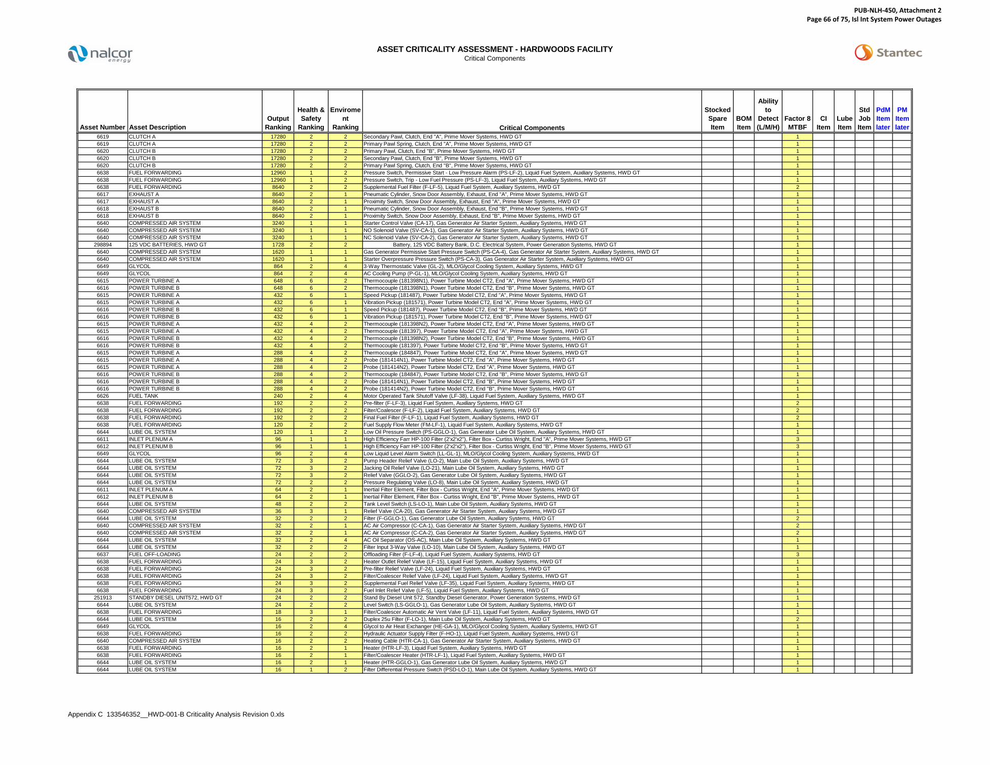
ASSET CRITICALITY ASSESSMENT - HARDWOODS FACILITYCritical Components
Appendix C 133546352__HWD-001-B Criticality Analysis Revision 0.xls
Asset Number Asset DescriptionOutput
Ranking
Health & Safety
Ranking
Enviroment
Ranking
Stocked Spare Item
BOM Item
Ability to
Detect (L/M/H)
Factor 8MTBF
CI Item
Lube Item
Std Job Item
PdM Itemlater
PM ItemlaterCritical Components
6619 CLUTCH A 17280 2 2 Secondary Pawl, Clutch, End "A", Prime Mover Systems, HWD GT 16619 CLUTCH A 17280 2 2 Primary Pawl Spring, Clutch, End "A", Prime Mover Systems, HWD GT 16620 CLUTCH B 17280 2 2 Primary Pawl, Clutch, End "B", Prime Mover Systems, HWD GT 16620 CLUTCH B 17280 2 2 Secondary Pawl, Clutch, End "B", Prime Mover Systems, HWD GT 16620 CLUTCH B 17280 2 2 Primary Pawl Spring, Clutch, End "B", Prime Mover Systems, HWD GT 16638 FUEL FORWARDING 12960 1 2 Pressure Switch, Permissive Start - Low Pressure Alarm (PS-LF-2), Liquid Fuel System, Auxiliary Systems, HWD GT 16638 FUEL FORWARDING 12960 1 2 Pressure Switch, Trip - Low Fuel Pressure (PS-LF-3), Liquid Fuel System, Auxiliary Systems, HWD GT 16638 FUEL FORWARDING 8640 2 2 Supplemental Fuel Filter (F-LF-5), Liquid Fuel System, Auxiliary Systems, HWD GT 26617 EXHAUST A 8640 2 1 Pneumatic Cylinder, Snow Door Assembly, Exhaust, End "A", Prime Mover Systems, HWD GT 16617 EXHAUST A 8640 2 1 Proximity Switch, Snow Door Assembly, Exhaust, End "A", Prime Mover Systems, HWD GT 16618 EXHAUST B 8640 2 1 Pneumatic Cylinder, Snow Door Assembly, Exhaust, End "B", Prime Mover Systems, HWD GT 16618 EXHAUST B 8640 2 1 Proximity Switch, Snow Door Assembly, Exhaust, End "B", Prime Mover Systems, HWD GT 16640 COMPRESSED AIR SYSTEM 3240 1 1 Starter Control Valve (CA-17), Gas Generator Air Starter System, Auxiliary Systems, HWD GT 16640 COMPRESSED AIR SYSTEM 3240 1 1 NO Solenoid Valve (SV-CA-1), Gas Generator Air Starter System, Auxiliary Systems, HWD GT 16640 COMPRESSED AIR SYSTEM 3240 1 1 NC Solenoid Valve (SV-CA-2), Gas Generator Air Starter System, Auxiliary Systems, HWD GT 1
298894 125 VDC BATTERIES, HWD GT 1728 2 2 Battery, 125 VDC Battery Bank, D.C. Electrical System, Power Generation Systems, HWD GT 16640 COMPRESSED AIR SYSTEM 1620 1 1 Gas Generator Permissive Start Pressure Switch (PS-CA-4), Gas Generator Air Starter System, Auxiliary Systems, HWD GT 16640 COMPRESSED AIR SYSTEM 1620 1 1 Starter Overpressure Pressure Switch (PS-CA-3), Gas Generator Air Starter System, Auxiliary Systems, HWD GT 16649 GLYCOL 864 2 4 3-Way Thermostatic Valve (GL-2), MLO/Glycol Cooling System, Auxiliary Systems, HWD GT 16649 GLYCOL 864 2 4 AC Cooling Pump (P-GL-1), MLO/Glycol Cooling System, Auxiliary Systems, HWD GT 16615 POWER TURBINE A 648 6 2 Thermocouple (181398N1), Power Turbine Model CT2, End "A", Prime Mover Systems, HWD GT 16616 POWER TURBINE B 648 6 2 Thermocouple (181398N1), Power Turbine Model CT2, End "B", Prime Mover Systems, HWD GT 16615 POWER TURBINE A 432 6 1 Speed Pickup (181487), Power Turbine Model CT2, End "A", Prime Mover Systems, HWD GT 16615 POWER TURBINE A 432 6 1 Vibration Pickup (181571), Power Turbine Model CT2, End "A", Prime Mover Systems, HWD GT 16616 POWER TURBINE B 432 6 1 Speed Pickup (181487), Power Turbine Model CT2, End "B", Prime Mover Systems, HWD GT 16616 POWER TURBINE B 432 6 1 Vibration Pickup (181571), Power Turbine Model CT2, End "B", Prime Mover Systems, HWD GT 16615 POWER TURBINE A 432 4 2 Thermocouple (181398N2), Power Turbine Model CT2, End "A", Prime Mover Systems, HWD GT 16615 POWER TURBINE A 432 4 2 Thermocouple (181397), Power Turbine Model CT2, End "A", Prime Mover Systems, HWD GT 16616 POWER TURBINE B 432 4 2 Thermocouple (181398N2), Power Turbine Model CT2, End "B", Prime Mover Systems, HWD GT 16616 POWER TURBINE B 432 4 2 Thermocouple (181397), Power Turbine Model CT2, End "B", Prime Mover Systems, HWD GT 16615 POWER TURBINE A 288 4 2 Thermocouple (184847), Power Turbine Model CT2, End "A", Prime Mover Systems, HWD GT 16615 POWER TURBINE A 288 4 2 Probe (181414N1), Power Turbine Model CT2, End "A", Prime Mover Systems, HWD GT 16615 POWER TURBINE A 288 4 2 Probe (181414N2), Power Turbine Model CT2, End "A", Prime Mover Systems, HWD GT 16616 POWER TURBINE B 288 4 2 Thermocouple (184847), Power Turbine Model CT2, End "B", Prime Mover Systems, HWD GT 16616 POWER TURBINE B 288 4 2 Probe (181414N1), Power Turbine Model CT2, End "B", Prime Mover Systems, HWD GT 16616 POWER TURBINE B 288 4 2 Probe (181414N2), Power Turbine Model CT2, End "B", Prime Mover Systems, HWD GT 16626 FUEL TANK 240 2 4 Motor Operated Tank Shutoff Valve (LF-38), Liquid Fuel System, Auxiliary Systems, HWD GT 16638 FUEL FORWARDING 192 2 2 Pre-filter (F-LF-3), Liquid Fuel System, Auxiliary Systems, HWD GT 26638 FUEL FORWARDING 192 2 2 Filter/Coalescer (F-LF-2), Liquid Fuel System, Auxiliary Systems, HWD GT 26638 FUEL FORWARDING 192 2 2 Final Fuel Filter (F-LF-1), Liquid Fuel System, Auxiliary Systems, HWD GT 26638 FUEL FORWARDING 120 2 2 Fuel Supply Flow Meter (FM-LF-1), Liquid Fuel System, Auxiliary Systems, HWD GT 16644 LUBE OIL SYSTEM 120 1 2 Low Oil Pressure Switch (PS-GGLO-1), Gas Generator Lube Oil System, Auxiliary Systems, HWD GT 16611 INLET PLENUM A 96 1 1 High Efficiency Farr HP-100 Filter (2'x2'x2"), Filter Box - Curtiss Wright, End "A", Prime Mover Systems, HWD GT 36612 INLET PLENUM B 96 1 1 High Efficiency Farr HP-100 Filter (2'x2'x2"), Filter Box - Curtiss Wright, End "B", Prime Mover Systems, HWD GT 36649 GLYCOL 96 2 4 Low Liquid Level Alarm Switch (LL-GL-1), MLO/Glycol Cooling System, Auxiliary Systems, HWD GT 16644 LUBE OIL SYSTEM 72 3 2 Pump Header Relief Valve (LO-2), Main Lube Oil System, Auxiliary Systems, HWD GT 16644 LUBE OIL SYSTEM 72 3 2 Jacking Oil Relief Valve (LO-21), Main Lube Oil System, Auxiliary Systems, HWD GT 16644 LUBE OIL SYSTEM 72 3 2 Relief Valve (GGLO-2), Gas Generator Lube Oil System, Auxiliary Systems, HWD GT 16644 LUBE OIL SYSTEM 72 2 2 Pressure Regulating Valve (LO-8), Main Lube Oil System, Auxiliary Systems, HWD GT 16611 INLET PLENUM A 64 2 1 Inertial Filter Element, Filter Box - Curtiss Wright, End "A", Prime Mover Systems, HWD GT 16612 INLET PLENUM B 64 2 1 Inertial Filter Element, Filter Box - Curtiss Wright, End "B", Prime Mover Systems, HWD GT 16644 LUBE OIL SYSTEM 48 2 2 Tank Level Switch (LS-LO-1), Main Lube Oil System, Auxiliary Systems, HWD GT 16640 COMPRESSED AIR SYSTEM 36 3 1 Relief Valve (CA-20), Gas Generator Air Starter System, Auxiliary Systems, HWD GT 16644 LUBE OIL SYSTEM 32 2 2 Filter (F-GGLO-1), Gas Generator Lube Oil System, Auxiliary Systems, HWD GT 26640 COMPRESSED AIR SYSTEM 32 2 1 AC Air Compressor (C-CA-1), Gas Generator Air Starter System, Auxiliary Systems, HWD GT 26640 COMPRESSED AIR SYSTEM 32 2 1 AC Air Compressor (C-CA-2), Gas Generator Air Starter System, Auxiliary Systems, HWD GT 26644 LUBE OIL SYSTEM 32 2 4 AC Oil Separator (OS-AC), Main Lube Oil System, Auxiliary Systems, HWD GT 16644 LUBE OIL SYSTEM 32 2 2 Filter Input 3-Way Valve (LO-10), Main Lube Oil System, Auxiliary Systems, HWD GT 16637 FUEL OFF-LOADING 24 2 2 Offloading Filter (F-LF-4), Liquid Fuel System, Auxiliary Systems, HWD GT 36638 FUEL FORWARDING 24 3 2 Heater Outlet Relief Valve (LF-15), Liquid Fuel System, Auxiliary Systems, HWD GT 16638 FUEL FORWARDING 24 3 2 Pre-filter Relief Valve (LF-24), Liquid Fuel System, Auxiliary Systems, HWD GT 16638 FUEL FORWARDING 24 3 2 Filter/Coalescer Relief Valve (LF-24), Liquid Fuel System, Auxiliary Systems, HWD GT 16638 FUEL FORWARDING 24 3 2 Supplemental Fuel Relief Valve (LF-35), Liquid Fuel System, Auxiliary Systems, HWD GT 16638 FUEL FORWARDING 24 3 2 Fuel Inlet Relief Valve (LF-5), Liquid Fuel System, Auxiliary Systems, HWD GT 1
251913 STANDBY DIESEL UNIT572, HWD GT 24 2 2 Stand By Diesel Unit 572, Standby Diesel Generator, Power Generation Systems, HWD GT 16644 LUBE OIL SYSTEM 24 2 2 Level Switch (LS-GGLO-1), Gas Generator Lube Oil System, Auxiliary Systems, HWD GT 16638 FUEL FORWARDING 18 3 1 Filter/Coalescer Automatic Air Vent Valve (LF-11), Liquid Fuel System, Auxiliary Systems, HWD GT 16644 LUBE OIL SYSTEM 16 2 2 Duplex 25u Filter (F-LO-1), Main Lube Oil System, Auxiliary Systems, HWD GT 26649 GLYCOL 16 2 4 Glycol to Air Heat Exchanger (HE-GA-1), MLO/Glycol Cooling System, Auxiliary Systems, HWD GT 16638 FUEL FORWARDING 16 2 2 Hydraulic Actuator Supply Filter (F-HO-1), Liquid Fuel System, Auxiliary Systems, HWD GT 16640 COMPRESSED AIR SYSTEM 16 2 2 Heating Cable (HTR-CA-1), Gas Generator Air Starter System, Auxiliary Systems, HWD GT 16638 FUEL FORWARDING 16 2 1 Heater (HTR-LF-3), Liquid Fuel System, Auxiliary Systems, HWD GT 16638 FUEL FORWARDING 16 2 1 Filter/Coalescer Heater (HTR-LF-1), Liquid Fuel System, Auxiliary Systems, HWD GT 16644 LUBE OIL SYSTEM 16 2 1 Heater (HTR-GGLO-1), Gas Generator Lube Oil System, Auxiliary Systems, HWD GT 16644 LUBE OIL SYSTEM 16 1 2 Filter Differential Pressure Switch (PSD-LO-1), Main Lube Oil System, Auxiliary Systems, HWD GT 1
PUB-NLH-450, Attachment 2 Page 66 of 75, Isl Int System Power Outages

ASSET CRITICALITY ASSESSMENT - HARDWOODS FACILITYCritical Components
Appendix C 133546352__HWD-001-B Criticality Analysis Revision 0.xls
Asset Number Asset DescriptionOutput
Ranking
Health & Safety
Ranking
Enviroment
Ranking
Stocked Spare Item
BOM Item
Ability to
Detect (L/M/H)
Factor 8MTBF
CI Item
Lube Item
Std Job Item
PdM Itemlater
PM ItemlaterCritical Components
6644 LUBE OIL SYSTEM 16 1 2 Filter Upstream Pressure Switch (PS-GGLO-3), Gas Generator Lube Oil System, Auxiliary Systems, HWD GT 16637 FUEL OFF-LOADING 12 2 2 AC Pump (P&M-LF-4), Liquid Fuel System, Auxiliary Systems, HWD GT 16637 FUEL OFF-LOADING 12 2 2 AC Pump (P&M-LF-5), Liquid Fuel System, Auxiliary Systems, HWD GT 16637 FUEL OFF-LOADING 12 2 2 Offloading Flow Meter (FM-LF-2), Liquid Fuel System, Auxiliary Systems, HWD GT 16638 FUEL FORWARDING 12 2 2 AC Pump (P&M-LF-2), Liquid Fuel System, Auxiliary Systems, HWD GT 16638 FUEL FORWARDING 12 2 2 AC Pump (P&M-LF-3), Liquid Fuel System, Auxiliary Systems, HWD GT 16644 LUBE OIL SYSTEM 12 2 2 Main AC Pump (P-LO-1), Main Lube Oil System, Auxiliary Systems, HWD GT 16644 LUBE OIL SYSTEM 12 2 2 Auxiliary AC Pump (P-LO-2), Main Lube Oil System, Auxiliary Systems, HWD GT 16644 LUBE OIL SYSTEM 12 2 2 Emergency DC Pump (P-LO-3), Main Lube Oil System, Auxiliary Systems, HWD GT 16644 LUBE OIL SYSTEM 12 2 2 Emergency DC Pump (P-LO-4), Main Lube Oil System, Auxiliary Systems, HWD GT 16644 LUBE OIL SYSTEM 12 2 1 AC Evacuator Fan (EV-AC), Main Lube Oil System, Auxiliary Systems, HWD GT 16644 LUBE OIL SYSTEM 12 1 1 Heater Control Temperature Switch (TS-LO-1), Main Lube Oil System, Auxiliary Systems, HWD GT 16644 LUBE OIL SYSTEM 12 1 1 Heater Control Temperature Switch (TS-GGLO-1), Gas Generator Lube Oil System, Auxiliary Systems, HWD GT 16638 FUEL FORWARDING 8 2 2 Filter/Coalescer Automatic Drain Valve (LF-12), Liquid Fuel System, Auxiliary Systems, HWD GT 16638 FUEL FORWARDING 8 1 2 Pre-filter Differential Pressure Switch (PSD-LF-2), Liquid Fuel System, Auxiliary Systems, HWD GT 16638 FUEL FORWARDING 8 1 2 Final Fuel Filter Differential Pressure Switch (PSD-LF-A), Liquid Fuel System, Auxiliary Systems, HWD GT 16640 COMPRESSED AIR SYSTEM 6 3 1 Air Compressor Relief Valve (CA-14), Gas Generator Air Starter System, Auxiliary Systems, HWD GT 16640 COMPRESSED AIR SYSTEM 6 3 1 Air Receiver Relief Valve (CA-13), Gas Generator Air Starter System, Auxiliary Systems, HWD GT 16644 LUBE OIL SYSTEM 4 2 1 Oil Heater (HTR-LO-1), Main Lube Oil System, Auxiliary Systems, HWD GT 16638 FUEL FORWARDING 4 1 2 AC Pump Discharge Fuel Pressure Switch (PS-LF-1), Liquid Fuel System, Auxiliary Systems, HWD GT 16638 FUEL FORWARDING 4 1 2 AC Pump Discharge Fuel Pressure Switch (PS-LF-4), Liquid Fuel System, Auxiliary Systems, HWD GT 16638 FUEL FORWARDING 4 1 2 Fuel Pressure Transducer (PT-LF-1), Liquid Fuel System, Auxiliary Systems, HWD GT 16638 FUEL FORWARDING 4 1 2 P3 Pressure Transducer (PT-P3-1), Liquid Fuel System, Auxiliary Systems, HWD GT 16638 FUEL FORWARDING 4 1 2 Pressure Switch (PS-HO-1), Liquid Fuel System, Auxiliary Systems, HWD GT 16644 LUBE OIL SYSTEM 4 1 2 DC Pump Start Pressure Switch (PS-LO-3), Main Lube Oil System, Auxiliary Systems, HWD GT 16644 LUBE OIL SYSTEM 4 1 2 Low Oil Pressure Switch (PS-GGLO-2), Gas Generator Lube Oil System, Auxiliary Systems, HWD GT 1
298852 24 VDC BATT CHG, DIESEL, HWD 4 1 1 24 VDC Battery Charger, Standby Diesel Generator, Power Generation Systems, HWD GT 1298851 125 VDC BATT CHG, DIESEL, HWD 4 1 1 125 VDC Battery Charger, D.C. Electrical System, Power Generation Systems, HWD GT 16638 FUEL FORWARDING 4 1 1 Fuel Supply Thermocouple (TC-LF-1), Liquid Fuel System, Auxiliary Systems, STV GT 16640 COMPRESSED AIR SYSTEM 4 1 1 Automatic Condensate Drain Trap (DT-CA-1), Gas Generator Air Starter System, Auxiliary Systems, HWD GT 16640 COMPRESSED AIR SYSTEM 4 1 1 NC Solenoid Valve (SV-CA-3), Gas Generator Air Starter System, Auxiliary Systems, HWD GT 16640 COMPRESSED AIR SYSTEM 4 1 1 Air Regulator (CA-17-A), Gas Generator Air Starter System, Auxiliary Systems, HWD GT 16640 COMPRESSED AIR SYSTEM 4 1 1 Air Regulator (CA-17-B), Gas Generator Air Starter System, Auxiliary Systems, HWD GT 16611 INLET PLENUM A 2 2 1 Blow-In Doors Limit Switch, Filter Box - Curtiss Wright, End "A", Prime Mover Systems, HWD GT 16611 INLET PLENUM A 2 2 1 Blow-In Doors Differential Pressure Switch, Filter Box - Curtiss Wright, End "A", Prime Mover Systems, HWD GT 16612 INLET PLENUM B 2 2 1 Blow-In Doors Limit Switch, Filter Box - Curtiss Wright, End "B", Prime Mover Systems, HWD GT 16612 INLET PLENUM B 2 2 1 Blow-In Doors Differential Pressure Switch, Filter Box - Curtiss Wright, End "B", Prime Mover Systems, HWD GT 16638 FUEL FORWARDING 2 1 1 Fuel Temperature Sensor (TS-LF-1), Liquid Fuel System, Auxiliary Systems, HWD GT 16644 LUBE OIL SYSTEM 2 1 1 Oil Supply Thermocouple (TC-LO-1), Main Lube Oil System, Auxiliary Systems, HWD GT 16644 LUBE OIL SYSTEM 2 1 1 Oil Drain Thermocouple (TC-LO-2), Main Lube Oil System, Auxiliary Systems, HWD GT 16644 LUBE OIL SYSTEM 2 1 1 Alternator Bearing Drain Oil Thermocouple (TC-LO-3), Main Lube Oil System, Auxiliary Systems, HWD GT 16644 LUBE OIL SYSTEM 2 1 1 Oil Supply Thermocouple (TC-GGLO-1), Gas Generator Lube Oil System, Auxiliary Systems, HWD GT 16640 COMPRESSED AIR SYSTEM 2 1 1 Compressor Start-Stop Pressure Switch (PS-CA-1), Gas Generator Air Starter System, Auxiliary Systems, HWD GT 16640 COMPRESSED AIR SYSTEM 2 1 1 Compressor Start-Stop Pressure Switch (PS-CA-2), Gas Generator Air Starter System, Auxiliary Systems, HWD GT 16640 COMPRESSED AIR SYSTEM 2 1 1 Snubber (SN-CA-1), Gas Generator Air Starter System, Auxiliary Systems, HWD GT 16640 COMPRESSED AIR SYSTEM 2 1 1 Control Air Dryer (F-CA-1), Gas Generator Air Starter System, Auxiliary Systems, HWD GT 16611 INLET PLENUM A 1 1 1 Inlet Temperature Thermocouple, Gas Generator Enclosure with Septum Doors, End "A", Prime Mover Systems, HWD GT 16611 INLET PLENUM A 1 1 1 Inlet Pressure Transducer, Gas Generator Enclosure with Septum Doors, End "A", Prime Mover Systems, HWD GT 16611 INLET PLENUM A 1 1 1 Resistance Temperature Detector Probe, Gas Generator Enclosure with Septum Doors, End "A", Prime Mover Systems, HWD GT 16612 INLET PLENUM B 1 1 1 Inlet Temperature Thermocouple, Gas Generator Enclosure with Septum Doors, End "B", Prime Mover Systems, HWD GT 16612 INLET PLENUM B 1 1 1 Inlet Pressure Transducer, Gas Generator Enclosure with Septum Doors, End "B", Prime Mover Systems, HWD GT 16612 INLET PLENUM B 1 1 1 Resistance Temperature Detector Probe, Gas Generator Enclosure with Septum Doors, End "B", Prime Mover Systems, HWD GT 1
PUB-NLH-450, Attachment 2 Page 67 of 75, Isl Int System Power Outages

ASSET CRITICALITY ASSESSMENT - STEPHENVILLE FACILITY
Appendix C 133546352__STV-001-B Criticality Analysis Revision 0.xls Page 1 of 8
Document No.: STV-001-B
Revision Date By Approveda 18-Jul-14 BM -b 8-Aug-14 BM -0 4-Sep-14 BM -
Inst
ance
s pe
r A
ssem
bly
Fact
or 1
Hea
lth &
Sa
fety
Fact
or 2
Out
put
Fact
or 3
Qua
lity
Fact
or 4
Util
izat
ion
Fact
or 5
A
ltern
ativ
es
Fact
or 6
Envi
ronm
ent
Fact
or 7
Tim
e to
Effe
ct
Fact
or 8
Cus
tom
er
Impa
cts
Fact
or 9
Loss
Typ
e
EquipmentScore Fa
ctor
10
MTB
F
Fact
or 1
1En
gine
erin
g C
ost
Bre
akdo
wn
Fact
or 1
2Ef
fect
of
Was
te o
r En
ergy
Los
s
AdditionalFactor Score
CriticalityScore
CriticalityCategory
A1 A2 A3 A4 A5 C1 C2
PRIME MOVER SYSTEMS, STV GTEND "A", PRIME MOVER SYSTEMS, STV GT 1
Filter Box - Curtiss Wright (Dwg. 120-D-10562, Sheet 12/13), End "A", Prime Mover Systems, STV GT 1 2 2 2 1 2 1 1 1 1 16 1 2 2 4 64Inertial Filter Element, Filter Box - Curtiss Wright, End "A", Prime Mover Systems, STV GT 24 2 2 2 1 2 1 1 1 1 16 1 2 2 4 64High Efficiency Farr HP-100 Filter (2'x2'x2"), Filter Box - Curtiss Wright, End "A", Prime Mover Systems, STV GT 1 2 2 1 2 1 1 1 1 8 3 2 2 12 96Blow-In Doors Limit Switch, Filter Box - Curtiss Wright, End "A", Prime Mover Systems, STV GT 2 2 1 1 1 1 1 1 1 1 2 1 1 1 1 2Blow-In Doors Differential Pressure Switch, Filter Box - Curtiss Wright, End "A", Prime Mover Systems, STV GT 1 2 1 1 1 1 1 1 1 1 2 1 1 1 1 2
Gas Generator Enclosure with Septum Doors (Dwg. 120-D-10562, Sheet 6/13), End "A", Prime Mover Systems, STV GT 1 1 1 1 1 1 1 1 1 1 1 1 1 1 1 1Inlet Temperature Thermocouple, Gas Generator Enclosure with Septum Doors, End "A", Prime Mover Systems, STV GT 1 1 1 1 1 1 1 1 1 1 1 1 1 1 1 1Inlet Pressure Transducer, Gas Generator Enclosure with Septum Doors, End "A", Prime Mover Systems, STV GT 1 1 1 1 1 1 1 1 1 1 1 1 1 1 1 1Resistance Temperature Detector Probe, Gas Generator Enclosure with Septum Doors, End "A", Prime Mover Systems, STV GT 1 1 1 1 1 1 1 1 1 1 1 1 1 1 1 1
Gas Generator (Docs. RR Olympus C Parts Catalogue), End "A", Prime Mover Systems, STV GT 1 6 8 3 1 2 2 5 1 5 14400 4 3 3 36 518400Liquid Fuel Burner - Complete (BDC.3026), Gas Generator, End "A", Prime Mover Systems, STV GT 8 6 8 3 1 6 2 5 1 5 43200 4 3 3 36 1555200Combustion Chamber, Gas Generator, End "A", Prime Mover Systems, STV GT 8 6 8 3 1 6 2 5 1 5 43200 4 3 3 36 1555200Anti-Icing Hot Air Valve - Complete (810-501-0747), Gas Generator, End "A", Prime Mover Systems, STV GT 1 6 4 3 1 6 1 4 1 5 8640 5 3 3 45 388800Fuel Filter, Gas Generator, Prime Mover Systems, STV GT 1 6 4 3 1 4 2 4 1 5 11520 4 2 2 16 184320Upper Fuel Pump Assembly, Gas Generator, End "A", Prime Mover Systems, STV GT 1 6 8 3 1 6 2 5 1 5 43200 4 3 3 36 1555200Lower Fuel Pump Assembly, Gas Generator, End "A", Prime Mover Systems, STV GT 1 6 8 3 1 6 2 5 1 5 43200 4 3 3 36 1555200Outer Fuel Pump Drive Assembly (BDA.7591), Gas Generator, End "A", Prime Mover Systems, STV GT 1 6 8 3 1 6 2 5 1 5 43200 4 3 3 36 1555200Oil Filter Unit - Complete (B.108506), Gas Generator, End "A", Prime Mover Systems, STV GT 1 6 4 3 1 4 2 4 1 5 11520 4 2 2 16 184320Oil Pump - Complete, Gas Generator, End "A", Prime Mover Systems, STV GT 1 6 8 3 1 6 2 5 1 5 43200 4 3 3 36 1555200Outer Oil Pump Drive Assembly (47-1-1-006409), Gas Generator, End "A", Prime Mover Systems, STV GT 1 6 8 3 1 6 2 5 1 5 43200 4 3 3 36 1555200Scavenge Pump Assembly (47-1-1-006418), Gas Generator, End "A", Prime Mover Systems, STV GT 1 6 8 3 1 6 2 5 1 5 43200 4 3 3 36 1555200Outer Starter Drive Assembly (BDA.1153), Gas Generator, End "A", Prime Mover Systems, STV GT 1 6 8 3 1 6 2 5 1 5 43200 4 3 3 36 1555200LP Compressor Magnetic Pickup, Gas Generator, End "A", Prime Mover Systems, STV GT 6 4 3 1 6 1 5 1 5 10800 4 2 3 24 259200HP Compressor Magnetic Pickup, Gas Generator, End "A", Prime Mover Systems, STV GT 6 4 3 1 6 1 5 1 5 10800 4 2 3 24 259200Vibration Transducer, Gas Generator, End "A", Prime Mover Systems, STV GT 6 4 3 1 6 1 5 1 5 10800 4 2 3 24 259200High Energy Ignition Unit, Gas Generator, End "A", Prime Mover Systems, STV GT 6 8 3 1 6 1 5 1 5 21600 4 3 3 36 777600
Power Turbine Model CT2 (Dwg. 494005N), End "A", Prime Mover Systems, STV GT 1 6 8 3 1 2 2 5 1 5 14400 1 4 3 12 172800Thermocouple (181398N1), Power Turbine Model CT2, End "A", Prime Mover Systems, STV GT 1 6 3 2 1 3 2 1 1 1 216 1 3 1 3 648Thermocouple (181398N2), Power Turbine Model CT2, End "A", Prime Mover Systems, STV GT 1 4 3 2 1 3 2 1 1 1 144 1 3 1 3 432Thermocouple (184847), Power Turbine Model CT2, End "A", Prime Mover Systems, STV GT 8 4 3 2 1 3 2 1 1 1 144 1 2 1 2 288Probe (181414N1), Power Turbine Model CT2, End "A", Prime Mover Systems, STV GT 1 4 3 2 1 3 2 1 1 1 144 1 2 1 2 288Probe (181414N2), Power Turbine Model CT2, End "A", Prime Mover Systems, STV GT 1 4 3 2 1 3 2 1 1 1 144 1 2 1 2 288Speed Pickup (181487), Power Turbine Model CT2, End "A", Prime Mover Systems, STV GT 1 6 3 1 1 6 1 1 1 1 108 1 4 1 4 432Vibration Pickup (181571), Power Turbine Model CT2, End "A", Prime Mover Systems, STV GT 1 6 3 1 1 6 1 1 1 1 108 1 4 1 4 432Bearing (181413 or 181332), Power Turbine Model CT2, End "A", Prime Mover Systems, STV GT 1 6 8 3 1 6 2 5 1 3 25920 1 4 3 12 311040Bearing (494047), Power Turbine Model CT2, End "A", Prime Mover Systems, STV GT 1 6 8 3 1 6 2 5 1 3 25920 1 4 3 12 311040Bearing (494056), Power Turbine Model CT2, End "A", Prime Mover Systems, STV GT 1 6 8 3 1 6 2 5 1 3 25920 1 4 3 12 311040Thermocouple (181397), Power Turbine Model CT2, End "A", Prime Mover Systems, STV GT 1 4 3 2 1 3 2 1 1 1 144 1 3 1 3 432Valve (181536), Power Turbine Model CT2, End "A", Prime Mover Systems, STV GT 1 4 4 3 1 6 1 5 1 3 4320 1 2 3 6 25920Filter (494064), Power Turbine Model CT2, End "A", Prime Mover Systems, STV GT 1 4 4 3 1 4 2 4 1 5 7680 4 2 2 16 122880
Exhaust, End "A", Prime Mover Systems, STV GT 1 2 8 3 1 2 1 2 1 5 960 3 2 3 18 17280Snow Door Assembly (Dwg. A-14-D-1459-04), Exhaust, End "A", Prime Mover Systems, STV GT 1 2 8 3 1 2 1 5 1 3 1440 1 2 3 6 8640
Double-Acting Pneumatic Cylinder, Snow Door Assembly, Exhaust, End "A", Prime Mover Systems, STV GT 4 2 8 3 1 2 1 5 1 3 1440 1 2 3 6 8640Limit Switch, Snow Door Assembly, Exhaust, End "A", Prime Mover Systems, STV GT 4 2 8 3 1 2 1 5 1 3 1440 1 2 3 6 8640
Clutch (Dwg. SL13341), End "A", Prime Mover Systems, STV GT 1 2 8 3 1 2 2 5 1 5 4800 5 2 3 30 144000Primary Ratchet Ring, Clutch, End "A", Prime Mover Systems, STV GT 1 2 8 3 1 2 2 5 1 3 2880 1 3 3 9 25920Secondary Ratchet Ring, Clutch, End "A", Prime Mover Systems, STV GT 1 2 8 3 1 2 2 5 1 3 2880 1 3 3 9 25920Primary Pawl, Clutch, End "A", Prime Mover Systems, STV GT 4 2 8 3 1 2 2 5 1 3 2880 1 2 3 6 17280Secondary Pawl, Clutch, End "A", Prime Mover Systems, STV GT 4 2 8 3 1 2 2 5 1 3 2880 1 2 3 6 17280Primary Pawl Spring, Clutch, End "A", Prime Mover Systems, STV GT 4 2 8 3 1 2 2 5 1 3 2880 1 2 3 6 17280Proximity Switch, Clutch, End "A", Prime Mover Systems, STV GT 1 2 8 3 1 2 2 5 1 3 2880 5 2 3 30 86400
END "B", PRIME MOVER SYSTEMS, STV GT 1Filter Box - Curtiss Wright (Dwg. 120-D-10562, Sheet 12/13), End "B", Prime Mover Systems, STV GT 1 2 2 2 1 2 1 1 1 1 16 1 2 2 4 64
Inertial Filter Element, Filter Box - Curtiss Wright, End "B", Prime Mover Systems, STV GT 24 2 2 2 1 2 1 1 1 1 16 1 2 2 4 64High Efficiency Farr HP-100 Filter (2'x2'x2"), Filter Box - Curtiss Wright, End "B", Prime Mover Systems, STV GT 1 2 2 1 2 1 1 1 1 8 3 2 2 12 96Blow-In Doors Limit Switch, Filter Box - Curtiss Wright, End "B", Prime Mover Systems, STV GT 2 2 1 1 1 1 1 1 1 1 2 1 1 1 1 2Blow-In Doors Differential Pressure Switch, Filter Box - Curtiss Wright, End "B", Prime Mover Systems, STV GT 1 2 1 1 1 1 1 1 1 1 2 1 1 1 1 2
Gas Generator Enclosure with Septum Doors (Dwg. 120-D-10562, Sheet 6/13), End "B", Prime Mover Systems, STV GT 1 1 1 1 1 1 1 1 1 1 1 1 1 1 1 1Inlet Temperature Thermocouple, Gas Generator Enclosure with Septum Doors, End "B", Prime Mover Systems, STV GT 1 1 1 1 1 1 1 1 1 1 1 1 1 1 1 1Inlet Pressure Transducer, Gas Generator Enclosure with Septum Doors, End "B", Prime Mover Systems, STV GT 1 1 1 1 1 1 1 1 1 1 1 1 1 1 1 1Resistance Temperature Detector Probe, Gas Generator Enclosure with Septum Doors, End "B", Prime Mover Systems, STV GT 1 1 1 1 1 1 1 1 1 1 1 1 1 1 1 1
Gas Generator (Docs. RR Olympus C Parts Catalogue), End "B", Prime Mover Systems, STV GT 1 6 8 3 1 2 2 5 1 5 14400 4 3 3 36 518400Liquid Fuel Burner - Complete (BDC.3026), Gas Generator, End "B", Prime Mover Systems, STV GT 8 6 8 3 1 6 2 5 1 5 43200 4 3 3 36 1555200Combustion Chamber, Gas Generator, End "B", Prime Mover Systems, STV GT 8 6 8 3 1 6 2 5 1 5 43200 4 3 3 36 1555200Anti-Icing Hot Air Valve - Complete (810-501-0747), Gas Generator, End "B", Prime Mover Systems, STV GT 1 6 4 3 1 6 1 4 1 5 8640 5 3 3 45 388800Fuel Filter, Gas Generator, Prime Mover Systems, STV GT 1 6 4 3 1 4 2 4 1 5 11520 4 2 2 16 184320Upper Fuel Pump Assembly, Gas Generator, End "B", Prime Mover Systems, STV GT 1 6 8 3 1 6 2 5 1 5 43200 4 3 3 36 1555200Lower Fuel Pump Assembly, Gas Generator, End "B", Prime Mover Systems, STV GT 1 6 8 3 1 6 2 5 1 5 43200 4 3 3 36 1555200Outer Fuel Pump Drive Assembly (BDA.7591), Gas Generator, End "B", Prime Mover Systems, STV GT 1 6 8 3 1 6 2 5 1 5 43200 4 3 3 36 1555200
Equipment Name
DescriptionIssued for ReviewPreliminary Milestone Issue - For ReviewIssued for Final Report
PUB-NLH-450, Attachment 2 Page 68 of 75, Isl Int System Power Outages

ASSET CRITICALITY ASSESSMENT - STEPHENVILLE FACILITY
Appendix C 133546352__STV-001-B Criticality Analysis Revision 0.xls Page 2 of 8
Inst
ance
s pe
r A
ssem
bly
Fact
or 1
Hea
lth &
Sa
fety
Fact
or 2
Out
put
Fact
or 3
Qua
lity
Fact
or 4
Util
izat
ion
Fact
or 5
A
ltern
ativ
es
Fact
or 6
Envi
ronm
ent
Fact
or 7
Tim
e to
Effe
ct
Fact
or 8
Cus
tom
er
Impa
cts
Fact
or 9
Loss
Typ
e
EquipmentScore Fa
ctor
10
MTB
F
Fact
or 1
1En
gine
erin
g C
ost
Bre
akdo
wn
Fact
or 1
2Ef
fect
of
Was
te o
r En
ergy
Los
s
AdditionalFactor Score
CriticalityScore
CriticalityCategoryEquipment Name
Oil Filter Unit - Complete (B.108506), Gas Generator, End "B", Prime Mover Systems, STV GT 1 6 4 3 1 4 2 4 1 5 11520 4 2 2 16 184320Oil Pump - Complete, Gas Generator, End "B", Prime Mover Systems, STV GT 1 6 8 3 1 6 2 5 1 5 43200 4 3 3 36 1555200Outer Oil Pump Drive Assembly (47-1-1-006409), Gas Generator, End "B", Prime Mover Systems, STV GT 1 6 8 3 1 6 2 5 1 5 43200 4 3 3 36 1555200Scavenge Pump Assembly (47-1-1-006418), Gas Generator, End "B", Prime Mover Systems, STV GT 1 6 8 3 1 6 2 5 1 5 43200 4 3 3 36 1555200Outer Starter Drive Assembly (BDA.1153), Gas Generator, End "B", Prime Mover Systems, STV GT 1 6 8 3 1 6 2 5 1 5 43200 4 3 3 36 1555200LP Compressor Magnetic Pickup, Gas Generator, End "B", Prime Mover Systems, STV GT 6 4 3 1 6 1 5 1 5 10800 4 2 3 24 259200HP Compressor Magnetic Pickup, Gas Generator, End "B", Prime Mover Systems, STV GT 6 4 3 1 6 1 5 1 5 10800 4 2 3 24 259200Vibration Transducer, Gas Generator, End "B", Prime Mover Systems, STV GT 6 4 3 1 6 1 5 1 5 10800 4 2 3 24 259200High Energy Ignition Unit, Gas Generator, End "B", Prime Mover Systems, STV GT 6 8 3 1 6 1 5 1 5 21600 4 3 3 36 777600
Power Turbine Model CT2 (Dwg. 494005N), End "B", Prime Mover Systems, STV GT 1 6 8 3 1 2 2 5 1 5 14400 1 4 3 12 172800Thermocouple (181398N1), Power Turbine Model CT2, End "B", Prime Mover Systems, STV GT 1 6 3 2 1 3 2 1 1 1 216 1 3 1 3 648Thermocouple (181398N2), Power Turbine Model CT2, End "B", Prime Mover Systems, STV GT 1 4 3 2 1 3 2 1 1 1 144 1 3 1 3 432Thermocouple (184847), Power Turbine Model CT2, End "B", Prime Mover Systems, STV GT 8 4 3 2 1 3 2 1 1 1 144 1 2 1 2 288Probe (181414N1), Power Turbine Model CT2, End "B", Prime Mover Systems, STV GT 1 4 3 2 1 3 2 1 1 1 144 1 2 1 2 288Probe (181414N2), Power Turbine Model CT2, End "B", Prime Mover Systems, STV GT 1 4 3 2 1 3 2 1 1 1 144 1 2 1 2 288Speed Pickup (181487), Power Turbine Model CT2, End "B", Prime Mover Systems, STV GT 1 6 3 1 1 6 1 1 1 1 108 1 4 1 4 432Vibration Pickup (181571), Power Turbine Model CT2, End "B", Prime Mover Systems, STV GT 1 6 3 1 1 6 1 1 1 1 108 1 4 1 4 432Bearing (181413 or 181332), Power Turbine Model CT2, End "B", Prime Mover Systems, STV GT 1 6 8 3 1 6 2 5 1 3 25920 1 4 3 12 311040Bearing (494047), Power Turbine Model CT2, End "B", Prime Mover Systems, STV GT 1 6 8 3 1 6 2 5 1 3 25920 1 4 3 12 311040Bearing (494056), Power Turbine Model CT2, End "B", Prime Mover Systems, STV GT 1 6 8 3 1 6 2 5 1 3 25920 1 4 3 12 311040Thermocouple (181397), Power Turbine Model CT2, End "B", Prime Mover Systems, STV GT 1 4 3 2 1 3 2 1 1 1 144 1 3 1 3 432Valve (181536), Power Turbine Model CT2, End "B", Prime Mover Systems, STV GT 1 4 4 3 1 6 1 5 1 3 4320 1 2 3 6 25920Filter (494064), Power Turbine Model CT2, End "B", Prime Mover Systems, STV GT 1 4 4 3 1 4 2 4 1 5 7680 4 2 2 16 122880
Exhaust, End "B", Prime Mover Systems, STV GT 1 2 8 3 1 2 1 2 1 5 960 3 2 3 18 17280Snow Door Assembly (Dwg. A-14-D-1459-04), Exhaust, End "B", Prime Mover Systems, STV GT 1 2 8 3 1 2 1 5 1 3 1440 1 2 3 6 8640
Double-Acting Pneumatic Cylinder, Snow Door Assembly, Exhaust, End "B", Prime Mover Systems, STV GT 4 2 8 3 1 2 1 5 1 3 1440 1 2 3 6 8640Limit Switch, Snow Door Assembly, Exhaust, End "B", Prime Mover Systems, STV GT 4 2 8 3 1 2 1 5 1 3 1440 1 2 3 6 8640
Clutch (Dwg. SL13341), End "B", Prime Mover Systems, STV GT 1 2 8 3 1 2 2 5 1 5 4800 5 2 3 30 144000Primary Ratchet Ring, Clutch, End "B", Prime Mover Systems, STV GT 1 2 8 3 1 2 2 5 1 3 2880 1 3 3 9 25920Secondary Ratchet Ring, Clutch, End "B", Prime Mover Systems, STV GT 1 2 8 3 1 2 2 5 1 3 2880 1 3 3 9 25920Primary Pawl, Clutch, End "B", Prime Mover Systems, STV GT 4 2 8 3 1 2 2 5 1 3 2880 1 2 3 6 17280Secondary Pawl, Clutch, End "B", Prime Mover Systems, STV GT 4 2 8 3 1 2 2 5 1 3 2880 1 2 3 6 17280Primary Pawl Spring, Clutch, End "B", Prime Mover Systems, STV GT 4 2 8 3 1 2 2 5 1 3 2880 1 2 3 6 17280Proximity Switch, Clutch, End "B", Prime Mover Systems, STV GT 1 2 8 3 1 2 2 5 1 3 2880 5 2 3 30 86400
POWER GENERATION SYSTEMS, STV GT63 MVA 50 MW GENERATOR (Dwg. A03122987), POWER GENERATION SYSTEMS, STV GT 1 1 8 3 1 6 2 5 3 5 21600 1 5 4 20 432000
Exciter Bearing, 63MVA 50MW Generator, Power Generation Systems, STV GT 1 1 8 3 1 6 2 5 3 5 21600 1 4 4 16 345600Rotor Bearing, 63MVA 50MW Generator, Power Generation Systems, STV GT 1 1 8 3 1 6 2 5 3 5 21600 1 4 4 16 345600Grounding Transformer, 63MVA 50MW Generator, Power Generation Systems, STV GT 1 8 3 1 6 4 5 3 5 43200 1 3 4 12 518400Potential Transformers, 63MVA 50MW Generator, Power Generation Systems, STV GT 1 8 3 1 6 4 5 3 5 43200 1 3 4 12 518400Current Transformers, 63MVA 50MW Generator, Power Generation Systems, STV GT 1 8 3 1 6 4 5 3 5 43200 1 3 4 12 518400
STANDBY DIESEL GENERATOR, POWER GENERATION SYSTEMS, STV GT 1 2 1 1 1 2 2 1 1 1 8 1 3 1 3 24Stand By Diesel Unit 572, Standby Diesel Generator, Power Generation Systems, STV GT 1 2 1 1 1 2 2 1 1 1 8 1 3 1 3 2424 VDC Battery Charger, Standby Diesel Generator, Power Generation Systems, STV GT 1 1 1 1 1 2 1 1 1 1 2 1 2 1 2 4
A.C. ELECTRICAL SYSTEM, POWER GENERATION SYSTEMS, STV GT 1 4 3 3 1 2 1 5 1 5 1800 1 3 3 9 16200Station Service Transformer, A.C. Electrical System, Power Generation Systems, STV GTUnit Transformer, A.C. Electrical System, Power Generation Systems, STV GTGenerator Transformer, A.C. Electrical System, Power Generation Systems, STV GTDisconnect Breakers (Station Service/Generator), A.C. Electrical System, Power Generation Systems, STV GTUnit Control (DCS), A.C. Electrical System, Power Generation Systems, STV GTMain Breaker G1T5, A.C. Electrical System, Power Generation Systems, STV GTUnit Relaying, A.C. Electrical System, Power Generation Systems, STV GTVibration Protection, A.C. Electrical System, Power Generation Systems, STV GTPotential Transformers, A.C. Electrical System, Power Generation Systems, STV GTCurrent Transformers, A.C. Electrical System, Power Generation Systems, STV GTBus, A.C. Electrical System, Power Generation Systems, STV GT
D.C. ELECTRICAL SYSTEM, POWER GENERATION SYSTEMS, STV GT250 VDC Battery Charger, D.C. Electrical System, Power Generation Systems, STV GT 1 1 1 1 1 2 1 1 1 1 2 1 2 1 2 4
250 VDC Battery Bank, D.C. Electrical System, Power Generation Systems, STV GT 1 2 8 3 1 2 2 3 1 1 576 1 3 1 3 1728Battery, 250 VDC Battery Bank, D.C. Electrical System, Power Generation Systems, STV GT 1 2 8 3 1 2 2 3 1 1 576 1 3 1 3 1728
AUXILIARY SYSTEMS, STV GTLIQUID FUEL SYSTEM (Dwgs. 3965 E802-M-11, 183392), AUXILIARY SYSTEMS, STV GT 1 2 1 1 1 1 4 1 1 1 8 1 3 1 3 24
Unloading Pump No 1, Liquid Fuel System, Auxiliary Systems, STV GT 1 2 1 1 1 1 2 1 1 1 4 1 3 1 3 12Flow Meter (FQ1), Liquid Fuel System, Auxiliary Systems, STV GT 1 2 1 1 1 1 2 1 1 1 4 1 3 1 3 12Unloading Filter, Liquid Fuel System, Auxiliary Systems, STV GT 1 2 1 1 1 1 2 1 1 1 4 3 2 1 6 24Motor Operated Valve (LF-45), Liquid Fuel System, Auxiliary Systems, STV GT 1 2 1 1 1 1 2 5 1 1 20 1 3 1 3 60Motor Operated Valve (LF-41), Liquid Fuel System, Auxiliary Systems, STV GT 1 2 1 1 1 1 2 5 1 1 20 1 3 1 3 60Motor Operated Valve (LF-95), Liquid Fuel System, Auxiliary Systems, STV GT 1 2 1 1 1 1 2 5 1 1 20 1 3 1 3 60Flow Meter (FQ2), Liquid Fuel System, Auxiliary Systems, STV GT 1 2 2 1 1 1 2 5 1 1 40 1 3 1 3 120Pressure Safety Valve (LF-121), Liquid Fuel System, Auxiliary Systems, STV GT 1 3 1 1 1 6 2 1 1 1 36 1 2 1 2 72Forwarding DC Emergency Pump No 2, Liquid Fuel System, Auxiliary Systems, STV GT 1 2 4 3 1 1 2 5 3 5 3600 1 3 4 12 43200Forwarding AC Pump No 3, Liquid Fuel System, Auxiliary Systems, STV GT 1 2 1 1 1 1 2 1 1 1 4 1 3 1 3 12Forwarding AC Pump No 4, Liquid Fuel System, Auxiliary Systems, STV GT 1 2 1 1 1 1 2 1 1 1 4 1 3 1 3 12Electric Fuel Heater, Liquid Fuel System, Auxiliary Systems, STV GT 1 2 2 1 1 2 1 1 1 1 8 1 2 1 2 16Pressure Safety Valve (LF-105), Liquid Fuel System, Auxiliary Systems, STV GT 1 3 1 1 1 2 2 1 1 1 12 1 2 1 2 24Pressure Safety Valve (LF-107), Liquid Fuel System, Auxiliary Systems, STV GT 1 3 1 1 1 6 2 1 1 1 36 1 2 1 2 72Prefilter, Liquid Fuel System, Auxiliary Systems, STV GT 1 2 2 1 1 3 2 2 1 1 48 2 2 1 4 192Heater Filter Coalescer, Liquid Fuel System, Auxiliary Systems, STV GT 1 2 2 1 1 3 2 2 1 1 48 2 2 1 4 192Fire Fuel Shutoff Valve (LF-8), Liquid Fuel System, Auxiliary Systems, STV GT 2 5 4 3 1 6 6 5 3 3 97200 1 2 2 4 388800Fuel Temperature Sensor (TS-LF-1), Liquid Fuel System, Auxiliary Systems, STV GT 2 1 1 1 1 1 1 1 1 1 1 1 2 1 2 2Final Fuel Filter (F-LF-1), Liquid Fuel System, Auxiliary Systems, STV GT 2 2 2 1 1 3 2 2 1 1 48 2 2 1 4 192Final Fuel Filter Differential Pressure Switch (PSD-LF-1), Liquid Fuel System, Auxiliary Systems, STV GT 2 1 2 1 1 1 2 1 1 1 4 1 2 1 2 8Fuel Regulator (LF-4), Liquid Fuel System, Auxiliary Systems, STV GT 2 2 4 3 1 6 2 5 3 3 12960 1 2 2 4 51840Supplemental Fuel AC Pump (P&MLF-5), Liquid Fuel System, Auxiliary Systems, STV GT 2 2 4 3 1 6 2 5 3 3 12960 1 3 2 6 77760
PUB-NLH-450, Attachment 2 Page 69 of 75, Isl Int System Power Outages
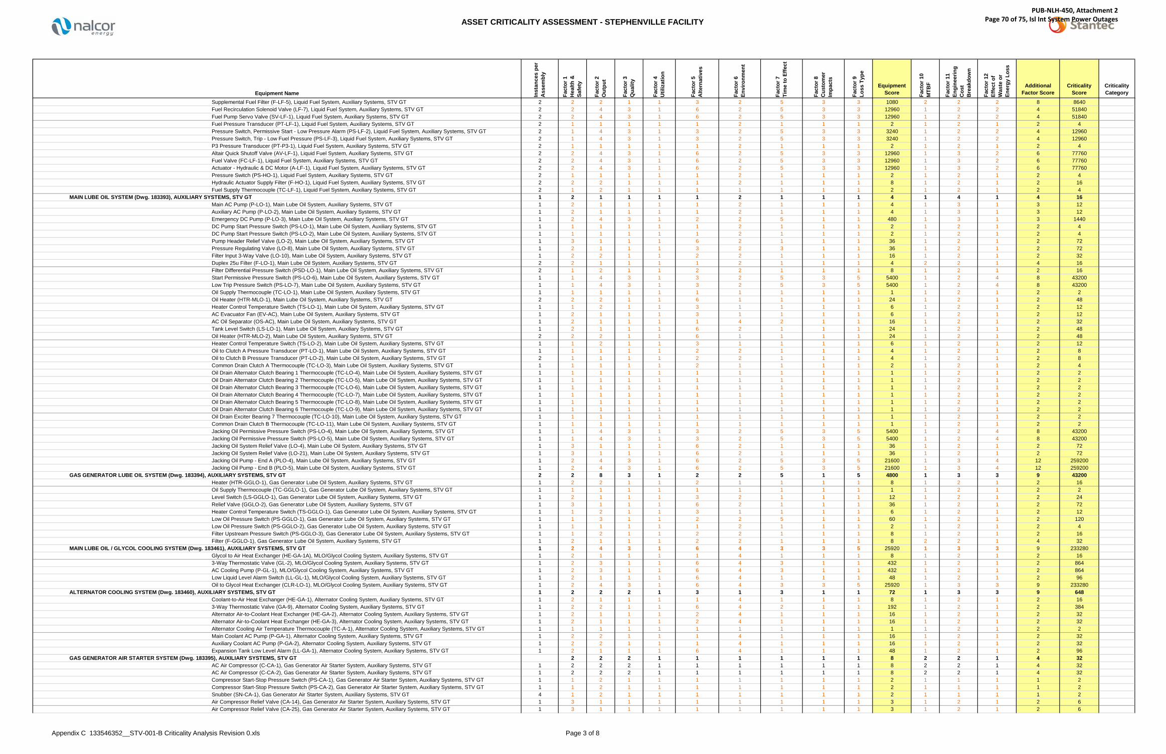
ASSET CRITICALITY ASSESSMENT - STEPHENVILLE FACILITY
Appendix C 133546352__STV-001-B Criticality Analysis Revision 0.xls Page 3 of 8
Inst
ance
s pe
r A
ssem
bly
Fact
or 1
Hea
lth &
Sa
fety
Fact
or 2
Out
put
Fact
or 3
Qua
lity
Fact
or 4
Util
izat
ion
Fact
or 5
A
ltern
ativ
es
Fact
or 6
Envi
ronm
ent
Fact
or 7
Tim
e to
Effe
ct
Fact
or 8
Cus
tom
er
Impa
cts
Fact
or 9
Loss
Typ
e
EquipmentScore Fa
ctor
10
MTB
F
Fact
or 1
1En
gine
erin
g C
ost
Bre
akdo
wn
Fact
or 1
2Ef
fect
of
Was
te o
r En
ergy
Los
s
AdditionalFactor Score
CriticalityScore
CriticalityCategoryEquipment Name
Supplemental Fuel Filter (F-LF-5), Liquid Fuel System, Auxiliary Systems, STV GT 2 2 2 1 1 3 2 5 3 3 1080 2 2 2 8 8640Fuel Recirculation Solenoid Valve (LF-7), Liquid Fuel System, Auxiliary Systems, STV GT 2 2 4 3 1 6 2 5 3 3 12960 1 2 2 4 51840Fuel Pump Servo Valve (SV-LF-1), Liquid Fuel System, Auxiliary Systems, STV GT 2 2 4 3 1 6 2 5 3 3 12960 1 2 2 4 51840Fuel Pressure Transducer (PT-LF-1), Liquid Fuel System, Auxiliary Systems, STV GT 2 1 1 1 1 1 2 1 1 1 2 1 2 1 2 4Pressure Switch, Permissive Start - Low Pressure Alarm (PS-LF-2), Liquid Fuel System, Auxiliary Systems, STV GT 2 1 4 3 1 3 2 5 3 3 3240 1 2 2 4 12960Pressure Switch, Trip - Low Fuel Pressure (PS-LF-3), Liquid Fuel System, Auxiliary Systems, STV GT 2 1 4 3 1 3 2 5 3 3 3240 1 2 2 4 12960P3 Pressure Transducer (PT-P3-1), Liquid Fuel System, Auxiliary Systems, STV GT 2 1 1 1 1 1 2 1 1 1 2 1 2 1 2 4Altair Quick Shutoff Valve (AV-LF-1), Liquid Fuel System, Auxiliary Systems, STV GT 2 2 4 3 1 6 2 5 3 3 12960 1 3 2 6 77760Fuel Valve (FC-LF-1), Liquid Fuel System, Auxiliary Systems, STV GT 2 2 4 3 1 6 2 5 3 3 12960 1 3 2 6 77760Actuator - Hydraulic & DC Motor (A-LF-1), Liquid Fuel System, Auxiliary Systems, STV GT 2 2 4 3 1 6 2 5 3 3 12960 1 3 2 6 77760Pressure Switch (PS-HO-1), Liquid Fuel System, Auxiliary Systems, STV GT 2 1 1 1 1 1 2 1 1 1 2 1 2 1 2 4Hydraulic Actuator Supply Filter (F-HO-1), Liquid Fuel System, Auxiliary Systems, STV GT 2 2 2 1 1 1 2 1 1 1 8 1 2 1 2 16Fuel Supply Thermocouple (TC-LF-1), Liquid Fuel System, Auxiliary Systems, STV GT 2 1 2 1 1 1 1 1 1 1 2 1 2 1 2 4
MAIN LUBE OIL SYSTEM (Dwg. 183393), AUXILIARY SYSTEMS, STV GT 1 2 1 1 1 1 2 1 1 1 4 1 4 1 4 16Main AC Pump (P-LO-1), Main Lube Oil System, Auxiliary Systems, STV GT 1 2 1 1 1 1 2 1 1 1 4 1 3 1 3 12Auxiliary AC Pump (P-LO-2), Main Lube Oil System, Auxiliary Systems, STV GT 1 2 1 1 1 1 2 1 1 1 4 1 3 1 3 12Emergency DC Pump (P-LO-3), Main Lube Oil System, Auxiliary Systems, STV GT 1 2 4 3 1 2 2 5 1 1 480 1 3 1 3 1440DC Pump Start Pressure Switch (PS-LO-1), Main Lube Oil System, Auxiliary Systems, STV GT 1 1 1 1 1 1 2 1 1 1 2 1 2 1 2 4DC Pump Start Pressure Switch (PS-LO-2), Main Lube Oil System, Auxiliary Systems, STV GT 1 1 1 1 1 1 2 1 1 1 2 1 2 1 2 4Pump Header Relief Valve (LO-2), Main Lube Oil System, Auxiliary Systems, STV GT 1 3 1 1 1 6 2 1 1 1 36 1 2 1 2 72Pressure Regulating Valve (LO-8), Main Lube Oil System, Auxiliary Systems, STV GT 1 2 1 1 1 3 2 3 1 1 36 1 2 1 2 72Filter Input 3-Way Valve (LO-10), Main Lube Oil System, Auxiliary Systems, STV GT 1 2 2 1 1 2 2 1 1 1 16 1 2 1 2 32Duplex 25u Filter (F-LO-1), Main Lube Oil System, Auxiliary Systems, STV GT 2 2 1 1 1 1 2 1 1 1 4 2 2 1 4 16Filter Differential Pressure Switch (PSD-LO-1), Main Lube Oil System, Auxiliary Systems, STV GT 2 1 2 1 1 2 2 1 1 1 8 1 2 1 2 16Start Permissive Pressure Switch (PS-LO-6), Main Lube Oil System, Auxiliary Systems, STV GT 1 1 4 3 1 3 2 5 3 5 5400 1 2 4 8 43200Low Trip Pressure Switch (PS-LO-7), Main Lube Oil System, Auxiliary Systems, STV GT 1 1 4 3 1 3 2 5 3 5 5400 1 2 4 8 43200Oil Supply Thermocouple (TC-LO-1), Main Lube Oil System, Auxiliary Systems, STV GT 1 1 1 1 1 1 1 1 1 1 1 1 2 1 2 2Oil Heater (HTR-MLO-1), Main Lube Oil System, Auxiliary Systems, STV GT 2 2 2 1 1 6 1 1 1 1 24 1 2 1 2 48Heater Control Temperature Switch (TS-LO-1), Main Lube Oil System, Auxiliary Systems, STV GT 1 1 2 1 1 3 1 1 1 1 6 1 2 1 2 12AC Evacuator Fan (EV-AC), Main Lube Oil System, Auxiliary Systems, STV GT 1 2 1 1 1 3 1 1 1 1 6 1 2 1 2 12AC Oil Separator (OS-AC), Main Lube Oil System, Auxiliary Systems, STV GT 1 2 1 1 1 1 4 2 1 1 16 1 2 1 2 32Tank Level Switch (LS-LO-1), Main Lube Oil System, Auxiliary Systems, STV GT 1 2 1 1 1 6 2 1 1 1 24 1 2 1 2 48Oil Heater (HTR-MLO-2), Main Lube Oil System, Auxiliary Systems, STV GT 2 2 2 1 1 6 1 1 1 1 24 1 2 1 2 48Heater Control Temperature Switch (TS-LO-2), Main Lube Oil System, Auxiliary Systems, STV GT 1 1 2 1 1 3 1 1 1 1 6 1 2 1 2 12Oil to Clutch A Pressure Transducer (PT-LO-1), Main Lube Oil System, Auxiliary Systems, STV GT 1 1 1 1 1 2 2 1 1 1 4 1 2 1 2 8Oil to Clutch B Pressure Transducer (PT-LO-2), Main Lube Oil System, Auxiliary Systems, STV GT 2 1 1 1 1 2 2 1 1 1 4 1 2 1 2 8Common Drain Clutch A Thermocouple (TC-LO-3), Main Lube Oil System, Auxiliary Systems, STV GT 1 1 1 1 1 2 1 1 1 1 2 1 2 1 2 4Oil Drain Alternator Clutch Bearing 1 Thermocouple (TC-LO-4), Main Lube Oil System, Auxiliary Systems, STV GT 1 1 1 1 1 1 1 1 1 1 1 1 2 1 2 2Oil Drain Alternator Clutch Bearing 2 Thermocouple (TC-LO-5), Main Lube Oil System, Auxiliary Systems, STV GT 1 1 1 1 1 1 1 1 1 1 1 1 2 1 2 2Oil Drain Alternator Clutch Bearing 3 Thermocouple (TC-LO-6), Main Lube Oil System, Auxiliary Systems, STV GT 1 1 1 1 1 1 1 1 1 1 1 1 2 1 2 2Oil Drain Alternator Clutch Bearing 4 Thermocouple (TC-LO-7), Main Lube Oil System, Auxiliary Systems, STV GT 1 1 1 1 1 1 1 1 1 1 1 1 2 1 2 2Oil Drain Alternator Clutch Bearing 5 Thermocouple (TC-LO-8), Main Lube Oil System, Auxiliary Systems, STV GT 1 1 1 1 1 1 1 1 1 1 1 1 2 1 2 2Oil Drain Alternator Clutch Bearing 6 Thermocouple (TC-LO-9), Main Lube Oil System, Auxiliary Systems, STV GT 1 1 1 1 1 1 1 1 1 1 1 1 2 1 2 2Oil Drain Exciter Bearing 7 Thermocouple (TC-LO-10), Main Lube Oil System, Auxiliary Systems, STV GT 1 1 1 1 1 1 1 1 1 1 1 1 2 1 2 2Common Drain Clutch B Thermocouple (TC-LO-11), Main Lube Oil System, Auxiliary Systems, STV GT 1 1 1 1 1 1 1 1 1 1 1 1 2 1 2 2Jacking Oil Permissive Pressure Switch (PS-LO-4), Main Lube Oil System, Auxiliary Systems, STV GT 1 1 4 3 1 3 2 5 3 5 5400 1 2 4 8 43200Jacking Oil Permissive Pressure Switch (PS-LO-5), Main Lube Oil System, Auxiliary Systems, STV GT 1 1 4 3 1 3 2 5 3 5 5400 1 2 4 8 43200Jacking Oil System Relief Valve (LO-4), Main Lube Oil System, Auxiliary Systems, STV GT 1 3 1 1 1 6 2 1 1 1 36 1 2 1 2 72Jacking Oil System Relief Valve (LO-21), Main Lube Oil System, Auxiliary Systems, STV GT 1 3 1 1 1 6 2 1 1 1 36 1 2 1 2 72Jacking Oil Pump - End A (PLO-4), Main Lube Oil System, Auxiliary Systems, STV GT 1 2 4 3 1 6 2 5 3 5 21600 1 3 4 12 259200Jacking Oil Pump - End B (PLO-5), Main Lube Oil System, Auxiliary Systems, STV GT 1 2 4 3 1 6 2 5 3 5 21600 1 3 4 12 259200
GAS GENERATOR LUBE OIL SYSTEM (Dwg. 183394), AUXILIARY SYSTEMS, STV GT 2 2 8 3 1 2 2 5 1 5 4800 1 3 3 9 43200Heater (HTR-GGLO-1), Gas Generator Lube Oil System, Auxiliary Systems, STV GT 1 2 2 1 1 2 1 1 1 1 8 1 2 1 2 16Oil Supply Thermocouple (TC-GGLO-1), Gas Generator Lube Oil System, Auxiliary Systems, STV GT 1 1 1 1 1 1 1 1 1 1 1 1 2 1 2 2Level Switch (LS-GGLO-1), Gas Generator Lube Oil System, Auxiliary Systems, STV GT 1 2 1 1 1 3 2 1 1 1 12 1 2 1 2 24Relief Valve (GGLO-2), Gas Generator Lube Oil System, Auxiliary Systems, STV GT 1 3 1 1 1 6 2 1 1 1 36 1 2 1 2 72Heater Control Temperature Switch (TS-GGLO-1), Gas Generator Lube Oil System, Auxiliary Systems, STV GT 1 1 2 1 1 3 1 1 1 1 6 1 2 1 2 12Low Oil Pressure Switch (PS-GGLO-1), Gas Generator Lube Oil System, Auxiliary Systems, STV GT 1 1 3 1 1 2 2 5 1 1 60 1 2 1 2 120Low Oil Pressure Switch (PS-GGLO-2), Gas Generator Lube Oil System, Auxiliary Systems, STV GT 1 1 1 1 1 1 2 1 1 1 2 1 2 1 2 4Filter Upstream Pressure Switch (PS-GGLO-3), Gas Generator Lube Oil System, Auxiliary Systems, STV GT 1 1 2 1 1 2 2 1 1 1 8 1 2 1 2 16Filter (F-GGLO-1), Gas Generator Lube Oil System, Auxiliary Systems, STV GT 1 2 1 1 1 2 2 1 1 1 8 2 2 1 4 32
MAIN LUBE OIL / GLYCOL COOLING SYSTEM (Dwg. 183461), AUXILIARY SYSTEMS, STV GT 1 2 4 3 1 6 4 3 3 5 25920 1 3 3 9 233280Glycol to Air Heat Exchanger (HE-GA-1A), MLO/Glycol Cooling System, Auxiliary Systems, STV GT 1 2 1 1 1 1 4 1 1 1 8 1 2 1 2 163-Way Thermostatic Valve (GL-2), MLO/Glycol Cooling System, Auxiliary Systems, STV GT 1 2 3 1 1 6 4 3 1 1 432 1 2 1 2 864AC Cooling Pump (P-GL-1), MLO/Glycol Cooling System, Auxiliary Systems, STV GT 1 2 3 1 1 6 4 3 1 1 432 1 2 1 2 864Low Liquid Level Alarm Switch (LL-GL-1), MLO/Glycol Cooling System, Auxiliary Systems, STV GT 1 2 1 1 1 6 4 1 1 1 48 1 2 1 2 96Oil to Glycol Heat Exchanger (CLR-LO-1), MLO/Glycol Cooling System, Auxiliary Systems, STV GT 1 2 4 3 1 6 4 3 3 5 25920 1 3 3 9 233280
ALTERNATOR COOLING SYSTEM (Dwg. 183460), AUXILIARY SYSTEMS, STV GT 1 2 2 2 1 3 1 3 1 1 72 1 3 3 9 648Coolant-to-Air Heat Exchanger (HE-GA-1), Alternator Cooling System, Auxiliary Systems, STV GT 1 2 1 1 1 1 4 1 1 1 8 1 2 1 2 163-Way Thermostatic Valve (GA-9), Alternator Cooling System, Auxiliary Systems, STV GT 1 2 2 1 1 6 4 2 1 1 192 1 2 1 2 384Alternator Air-to-Coolant Heat Exchanger (HE-GA-2), Alternator Cooling System, Auxiliary Systems, STV GT 1 2 1 1 1 2 4 1 1 1 16 1 2 1 2 32Alternator Air-to-Coolant Heat Exchanger (HE-GA-3), Alternator Cooling System, Auxiliary Systems, STV GT 1 2 1 1 1 2 4 1 1 1 16 1 2 1 2 32Alternator Cooling Air Temperature Thermocouple (TC-A-1), Alternator Cooling System, Auxiliary Systems, STV GT 1 1 1 1 1 1 1 1 1 1 1 1 2 1 2 2Main Coolant AC Pump (P-GA-1), Alternator Cooling System, Auxiliary Systems, STV GT 1 2 2 1 1 1 4 1 1 1 16 1 2 1 2 32Auxiliary Coolant AC Pump (P-GA-2), Alternator Cooling System, Auxiliary Systems, STV GT 1 2 2 1 1 1 4 1 1 1 16 1 2 1 2 32Expansion Tank Low Level Alarm (LL-GA-1), Alternator Cooling System, Auxiliary Systems, STV GT 1 2 1 1 1 6 4 1 1 1 48 1 2 1 2 96
GAS GENERATOR AIR STARTER SYSTEM (Dwg. 183395), AUXILIARY SYSTEMS, STV GT 2 2 2 1 1 1 1 1 1 8 2 2 1 4 32AC Air Compressor (C-CA-1), Gas Generator Air Starter System, Auxiliary Systems, STV GT 1 2 2 2 1 1 1 1 1 1 8 2 2 1 4 32AC Air Compressor (C-CA-2), Gas Generator Air Starter System, Auxiliary Systems, STV GT 1 2 2 2 1 1 1 1 1 1 8 2 2 1 4 32Compressor Start-Stop Pressure Switch (PS-CA-1), Gas Generator Air Starter System, Auxiliary Systems, STV GT 1 1 2 1 1 1 1 1 1 1 2 1 1 1 1 2Compressor Start-Stop Pressure Switch (PS-CA-2), Gas Generator Air Starter System, Auxiliary Systems, STV GT 1 1 2 1 1 1 1 1 1 1 2 1 1 1 1 2Snubber (SN-CA-1), Gas Generator Air Starter System, Auxiliary Systems, STV GT 4 1 2 1 1 1 1 1 1 1 2 1 1 1 1 2Air Compressor Relief Valve (CA-14), Gas Generator Air Starter System, Auxiliary Systems, STV GT 1 3 1 1 1 1 1 1 1 1 3 1 2 1 2 6Air Compressor Relief Valve (CA-25), Gas Generator Air Starter System, Auxiliary Systems, STV GT 1 3 1 1 1 1 1 1 1 1 3 1 2 1 2 6
PUB-NLH-450, Attachment 2 Page 70 of 75, Isl Int System Power Outages

ASSET CRITICALITY ASSESSMENT - STEPHENVILLE FACILITY
Appendix C 133546352__STV-001-B Criticality Analysis Revision 0.xls Page 4 of 8
Inst
ance
s pe
r A
ssem
bly
Fact
or 1
Hea
lth &
Sa
fety
Fact
or 2
Out
put
Fact
or 3
Qua
lity
Fact
or 4
Util
izat
ion
Fact
or 5
A
ltern
ativ
es
Fact
or 6
Envi
ronm
ent
Fact
or 7
Tim
e to
Effe
ct
Fact
or 8
Cus
tom
er
Impa
cts
Fact
or 9
Loss
Typ
e
EquipmentScore Fa
ctor
10
MTB
F
Fact
or 1
1En
gine
erin
g C
ost
Bre
akdo
wn
Fact
or 1
2Ef
fect
of
Was
te o
r En
ergy
Los
s
AdditionalFactor Score
CriticalityScore
CriticalityCategoryEquipment Name
Air Receiver Relief Valve (CA-13), Gas Generator Air Starter System, Auxiliary Systems, STV GT 1 3 1 1 1 1 1 1 1 1 3 1 2 1 2 6Air Receiver Relief Valve (CA-26), Gas Generator Air Starter System, Auxiliary Systems, STV GT 1 3 1 1 1 1 1 1 1 1 3 1 2 1 2 6Heating Cable (HTR-CA-1), Gas Generator Air Starter System, Auxiliary Systems, STV GT 1 2 2 1 1 2 2 1 1 1 16 1 1 1 1 16Heating Cable (HTR-CA-2), Gas Generator Air Starter System, Auxiliary Systems, STV GT 1 2 2 1 1 2 2 1 1 1 16 1 1 1 1 16Automatic Condensate Drain Trap (DT-CA-1), Gas Generator Air Starter System, Auxiliary Systems, STV GT 1 1 2 1 1 2 1 1 1 1 4 1 1 1 1 4Automatic Condensate Drain Trap (DT-CA-2), Gas Generator Air Starter System, Auxiliary Systems, STV GT 1 1 2 1 1 2 1 1 1 1 4 1 1 1 1 4Gas Generator Permissive Start Pressure Switch (PS-CA-4), Gas Generator Air Starter System, Auxiliary Systems, STV GT 1 1 3 3 1 3 1 5 1 3 405 1 2 2 4 1620Gas Generator Permissive Start Pressure Switch (PS-CA-5), Gas Generator Air Starter System, Auxiliary Systems, STV GT 1 1 3 3 1 3 1 5 1 3 405 1 2 2 4 1620Starter Control Valve (CA-17), Gas Generator Air Starter System, Auxiliary Systems, STV GT 2 1 3 3 1 6 1 5 1 3 810 1 2 2 4 3240Starter Overpressure Pressure Switch (PS-CA-3), Gas Generator Air Starter System, Auxiliary Systems, STV GT 2 1 3 3 1 3 1 5 1 3 405 1 2 2 4 1620Relief Valve (CA-20), Gas Generator Air Starter System, Auxiliary Systems, STV GT 2 3 1 1 1 6 1 1 1 1 18 1 2 1 2 36Control Air Dryer (F-CA-1), Gas Generator Air Starter System, Auxiliary Systems, STV GT 2 1 1 1 1 1 1 1 1 1 1 1 2 1 2 2NO Solenoid Valve (SV-CA-1), Gas Generator Air Starter System, Auxiliary Systems, STV GT 2 1 3 3 1 6 1 5 1 3 810 1 2 2 4 3240NC Solenoid Valve (SV-CA-2), Gas Generator Air Starter System, Auxiliary Systems, STV GT 2 1 3 3 1 6 1 5 1 3 810 1 2 2 4 3240NC Solenoid Valve (SV-CA-3), Gas Generator Air Starter System, Auxiliary Systems, STV GT 2 1 1 1 1 2 1 1 1 1 2 1 2 1 2 4Air Regulator (CA-17-A), Gas Generator Air Starter System, Auxiliary Systems, STV GT 2 1 1 1 1 2 1 1 1 1 2 1 2 1 2 4Air Regulator (CA-17-B), Gas Generator Air Starter System, Auxiliary Systems, STV GT 2 1 1 1 1 2 1 1 1 1 2 1 2 1 2 4
FIRE PROTECTION SYSTEM, AUXILIARY SYSTEMS, STV GT 0 0 0Control Room Inergen System, Fire Protection System, Auxiliary Systems, STV GT 1 1 1 1 2 1 1 1 1 2 1 2 1 2 4
Compressed Gas Tank, Control Room Inergen System, Fire Protection System, Auxiliary Systems, STV GT 0 0 0Power Generation Module Inergen System, Fire Protection System, Auxiliary Systems, STV GT 0 0 0
Compressed Gas Tank, Power Generation Module Inergen System, Fire Protection System, Auxiliary Systems, STV GT 0 0 0Switchgear Room Inergen System, Fire Protection System, Auxiliary Systems, STV GT 0 0 0
Compressed Gas Tank, Switchgear Module Inergen System, Fire Protection System, Auxiliary Systems, STV GT 0 0 0
BUILDING AND PROPERTY, STV GTMaintenance Building, STV GT 0 0 0Switchgear Module, STV GT 0 0 0Fuel Offloading / Forwarding Module, STV GT 0 0 0Fence, STV GT 0 0 0Water System, STV GT 0 0 0Waste Disposal System, STV GT 0 0 0Fall Protection System, STV GT 0 0 0End A Overhead Crane, STV GT 0 0 0End B Overhead Crane, STV GT 0 0 0Sump and Drain Lines, STV GT 0 0 0Portable Washrooms, STV GT 0 0 0
PUB-NLH-450, Attachment 2 Page 71 of 75, Isl Int System Power Outages

ASSET CRITICALITY ASSESSMENT - STEPHENVILLE FACILITYCritical Components
Appendix C 133546352__STV-001-B Criticality Analysis Revision 0.xls
Asset Number Asset DescriptionOutput
Ranking
Health & Safety
RankingEnviroment
Ranking
Stocked Spare Item
BOM Item
Ability to
Detect (L/M/H)
Factor 8MTBF
CI Item
Lube Item
Std Job Item
PdM Itemlater
PM Itemlater
88096 JET ENGINE A 1555200 6 2 Liquid Fuel Burner - Complete (BDC.3026), Gas Generator, End "A", Prime Mover Systems, STV GT 488096 JET ENGINE A 1555200 6 2 Combustion Chamber, Gas Generator, End "A", Prime Mover Systems, STV GT 488096 JET ENGINE A 1555200 6 2 Upper Fuel Pump Assembly, Gas Generator, End "A", Prime Mover Systems, STV GT 488096 JET ENGINE A 1555200 6 2 Lower Fuel Pump Assembly, Gas Generator, End "A", Prime Mover Systems, STV GT 488096 JET ENGINE A 1555200 6 2 Outer Fuel Pump Drive Assembly (BDA.7591), Gas Generator, End "A", Prime Mover Systems, STV GT 488096 JET ENGINE A 1555200 6 2 Oil Pump - Complete, Gas Generator, End "A", Prime Mover Systems, STV GT 488096 JET ENGINE A 1555200 6 2 Outer Oil Pump Drive Assembly (47-1-1-006409), Gas Generator, End "A", Prime Mover Systems, STV GT 488096 JET ENGINE A 1555200 6 2 Scavenge Pump Assembly (47-1-1-006418), Gas Generator, End "A", Prime Mover Systems, STV GT 488096 JET ENGINE A 1555200 6 2 Outer Starter Drive Assembly (BDA.1153), Gas Generator, End "A", Prime Mover Systems, STV GT 46614 JET ENGINE B 1555200 6 2 Liquid Fuel Burner - Complete (BDC.3026), Gas Generator, End "B", Prime Mover Systems, STV GT 46614 JET ENGINE B 1555200 6 2 Combustion Chamber, Gas Generator, End "B", Prime Mover Systems, STV GT 46614 JET ENGINE B 1555200 6 2 Upper Fuel Pump Assembly, Gas Generator, End "B", Prime Mover Systems, STV GT 46614 JET ENGINE B 1555200 6 2 Lower Fuel Pump Assembly, Gas Generator, End "B", Prime Mover Systems, STV GT 46614 JET ENGINE B 1555200 6 2 Outer Fuel Pump Drive Assembly (BDA.7591), Gas Generator, End "B", Prime Mover Systems, STV GT 46614 JET ENGINE B 1555200 6 2 Oil Pump - Complete, Gas Generator, End "B", Prime Mover Systems, STV GT 46614 JET ENGINE B 1555200 6 2 Outer Oil Pump Drive Assembly (47-1-1-006409), Gas Generator, End "B", Prime Mover Systems, STV GT 46614 JET ENGINE B 1555200 6 2 Scavenge Pump Assembly (47-1-1-006418), Gas Generator, End "B", Prime Mover Systems, STV GT 46614 JET ENGINE B 1555200 6 2 Outer Starter Drive Assembly (BDA.1153), Gas Generator, End "B", Prime Mover Systems, STV GT 488096 JET ENGINE A 777600 6 1 High Energy Ignition Unit, Gas Generator, End "A", Prime Mover Systems, STV GT 46614 JET ENGINE B 777600 6 1 High Energy Ignition Unit, Gas Generator, End "B", Prime Mover Systems, STV GT 4
88143 GENERATOR 518400 1 4 Grounding Transformer, 63MVA 50MW Generator, Power Generation Systems, STV GT 188143 GENERATOR 518400 1 4 Potential Transformers, 63MVA 50MW Generator, Power Generation Systems, STV GT 188143 GENERATOR 518400 1 4 Current Transformers, 63MVA 50MW Generator, Power Generation Systems, STV GT 188143 GENERATOR 432000 1 2 Rotor, 63MVA 50MW Generator, Power Generation Systems, STV GT 188143 GENERATOR 432000 1 2 Stator, 63MVA 50MW Generator, Power Generation Systems, STV GT 188227 FUEL FORWARDING 388800 5 6 Fire Fuel Shutoff Valve (LF-8), Liquid Fuel System, Auxiliary Systems, STV GT 188096 JET ENGINE A 388800 6 1 Anti-Icing Hot Air Valve - Complete (810-501-0747), Gas Generator, End "A", Prime Mover Systems, STV GT 56614 JET ENGINE B 388800 6 1 Anti-Icing Hot Air Valve - Complete (810-501-0747), Gas Generator, End "B", Prime Mover Systems, STV GT 588149 EXCITATION SYSTEM 345600 1 2 Exciter Bearing, 63MVA 50MW Generator, Power Generation Systems, STV GT 188143 GENERATOR 345600 1 2 Rotor Bearing, 63MVA 50MW Generator, Power Generation Systems, STV GT 188106 POWER TURBINE A 311040 6 2 Bearing (181413 or 181332), Power Turbine Model CT2, End "A", Prime Mover Systems, STV GT 188106 POWER TURBINE A 311040 6 2 Bearing (494047), Power Turbine Model CT2, End "A", Prime Mover Systems, STV GT 188106 POWER TURBINE A 311040 6 2 Bearing (494056), Power Turbine Model CT2, End "A", Prime Mover Systems, STV GT 188113 POWER TURBINE B 311040 6 2 Bearing (181413 or 181332), Power Turbine Model CT2, End "B", Prime Mover Systems, STV GT 188113 POWER TURBINE B 311040 6 2 Bearing (494047), Power Turbine Model CT2, End "B", Prime Mover Systems, STV GT 188113 POWER TURBINE B 311040 6 2 Bearing (494056), Power Turbine Model CT2, End "B", Prime Mover Systems, STV GT 188149 EXCITATION SYSTEM 259200 2 1 Exciter, 63MVA 50MW Generator, Power Generation Systems, STV GT 188258 LUBE OIL SYSTEM 259200 2 2 Jacking Oil Pump - End A (PLO-4), Main Lube Oil System, Auxiliary Systems, STV GT 188258 LUBE OIL SYSTEM 259200 2 2 Jacking Oil Pump - End B (PLO-5), Main Lube Oil System, Auxiliary Systems, STV GT 188096 JET ENGINE A 259200 6 1 LP Compressor Magnetic Pickup, Gas Generator, End "A", Prime Mover Systems, STV GT 488096 JET ENGINE A 259200 6 1 HP Compressor Magnetic Pickup, Gas Generator, End "A", Prime Mover Systems, STV GT 488096 JET ENGINE A 259200 6 1 Vibration Transducer, Gas Generator, End "A", Prime Mover Systems, STV GT 46614 JET ENGINE B 259200 6 1 LP Compressor Magnetic Pickup, Gas Generator, End "B", Prime Mover Systems, STV GT 46614 JET ENGINE B 259200 6 1 HP Compressor Magnetic Pickup, Gas Generator, End "B", Prime Mover Systems, STV GT 46614 JET ENGINE B 259200 6 1 Vibration Transducer, Gas Generator, End "B", Prime Mover Systems, STV GT 488284 GLYCOL 233280 2 4 Oil to Glycol Heat Exchanger (CLR-LO-1), MLO/Glycol Cooling System, Auxiliary Systems, STV GT 188096 JET ENGINE A 184320 6 2 Fuel Filter, Gas Generator, Prime Mover Systems, STV GT 488096 JET ENGINE A 184320 6 2 Oil Filter Unit - Complete (B.108506), Gas Generator, End "A", Prime Mover Systems, STV GT 46614 JET ENGINE B 184320 6 2 Fuel Filter, Gas Generator, Prime Mover Systems, STV GT 46614 JET ENGINE B 184320 6 2 Oil Filter Unit - Complete (B.108506), Gas Generator, End "B", Prime Mover Systems, STV GT 488106 POWER TURBINE A 122880 4 2 Filter (494064), Power Turbine Model CT2, End "A", Prime Mover Systems, STV GT 488113 POWER TURBINE B 122880 4 2 Filter (494064), Power Turbine Model CT2, End "B", Prime Mover Systems, STV GT 488128 CLUTCH A 86400 2 2 Proximity Switch, Clutch, End "A", Prime Mover Systems, STV GT 588133 CLUTCH B 86400 2 2 Proximity Switch, Clutch, End "B", Prime Mover Systems, STV GT 588227 FUEL FORWARDING 77760 2 2 Supplemental Fuel AC Pump (P&MLF-5), Liquid Fuel System, Auxiliary Systems, STV GT 188227 FUEL FORWARDING 77760 2 2 Altair Quick Shutoff Valve (AV-LF-1), Liquid Fuel System, Auxiliary Systems, STV GT 188227 FUEL FORWARDING 77760 2 2 Fuel Valve (FC-LF-1), Liquid Fuel System, Auxiliary Systems, STV GT 188227 FUEL FORWARDING 77760 2 2 Actuator - Hydraulic & DC Motor (A-LF-1), Liquid Fuel System, Auxiliary Systems, STV GT 188227 FUEL FORWARDING 51840 2 2 Fuel Regulator (LF-4), Liquid Fuel System, Auxiliary Systems, STV GT 188227 FUEL FORWARDING 51840 2 2 Fuel Recirculation Solenoid Valve (LF-7), Liquid Fuel System, Auxiliary Systems, STV GT 188227 FUEL FORWARDING 51840 2 2 Fuel Pump Servo Valve (SV-LF-1), Liquid Fuel System, Auxiliary Systems, STV GT 188258 LUBE OIL SYSTEM 43200 1 2 Start Permissive Pressure Switch (PS-LO-6), Main Lube Oil System, Auxiliary Systems, STV GT 188258 LUBE OIL SYSTEM 43200 1 2 Low Trip Pressure Switch (PS-LO-7), Main Lube Oil System, Auxiliary Systems, STV GT 188258 LUBE OIL SYSTEM 43200 1 2 Jacking Oil Permissive Pressure Switch (PS-LO-4), Main Lube Oil System, Auxiliary Systems, STV GT 188258 LUBE OIL SYSTEM 43200 1 2 Jacking Oil Permissive Pressure Switch (PS-LO-5), Main Lube Oil System, Auxiliary Systems, STV GT 188227 FUEL FORWARDING 43200 2 2 Forwarding DC Emergency Pump No 2, Liquid Fuel System, Auxiliary Systems, STV GT 188128 CLUTCH A 25920 2 2 Primary Ratchet Ring, Clutch, End "A", Prime Mover Systems, STV GT 1
Critical Components
PUB-NLH-450, Attachment 2 Page 72 of 75, Isl Int System Power Outages

ASSET CRITICALITY ASSESSMENT - STEPHENVILLE FACILITYCritical Components
Appendix C 133546352__STV-001-B Criticality Analysis Revision 0.xls
Asset Number Asset DescriptionOutput
Ranking
Health & Safety
RankingEnviroment
Ranking
Stocked Spare Item
BOM Item
Ability to
Detect (L/M/H)
Factor 8MTBF
CI Item
Lube Item
Std Job Item
PdM Itemlater
PM ItemlaterCritical Components
88128 CLUTCH A 25920 2 2 Secondary Ratchet Ring, Clutch, End "A", Prime Mover Systems, STV GT 188133 CLUTCH B 25920 2 2 Primary Ratchet Ring, Clutch, End "B", Prime Mover Systems, STV GT 188133 CLUTCH B 25920 2 2 Secondary Ratchet Ring, Clutch, End "B", Prime Mover Systems, STV GT 188106 POWER TURBINE A 25920 4 1 Valve (181536), Power Turbine Model CT2, End "A", Prime Mover Systems, STV GT 188113 POWER TURBINE B 25920 4 1 Valve (181536), Power Turbine Model CT2, End "B", Prime Mover Systems, STV GT 188128 CLUTCH A 17280 2 2 Primary Pawl, Clutch, End "A", Prime Mover Systems, STV GT 188128 CLUTCH A 17280 2 2 Secondary Pawl, Clutch, End "A", Prime Mover Systems, STV GT 188128 CLUTCH A 17280 2 2 Primary Pawl Spring, Clutch, End "A", Prime Mover Systems, STV GT 188133 CLUTCH B 17280 2 2 Primary Pawl, Clutch, End "B", Prime Mover Systems, STV GT 188133 CLUTCH B 17280 2 2 Secondary Pawl, Clutch, End "B", Prime Mover Systems, STV GT 188133 CLUTCH B 17280 2 2 Primary Pawl Spring, Clutch, End "B", Prime Mover Systems, STV GT 188227 FUEL FORWARDING 12960 1 2 Pressure Switch, Permissive Start - Low Pressure Alarm (PS-LF-2), Liquid Fuel System, Auxiliary Systems, STV GT 188227 FUEL FORWARDING 12960 1 2 Pressure Switch, Trip - Low Fuel Pressure (PS-LF-3), Liquid Fuel System, Auxiliary Systems, STV GT 188117 EXHAUST A 8640 2 1 Double-Acting Pneumatic Cylinder, Snow Door Assembly, Exhaust, End "A", Prime Mover Systems, STV GT 188117 EXHAUST A 8640 2 1 Limit Switch, Snow Door Assembly, Exhaust, End "A", Prime Mover Systems, STV GT 188122 EXHAUST B 8640 2 1 Double-Acting Pneumatic Cylinder, Snow Door Assembly, Exhaust, End "B", Prime Mover Systems, STV GT 188122 EXHAUST B 8640 2 1 Limit Switch, Snow Door Assembly, Exhaust, End "B", Prime Mover Systems, STV GT 188227 FUEL FORWARDING 8640 2 2 Supplemental Fuel Filter (F-LF-5), Liquid Fuel System, Auxiliary Systems, STV GT 288237 COMPRESSED AIR SYSTEM,SVLGT 3240 1 1 Starter Control Valve (CA-17), Gas Generator Air Starter System, Auxiliary Systems, STV GT 188237 COMPRESSED AIR SYSTEM,SVLGT 3240 1 1 NO Solenoid Valve (SV-CA-1), Gas Generator Air Starter System, Auxiliary Systems, STV GT 188237 COMPRESSED AIR SYSTEM,SVLGT 3240 1 1 NC Solenoid Valve (SV-CA-2), Gas Generator Air Starter System, Auxiliary Systems, STV GT 1
298945 250 VDC BATT CHG, SVL 1728 2 2 Battery, 250 VDC Battery Bank, D.C. Electrical System, Power Generation Systems, STV GT 188237 COMPRESSED AIR SYSTEM,SVLGT 1620 1 1 Gas Generator Permissive Start Pressure Switch (PS-CA-4), Gas Generator Air Starter System, Auxiliary Systems, STV GT 188237 COMPRESSED AIR SYSTEM,SVLGT 1620 1 1 Gas Generator Permissive Start Pressure Switch (PS-CA-5), Gas Generator Air Starter System, Auxiliary Systems, STV GT 188237 COMPRESSED AIR SYSTEM,SVLGT 1620 1 1 Starter Overpressure Pressure Switch (PS-CA-3), Gas Generator Air Starter System, Auxiliary Systems, STV GT 188258 LUBE OIL SYSTEM 1440 2 2 Emergency DC Pump (P-LO-3), Main Lube Oil System, Auxiliary Systems, STV GT 188284 GLYCOL 864 2 4 3-Way Thermostatic Valve (GL-2), MLO/Glycol Cooling System, Auxiliary Systems, STV GT 188284 GLYCOL 864 2 4 AC Cooling Pump (P-GL-1), MLO/Glycol Cooling System, Auxiliary Systems, STV GT 188106 POWER TURBINE A 648 6 2 Thermocouple (181398N1), Power Turbine Model CT2, End "A", Prime Mover Systems, STV GT 188113 POWER TURBINE B 648 6 2 Thermocouple (181398N1), Power Turbine Model CT2, End "B", Prime Mover Systems, STV GT 188106 POWER TURBINE A 432 4 2 Thermocouple (181398N2), Power Turbine Model CT2, End "A", Prime Mover Systems, STV GT 188106 POWER TURBINE A 432 4 2 Thermocouple (181397), Power Turbine Model CT2, End "A", Prime Mover Systems, STV GT 188113 POWER TURBINE B 432 4 2 Thermocouple (181398N2), Power Turbine Model CT2, End "B", Prime Mover Systems, STV GT 188113 POWER TURBINE B 432 4 2 Thermocouple (181397), Power Turbine Model CT2, End "B", Prime Mover Systems, STV GT 188106 POWER TURBINE A 432 6 1 Speed Pickup (181487), Power Turbine Model CT2, End "A", Prime Mover Systems, STV GT 188106 POWER TURBINE A 432 6 1 Vibration Pickup (181571), Power Turbine Model CT2, End "A", Prime Mover Systems, STV GT 188113 POWER TURBINE B 432 6 1 Speed Pickup (181487), Power Turbine Model CT2, End "B", Prime Mover Systems, STV GT 188113 POWER TURBINE B 432 6 1 Vibration Pickup (181571), Power Turbine Model CT2, End "B", Prime Mover Systems, STV GT 188284 GLYCOL 384 2 4 3-Way Thermostatic Valve (GA-9), Alternator Cooling System, Auxiliary Systems, STV GT 188106 POWER TURBINE A 288 4 2 Thermocouple (184847), Power Turbine Model CT2, End "A", Prime Mover Systems, STV GT 188106 POWER TURBINE A 288 4 2 Probe (181414N1), Power Turbine Model CT2, End "A", Prime Mover Systems, STV GT 188106 POWER TURBINE A 288 4 2 Probe (181414N2), Power Turbine Model CT2, End "A", Prime Mover Systems, STV GT 188113 POWER TURBINE B 288 4 2 Thermocouple (184847), Power Turbine Model CT2, End "B", Prime Mover Systems, STV GT 188113 POWER TURBINE B 288 4 2 Probe (181414N1), Power Turbine Model CT2, End "B", Prime Mover Systems, STV GT 188113 POWER TURBINE B 288 4 2 Probe (181414N2), Power Turbine Model CT2, End "B", Prime Mover Systems, STV GT 188227 FUEL FORWARDING 192 2 2 Prefilter, Liquid Fuel System, Auxiliary Systems, STV GT 288227 FUEL FORWARDING 192 2 2 Heater Filter Coalescer, Liquid Fuel System, Auxiliary Systems, STV GT 288227 FUEL FORWARDING 192 2 2 Final Fuel Filter (F-LF-1), Liquid Fuel System, Auxiliary Systems, STV GT 288258 LUBE OIL SYSTEM 120 1 2 Low Oil Pressure Switch (PS-GGLO-1), Gas Generator Lube Oil System, Auxiliary Systems, STV GT 188227 FUEL FORWARDING 120 2 2 Flow Meter (FQ2), Liquid Fuel System, Auxiliary Systems, STV GT 188284 GLYCOL 96 2 4 Low Liquid Level Alarm Switch (LL-GL-1), MLO/Glycol Cooling System, Auxiliary Systems, STV GT 188284 GLYCOL 96 2 4 Expansion Tank Low Level Alarm (LL-GA-1), Alternator Cooling System, Auxiliary Systems, STV GT 188087 INLET PLENUM A 96 1 1 High Efficiency Farr HP-100 Filter (2'x2'x2"), Filter Box - Curtiss Wright, End "A", Prime Mover Systems, STV GT 388092 INLET PLENUM B 96 1 1 High Efficiency Farr HP-100 Filter (2'x2'x2"), Filter Box - Curtiss Wright, End "B", Prime Mover Systems, STV GT 388258 LUBE OIL SYSTEM 72 2 2 Pressure Regulating Valve (LO-8), Main Lube Oil System, Auxiliary Systems, STV GT 188227 FUEL FORWARDING 72 3 2 Pressure Safety Valve (LF-121), Liquid Fuel System, Auxiliary Systems, STV GT 188227 FUEL FORWARDING 72 3 2 Pressure Safety Valve (LF-107), Liquid Fuel System, Auxiliary Systems, STV GT 188258 LUBE OIL SYSTEM 72 3 2 Pump Header Relief Valve (LO-2), Main Lube Oil System, Auxiliary Systems, STV GT 188258 LUBE OIL SYSTEM 72 3 2 Jacking Oil System Relief Valve (LO-4), Main Lube Oil System, Auxiliary Systems, STV GT 188258 LUBE OIL SYSTEM 72 3 2 Jacking Oil System Relief Valve (LO-21), Main Lube Oil System, Auxiliary Systems, STV GT 188258 LUBE OIL SYSTEM 72 3 2 Relief Valve (GGLO-2), Gas Generator Lube Oil System, Auxiliary Systems, STV GT 188087 INLET PLENUM A 64 2 1 Inertial Filter Element, Filter Box - Curtiss Wright, End "A", Prime Mover Systems, STV GT 188092 INLET PLENUM B 64 2 1 Inertial Filter Element, Filter Box - Curtiss Wright, End "B", Prime Mover Systems, STV GT 188227 FUEL FORWARDING 60 2 2 Motor Operated Valve (LF-45), Liquid Fuel System, Auxiliary Systems, STV GT 188227 FUEL FORWARDING 60 2 2 Motor Operated Valve (LF-41), Liquid Fuel System, Auxiliary Systems, STV GT 188227 FUEL FORWARDING 60 2 2 Motor Operated Valve (LF-95), Liquid Fuel System, Auxiliary Systems, STV GT 188258 LUBE OIL SYSTEM 48 2 1 Oil Heater (HTR-MLO-1), Main Lube Oil System, Auxiliary Systems, STV GT 188258 LUBE OIL SYSTEM 48 2 1 Oil Heater (HTR-MLO-2), Main Lube Oil System, Auxiliary Systems, STV GT 1
PUB-NLH-450, Attachment 2 Page 73 of 75, Isl Int System Power Outages

ASSET CRITICALITY ASSESSMENT - STEPHENVILLE FACILITYCritical Components
Appendix C 133546352__STV-001-B Criticality Analysis Revision 0.xls
Asset Number Asset DescriptionOutput
Ranking
Health & Safety
RankingEnviroment
Ranking
Stocked Spare Item
BOM Item
Ability to
Detect (L/M/H)
Factor 8MTBF
CI Item
Lube Item
Std Job Item
PdM Itemlater
PM ItemlaterCritical Components
88258 LUBE OIL SYSTEM 48 2 2 Tank Level Switch (LS-LO-1), Main Lube Oil System, Auxiliary Systems, STV GT 188237 COMPRESSED AIR SYSTEM,SVLGT 36 3 1 Relief Valve (CA-20), Gas Generator Air Starter System, Auxiliary Systems, STV GT 188258 LUBE OIL SYSTEM 32 2 2 Filter Input 3-Way Valve (LO-10), Main Lube Oil System, Auxiliary Systems, STV GT 188258 LUBE OIL SYSTEM 32 2 4 AC Oil Separator (OS-AC), Main Lube Oil System, Auxiliary Systems, STV GT 188284 GLYCOL 32 2 4 Alternator Air-to-Coolant Heat Exchanger (HE-GA-2), Alternator Cooling System, Auxiliary Systems, STV GT 188284 GLYCOL 32 2 4 Alternator Air-to-Coolant Heat Exchanger (HE-GA-3), Alternator Cooling System, Auxiliary Systems, STV GT 188284 GLYCOL 32 2 4 Main Coolant AC Pump (P-GA-1), Alternator Cooling System, Auxiliary Systems, STV GT 188284 GLYCOL 32 2 4 Auxiliary Coolant AC Pump (P-GA-2), Alternator Cooling System, Auxiliary Systems, STV GT 188237 COMPRESSED AIR SYSTEM,SVLGT 32 2 1 AC Air Compressor (C-CA-1), Gas Generator Air Starter System, Auxiliary Systems, STV GT 288237 COMPRESSED AIR SYSTEM,SVLGT 32 2 1 AC Air Compressor (C-CA-2), Gas Generator Air Starter System, Auxiliary Systems, STV GT 288258 LUBE OIL SYSTEM 32 2 2 Filter (F-GGLO-1), Gas Generator Lube Oil System, Auxiliary Systems, STV GT 2
251894 UNIT # 571,SVL GT 24 2 2 Stand By Diesel Unit 572, Standby Diesel Generator, Power Generation Systems, STV GT 188258 LUBE OIL SYSTEM 24 2 2 Level Switch (LS-GGLO-1), Gas Generator Lube Oil System, Auxiliary Systems, STV GT 188227 FUEL FORWARDING 24 3 2 Pressure Safety Valve (LF-105), Liquid Fuel System, Auxiliary Systems, STV GT 188222 FUEL OFF-LOADING 24 2 2 Unloading Filter, Liquid Fuel System, Auxiliary Systems, STV GT 388258 LUBE OIL SYSTEM 16 1 2 Filter Differential Pressure Switch (PSD-LO-1), Main Lube Oil System, Auxiliary Systems, STV GT 188258 LUBE OIL SYSTEM 16 1 2 Filter Upstream Pressure Switch (PS-GGLO-3), Gas Generator Lube Oil System, Auxiliary Systems, STV GT 188227 FUEL FORWARDING 16 2 1 Electric Fuel Heater, Liquid Fuel System, Auxiliary Systems, STV GT 188258 LUBE OIL SYSTEM 16 2 1 Heater (HTR-GGLO-1), Gas Generator Lube Oil System, Auxiliary Systems, STV GT 188227 FUEL FORWARDING 16 2 2 Hydraulic Actuator Supply Filter (F-HO-1), Liquid Fuel System, Auxiliary Systems, STV GT 188237 COMPRESSED AIR SYSTEM,SVLGT 16 2 2 Heating Cable (HTR-CA-1), Gas Generator Air Starter System, Auxiliary Systems, STV GT 188237 COMPRESSED AIR SYSTEM,SVLGT 16 2 2 Heating Cable (HTR-CA-2), Gas Generator Air Starter System, Auxiliary Systems, STV GT 188284 GLYCOL 16 2 4 Glycol to Air Heat Exchanger (HE-GA-1A), MLO/Glycol Cooling System, Auxiliary Systems, STV GT 188284 GLYCOL 16 2 4 Coolant-to-Air Heat Exchanger (HE-GA-1), Alternator Cooling System, Auxiliary Systems, STV GT 188258 LUBE OIL SYSTEM 16 2 2 Duplex 25u Filter (F-LO-1), Main Lube Oil System, Auxiliary Systems, STV GT 288258 LUBE OIL SYSTEM 12 1 1 Heater Control Temperature Switch (TS-LO-1), Main Lube Oil System, Auxiliary Systems, STV GT 188258 LUBE OIL SYSTEM 12 1 1 Heater Control Temperature Switch (TS-LO-2), Main Lube Oil System, Auxiliary Systems, STV GT 188258 LUBE OIL SYSTEM 12 1 1 Heater Control Temperature Switch (TS-GGLO-1), Gas Generator Lube Oil System, Auxiliary Systems, STV GT 188258 LUBE OIL SYSTEM 12 2 1 AC Evacuator Fan (EV-AC), Main Lube Oil System, Auxiliary Systems, STV GT 188222 FUEL OFF-LOADING 12 2 2 Unloading Pump No 1, Liquid Fuel System, Auxiliary Systems, STV GT 188222 FUEL OFF-LOADING 12 2 2 Flow Meter (FQ1), Liquid Fuel System, Auxiliary Systems, STV GT 188227 FUEL FORWARDING 12 2 2 Forwarding AC Pump No 3, Liquid Fuel System, Auxiliary Systems, STV GT 188227 FUEL FORWARDING 12 2 2 Forwarding AC Pump No 4, Liquid Fuel System, Auxiliary Systems, STV GT 188258 LUBE OIL SYSTEM 12 2 2 Main AC Pump (P-LO-1), Main Lube Oil System, Auxiliary Systems, STV GT 188258 LUBE OIL SYSTEM 12 2 2 Auxiliary AC Pump (P-LO-2), Main Lube Oil System, Auxiliary Systems, STV GT 188227 FUEL FORWARDING 8 1 2 Final Fuel Filter Differential Pressure Switch (PSD-LF-1), Liquid Fuel System, Auxiliary Systems, STV GT 188258 LUBE OIL SYSTEM 8 1 2 Oil to Clutch A Pressure Transducer (PT-LO-1), Main Lube Oil System, Auxiliary Systems, STV GT 188258 LUBE OIL SYSTEM 8 1 2 Oil to Clutch B Pressure Transducer (PT-LO-2), Main Lube Oil System, Auxiliary Systems, STV GT 188237 COMPRESSED AIR SYSTEM,SVLGT 6 3 1 Air Compressor Relief Valve (CA-14), Gas Generator Air Starter System, Auxiliary Systems, STV GT 188237 COMPRESSED AIR SYSTEM,SVLGT 6 3 1 Air Compressor Relief Valve (CA-25), Gas Generator Air Starter System, Auxiliary Systems, STV GT 188237 COMPRESSED AIR SYSTEM,SVLGT 6 3 1 Air Receiver Relief Valve (CA-13), Gas Generator Air Starter System, Auxiliary Systems, STV GT 188237 COMPRESSED AIR SYSTEM,SVLGT 6 3 1 Air Receiver Relief Valve (CA-26), Gas Generator Air Starter System, Auxiliary Systems, STV GT 1
298947 24 VDC BATT CHG #1 4 1 1 24 VDC Battery Charger, Standby Diesel Generator, Power Generation Systems, STV GT 1298945 250 VDC BATT CHG, SVL 4 1 1 250 VDC Battery Charger, D.C. Electrical System, Power Generation Systems, STV GT 188227 FUEL FORWARDING 4 1 1 Fuel Supply Thermocouple (TC-LF-1), Liquid Fuel System, Auxiliary Systems, STV GT 188258 LUBE OIL SYSTEM 4 1 1 Common Drain Clutch A Thermocouple (TC-LO-3), Main Lube Oil System, Auxiliary Systems, STV GT 188237 COMPRESSED AIR SYSTEM,SVLGT 4 1 1 Automatic Condensate Drain Trap (DT-CA-1), Gas Generator Air Starter System, Auxiliary Systems, STV GT 188237 COMPRESSED AIR SYSTEM,SVLGT 4 1 1 Automatic Condensate Drain Trap (DT-CA-2), Gas Generator Air Starter System, Auxiliary Systems, STV GT 188237 COMPRESSED AIR SYSTEM,SVLGT 4 1 1 NC Solenoid Valve (SV-CA-3), Gas Generator Air Starter System, Auxiliary Systems, STV GT 188237 COMPRESSED AIR SYSTEM,SVLGT 4 1 1 Air Regulator (CA-17-A), Gas Generator Air Starter System, Auxiliary Systems, STV GT 188237 COMPRESSED AIR SYSTEM,SVLGT 4 1 1 Air Regulator (CA-17-B), Gas Generator Air Starter System, Auxiliary Systems, STV GT 188227 FUEL FORWARDING 4 1 2 Fuel Pressure Transducer (PT-LF-1), Liquid Fuel System, Auxiliary Systems, STV GT 188227 FUEL FORWARDING 4 1 2 P3 Pressure Transducer (PT-P3-1), Liquid Fuel System, Auxiliary Systems, STV GT 188227 FUEL FORWARDING 4 1 2 Pressure Switch (PS-HO-1), Liquid Fuel System, Auxiliary Systems, STV GT 188258 LUBE OIL SYSTEM 4 1 2 DC Pump Start Pressure Switch (PS-LO-1), Main Lube Oil System, Auxiliary Systems, STV GT 188258 LUBE OIL SYSTEM 4 1 2 DC Pump Start Pressure Switch (PS-LO-2), Main Lube Oil System, Auxiliary Systems, STV GT 188258 LUBE OIL SYSTEM 4 1 2 Low Oil Pressure Switch (PS-GGLO-2), Gas Generator Lube Oil System, Auxiliary Systems, STV GT 188227 FUEL FORWARDING 2 1 1 Fuel Temperature Sensor (TS-LF-1), Liquid Fuel System, Auxiliary Systems, STV GT 188258 LUBE OIL SYSTEM 2 1 1 Oil Supply Thermocouple (TC-LO-1), Main Lube Oil System, Auxiliary Systems, STV GT 188258 LUBE OIL SYSTEM 2 1 1 Oil Drain Alternator Clutch Bearing 1 Thermocouple (TC-LO-4), Main Lube Oil System, Auxiliary Systems, STV GT 188258 LUBE OIL SYSTEM 2 1 1 Oil Drain Alternator Clutch Bearing 2 Thermocouple (TC-LO-5), Main Lube Oil System, Auxiliary Systems, STV GT 188258 LUBE OIL SYSTEM 2 1 1 Oil Drain Alternator Clutch Bearing 3 Thermocouple (TC-LO-6), Main Lube Oil System, Auxiliary Systems, STV GT 188258 LUBE OIL SYSTEM 2 1 1 Oil Drain Alternator Clutch Bearing 4 Thermocouple (TC-LO-7), Main Lube Oil System, Auxiliary Systems, STV GT 188258 LUBE OIL SYSTEM 2 1 1 Oil Drain Alternator Clutch Bearing 5 Thermocouple (TC-LO-8), Main Lube Oil System, Auxiliary Systems, STV GT 188258 LUBE OIL SYSTEM 2 1 1 Oil Drain Alternator Clutch Bearing 6 Thermocouple (TC-LO-9), Main Lube Oil System, Auxiliary Systems, STV GT 188258 LUBE OIL SYSTEM 2 1 1 Oil Drain Exciter Bearing 7 Thermocouple (TC-LO-10), Main Lube Oil System, Auxiliary Systems, STV GT 188258 LUBE OIL SYSTEM 2 1 1 Common Drain Clutch B Thermocouple (TC-LO-11), Main Lube Oil System, Auxiliary Systems, STV GT 188258 LUBE OIL SYSTEM 2 1 1 Oil Supply Thermocouple (TC-GGLO-1), Gas Generator Lube Oil System, Auxiliary Systems, STV GT 1
PUB-NLH-450, Attachment 2 Page 74 of 75, Isl Int System Power Outages

ASSET CRITICALITY ASSESSMENT - STEPHENVILLE FACILITYCritical Components
Appendix C 133546352__STV-001-B Criticality Analysis Revision 0.xls
Asset Number Asset DescriptionOutput
Ranking
Health & Safety
RankingEnviroment
Ranking
Stocked Spare Item
BOM Item
Ability to
Detect (L/M/H)
Factor 8MTBF
CI Item
Lube Item
Std Job Item
PdM Itemlater
PM ItemlaterCritical Components
88284 GLYCOL 2 1 1 Alternator Cooling Air Temperature Thermocouple (TC-A-1), Alternator Cooling System, Auxiliary Systems, STV GT 188237 COMPRESSED AIR SYSTEM,SVLGT 2 1 1 Compressor Start-Stop Pressure Switch (PS-CA-1), Gas Generator Air Starter System, Auxiliary Systems, STV GT 188237 COMPRESSED AIR SYSTEM,SVLGT 2 1 1 Compressor Start-Stop Pressure Switch (PS-CA-2), Gas Generator Air Starter System, Auxiliary Systems, STV GT 188237 COMPRESSED AIR SYSTEM,SVLGT 2 1 1 Snubber (SN-CA-1), Gas Generator Air Starter System, Auxiliary Systems, STV GT 188237 COMPRESSED AIR SYSTEM,SVLGT 2 1 1 Control Air Dryer (F-CA-1), Gas Generator Air Starter System, Auxiliary Systems, STV GT 188087 INLET PLENUM A 2 2 1 Blow-In Doors Limit Switch, Filter Box - Curtiss Wright, End "A", Prime Mover Systems, STV GT 188087 INLET PLENUM A 2 2 1 Blow-In Doors Differential Pressure Switch, Filter Box - Curtiss Wright, End "A", Prime Mover Systems, STV GT 188092 INLET PLENUM B 2 2 1 Blow-In Doors Limit Switch, Filter Box - Curtiss Wright, End "B", Prime Mover Systems, STV GT 188092 INLET PLENUM B 2 2 1 Blow-In Doors Differential Pressure Switch, Filter Box - Curtiss Wright, End "B", Prime Mover Systems, STV GT 188087 INLET PLENUM A 1 1 1 Inlet Temperature Thermocouple, Gas Generator Enclosure with Septum Doors, End "A", Prime Mover Systems, STV GT 188087 INLET PLENUM A 1 1 1 Inlet Pressure Transducer, Gas Generator Enclosure with Septum Doors, End "A", Prime Mover Systems, STV GT 188087 INLET PLENUM A 1 1 1 Resistance Temperature Detector Probe, Gas Generator Enclosure with Septum Doors, End "A", Prime Mover Systems, STV GT 188092 INLET PLENUM B 1 1 1 Inlet Temperature Thermocouple, Gas Generator Enclosure with Septum Doors, End "B", Prime Mover Systems, STV GT 188092 INLET PLENUM B 1 1 1 Inlet Pressure Transducer, Gas Generator Enclosure with Septum Doors, End "B", Prime Mover Systems, STV GT 188092 INLET PLENUM B 1 1 1 Resistance Temperature Detector Probe, Gas Generator Enclosure with Septum Doors, End "B", Prime Mover Systems, STV GT 1
PUB-NLH-450, Attachment 2 Page 75 of 75, Isl Int System Power Outages